US11215451B2 - Trailer length detection system - Google Patents
Trailer length detection system Download PDFInfo
- Publication number
- US11215451B2 US11215451B2 US16/135,632 US201816135632A US11215451B2 US 11215451 B2 US11215451 B2 US 11215451B2 US 201816135632 A US201816135632 A US 201816135632A US 11215451 B2 US11215451 B2 US 11215451B2
- Authority
- US
- United States
- Prior art keywords
- trailer
- data processing
- tow vehicle
- processing hardware
- user interface
- Prior art date
- Legal status (The legal status is an assumption and is not a legal conclusion. Google has not performed a legal analysis and makes no representation as to the accuracy of the status listed.)
- Active, expires
Links
- 238000001514 detection method Methods 0.000 title description 13
- 238000012545 processing Methods 0.000 claims abstract description 135
- 238000000034 method Methods 0.000 claims abstract description 80
- 238000004891 communication Methods 0.000 claims abstract description 35
- 238000012790 confirmation Methods 0.000 claims description 23
- 238000013507 mapping Methods 0.000 claims description 4
- 230000006870 function Effects 0.000 description 70
- 230000006399 behavior Effects 0.000 description 18
- 230000033001 locomotion Effects 0.000 description 17
- 230000008859 change Effects 0.000 description 8
- 238000004590 computer program Methods 0.000 description 6
- 230000008569 process Effects 0.000 description 4
- 230000001133 acceleration Effects 0.000 description 3
- 230000009471 action Effects 0.000 description 3
- 238000010586 diagram Methods 0.000 description 3
- 230000003287 optical effect Effects 0.000 description 3
- 230000008901 benefit Effects 0.000 description 2
- 230000007423 decrease Effects 0.000 description 2
- 230000007246 mechanism Effects 0.000 description 2
- 230000000644 propagated effect Effects 0.000 description 2
- 238000000926 separation method Methods 0.000 description 2
- 238000004088 simulation Methods 0.000 description 2
- 244000261422 Lysimachia clethroides Species 0.000 description 1
- 230000005540 biological transmission Effects 0.000 description 1
- 238000004364 calculation method Methods 0.000 description 1
- 230000001351 cycling effect Effects 0.000 description 1
- 238000003384 imaging method Methods 0.000 description 1
- 244000144972 livestock Species 0.000 description 1
- 238000007726 management method Methods 0.000 description 1
- 239000003550 marker Substances 0.000 description 1
- 238000005259 measurement Methods 0.000 description 1
- 239000000203 mixture Substances 0.000 description 1
- 238000012986 modification Methods 0.000 description 1
- 230000004048 modification Effects 0.000 description 1
- 230000008447 perception Effects 0.000 description 1
- 230000035807 sensation Effects 0.000 description 1
- 239000000758 substrate Substances 0.000 description 1
- 239000000725 suspension Substances 0.000 description 1
Images


Classifications
-
- B—PERFORMING OPERATIONS; TRANSPORTING
- B60—VEHICLES IN GENERAL
- B60D—VEHICLE CONNECTIONS
- B60D1/00—Traction couplings; Hitches; Draw-gear; Towing devices
- B60D1/24—Traction couplings; Hitches; Draw-gear; Towing devices characterised by arrangements for particular functions
- B60D1/245—Traction couplings; Hitches; Draw-gear; Towing devices characterised by arrangements for particular functions for facilitating push back or parking of trailers
-
- G—PHYSICS
- G01—MEASURING; TESTING
- G01B—MEASURING LENGTH, THICKNESS OR SIMILAR LINEAR DIMENSIONS; MEASURING ANGLES; MEASURING AREAS; MEASURING IRREGULARITIES OF SURFACES OR CONTOURS
- G01B21/00—Measuring arrangements or details thereof, where the measuring technique is not covered by the other groups of this subclass, unspecified or not relevant
- G01B21/02—Measuring arrangements or details thereof, where the measuring technique is not covered by the other groups of this subclass, unspecified or not relevant for measuring length, width, or thickness
- G01B21/06—Measuring arrangements or details thereof, where the measuring technique is not covered by the other groups of this subclass, unspecified or not relevant for measuring length, width, or thickness specially adapted for measuring length or width of objects while moving
-
- B—PERFORMING OPERATIONS; TRANSPORTING
- B60—VEHICLES IN GENERAL
- B60D—VEHICLE CONNECTIONS
- B60D1/00—Traction couplings; Hitches; Draw-gear; Towing devices
- B60D1/24—Traction couplings; Hitches; Draw-gear; Towing devices characterised by arrangements for particular functions
- B60D1/30—Traction couplings; Hitches; Draw-gear; Towing devices characterised by arrangements for particular functions for sway control, e.g. stabilising or anti-fishtail devices; Sway alarm means
-
- B—PERFORMING OPERATIONS; TRANSPORTING
- B60—VEHICLES IN GENERAL
- B60D—VEHICLE CONNECTIONS
- B60D1/00—Traction couplings; Hitches; Draw-gear; Towing devices
- B60D1/58—Auxiliary devices
- B60D1/62—Auxiliary devices involving supply lines, electric circuits, or the like
-
- B—PERFORMING OPERATIONS; TRANSPORTING
- B60—VEHICLES IN GENERAL
- B60W—CONJOINT CONTROL OF VEHICLE SUB-UNITS OF DIFFERENT TYPE OR DIFFERENT FUNCTION; CONTROL SYSTEMS SPECIALLY ADAPTED FOR HYBRID VEHICLES; ROAD VEHICLE DRIVE CONTROL SYSTEMS FOR PURPOSES NOT RELATED TO THE CONTROL OF A PARTICULAR SUB-UNIT
- B60W50/00—Details of control systems for road vehicle drive control not related to the control of a particular sub-unit, e.g. process diagnostic or vehicle driver interfaces
- B60W50/0098—Details of control systems ensuring comfort, safety or stability not otherwise provided for
-
- B—PERFORMING OPERATIONS; TRANSPORTING
- B60—VEHICLES IN GENERAL
- B60W—CONJOINT CONTROL OF VEHICLE SUB-UNITS OF DIFFERENT TYPE OR DIFFERENT FUNCTION; CONTROL SYSTEMS SPECIALLY ADAPTED FOR HYBRID VEHICLES; ROAD VEHICLE DRIVE CONTROL SYSTEMS FOR PURPOSES NOT RELATED TO THE CONTROL OF A PARTICULAR SUB-UNIT
- B60W50/00—Details of control systems for road vehicle drive control not related to the control of a particular sub-unit, e.g. process diagnostic or vehicle driver interfaces
- B60W50/08—Interaction between the driver and the control system
- B60W50/14—Means for informing the driver, warning the driver or prompting a driver intervention
-
- B—PERFORMING OPERATIONS; TRANSPORTING
- B62—LAND VEHICLES FOR TRAVELLING OTHERWISE THAN ON RAILS
- B62D—MOTOR VEHICLES; TRAILERS
- B62D13/00—Steering specially adapted for trailers
- B62D13/06—Steering specially adapted for trailers for backing a normally drawn trailer
-
- B—PERFORMING OPERATIONS; TRANSPORTING
- B62—LAND VEHICLES FOR TRAVELLING OTHERWISE THAN ON RAILS
- B62D—MOTOR VEHICLES; TRAILERS
- B62D15/00—Steering not otherwise provided for
- B62D15/02—Steering position indicators ; Steering position determination; Steering aids
- B62D15/027—Parking aids, e.g. instruction means
- B62D15/0285—Parking performed automatically
-
- G—PHYSICS
- G01—MEASURING; TESTING
- G01S—RADIO DIRECTION-FINDING; RADIO NAVIGATION; DETERMINING DISTANCE OR VELOCITY BY USE OF RADIO WAVES; LOCATING OR PRESENCE-DETECTING BY USE OF THE REFLECTION OR RERADIATION OF RADIO WAVES; ANALOGOUS ARRANGEMENTS USING OTHER WAVES
- G01S13/00—Systems using the reflection or reradiation of radio waves, e.g. radar systems; Analogous systems using reflection or reradiation of waves whose nature or wavelength is irrelevant or unspecified
- G01S13/86—Combinations of radar systems with non-radar systems, e.g. sonar, direction finder
- G01S13/867—Combination of radar systems with cameras
-
- G—PHYSICS
- G01—MEASURING; TESTING
- G01S—RADIO DIRECTION-FINDING; RADIO NAVIGATION; DETERMINING DISTANCE OR VELOCITY BY USE OF RADIO WAVES; LOCATING OR PRESENCE-DETECTING BY USE OF THE REFLECTION OR RERADIATION OF RADIO WAVES; ANALOGOUS ARRANGEMENTS USING OTHER WAVES
- G01S13/00—Systems using the reflection or reradiation of radio waves, e.g. radar systems; Analogous systems using reflection or reradiation of waves whose nature or wavelength is irrelevant or unspecified
- G01S13/88—Radar or analogous systems specially adapted for specific applications
- G01S13/93—Radar or analogous systems specially adapted for specific applications for anti-collision purposes
- G01S13/931—Radar or analogous systems specially adapted for specific applications for anti-collision purposes of land vehicles
-
- G—PHYSICS
- G01—MEASURING; TESTING
- G01S—RADIO DIRECTION-FINDING; RADIO NAVIGATION; DETERMINING DISTANCE OR VELOCITY BY USE OF RADIO WAVES; LOCATING OR PRESENCE-DETECTING BY USE OF THE REFLECTION OR RERADIATION OF RADIO WAVES; ANALOGOUS ARRANGEMENTS USING OTHER WAVES
- G01S15/00—Systems using the reflection or reradiation of acoustic waves, e.g. sonar systems
- G01S15/88—Sonar systems specially adapted for specific applications
- G01S15/93—Sonar systems specially adapted for specific applications for anti-collision purposes
- G01S15/931—Sonar systems specially adapted for specific applications for anti-collision purposes of land vehicles
-
- G—PHYSICS
- G01—MEASURING; TESTING
- G01S—RADIO DIRECTION-FINDING; RADIO NAVIGATION; DETERMINING DISTANCE OR VELOCITY BY USE OF RADIO WAVES; LOCATING OR PRESENCE-DETECTING BY USE OF THE REFLECTION OR RERADIATION OF RADIO WAVES; ANALOGOUS ARRANGEMENTS USING OTHER WAVES
- G01S17/00—Systems using the reflection or reradiation of electromagnetic waves other than radio waves, e.g. lidar systems
- G01S17/88—Lidar systems specially adapted for specific applications
- G01S17/93—Lidar systems specially adapted for specific applications for anti-collision purposes
- G01S17/931—Lidar systems specially adapted for specific applications for anti-collision purposes of land vehicles
-
- G—PHYSICS
- G05—CONTROLLING; REGULATING
- G05D—SYSTEMS FOR CONTROLLING OR REGULATING NON-ELECTRIC VARIABLES
- G05D1/00—Control of position, course or altitude of land, water, air, or space vehicles, e.g. automatic pilot
- G05D1/0055—Control of position, course or altitude of land, water, air, or space vehicles, e.g. automatic pilot with safety arrangements
- G05D1/0061—Control of position, course or altitude of land, water, air, or space vehicles, e.g. automatic pilot with safety arrangements for transition from automatic pilot to manual pilot and vice versa
-
- G—PHYSICS
- G05—CONTROLLING; REGULATING
- G05D—SYSTEMS FOR CONTROLLING OR REGULATING NON-ELECTRIC VARIABLES
- G05D1/00—Control of position, course or altitude of land, water, air, or space vehicles, e.g. automatic pilot
- G05D1/02—Control of position or course in two dimensions
- G05D1/021—Control of position or course in two dimensions specially adapted to land vehicles
- G05D1/0212—Control of position or course in two dimensions specially adapted to land vehicles with means for defining a desired trajectory
-
- G—PHYSICS
- G06—COMPUTING; CALCULATING OR COUNTING
- G06T—IMAGE DATA PROCESSING OR GENERATION, IN GENERAL
- G06T7/00—Image analysis
- G06T7/60—Analysis of geometric attributes
-
- B—PERFORMING OPERATIONS; TRANSPORTING
- B60—VEHICLES IN GENERAL
- B60W—CONJOINT CONTROL OF VEHICLE SUB-UNITS OF DIFFERENT TYPE OR DIFFERENT FUNCTION; CONTROL SYSTEMS SPECIALLY ADAPTED FOR HYBRID VEHICLES; ROAD VEHICLE DRIVE CONTROL SYSTEMS FOR PURPOSES NOT RELATED TO THE CONTROL OF A PARTICULAR SUB-UNIT
- B60W50/00—Details of control systems for road vehicle drive control not related to the control of a particular sub-unit, e.g. process diagnostic or vehicle driver interfaces
- B60W50/08—Interaction between the driver and the control system
- B60W50/14—Means for informing the driver, warning the driver or prompting a driver intervention
- B60W2050/146—Display means
-
- B—PERFORMING OPERATIONS; TRANSPORTING
- B60—VEHICLES IN GENERAL
- B60W—CONJOINT CONTROL OF VEHICLE SUB-UNITS OF DIFFERENT TYPE OR DIFFERENT FUNCTION; CONTROL SYSTEMS SPECIALLY ADAPTED FOR HYBRID VEHICLES; ROAD VEHICLE DRIVE CONTROL SYSTEMS FOR PURPOSES NOT RELATED TO THE CONTROL OF A PARTICULAR SUB-UNIT
- B60W2520/00—Input parameters relating to overall vehicle dynamics
- B60W2520/22—Articulation angle, e.g. between tractor and trailer
-
- G—PHYSICS
- G01—MEASURING; TESTING
- G01S—RADIO DIRECTION-FINDING; RADIO NAVIGATION; DETERMINING DISTANCE OR VELOCITY BY USE OF RADIO WAVES; LOCATING OR PRESENCE-DETECTING BY USE OF THE REFLECTION OR RERADIATION OF RADIO WAVES; ANALOGOUS ARRANGEMENTS USING OTHER WAVES
- G01S13/00—Systems using the reflection or reradiation of radio waves, e.g. radar systems; Analogous systems using reflection or reradiation of waves whose nature or wavelength is irrelevant or unspecified
- G01S13/02—Systems using reflection of radio waves, e.g. primary radar systems; Analogous systems
- G01S13/06—Systems determining position data of a target
- G01S13/42—Simultaneous measurement of distance and other co-ordinates
-
- G—PHYSICS
- G01—MEASURING; TESTING
- G01S—RADIO DIRECTION-FINDING; RADIO NAVIGATION; DETERMINING DISTANCE OR VELOCITY BY USE OF RADIO WAVES; LOCATING OR PRESENCE-DETECTING BY USE OF THE REFLECTION OR RERADIATION OF RADIO WAVES; ANALOGOUS ARRANGEMENTS USING OTHER WAVES
- G01S15/00—Systems using the reflection or reradiation of acoustic waves, e.g. sonar systems
- G01S15/02—Systems using the reflection or reradiation of acoustic waves, e.g. sonar systems using reflection of acoustic waves
- G01S15/06—Systems determining the position data of a target
- G01S15/42—Simultaneous measurement of distance and other co-ordinates
-
- G—PHYSICS
- G01—MEASURING; TESTING
- G01S—RADIO DIRECTION-FINDING; RADIO NAVIGATION; DETERMINING DISTANCE OR VELOCITY BY USE OF RADIO WAVES; LOCATING OR PRESENCE-DETECTING BY USE OF THE REFLECTION OR RERADIATION OF RADIO WAVES; ANALOGOUS ARRANGEMENTS USING OTHER WAVES
- G01S15/00—Systems using the reflection or reradiation of acoustic waves, e.g. sonar systems
- G01S15/86—Combinations of sonar systems with lidar systems; Combinations of sonar systems with systems not using wave reflection
-
- G—PHYSICS
- G01—MEASURING; TESTING
- G01S—RADIO DIRECTION-FINDING; RADIO NAVIGATION; DETERMINING DISTANCE OR VELOCITY BY USE OF RADIO WAVES; LOCATING OR PRESENCE-DETECTING BY USE OF THE REFLECTION OR RERADIATION OF RADIO WAVES; ANALOGOUS ARRANGEMENTS USING OTHER WAVES
- G01S17/00—Systems using the reflection or reradiation of electromagnetic waves other than radio waves, e.g. lidar systems
- G01S17/02—Systems using the reflection of electromagnetic waves other than radio waves
- G01S17/06—Systems determining position data of a target
- G01S17/42—Simultaneous measurement of distance and other co-ordinates
-
- G—PHYSICS
- G01—MEASURING; TESTING
- G01S—RADIO DIRECTION-FINDING; RADIO NAVIGATION; DETERMINING DISTANCE OR VELOCITY BY USE OF RADIO WAVES; LOCATING OR PRESENCE-DETECTING BY USE OF THE REFLECTION OR RERADIATION OF RADIO WAVES; ANALOGOUS ARRANGEMENTS USING OTHER WAVES
- G01S17/00—Systems using the reflection or reradiation of electromagnetic waves other than radio waves, e.g. lidar systems
- G01S17/86—Combinations of lidar systems with systems other than lidar, radar or sonar, e.g. with direction finders
-
- G—PHYSICS
- G01—MEASURING; TESTING
- G01S—RADIO DIRECTION-FINDING; RADIO NAVIGATION; DETERMINING DISTANCE OR VELOCITY BY USE OF RADIO WAVES; LOCATING OR PRESENCE-DETECTING BY USE OF THE REFLECTION OR RERADIATION OF RADIO WAVES; ANALOGOUS ARRANGEMENTS USING OTHER WAVES
- G01S13/00—Systems using the reflection or reradiation of radio waves, e.g. radar systems; Analogous systems using reflection or reradiation of waves whose nature or wavelength is irrelevant or unspecified
- G01S13/88—Radar or analogous systems specially adapted for specific applications
- G01S13/93—Radar or analogous systems specially adapted for specific applications for anti-collision purposes
- G01S13/931—Radar or analogous systems specially adapted for specific applications for anti-collision purposes of land vehicles
- G01S2013/9318—Controlling the steering
-
- G—PHYSICS
- G01—MEASURING; TESTING
- G01S—RADIO DIRECTION-FINDING; RADIO NAVIGATION; DETERMINING DISTANCE OR VELOCITY BY USE OF RADIO WAVES; LOCATING OR PRESENCE-DETECTING BY USE OF THE REFLECTION OR RERADIATION OF RADIO WAVES; ANALOGOUS ARRANGEMENTS USING OTHER WAVES
- G01S13/00—Systems using the reflection or reradiation of radio waves, e.g. radar systems; Analogous systems using reflection or reradiation of waves whose nature or wavelength is irrelevant or unspecified
- G01S13/88—Radar or analogous systems specially adapted for specific applications
- G01S13/93—Radar or analogous systems specially adapted for specific applications for anti-collision purposes
- G01S13/931—Radar or analogous systems specially adapted for specific applications for anti-collision purposes of land vehicles
- G01S2013/93185—Controlling the brakes
-
- G—PHYSICS
- G01—MEASURING; TESTING
- G01S—RADIO DIRECTION-FINDING; RADIO NAVIGATION; DETERMINING DISTANCE OR VELOCITY BY USE OF RADIO WAVES; LOCATING OR PRESENCE-DETECTING BY USE OF THE REFLECTION OR RERADIATION OF RADIO WAVES; ANALOGOUS ARRANGEMENTS USING OTHER WAVES
- G01S13/00—Systems using the reflection or reradiation of radio waves, e.g. radar systems; Analogous systems using reflection or reradiation of waves whose nature or wavelength is irrelevant or unspecified
- G01S13/88—Radar or analogous systems specially adapted for specific applications
- G01S13/93—Radar or analogous systems specially adapted for specific applications for anti-collision purposes
- G01S13/931—Radar or analogous systems specially adapted for specific applications for anti-collision purposes of land vehicles
- G01S2013/9319—Controlling the accelerator
-
- G—PHYSICS
- G01—MEASURING; TESTING
- G01S—RADIO DIRECTION-FINDING; RADIO NAVIGATION; DETERMINING DISTANCE OR VELOCITY BY USE OF RADIO WAVES; LOCATING OR PRESENCE-DETECTING BY USE OF THE REFLECTION OR RERADIATION OF RADIO WAVES; ANALOGOUS ARRANGEMENTS USING OTHER WAVES
- G01S13/00—Systems using the reflection or reradiation of radio waves, e.g. radar systems; Analogous systems using reflection or reradiation of waves whose nature or wavelength is irrelevant or unspecified
- G01S13/88—Radar or analogous systems specially adapted for specific applications
- G01S13/93—Radar or analogous systems specially adapted for specific applications for anti-collision purposes
- G01S13/931—Radar or analogous systems specially adapted for specific applications for anti-collision purposes of land vehicles
- G01S2013/932—Radar or analogous systems specially adapted for specific applications for anti-collision purposes of land vehicles using own vehicle data, e.g. ground speed, steering wheel direction
-
- G—PHYSICS
- G01—MEASURING; TESTING
- G01S—RADIO DIRECTION-FINDING; RADIO NAVIGATION; DETERMINING DISTANCE OR VELOCITY BY USE OF RADIO WAVES; LOCATING OR PRESENCE-DETECTING BY USE OF THE REFLECTION OR RERADIATION OF RADIO WAVES; ANALOGOUS ARRANGEMENTS USING OTHER WAVES
- G01S13/00—Systems using the reflection or reradiation of radio waves, e.g. radar systems; Analogous systems using reflection or reradiation of waves whose nature or wavelength is irrelevant or unspecified
- G01S13/88—Radar or analogous systems specially adapted for specific applications
- G01S13/93—Radar or analogous systems specially adapted for specific applications for anti-collision purposes
- G01S13/931—Radar or analogous systems specially adapted for specific applications for anti-collision purposes of land vehicles
- G01S2013/9327—Sensor installation details
- G01S2013/93271—Sensor installation details in the front of the vehicles
-
- G—PHYSICS
- G01—MEASURING; TESTING
- G01S—RADIO DIRECTION-FINDING; RADIO NAVIGATION; DETERMINING DISTANCE OR VELOCITY BY USE OF RADIO WAVES; LOCATING OR PRESENCE-DETECTING BY USE OF THE REFLECTION OR RERADIATION OF RADIO WAVES; ANALOGOUS ARRANGEMENTS USING OTHER WAVES
- G01S13/00—Systems using the reflection or reradiation of radio waves, e.g. radar systems; Analogous systems using reflection or reradiation of waves whose nature or wavelength is irrelevant or unspecified
- G01S13/88—Radar or analogous systems specially adapted for specific applications
- G01S13/93—Radar or analogous systems specially adapted for specific applications for anti-collision purposes
- G01S13/931—Radar or analogous systems specially adapted for specific applications for anti-collision purposes of land vehicles
- G01S2013/9327—Sensor installation details
- G01S2013/93272—Sensor installation details in the back of the vehicles
-
- G—PHYSICS
- G01—MEASURING; TESTING
- G01S—RADIO DIRECTION-FINDING; RADIO NAVIGATION; DETERMINING DISTANCE OR VELOCITY BY USE OF RADIO WAVES; LOCATING OR PRESENCE-DETECTING BY USE OF THE REFLECTION OR RERADIATION OF RADIO WAVES; ANALOGOUS ARRANGEMENTS USING OTHER WAVES
- G01S15/00—Systems using the reflection or reradiation of acoustic waves, e.g. sonar systems
- G01S15/88—Sonar systems specially adapted for specific applications
- G01S15/93—Sonar systems specially adapted for specific applications for anti-collision purposes
- G01S15/931—Sonar systems specially adapted for specific applications for anti-collision purposes of land vehicles
- G01S2015/937—Sonar systems specially adapted for specific applications for anti-collision purposes of land vehicles sensor installation details
-
- G—PHYSICS
- G05—CONTROLLING; REGULATING
- G05D—SYSTEMS FOR CONTROLLING OR REGULATING NON-ELECTRIC VARIABLES
- G05D2201/00—Application
- G05D2201/02—Control of position of land vehicles
- G05D2201/0213—Road vehicle, e.g. car or truck
-
- G06K9/00825—
-
- G—PHYSICS
- G06—COMPUTING; CALCULATING OR COUNTING
- G06T—IMAGE DATA PROCESSING OR GENERATION, IN GENERAL
- G06T2207/00—Indexing scheme for image analysis or image enhancement
- G06T2207/10—Image acquisition modality
- G06T2207/10024—Color image
-
- G—PHYSICS
- G06—COMPUTING; CALCULATING OR COUNTING
- G06T—IMAGE DATA PROCESSING OR GENERATION, IN GENERAL
- G06T2207/00—Indexing scheme for image analysis or image enhancement
- G06T2207/10—Image acquisition modality
- G06T2207/10028—Range image; Depth image; 3D point clouds
-
- G—PHYSICS
- G06—COMPUTING; CALCULATING OR COUNTING
- G06T—IMAGE DATA PROCESSING OR GENERATION, IN GENERAL
- G06T2207/00—Indexing scheme for image analysis or image enhancement
- G06T2207/30—Subject of image; Context of image processing
- G06T2207/30248—Vehicle exterior or interior
- G06T2207/30252—Vehicle exterior; Vicinity of vehicle
-
- G—PHYSICS
- G06—COMPUTING; CALCULATING OR COUNTING
- G06V—IMAGE OR VIDEO RECOGNITION OR UNDERSTANDING
- G06V20/00—Scenes; Scene-specific elements
- G06V20/50—Context or environment of the image
- G06V20/56—Context or environment of the image exterior to a vehicle by using sensors mounted on the vehicle
- G06V20/58—Recognition of moving objects or obstacles, e.g. vehicles or pedestrians; Recognition of traffic objects, e.g. traffic signs, traffic lights or roads
- G06V20/584—Recognition of moving objects or obstacles, e.g. vehicles or pedestrians; Recognition of traffic objects, e.g. traffic signs, traffic lights or roads of vehicle lights or traffic lights
-
- H—ELECTRICITY
- H04—ELECTRIC COMMUNICATION TECHNIQUE
- H04L—TRANSMISSION OF DIGITAL INFORMATION, e.g. TELEGRAPHIC COMMUNICATION
- H04L67/00—Network arrangements or protocols for supporting network services or applications
- H04L67/01—Protocols
- H04L67/12—Protocols specially adapted for proprietary or special-purpose networking environments, e.g. medical networks, sensor networks, networks in vehicles or remote metering networks
Definitions
- the tow vehicle configured to attach to a trailer.
- the tow vehicle includes a trailer length detection system that detects a length of the trailer.
- Trailers are usually unpowered vehicles that are pulled by a powered tow vehicle.
- a trailer may be a utility trailer, a popup camper, a travel trailer, livestock trailer, flatbed trailer, enclosed car hauler, and boat trailer, among others.
- the tow vehicle may be a car, a crossover, a truck, a van, a sports-utility-vehicle (SUV), a recreational vehicle (RV), or any other vehicle configured to attach to the trailer and pull the trailer.
- the trailer may be attached to a powered vehicle using a trailer hitch.
- a receiver hitch mounts on the tow vehicle and connects to the trailer hitch to form a connection.
- the trailer hitch may be a ball and socket, a fifth wheel and gooseneck, or a trailer jack.
- the trailer is electrically connected to the tow vehicle.
- the electrical connection allows the trailer to take the feed from the powered vehicle's rear light circuit, allowing the trailer to have taillights, turn signals, and brake lights that are in sync with the powered vehicle's lights.
- Some vehicles may be equipped with a trailer assist functionality that aids the driver in maneuvering the trailer while driving backwards.
- the vehicle is equipped with a knob that allows the driver to maneuver the trailer.
- the knob gives the driver the sensation that he/she is steering an attached trailer directly while backing up rather than steering the vehicle rearwards resulting in pushing the trailer rearwards.
- a trailer assist functionality gives the driver the intuitive feel when the driver is driving in the rearward direction and turning the knob to one direction, then the trailer turns to the same direction. This results in a simpler and easier way to maneuver the trailer while backing up.
- the driver When the vehicle is connected to the trailer, the driver usually manually enters the length of the trailer, in addition to several other trailer parameters, allowing the tow vehicle to better maneuver the trailer in both forward and rearward directions and to allow the trailer assist functionality to be activated.
- a trailer system may require several roadway maneuvers (90 degree turns while driving in the forward direction) to enable the tow vehicle to identify the length of the trailer from observed dynamic characteristics. It may be cumbersome and not practical for the driver to manually enter the length of the trailer and sometimes drive the tow vehicle that is attached to the trailer to identify the length of the trailer. Therefore, it is desirable to have a system that overcomes the manual entry or having to drive for a specific length of time or a specific distance and can determine the length of the trailer.
- One aspect of the disclosure provides a method for determining a trailer length of a trailer attached to a tow vehicle while the tow vehicle follows a path.
- the tow vehicle has one or more sensors positioned on a back portion of the tow vehicle facing the trailer.
- the method includes receiving, at a data processing hardware in communication with the one or more sensors, first sensor data associated with a first position of the tow vehicle along the path.
- the method also includes receiving, at the data processing hardware, second sensor data associated with a second position of the tow vehicle along the path. The second position being different from the first position.
- the method also includes receiving, at the data processing hardware, third sensor data associated with a third position of the tow vehicle along the path, the third position being different from the first position and the second position.
- the method also includes determining, at the data processing hardware, a trailer length based on the first, second, and third sensor data.
- the method also includes transmitting from the data processing hardware to a user interface in communication with the data processing hardware, instructions to display the
- Implementations of this aspect of the disclosure may include one or more of the following optional features.
- the method further include, before receiving the second sensor data: determining, at the data processing hardware, a first trailer angle between the tow vehicle and the trailer based on the first sensor data.
- the method includes determining a second trailer angle after the tow vehicle has moved from the first position to the second position.
- a distance between the first position and the second position, and a distance between the second position and the third position are each less than a predetermined distance.
- the method includes transmitting, from the data processing hardware to a user interface in communication with the data processing hardware, a command instructing the user interface to display a representation of a manual mode, a representation of a semi-manual mode, and a representation of an autonomous mode.
- the method also includes receiving, at the data processing hardware from the user interface, a selection of one of the representations of the manual mode, the semi-manual mode, and the autonomous mode.
- the method also includes receiving, at the data processing hardware, the selection of the semi-manual mode.
- the method before receiving the first sensor data associated with the first position of the tow vehicle: the method includes transmitting, from the data processing hardware to the user interface, a command instructing the user interface to display a first maneuver to be taken by a driver of the tow vehicle to move the tow vehicle from an initial position to the first position; and receiving a confirmation from the driver via the user interface, the confirmation indicative of the driver following the first maneuver.
- the method may also include receiving, at the data processing hardware, the selection of the autonomous mode and receiving, at the data processing hardware, sensor data associated with sensors positioned on a front portion and side portions of the tow vehicle. Additionally, the method may include determining, at the data processing hardware, a vehicle path having one or more maneuvers that include positioning the tow vehicle at the first, second, and third positions; and instructing a drive system in communication with the data processing hardware to follow the vehicle path.
- Another aspect of the disclosure provides a method for determining a length of a trailer attached to a tow vehicle.
- the tow vehicle having one or more sensors positioned on a back portion of the tow vehicle facing the trailer.
- the method includes receiving, at a data processing hardware in communication with the one or more sensors, first sensor data associated with a first position of the tow vehicle.
- the method also includes determining, by the data processing hardware, a trailer angle between the tow vehicle and the trailer based on the first sensor data.
- the method includes receiving, at the data processing hardware, second sensor data associated with a second position of the tow vehicle after the tow vehicle has moved along a straight path for a first threshold distance, and determining, by the data processing hardware, the trailer angle based on the second sensor data.
- the method includes receiving, at the data processing hardware, third sensor data associated with a third position after the tow vehicle has moved in a first direction for a second threshold distance.
- the method also includes receiving, at the data processing hardware, fourth sensor data associated with a fourth position after the tow vehicle has moved in a second direction being different from the first direction; and determining, at the data processing hardware, the length of the trailer based on the first sensor data, the second sensor data, and the third sensor data.
- the method also includes transmitting from the data processing hardware to a user interface in communication with the data processing hardware, instructions to display the trailer length.
- Implementations of the disclosure may include one or more of the following optional features.
- the first threshold distance and the second threshold distance are less than a predetermined distance.
- the method includes transmitting, from the data processing hardware to a user interface in communication with the data processing hardware, a command instructing the user interface to display a representation of a manual mode, a semi-manual mode, and an autonomous mode. Additionally; the method may include receiving, at the user interface, a selection of the representation of one of the manual mode, the semi-manual mode, and the autonomous mode. In some examples, the method includes receiving, at the data processing hardware, the selection of the semi-manual mode.
- the method may include: transmitting, from the data processing hardware to the user interface, a command instructing the user interface to display a first maneuver to be taken by a driver of the tow vehicle to move the tow vehicle from an initial position to the first position; and receiving, at the data processing hardware, a confirmation from the driver via the user interface.
- the confirmation is indicative of the driver following the first maneuver.
- the method further includes: receiving, at the data processing hardware, the selection of the autonomous mode; and receiving, at the data processing hardware, sensor data associated with sensors positioned on a front portion and side portions of the tow vehicle.
- the method may also include: determining, at the data processing hardware, a vehicle path that has one or more maneuvers that include the first, second, and third positions; and instructing a drive system in communication with the data processing hardware to follow the vehicle path.
- Yet another aspect of the disclosure provides a method for determining a trailer length of a trailer attached to a tow vehicle.
- the tow vehicle has one or more sensors positioned on a back portion of the tow vehicle facing the trailer.
- the tow vehicle executes maneuvers causing and trailer to move.
- the method includes receiving, at a data processing hardware in communication with the one or more sensors, one or more images of a rear environment of the tow vehicle including a trailer representation associated with the trailer.
- the method includes overlaying, at the data processing hardware, one or more virtual trailers on the one or more images, the one or more virtual trailers having a width and a height equaling a trailer width and a trailer height associated with the trailer.
- the method For each one of the one or more virtual trailers, the method includes storing, at hardware memory in communication with the data processing hardware, a first time when the virtual trailer reaches a predetermined trailer angle.
- the predetermined trailer angle is indicative of an angle between the trailer and the tow vehicle.
- the method also includes, for each one of the one or more virtual trailers: storing, at the hardware memory, a trailer representation position of the trailer representation within the one or more images at the first time; storing, at the hardware memory, a second time when the virtual trailer reaches the predetermined trailer angle; and storing, at the hardware memory, a third time when the trailer representations reaches the trailer representation position.
- the method also includes determining, at the data processing hardware, the trailer length of the trailer based on the first time, second time, third time for each one of the one or more virtual trailers; and transmitting from the data processing hardware to a user interface in communication with the data processing hardware, instructions to display the trailer length.
- Implementations of this aspect of the disclosure may include one or more of the following optional features.
- the method includes: determining, at the data processing hardware, a first difference between the first time and the second time; determining, at the data processing hardware, a second difference between the first time and the third time; and determining, at the data processing hardware, a third difference between the first different and the second difference. Additionally, the method may include determining, at the data processing hardware, the trailer length of the trailer based on the third difference associated with each one of the one or more virtual trailers.
- determining the trailer length of the trailer based on the third difference includes interpolating values of between each one of the third difference associated with the one or more virtual trailers.
- the predetermined trailer angle may be, but is not limited to 10 degrees.
- the method includes transmitting, from the data processing hardware to a user interface in communication with the data processing hardware, a command instructing the user interface to display a representation of a manual mode, a representation of a semi-manual mode, and a representation of an autonomous mode.
- the method may also include receiving, at the data processing hardware from the user interface, a selection of one of the representations of the manual mode, the semi-manual mode, and the autonomous mode.
- the method also includes: receiving, at the data processing hardware, the selection of the semi-manual mode; transmitting, from the data processing hardware to the user interface, a command instructing the user interface to display a first maneuver to be taken by a driver of the tow vehicle to move the tow vehicle; and receiving, at the data processing hardware, a confirmation from the driver via the user interface, the confirmation indicative of the driver following the first maneuver.
- the method includes: receiving, at the data processing hardware, the selection of the autonomous mode; determining, at the data processing hardware, a vehicle path comprising one or more maneuvers; and instructing a drive system in communication with the data processing hardware to follow the vehicle path.
- FIG. 1A is a perspective view of an exemplary tow vehicle hitched to a trailer.
- FIG. 1B is a schematic view of an exemplary tow vehicle having a trailer length detection system.
- FIG. 1C is a schematic view of an exemplary tow vehicle configured to autonomously drive along a path for determining a length of an attached trailer.
- FIGS. 2A-2D are perspective views of an exemplary tow vehicle along a first predetermined path for determining a length of an attached trailer.
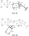
- FIGS. 3A-3E are perspective views of an exemplary tow vehicle along a second predetermined path for determining a length of an attached trailer.
- FIG. 4 is a schematic view of an exemplary graph for determining a length of a trailer attached to a tow vehicle.
- FIG. 5 is a flow diagram of an exemplary arrangement of operations for determining a length of a trailer attached to a tow vehicle.
- FIG. 6 is a flow diagram of an exemplary arrangement of operations for determining the length of a trailer attached to a tow vehicle in a semi-manual mode.
- FIG. 7 is a flow diagram of an exemplary arrangement of operations for determining the length of a trailer attached to a tow vehicle in an autonomous mode.
- FIGS. 8A and 8B are schematic views of an exemplary image including a vehicle representation and two virtual trailers.
- FIGS. 9A-9D is a schematic view of an exemplary graph illustrating the progress of the vehicle representation and the two virtual trailers as the vehicle and trailer move drive in real time.
- a tow vehicle such as, but not limited to a car, a crossover, a truck, a van, a sports-utility-vehicle (SUV), and a recreational vehicle (RV) may be configured to tow a trailer.
- the tow vehicle connects to the trailer by way of a trailer hitch. It is desirable to have a tow vehicle that is capable of detecting a length of the trailer without having the driver manually enter the length of the trailer. In addition, it is desirable that the tow vehicle is capable of determining the trailer length by executing short maneuvers in a parking lot for example, without the need to drive in a forward direction for a long distance. For example, the trailer length may be determined by driving in a rearward direction only, or a combination of rearward and forward motions. As such, the driver can connect to any trailer and the tow vehicle can detect the length of the trailer.
- a vehicle-trailer system 100 includes a tow vehicle 102 hitched to a trailer 104 by way of a hitch 106 .
- the tow vehicle 102 includes a drive system 110 associated with the tow vehicle 102 that maneuvers the tow vehicle 102 and thus the vehicle-trailer system 100 across a road surface based on drive maneuvers or commands having x, y, and z components, for example.
- the drive system 110 includes a front right wheel 112 , 112 a , a front left wheel 112 , 112 b , a rear right wheel 112 , 112 c , and a rear left wheel 112 , 112 d .
- the drive system 110 may include wheels (not shown) associated with the trailer 104 .
- the drive system 110 may include other wheel configurations as well.
- the drive system 110 may include a motor or an engine 114 that converts one form of energy into mechanical energy allowing the vehicle 102 to move.
- the drive system 110 includes other components (not shown) that are in communication with and connected to the wheels 112 and engine 114 and that allow the vehicle 102 to move, thus moving the trailer 104 as well.
- the drive system 110 may also include a brake system 120 that includes brakes (not shown) associated with each wheel 112 , 112 a - d , where each brake is associated with a wheel 112 a - d and is configured to slow down or stop the wheel 112 a - n from rotating.
- the brake system 120 is connected to one or more brakes supported by the trailer 104 .
- the drive system 110 may also include an acceleration system 122 that is configured to adjust a speed of the tow vehicle 102 and thus the vehicle-trailer system 100 , and a steering system 124 that is configured to adjust a direction of the tow vehicle 102 and thus the vehicle-trailer system 100 .
- the vehicle-trailer system 100 may include other systems as well.
- the tow vehicle 102 may move across the road surface by various combinations of movements relative to three mutually perpendicular axes defined by the tow vehicle 102 : a transverse axis X V , a fore-aft axis Y V , and a central vertical axis Z V .
- the transverse axis X V extends between a right side R and a left side of the tow vehicle 102 .
- a forward drive direction along the fore-aft axis Y V is designated as F V , also referred to as a forward motion.
- an aft or rearward drive direction along the fore-aft direction Y V is designated as R V , also referred to as rearward motion.
- the tow vehicle 102 includes a suspension system (not shown), which when adjusted causes the tow vehicle 102 to tilt about the X V axis and or the Y V axis, or move along the central vertical axis Z V .
- the trailer 104 follows along a path of the tow vehicle 102 . Therefore, when the tow vehicle 102 makes a turn as it moves in the forward direction F V , then the trailer 104 follows along. While turning, the tow vehicle 102 and the trailer 104 form a trailer angle ⁇ ( FIG. 2B ).
- the trailer 104 follows the tow vehicle 102 across the road surface by various combinations of movements relative to three mutually perpendicular axes defined by the trailer 104 : a trailer transverse axis X T , a trailer fore-aft axis Y T , and a trailer central vertical axis Z T .
- the trailer transverse axis X T extends between a right side R and a left side of the trailer 104 .
- a forward drive direction along the trailer fore-aft axis Y T is designated as F T , also referred to as a forward motion.
- a trailer aft or rearward drive direction along the fore-aft direction Y T is designated as R T , also referred to as rearward motion. Therefore, movement of the vehicle-trailer system 100 includes movement of the tow vehicle 102 along its transverse axis X V , fore-aft axis Y V , and central vertical axis Z V , and movement of the trailer 104 along its trailer transverse axis X T , trailer fore-aft axis Y T , and trailer central vertical axis Z T . Therefore, when the tow vehicle 102 makes a turn as it moves in the forward direction F V , then the trailer 104 follows along. While turning, the tow vehicle 102 and the trailer 104 form the trailer angle ⁇ ( FIG. 2B ) being an angle between the vehicle fore-aft axis Y V and the trailer fore-aft axis Y T .
- ⁇ FIG. 2B
- the vehicle 102 includes a sensor system 130 to provide sensor data 136 that may be used to determine one or more measurements, such as, a trailer length L T .
- the vehicle 102 may be autonomous or semi-autonomous, therefore, the sensor system 130 provides reliable and robust autonomous driving.
- the sensor system 130 provides sensor data 136 and may include different types of sensors that may be used separately or with one another to create a perception of the tow vehicle's environment or a portion thereof that is used by the vehicle-trailer system 100 to identify object(s) in its environment and/or in some examples autonomously drive and make intelligent decisions based on objects and obstacles detected by the sensor system 130 .
- the sensor system 130 is supported by the rear portion of the tow vehicle 102 and provides sensor data 136 associated with object(s) and the trailer 104 positioned behind the tow vehicle 102 .
- the tow vehicle 102 may support the sensor system 130 ; while in other examples, the sensor system 130 is supported by the vehicle 102 and the trailer 104 .
- the sensor system 130 may include, but not limited to, one or more imaging devices 132 , 132 a - n (such as camera(s)), and sensors 134 , 134 a - n such as, but not limited to, radar, sonar, LIDAR (Light Detection and Ranging, which can entail optical remote sensing that measures properties of scattered light to find range and/or other information of a distant target), LADAR (Laser Detection and Ranging), etc.
- the sensor system 130 provides sensor data 136 that include one or both of sensor images 133 from the one or more cameras 132 , 132 a - n and sensor information 135 from the one or more sensors 134 , 134 a - n . Therefore, the sensor system 130 is especially useful for receiving information of the environment or portion of the environment of the vehicle and for increasing safety in the vehicle-trailer system 100 which may operate under semi-autonomous or autonomous conditions.
- the tow vehicle 102 may include a user interface 140 , such as a display.
- the user interface 140 is configured to display information to the driver.
- the user interface 140 is configured to receive one or more user commands from the driver via one or more input mechanisms or a touch screen display 142 and/or displays one or more notifications to the driver.
- the user interface 140 is a touch screen display 142 ; as such, the driver may point his finger and select a representation 144 of an action to be performed as shown in FIG. 1A .
- the user interface 140 is not a touchscreen and the driver may use an input device, such as, but not limited to, a rotary knob or a mouse to select the representation 144 of an action to be performed.
- the user interface 140 is in communication with a vehicle controller 150 that includes a computing device (or data processing hardware) 152 (e.g., central processing unit having one or more computing processors) in communication with non-transitory memory or hardware memory 154 (e.g., a hard disk, flash memory, random-access memory) capable of storing instructions executable on the computing processor(s)).
- a computing device or data processing hardware
- non-transitory memory or hardware memory 154 e.g., a hard disk, flash memory, random-access memory
- the non-transitory memory 154 stores instructions that when executed on the computing device 152 cause the vehicle controller 150 to provide a signal or command 174 to the drive system 110 , which leads to a change of a feature of the vehicle 102 .
- the vehicle controller 150 is supported by the tow vehicle 102 ; however, the vehicle controller 150 may be separate from the tow vehicle 102 and in communication with the tow vehicle 102 via a network (not shown).
- the vehicle controller 150 is in communication with the sensor system 130 , and receives sensor data 136 from the sensor system 130 .
- the vehicle controller 150 is configured to process sensor data 136 received from the sensor system 130 .
- the vehicle controller 150 executes a trailer parameter identification function 160 configured to determine a length L T of the trailer 104 that is hitched to the tow vehicle 102 .
- the length L T of the trailer 104 is the distance between the hitch point 106 and the rear axle of the trailer 104 .
- the tow vehicle 102 While attached to the trailer 104 , the tow vehicle 102 follows a path having predefined maneuvers that allow the trailer parameter identification function 160 to determine the length L T of the trailer 104 .
- the trailer parameter identification function 160 receives sensor data 136 from the sensors 135 , 134 of the sensor system 130 that are positioned on the rear side of the tow vehicle 102 while the vehicle-trailer system 100 is moving along the path that includes the predefined maneuvers ( FIGS.
- the trailer parameter identification function 160 determines the length L T of the trailer 104 .
- the trailer parameter identification function 160 may function in a manual mode 160 a , a semi-manual mode 160 b , or an autonomous mode 160 c ( FIG. 1C ).
- the tow vehicle 102 may be configured to function in only one of the manual mode 160 a , a semi-manual mode 160 b , or an autonomous mode 160 c . While in other examples, the driver selects which 160 a - 160 c he/she wants the trailer parameter identification function 160 to execute.
- FIG. 1B shows the trailer parameter identification function 160 configured to execute a manual mode 160 a and/or a semi-manual mode 160 b . While FIG. 1C includes the autonomous mode 160 c.
- the driver follows instructions that include the predetermined maneuvers ( FIGS. 2A-2D or 3A-3D ), which leads to the tow vehicle 102 driving along the path.
- the trailer parameter identification function 160 receives the sensor data 136 from the sensors 135 , 134 positioned on the rear side of the tow vehicle 102 and determines the length L T of the trailer 104 based on the received sensor data 136 .
- the trailer parameter identification function 160 receives the sensor data 136 , while the driver is executing a maneuver, for example, while the driver is tuning left. In other examples, the trailer parameter identification function 160 continuously receives the sensor data 136 .
- the instructions to the driver may be displayed on the user interface 140 or may be provided in a driver manual, for example.
- the semi-manual mode 160 b provides the driver with the predefined maneuvers by way of the user interface 140 to follow the path shown in FIGS. 2A-2D or 3A-3D , and after each maneuver, the driver has to confirm that he/she executed the maneuver. While the driver is following the predefined maneuvers, the trailer parameter identification function 160 receives sensor data 136 from the sensors 135 , 134 positioned on the rear side of the tow vehicle 102 , which allows the trailer parameter identification function 160 to determine the length L T of the trailer 104 . During the semi-manual mode 160 b the driver interacts with the user interface 140 by acknowledging that he/she completed a predefined maneuver. Once the driver completes all predefined maneuvers, the trailer parameter identification function 160 determines the length L T of the trailer.
- a driver may initiate the autonomous mode 160 c by making a selection of the autonomous mode representations 144 c displayed on the user interface 140 . Once the selection of the autonomous mode representations 144 c is made, the tow vehicle 102 autonomously drives along the predetermined maneuvers, while attached to the trailer 104 .
- the vehicle controller 150 receives sensor data 136 from the sensors 132 , 134 positioned on the rear side of the tow vehicle 102 for determining the length L T of the trailer 104 and from sensors 132 , 134 positioned around the tow vehicle 102 and or the vehicle-trailer system 100 , such as on the sides of the vehicle 102 and/or trailer 104 , in front of the vehicle 102 , and on the back of the trailer 104 for identifying objects along the predetermined path to avoid the identified objects.
- the trailer parameter identification function 160 relies on the sensor data 136 received from the sensors 132 , 134 positioned behind the tow vehicle 102 to determine the length L T of the trailer 104 , and relies on all other sensors 132 , 134 to provide autonomous driving along the path that includes the predetermined maneuvers.
- the vehicle controller 150 executes the object detection system 162 .
- the object detection system 162 receives sensor data 136 from the sensor system 130 having cameras 132 and/or sensors 134 positioned around the tow vehicle 102 .
- the object detection system 162 processes the received sensor data 136 and identities one or more objects within the environment of the tow vehicle 102 .
- the object detection system 162 may also receive sensor data from the trailer 104 and identify one or more objects within an environment of the trailer 104 .
- the vehicle controller 150 executes a path planning system 164 that plans a path including the predetermined maneuvers that allow the trailer parameter identification function 160 to determine the length L T of the trailer 104 .
- the path planning system 164 may include maneuvering the tow vehicle 102 in a forward direction F V , a rearward direction R V , or a combination thereof. Therefore, the path may include maneuvering the vehicle-trailer system 100 in a forward direction F V , F T , a rearward direction R V , R T , or a combination thereof.
- the path planning system 164 continuously updates the path based on continuously receiving sensor data 136 from the sensor system 130 .
- the object detection system 162 identifies one or more objects along the planned path and sends the path planning system 164 data relating to the position of the one or more objects.
- the path planning system 164 recalculates the planned path to avoid one or more objects.
- the path planning system 164 determines a probability of collision and if the probability of collision exceeds a predetermined threshold, the path planning system 164 adjusts the path and sends it to a driver assistance system 170 .
- the vehicle controller 150 executes the driver assistance system 170 , which in turn includes path following behaviors 172 .
- the path following behaviors 172 receive the planned path and executes one or more behaviors 172 a - 172 ce that send commands 174 to the drive system 110 , causing the vehicle 102 to autonomously drive along the planned path, which causes the vehicle-trailer system 100 to autonomously drive along the planned path.
- the path following behaviors 172 may include one or more behaviors, such as, but not limited to, a braking behavior 172 a , a speed behavior 172 b , and a steering behavior 172 c .
- Each behavior 172 a - c causes the vehicle 102 , and thus the vehicle-trailer system 100 to take an action, such as driving forward or backward, turning at a specific angle, breaking, speeding, slowing down, among others.
- the vehicle controller 150 may maneuver the vehicle-trailer system 100 in any direction across the road surface by controlling the drive system 110 , more specifically by issuing commands 174 to the drive system 110 .
- the braking behavior 172 a may be executed to either stop the vehicle-trailer system 100 or to reduce the speed of the vehicle-trailer system 100 based on the planned path.
- the braking behavior 172 a sends a signal or command 174 to the drive system 110 , e g., the brake system (not shown), to either stop the vehicle-trailer system 100 or reduce the speed of the vehicle-trailer system 100 .
- the brake system 120 of the tow vehicle 102 may be in communication with a brake system (not shown) of the trailer 104 . Therefore, the braking behavior 172 a may cause the brakes of the tow vehicle 102 and the brakes of the trailer 104 to reduce the speed or stop the vehicle-trailer system 100 .
- the speed behavior 172 b may be executed to change the speed of the vehicle-trailer system 100 by either accelerating or decelerating based on the planned path.
- the speed behavior 172 b sends a signal or command 174 to the brake system 120 for decelerating or the acceleration system 122 for accelerating.
- the steering behavior 172 c may be executed to change the direction of the vehicle-trailer system 100 based on the planned path. As such, the steering behavior 172 c sends the acceleration system 122 a signal or command 174 indicative of an angle of steering causing the drive system 110 to change direction.
- the trailer parameter identification function 160 may determine the length L T of the trailer 104 in one of three modes: a manual mode 160 a , a semi-manual mode 160 b , and an autonomous mode 160 c . Regardless of the mode 160 a - 160 c , the trailer parameter identification function 160 follows a planned path that includes predefined maneuvers. Sensors 132 , 134 of the sensor system 130 positioned on the rear side of the tow vehicle 102 capture sensor data 136 and send the sensor data 136 to the trailer parameter identification function 160 allowing the trailer parameter identification function 160 to determine the length L T of the trailer 104 .
- the trailer parameter identification function 160 receives sensor data 136 as the tow vehicle 102 and the trailer 104 are moving along the path that includes the predefined maneuvers.
- the trailer identification function 160 stores the received sensor data in the hardware memory 154 of the vehicle controller 150 , and once the trailer parameter identification function 160 has received the sensor data 136 associated with each of the predefined maneuvers, then the trailer parameter identification function 160 determines the trailer length L T .
- the trailer parameter identification function 160 receives first sensor data 136 associated with a first maneuver, second sensor data 136 associated with a second maneuver, and third sensor data 136 associated with a third maneuver. Additional maneuvers may also be needed.
- the first vehicle maneuver is a straight line maneuver P 1 a shown in FIG. 2A where the vehicle-trailer system 100 drives in a forward direction F V until the trailer angle ⁇ is equal to zero, i.e., the tow vehicle 102 and the trailer 104 are aligned in a straight line, in other words, the fore-aft axis Y V of the tow vehicle 102 is parallel and aligned with the fore-aft axis Y T of the trailer 104 .
- the vehicle controller 150 may optionally confirm the straight line position by pulling forward a short distance to verify that the trailer angle ⁇ equals to zero. This short forward maneuver P 1 a may also be used to distinguish trailer features from the environment.
- the tow vehicle 102 performs a second maneuver that includes turning its wheels 112 (front and/or rear wheels may be used to steer), more specifically its front wheels 112 a , 112 b to the left or the right as shown at position P 2 a .
- the third maneuver includes the tow vehicle 102 moving in the rearward direction R V causing the trailer 104 to also move in the rearward direction R T , as shown at position P 3 a .
- the movement of the tow vehicle 102 and thus the trailer 104 in the rearwards direction R V , R T causes the trailer angle ⁇ to change to a non-zero angle.
- the front wheels 112 a , 112 b of the tow vehicle 102 are turned in an opposite direction as shown in position P 4 a (third maneuver). For example, if the front wheels 112 a , 112 b were turned to the right in FIG. 2B , then the front wheels 112 a , 112 b are turned to the left in FIG. 2C . In addition, if the front wheels 112 a , 112 b were turned to the left in FIG. 2B , then the front wheels 112 a , 112 b are turned to the right in FIG. 2C .
- the tow vehicle 102 continues its movement in the rearwards direction R V until the trailer reaches a reference position at P 5 a shown in FIG. 2D (fourth maneuver).
- the reference position is when the trailer angle ⁇ is equal to zero as shown in FIG. 2D .
- the vehicle 102 may additionally move in a sequence of short forward maneuvers or forward maneuvers followed by short reverse maneuvers to ensure that the vehicle controller 150 collects enough data points for the trailer parameter identification function 160 to determine the length L T of the trailer 104 .
- the distance between each position after a maneuver is less than a predetermined distance, thus keeping the total maneuvers to a total of a short drive. Therefore, although only four maneuvers are described above, additional maneuvers may be possible to collect enough data points to determine the length L T of the trailer 104 .
- FIGS. 3A-3D illustrate a different set of maneuvers that the tow vehicle 102 may follow that allows the trailer parameter identification function 160 to determine the length L T of the trailer 104 .
- the first vehicle maneuver is a straight line maneuver where the vehicle-trailer system 100 drives in a forward F direction until the trailer angle ⁇ is equal to zero as shown at position P 1 b , i.e., the tow vehicle 102 and the trailer 104 are aligned in a straight line, in other words, the fore-aft axis Y V of the tow vehicle 102 is parallel and aligned with the fore-aft axis Y T of the trailer 104 .
- the vehicle controller 150 may optionally confirm the straight line position by pulling forward a short distance to verify that the trailer angle ⁇ equals to zero. This short forward maneuver P 1 a may also be used to distinguish trailer features from the environment.
- the tow vehicle 102 performs a second maneuver by turning its wheels 112 at position P 2 b , more specifically its front wheels 112 a , 112 b to the left or the right and in a third maneuver begins moving in the rearward direction R V causing the trailer 104 to also move in the rearward direction R T as shown at position P 3 b .
- the movement of the tow vehicle 102 and thus the trailer 104 in the rearward directions R V , R T causes the trailer angle ⁇ to change to a non-zero angle.
- the front wheels 112 a , 112 b of the tow vehicle 102 are turned in an opposite direction in a fourth maneuver as shown at position P 4 b in FIG. 3C .
- the front wheels 112 a , 112 b were turned to the right in FIG. 3B , then the front wheels 112 a , 112 b are turned to the left in FIG. 3C .
- the front wheels 112 a , 112 b were turned to the left in FIG. 3B , then the front wheels 112 a , 112 b are turned to the left in FIG. 3C .
- the tow vehicle 102 moves in a forward direction F V in a fifth maneuver as shown in position P 5 b in FIG. 3D .
- the vehicle-trailer system 100 continues to move in the forward direction F V until the trailer reaches a reference position at P 6 b shown in FIG. 3E .
- the reference position is when the trailer angle ⁇ is equal to zero as shown in FIG. 3E .
- the vehicle 102 may additionally move in a sequence maneuvers to ensure that the vehicle controller 150 collects enough data points for the trailer parameter identification function 160 to determine the length L T of the trailer 104 .
- the trailer parameter identification function 160 receives sensor data 136 from the sensor system 130 while the vehicle 102 drives along the path that includes the predefined maneuvers, specifically from sensors 132 , 134 positioned on the back side of the tow vehicle 102 , and based on the received sensor data 136 determines the length L T of the trailer 104 .
- Several methods may be used to determine the length L T of the trailer 104 .
- the trailer parameter identification function 160 has a predetermined plot of different trailer angles ⁇ versus traveled distance for trailers 104 having different length L T , and based on the determined trailer angle 9 , the function 160 can determine the trailer length L T .
- the short maneuvers described with respect to FIGS. 2A-2D and 3A-3E may result in different trailer angles ⁇ for different trailer lengths L T .
- the trailer angle ⁇ is a function of trailer length L T and other vehicle parameters as shown in the following time domain differential equation (or its kinematic equivalent):
- ⁇ tow is the tow Vehicle's Yaw Rate
- L H is the hitch length (i.e., distance between the center of rear axle of the tow vehicle 102 to the hitch point 106 )
- L T is the Trailer Length (i.e., the distance between the hitch point 106 and the rear axle of the trailer 104 )
- v tow is a speed of the tow vehicle 102 ( FIG. 2A ).
- the X-axis of the graph shows the distance in meters that the tow vehicle 102 covers during the maneuver.
- the difference in this generated data may be utilized to identify trailer parameters of interest of other trailers 104 , in some examples, the stored sensor data 136 may be mapped to the actual trailer angle ⁇ . In instances where the sensor data 136 includes sensor images 133 , a three-dimensional position of the tracked points/features may be identified and the trailer angle ⁇ may be available.
- FIG. 5 illustrates a flow chart 500 of a vehicle 102 having a trailer parameter identification function 160 for detecting a trailer length L T , as described in FIGS. 1A-1C .
- the driver indicates via the user interface 140 of the tow vehicle 102 that the driver wants the vehicle 102 , i.e., the vehicle controller 150 to initiates calculation of the trailer length L T .
- the vehicle controller 150 prompts the driver to select one of three modes, a manual mode 160 a , a semi-manual mode 160 b , or an autonomous mode 160 c . For example, referring to FIG.
- the display 142 provides the driver with representations 144 of three options, a manual mode representation 144 a , a semi-manual mode representation 144 b , and an autonomous mode representations 144 c .
- a selection of one of the representations 144 a - 144 c causes the vehicle controller 150 to execute one of the modes 160 a - 160 c .
- the driver has the option of selecting a mode from the three available modes 160 a - 160 c ; however, in some examples, the driver does not have an option to select and the vehicle controller provides the driver with one of the modes 160 a - 160 c.
- the vehicle controller 150 determines which selection the driver made. If the driver selected a manual mode 160 a , then at block 50 the vehicle controller 150 triggers the sensor system 130 to start capturing sensor data 136 and storing it on the memory hardware 154 as the vehicle 102 is moving along the planned path and sends the sensor data 136 to the trailer parameter identification function 160 .
- the driver has a set of instructions, for example, a hard copy of a manual or instructions displayed on the user interface 140 that instructs the driver of the maneuvers ( FIGS. 2A-2C or FIGS. 3A-3D ) that he needs to perform. As such, the driver drives the tow vehicle 102 along the path shown in the FIGS. 2A-2C or FIGS.
- the vehicle controller 150 determines if the vehicle-trailer system 100 has reached the reference position shown in FIG. 2D or 3E . If the vehicle controller 150 determines that the vehicle-trailer system 100 has not reached the reference position, then the sensor system 130 keeps capturing sensor data 136 and sending it to the vehicle controller 150 . Once the vehicle-trailer system 100 has reached the reference position, then the trailer parameter identification function 160 has enough data points within the sensor data 136 to determine the length L T of the trailer 104 . At block 506 , if driver selects semi-manual mode 160 b or if the vehicle controller 150 only provides semi-manual mode 160 b , then the vehicle controller 150 executes the process shown in FIG. 6 . In addition, at block 506 , if the driver selects autonomous mode 160 c or if the vehicle controller 150 only provides autonomous mode 160 c , then the vehicle controller 150 executes the process shown in FIG. 7 .
- FIG. 6 shows a flow chart that the vehicle controller 150 executes during the semi-manual mode 160 b , which provides the driver with a set of instructions that the driver has to follow, and upon completion of each instruction, the driver provides a confirmation input via the user interface 140 to the trailer parameter identification function 160 before moving to the next instruction.
- Each instruction includes a maneuver that the driver has to driver the tow vehicle 102 for a period of time or a specific distance. The maneuvers may include, but not limited to, turn left and drive for 40 feet, drive straight for 20 feet, turn left and drive at a speed of 20 miles per hour for 1 minute.
- the trailer parameter identification function 160 starts executing the semi-manual mode 160 b , and at decision block 604 , the trailer parameter identification function 160 determines if the trailer 104 is in a straight line with respect to the tow vehicle 102 . In other words, the trailer parameter identification function 160 determines if the fore-aft axis Y V of the tow vehicle 102 is substantially aligned or parallel with the fore-aft axis Y T of the tow vehicle 102 .
- the trailer parameter identification function 160 determines that the fore-aft axis Y V of the tow vehicle 102 is not substantially aligned or parallel with the fore-aft axis Y T of the tow vehicle 102 , then the trailer parameter identification function 160 sends a signal to the user interface 140 to prompt the driver to driver the vehicle-trailer system 100 in a forward direction F V , for example, for a specific distance or a specific time.
- the trailer parameter identification function 160 determines that the fore-aft axis Y V of the tow vehicle 102 is substantially aligned or parallel to the fore-aft axis Y T of the tow vehicle 102 . If, at decision block 604 , the trailer parameter identification function 160 determines that the fore-aft axis Y V of the tow vehicle 102 is substantially aligned or parallel to the fore-aft axis Y T of the tow vehicle 102 , then the trailer parameter identification function 160 begins sensing and/or storing sensor data 136 from the sensor system 130 positioned on the rear portion of the tow vehicle 102 . The trailer parameter identification function 160 sends a signal to the user interface 140 to prompt the user to perform a turn maneuver, for example, the trailer parameter identification function 160 sends the user interface 140 a signal to display a message to the driver to turn the wheels 112 of the tow vehicle 102 in a first direction (position P 2 a shown in FIG.
- the trailer parameter identification function 160 waits for the driver to input a confirmation indication via the user interface 140 that the driver did move the wheels 112 in the first direction and drove in the rearward direction R V .
- the trailer parameter identification function 160 sends the user interface 140 a signal to display a message to the driver to turn the wheels 112 of the tow vehicle 102 in a second direction opposite the first direction.
- the message may indicate that the driver can either stop the tow vehicle 102 and turn the wheels 112 or turn the wheels while the vehicle 102 is moving ( FIG. 2C and FIG. 3C ).
- the trailer parameter identification function 160 waits for a confirmation from the driver via the user interface 140 that the driver performed the maneuver.
- the trailer parameter identification function 160 sends the user interface 140 a signal to display a message to the driver to drive the tow vehicle 102 in a rearward direction R ( FIG. 2D ) or a forward direction ( FIG. 3D ).
- the trailer parameter identification function 160 determines if the trailer 104 has reached the reference position (position P 5 a shown in FIG.
- the trailer parameter identification function 160 determines if it has enough data points to calculate or determine the trailer length L T . If the trailer parameter identification function 160 determines that it needs more data points to determine the trailer length L T , then at block 622 , the trailer parameter identification function 160 sends a message to the user interface 140 to prompt the driver to perform a specific maneuver that is needed to get more data points. Once the trailer parameter identification function 160 has enough data points and the trailer 104 has reached a reference position at decision block 620 , then at block 624 , the trailer parameter identification function 160 determines the length L T of the trailer 104 .
- FIG. 7 shows a flow chart 700 that the vehicle controller 150 executes during the autonomous mode 160 c .
- the autonomous mode 160 c allows the driver to instruct the vehicle controller 150 via the user interface 140 , that he/she wants the vehicle controller 150 to autonomously maneuver the vehicle-trailer system 100 along the paths described in FIGS. 2A-2D or FIGS. 3A-3D and determine the length L T of the trailer 104 .
- the vehicle controller 150 receives sensor data 136 from sensors positioned around the vehicle 102 and in some examples in the trailer 104 as well.
- the vehicle controller 150 Upon the driver selection of the autonomous mode 160 c the vehicle controller 150 begins executing the trailer parameter identification function 160 in the autonomous mode 160 c at block 702 . Similar to the semi-manual mode 160 b , at decision block 704 , the trailer parameter identification function 160 determines if the trailer 104 is in a straight line with respect to the tow vehicle 102 . In other words, the trailer parameter identification function 160 determines if the fore-aft axis Y V of the tow vehicle 102 is substantially aligned or parallel with the fore-aft axis Y T of the tow vehicle 102 .
- the trailer parameter identification function 160 determines that the fore-aft axis Y V of the tow vehicle 102 is not substantially aligned or parallel with the fore-aft axis Y T of the tow vehicle 102 , then the trailer parameter identification function 160 sends a signal to the driver assistance system 170 to send a command 174 to the drive system 110 that causes the vehicle-trailer system to be aligned, at block 706 .
- the driver assistance system 170 instructs the drive system 110 to move in the forwards direction until the vehicle-trailer system 100 is aligned, or in other words, the tow vehicle 102 and the trailer 104 are aligned.
- the vehicle controller 150 instructs the drive system 110 to turn the front wheels 112 a , 112 b in a first direction and move in a rearward direction R V also causing the trailer 104 to move in the rearward direction R T .
- the vehicle controller 150 instructs the drive system 110 to turn the vehicle front wheels 112 a , 112 b in a second direction.
- the second direction is a direction opposite from the first direction
- the second direction shown in FIG. 3C is a direction having a greater angle than the first direction.
- the drive system 110 may either turn the vehicle front wheels 112 a , 112 b in the second direction without stopping or stop the tow vehicle 102 then turn the front wheels 112 a , 112 b.
- the vehicle controller 150 instructs the drive system 110 to move in the forward direction ( FIG. 2D ) or the rearwards direction ( FIG. 3E ). Then at decision block 714 , the vehicle controller 150 , for example, the trailer parameter identification function 160 determines if the trailer 104 has reached the reference position (position P 5 a shown in FIG. 2D ; position P 6 b shown in FIG. 3F ). In other words, the trailer parameter identification function 160 determines if it has enough data points to calculate or determine the trailer length L T .
- the vehicle controller 150 instructs the drive system 110 to perform a maneuver that allows the trailer parameter identification function 160 to receive additional sensor data 136 from the sensor system 130 allowing the trailer parameter identification function 160 to determine the length L T of the trailer 104 .
- the trailer parameter identification function 160 determines the length of the trailer 104 .
- FIGS. 8A-9D provide another method for determining the trailer length L T based on a simulation of one or more virtual trailer movements in addition to the movement of the actual trailer representation 804 in real time.
- the controller 150 i.e., the trailer parameter identification function 160 , simulates a sequence of virtual trailers 802 , each associated with a different trailer axle length L VT1 , L VT2 and determines the actual trailer length L T based on the simulation of the movement of the one or more virtual trailers 802 having different trailer axle lengths L VT1 , L VT2 .
- FIGS. 8A and 8B illustrate the virtual trailer 802 overlain on the images 133 received from the rear camera 132 a where each image 133 includes a trailer representation 804 of the actual trailer 104 . While FIGS. 9A-9D show a real time graph 900 a associated with movements of the virtual trailers 802 and the trailer representations 804 .
- the vehicle controller 150 receives images 133 from the rear camera 132 a , For each received image 133 , the vehicle controller 150 identifies the trailer representation 804 within the received image(s) 133 and associates a first actual trailer generalized position q, q t1 with the trailer representations 804 .
- the generalized position q, q t1 may be in any coordinate system. In some examples, the generalized position is the position of the pixels associated with the trailer representation 804 within the image 133 .
- the controller 150 also overlays one or more virtual trailers 802 , 802 a , 802 b on the image 133 . Additional virtual trailers may also be overlaid on the images 133 .
- a first virtual trailer 802 a represents a trailer having the same width and height of the actual trailer 104 , however a shorter axle length L VT1 than the axle length L T of the actual trailer 104 .
- a second virtual trailer 802 b represents a trailer having the same width and height of the actual trailer 104 , however a longer axle length L VT2 than the axle length L T of the actual trailer 104 .
- FIG. 8A shows a first position of the trailer representation 804 being aligned with the vehicle 102 , also referred to as a straight trailer.
- the generalized positions q associated with the actual trailer representation 804 and the virtual trailers 802 a , 802 b are the same, since all the trailers 802 , 804 are aligned with the vehicle 102 .
- the behavior of the generalized trailer position q may be compared with the behavior of the virtual trailers 802 a , 802 b to determine the length L T of the trailer 104 .
- FIG. 8A shows the trailer representation 804 and the virtual trailers 802 a , 802 b at an initial position being aligned with the vehicle 102 .
- FIG. 8B shows the trailer representation 804 and the virtual trailers 802 a , 802 b while the trailer 104 is following the maneuvers described in FIGS. 2A-2D or FIGS. 3A-3E .
- the controller 150 records the time s at which the virtual trailers 802 a , 802 b reach a predefined angle ⁇ p with respect to the fore-aft axis Y T , the position of the trailer representation 804 at the recorded time s, and the time at which the trailer representation 804 reaches the predefined angle ⁇ p a second time.
- the predefined angle ⁇ p may be, but is not limited to, 5 degrees, 10 degree, 20 degrees, or any other angle.
- FIG. 9A shows a graph of trajectories 904 , 902 a , 902 b of the actual trailer 104 and the first and second trailers 804 a , 804 b as they follow the maneuvers.
- An actual trajectory 904 represents a trajectory of the actual trailer 104 .
- a first trajectory 902 a is associated with the first virtual trailer 802 a and a second trajectory 902 b is associated with the second virtual trailer 802 b .
- the horizontal axis represents the time s, while the vertical axis represents the generalized position q.
- the generalized position q is associated with a trailer angle ⁇ . Therefore, each time the trailer 104 moves then the trailer representation 804 moves as well.
- the controller 150 considers that for each trailer angle ⁇ a single position q is also obtained.
- the controller 150 records the time s and the actual trailer position q as shown at (b) in FIGS. 9C and 9D .
- the controller 150 records the time s that the virtual trailer 802 a , 802 b returns to the predefined angle ⁇ p , as shown at (c) in FIGS. 9C and 9D . Finally, the controller 150 records the time s at which the position q of the trailer representation 804 returns to the position recorded at (b). The controller 150 determines a first difference of the time s at (h) and (c) which result in a virtual time difference. In addition, the controller determines a second difference in time s at (b) and (d) which results in a measured time difference.
- a third difference between the virtual time difference and the actual time difference results in a value having one sign for all virtual trailers 802 a shorter than the actual trailer 104 (e.g., a negative sign) and another sign for all virtual trailers 802 b longer than the actual trailer 104 (e.g., a positive sign).
- the controller 150 interpolates between the two values determined by the third difference, which results in an estimated trailer axle length L T associated with the actual trailer 104 .
- Several interpolation techniques may be used.
- the controller 150 records a first time s a1 at which the first virtual trailer 802 a crosses the predefined angle ⁇ p and the position q t2 of the trailer representation 802 within the image 133 , as shown at (b). Then the controller 150 records a second time s a2 at which the first virtual trailer 802 a returns to the predefined angle ⁇ p , as shown at (c). Finally, the controller 150 records the time s V at which the position q of the trailer representation 804 returns to the position recorded at (b), i.e., position q t2 .
- the controller 150 determines the third difference D a3 between the virtual time difference D a1 and the actual time difference D a2 , which results in a value having one sign for all virtual trailers 802 a shorter than the actual trailer 104 (e.g., a negative sign) and another sign for all virtual trailers 802 b longer than the actual trailer 104 (e.g., a positive sign).
- the controller 150 records a first time s b1 at which the second virtual trailer 802 b crosses the predefined angle ⁇ p and the position go of the trailer representation 802 within the image 133 , as shown at (b). Then the controller 150 records a second time s b2 at which the second virtual trailer 802 b returns to the predefined angle ⁇ p as shown at (c). Finally, the controller 150 records the time s V at which the position q of the trailer representation 804 returns to the position recorded at (b), i.e., position q t3 .
- the controller 150 interpolates between the two values determined by the third difference D a3 , D b3 , which results in an estimated trailer axle length L T associated with the actual trailer 104 .
- the controller 150 executes higher order interpolation scheme across more than two virtual trailers 802 .
- the same method may also be applied to multiple predefined angles ⁇ in a single event, i.e., in real time. An estimate may be rejected as erroneous if the values of q and s for the various angles ⁇ are not within a predefined tolerance.
- the controller 150 may execute a coarse length detection scheme by cycling through the data a second time with a finer set of virtual trailer axle length L t values in the close vicinity of the original prediction.
- the controller 150 determines a trailer angle ⁇ of the actual trailer 104 . Therefore, once the controller 150 completes estimating the length L T of the trailer 104 , the controller 150 may generate a mapping of the generalized positions q to the trailer angles ⁇ . The controller 150 may then use the mapping to determine an estimated trailer angle ⁇ based on a generalized position q, or vice versa.
- the controller 150 described above is capable of determining the trailer length L T rapidly and automatically, with simultaneous trailer angle calibration (e.g., mapping the generalized positions q to the actual trailer angles (p, as described above).
- the controller 150 provides a target less solution, which means that the driver does not have to add a marker or sticker on the trailer 104 to identify the trailer 104 for the trailer length detection.
- the described system reduces complexity and cost of the embedded hardware needed to run the trailer length detection algorithms.
- the system limits the manual calibration needed by the driver, which may be prone to errors in measuring the trailer and or inputting the measure trailer length in the system.
- implementations of the systems and techniques described here can be realized in digital electronic circuitry, integrated circuitry, specially designed ASICs (application specific integrated circuits), computer hardware, firmware, software, and/or combinations thereof.
- ASICs application specific integrated circuits
- These various implementations can include implementation in one or more computer programs that are executable and/or interpretable on a programmable system including at least one programmable processor, which may be special or general purpose, coupled to receive data and instructions from, and to transmit data and instructions to, a storage system, at least one input device, and at least one output device.
- Implementations of the subject matter and the functional operations described in this specification can be implemented in digital electronic circuitry, or in computer software, firmware, or hardware, including the structures disclosed in this specification and their structural equivalents, or in combinations of one or more of them.
- subject matter described in this specification can be implemented as one or more computer program products, i.e., one or more modules of computer program instructions encoded on a computer readable medium for execution by, or to control the operation of, data processing apparatus.
- the computer readable medium can be a machine-readable storage device, a machine-readable storage substrate, a memory device, a composition of matter effecting a machine-readable propagated signal, or a combination of one or more of them.
- data processing apparatus encompass all apparatus, devices, and machines for processing data, including by way of example a programmable processor, a computer, or multiple processors or computers.
- the apparatus can include, in addition to hardware, code that creates an execution environment for the computer program in question, e.g., code that constitutes processor firmware, a protocol stack, a database management system, an operating system, or a combination of one or more of them.
- a propagated signal is an artificially generated signal, e.g., a machine-generated electrical, optical, or electromagnetic signal that is generated to encode information tier transmission to suitable receiver apparatus.
Abstract
Description
where, ωtow is the tow Vehicle's Yaw Rate, LH is the hitch length (i.e., distance between the center of rear axle of the
Claims (21)
Priority Applications (6)
| Application Number | Priority Date | Filing Date | Title |
|---|---|---|---|
| US16/135,632 US11215451B2 (en) | 2017-09-20 | 2018-09-19 | Trailer length detection system |
| AU2018336887A AU2018336887B2 (en) | 2017-09-20 | 2018-09-20 | Trailer length detection system |
| EP18788931.6A EP3684633B1 (en) | 2017-09-20 | 2018-09-20 | Trailer length detection system |
| PCT/US2018/051884 WO2019060506A1 (en) | 2017-09-20 | 2018-09-20 | Trailer length detection system |
| JP2020516670A JP6935009B2 (en) | 2017-09-20 | 2018-09-20 | Trailer length detection system |
| CN201880075035.8A CN111344165B (en) | 2017-09-20 | 2018-09-20 | Trailer length detection system |
Applications Claiming Priority (2)
| Application Number | Priority Date | Filing Date | Title |
|---|---|---|---|
| US201762560899P | 2017-09-20 | 2017-09-20 | |
| US16/135,632 US11215451B2 (en) | 2017-09-20 | 2018-09-19 | Trailer length detection system |
Publications (2)
| Publication Number | Publication Date |
|---|---|
| US20190086204A1 US20190086204A1 (en) | 2019-03-21 |
| US11215451B2 true US11215451B2 (en) | 2022-01-04 |
Family
ID=65720005
Family Applications (1)
| Application Number | Title | Priority Date | Filing Date |
|---|---|---|---|
| US16/135,632 Active 2039-08-22 US11215451B2 (en) | 2017-09-20 | 2018-09-19 | Trailer length detection system |
Country Status (6)
| Country | Link |
|---|---|
| US (1) | US11215451B2 (en) |
| EP (1) | EP3684633B1 (en) |
| JP (1) | JP6935009B2 (en) |
| CN (1) | CN111344165B (en) |
| AU (1) | AU2018336887B2 (en) |
| WO (1) | WO2019060506A1 (en) |
Families Citing this family (15)
| Publication number | Priority date | Publication date | Assignee | Title |
|---|---|---|---|---|
| US10086870B2 (en) * | 2015-08-18 | 2018-10-02 | Magna Electronics Inc. | Trailer parking assist system for vehicle |
| US20190129429A1 (en) * | 2017-10-26 | 2019-05-02 | Uber Technologies, Inc. | Systems and Methods for Determining Tractor-Trailer Angles and Distances |
| US10955540B2 (en) | 2017-12-01 | 2021-03-23 | Aptiv Technologies Limited | Detection system |
| US10780893B2 (en) * | 2018-03-29 | 2020-09-22 | Veoneer Us, Inc. | System and method for estimating the length of a trailer attached to a vehicle |
| US10838054B2 (en) * | 2018-10-08 | 2020-11-17 | Aptiv Technologies Limited | Detection system and method |
| US11092668B2 (en) | 2019-02-07 | 2021-08-17 | Aptiv Technologies Limited | Trailer detection system and method |
| US11034298B2 (en) * | 2019-11-18 | 2021-06-15 | Continental Automotive Systems, Inc. | Vehicle surround view system for identifying unobservable regions while reversing a trailer |
| US11408995B2 (en) | 2020-02-24 | 2022-08-09 | Aptiv Technologies Limited | Lateral-bin monitoring for radar target detection |
| WO2022061102A1 (en) * | 2020-09-17 | 2022-03-24 | Rivian Ip Holdings, Llc | Systems and methods for controlling an inverter of a towed electric vehicle |
| FR3116622A1 (en) * | 2020-11-25 | 2022-05-27 | Renault S.A.S. | Method for determining a distance separating a pivot point at the rear of a vehicle from an axle axis of a trailer attached to the pivot point. |
| CN112683216B (en) * | 2020-12-22 | 2022-09-09 | 阿波罗智联(北京)科技有限公司 | Method and device for generating vehicle length information, road side equipment and cloud control platform |
| DE102021203659B3 (en) * | 2021-04-14 | 2022-08-25 | Zf Friedrichshafen Ag | Device for determining the length of a vehicle combination |
| EP4098463A1 (en) * | 2021-06-04 | 2022-12-07 | Volvo Truck Corporation | A method for estimating an effective length of a first vehicle segment of a vehicle combination |
| US20230061195A1 (en) * | 2021-08-27 | 2023-03-02 | Continental Automotive Systems, Inc. | Enhanced transparent trailer |
| JP2024003665A (en) * | 2022-06-27 | 2024-01-15 | トヨタ自動車株式会社 | Device for traction vehicle and control method of device for traction vehicle |
Citations (14)
| Publication number | Priority date | Publication date | Assignee | Title |
|---|---|---|---|---|
| US20060071447A1 (en) * | 2004-06-17 | 2006-04-06 | Ottmar Gehring | Process for coupling a trailer to a motor vehicle |
| WO2014019730A1 (en) | 2012-08-03 | 2014-02-06 | Volkswagen Aktiengesellschaft | Method and device for manoeuvring a trailer |
| US20140160275A1 (en) * | 2012-12-04 | 2014-06-12 | Aisin Seiki Kabushiki Kaisha | Vehicle control apparatus and vehicle control method |
| US20140160276A1 (en) * | 2012-09-26 | 2014-06-12 | Magna Electronics Inc. | Vehicle vision system with trailer angle detection |
| US20140188344A1 (en) * | 2011-04-19 | 2014-07-03 | Ford Global Technologies, Llc | System and method of calibrating a trailer backup assist system |
| US20140267688A1 (en) * | 2011-04-19 | 2014-09-18 | Ford Global Technologies, Llc | Display system utilizing vehicle and trailer dynamics |
| US20140303849A1 (en) * | 2011-04-19 | 2014-10-09 | Ford Global Technologies, Llc | Trailer backup assist system with trajectory planner for multiple waypoints |
| US20140303827A1 (en) * | 2013-04-05 | 2014-10-09 | Google Inc. | Systems and Methods for Transitioning Control of an Autonomous Vehicle to a Driver |
| WO2015001065A1 (en) | 2013-07-04 | 2015-01-08 | Jaguar Land Rover Limited | Trailer parameter identification system |
| DE102014005681A1 (en) | 2014-04-16 | 2015-10-22 | Audi Ag | Method for driver assistance during a journey, in particular a reverse drive, of a motor vehicle with a trailer and associated motor vehicle |
| DE102015210816A1 (en) | 2015-06-12 | 2016-12-15 | Audi Ag | Determining a length of a trailer |
| US20180354553A1 (en) * | 2017-06-13 | 2018-12-13 | Bayerische Motoren Werke Aktiengesellschaft | Control System for Steering a Towing Vehicle with a Trailer |
| US20190308641A1 (en) * | 2016-07-14 | 2019-10-10 | Nippon Seiki Co., Ltd. | Image control apparatus and display apparatus |
| US20200164920A1 (en) * | 2017-05-11 | 2020-05-28 | Aisin Seiki Kabushiki Kaisha | Traction assist apparatus |
Family Cites Families (6)
| Publication number | Priority date | Publication date | Assignee | Title |
|---|---|---|---|---|
| DE102006007805B4 (en) * | 2006-02-17 | 2008-01-03 | Daimlerchrysler Ag | Method for determining the trailer angle between a towing vehicle and an associated trailer |
| GB2447672B (en) * | 2007-03-21 | 2011-12-14 | Ford Global Tech Llc | Vehicle manoeuvring aids |
| US9108598B2 (en) * | 2011-01-13 | 2015-08-18 | Continental Automotive Systems, Inc. | System and method for maneuvering a vehicle-trailer unit in reverse travel |
| US20140236532A1 (en) * | 2013-02-21 | 2014-08-21 | Ford Global Technologies | Trailer length estimation |
| US9403413B2 (en) * | 2014-05-07 | 2016-08-02 | GM Global Technology Operations LLC | Systems and methods to assist in coupling a vehicle to a trailer |
| DE102015218409A1 (en) * | 2015-09-24 | 2017-03-30 | Zf Friedrichshafen Ag | Device for determining the vertical load of a trailer |
-
2018
- 2018-09-19 US US16/135,632 patent/US11215451B2/en active Active
- 2018-09-20 EP EP18788931.6A patent/EP3684633B1/en active Active
- 2018-09-20 CN CN201880075035.8A patent/CN111344165B/en active Active
- 2018-09-20 WO PCT/US2018/051884 patent/WO2019060506A1/en unknown
- 2018-09-20 JP JP2020516670A patent/JP6935009B2/en active Active
- 2018-09-20 AU AU2018336887A patent/AU2018336887B2/en active Active
Patent Citations (15)
| Publication number | Priority date | Publication date | Assignee | Title |
|---|---|---|---|---|
| US20060071447A1 (en) * | 2004-06-17 | 2006-04-06 | Ottmar Gehring | Process for coupling a trailer to a motor vehicle |
| US20140267688A1 (en) * | 2011-04-19 | 2014-09-18 | Ford Global Technologies, Llc | Display system utilizing vehicle and trailer dynamics |
| US20140303849A1 (en) * | 2011-04-19 | 2014-10-09 | Ford Global Technologies, Llc | Trailer backup assist system with trajectory planner for multiple waypoints |
| US20140188344A1 (en) * | 2011-04-19 | 2014-07-03 | Ford Global Technologies, Llc | System and method of calibrating a trailer backup assist system |
| WO2014019730A1 (en) | 2012-08-03 | 2014-02-06 | Volkswagen Aktiengesellschaft | Method and device for manoeuvring a trailer |
| US20140160276A1 (en) * | 2012-09-26 | 2014-06-12 | Magna Electronics Inc. | Vehicle vision system with trailer angle detection |
| US20140160275A1 (en) * | 2012-12-04 | 2014-06-12 | Aisin Seiki Kabushiki Kaisha | Vehicle control apparatus and vehicle control method |
| US20140303827A1 (en) * | 2013-04-05 | 2014-10-09 | Google Inc. | Systems and Methods for Transitioning Control of an Autonomous Vehicle to a Driver |
| WO2015001065A1 (en) | 2013-07-04 | 2015-01-08 | Jaguar Land Rover Limited | Trailer parameter identification system |
| US20160153778A1 (en) * | 2013-07-04 | 2016-06-02 | Jaguar Land Rover Limited | Trailer parameter identification system |
| DE102014005681A1 (en) | 2014-04-16 | 2015-10-22 | Audi Ag | Method for driver assistance during a journey, in particular a reverse drive, of a motor vehicle with a trailer and associated motor vehicle |
| DE102015210816A1 (en) | 2015-06-12 | 2016-12-15 | Audi Ag | Determining a length of a trailer |
| US20190308641A1 (en) * | 2016-07-14 | 2019-10-10 | Nippon Seiki Co., Ltd. | Image control apparatus and display apparatus |
| US20200164920A1 (en) * | 2017-05-11 | 2020-05-28 | Aisin Seiki Kabushiki Kaisha | Traction assist apparatus |
| US20180354553A1 (en) * | 2017-06-13 | 2018-12-13 | Bayerische Motoren Werke Aktiengesellschaft | Control System for Steering a Towing Vehicle with a Trailer |
Non-Patent Citations (4)
| Title |
|---|
| International Search Report and Written Opinion of the International Searching Authority dated Jan. 30, 2019 for the corresponding PCT application No. PCT/US2018/051884. |
| IP Australia Notice of acceptance for patent application dated Mar. 26, 2021 for the counterpart Australian Patent Application No. 2018336887. |
| IP Australia Office Action dated Dec. 2, 2020 for the counterpart Australian Patent Application No. 2018336887. |
| Japanese Notice of Reasons for Refusal dated Mar. 17, 2021 for the counterpart Japanese Patent Application No. 2020-516670. |
Also Published As
| Publication number | Publication date |
|---|---|
| EP3684633B1 (en) | 2021-11-10 |
| CN111344165B (en) | 2023-10-27 |
| WO2019060506A1 (en) | 2019-03-28 |
| EP3684633A1 (en) | 2020-07-29 |
| CN111344165A (en) | 2020-06-26 |
| AU2018336887A1 (en) | 2020-04-16 |
| JP6935009B2 (en) | 2021-09-15 |
| JP2020534208A (en) | 2020-11-26 |
| AU2018336887B2 (en) | 2021-04-08 |
| US20190086204A1 (en) | 2019-03-21 |
Similar Documents
| Publication | Publication Date | Title |
|---|---|---|
| US11215451B2 (en) | Trailer length detection system | |
| EP3787909B1 (en) | Coupler and tow-bar detection for automated trailer hitching via cloud points | |
| US11148667B2 (en) | Automated reversing by choice of target location | |
| US11198341B2 (en) | Trailer detection and autonomous hitching | |
| EP3790745B1 (en) | Visual object tracker | |
| US11603100B2 (en) | Automated reversing by following user-selected trajectories and estimating vehicle motion | |
| US11669104B2 (en) | User-adjustable trajectories for automated vehicle reversing | |
| US20220161853A1 (en) | Autonomous Truck-Trailer Maneuvering and Parking | |
| US10829045B2 (en) | System and method for calibrating a motion estimation algorithm using a vehicle camera | |
| US20220343535A1 (en) | System and method for estimating relative trailer angle | |
| WO2022246477A1 (en) | A trailer hitch assist system and method | |
| WO2022087561A1 (en) | Trained trailer parking system and method |
Legal Events
| Date | Code | Title | Description |
|---|---|---|---|
| FEPP | Fee payment procedure |
Free format text: ENTITY STATUS SET TO UNDISCOUNTED (ORIGINAL EVENT CODE: BIG.); ENTITY STATUS OF PATENT OWNER: LARGE ENTITY |
|
| STPP | Information on status: patent application and granting procedure in general |
Free format text: DOCKETED NEW CASE - READY FOR EXAMINATION |
|
| STPP | Information on status: patent application and granting procedure in general |
Free format text: NON FINAL ACTION MAILED |
|
| STPP | Information on status: patent application and granting procedure in general |
Free format text: RESPONSE TO NON-FINAL OFFICE ACTION ENTERED AND FORWARDED TO EXAMINER |
|
| STPP | Information on status: patent application and granting procedure in general |
Free format text: FINAL REJECTION MAILED |
|
| STPP | Information on status: patent application and granting procedure in general |
Free format text: RESPONSE AFTER FINAL ACTION FORWARDED TO EXAMINER |
|
| STPP | Information on status: patent application and granting procedure in general |
Free format text: AWAITING TC RESP., ISSUE FEE NOT PAID |
|
| STPP | Information on status: patent application and granting procedure in general |
Free format text: NOTICE OF ALLOWANCE MAILED -- APPLICATION RECEIVED IN OFFICE OF PUBLICATIONS |
|
| AS | Assignment |
Owner name: CONTINENTAL AUTOMOTIVE SYSTEMS, INC., MICHIGAN Free format text: ASSIGNMENT OF ASSIGNORS INTEREST;ASSIGNORS:CRITCHLEY, JAMES H;AHAMED, NIZAR;ALKEILANI, ABDULWAHAB;SIGNING DATES FROM 20210601 TO 20210726;REEL/FRAME:057467/0795 |
|
| STPP | Information on status: patent application and granting procedure in general |
Free format text: AWAITING TC RESP, ISSUE FEE PAYMENT VERIFIED |
|
| STPP | Information on status: patent application and granting procedure in general |
Free format text: PUBLICATIONS -- ISSUE FEE PAYMENT VERIFIED |
|
| STCF | Information on status: patent grant |
Free format text: PATENTED CASE |
|
| AS | Assignment |
Owner name: CONTINENTAL AUTONOMOUS MOBILITY US, LLC., MICHIGAN Free format text: ASSIGNMENT OF ASSIGNORS INTEREST;ASSIGNOR:CONTINENTAL AUTOMOTIVE SYSTEMS, INC.;REEL/FRAME:061100/0178 Effective date: 20220707 |