WO2018012410A1 - 送風装置、車両用空気調和装置 - Google Patents
送風装置、車両用空気調和装置 Download PDFInfo
- Publication number
- WO2018012410A1 WO2018012410A1 PCT/JP2017/024877 JP2017024877W WO2018012410A1 WO 2018012410 A1 WO2018012410 A1 WO 2018012410A1 JP 2017024877 W JP2017024877 W JP 2017024877W WO 2018012410 A1 WO2018012410 A1 WO 2018012410A1
- Authority
- WO
- WIPO (PCT)
- Prior art keywords
- air
- motor
- chamber
- flow passage
- opening
- Prior art date
- Legal status (The legal status is an assumption and is not a legal conclusion. Google has not performed a legal analysis and makes no representation as to the accuracy of the status listed.)
- Ceased
Links
Images


Classifications
-
- F—MECHANICAL ENGINEERING; LIGHTING; HEATING; WEAPONS; BLASTING
- F04—POSITIVE - DISPLACEMENT MACHINES FOR LIQUIDS; PUMPS FOR LIQUIDS OR ELASTIC FLUIDS
- F04D—NON-POSITIVE-DISPLACEMENT PUMPS
- F04D29/00—Details, component parts, or accessories
- F04D29/58—Cooling; Heating; Diminishing heat transfer
- F04D29/5806—Cooling the drive system
-
- B—PERFORMING OPERATIONS; TRANSPORTING
- B60—VEHICLES IN GENERAL
- B60H—ARRANGEMENTS OF HEATING, COOLING, VENTILATING OR OTHER AIR-TREATING DEVICES SPECIALLY ADAPTED FOR PASSENGER OR GOODS SPACES OF VEHICLES
- B60H1/00—Heating, cooling or ventilating [HVAC] devices
- B60H1/00457—Ventilation unit, e.g. combined with a radiator
- B60H1/00471—The ventilator being of the radial type, i.e. with radial expulsion of the air
-
- B—PERFORMING OPERATIONS; TRANSPORTING
- B60—VEHICLES IN GENERAL
- B60H—ARRANGEMENTS OF HEATING, COOLING, VENTILATING OR OTHER AIR-TREATING DEVICES SPECIALLY ADAPTED FOR PASSENGER OR GOODS SPACES OF VEHICLES
- B60H1/00—Heating, cooling or ventilating [HVAC] devices
- B60H1/32—Cooling devices
-
- F—MECHANICAL ENGINEERING; LIGHTING; HEATING; WEAPONS; BLASTING
- F04—POSITIVE - DISPLACEMENT MACHINES FOR LIQUIDS; PUMPS FOR LIQUIDS OR ELASTIC FLUIDS
- F04D—NON-POSITIVE-DISPLACEMENT PUMPS
- F04D25/00—Pumping installations or systems
- F04D25/02—Units comprising pumps and their driving means
- F04D25/06—Units comprising pumps and their driving means the pump being electrically driven
-
- F—MECHANICAL ENGINEERING; LIGHTING; HEATING; WEAPONS; BLASTING
- F04—POSITIVE - DISPLACEMENT MACHINES FOR LIQUIDS; PUMPS FOR LIQUIDS OR ELASTIC FLUIDS
- F04D—NON-POSITIVE-DISPLACEMENT PUMPS
- F04D25/00—Pumping installations or systems
- F04D25/02—Units comprising pumps and their driving means
- F04D25/08—Units comprising pumps and their driving means the working fluid being air, e.g. for ventilation
- F04D25/082—Units comprising pumps and their driving means the working fluid being air, e.g. for ventilation the unit having provision for cooling the motor
-
- F—MECHANICAL ENGINEERING; LIGHTING; HEATING; WEAPONS; BLASTING
- F04—POSITIVE - DISPLACEMENT MACHINES FOR LIQUIDS; PUMPS FOR LIQUIDS OR ELASTIC FLUIDS
- F04D—NON-POSITIVE-DISPLACEMENT PUMPS
- F04D29/00—Details, component parts, or accessories
- F04D29/40—Casings; Connections of working fluid
- F04D29/42—Casings; Connections of working fluid for radial or helico-centrifugal pumps
- F04D29/4206—Casings; Connections of working fluid for radial or helico-centrifugal pumps especially adapted for elastic fluid pumps
- F04D29/4226—Fan casings
-
- F—MECHANICAL ENGINEERING; LIGHTING; HEATING; WEAPONS; BLASTING
- F04—POSITIVE - DISPLACEMENT MACHINES FOR LIQUIDS; PUMPS FOR LIQUIDS OR ELASTIC FLUIDS
- F04D—NON-POSITIVE-DISPLACEMENT PUMPS
- F04D29/00—Details, component parts, or accessories
- F04D29/58—Cooling; Heating; Diminishing heat transfer
- F04D29/582—Cooling; Heating; Diminishing heat transfer specially adapted for elastic fluid pumps
-
- B—PERFORMING OPERATIONS; TRANSPORTING
- B60—VEHICLES IN GENERAL
- B60H—ARRANGEMENTS OF HEATING, COOLING, VENTILATING OR OTHER AIR-TREATING DEVICES SPECIALLY ADAPTED FOR PASSENGER OR GOODS SPACES OF VEHICLES
- B60H1/00—Heating, cooling or ventilating [HVAC] devices
-
- B—PERFORMING OPERATIONS; TRANSPORTING
- B60—VEHICLES IN GENERAL
- B60H—ARRANGEMENTS OF HEATING, COOLING, VENTILATING OR OTHER AIR-TREATING DEVICES SPECIALLY ADAPTED FOR PASSENGER OR GOODS SPACES OF VEHICLES
- B60H1/00—Heating, cooling or ventilating [HVAC] devices
- B60H1/00007—Combined heating, ventilating, or cooling devices
- B60H1/00021—Air flow details of HVAC devices
- B60H1/00035—Air flow details of HVAC devices for sending an air stream of uniform temperature into the passenger compartment
-
- F—MECHANICAL ENGINEERING; LIGHTING; HEATING; WEAPONS; BLASTING
- F04—POSITIVE - DISPLACEMENT MACHINES FOR LIQUIDS; PUMPS FOR LIQUIDS OR ELASTIC FLUIDS
- F04D—NON-POSITIVE-DISPLACEMENT PUMPS
- F04D25/00—Pumping installations or systems
- F04D25/02—Units comprising pumps and their driving means
- F04D25/08—Units comprising pumps and their driving means the working fluid being air, e.g. for ventilation
-
- F—MECHANICAL ENGINEERING; LIGHTING; HEATING; WEAPONS; BLASTING
- F04—POSITIVE - DISPLACEMENT MACHINES FOR LIQUIDS; PUMPS FOR LIQUIDS OR ELASTIC FLUIDS
- F04D—NON-POSITIVE-DISPLACEMENT PUMPS
- F04D29/00—Details, component parts, or accessories
- F04D29/58—Cooling; Heating; Diminishing heat transfer
- F04D29/582—Cooling; Heating; Diminishing heat transfer specially adapted for elastic fluid pumps
- F04D29/5826—Cooling at least part of the working fluid in a heat exchanger
Definitions
- the present invention relates to a blower and an air conditioner for a vehicle.
- Patent Document 1 discloses a configuration in which water droplets are prevented from entering the chamber by forming a step in an air intake port for taking in air from the discharge nozzle into the chamber.
- This invention is made in view of such a situation, Comprising: It aims at providing the air blower and the air harmony device for vehicles which can prevent arrival of a water droplet to a motor more certainly. .
- a blower according to the present invention comprises a casing provided with an air intake, an air discharge, and a flow passage portion communicating the air intake and the air discharge, and the casing provided in the casing
- the motor cooling unit has a chamber for taking in part of the air from the flow passage, and an opening opened in the chamber, and the air in the chamber taken in from the opening is fed to the motor
- a ceiling portion of the chamber includes an inclined surface which is inclined downward from above.
- the air taken into the casing from the air intake by the fan rotationally driven by the motor is sent out to the flow path portion.
- a portion of the air flowing through the flow passage is taken into the chamber and supplied from the opening through the duct to the motor to cool the motor.
- the inclined surface be formed at least vertically above the opening.
- the inclined surface is formed in an umbrella shape which is gradually inclined downward from the central portion of the ceiling toward the radially outer side.
- a water droplet when a water droplet adheres to a ceiling part, a water droplet can be guide
- An air conditioner for a vehicle according to the present invention includes any one of the above-described blowers.
- the air conditioning apparatus for vehicles which concerns on this invention, it can suppress that a water droplet entraps into a motor cooling part, and it can prevent reaching a motor by providing an inclined surface in a ceiling part in a blower.
- the arrival of water droplets to the motor can be more reliably prevented.
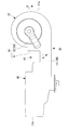
- FIG. 3 is a view showing a configuration of a fan unit of the blower, and is a cross-sectional view taken along the line AA of FIG. It is a longitudinal cross-sectional view of the chamber of the said air blower. It is a longitudinal cross-sectional view of the chamber in the modification of the air blower which concerns on this embodiment.
- FIG. 1 is a plan view showing the internal structure of the air blower according to the present embodiment.
- FIG. 2 is a bottom view of the blower.
- FIG. 3 is a view showing a configuration of a fan portion of the blower, and is a cross-sectional view taken along the line AA of FIG.
- FIG. 4 is a plan sectional view showing the chamber of the blower.
- FIG. 5 is a longitudinal sectional view of the chamber.
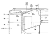
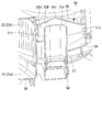
- the air blower 10 which comprises the air conditioning apparatus for vehicles is provided in the hollow casing 11 and the end 11a side of the casing 11, and the fan part 20 which produces a wind, and a fan part A discharge nozzle portion 30 for discharging the air generated at 20, a heat exchanger accommodating portion 40 provided on the other end 11b side of the casing 11 and accommodating the evaporator 41, and a motor cooling portion 50 are provided.
- the casing 11 has an upper and lower split structure, and the upper and lower bottom casings 11A and 11B are combined with each other in the vertical direction. It is formed by connecting.
- the fan unit 20 is formed in the motor 21 (see FIG. 3), the scroll fan 22 provided in the casing 11 and rotationally driven by the motor 21, and the upper casing 11A.
- An air inlet 23 (see FIG. 3) and a scroll passage portion 24 formed radially outward of the scroll fan 22 in the casing 11 are provided.
- the motor 21 has a motor body 21a fitted and held in a motor holding opening 13 formed in the bottom plate portion 11c of the lower casing 11B, and a motor shaft rotationally driven about its axis by the motor body 21a. And 21b.
- the motor 21 is provided in a state in which the motor shaft 21b is protruded upward from the bottom plate portion 11c of the lower casing 11B.
- the scroll fan 22 is provided integrally with the motor shaft 21b above the bottom plate portion 11c of the lower casing 11B.
- the scroll fan 22 has a cylindrical shape provided around the motor shaft 21b, and includes a plurality of blades 22a provided on the outer peripheral portion thereof at intervals in the circumferential direction.
- the scroll fan 22 is rotationally driven integrally with the motor shaft 21 b by the motor 21, and takes in external air from the air intake 23 formed in the upper casing 11 A radially inward of the scroll fan 22. Send radially outward.
- the scroll flow passage portion 24 is continuously formed in the circumferential direction on the radially outer side of the scroll fan 22.
- the scroll flow passage portion 24 is formed such that the flow passage cross-sectional area thereof gradually increases as it goes to the downstream side in the air flow direction along the circumferential direction.
- the discharge nozzle portion 30 has a discharge flow passage portion 31 which is formed in the casing 11 and linearly extends in a tangential direction from the downstream end of the scroll flow passage portion 24 of the fan portion 20. The air fed from the scroll flow passage portion 24 is guided to the downstream side.
- the heat exchanger accommodating portion 40 includes an evaporator 41 accommodated in the casing 11.
- the evaporator 41 is disposed such that the one surface side 41 a thereof is directed to the downstream end 31 b side of the discharge flow passage portion 31 of the discharge nozzle portion 30.
- an air discharge port 14 communicating the inside and the outside of the casing 11 is formed in a portion facing the other surface side 41 b of the evaporator 41.
- the air sent out from the scroll flow path portion 24 and sent in through the discharge flow path portion 31 passes from the one surface side 41 a of the evaporator 41 to the other surface side 41 b.
- Exchange heat with the refrigerant flowing through the The air after heat exchange via the evaporator 41 is discharged from the air discharge port 14 of the casing 11 to the outside of the casing 11.
- the motor cooling unit 50 cools the motor main body 21 a of the motor 21 that rotationally drives the scroll fan 22 of the fan unit 20.
- the motor cooling unit 50 includes a chamber 51 for taking in air from the discharge flow passage 31 of the discharge nozzle unit 30, and a cooling duct 52 for feeding air from the inside of the chamber 51 toward the motor main body 21a.
- the chamber 51 is a portion sandwiched between the discharge flow passage 31 and the scroll flow passage 24. Is formed. Specifically, in the casing 11, the chamber 51 has an outer peripheral wall 11 s located radially outward of the scroll flow passage 24, a side wall 11 t located on one side in the width direction of the discharge flow passage 31, and an outer peripheral wall A flat L-shaped L-shaped wall 53 extending outward from the outer surface of 11s and connected to the outer surface of the side wall 11t, a bottom plate 54 formed on the lower casing 11B, and a ceiling formed on the upper casing 11A It is formed by being surrounded by 55A.
- the chamber 51 is in communication with the discharge flow passage 31 through a communication opening 56 formed in the side wall 11 t, and a part of the air flowing through the discharge flow passage 31 flows into the chamber 51 from the communication opening 56.
- the cooling duct 52 protrudes upward from the bottom plate portion 54 of the chamber 51, and has a cylindrical suction nozzle 57 having an opening 57 a opening vertically upward in the chamber 51, and the suction nozzle 57. And a cylindrical guide passage portion 58 provided along the lower side of the bottom plate portion 11c of the lower casing 11B.
- the guide passage portion 58 includes a spray nozzle 58a for blowing air to the motor main body 21a which protrudes downward from the bottom plate portion 11c of the lower casing 11B.
- the air flowing into the chamber 51 from the discharge flow passage 31 through the communication opening 56 is fed to the suction nozzle 57 from the opening 57 a opened in the chamber 51.
- the air fed into the suction nozzle 57 passes through the guide flow passage portion 58, and is blown to the motor body 21a by the spray nozzle 58a to cool the motor body 21a.
- the ceiling 55A of the chamber 51 is an inclined surface inclined obliquely downward from one end 55a to the other end 55b. It is formed to have 59.
- the inclined surface 59 is formed at least in a region including the vertically upper portion of the opening 57a of the suction nozzle 57 in the ceiling 55A.
- the position of the end 55a in the upper side in the inclination direction and the position of the end 55b in the lower side in the inclination direction are not limited at all.
- the communication opening 56 side may be an end 55b which is lower in the inclination direction, and a side farther from the communication opening 56 may be an end 55a which is upper in the inclination direction.
- the water droplets adhere to the ceiling portion 55A of the chamber 51 due to moisture or the like contained in the air taken into the chamber 51 by the inclined surfaces 59, the water droplets are drawn along the inclined surfaces 59 from above along the inclined direction. It flows down and down. In this embodiment, the water droplets flowing downward along the inclined surface 59 are discharged from the communication opening 56 to the discharge flow passage portion 31.
- the blower 10 has the chamber 51 for taking in part of the air from the discharge flow passage portion 31 and the opening 57a opened in the chamber 51, and the chamber taken in from the opening 57a. And a cooling duct 52 for feeding the air in the motor 51 to the motor 21.
- the ceiling 55A of the chamber 51 has an inclined surface 59 which is inclined downward from above.
- the inclined surface 59 at least vertically above the opening 57a, it is possible to more reliably prevent water droplets from falling into the opening 57a.
- the vehicle air conditioning apparatus (not shown) equipped with the air blower 10 according to the present embodiment, by providing the inclined surface 59 on the ceiling 55A of the air blower 10, the water droplets can be removed from the motor cooling portion 50. Entry into the cooling duct 52 from the opening 57 a can be suppressed, and reaching the motor 21 can be prevented.
- FIG. 5 is a longitudinal cross-sectional view of a chamber in a modification of the air blower according to the present embodiment.
- the ceiling portion 55B of the chamber 51 has an umbrella shape extending obliquely downward from the central portion 55c of the ceiling portion 55B in a plan view toward the outer peripheral end 55d radially outward. It may be formed by the inclined surface 60 of
- the ceiling portion 55B of the chamber 51 has the beveled inclined surface 60, when water droplets adhere to the ceiling portion 55B, the water droplets are directed outward in the radial direction of the ceiling portion 55B. It can lead. Thus, the water droplets can be prevented from entering the cooling duct 52 from the opening 57 a of the motor cooling unit 50 and can be prevented from reaching the motor 21.
Landscapes
- Engineering & Computer Science (AREA)
- Mechanical Engineering (AREA)
- General Engineering & Computer Science (AREA)
- Physics & Mathematics (AREA)
- Thermal Sciences (AREA)
- Structures Of Non-Positive Displacement Pumps (AREA)
- Air-Conditioning For Vehicles (AREA)
Priority Applications (4)
| Application Number | Priority Date | Filing Date | Title |
|---|---|---|---|
| CN201780028614.2A CN109562670B (zh) | 2016-07-15 | 2017-07-06 | 送风装置、车辆用空气调节装置 |
| US16/092,641 US20190170159A1 (en) | 2016-07-15 | 2017-07-06 | Blower device and vehicular air-conditioning device |
| DE112017003590.2T DE112017003590T5 (de) | 2016-07-15 | 2017-07-06 | Gebläsevorrichtung und fahrzeugklimaanlage |
| US17/176,458 US11629724B2 (en) | 2016-07-15 | 2021-02-16 | Blower device and vehicular air-conditioning device |
Applications Claiming Priority (2)
| Application Number | Priority Date | Filing Date | Title |
|---|---|---|---|
| JP2016140550A JP6873622B2 (ja) | 2016-07-15 | 2016-07-15 | 送風装置、車両用空気調和装置 |
| JP2016-140550 | 2016-07-15 |
Related Child Applications (2)
| Application Number | Title | Priority Date | Filing Date |
|---|---|---|---|
| US16/092,641 A-371-Of-International US20190170159A1 (en) | 2016-07-15 | 2017-07-06 | Blower device and vehicular air-conditioning device |
| US17/176,458 Division US11629724B2 (en) | 2016-07-15 | 2021-02-16 | Blower device and vehicular air-conditioning device |
Publications (1)
| Publication Number | Publication Date |
|---|---|
| WO2018012410A1 true WO2018012410A1 (ja) | 2018-01-18 |
Family
ID=60952881
Family Applications (1)
| Application Number | Title | Priority Date | Filing Date |
|---|---|---|---|
| PCT/JP2017/024877 Ceased WO2018012410A1 (ja) | 2016-07-15 | 2017-07-06 | 送風装置、車両用空気調和装置 |
Country Status (5)
| Country | Link |
|---|---|
| US (2) | US20190170159A1 (enExample) |
| JP (1) | JP6873622B2 (enExample) |
| CN (1) | CN109562670B (enExample) |
| DE (1) | DE112017003590T5 (enExample) |
| WO (1) | WO2018012410A1 (enExample) |
Families Citing this family (2)
| Publication number | Priority date | Publication date | Assignee | Title |
|---|---|---|---|---|
| WO2021070356A1 (ja) * | 2019-10-11 | 2021-04-15 | 三菱重工サーマルシステムズ株式会社 | 車両用空調装置 |
| KR102292952B1 (ko) * | 2019-11-21 | 2021-08-23 | 덴소코리아 주식회사 | 차량의 이층류 공조기용 송풍장치 |
Citations (4)
| Publication number | Priority date | Publication date | Assignee | Title |
|---|---|---|---|---|
| JPS6121817A (ja) * | 1984-07-09 | 1986-01-30 | Hitachi Ltd | 自動車用ブロワ装置 |
| JP2007001541A (ja) * | 2005-06-27 | 2007-01-11 | Denso Corp | 送風装置およびこれを備えた車両用空調装置 |
| JP2009525434A (ja) * | 2006-02-01 | 2009-07-09 | ロベルト・ボッシュ・ゲゼルシャフト・ミト・ベシュレンクテル・ハフツング | 遠心ブロワー |
| JP2011252478A (ja) * | 2010-06-04 | 2011-12-15 | Mitsubishi Heavy Ind Ltd | 多翼遠心ファンおよびそれを用いた車両用空調装置 |
Family Cites Families (24)
| Publication number | Priority date | Publication date | Assignee | Title |
|---|---|---|---|---|
| JP3426151B2 (ja) * | 1998-03-16 | 2003-07-14 | アスモ株式会社 | ブラシレスモータ |
| JP2000043532A (ja) * | 1998-07-29 | 2000-02-15 | Denso Corp | 空調装置 |
| JP4273576B2 (ja) | 1999-06-04 | 2009-06-03 | 株式会社デンソー | 車両用空調装置 |
| JP2001180248A (ja) | 1999-12-24 | 2001-07-03 | Denso Corp | 車両用空調装置 |
| JP4185654B2 (ja) * | 2000-08-04 | 2008-11-26 | カルソニックカンセイ株式会社 | 遠心式の多翼送風機 |
| JP4016690B2 (ja) | 2001-07-04 | 2007-12-05 | 株式会社デンソー | 車両用空調装置 |
| KR100651684B1 (ko) * | 2002-05-10 | 2006-11-30 | 한라공조주식회사 | 송풍기 모우터의 냉각장치 |
| FR2856852B1 (fr) * | 2003-06-27 | 2006-09-29 | Asmo Co Ltd | Ensemble moteur pour climatiseur pour vehicules |
| JP2005168268A (ja) * | 2003-12-05 | 2005-06-23 | Asmo Co Ltd | モータの駆動回路装置、及びモータ |
| US7118355B2 (en) * | 2005-02-04 | 2006-10-10 | Delphi Technologies, Inc. | Electric motor driven blower assembly with integral motor cooling duct |
| JP4876841B2 (ja) * | 2005-12-28 | 2012-02-15 | 株式会社デンソー | 送風装置 |
| FR2899654B1 (fr) * | 2006-04-10 | 2008-07-04 | Valeo Systemes Thermiques | Canal de refroidissement pour un moteur de ventilateur d'un systeme de ventilation, chauffage et/ou de climatisation |
| JP4830899B2 (ja) | 2007-02-20 | 2011-12-07 | 株式会社デンソー | 送風機 |
| JP5157762B2 (ja) | 2008-09-02 | 2013-03-06 | 株式会社デンソー | 送風装置 |
| US8267674B2 (en) * | 2010-02-04 | 2012-09-18 | Robert Bosch Gmbh | Centrifugal blower assembly |
| EP2570278B1 (en) * | 2010-03-15 | 2015-12-16 | Valeo Japan Co., Ltd. | Vehicle air conditioning unit |
| JP6088753B2 (ja) * | 2012-06-13 | 2017-03-01 | サンデンホールディングス株式会社 | 車両用空気調和装置 |
| EP2957443B1 (en) * | 2013-02-12 | 2018-05-09 | Mitsubishi Electric Corporation | Outdoor cooling unit for air conditioning device for vehicle |
| JP6098504B2 (ja) | 2013-12-26 | 2017-03-22 | 株式会社デンソー | 車両用空調装置 |
| JP6354309B2 (ja) * | 2014-05-12 | 2018-07-11 | 株式会社デンソー | ブロワ装置 |
| US9647894B2 (en) | 2014-07-30 | 2017-05-09 | International Business Machines Corporation | Mapping relationships among virtual elements across a system |
| CN204786776U (zh) * | 2015-06-08 | 2015-11-18 | 广东美的制冷设备有限公司 | 空调器室内机及具有其的空调器 |
| DE102015113785B4 (de) * | 2015-08-20 | 2018-11-29 | Halla Visteon Climate Control Corporation | Kühlluftschnittstelle in einem Gebläsegehäuse |
| JP6260838B2 (ja) * | 2016-02-29 | 2018-01-17 | 株式会社ケーヒン | 空調用ブロアモータユニット |
-
2016
- 2016-07-15 JP JP2016140550A patent/JP6873622B2/ja active Active
-
2017
- 2017-07-06 DE DE112017003590.2T patent/DE112017003590T5/de active Pending
- 2017-07-06 US US16/092,641 patent/US20190170159A1/en not_active Abandoned
- 2017-07-06 WO PCT/JP2017/024877 patent/WO2018012410A1/ja not_active Ceased
- 2017-07-06 CN CN201780028614.2A patent/CN109562670B/zh active Active
-
2021
- 2021-02-16 US US17/176,458 patent/US11629724B2/en active Active
Patent Citations (4)
| Publication number | Priority date | Publication date | Assignee | Title |
|---|---|---|---|---|
| JPS6121817A (ja) * | 1984-07-09 | 1986-01-30 | Hitachi Ltd | 自動車用ブロワ装置 |
| JP2007001541A (ja) * | 2005-06-27 | 2007-01-11 | Denso Corp | 送風装置およびこれを備えた車両用空調装置 |
| JP2009525434A (ja) * | 2006-02-01 | 2009-07-09 | ロベルト・ボッシュ・ゲゼルシャフト・ミト・ベシュレンクテル・ハフツング | 遠心ブロワー |
| JP2011252478A (ja) * | 2010-06-04 | 2011-12-15 | Mitsubishi Heavy Ind Ltd | 多翼遠心ファンおよびそれを用いた車両用空調装置 |
Also Published As
| Publication number | Publication date |
|---|---|
| JP2018008659A (ja) | 2018-01-18 |
| US20210164480A1 (en) | 2021-06-03 |
| DE112017003590T5 (de) | 2019-05-23 |
| CN109562670A (zh) | 2019-04-02 |
| JP6873622B2 (ja) | 2021-05-19 |
| US20190170159A1 (en) | 2019-06-06 |
| CN109562670B (zh) | 2022-05-03 |
| US11629724B2 (en) | 2023-04-18 |
Similar Documents
| Publication | Publication Date | Title |
|---|---|---|
| US20150377253A1 (en) | Power-operated air blowing work apparatus | |
| KR20160089475A (ko) | 송풍 장치 | |
| JP5329836B2 (ja) | バッテリ装置 | |
| CN105264235B (zh) | 送风机 | |
| US11629724B2 (en) | Blower device and vehicular air-conditioning device | |
| US20160229262A1 (en) | Vehicle air-conditioning apparatus | |
| JP2011058728A (ja) | 液体微細化ユニットおよび液体微細化装置とそれを用いたサウナ装置 | |
| JP5304719B2 (ja) | 車両用空調装置の送風ユニット | |
| US20180105012A1 (en) | Air conditioner for vehicle | |
| US10328766B2 (en) | Rooftop-mounted air-conditioning installation | |
| JP2011252478A (ja) | 多翼遠心ファンおよびそれを用いた車両用空調装置 | |
| KR101211520B1 (ko) | 자동차 공기조화장치용 송풍장치 | |
| JP2018008659A5 (enExample) | ||
| JP6211101B2 (ja) | 遠心ファン、空気調和装置及び空気清浄装置 | |
| KR100971196B1 (ko) | 자동차 송풍장치용 인렛링 | |
| JP2021055554A (ja) | 送風装置および空調装置 | |
| JP2016080326A (ja) | 空気調和機の室内機 | |
| JP7187285B2 (ja) | 車両用空調装置 | |
| CN109780500A (zh) | 气流主动循环车灯罩和具有其的车灯 | |
| KR101094841B1 (ko) | 자동차 공조 장치용 송풍기 | |
| JP2006298180A (ja) | ブロワモータ冷却構造 | |
| JP2018128221A (ja) | 冷却装置 | |
| JP2012207661A (ja) | ブロワ | |
| JP2018140651A (ja) | 自動車の空調装置 | |
| JP2015068298A (ja) | 送風装置 |
Legal Events
| Date | Code | Title | Description |
|---|---|---|---|
| 121 | Ep: the epo has been informed by wipo that ep was designated in this application |
Ref document number: 17827538 Country of ref document: EP Kind code of ref document: A1 |
|
| 122 | Ep: pct application non-entry in european phase |
Ref document number: 17827538 Country of ref document: EP Kind code of ref document: A1 |