WO2018012410A1 - 送風装置、車両用空気調和装置 - Google Patents
送風装置、車両用空気調和装置 Download PDFInfo
- Publication number
- WO2018012410A1 WO2018012410A1 PCT/JP2017/024877 JP2017024877W WO2018012410A1 WO 2018012410 A1 WO2018012410 A1 WO 2018012410A1 JP 2017024877 W JP2017024877 W JP 2017024877W WO 2018012410 A1 WO2018012410 A1 WO 2018012410A1
- Authority
- WO
- WIPO (PCT)
- Prior art keywords
- air
- motor
- chamber
- flow passage
- opening
- Prior art date
Links
Images


Classifications
-
- F—MECHANICAL ENGINEERING; LIGHTING; HEATING; WEAPONS; BLASTING
- F04—POSITIVE - DISPLACEMENT MACHINES FOR LIQUIDS; PUMPS FOR LIQUIDS OR ELASTIC FLUIDS
- F04D—NON-POSITIVE-DISPLACEMENT PUMPS
- F04D29/00—Details, component parts, or accessories
- F04D29/58—Cooling; Heating; Diminishing heat transfer
- F04D29/5806—Cooling the drive system
-
- B—PERFORMING OPERATIONS; TRANSPORTING
- B60—VEHICLES IN GENERAL
- B60H—ARRANGEMENTS OF HEATING, COOLING, VENTILATING OR OTHER AIR-TREATING DEVICES SPECIALLY ADAPTED FOR PASSENGER OR GOODS SPACES OF VEHICLES
- B60H1/00—Heating, cooling or ventilating [HVAC] devices
- B60H1/00457—Ventilation unit, e.g. combined with a radiator
- B60H1/00471—The ventilator being of the radial type, i.e. with radial expulsion of the air
-
- B—PERFORMING OPERATIONS; TRANSPORTING
- B60—VEHICLES IN GENERAL
- B60H—ARRANGEMENTS OF HEATING, COOLING, VENTILATING OR OTHER AIR-TREATING DEVICES SPECIALLY ADAPTED FOR PASSENGER OR GOODS SPACES OF VEHICLES
- B60H1/00—Heating, cooling or ventilating [HVAC] devices
- B60H1/32—Cooling devices
-
- F—MECHANICAL ENGINEERING; LIGHTING; HEATING; WEAPONS; BLASTING
- F04—POSITIVE - DISPLACEMENT MACHINES FOR LIQUIDS; PUMPS FOR LIQUIDS OR ELASTIC FLUIDS
- F04D—NON-POSITIVE-DISPLACEMENT PUMPS
- F04D25/00—Pumping installations or systems
- F04D25/02—Units comprising pumps and their driving means
- F04D25/06—Units comprising pumps and their driving means the pump being electrically driven
-
- F—MECHANICAL ENGINEERING; LIGHTING; HEATING; WEAPONS; BLASTING
- F04—POSITIVE - DISPLACEMENT MACHINES FOR LIQUIDS; PUMPS FOR LIQUIDS OR ELASTIC FLUIDS
- F04D—NON-POSITIVE-DISPLACEMENT PUMPS
- F04D25/00—Pumping installations or systems
- F04D25/02—Units comprising pumps and their driving means
- F04D25/08—Units comprising pumps and their driving means the working fluid being air, e.g. for ventilation
- F04D25/082—Units comprising pumps and their driving means the working fluid being air, e.g. for ventilation the unit having provision for cooling the motor
-
- F—MECHANICAL ENGINEERING; LIGHTING; HEATING; WEAPONS; BLASTING
- F04—POSITIVE - DISPLACEMENT MACHINES FOR LIQUIDS; PUMPS FOR LIQUIDS OR ELASTIC FLUIDS
- F04D—NON-POSITIVE-DISPLACEMENT PUMPS
- F04D29/00—Details, component parts, or accessories
- F04D29/40—Casings; Connections of working fluid
- F04D29/42—Casings; Connections of working fluid for radial or helico-centrifugal pumps
- F04D29/4206—Casings; Connections of working fluid for radial or helico-centrifugal pumps especially adapted for elastic fluid pumps
- F04D29/4226—Fan casings
-
- F—MECHANICAL ENGINEERING; LIGHTING; HEATING; WEAPONS; BLASTING
- F04—POSITIVE - DISPLACEMENT MACHINES FOR LIQUIDS; PUMPS FOR LIQUIDS OR ELASTIC FLUIDS
- F04D—NON-POSITIVE-DISPLACEMENT PUMPS
- F04D29/00—Details, component parts, or accessories
- F04D29/58—Cooling; Heating; Diminishing heat transfer
- F04D29/582—Cooling; Heating; Diminishing heat transfer specially adapted for elastic fluid pumps
-
- B—PERFORMING OPERATIONS; TRANSPORTING
- B60—VEHICLES IN GENERAL
- B60H—ARRANGEMENTS OF HEATING, COOLING, VENTILATING OR OTHER AIR-TREATING DEVICES SPECIALLY ADAPTED FOR PASSENGER OR GOODS SPACES OF VEHICLES
- B60H1/00—Heating, cooling or ventilating [HVAC] devices
-
- B—PERFORMING OPERATIONS; TRANSPORTING
- B60—VEHICLES IN GENERAL
- B60H—ARRANGEMENTS OF HEATING, COOLING, VENTILATING OR OTHER AIR-TREATING DEVICES SPECIALLY ADAPTED FOR PASSENGER OR GOODS SPACES OF VEHICLES
- B60H1/00—Heating, cooling or ventilating [HVAC] devices
- B60H1/00007—Combined heating, ventilating, or cooling devices
- B60H1/00021—Air flow details of HVAC devices
- B60H1/00035—Air flow details of HVAC devices for sending an air stream of uniform temperature into the passenger compartment
-
- F—MECHANICAL ENGINEERING; LIGHTING; HEATING; WEAPONS; BLASTING
- F04—POSITIVE - DISPLACEMENT MACHINES FOR LIQUIDS; PUMPS FOR LIQUIDS OR ELASTIC FLUIDS
- F04D—NON-POSITIVE-DISPLACEMENT PUMPS
- F04D25/00—Pumping installations or systems
- F04D25/02—Units comprising pumps and their driving means
- F04D25/08—Units comprising pumps and their driving means the working fluid being air, e.g. for ventilation
-
- F—MECHANICAL ENGINEERING; LIGHTING; HEATING; WEAPONS; BLASTING
- F04—POSITIVE - DISPLACEMENT MACHINES FOR LIQUIDS; PUMPS FOR LIQUIDS OR ELASTIC FLUIDS
- F04D—NON-POSITIVE-DISPLACEMENT PUMPS
- F04D29/00—Details, component parts, or accessories
- F04D29/58—Cooling; Heating; Diminishing heat transfer
- F04D29/582—Cooling; Heating; Diminishing heat transfer specially adapted for elastic fluid pumps
- F04D29/5826—Cooling at least part of the working fluid in a heat exchanger
Definitions
- the present invention relates to a blower and an air conditioner for a vehicle.
- Patent Document 1 discloses a configuration in which water droplets are prevented from entering the chamber by forming a step in an air intake port for taking in air from the discharge nozzle into the chamber.
- This invention is made in view of such a situation, Comprising: It aims at providing the air blower and the air harmony device for vehicles which can prevent arrival of a water droplet to a motor more certainly. .
- a blower according to the present invention comprises a casing provided with an air intake, an air discharge, and a flow passage portion communicating the air intake and the air discharge, and the casing provided in the casing
- the motor cooling unit has a chamber for taking in part of the air from the flow passage, and an opening opened in the chamber, and the air in the chamber taken in from the opening is fed to the motor
- a ceiling portion of the chamber includes an inclined surface which is inclined downward from above.
- the air taken into the casing from the air intake by the fan rotationally driven by the motor is sent out to the flow path portion.
- a portion of the air flowing through the flow passage is taken into the chamber and supplied from the opening through the duct to the motor to cool the motor.
- the inclined surface be formed at least vertically above the opening.
- the inclined surface is formed in an umbrella shape which is gradually inclined downward from the central portion of the ceiling toward the radially outer side.
- a water droplet when a water droplet adheres to a ceiling part, a water droplet can be guide
- An air conditioner for a vehicle according to the present invention includes any one of the above-described blowers.
- the air conditioning apparatus for vehicles which concerns on this invention, it can suppress that a water droplet entraps into a motor cooling part, and it can prevent reaching a motor by providing an inclined surface in a ceiling part in a blower.
- the arrival of water droplets to the motor can be more reliably prevented.
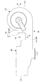
- FIG. 3 is a view showing a configuration of a fan unit of the blower, and is a cross-sectional view taken along the line AA of FIG. It is a longitudinal cross-sectional view of the chamber of the said air blower. It is a longitudinal cross-sectional view of the chamber in the modification of the air blower which concerns on this embodiment.
- FIG. 1 is a plan view showing the internal structure of the air blower according to the present embodiment.
- FIG. 2 is a bottom view of the blower.
- FIG. 3 is a view showing a configuration of a fan portion of the blower, and is a cross-sectional view taken along the line AA of FIG.
- FIG. 4 is a plan sectional view showing the chamber of the blower.
- FIG. 5 is a longitudinal sectional view of the chamber.
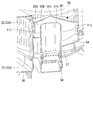
- the air blower 10 which comprises the air conditioning apparatus for vehicles is provided in the hollow casing 11 and the end 11a side of the casing 11, and the fan part 20 which produces a wind, and a fan part A discharge nozzle portion 30 for discharging the air generated at 20, a heat exchanger accommodating portion 40 provided on the other end 11b side of the casing 11 and accommodating the evaporator 41, and a motor cooling portion 50 are provided.
- the casing 11 has an upper and lower split structure, and the upper and lower bottom casings 11A and 11B are combined with each other in the vertical direction. It is formed by connecting.
- the fan unit 20 is formed in the motor 21 (see FIG. 3), the scroll fan 22 provided in the casing 11 and rotationally driven by the motor 21, and the upper casing 11A.
- An air inlet 23 (see FIG. 3) and a scroll passage portion 24 formed radially outward of the scroll fan 22 in the casing 11 are provided.
- the motor 21 has a motor body 21a fitted and held in a motor holding opening 13 formed in the bottom plate portion 11c of the lower casing 11B, and a motor shaft rotationally driven about its axis by the motor body 21a. And 21b.
- the motor 21 is provided in a state in which the motor shaft 21b is protruded upward from the bottom plate portion 11c of the lower casing 11B.
- the scroll fan 22 is provided integrally with the motor shaft 21b above the bottom plate portion 11c of the lower casing 11B.
- the scroll fan 22 has a cylindrical shape provided around the motor shaft 21b, and includes a plurality of blades 22a provided on the outer peripheral portion thereof at intervals in the circumferential direction.
- the scroll fan 22 is rotationally driven integrally with the motor shaft 21 b by the motor 21, and takes in external air from the air intake 23 formed in the upper casing 11 A radially inward of the scroll fan 22. Send radially outward.
- the scroll flow passage portion 24 is continuously formed in the circumferential direction on the radially outer side of the scroll fan 22.
- the scroll flow passage portion 24 is formed such that the flow passage cross-sectional area thereof gradually increases as it goes to the downstream side in the air flow direction along the circumferential direction.
- the discharge nozzle portion 30 has a discharge flow passage portion 31 which is formed in the casing 11 and linearly extends in a tangential direction from the downstream end of the scroll flow passage portion 24 of the fan portion 20. The air fed from the scroll flow passage portion 24 is guided to the downstream side.
- the heat exchanger accommodating portion 40 includes an evaporator 41 accommodated in the casing 11.
- the evaporator 41 is disposed such that the one surface side 41 a thereof is directed to the downstream end 31 b side of the discharge flow passage portion 31 of the discharge nozzle portion 30.
- an air discharge port 14 communicating the inside and the outside of the casing 11 is formed in a portion facing the other surface side 41 b of the evaporator 41.
- the air sent out from the scroll flow path portion 24 and sent in through the discharge flow path portion 31 passes from the one surface side 41 a of the evaporator 41 to the other surface side 41 b.
- Exchange heat with the refrigerant flowing through the The air after heat exchange via the evaporator 41 is discharged from the air discharge port 14 of the casing 11 to the outside of the casing 11.
- the motor cooling unit 50 cools the motor main body 21 a of the motor 21 that rotationally drives the scroll fan 22 of the fan unit 20.
- the motor cooling unit 50 includes a chamber 51 for taking in air from the discharge flow passage 31 of the discharge nozzle unit 30, and a cooling duct 52 for feeding air from the inside of the chamber 51 toward the motor main body 21a.
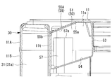
- the chamber 51 is a portion sandwiched between the discharge flow passage 31 and the scroll flow passage 24. Is formed. Specifically, in the casing 11, the chamber 51 has an outer peripheral wall 11 s located radially outward of the scroll flow passage 24, a side wall 11 t located on one side in the width direction of the discharge flow passage 31, and an outer peripheral wall A flat L-shaped L-shaped wall 53 extending outward from the outer surface of 11s and connected to the outer surface of the side wall 11t, a bottom plate 54 formed on the lower casing 11B, and a ceiling formed on the upper casing 11A It is formed by being surrounded by 55A.
- the chamber 51 is in communication with the discharge flow passage 31 through a communication opening 56 formed in the side wall 11 t, and a part of the air flowing through the discharge flow passage 31 flows into the chamber 51 from the communication opening 56.
- the cooling duct 52 protrudes upward from the bottom plate portion 54 of the chamber 51, and has a cylindrical suction nozzle 57 having an opening 57 a opening vertically upward in the chamber 51, and the suction nozzle 57. And a cylindrical guide passage portion 58 provided along the lower side of the bottom plate portion 11c of the lower casing 11B.
- the guide passage portion 58 includes a spray nozzle 58a for blowing air to the motor main body 21a which protrudes downward from the bottom plate portion 11c of the lower casing 11B.
- the air flowing into the chamber 51 from the discharge flow passage 31 through the communication opening 56 is fed to the suction nozzle 57 from the opening 57 a opened in the chamber 51.
- the air fed into the suction nozzle 57 passes through the guide flow passage portion 58, and is blown to the motor body 21a by the spray nozzle 58a to cool the motor body 21a.
- the ceiling 55A of the chamber 51 is an inclined surface inclined obliquely downward from one end 55a to the other end 55b. It is formed to have 59.
- the inclined surface 59 is formed at least in a region including the vertically upper portion of the opening 57a of the suction nozzle 57 in the ceiling 55A.
- the position of the end 55a in the upper side in the inclination direction and the position of the end 55b in the lower side in the inclination direction are not limited at all.
- the communication opening 56 side may be an end 55b which is lower in the inclination direction, and a side farther from the communication opening 56 may be an end 55a which is upper in the inclination direction.
- the water droplets adhere to the ceiling portion 55A of the chamber 51 due to moisture or the like contained in the air taken into the chamber 51 by the inclined surfaces 59, the water droplets are drawn along the inclined surfaces 59 from above along the inclined direction. It flows down and down. In this embodiment, the water droplets flowing downward along the inclined surface 59 are discharged from the communication opening 56 to the discharge flow passage portion 31.
- the blower 10 has the chamber 51 for taking in part of the air from the discharge flow passage portion 31 and the opening 57a opened in the chamber 51, and the chamber taken in from the opening 57a. And a cooling duct 52 for feeding the air in the motor 51 to the motor 21.
- the ceiling 55A of the chamber 51 has an inclined surface 59 which is inclined downward from above.
- the inclined surface 59 at least vertically above the opening 57a, it is possible to more reliably prevent water droplets from falling into the opening 57a.
- the vehicle air conditioning apparatus (not shown) equipped with the air blower 10 according to the present embodiment, by providing the inclined surface 59 on the ceiling 55A of the air blower 10, the water droplets can be removed from the motor cooling portion 50. Entry into the cooling duct 52 from the opening 57 a can be suppressed, and reaching the motor 21 can be prevented.
- FIG. 5 is a longitudinal cross-sectional view of a chamber in a modification of the air blower according to the present embodiment.
- the ceiling portion 55B of the chamber 51 has an umbrella shape extending obliquely downward from the central portion 55c of the ceiling portion 55B in a plan view toward the outer peripheral end 55d radially outward. It may be formed by the inclined surface 60 of
- the ceiling portion 55B of the chamber 51 has the beveled inclined surface 60, when water droplets adhere to the ceiling portion 55B, the water droplets are directed outward in the radial direction of the ceiling portion 55B. It can lead. Thus, the water droplets can be prevented from entering the cooling duct 52 from the opening 57 a of the motor cooling unit 50 and can be prevented from reaching the motor 21.
Landscapes
- Engineering & Computer Science (AREA)
- Mechanical Engineering (AREA)
- General Engineering & Computer Science (AREA)
- Physics & Mathematics (AREA)
- Thermal Sciences (AREA)
- Structures Of Non-Positive Displacement Pumps (AREA)
- Air-Conditioning For Vehicles (AREA)
Abstract
本発明は、モータ冷却のため、流路部から空気の一部を取り込むチャンバを備えた送風装置、車両用空気調和装置において、モータへの水滴の到達を、より確実に防止する。 空気取入口(23)、空気吐出口、及び空気取入口(23)と空気吐出口とを連通する吐出流路部(31)を備えたケーシング(11)と、ケーシング(11)内に設けられ、空気取入口(23)から空気を取り込み、吐出流路部(31)を介して空気吐出口へと至る空気の流れを生成するスクロールファン(22)と、スクロールファン(22)を回転駆動させるモータ(21)と、モータ(21)を冷却するモータ冷却部(50)と、を備え、モータ冷却部(50)は、吐出流路部(31)から空気の一部を取り込むチャンバ(51)と、一端にチャンバ(51)内で開口した開口部(57a)を有し、開口部(57a)から取り込んだチャンバ(51)内の空気をモータ(21)に送給する冷却ダクト(52)と、を備え、チャンバ(51)の天井部(55A) は、上方から下方に向かって傾斜した傾斜面(59)を備えている。
Description
本発明は、送風装置、車両用空気調和装置に関するものである。
車両用の空調装置等の送風装置として、ケーシングと、スクロールファンと、スクロールファンを回転駆動するモータと、を備えた構成のものがある。このような送風装置は、モータによって回転駆動されるスクロールファンによって、ケーシングに形成された空気取入口からスクロールファンの中心部に空気を取り込む。取り込まれた空気は、回転するスクロールファンによってその径方向外側に吹き出され、スクロールファンの径方向外側に形成されたスクロール流路を通り、下流側の吐出ノズルを経て吐出される。
このような送風装置において、スクロールファンから吐出された空気の一部をチャンバに取り込み、このチャンバ内に一端が開口したダクトを通してモータに空気を送り込むことによって、スクロールファンを回転駆動するモータを冷却することが行われている。
ところで、空気取入口からケーシング内に取り込んだ空気中には、水分が含まれていることがある。この水分がダクトを通ってモータに到達すると、モータの作動に悪影響が及ぶ可能性がある。
ところで、空気取入口からケーシング内に取り込んだ空気中には、水分が含まれていることがある。この水分がダクトを通ってモータに到達すると、モータの作動に悪影響が及ぶ可能性がある。
そこで、例えば特許文献1には、吐出ノズルからチャンバ内に空気を取り込む空気取入口に段差を形成することで、チャンバ内への水滴の侵入を防止する構成が開示されている。
しかしながら、例えば特許文献1に開示されたような構成においても、空気中に含まれる水分(水滴)を十分に回収することができない場合があり、モータへの水滴の到達を、より確実に防止することが望まれている。
本発明は、このような事情に鑑みてなされたものであって、モータへの水滴の到達を、より確実に防止することができる送風装置、車両用空気調和装置を提供することを目的とする。
上記課題を解決するために、本発明の送風装置、車両用空気調和装置は以下の手段を採用する。
本発明に係る送風装置は、空気取入口、空気吐出口、及び前記空気取入口と前記空気吐出口とを連通する流路部を備えたケーシングと、前記ケーシング内に設けられて前記空気取入口から空気を取り込み、前記流路部を介して前記空気吐出口へと至る空気の流れを生成するファンと、前記ファンを回転駆動させるモータと、前記モータを冷却するモータ冷却部と、を備え、前記モータ冷却部は、前記流路部から前記空気の一部を取り込むチャンバと、前記チャンバ内で開口した開口部を有し、前記開口部から取り込んだ前記チャンバ内の空気を前記モータに送給するダクトと、を備え、前記チャンバの天井部は、上方から下方に向かって傾斜した傾斜面を備えている。
本発明に係る送風装置は、空気取入口、空気吐出口、及び前記空気取入口と前記空気吐出口とを連通する流路部を備えたケーシングと、前記ケーシング内に設けられて前記空気取入口から空気を取り込み、前記流路部を介して前記空気吐出口へと至る空気の流れを生成するファンと、前記ファンを回転駆動させるモータと、前記モータを冷却するモータ冷却部と、を備え、前記モータ冷却部は、前記流路部から前記空気の一部を取り込むチャンバと、前記チャンバ内で開口した開口部を有し、前記開口部から取り込んだ前記チャンバ内の空気を前記モータに送給するダクトと、を備え、前記チャンバの天井部は、上方から下方に向かって傾斜した傾斜面を備えている。
本発明に係る送風装置によれば、モータによって回転駆動されるファンによって空気取入口からケーシング内に取り込まれた空気は、流路部に送り出される。流路部を流れる空気の一部はチャンバ内に取り込まれ、開口部からダクトを通してモータに供給され、モータを冷却する。チャンバ内に取り込まれた空気に含まれる水分等によってチャンバの天井部に水滴が付着した場合、天井部の傾斜面が傾斜しているため、水滴は、傾斜面の傾斜方向に沿って上方から下方に伝って流れる。これにより、水滴がモータ冷却部の開口部からダクトに入り込むのを抑えることができる。
上記送風装置において、前記傾斜面は、少なくとも前記開口部の鉛直上方に形成されているとさらに好適である。
このような送風装置によれば、傾斜面を少なくとも開口部の鉛直上方に形成することで、水滴が開口部に落ちるのを、より確実に防止することができる。
上記送風装置において、前記傾斜面は、前記天井部の中央部から径方向外側に向かって漸次下方に傾斜した傘状に形成されているとさらに好適である。
このような送風装置によれば、天井部に水滴が付着した場合、水滴を天井部の径方向外側の壁面に向かって導くことができる。
本発明に係る車両用空気調和装置は、上記いずれかの送風装置を具備している。
本発明に係る車両用空気調和装置によれば、送風装置において天井部に傾斜面を備えることで、水滴がモータ冷却部に入り込むのを抑え、モータに到達するのを防止することができる。
本発明に係る送風装置、車両用空気調和装置によれば、モータへの水滴の到達を、より確実に防止することができる。
以下に、本発明に係る送風装置、車両用空気調和装置の一実施形態について、図面を参照して説明する。
図1は、本実施形態に係る送風装置の内部構造を示す平面図である。図2は、上記送風装置の底面図である。図3は、上記送風装置のファン部の構成を示す図であり、図2のA-A矢視断面図である。図4は、上記送風装置のチャンバを示す平断面図である。図5は、上記チャンバの縦断面図である。
図1は、本実施形態に係る送風装置の内部構造を示す平面図である。図2は、上記送風装置の底面図である。図3は、上記送風装置のファン部の構成を示す図であり、図2のA-A矢視断面図である。図4は、上記送風装置のチャンバを示す平断面図である。図5は、上記チャンバの縦断面図である。
(送風装置)
図1、図2に示すように、車両用空気調和装置を構成する送風装置10は、中空のケーシング11と、ケーシング11の一端11a側に設けられ、風を生成するファン部20と、ファン部20で生成した風を吐出する吐出ノズル部30と、ケーシング11の他端11b側に設けられ、エバポレータ41を収容した熱交換器収容部40と、モータ冷却部50と、を備えている。
図1、図2に示すように、車両用空気調和装置を構成する送風装置10は、中空のケーシング11と、ケーシング11の一端11a側に設けられ、風を生成するファン部20と、ファン部20で生成した風を吐出する吐出ノズル部30と、ケーシング11の他端11b側に設けられ、エバポレータ41を収容した熱交換器収容部40と、モータ冷却部50と、を備えている。
図3に示すように、ケーシング11は、上下2分割構造で、上方に開口した有底状の上部ケーシング11Aと、下方に開口した有底状の下部ケーシング11Bとを、上下方向に組み合わせて互いに連結することで形成されている。
(ファン部)
図1、図3に示すように、ファン部20は、モータ21(図3参照)と、ケーシング11内に設けられ、モータ21によって回転駆動されるスクロールファン22と、上部ケーシング11Aに形成された空気取入口23(図3参照)と、ケーシング11内においてスクロールファン22の径方向外側に形成されたスクロール流路部24と、を備えている。
図1、図3に示すように、ファン部20は、モータ21(図3参照)と、ケーシング11内に設けられ、モータ21によって回転駆動されるスクロールファン22と、上部ケーシング11Aに形成された空気取入口23(図3参照)と、ケーシング11内においてスクロールファン22の径方向外側に形成されたスクロール流路部24と、を備えている。
図3に示すように、モータ21は、下部ケーシング11Bの底板部11cに形成されたモータ保持開口13に嵌合保持されたモータ本体21aと、モータ本体21aによって軸周りに回転駆動されるモータ軸21bと、を備えている。モータ21は、モータ軸21bを下部ケーシング11Bの底板部11cから上方に向かって突出させた状態で設けられている。
スクロールファン22は、下部ケーシング11Bの底板部11cの上方に、モータ軸21bに一体に連結されて設けられている。スクロールファン22は、モータ軸21bを中心として設けられた円筒状で、その外周部に、周方向に間隔をあけて設けられた複数枚のブレード22aを備えている。このようなスクロールファン22は、モータ21によってモータ軸21bと一体に回転駆動され、上部ケーシング11Aに形成された空気取入口23から外部の空気をスクロールファン22の径方向内側に取り込み、スクロールファン22の径方向外側に送り出す。
図1に示すように、スクロール流路部24は、スクロールファン22の径方向外側において、周方向に連続して形成されている。スクロール流路部24は、周方向に沿って空気の流れ方向下流側に向かうにしたがって、その流路断面積が漸次増大するよう形成されている。
(吐出ノズル部)
吐出ノズル部30は、ケーシング11内に形成されて、ファン部20のスクロール流路部24の下流端から接線方向に直線状に延びる吐出流路部31を有し、この吐出流路部31を通してスクロール流路部24から送り込まれる空気を下流側に導く。
吐出ノズル部30は、ケーシング11内に形成されて、ファン部20のスクロール流路部24の下流端から接線方向に直線状に延びる吐出流路部31を有し、この吐出流路部31を通してスクロール流路部24から送り込まれる空気を下流側に導く。
(熱交換器収容部)
熱交換器収容部40は、ケーシング11内に収容したエバポレータ41を備えている。エバポレータ41は、その一面側41aを、吐出ノズル部30の吐出流路部31の下流端31b側に向けて配置されている。また、ケーシング11には、エバポレータ41の他面側41bに対向する部位に、ケーシング11の内外を連通する空気吐出口14が形成されている。
このような熱交換器収容部40は、スクロール流路部24から送り出されて吐出流路部31を通して送り込まれた空気が、エバポレータ41の一面側41aから他面側41bに通過し、エバポレータ41内を流れる冷媒と熱交換する。エバポレータ41を経て熱交換後の空気は、ケーシング11の空気吐出口14からケーシング11の外部に吐出される。
(モータ冷却部)
図3に示すように、モータ冷却部50は、ファン部20のスクロールファン22を回転駆動するモータ21のモータ本体21aを冷却する。このモータ冷却部50は、吐出ノズル部30の吐出流路部31から空気を取り込むチャンバ51と、チャンバ51内からモータ本体21aに向かって空気を送り込む冷却ダクト52と、を備えている。
図3に示すように、モータ冷却部50は、ファン部20のスクロールファン22を回転駆動するモータ21のモータ本体21aを冷却する。このモータ冷却部50は、吐出ノズル部30の吐出流路部31から空気を取り込むチャンバ51と、チャンバ51内からモータ本体21aに向かって空気を送り込む冷却ダクト52と、を備えている。
図1、図3、図4に示すように、チャンバ51は、吐出ノズル部30の吐出流路部31の上流部31aにおいて、吐出流路部31とスクロール流路部24とに挟まれた部分に形成されている。具体的には、チャンバ51は、ケーシング11において、スクロール流路部24の径方向外側に位置する外周壁11sと、吐出流路部31の幅方向一方の側に位置する側壁11tと、外周壁11sの外面から外方に延び、側壁11tの外面に接続される平面視L字状のL字壁53と、下部ケーシング11Bに形成された底板部54と、上部ケーシング11Aに形成された天井部55Aと、によって囲まれて形成されている。
また、チャンバ51は、側壁11tに形成された連通開口56を介して吐出流路部31に連通し、この連通開口56から吐出流路部31を流れる空気の一部がチャンバ51内に流れ込む。
図3に示すように、冷却ダクト52は、チャンバ51の底板部54から上方に突出し、チャンバ51内で鉛直上方を向いて開口した開口部57aを有する筒状の吸込ノズル57と、吸込ノズル57に連続し、下部ケーシング11Bの底板部11cの下方に沿って設けられた筒状の案内流路部58と、を備えている。案内流路部58は、下部ケーシング11Bの底板部11cから下方に突出したモータ本体21aに空気を吹き付ける吹付ノズル58aを備えている。
このようなモータ冷却部50は、吐出流路部31から連通開口56を通してチャンバ51内に流れ込んだ空気が、チャンバ51内で開口した開口部57aから吸込ノズル57に送り込まれる。吸込ノズル57に送り込まれた空気は、案内流路部58を経て、吹付ノズル58aによってモータ本体21aに吹き付けられ、モータ本体21aを冷却する。
図3、図4に示すように、上記のようなモータ冷却部50において、チャンバ51の天井部55Aは、一方の端部55aから他方の端部55bに向かって、斜め下方に傾斜した傾斜面59を有して形成されている。傾斜面59は、少なくとも、天井部55Aにおいて吸込ノズル57の開口部57aの鉛直上方を含む領域に形成されている。
ここで、天井部55Aの傾斜面59において、傾斜方向上方となる端部55aの位置、傾斜方向下方となる端部55bの位置は、何ら限定するものではない。例えば、天井部55Aは、連通開口56側を、傾斜方向下方となる端部55bとし、連通開口56から遠い側を傾斜方向上方となる端部55aとしてもよい。
この傾斜面59により、チャンバ51内に取り込まれた空気に含まれる水分等によって、チャンバ51の天井部55Aに水滴が付着した場合、水滴は、傾斜面59に沿って傾斜方向に沿って上方から下方に伝って流れる。この実施形態において、傾斜面59に沿って下方に流した水滴は、連通開口56から吐出流路部31に排出するものとする。
ここで、天井部55Aの傾斜面59において、傾斜方向上方となる端部55aの位置、傾斜方向下方となる端部55bの位置は、何ら限定するものではない。例えば、天井部55Aは、連通開口56側を、傾斜方向下方となる端部55bとし、連通開口56から遠い側を傾斜方向上方となる端部55aとしてもよい。
この傾斜面59により、チャンバ51内に取り込まれた空気に含まれる水分等によって、チャンバ51の天井部55Aに水滴が付着した場合、水滴は、傾斜面59に沿って傾斜方向に沿って上方から下方に伝って流れる。この実施形態において、傾斜面59に沿って下方に流した水滴は、連通開口56から吐出流路部31に排出するものとする。
上述したような構成によれば、送風装置10は、吐出流路部31から空気の一部を取り込むチャンバ51と、チャンバ51内で開口した開口部57aを有し、開口部57aから取り込んだチャンバ51内の空気をモータ21に送給する冷却ダクト52と、を備えるモータ冷却部50を具備し、チャンバ51の天井部55Aは、上方から下方に向かって傾斜した傾斜面59を備えている。これにより、チャンバ51内に取り込まれた空気に含まれる水分等によって、チャンバ51の天井部55Aに水滴が付着した場合、天井部55Aに傾斜面59が形成されているので、水滴は、傾斜面59の傾斜方向に沿って上方から下方に伝って流れる。これにより、水滴がモータ冷却部50の開口部57aから冷却ダクト52に入り込むのを抑え、モータ21に到達するのを防止することができる。
また、傾斜面59を少なくとも開口部57aの鉛直上方に形成することで、水滴が開口部57aに落ちるのを、より確実に防止することができる。
また、本実施形態に係る送風装置10を具備した車両用空気調和装置(図示せず)によれば、送風装置10の天井部55Aに傾斜面59を備えることで、水滴がモータ冷却部50の開口部57aから冷却ダクト52に入り込むのを抑え、モータ21に到達するのを防止することができる。
〔実施形態の変形例〕
上記実施形態においては、チャンバ51の天井部55Aを、一方の端部55aから他方の端部55bに向かって、斜め下方に傾斜するようにしたが、これに限らない。
図5は、本実施形態に係る送風装置の変形例におけるチャンバの縦断面図である。
例えば、図5に示すように、チャンバ51の天井部55Bは、平面視した状態における天井部55Bの中央部55cから径方向外側の外周端部55dに向かって斜め下方に傾斜して延びる傘状の傾斜面60によって形成してもよい。
上記実施形態においては、チャンバ51の天井部55Aを、一方の端部55aから他方の端部55bに向かって、斜め下方に傾斜するようにしたが、これに限らない。
図5は、本実施形態に係る送風装置の変形例におけるチャンバの縦断面図である。
例えば、図5に示すように、チャンバ51の天井部55Bは、平面視した状態における天井部55Bの中央部55cから径方向外側の外周端部55dに向かって斜め下方に傾斜して延びる傘状の傾斜面60によって形成してもよい。
このような構成においても、チャンバ51の天井部55Bが、傘状の傾斜面60を有しているため、天井部55Bに水滴が付着した場合、水滴を天井部55Bの径方向外側に向かって導くことができる。これにより、水滴がモータ冷却部50の開口部57aから冷却ダクト52に入り込むのを抑え、モータ21に到達するのを防止することができる。
なお、上記実施形態において、送風装置10の構成について示したが、本発明の主旨を逸脱しない範囲であれば、各部の構成を適宜変更してもよい。
10 送風装置
11 ケーシング
14 空気吐出口
21 モータ
22 スクロールファン(ファン)
23 空気取入口
31 吐出流路部(流路部)
50 モータ冷却部
51 チャンバ
52 冷却ダクト(ダクト)
55A、55B 天井部
57a 開口部
58 案内流路部
58a 吹付ノズル部
59,60 傾斜面
11 ケーシング
14 空気吐出口
21 モータ
22 スクロールファン(ファン)
23 空気取入口
31 吐出流路部(流路部)
50 モータ冷却部
51 チャンバ
52 冷却ダクト(ダクト)
55A、55B 天井部
57a 開口部
58 案内流路部
58a 吹付ノズル部
59,60 傾斜面
Claims (4)
- 空気取入口、空気吐出口、及び前記空気取入口と前記空気吐出口とを連通する流路部を備えたケーシングと、
前記空気取入口から空気を取り込み、前記流路部を介して前記空気吐出口へと至る空気の流れを生成するファンと、
前記ファンを回転駆動させるモータと、
前記モータを冷却するモータ冷却部と、を備え、
前記モータ冷却部は、前記流路部から前記空気の一部を取り込むチャンバと、
前記チャンバ内で開口した開口部を有し、前記開口部から取り込んだ前記チャンバ内の前記空気を前記モータに送給するダクトと、を備え、
前記チャンバの天井部は、上方から下方に向かって傾斜した傾斜面を備えていることを特徴とする送風装置。 - 前記傾斜面は、少なくとも前記開口部の鉛直上方に形成されていることを特徴とする請求項1に記載の送風装置。
- 前記傾斜面は、前記天井部の中央部から径方向外側に向かって漸次下方に傾斜した傘状に形成されていることを特徴とする請求項1又は2に記載の送風装置。
- 請求項1から3のいずれか一項に記載の送風装置を具備していることを特徴とする車両用空気調和装置。
Priority Applications (4)
| Application Number | Priority Date | Filing Date | Title |
|---|---|---|---|
| CN201780028614.2A CN109562670B (zh) | 2016-07-15 | 2017-07-06 | 送风装置、车辆用空气调节装置 |
| US16/092,641 US20190170159A1 (en) | 2016-07-15 | 2017-07-06 | Blower device and vehicular air-conditioning device |
| DE112017003590.2T DE112017003590T5 (de) | 2016-07-15 | 2017-07-06 | Gebläsevorrichtung und fahrzeugklimaanlage |
| US17/176,458 US11629724B2 (en) | 2016-07-15 | 2021-02-16 | Blower device and vehicular air-conditioning device |
Applications Claiming Priority (2)
| Application Number | Priority Date | Filing Date | Title |
|---|---|---|---|
| JP2016-140550 | 2016-07-15 | ||
| JP2016140550A JP6873622B2 (ja) | 2016-07-15 | 2016-07-15 | 送風装置、車両用空気調和装置 |
Related Child Applications (2)
| Application Number | Title | Priority Date | Filing Date |
|---|---|---|---|
| US16/092,641 A-371-Of-International US20190170159A1 (en) | 2016-07-15 | 2017-07-06 | Blower device and vehicular air-conditioning device |
| US17/176,458 Division US11629724B2 (en) | 2016-07-15 | 2021-02-16 | Blower device and vehicular air-conditioning device |
Publications (1)
| Publication Number | Publication Date |
|---|---|
| WO2018012410A1 true WO2018012410A1 (ja) | 2018-01-18 |
Family
ID=60952881
Family Applications (1)
| Application Number | Title | Priority Date | Filing Date |
|---|---|---|---|
| PCT/JP2017/024877 WO2018012410A1 (ja) | 2016-07-15 | 2017-07-06 | 送風装置、車両用空気調和装置 |
Country Status (5)
| Country | Link |
|---|---|
| US (2) | US20190170159A1 (ja) |
| JP (1) | JP6873622B2 (ja) |
| CN (1) | CN109562670B (ja) |
| DE (1) | DE112017003590T5 (ja) |
| WO (1) | WO2018012410A1 (ja) |
Families Citing this family (2)
| Publication number | Priority date | Publication date | Assignee | Title |
|---|---|---|---|---|
| WO2021070356A1 (ja) * | 2019-10-11 | 2021-04-15 | 三菱重工サーマルシステムズ株式会社 | 車両用空調装置 |
| KR102292952B1 (ko) * | 2019-11-21 | 2021-08-23 | 덴소코리아 주식회사 | 차량의 이층류 공조기용 송풍장치 |
Citations (4)
| Publication number | Priority date | Publication date | Assignee | Title |
|---|---|---|---|---|
| JPS6121817A (ja) * | 1984-07-09 | 1986-01-30 | Hitachi Ltd | 自動車用ブロワ装置 |
| JP2007001541A (ja) * | 2005-06-27 | 2007-01-11 | Denso Corp | 送風装置およびこれを備えた車両用空調装置 |
| JP2009525434A (ja) * | 2006-02-01 | 2009-07-09 | ロベルト・ボッシュ・ゲゼルシャフト・ミト・ベシュレンクテル・ハフツング | 遠心ブロワー |
| JP2011252478A (ja) * | 2010-06-04 | 2011-12-15 | Mitsubishi Heavy Ind Ltd | 多翼遠心ファンおよびそれを用いた車両用空調装置 |
Family Cites Families (24)
| Publication number | Priority date | Publication date | Assignee | Title |
|---|---|---|---|---|
| JP3426151B2 (ja) * | 1998-03-16 | 2003-07-14 | アスモ株式会社 | ブラシレスモータ |
| JP2000043532A (ja) * | 1998-07-29 | 2000-02-15 | Denso Corp | 空調装置 |
| JP4273576B2 (ja) | 1999-06-04 | 2009-06-03 | 株式会社デンソー | 車両用空調装置 |
| JP2001180248A (ja) | 1999-12-24 | 2001-07-03 | Denso Corp | 車両用空調装置 |
| JP4185654B2 (ja) * | 2000-08-04 | 2008-11-26 | カルソニックカンセイ株式会社 | 遠心式の多翼送風機 |
| JP4016690B2 (ja) | 2001-07-04 | 2007-12-05 | 株式会社デンソー | 車両用空調装置 |
| KR100651684B1 (ko) * | 2002-05-10 | 2006-11-30 | 한라공조주식회사 | 송풍기 모우터의 냉각장치 |
| FR2856852B1 (fr) * | 2003-06-27 | 2006-09-29 | Asmo Co Ltd | Ensemble moteur pour climatiseur pour vehicules |
| JP2005168268A (ja) * | 2003-12-05 | 2005-06-23 | Asmo Co Ltd | モータの駆動回路装置、及びモータ |
| US7118355B2 (en) * | 2005-02-04 | 2006-10-10 | Delphi Technologies, Inc. | Electric motor driven blower assembly with integral motor cooling duct |
| JP4876841B2 (ja) * | 2005-12-28 | 2012-02-15 | 株式会社デンソー | 送風装置 |
| FR2899654B1 (fr) * | 2006-04-10 | 2008-07-04 | Valeo Systemes Thermiques | Canal de refroidissement pour un moteur de ventilateur d'un systeme de ventilation, chauffage et/ou de climatisation |
| JP4830899B2 (ja) * | 2007-02-20 | 2011-12-07 | 株式会社デンソー | 送風機 |
| JP5157762B2 (ja) | 2008-09-02 | 2013-03-06 | 株式会社デンソー | 送風装置 |
| US8267674B2 (en) * | 2010-02-04 | 2012-09-18 | Robert Bosch Gmbh | Centrifugal blower assembly |
| JP5859427B2 (ja) * | 2010-03-15 | 2016-02-10 | 株式会社ヴァレオジャパン | 車両用空調ユニット |
| JP6088753B2 (ja) * | 2012-06-13 | 2017-03-01 | サンデンホールディングス株式会社 | 車両用空気調和装置 |
| WO2014125710A1 (ja) * | 2013-02-12 | 2014-08-21 | 三菱電機株式会社 | 車両用空気調和装置の室外冷却ユニット |
| JP6098504B2 (ja) | 2013-12-26 | 2017-03-22 | 株式会社デンソー | 車両用空調装置 |
| JP6354309B2 (ja) * | 2014-05-12 | 2018-07-11 | 株式会社デンソー | ブロワ装置 |
| US9647894B2 (en) | 2014-07-30 | 2017-05-09 | International Business Machines Corporation | Mapping relationships among virtual elements across a system |
| CN204786776U (zh) * | 2015-06-08 | 2015-11-18 | 广东美的制冷设备有限公司 | 空调器室内机及具有其的空调器 |
| DE102015113785B4 (de) * | 2015-08-20 | 2018-11-29 | Halla Visteon Climate Control Corporation | Kühlluftschnittstelle in einem Gebläsegehäuse |
| JP6260838B2 (ja) * | 2016-02-29 | 2018-01-17 | 株式会社ケーヒン | 空調用ブロアモータユニット |
-
2016
- 2016-07-15 JP JP2016140550A patent/JP6873622B2/ja active Active
-
2017
- 2017-07-06 WO PCT/JP2017/024877 patent/WO2018012410A1/ja active Application Filing
- 2017-07-06 DE DE112017003590.2T patent/DE112017003590T5/de active Pending
- 2017-07-06 CN CN201780028614.2A patent/CN109562670B/zh active Active
- 2017-07-06 US US16/092,641 patent/US20190170159A1/en not_active Abandoned
-
2021
- 2021-02-16 US US17/176,458 patent/US11629724B2/en active Active
Patent Citations (4)
| Publication number | Priority date | Publication date | Assignee | Title |
|---|---|---|---|---|
| JPS6121817A (ja) * | 1984-07-09 | 1986-01-30 | Hitachi Ltd | 自動車用ブロワ装置 |
| JP2007001541A (ja) * | 2005-06-27 | 2007-01-11 | Denso Corp | 送風装置およびこれを備えた車両用空調装置 |
| JP2009525434A (ja) * | 2006-02-01 | 2009-07-09 | ロベルト・ボッシュ・ゲゼルシャフト・ミト・ベシュレンクテル・ハフツング | 遠心ブロワー |
| JP2011252478A (ja) * | 2010-06-04 | 2011-12-15 | Mitsubishi Heavy Ind Ltd | 多翼遠心ファンおよびそれを用いた車両用空調装置 |
Also Published As
| Publication number | Publication date |
|---|---|
| DE112017003590T5 (de) | 2019-05-23 |
| CN109562670B (zh) | 2022-05-03 |
| US20210164480A1 (en) | 2021-06-03 |
| JP2018008659A (ja) | 2018-01-18 |
| CN109562670A (zh) | 2019-04-02 |
| JP6873622B2 (ja) | 2021-05-19 |
| US20190170159A1 (en) | 2019-06-06 |
| US11629724B2 (en) | 2023-04-18 |
Similar Documents
| Publication | Publication Date | Title |
|---|---|---|
| JP2020076355A (ja) | 軸流ブロワ | |
| KR101848717B1 (ko) | 송풍 장치 | |
| US11629724B2 (en) | Blower device and vehicular air-conditioning device | |
| JP2016018203A (ja) | 撮像装置 | |
| CN105102824B (zh) | 单侧吸入式离心风机 | |
| US20160229262A1 (en) | Vehicle air-conditioning apparatus | |
| WO2015025498A1 (ja) | 送風機 | |
| JP2011058728A (ja) | 液体微細化ユニットおよび液体微細化装置とそれを用いたサウナ装置 | |
| KR101211520B1 (ko) | 자동차 공기조화장치용 송풍장치 | |
| US20180105012A1 (en) | Air conditioner for vehicle | |
| US10328766B2 (en) | Rooftop-mounted air-conditioning installation | |
| JP2010059825A (ja) | 送風装置 | |
| KR20140054655A (ko) | 차량용 공조장치의 송풍기 | |
| JP2011252478A (ja) | 多翼遠心ファンおよびそれを用いた車両用空調装置 | |
| JP2018008659A5 (ja) | ||
| JP2019089408A (ja) | 車両用空調装置 | |
| JP2006298180A (ja) | ブロワモータ冷却構造 | |
| KR100971196B1 (ko) | 자동차 송풍장치용 인렛링 | |
| JP7187285B2 (ja) | 車両用空調装置 | |
| JP2018128221A (ja) | 冷却装置 | |
| KR101094841B1 (ko) | 자동차 공조 장치용 송풍기 | |
| JP2018100622A (ja) | 送風装置 | |
| JP2018140651A (ja) | 自動車の空調装置 | |
| JP6211101B2 (ja) | 遠心ファン、空気調和装置及び空気清浄装置 | |
| JPWO2015140963A1 (ja) | 遠心送風機 |
Legal Events
| Date | Code | Title | Description |
|---|---|---|---|
| 121 | Ep: the epo has been informed by wipo that ep was designated in this application |
Ref document number: 17827538 Country of ref document: EP Kind code of ref document: A1 |
|
| 122 | Ep: pct application non-entry in european phase |
Ref document number: 17827538 Country of ref document: EP Kind code of ref document: A1 |