WO2018012202A1 - ガラス部材の製造方法 - Google Patents
ガラス部材の製造方法 Download PDFInfo
- Publication number
- WO2018012202A1 WO2018012202A1 PCT/JP2017/022436 JP2017022436W WO2018012202A1 WO 2018012202 A1 WO2018012202 A1 WO 2018012202A1 JP 2017022436 W JP2017022436 W JP 2017022436W WO 2018012202 A1 WO2018012202 A1 WO 2018012202A1
- Authority
- WO
- WIPO (PCT)
- Prior art keywords
- powder
- glass
- mixing
- mixture
- firing
- Prior art date
- Legal status (The legal status is an assumption and is not a legal conclusion. Google has not performed a legal analysis and makes no representation as to the accuracy of the status listed.)
- Ceased
Links
Images

Classifications
-
- C—CHEMISTRY; METALLURGY
- C03—GLASS; MINERAL OR SLAG WOOL
- C03B—MANUFACTURE, SHAPING, OR SUPPLEMENTARY PROCESSES
- C03B19/00—Other methods of shaping glass
- C03B19/06—Other methods of shaping glass by sintering, e.g. by cold isostatic pressing of powders and subsequent sintering, by hot pressing of powders, by sintering slurries or dispersions not undergoing a liquid phase reaction
Definitions
- the present invention relates to a glass member obtained by firing glass powder used for a sealing material, a sealing material, an electrode material, a coating material, and the like, and particularly relates to a glass member having improved transparency.
- a glass member obtained by heating and baking glass powder having excellent chemical durability and heat resistance has been used as an adhesive material, a sealing material, and an electrode material or a material used for insulation.
- Such glass parts can be obtained by, for example, applying glass paste prepared by mixing glass powder into an organic vehicle into a desired shape and then firing it, or forming glass powder into a desired shape by press molding or the like. It can be obtained by firing later.
- the glass powder When the glass powder is fired as described above, heating is performed at a temperature lower than the melting point temperature of the glass and higher than the softening point of the glass. Usually, when glass powder is heated at such a temperature, air bubbles often remain in the glass member after firing due to insufficient flow of the glass during heating. If bubbles remain, scattering occurs in the glass member, so that the transparency of the glass member is lowered.
- the glass member is not required to be transparent, for example, when used as a protective material, a sealing material, an insulating material or the like of an electronic device, there are problems such as a decrease in mechanical strength due to air bubbles and a tendency to cause dielectric breakdown.
- Patent Document 1 the above-mentioned pores are eliminated by heating a mixed powder of glass powder and phosphor powder and then molding it using a molding die while pressing.
- Patent Document 2 discloses a method of suppressing the generation of bubbles inside by heating a mixed powder obtained by mixing glass powder and phosphor powder while pressing with a jig in a reduced pressure atmosphere.
- Patent Document 3 discloses a method for suppressing bubbles by using glass powder having a difference ( ⁇ Tgs) between Ts and Tg calculated from a DTA curve of 50 to 105 ° C.
- ⁇ Tgs difference between Ts and Tg calculated from a DTA curve of 50 to 105 ° C.
- the viscosity of the glass at the time of firing is reduced by using a glass that exhibits a steep viscosity curve in the firing temperature range.
- bubbles may be generated during firing. Since such bubbles reduce the transparency of the glass member, for example, when used in an optical article or the like, there is a problem that the performance is lowered. Further, for example, when used as a sealing material, an insulating material, etc., there are problems such as a decrease in mechanical strength due to bubbles and a tendency to cause dielectric breakdown.
- the present invention aims to obtain a method for producing a glass member capable of suppressing the generation of bubbles during firing.
- a glass powder and a filler powder having a primary particle diameter of 50 nm or less are mortar so as to solve the filler powder. It was found that when the mixed mixture was baked while applying pressure, etc., the generation of bubbles could be greatly suppressed. On the other hand, the above effects could not be obtained by simply mixing without applying force or simply kneading together with an organic vehicle.
- the above-mentioned nanofiller powder is usually an aggregate in which a plurality of particles are aggregated due to small particles.
- a pressure exceeding a predetermined value a shear force is applied between the aggregate particles, the aggregate is released, and as a result of the nanofiller powder adhering to the glass powder surface, bubbles are generated. Is estimated to be able to be suppressed.
- the present invention is a method for producing a glass member obtained by firing the glass powder, the primary filler powder having a particle diameter was less aggregated 50 nm, the average particle diameter D 50 is greater glass powder than the primary particle diameter of the filler powder And a mixing step of dry-mixing to obtain a mixture, and a firing step of firing the mixture, wherein the filler powder is contained in an amount of 0.01 to 10 wt% with respect to the total amount of the glass powder and the filler powder.
- the mixing step is a method for producing a glass member, wherein mixing is performed while applying a force of 1 N / cm 2 or more.
- the present invention provides a method of manufacturing a glass member obtained by firing the glass powder, the primary filler powder having a particle diameter was less aggregated 50 nm, the average particle diameter D 50 is greater glass powder than the primary particle diameter of the filler powder And a mixing step of dry-mixing to obtain a mixture, and a firing step of firing the mixture, wherein the filler powder is contained in an amount of 0.01 to 10 wt% with respect to the total amount of the glass powder and the filler powder.
- the mixing step the mixture is mixed using a mixer, and the mixer includes a rotating blade, a rotating rotor, a device that causes the material to collide with a device wall surface, or an ultrasonic generator.
- the glass member manufacturing method is characterized by being a mounted mixer.
- the “primary particle diameter” and “average particle diameter D 50 ” in this specification values measured using a laser diffraction type particle diameter measuring apparatus (manufactured by Nikkiso Co., Ltd., Microtrack) were used. Measurement is performed by dispersing the measurement sample in water and then irradiating the laser beam to obtain scattered / diffracted light, and calculate the particle size of the measurement sample from the light intensity distribution according to the program set in the device. And asked.
- the “mixture” in this specification has at least glass powder and nanofiller powder. Further, as will be described later, when an arbitrary material is mixed in addition to the mixture of the glass powder and the nano filler powder, a mixture obtained by dry-mixing the glass powder and the nano filler powder is used as the mixture A and the mixture A. A mixture obtained by mixing the materials is referred to as a mixture B. Further, glass powder, nanofiller powder, and the like are solids, and hereinafter, the solid contained in the mixture may be referred to as “solid content”.
- the above mixture A is a powder, and may be formed into a pellet by performing pressure molding or the like before performing the subsequent firing step. Moreover, you may use it with a powder form according to a use.
- the above mixture B mixes the organic vehicle, it may be a glass paste or a green sheet described later before performing the subsequent firing step. Moreover, when not mixing an organic vehicle, it is good also as a pellet form or a powder form similarly to the mixture A.
- Glass powder The components of the glass powder are not particularly limited, and various components can be suitably used according to the required properties.
- those having a low softening point include bismuth glass, phosphate glass, fluoride glass, vanadium glass, tellurium glass, vanadium-tellurium glass, and the like.
- the glass member is used in the optical article, less colored ones and high visible light transmittance glass is required, for example, SiO 2 -RO-R 2 O-based glass, SiO 2 -B 2 O 3 -RO Glass, SiO 2 —B 2 O 3 —RO—R 2 O glass, SiO 2 —B 2 O 3 —ZnO—RO—R 2 O glass, SiO 2 —B 2 O 3 —ZnO—RO, etc.
- “RO” represents an alkaline earth metal oxide
- R 2 O” represents an alkali metal oxide.
- the average particle diameter D 50 used larger than the primary particle diameter of the nano-filler powder As the glass powder, the average particle diameter D 50 used larger than the primary particle diameter of the nano-filler powder.
- the nanofiller powder is usually agglomerated, and even if a force is applied only to the nanofiller powder and the agglomerate is once dissolved and dispersed, it immediately reaggregates. At this time, the presence of the glass powder having a particle diameter larger than that of the nanofiller powder allows the nanofiller powder to adhere to the glass powder surface, and as a result, aggregation can be suppressed.
- the average particle diameter D 50 of the glass powder is preferably in the range of 1 to 30 ⁇ m because it is difficult to obtain the effect of reducing bubbles when it is excessively large. More preferably, it may be 15 ⁇ m or less.
- the nanofiller powder is usually agglomerated by the physical adsorption of the particles, and the agglomerated aggregates described above are not unraveled if no operation is performed. In the present invention, it loosened agglomerates by performing dry-mixing while adding 1N / cm 2 or more force is obtained by attaching nano filler powder to the surface of the glass powder.
- the above “unraveling” does not only mean that the particles are completely separated one by one, but it is sufficient that the aggregates can be separated to a size that adheres to the surface of the glass powder. .
- the nanofiller powder only needs to have heat resistance that can withstand the heating temperature when the glass powder is fired. Moreover, what adheres easily to glass powder is preferable, For example, inorganic particles, such as a silica, an alumina, a titania, a zirconia, magnesia, are mentioned, You may use multiple types.
- Nano filler powder having a primary particle size of 50 nm or less is used. If it exceeds 50 nm, it may be difficult to adhere to the glass powder. Moreover, when using a glass member for an optical article, scattering etc. arise by nanofiller powder and there exists a possibility of impairing the optical characteristic obtained. Although a lower limit is not specifically limited, For example, it is good also as 1 nm or more.
- nanofiller powder is 0.01 to 10 wt% with respect to the total amount of glass powder and nanofiller powder. If it is less than 0.01 wt%, the effect obtained is small, and if it exceeds 10 wt%, the visible light transmittance may be lowered, or the glass powder may be insufficiently fired. Moreover, it is good also as 5 wt% or less preferably.
- phosphor powder Since the present invention reduces bubbles, it can suppress a decrease in visible light transmittance and unnecessary light scattering, and thus is particularly preferably used as an optical article.
- phosphor powder When used as an optical article, it is preferable that phosphor powder is contained in a glass member and used as a wavelength conversion member.
- Examples of the phosphor powder include at least one selected from the group consisting of oxides, oxynitrides, nitrides, oxysulfides, sulfides, aluminate chlorides, halophosphates, fluorides, and YAG compounds. It is preferable to use a phosphor. A plurality of types of phosphors may be used.
- nitride phosphor for example, as a red phosphor, (Sr, Ca) AlSiN 3 : Eu phosphor, CaAlSiN 3 : Eu phosphor, (Ba, Sr) 2Si5N8: Eu phosphor, yellow phosphor, La 3 Si 6 N 11 : Ce phosphor, oxynitride phosphor, for example, red phosphor, CaAlSi (ON) 3 : Eu phosphor, ⁇ -Sialon: Eu phosphor, ⁇ - Sialon: Eu phosphor, (Sr, Ba) Si 2 O 2 N 2: Eu phosphor, Ba 3 Si 6 O 12 N 2: Eu phosphor can be cited.
- oxide phosphor for example, as a yellow phosphor, (Y, Gd) 3 Al 5 O 12 : Ce phosphor, Tb 3 Al 5 O 12 : Ce phosphor, Lu 3 Al 5 O 12 : Ce phosphor, (Sr, Ca, Ba) 2 SiO 4: Eu phosphor, a green phosphor, Y 3 (Al, Ga) 5 O 12: Ce 3+ phosphor, (Ba, Sr) 2 SiO 4: Eu Phosphor, CaSc 2 O 4 : Ce phosphor, BaMgAl 10 O 17 : Eu, Mn phosphor, SrAl 2 O 4 : Eu phosphor, red phosphor, (Sr, Ba) 3 SiO 5 : Eu phosphor, etc. Is mentioned.
- sulfide phosphor for example, a green phosphor, ZnS: Cu, Al phosphor, (Ca, Sr) Ga 2 S 4 : Eu phosphor, and a red phosphor (Ca, Sr) S: Eu
- phosphor and the near-infrared phosphor include (Zn, Cd) S: Cu phosphor.
- the oxysulfide phosphor include Y 2 O 2 S: Eu phosphor, La 2 O 2 S: Eu phosphor, and Gd 2 O 2 S: Eu phosphor as red phosphors.
- Phosphor average particle diameter D 50 of the powder to be used is not particularly limited, in order to facilitate mixed with glass powder, may be comparable to the glass powder. For example, it may be about 1 to 50 ⁇ m.
- the phosphor powder content should be adjusted so that the luminous efficiency and color rendering are optimized, but if the phosphor powder is too much, it becomes difficult to sinter or the excitation light is not efficiently irradiated to the phosphor powder. Sometimes. Moreover, when there is too little content, it will become difficult to make it fully light-emit. Therefore, it is preferable to mix so that the content of the phosphor powder is 0.01 to 95% by volume with respect to the total mass of the solid content in the mixture.
- an inorganic filler For the purpose of adjusting the linear expansion coefficient of the glass member to a suitable range, an inorganic filler may be mixed.
- Known inorganic fillers may be used.
- zircon, mullite, silica, titania, and alumina can be used.
- the inorganic filler said here refers to the inorganic filler widely used conventionally, and a particle diameter differs from the nano filler powder mentioned above.
- the average particle diameter D 50 may be about 0.5 to 100 ⁇ m.
- the content of the inorganic filler may be appropriately adjusted.
- the inorganic filler may be mixed so as to be 0.1% by mass or more and 40% by mass or less with respect to the total amount of the glass powder and the inorganic filler in the mixture.
- Organic vehicle When a glass member is used as a sealing material, an adhesive, an electrode material, etc., generally, a method of obtaining a glass member by dispersing glass powder in a liquid to form a glass paste and firing after application at a desired position It has been known. At this time, an organic vehicle is widely used as a liquid for dispersing the glass powder, and can be used in the present invention.
- An organic vehicle is composed of an organic solvent and an organic binder, and disappears by burning, decomposition, volatilization or the like after the glass paste is fired.
- the organic binder is a glass powder dispersed and supported in a glass paste.
- the organic solvent and the organic binder may be appropriately selected and are not particularly limited as long as they can be removed from the glass paste at the time of firing.
- Organic solvents are N, N′-dimethylformamide (DMF), ⁇ -terpineol, ⁇ -butyllactone ( ⁇ -BL), tetralin, butyl carbitol acetate, ethyl acetate, isoamyl acetate, diethylene glycol monoethyl ether, diethylene glycol monoethyl Ether acetate, 2,2,4-trimethyl-1,3-pentanediol mono (2-methylpropanoate), benzyl alcohol, toluene, 3-methoxy-3-methylbutanol, n-pentanol, 4-methylpen Tanol, cyclohexanol, triethylene glycol monomethyl ether, triethylene glycol dimethyl ether, dipropylene glycol monomethyl ether, dipropylene glycol monobutyl ether, tripropylene glycol Bruno methyl ether, tripropylene glycol monobutyl ether, propylene carbonate, dimethyl
- acrylic acid ester (acrylic resin), ethyl cellulose, polyethylene glycol derivative, nitrocellulose, polymethylstyrene, polyethylene carbonate, methacrylic acid ester and the like
- acrylic acid ester, nitrocellulose, and ethylcellulose are preferable because of their good thermal decomposability.
- the content of the organic vehicle with respect to the mixture is not particularly limited as long as the application when the glass paste is used and the volatilization of the organic vehicle is good.
- the manufacturing method of the glass member of this invention is described below.
- the first invention is a method for producing a glass member obtained by firing the glass powder, the primary filler powder having a particle diameter was less aggregated 50 nm, the average particle diameter D 50 is greater glass powder than the primary particle diameter of the filler powder And a mixing step of dry-mixing to obtain a mixture, and a firing step of firing the mixture, wherein the filler powder is contained in an amount of 0.01 to 10 wt% with respect to the total amount of the glass powder and the filler powder.
- said mixing step is a process for producing a glass member, characterized in that performs a mixed while adding 1N / cm 2 or more forces.
- the second invention is a method for producing a glass member obtained by firing the glass powder, the primary filler powder having a particle diameter was less aggregated 50 nm, the average particle diameter D 50 is greater glass powder than the primary particle diameter of the filler powder And a mixing step of dry-mixing to obtain a mixture, and a firing step of firing the mixture, wherein the filler powder is contained in an amount of 0.01 to 10 wt% with respect to the total amount of the glass powder and the filler powder.
- the mixing step the mixture is mixed using a mixer, and the mixer includes a rotating blade, a rotating rotor, a device that causes the material to collide with a device wall surface, or an ultrasonic generator.
- the glass member manufacturing method is characterized by being a mounted mixer.
- the mixing step includes a primary mixing step in which the filler powder and the glass powder are dry-mixed to obtain a mixture A, and the mixture A, the glass powder, A secondary mixing step of mixing at least one selected from the group consisting of a phosphor powder, an inorganic filler, and an organic vehicle to obtain a mixture B, wherein the first mixing step is 1 N / cm 2 or more.
- Mixing step of the first invention is a primary particle diameter obtained with filler powder following aggregation 50 nm, and the glass powder is larger average particle diameter D 50 than the primary particle diameter of the filler powder, the mixture was mixed .
- the filler powder is adhered to the surface of the glass powder by performing dry mixing while applying a force of 1 N / cm 2 or more.
- a force Preferably it is good also as 1.2 N / cm ⁇ 2 > or more.
- an upper limit is not specifically limited, What is necessary is just a grade which does not destroy an apparatus and an instrument.
- said "applying force” refers to applying force to the mixed glass powder or nanofiller powder, and may apply force directly or indirectly. For example, it is considered that agglomerates of nanofiller powder may be subjected to a force through glass powder.
- the mixing method of dry mixing is not particularly limited as long as the nanofiller powder and the glass powder can be contacted during mixing.
- it is convenient and preferable to mix while pressing the mixture using a mortar. .
- you may mix in combination with the arbitrary mixers which can add press.
- a mixer may be used for the purpose of mass production and shortening of work time.
- a mixer that performs mixing while adding at least one selected from the group consisting of impact force, shear force, centrifugal force, and compression force to the mixture.
- the mixer for applying the force as described above it is preferable to use a rotary blade, a rotary rotor, a device for causing a material to collide with a device wall surface, or a mixer equipped with an ultrasonic generator.
- the various devices described above may be used in combination. Examples of known mixers include Henschel mixers, mechano-fusion mixers, and mixers equipped with a hybridization system.
- the mixing method in the second invention is a method of mixing the mixture using a mixer, and the mixer causes a rotary blade, a rotary rotor, a device for causing a material to collide with a device wall surface, or an ultrasonic generator. It is characterized by being a mixer equipped with. As described above, by using the above mixer, it is possible to apply an impact force, a shear force, a centrifugal force, a compressive force, and the like to the mixture.
- mixing was performed using the above-described mixer, it is difficult to measure the force applied to the mixture during the mixing process.
- mixing was performed using a multipurpose mixing device (manufactured by Nippon Coke Co., Ltd.) that mixes while rotating the rotating blades and applying centrifugal force. Visible light corresponding to when mixing while applying pressure in a mortar It was found to show transmittance. Further, in this example, when the rotational speed of the rotary blade is increased, the visible light transmittance is increased, and when the rotational speed is decreased, the visible light transmittance is decreased. Therefore, the strength of the centrifugal force affects the visible light transmittance. It is thought. Therefore, it was found that foams can be suppressed even when the above-described mixer is used.
- mixing means examples include a V-type mixer, a double cone type mixer, a rocking and rotating type mixer, and a ribbon type mixer.
- the secondary mixing step is performed by mixing at least an organic vehicle and performing wet mixing.
- wet mixing By performing wet mixing and forming a paste, it is easy to mold the resulting glass member into a desired shape.
- the mixing means for wet mixing in the present specification the above-described organic vehicle, glass powder, and nanofiller powder are mixed, and a mixer may be used.
- wet mixing is performed may be referred to as “kneading”. In Examples and Comparative Examples described later, it was found that the effect of the present invention could not be obtained even when mechanical kneading was performed using a ceramic three roll mill and the mechanical kneading was used in the mixing step.
- the time of the mixing process varies depending on the mixing means used and is not particularly limited.
- the nanofiller powder adhered to the glass powder when mixed for about 5 to 30 minutes regardless of the means.
- the obtained mixture is fired to obtain a glass layer.
- the heating temperature at this time is usually not lower than the softening point of the glass powder and lower than the melting temperature, and preferably may be softening point + 200 ° C. or lower.
- the pellet may be fired by molding into a pellet by a non-heating method such as pressurization.
- a glass paste in which the above-described organic vehicle and various powders are mixed may be used.
- a glass layer can be obtained by applying a baking process after applying the glass paste to a substrate or the like.
- the organic vehicle volatilizes at the time of firing, and therefore hardly remains in the finally obtained glass layer.
- a green sheet may be molded.
- a green sheet is obtained by kneading glass powder, phosphor powder, and an organic vehicle into a glass paste, molding the glass paste on a film of polyethylene terephthalate (PET) or the like by a doctor blade method, and drying it. I can do it.
- PET polyethylene terephthalate
- I can do it.
- By firing the green sheet it becomes possible to obtain a wavelength conversion member in which the phosphor powder is dispersed in the glass layer.
- Glass member has a glass layer obtained by baking glass powder, and can be used as a general sealing material, sealing material, electrode material, or coating material. Moreover, since the air bubbles inside the glass layer are suppressed, the light transmittance is particularly superior to the conventional one, and it is preferably used as an optical article.
- the optical article examples include a light emitting device using an LED or LD as a light source.
- a light emitting device using an LED or LD as a light source.
- it can be suitably used as a wavelength conversion member containing phosphor powder inside a glass member, and as a light emitting device in which the wavelength of light of the light source is converted.
- the light emitting device include a white light source such as illumination, a projector, a sensor, and a laser light source.
- the glass powder was 34 SiO 2 -21B 2 O 3 -12ZnO-6Al 2 O 3 -4BaO-4Na 2 O-17K 2 O-0.5Sb 2 O 3 -1.5SnO 2 in mol%.
- Glass of composition softening point 580 ° C.
- the glass powder used had an average particle diameter D 50 of 4 ⁇ m.
- nanofiller powder nanofiller powder (nano SiO 2 particles, Aerosil 200 (manufactured by Nippon Aerosil Co., Ltd.)) having a primary particle size of 12 nm was used.
- glass powder: nanofiller powder 98 wt%: 2 wt% to obtain a mixture.
- weighed glass powder and nanofiller powder were put into a container and mixed for 2 minutes by a rotation / revolution mixer. This mixing was performed in order to uniformly mix the nanofiller powder into the glass powder, and no pressing or the like was performed. Thereafter, the mixture in the container was transferred to a mortar, the mortar and pestle were placed on an electronic balance, and the scale was set to zero. Next, the pestle was pressed down to a position where the electronic balance reached about 150 g (about 1.5 N / cm 2 ) to fix the pestle. Next, the pestle was moved manually for 20 minutes to produce a mixture.
- the mixture was pressure-molded with a mold to produce a button-shaped preform having a diameter of 30 mm and a thickness of 2 mm.
- the obtained button-shaped preform was fired by heating at 630 ° C. for 30 minutes in the air to obtain a sample.
- Comparative Example 1 First, the glass powder alone was press-molded with a mold to prepare a button-shaped preform having a diameter of 30 mm and a thickness of 2 mm. Next, the obtained button-shaped preform was fired by heating at 630 ° C. for 30 minutes in the air to obtain a sample.
- Comparative Example 3 A sample was obtained in the same manner as in Example 1 except that dry mixing was performed while pressing so that the electronic balance was about 50 g (about 0.5 N / cm 2 ) during dry mixing.
- a mixing method using a multipurpose mixing apparatus (manufactured by Nippon Coke), the rotating blades were rotated at a tip peripheral speed of 65 m / s, and the mixture was mixed for 10 minutes while applying centrifugal force.
- the mixture was pressure-molded with a mold to produce a button-shaped preform having a diameter of 30 mm and a thickness of 2 mm.
- the obtained button-shaped preform was fired by heating at 630 ° C. for 30 minutes in the air to obtain a sample.
- Example 4 A sample was obtained in the same manner as in Example 3 except that the mixing time was 3 minutes.
- Example 5 A sample was obtained in the same manner as in Example 4 except that the tip peripheral speed was 40 m / s.
- Example 6 A sample was obtained in the same manner as in Example 4 except that the tip peripheral speed was 98 m / s.
- Example 1 has an improved visible light transmittance as compared with Comparative Example 1. Moreover, since the comparative example 2 with much content of nano filler powder had fallen visible light transmittance, even if it compared with the comparative example 1 which did not add nano filler powder when there are many nano filler powders, it is visible light. It was found that the transmittance was greatly impaired. Furthermore, although the comparative example 3 mixed while applying weaker force than Example 1 did not impair the visible light transmittance, the effect of suppressing bubbles was small. Also, from FIG. 2, compared with Comparative Example 1, it was shown that in Example 1, bubbles were significantly reduced.
- Example 2 to 6 all had higher visible light transmittance than Comparative Examples 1 to 3.
- Example 5 whose tip peripheral speed is slower than the other examples has a lower visible light transmittance than the other examples. This is considered to be because the centrifugal force applied to the mixture is weaker when the tip peripheral speed is slower, and the force for solving the aggregate of the nanofiller powder becomes smaller.
- Example 1 it was revealed that in Example 1, the nanofiller powder was adhered to the glass powder surface. Moreover, also about Example 2, it turned out that the nano filler powder has adhered to the glass powder surface. Moreover, in any Example, it turned out that the aggregate of nanofiller powder is unraveled before mixing.
- a mixing method a multipurpose mixing apparatus (manufactured by Nippon Coke) was used, and the mixture was mixed for 10 minutes while rotating the rotating blade at a tip peripheral speed of 65 m / s and applying a centrifugal force to obtain a mixture A.
- organic vehicle organic binder: acrylate ester, organic solvent: ⁇ -Terpineol and toluene
- mixing and kneading were performed for about 20 minutes using a revolution rotation stirring deaerator and a ceramic three roll mill.
- said ceramic 3 roll mill is an apparatus which knead
- the glass paste was applied onto a polyethylene terephthalate (PET) film using a bar coater and dried to obtain a green sheet having a thickness of 0.2 to 0.5 mm.
- PET polyethylene terephthalate
- the obtained green sheet was placed on an inorganic substrate coated with a release agent and baked by heating at 630 ° C. for 30 minutes in the atmosphere. After baking, the surface was polished to remove the film to obtain a sample. After polishing the obtained sample to a diameter of 20 mm and a thickness of 0.20 mm, the total light transmittance was measured by a method based on JIS K7105 using a spectrophotometer (U4000, manufactured by HITACHI). The results are shown in Table 2.
- excitation light was made incident on one side of the measurement sample, and light emitted from the opposite side of the measurement sample was made incident into a calibrated integrating sphere, taken into a small spectroscope through an optical fiber, and an emission spectrum was obtained.
- the total luminous flux was calculated by multiplying the obtained spectrum by the standard relative luminous sensitivity, and the luminous efficiency (lm / W) was calculated by dividing the total luminous flux obtained by the energy output of the blue LED described above. The obtained results are shown in Table 2.
- Comparative Example 4 A green sheet was obtained in the same manner as in Example 7 except that the nanofiller powder was not used and primary mixing was not performed. Next, a sample was obtained in the same manner as in Example 7 except that the obtained green sheet was heated at 630 ° C. in the air for 30 minutes.
- nanofiller powder, ⁇ -SiAlON phosphor powder, and organic vehicle were primarily kneaded for about 20 minutes, and then glass powder was added and secondarily kneaded for about 20 minutes to obtain a glass paste.
- kneading and mixing were performed using a ceramic three-roll mill so as not to apply a shearing force between the nanofiller powders.
- a green sheet was obtained by the same method as in Example 7 using the obtained glass paste.
- a sample was obtained in the same manner as in Example 7 except that the obtained green sheet was heated at 630 ° C. for 5 hours in the air.
- Example 7 showed higher luminous efficiency than Comparative Examples 4 and 5. Further, Comparative Example 5 in which the nanofiller powder and the glass powder were not primarily mixed had low luminous efficiency and total light transmittance as compared with Example 7.
Landscapes
- Chemical & Material Sciences (AREA)
- Engineering & Computer Science (AREA)
- Dispersion Chemistry (AREA)
- Manufacturing & Machinery (AREA)
- Materials Engineering (AREA)
- Organic Chemistry (AREA)
- Glass Compositions (AREA)
Abstract
開示されているのは、ガラス粉末を焼成して得るガラス部材の製造方法であって、一次粒子径が50nm以下の凝集したフィラー粉末と、該フィラー粉末の一次粒子径より平均粒子径D50が大きいガラス粉末と、を乾式混合し混合物を得る混合工程、及び該混合物を焼成する焼成工程を有し、該フィラー粉末は、該ガラス粉末と該フィラー粉末の合計量に対して0.01~10wt%含有されるものであり、該混合工程は、1N/cm2以上の力を加えながら混合を行うものであることを特徴とするガラス部材の製造方法である。この方法では、焼成時に気泡の発生を抑制できる。
Description
本発明は、封止材料、封着材料、電極材料及び被覆材料等に用いられるガラス粉末を焼成して得るガラス部材に関するものであり、特に透明性を向上させたガラス部材に関する。
従来から接着材料や封着材料、及び電極材料や絶縁のための被覆等に用いられる材料として、化学的耐久性や耐熱性に優れたガラス粉末を加熱して焼成したガラス部材が使用されている。このようなガラス部品は、例えばガラス粉末を有機ビヒクルに混合してペースト状にしたガラスペーストを所望の形状に塗布した後に焼成することによって得たり、ガラス粉末をプレス成形等によって所望の形状とした後に焼成することによって得ることが可能である。
上記のようにガラス粉末を焼成する場合、ガラスの融点温度より低く、かつガラスの軟化点より高い温度で加熱を行う。通常、このような温度でガラス粉末を加熱すると、加熱中のガラスの流動不足により、焼成後のガラス部材内に気泡が残留することが多い。気泡が残留するとガラス部材内で散乱が生じるようになる為、ガラス部材の透明性が低下する。ガラス部材に透明性が要求されないような、例えば電子デバイスの保護材や封着材、絶縁材等として用いる場合、気泡によって機械的強度の低下や、絶縁破壊が生じ易くなる等の問題がある。
ガラス粉末の焼成時に発生する気泡を抑制するためには、真空中で焼成するのが有効である事が知られているが、この方法は高コストであり、また、作業が煩雑になるという問題がある。そこで、例えば特許文献1では、ガラス粉末と蛍光体粉末の混合粉末を加熱した後に、プレスしながら成形型を用いて成型することによって、上記の気孔を解消している。
また、特許文献2には、ガラス粉末と蛍光体粉末を混合した混合粉末を、減圧雰囲気下に冶具で加圧しながら加熱し、内部に気泡が発生するのを抑制する方法が開示されている。
また、特許文献3には、DTA曲線から算出されるTsとTgとの差(ΔTgs)が50~105℃であるガラス粉末を用いることによって、気泡を抑制する方法が開示されている。当該文献では、焼成温度域において急峻な粘性曲線を示すガラスを使用することで、焼成時のガラスの粘度を低下させている。
前述したように、ガラス粉末を焼成してガラス部材を得る場合、焼成時に気泡が発生することがある。このような気泡はガラス部材の透明性を低下させる為、例えば光学物品等に用いる場合、性能を低下させてしまうという問題があった。また、例えば封着材、絶縁材等として用いる場合、気泡によって機械的強度の低下や、絶縁破壊が生じ易くなる等の問題があった。
以上より、本発明は焼成時に気泡の発生を抑制可能なガラス部材の製造方法を得ることを目的とした。
本発明者らが鋭意検討を行ったところ、ガラス粉末と、一次粒子径が50nm以下のフィラー粉末(以下、「ナノフィラー粉末」と記載することもある)とを、フィラー粉末を解すように乳鉢等で押圧を加えながら混合した混合物を焼成すると、気泡の発生が大幅に抑制出来ることがわかった。一方で、力を加えず単純に混合したり、有機ビヒクルと合わせて混練するだけでは上記の効果が得られなかった。
上記のナノフィラー粉末は、粒子が小さいために通常は複数の粒子が凝集した凝集物になっている。具体的なメカニズムは不明だが、所定値以上の押圧を加えることによって、この凝集物の粒子間にせん断力が加わり凝集物が解れ、該ナノフィラー粉末がガラス粉末表面に付着した結果、泡の発生が抑制可能になったと推測される。
すなわち、本発明は、ガラス粉末を焼成して得るガラス部材の製造方法において、一次粒子径が50nm以下の凝集したフィラー粉末と、該フィラー粉末の一次粒子径より平均粒子径D50が大きいガラス粉末と、を乾式混合し混合物を得る混合工程、及び該混合物を焼成する焼成工程を有し、該フィラー粉末は、該ガラス粉末と該フィラー粉末の合計量に対して0.01~10wt%含有されるものであり、該混合工程は、1N/cm2以上の力を加えながら混合を行うものであることを特徴とするガラス部材の製造方法である。
また、本発明は、ガラス粉末を焼成して得るガラス部材の製造方法において、一次粒子径が50nm以下の凝集したフィラー粉末と、該フィラー粉末の一次粒子径より平均粒子径D50が大きいガラス粉末と、を乾式混合し混合物を得る混合工程、及び該混合物を焼成する焼成工程を有し、該フィラー粉末は、該ガラス粉末と該フィラー粉末の合計量に対して0.01~10wt%含有されるものであり、該混合工程は、混合機を用いて前記混合物を混合するものであり、該混合機が、回転羽根、回転ロータ、材料を装置壁面に衝突させる装置、又は超音波発生装置を搭載した混合機であることを特徴とするガラス部材の製造方法である。
本明細書の「一次粒子径」や「平均粒子径D50」は、レーザー回折型粒子径測定装置(日機装株式会社製、マイクロトラック)を用いて測定した値を用いた。測定は水に測定サンプルを分散させた後、レーザー光を照射することで散乱・回折光を得て、その光強度分布から装置に設定されたプログラムに準じて測定サンプルの粒子の大きさを算出して求めた。
また、本明細書において、「泡の抑制」が可能か否かについては、可視光透過率を分光光度計(U4000、HITACHI社製)を用いて判断を行った。本実施例及び比較例において、ナノフィラー粉末を含有しなかったサンプルを作成し、可視光線透過率を測定したところ55%であった為、本明細書においては可視光線透過率が60%以上となった時に、泡の抑制が出来ていると判断した。
本発明により、焼成時に気泡の発生を抑制可能なガラス部材の製造方法を得ることが可能となった。
1:各種材料
以下に、本発明で用いる各種材料について説明する。
以下に、本発明で用いる各種材料について説明する。
(混合物)
本明細書における「混合物」とは、少なくともガラス粉末とナノフィラー粉末を有するものである。また、後述するように、上記のガラス粉末とナノフィラー粉末との混合物の他に任意の材料を混合する場合は、ガラス粉末とナノフィラー粉末を乾式混合した混合物を混合物A、該混合物Aに他の材料を混合した混合物を混合物Bとする。また、ガラス粉末やナノフィラー粉末等は固体であり、以下、混合物中に含まれる固体を「固形分」と記載することもある。
本明細書における「混合物」とは、少なくともガラス粉末とナノフィラー粉末を有するものである。また、後述するように、上記のガラス粉末とナノフィラー粉末との混合物の他に任意の材料を混合する場合は、ガラス粉末とナノフィラー粉末を乾式混合した混合物を混合物A、該混合物Aに他の材料を混合した混合物を混合物Bとする。また、ガラス粉末やナノフィラー粉末等は固体であり、以下、混合物中に含まれる固体を「固形分」と記載することもある。
上記の混合物Aは粉末であり、後の焼成工程を行う前に、加圧成型等を行ってペレット状にしてもよい。また、用途に応じて粉末状のまま用いてもよい。
上記の混合物Bが有機ビヒクルを混合する場合は、後の焼成工程を行う前に、ガラスペーストや後述するグリーンシートとしてもよい。また、有機ビヒクルを混合しない場合は、混合物Aと同様にペレット状や粉末状としてもよい。
(ガラス粉末)
ガラス粉末の成分は特に限定するものではなく、求められる性質に応じて各種成分を好適に用いることが可能である。例えば、軟化点の低いものとしては、ビスマス系ガラス、リン酸系ガラス、フッ化物ガラス、バナジウム系ガラス、テルル系ガラス、バナジウム-テルル系ガラス等が挙げられる。また、ガラス部材が光学物品に用いられる場合は、着色が少ないものや可視光線透過率の高いガラスが求められ、例えばSiO2-RO-R2O系ガラス、SiO2-B2O3-RO系ガラス、SiO2-B2O3-RO-R2O系ガラス、SiO2-B2O3-ZnO-RO-R2O系ガラス、SiO2-B2O3-ZnO-RO系等が挙げられる。尚、「RO」とはアルカリ土類金属酸化物、「R2O」とはアルカリ金属酸化物を示すものとする。
ガラス粉末の成分は特に限定するものではなく、求められる性質に応じて各種成分を好適に用いることが可能である。例えば、軟化点の低いものとしては、ビスマス系ガラス、リン酸系ガラス、フッ化物ガラス、バナジウム系ガラス、テルル系ガラス、バナジウム-テルル系ガラス等が挙げられる。また、ガラス部材が光学物品に用いられる場合は、着色が少ないものや可視光線透過率の高いガラスが求められ、例えばSiO2-RO-R2O系ガラス、SiO2-B2O3-RO系ガラス、SiO2-B2O3-RO-R2O系ガラス、SiO2-B2O3-ZnO-RO-R2O系ガラス、SiO2-B2O3-ZnO-RO系等が挙げられる。尚、「RO」とはアルカリ土類金属酸化物、「R2O」とはアルカリ金属酸化物を示すものとする。
ガラス粉末として、平均粒子径D50がナノフィラー粉末の一次粒子径より大きいものを用いる。ナノフィラー粉末は通常凝集しており、ナノフィラー粉末のみに力を加えて一旦凝集物を解して分散させたとしても、すぐに再凝集してしまう。この時、ナノフィラー粉末よりも粒子径の大きいガラス粉末が存在することによって、ナノフィラー粉末がガラス粉末表面に付着し、結果的に凝集を抑制することが可能となる。ガラス粉末の平均粒子径D50は、過度に大きいと気泡を低減する効果を得難くなるため、1~30μmの範囲内とするのが好ましい。また、より好ましくは15μm以下としてもよい。
(フィラー粉末)
ナノフィラー粉末は通常、粒子同士が物理的に吸着し合うことによって凝集しているものであり、特に何も操作を施さない場合、上記の凝集した凝集物が解れることはない。本発明では、1N/cm2以上の力を加えながら乾式混合を行うことによって凝集物を解し、ガラス粉末の表面にナノフィラー粉末を付着させたものである。また、上記の「解す」とは、完全に粒子を1つ1つに分離することのみを指すものではなく、ガラス粉末の表面に付着する程度の大きさまで凝集物が分離出来ればよいものとする。
ナノフィラー粉末は通常、粒子同士が物理的に吸着し合うことによって凝集しているものであり、特に何も操作を施さない場合、上記の凝集した凝集物が解れることはない。本発明では、1N/cm2以上の力を加えながら乾式混合を行うことによって凝集物を解し、ガラス粉末の表面にナノフィラー粉末を付着させたものである。また、上記の「解す」とは、完全に粒子を1つ1つに分離することのみを指すものではなく、ガラス粉末の表面に付着する程度の大きさまで凝集物が分離出来ればよいものとする。
ナノフィラー粉末は、ガラス粉末を焼成する際の加熱温度に耐えられる耐熱性を有していればよい。また、ガラス粉末に付着しやすいものが好ましく、例えば、シリカ、アルミナ、チタニア、ジルコニア、マグネシア等の無機粒子が挙げられ、複数種類を用いてもよい。
ナノフィラー粉末は一次粒子径が50nm以下のものを用いる。50nmを超えると、ガラス粉末に付着し難くなることがある。また、ガラス部材を光学物品に用いる場合は、ナノフィラー粉末によって散乱等が生じ、得られる光学特性を損なう可能性がある。下限値は特に限定するものではないが、例えば1nm以上としてもよい。
ナノフィラー粉末の含有量は、ガラス粉末とナノフィラー粉末の合計量に対して0.01~10wt%となるように混合する。0.01wt%未満だと得られる効果が小さく、10wt%を超えると可視光線透過率が低下したり、ガラス粉末の焼成が不十分になってしまうことがある。また、好ましくは5wt%以下としてもよい。
(蛍光体粉末)
本発明は気泡を低減するものであることから、可視光線透過率の低下や不必要な光散乱を抑制することが出来る為、特に光学物品として用いるのが好ましい。光学物品として使用する場合、ガラス部材内に蛍光体粉末を含有させ、波長変換部材として用いるのが好ましい。
本発明は気泡を低減するものであることから、可視光線透過率の低下や不必要な光散乱を抑制することが出来る為、特に光学物品として用いるのが好ましい。光学物品として使用する場合、ガラス部材内に蛍光体粉末を含有させ、波長変換部材として用いるのが好ましい。
蛍光体粉末としては、例えば、酸化物、酸窒化物、窒化物、酸硫化物、硫化物、アルミン酸塩化物、ハロリン酸塩化物、フッ化物及びYAG系化合物からなる群から選ばれる少なくとも1つの蛍光体を用いるのが好適である。また、複数種類の蛍光体を用いてもよい。
上記の窒化物蛍光体としては、例えば赤色蛍光体として、(Sr,Ca)AlSiN3:Eu蛍光体、CaAlSiN3:Eu蛍光体、(Ba,Sr)2Si5N8:Eu蛍光体、黄色蛍光体として、La3Si6N11:Ce蛍光体、酸窒化物蛍光体としては、例えば赤色蛍光体として、CaAlSi(ON)3:Eu蛍光体、α-Sialon:Eu蛍光体、緑色蛍光体として、β-Sialon:Eu蛍光体、(Sr,Ba)Si2O2N2:Eu蛍光体、Ba3Si6O12N2:Eu蛍光体が挙げられる。
また、酸化物蛍光体としては、例えば、黄色蛍光体として、(Y,Gd)3Al5O12:Ce蛍光体、Tb3Al5O12:Ce蛍光体、Lu3Al5O12:Ce蛍光体、(Sr,Ca,Ba)2SiO4:Eu蛍光体、緑色蛍光体として、Y3(Al,Ga)5O12:Ce3+蛍光体、(Ba,Sr)2SiO4:Eu蛍光体、CaSc2O4:Ce蛍光体、BaMgAl10O17:Eu、Mn蛍光体、SrAl2O4:Eu蛍光体、赤色蛍光体として、(Sr,Ba)3SiO5:Eu蛍光体等が挙げられる。
また、硫化物蛍光体としては、例えば緑色蛍光体として、ZnS:Cu,Al蛍光体、(Ca,Sr)Ga2S4:Eu蛍光体、赤色蛍光体として、(Ca,Sr)S:Eu蛍光体、近赤外蛍光体として、(Zn、Cd)S:Cu蛍光体が挙げられる。酸硫化物蛍光体としては、例えば赤色蛍光体として、Y2O2S:Eu蛍光体、La2O2S:Eu蛍光体、Gd2O2S:Eu蛍光体等が挙げられる。
使用する蛍光体粉末の平均粒子径D50は、特に限定するものではないが、ガラス粉末と混合し易くする目的で、ガラス粉末と同程度としてもよい。例えば、1~50μm程度としてもよい。
蛍光体粉末の含有量は発光効率や演色性が最適になるように調整すればよいが、蛍光体粉末が多くなりすぎると焼結しにくくなったり、励起光が効率良く蛍光体粉末に照射されないことがある。また、含有量が少なすぎると十分に発光させることが難しくなる。よって、蛍光体粉末の含有量が、混合物内の固形分の全質量に対して0.01~95体積%となるように混合することが好ましい。
(無機フィラー)
ガラス部材の線膨張係数を適した範囲に調整することを目的として、無機フィラーを混合してもよい。無機フィラーとしては公知のものを用いればよく、例えばジルコン、ムライト、シリカ、チタニア、及びアルミナ等が使用できる。また、ここで言う無機フィラーは、従来より広く用いられている無機フィラーを指し、前述したナノフィラー粉末とは粒子径が異なっている。例えば、平均粒子径D50で0.5~100μm程度としてもよい。
ガラス部材の線膨張係数を適した範囲に調整することを目的として、無機フィラーを混合してもよい。無機フィラーとしては公知のものを用いればよく、例えばジルコン、ムライト、シリカ、チタニア、及びアルミナ等が使用できる。また、ここで言う無機フィラーは、従来より広く用いられている無機フィラーを指し、前述したナノフィラー粉末とは粒子径が異なっている。例えば、平均粒子径D50で0.5~100μm程度としてもよい。
無機フィラーの含有量は適宜調整すれば良いが、例えば混合物中のガラス粉末と無機フィラーの合計量に対して、0.1質量%以上、40質量%以下となるように混合してもよい。
(有機ビヒクル)
ガラス部材を封止材や接着材、電極材等として用いる場合、一般的に、ガラス粉末を液体中に分散させてガラスペーストとし、所望の位置に塗布後焼成を行うことによってガラス部材を得る方法が知られている。この時、ガラス粉末を分散させる液体として有機ビヒクルが広く用いられており、本発明においても使用することが可能である。
ガラス部材を封止材や接着材、電極材等として用いる場合、一般的に、ガラス粉末を液体中に分散させてガラスペーストとし、所望の位置に塗布後焼成を行うことによってガラス部材を得る方法が知られている。この時、ガラス粉末を分散させる液体として有機ビヒクルが広く用いられており、本発明においても使用することが可能である。
有機ビヒクルは、有機溶剤と有機バインダーとからなるものであり、ガラスペーストを焼成させた後に燃焼、分解、又は揮発等により消失するものである。尚、有機バインダーとはガラス粉末をガラスペースト中に分散・担持させるものである。有機溶剤及び有機バインダーは適宜選択されればよく、焼成時にガラスペーストから除去できれば特に限定するものではない。
有機溶剤は、N、N’-ジメチルホルムアミド(DMF)、α-テルピネオール、γ-ブチルラクトン(γ-BL)、テトラリン、ブチルカルビトールアセテート、酢酸エチル、酢酸イソアミル、ジエチレングリコールモノエチルエーテル、ジエチレングリコールモノエチルエーテルアセテート、2,2,4-トリメチル-1,3-ペンタンジオールモノ(2-メチルプロパノアート)、ベンジルアルコール、トルエン、3-メトキシ-3-メチルブタノール、n-ペンタノール、4-メチルペンタノール、シクロヘキサノール、トリエチレングリコールモノメチルエーテル、トリエチレングリコールジメチルエーテル、ジプロピレングリコールモノメチルエーテル、ジプロピレングリコールモノブチルエーテル、トリプロピレングリコールモノメチルエーテル、トリプロピレングリコールモノブチルエーテル、プロピレンカーボネート、ジメチルスルホキシド(DMSO)、N-メチル-2-ピロリドン等が使用可能である。特に、α-テルピネオールは、樹脂等の溶解性が良好であるため、好ましい。
有機バインダーは、例えば、アクリル酸エステル(アクリル樹脂)、エチルセルロース、ポリエチレングリコール誘導体、ニトロセルロース、ポリメチルスチレン、ポリエチレンカーボネート、メタクリル酸エステル等が使用可能である。特に、アクリル酸エステル、ニトロセルロース、エチルセルロースは、熱分解性が良好であるため、好ましい。
混合物に対する有機ビヒクルの含有量は、ガラスペーストとした際の塗布や有機ビヒクルの揮発が良好であれば特に限定するものではない。
2:ガラス部材の製造方法
以下に本発明のガラス部材の製造方法について記載する。第1の発明は、ガラス粉末を焼成して得るガラス部材の製造方法において、一次粒子径が50nm以下の凝集したフィラー粉末と、該フィラー粉末の一次粒子径より平均粒子径D50が大きいガラス粉末と、を乾式混合し混合物を得る混合工程、及び該混合物を焼成する焼成工程を有し、該フィラー粉末は、該ガラス粉末と該フィラー粉末の合計量に対して0.01~10wt%含有されるものであり、該混合工程は、1N/cm2以上の力を加えながら混合を行うものであることを特徴とするガラス部材の製造方法である。
以下に本発明のガラス部材の製造方法について記載する。第1の発明は、ガラス粉末を焼成して得るガラス部材の製造方法において、一次粒子径が50nm以下の凝集したフィラー粉末と、該フィラー粉末の一次粒子径より平均粒子径D50が大きいガラス粉末と、を乾式混合し混合物を得る混合工程、及び該混合物を焼成する焼成工程を有し、該フィラー粉末は、該ガラス粉末と該フィラー粉末の合計量に対して0.01~10wt%含有されるものであり、該混合工程は、1N/cm2以上の力を加えながら混合を行うものであることを特徴とするガラス部材の製造方法である。
第2の発明は、ガラス粉末を焼成して得るガラス部材の製造方法において、一次粒子径が50nm以下の凝集したフィラー粉末と、該フィラー粉末の一次粒子径より平均粒子径D50が大きいガラス粉末と、を乾式混合し混合物を得る混合工程、及び該混合物を焼成する焼成工程を有し、該フィラー粉末は、該ガラス粉末と該フィラー粉末の合計量に対して0.01~10wt%含有されるものであり、該混合工程は、混合機を用いて前記混合物を混合するものであり、該混合機が、回転羽根、回転ロータ、材料を装置壁面に衝突させる装置、又は超音波発生装置を搭載した混合機であることを特徴とするガラス部材の製造方法である。
また、本発明の好適な実施形態の1つは、前記混合工程が、前記フィラー粉末と前記ガラス粉とを乾式混合して混合物Aを得る1次混合工程、及び該混合物Aと、ガラス粉末、蛍光体粉末、無機フィラー、及び有機ビヒクルからなる群から選ばれる少なくとも1つとを混合して混合物Bを得る2次混合工程、を有し、該第1次混合工程が、1N/cm2以上の力を加えながら混合を行う、又は回転羽根、回転ロータ、材料を装置壁面に衝突させる装置、若しくは超音波発生装置を搭載した混合機を用いて混合を行うものであることを特徴とするガラス部材の製造方法である。
(混合工程)
第1の発明における混合工程は、一次粒子径が50nm以下の凝集したフィラー粉末と、該フィラー粉末の一次粒子径より平均粒子径D50が大きいガラス粉末と、を混合し混合物を得るものである。その際、1N/cm2以上の力を加えながら乾式で混合を行うことによって、ガラス粉末の表面にフィラー粉末を付着させる。好ましくは1.2N/cm2以上としてもよい。また、上限値は特に限定するものではなく、装置や器具を破壊しない程度であればよい。なお、上記の「力を加える」とは、混合されているガラス粉末やナノフィラー粉末に力を加えることを指すものであり、直接力を加えるものでも、間接的に力を加えるものでもよい。例えば、ナノフィラー粉末の凝集物はガラス粉末を介して力が加えられる場合があると考えられる。
第1の発明における混合工程は、一次粒子径が50nm以下の凝集したフィラー粉末と、該フィラー粉末の一次粒子径より平均粒子径D50が大きいガラス粉末と、を混合し混合物を得るものである。その際、1N/cm2以上の力を加えながら乾式で混合を行うことによって、ガラス粉末の表面にフィラー粉末を付着させる。好ましくは1.2N/cm2以上としてもよい。また、上限値は特に限定するものではなく、装置や器具を破壊しない程度であればよい。なお、上記の「力を加える」とは、混合されているガラス粉末やナノフィラー粉末に力を加えることを指すものであり、直接力を加えるものでも、間接的に力を加えるものでもよい。例えば、ナノフィラー粉末の凝集物はガラス粉末を介して力が加えられる場合があると考えられる。
また、ガラス粉末とフィラー粉末の他に材料を混合する場合は、ガラス粉末とフィラー粉末とを乾式混合した混合物Aを得た後(1次混合)に、該混合物Aに他の材料を混合して(2次混合)混合物Bを得るのが好ましい。このようにすることによって、ガラス粉末の表面に効率よくフィラー粉末を付着させることが可能となる。
乾式混合の混合方法は、ナノフィラー粉末とガラス粉末が混合中に接触可能であれば特に限定するものではないが、例えば、乳鉢を用いて前記混合物を押圧しながら混合するのが簡便であり好ましい。また、乳鉢を用いる場合、押圧を加えることが可能な任意のミキサーと組み合わせて混合を行ってもよい。
また、量産化や作業時間の短縮化等を目的として混合機を用いてもよい。この時使用する混合機としては、該混合物に衝撃力、せん断力、遠心力、及び圧縮力からなる群から選ばれる少なくとも1つを加えながら混合を行うものを用いるのが好ましい。上記のような力を加える混合機として、回転羽根、回転ロータ、材料を装置壁面に衝突させる装置、又は超音波発生装置を搭載した混合機を用いるのが好ましい。また、上記の各種装置を複合して用いてもよい。上記のような混合機のうち公知のものとしては、例えば、ヘンシェルミキサー、メカノフュージョン型混合機、ハイブリダイゼーションシステムを搭載した混合機等が挙げられる。
第2の発明の発明における混合方法は、混合機を用いて前記混合物を混合するものであり、該混合機が、回転羽根、回転ロータ、材料を装置壁面に衝突させる装置、又は超音波発生装置を搭載した混合機であることを特徴とする。前述したように、上記混合機を用いることによって、混合物に衝撃力、せん断力、遠心力、及び圧縮力等を加えることが可能になる。
また、前述した混合機を用いて混合を行う場合、混合工程中に混合物に加えられる力を測定することは困難である。本実施例で回転羽根を回転させて遠心力を加えながら混合する多目的混合装置(日本コークス製)を用いて混合を行ったところ、乳鉢で押圧を加えながら混合を行った場合に相当する可視光線透過率を示すことがわかった。また、当該実施例では、回転羽根の回転速度を速くすると可視光線透過率が上昇し、遅くすると可視光線透過率が低くなったことから、遠心力の強さが可視光線透過率に影響を及ぼしたと考えられる。従って、前述したような混合機を用いた場合でも、泡の抑制が可能であることがわかった。
混合物に力を加えない混合手段としては、V型混合機、2重円錐型混合機、揺動回転型混合機、リボン型混合機等が挙げられる。2次混合工程を行う場合は上記のような手段を用いる必要はなく、既存の乾式混合手段や湿式混合手段を用いればよい。また、1次混合工程と同様の混合手段を用いてもよい。
また、前記2次混合工程が、少なくとも有機ビヒクルを混合し、湿式混合を行うものであるのが好ましい。湿式混合を行い、ペースト状にすることによって、得られるガラス部材を所望の形状に成型し易くなる。本明細書における湿式混合の混合手段としては、前述した有機ビヒクルとガラス粉末、ナノフィラー粉末を混ぜ合わせるものであり、混合機を用いてもよい。また、本明細書では湿式混合を行う場合を「混練」と記載することもある。後述する実施例及び比較例ではセラミック3本ロールミルを用いて機械混練を行い、当該機械混練を混合工程に用いても本発明の効果が得られないことがわかった。
混合工程の時間は使用する混合手段によって異なり、特に限定するものではない。本実施例においては、手段によらず5~30分程度混合するとナノフィラー粉末がガラス粉末に付着した。
(焼成工程)
焼成工程は、得られた混合物を焼成しガラス層を得るものである。この時の加熱温度は、通常ガラス粉末の軟化点以上、溶融温度未満で行われ、好ましくは軟化点+200℃以下としてもよい。
焼成工程は、得られた混合物を焼成しガラス層を得るものである。この時の加熱温度は、通常ガラス粉末の軟化点以上、溶融温度未満で行われ、好ましくは軟化点+200℃以下としてもよい。
焼成前の混合物の形態は特に限定するものではないが、各種粉末を混合した混合物の場合は、加圧等の非加熱の方法によってペレット状に成型し、該ペレットを焼成してもよい。
また、前述した有機ビヒクルと各種粉末とを混合したガラスペーストとしてもよい。ガラスペーストを用いる場合は、該ガラスペーストを基材等に塗布した後に焼成工程を行うことによって、ガラス層を得ることが可能となる。尚、上記の有機ビヒクルは焼成時に揮発するため、最終的に得られるガラス層内にはほぼ残留しない。
また、特に蛍光体粉末を混合して混合物Bを得る場合は、グリーンシートを成型してもよい。グリーンシートは、ガラス粉末、蛍光体粉末、及び有機ビヒクルを混練してガラスペースト状とし、該ガラスペーストをドクターブレード法によってポリエチレンテレフタレート(PET)等のフィルム上に成型し、乾燥させることで得る事が出来る。該グリーンシートを焼成することによって蛍光体粉末がガラス層に分散した波長変換部材を得ることが可能となる。
(ガラス部材)
ガラス部材は、ガラス粉末を焼成することによって得られるガラス層を有するものであり、一般的な封止材や封着材、電極材や被覆材として用いることが可能である。また、ガラス層内部の気泡が抑制されていることから、特に光の透過性が従来より優れており、光学物品として用いるのが好ましい。
ガラス部材は、ガラス粉末を焼成することによって得られるガラス層を有するものであり、一般的な封止材や封着材、電極材や被覆材として用いることが可能である。また、ガラス層内部の気泡が抑制されていることから、特に光の透過性が従来より優れており、光学物品として用いるのが好ましい。
光学物品としては、例えばLED又はLDを光源とした発光装置が挙げられる。特にガラス部材の内部に蛍光体粉末を含有する波長変換部材とし、上記光源の光の波長を変換させた発光装置として好適に用いることが可能である。当該発光装置としては照明等の白色光源や、プロジェクターやセンサー、レーザー用の光源等が挙げられる。
本発明の実施例及び比較例を以下に記載する。
実施例及び比較例では、ガラス粉末としてモル%で34SiO2-21B2O3-12ZnO-6Al2O3-4BaO-4Na2O-17K2O-0.5Sb2O3-1.5SnO2の組成のガラス(軟化点580℃)を使用した。また、使用した該ガラス粉末の平均粒子径D50は4μmであった。また、ナノフィラー粉末として、一次粒子径が12nmのナノフィラー粉末(ナノSiO2粒子、アエロジル200(日本アエロジル株式会社製))を用いた。
実施例1
まず、ガラス粉末とナノフィラー粉末を、ガラス粉末:ナノフィラー粉末=98wt%:2wt%となるように乾式混合し、混合物を得た。この時、まず容器に秤量したガラス粉末とナノフィラー粉末を入れ、自転・公転ミキサーにて2分間混合した。なお、この混合はナノフィラー粉末をガラス粉末内に均一に混ぜる為に行ったものであり、押圧等はしていない。その後、容器内の混合物を乳鉢に移し、乳鉢と乳棒を電子天秤上に置き、目盛りを0にした。次に、該乳棒を押し下げて電子天秤が約150g(約1.5N/cm2)になる位置まで押圧して、乳棒を固定した。次に20分間乳棒を手動で動かして混合を行い混合物を作製した。
まず、ガラス粉末とナノフィラー粉末を、ガラス粉末:ナノフィラー粉末=98wt%:2wt%となるように乾式混合し、混合物を得た。この時、まず容器に秤量したガラス粉末とナノフィラー粉末を入れ、自転・公転ミキサーにて2分間混合した。なお、この混合はナノフィラー粉末をガラス粉末内に均一に混ぜる為に行ったものであり、押圧等はしていない。その後、容器内の混合物を乳鉢に移し、乳鉢と乳棒を電子天秤上に置き、目盛りを0にした。次に、該乳棒を押し下げて電子天秤が約150g(約1.5N/cm2)になる位置まで押圧して、乳棒を固定した。次に20分間乳棒を手動で動かして混合を行い混合物を作製した。
次に、金型で該混合物を加圧成型し、直径30mm、厚み2mmのボタン状予備成型体を作製した。次に、得られたボタン状予備成型体を、大気中で30分間、630℃で加熱することによって焼成し、サンプルを得た。
比較例1
まず、ガラス粉末のみを金型で該混合物を加圧成型し、直径30mm、厚み2mmのボタン状予備成型体を作製した。次に、得られたボタン状予備成型体を、大気中で30分間、630℃で加熱することによって焼成し、サンプルを得た。
まず、ガラス粉末のみを金型で該混合物を加圧成型し、直径30mm、厚み2mmのボタン状予備成型体を作製した。次に、得られたボタン状予備成型体を、大気中で30分間、630℃で加熱することによって焼成し、サンプルを得た。
比較例2
ガラス粉末:ナノフィラー粉末=89wt%:11wt%となるように乾式混合した他は、実施例1と同様の方法でサンプルを得た。
ガラス粉末:ナノフィラー粉末=89wt%:11wt%となるように乾式混合した他は、実施例1と同様の方法でサンプルを得た。
比較例3
乾式混合時に電子天秤が約50g(約0.5N/cm2)になるように押圧しながら乾式混合した他は、実施例1と同様の方法でサンプルを得た。
乾式混合時に電子天秤が約50g(約0.5N/cm2)になるように押圧しながら乾式混合した他は、実施例1と同様の方法でサンプルを得た。
実施例2
まず、ガラス粉末とナノフィラー粉末を、ガラス粉末:ナノフィラー粉末=99wt%:1wt%となるように混合し、混合物を得た。この時、混合方法としては多目的混合装置(日本コークス製)を用いて、回転羽根を先端周速度65m/sで回転させて遠心力を加えながら、10分間混合して混合物を得た。
まず、ガラス粉末とナノフィラー粉末を、ガラス粉末:ナノフィラー粉末=99wt%:1wt%となるように混合し、混合物を得た。この時、混合方法としては多目的混合装置(日本コークス製)を用いて、回転羽根を先端周速度65m/sで回転させて遠心力を加えながら、10分間混合して混合物を得た。
次に、金型で該混合物を加圧成型し、直径30mm、厚み2mmのボタン状予備成型体を作製した。次に、得られたボタン状予備成型体を、大気中で30分間、630℃で加熱することによって焼成し、サンプルを得た。
実施例3
ガラス粉末:ナノフィラー粉末=98wt%:2wt%となるように混合した他は、実施例2と同様の方法でサンプルを得た。
ガラス粉末:ナノフィラー粉末=98wt%:2wt%となるように混合した他は、実施例2と同様の方法でサンプルを得た。
実施例4
混合時間を3分とした他は、実施例3と同様の方法でサンプルを得た。
混合時間を3分とした他は、実施例3と同様の方法でサンプルを得た。
実施例5
先端周速度を40m/sとした他は、実施例4と同様の方法でサンプルを得た。
先端周速度を40m/sとした他は、実施例4と同様の方法でサンプルを得た。
実施例6
先端周速度を98m/sとした他は、実施例4と同様の方法でサンプルを得た。
先端周速度を98m/sとした他は、実施例4と同様の方法でサンプルを得た。
(可視光線透過率)
実施例及び比較例で得られたサンプルを厚み1mmまで研磨した後、550nmにおける可視光透過率を分光光度計(U4000、HITACHI社製)を用いて測定した。結果を表1に示す。
実施例及び比較例で得られたサンプルを厚み1mmまで研磨した後、550nmにおける可視光透過率を分光光度計(U4000、HITACHI社製)を用いて測定した。結果を表1に示す。

(表面状態の観察)
実施例1の混合直後の混合物と、実施例2の混合直後の混合物、使用したガラス粉末、使用したナノフィラー粉末(混合前)について、走査型電子顕微鏡(SEM)(日立社製S―4500)を用いてそれぞれ観察した。得られた結果を図1((a)ガラス粉末、(b)ナノフィラー粉末(c)実施例1、(d)実施例2)にそれぞれ示した。
実施例1の混合直後の混合物と、実施例2の混合直後の混合物、使用したガラス粉末、使用したナノフィラー粉末(混合前)について、走査型電子顕微鏡(SEM)(日立社製S―4500)を用いてそれぞれ観察した。得られた結果を図1((a)ガラス粉末、(b)ナノフィラー粉末(c)実施例1、(d)実施例2)にそれぞれ示した。
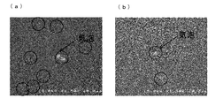
また、実施例1で得られたサンプルと、比較例1で得られたサンプルの断面を、同様に走査型電子顕微鏡を用いた観察した。得られた結果を図2((a)比較例1、(b)実施例1)にそれぞれ示した。
以上より、実施例1は比較例1と比べて、可視光線透過率が向上したものとなった。また、ナノフィラー粉末の含有量が多い比較例2は可視光線透過率が低下してしまった為、ナノフィラー粉末が多いとナノフィラー粉末を加えなかった比較例1と比較しても、可視光線透過率を大きく損なうことがわかった。さらに、実施例1より弱い力を加えながら混合した比較例3は、可視光線透過率は損なわなかったものの、泡を抑制する効果の程は小さいものとなった。また、図2より、比較例1と比較すると、実施例1では気泡が大幅に減少することが示された。
また、実施例2~6はいずれも比較例1~3と比較して、可視光線透過率の高いものとなることがわかった。また、先端周速度が他の実施例より遅い実施例5は、他の実施例より可視光線透過率の低いものとなった。これは、先端周速度が遅い方が混合物に加えられる遠心力は弱く、ナノフィラー粉末の凝集物を解す力が小さくなるためだと考えられる。
また、図1より、実施例1はガラス粉末表面にナノフィラー粉末が付着していることが明らかとなった。また、実施例2についてもガラス粉末表面にナノフィラー粉末が付着していることがわかった。また、いずれの実施例においても、ナノフィラー粉末の凝集物が混合前より解れていることがわかった。
実施例7
まず、ガラス粉末とナノフィラー粉末を、ガラス粉末:ナノフィラー粉末=98wt%:2wt%となるように1次混合し、混合物Aを得た。この時、混合方法としては多目的混合装置(日本コークス製)を用いて、回転羽根を先端周速度65m/sで回転させて遠心力を加えながら、10分間混合して混合物Aを得た。
まず、ガラス粉末とナノフィラー粉末を、ガラス粉末:ナノフィラー粉末=98wt%:2wt%となるように1次混合し、混合物Aを得た。この時、混合方法としては多目的混合装置(日本コークス製)を用いて、回転羽根を先端周速度65m/sで回転させて遠心力を加えながら、10分間混合して混合物Aを得た。
次に、混合物Aにα-SiAlON蛍光体粉末(平均粒子径15μm)を混合物A:蛍光体粉末=80:20(体積比)で、及び有機ビヒクル(有機バインダー:アクリル酸エステル、有機溶媒:α-テルピネオール及びトルエン)を固形分が10wt%になるように、それぞれ2次混合し、混合物Bとしてガラスペーストを得た。この時、混合方法としては、公転自転攪拌脱泡装置及びセラミック3本ロールミルを用いて約20分間混合及び混練を行った。なお、上記のセラミック3本ロールミルはガラスペーストを混練する装置であり、混合物に強い力を加えるものではない。
次に、ガラスペーストをバーコーターを用いてポリエチレンテレフタレート(PET)フィルム上に塗布し、乾燥させることにより厚み0.2~0.5mmのグリーンシートを得た。
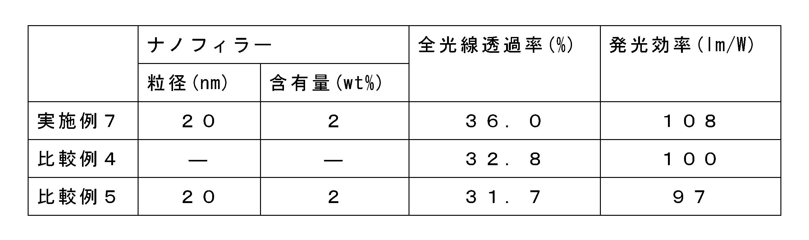
得られたグリーンシートを離型剤を塗布した無機基板に載せて、大気中で30分間、630℃で加熱することによって焼成し、焼成後に表面を研磨してフィルムを除去しサンプルを得た。得られたサンプルを直径20mm、厚み0.20mmまで研磨した後、分光光度計(U4000、HITACHI社製)を用いて、JIS K7105に準拠する方法で全光線透過率を測定した。結果を表2に示す。
(発光効率測定)
まず、励起光である青色LEDの光(発光ピーク波長445nm)を校正した積分球内に入射させ、光ファイバーを通じて小型分光器(オーシャンオプティクス製 HR-4000)に取り込み、発光スペクトル(エネルギー分布曲線)を得た。得られたスペクトルから、入力した青色LEDのエネルギー出力を計算した。
まず、励起光である青色LEDの光(発光ピーク波長445nm)を校正した積分球内に入射させ、光ファイバーを通じて小型分光器(オーシャンオプティクス製 HR-4000)に取り込み、発光スペクトル(エネルギー分布曲線)を得た。得られたスペクトルから、入力した青色LEDのエネルギー出力を計算した。
次に、励起光を測定サンプルの片面に入射させ、該測定サンプルの反対側の面から射出した光を校正した積分球内に入射させ、光ファイバーを通じて小型分光器に取り込み、発光スペクトを得た。得られたスペクトルに標準比視感度を掛け合わせて全光束を計算し、得られた全光束を前述した青色LEDのエネルギー出力で除して発光効率(lm/W)を算出した。得られた結果を表2に示した。
比較例4
ナノフィラー粉末を使用せず、一次混合を行わなかった他は、実施例7と同様の方法でグリーンシートを得た。次に、得られたグリーンシートを大気中で30分間、630℃で加熱した他は、実施例7と同様の方法でサンプルを得た。
ナノフィラー粉末を使用せず、一次混合を行わなかった他は、実施例7と同様の方法でグリーンシートを得た。次に、得られたグリーンシートを大気中で30分間、630℃で加熱した他は、実施例7と同様の方法でサンプルを得た。
比較例5
まず、ナノフィラー粉末、α-SiAlON蛍光体粉末、有機ビヒクルを約20分間1次混練し、その後ガラス粉末を加えて約20分間2次混錬し、ガラスペーストを得た。この時、1次混練、2次混合ともに、ナノフィラー粉末間にせん断力を加えないように、セラミック3本ロールミルを用いて混練及び混合を行った。得られたガラスペーストを用いて実施例7と同様の方法でグリーンシートを得た。次に、得られたグリーンシートを大気中で5時間、630℃で加熱した他は、実施例7と同様の方法でサンプルを得た。
まず、ナノフィラー粉末、α-SiAlON蛍光体粉末、有機ビヒクルを約20分間1次混練し、その後ガラス粉末を加えて約20分間2次混錬し、ガラスペーストを得た。この時、1次混練、2次混合ともに、ナノフィラー粉末間にせん断力を加えないように、セラミック3本ロールミルを用いて混練及び混合を行った。得られたガラスペーストを用いて実施例7と同様の方法でグリーンシートを得た。次に、得られたグリーンシートを大気中で5時間、630℃で加熱した他は、実施例7と同様の方法でサンプルを得た。
以上より、実施例7は比較例4,5よりも高い発光効率を示した。また、ナノフィラー粉末とガラス粉末を1次混合しなかった比較例5は、発光効率も全光線透過率も実施例7と比べて低いものとなった。
Claims (6)
- ガラス粉末を焼成して得るガラス部材の製造方法において、
一次粒子径が50nm以下の凝集したフィラー粉末と、該フィラー粉末の一次粒子径より平均粒子径D50が大きいガラス粉末と、を乾式混合し混合物を得る混合工程、及び
該混合物を焼成する焼成工程を有し、
該フィラー粉末は、該ガラス粉末と該フィラー粉末の合計量に対して0.01~10wt%含有されるものであり、
該混合工程は、1N/cm2以上の力を加えながら混合を行うものであることを特徴とするガラス部材の製造方法。 - 前記混合工程が、乳鉢を用いて前記混合物を押圧しながら混合するものであることを特徴とする請求項1に記載のガラス部材の製造方法。
- ガラス粉末を焼成して得るガラス部材の製造方法において、
一次粒子径が50nm以下の凝集したフィラー粉末と、該フィラー粉末の一次粒子径より平均粒子径D50が大きいガラス粉末と、を乾式混合し混合物を得る混合工程、及び
該混合物を焼成する焼成工程を有し、
該フィラー粉末は、該ガラス粉末と該フィラー粉末の合計量に対して0.01~10wt%含有されるものであり、
該混合工程は、混合機を用いて前記混合物を混合するものであり、該混合機が、回転羽根、回転ロータ、材料を装置壁面に衝突させる装置、又は超音波発生装置を搭載した混合機であることを特徴とするガラス部材の製造方法。 - 前記ガラス粉末の平均粒子径D50が、1~30μmの範囲内であることを特徴とする請求項1乃至請求項3のいずれかに記載のガラス部材の製造方法。
- 前記混合工程が、前記フィラー粉末と前記ガラス粉とを乾式混合して混合物Aを得る1次混合工程、及び
該混合物Aと、ガラス粉末、蛍光体粉末、無機フィラー、及び有機ビヒクルからなる群から選ばれる少なくとも1つとを混合して混合物Bを得る2次混合工程、を有し、
該第1次混合工程が、1N/cm2以上の力を加えながら混合を行う、又は回転羽根、回転ロータ、材料を装置壁面に衝突させる装置、若しくは超音波発生装置を搭載した混合機を用いて混合を行うものであることを特徴とする請求項1乃至請求項4のいずれかに記載のガラス部材の製造方法。 - 前記2次混合工程が、少なくとも有機ビヒクルを混合するものであり、湿式混合を行うものであることを特徴とする請求項5に記載のガラス部材の製造方法。
Applications Claiming Priority (2)
| Application Number | Priority Date | Filing Date | Title |
|---|---|---|---|
| JP2016-139893 | 2016-07-15 | ||
| JP2016139893A JP6748352B2 (ja) | 2016-07-15 | 2016-07-15 | ガラス部材の製造方法 |
Publications (1)
| Publication Number | Publication Date |
|---|---|
| WO2018012202A1 true WO2018012202A1 (ja) | 2018-01-18 |
Family
ID=60951744
Family Applications (1)
| Application Number | Title | Priority Date | Filing Date |
|---|---|---|---|
| PCT/JP2017/022436 Ceased WO2018012202A1 (ja) | 2016-07-15 | 2017-06-19 | ガラス部材の製造方法 |
Country Status (2)
| Country | Link |
|---|---|
| JP (1) | JP6748352B2 (ja) |
| WO (1) | WO2018012202A1 (ja) |
Citations (6)
| Publication number | Priority date | Publication date | Assignee | Title |
|---|---|---|---|---|
| JP2003115218A (ja) * | 2001-07-31 | 2003-04-18 | Ngk Spark Plug Co Ltd | 誘電体磁器 |
| JP2003327434A (ja) * | 2002-05-13 | 2003-11-19 | Nippon Electric Glass Co Ltd | 封着材料の製造方法 |
| JP2007182343A (ja) * | 2006-01-06 | 2007-07-19 | Toray Ind Inc | 感光性ペースト組成物およびそれを用いたフラットパネルディスプレイ部材 |
| JP2008039872A (ja) * | 2006-08-02 | 2008-02-21 | Toray Ind Inc | 焼成用感光性組成物及びそれを用いたディスプレイ部材 |
| JP2008247658A (ja) * | 2007-03-30 | 2008-10-16 | Hitachi Powdered Metals Co Ltd | ガラスペースト組成物 |
| JP2015046579A (ja) * | 2013-07-29 | 2015-03-12 | 旭硝子株式会社 | 光変換部材の製造方法、光変換部材、照明光源および液晶表示装置 |
-
2016
- 2016-07-15 JP JP2016139893A patent/JP6748352B2/ja not_active Expired - Fee Related
-
2017
- 2017-06-19 WO PCT/JP2017/022436 patent/WO2018012202A1/ja not_active Ceased
Patent Citations (6)
| Publication number | Priority date | Publication date | Assignee | Title |
|---|---|---|---|---|
| JP2003115218A (ja) * | 2001-07-31 | 2003-04-18 | Ngk Spark Plug Co Ltd | 誘電体磁器 |
| JP2003327434A (ja) * | 2002-05-13 | 2003-11-19 | Nippon Electric Glass Co Ltd | 封着材料の製造方法 |
| JP2007182343A (ja) * | 2006-01-06 | 2007-07-19 | Toray Ind Inc | 感光性ペースト組成物およびそれを用いたフラットパネルディスプレイ部材 |
| JP2008039872A (ja) * | 2006-08-02 | 2008-02-21 | Toray Ind Inc | 焼成用感光性組成物及びそれを用いたディスプレイ部材 |
| JP2008247658A (ja) * | 2007-03-30 | 2008-10-16 | Hitachi Powdered Metals Co Ltd | ガラスペースト組成物 |
| JP2015046579A (ja) * | 2013-07-29 | 2015-03-12 | 旭硝子株式会社 | 光変換部材の製造方法、光変換部材、照明光源および液晶表示装置 |
Also Published As
| Publication number | Publication date |
|---|---|
| JP6748352B2 (ja) | 2020-09-02 |
| JP2018008853A (ja) | 2018-01-18 |
Similar Documents
| Publication | Publication Date | Title |
|---|---|---|
| TWI625378B (zh) | 含有螢光體樹脂片與其製造方法、發光裝置與其製造方法以及螢光體分散樹脂組成物的製造方法 | |
| TWI654078B (zh) | 陶瓷磷光板及包括其之照明裝置 | |
| SG190320A1 (en) | Phosphor sheet, led and light emitting device using same and method for producing led | |
| CN111213075B (zh) | 波长变换部件和发光装置 | |
| KR101785798B1 (ko) | 형광체 분산 유리 | |
| JP2007191702A (ja) | 発光色変換材料 | |
| WO2018083903A1 (ja) | 波長変換部材、発光デバイス及び波長変換部材の製造方法 | |
| CN110785859B (zh) | 分散液、组合物、密封构件、发光装置、照明器具、显示装置及发光装置的制造方法 | |
| WO2018158194A1 (de) | Optoelektronisches bauelement und verfahren zur herstellung eines optoelektronischen bauelements | |
| JP2018035055A (ja) | 波長変換部材 | |
| CN1258489C (zh) | 低温可封接且不含铅的磷酸锡系玻璃及用其的复合材料 | |
| JP6748352B2 (ja) | ガラス部材の製造方法 | |
| JPWO2014162893A1 (ja) | 光変換部材、その製造方法、照明光源および液晶表示装置 | |
| JP2015046579A (ja) | 光変換部材の製造方法、光変換部材、照明光源および液晶表示装置 | |
| JP6934316B2 (ja) | 波長変換部材 | |
| JP5888690B2 (ja) | 白色セラミックカラー組成物 | |
| JP5358079B2 (ja) | 蓄光性セラミックスの成形材料組成物、この組成物を用いた蓄光性セラミックス成形体及びその製造方法 | |
| KR20230001983A (ko) | 파장 변환 부재 및 이를 포함하는 발광장치 | |
| KR102576253B1 (ko) | 파장 변환 부재 및 이를 포함하는 발광장치 | |
| WO2018008369A1 (ja) | 蛍光体封止用の封止材、及び波長変換部材 | |
| WO2014050684A1 (ja) | 蛍光体分散ガラスシート用ガラス組成物およびそれを用いた蛍光体分散ガラスシート | |
| WO2022107794A1 (ja) | 波長変換部材及びその製造方法 | |
| JP2025149274A (ja) | 混合蛍光体樹脂組成物の製造方法及び蛍光体シートの製造方法 | |
| WO2018037760A1 (ja) | 波長変換部材 | |
| JP2009206045A (ja) | 蛍光ランプ用塗料とそれを用いた塗膜および塗膜の製造方法並びに蛍光ランプ |
Legal Events
| Date | Code | Title | Description |
|---|---|---|---|
| 121 | Ep: the epo has been informed by wipo that ep was designated in this application |
Ref document number: 17827333 Country of ref document: EP Kind code of ref document: A1 |
|
| NENP | Non-entry into the national phase |
Ref country code: DE |
|
| 122 | Ep: pct application non-entry in european phase |
Ref document number: 17827333 Country of ref document: EP Kind code of ref document: A1 |