WO2018012128A1 - 紙葉類収納装置および紙葉類収納方法 - Google Patents
紙葉類収納装置および紙葉類収納方法 Download PDFInfo
- Publication number
- WO2018012128A1 WO2018012128A1 PCT/JP2017/019889 JP2017019889W WO2018012128A1 WO 2018012128 A1 WO2018012128 A1 WO 2018012128A1 JP 2017019889 W JP2017019889 W JP 2017019889W WO 2018012128 A1 WO2018012128 A1 WO 2018012128A1
- Authority
- WO
- WIPO (PCT)
- Prior art keywords
- unit
- storage bag
- banknote
- opening
- holding
- Prior art date
Links
Images


Classifications
-
- G—PHYSICS
- G07—CHECKING-DEVICES
- G07D—HANDLING OF COINS OR VALUABLE PAPERS, e.g. TESTING, SORTING BY DENOMINATIONS, COUNTING, DISPENSING, CHANGING OR DEPOSITING
- G07D11/00—Devices accepting coins; Devices accepting, dispensing, sorting or counting valuable papers
- G07D11/10—Mechanical details
- G07D11/12—Containers for valuable papers
-
- G—PHYSICS
- G07—CHECKING-DEVICES
- G07D—HANDLING OF COINS OR VALUABLE PAPERS, e.g. TESTING, SORTING BY DENOMINATIONS, COUNTING, DISPENSING, CHANGING OR DEPOSITING
- G07D11/00—Devices accepting coins; Devices accepting, dispensing, sorting or counting valuable papers
- G07D11/10—Mechanical details
- G07D11/16—Handling of valuable papers
-
- B—PERFORMING OPERATIONS; TRANSPORTING
- B65—CONVEYING; PACKING; STORING; HANDLING THIN OR FILAMENTARY MATERIAL
- B65H—HANDLING THIN OR FILAMENTARY MATERIAL, e.g. SHEETS, WEBS, CABLES
- B65H31/00—Pile receivers
- B65H31/26—Auxiliary devices for retaining articles in the pile
-
- E—FIXED CONSTRUCTIONS
- E05—LOCKS; KEYS; WINDOW OR DOOR FITTINGS; SAFES
- E05G—SAFES OR STRONG-ROOMS FOR VALUABLES; BANK PROTECTION DEVICES; SAFETY TRANSACTION PARTITIONS
- E05G1/00—Safes or strong-rooms for valuables
- E05G1/005—Portable strong boxes, e.g. which may be fixed to a wall or the like
-
- E—FIXED CONSTRUCTIONS
- E05—LOCKS; KEYS; WINDOW OR DOOR FITTINGS; SAFES
- E05G—SAFES OR STRONG-ROOMS FOR VALUABLES; BANK PROTECTION DEVICES; SAFETY TRANSACTION PARTITIONS
- E05G7/00—Safety transaction partitions, e.g. movable pay-plates; Bank drive-up windows
- E05G7/001—Bank depositories
-
- G—PHYSICS
- G07—CHECKING-DEVICES
- G07D—HANDLING OF COINS OR VALUABLE PAPERS, e.g. TESTING, SORTING BY DENOMINATIONS, COUNTING, DISPENSING, CHANGING OR DEPOSITING
- G07D11/00—Devices accepting coins; Devices accepting, dispensing, sorting or counting valuable papers
- G07D11/009—Depositing devices
-
- G—PHYSICS
- G07—CHECKING-DEVICES
- G07D—HANDLING OF COINS OR VALUABLE PAPERS, e.g. TESTING, SORTING BY DENOMINATIONS, COUNTING, DISPENSING, CHANGING OR DEPOSITING
- G07D11/00—Devices accepting coins; Devices accepting, dispensing, sorting or counting valuable papers
- G07D11/10—Mechanical details
- G07D11/12—Containers for valuable papers
- G07D11/125—Secure containers
-
- G—PHYSICS
- G07—CHECKING-DEVICES
- G07D—HANDLING OF COINS OR VALUABLE PAPERS, e.g. TESTING, SORTING BY DENOMINATIONS, COUNTING, DISPENSING, CHANGING OR DEPOSITING
- G07D11/00—Devices accepting coins; Devices accepting, dispensing, sorting or counting valuable papers
- G07D11/20—Controlling or monitoring the operation of devices; Data handling
- G07D11/30—Tracking or tracing valuable papers or cassettes
-
- G—PHYSICS
- G07—CHECKING-DEVICES
- G07D—HANDLING OF COINS OR VALUABLE PAPERS, e.g. TESTING, SORTING BY DENOMINATIONS, COUNTING, DISPENSING, CHANGING OR DEPOSITING
- G07D11/00—Devices accepting coins; Devices accepting, dispensing, sorting or counting valuable papers
- G07D11/20—Controlling or monitoring the operation of devices; Data handling
- G07D11/32—Record keeping
- G07D11/34—Monitoring the contents of devices, e.g. the number of stored valuable papers
-
- G—PHYSICS
- G07—CHECKING-DEVICES
- G07D—HANDLING OF COINS OR VALUABLE PAPERS, e.g. TESTING, SORTING BY DENOMINATIONS, COUNTING, DISPENSING, CHANGING OR DEPOSITING
- G07D13/00—Handling of coins or of valuable papers, characterised by a combination of mechanisms not covered by a single one of groups G07D1/00 - G07D11/00
-
- G—PHYSICS
- G07—CHECKING-DEVICES
- G07D—HANDLING OF COINS OR VALUABLE PAPERS, e.g. TESTING, SORTING BY DENOMINATIONS, COUNTING, DISPENSING, CHANGING OR DEPOSITING
- G07D9/00—Counting coins; Handling of coins not provided for in the other groups of this subclass
-
- G—PHYSICS
- G07—CHECKING-DEVICES
- G07F—COIN-FREED OR LIKE APPARATUS
- G07F19/00—Complete banking systems; Coded card-freed arrangements adapted for dispensing or receiving monies or the like and posting such transactions to existing accounts, e.g. automatic teller machines
- G07F19/20—Automatic teller machines [ATMs]
- G07F19/202—Depositing operations within ATMs
Definitions
- the present invention relates to a paper sheet storage device and a paper sheet storage method for storing paper sheets such as banknotes in a storage bag such as a pouch bag.
- a type that stores paper sheets taken into the machine body in a storage bag such as a pouch bag has been used.
- a paper sheet storage device one disclosed in, for example, Japanese Patent Application Laid-Open No. 2014-174581 of Japanese Patent Application Publication has been conventionally known.
- Japanese Patent Laid-Open No. 2014-174581 such a paper sheet storage device is used as a part of a cash accounting apparatus installed in a backyard area in a store such as a supermarket, for example.
- the cash accounting apparatus is designed to withdraw money as a change reserve for loading into a cash settlement apparatus provided in the front area, and to deposit money as sales collected from the cash settlement apparatus. ing.
- banknotes to be collected by a security company guard or the like are stored in a storage bag such as a pouch bag.
- a bill that is taken into the machine body by the take-in unit and identified by the identification unit is pouched. It is stored in a storage bag such as a bag. Further, when a storage company such as a pouch bag is collected by a security company security guard or the like, the opening of the storage bag is automatically sealed by a sealing portion. On the other hand, manual loading such as inserting paper sheets such as banknotes and checks directly into the storage bag held with the opening opened by the holding unit without passing through the take-in unit, transport unit, and identification unit
- the conventional cash settlement apparatus has a problem that it is not possible to add such paper sheets.
- the present invention has been made in consideration of such points, and when predetermined conditions are satisfied, addition of paper sheets to the storage bag held by the holding unit with the opening opened. It is an object of the present invention to provide a paper sheet storage device and a paper sheet storage method capable of loading and taking out paper sheets from the storage bag.
- the paper sheet storage device includes a holding unit that holds the storage bag in a state where the opening of the storage bag is open or a state in which the opening of the storage bag is sealed, and the storage that is held by the holding unit.
- a control unit that controls the restricting means so as to allow access to the storage bag held by the holding unit in a state.
- the paper sheet storage device of the present invention further includes a housing, and at least the holding portion, and a drawing portion that is pulled out from the inside of the housing, and the restricting means includes the drawing portion.
- the control unit controls the lock unit to allow the drawer to be pulled out of the housing when a predetermined condition is satisfied. You may come to do.
- the paper sheet storage device of the present invention is provided with a housing, at least the holding portion, a drawer portion that is pulled out from the inside of the housing, and provided in the housing, and the drawer portion is the A door that is opened when the housing is pulled out from the inside of the housing, and the restricting means includes a door lock portion that locks the door in a closed state, and the control portion is when a predetermined condition is satisfied
- the door lock portion may be controlled so as to release the lock that closes the door.
- the regulating means includes an opening / closing part that opens and closes a communication path between the opening part of the storage bag held by the holding part and the outside of the housing,
- the control unit controls the opening / closing unit to open a communication path between the opening of the storage bag held by the holding unit and the outside of the housing when a predetermined condition is satisfied. It may be.
- the paper sheet storage device of the present invention includes a take-in unit that takes a paper sheet into the housing, a transport unit that transports the paper sheet taken into the housing by the take-in unit, An identification unit that identifies a paper sheet conveyed by the conveyance unit, and the control unit passes through the capture unit, the conveyance unit, and the identification unit when a predetermined condition is satisfied.
- the restricting means may be controlled to allow paper sheets to be put into the storage bag held by the holding unit.
- control unit has a predetermined condition when a command to put paper sheets into the storage bag held by the holding unit without passing through the take-in unit, the transport unit, and the identification unit is input. It may be determined that is satisfied.
- an instruction unit for giving an instruction to put a paper sheet into a storage bag held by the holding unit without passing through the take-in unit, the transport unit, and the identification unit.
- a command to put paper sheets into the storage bag held by the holding unit without passing through the take-in unit, the transport unit, and the identification unit is input to the control unit It may be like this.
- the paper sheet storage device of the present invention inputs information on paper sheets that are put in a storage bag held by the holding unit without passing through the take-in unit, the transport unit, and the identification unit. May be further provided.
- control unit information on paper sheets put in a storage bag held by the holding unit without passing through the taking-in unit, the conveying unit, and the identifying unit is stored in the taking-in unit, the conveying unit, It may be managed separately from the paper sheets put in the storage bag held by the holding part via the part and the identification part.
- the paper sheet storage apparatus of the present invention further includes an authentication unit that authenticates the authority of the operator, and the control unit has a predetermined condition when the authority of the operator authenticated by the authentication unit is a predetermined authority. It may be determined that is satisfied.
- a plurality of the holding units are provided, and predetermined conditions are set corresponding to each of the storage bags held by the holding units, and the control unit For each of the storage bags held by each of the holding parts, the storage held by the holding part in an open state when a predetermined condition corresponding to the storage bag is satisfied.
- the restricting means may be controlled to allow access to the bag.
- the sealing unit when the access to the storage bag held by the holding unit is permitted in a state where the opening is open, the sealing unit is attached to the storage bag. You may make it seal the opening part of a storage bag in the aspect different from the case where access is not accept
- the sheet storage method of the present invention includes a holding unit that holds a storage bag in a state where the opening of the storage bag is open or a state in which the opening of the storage bag is sealed, and the storage that is held by the holding unit
- the paper sheet storage device includes a take-in unit that takes paper sheets into the housing, and a paper sheet taken into the housing by the take-in unit.
- a paper transport unit that further includes a transport unit that transports the paper sheet transported by the transport unit, and the paper sheet is stored in the storage bag that is held by the holding unit with the opening opened.
- the money handling machine includes a mounting portion on which a storage bag for storing money is mounted, a sealing portion for sealing an opening of the storage bag mounted on the mounting portion, and a mounting portion mounted on the mounting portion.
- An identification unit for identifying the money to be stored in the storage bag, and a setting unit for selecting and setting a sealing method for the opening of the storage bag from a plurality of sealing methods based on the identification result by the identification unit;
- a control unit that controls the sealing unit to seal the opening of the storage bag mounted on the mounting unit based on the sealing method set by the setting unit.
- the sealing portion includes a sealing member that seals the opening of the storage bag attached to the attachment portion
- the setting portion includes an opening of the storage bag.
- the sealing member seals the opening of the storage bag mounted on the mounting portion by heat, and the storage bags to be mounted on the mounting portion have different colors.
- a plurality of heat-sensitive light emitting layers are provided, and the setting unit sets an identification result by the identification unit when setting a location sealed by the sealing member in a storage bag attached to the attachment unit.
- the thermoluminescent layer sealed by the sealing member is selected and set, and the control unit is configured by the setting unit.
- the sealing member of the sealing part may be controlled so as to seal the set thermosensitive light emitting layer.
- a printing member that performs printing on the storage bag mounted on the mounting unit
- the setting unit prints on the storage bag by the printing member as a method for sealing the opening of the storage bag.
- the content is set based on the identification result by the identification unit, and the control unit prints on the storage bag mounted on the mounting unit based on the printing content set by the setting unit.
- the printing member may be controlled to perform.
- the printing member may perform printing on a portion sealed by the sealing portion in the storage bag attached to the mounting portion.
- a marking member for marking the storage bag mounted on the mounting portion is provided, and the setting portion is a stamp printed on the storage bag by the marking member as a sealing method of the opening of the storage bag.
- the content is set based on the identification result by the identification unit, and the control unit stamps the storage bag mounted on the mounting unit based on the marking content set by the setting unit.
- the marking member may be controlled to perform.
- the marking member may be configured to perform marking on a portion sealed by the sealing portion in the storage bag mounted on the mounting portion.
- a cutting member for partially cutting the storage bag mounted on the mounting portion is provided, and the setting unit stores the storage bag mounted on the mounting portion as a sealing method of the opening of the storage bag.
- the place in the bag that is cut by the cutting member is set based on the identification result by the identification unit, and the control unit is set by the setting unit in the storage bag mounted on the mounting unit.
- the cutting member may be controlled so as to cut the remaining place.
- the setting unit may determine the opening of the storage bag when the number or amount of money stored in the storage bag attached to the attachment unit is not determined based on the identification result by the identification unit.
- the sealing method may be different from the case where the number or amount of money stored in the storage bag mounted on the mounting portion is fixed.
- the setting unit includes a plurality of methods for sealing the opening of the storage bag corresponding to the number or amount of money stored in the storage bag mounted on the mounting unit based on the identification result by the identification unit. It may be set by selecting from a sealing method.
- the setting unit is configured based on a predetermined number or a predetermined amount of money that is stored in a storage bag mounted on the mounting unit based on an identification result by the identification unit. If the number of money stored in the storage bag attached to the mounting part is less than a predetermined number or a predetermined amount, It may be different from a certain case.
- the setting unit includes a plurality of sealing methods for sealing the opening of the storage bag corresponding to the denomination of money stored in the storage bag mounted on the mounting unit based on the identification result by the identification unit. It may be configured to select and set from a stopping method.
- the setting unit seals the opening of the storage bag when a plurality of denominations of money is stored in the storage bag mounted on the mounting unit based on the identification result by the identification unit.
- the method may be different from the case where the denomination of money stored in the storage bag mounted on the mounting portion is one.
- the setting unit based on the identification result by the identification unit, may be configured to open an opening of the storage bag when at least one currency stored in the storage bag mounted on the mounting unit is not genuine money.
- the sealing method may be different from the case where all the moneys stored in the storage bag mounted on the mounting part are genuine moneys.
- the money handling machine includes a mounting portion on which a storage bag for storing money is mounted, a sealing portion for sealing an opening of the storage bag mounted on the mounting portion, and information relating to the processing of money.
- An input unit for inputting, a setting unit for selecting and setting a sealing method of the opening of the storage bag from a plurality of sealing methods based on the information input to the input unit, and the setting unit
- a control unit that controls the sealing unit to seal the opening of the storage bag mounted on the mounting unit based on the sealing method.
- the information related to the processing of money input by the input unit includes the processing date and time of money, the date and time when the opening of the storage bag is sealed by the sealing unit, and the person in charge of processing money It may be at least one of a plurality of pieces of information including a place where the money handling machine is installed and information on a next process of the money handling machine.
- the money handling method of the present invention includes a step of mounting a storage bag for storing money on a mounting portion, a step of identifying money to be stored in a storage bag mounted on the mounting portion by an identification portion, and the identification A step of selecting and setting the sealing method of the opening of the storage bag from a plurality of sealing methods based on the identification result by the unit, and the storage mounted on the mounting unit based on the set sealing method And a step of sealing the opening of the bag.
- the money processing method of the present invention is based on a step of mounting a storage bag for storing money on the mounting portion, a step of inputting information related to processing of money by an input portion, and information input to the input portion, A step of selecting and setting a sealing method of the opening of the storage bag from a plurality of sealing methods, and a step of sealing the opening of the storage bag mounted on the mounting portion based on the set sealing method And.
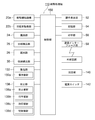
- FIG. 1 It is a schematic block diagram which shows an example of a structure of the banknote processing machine by the 1st Embodiment of this invention. It is a side view which shows the detail of a structure of the banknote accommodation mechanism in the banknote processing machine shown in FIG. It is a perspective view which shows the structure of a pair of holding member etc. in the banknote accommodation mechanism shown in FIG. It is a perspective view which shows the structure of the banknote storage bag which should be hold
- FIG. It is a functional block diagram which shows the structure of the control system of the banknote processing machine shown in FIG. It is a schematic block diagram which shows roughly the internal structure of the banknote processing machine by the 2nd Embodiment of this invention. It is a functional block diagram which shows the structure of the control system of the banknote processing machine shown in FIG. It is a side view which shows an example of the operation
- FIG. 1 It is a perspective view which shows the external appearance of the banknote deposit machine by the 3rd Embodiment of this invention. It is a side view which shows the internal structure of the banknote deposit machine shown in FIG. It is a functional block diagram which shows the structure of the control system of the banknote deposit machine shown in FIG.
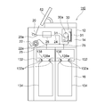
- FIG. 1 to 7 are views showing a banknote handling machine 10 according to the first embodiment.
- the banknote handling machine 10 is generally disposed in the front area or backyard area of a store such as a supermarket, or in a bank lobby or bank, and the banknote handling machine 10 is a banknote depositing process. Various processes such as these can be performed.
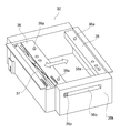
- the banknote processing machine 10 by this Embodiment has the housing
- the upper unit 14 and the lower unit 16 are accommodated inside the housing 12 so that they can be drawn forward from the front surface of the housing 12 (specifically, leftward in FIG. 1).
- a loading unit 20 such as a receiving hopper for loading bills into the inside from the outside of the housing 12 is provided on the front upper surface of the housing 12 (upper part of the left surface in FIG. 1). .
- a dispensing unit 22 for dispensing banknotes from the inside of the housing 12 to the outside is provided below the insertion unit 20 on the front surface (left surface in FIG. 1) of the housing 12. It has been.
- the billing unit 20 is provided with a bill feeding mechanism 20a for feeding bills placed on the loading unit 20 in a stacked state by the operator to the inside of the housing 12 one by one.
- a transport unit 24 that transports banknotes one by one in the housing 12 is provided inside the housing 12 of the banknote handling machine 10, and is inserted by a banknote feeding mechanism 20 a.
- the banknotes fed out from the bank are transported one by one by the transport unit 24.
- the identification part 26 is provided in the conveyance part 24, and the banknote advanced
- a dispensing unit 22 is connected to the conveyance unit 24, and banknotes sent from the conveyance unit 24 to the dispensing unit 22 are accumulated in the dispensing unit 22. .
- the dispensing unit 22 is accessible from the outside of the housing 12, and the operator can take out the banknotes accumulated in the dispensing unit 22 from the front surface of the housing 12.
- the impeller 22a is provided in the connection part with the discharge part 22 in the conveyance part 24, The said impeller 22a rotates in the counterclockwise direction in FIG. And when a banknote is sent to the dispensing part 22 from the conveyance part 24, the said impeller 22a rotates in the counterclockwise direction in FIG.
- the transport unit 24 is provided with a tape-type storage and feeding unit 30, and banknotes sent from the transport unit 24 to the storage and feeding unit 30 are stored in the storage and feeding unit 30.
- the banknotes stored in the storage and feeding unit 30 can be fed out to the transport unit 24 one by one.
- the storage and feeding section 30 is provided with a drum 30a that can rotate in both forward and reverse directions, and one end of a pair of strip-shaped tapes 31 is connected to the outer peripheral surface of the drum 30a.
- a banknote is sent from the conveyance part 24 to the storage and feeding part 30, the said banknote is wound up to the drum 30a with the tape 31 one sheet at a time by these strip
- the banknotes wound around the drums 30a are also discharged from the tapes 31 and fed out to the transport unit 24.
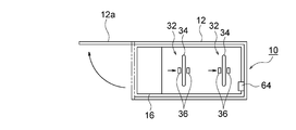
- the lower unit 16 includes a plurality of banknote storage mechanisms 32 for storing banknotes inside a banknote storage bag 34 such as a pouch bag provided with an opening on one side. (For example, two) are provided.
- Each bill storage mechanism 32 is provided with a pair of holding members 36 so as to be opposed to each other, and two opposing portions in the vicinity of the opening of the bill storage bag 34 are formed by each holding member 36.
- Each is to be held.
- a certain holding member 36 specifically, for example, the right holding member 36 in FIGS. 1 and 2
- another holding member 36 specifically, for example, The holding member 36 on the left side in FIGS. 1 and 2 can move toward the holding member 36 whose position is fixed.
- each holding member 36 is provided with a heating member 38. Then, after a predetermined amount of banknotes is stored in the banknote storage bag 34 held by each holding member 36 in the banknote storage mechanism 32, before the banknote storage bag 34 is taken out from the banknote storage mechanism 32, one holding member. In the state where 36 moves toward the other holding member 36 and these holding members 36 are joined to each other, heat is applied to a location in the vicinity of the opening of the banknote storage bag 34 by the heating member 38, thereby storing the banknote. The opening of the bag 34 is heat sealed (heat sealed).
- both holding members 36 are directed toward the other holding members 36, respectively.
- the holding member 36 may be joined to each other at the central position by moving to the central position.
- branch conveyance units 25 are branched from the conveyance unit 24 corresponding to each bill storage mechanism 32, and the conveyance unit 24 branches to the branch conveyance unit.
- the banknote branched into 25 is sent from the branch conveyance unit 25 to the banknote storage bag 34 attached to each banknote storage mechanism 32 and stored in the banknote storage bag 34.
- FIGS. 2 is a side view showing details of the configuration of the bill storage mechanism 32
- FIG. 3 is a perspective view showing the configuration of a pair of holding members 36 and the like in the bill storage mechanism 32 shown in FIG. 3
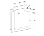
- a perspective view showing a configuration of a bill storage bag 34 such as a pouch bag held by each holding member 36 in the bill storage mechanism 32 shown in FIG.
- the bill storage mechanism 32 is configured to send a bill sent from the branch conveyance unit 25 of the upper unit 14 to the lower unit 16 to a bill storage bag 34 held by a pair of holding members 36.
- the banknote delivery part 48 consists of what combined a roller and a belt, and the banknote sent to the lower unit 16 from the branch conveyance part 25 of the upper unit 14 one sheet at a time on the temporary storage part 44 The data is sent and accumulated on the temporary holding unit 44.
- the temporary storage part 44 consists of a pair of right and left, and each temporary storage part 44 is below (namely, the arrow direction in FIG. 2) centering on the axis
- the stage 40 is composed of a pair of left and right stages, and each stage 40 is movable in the vertical direction and the horizontal direction in FIG.
- each stage 40 is driven by a stage drive unit 41 (see FIG. 7) such as an electric actuator.
- each stage 40 is provided with a heating member 42, respectively.
- one stage 40 for example, the left stage 40 in FIG. 2 becomes the other stage 40 (for example, the right stage 40 in FIG. 2).
- heat is applied to a location in the vicinity of the bottom of the bill storage bag 34 by the heating member 42, whereby the bottom of the bill storage bag 34 is heat sealed (heat sealed). ).
- both stages 40 move toward the other stage 40 to the center position. These stages 40 may be joined to each other at the central position.
- the left holding member 36 of the pair of left and right holding members 36 is provided with a pantograph 37, and the left holding member 36 moves toward the right holding member 36 by the pantograph 37.
- the holding members 36 are joined to each other by being moved. More specifically, a guide pin 36p is provided at the end of the left holding member 36, and a linear elongated hole in which the guide pin 36p is guided in the frame 36k that supports each holding member 36. 36q is provided.
- the long hole 36q is provided in the frame body 36k so as to extend in the horizontal direction.
- two pins 36a are provided on the upper surfaces of the pair of left and right holding members 36.
- two holes 34 b are provided at locations near the opening of the banknote storage bag 34 to be held by each holding member 36 (that is, at the upper end of the banknote storage bag 34).
- each holding member is provided in each hole 34b provided in each protrusion 34a of the banknote storage bag 34.
- the projections 34 a are held by the holding members 36 by passing the 36 pins 36 a.
- a push-in plate 46 is provided above the pair of temporary storage portions 44.
- the pushing plate 46 is provided with a pantograph 47 (see FIG. 7, not shown in FIG. 2).
- the pushing plate 46 is indicated by an arrow in FIG. 2 as the pantograph 47 expands and contracts in the vertical direction in FIG. The range can be moved up and down. As shown in FIG. 2, when such a pushing plate 46 moves downward, when the banknote temporarily held in each temporary storage section 44 is stored in the banknote storage bag 34, each temporary storage is performed. The banknotes held in the section 44 can be pushed toward the banknote storage bag 34.
- a one-sided lever 39 is provided below the left-side holding member 36 of the pair of holding members 36, and is held by the pair of holding members 36 by the one-sided lever 39.
- the banknotes stored in the banknote storage bag 34 are drawn to one side (specifically, the right side in FIG. 2) in the banknote storage bag 34. More specifically, the shift lever 39 is moved to the right from the state shown in FIG. 2 by a shift lever drive unit 39a (see FIG. 7) made of a pantograph, an electric actuator, or the like.
- the upper unit 14 and the lower unit 16 are each forward from the front of the said housing
- FIG. 1 to the left in FIG. 1.
- the operation when the lower unit 16 accommodated in the housing 12 is pulled forward from the front surface of the housing 12 will be described with reference to FIGS. 5 and 6.
- a door 12 a that is opened when the lower unit 16 is pulled out from the inside of the housing 12 is provided at the lower front portion of the housing 12.
- the banknote processing machine 10 of this Embodiment is provided with the door lock part 64 (refer FIG. 7) which locks the door 12a in a closed state.
- the door lock part 64 (refer FIG. 7) which locks the door 12a in a closed state.
- only a person having a predetermined authority can unlock the door 12a by the door lock portion 64 and open the door 12a.
- the operator When the banknote storage bag 34 in which banknotes are stored and the opening portion is heat-sealed (heat-sealed) by the heating member 38 is collected from the banknote processing machine 10, the operator first locks the door lock as shown in FIG. 5. 64, the door 12a is unlocked and the door 12a is opened. Next, as shown in FIG. 6, when the lower unit 16 is pulled forward from the front surface of the housing 12, the operator removes the bill storage bag 34 from each holding member 36 of the bill storage mechanism 32 and collects it from the lower unit 16. Will be able to.
- the banknote handling machine 10 of the present embodiment is provided with a lock portion 62 that restricts the lower unit 16 from being pulled out of the housing 12.
- the lock part 62 only needs to regulate the drawer of the lower unit 16 to the extent that the banknote storage bag 34 held by the holding member 36 cannot be accessed from the outside of the housing 12.
- the lock unit 62 may lock the lower unit 16 inside the housing 12 so that the lower unit 16 is held in a state of being housed inside the housing 12.
- the lower unit 16 accommodated in the housing 12 is removed from the housing 12 even when the door 12 a is opened. It cannot be pulled forward from the front.
- a restricting means 60 for selectively restricting access to the banknote storage bag 34 held by each holding member 36 by such a lock portion 62 and door lock portion 64. It is configured. Details of the function of such a restricting means 60 will be described later.
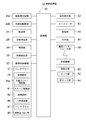
- the banknote handling machine 10 of the present embodiment is provided with a control unit 50 that controls each component of the banknote handling machine 10. More specifically, as shown in FIG. 7, the control unit 50 includes a bill feeding mechanism 20 a provided in the insertion unit 20 and an impeller driving unit for driving the impeller 22 a provided in the dispensing unit 22. 22b, transport unit 24, branch transport unit 25, identification unit 26, storage and feeding unit 30, bill storage mechanism 32 (specifically, pantograph 37, heating member 38, one-sided lever drive unit 39a, stage drive unit 41, heating The member 42, the temporary storage part 44, the pantograph 47, the banknote delivery part 48), etc. are connected, respectively. And while the signal which concerns on the identification result of the banknote by the identification part 26 is sent to the control part 50, the control part 50 controls operation
- an operation display unit 52, a card reader 53, a storage unit 54, a printing unit 56, and a communication interface unit 58 are connected to the control unit 50, respectively.
- the operation display unit 52 includes, for example, a touch panel provided on the upper surface of the housing 12, and is stored in each banknote storage bag 34, such as a banknote depositing process in the banknote processing machine 10. Information regarding the amount of banknotes being displayed is displayed on the operation display unit 52.
- the operator can give various commands to the control unit 50 by operating the operation display unit 52.
- the card reader 53 reads an ID card possessed by the operator, thereby authenticating the authority of the operator.
- the storage unit 54 is configured to store information related to processing history such as banknote depositing processing in the banknote processing machine 10, and the amount of banknotes stored in each banknote storage bag 34.
- the printing unit 56 prints information on processing history such as banknote depositing processing in the banknote handling machine 10 and information on banknotes stored in each banknote storage bag 34 on a receipt or the like.
- the control unit 50 can transmit and receive signals to and from an external device (specifically, for example, a host terminal) provided separately from the banknote handling machine 10 according to the present embodiment via the communication interface unit 58. It can be done. Specifically, the control unit 50 can transmit information stored in the storage unit 54 to an external device provided separately from the banknote processing machine 10 via the communication interface unit 58.
- a restricting means 60 is connected to the control unit 50.
- the restricting means 60 includes, for example, a lock portion 62 and a door lock portion 64, and selectively restricts access to the banknote storage bag 34 held by each holding member 36.
- the regulating means 60 is the lock portion 62
- the bill storage that is held by each holding member 36 by the lower unit 16 being locked inside the housing 12 by the lock portion 62.
- Access to the bag 34 is regulated.
- the restricting means 60 is the door lock portion 64, the door 12 a is locked in the closed state by the door lock portion 64, thereby accessing the banknote storage bag 34 held by each holding member 36. Will be regulated.
- the control unit 50 restricts access to the banknote storage bag 34 held by each holding member 36 in a state where the opening is opened when a predetermined condition is satisfied.
- the means 60 is controlled. More specifically, when a predetermined condition is satisfied, the control unit 50 puts a banknote into the banknote storage bag 34 held by each holding member 36 without passing through the insertion unit 20, the transport unit 24, and the identification unit 26.
- the restricting means 60 is controlled to allow direct entry. Specifically, in the case where the regulating means 60 is the lock portion 62, when the predetermined condition is satisfied, the locked state of the lower unit 16 inside the housing 12 by the lock portion 62 is released, and the lower unit 16 Can be pulled forward from the front surface of the housing 12.
- the restricting means 60 when the restricting means 60 is the door lock portion 64, when the predetermined condition is satisfied, the door 12a is unlocked by the door lock portion 64, and the door 12a can be opened.
- the restricting means 60 may include both the lock portion 62 and the door lock portion 64, or is configured by either one of the lock portion 62 and the door lock portion 64. It may be a thing. In the latter case, one of the lock unit 62 and the door lock unit 64 may be omitted, and only the other unit may be installed in the banknote handling machine 10 as the restricting unit 60.
- the operator can manually remove the reject banknotes accumulated in the dispensing unit 22 from the front surface of the housing 12 and re-insert it into the insertion unit 20.
- the banknote identified as a normal banknote by the identification unit 26 is sent to the storage / feeding unit 30 and temporarily stored in the storage / feeding unit 30.
- the number and total amount of the banknotes temporarily stored in the storage and feeding unit 30 are displayed on the operation display unit 52.
- banknotes are fed out one by one from the storage and feeding unit 30 to the transport unit 24 and branched from the bag transport unit 24 to the branch transport unit 25. It is sent from the branch conveyance unit 25 to the banknote storage bag 34 and stored in the banknote storage bag 34.
- the storage delivery part 30 is set. Alternatively, it may be used as a banknote storage unit until the full state or near-full state is resolved.
- the banknotes identified by the identification unit 26 are sent to the storage and feeding unit 30 and stored in the storage and feeding unit 30. Then, the banknote storage bag 34 that is in the full state or near-full state is taken out from the banknote storage mechanism 32 of the lower unit 16 by a security company security officer or the like, and the empty banknote storage bag 34 is attached to the banknote storage mechanism 32. Then, banknotes are fed out one by one from the storage and feeding unit 30 to the transport unit 24 and sent to the banknote storage bag 34 by the transport unit 24.
- the banknotes sent from the branch conveyance unit 25 of the upper unit 14 to the lower unit 16 are sent onto the pair of left and right temporary storage units 44 by the banknote delivery unit 48 and accumulated on these temporary storage units 44. Then, when a predetermined number of banknotes are accumulated on each temporary storage section 44, each temporary storage section 44 is respectively downward (that is, in the direction of the arrow in FIG. 2) about a shaft 44a provided at the base end portion.
- the bills accumulated on the temporary holding portions 44 fall from the temporary holding portions 44 by their own weight and are stored in the bill storage bag 34.
- each stage 40 is moved downward by the stage drive part 41, and next, the banknote storage bag 34 is sent from each temporary storage part 44.
- a bill storage space is formed inside the bill storage bag 34.
- the control unit 50 sends the banknote into the banknote storage bag 34 held by each holding member 36 and stores the banknote in the banknote storage bag 34.
- the pantograph 47 is controlled so that the banknote to be held is pushed into the inside of the bill storage bag 34 by the pushing plate 46.
- control unit 50 stores the banknotes in the banknote storage bags 34 held by the holding members 36 and moves the respective stages 40 downward, and then pushes the push plate 46 into the banknote storage bag 34.
- the pantograph 47 may be controlled so that the bottom of the banknote storage bag 34 is pressed toward each stage 40 through the banknotes accumulated in the banknote storage bag 34.
- the banknotes stacked in the stacked state inside the banknote storage bag 34 are compressed in the stacking direction by pushing the banknotes into the banknote storage bag 34 by the pushing plate 46, the banknote storage bag 34. It is possible to prevent the banknotes stored in a stacked state from being collapsed.
- the security guard When a security guard or the like of a security company collects the banknote storage bag 34 in which banknotes are stored from the banknote processing machine 10, the security guard first causes the card reader 53 to read the ID card he possesses. When the ID card of the guard is read by the card reader 53 and the authority of the guard is authenticated, the opening of the banknote storage bag 34 held by each holding member 36 in each banknote storage mechanism 32 is Heat sealing (heat sealing) is performed by the heating member 38.
- a banknote etc. are passed through the insertion part 20, the conveyance part 24, and the identification part 26 to the banknote storage bag 34 currently hold
- the banknote storage bag 34 is held by each holding member 36 of the banknote storage mechanism 32 in a state where the opening portion is opened, it is provided at the lower front portion of the housing 12 as shown in FIG. When the lower unit 16 is pulled forward from the front surface of the housing 12 as shown in FIG.
- banknote storage bag 34 paper money other than banknotes and banknotes (for example, processed by the upper unit 14) is stored in the banknote storage bag 34. Coupons, gift certificates, checks, foreign banknotes, etc.) that cannot be directly inserted or banknotes etc. can be taken out from the banknote storage bag 34.
- the control unit 50 determines that a predetermined condition is satisfied, the banknote storage bag 34 by the restricting means 60 including the lock unit 62 and the door lock unit 64.
- the access restriction to the banknote storage bag 34 held by each holding member 36 with the opening opened in the banknote storage mechanism 32 is permitted.
- various conditions are set in advance as the “predetermined conditions”. For example, the authority of the operator (specifically, information on the ID card of the operator read by the card reader 53), external information (Specifically, information transmitted from the external device to the control unit 50 via the communication interface unit 58), internal information (specifically, information input by the operator through the operation display unit 52), etc.
- the opening of the bill storage bag 34 held by each holding member 36 is automatically sealed by each heating member 38. Details of such operation will be described below.
- the operation display unit 52 may be held by each holding member 36 of the banknote storage mechanism 32 without passing through the upper unit 14 (specifically, the insertion unit 20, the conveyance unit 24, and the identification unit 26).
- An instruction that “paper sheets such as banknotes are directly inserted into the banknote storage bag 34” is given, or a signal related to such an instruction is transmitted from the external device to the control unit 50 via the communication interface unit 58.
- the command “input paper sheets such as banknotes directly into the banknote storage bag 34 held by each holding member 36 of the banknote storage mechanism 32 without passing through the upper unit 14” is input to the control unit 50.
- the control unit 50 determines that a predetermined condition is satisfied.
- an additional insertion button is displayed on the standby screen of the operation display unit 52, and when the additional insertion button is pressed by the operator, “banknote storage without passing through the upper unit 14”.
- An instruction “directly insert paper sheets such as banknotes into the banknote storage bag 34 held by each holding member 36 of the mechanism 32” is given.
- the restriction of access to the banknote storage bag 34 by the restriction means 60 including the lock part 62 and the door lock part 64 is released.
- the operator can open the door 12a and pull the lower unit 16 forward from the front surface of the housing 12. Therefore, the banknote storage mechanism 32 is held by each holding member 36 with the opening open.
- the bill storage bag 34 can be directly loaded with bills and paper sheets other than bills. Thereby, when the banknote storage mechanism 32 wants to additionally insert banknotes into the banknote storage bag 34 held by each holding member 36 with the opening being opened, or other than banknotes that cannot be processed by the upper unit 14.
- banknotes specifically, coupons, gift certificates, checks, foreign banknotes, etc.
- the input unit 20, the transport unit 24, and the identification unit 26 of the upper unit 14 are passed through. It becomes possible to insert paper sheets such as banknotes into the banknote storage bag 34 without the need.
- the command “inputting paper sheets such as banknotes directly into the banknote storage bag 34 held by each holding member 36 of the banknote storage mechanism 32 without passing through the upper unit 14” is not input to the control unit 50.
- access to the bill storage bag 34 is restricted by the restricting means 60, and the bill storage bag 34 is stored before the opening of the bill storage bag 34 held by each holding member 36 is sealed by each heating member 38. Paper sheets such as banknotes cannot be directly put into the bag 34.
- the control unit 50 can also manage information on paper sheets that are directly inserted into the banknote storage bag 34 without passing through the upper unit 14. Further, in this case, in the control unit 50, the information on the paper sheets that are directly inserted into the banknote storage bag 34 without passing through the insertion unit 20, the conveyance unit 24, and the identification unit 26 is obtained from the input unit 20, the conveyance unit 24, and the identification. The information is managed separately from the information on the banknotes that are put into the banknote storage bag 34 via the section 26.
- the operator when access to the bill storage bag 34 held by each holding member 36 is permitted in a state where the opening is opened by satisfying a predetermined condition, the operator operates A command for sealing the opening of the bill storage bag 34 can be input to the control unit 50 by the display unit 52. In this way, the operator does not go through the insertion unit 20, the conveyance unit 24, and the identification unit 26 of the upper unit 14 until a command for sealing the opening of the banknote storage bag 34 is input to the control unit 50 by the operator. Paper sheets such as banknotes can be directly put into the banknote storage bag 34.
- the card reader 53 causes the guard company's security guard to Even when the ID card is read and the authority of the guard is authenticated, the opening of the banknote storage bag 34 held by each holding member 36 is sealed by each heating member 38, and the banknote storage is performed.
- the bag 34 is in a recoverable state.
- the control unit 50 when the authority of the operator who is authenticated based on the ID card read by the card reader 53 is a predetermined authority (for example, a store manager or a store manager), the control unit 50 It may be determined that a predetermined condition is satisfied.
- a predetermined authority for example, a store manager or a store manager
- the authority of the operator is, for example, a store manager or a store manager
- such a manager or store manager opens the door 12a and pulls the lower unit 16 forward from the front surface of the housing 12.
- managers, store managers and the like can directly put banknotes and paper sheets other than banknotes into the banknote storage bag 34 held by each holding member 36 with the opening in the banknote storage mechanism 32 open. Or banknotes can be taken out from the banknote storage bag 34.
- the authority of the operator who is authenticated based on the ID card read by the card reader 53 is a general store clerk or the like, the predetermined condition is not satisfied.
- the banknote storage mechanism 32 the banknote storage bag 34 held by each holding member 36 with the opening being opened cannot be accessed. As a result, it is possible to prevent a banknote from being pulled out of the banknote storage bag 34 by a malicious clerk or the like.
- the operator may input a temporary password (one-time password) on the operation display unit 52.
- the control unit 50 determines that a predetermined condition is satisfied.
- the control is performed when the card reader 53 is used to read ID cards possessed by a plurality of operators and the authority of the plurality of operators is a predetermined authority combination set in advance.
- the unit 50 may determine that a predetermined condition is satisfied. Specifically, for example, the control unit 50 determines that a predetermined condition is satisfied only when an ID card possessed by a store manager or store manager and a security company security guard is read by the card reader 53, for example. It may be like this.
- each banknote storage mechanism 32 when access to the banknote storage bag 34 currently hold
- the banknote storage bag 34 A character or mark indicating that a paper sheet such as a banknote has been directly inserted may be formed in the vicinity of the sealed portion.
- a code such as a barcode or a two-dimensional code is printed in the vicinity of the opening of the bill storage bag 34 by a not-shown printing unit. It may be like this.
- information indicating that access to the bill storage bag 34 is permitted You may make it include in the information which concerns on the code printed on the banknote storage bag 34.
- the information on the paper sheets may be included in the information related to the code printed on the banknote storage bag 34.
- each banknote storage mechanism 32 when access to the banknote storage bag 34 held by each holding member 36 is permitted with the opening opened, the opening is sealed by each heating member 38.
- a warning message may be displayed on the operation display section 52 or a warning sound may be emitted.
- the banknote storage bag 34 is prevented from being taken away from the lower unit 16 by a malicious third party. Will be able to.
- two banknote storage mechanisms 32 are provided, and the banknote storage bags 34 are respectively held by the holding members 36 in each banknote storage mechanism 32.
- the authority on the store side is assigned to the banknote storage bag 34 corresponding to one banknote storage mechanism 32, and the authority on the police company side is assigned to the banknote storage bag 34 corresponding to both banknote storage mechanisms 32. Good.
- a predetermined condition is set corresponding to each of the two banknote storage bags 34 held by the holding members 36. More specifically, when the authority of the operator authenticated based on the ID card read by the card reader 53 is, for example, a store manager or a store manager, the banknote storage bag 34 to which the store authority is assigned.
- banknote handling machine 10 when paper sheets other than banknotes (for example, gift certificates, checks, coupons, etc.) are stored in the banknote storage bag 34, the store manager, store manager, etc. Thus, such a paper sheet can be taken out and visually confirmed.
- the authority of the operator authenticated based on the ID card read by the card reader 53 is, for example, a store manager or a store manager
- the banknote storage bag 34 to which the store authority is assigned is accessed.
- the opening of the banknote storage bag 34 to which the authority of the police company is assigned is automatically sealed by each heating member 38. This prevents store managers, store managers, and the like from taking out banknotes from the banknote storage bag 34 to which the authority of the police company is assigned.
- the authority of the operator who is authenticated based on the ID card read by the card reader 53 is, for example, a security guard of a security company
- the restriction of access by the restricting means 60 for all banknote storage bags 34 is released. Is done.
- a security guard at the security company inputs a command to access the bill storage bag 34 through the operation display unit 52
- the door 12a is opened and the lower unit 16 is pulled forward from the front surface of the housing 12, thereby It becomes possible to directly insert banknotes into the banknote storage bag 34 or take out banknotes from all banknote storage bags 34.
- the banknote storage bag 34 to which the authority on the store side is assigned in the lower unit 16 is provided on the front side, and the banknote storage bag 34 to which the authority on the police company side is assigned is provided on the back side.
- the authority of the operator authenticated based on the ID card read by the card reader 53 is, for example, a store manager or a store manager
- the banknote storage bag 34 to which the store authority is assigned When the operator inputs a command to access from the operation display unit 52, the lower unit 16 may be pulled out from the housing 12 by half.
- the banknote storage bag 34 on the front side is exposed to the outside of the housing 12, but the banknote storage bag 34 on the back side is exposed to the housing 12.
- the pull-out position of the lower unit 16 is regulated by the lock portion 62 so as to be housed in the interior of the housing.
- the operator can access the banknote storage bag 34 to which the authority on the store side is assigned. Cannot be accessed.
- the authority by the side of a police company is in the banknote storage bag 34 of the side with much storage amount of banknotes.
- the authority on the store side may be automatically assigned to the bill storage bag 34 on the side where the amount of bills stored is small.
- the authority of the operator who is authenticated based on the ID card read by the card reader 53 is, for example, a store manager or a store manager, only the banknote storage bag 34 on the side where the amount of banknotes stored is small.
- the access restriction by the restriction means 60 is released.
- a store manager, a store manager, or the like inputs a command to access the banknote storage bag 34 to which the store authority is assigned by the operation display unit 52, the door 12a is opened and the lower unit 16 is moved to the housing.
- the banknote storage bag 34 on the side where the amount of banknotes stored is small can be accessed.
- store managers, store managers, and the like can directly put paper sheets (for example, gift certificates, checks, coupons, etc.) other than banknotes into the banknote storage bag 34 on the side where the banknotes are stored less. become able to.
- the storage bag is held in the state where the opening of the banknote storage bag 34 is opened or the opening of the banknote storage bag 34 is sealed.
- Each holding member 36 as a holding portion to be held, each heating member 38 as a sealing portion for sealing the opening of the banknote storage bag 34 held by each holding member 36, and each holding member 36 holds the holding member 36.
- Each of the holding members 36 is held in a state where the opening is opened when a predetermined condition is satisfied.
- the restricting means 60 is controlled by the control unit 50 so as to allow access to the bill storage bag 34.
- each access member is allowed to access the banknote storage bag 34 held by each holding member 36 with the opening portion opened. It becomes possible to add paper sheets such as banknotes to the banknote storage bag 34 held by the holding member 36 and to take out banknotes from the banknote storage bag 34.
- each holding member 36 is provided, and the lower unit 16 is provided as a drawer
- the restricting means 60 includes a lock portion 62 that restricts the lower unit 16 from being pulled out of the housing 12.
- the lock unit 62 may be regulated so as to hold the entire lower unit 16 in a state of being housed in the housing 12.
- the lock unit 62 restricts the position of the lower unit 16 so that the banknote storage bag 34 held by the holding member 36 of the lower unit 16 cannot be accessed from the outside of the housing 12. You may do it.
- the lock unit 62 may be inside the housing 12 or may be outside the housing 12 to restrict the pulling operation of the lower unit 16 from the outside of the housing 12.
- the control unit 50 controls the lock unit 62 to allow the lower unit 16 to be pulled out of the housing 12 when a predetermined condition is satisfied. In this case, when a predetermined condition is satisfied, the operator pulls out the lower unit 16 from the inside of the housing 12 to the outside, so that the opening is opened by each holding member 36 provided in the lower unit 16. It becomes possible to access the banknote storage bag 34 held in the state where it is held.
- casing 12 to the exterior is provided.
- the regulating means 60 includes a door lock portion 64 that locks the door 12a in the closed state, and the control unit 50 performs a lock that closes the door 12a when a predetermined condition is satisfied.
- the door lock part 64 is controlled to be released. In this case, when a predetermined condition is satisfied, the operator opens the door 12a and pulls out the lower unit 16 from the inside of the housing 12 to the outside, thereby holding each holding member 36 provided in the lower unit 16. This makes it possible to access the bill storage bag 34 held with the opening opened.
- the door 12 a is not limited to the one provided on the front surface of the housing 12, and may be provided on the rear surface or side surface of the housing 12. Further, a plurality of holding members 36 may be provided, and a plurality of doors 12a may be provided so that each holding member 36 corresponds to a separate door 12a.
- the restricting means 60 may include both the lock part 62 and the door lock part 64, or the restricting means 60 from one of the lock part 62 and the door lock part 64. May be configured. In the latter case, one of the lock unit 62 and the door lock unit 64 may be omitted, and only the other unit may be installed in the banknote handling machine 10 as the restricting unit 60.
- the insertion part 20 as an intake part which takes in a banknote into the inside of the housing
- the control unit 50 when a predetermined condition is satisfied, The restricting means 60 is controlled so as to allow paper sheets such as banknotes to be put into the banknote storage bag 34 held by each holding member 36 without passing through the transport unit 24 and the identification unit 26.
- the control part 50 is banknote accommodation currently hold
- a command to put paper sheets such as banknotes into the bag 34 that is, a command to directly input paper sheets such as banknotes into the banknote storage bag 34
- the display unit 52 is provided with an additional insertion button, and when the additional insertion button is operated, the bill storage is held by each holding member 36 without passing through the insertion unit 20, the transport unit 24, and the identification unit 26.
- a command to insert paper sheets such as banknotes into the bag 34 may be input to the control unit 50.
- the banknote processing machine 10 of this Embodiment it puts into the banknote storage bag 34 currently hold
- Information on paper sheets such as banknotes can be input by the operation display unit 52.
- the operation display unit 52 is information on paper sheets such as banknotes that are put in the banknote storage bag 34 held by each holding member 36 without passing through the insertion unit 20, the conveyance unit 24, and the identification unit 26. It functions as an input unit for inputting.
- the control unit 50 can manage information on paper sheets such as banknotes directly inserted into the banknote storage bag 34.
- control unit 50 uses paper sheets such as banknotes to be put in the banknote storage bags 34 held by the holding members 36 without passing through the insertion unit 20, the conveyance unit 24, and the identification unit 26. (That is, information on paper sheets such as banknotes directly inserted into the banknote storage bag 34) is stored in the banknote storage bags held by the holding members 36 via the input unit 20, the transport unit 24, and the identification unit 26. 34 is managed separately from information on banknotes placed in the banknote 34 (that is, information on banknotes stored in the banknote storage bag 34 by the banknote depositing process described above).
- the card reader 53 is provided as an authentication part which authenticates an operator's authority as mentioned above, and the control part 50 is authenticated by the card reader 53. It may be determined that the predetermined condition is satisfied when the operator's authority is a predetermined authority.
- the authentication unit that authenticates the authority of the operator is not limited to the card reader 53.
- the operator may be authenticated when the operator inputs the operator's identification number and password to the operation display unit 52.
- the operation display unit 52 functions as an authentication unit that authenticates the authority of the operator.
- a plurality (specifically, two sets) of combinations of the pair of holding members 36 are provided and held by each holding member 36.
- the predetermined condition is set corresponding to each of the plurality (specifically, two) of banknote storage bags 34, and the control unit 50 holds the banknote storage bags held by the holding members 36 of each set.
- the control unit 50 holds the banknote storage bags held by the holding members 36 of each set.
- access to the banknote storage bag 34 held by each holding member 36 with the opening opened is permitted.
- the restricting means 60 is controlled to do so.
- each heating member 38 functioning as a sealing portion is transferred to the banknote storage bag 34 held by each holding member 36 in a state where the opening is open.
- the opening of the banknote storage bag 34 is sealed in a different manner from the case where access to the banknote storage bag 34 is not permitted.
- a security guard or the like of the security company collects the banknote storage bag 34 from the lower unit 16 of the banknote handling machine 10, paper sheets such as banknotes are additionally input into the banknote storage bag 34. It is possible to easily recognize that there is a possibility that a bill has been taken out from the bill storage bag 34.
- banknote processing machine 10 by this Embodiment and the processing method of the banknote by such a banknote processing machine 10 are not limited to the above aspects, A various change can be added.
- the restricting means 60 that selectively restricts access to the bill storage bag 34 held by each holding member 36 is in a closed state of the lock portion 62 and the door 12a that lock the lower unit 16 inside the housing 12. It is not limited to the door lock part 64 locked by. As long as the access to the banknote storage bag 34 held by each holding member 36 can be selectively restricted, a member other than the lock portion 62 and the door lock portion 64 described above is used as the restricting means 60. May be.
- the predetermined conditions for determining whether or not to allow access to the banknote storage bag 34 held by each holding member 36 in the state where the opening is opened are the insertion unit 20, the conveyance unit 24, and the identification.
- the authority of the operator is not limited to the predetermined authority. Even if a condition other than the above-mentioned conditions is used as a predetermined condition for determining whether or not to allow access to the banknote storage bag 34 held by each holding member 36 with the opening opened. Good.
- or FIG. 18 is a figure which shows the banknote processing machine 110 which concerns on 2nd Embodiment.
- the same components as those of the banknote handling machine 10 according to the first embodiment are denoted by the same reference numerals, and description thereof is omitted.
- the lower unit 16 has a plurality of mounting portions 132 (two in the example shown in FIG. 8) on which a banknote storage bag 134 such as a pouch bag can be mounted. ) Is provided. More specifically, in the lower unit 16, two mounting portions 132 are provided so as to be aligned along the direction in which the lower unit 16 is pulled out from the housing 12 (that is, the left direction in FIG. 8).
- Each mounting part 132 has a pair of holding members 132a provided so as to be opposed to each other, and two places facing each other in the vicinity of the opening of the banknote storage bag 134 are respectively held by the holding members 132a. It has become so. Here, the position of one holding member 132a is fixed, while the other holding member 132a can move toward the holding member 132a having a fixed position.
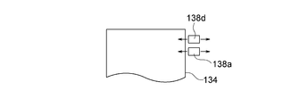
- each mounting portion 132 is provided with a sealing portion 138 that seals the opening of the bill storage bag 134 mounted on the mounting portion 132.
- the sealing part 138 has a sealing member 138 a that seals the opening of the banknote storage bag 134 attached to the attachment part 132.
- the sealing member 138a seals the opening of the bill storage bag 134 attached to the attachment part 132 by heat. More specifically, the sealing member 138a is provided in each holding member 132a, and after the banknote is stored in the banknote storage bag 134 attached to the mounting portion 132, one holding member 132a is the other holding member. In a state in which the holding members 132a are joined to each other while moving toward the 132a, heat is applied to locations near the opening of the bill storage bag 134 by the respective sealing members 138a, whereby the opening of the bill storage bag 134 is heated. It is designed to be sealed (heat sealed).
- each mounting portion 132 instead of one holding member 132a of the pair of holding members 132a moving toward the other holding member 132a, both holding members 132a are directed toward the other holding members 132a, respectively. These holding members 132a may be joined to each other by moving.
- the sealing unit 138 is used to print the printing member 138b that performs printing on the banknote storage bag 134 that is mounted on the mounting unit 132 or the stamp that performs printing on the banknote storage bag 134 that is mounted on the mounting unit 132.
- the member 138c may be included.
- the sealing part 138 may have the cutting member 138d which cut
- the cutting member 138d is configured to make a hole at a location near the opening of the banknote storage bag 134 attached to the mounting portion 132 or to form a notch at the edge of the banknote storage bag 134.
- the printing member 138b, the marking member 138c, and the cutting member 138d are used as constituent members that form a part of the sealing portion 138, but the printing member 138b, the marking member 138c, and the cutting member 138d Of these, at least one member or all of the members may be a separate component from the sealing portion 138.
- a temporary storage unit for temporarily holding the banknote sent from the transport unit 24 and a temporary storage unit above the pair of holding members 132 a in each mounting unit 132.
- a push-in plate for pushing the bill temporarily held into the bill storage bag 134.
- the banknotes sent from the transport unit 24 to each mounting unit 132 are stacked in a temporary storage unit in a stacked state, and the banknotes stacked in the temporary storage unit are stacked in a banknote storage bag.
- the pushing plate moves downward, so that the bills accumulated in the temporary storage unit are pushed downward and sent into the bill storage bag 134.
- the push-in plate moves downward and enters the banknote storage bag 134, and the banknotes stored in the banknote storage bag 134 are moved by the push-in plate. It is pushed down and compressed.
- the operator pulls the lower unit 16 forward from the front surface of the housing 12 (that is, the left direction in FIG. 8) to remove the banknote storage bag 134 storing banknotes from the mounting portion 132 or to empty banknotes.
- the storage bag 134 can be attached to the attachment portion 132.
- a plurality (two in the example shown in FIG. 8) of the branch transport units 25 are branched from the transport unit 24 corresponding to each mounting unit 132.
- the banknotes branched into two are sent from the branch transport section 25 to the banknote storage bags 134 mounted on the mounting sections 132 and stored in the banknote storage bags 134.
- the banknote handling machine 110 is provided with a control unit 150 that controls each component of the banknote handling machine 110. More specifically, as shown in FIG. 9, the control unit 150 includes a bill feeding mechanism 20 a provided in the insertion unit 20, and an impeller driving unit for driving the impeller 22 a provided in the dispensing unit 22. 22b, the transport unit 24, the branch transport unit 25, the identification unit 26, the storage and feeding unit 30, the mounting unit 132, the sealing unit 138, and the like are connected to each other. And while the signal which concerns on the recognition result of the banknote by the identification part 26 is sent to the control part 150, the control part 150 controls operation
- an operation display unit 52 a storage unit 54, a printing unit 56, and a communication interface unit 58 are connected to the control unit 150, respectively.
- the operation display unit 52 includes, for example, a touch panel provided on the upper surface of the housing 12, and is stored in each banknote storage bag 134, such as a banknote depositing process in the banknote processing machine 110. Information regarding the amount of banknotes being displayed is displayed on the operation display unit 52. The operator can give various commands to the control unit 150 by operating the operation display unit 52.
- the storage unit 54 is configured to store information on processing history such as banknote deposit processing in the banknote processing machine 110 and information on banknotes stored in each banknote storage bag 134.
- the printing unit 56 prints information on processing history such as banknote depositing processing in the banknote processing machine 110 and information on banknotes stored in each banknote storage bag 134 on a receipt or the like.
- the control unit 150 can transmit and receive signals to and from an external device (specifically, for example, a host terminal) provided separately from the banknote handling machine 110 according to the present embodiment via the communication interface unit 58. It can be done. For example, when the banknote storage bag 134 is collected by a security company security officer or the like, the control unit 150 transmits information related to the banknote storage bag 134 to the police company through the communication interface unit 58.
- control unit 150 selects and sets the sealing method of the opening of the banknote storage bag 134 from a plurality of sealing methods based on the identification result by the identification unit 26. Is connected. Details of the function of the setting unit 140 will be described later.
- a power switch 142 is connected to the control unit 150.
- the power switch 142 is provided on the housing 12 of the banknote handling machine 110, and the banknote handling machine 110 is activated or deactivated when the operator turns on / off the power switch 142.
- the banknote handling machine 110 performs banknote deposit processing.
- the banknotes inserted into the insertion unit 20 are one by one by the banknote feeding mechanism 20a. 12 is fed out and transported one by one by the transport unit 24.
- the banknote conveyed by the conveyance part 24 recognizes the money type, authenticity, front and back, correctness, new and old, a conveyance state, etc. by the identification part 26.
- the operator can manually remove the reject banknotes accumulated in the dispensing unit 22 from the front surface of the housing 12 and re-insert it into the insertion unit 20.
- the banknote identified as a normal banknote by the identification unit 26 is branched from the transport unit 24 to the branch transport unit 25 and sent from the branch transport unit 25 to the banknote storage bag 134. It will be stored.
- the banknote storage bag 134 to which the banknote identified by the identification unit 26 is to be sent is in a full state or a near full state, and the banknote cannot be stored in the banknote storage bag 134, the banknote storage bag 134 is identified by the identification unit 26.
- the bills that have been sent are sent to the storing and feeding unit 30 and stored in the storing and feeding unit 30.
- the banknote storage bag 134 in a full state or near-full state is removed from the mounting portion 132 of the lower unit 16 by a security company guard or a store clerk, and the empty banknote storage bag 134 is attached to the mounting portion 132.
- the banknotes are fed one by one from the storage and feeding unit 30 to the transport unit 24 and sent to the banknote storage bag 134 by the transport unit 24.
- each sealing member 138a moves to a location near the opening of the bill storage bag 134.
- the opening of the banknote storage bag 134 is heat sealed (heat sealed).
- worn is identified by the identification part 26, and the setting part 140 is based on this identification part 26.
- the sealing method of the opening of the banknote storage bag 134 by the sealing part 138 is selected and set from a plurality of sealing methods.
- the control unit 150 controls the sealing unit 138 to seal the opening of the banknote storage bag 134 attached to the attachment unit 132 based on the sealing method set by the setting unit 140. ing.
- the storage unit 54 stores the correspondence between the identification result by the identification unit 26 and the sealing method
- the setting unit 140 reads the sealing method corresponding to the identification result by the identification unit 26 from the storage unit 54. It may be set. Further, the correspondence between the identification result by the identification unit 26 stored in the storage unit 54 and the sealing method may be changed by the input by the operation display unit 52. Details of such operation will be described below.
- the setting unit 140 determines the place sealed by the sealing member 138 a in the bill storage bag 134 attached to the attachment unit 132 based on the identification result by the identification unit 26. Select from multiple locations to set. Further, the control unit 150 controls the sealing member 138a of the sealing unit 138 so as to seal the place set by the setting unit 140 in the banknote storage bag 134 mounted on the mounting unit 132. . Such an operation will be described with reference to FIG. As shown in FIG. 10, the sealing member 138 a is movable in the up and down direction and the left and right direction in FIG. 10 with respect to the banknote storage bag 134 mounted in the mounting unit 132.
- the sealing member 138a of the sealing part 138 may seal the opening of the said banknote storage bag 134 in one place over the full width of the banknote storage bag 134 (namely, figure). 10 may be sealed with only one of the two sealed locations indicated by reference numeral 135), or the bill storage bag 134 at two locations across the entire width of the bill storage bag 134. May be sealed (that is, they may be sealed at two sealing locations indicated by reference numeral 135 in FIG. 10).
- the setting unit 140 seals the opening of the banknote storage bag 134 at one location over the entire width of the banknote storage bag 134 by the sealing member 138a of the sealing unit 138 based on the identification result by the identification unit 26. Alternatively, it is set whether the opening of the bill storage bag 134 is sealed at two places. More specifically, when the number or amount of banknotes stored in the banknote storage bag 134 mounted on the mounting unit 132 is determined based on the identification result by the identifying unit 26 (that is, mounted on the mounting unit 132).
- the setting unit 140 has the sealing member 138a of the sealing unit 138 at one location over the entire width of the banknote storage bag 134. Is set to seal the opening of the bill storage bag 134.
- the setting unit 140 is configured so that the sealing member 138a of the sealing unit 138 has two banknotes over the entire width of the banknote storage bag 134.
- the banknote storage bag 134 mounted on the mounting unit 132 has its full width. In one place, the opening is sealed by the sealing member 138a of the sealing portion 138, while the number or amount of banknotes stored in the banknote storage bag 134 mounted on the mounting portion 132 is If not confirmed, the banknote storage bag 134 attached to the attachment part 132 has its opening sealed by the sealing member 138a of the sealing part 138 at two locations over its entire width. Thus, the operator can easily recognize whether or not the number or amount of banknotes stored in the banknote storage bag 134 has been determined simply by looking at the appearance of the banknote storage bag 134. .
- banknotes whose denomination could not be specified based on the identification result by the identification unit 26 are forced to the banknote storage bag 134.
- the operator can set the forced deposit mode to be stored in the operation display unit 52.
- a forced deposit mode is set, when a banknote whose denomination could not be specified based on the identification result by the identification unit 26 is forcibly stored in the banknote storage bag 134, The number or amount of banknotes stored in the banknote storage bag 134 mounted on the mounting unit 132 is not determined.
- banknote depositing processing is performed in the banknote handling machine 110
- the banknote handling abnormality occurs in the transport unit 24 and processing by the banknote handling machine 110 is stopped
- the banknote handling machine 110 immediately before being stored in the banknote storage bag 134 is used.
- Whether the banknotes or banknotes stored in the banknote storage bags 134 are stored in the banknote storage bags 134 is uncertain. In such a case as well, the banknote storages mounted in the mounting unit 132 are stored. The number or amount of banknotes stored in the bag 134 is not determined.
- the sealing member 138a of the sealing unit 138 seals the opening of the banknote storage bag 134 at one place over the entire width of the banknote storage bag 134 mounted on the mounting unit 132, and the identification unit 26 Depending on the identification result, additional sealing may be performed at a location above the sealing location across the entire width of the bill storage bag 134.
- reference numerals 135, 135a, and 135b indicate locations where the bill storage bag 134 attached to the attachment portion 132 is sealed by the sealing member 138a of the sealing portion 138. Shown in hatched area.
- the setting unit 140 stores the banknote in the sealing member 138a of the sealing unit 138 as shown in FIG. It is set to perform sealing at a place indicated by a reference numeral 135 and a reference numeral 135a in the bag 134.
- the setting unit 140 seals the sealing member 138a of the sealing unit 138 at a location indicated by the reference symbol 135 and the reference symbol 135b in the banknote storage bag 134.
- the sealing member 138a of the sealing portion 138 is set to be sealed at a place indicated by a reference symbol 135, a reference symbol 135a, and a reference symbol 135b in the banknote storage bag 134. If the state of the banknote stored in the banknote storage bag 134 mounted on the mounting unit 132 does not apply to any of the above based on the identification result by the identification unit 26, the setting unit 140 It is set that the sealing member 138a of the portion 138 performs sealing only at the place indicated by the reference numeral 135 in FIG. Thus, the operator can easily recognize information related to the banknotes stored in the banknote storage bag 134 only by looking at the appearance of the banknote storage bag 134.
- the upper limit number or upper limit amount of banknotes stored in the banknote storage bag 134 is preset in the control unit 150 and stored in the banknote storage bag 134 mounted on the mounting unit 132.
- the setting unit 140 includes a sealing unit as shown in FIG.
- the sealing member 138a of 138 is set to perform sealing at a place indicated by a reference symbol 135 and a reference symbol 135b in the banknote storage bag 134.
- the setting unit 140 displays the setting shown in FIG.
- the sealing member 138a of the sealing portion 138 may be set to perform sealing at a location indicated by a reference symbol 135 and a reference symbol 135b in the banknote storage bag 134.
- worn contains a false banknote
- the issued banknote includes a banknote whose authenticity is uncertain (hereinafter also referred to as a true / false uncertain ticket), or includes a medium determined to be not a banknote (for example, a gift certificate or a check)
- banknotes stored in the banknote storage bag 134 mounted on the mounting unit 132 include banknotes other than genuine banknotes.
- the banknote stored in the banknote storage bag 134 mounted on the mounting unit 132 includes a banknote or an old ticket issued by a country or organization other than the home country
- the banknote mounted on the mounting unit 132 may be regarded as including banknotes other than genuine banknotes.
- the setting part 140 sets the place sealed by the sealing member 138a in the banknote storage bag 134 attached to the mounting part 132 as the identification result by the identification part 26 as a sealing method of the opening of the banknote storage bag 134.
- a plurality of thermosensitive light emitting layers having different colors are provided, and the setting portion 140 is connected to the banknote storage bag mounted on the mounting portion 132.
- the sealing member 138a among the plurality of thermosensitive light emitting layers provided in the banknote storage bag 134 is sealed based on the identification result by the identification unit 26.
- the thermosensitive light emitting layer to be stopped may be selected and set.
- thermoluminescent layer 134a that emits red light when heat-sealed by the sealing member 138a.
- the second thermoluminescent layer 134b that emits blue light and the third thermoluminescent layer 134c that emits yellow light when heat-sealed by the sealing member 138a are arranged along the width direction of the bill storage bag 134. Yes.
- the sealing member 138a is sealed among the three thermosensitive light emitting layers 134a to 134c based on the identification result by the identification unit 26.
- the heat-sensitive light emitting layer is selected and set.
- the color of the thermoluminescent layer provided near the opening of the banknote storage bag 134 becomes different, The operator can easily recognize information relating to the banknotes stored in the banknote storage bag 134 only by looking at the color emitted by the thermosensitive light emitting layer in the vicinity of the opening of the banknote storage bag 134.
- the setting unit 140 sets the opening of the banknote storage bag 134 to the banknote storage bag 134 by the printing member 138b.
- the printed content to be printed is set based on the identification result by the identifying unit 26, and the control unit 150 has the banknote mounted on the mounting unit 132 based on the printed content set by the setting unit 140.
- the printing member 138b of the sealing portion 138 may be controlled so as to print on the storage bag 134. Such an operation will be described with reference to FIG. In the present embodiment, a printer such as an ink jet printer is used as the printing member 138b. Further, as shown in FIG.
- the sealing member 138 a and the printing member 138 b are movable in the left-right direction in FIG. 13 with respect to the banknote storage bag 134 attached to the attachment part 132.
- the sealing member 138 a of the sealing part 138 seals the opening of the banknote storage bag 134 at one place over the entire width of the banknote storage bag 134 mounted on the mounting part 132.
- the printing member 138b prints various characters at a location above the location sealed by the sealing member 138a in the bill storage bag 134.
- the setting unit 140 It is set to print the characters “abnormality in money” on the bill storage bag 134 by the printing member 138b.
- the banknote for example, a fake ticket and a genuine uncertain ticket
- the setting unit 140 sets the printing of the characters “There is a genuine / uncertain ticket” on the banknote storage bag 134 by the printing member 138b.
- the printing member 138b prints various characters in a place above the portion sealed by the sealing member 138a in the banknote storage bag 134 attached to the attachment portion 132.
- Various characters may be printed at a location sealed by the sealing member 138a in the bill storage bag 134 attached to the attachment portion 132.
- the sealing member 138a and the printing member 138b may be integrated.
- the sealing part 138 has the sealing member 138a and the marking member 138c
- the setting part 140 is used as the sealing method of opening of the banknote storage bag 134 to the banknote storage bag 134 by the marking member 138c.
- the stamp content to be stamped is set based on the identification result by the identification unit 26, and the control unit 150 is based on the stamp content set by the setting unit 140 and the banknote mounted on the mounting unit 132.
- the marking member 138c of the sealing portion 138 may be controlled so as to mark the storage bag 134. Such an operation will be described with reference to FIG. As shown in FIG. 14, a plurality of (three in the example shown in FIG.
- marking members 138 c are provided along the height direction of the bill storage bag 134 attached to the attachment portion 132, and each marking member A sealing member 138a is provided on each of 138c. That is, three members in which the sealing member 138a and the marking member 138c are integrated are provided. Further, each marking member 138c is movable in the left-right direction in FIG. 14 with respect to the bill storage bag 134 attached to the attachment part 132.
- the sealing member 138 a of the sealing part 138 seals the opening of the banknote storage bag 134 at one place over the entire width of the banknote storage bag 134 mounted on the mounting part 132.
- each marking member 138c is configured to imprint various characters on the portion sealed by the sealing member 138a in the bill storage bag 134.
- the marking member 138c located on the uppermost side among the three marking members 138c is designed so as to mark the bill storage bag 134 with a letter “abnormal amount of money”, and from above among the three marking members 138c.
- the second marking member 138c is designed to stamp the bill storage bag 134 with a letter “true / false unrecognized ticket”, and the lowest marking member 138c among the three marking members 138c. Is imprinted with the letters “over storage amount” on the banknote storage bag 134.
- the setting unit 140 sets the uppermost side. It is set that the banknote storage bag 134 mounted on the mounting portion 132 is sealed and stamped by the sealing member 138a and the stamping member 138c. Moreover, based on the identification result by the identification part 26, the banknote (for example, a fake ticket and a genuine uncertain ticket) which is not a genuine banknote in the banknote accommodated in the banknote storage bag 134 with which the mounting part 132 was mounted
- worn is at least.
- the setting unit 140 seals and stamps the bill storage bag 134 mounted on the mounting unit 132 by the second sealing member 138a and the stamping member 138c from the top. Set that. Further, when the number or amount of banknotes stored in the banknote storage bag 134 mounted on the mounting unit 132 is greater than a predetermined number or a predetermined amount based on the identification result by the identification unit 26 The setting unit 140 sets that the banknote storage bag 134 attached to the attachment unit 132 is sealed and stamped by the lowermost sealing member 138a and the marking member 138c. Thus, the operator can easily recognize information relating to the banknotes stored in the banknote storage bag 134 only by looking at the characters stamped on the banknote storage bag 134.
- the sealing part 138 has the sealing member 138a and the cutting member 138d
- the setting part 140 is the banknote with which the mounting part 132 is mounted
- the location of the storage bag 134 to be cut by the cutting member 138d is set based on the identification result by the identification unit 26, and the control unit 150 sets the setting unit in the banknote storage bag 134 attached to the attachment unit 132.
- the cutting member 138d of the sealing portion 138 may be controlled so as to cut the place set by 140. Such an operation will be described with reference to FIGS. 15 and 16. In the example shown in FIGS.
- the cutting member 138 d is configured to open a hole in the vicinity of the opening of the banknote storage bag 134 attached to the attachment portion 132. Further, as shown in FIG. 15, the sealing member 138a and the cutting member 138d are movable in the left-right direction in FIGS. 15 and 16, respectively, with respect to the banknote storage bag 134 attached to the attachment part 132. Here, the sealing member 138 a of the sealing part 138 seals the opening of the banknote storage bag 134 at one place over the entire width of the banknote storage bag 134 mounted on the mounting part 132. In FIG.
- a hatched area indicated by a reference numeral 135 indicates a place where the banknote storage bag 134 attached to the attachment part 132 is sealed by the sealing member 138 a of the sealing part 138. Further, the cutting member 138d is configured to make a hole in the banknote storage bag 134 at a location above the location sealed by the sealing member 138a in the banknote storage bag 134. 16 (a) to 16 (c), reference numerals 139a and 139b indicate locations where holes are opened by the cutting member 138d in the bill storage bag 134 attached to the attachment portion 132. FIG.
- the setting unit 140 is configured such that the cutting member 138d of the sealing unit 138 is a banknote storage bag as shown in FIG. It is set that a hole is to be drilled at a location indicated by reference numeral 139a in 134. Further, when the number or amount of banknotes stored in the banknote storage bag 134 mounted on the mounting unit 132 is greater than a predetermined number or a predetermined amount based on the identification result by the identification unit 26 As shown in FIG.
- the setting unit 140 sets that the cutting member 138d of the sealing unit 138 opens a hole at the place indicated by the reference numeral 139b in the banknote storage bag 134. Moreover, based on the identification result by the identification part 26, when a false banknote is contained in the banknote accommodated in the banknote storage bag 134 with which the mounting part 132 was mounted
- the setting unit 140 It is set that a hole is not made in the bill storage bag 134 by the cutting member 138d of the portion 138. As a result, the operator can easily recognize information related to the banknotes stored in the banknote storage bag 134 only by looking at the hole formed in the vicinity of the opening of the banknote storage bag 134.
- the setting unit 140 determines the number or amount of banknotes stored in the banknote storage bag 134 mounted on the mounting unit 132 based on the identification result by the identification unit 26. If not, the method of sealing the opening of the banknote storage bag 134 is different from the case where the number or amount of banknotes stored in the banknote storage bag 134 mounted on the mounting unit 132 is determined. It is like that.
- the setting unit 140 also sets a predetermined number or a predetermined number of banknotes stored in the banknote storage bag 134 mounted on the mounting unit 132 based on the identification result by the identification unit 26.
- the method of sealing the opening of the bill storage bag 134 is used as a predetermined number of bills stored in the bill storage bag 134 attached to the attachment portion 132 or a predetermined number of amounts. Or, it is different from the case where the amount is not more than a predetermined amount.
- the setting part 140 is based on the identification result by the identification part 26, and at least 1 banknote accommodated in the banknote storage bag 134 with which the mounting part 132 was mounted
- worn is not a genuine banknote, a banknote storage bag
- the method of sealing the opening 134 is different from the case where all the banknotes stored in the banknote storage bag 134 mounted on the mounting portion 132 are genuine banknotes.
- the setting of the method for sealing the opening of the bill storage bag 134 by the setting unit 140 is not limited to the above-described aspect.
- the setting unit 140 seals the opening of the storage bag corresponding to the number or amount of banknotes stored in the banknote storage bag 134 mounted on the mounting unit 132 based on the identification result by the identification unit 26.
- the stopping method may be selected and set from a plurality of sealing methods. For example, information on the number or amount of banknotes stored in the banknote storage bag 134 mounted on the mounting unit 132 may be printed in the vicinity of the opening of the banknote storage bag 134 by the printing member 138b. .
- the setting unit 140 seals the opening of the banknote storage bag 134 corresponding to the denomination of the banknote stored in the banknote storage bag 134 mounted on the mounting unit 132 based on the identification result by the identification unit 26. May be selected and set from a plurality of sealing methods. In this case, when the banknote storage bag 134 attached to the attachment unit 132 stores a plurality of denominations of banknotes based on the identification result by the identification unit 26, the setting unit 140 stores the banknote storage bag 134. The method for sealing the opening may be different from the case where the denomination of the banknote stored in the banknote storage bag 134 mounted on the mounting unit 132 is one.
- the setting part 140 is limited to the aspect which selects and sets the sealing method of the opening of the banknote storage bag 134 from several sealing methods based on the identification result by the identification part 26. FIG. never happen.
- the setting unit 140 selects and sets the sealing method of the opening of the banknote storage bag 134 from a plurality of sealing methods based on the information input by the operation display unit 52, and the control unit 150
- the sealing unit 138 may be controlled so as to seal the opening of the banknote storage bag 134 mounted on the mounting unit 132 based on the sealing method set by the setting unit 140.
- the processing date and time of banknotes by the banknote processing machine 110 the date and time when the opening of the banknote storage bag 134 is sealed by the sealing unit 138, the person in charge of processing banknotes in the banknote processing machine 110, and the place where the banknote processing machine 110 is installed (For example, information on a store where the banknote handling machine 110 is installed) and information on the next process of the banknote handling machine 110 are input by the operator through the operation display unit 52, the sealing unit Information input by the operation display unit 52 may be printed at a location near the opening of the banknote storage bag 134 by the printing member 138b of 138.
- the information of the next process of the banknote processing machine 110 means the information which concerns on the next process by which the banknote storage bag 134 is processed.
- the banknote storage bag 134 taken out from the banknote processing machine 110 is transported to a sorting processing place, and the banknotes stored in the banknote storing bag 134 are processed by a sorting machine installed in the sorting processing place.
- the characters “sorter processing” are printed at a location near the opening of the bill storage bag 134 by the printing member 138 b of the sealing portion 138.
- the name of the banknote processing center is displayed at a location near the opening of the banknote storage bag 134 by the printing member 138b of the sealing unit 138. May be printed. Further, the name of the security company that transfers the bill storage bag 134 taken out from the bill processing machine 110 is printed at a location near the opening of the bill storage bag 134 by the printing member 138b of the sealing portion 138. May be.
- the opening of the banknote storage bag 134 attached to the attachment part 132 may be sealed by the sealing part 138 when a predetermined condition is satisfied. Specifically, when the power switch 142 is turned off by the operator, the number of banknotes stored in the banknote storage bag 134 mounted on the mounting unit 132 is greater than a predetermined number. In many cases, the opening of the bill storage bag 134 attached to the attachment part 132 is sealed by the sealing part 138.
- the bill storage bag 134 based on the amount of banknotes to be stored in the banknote storage bag 134 calculated based on the deposit amount of banknotes input by the operation display unit 52 and the identification result by the identification unit 26 is actually used.
- an opening of the banknote storage bag 134 mounted on the mounting unit 132 is sealed by the sealing unit 138, assuming that a miscalculation has occurred. It may be like this.
- the opening of the bill storage bag 134 attached to the attachment part 132 may be sealed by the sealing part 138.
- the banknote accommodated in the banknote storage bag 134 will be in an upright state, and the banknote stored in the banknote storage bag 134 should be sealed by the sealing member 138a of the sealing portion 138.
- the operation display unit is set when the schedule of the security company entrusted to transport the banknote storage bag 134 is set closest to the next business day
- the bill storage bag 134 is stored on the basis of information input by the control unit 52 or information transmitted from the external device to the control unit 150 via the communication interface unit 58.
- the opening of the banknote storage bag 134 that is mounted to the mounting portion 132 may be adapted to be sealed by the sealing unit 138.
- the predetermined condition is satisfied in addition to the case where the banknote storage bag 134 in the full state or the near full state is removed from the mounting portion 132 of the lower unit 16 by a security company guard or a store clerk.
- the banknote storage bag 134 attached to the mounting part 132 is sealed with the sealing part 138, the collection operation of the banknote storage bag 134 can be performed flexibly and smoothly. Become.
- the tape-type storage / feeding unit 30 may be used to store banknotes managed on the store side.
- banknotes of specific denominations such as high-value banknotes, banknotes issued by specific countries and organizations other than their own country, paper sheets other than banknotes such as coupons and checks, and specific banknotes such as fake banknotes It may be stored in the storage and feeding unit 30.
- recover, the banknote which should be used as change on the next day, etc. may be accommodated in the accommodation
- the specific banknotes stored in the storage and feeding unit 30 are fed out from the storage and feeding unit 30 to the transport unit 24 and mounted on the mounting unit 132 by the transport unit 24 when a predetermined condition is satisfied.
- the bill storage bag 134 may be sent.
- a banknote handled as sales in the next day conversion is stored in the storage and feeding unit 30 as a specific banknote
- the sales day of the banknote is reached, the sales in the next day conversion
- the banknotes to be handled may be fed from the storage and feeding unit 30 to the transport unit 24 and sent to the banknote storage bag 134 mounted on the mounting unit 132 by the transport unit 24.
- the banknotes to be stored in the banknote storage bag 134 mounted on the mounting unit 132 are identified by the identifying unit 26.
- the setting unit 140 is configured to select and set the sealing method of the opening of the banknote storage bag 134 from a plurality of sealing methods based on the identification result by the identification unit 26.
- the control unit 150 controls the sealing unit 138 so as to seal the opening of the banknote storage bag 134 mounted on the mounting unit 132 based on the sealing method set by the setting unit 140. Yes.
- the sealing method of the opening of the banknote storage bag 134 by selecting and setting the sealing method of the opening of the banknote storage bag 134 from a plurality of sealing methods based on the identification result of the banknotes to be stored in the banknote storage bag 134, The operator can easily recognize information related to the banknotes stored in the banknote storage bag 134 simply by looking at the appearance.
- the sealing part 138 has the sealing member 138a which seals opening of the banknote storage bag 134 with which the mounting part 132 was mounted
- the setting unit 140 identifies the place sealed by the sealing member 138a in the bill storage bag 134 attached to the attachment unit 132 as a result of identification by the identification unit 26. It is set based on.
- the control unit 150 controls the sealing member 138a of the sealing unit 138 so as to seal the place set by the setting unit 140 in the banknote storage bag 134 mounted on the mounting unit 132. (See FIG. 10 and FIG. 11).
- the sealing member 138a seals the opening of the bill storage bag 134 attached to the attachment portion 132 by heat, and the bill storage bag 134 to be attached to the attachment portion 132 has mutually attached A plurality of heat-sensitive light emitting layers 134a to 134c having different colors are provided, and the setting unit 140 sets a place to be sealed by the sealing member 138a in the bill storage bag 134 attached to the attachment unit 132. Based on the identification result by the identification unit 26, the thermal light-emitting layer sealed by the sealing member 138a is selected and set from among the plurality of thermal light-emitting layers 134a to 134c provided in the banknote storage bag 134.
- the control unit 150 may control the sealing member 138a of the sealing unit 138 so as to seal the thermosensitive light emitting layer set by the setting unit 140. (See Figure 12).
- the sealing member 138a is not limited to what seals opening of the banknote storage bag 134 with which the mounting part 132 was mounted
- a member that seals the opening of the banknote storage bag 134 attached to the attachment portion 132 by a method other than heat may be used.
- the sealing part 138 has the sealing member 138a and the mounting part which seal the opening of the banknote storage bag 134 with which the mounting part 132 is mounted
- 132 has a printing member 138b that performs printing on the banknote storage bag 134
- the setting unit 140 prints on the banknote storage bag 134 by the printing member 138b as a method of sealing the opening of the banknote storage bag 134.
- the print content to be printed may be set based on the identification result by the identification unit 26.
- control unit 150 controls the printing member 138b of the sealing unit 138 so as to perform printing on the banknote storage bag 134 attached to the attachment unit 132 based on the print content set by the setting unit 140. (See FIG. 13). At this time, the printing member 138b may perform printing on a portion sealed by the sealing member 138a in the banknote storage bag 134 attached to the attachment portion 132.
- the sealing part 138 has the sealing member 138a and the mounting part which seal the opening of the banknote storage bag 134 with which the mounting part 132 is mounted
- 132 has a marking member 138c for marking the bill storage bag 134
- the setting unit 140 stamps the bill storage bag 134 by the stamp member 138c as a method of sealing the opening of the bill storage bag 134.
- the content of the marking to be performed may be set based on the identification result by the identification unit 26.
- control unit 150 controls the marking member 138c of the sealing unit 138 to perform marking on the banknote storage bag 134 mounted on the mounting unit 132 based on the marking content set by the setting unit 140. (See FIG. 14). At this time, the marking member 138c may perform marking on the portion of the banknote storage bag 134 attached to the attachment portion 132 that is sealed by the sealing member 138a.
- the sealing part 138 has the sealing member 138a and the mounting part which seal the opening of the banknote storage bag 134 with which the mounting part 132 is mounted
- a cutting member 138d that partially cuts the banknote storage bag 134 mounted on the bank 132 is provided, and the setting unit 140 is mounted on the mounting unit 132 as a method for sealing the opening of the banknote storage bag 134.
- the place cut by the cutting member 138d in the banknote storage bag 134 may be set based on the identification result by the identification unit 26.
- control unit 150 controls the cutting member 138d of the sealing unit 138 so as to cut the place set by the setting unit 140 in the bill storage bag 134 mounted on the mounting unit 132 (See FIG. 15 and FIG. 16).
- 15 and FIG. 16 show a mode in which the cutting member 138d of the sealing portion 138 opens a hole in the vicinity of the opening of the banknote storage bag 134 attached to the attachment portion 132.
- the member 138d is not limited to such a configuration. What forms a notch in the edge of the banknote storage bag 134 with which the mounting part 132 was mounted
- the setting unit 140 is notched by the cutting member 138d in the bill storage bag 134 attached to the attachment unit 132 based on the identification result by the identification unit 26 as a method of sealing the opening of the bill storage bag 134.
- the place where the mark is formed is selected from a plurality of places and set.
- information related to banknote processing is input by the operation display unit 52 as an input unit.
- a method for sealing the opening of the bill storage bag 134 is selected from a plurality of sealing methods and set.
- the control unit 150 controls the sealing unit 138 so as to seal the opening of the banknote storage bag 134 mounted on the mounting unit 132 based on the sealing method set by the setting unit 140. Yes.
- the banknote storage bag 134 is set. The operator can easily recognize information related to the processing of the banknotes stored in the banknote storage bag 134 simply by looking at the external appearance.
- banknote processing machine 110 and the banknote processing method by this Embodiment are not limited to an aspect as mentioned above, A various change can be added.
- a banknote storage bag mounted on the mounting unit 132 a bag whose inner area is divided into a plurality of areas by a partition member may be used.
- the structure of such a banknote storage bag is demonstrated using FIG. 17 and FIG.
- FIG. 17 is divided into two regions 160a and 160b by a partition member 162, and a plurality of openings are provided corresponding to the regions 160a and 160b.
- the inner region of the banknote storage bag 160 is partitioned by a partition member 162 extending along the vertical direction of the banknote storage bag 160 so that the two regions 160a and 160b are arranged side by side.
- a plurality of (two in the example shown in FIG. 17) branch conveyance units 25 are provided for one mounting unit 132 so as to correspond to each opening of the banknote storage bag 160.
- the banknotes are sent to the areas 160a and 160b of the banknote storage bag 160 mounted on the mounting part 132 and stored in these areas 160a and 160b.
- banknotes of the same denomination are stored in one banknote storage bag 160.
- banknotes determined to be genuine banknotes based on the identification result by the identification unit 26 are stored in one area 160a.
- banknotes that are determined not to be authentic banknotes based on the identification result by the identification unit 26 are stored.
- the banknote storage bag 160 is mounted on the mounting portion 132, banknotes are stored in the one area 160a, and a medium (for example, a receipt or the like) other than banknotes is stored in the other area 160b. It may be.
- the coin processor is attached to the banknote processing machine 110 according to the present embodiment, the banknotes are stored in the one area 160a, and the coins sent from the coin processor to the other area 160b are stored. It may be stored.
- the inner area of the banknote storage bag 160 is divided into two areas 160 a and 160 b by the partition member 162.
- the inner area of the banknote storage bag is a plurality of partition members. May be divided into three or more regions.
- a genuine note determined to be a genuine banknote based on the identification result by the identification unit 26 is stored in a certain area, and a genuine banknote based on the identification result by the identification unit 26 is stored in another area.
- the banknote determined to be a non-authentic banknote based on the identification result by the identification unit 26 may be stored in another area.
- region stores the banknote discriminate
- a banknote determined to be issued by the tissue may be stored, and a banknote determined not to be a genuine banknote based on the identification result by the identification unit 26 may be stored in another area.
- region may be allocated, and a banknote may be accommodated for every financial institution with which each area should be conveyed.
- the thing of a structure as shown in FIG. 18 may be used as the banknote storage bag in which the internal area was divided into the some area
- the banknote storage bag 170 shown in FIG. 18 is divided into two regions 170a and 170b by a partition member 172, and a plurality of openings are provided corresponding to the regions 170a and 170b.
- the inner area of the banknote storage bag 170 is partitioned by a partition member 172 extending along the width direction of the banknote storage bag 170 so that the two areas 170a and 170b are arranged vertically.
- the branch conveyance part 25 has branched so that it may correspond to each opening of the banknote storage bag 170, and each area
- worn from the branch destination in the branch conveyance part 25 is.
- a bill is sent to and stored in these areas 170a and 170b.
- banknotes of the same denomination are stored in one banknote storage bag 170.
- a banknote determined to be a genuine banknote based on the identification result by the identification unit 26 is stored in one area 170a.
- banknotes that are determined not to be authentic banknotes based on the identification result by the identification unit 26 are stored.
- banknote storage bags 160 and 170 as shown in FIGS. 17 and 18 are used, a plurality of types of valuable media (specifically, banknotes, coins, etc.) are stored in one banknote storage bag and collected. Will be able to.
- types of valuable media specifically, banknotes, coins, etc.
- the money handling machine according to the present invention is not limited to the banknote handling machine 110 that processes banknotes.
- the principle of the present invention may be applied to a coin handling machine that processes coins. Specifically, in a coin processing machine that processes coins, a mounting portion on which a coin storage bag for storing coins is mounted, and a sealing portion for sealing an opening of the coin storage bag mounted on the mounting portion.
- the coin to be stored in the coin storage bag mounted on the mounting unit is identified by the identification unit, and the setting unit recognizes the coin based on the identification result by the identification unit.
- the method for sealing the opening of the storage bag is selected and set from a plurality of sealing methods.
- a control part controls a sealing part so that the opening of the coin storage bag with which the mounting part is mounted
- the sealing method of the opening of the coin storage bag may be selected and set from a plurality of sealing methods.
- control unit controls the sealing unit to seal the opening of the coin storage bag mounted on the mounting unit based on the sealing method set by the setting unit.
- the coin storage bag is selected and set from the plurality of sealing methods as the sealing method of the opening of the coin storage bag based on the information related to the processing of the coins input to the input unit. The operator can easily recognize information related to the processing of the coins stored in the coin storage bag simply by looking at the appearance of the coin.
- or FIG. 21 is a figure which shows the banknote deposit machine based on 3rd Embodiment.
- the banknote deposit machine 210 includes a housing 210 a and a placement unit 220 provided on the top of the housing 210 a on which a plurality of banknotes P are placed.
- the receiving unit 225 that takes in a plurality of banknotes P placed on the placing unit 220 one by one into the housing 210 a, the transport unit 230 that transports the banknotes P captured by the receiving unit 225, and the transport unit 230
- a stacking unit 260 that stacks the conveyed banknotes P, and an identification unit 240 that is provided in the transporting unit 230 and identifies and counts the denomination, authenticity, and the like of the banknotes P transported by the transporting unit 230. Yes.
- the receiving unit 225 includes a kicker roller 226 that kicks out the banknotes P positioned at the bottom of the plurality of banknotes P placed on the placement unit 220 one by one, and the banknotes P.
- the feed roller 227a is disposed downstream of the kicker roller 226 in the feeding direction, and feeds the banknotes P kicked out by the kicker roller 226 one by one into the housing 210a.
- a gate roller 227b (reverse roller) is provided opposite to the feed roller 227a, and a gate portion is formed between the feed roller 227a and the gate roller 227b.
- the transport unit 230 includes a transport belt 231 that transports banknotes P, a transport roller 232, and the like.
- An impeller 235 that receives the banknotes P transported by the transport unit 230 between the blades 235a and aligns and stacks them on the stack unit 260 in the vicinity of the stack unit 260 at the most downstream portion of the transport unit 230. Is provided.
- the transport unit 230 is provided with a reject unit 265 that transports the banknotes P that are not transported to the stacking unit 260 in an abnormal state.
- the abnormality mentioned here means identification abnormality and conveyance abnormality.
- the identification abnormality means a case where information identified by the identification unit 240 does not match information stored in advance in the control unit 250 described later. And as such an identification abnormality, for example, when the identified banknote P is identified as a banknote P of a different type from the type (for example, denomination, correctness, etc.) that was planned, or in the first place For example, the type of P could not be identified.
- conveyance abnormality means the abnormality at the time of conveying the banknote P by the conveyance part 230.
- the stacking unit 260 has a shape in which the stacked banknotes P are stacked in a state inclined to the front side, and the banknotes P sent from the transport unit 230 are supported by the support unit 264.
- the bills P are configured to be stacked in a standing position inclined to the front side.
- the front side means the side on which the operator places the banknote P on the mounting section 220 or takes out the banknote P from the stacking section 260. This means the right side of FIG.
- the rear side means the opposite side of the front side, and means the left side of FIG.
- a shutter mechanism 262 for opening and closing a front opening for taking out the accumulated bills P from the outside is provided on the front side of the stacking unit 260.
- the shutter mechanism 262 is controlled by the control unit 250, which will be described later, so that it cannot be opened when the banknote P is transported to the banknote storage mechanism 272 (described later) by at least the sandwiching transport mechanism 270 (described later). .
- a storage case 280 is provided at the bottom of the banknote deposit machine 210 shown in FIGS. 19 and 20, and a banknote such as a pouch bag having an opening on one side is provided inside the storage case 280.
- a bill storage mechanism 272 for storing bills is provided inside the storage bag 274.
- the banknote storage mechanism 272 in the banknote deposit machine 210 shown in FIGS. 19 and 20 has substantially the same configuration as the banknote storage mechanism 32 shown in FIGS. 3 to 5.
- the banknote storage mechanism 272 is provided with a pair of holding members 276 so as to face each other, and two opposing positions in the vicinity of the opening of the banknote storage bag 274 are each holding member 276. Are held respectively.
- each holding member 276 is fixed, while another holding member 276 (specifically, for example, in FIG. 20).
- the left holding member 276) can be moved toward the holding member 276 whose position is fixed.
- each holding member 276 is provided with a heating member 278.
- the stacking unit 260 sandwiches the surface of the banknotes P stacked on the stacking unit 260, and transports the banknotes P in a direction parallel to the surface, thereby storing the banknote storage mechanism.
- a holding and conveying mechanism 270 that stores the banknote P in the banknote storage bag 274 held by each holding member 276 of the 272 is provided. More specifically, the sandwiching and transporting mechanism 270 sandwiches the surface of the banknote P located on the foremost side and the surface of the banknote P located on the rearmost side among the plurality of banknotes P accumulated in the stacking unit 260. , collectively the plurality of banknotes P are configured to be able to convey the bill storage mechanism 272 (see arrow B 1 in FIG. 20).
- a door 284 is provided on the front surface of the storage housing 280.
- each holding member 276 of the banknote storage mechanism 272 holds the banknote storage bag 274.
- the bill storage bag 274 held by the holding member 276 can be taken out of the storage housing 280.
- the door 284 is provided with a handle 282 and an electromagnetic key (not shown). The electromagnetic key is unlocked in a controlled manner, and the door 284 is opened by turning the handle 282.
- the collection of the banknote storage bag 274 from the storage case 280 is performed by a security guard of a police company or the like.
- the banknote storage bag 274 collected from the storage case 280 by the security company's guards or the like is transferred to the cash company's cash center.
- banknotes when a banknote is inserted into the banknote deposit machine 210 and the flow of valuable media input from the outside will be briefly described.
- the banknotes are taken into the housing 210a one by one by the receiving unit 225 and are identified by the identification unit 240. Then, it is sent to the stacking unit 260 and the rejecting unit 265. Thereafter, the banknotes stacked in the stacking unit 260 are stored in the banknote storage bag 274 held by each holding member 276 of the banknote storage mechanism 272.
- the valuable medium is put into the banknote deposit machine 210
- the shutter mechanism 262 of the stacking unit 260 is opened and an envelope containing the valuable medium is set in the stacking unit 260
- the envelope containing the valuable medium is stored in the banknote.
- the bills are stored in the bill storage bags 274 held by the holding members 276 of the mechanism 272.
- the banknote P and the valuable medium are stored in a mixed state in the banknote storage bag 274 held by each holding member 276 of the banknote storage mechanism 272. It has become. Moreover, the banknote P and valuable medium stored in the banknote storage bag 274 are under the management authority of the police company, not under the management authority of the store.
- the housing 210a of the banknote deposit machine 210 is provided with a display input unit 215 having a function of displaying predetermined information and a function of enabling data input.
- the display input unit 215 includes a monitor 215a that displays the counting result of the banknotes P, and a plurality of input keys 215b for an operator to input various commands. On the monitor 215a, for example, the number of banknotes P stored in the banknote storage bag 274 for each denomination is displayed.
- the plurality of input keys 215b include a menu key, an exchange key, a clear key, a confirmation key, up / down / left / right arrow keys, a shift key, a mode key, a closing key, a recovery key, a start / stop key, and the like. .
- the operator makes various inputs to the housing 216 a of the banknote deposit machine 210 with respect to the printer 216 that prints the counting result of the banknotes P and the control unit 250 described later.
- the numeric keypad 217 and a card reader 218 for reading an ID card held by the operator in order to obtain the operator's identification information are provided.
- the banknote depositing machine 210 shown in FIGS. 19 and 20 is provided with a control unit 250 as shown in FIG. 21, and the control unit 250 controls each component of the banknote depositing machine 210. It has become.
- the control unit 250 includes a receiving unit 225, a conveyance unit 230, an identification unit 240, a shutter mechanism 262, a nipping / conveying mechanism 270, a bill storage mechanism 272, a display input unit 215, a printer 216, a numeric keypad 217, A card reader 218 and the like are connected to each other.
- the identification count information of the banknote P that has been identified and counted by the identification unit 240 is sent to the control unit 250.
- control unit 250 Various commands from the operator input by the input keys 215 b and the numeric keys 217 of the display input unit 215 are sent to the control unit 250.
- operator identification information read by the card reader 218 is also sent to the control unit 250.
- the control unit 250 sends command signals to the constituent members such as the receiving unit 225, the transport unit 230, the shutter mechanism 262, the sandwiching transport mechanism 270, the bill storage mechanism 272, the display input unit 215, the printer 216, and the like. The members are controlled.
- a storage unit 254 is connected to the control unit 250.
- the storage unit 254 stores information set in advance such as identification information of a device that identifies the banknote deposit machine 210, identification information of an operator who can use the device, and counting results of the banknote P. It has become.
- a communication interface unit 256 is connected to the control unit 250, and the control unit 250 can send and receive signals to and from an external device via the communication interface unit 256. It has become.
- the operator inputs an instruction to the banknote P to be deposited into the control unit 250 through the display input unit 215. More specifically, the operator selects a “count deposit” command using the display input unit 215. At this time, the operator's identification information is also input to the control unit 250 by using the input keys 215b, the numeric keypad 217, or the card reader 218 of the display input unit 215. When the control unit 250 receives such a signal, the control unit 250 controls the shutter mechanism 262 so that it cannot be opened. Next, when a plurality of banknotes P are placed on the placement unit 220 by the operator, the plurality of banknotes P placed on the placement unit 220 are taken into the machine one by one by the receiving unit 225.
- the banknote P positioned at the lowest position is kicked out and fed out by the feed roller 227a, and the banknote P is acted by the action of the gate roller 227b. Are fed out one by one.
- the banknote P taken in by the receiving unit 225 is transported by the transport unit 230.
- the banknote P conveyed by the conveyance unit 230 is identified and counted by the identification unit 240 provided in the conveyance unit 230.
- the banknote P is transported to the reject unit 265.
- the conveyed banknote P is conveyed to the stacking unit 260.
- the display input unit 215 displays the total amount of banknotes P accumulated in the stacking unit 260.
- the identification result (number of money types, total amount, etc.) is stored in the storage unit 254 in association with the identification information of the operator.
- a display requesting an approval instruction for the total amount of the bills P is displayed on the display input unit 215.
- an approval instruction is input from the display input unit 215 by the operator (specifically, when the operator presses the confirmation key of the display input unit 215)
- the plurality of banknotes P stacked in the stacking unit 260 are displayed.
- clamping and conveying mechanism 270 is accommodated in the bill accommodating bag 274 is held by the holding member 276 of the bill storage mechanism 272 (see arrow B 1 in FIG. 20).
- the banknote P in the banknote storage bag 274 is under the management authority of the police company, not under the management authority of the store.
- the banknote P exists in the rejection part 265 an operator places the banknote P on the mounting part 220 again, the process similar to the above is repeated, and all the banknotes P are included. It is conveyed to the stacking unit 260. However, the banknote P conveyed to the reject unit 265 is determined as an unacceptable banknote P and removed from the storage target regardless of how many times it is performed. If the operator cannot approve the total amount, the display input unit 215 inputs a return instruction.
- the shutter mechanism 262 is opened by enabling removed banknotes P from the stacking unit 260 (see arrow B 2 in FIG. 20), the banknotes P stacked in the stacking portion 260 of the housing 210a by the operator When it is removed from the front, the process is terminated.
- the security guard When a security guard of a security company collects the banknote storage bag 274 storing banknotes from the banknote deposit machine 210, the security guard first unlocks the electromagnetic key in a controlled manner, and then turns the handle 282. Open the door 284. When the security guard unlocks the electromagnetic key, the opening of the banknote storage bag 274 held by each holding member 276 in the banknote storage mechanism 272 is heat sealed (heat sealed) by each heating member 278. Then, after opening the door 284, the security guard removes the banknote storage bag 274 from each holding member 276, so that the banknote storage bag 274 can be taken out of the storage housing 280 and collected. As described above, the banknote storage bag 274 collected from the storage case 280 by the security company's guards or the like is transferred to the cash company's cash center.
- banknote storage in which a non-cash or non-cash valuable medium that cannot be identified by the identification unit 240 of the banknote deposit machine 210 is held by each holding member 276 of the banknote storage mechanism 272.
- the operation of directly putting into the bag 274 will be described.
- movement shown below is performed based on the signal sent to each structural member from the control part 250 unless it shows clearly.
- the operator inputs a command for storing a valuable medium other than the banknote P in the banknote storage bag 274 to the control section 250 by the display input section 215. More specifically, the operator uses the display input unit 215 to select a command of “deposit valuable medium (deposit other than cash)”. At this time, the operator's identification information is also input to the control unit 250 by using the input keys 215b, the numeric keypad 217, or the card reader 218 of the display input unit 215. Then, the operator inputs information related to the valuable medium, specifically, the amount of the valuable medium to the control unit 250 using the input keys 215b and the numeric keys 217 of the display input unit 215, and presses the enter key.
- the printer 216 prints information related to the valuable medium input to the control unit 250 by the operator on the journal.
- the shutter mechanism 262 is opened by the control unit 250, and an envelope containing a valuable medium can be put into the stacking unit 260.
- the shutter mechanism 262 is closed.
- the envelope and the journal containing the valuable medium set in the stacking unit 260 are stored in the banknote storage bag 274 held by each holding member 276 of the banknote storage mechanism 272 by the holding and transporting mechanism 270 (FIG. see arrow B 1 of 20).
- the valuable medium in the banknote storage bag 274 is under the management authority of the police company, not under the management authority of the store. In this way, the operation for storing the valuable medium in the banknote storage bag 274 is completed.
- a medium not tied to the amount may be stored in the bill storage bag 274.
- a medium that is not tied to the amount of money for example, a sales slip at a store, a discount ticket or service ticket issued by the store, a journal printed on sales other than that day, or between the store and the police company Letters and contact books that come and go between them may be stored in the banknote storage bag 274.
- these media are sent from the store to the police company together with the banknote storage bag 274, or from the police company to the store.
- a medium that is not tied to the amount of money is directly put into the bill storage bag 274 from the front surface of the housing 210a without passing through the receiving unit 225, the transport unit 230, and the identification unit 240. Be able to.
- the shutter mechanism 262 opens and closes to open and close the communication path between the opening of the banknote storage bag 274 held by each holding member 276 and the outside of the housing 210a. It comes to function as a part. Further, such a shutter mechanism 262 is used as a restricting means for selectively restricting access to the bill storage bag 274 held by each holding member 276. Then, when a predetermined condition is satisfied, the control unit 250 has a shutter mechanism 262 as a restricting unit so as to allow access to the banknote storage bag 274 held by each holding member 276 with the opening opened. Is to control.
- the command “payment of valuable medium (payment other than cash)” is selected by the display input unit 215, so that the reception unit 225, the transport unit 230, and the identification unit 240 are not passed.
- the control unit 250 determines that a predetermined condition is satisfied and opens the opening. In this state, the shutter mechanism 262 is opened so as to allow access to the banknote storage bag 274 held by each holding member 276.
- control is performed. It is determined that the predetermined condition is satisfied in the section 250, and the shutter mechanism 262 is opened to allow access to the bill storage bag 274 held by each holding member 276 with the opening opened. Also good.
- the control unit 250 stores the valuable medium or the like in the bill storage bag 274 held by each holding member 276 without passing through the receiving unit 225, the transport unit 230, and the identification unit 240.
- the shutter mechanism 262 as a restricting means is controlled so as to allow the direct injection of.
- a valuable medium that is directly put into the banknote storage bag 274 held by each holding member 276 without passing through the receiving unit 225, the transport unit 230, and the identification unit 240 may be input by each input key 215b or numeric keypad 217 of the display input unit 215.
- the control unit 250 can manage information on valuable media or the like directly input into the bill storage bag 274. Further, in the control unit 250, information such as a valuable medium directly put into the bill storage bag 274 held by each holding member 276 without passing through the receiving unit 225, the transport unit 230, and the identification unit 240 is received by the receiving unit 225.
- Information on banknotes stored in the banknote storage bags 274 held by the holding members 276 via the transport unit 230 and the identification unit 240 (that is, information on banknotes stored in the banknote storage bags 274 by banknote deposit processing); They may be managed separately.
- the banknote storage mechanism 272 when access to the banknote storage bag 274 held by each holding member 276 is permitted with the opening being opened by opening the shutter mechanism 262, the banknote storage is performed.
- the opening of the bill storage bag 274 may be sealed by each heating member 278 in a different manner from the case where access to the bag 274 is not allowed. Specifically, when access to the bill storage bag 274 held by each holding member 276 is permitted with the opening opened, the opening of the bill storage bag 274 is sealed by each heating member 278. When stopped, a specific character or mark may be formed in the vicinity of the sealing location, or the opening of the bill storage bag 274 may be sealed at a plurality of locations.
- each holding member 276 as a holding part for holding the storage bag in a state where the opening of the storage bag 274 is opened or in a state where the opening of the banknote storage bag 274 is sealed, and banknote storage held by each holding member 276
- Each heating member 278 as a sealing portion for sealing the opening of the bag 274, and a shutter mechanism 262 as a restricting means for selectively restricting access to the banknote storage bag 274 held by each holding member 276,
- the control unit 250 allows the access to the banknote storage bag 274 held by each holding member 276 with the opening opened.
- the shutter mechanism 262 as more restricting means are controlled. As described above, when the predetermined condition is satisfied, the access to the banknote storage bag 274 held by each holding member 276 in the state in which the opening is opened allows each of the items in the state in which the opening is opened. It becomes possible to add a paper sheet such as a valuable medium to the banknote storage bag 274 held by the holding member 276 and take out the banknote from the banknote storage bag 274.
- the paper sheet processing apparatus according to the present invention is limited to those that process banknotes such as the banknote processing machine 10 shown in FIGS. 1 to 7 and the banknote depositing machine 210 shown in FIGS. 19 to 21. There is no.
- an apparatus for processing paper sheets other than banknotes for example, gift certificates, checks, coupons, etc. may be used.
Landscapes
- Physics & Mathematics (AREA)
- General Physics & Mathematics (AREA)
- Business, Economics & Management (AREA)
- Finance (AREA)
- Engineering & Computer Science (AREA)
- Mechanical Engineering (AREA)
- Accounting & Taxation (AREA)
- Pile Receivers (AREA)
Abstract
紙葉類収納装置(例えば、紙幣処理機(10))は、紙幣収納袋(34)の開口部が開いた状態または紙幣収納袋34の開口部が封止された状態で収納袋を保持する保持部(例えば、各保持部材(36))と、保持部により保持されている紙幣収納袋(34)へのアクセスを選択的に規制する規制手段(60)と、所定条件が満たされた場合に、開口部が開いた状態で保持部により保持されている紙幣収納袋34へのアクセスを許容するよう規制手段(60)を制御する制御部(50)とを備えている。
Description
本発明は、紙幣等の紙葉類をパウチ袋等の収納袋に収納させる紙葉類収納装置および紙葉類収納方法に関する。
紙幣等の紙葉類を収納する紙葉類収納装置において、機体内に取り込まれた紙葉類をパウチ袋等の収納袋に収納させるようなタイプのものが従来から用いられている。このような紙葉類収納装置として、例えば日本国特許出願公開公報の特開2014-174581号公報等に開示されるものが従来から知られている。特開2014-174581号公報によれば、このような紙葉類収納装置は、例えばスーパーマーケット等の店舗におけるバックヤード領域に設置される現金出納装置の一部として用いられるようになっており、当該現金出納装置は、フロント領域に設けられた現金精算装置へ装填するための釣銭準備金としての貨幣を出金したり、現金精算装置から回収した売上金としての貨幣を入金したりするようになっている。また、このような現金出納装置において、警送会社の警備員等により回収されるべき紙幣はパウチ袋等の収納袋に収納されるようになっている。
特開2014-174581号公報等に開示されるような紙葉類収納装置が設けられている従来の現金精算装置では、取込部により機体内に取り込まれ、識別部により識別された紙幣がパウチ袋等の収納袋に収納されるようになっている。また、パウチ袋等の収納袋を警送会社の警備員等が回収する際に、収納袋の開口部が封止部により自動的に封止されるようになっている。これに対し、保持部により開口部が開いた状態で保持されている収納袋に、取込部や搬送部、識別部を経ることなく紙幣や小切手等の紙葉類を直接入れるような手装填を行いたいという要望が従来からあったが、従来の現金精算装置ではこのような紙葉類の追加投入を行うことができないという問題があった。
本発明は、このような点を考慮してなされたものであり、所定条件が満たされた場合に、開口部が開いた状態で保持部により保持されている収納袋への紙葉類の追加投入や当該収納袋からの紙葉類の取り出しを行うことができる紙葉類収納装置および紙葉類収納方法を提供することを目的とする。
本発明の紙葉類収納装置は、収納袋の開口部が開いた状態または収納袋の開口部が封止された状態で収納袋を保持する保持部と、前記保持部により保持されている収納袋の開口部を封止する封止部と、前記保持部により保持されている収納袋へのアクセスを選択的に規制する規制手段と、所定条件が満たされた場合に、開口部が開いた状態で前記保持部により保持されている収納袋へのアクセスを許容するよう前記規制手段を制御する制御部と、を備えたことを特徴とする。
本発明の紙葉類収納装置は、筐体と、少なくとも前記保持部が設けられ、前記筐体の内部から外部に引き出される引出部と、を更に備え、前記規制手段は、前記引出部を前記筐体の外部へ引き出すことを規制するロック部を含み、前記制御部は、所定条件が満たされた場合に、前記引出部を前記筐体の外部へ引き出すことを許容するよう前記ロック部を制御するようになっていてもよい。
あるいは、本発明の紙葉類収納装置は、筐体と、少なくとも前記保持部が設けられ、前記筐体の内部から外部に引き出される引出部と、前記筐体に設けられ、前記引出部を前記筐体の内部から外部に引き出す際に開かれる扉と、を更に備え、前記規制手段は、前記扉を閉状態でロックする扉ロック部を含み、前記制御部は、所定条件が満たされた場合に、前記扉を閉状態とするロックを解除するよう前記扉ロック部を制御するようになっていてもよい。
また、本発明の紙葉類収納装置においては、前記規制手段は、前記保持部により保持されている収納袋の開口部と筐体の外部との間の連通路を開閉する開閉部を含み、前記制御部は、所定条件が満たされた場合に、前記保持部により保持されている収納袋の開口部と前記筐体の外部との間の連通路を開くよう前記開閉部を制御するようになっていてもよい。
本発明の紙葉類収納装置は、紙葉類を筐体の内部に取り込む取込部と、前記取込部により前記筐体の内部に取り込まれた紙葉類を搬送する搬送部と、前記搬送部により搬送される紙葉類の識別を行う識別部と、を備え、前記制御部は、所定条件が満たされた場合に、前記取込部、前記搬送部および前記識別部を経ずに前記保持部により保持されている収納袋に紙葉類を入れることを許容するよう前記規制手段を制御するようになっていてもよい。
この場合、前記制御部は、前記取込部、前記搬送部および前記識別部を経ずに前記保持部により保持されている収納袋に紙葉類を入れるという指令が入力されたときに所定条件が満たされたと判断するようになっていてもよい。
また、前記取込部、前記搬送部および前記識別部を経ずに前記保持部により保持されている収納袋に紙葉類を入れるという指示を与えるための指示部が設けられており、前記指示部が操作されたときに、前記取込部、前記搬送部および前記識別部を経ずに前記保持部により保持されている収納袋に紙葉類を入れるという指令が前記制御部に入力されるようになっていてもよい。
また、本発明の紙葉類収納装置は、前記取込部、前記搬送部および前記識別部を経ずに前記保持部により保持されている収納袋に入れられる紙葉類の情報を入力するための入力部を更に備えていてもよい。
また、前記制御部において、前記取込部、前記搬送部および前記識別部を経ずに前記保持部により保持されている収納袋に入れられる紙葉類の情報は、前記取込部、前記搬送部および前記識別部を経て前記保持部により保持されている収納袋に入れられる紙葉類と区別して管理されるようになっていてもよい。
本発明の紙葉類収納装置は、操作者の権限の認証を行う認証部を更に備え、前記制御部は、前記認証部により認証された操作者の権限が所定の権限であるときに所定条件が満たされたと判断するようになっていてもよい。
本発明の紙葉類収納装置においては、前記保持部は複数設けられており、各前記保持部により保持されている収納袋の各々に対応して所定条件が設定されており、前記制御部は、各前記保持部により保持されている収納袋の各々について、それぞれ、当該収納袋に対応する所定条件が満たされた場合に、開口部が開いた状態で前記保持部により保持されている当該収納袋へのアクセスを許容するよう前記規制手段を制御するようになっていてもよい。
本発明の紙葉類収納装置においては、前記封止部は、開口部が開いた状態で前記保持部により保持されている収納袋へのアクセスが許容された場合には、当該収納袋へのアクセスが許容されない場合と異なる態様で収納袋の開口部を封止させるようになっていてもよい。
本発明の紙葉類収納方法は、収納袋の開口部が開いた状態または収納袋の開口部が封止された状態で収納袋を保持する保持部、および前記保持部により保持されている収納袋の開口部を封止する封止部を有する紙葉類収納装置による紙葉類収納方法であって、前記保持部により保持されている収納袋へのアクセスを規制しながら、開口部が開いた状態で前記保持部により保持されている収納袋に紙葉類を収納させる工程と、収納袋が前記紙葉類収納装置から取り出される際に、前記保持部により保持されている収納袋の開口部を前記封止部により封止する工程と、所定条件が満たされた場合に、開口部が開いた状態で前記保持部により保持されている収納袋へのアクセスを許容する工程と、を備えたことを特徴とする。
本発明の紙葉類収納方法においては、前記紙葉類収納装置は、紙葉類を筐体の内部に取り込む取込部、前記取込部により筐体の内部に取り込まれた紙葉類を搬送する搬送部、および前記搬送部により搬送される紙葉類の識別を行う識別部を更に有しており、開口部が開いた状態で前記保持部により保持されている収納袋に紙葉類を収納させる工程において、前記取込部、前記搬送部および前記識別部を経て前記保持部により保持されている収納袋に紙葉類が入れられるようになっており、所定条件が満たされた場合に、前記取込部、前記搬送部および前記識別部を経ずに前記保持部により保持されている収納袋に紙葉類を入れることを許容するようになっていてもよい。
本発明の貨幣処理機は、貨幣を収納する収納袋が装着される装着部と、前記装着部に装着されている収納袋の開口を封止する封止部と、前記装着部に装着されている収納袋に収納されるべき貨幣を識別する識別部と、前記識別部による識別結果に基づいて、収納袋の開口の封止方法を複数の封止方法から選択して設定する設定部と、前記設定部により設定された封止方法に基づいて前記装着部に装着されている収納袋の開口を封止させるよう前記封止部を制御する制御部と、を備えたことを特徴とする。
本発明の貨幣処理機においては、前記封止部は、前記装着部に装着されている収納袋の開口を封止する封止部材を有しており、前記設定部は、収納袋の開口の封止方法として、前記装着部に装着されている収納袋における前記封止部材により封止される場所を前記識別部による識別結果に基づいて設定するようになっており、前記制御部は、前記装着部に装着されている収納袋における前記設定部により設定された場所を封止するよう前記封止部の前記封止部材を制御するようになっていてもよい。
この場合、前記封止部材は、前記装着部に装着されている収納袋の開口を熱により封止するようになっており、前記装着部に装着されるべき収納袋には、互いに色が異なる複数の感熱発光層が設けられており、前記設定部は、前記装着部に装着されている収納袋における前記封止部材により封止される場所を設定する際に、前記識別部による識別結果に基づいて、収納袋に設けられている複数の感熱発光層のうち前記封止部材により封止される感熱発光層を選択して設定するようになっており、前記制御部は、前記設定部により設定された感熱発光層を封止するよう前記封止部の前記封止部材を制御するようになっていてもよい。
また、前記装着部に装着されている収納袋に印字を行う印字部材が設けられており、前記設定部は、収納袋の開口の封止方法として、前記印字部材により収納袋に印字される印字内容を前記識別部による識別結果に基づいて設定するようになっており、前記制御部は、前記設定部により設定された印字内容に基づいて、前記装着部に装着されている収納袋に印字を行うよう前記印字部材を制御するようになっていてもよい。
この場合、前記印字部材は、前記装着部に装着されている収納袋における前記封止部により封止された箇所に印字を行うようになっていてもよい。
また、前記装着部に装着されている収納袋に刻印を行う刻印部材が設けられており、前記設定部は、収納袋の開口の封止方法として、前記刻印部材により収納袋に刻印される刻印内容を前記識別部による識別結果に基づいて設定するようになっており、前記制御部は、前記設定部により設定された刻印内容に基づいて、前記装着部に装着されている収納袋に刻印を行うよう前記刻印部材を制御するようになっていてもよい。
この場合、前記刻印部材は、前記装着部に装着されている収納袋における前記封止部により封止された箇所に刻印を行うようになっていてもよい。
また、前記装着部に装着されている収納袋を部分的に切断する切断部材が設けられており、前記設定部は、収納袋の開口の封止方法として、前記装着部に装着されている収納袋における前記切断部材により切断される場所を前記識別部による識別結果に基づいて設定するようになっており、前記制御部は、前記装着部に装着されている収納袋における前記設定部により設定された場所を切断するよう前記切断部材を制御するようになっていてもよい。
また、前記設定部は、前記識別部による識別結果に基づいて、前記装着部に装着されている収納袋に収納された貨幣の枚数または金額が確定されていない場合には、収納袋の開口の封止方法を、前記装着部に装着されている収納袋に収納された貨幣の枚数または金額が確定されている場合と異なるものとするようになっていてもよい。
あるいは、前記設定部は、前記識別部による識別結果に基づいて、前記装着部に装着されている収納袋に収納された貨幣の枚数または金額に対応する収納袋の開口の封止方法を複数の封止方法から選択して設定するようになっていてもよい。
あるいは、前記設定部は、前記識別部による識別結果に基づいて、前記装着部に装着されている収納袋に収納された貨幣の枚数または金額が予め設定されている所定の枚数または所定の金額よりも多い場合には、収納袋の開口の封止方法を、前記装着部に装着されている収納袋に収納された貨幣の枚数または金額が予め設定されている所定の枚数または所定の金額以下である場合と異なるものとするようになっていてもよい。
あるいは、前記設定部は、前記識別部による識別結果に基づいて、前記装着部に装着されている収納袋に収納された貨幣の金種に対応する収納袋の開口の封止方法を複数の封止方法から選択して設定するようになっていてもよい。
この場合、前記設定部は、前記識別部による識別結果に基づいて、前記装着部に装着されている収納袋に複数の金種の貨幣が収納された場合には、収納袋の開口の封止方法を、前記装着部に装着されている収納袋に収納された貨幣の金種が1種類である場合と異なるものとするようになっていてもよい。
あるいは、前記設定部は、前記識別部による識別結果に基づいて、前記装着部に装着されている収納袋に収納された少なくとも1つの貨幣が真正な貨幣ではない場合には、収納袋の開口の封止方法を、前記装着部に装着されている収納袋に収納された全ての貨幣が真正な貨幣である場合と異なるものとするようになっていてもよい。
本発明の貨幣処理機は、貨幣を収納する収納袋が装着される装着部と、前記装着部に装着されている収納袋の開口を封止する封止部と、貨幣の処理に係る情報を入力するための入力部と、前記入力部に入力された情報に基づいて、収納袋の開口の封止方法を複数の封止方法から選択して設定する設定部と、前記設定部により設定された封止方法に基づいて前記装着部に装着されている収納袋の開口を封止させるよう前記封止部を制御する制御部と、を備えたことを特徴とする。
本発明の貨幣処理機においては、前記入力部により入力される貨幣の処理に係る情報は、貨幣の処理日時、前記封止部により収納袋の開口が封止される日時、貨幣の処理担当者、前記貨幣処理機が設置される場所、および前記貨幣処理機の次工程の情報を含む複数の情報のうち少なくとも一つのものであってもよい。
本発明の貨幣処理方法は、貨幣を収納する収納袋を装着部に装着する工程と、前記装着部に装着されている収納袋に収納されるべき貨幣を識別部により識別する工程と、前記識別部による識別結果に基づいて、収納袋の開口の封止方法を複数の封止方法から選択して設定する工程と、設定された封止方法に基づいて、前記装着部に装着されている収納袋の開口を封止する工程と、を備えたことを特徴とする。
本発明の貨幣処理方法は、貨幣を収納する収納袋を装着部に装着する工程と、貨幣の処理に係る情報を入力部により入力する工程と、前記入力部に入力された情報に基づいて、収納袋の開口の封止方法を複数の封止方法から選択して設定する工程と、設定された封止方法に基づいて、前記装着部に装着されている収納袋の開口を封止する工程と、を備えたことを特徴とする。
〔第1の実施の形態〕
以下、図面を参照して本発明の第1の実施の形態について説明する。図1乃至図7は、第1の実施の形態に係る紙幣処理機10を示す図である。
以下、図面を参照して本発明の第1の実施の形態について説明する。図1乃至図7は、第1の実施の形態に係る紙幣処理機10を示す図である。
本実施の形態による紙幣処理機10は、概してスーパーマーケット等の店舗のフロント領域やバックヤード領域、あるいは銀行ロビーや銀行の内部に配置されるものであり、当該紙幣処理機10は、紙幣の入金処理等の様々な処理を行うことができるようになっている。図1に示すように、本実施の形態による紙幣処理機10は略直方体形状の筐体12を有している。なお、図1における筐体12の左側の面が当該筐体12の前面(すなわち、操作者が対向する面)となっている。また、筐体12の内部には、上部ユニット14および下部ユニット16がそれぞれ当該筐体12の前面から前方(具体的には、図1における左方向)に引き出し可能となるよう収容されている。上部ユニット14において、筐体12の前面上部(図1における左側の面の上部)には、筐体12の外部から内部に紙幣を投入するための受入ホッパ等の投入部20が設けられている。また、上部ユニット14において、筐体12の前面(図1における左側の面)における投入部20の下方には、筐体12の内部から外部に紙幣を投出するための投出部22が設けられている。
投入部20には、操作者により当該投入部20に積層状態で載置された紙幣を1枚ずつ筐体12の内部に繰り出すための紙幣繰出機構20aが設けられている。また、上部ユニット14において、紙幣処理機10の筐体12の内部には、当該筐体12内で紙幣を1枚ずつ搬送する搬送部24が設けられており、紙幣繰出機構20aにより投入部20から繰り出された紙幣は当該搬送部24により1枚ずつ搬送されるようになっている。また、搬送部24には識別部26が設けられており、紙幣繰出機構20aにより搬送部24に繰り出された紙幣は識別部26によりその金種、真偽、表裏、正損、新旧、搬送状態等が識別されるようになっている。
図1に示すように、搬送部24には投出部22が接続されており、搬送部24から投出部22に送られた紙幣は当該投出部22に集積されるようになっている。また、投出部22は筐体12の外部からアクセス可能となっており、操作者は投出部22に集積された紙幣を筐体12の前面から取り出すことができるようになっている。また、搬送部24における投出部22との接続箇所には羽根車22aが設けられており、当該羽根車22aは図1における反時計回りの方向に回転するようになっている。そして、搬送部24から投出部22に紙幣が送られる際に、羽根車22aにおける2つの羽根の間に紙幣が挟まれた状態で当該羽根車22aが図1における反時計回りの方向に回転することにより、羽根車22aの2つの羽根の間に挟まれた紙幣は投出部22に整列された状態で集積されるようになる。
また、上部ユニット14において、搬送部24にはテープ式の収納繰出部30が設けられており、搬送部24から収納繰出部30に送られた紙幣が当該収納繰出部30に収納されるとともにこの収納繰出部30に収納されている紙幣を1枚ずつ搬送部24に繰り出すことができるようになっている。より詳細には、収納繰出部30は正逆両方向に回転可能なドラム30aが設けられており、当該ドラム30aの外周面には一対の帯状のテープ31の一端が接続されている。そして、搬送部24から収納繰出部30に紙幣が送られると、これらの帯状のテープ31により当該紙幣は1枚ずつテープ31ごとドラム30aに巻き取られるようになっている。一方、ドラム30aを逆方向に回転させることにより各テープ31をドラム30aから巻き戻すとドラム30aに巻き取られている紙幣も各テープ31から放出されて搬送部24に繰り出されるようになる。
図1に示すように、本実施の形態では、下部ユニット16には、一方に開口部が設けられたパウチ袋等の紙幣収納袋34の内部に紙幣を収納させるための紙幣収納機構32が複数(例えば、2つ)設けられている。各紙幣収納機構32には、それぞれ、一対の保持部材36が互いに対向するよう離間して設けられており、紙幣収納袋34の開口部の近傍における互いに対向する2つの箇所が各保持部材36によりそれぞれ保持されるようになっている。ここで、ある保持部材36(具体的には、例えば図1や図2における右側の保持部材36)はその位置が固定されているのに対し、別の保持部材36(具体的には、例えば図1や図2における左側の保持部材36)は位置固定の保持部材36に向かって移動することができるようになっている。また、図2に示すように、各保持部材36にはそれぞれ加熱部材38が設けられている。そして、紙幣収納機構32において各保持部材36により保持された紙幣収納袋34に所定量の紙幣が収納された後、当該紙幣収納袋34が紙幣収納機構32から取り出される前に、一方の保持部材36が他方の保持部材36に向かって移動してこれらの保持部材36が互いに接合した状態で、加熱部材38によって紙幣収納袋34の開口部の近傍の箇所に熱が与えられることにより当該紙幣収納袋34の開口部はヒートシール(熱封止)されるようになっている。なお、紙幣収納機構32において、一対の保持部材36のうちある1つの保持部材36が他の保持部材36に向かって移動する代わりに、両方の保持部材36がそれぞれ他の保持部材36に向かって中央位置まで移動してこれらの保持部材36が中央位置で互いに接合するようになっていてもよい。
また、上部ユニット14において、搬送部24からは各紙幣収納機構32に対応して複数(図1に示す例では2つ)の分岐搬送部25が分岐しており、搬送部24から分岐搬送部25に分岐させられた紙幣が当該分岐搬送部25から各紙幣収納機構32に装着された紙幣収納袋34に送られて当該紙幣収納袋34に収納されるようになっている。
次に、本実施の形態における紙幣収納機構32の構成の詳細について図2乃至図4を用いて説明する。図2は、紙幣収納機構32の構成の詳細を示す側面図であり、図3は、図2に示す紙幣収納機構32における一対の保持部材36等の構成を示す斜視図であり、図4は、図2等に示す紙幣収納機構32において各保持部材36により保持されるパウチ袋等の紙幣収納袋34の構成を示す斜視図である。
図2に示すように、紙幣収納機構32には、上部ユニット14の分岐搬送部25から下部ユニット16に送られた紙幣を一対の保持部材36により保持されている紙幣収納袋34に送るための紙幣送り出し部48と、紙幣送り出し部48から送られた紙幣が一時的に保留される一時保留部44と、一対の保持部材36により保持されている紙幣収納袋34の底部が載置されるステージ40とがそれぞれ設けられている。
図2に示すように、紙幣送り出し部48は、ローラやベルトを組み合わせたものからなり、上部ユニット14の分岐搬送部25から下部ユニット16に送られた紙幣を1枚ずつ一時保留部44上に送って当該一時保留部44上に集積させるようになっている。また、一時保留部44は左右一対のものからなり、各一時保留部44の基端部分に設けられた軸44aを中心として各一時保留部44は下方(すなわち、図2における矢印方向)にそれぞれ回転することができるようになっている。また、ステージ40は左右一対のものからなり、各ステージ40は図2における上下方向および左右方向にそれぞれ移動可能となっている。また、一対のステージ40の間には隙間が形成されており、保持部材36により保持される紙幣収納袋34の一部はこの隙間を通って各ステージ40から下方に延びるようになっている。なお、各ステージ40は電動アクチュエータ等のステージ駆動部41(図7参照)により駆動されるようになっている。
また、図2に示すように、各ステージ40にはそれぞれ加熱部材42が設けられている。そして、当該紙幣収納袋34が紙幣収納機構32から取り出される前に、一方のステージ40(例えば、図2における左側のステージ40)が他方のステージ40(例えば、図2における右側のステージ40)に向かって移動してこれらのステージ40が互いに接合した状態で、加熱部材42によって紙幣収納袋34の底部近傍の箇所に熱が与えられることにより当該紙幣収納袋34の底部がヒートシール(熱封止)されるようになっている。なお、紙幣収納機構32において、一対のステージ40のうちある1つのステージ40が他のステージ40に向かって移動する代わりに、両方のステージ40がそれぞれ他のステージ40に向かって中央位置まで移動してこれらのステージ40が中央位置で互いに接合するようになっていてもよい。
また、図3に示すように、左右一対の保持部材36のうち左側の保持部材36にはパンタグラフ37が設けられており、当該パンタグラフ37により左側の保持部材36は右側の保持部材36に向かって移動させられてこれらの保持部材36が互いに接合させられるようになっている。より詳細には、左側の保持部材36の端部にはガイドピン36pが設けられているとともに、各保持部材36を支持する枠体36kには当該ガイドピン36pが案内される直線状の長穴36qが設けられている。ここで、この長穴36qは枠体36kにおいて水平方向に延びるよう設けられている。そして、パンタグラフ37が伸びると、左側の保持部材36に設けられたガイドピン36pが長穴36qに沿って案内されることにより、当該左側の保持部材36は右側の保持部材36に向かって移動させられるようになる。
また、図3に示すように、左右一対の保持部材36の上面には2つのピン36aが設けられている。ここで、図4に示すように、各保持部材36により保持されるべき紙幣収納袋34の開口部の近傍の箇所(すなわち、紙幣収納袋34の上端部)には、それぞれ2つの孔34bが設けられた一対の突出部34aが設けられており、紙幣収納袋34が各保持部材36により保持される際に、紙幣収納袋34の各突出部34aに設けられた各孔34bに各保持部材36の各ピン36aが通されることにより、これらの突出部34aが各保持部材36により保持されるようになっている。
また、一対の一時保留部44の上方には押し込み板46が設けられている。当該押し込み板46にはパンタグラフ47(図7参照、図2では図示せず)が設けられており、このパンタグラフ47が図2における上下方向に伸縮することによって押し込み板46は図2において矢印で示す範囲を上下方向に移動することができるようになっている。図2に示すように、このような押し込み板46が下方に移動することによって、各一時保留部44に一時的に保留されている紙幣が紙幣収納袋34に収納される際に、各一時保留部44に保留されている紙幣を紙幣収納袋34に向かって押し込むことができるようになる。
また、図2に示すように、一対の保持部材36のうち左側の保持部材36の下方には片寄せレバー39が設けられており、当該片寄せレバー39により、一対の保持部材36により保持されている紙幣収納袋34に収納された紙幣が当該紙幣収納袋34内で片側(具体的には、図2における右側)に寄せられるようになっている。より詳細には、片寄せレバー39はパンタグラフや電動アクチュエータ等からなる片寄せレバー駆動部39a(図7参照)により図2に示す状態から右側に移動させられるようになっている。
また、本実施の形態の紙幣処理機10では、上述したように、筐体12の内部には、上部ユニット14および下部ユニット16がそれぞれ当該筐体12の前面から前方(具体的には、図1における左方向)に引き出し可能となるよう収容されている。ここで、筐体12の内部に収容されている下部ユニット16を当該筐体12の前面から前方に引き出すときの動作について図5および図6を用いて説明する。
図5および図6に示すように、筐体12の前面下部には、下部ユニット16を筐体12の内部から外部に引き出す際に開かれる扉12aが設けられている。また、本実施の形態の紙幣処理機10には、扉12aを閉状態でロックする扉ロック部64(図7参照)が設けられている。ここで、本実施の形態では、所定の権限を有する者のみが扉ロック部64による扉12aのロックを解除して当該扉12aを開くことができるようになっている。
紙幣が収納され、開口部が加熱部材38によりヒートシール(熱封止)されている紙幣収納袋34を紙幣処理機10から回収する際に、操作者はまず図5に示すように扉ロック部64による扉12aのロックを解除して当該扉12aを開く。次に、図6に示すように下部ユニット16を筐体12の前面から前方に引き出すと、操作者は紙幣収納機構32の各保持部材36から紙幣収納袋34を取り外して下部ユニット16から回収することができるようになる。
また、図5および図6に示すように、本実施の形態の紙幣処理機10には、下部ユニット16を筐体12の外部に引き出すことを規制するロック部62が設けられている。ロック部62は、保持部材36に保持された紙幣収納袋34に筐体12の外部からアクセスできない程度に、下部ユニット16の引き出しを規制するものであればよい。例えば、ロック部62は、下部ユニット16が筐体12の内部に納まった状態で保持されるように、下部ユニット16を筐体12の内部でロックするものとしてもよい。ここで、ロック部62により下部ユニット16が筐体12の内部でロックされている場合には、扉12aを開いても筐体12の内部に収容されている下部ユニット16を当該筐体12の前面から前方に引き出すことができないようになっている。
本実施の形態では、このようなロック部62や扉ロック部64により、各保持部材36により保持されている紙幣収納袋34へのアクセスを選択的に規制する規制手段60(図7参照)が構成されている。このような規制手段60の機能の詳細については後述する。
また、本実施の形態の紙幣処理機10には、当該紙幣処理機10の各構成部材の制御を行う制御部50が設けられている。より詳細には、図7に示すように、制御部50には、投入部20に設けられた紙幣繰出機構20a、投出部22に設けられた羽根車22aを駆動するための羽根車駆動部22b、搬送部24、分岐搬送部25、識別部26、収納繰出部30、紙幣収納機構32(具体的には、パンタグラフ37、加熱部材38、片寄せレバー駆動部39a、ステージ駆動部41、加熱部材42、一時保留部44、パンタグラフ47および紙幣送り出し部48)等がそれぞれ接続されている。そして、識別部26による紙幣の識別結果に係る信号が制御部50に送られるとともに、制御部50は紙幣処理機10の各構成部材に指令信号を送ることによりこれらの構成部材の動作を制御するようになっている。
また、図7に示すように、制御部50には操作表示部52、カードリーダ53、記憶部54、印字部56および通信インターフェース部58がそれぞれ接続されている。図1に示すように、操作表示部52は例えば筐体12の上面に設けられたタッチパネル等からなり、紙幣処理機10における紙幣の入金処理等の処理状況や、各紙幣収納袋34に収納されている紙幣の在高等に関する情報が操作表示部52に表示されるようになっている。また、操作者は操作表示部52を操作することにより制御部50に対して様々な指令を与えることができるようになっている。また、カードリーダ53は操作者が所持するIDカードを読み取るようになっており、このことにより操作者の権限の認証が行われるようになっている。また、記憶部54には、紙幣処理機10における紙幣の入金処理等の処理履歴や、各紙幣収納袋34に収納されている紙幣の在高等に関する情報が記憶されるようになっている。また、印字部56は、紙幣処理機10における紙幣の入金処理等の処理履歴や、各紙幣収納袋34に収納されている紙幣の在高等に関する情報をレシート等に印字するようになっている。また、制御部50は通信インターフェース部58を介して本実施の形態による紙幣処理機10とは別に設けられた外部装置(具体的には、例えば上位端末)に対して信号の送受信を行うことができるようになっている。具体的には、制御部50は通信インターフェース部58を介して記憶部54に記憶されている情報を紙幣処理機10とは別に設けられた外部装置に送信することができるようになっている。例えば、警送会社の警備員等が紙幣収納袋34ごと紙幣を回収する際に、回収された紙幣に関する情報が制御部50から通信インターフェース部58を介して警送会社のコンピュータ等に送信されるようになっている。
また、図7に示すように制御部50には規制手段60が接続されている。規制手段60は、例えばロック部62や扉ロック部64から構成されており、各保持部材36により保持されている紙幣収納袋34へのアクセスを選択的に規制するようになっている。具体的には、規制手段60がロック部62である場合には、当該ロック部62により下部ユニット16が筐体12の内部でロックされることによって、各保持部材36により保持されている紙幣収納袋34へのアクセスが規制されるようになる。また、規制手段60が扉ロック部64である場合には、当該扉ロック部64により扉12aが閉状態にロックされることによって、各保持部材36により保持されている紙幣収納袋34へのアクセスが規制されるようになる。また、本実施の形態では、制御部50は、所定条件が満たされた場合に、開口部が開いた状態で各保持部材36により保持されている紙幣収納袋34へのアクセスを許容するよう規制手段60を制御するようになっている。より詳細には、制御部50は、所定条件が満たされた場合に、投入部20、搬送部24および識別部26を経ずに各保持部材36により保持されている紙幣収納袋34に紙幣を直接入れることを許容するよう規制手段60を制御するようになっている。具体的には、規制手段60がロック部62である場合には、所定条件が満たされると、ロック部62による筐体12の内部での下部ユニット16のロック状態が解除され、当該下部ユニット16を筐体12の前面から前方に引き出すことができるようになる。また、規制手段60が扉ロック部64である場合には、所定条件が満たされると、扉ロック部64による扉12aのロックが解除され、当該扉12aを開くことができるようになる。なお、本実施の形態では、規制手段60はロック部62および扉ロック部64の両方を含むものであってもよく、あるいはロック部62および扉ロック部64のうちいずれか一方のものから構成されるものであってもよい。後者の場合には、ロック部62および扉ロック部64のうち一方のものの設置が省略され、他方のもののみが規制手段60として紙幣処理機10に設置されるようになっていてもよい。
次に、このような構成からなる紙幣処理機10の動作について説明する。なお、以下に示すような紙幣処理機10の動作は、制御部50が紙幣処理機10の各構成部材を制御することにより行われるようになっている。
まず、紙幣処理機10において紙幣の入金処理を行う際の動作について説明する。操作者が投入部20に紙幣を投入した後、操作表示部52により入金処理開始の指令を制御部50に与えると、投入部20に投入された紙幣は紙幣繰出機構20aにより1枚ずつ筐体12内に繰り出され、搬送部24により1枚ずつ搬送されるようになる。そして、搬送部24により搬送される紙幣は識別部26によりその金種、真偽、表裏、正損、新旧、搬送状態等が識別される。識別部26により正常な紙幣ではないと識別された紙幣、すなわちリジェクト紙幣は搬送部24により投出部22に送られ、当該投出部22に集積される。このことにより、操作者は投出部22に集積されたリジェクト紙幣を筐体12の前面から手動で取り出し、投入部20に再投入等することができるようになる。一方、識別部26により正常な紙幣であると識別された紙幣は収納繰出部30に送られ、当該収納繰出部30に一時的に収納されるようになる。また、収納繰出部30に一時的に収納された紙幣の金種毎の枚数や総額が操作表示部52に表示される。操作者がその表示内容を確認し、入金処理の承認操作を行うと、収納繰出部30から紙幣が1枚ずつ搬送部24に繰り出され、 搬送部24から分岐搬送部25に分岐させられ、当該分岐搬送部25から紙幣収納袋34に送られ、この紙幣収納袋34に収納されるようになる。
また、識別部26により識別された紙幣が送られるべき紙幣収納袋34がフル状態またはニアフル状態となっており、紙幣収納袋34に紙幣を収納させることができない場合には、収納繰出部30を、フル状態またはニアフル状態が解消されるまでの紙幣の収納部として用いてもよい。具体的には、識別部26により識別された紙幣は収納繰出部30に送られ、当該収納繰出部30に収納されるようになっている。そして、フル状態またはニアフル状態となっている紙幣収納袋34が警送会社の警備員等によって下部ユニット16の紙幣収納機構32から取り出され、空の紙幣収納袋34が紙幣収納機構32に装着されると、収納繰出部30から紙幣が1枚ずつ搬送部24に繰り出されて当該搬送部24により紙幣収納袋34に送られるようになる。
次に、紙幣収納機構32において、上部ユニット14の分岐搬送部25から下部ユニット16に送られた紙幣を一対の保持部材36により保持されている紙幣収納袋34に収納させる際の動作について説明する。
上部ユニット14の分岐搬送部25から下部ユニット16に送られた紙幣は紙幣送り出し部48により左右一対の一時保留部44上に送られ、これらの一時保留部44上に集積される。そして、所定の枚数の紙幣が各一時保留部44上に集積されると、各一時保留部44はその基端部分に設けられた軸44aを中心としてそれぞれ下方(すなわち、図2における矢印方向)に回転し、各一時保留部44上に集積されている紙幣は自重によりこれらの一時保留部44から落下して紙幣収納袋34に収納されるようになる。また、各一時保留部44から紙幣が落下して紙幣収納袋34に収納されると、各ステージ40がステージ駆動部41により下方に移動させられ、次に各一時保留部44から紙幣収納袋34に送られる紙幣の収納空間が当該紙幣収納袋34の内部に形成されるようになる。また、本実施の形態では、制御部50は、各保持部材36により保持される紙幣収納袋34の内部に紙幣を送って当該紙幣収納袋34に紙幣を収納させる際に、一時保留部44に保留される紙幣を押し込み板46により紙幣収納袋34の内部に押し込むようパンタグラフ47を制御するようになっている。このことにより、各一時保留部44に紙幣が残留した場合でも、このような残留している紙幣を各一時保留部44から落下させて紙幣収納袋34に収納させることができるようになる。
また、制御部50は、各保持部材36により保持される紙幣収納袋34の内部に紙幣が収納され、各ステージ40が下方に移動させられた後に、当該紙幣収納袋34の内部に押し込み板46を進入させてこの紙幣収納袋34内に集積されている紙幣を介して当該紙幣収納袋34の底部を各ステージ40に向かって押圧させるようパンタグラフ47を制御するようになっていてもよい。この場合には、押し込み板46によって紙幣収納袋34の内部に紙幣を押し込むことにより、紙幣収納袋34の内部に積層状態で集積されている紙幣が集積方向に圧縮されるため、紙幣収納袋34の内部に積層状態で収納されている紙幣が崩れてしまうことを抑制することができるようになる。
次に、紙幣処理機10において紙幣の回収処理を行う際の動作について説明する。警送会社の警備員等が、紙幣が収納されている紙幣収納袋34を紙幣処理機10から回収するにあたり、当該警備員はまず所持するIDカードをカードリーダ53により読み取らせる。カードリーダ53により警備員のIDカードが読み取られ、当該警備員の権限の認証が行われると、各々の紙幣収納機構32において各保持部材36により保持されている紙幣収納袋34の開口部が各加熱部材38によりヒートシール(熱封止)される。そして、紙幣収納袋34の開口部が封止された後、扉ロック部64による扉12aのロックが解除されたり、ロック部62による筐体12の内部での下部ユニット16のロックが解除されたりするようになる。このことにより、警備員は図5に示すように扉12aを開いた後、図6に示すように下部ユニット16を筐体12の前面から前方に引き出すことにより、各々の紙幣収納機構32において各保持部材36により保持されている紙幣収納袋34を下部ユニット16から取り出して回収することができるようになる。
また、本実施の形態の紙幣処理機10では、紙幣収納機構32の各保持部材36により保持されている紙幣収納袋34に、投入部20や搬送部24、識別部26を経ずに紙幣等を直接投入したり当該紙幣収納袋34から紙幣等を取り出したりすることができるようになっている。具体的には、開口部が開いた状態で紙幣収納機構32の各保持部材36に紙幣収納袋34が保持されているときに、図5に示すように筐体12の前面下部に設けられている扉12aを開いた後、図6に示すように下部ユニット16を筐体12の前面から前方に引き出すと、紙幣収納袋34に紙幣や紙幣以外の紙葉類(例えば、上部ユニット14で処理することができないクーポン券や商品券、小切手、外国の紙幣等)を直接投入したり当該紙幣収納袋34から紙幣等を取り出したりすることができるようになる。
より詳細に説明すると、本実施の形態では、所定の条件が満たされたと制御部50により判断された場合には、ロック部62や扉ロック部64から構成される規制手段60による紙幣収納袋34へのアクセスの規制が解除され、紙幣収納機構32において開口部が開いた状態で各保持部材36により保持されている紙幣収納袋34へのアクセスが許容されるようになる。ここで、「所定の条件」としては様々な条件が予め設定されており、例えば、操作者の権限(具体的には、カードリーダ53により読み取られた操作者のIDカードの情報)、外部情報(具体的には、外部装置から通信インターフェース部58を介して制御部50に送られた情報)、内部情報(具体的には、操作者によって操作表示部52により入力された情報)等に基づいて、各保持部材36により保持されている紙幣収納袋34の開口部が各加熱部材38により自動的に封止されるか否かが決められるようになっている。このような動作の詳細について以下に説明する。
例えば、操作者によって操作表示部52により「上部ユニット14(具体的には、投入部20、搬送部24および識別部26)を経ずに紙幣収納機構32の各保持部材36により保持されている紙幣収納袋34に紙幣等の紙葉類を直接投入する」という指示が与えられたり、外部装置から通信インターフェース部58を介して制御部50にこのような指示に係る信号が送信されたりすることにより、「上部ユニット14を経ずに紙幣収納機構32の各保持部材36により保持されている紙幣収納袋34に紙幣等の紙葉類を直接投入する」という指令が制御部50に入力された場合に、制御部50は所定の条件が満たされたと判断するようになる。具体的には、例えば操作表示部52の待機画面において追加投入ボタンが表示されるようになっており、この追加投入ボタンが操作者により押下されると、「上部ユニット14を経ずに紙幣収納機構32の各保持部材36により保持されている紙幣収納袋34に紙幣等の紙葉類を直接投入する」という指示が与えられるようになる。そして、所定の条件が満たされたと制御部50により判断された場合には、ロック部62や扉ロック部64から構成される規制手段60による紙幣収納袋34へのアクセスの規制が解除されることにより、操作者は扉12aを開いて下部ユニット16を筐体12の前面から前方に引き出すことができるようになるため、紙幣収納機構32において開口部が開いた状態で各保持部材36により保持されている紙幣収納袋34に紙幣や紙幣以外の紙葉類を直接投入することができるようになる。このことにより、紙幣収納機構32において開口部が開いた状態で各保持部材36により保持されている紙幣収納袋34に紙幣を追加投入したい場合や、上部ユニット14で処理することができない紙幣以外の紙葉類(具体的には、クーポン券や商品券、小切手、外国の紙幣等)を紙幣収納袋34に投入したい場合に、上部ユニット14の投入部20、搬送部24および識別部26を経ずに紙幣収納袋34に紙幣等の紙葉類を投入することができるようになる。一方、「上部ユニット14を経ずに紙幣収納機構32の各保持部材36により保持されている紙幣収納袋34に紙幣等の紙葉類を直接投入する」という指令が制御部50に入力されなかった場合には、紙幣収納袋34へのアクセスが規制手段60により規制され、各保持部材36により保持されている紙幣収納袋34の開口部を各加熱部材38により封止する前に当該紙幣収納袋34に紙幣等の紙葉類を直接投入することができなくなる。
また、上部ユニット14の投入部20、搬送部24および識別部26を経ずに紙幣収納袋34に紙幣等の紙葉類が直接投入された場合に、操作者はこの紙葉類の情報を操作表示部52により入力することができるようになっている。このことにより、上部ユニット14を経ずに紙幣収納袋34に直接投入された紙葉類の情報についても制御部50で管理することができるようになる。また、この場合、制御部50において、投入部20、搬送部24および識別部26を経ずに紙幣収納袋34に直接投入される紙葉類の情報が、投入部20、搬送部24および識別部26を経て紙幣収納袋34に入れられる紙幣の情報と区別して管理されるようになっている。具体的には、投入部20、搬送部24および識別部26を経ずに紙幣収納袋34に直接投入される紙葉類の情報、および投入部20、搬送部24および識別部26を経て紙幣収納袋34に入れられる紙幣の情報がそれぞれ区別可能に記憶部54に記憶されるようになる。このことにより、紙幣収納機構32において開口部が開いた状態で各保持部材36により保持されている紙幣収納袋34に追加投入された紙幣等の紙葉類の情報のみを例えば操作表示部52に表示させることにより操作者は当該情報を認識することができるようになる。
また、本実施の形態では、所定条件が満たされることにより開口部が開いた状態で各保持部材36により保持されている紙幣収納袋34へのアクセスが許容された場合には、操作者は操作表示部52により紙幣収納袋34の開口部の封止動作の指令を制御部50に入力することができるようになっている。このように、操作者によって紙幣収納袋34の開口部の封止動作の指令が制御部50に入力されるまでは、上部ユニット14の投入部20、搬送部24および識別部26を経ずに紙幣収納袋34に紙幣等の紙葉類を直接投入することができるようになる。また、所定条件が満たされることにより開口部が開いた状態で各保持部材36により保持されている紙幣収納袋34へのアクセスが許容されている場合において、カードリーダ53により警送会社の警備員のIDカードが読み取られ、当該警備員の権限の認証が行われた場合にも、各保持部材36により保持されている紙幣収納袋34の開口部が各加熱部材38により封止され、当該紙幣収納袋34が回収可能な状態となる。
また、本実施の形態では、カードリーダ53によって読み取られたIDカードに基づいて認証された操作者の権限が所定の権限(例えば、店舗のマネージャーや店長等)である場合に、制御部50は所定の条件が満たされたと判断するようになっていてもよい。この場合には、操作者の権限が例えば店舗のマネージャーや店長等であるときに、このようなマネージャーや店長等は扉12aを開いて下部ユニット16を筐体12の前面から前方に引き出すことができるようになり、このことによりマネージャーや店長等は紙幣収納機構32において開口部が開いた状態で各保持部材36により保持されている紙幣収納袋34に紙幣や紙幣以外の紙葉類を直接投入したり当該紙幣収納袋34から紙幣等を取り出したりすることができるようになる。一方、カードリーダ53によって読み取られたIDカードに基づいて認証された操作者の権限が一般の店員等である場合には、所定の条件が満たされていないため、このような一般の店員等は紙幣収納機構32において開口部が開いた状態で各保持部材36により保持されている紙幣収納袋34にアクセスすることができない。このことにより、悪意ある店員等によって紙幣収納袋34から紙幣が抜き取られてしまうことを防止することができるようになる。
また、本実施の形態では、操作者は操作表示部52によりその場限りの時限パスワード(ワンタイムパスワード)を入力するようになっていてもよい。この場合には、操作者によって操作表示部52により入力された時限パスワードが正しい場合に、制御部50は所定の条件が満たされたと判断するようになる。また、更に他の例として、複数の操作者がそれぞれ所持するIDカードをカードリーダ53により読み取らせ、複数の操作者の権限がそれぞれ予め設定されている所定の権限の組み合わせである場合に、制御部50は所定の条件が満たされたと判断するようになっていてもよい。具体的には、例えば店舗のマネージャーや店長と、警送会社の警備員とがそれぞれ所持するIDカードをカードリーダ53により読み取らせた場合においてのみ、制御部50は所定の条件が満たされたと判断するようになっていてもよい。この場合には、権限が異なる複数の操作者が紙幣処理機10を操作した場合においてのみ、紙幣収納機構32において開口部が開いた状態で各保持部材36により保持されている紙幣収納袋34にアクセスすることができるようになり、防盗性をより一層向上させることができるようになる。
また、本実施の形態では、各紙幣収納機構32において、開口部が開いた状態で各保持部材36により保持されている紙幣収納袋34へのアクセスが許容された場合には、当該紙幣収納袋34へのアクセスが許容されていない場合と異なる態様で各加熱部材38により紙幣収納袋34の開口部が封止されるようになっている。具体的には、開口部が開いた状態で各保持部材36により保持されている紙幣収納袋34へのアクセスが許容された場合には、各加熱部材38により紙幣収納袋34の開口部が封止される際に、特定の文字や印が封止箇所の近傍に形成されたり、複数の箇所で紙幣収納袋34の開口部が封止されたりするようになっている。この場合には、警送会社の警備員等は、紙幣処理機10の下部ユニット16から紙幣収納袋34を回収する際に、当該紙幣収納袋34に紙幣等の紙葉類の追加投入が行われたりこの紙幣収納袋34から紙幣が取り出されたりした可能性があることを容易に認識することができるようになる。また、他の例として、開口部が開いた状態で各保持部材36により保持されている紙幣収納袋34へのアクセスが許容され、上部ユニット14を経ることなくこの紙幣収納袋34に直接投入された紙幣等の紙葉類の情報が操作者によって操作表示部52により入力された場合には、各加熱部材38により紙幣収納袋34の開口部が封止される際に、紙幣収納袋34に紙幣等の紙葉類が直接投入された旨を示す文字や印が封止箇所の近傍に形成されるようになっていてもよい。
また、各加熱部材38により紙幣収納袋34の開口部が封止される際に、図示しない印字部によりバーコードや二次元コード等のコードが紙幣収納袋34の開口部の近傍に印字されるようになっていてもよい。この場合に、開口部が開いた状態で各保持部材36により保持されている紙幣収納袋34へのアクセスが許容された場合に、紙幣収納袋34へのアクセスが許容された旨の情報を、紙幣収納袋34に印字されるコードに係る情報に含めるようにしてもよい。あるいは、上部ユニット14を経ることなくこの紙幣収納袋34に直接投入された紙幣等の紙葉類の情報が操作者によって操作表示部52により入力された場合には、紙幣収納袋34に投入された紙葉類の情報を、紙幣収納袋34に印字されるコードに係る情報に含めるようにしてもよい。
また、各紙幣収納機構32において、開口部が開いた状態で各保持部材36により保持されている紙幣収納袋34へのアクセスが許容された場合に、各加熱部材38により開口部が封止されていない紙幣収納袋34が各保持部材36から取り外された場合には、操作表示部52に警告メッセージが表示されたり、警告音が発せられたりするようになっていてもよい。この場合には、各保持部材36により保持されている紙幣収納袋34へのアクセスが許容された場合に、悪意ある第三者によって下部ユニット16から紙幣収納袋34が持ち去られてしまうことを防止することができるようになる。
また、本実施の形態による紙幣処理機10では紙幣収納機構32が2つ設けられており、各々の紙幣収納機構32における各保持部材36によりそれぞれ紙幣収納袋34が保持されるようになるが、一方の紙幣収納機構32に対応する紙幣収納袋34に対して店舗側の権限を割り当てるとともに両方の紙幣収納機構32に対応する紙幣収納袋34に対して警送会社側の権限を割り当てるようにしてもよい。この場合には、各保持部材36により保持されている2つの紙幣収納袋34の各々に対応して所定条件が設定されるようになる。より詳細には、カードリーダ53によって読み取られたIDカードに基づいて認証された操作者の権限が例えば店舗のマネージャーや店長等である場合に、店舗側の権限が割り当てられている紙幣収納袋34のみについて規制手段60によるアクセスの規制が解除される。このことにより、店舗のマネージャーや店長等は、店舗側の権限が割り当てられている紙幣収納袋34にアクセスするという指令を操作表示部52により入力すると、扉12aを開いて下部ユニット16を筐体12の前面から前方に引き出すことにより、店舗側の権限が割り当てられている紙幣収納袋34に紙幣等を直接投入したり当該紙幣収納袋34から紙幣等を取り出したりすることができるようになる。このことにより、店舗のマネージャーや店長等は、紙幣収納袋34から取り出された紙幣を、POSレジスタに設けられている貨幣釣銭機に釣銭準備金として入金したり、ATM(現金自動預け払い機)に補充したりすることができるようになる。また、紙幣処理機10において紙幣収納袋34に紙幣以外の紙葉類(例えば、商品券や小切手、クーポン券等)が収納された場合には、店舗のマネージャーや店長等は、紙幣収納袋34からこのような紙葉類を取り出して目視にて確認することができるようになる。また、カードリーダ53によって読み取られたIDカードに基づいて認証された操作者の権限が例えば店舗のマネージャーや店長等である場合において、店舗側の権限が割り当てられている紙幣収納袋34にアクセスするという指令を当該操作者が操作表示部52により入力したときに、警送会社側の権限が割り当てられている紙幣収納袋34の開口部が各加熱部材38により自動で封止される。このことにより、店舗のマネージャーや店長等は、警送会社側の権限が割り当てられている紙幣収納袋34から紙幣を取り出すことができなくなる。
また、カードリーダ53によって読み取られたIDカードに基づいて認証された操作者の権限が例えば警送会社の警備員である場合には、全ての紙幣収納袋34について規制手段60によるアクセスの規制が解除される。このことにより、紙幣収納袋34にアクセスするという指令を警送会社の警備員が操作表示部52により入力すると、扉12aを開いて下部ユニット16を筐体12の前面から前方に引き出すことにより、全ての紙幣収納袋34に紙幣等を直接投入したり全ての紙幣収納袋34から紙幣等を取り出したりすることができるようになる。
また、他の態様として、下部ユニット16において店舗側の権限が割り当てられている紙幣収納袋34が手前側に設けられるとともに警送会社側の権限が割り当てられている紙幣収納袋34が奥側に設けられており、カードリーダ53によって読み取られたIDカードに基づいて認証された操作者の権限が例えば店舗のマネージャーや店長等であるときに、店舗側の権限が割り当てられている紙幣収納袋34にアクセスするという指令を当該操作者が操作表示部52により入力すると、下部ユニット16を半分だけ筐体12から引き出すことができるようになっていてもよい。具体的には、保持部材36に保持された2つの紙幣収納袋34のうち、手前側の紙幣収納袋34は筐体12の外部に露出するが、奥側の紙幣収納袋34は筐体12の内部に納まるように、下部ユニット16の引き出し位置をロック部62によって規制する。このように、下部ユニット16が半分だけ筐体12から引き出し可能となると、操作者は店舗側の権限が割り当てられている紙幣収納袋34にアクセスすることができるようになるが警送会社側の権限が割り当てられている紙幣収納袋34にはアクセスすることができなくなる。
また、本実施の形態による紙幣処理機10では、各紙幣収納機構32に設けられている2つの紙幣収納袋34について、紙幣の収納量が多い側の紙幣収納袋34に警送会社側の権限が自動で割り当てられ、紙幣の収納量が少ない側の紙幣収納袋34に店舗側の権限が自動で割り当てられるようになっていてもよい。この場合には、カードリーダ53によって読み取られたIDカードに基づいて認証された操作者の権限が例えば店舗のマネージャーや店長等であるときに、紙幣の収納量が少ない側の紙幣収納袋34のみについて規制手段60によるアクセスの規制が解除される。このことにより、店舗のマネージャーや店長等は、店舗側の権限が割り当てられている紙幣収納袋34にアクセスするという指令を操作表示部52により入力すると、扉12aを開いて下部ユニット16を筐体12の前面から前方に引き出すことにより、紙幣の収納量が少ない側の紙幣収納袋34にアクセスすることができるようになる。このことにより、店舗のマネージャーや店長等は、紙幣の収納量が少ない側の紙幣収納袋34に、紙幣以外の紙葉類(例えば、商品券や小切手、クーポン券等)を直接投入することができるようになる。
以上のような構成からなる本実施の形態の紙幣処理機10によれば、紙幣収納袋34の開口部が開いた状態または紙幣収納袋34の開口部が封止された状態で収納袋を保持する保持部としての各保持部材36と、各保持部材36により保持されている紙幣収納袋34の開口部を封止する封止部としての各加熱部材38と、各保持部材36により保持されている紙幣収納袋34へのアクセスを選択的に規制する規制手段60とがそれぞれ設けられており、所定条件が満たされた場合に、開口部が開いた状態で各保持部材36により保持されている紙幣収納袋34へのアクセスを許容するよう制御部50により規制手段60が制御されるようになっている。このように、所定条件が満たされた場合に、開口部が開いた状態で各保持部材36により保持されている紙幣収納袋34へのアクセスを許容することにより、開口部が開いた状態で各保持部材36により保持されている紙幣収納袋34へ紙幣等の紙葉類の追加投入を行ったり当該紙幣収納袋34から紙幣を取り出したりすることができるようになる。
より詳細に説明すると、従来の紙幣処理機では、パウチ袋等の紙幣収納袋を警送会社の警備員等が回収する際に、紙幣収納袋の開口部が封止部により自動的に封止されるようになっている。これに対し、各保持部材により開口部が開いた状態で保持されている紙幣収納袋に、投入部や搬送部、識別部等の上部ユニットを経ることなく紙幣や小切手等の紙葉類を直接入れるような手装填を行いたいという要望が従来からあったが、従来の紙幣処理機ではこのような紙葉類の追加投入を行うことができないという問題があった。また、パウチ袋等の紙幣収納袋を警送会社の警備員等が回収する際に、1つの紙幣収納袋あたりの手数料が決まっているため、店舗側としてはできるだけ多くの紙幣等を紙幣収納袋に詰め込みたいとう要望があったが、従来の紙幣処理機では警送会社の警備員等しか紙幣収納袋にアクセスすることができないため紙幣収納袋に手装填で紙幣をできるだけ多く詰め込むという店舗側の要望に応えることができなかった。一方、紙幣収納袋に紙幣が詰め込まれ過ぎると、各加熱部材により紙幣収納袋の開口部をヒートシールする際に開口部の近傍に存在する紙幣自体が各加熱部材に挟まれることによって紙幣収納袋の開口部の封止が不十分になってしまうことがあった。このため、警送会社の警備員等は、紙幣収納袋の開口部を封止する前に当該紙幣収納袋を事前にチェックし、紙幣収納袋に紙幣が詰め込まれ過ぎている場合には紙幣収納袋から紙幣を少し取り出したいという要望があった。これに対し、本実施の形態による紙幣処理機10では、所定条件が満たされた場合に、開口部が開いた状態で各保持部材36により保持されている紙幣収納袋34へのアクセスが許容されるようになっているため、上述した様々な要望に応えることができるようになる。
また、本実施の形態の紙幣処理機10においては、上述したように、少なくとも各保持部材36が設けられ、筐体12の内部から外部に引き出される引出部として下部ユニット16が設けられており、規制手段60は、下部ユニット16を筐体12の外部へ引き出すことを規制するロック部62を含んでいる。ロック部62は、下部ユニット16全体が筐体12に収まった状態で保持するように規制するものでもよい。また、ロック部62は、下部ユニット16の保持部材36により保持されている紙幣収納袋34に、筐体12の外部から実質的にアクセスできない状態を保持するように、下部ユニット16の位置を規制するものでもよい。また、ロック部62は、筐体12の内部にあってもよいし、筐体12の外部にあって、下部ユニット16の引き出し動作を、筐体12の外部から規制するものでもよい。そして、制御部50は、所定条件が満たされた場合に、下部ユニット16を筐体12の外部へ引き出すことを許容するようロック部62を制御するようになっている。この場合には、所定条件が満たされた場合に、操作者は下部ユニット16を筐体12の内部から外部に引き出すことにより、下部ユニット16に設けられている各保持部材36により開口部が開いた状態で保持されている紙幣収納袋34にアクセスすることができるようになる。
また、本実施の形態の紙幣処理機10においては、上述したように、筐体12に設けられ、引出部としての下部ユニット16を筐体12の内部から外部に引き出す際に開かれる扉12aが設けられており、規制手段60は、扉12aを閉状態でロックする扉ロック部64を含んでおり、制御部50は、所定条件が満たされた場合に、扉12aを閉状態とするロックを解除するよう扉ロック部64を制御するようになっている。この場合には、所定条件が満たされた場合に、操作者は扉12aを開いて下部ユニット16を筐体12の内部から外部に引き出すことにより、下部ユニット16に設けられている各保持部材36により開口部が開いた状態で保持されている紙幣収納袋34にアクセスすることができるようになる。扉12aは、筐体12の前面に設けられるものに限られることはなく、筐体12の後面や側面に設けられてもよい。また、複数の保持部材36を設け、それぞれの保持部材36に別々の扉12aが対応するように複数の扉12aを設けてもよい。なお、上述したように、規制手段60はロック部62および扉ロック部64の両方を含むものであってもよく、あるいはロック部62および扉ロック部64のうちいずれか一方のものから規制手段60が構成されていてもよい。後者の場合には、ロック部62および扉ロック部64のうち一方のものの設置が省略され、他方のもののみが規制手段60として紙幣処理機10に設置されるようになっていてもよい。
また、本実施の形態の紙幣処理機10においては、上述したように、紙幣を筐体12の内部に取り込む取込部としての投入部20と、投入部20により筐体12の内部に取り込まれた紙幣を搬送する搬送部24と、搬送部24により搬送される紙幣の識別を行う識別部26とが設けられており、制御部50は、所定条件が満たされた場合に、投入部20、搬送部24および識別部26を経ずに各保持部材36により保持されている紙幣収納袋34に紙幣等の紙葉類を入れることを許容するよう規制手段60を制御するようになっている。この場合には、各保持部材36により保持されている紙幣収納袋34に紙幣等の紙葉類を入れることが許容されたときに、操作者は投入部20や搬送部24、識別部26を経ることなく当該紙幣収納袋34に紙幣等の紙葉類を直接投入することができるようになる。
また、本実施の形態の紙幣処理機10においては、上述したように、制御部50は、投入部20、搬送部24および識別部26を経ずに各保持部材36により保持されている紙幣収納袋34に紙幣等の紙葉類を入れるという指令(すなわち、紙幣収納袋34に紙幣等の紙葉類を直接投入するという指令)が入力されたときに所定条件が満たされたと判断するようになっている。この場合、投入部20、搬送部24および識別部26を経ずに各保持部材36により保持されている紙幣収納袋34に紙幣等の紙葉類を入れるという指示を与えるための指示部として操作表示部52に追加投入ボタンが設けられており、この追加投入ボタンが操作されたときに、投入部20、搬送部24および識別部26を経ずに各保持部材36により保持されている紙幣収納袋34に紙幣等の紙葉類を入れるという指令が制御部50に入力されるようになっていてもよい。
また、本実施の形態の紙幣処理機10においては、上述したように、投入部20、搬送部24および識別部26を経ずに各保持部材36により保持されている紙幣収納袋34に入れられる紙幣等の紙葉類の情報を、操作表示部52により入力することができるようになっている。この場合には、操作表示部52は、投入部20、搬送部24および識別部26を経ずに各保持部材36により保持されている紙幣収納袋34に入れられる紙幣等の紙葉類の情報を入力するための入力部として機能するようになる。このことにより、紙幣収納袋34に直接投入された紙幣等の紙葉類の情報を制御部50が管理することができるようになる。また、本実施の形態では、制御部50において、投入部20、搬送部24および識別部26を経ずに各保持部材36により保持されている紙幣収納袋34に入れられる紙幣等の紙葉類の情報(すなわち、紙幣収納袋34に直接投入された紙幣等の紙葉類の情報)は、投入部20、搬送部24および識別部26を経て各保持部材36により保持されている紙幣収納袋34に入れられる紙幣の情報(すなわち、上述した紙幣の入金処理により紙幣収納袋34に収納された紙幣の情報)と区別して管理されるようになっている。
また、本実施の形態の紙幣処理機10においては、上述したように、操作者の権限の認証を行う認証部としてカードリーダ53が設けられており、制御部50は、カードリーダ53により認証された操作者の権限が所定の権限であるときに所定条件が満たされたと判断するようになっていてもよい。なお、操作者の権限の認証を行う認証部はカードリーダ53に限定されることはない。他の態様として、操作者が操作表示部52に当該操作者の識別番号およびパスワードを入力することにより操作者の認証が行われるようになっていてもよい。この場合には、操作表示部52が、操作者の権限の認証を行う認証部として機能するようになる。
また、本実施の形態の紙幣処理機10においては、上述したように、一対の保持部材36の組合せ体が複数(具体的には、2組)設けられており、各保持部材36により保持されている複数(具体的には、2つ)の紙幣収納袋34の各々に対応して所定条件が設定されており、制御部50は、各組の保持部材36により保持されている紙幣収納袋34の各々について、それぞれ、当該紙幣収納袋34に対応する所定条件が満たされた場合に、開口部が開いた状態で各保持部材36により保持されている当該紙幣収納袋34へのアクセスを許容するよう規制手段60を制御するようになっている。このことにより、例えば一方の紙幣収納袋34に対して店舗側の権限を割り当てるとともに他方の紙幣収納袋34に対して警送会社側の権限を割り当てたときに、店舗側の特定の操作者は店舗側の権限が割り当てられている紙幣収納袋34のみにアクセスすることができるようになる。
本実施の形態の紙幣処理機10においては、上述したように、封止部として機能する各加熱部材38は、開口部が開いた状態で各保持部材36により保持されている紙幣収納袋34へのアクセスが許容された場合には、当該紙幣収納袋34へのアクセスが許容されない場合と異なる態様で紙幣収納袋34の開口部を封止させるようになっている。この場合には、警送会社の警備員等は、紙幣処理機10の下部ユニット16から紙幣収納袋34を回収する際に、当該紙幣収納袋34に紙幣等の紙葉類の追加投入が行われたりこの紙幣収納袋34から紙幣が取り出されたりした可能性があることを容易に認識することができるようになる。
なお、本実施の形態による紙幣処理機10やこのような紙幣処理機10による紙幣の処理方法は、上述したような態様に限定されることはなく、様々な変更を加えることができる。
例えば、各保持部材36により保持されている紙幣収納袋34へのアクセスを選択的に規制する規制手段60は、下部ユニット16を筐体12の内部でロックするロック部62や扉12aを閉状態でロックする扉ロック部64に限定されることはない。各保持部材36により保持されている紙幣収納袋34へのアクセスを選択的に規制することができるものであれば、規制手段60として上述したロック部62や扉ロック部64以外のものが用いられてもよい。
また、開口部が開いた状態で各保持部材36により保持されている紙幣収納袋34へのアクセスを許容するか否かの判断を行う際の所定条件は、投入部20や搬送部24、識別部26を経ずに各保持部材36により保持されている紙幣収納袋34に紙幣等の紙葉類を直接投入するという指令が入力されることや、カードリーダ53等の認証部により認証された操作者の権限が所定の権限であることに限定されることはない。開口部が開いた状態で各保持部材36により保持されている紙幣収納袋34へのアクセスを許容するか否かの判断を行う際の所定条件として、上述した条件以外のものが用いられてもよい。
〔第2の実施の形態〕
以下、図面を参照して本発明の第2の実施の形態について説明する。図8乃至図18は、第2の実施の形態に係る紙幣処理機110を示す図である。なお、第2の実施の形態に係る紙幣処理機110を説明するにあたり、第1の実施の形態に係る紙幣処理機10と同じ構成部材については同じ参照符合を付してその説明を省略する。
以下、図面を参照して本発明の第2の実施の形態について説明する。図8乃至図18は、第2の実施の形態に係る紙幣処理機110を示す図である。なお、第2の実施の形態に係る紙幣処理機110を説明するにあたり、第1の実施の形態に係る紙幣処理機10と同じ構成部材については同じ参照符合を付してその説明を省略する。
図8に示すように、本実施の形態の紙幣処理機110では、下部ユニット16には、パウチ袋等の紙幣収納袋134を装着可能な装着部132が複数(図8に示す例では2つ)設けられている。より詳細には、下部ユニット16において2つの装着部132が筐体12からの当該下部ユニット16の引き出し方向(すなわち、図8における左方向)に沿って並ぶよう設けられている。
各装着部132は、互いに対向するよう離間して設けられた一対の保持部材132aを有しており、紙幣収納袋134の開口近傍における互いに対向する2つの箇所が各保持部材132aによりそれぞれ保持されるようになっている。ここで、ある保持部材132aはその位置が固定されているのに対し、別の保持部材132aは位置固定の保持部材132aに向かって移動することができるようになっている。また、各装着部132には、当該装着部132に装着されている紙幣収納袋134の開口を封止する封止部138が設けられている。封止部138は、装着部132に装着されている紙幣収納袋134の開口を封止する封止部材138aを有している。ここで、封止部材138aは、装着部132に装着されている紙幣収納袋134の開口を熱により封止するようになっている。より詳細には、封止部材138aは各保持部材132aにそれぞれ設けられており、装着部132に装着された紙幣収納袋134に紙幣が収納された後、一方の保持部材132aが他方の保持部材132aに向かって移動してこれらの保持部材132aが互いに接合した状態で、各封止部材138aによって紙幣収納袋134の開口近傍の箇所に熱が与えられることにより当該紙幣収納袋134の開口はヒートシール(熱封止)されるようになっている。また、各装着部132において、一対の保持部材132aのうちある1つの保持部材132aが他の保持部材132aに向かって移動する代わりに、両方の保持部材132aがそれぞれ他の保持部材132aに向かって移動してこれらの保持部材132aが互いに接合するようになっていてもよい。
なお、後述するように、封止部138は、装着部132に装着されている紙幣収納袋134に印字を行う印字部材138bまたは装着部132に装着されている紙幣収納袋134に刻印を行う刻印部材138cを有していてもよい。また、封止部138は、装着部132に装着されている紙幣収納袋134を部分的に切断する切断部材138dを有していてもよい。切断部材138dは、装着部132に装着されている紙幣収納袋134の開口の近傍の箇所に穴を開けたり紙幣収納袋134の端縁に切り欠きを形成したりするようになっている。これらの印字部材138b、刻印部材138cおよび切断部材138dの機能の詳細については後述する。なお、本実施の形態では、印字部材138b、刻印部材138cおよび切断部材138dは、それぞれ封止部138の一部をなす構成部材として用いられるが、印字部材138b、刻印部材138cおよび切断部材138dのうち少なくとも一つの部材または全ての部材を、封止部138とは別の構成部材としてもよい。
また、図8では図示していないが、各装着部132において一対の保持部材132aの上方には、搬送部24から送られた紙幣を一時的に保持するための一時保留部と、一時保留部に一時的に保留される紙幣を紙幣収納袋134の内部に押し込む押し込み板とがそれぞれ設けられている。具体的には、搬送部24から各装着部132に送られた紙幣は一時保留部に積層状態で集積されるようになっており、一時保留部に積層状態で集積された紙幣を紙幣収納袋134に収納させる際には押し込み板が下方に移動することによってこの一時保留部に集積されている紙幣が下方に押されて紙幣収納袋134の内部に送られるようになっている。また、紙幣収納袋134に所定枚数の紙幣が収納されると、押し込み板が下方に移動して紙幣収納袋134の内部に進入し、この押し込み板によって紙幣収納袋134に収納されている紙幣が下方に押し込まれて圧縮されるようになっている。
また、操作者は、下部ユニット16を筐体12の前面から前方(すなわち、図8における左方向)に引き出すことによって、紙幣が収納された紙幣収納袋134を装着部132から取り外したり空の紙幣収納袋134を装着部132に装着させたりすることができるようになっている。
また、上部ユニット14において、搬送部24からは各装着部132に対応して複数(図8に示す例では2つ)の分岐搬送部25が分岐しており、搬送部24から分岐搬送部25に分岐させられた紙幣が当該分岐搬送部25から各装着部132に装着された紙幣収納袋134に送られて当該紙幣収納袋134に収納されるようになっている。
また、本実施の形態の紙幣処理機110には、当該紙幣処理機110の各構成部材の制御を行う制御部150が設けられている。より詳細には、図9に示すように、制御部150には、投入部20に設けられた紙幣繰出機構20a、投出部22に設けられた羽根車22aを駆動するための羽根車駆動部22b、搬送部24、分岐搬送部25、識別部26、収納繰出部30、装着部132、封止部138等がそれぞれ接続されている。そして、識別部26による紙幣の識別結果に係る信号が制御部150に送られるとともに、制御部150は紙幣処理機110の各構成部材に指令信号を送ることによりこれらの構成部材の動作を制御するようになっている。
また、図9に示すように、制御部150には操作表示部52、記憶部54、印字部56および通信インターフェース部58がそれぞれ接続されている。図8に示すように、操作表示部52は例えば筐体12の上面に設けられたタッチパネル等からなり、紙幣処理機110における紙幣の入金処理等の処理状況や、各紙幣収納袋134に収納されている紙幣の在高等に関する情報が操作表示部52に表示されるようになっている。また、操作者は操作表示部52を操作することにより制御部150に対して様々な指令を与えることができるようになっている。
記憶部54には、紙幣処理機110における紙幣の入金処理等の処理履歴や、各紙幣収納袋134に収納されている紙幣の在高等に関する情報が記憶されるようになっている。また、印字部56は、紙幣処理機110における紙幣の入金処理等の処理履歴や、各紙幣収納袋134に収納されている紙幣の在高等に関する情報をレシート等に印字するようになっている。また、制御部150は通信インターフェース部58を介して本実施の形態による紙幣処理機110とは別に設けられた外部装置(具体的には、例えば上位端末)に対して信号の送受信を行うことができるようになっている。例えば、警送会社の警備員等により紙幣収納袋134が回収される際に、制御部150はこの紙幣収納袋134に関する情報を通信インターフェース部58により警送会社に送信するようになっている。
また、図9に示すように、制御部150には、識別部26による識別結果に基づいて、紙幣収納袋134の開口の封止方法を複数の封止方法から選択して設定する設定部140が接続されている。このような設定部140の機能の詳細については後述する。
また、図9に示すように、制御部150には電源スイッチ142が接続されている。電源スイッチ142は紙幣処理機110の筐体12に設けられており、操作者が電源スイッチ142のオン/オフを行うことにより紙幣処理機110が作動または休止するようになっている。
次に、このような構成からなる紙幣処理機110の動作について説明する。なお、以下に示すような紙幣処理機110の動作は、制御部150が紙幣処理機110の各構成部材を制御することにより行われるようになっている。
まず、紙幣処理機110において紙幣の入金処理を行う際の動作について説明する。操作者が投入部20に紙幣を投入した後、操作表示部52により入金処理開始の指令を制御部150に与えると、投入部20に投入された紙幣は紙幣繰出機構20aにより1枚ずつ筐体12内に繰り出され、搬送部24により1枚ずつ搬送されるようになる。そして、搬送部24により搬送される紙幣は識別部26によりその金種、真偽、表裏、正損、新旧、搬送状態等が識別される。また、識別部26のイメージセンサにより紙幣が撮像され、この紙幣の画像に基づいて当該紙幣の記番号が取得される。識別部26により取得された紙幣の記番号に係る情報は記憶部54に記憶される。識別部26により正常な紙幣ではないと識別された紙幣、すなわちリジェクト紙幣は搬送部24により投出部22に送られ、当該投出部22に集積される。このことにより、操作者は投出部22に集積されたリジェクト紙幣を筐体12の前面から手動で取り出し、投入部20に再投入等することができるようになる。一方、識別部26により正常な紙幣であると識別された紙幣は搬送部24から分岐搬送部25に分岐させられ、当該分岐搬送部25から紙幣収納袋134に送られ、この紙幣収納袋134に収納されるようになる。
また、識別部26により識別された紙幣が送られるべき紙幣収納袋134がフル状態またはニアフル状態となっており、紙幣収納袋134に紙幣を収納させることができない場合には、識別部26により識別された紙幣は収納繰出部30に送られ、当該収納繰出部30に収納されるようになっている。そして、フル状態またはニアフル状態となっている紙幣収納袋134が警送会社の警備員等や店舗の店員等によって下部ユニット16の装着部132から取り外され、空の紙幣収納袋134が装着部132に装着されると、収納繰出部30から紙幣が1枚ずつ搬送部24に繰り出されて当該搬送部24により紙幣収納袋134に送られるようになる。
また、フル状態またはニアフル状態となっている紙幣収納袋134が警送会社の警備員等や店舗の店員等によって下部ユニット16の装着部132から取り外される際に、装着部132に装着されている紙幣収納袋134の開口が封止部138によって封止されるようになっている。具体的には、一方の保持部材132aが他方の保持部材132aに向かって移動してこれらの保持部材132aが互いに接合した状態で、各封止部材138aによって紙幣収納袋134の開口近傍の箇所に熱が与えられることにより当該紙幣収納袋134の開口はヒートシール(熱封止)されるようになる。
また、本実施の形態では、装着部132に装着されている紙幣収納袋134に収納されるべき紙幣が識別部26により識別されるようになっており、設定部140は、この識別部26による識別結果に基づいて、封止部138による紙幣収納袋134の開口の封止方法を複数の封止方法から選択して設定するようになっている。また、制御部150は、設定部140により設定された封止方法に基づいて、装着部132に装着されている紙幣収納袋134の開口を封止させるよう封止部138を制御するようになっている。ここで、記憶部54が、識別部26による識別結果と封止方法との対応関係を記憶し、設定部140が、識別部26による識別結果に対応する封止方法を記憶部54から読み出して設定するようになっていてもよい。また、操作表示部52による入力によって、記憶部54に記憶されている識別部26による識別結果と封紙方法との対応関係が変更されるようになっていてもよい。このような動作の詳細について以下に説明する。
設定部140は、紙幣収納袋134の開口の封止方法として、装着部132に装着されている紙幣収納袋134における封止部材138aにより封止される場所を識別部26による識別結果に基づいて複数の場所の中から選択して設定するようになっている。また、制御部150は、装着部132に装着されている紙幣収納袋134における設定部140により設定された場所を封止するよう封止部138の封止部材138aを制御するようになっている。このような動作について図10を用いて説明する。図10に示すように、装着部132に装着されている紙幣収納袋134に対して封止部材138aは図10における上下方向および左右方向にそれぞれ移動自在となっている。また、装着部132に装着されている紙幣収納袋134における、封止部138の封止部材138aにより封止される場所を図10において参照符合135が指す斜線領域で示す。ここで、本実施の形態では、封止部138の封止部材138aは、紙幣収納袋134の全幅に亘って1箇所で当該紙幣収納袋134の開口を封止してもよく(すなわち、図10において参照符合135で示す2本の封止箇所のうち1本の封止箇所のみで封止してもよく)、あるいは、紙幣収納袋134の全幅に亘って2箇所で当該紙幣収納袋134の開口を封止してもよい(すなわち、図10において参照符合135で示す2本の封止箇所で封止してもよい)。ここで、設定部140は、識別部26による識別結果に基づいて、封止部138の封止部材138aが紙幣収納袋134の全幅に亘って1箇所で紙幣収納袋134の開口を封止するかあるいは2箇所で紙幣収納袋134の開口を封止するかを設定する。より詳細には、識別部26による識別結果に基づいて、装着部132に装着されている紙幣収納袋134に収納された紙幣の枚数または金額が確定されている場合(すなわち、装着部132に装着されている紙幣収納袋134に収納された紙幣が在高確定状態である場合)には、設定部140は、封止部138の封止部材138aが紙幣収納袋134の全幅に亘って1箇所で紙幣収納袋134の開口を封止することを設定する。一方、識別部26による識別結果に基づいて、装着部132に装着されている紙幣収納袋134に収納された紙幣の枚数または金額が確定されていない場合(すなわち、装着部132に装着されている紙幣収納袋134に収納された紙幣が在高不確定状態である場合)には、設定部140は、封止部138の封止部材138aが紙幣収納袋134の全幅に亘って2箇所で紙幣収納袋134の開口を封止することを設定する。このことにより、装着部132に装着されている紙幣収納袋134に収納された紙幣の枚数または金額が確定されている場合には、装着部132に装着されている紙幣収納袋134は、その全幅に亘って1箇所で開口が封止部138の封止部材138aにより封止されるようになり、一方、装着部132に装着されている紙幣収納袋134に収納された紙幣の枚数または金額が確定されていない場合には、装着部132に装着されている紙幣収納袋134は、その全幅に亘って2箇所で開口が封止部138の封止部材138aにより封止されるようになる。このことにより、操作者は紙幣収納袋134の外観を見ただけで当該紙幣収納袋134に収納された紙幣の枚数または金額が確定されているか否かを容易に認識することができるようになる。
なお、本実施の形態では、紙幣処理機110において紙幣の入金処理を行う際に、識別部26による識別結果に基づいて金種を特定することができなかった紙幣を紙幣収納袋134に強制的に収納するような強制入金モードを操作者は操作表示部52により設定することができるようになっている。このような強制入金モードが設定されているときに、識別部26による識別結果に基づいて金種を特定することができなかった紙幣が紙幣収納袋134に強制的に収納された場合には、装着部132に装着されている紙幣収納袋134に収納された紙幣の枚数または金額が確定されていない状態となる。また、紙幣処理機110において紙幣の入金処理を行う際に、搬送部24において紙幣の搬送異常が生じてしまい紙幣処理機110による処理が停止した場合に、紙幣収納袋134に収納される直前の紙幣や紙幣収納袋134に収納される途中の紙幣は、紙幣収納袋134に収納されているか否かが未確定となるが、このような場合にも、装着部132に装着されている紙幣収納袋134に収納された紙幣の枚数または金額が確定されていない状態となる。
また、封止部138の封止部材138aは、装着部132に装着されている紙幣収納袋134の全幅に亘って1箇所で当該紙幣収納袋134の開口を封止するとともに、識別部26による識別結果によっては、紙幣収納袋134における全幅に亘る封止箇所の上方の箇所に追加の封止を行うようになっていてもよい。このような動作について図11(a)~(c)を用いて説明する。図11(a)~(c)において、装着部132に装着されている紙幣収納袋134における、封止部138の封止部材138aにより封止される場所を参照符合135、135a、135bが指す斜線領域で示す。ここで、識別部26による識別結果に基づいて、装着部132に装着されている紙幣収納袋134に収納された紙幣の枚数または金額が確定されていない場合(すなわち、装着部132に装着されている紙幣収納袋134に収納された紙幣が在高不確定状態である場合)には、設定部140は、図11(a)に示すように、封止部138の封止部材138aが紙幣収納袋134における参照符合135および参照符合135aで示す場所で封止を行うことを設定する。また、識別部26による識別結果に基づいて、装着部132に装着されている紙幣収納袋134に収納された紙幣の枚数または金額が予め設定されている所定の枚数または所定の金額よりも多い場合には、設定部140は、図11(b)に示すように、封止部138の封止部材138aが紙幣収納袋134における参照符合135および参照符合135bで示す場所で封止を行うことを設定する。また、識別部26による識別結果に基づいて、装着部132に装着されている紙幣収納袋134に収納された紙幣に真正な紙幣以外の紙幣が少なくとも1つ含まれる場合には、設定部140は、図11(c)に示すように、封止部138の封止部材138aが紙幣収納袋134における参照符合135、参照符合135aおよび参照符合135bで示す場所で封止を行うことを設定する。また、識別部26による識別結果に基づいて、装着部132に装着されている紙幣収納袋134に収納された紙幣の状態が上記の何れにも当てはまらない場合には、設定部140は、封止部138の封止部材138aが紙幣収納袋134における図11の参照符合135で示す場所のみで封止を行うことを設定する。このことにより、操作者は紙幣収納袋134の外観を見ただけで当該紙幣収納袋134に収納された紙幣に係る情報を容易に認識することができるようになる。
なお、本実施の形態では、紙幣収納袋134に収納される紙幣の上限枚数または上限金額が制御部150において予め設定されており、装着部132に装着されている紙幣収納袋134に収納された紙幣の枚数または金額が、制御部150において予め設定されている上記の紙幣の上限枚数または上限金額よりも多い場合には、設定部140は、図11(b)に示すように、封止部138の封止部材138aが紙幣収納袋134における参照符合135および参照符合135bで示す場所で封止を行うことを設定するようになっている。あるいは、紙幣収納袋134を紙幣処理機110から取り外して運搬する場合における、安全上の理由から定めされている金額(例えば、保険の限度額)が制御部150において予め設定されており、装着部132に装着されている紙幣収納袋134に収納された紙幣の金額が、制御部150において予め設定されている上記の紙幣の金額よりも多い場合には、設定部140は、図11(b)に示すように、封止部138の封止部材138aが紙幣収納袋134における参照符合135および参照符合135bで示す場所で封止を行うことを設定するようになっていてもよい。
また、本実施の形態では、装着部132に装着されている紙幣収納袋134に収納された紙幣に偽紙幣が含まれる場合のみならず、装着部132に装着されている紙幣収納袋134に収納された紙幣に、真偽が不確定である紙幣(以下、真偽不確定券ともいう)が含まれる場合や、紙幣ではないと判定された媒体(例えば、商品券や小切手)が含まれる場合にも、装着部132に装着されている紙幣収納袋134に収納された紙幣に真正な紙幣以外の紙幣が含まれるとみなされるようになっている。また、装着部132に装着されている紙幣収納袋134に収納された紙幣に、自国以外の国や組織が発行した紙幣や旧券が含まれる場合にも、装着部132に装着されている紙幣収納袋134に収納された紙幣に真正な紙幣以外の紙幣が含まれるとみなされるようになっていてもよい。
また、設定部140は、紙幣収納袋134の開口の封止方法として、装着部132に装着されている紙幣収納袋134における封止部材138aにより封止される場所を識別部26による識別結果に基づいて設定するにあたり、装着部132に装着されるべき紙幣収納袋134に互いに色が異なる複数の感熱発光層が設けられており、設定部140は、装着部132に装着されている紙幣収納袋134における封止部材138aにより封止される場所を設定する際に、識別部26による識別結果に基づいて、紙幣収納袋134に設けられている複数の感熱発光層のうち封止部材138aにより封止される感熱発光層を選択して設定するようになっていてもよい。このような動作について図12を用いて説明する。図12に示すように、紙幣収納袋134の開口の近傍には、封止部材138aによりヒートシールされたときに赤色で発光する第1感熱発光層134a、封止部材138aによりヒートシールされたときに青色で発光する第2感熱発光層134bおよび封止部材138aによりヒートシールされたときに黄色で発光する第3感熱発光層134cが当該紙幣収納袋134の幅方向に沿って並ぶよう形成されている。そして、設定部140は、装着部132に装着されている紙幣収納袋134における封止部材138aにより封止される場所を設定する際に、装着部132に装着されている紙幣収納袋134の全幅に亘って1箇所で当該紙幣収納袋134の開口を封止することに加えて、識別部26による識別結果に基づいて、3つの感熱発光層134a~134cのうち封止部材138aにより封止される感熱発光層を選択して設定するようになっている。このことにより、装着部132に装着されている紙幣収納袋134に収納された紙幣の状態によって、紙幣収納袋134の開口の近傍に設けられた感熱発光層が発光する色が異なるようになり、操作者は紙幣収納袋134の開口の近傍における感熱発光層が発光する色を見ただけで当該紙幣収納袋134に収納された紙幣に係る情報を容易に認識することができるようになる。
また、封止部138が封止部材138aおよび印字部材138bを有している場合には、設定部140は、紙幣収納袋134の開口の封止方法として、印字部材138bにより紙幣収納袋134に印字される印字内容を識別部26による識別結果に基づいて設定するようになっており、制御部150は、設定部140により設定された印字内容に基づいて、装着部132に装着されている紙幣収納袋134に印字を行うよう封止部138の印字部材138bを制御するようになっていてもよい。このような動作について図13を用いて説明する。本実施の形態では、印字部材138bとして、例えばインクジェットプリンター等のプリンターが用いられるようになっている。また、図13に示すように、装着部132に装着されている紙幣収納袋134に対して封止部材138aおよび印字部材138bはそれぞれ図13における左右方向に移動自在となっている。ここで、封止部138の封止部材138aは、装着部132に装着されている紙幣収納袋134の全幅に亘って1箇所で当該紙幣収納袋134の開口を封止するようになる。また、印字部材138bは、紙幣収納袋134における封止部材138aにより封止された箇所の上方の場所に様々な文字を印字するようになっている。具体的には、識別部26による識別結果に基づいて、装着部132に装着されている紙幣収納袋134に収納された紙幣の枚数または金額が確定されていない場合には、設定部140は、印字部材138bにより紙幣収納袋134に「在高異常」という文字を印字することを設定する。また、識別部26による識別結果に基づいて、装着部132に装着されている紙幣収納袋134に収納された紙幣に真正な紙幣ではない紙幣(例えば、偽券や真偽不確定券)が少なくとも1つ含まれている場合には、設定部140は、印字部材138bにより紙幣収納袋134に「真偽不確定券有り」という文字を印字することを設定する。このことにより、操作者は紙幣収納袋134に印字された文字を見ただけで当該紙幣収納袋134に収納された紙幣に係る情報を容易に認識することができるようになる。
なお、本実施の形態では、印字部材138bは、装着部132に装着されている紙幣収納袋134における封止部材138aにより封止された箇所の上方の場所に様々な文字を印字する代わりに、装着部132に装着されている紙幣収納袋134における封止部材138aにより封止された箇所に様々な文字を印字するようになっていてもよい。具体的には、封止部材138aおよび印字部材138bが一体化されたものとなっていてもよい。
また、封止部138が封止部材138aおよび刻印部材138cを有している場合には、設定部140は、紙幣収納袋134の開口の封止方法として、刻印部材138cにより紙幣収納袋134に刻印される刻印内容を識別部26による識別結果に基づいて設定するようになっており、制御部150は、設定部140により設定された刻印内容に基づいて、装着部132に装着されている紙幣収納袋134に刻印を行うよう封止部138の刻印部材138cを制御するようになっていてもよい。このような動作について図14を用いて説明する。図14に示すように、装着部132に装着されている紙幣収納袋134の高さ方向に沿って複数(図14に示す例では3つ)の刻印部材138cが設けられており、各刻印部材138cには封止部材138aがそれぞれ設けられている。すなわち、封止部材138aおよび刻印部材138cが一体化された部材が3つ設けられている。また、装着部132に装着されている紙幣収納袋134に対して各刻印部材138cはそれぞれ図14における左右方向に移動自在となっている。ここで、封止部138の封止部材138aは、装着部132に装着されている紙幣収納袋134の全幅に亘って1箇所で当該紙幣収納袋134の開口を封止するようになる。また、各刻印部材138cは、紙幣収納袋134における封止部材138aにより封止された箇所に様々な文字を刻印するようになっている。ここで、3つの刻印部材138cのうち最も上側に位置する刻印部材138cは、紙幣収納袋134に「在高異常」という文字を刻印するようになっており、3つの刻印部材138cのうち上から2番目に位置する刻印部材138cは、紙幣収納袋134に「真偽不確定券有り」という文字を刻印するようになっており、3つの刻印部材138cのうち最も下側に位置する刻印部材138cは、紙幣収納袋134に「収納量オーバー」という文字を刻印するようになっている。そして、識別部26による識別結果に基づいて、装着部132に装着されている紙幣収納袋134に収納された紙幣の枚数または金額が確定されていない場合には、設定部140は、最も上側の封止部材138aおよび刻印部材138cにより装着部132に装着されている紙幣収納袋134に対して封止および刻印を行うことを設定する。また、識別部26による識別結果に基づいて、装着部132に装着されている紙幣収納袋134に収納された紙幣に真正な紙幣ではない紙幣(例えば、偽券や真偽不確定券)が少なくとも1つ含まれている場合には、設定部140は、上から2番目の封止部材138aおよび刻印部材138cにより装着部132に装着されている紙幣収納袋134に対して封止および刻印を行うことを設定する。また、識別部26による識別結果に基づいて、装着部132に装着されている紙幣収納袋134に収納された紙幣の枚数または金額が予め設定されている所定の枚数または所定の金額よりも多い場合には、設定部140は、最も下側の封止部材138aおよび刻印部材138cにより装着部132に装着されている紙幣収納袋134に対して封止および刻印を行うことを設定する。このことにより、操作者は紙幣収納袋134に刻印された文字を見ただけで当該紙幣収納袋134に収納された紙幣に係る情報を容易に認識することができるようになる。
また、封止部138が封止部材138aおよび切断部材138dを有している場合には、設定部140は、紙幣収納袋134の開口の封止方法として、装着部132に装着されている紙幣収納袋134における切断部材138dにより切断される場所を識別部26による識別結果に基づいて設定するようになっており、制御部150は、装着部132に装着されている紙幣収納袋134における設定部140により設定された場所を切断するよう封止部138の切断部材138dを制御するようになっていてもよい。このような動作について図15および図16を用いて説明する。図15および図16に示す例では、切断部材138dは、装着部132に装着されている紙幣収納袋134の開口の近傍の箇所に穴を開けるようになっている。また、図15に示すように、装着部132に装着されている紙幣収納袋134に対して封止部材138aおよび切断部材138dはそれぞれ図15および図16における左右方向に移動自在となっている。ここで、封止部138の封止部材138aは、装着部132に装着されている紙幣収納袋134の全幅に亘って1箇所で当該紙幣収納袋134の開口を封止するようになる。図16において、装着部132に装着されている紙幣収納袋134における、封止部138の封止部材138aにより封止される場所を参照符合135が指す斜線領域で示す。また、切断部材138dは、紙幣収納袋134における封止部材138aにより封止された箇所の上方の場所で当該紙幣収納袋134に穴を開けるようになっている。図16(a)~(c)において、装着部132に装着されている紙幣収納袋134における、切断部材138dにより穴が開けられる箇所を参照符合139a、139bで示す。ここで、識別部26による識別結果に基づいて、装着部132に装着されている紙幣収納袋134に収納された紙幣の枚数または金額が確定されていない場合(すなわち、装着部132に装着されている紙幣収納袋134に収納された紙幣が在高不確定状態である場合)には、設定部140は、図16(a)に示すように、封止部138の切断部材138dが紙幣収納袋134における参照符合139aで示す場所で穴を開けることを設定する。また、識別部26による識別結果に基づいて、装着部132に装着されている紙幣収納袋134に収納された紙幣の枚数または金額が予め設定されている所定の枚数または所定の金額よりも多い場合には、設定部140は、図16(b)に示すように、封止部138の切断部材138dが紙幣収納袋134における参照符合139bで示す場所で穴を開けることを設定する。また、識別部26による識別結果に基づいて、装着部132に装着されている紙幣収納袋134に収納された紙幣に偽紙幣が含まれる場合には、設定部140は、図16(c)に示すように、封止部138の切断部材138dが紙幣収納袋134における参照符合139aおよび参照符合139bで示す場所で穴を開けることを設定する。また、識別部26による識別結果に基づいて、装着部132に装着されている紙幣収納袋134に収納された紙幣の状態が上記の何れにも当てはまらない場合には、設定部140は、封止部138の切断部材138dにより紙幣収納袋134に穴を開けないことを設定する。このことにより、操作者は紙幣収納袋134の開口の近傍に形成された穴を見ただけで当該紙幣収納袋134に収納された紙幣に係る情報を容易に認識することができるようになる。
上述したように、本実施の形態では、設定部140は、識別部26による識別結果に基づいて、装着部132に装着されている紙幣収納袋134に収納された紙幣の枚数または金額が確定されていない場合には、紙幣収納袋134の開口の封止方法を、装着部132に装着されている紙幣収納袋134に収納された紙幣の枚数または金額が確定されている場合と異なるものとするようになっている。また、設定部140は、識別部26による識別結果に基づいて、装着部132に装着されている紙幣収納袋134に収納された紙幣の枚数または金額が予め設定されている所定の枚数または所定の金額よりも多い場合には、紙幣収納袋134の開口の封止方法を、装着部132に装着されている紙幣収納袋134に収納された紙幣の枚数または金額が予め設定されている所定の枚数または所定の金額以下である場合と異なるものとするようになっている。また、設定部140は、識別部26による識別結果に基づいて、装着部132に装着されている紙幣収納袋134に収納された少なくとも1つの紙幣が真正な紙幣ではない場合には、紙幣収納袋134の開口の封止方法を、装着部132に装着されている紙幣収納袋134に収納された全ての紙幣が真正な紙幣である場合と異なるものとするようになっている。なお、設定部140による紙幣収納袋134の開口の封止方法の設定は、上述した態様に限定されることはない。他の態様として、設定部140は、識別部26による識別結果に基づいて、装着部132に装着されている紙幣収納袋134に収納された紙幣の枚数または金額に対応する収納袋の開口の封止方法を複数の封止方法から選択して設定するようになっていてもよい。例えば、装着部132に装着されている紙幣収納袋134に収納された紙幣の枚数または金額の情報が印字部材138bにより当該紙幣収納袋134の開口の近傍に印字されるようになっていてもよい。また、設定部140は、識別部26による識別結果に基づいて、装着部132に装着されている紙幣収納袋134に収納された紙幣の金種に対応する紙幣収納袋134の開口の封止方法を複数の封止方法から選択して設定するようになっていてもよい。この場合、設定部140は、識別部26による識別結果に基づいて、装着部132に装着されている紙幣収納袋134に複数の金種の紙幣が収納された場合には、紙幣収納袋134の開口の封止方法を、装着部132に装着されている紙幣収納袋134に収納された紙幣の金種が1種類である場合と異なるものとするようになっていてもよい。
また、本実施の形態では、設定部140は、識別部26による識別結果に基づいて紙幣収納袋134の開口の封止方法を複数の封止方法から選択して設定するような態様に限定されることはない。他の態様として、設定部140は、操作表示部52により入力された情報に基づいて、紙幣収納袋134の開口の封止方法を複数の封止方法から選択して設定し、制御部150は、設定部140により設定された封止方法に基づいて装着部132に装着されている紙幣収納袋134の開口を封止させるよう封止部138を制御するようになっていてもよい。例えば、紙幣処理機110による紙幣の処理日時、封止部138により紙幣収納袋134の開口が封止される日時、紙幣処理機110における紙幣の処理担当者、紙幣処理機110が設置される場所(例えば、紙幣処理機110が設置される店舗の情報)、および紙幣処理機110の次工程の情報のうちいずれかの情報が操作者によって操作表示部52により入力された場合に、封止部138の印字部材138bによって、この操作表示部52により入力された情報が紙幣収納袋134の開口の近傍の箇所に印字されるようになっていてもよい。なお、紙幣処理機110の次工程の情報とは、紙幣収納袋134が処理される次工程に係る情報のことをいう。具体的には、紙幣処理機110から取り出された紙幣収納袋134が整理処理所に運ばれ、この紙幣収納袋134に収納されている紙幣が整理処理所に設置されている整理機で処理される場合には、封止部138の印字部材138bによって紙幣収納袋134の開口の近傍の箇所に「整理機処理」という文字が印字されるようになる。また、紙幣処理機110から取り出された紙幣収納袋134が紙幣処理センターに運搬される場合に、封止部138の印字部材138bによって紙幣収納袋134の開口の近傍の箇所に紙幣処理センターの名称が印字されるようになっていてもよい。また、紙幣処理機110から取り出された紙幣収納袋134の移送を行う警備会社の名称が封止部138の印字部材138bによって紙幣収納袋134の開口の近傍の箇所に印字されるようになっていてもよい。
また、本実施の形態の紙幣処理機110では、フル状態またはニアフル状態となっている紙幣収納袋134を警送会社の警備員等や店舗の店員等が下部ユニット16の装着部132から取り外すとき以外にも、所定の条件が満たされたときに、装着部132に装着されている紙幣収納袋134の開口が封止部138により封止されるようになっていてもよい。具体的には、操作者によって電源スイッチ142がオフとされたときに、装着部132に装着されている紙幣収納袋134に収納されている紙幣の枚数が予め設定されている所定の枚数よりも多い場合に、装着部132に装着されている紙幣収納袋134の開口が封止部138により封止される。また、操作表示部52により入力された紙幣の入金金額に基づいて算出される、紙幣収納袋134に収納されるべき紙幣の金額と、識別部26による識別結果に基づく、紙幣収納袋134に実際に収納された紙幣の金額との差が一定金額以上となった場合に、違算が発生したとして、装着部132に装着されている紙幣収納袋134の開口が封止部138により封止されるようになっていてもよい。あるいは、このような違算の発生回数が所定の回数を超えたときに、装着部132に装着されている紙幣収納袋134の開口が封止部138により封止されるようになっていてもよい。また、紙幣収納袋134に収納されている紙幣が立位状態となってしまい、当該紙幣収納袋134に収納されている紙幣が封止部138の封止部材138aにより封止されるべき箇所に達してしまうという収納障害が発生した場合や、紙幣処理機110における翌日の紙幣の入金予測枚数が、装着部132に装着されている紙幣収納袋134の空き容量を超えた場合(すなわち、このまま紙幣収納袋134を翌日に使用すればオーバーフローになると予測される場合)、紙幣収納袋134の運搬を委託している警備会社のスケジュールが翌営業日よりも直近に設定されている場合、操作表示部52により入力された情報や外部装置から通信インターフェース部58を介して制御部150に送られた情報に基づいて紙幣収納袋134を収納している筐体12の施錠を解錠する必要が生じた場合に、装着部132に装着されている紙幣収納袋134の開口が封止部138により封止されるようになっていてもよい。このように、フル状態またはニアフル状態となっている紙幣収納袋134を警送会社の警備員等や店舗の店員等が下部ユニット16の装着部132から取り外すとき以外にも、所定の条件が満たされたときに、装着部132に装着されている紙幣収納袋134の開口を封止部138により封止することによって、紙幣収納袋134の回収の運用を臨機応変かつ円滑に行うことができるようになる。
また、本実施の形態の紙幣処理機110において、テープ式の収納繰出部30は、店舗側で管理される紙幣を収納するものとして用いられるようになっていてもよい。具体的には、高額紙幣等の特定の金種の紙幣や、自国以外の特定の国や組織が発行する紙幣、クーポン券や小切手等の紙幣以外の紙葉類、偽紙幣等の特定紙幣が収納繰出部30に収納されるようになっていてもよい。また、翌日換算で売上金として扱われる紙幣や、回収してよいか分からない紙幣、翌日に釣銭として用いられるべき紙幣等が特定紙幣として収納繰出部30に収納されるようになっていてもよい。ここで、収納繰出部30に収納されている特定紙幣は、所定の条件が満たされたときに、収納繰出部30から搬送部24に繰り出されて当該搬送部24により装着部132に装着されている紙幣収納袋134に送られるようになっていてもよい。具体的には、例えば、翌日換算で売上金として扱われる紙幣が特定紙幣として収納繰出部30に収納されている場合に、当該紙幣の売上日となったときに、この翌日換算で売上金として扱われる紙幣が収納繰出部30から搬送部24に繰り出されて当該搬送部24により装着部132に装着されている紙幣収納袋134に送られるようになっていてもよい。
以上のような構成からなる本実施の形態の紙幣処理機110および紙幣処理方法によれば、装着部132に装着されている紙幣収納袋134に収納されるべき紙幣が識別部26により識別されるようになっており、設定部140は、識別部26による識別結果に基づいて、紙幣収納袋134の開口の封止方法を複数の封止方法から選択して設定するようになっている。また、制御部150は、設定部140により設定された封止方法に基づいて装着部132に装着されている紙幣収納袋134の開口を封止させるよう封止部138を制御するようになっている。このように、紙幣収納袋134に収納されるべき紙幣の識別結果に基づいて紙幣収納袋134の開口の封止方法を複数の封止方法から選択して設定することにより、紙幣収納袋134の外観を見ただけで当該紙幣収納袋134に収納されている紙幣に関する情報を操作者が容易に認識することができるようになる。
また、本実施の形態の紙幣処理機110においては、上述したように、封止部138は、装着部132に装着されている紙幣収納袋134の開口を封止する封止部材138aを有しており、設定部140は、紙幣収納袋134の開口の封止方法として、装着部132に装着されている紙幣収納袋134における封止部材138aにより封止される場所を識別部26による識別結果に基づいて設定するようになっている。また、制御部150は、装着部132に装着されている紙幣収納袋134における設定部140により設定された場所を封止するよう封止部138の封止部材138aを制御するようになっている(図10や図11参照)。
また、封止部材138aは、装着部132に装着されている紙幣収納袋134の開口を熱により封止するようになっており、装着部132に装着されるべき紙幣収納袋134には、互いに色が異なる複数の感熱発光層134a~134cが設けられており、設定部140は、装着部132に装着されている紙幣収納袋134における封止部材138aにより封止される場所を設定する際に、識別部26による識別結果に基づいて、紙幣収納袋134に設けられている複数の感熱発光層134a~134cのうち封止部材138aにより封止される感熱発光層を選択して設定するようになっており、制御部150は、設定部140により設定された感熱発光層を封止するよう封止部138の封止部材138aを制御するようになっていてもよい(図12参照)。なお、封止部材138aは、装着部132に装着されている紙幣収納袋134の開口を熱により封止するものに限定されることはない。封止部材138aとして、装着部132に装着されている紙幣収納袋134の開口を熱以外の方法により封止するものが用いられてもよい。
また、本実施の形態の紙幣処理機110においては、上述したように、封止部138は、装着部132に装着されている紙幣収納袋134の開口を封止する封止部材138aおよび装着部132に装着されている紙幣収納袋134に印字を行う印字部材138bを有しており、設定部140は、紙幣収納袋134の開口の封止方法として、印字部材138bにより紙幣収納袋134に印字される印字内容を識別部26による識別結果に基づいて設定するようになっていてもよい。この場合には、制御部150は、設定部140により設定された印字内容に基づいて、装着部132に装着されている紙幣収納袋134に印字を行うよう封止部138の印字部材138bを制御するようになる(図13参照)。また、この際に、印字部材138bは、装着部132に装着されている紙幣収納袋134における封止部材138aにより封止された箇所に印字を行うようになっていてもよい。
また、本実施の形態の紙幣処理機110においては、上述したように、封止部138は、装着部132に装着されている紙幣収納袋134の開口を封止する封止部材138aおよび装着部132に装着されている紙幣収納袋134に刻印を行う刻印部材138cを有しており、設定部140は、紙幣収納袋134の開口の封止方法として、刻印部材138cにより紙幣収納袋134に刻印される刻印内容を識別部26による識別結果に基づいて設定するようになっていてもよい。この場合には、制御部150は、設定部140により設定された刻印内容に基づいて、装着部132に装着されている紙幣収納袋134に刻印を行うよう封止部138の刻印部材138cを制御するようになる(図14参照)。また、この際に、刻印部材138cは、装着部132に装着されている紙幣収納袋134における封止部材138aにより封止された箇所に刻印を行うようになっていてもよい。
また、本実施の形態の紙幣処理機110においては、上述したように、封止部138は、装着部132に装着されている紙幣収納袋134の開口を封止する封止部材138aおよび装着部132に装着されている紙幣収納袋134を部分的に切断する切断部材138dを有しており、設定部140は、紙幣収納袋134の開口の封止方法として、装着部132に装着されている紙幣収納袋134における切断部材138dにより切断される場所を識別部26による識別結果に基づいて設定するようになっていてもよい。この場合には、制御部150は、装着部132に装着されている紙幣収納袋134における設定部140により設定された場所を切断するよう封止部138の切断部材138dを制御するようになる(図15および図16参照)。なお、図15および図16では、封止部138の切断部材138dが、装着部132に装着されている紙幣収納袋134の開口の近傍に穴を開けるような態様について示されているが、切断部材138dはこのような態様のものに限定されることはない。封止部138の切断部材138dとして、装着部132に装着されている紙幣収納袋134の端縁に切り欠きを形成するものが用いられてもよい。この場合には、設定部140は、紙幣収納袋134の開口の封止方法として、識別部26による識別結果に基づいて装着部132に装着されている紙幣収納袋134における切断部材138dにより切り欠きが形成される場所を複数の場所の中から選択して設定するようになる。
また、本実施の形態の紙幣処理機110および紙幣処理方法によれば、紙幣の処理に係る情報が入力部としての操作表示部52により入力されるようになっており、設定部140は、入力部としての操作表示部52に入力された情報に基づいて、紙幣収納袋134の開口の封止方法を複数の封止方法から選択して設定するようになっている。また、制御部150は、設定部140により設定された封止方法に基づいて装着部132に装着されている紙幣収納袋134の開口を封止させるよう封止部138を制御するようになっている。このように、操作表示部52に入力された紙幣の処理に係る情報に基づいて紙幣収納袋134の開口の封止方法を複数の封止方法から選択して設定することにより、紙幣収納袋134の外観を見ただけで当該紙幣収納袋134に収納されている紙幣の処理に係る情報を操作者が容易に認識することができるようになる。
なお、本実施の形態による紙幣処理機110や紙幣処理方法は、上述したような態様に限定されることはなく、様々な変更を加えることができる。
例えば、本実施の形態による紙幣処理機110において、装着部132に装着される紙幣収納袋として、その内部領域が区画部材によって複数の領域に区画されたものが用いられてもよい。このような紙幣収納袋の構成について図17および図18を用いて説明する。
図17に示す紙幣収納袋160は、区画部材162によって内部領域が2つの領域160a、160bに区画されており、各領域160a、160bに対応して複数の開口が設けられている。この際に、2つの領域160a、160bは左右に並ぶよう、紙幣収納袋160の縦方向に沿って延びる区画部材162により当該紙幣収納袋160の内部領域が区画されるようになっている。また、紙幣収納袋160の各開口に対応するよう1つの装着部132に対して複数(図17に示す例では2つ)の分岐搬送部25が設けられており、各々の分岐搬送部25から、装着部132に装着された紙幣収納袋160の各領域160a、160bに紙幣が送られてこれらの領域160a、160bに収納されるようになっている。ここで、1つの紙幣収納袋160には同じ金種の紙幣が収納されるが、例えば一方の領域160aには識別部26による識別結果に基づいて真正な紙幣であると判別された紙幣が収納され、他方の領域160bには識別部26による識別結果に基づいて真正な紙幣ではないと判別された紙幣が収納されるようになっている。また、装着部132に紙幣収納袋160が装着されているときに、一方の領域160aに紙幣が収納されるとともに、他方の領域160bに紙幣以外の媒体(例えば、レシート等)が収納されるようになっていてもよい。また、本実施の形態による紙幣処理機110に硬貨処理機が併設されている場合には、一方の領域160aに紙幣が収納されるとともに、他方の領域160bに硬貨処理機から送られた硬貨が収納されるようになっていてもよい。
また、図17に示す例では紙幣収納袋160の内部領域が区画部材162によって2つの領域160a、160bに区画されているが、別の変形例において、紙幣収納袋の内部領域が複数の区画部材によって3つ以上の領域に区画されるようになっていてもよい。この場合には、ある領域には識別部26による識別結果に基づいて真正な紙幣であると判別された正券が収納され、別の領域には識別部26による識別結果に基づいて真正な紙幣であると判別された損券が収納され、更に別の領域には識別部26による識別結果に基づいて真正な紙幣ではないと判別された紙幣が収納されてもよい。あるいは、ある領域には識別部26による識別結果に基づいて自国が発行したものであると判別された紙幣が収納され、別の領域には識別部26による識別結果に基づいて自国以外の国や組織が発行したものであると判別された紙幣が収納され、更に別の領域には識別部26による識別結果に基づいて真正な紙幣ではないと判別された紙幣が収納されてもよい。あるいは、各領域に対してそれぞれ紙幣収納袋が運搬されるべき金融機関が割り当てられ、各領域に紙幣が運搬されるべき金融機関毎に収納されるようになっていてもよい。
また、その内部領域が区画部材によって複数の領域に区画された紙幣収納袋として図18に示すような構成のものが用いられてもよい。図18に示す紙幣収納袋170は、区画部材172によって内部領域が2つの領域170a、170bに区画されており、各領域170a、170bに対応して複数の開口が設けられている。この際に、2つの領域170a、170bは上下に並ぶよう、紙幣収納袋170の幅方向に沿って延びる区画部材172により当該紙幣収納袋170の内部領域が区画されるようになっている。また、紙幣収納袋170の各開口に対応するよう分岐搬送部25が分岐しており、分岐搬送部25における分岐した先から、装着部132に装着された紙幣収納袋170の各領域170a、170bに紙幣が送られてこれらの領域170a、170bに収納されるようになっている。ここで、1つの紙幣収納袋170には同じ金種の紙幣が収納されるが、例えば一方の領域170aには識別部26による識別結果に基づいて真正な紙幣であると判別された紙幣が収納され、他方の領域170bには識別部26による識別結果に基づいて真正な紙幣ではないと判別された紙幣が収納されるようになっている。
図17や図18に示すような紙幣収納袋160、170を用いた場合には、複数の種別の有価媒体(具体的には、紙幣や硬貨等)を1つの紙幣収納袋に収納して回収することができるようになる。
また、本発明に係る貨幣処理機は、紙幣の処理を行う紙幣処理機110に限定されることはない。本発明に係る貨幣処理機として、硬貨の処理を行う硬貨処理機に本発明の原理が適用されるようになっていてもよい。具体的には、硬貨の処理を行う硬貨処理機において、硬貨を収納する硬貨収納袋が装着される装着部、および装着部に装着されている硬貨収納袋の開口を封止する封止部が設けられているときに、装着部に装着されている硬貨収納袋に収納されるべき硬貨が識別部により識別されるようになっており、設定部は、識別部による識別結果に基づいて、硬貨収納袋の開口の封止方法を複数の封止方法から選択して設定するようになっている。また、制御部は、設定部により設定された封止方法に基づいて装着部に装着されている硬貨収納袋の開口を封止させるよう封止部を制御するようになっている。このように、硬貨収納袋に収納されるべき硬貨の識別結果に基づいて硬貨収納袋の開口の封止方法を複数の封止方法から選択して設定することにより、硬貨収納袋の外観を見ただけで当該硬貨収納袋に収納されている硬貨に関する情報を操作者が容易に認識することができるようになる。また、本発明に係る貨幣処理機として硬貨処理機が用いられる場合に、硬貨の処理に係る情報が入力部により入力されるようになっており、設定部は、入力部に入力された情報に基づいて、硬貨収納袋の開口の封止方法を複数の封止方法から選択して設定するようになっていてもよい。この場合にも、制御部は、設定部により設定された封止方法に基づいて装着部に装着されている硬貨収納袋の開口を封止させるよう封止部を制御するようになる。このような態様によれば、入力部に入力された硬貨の処理に係る情報に基づいて硬貨収納袋の開口の封止方法を複数の封止方法から選択して設定することにより、硬貨収納袋の外観を見ただけで当該硬貨収納袋に収納されている硬貨の処理に係る情報を操作者が容易に認識することができるようになる。
〔第3の実施の形態〕
以下、図面を参照して本発明の第3の実施の形態について説明する。図19乃至図21は、第3の実施の形態に係る紙幣入金機を示す図である。
以下、図面を参照して本発明の第3の実施の形態について説明する。図19乃至図21は、第3の実施の形態に係る紙幣入金機を示す図である。
図19および図20に示すように、本実施の形態に係る紙幣入金機210は、筐体210aと、筐体210aの上部に設けられて複数の紙幣Pが載置される載置部220と、載置部220に載置された複数の紙幣Pを1枚ずつ筐体210a内に取り込む受入部225と、受入部225により取り込まれた紙幣Pを搬送する搬送部230と、搬送部230で搬送された紙幣Pを集積する集積部260と、搬送部230に設けられ、当該搬送部230で搬送される紙幣Pの金種や真偽等を識別するとともに計数する識別部240とを備えている。
このうち、受入部225は、図20に示すように、載置部220に載置された複数の紙幣Pのうち最も下方に位置する紙幣Pを1枚ずつ蹴り出すキッカローラ226と、紙幣Pの繰出方向においてキッカローラ226の下流側に配置され、キッカローラ226により蹴り出された紙幣Pを筐体210aの内部へ1枚ずつ繰り出すフィードローラ227aとを有している。また、フィードローラ227aに対向してゲートローラ227b(逆転ローラ)が設けられており、フィードローラ227aとゲートローラ227bとの間にゲート部が形成されている。
また、図20に示すように、搬送部230は、紙幣Pを搬送する搬送ベルト231、搬送ローラ232等で構成されている。また、搬送部230の最下流部で、集積部260近傍には、搬送部230で搬送された紙幣Pを1枚毎に羽根235aの間で受け止めて集積部260に整列集積させる羽根車235が設けられている。
また、図20に示すように、搬送部230には、異常時に、集積部260に搬送されない紙幣Pが搬送されるリジェクト部265が設けられている。ここで言う異常とは、識別異常および搬送異常を意味している。識別異常とは、識別部240で識別された情報が後述する制御部250に予め記憶された情報と一致しない場合のことを意味している。そして、このような識別異常としては、例えば、識別された紙幣Pが予定していた種類(例えば、金種や正損等)と異なる種類の紙幣Pであると識別されたときや、そもそも紙幣Pの種類を識別することができなかったときなどを挙げることができる。また、搬送異常とは、搬送部230によって紙幣Pを搬送する際の異常を意味している。そして、このような搬送異常としては、例えば、紙幣Pが斜めに搬送されている場合(斜行)や、複数の紙幣Pが所定の間隔を隔てないで搬送されている場合(連鎖)、複数の紙幣Pが重なって搬送されている場合(重送)などを挙げることができる。
また、図20に示すように、集積部260は、集積紙幣Pを前面側に傾斜させた状態で集積させる形状となっており、搬送部230から送られた紙幣Pを支持部264で支持させることで、前面側に傾斜させた立位状態で紙幣Pを集積するように構成されている。なお、図19および図20に示す紙幣入金機210において前面側とは、操作者が紙幣Pを載置部220に載置したり、集積部260から紙幣Pを取り出したりする側のことを意味し、図20の右側のことを意味している。他方、図19および図20に示す紙幣入金機210において後面側とは、前面側と反対側を意味し、図20の左側のことを意味している。
また、図19および図20に示すように、集積部260の前面側には、集積された紙幣Pを外部から取り出すための前面開口を開閉するシャッタ機構262が設けられている。このシャッタ機構262は、後述する制御部250によって、少なくとも挟持搬送機構270(後述)によって紙幣Pを紙幣収納機構272(後述)へ搬送しているときに開放不可能となるように制御されている。
また、図19および図20に示す紙幣入金機210の下部には収納筐体280が設けられており、この収納筐体280の内部には、一方に開口部が設けられたパウチ袋等の紙幣収納袋274の内部に紙幣を収納させるための紙幣収納機構272が設けられている。ここで、図19および図20に示す紙幣入金機210における紙幣収納機構272は、図3乃至図5に示す紙幣収納機構32と略同一の構成となっている。具体的には、紙幣収納機構272には一対の保持部材276が互いに対向するよう離間して設けられており、紙幣収納袋274の開口部の近傍における互いに対向する2つの箇所が各保持部材276によりそれぞれ保持されるようになっている。ここで、ある保持部材276(具体的には、例えば図20における右側の保持部材276)はその位置が固定されているのに対し、別の保持部材276(具体的には、例えば図20における左側の保持部材276)は位置固定の保持部材276に向かって移動することができるようになっている。また、図20に示すように、各保持部材276にはそれぞれ加熱部材278が設けられている。そして、紙幣収納機構272において各保持部材276により保持された紙幣収納袋274に所定量の紙幣が収納された後、当該紙幣収納袋274が紙幣収納機構272から取り出される前に、一方の保持部材276が他方の保持部材276に向かって移動してこれらの保持部材276が互いに接合した状態で、加熱部材278によって紙幣収納袋274の開口部の近傍の箇所に熱が与えられることにより当該紙幣収納袋274の開口部はヒートシール(熱封止)されるようになっている。なお、紙幣収納機構272において、一対の保持部材276のうちある1つの保持部材276が他の保持部材276に向かって移動する代わりに、両方の保持部材276がそれぞれ他の保持部材276に向かって中央位置まで移動してこれらの保持部材276が中央位置で互いに接合するようになっていてもよい。
また、図20に示すように、集積部260には、当該集積部260に集積された紙幣Pの表面を挟持し、その表面と平行な方向へ当該紙幣Pを搬送することで、紙幣収納機構272の各保持部材276により保持されている紙幣収納袋274へ紙幣Pを収納させる挟持搬送機構270が設けられている。より具体的には、挟持搬送機構270は、集積部260に集積された複数の紙幣Pのうち最も前面側に位置する紙幣Pの表面と最も後面側に位置する紙幣Pの表面とを挟持し、当該複数の紙幣Pを一括して紙幣収納機構272へ搬送することができるように構成されている(図20の矢印B1参照)。
図19に示すように、収納筐体280の前面には扉284が設けられており、この扉284を開けることにより、紙幣収納機構272の各保持部材276に紙幣収納袋274を保持させたり各保持部材276により保持されている紙幣収納袋274を収納筐体280の外部に取り出したりすることができるようになっている。より詳細には、扉284には把手282および電磁キー(図示せず)が設けられており、制御的に電磁キーを解錠し、把手282を回して扉284を開くようになっている。収納筐体280からの紙幣収納袋274の回収は、警送会社の警備員等により行われるようになっている。警送会社の警備員等により収納筐体280から回収された紙幣収納袋274は、警送会社の現金センターへ移送されるようになっている。
次に、紙幣入金機210に紙幣を投入した場合の紙幣の流れや、外部から投入される有価媒体の流れを簡単に説明する。紙幣入金機210に紙幣を投入する際に、載置部220に複数の紙幣が載置されると、受入部225によって紙幣が1枚ずつ筐体210aの内部に取り込まれ、識別部240によって識別された後、集積部260やリジェクト部265へ送られる。その後、集積部260に集積された紙幣は、紙幣収納機構272の各保持部材276により保持されている紙幣収納袋274に収納される。また、紙幣入金機210に有価媒体を投入する際には、集積部260のシャッタ機構262が開放され、有価媒体が入った封筒を集積部260にセットすると、有価媒体が入った封筒は紙幣収納機構272の各保持部材276により保持されている紙幣収納袋274に収納されるようになる。
このように、図19および図20に示す紙幣入金機210では、紙幣収納機構272の各保持部材276により保持されている紙幣収納袋274には紙幣Pおよび有価媒体が混合状態で収納されるようになっている。また、紙幣収納袋274に収納された紙幣Pおよび有価媒体は、店舗の管理権限下ではなく警送会社の管理権限下となる。
また、図19に示すように、紙幣入金機210の筐体210aには、所定の情報を表示する機能およびデータ入力を可能とする機能を有する表示入力部215が設けられている。表示入力部215は、紙幣Pの計数結果等を表示するモニタ215aと、操作者が様々な指令を入力するための複数の入力キー215bとから構成されている。モニタ215aには、例えば、紙幣収納袋274に収納された紙幣Pの金種毎の枚数等が表示されるようになっている。また、複数の入力キー215bは、メニューキー、交換キー、クリアキー、確定キー、上下左右各方向の矢印キー、シフトキー、モードキー、締めキー、回収キー、スタート/ストップキー等から構成されている。
また、図19に示すように、紙幣入金機210の筐体210aには、紙幣Pの計数結果等を印字するプリンター216や、後述する制御部250に対して操作者が様々な入力を行うためのテンキー217、操作者の識別情報を得るために当該操作者が保持するIDカードの読み取りを行うカードリーダ218がそれぞれ設けられている。
また、図19および図20に示す紙幣入金機210には、図21に示すような制御部250が設けられており、この制御部250が、紙幣入金機210の各構成部材を制御するようになっている。図21に示すように、制御部250には、受入部225、搬送部230、識別部240、シャッタ機構262、挟持搬送機構270、紙幣収納機構272、表示入力部215、プリンター216、テンキー217、カードリーダ218等がそれぞれ接続されている。そして、識別部240により識別計数された紙幣Pの識別計数情報は制御部250に送られるようになっている。また、表示入力部215の各入力キー215bやテンキー217により入力された操作者からの様々な指令は制御部250に送られるようになっている。また、カードリーダ218により読み取られた操作者の識別情報等も制御部250に送られるようになっている。また、制御部250は、受入部225、搬送部230、シャッタ機構262、挟持搬送機構270、紙幣収納機構272、表示入力部215、プリンター216等の各構成部材に指令信号を送り、これらの構成部材の制御を行うようになっている。
また、図21に示すように、制御部250には記憶部254が接続されている。記憶部254には、紙幣入金機210を特定する装置の識別情報や同装置を利用可能な操作者の識別情報等の事前に設定される情報や、紙幣Pの計数結果等が記憶されるようになっている。
また、図21に示すように、制御部250には通信インターフェース部256が接続されており、この通信インターフェース部256を介して制御部250は外部装置に対して信号の送受信を行うことができるようになっている。
次に、このような構成からなる紙幣入金機210の動作について説明する。
まず、操作者は、紙幣Pの入金処理を行う旨の指令を表示入力部215によって制御部250に入力する。より具体的には、操作者は、表示入力部215によって「計数入金」のコマンドを選択する。この際に、表示入力部215の各入力キー215bやテンキー217、またはカードリーダ218を用いて操作者の識別情報も制御部250に入力する。そして、このような信号を制御部250が受け取ると、当該制御部250によって、シャッタ機構262は開放不可能となるように制御される。次に、操作者によって、載置部220に複数の紙幣Pが載置されると、受入部225によって、載置部220に載置された複数の紙幣Pが一枚ずつ機内に取り込まれる。このとき、キッカローラ226によって載置部220に載置された複数の紙幣Pのうち最も下方に位置する紙幣Pが蹴り出されるとともに、フィードローラ227aによって繰り出され、ゲートローラ227bの作用により紙幣Pが1枚ずつ繰り出される。
次に、搬送部230によって、受入部225で取り込まれた紙幣Pが搬送される。このとき、搬送部230に設けられた識別部240によって、搬送部230で搬送される紙幣Pが識別計数される。このように搬送部230で紙幣Pが搬送されているときに識別異常や搬送異常が発生した場合には、当該紙幣Pはリジェクト部265へと搬送される。他方、このような識別異常や搬送異常が発生しない場合には、搬送されている紙幣Pは集積部260に搬送される。集積部260へ紙幣Pが搬送される際には、当該紙幣Pは、羽根車235の羽根235aの間で受け止められて集積部260に整列集積される。そして、羽根車235によって搬送された紙幣Pは、集積部260内で、前面側に傾斜させた立位状態で集積されることとなる。表示入力部215には、集積部260内に集積された紙幣Pの合計金額が表示されるようになる。また、識別結果(金種別の枚数や合計金額等)が操作者の識別情報と紐付けられて記憶部254に記憶される。
上述のようにして、載置部220に載置された複数の紙幣Pの全てが集積部260に搬送されて、載置部220に紙幣Pが存在しなくなると、集積部260に集積された紙幣Pの合計金額に対する承認指示を求める表示が表示入力部215に表示される。そして、操作者により承認指示が表示入力部215から入力されると(具体的には、操作者が表示入力部215の確定キーを押下すると)、集積部260に集積された複数の紙幣Pが、挟持搬送機構270によって、紙幣収納機構272の各保持部材276により保持されている紙幣収納袋274に収納される(図20の矢印B1参照)。紙幣Pが紙幣収納袋274に収納されると、紙幣収納袋274内の紙幣Pは店舗の管理権限下ではなく警送会社の管理権限下となる。なお、リジェクト部265に紙幣Pが存在する場合には、操作者が、その紙幣Pを再度、載置部220に載置して、前述と同様の工程が繰り返されて、全ての紙幣Pが集積部260へ搬送されるようにする。しかしながら、何度やってもリジェクト部265に搬送される紙幣Pについては、受付できない紙幣Pとして判断されて収納対象から除かれる。また、操作者が合計金額を承認できない場合には、返却指示を表示入力部215により入力する。この場合には、シャッタ機構262が開放されて集積紙幣Pを集積部260から取り出し可能となり(図20の矢印B2参照)、集積部260に集積された紙幣Pが操作者により筐体210aの前面から取り出されると、処理が終了される。
次に、紙幣入金機210において紙幣の回収処理を行う際の動作について説明する。警送会社の警備員等が、紙幣が収納されている紙幣収納袋274を紙幣入金機210から回収するにあたり、当該警備員はまず制御的に電磁キーを解錠し、次に把手282を回して扉284を開く。また、警備員が電磁キーを解錠すると、紙幣収納機構272において各保持部材276により保持されている紙幣収納袋274の開口部が各加熱部材278によりヒートシール(熱封止)される。そして、警備員は扉284を開いた後、各保持部材276から紙幣収納袋274を取り外すことにより、この紙幣収納袋274を収納筐体280の外部に取り出して回収することができるようになる。上述したように、警送会社の警備員等により収納筐体280から回収された紙幣収納袋274は、警送会社の現金センターへ移送されるようになる。
次に、紙幣入金機210の識別部240で識別できない損券・損貨や、商品券、小切手等の現金以外の有価媒体を、紙幣収納機構272の各保持部材276により保持されている紙幣収納袋274に直接投入する動作について説明する。なお、以下に示す動作は、明示しない限り制御部250から各構成部材へ送られる信号に基づいて行われる。
まず、操作者によって、紙幣P以外の有価媒体を紙幣収納袋274に収納する旨の指令を表示入力部215によって制御部250に入力する。より具体的には、操作者は、表示入力部215によって「有価媒体入金(現金以外の入金)」のコマンドを選択する。この際に、表示入力部215の各入力キー215bやテンキー217、またはカードリーダ218を用いて操作者の識別情報も制御部250に入力する。そして、操作者は、表示入力部215の各入力キー215bやテンキー217により、有価媒体に係る情報、具体的には有価媒体の金額等を制御部250に入力し、確定キーを押下する。そうすると、プリンター216により、操作者によって制御部250に入力された有価媒体に係る情報がジャーナルに印字される。また、このときに、当該制御部250によって、シャッタ機構262が開放され、有価媒体が入った封筒を集積部260に入れることができるようになる。
その後、操作者が、有価媒体が入った封筒、および有価媒体の情報が印字されたジャーナルを集積部260にセットし、確定キーを押下すると、シャッタ機構262が閉止する。そして、集積部260にセットされた、有価媒体が入った封筒およびジャーナルが、挟持搬送機構270によって、紙幣収納機構272の各保持部材276により保持されている紙幣収納袋274に収納される(図20の矢印B1参照)。また、有価媒体が入った封筒が紙幣収納袋274内に収納されると、紙幣収納袋274内の有価媒体は店舗の管理権限下ではなく警送会社の管理権限下となる。このようにして、有価媒体を紙幣収納袋274に収納させる動作が終了する。
なお、図19乃至図21に示す紙幣入金機210では、金額に紐付けられる有価媒体以外に、金額に紐付けられない媒体も紙幣収納袋274に収納させることができるようになっていてもよい。具体的には、金額に紐付けられない媒体として、例えば店舗の売上伝票、店舗が発行している割引券やサービス券、当日以外の売上金が印字されたジャーナル、あるいは店舗と警送会社との間で行き来するレターや連絡帳等が、紙幣収納袋274に収納されるようになっていてもよい。この場合には、これらの媒体が紙幣収納袋274とともに店舗から警送会社まで送られたり、警送会社から店舗まで送られたりするようになる。このような金額に紐付けられない媒体も、シャッタ機構262を開放することにより、受入部225や搬送部230、識別部240を経ることなく筐体210aの前面から紙幣収納袋274に直接投入することができるようになっている。
図19乃至図21に示す紙幣入金機210では、シャッタ機構262は、各保持部材276により保持されている紙幣収納袋274の開口部と筐体210aの外部との間の連通路を開閉する開閉部として機能するようになっている。また、このようなシャッタ機構262は、各保持部材276により保持されている紙幣収納袋274へのアクセスを選択的に規制する規制手段として用いられるようになっている。そして、制御部250は、所定条件が満たされた場合に、開口部が開いた状態で各保持部材276により保持されている紙幣収納袋274へのアクセスを許容するよう規制手段としてのシャッタ機構262を制御するようになっている。より詳細には、上述したように、表示入力部215によって「有価媒体入金(現金以外の入金)」のコマンドが選択されることにより、受入部225や搬送部230、識別部240を経ずに各保持部材276により保持されている紙幣収納袋274に有価媒体等を直接投入するという指令が入力されると、制御部250において所定条件が満たされたと判断されるようになり、開口部が開いた状態で各保持部材276により保持されている紙幣収納袋274へのアクセスを許容するようシャッタ機構262が開かれる。また、表示入力部215の各入力キー215bやテンキー217、またはカードリーダ218を用いることにより認証された操作者の権限が所定の権限(例えば、店舗の店長やマネージャー等)である場合に、制御部250において所定条件が満たされたと判断され、開口部が開いた状態で各保持部材276により保持されている紙幣収納袋274へのアクセスを許容するようシャッタ機構262が開かれるようになっていてもよい。このように、制御部250は、所定条件が満たされた場合に、受入部225、搬送部230および識別部240を経ずに各保持部材276により保持されている紙幣収納袋274に有価媒体等を直接投入することを許容するよう規制手段としてのシャッタ機構262を制御するようになっている。
また、図19乃至図21に示す紙幣入金機210において、受入部225、搬送部230および識別部240を経ずに各保持部材276により保持されている紙幣収納袋274に直接投入される有価媒体等の情報を、表示入力部215の各入力キー215bやテンキー217により入力することができるようになっていてもよい。このことにより、紙幣収納袋274に直接投入された有価媒体等の情報を制御部250が管理することができるようになる。また、制御部250において、受入部225、搬送部230および識別部240を経ずに各保持部材276により保持されている紙幣収納袋274に直接投入される有価媒体等の情報が、受入部225、搬送部230および識別部240を経て各保持部材276により保持されている紙幣収納袋274に入れられる紙幣の情報(すなわち、紙幣の入金処理により紙幣収納袋274に収納された紙幣の情報)と区別して管理されるようになっていてもよい。
また、紙幣収納機構272において、シャッタ機構262が開かれることにより開口部が開いた状態で各保持部材276により保持されている紙幣収納袋274へのアクセスが許容された場合には、当該紙幣収納袋274へのアクセスが許容されない場合と異なる態様で各加熱部材278により紙幣収納袋274の開口部が封止されるようになっていてもよい。具体的には、開口部が開いた状態で各保持部材276により保持されている紙幣収納袋274へのアクセスが許容された場合には、各加熱部材278により紙幣収納袋274の開口部が封止される際に、特定の文字や印が封止箇所の近傍に形成されたり、複数の箇所で紙幣収納袋274の開口部が封止されたりするようになっていてもよい。この場合には、警送会社の警備員等は、紙幣入金機210の収納筐体280から紙幣収納袋274を回収する際に、当該紙幣収納袋274に有価媒体等の追加投入が行われたりこの紙幣収納袋274から紙幣が取り出されたりした可能性があることを容易に認識することができるようになる。また、他の例として、シャッタ機構262が開かれることにより開口部が開いた状態で各保持部材276により保持されている紙幣収納袋274へのアクセスが許容され、受入部225、搬送部230および識別部240を経ることなくこの紙幣収納袋274に直接投入された有価媒体等の情報が操作者によって表示入力部215の各入力キー215bやテンキー217により入力された場合には、各加熱部材278により紙幣収納袋274の開口部が封止される際に、紙幣収納袋274に有価媒体等が投入された旨を示す文字や印が封止箇所の近傍に形成されるようになっていてもよい。
以上のように、図19乃至図21に示す第3の実施の形態に係る紙幣入金機210でも、図1乃至図7に示す第1の実施の形態に係る紙幣処理機10と同様に、紙幣収納袋274の開口部が開いた状態または紙幣収納袋274の開口部を封止した状態で収納袋を保持する保持部としての各保持部材276と、各保持部材276により保持されている紙幣収納袋274の開口部を封止させる封止部としての各加熱部材278と、各保持部材276により保持されている紙幣収納袋274へのアクセスを選択的に規制する規制手段としてのシャッタ機構262とがそれぞれ設けられており、所定条件が満たされた場合に、開口部が開いた状態で各保持部材276により保持されている紙幣収納袋274へのアクセスを許容するよう制御部250により規制手段としてのシャッタ機構262が制御されるようになっている。このように、所定条件が満たされた場合に、開口部が開いた状態で各保持部材276により保持されている紙幣収納袋274へのアクセスを許容することにより、開口部が開いた状態で各保持部材276により保持されている紙幣収納袋274へ有価媒体等の紙葉類の追加投入や当該紙幣収納袋274からの紙幣の取り出しを行うことができるようになる。
なお、本発明に係る紙葉類処理装置は、図1乃至図7に示す紙幣処理機10や図19乃至図21に示す紙幣入金機210のような紙幣の処理を行うものに限定されることはない。本発明に係る紙葉類処理装置として、紙幣以外の紙葉類(例えば、商品券、小切手、クーポン券等)の処理を行うものが用いられてもよい。
Claims (14)
- 収納袋の開口部が開いた状態または収納袋の開口部が封止された状態で収納袋を保持する保持部と、
前記保持部により保持されている収納袋の開口部を封止する封止部と、
前記保持部により保持されている収納袋へのアクセスを選択的に規制する規制手段と、
所定条件が満たされた場合に、開口部が開いた状態で前記保持部により保持されている収納袋へのアクセスを許容するよう前記規制手段を制御する制御部と、
を備えた、紙葉類収納装置。 - 筐体と、
少なくとも前記保持部が設けられ、前記筐体の内部から外部に引き出される引出部と、
を更に備え、
前記規制手段は、前記引出部を前記筐体の外部へ引き出すことを規制するロック部を含み、
前記制御部は、所定条件が満たされた場合に、前記引出部を前記筐体の外部へ引き出すことを許容するよう前記ロック部を制御する、請求項1記載の紙葉類収納装置。 - 筐体と、
少なくとも前記保持部が設けられ、前記筐体の内部から外部に引き出される引出部と、
前記筐体に設けられ、前記引出部を前記筐体の内部から外部に引き出す際に開かれる扉と、
を更に備え、
前記規制手段は、前記扉を閉状態でロックする扉ロック部を含み、
前記制御部は、所定条件が満たされた場合に、前記扉を閉状態とするロックを解除するよう前記扉ロック部を制御する、請求項1記載の紙葉類収納装置。 - 前記規制手段は、前記保持部により保持されている収納袋の開口部と筐体の外部との間の連通路を開閉する開閉部を含み、
前記制御部は、所定条件が満たされた場合に、前記保持部により保持されている収納袋の開口部と前記筐体の外部との間の連通路を開くよう前記開閉部を制御する、請求項1記載の紙葉類収納装置。 - 紙葉類を筐体の内部に取り込む取込部と、
前記取込部により前記筐体の内部に取り込まれた紙葉類を搬送する搬送部と、
前記搬送部により搬送される紙葉類の識別を行う識別部と、
を備え、
前記制御部は、所定条件が満たされた場合に、前記取込部、前記搬送部および前記識別部を経ずに前記保持部により保持されている収納袋に紙葉類を入れることを許容するよう前記規制手段を制御する、請求項1乃至4のいずれか一項に記載の紙葉類収納装置。 - 前記制御部は、前記取込部、前記搬送部および前記識別部を経ずに前記保持部により保持されている収納袋に紙葉類を入れるという指令が入力されたときに所定条件が満たされたと判断するようになっている、請求項5記載の紙葉類収納装置。
- 前記取込部、前記搬送部および前記識別部を経ずに前記保持部により保持されている収納袋に紙葉類を入れるという指示を与えるための指示部が設けられており、
前記指示部が操作されたときに、前記取込部、前記搬送部および前記識別部を経ずに前記保持部により保持されている収納袋に紙葉類を入れるという指令が前記制御部に入力されるようになっている、請求項6記載の紙葉類収納装置。 - 前記取込部、前記搬送部および前記識別部を経ずに前記保持部により保持されている収納袋に入れられる紙葉類の情報を入力するための入力部を更に備えた、請求項5乃至7のいずれか一項に記載の紙葉類収納装置。
- 前記制御部において、前記取込部、前記搬送部および前記識別部を経ずに前記保持部により保持されている収納袋に入れられる紙葉類の情報は、前記取込部、前記搬送部および前記識別部を経て前記保持部により保持されている収納袋に入れられる紙葉類と区別して管理されるようになっている、請求項5乃至8のいずれか一項に記載の紙葉類収納装置。
- 操作者の権限の認証を行う認証部を更に備え、
前記制御部は、前記認証部により認証された操作者の権限が所定の権限であるときに所定条件が満たされたと判断するようになっている、請求項1乃至5のいずれか一項に記載の紙葉類収納装置。 - 前記保持部は複数設けられており、各前記保持部により保持されている収納袋の各々に対応して所定条件が設定されており、
前記制御部は、各前記保持部により保持されている収納袋の各々について、それぞれ、当該収納袋に対応する所定条件が満たされた場合に、開口部が開いた状態で前記保持部により保持されている当該収納袋へのアクセスを許容するよう前記規制手段を制御するようになっている、請求項1乃至10のいずれか一項に記載の紙葉類収納装置。 - 前記封止部は、開口部が開いた状態で前記保持部により保持されている収納袋へのアクセスが許容された場合には、当該収納袋へのアクセスが許容されない場合と異なる態様で収納袋の開口部を封止させるようになっている、請求項1乃至11のいずれか一項に記載の紙葉類収納装置。
- 収納袋の開口部が開いた状態または収納袋の開口部が封止された状態で収納袋を保持する保持部、および前記保持部により保持されている収納袋の開口部を封止する封止部を有する紙葉類収納装置による紙葉類収納方法であって、
前記保持部により保持されている収納袋へのアクセスを規制しながら、開口部が開いた状態で前記保持部により保持されている収納袋に紙葉類を収納させる工程と、
収納袋が前記紙葉類収納装置から取り出される際に、前記保持部により保持されている収納袋の開口部を前記封止部により封止する工程と、
所定条件が満たされた場合に、開口部が開いた状態で前記保持部により保持されている収納袋へのアクセスを許容する工程と、
を備えた、紙葉類収納方法。 - 前記紙葉類収納装置は、紙葉類を筐体の内部に取り込む取込部、前記取込部により筐体の内部に取り込まれた紙葉類を搬送する搬送部、および前記搬送部により搬送される紙葉類の識別を行う識別部を更に有しており、
開口部が開いた状態で前記保持部により保持されている収納袋に紙葉類を収納させる工程において、前記取込部、前記搬送部および前記識別部を経て前記保持部により保持されている収納袋に紙葉類が入れられるようになっており、
所定条件が満たされた場合に、前記取込部、前記搬送部および前記識別部を経ずに前記保持部により保持されている収納袋に紙葉類を入れることを許容するようになっている、請求項13記載の紙葉類収納方法。
Priority Applications (2)
| Application Number | Priority Date | Filing Date | Title |
|---|---|---|---|
| US16/317,435 US10783735B2 (en) | 2016-07-14 | 2017-05-29 | Sheet storage apparatus and sheet storage method |
| EP17827261.3A EP3486880B1 (en) | 2016-07-14 | 2017-05-29 | Paper sheet storage device |
Applications Claiming Priority (4)
| Application Number | Priority Date | Filing Date | Title |
|---|---|---|---|
| JP2016139274A JP6744776B2 (ja) | 2016-07-14 | 2016-07-14 | 貨幣処理機および貨幣処理方法 |
| JP2016-139274 | 2016-07-14 | ||
| JP2016181969A JP6770380B2 (ja) | 2016-09-16 | 2016-09-16 | 貨幣収納装置および貨幣収納方法 |
| JP2016-181969 | 2016-09-16 |
Publications (1)
| Publication Number | Publication Date |
|---|---|
| WO2018012128A1 true WO2018012128A1 (ja) | 2018-01-18 |
Family
ID=60951759
Family Applications (1)
| Application Number | Title | Priority Date | Filing Date |
|---|---|---|---|
| PCT/JP2017/019889 WO2018012128A1 (ja) | 2016-07-14 | 2017-05-29 | 紙葉類収納装置および紙葉類収納方法 |
Country Status (3)
| Country | Link |
|---|---|
| US (1) | US10783735B2 (ja) |
| EP (1) | EP3486880B1 (ja) |
| WO (1) | WO2018012128A1 (ja) |
Cited By (2)
| Publication number | Priority date | Publication date | Assignee | Title |
|---|---|---|---|---|
| EP3521222A1 (en) * | 2018-01-31 | 2019-08-07 | Glory Ltd. | Sheet storing apparatus |
| JP2019192070A (ja) * | 2018-04-27 | 2019-10-31 | グローリー株式会社 | 紙葉類収納装置 |
Families Citing this family (4)
| Publication number | Priority date | Publication date | Assignee | Title |
|---|---|---|---|---|
| TWI642033B (zh) * | 2017-07-19 | 2018-11-21 | 鴻發國際科技股份有限公司 | 紙頁儲存裝置 |
| IT201900015638A1 (it) * | 2019-09-05 | 2021-03-05 | Cima | Sistema per l'accoppiamento di sicurezza di una sacca riutilizzabile ad una macchina per la gestione e l'immagazzinamento di banconote e relativo procedimento di utilizzo |
| US11600150B2 (en) * | 2019-10-25 | 2023-03-07 | Hyosung TNS Inc. | Medium stacking sheet and medium separating and stacking apparatus including the same |
| RU209620U1 (ru) * | 2021-01-19 | 2022-03-17 | Общество с ограниченной ответственностью "ПРОФИНДУСТРИЯ-ЦЕНТР" | Приемная кассета для автоматизированной депозитной машины |
Citations (3)
| Publication number | Priority date | Publication date | Assignee | Title |
|---|---|---|---|---|
| JP2011118651A (ja) * | 2009-12-03 | 2011-06-16 | Glory Ltd | 貨幣計数機 |
| JP2014174581A (ja) * | 2013-03-06 | 2014-09-22 | Glory Ltd | 収納袋および紙葉類収納装置 |
| JP2016018296A (ja) * | 2014-07-07 | 2016-02-01 | 日立オムロンターミナルソリューションズ株式会社 | 紙幣収納装置 |
Family Cites Families (9)
| Publication number | Priority date | Publication date | Assignee | Title |
|---|---|---|---|---|
| WO2003046842A1 (en) * | 2001-11-23 | 2003-06-05 | De La Rue International Limited | Tamper evident container |
| JP2007034869A (ja) * | 2005-07-29 | 2007-02-08 | Hitachi Omron Terminal Solutions Corp | 紙幣収納機構 |
| CA2690849C (en) * | 2007-06-12 | 2014-10-14 | Cima S.P.A. Di Razzaboni & C. | Disposable container for valuable items and machine for filling and closing said container |
| US8567664B2 (en) * | 2009-03-30 | 2013-10-29 | Bank Of America Corporation | Secure ATM deposit |
| GB2469814B (en) * | 2009-04-28 | 2013-07-17 | Cash Dynamics Ltd | A bag and sealing method and apparatus |
| WO2012040360A1 (en) * | 2010-09-21 | 2012-03-29 | Crane Payment Solutions Inc. | Validator and bill stacker configured to store notes in sealing, tamper-evident bags within a cash management safe |
| JP5728363B2 (ja) | 2011-11-01 | 2015-06-03 | ローレルバンクマシン株式会社 | 重要物管理装置 |
| JP2015056010A (ja) | 2013-09-11 | 2015-03-23 | グローリー株式会社 | 紙幣管理システム及び紙幣管理方法 |
| JP2016146142A (ja) | 2015-02-09 | 2016-08-12 | グローリー株式会社 | 紙葉類処理機および紙葉類処理方法 |
-
2017
- 2017-05-29 WO PCT/JP2017/019889 patent/WO2018012128A1/ja unknown
- 2017-05-29 US US16/317,435 patent/US10783735B2/en active Active
- 2017-05-29 EP EP17827261.3A patent/EP3486880B1/en active Active
Patent Citations (3)
| Publication number | Priority date | Publication date | Assignee | Title |
|---|---|---|---|---|
| JP2011118651A (ja) * | 2009-12-03 | 2011-06-16 | Glory Ltd | 貨幣計数機 |
| JP2014174581A (ja) * | 2013-03-06 | 2014-09-22 | Glory Ltd | 収納袋および紙葉類収納装置 |
| JP2016018296A (ja) * | 2014-07-07 | 2016-02-01 | 日立オムロンターミナルソリューションズ株式会社 | 紙幣収納装置 |
Non-Patent Citations (1)
| Title |
|---|
| See also references of EP3486880A4 * |
Cited By (3)
| Publication number | Priority date | Publication date | Assignee | Title |
|---|---|---|---|---|
| EP3521222A1 (en) * | 2018-01-31 | 2019-08-07 | Glory Ltd. | Sheet storing apparatus |
| US11338949B2 (en) | 2018-01-31 | 2022-05-24 | Glory Ltd. | Sheet storing apparatus |
| JP2019192070A (ja) * | 2018-04-27 | 2019-10-31 | グローリー株式会社 | 紙葉類収納装置 |
Also Published As
| Publication number | Publication date |
|---|---|
| EP3486880B1 (en) | 2021-10-20 |
| EP3486880A4 (en) | 2020-04-15 |
| EP3486880A1 (en) | 2019-05-22 |
| US10783735B2 (en) | 2020-09-22 |
| US20190304233A1 (en) | 2019-10-03 |
Similar Documents
| Publication | Publication Date | Title |
|---|---|---|
| WO2018012128A1 (ja) | 紙葉類収納装置および紙葉類収納方法 | |
| EP2498230B1 (en) | Paper money deposit device | |
| JPWO2009031237A1 (ja) | 貨幣収納カセット及び貨幣処理装置 | |
| JP6744776B2 (ja) | 貨幣処理機および貨幣処理方法 | |
| JPH05197880A (ja) | 現金管理装置 | |
| JP6346762B2 (ja) | 貨幣処理装置、貨幣処理方法および貨幣処理システム | |
| US20160225213A1 (en) | Money handling machine and money handling method | |
| JP6770380B2 (ja) | 貨幣収納装置および貨幣収納方法 | |
| JPH04137093A (ja) | 現金管理装置 | |
| JP2011118651A (ja) | 貨幣計数機 | |
| JP5583599B2 (ja) | 貨幣処理機および貨幣処理システム | |
| JP5202164B2 (ja) | 紙幣取扱装置 | |
| EP2752826B1 (en) | Currency processing machine | |
| WO2004019287A1 (ja) | 紙葉類処理装置、及び紙葉類収納庫 | |
| JP2016146142A (ja) | 紙葉類処理機および紙葉類処理方法 | |
| JP2726552B2 (ja) | 現金処理システム | |
| JP6910212B2 (ja) | 貨幣処理装置および貨幣処理システム | |
| JP4370656B2 (ja) | 紙幣入出金装置 | |
| JP5774746B2 (ja) | 貨幣処理機および貨幣処理システム | |
| JP7194774B2 (ja) | 貨幣処理機および貨幣処理方法 | |
| JP2016139383A (ja) | 両替機および両替システム | |
| JP6901614B2 (ja) | 貨幣処理機 | |
| JP2918317B2 (ja) | 現金自動取引装置 | |
| JP2614312B2 (ja) | 現金入出金装置 | |
| JP2000163634A (ja) | 現金処理システム及びその制御方法 |
Legal Events
| Date | Code | Title | Description |
|---|---|---|---|
| 121 | Ep: the epo has been informed by wipo that ep was designated in this application |
Ref document number: 17827261 Country of ref document: EP Kind code of ref document: A1 |
|
| NENP | Non-entry into the national phase |
Ref country code: DE |
|
| ENP | Entry into the national phase |
Ref document number: 2017827261 Country of ref document: EP Effective date: 20190214 |