EP3486880A1 - Paper sheet storage device and paper sheet storage method - Google Patents
Paper sheet storage device and paper sheet storage method Download PDFInfo
- Publication number
- EP3486880A1 EP3486880A1 EP17827261.3A EP17827261A EP3486880A1 EP 3486880 A1 EP3486880 A1 EP 3486880A1 EP 17827261 A EP17827261 A EP 17827261A EP 3486880 A1 EP3486880 A1 EP 3486880A1
- Authority
- EP
- European Patent Office
- Prior art keywords
- unit
- storage bag
- banknote
- banknote storage
- sheet
- Prior art date
- Legal status (The legal status is an assumption and is not a legal conclusion. Google has not performed a legal analysis and makes no representation as to the accuracy of the status listed.)
- Granted
Links
- 238000003860 storage Methods 0.000 title claims abstract description 982
- 238000000034 method Methods 0.000 title claims description 102
- 238000007789 sealing Methods 0.000 claims description 308
- 230000001105 regulatory effect Effects 0.000 claims description 7
- 230000032258 transport Effects 0.000 description 129
- 230000007246 mechanism Effects 0.000 description 93
- 238000000151 deposition Methods 0.000 description 54
- 238000005520 cutting process Methods 0.000 description 29
- 238000010438 heat treatment Methods 0.000 description 28
- 230000005856 abnormality Effects 0.000 description 16
- 238000004891 communication Methods 0.000 description 13
- 238000003825 pressing Methods 0.000 description 12
- 230000006870 function Effects 0.000 description 9
- 230000007723 transport mechanism Effects 0.000 description 7
- 238000003780 insertion Methods 0.000 description 5
- 230000037431 insertion Effects 0.000 description 5
- 230000008859 change Effects 0.000 description 4
- 238000012545 processing Methods 0.000 description 4
- 239000003086 colorant Substances 0.000 description 3
- 238000010586 diagram Methods 0.000 description 3
- 230000004048 modification Effects 0.000 description 3
- 238000012986 modification Methods 0.000 description 3
- 230000008520 organization Effects 0.000 description 3
- 230000001276 controlling effect Effects 0.000 description 2
- 230000009471 action Effects 0.000 description 1
- 238000012790 confirmation Methods 0.000 description 1
- 238000007599 discharging Methods 0.000 description 1
- 230000008569 process Effects 0.000 description 1
- 230000000007 visual effect Effects 0.000 description 1
Images


Classifications
-
- G—PHYSICS
- G07—CHECKING-DEVICES
- G07D—HANDLING OF COINS OR VALUABLE PAPERS, e.g. TESTING, SORTING BY DENOMINATIONS, COUNTING, DISPENSING, CHANGING OR DEPOSITING
- G07D11/00—Devices accepting coins; Devices accepting, dispensing, sorting or counting valuable papers
- G07D11/10—Mechanical details
- G07D11/12—Containers for valuable papers
-
- G—PHYSICS
- G07—CHECKING-DEVICES
- G07D—HANDLING OF COINS OR VALUABLE PAPERS, e.g. TESTING, SORTING BY DENOMINATIONS, COUNTING, DISPENSING, CHANGING OR DEPOSITING
- G07D11/00—Devices accepting coins; Devices accepting, dispensing, sorting or counting valuable papers
- G07D11/10—Mechanical details
- G07D11/16—Handling of valuable papers
-
- B—PERFORMING OPERATIONS; TRANSPORTING
- B65—CONVEYING; PACKING; STORING; HANDLING THIN OR FILAMENTARY MATERIAL
- B65H—HANDLING THIN OR FILAMENTARY MATERIAL, e.g. SHEETS, WEBS, CABLES
- B65H31/00—Pile receivers
- B65H31/26—Auxiliary devices for retaining articles in the pile
-
- E—FIXED CONSTRUCTIONS
- E05—LOCKS; KEYS; WINDOW OR DOOR FITTINGS; SAFES
- E05G—SAFES OR STRONG-ROOMS FOR VALUABLES; BANK PROTECTION DEVICES; SAFETY TRANSACTION PARTITIONS
- E05G1/00—Safes or strong-rooms for valuables
- E05G1/005—Portable strong boxes, e.g. which may be fixed to a wall or the like
-
- E—FIXED CONSTRUCTIONS
- E05—LOCKS; KEYS; WINDOW OR DOOR FITTINGS; SAFES
- E05G—SAFES OR STRONG-ROOMS FOR VALUABLES; BANK PROTECTION DEVICES; SAFETY TRANSACTION PARTITIONS
- E05G7/00—Safety transaction partitions, e.g. movable pay-plates; Bank drive-up windows
- E05G7/001—Bank depositories
-
- G—PHYSICS
- G07—CHECKING-DEVICES
- G07D—HANDLING OF COINS OR VALUABLE PAPERS, e.g. TESTING, SORTING BY DENOMINATIONS, COUNTING, DISPENSING, CHANGING OR DEPOSITING
- G07D11/00—Devices accepting coins; Devices accepting, dispensing, sorting or counting valuable papers
- G07D11/009—Depositing devices
-
- G—PHYSICS
- G07—CHECKING-DEVICES
- G07D—HANDLING OF COINS OR VALUABLE PAPERS, e.g. TESTING, SORTING BY DENOMINATIONS, COUNTING, DISPENSING, CHANGING OR DEPOSITING
- G07D11/00—Devices accepting coins; Devices accepting, dispensing, sorting or counting valuable papers
- G07D11/10—Mechanical details
- G07D11/12—Containers for valuable papers
- G07D11/125—Secure containers
-
- G—PHYSICS
- G07—CHECKING-DEVICES
- G07D—HANDLING OF COINS OR VALUABLE PAPERS, e.g. TESTING, SORTING BY DENOMINATIONS, COUNTING, DISPENSING, CHANGING OR DEPOSITING
- G07D11/00—Devices accepting coins; Devices accepting, dispensing, sorting or counting valuable papers
- G07D11/20—Controlling or monitoring the operation of devices; Data handling
- G07D11/30—Tracking or tracing valuable papers or cassettes
-
- G—PHYSICS
- G07—CHECKING-DEVICES
- G07D—HANDLING OF COINS OR VALUABLE PAPERS, e.g. TESTING, SORTING BY DENOMINATIONS, COUNTING, DISPENSING, CHANGING OR DEPOSITING
- G07D11/00—Devices accepting coins; Devices accepting, dispensing, sorting or counting valuable papers
- G07D11/20—Controlling or monitoring the operation of devices; Data handling
- G07D11/32—Record keeping
- G07D11/34—Monitoring the contents of devices, e.g. the number of stored valuable papers
-
- G—PHYSICS
- G07—CHECKING-DEVICES
- G07D—HANDLING OF COINS OR VALUABLE PAPERS, e.g. TESTING, SORTING BY DENOMINATIONS, COUNTING, DISPENSING, CHANGING OR DEPOSITING
- G07D13/00—Handling of coins or of valuable papers, characterised by a combination of mechanisms not covered by a single one of groups G07D1/00 - G07D11/00
-
- G—PHYSICS
- G07—CHECKING-DEVICES
- G07D—HANDLING OF COINS OR VALUABLE PAPERS, e.g. TESTING, SORTING BY DENOMINATIONS, COUNTING, DISPENSING, CHANGING OR DEPOSITING
- G07D9/00—Counting coins; Handling of coins not provided for in the other groups of this subclass
-
- G—PHYSICS
- G07—CHECKING-DEVICES
- G07F—COIN-FREED OR LIKE APPARATUS
- G07F19/00—Complete banking systems; Coded card-freed arrangements adapted for dispensing or receiving monies or the like and posting such transactions to existing accounts, e.g. automatic teller machines
- G07F19/20—Automatic teller machines [ATMs]
- G07F19/202—Depositing operations within ATMs
Abstract
Description
- The present invention relates to a sheet storage apparatus and a sheet storage method for storing sheets such as banknotes in a storage bag such as a pouch.
- To date, such an apparatus that stores sheets taken in into the apparatus, in a storage bag such as a pouch, has been used as a sheet storage apparatus for storing sheets such as banknotes. As such a sheet storage apparatus, for example, an apparatus disclosed in Japanese Laid-Open Patent Publication No.
2014-174581 2014-174581 - In a conventional cash settlement device which comprises the sheet storage apparatus disclosed in Japanese Laid-Open Patent Publication No.
2014-174581 - The present invention has been made in view of such circumstances, and an object of the present invention is to provide a sheet storage apparatus and a sheet storage method that can allow sheets to be additionally stored in a storage bag and allow sheets to be taken out from the storage bag in a state where the storage bag is held by a holding unit in such a manner as an opening portion of the storage bag is opened when a predetermined condition is satisfied.
- A sheet storage apparatus of the present invention includes: a holding unit configured to hold a storage bag in a state where an opening portion of the storage bag is opened or in a state where the opening portion of the storage bag is sealed; a sealing unit configured to seal the opening portion of the storage bag held by the holding unit; a regulation unit configured to selectively regulate access to the storage bag held by the holding unit; and a control unit configured to control the regulation unit so as to allow access to the storage bag held by the holding unit in a state where the opening portion of the storage bag is opened when a predetermined condition is satisfied.
- The sheet storage apparatus of the present invention may further include: a housing; and a drawer unit in which at least the holding unit is disposed, the drawer unit configured to be drawn outward from the housing, the regulation unit may include a locking unit configured to regulate drawing of the drawer unit to outside of the housing, and the control unit may control the locking unit so as to allow the drawer unit to be drawn to outside of the housing when the predetermined condition is satisfied.
- The sheet storage apparatus of the present invention may further include: a housing; a drawer unit in which at least the holding unit is disposed, the drawer unit configured to be drawn outward from the housing; and a door provided with the housing, the door configured to be opened when the drawer unit may be drawn outward from the housing, the regulation unit may include a door locking unit configured to lock the door in a closed state, and the control unit may control the door locking unit so as to unlock the door having been in the closed state when the predetermined condition is satisfied.
- In the sheet storage apparatus of the present invention, the regulation unit may include an opening and closing unit for opening or closing a path between outside of the housing and the opening portion of the storage bag held by the holding unit; and the control unit may control the opening and closing unit so as to open the path between outside of a housing and the opening portion of the storage bag held by the holding unit when the predetermined condition is satisfied.
- The sheet storage apparatus of the present invention may further include: a taking-in unit configured to take in a sheet into the housing; a transport unit configured to transport the sheet taken in into the housing by the taking-in unit; and a recognition unit configured to recognize the sheet transported by the transport unit, and the control unit may control the regulation unit so as to allow the sheet to be stored into the storage bag held by the holding unit without transporting the sheet through the taking-in unit, the transport unit, and the recognition unit when the predetermined condition is satisfied.
- In this case, the control unit may determine that the predetermined condition is satisfied when an instruction for inserting the sheet in the storage bag held by the holding unit without transporting the sheet through the taking-in unit, the transport unit, and the recognition unit, is inputted.
- The sheet storage apparatus of the present invention may further include: an instruction unit configured to output the instruction to insert the sheet in the storage bag held by the holding unit without transporting the sheet through the taking-in unit, the transport unit, and the recognition unit, and the instruction to insert the sheet in the storage bag held by the holding unit without transporting the sheet through the taking-in unit, the transport unit, and the recognition unit, may be inputted into the control unit when the instruction unit is operated.
- The sheet storage apparatus of the present invention may further include: an input unit configured to allow input of information on the sheet to be stored in the storage bag held by the holding unit without transporting the sheet through the taking-in unit, the transport unit, and the recognition unit.
- In the sheet storage apparatus of the present invention, information on the sheet which is stored into the storage bag held by the holding unit without transporting the sheet through the taking-in unit, the transport unit, and the recognition unit, and information on a sheet which is stored into a storage bag held by the holding unit through the taking-in unit, the transport unit, and the recognition unit, may be managed by the control unit so as to be distinguished from each other.
- The sheet storage apparatus of the present invention may further include: an authentication unit configured to perform authentication of authority of an operator, and the control unit may determine that the predetermined condition is satisfied when the authority of the operator authenticated by the authentication unit is a predetermined authority.
- In the sheet storage apparatus of the present invention, the holding unit may comprise a plurality of holding units, predetermined conditions corresponding to storage bags held by the holding units, respectively, may be set, and for each of the storage bags held by the holding units, the control unit may control the regulation unit so as to allow access to the storage bag held by the holding unit in a state where an opening portion of the storage bag is opened when the predetermined condition corresponding to the storage bag is satisfied.
- In the sheet storage apparatus of the present invention, when access to the storage bag held by the holding unit is allowed in a state where the opening portion of the storage bag is opened, the sealing unit may seal the opening portion of the storage bag in a manner different from a manner for a case where access to the storage bag is not allowed.
- A sheet storage method of the present invention performed by a sheet storage apparatus includes: a holding unit configured to hold a storage bag in a state where an opening portion of the storage bag is opened or in a state where the opening portion of the storage bag is sealed; and a sealing unit configured to seal the opening portion of the storage bag held by the holding unit, the sheet storage method including: storing a sheet in the storage bag held by the holding unit in a state where the opening portion of the storage bag is opened while regulating access to the storage bag held by the holding unit; sealing the opening portion of the storage bag held by the holding unit, by the sealing unit, when the storage bag is taken out from the sheet storage apparatus; and allowing access to the storage bag held by the holding unit in a state where the opening portion of the storage bag is opened when a predetermined condition is satisfied.
- In the sheet storage method of the present invention, the sheet storage apparatus may further include: a taking-in unit configured to take in a sheet into a housing; a transport unit configured to transport the sheet taken in into the housing by the taking-in unit; and a recognition unit configured to recognize the sheet transported by the transport unit, and in storing the sheet in the storage bag held by the holding unit in a state where the opening portion of the storage bag is opened, the sheet may be stored into the storage bag held by the holding unit through the taking-in unit, the transport unit, and the recognition unit, and when the predetermined condition is satisfied, the sheet may be allowed to be stored into the storage bag held by the holding unit without transporting the sheet through the taking-in unit, the transport unit, and the recognition unit.
- A money handling machine of the present invention includes: a mounting unit to which a storage bag for storing money is mounted; a sealing unit configured to seal an opening portion of the storage bag mounted to the mounting unit; a recognition unit configured to recognize money to be stored in the storage bag mounted to the mounting unit; a setting unit configured to select and set a sealing method of the opening portion of the storage bag from a plurality of sealing methods based on the recognition result by the recognition unit; and a control unit configured to control the sealing unit so as to seal the opening portion of the storage bag mounted to the mounting unit based on the sealing method set by the setting unit.
- In the money handling machine of the present invention, the sealing unit may include a sealing member for sealing the opening portion of the storage bag mounted to the mounting unit, the setting unit may set a position to be sealed by the sealing member in the storage bag mounted to the mounting unit based on the recognition result by the recognition unit as the sealing method of the opening portion of the storage bag, the control unit may control the sealing member of the sealing unit so as to seal the position set by the setting unit in the storage bag mounted to the mounting unit.
- In this case, the sealing member may seal the opening portion of the storage bag mounted to the mounting unit by heat, the storage bag to be mounted to the mounting unit may be provided with a plurality of heat-sensitive light emission layers of different colors, when setting the position to be sealed by the sealing member in the storage bag mounted to the mounting unit, the setting unit may select and set the heat-sensitive light emission layer to be sealed by the sealing member among the plurality of heat-sensitive light emission layers provided in the storage bag based on the recognition result by the recognition unit, and the control unit may control the sealing member of the sealing unit so as to seal the heat-sensitive light emission layer set by the setting unit.
- In the money handling machine of the present invention, a printing member configured to print on the storage bag mounted to the mounting unit is disposed, the setting unit may set a printing content to be printed on the storage bag by the printing member based on the recognition result by the recognition unit as the sealing method of the opening portion of the storage bag, and the control unit may control the printing member to perform printing on the storage bag mounted to the mounting unit based on printing content set by the setting unit.
- In this case, the printing member may perform printing on a portion sealed by the sealing unit in the storage bag mounted to the mounting unit
- In the money handling machine of the present invention, a marking member for marking the storage bag mounted to the mounting unit may be provided, the setting unit may set content to be marked on the storage bag by the marking member as the sealing method of the opening portion of the storage bag based on the recognition result by the recognition unit, and the control unit may control the marking member so as to perform marking on the storage bag mounted to the mounting unit based on the content to be marked set by the setting unit.
- In this case, the marking member may perform marking on a portion sealed by the sealing unit in the storage bag mounted to the mounting unit.
- In the money handling machine of the present invention, a cutting member for partially cutting the storage bag mounted to the mounting unit may be provided, the setting unit may set a portion to be cut by the cutting member in the storage bag mounted to the mounting unit based on the recognition result by the recognition unit as the sealing method of the opening portion of the storage bag, and the control unit may control the cutting member to cut the portion set by the setting unit in the storage bag mounted to the mounting unit.
- In the money handling machine of the present invention, when the number or a monetary amount of money stored in the storage bag mounted to the mounting unit has not been accepted, based on the recognition result by the recognition unit, the setting unit may set the sealing method of the opening portion of the storage bag to be different from the case where the number or a monetary amount of money stored in the storage bag mounted to the mounting unit is accepted.
- Alternatively, the setting unit may set the sealing method of the opening portion of the storage bag corresponding to the number or a monetary amount of money stored in the storage bag mounted to the mounting unit based on the recognition result by the recognition unit from the plurality of sealing methods.
- Alternatively, when the number or a monetary amount of money stored in the storage bag mounted to the mounting unit is greater than a predetermined number or a predetermined monetary amount having been preset, based on the recognition result by the recognition unit, the setting unit may set the sealing method of the opening portion of the storage bag to be different from the case where the number or a monetary amount of money stored in the storage bag mounted to the mounting unit is less than the predetermined number or the predetermined monetary amount having been preset.
- Alternatively, the setting unit may set the sealing method of the opening portion of the storage bag corresponding to a denomination of money stored in the storage bag mounted to the mounting unit based on the recognition result by the recognition unit from the plurality of sealing methods.
- In this case, when money of a plurality of denominations is stored in the storage bag mounted to the mounting unit, based on the recognition result by the recognition unit, the setting unit may set the sealing method of the opening portion of the storage bag to be different from the case where money of single denomination is stored in the storage bag mounted to the mounting unit.
- Alternatively, when at least one money stored in the storage bag mounted to the mounting unit is not genuine money, based on the recognition result by the recognition unit, the setting unit may set the sealing method of the opening portion of the storage bag to be different from the case where all money stored in the storage bag mounted to the mounting unit is genuine money.
- A money handling machine of the present invention includes: a mounting unit to which a storage bag for storing money is mounted; a sealing unit configured to seal an opening portion of the storage bag mounted to the mounting unit; an input unit configured to input information on handling of money; a setting unit configured to select and set a sealing method of the opening portion of the storage bag from a plurality of sealing methods based on information inputted by the input unit; and a control unit configured to control the sealing unit so as to seal the opening portion of the storage bag mounted to the mounting unit based on the sealing method set by the setting unit.
- In the money handling machine of the present invention, the information on handling of money inputted by the input unit may be one of a date and time when the money is handled, a date and time when the opening portion of the storage bag is sealed by the sealing unit, a person in charge of handling of money, a place where the money handling machine is installed, and information on the following handling step performed next to the money handling machine.
- A money handling method of the present invention includes: mounting a storage bag for storing money to a mounting unit; recognising money to be stored in the storage bag mounted to the mounting unit by a recognition unit; selecting and setting a sealing method of an opening portion of the storage bag from a plurality of sealing methods based on a recognition result by the recognition unit; and sealing the opening portion of the storage bag mounted to the mounting unit based on the set sealing method.
- A money handling method of the present invention includes: mounting a storage bag for storing money to a mounting unit; inputting information on handling of money; selecting and setting a sealing method of an opening portion of the storage bag from a plurality of sealing methods based on information inputted by the input unit; and sealing the opening portion of the storage bag mounted to the mounting unit based on the set sealing method.
-
-
FIG. 1 schematically illustrates an example of a configuration of a banknote handling machine according to a first embodiment of the present invention; -
FIG. 2 is a side view showing in detail a configuration of a banknote storage mechanism in the banknote handling machine shown inFIG. 1 ; -
FIG. 3 is a perspective view of a configuration of a pair of holding members and the like in the banknote storage mechanism shown inFIG. 2 ; -
FIG. 4 is a perspective view of a configuration of a banknote storage bag to be held by each holding member in the banknote storage mechanism shown inFIG. 2 and the like; -
FIG. 5 illustrates an internal structure of a lower assembly of the banknote handling machine shown inFIG. 1 as viewed from the direction of arrows A-A; -
FIG. 6 illustrates an internal structure of the lower assembly in the case of the lower assembly in a state shown inFIG. 5 being drawn forward from the front surface of a housing; -
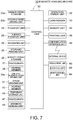
FIG. 7 is a functional block diagram illustrating a configuration of a control system of the banknote handling machine shown inFIG. 1 and the like; -
FIG. 8 schematically illustrates an internal structure of a banknote handling machine according to a second embodiment of the present invention; -
FIG. 9 is a functional block diagram illustrating a configuration of a control system of the banknote handling machine shown inFIG. 8 ; -
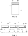
FIG. 10 is a side view showing an example of an operation, performed by a sealing unit, for sealing an opening portion of a banknote storage bag mounted to a mounting unit in the banknote handling machine shown inFIG. 8 ; -
FIG. 11 is a side view showing another example of an operation, performed by the sealing unit, for sealing an opening portion of a banknote storage bag mounted to the mounting unit in the banknote handling machine shown inFIG. 8 ; -
FIG. 12 is a side view showing still another example of an operation, performed by the sealing unit, for sealing an opening portion of a banknote storage bag mounted to the mounting unit in the banknote handling machine shown inFIG. 8 ; -
FIG. 13 is a side view showing still another example of an operation, performed by the sealing unit, for sealing an opening portion of a banknote storage bag mounted to the mounting unit in the banknote handling machine shown inFIG. 8 ; -
FIG. 14 is a side view showing still another example of an operation, performed by the sealing unit, for sealing an opening portion of a banknote storage bag mounted to the mounting unit in the banknote handling machine shown inFIG. 8 ; -
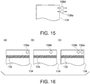
FIG. 15 is a side view showing still another example of an operation, performed by the sealing unit, for sealing an opening portion of a banknote storage bag mounted to the mounting unit in the banknote handling machine shown inFIG. 8 ; -
FIG. 16 is a side view showing still another example of an operation, performed by the sealing unit, for sealing an opening portion of a banknote storage bag mounted to the mounting unit in the banknote handling machine shown inFIG. 8 ; -
FIG. 17 is a side view showing another example of a structure of a banknote storage bag mounted to a mounting unit in the banknote handling machine shown inFIG. 8 ; -
FIG. 18 is a side view showing still another example of a structure of a banknote storage bag mounted to a mounting unit in the banknote handling machine shown inFIG. 8 ; -
FIG. 19 is a perspective view illustrating an outer appearance of a banknote depositing machine according to a third embodiment of the present invention; -
FIG. 20 is a side view showing an internal structure of the banknote depositing machine shown inFIG. 19 ; and -
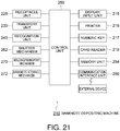
FIG. 21 is a functional block diagram illustrating a configuration of a control system of the banknote depositing machine shown inFIG. 19 and the like. - A first embodiment of the present invention will be described below with reference to the drawings.
FIG. 1 to FIG. 7 illustrate abanknote handling machine 10 according to the first embodiment. - The
banknote handling machine 10 according to the present embodiment is disposed in a front office region or a back office region in a store such as a supermarket, in a bank lobby, or inside a bank, in general. Thebanknote handling machine 10 can perform various handlings such as depositing of banknotes. As shown inFIG. 1 , thebanknote handling machine 10 of the present embodiment has an almost rectangular-parallelepiped-shapedhousing 12. InFIG. 1 , the surface, of thehousing 12, on the left side is a front surface (that is, a surface which an operator faces) of thehousing 12. Anupper assembly 14 and alower assembly 16 are stored in thehousing 12 and able to be drawn forward (specifically, leftward inFIG. 1 ) from the front surface of thehousing 12. Aninlet unit 20 such as a receptacle which takes in a banknote from the outside into the housing 12is disposed at the upper portion on the front surface (the upper portion on the left side surface inFIG. 1 ) of thehousing 12 at theupper assembly 14. Furthermore, an outlet unit 22 for discharging a banknote from thehousing 12 to the outside is disposed below theinlet unit 20 on the front surface (the left side surface inFIG. 1 ) of thehousing 12 at theupper assembly 14. - The
inlet unit 20 is provided with abanknote feeding mechanism 20a for taking in banknotes that are placed in a stacked state in theinlet unit 20 by an operator into thehousing 12 one by one. Atransport unit 24 for transporting banknotes one by one in thehousing 12 is disposed at theupper assembly 14 in thehousing 12 of thebanknote handling machine 10, and the banknotes taken in from theinlet unit 20 by thebanknote feeding mechanism 20a are transported one by one by thetransport unit 24. Arecognition unit 26 is disposed in thetransport unit 24, and therecognition unit 26 recognizes a denomination, authenticity, face/back, fitness, new/old series, a transport state of a banknote taken in into thetransport unit 24 by thebanknote feeding mechanism 20a. - As shown in
FIG. 1 , the outlet unit 22 is connected to thetransport unit 24, and banknotes transported to the outlet unit 22 from thetransport unit 24 are stacked in the outlet unit 22. The outlet unit 22 can be accessed from the outside of thehousing 12, and an operator is allowed to take out the banknotes stacked in the outlet unit 22 from the front surface of thehousing 12. A stackingwheel 22a is disposed at a portion at which thetransport unit 24 is connected to the outlet unit 22, and the stackingwheel 22a rotates in the counterclockwise direction inFIG. 1 . When a banknote is transported from thetransport unit 24 to the outlet unit 22, the stackingwheel 22a rotates in the counterclockwise direction inFIG. 1 in a state where the banknote is held between two vanes of the stackingwheel 22a, whereby the banknote held between the two vanes of the stackingwheel 22a can be stacked in the outlet unit 22 in an aligned state. - In the
upper assembly 14, a tape-type storage/feeding unit 30 is disposed at thetransport unit 24, and a banknote transported from thetransport unit 24 to the storage/feeding unit 30 is stored in the storage/feeding unit 30 and banknotes stored in the storage/feeding unit 30 can be fed out one by one to thetransport unit 24. More specifically, the storage/feeding unit 30 has adrum 30a that can perform both forward rotation and reverse rotation, and one end of a pair of band-like tapes 31 is connected to the outer circumferential surface of thedrum 30a. When banknotes are transported from thetransport unit 24 to the storage/feeding unit 30, the band-like tapes 31 allow the banknotes to be wound together with thetapes 31 on thedrum 30a one by one. Meanwhile, when eachtape 31 is wound back from thedrum 30a by reverse rotation of thedrum 30a, the banknote wound on thedrum 30a is also released from eachtape 31 and fed out to thetransport unit 24. - As shown in
FIG. 1 , in the present embodiment, thelower assembly 16 has a plurality (for example, two) ofbanknote storage mechanisms 32 each of which stores banknotes in abanknote storage bag 34 such as a pouch having an opening portion on one side. Eachbanknote storage mechanism 32 has a pair of holdingmembers 36 that are spaced so as to face each other. The holdingmembers 36 hold two opening portions of thebanknote storage bag 34 which are near the opening of thebanknote storage bag 34 and face each other. The first holding member 36 (specifically, for example, the holdingmember 36 on the right side inFIG. 1 andFIG. 2 ) is fixedly positioned, whereas the second holding member 36 (specifically, for example, the holdingmember 36 on the left side inFIG. 1 andFIG. 2 ) can be moved toward the first holdingmember 36 that is fixedly positioned. As shown inFIG. 2 , each holdingmember 36 is provided with aheating member 38. After a predetermined number of banknotes are stored in thebanknote storage bag 34 held by each holdingmember 36 disposed in thebanknote storage mechanism 32, before thebanknote storage bag 34 is taken out from thebanknote storage mechanism 32, the second holdingmember 36 is moved toward thefirst holding members 36 and the two holdingmembers 36 touch each other. In this state, eachheating member 38 heats an opening portion near the opening of thebanknote storage bag 34, whereby the opening portion of thebanknote storage bag 34 is heat-sealed (thermally sealed). In thebanknote storage mechanism 32, instead of the second holdingmember 36 being moved toward the first holdingmember 36, both the holdingmembers 36 may be moved toward each other up to the center position, and the holdingmembers 36 may touch each other at the center position. - A plurality (two in the example shown in
FIG. 1 ) of divergedtransport units 25 corresponding to thebanknote storage mechanisms 32, respectively, diverge from thetransport unit 24 in theupper assembly 14. A banknote diverted from thetransport unit 24 to the divergedtransport unit 25 is sent from the divergedtransport unit 25 to thebanknote storage bag 34 mounted to thebanknote storage mechanism 32, and stored in thebanknote storage bag 34. - Next, a configuration of the
banknote storage mechanism 32 according to the present embodiment will be described in detail with reference toFIG. 2 to FIG. 4 .FIG. 2 is a side view showing in detail the configuration of thebanknote storage mechanism 32.FIG. 3 is a perspective view of a configuration of the pair of holdingmembers 36 and the like in thebanknote storage mechanism 32 shown inFIG. 2 .FIG. 4 is a perspective view of a configuration of thebanknote storage bag 34, such as a pouch, to be held by each holdingmember 36 in thebanknote storage mechanism 32 shown inFIG. 2 and the like. - As shown in
FIG. 2 , thebanknote storage mechanism 32 has: abanknote sending unit 48 for sending a banknote transported from the divergedtransport unit 25 of theupper assembly 14 to thelower assembly 16, to thebanknote storage bag 34 held by the pair of holdingmembers 36; atemporary storage unit 44 for temporarily storing the banknotes sent by thebanknote sending unit 48; and astage 40 on which the bottom portion of thebanknote storage bag 34 held by the pair of holdingmembers 36 is placed. - As shown in
FIG. 2 , thebanknote sending unit 48 is constituted by a roller and a belt in combination, and sends banknotes transported from the divergedtransport unit 25 of theupper assembly 14 to thelower assembly 16, one by one, to thetemporary storage unit 44, to stack the banknotes on thetemporary storage unit 44. Furthermore, thetemporary storage unit 44 is implemented by a pair of left and right temporary storage units, and eachtemporary storage unit 44 can rotate about a rotating axis of ashaft 44a disposed at the end portion of thetemporary storage unit 44 in the downward direction (that is, directions indicated by arrows inFIG. 2 ). Thestage 40 is implemented by a pair of left and right stages. Eachstage 40 can be moved in the up-down direction and the left-right direction inFIG. 2 . A gap is formed between the paired stages 40. A part of thebanknote storage bag 34 held by the holdingmembers 36 can be extended downward from eachstage 40 through the gap. Eachstage 40 is driven by a stage driving unit 41 (seeFIG. 7 ) such as an electric actuator. - As shown in
FIG. 2 , aheating member 42 is disposed at eachstage 40. Before thebanknote storage bag 34 is taken out from thebanknote storage mechanism 32, the first stage 40 (for example, thestage 40 on the left side inFIG. 2 ) is moved toward the second stage 40 (for example, thestage 40 on the right side inFIG. 2 ), and thestages 40 touch each other. In this state, eachheating member 42 heats a portion, of thebanknote storage bag 34, near the bottom portion thereof, whereby the bottom portion of thebanknote storage bag 34 is heat-sealed (thermally sealed). In thebanknote storage mechanism 32, instead of thefirst stage 40 being moved toward thesecond stage 40, both thestages 40 may be moved toward each other up to the center position and touch each other at the center position. - As shown in
FIG. 3 , apantograph 37 is disposed at the second holdingmember 36 on the left side among the pair of left and right holdingmembers 36, the second holdingmember 36 on the left side is moved toward the first holdingmember 36 on the right side by thepantograph 37, and the holdingmembers 36 touch each other. More specifically, aguide pin 36p is disposed at the end portion of the second holdingmember 36 on the left side, and aframe 36k that supports each holdingmember 36 has a linearlong hole 36q by which theguide pin 36p is guided. Thelong hole 36q extends in theframe 36k in the horizontal direction. When thepantograph 37 is extended, theguide pin 36p disposed at the second holdingmember 36 on the left side is guided along thelong hole 36q, whereby the second holdingmember 36 on the left side is moved toward the first holdingmember 36 on the right side. - As shown in
FIG. 3 , twopins 36a are disposed on the upper surface of each of the paired left and right holdingmembers 36. As shown inFIG. 4 , pairedprotrusions 34a each having twoholes 34b are disposed at portions (that is, the upper end portion of the banknote storage bag 34), near the opening portion, of thebanknote storage bag 34 to be held by each holdingmember 36. When thebanknote storage bag 34 is held by the holdingmembers 36, thepins 36a of the holdingmembers 36 pass through theholes 34b, respectively, disposed in theprotrusions 34a of thebanknote storage bag 34, whereby theprotrusions 34a are held by the holdingmembers 36, respectively. - A
pressing plate 46 is disposed above the pair oftemporary storage units 44. Thepressing plate 46 is provided with a pantograph 47 (seeFIG. 7 , not shown inFIG. 2 ), and thepantograph 47 extends and contracts in the up-down direction inFIG. 2 , whereby thepressing plate 46 can be moved in a range indicated by arrows inFIG. 2 in the up-down direction. As shown inFIG. 2 , by thepressing plate 46 being thus moved downward, when banknotes temporarily stored on thetemporary storage units 44 are stored in thebanknote storage bag 34, the banknotes temporarily stored on thetemporary storage units 44 can be pushed toward thebanknote storage bag 34. - As shown in
FIG. 2 , a one-side aligning lever 39 is disposed below the second holdingmember 36 on the left side among the pair of holdingmembers 36, and banknotes that are stored in thebanknote storage bag 34 held by the pair of holdingmembers 36 are aligned on one side (specifically, the right side inFIG. 2 ) in thebanknote storage bag 34 by the one-side aligning lever 39. More specifically, the one-side aligning lever 39 in the state shown inFIG. 2 is moved rightward by a one-side aligninglever driving unit 39a (seeFIG. 7 ) that includes a pantograph, an electric actuator, and the like. - In the
banknote handling machine 10 of the present embodiment, as described above, theupper assembly 14 and thelower assembly 16 are stored in thehousing 12 and able to be drawn forward (specifically, leftward inFIG. 1 ) from the front surface of thehousing 12. An operation for drawing thelower assembly 16 stored in thehousing 12, from the front surface of thehousing 12 in the forward direction, will be described with reference toFIG. 5 andFIG. 6 . - As shown in
FIG. 5 andFIG. 6 , adoor 12a being disposed at the lower portion on the front surface of thehousing 12 is opened when thelower assembly 16 is drawn outward from thehousing 12. Thebanknote handling machine 10 of the present embodiment includes a door locking unit 64 (seeFIG. 7 ) for locking thedoor 12a in a closed state. In the present embodiment, only a person who has a predetermined authority is allowed to unlock thedoor locking unit 64 of thedoor 12a, and open thedoor 12a. - When banknotes have been stored the
banknote storage bag 34 and before thebanknote storage bag 34 of which the opening portion has been heat-sealed (thermally sealed) by theheating member 38 is collected from thebanknote handling machine 10, an operator firstly unlocks thedoor locking unit 64 of thedoor 12a and opens thedoor 12a, as shown inFIG. 5 . Subsequently, as shown inFIG. 6 , the operator draws thelower assembly 16 forward from the front surface of thehousing 12, whereby the operator is allowed to detach thebanknote storage bag 34 from each holdingmember 36 of thebanknote storage mechanism 32, to collect thebanknote storage bag 34 from thelower assembly 16. - As shown in
FIG. 5 andFIG. 6 , thebanknote handling machine 10 of the present embodiment includes alocking unit 62 that regulates drawing of thelower assembly 16 to the outside of thehousing 12. The lockingunit 62 is required to regulate drawing of thelower assembly 16 to such that thebanknote storage bag 34 held by the holdingmembers 36 cannot be accessed from the outside of thehousing 12. For example, the lockingunit 62 may lock thelower assembly 16 stored in thehousing 12 such that thelower assembly 16 keeps being placed in thehousing 12. In a case where thelower assembly 16 is locked in thehousing 12 by the lockingunit 62, thelower assembly 16 stored in thehousing 12 cannot be drawn forward from the front surface of thehousing 12 even if thedoor 12a is opened. - In the present embodiment, a regulation unit 60 (see
FIG. 7 ) which selectively regulates access to thebanknote storage bag 34 held by the holdingmembers 36 includes the lockingunit 62 and/or thedoor locking unit 64 having the above-described structure. The function of theregulation unit 60 will be described below in detail. - The
banknote handling machine 10 of the present embodiment has acontrol unit 50 that controls the components of thebanknote handling machine 10. More specifically, as shown inFIG. 7 , thebanknote feeding mechanism 20a disposed at theinlet unit 20, a stackingwheel driving unit 22b for driving the stackingwheel 22a disposed at the outlet unit 22, thetransport unit 24, the divergedtransport unit 25, therecognition unit 26, the storage/feeding unit 30, the banknote storage mechanism 32 (specifically, thepantograph 37, theheating member 38, the one-side aligninglever driving unit 39a, thestage driving unit 41, theheating member 42, thetemporary storage unit 44, thepantograph 47, and the banknote sending unit 48), and the like, are connected to thecontrol unit 50. A signal representing a result of recognition of a banknote by therecognition unit 26 is transmitted to thecontrol unit 50, and thecontrol unit 50 controls operations of the components by transmitting an instruction signal to each component of thebanknote handling machine 10. - As shown in
FIG. 7 , an operation/display unit 52, acard reader 53, amemory unit 54, aprinting unit 56, and acommunication interface unit 58 are connected to thecontrol unit 50. As shown inFIG. 1 , the operation/display unit 52 is implemented by, for example, a touch panel disposed on the upper surface of thehousing 12, and the operation/display unit 52 displays information on, for example, a state of handling such as depositing of banknotes in thebanknote handling machine 10, and an inventory amount of banknotes stored in eachbanknote storage bag 34. When an operator operates the operation/display unit 52, various instructions can be provided to thecontrol unit 50. Thecard reader 53 reads an ID card of an operator, and thus performs authentication of authority of the operator. Thememory unit 54 stores information on, for example, a history of handling such as depositing of banknotes in thebanknote handling machine 10, and an inventory amount of banknotes stored in eachbanknote storage bag 34. Theprinting unit 56 prints, on a receipt or the like, information on, for example, a history of handling such as depositing of banknotes in thebanknote handling machine 10 and an inventory amount of banknotes stored in eachbanknote storage bag 34. Thecontrol unit 50 can transmit a signal to and receive a signal from an external device (specifically, for example, higher-order terminal) disposed separately from thebanknote handling machine 10 of the present embodiment, through thecommunication interface unit 58. Specifically, thecontrol unit 50 can transmit information stored in thememory unit 54 through thecommunication interface unit 58 to an external device which is disposed separately from thebanknote handling machine 10. For example, when the banknotes together with thebanknote storage bag 34 are collected by, for example, a guard of a cash-in-transit company, the information on the collected banknotes is transmitted from thecontrol unit 50 to, for example, a computer of the cash-in-transit company through thecommunication interface unit 58. - As shown in
FIG. 7 , theregulation unit 60 is connected to thecontrol unit 50. Theregulation unit 60 includes, for example, the lockingunit 62 and/or thedoor locking unit 64, and selectively regulates access to thebanknote storage bag 34 held by the holdingmembers 36. Specifically, in a case where theregulation unit 60 is the lockingunit 62, the lockingunit 62 regulates the access to thebanknote storage bag 34 held by the holdingmembers 36 because thelower assembly 16 is locked and keeps being placed in thehousing 12 by the lockingunit 62. In a case where theregulation unit 60 is thedoor locking unit 64, thedoor locking unit 64 regulates the access to thebanknote storage bag 34 held by the holdingmembers 36 because thedoor 12a is locked in a closed state by thedoor locking unit 64. In the present embodiment, thecontrol unit 50 controls theregulation unit 60 so as to allow access to thebanknote storage bag 34 held by the holdingmembers 36 in a state where the opening portion of thebanknote storage bag 34 is opened when a predetermined condition is satisfied. More specifically, thecontrol unit 50 controls theregulation unit 60 so as to allow the banknotes to be stored directly into thebanknote storage bag 34 held by the holdingmembers 36 without transporting the banknote through theinlet unit 20, thetransport unit 24, and therecognition unit 26, when a predetermined condition is satisfied. Specifically, in a case where theregulation unit 60 is the lockingunit 62, when the predetermined condition has been satisfied, thelower assembly 16 stored in thehousing 12 is unlocked by the lockingunit 62, and thelower assembly 16 can be drawn forward from the front surface of thehousing 12. In a case where theregulation unit 60 is thedoor locking unit 64, when the predetermined condition has been satisfied, thedoor 12a is unlocked by thedoor locking unit 64, and can be opened. In the present embodiment, theregulation unit 60 may include both thelocking unit 62 and thedoor locking unit 64. Alternatively, theregulation unit 60 of the present embodiment may include one of the lockingunit 62 or thedoor locking unit 64. In the latter case, one of the lockingunit 62 or thedoor locking unit 64 may not be disposed, and only the other thereof may be disposed as theregulation unit 60 in thebanknote handling machine 10. - Next, an operation performed by the
banknote handling machine 10 described above will be described. Thebanknote handling machine 10 performs the operation as described below by thecontrol unit 50 controlling the components of thebanknote handling machine 10. - Firstly, an operation performed by the
banknote handling machine 10 for performing depositing of banknotes will be described. An operator inserts banknotes in theinlet unit 20 and then provides thecontrol unit 50 with an instruction for starting the depositing by using the operation/display unit 52. Then, the banknotes inserted in theinlet unit 20 are taken in into thehousing 12, one by one, by thebanknote feeding mechanism 20a, and transported one by one by thetransport unit 24. Therecognition unit 26 recognizes a denomination, authenticity, face/back, fitness, new/old series, a transport state, and the like of the banknote transported by thetransport unit 24. A banknote recognized as being not normal by therecognition unit 26, that is, a rejected note is transported to the outlet unit 22 by thetransport unit 24, and stacked in the outlet unit 22. Thus, the operator is allowed to manually take out the rejected banknotes stacked in the outlet unit 22 from the front surface of thehousing 12, and, for example, insert again the banknotes in theinlet unit 20. Meanwhile, a banknote recognized as being normal by therecognition unit 26 is transported to the storage/feeding unit 30, and temporarily stored in the storage/feeding unit 30. The number of the banknotes for each denomination and the total monetary amount of banknotes temporarily stored in the storage/feeding unit 30 are displayed on the operation/display unit 52. When the operator confirms the displayed contents, and performs an operation for accepting the depositing, banknotes are fed out one by one from the storage/feeding unit 30 to thetransport unit 24, are diverted from thetransport unit 24 to the divergedtransport unit 25, are sent from the divergedtransport unit 25 to thebanknote storage bag 34, and are stored in thebanknote storage bag 34. - When the
banknote storage bag 34 to which banknotes recognized by therecognition unit 26 is to be transported is in a full state or nearly full state, and no more banknotes recognized by therecognition unit 26 can be stored in thebanknote storage bag 34, the storage/feeding unit 30 may store the more banknotes as a storage unit until the full state or the nearly full state is dissolved. Specifically, the banknotes recognized by therecognition unit 26 are transported to the storage/feeding unit 30, and stored in the storage/feeding unit 30. Thebanknote storage bag 34 in the full state or the nearly full state, is taken out from thebanknote storage mechanism 32 of thelower assembly 16 by, for example, a guard of a cash-in-transit company, and an emptybanknote storage bag 34 is mounted to thebanknote storage mechanism 32. Then, banknotes are fed out one by one from the storage/feeding unit 30 to thetransport unit 24, and transported to thebanknote storage bag 34 by thetransport unit 24. - Next, an operation of storing a banknote transported from the diverged
transport unit 25 of theupper assembly 14 to thelower assembly 16, in thebanknote storage bag 34 held by the pair of holdingmembers 36, in thebanknote storage mechanism 32, will be described. - The banknote transported from the diverged
transport unit 25 of theupper assembly 14 to thelower assembly 16 is sent onto the pair of left and righttemporary storage units 44 by thebanknote sending unit 48, and stacked on thetemporary storage units 44. When a predetermined number of banknotes are stacked on eachtemporary storage unit 44, the eachtemporary storage unit 44 rotates about the axis of theshaft 44a disposed at the end portion in the downward direction (that is, the directions indicated by the arrows inFIG. 2 ), and the banknotes stacked on thetemporary storage units 44 fall from thetemporary storage units 44 due to the own weight, and are stored in thebanknote storage bag 34. When banknotes fall from thetemporary storage units 44, and are stored in thebanknote storage bag 34, thestages 40 are moved downward by thestage driving unit 41, and a storage space for storing the banknotes subsequently sent to thebanknote storage bag 34 from thetemporary storage units 44 is formed in thebanknote storage bag 34. In the present embodiment, when banknotes are sent into thebanknote storage bag 34 held by the holdingmembers 36 and stored in thebanknote storage bag 34, thecontrol unit 50 controls thepantograph 47 so as to press the banknotes temporarily stored in thetemporary storage units 44 into inside of thebanknote storage bag 34 by thepressing plate 46. Thus, when a banknote is left in thetemporary storage units 44, the banknote having been left can be caused to fall from thetemporary storage units 44 and stored in thebanknote storage bag 34. - After banknotes have been stored in the
banknote storage bag 34 held by the holdingmembers 36, and thestages 40 has been moved downward, thecontrol unit 50 may control thepantograph 47 so as to move thepressing plate 46 into thebanknote storage bag 34 and press the bottom of thebanknote storage bag 34 toward eachstage 40 through banknotes stacked in thebanknote storage bag 34. In this case, by the banknotes being pressed into thebanknote storage bag 34 by thepressing plate 46, the banknotes stacked in thebanknote storage bag 34 in a stacked state are compressed in the stacking direction, so that the banknotes stored in thebanknote storage bag 34 in the stacked state can be prevented from collapsing. - Next, an operation performed by the
banknote handling machine 10 for performing collection of banknotes will be described. When a guard of a cash-in-transit company, or the like collects thebanknote storage bag 34 storing banknotes therein, from thebanknote handling machine 10, the guard firstly causes thecard reader 53 to read her/his ID card. When the ID card of the guard has been read by thecard reader 53 to authenticate the authority of the guard, the opening portion of thebanknote storage bag 34 held by the holdingmembers 36 in thebanknote storage mechanism 32 is heat-sealed (thermally sealed) by theheating members 38. After the opening portion of thebanknote storage bag 34 has been sealed, thedoor 12a is unlocked by thedoor locking unit 64, or thelower assembly 16 in thehousing 12 is unlocked by the lockingunit 62. Thus, the guard opens thedoor 12a as shown inFIG. 5 , and then draws thelower assembly 16 forward from the front surface of thehousing 12 as shown inFIG. 6 , whereby thebanknote storage bag 34 held by the holdingmembers 36 in thebanknote storage mechanism 32 can be taken out and collected from thelower assembly 16. - In the
banknote handling machine 10 of the present embodiment, banknotes or the like can be inserted directly from outside of thebanknote handling machine 10 into thebanknote storage bag 34 held by the holdingmembers 36 of thebanknote storage mechanism 32, or banknotes or the like can be taken out from thebanknote storage bag 34 to outside of thebanknote handling machine 10 without transporting the banknotes or the like through theinlet unit 20, thetransport unit 24, and therecognition unit 26. Specifically, in a case where thebanknote storage bag 34 is held by the holdingmembers 36 of thebanknote storage mechanism 32 in a state where the opening portion of thebanknote storage bag 34 is opened, a banknote or a sheet (for example, coupon, voucher, check, foreign banknote, and the like which cannot be handled by the upper assembly 14) other than a banknote can be stored directly from outside into thebanknote storage bag 34 or a banknote or the like can be taken out from thebanknote storage bag 34 by opening thedoor 12a disposed at the lower portion on the front surface of thehousing 12 as shown inFIG. 5 and drawing thelower assembly 16 forward from the front surface of thehousing 12 as show inFIG. 6 . - More specifically, in the present embodiment, when the
control unit 50 determines that a predetermined condition has been satisfied, theregulation unit 60 that includes the lockingunit 62 and/or thedoor locking unit 64 releases the regulation of access to thebanknote storage bag 34, and the guard is allowed the access to thebanknote storage bag 34 held by the holdingmembers 36 in thebanknote storage mechanism 32 in a state where the opening portion of thebanknote storage bag 34 is opened. As the "predetermined condition", various conditions are preset. For example, based on authority of an operator (specifically, information, of an ID card of the operator, which is read by the card reader 53), external information (specifically, information transmitted from an external device through thecommunication interface unit 58 to the control unit 50), internal information (specifically, information inputted by an operator through the operation/display unit 52), whether or not the opening portion of thebanknote storage bag 34 held by the holdingmembers 36 is to be automatically sealed by theheating members 38 is determined. Such an operation will be described below in detail. - For example, the
control unit 50 determines that the predetermined condition has been satisfied in a case where an instruction to insert a sheet such as a banknote directly into thebanknote storage bag 34 held by the holdingmembers 36 of thebanknote storage mechanism 32 without transporting the sheet through theupper assembly 14 is inputted into thecontrol unit 50. The instruction described above is that an instruction to insert a sheet such as a banknote directly into thebanknote storage bag 34 held by the holdingmembers 36 of thebanknote storage mechanism 32 without transporting the sheet through the upper assembly 14 (specifically, theinlet unit 20, thetransport unit 24, and the recognition unit 26) providing though the operation/display unit 52 by an operator, or a signal relating to an instruction is transmitted from an external device through thecommunication interface unit 58 to thecontrol unit 50. Specifically, for example, an additional insertion button is displayed on a standby screen of the operation/display unit 52, and, when an operator presses the additional insertion button, the instruction to insert a sheet such as a banknote directly into thebanknote storage bag 34 held by the holdingmembers 36 of thebanknote storage mechanism 32 without transporting the sheet through theupper assembly 14 is inputted into thecontrol unit 50. when thecontrol unit 50 determines that the predetermined condition has been satisfied, and theregulation unit 60 that includes the lockingunit 62 and/or thedoor locking unit 64 releases the regulation of access to thebanknote storage bag 34, the operator is allowed to open thedoor 12a, and draws thelower assembly 16 forward from the front surface of thehousing 12. Therefore, a banknote or a sheet other than a banknote can be stored directly into thebanknote storage bag 34 held by the holdingmembers 36 in thebanknote storage mechanism 32 in a state where the opening portion of thebanknote storage bag 34 is opened. Thus, when a banknote is to be additionally stored into thebanknote storage bag 34 held by the holdingmembers 36 in thebanknote storage mechanism 32 in a state where the opening portion of thebanknote storage bag 34 is opened, or a sheet (specifically, coupon or voucher, check, foreign banknote, and the like), other than a banknote, which cannot be handled by theupper assembly 14 is to be stored in thebanknote storage bag 34, the sheet such as a banknote can be stored into thebanknote storage bag 34 without transporting the sheet through theinlet unit 20, thetransport unit 24, and therecognition unit 26 of theupper assembly 14. Meanwhile, when the instruction to insert a sheet such as a banknote directly from outside into thebanknote storage bag 34 held by the holdingmembers 36 of thebanknote storage mechanism 32 without transporting the sheet through theupper assembly 14 is not inputted to thecontrol unit 50, theregulation unit 60 regulates the access to thebanknote storage bag 34, and a sheet such as a banknote cannot be stored directly from outside into thebanknote storage bag 34 before the opening portion of thebanknote storage bag 34 held by the holdingmembers 36 is sealed by theheating members 38. - When a sheet such as a banknote is stored directly from outside into the
banknote storage bag 34 without transporting the sheet through theinlet unit 20, thetransport unit 24, and therecognition unit 26 of theupper assembly 14, an operator is allowed to input information on the sheet to the operation/display unit 52. Thus, thecontrol unit 50 can also manage information on the sheet that is stored directly from outside into thebanknote storage bag 34 without transporting the sheet through theupper assembly 14. In this case, information on the sheet that is stored directly from outside into thebanknote storage bag 34 without transporting the sheet through theinlet unit 20, thetransport unit 24, and therecognition unit 26, and information on banknotes that are stored from outside into thebanknote storage bag 34 through theinlet unit 20, thetransport unit 24, and therecognition unit 26, are managed, by thecontrol unit 50, so as to be distinguished from each other. Specifically, the information on a sheet that is stored directly from outside into thebanknote storage bag 34 without transporting the sheet through theinlet unit 20, thetransport unit 24, and therecognition unit 26, and the information on banknotes stored into thebanknote storage bag 34 through theinlet unit 20, thetransport unit 24, and therecognition unit 26, are stored in thememory unit 54 so as to be distinguished from each other. Thus, only information on a sheet such as a banknote that is additionally stored into thebanknote storage bag 34 held by the holdingmembers 36 in thebanknote storage mechanism 32 in a state where the opening portion of thebanknote storage bag 34 is opened, is displayed on, for example, the operation/display unit 52, whereby an operator is allowed to know the information. - In the present embodiment, in a case where, by the predetermined condition having been satisfied, access to the
banknote storage bag 34 held by the holdingmembers 36 is allowed in a state where the opening potion of thebanknote storage bag 34 is opened, an operator is allowed to input into thecontrol unit 50 an instruction to seal the opening portion of thebanknote storage bag 34, through the operation/display unit 52. Thus, until an operator inputs into thecontrol unit 50 an instruction to seal the opening portion of thebanknote storage bag 34, a sheet such as a banknote can be stored directly outside into thebanknote storage bag 34 without transporting the sheet through theinlet unit 20, thetransport unit 24, and therecognition unit 26 of theupper assembly 14. Furthermore, when the predetermined condition is satisfied, and the access to thebanknote storage bag 34 held by the holdingmembers 36 is allowed in a state where the opening portion of thebanknote storage bag 34 is opened, thebanknote storage bag 34 can be collected in the condition that thecard reader 53 reads an ID card of a guard of a cash-in-transit company to authenticate authority of the guard, and the opening portion of thebanknote storage bag 34 held by the holdingmembers 36 is sealed by eachheating member 38. - In the present embodiment, in a case where authority of an operator who is authenticated based on the ID card having been read by the
card reader 53 is a predetermined authority (for example, manager, a store manager, or the like of a store), thecontrol unit 50 may determine that the predetermined condition has been satisfied. In this case, when the authority of the operator represents, for example, a manager, a store manager, or the like of the store, such a manager, store manager, or the like is allowed to open thedoor 12a and draw thelower assembly 16 forward from the front surface of thehousing 12. Thus, the manager, store manager, or the like is allowed to insert a banknote or a sheet other than a banknote directly from outside into thebanknote storage bag 34 held by the holdingmembers 36 in thebanknote storage mechanism 32 in a state where the opening portion of thebanknote storage bag 34 is opened, or take out a banknote or the like from thebanknote storage bag 34 to outside. Meanwhile, in a case where the authority of an operator who is authenticated based on the ID card having been read by thecard reader 53 represents an ordinary clerk or the like, the predetermined condition is not satisfied. Therefore, such an ordinary clerk or the like is not allowed to access thebanknote storage bag 34 held by each holdingmember 36 in thebanknote storage mechanism 32 in a state where the opening portion of thebanknote storage bag 34 is opened. Therefore, removal of a banknote from thebanknote storage bag 34 by a malicious clerk or the like can be prevented. - In the present embodiment, an operator may input a temporary time-limited password (one time password) to the operation/
display unit 52. In this case, when the time-limited password inputted to the operation/display unit 52 by the operator is correct, thecontrol unit 50 determines that the predetermined condition has been satisfied. In another example, thecard reader 53 reads an ID card of each of a plurality of operators, and, when the authorities of the plurality of operators represent a combination of predetermined authorities which have been preset, thecontrol unit 50 may determine that the predetermined condition has been satisfied. Specifically, for example, only when an ID card of each of a manager or store manager of a store and a guard of a cash-in-transit company has been read by thecard reader 53, thecontrol unit 50 may determine that the predetermined condition has been satisfied. In this case, only when a plurality of operators having different authorities operate thebanknote handling machine 10, thebanknote storage bag 34 held by the holdingmembers 36 in thebanknote storage mechanism 32 can be accessed in a state where the opening portion of thebanknote storage bag 34 is opened, and theft can be more effectively prevented. - In the present embodiment, in a case where access to the
banknote storage bag 34 held by each holdingmember 36 in eachbanknote storage mechanism 32 is allowed in a state where the opening portion of thebanknote storage bag 34 is opened, the opening portion of thebanknote storage bag 34 is sealed by theheating members 38 in a manner different from a manner for a case where access to thebanknote storage bag 34 is not allowed. Specifically, in a case where access to thebanknote storage bag 34 held by the holdingmembers 36 is allowed in a state where the opening portion of thebanknote storage bag 34 is opened, when the opening portion of thebanknote storage bag 34 is sealed by theheating members 38, a specific character or mark is formed near a portion at which the opening portion of the banknote storage bag 34is sealed, or the opening portion of thebanknote storage bag 34 is sealed at a plurality of portions. In this case, when a guard of a cash-in-transit company, or the like collects thebanknote storage bag 34 from thelower assembly 16 of thebanknote handling machine 10, the guard or the like can easily know that a sheet such as a banknote may have been additionally stored into thebanknote storage bag 34 or a banknote may have been taken out from thebanknote storage bag 34. In another example, in a case where an operator inputs, through the operation/display unit 52, information on a sheet such as a banknote that has been stored directly into thebanknote storage bag 34 without transporting the sheet through theupper assembly 14 by access to thebanknote storage bag 34 held by the holdingmembers 36 being allowed in a state where the opening portion of thebanknote storage bag 34 is opened, when the opening portion of thebanknote storage bag 34 is sealed by theheating members 38, a character or a mark indicating that a sheet such as a banknote has been stored directly into thebanknote storage bag 34 may be formed near a portion at which the opening portion of thebanknote storage bag 34 is sealed. - When the opening portion of the
banknote storage bag 34 is sealed by theheating members 38, a not-illustrated printing unit may print a code such as a barcode or a two-dimensional code near the opening portion of thebanknote storage bag 34. In this case, in a case where access to thebanknote storage bag 34 held by each holdingmember 36 has been allowed in a state where the opening portion of thebanknote storage bag 34 is opened, information indicating that access to thebanknote storage bag 34 has been allowed may be included in information on the code printed on thebanknote storage bag 34. Alternatively, in a case where an operator inputs, through the operation/display unit 52, information on a sheet such as a banknote that has been stored directly into thebanknote storage bag 34 without transporting the sheet through theupper assembly 14, information on the sheet stored into thebanknote storage bag 34 may be included in information on the code printed on thebanknote storage bag 34. - In a case where access to the
banknote storage bag 34 held by the holdingmembers 36 in thebanknote storage mechanisms 32 is allowed in a state where the opening portion of thebanknote storage bag 34 is opened, when thebanknote storage bag 34 of which the opening portion is not sealed by theheating members 38 is detached from the holdingmembers 36, a warning message may be displayed on the operation/display unit 52 or a warning sound may be outputted. In this case, in a case where access to thebanknote storage bag 34 held by the holdingmembers 36 is allowed, thebanknote storage bag 34 can be prevented from being carried away from thelower assembly 16 by a malicious third party. - In the
banknote handling machine 10 of the present embodiment, the number of thebanknote storage mechanisms 32 disposed is two, and thebanknote storage bag 34 is held by the holdingmembers 36 in thebanknote storage mechanisms 32. The authority of a store may be allocated to thebanknote storage bag 34 corresponding to the firstbanknote storage mechanism 32, and the authority of a cash-in-transit company may be allocated to thebanknote storage bags 34 corresponding to both thebanknote storage mechanisms 32. In this case, predetermined conditions corresponding to the twobanknote storage bags 34, respectively, held by the holdingmembers 36, are set. More specifically, in a case where the authority of an operator who is authenticated based on the ID card having been read by thecard reader 53 represents, for example, a manager, store manager, or the like of the store, theregulation unit 60 releases the regulation of the access to only thebanknote storage bag 34 to which the authority of the store is allocated. Thus, when the manager, store manager, or the like of the store inputs, through the operation/display unit 52, an instruction for accessing thebanknote storage bag 34 to which the authority of the store is allocated, thedoor 12a is opened and thelower assembly 16 is drawn forward from the front surface of thehousing 12, whereby a banknote or the like can be stored directly into thebanknote storage bag 34 to which the authority of the store is allocated, or a banknote or the like can be taken out from thebanknote storage bag 34. Thus, the manager, store manager, or the like of the store is allowed to perform depositing of the banknotes taken out from thebanknote storage bag 34, as change fund, into a money change machine installed at a point-of-sale (POS) register, or replenish an automated teller machine (ATM) with the banknotes. In a case where sheets (for example, voucher or check, coupon, or the like) other than banknotes have been stored in thebanknote storage bag 34 in thebanknote handling machine 10, the manager, store manager, or the like of the store is allowed to take out such a sheet from thebanknote storage bag 34, and perform visual confirmation. In a case where the authority of an operator who is authenticated based on an ID card having been read by thecard reader 53 represents, for example, a manager, store manager, or the like of the store, when the operator inputs, through the operation/display unit 52, an instruction for accessing thebanknote storage bag 34 to which the authority of the store is allocated, the opening portion of thebanknote storage bag 34 to which the authority of the cash-in-transit company is allocated is automatically sealed by theheating members 38. Thus, the manager, store manager, or the like of the store is not allowed to take out banknotes from thebanknote storage bag 34 to which the authority of the cash-in-transit company is allocated. - In a case where the authority of an operator who is authenticated based on an ID card having been read by the
card reader 53 represents, for example, a guard of a cash-in-transit company, theregulation unit 60 releases the regulation of access to all thebanknote storage bags 34. Thus, when the guard of the cash-in-transit company inputs, through the operation/display unit 52, an instruction for accessing thebanknote storage bag 34, thedoor 12a is opened and thelower assembly 16 is drawn forward from the front surface of thehousing 12, whereby banknotes or the like can be stored directly into all thebanknote storage bag 34, or banknotes or the like can be taken out from all thebanknote storage bags 34. - In another aspect, in the
lower assembly 16, thebanknote storage bag 34 to which the authority of the store is allocated is disposed on the front surface side, and thebanknote storage bag 34 to which the authority of the cash-in-transit company is allocated is disposed on the far side, and, in a case where the authority of an operator who is authenticated based on an ID card having been read by thecard reader 53 represents, for example, the manager, store manager, or the like of the store, when the operator inputs, through the operation/display unit 52, an instruction for accessing thebanknote storage bag 34 to which the authority of the store is allocated, only the half portion of thelower assembly 16 may be drawn from thehousing 12. Specifically, among the twobanknote storage bags 34 held by the holdingmembers 36, thebanknote storage bag 34 on the front surface side is exposed outside thehousing 12, whereas a position up to which thelower assembly 16 is drawn is regulated by the lockingunit 62 such that thebanknote storage bag 34 on the far side is left stored in thehousing 12. Thus, when only the half portion of thelower assembly 16 can be drawn from thehousing 12, the operator is allowed to access thebanknote storage bag 34 to which the authority of the store is allocated, whereas the operator is not allowed to access thebanknote storage bag 34 to which the authority of the cash-in-transit company is allocated. - In the
banknote handling machine 10 of the present embodiment, among the twobanknote storage bags 34 disposed in thebanknote storage mechanisms 32, respectively, the authority of the cash-in-transit company may be automatically allocated to thebanknote storage bag 34 in which the number of stored banknotes is greater, and the authority of the store may be automatically allocated to thebanknote storage bag 34 in which the number of stored banknotes is smaller. In this case, when the authority of an operator who is authenticated based on an ID card having been read by thecard reader 53 represents, for example, a manager, store manager, or the like of the store, regulation, the regulation unit 60releases the regulation of access to only thebanknote storage bag 34 in which the number of stored banknotes is smaller. Thus, when the manager, store manager, or the like of the store inputs, through the operation/display unit 52, an instruction for accessing thebanknote storage bag 34 to which the authority of the store is allocated, thedoor 12a is opened and thelower assembly 16 is drawn forward from the front surface of thehousing 12, whereby thebanknote storage bag 34 in which the number of stored banknotes is smaller can be accessed. Thus, the manager, store manager, or the like of the store is allowed to insert a sheet (for example, voucher or check, coupon, or the like) other than a banknote directly from outside into thebanknote storage bag 34 in which the number of stored banknotes is smaller. - The
banknote handling machine 10, according to the present embodiment, having the above-described configuration, includes: the holdingmembers 36 as a holding unit for holding a storage bag in a state where the opening portion of thebanknote storage bag 34 is opened or in a state where the opening portion of thebanknote storage bag 34 is sealed; theheating members 38 as a sealing unit for sealing the opening portion of thebanknote storage bag 34 held by each holdingmember 36; and theregulation unit 60 for selectively regulating access to thebanknote storage bag 34 held by each holdingmember 36. Thecontrol unit 50 controls theregulation unit 60 so as to allow access to thebanknote storage bag 34 held by the holdingmembers 36 in a state where the opening portion of thebanknote storage bag 34 is opened, when a predetermined condition is satisfied. Thus, when the predetermined condition is satisfied, access to thebanknote storage bag 34 held by each holdingmember 36 is allowed in a state where the opening portion of thebanknote storage bag 34 is opened, whereby a sheet such as a banknote can be additionally stored into thebanknote storage bag 34 held by the holdingmembers 36 in a state where the opening portion of thebanknote storage bag 34 is opened, or a banknote can be taken out from thebanknote storage bag 34. - More specifically, in a conventional banknote handling machine, when a banknote storage bag such as a pouch is collected by, for example, a guard of a cash-in-transit company, the opening portion of the banknote storage bag is automatically sealed by a sealing unit. Meanwhile, since before, there has been a request for manually inserting a banknote or a sheet such as a check directly into a banknote storage bag held by each holding member in a state where the opening portion of the banknote storage bag is opened, without transporting the banknote or the sheet through an upper assembly such as an inlet unit, a transport unit, and a recognition unit. However, a conventional banknote handling machine has a problem that such additional insertion of a sheet cannot be performed. When, for example, a guard of a cash-in-transit company collects a banknote storage bag such as a pouch, since a service charge is determined per one banknote storage bag, the store wants to maximize the number of banknotes or the like to be stored in the banknote storage bag. However, a conventional banknote handling machine allows only a guard of a cash-in-transit company, or the like to access the banknote storage bag. Therefore, the request of the store for maximizing the number of banknotes to be stored in the banknote storage bag by manually inserting banknotes cannot be satisfied. Meanwhile, in a case where the banknote storage bag is excessively filled with banknotes, when the opening portion of the banknote storage bag is heat-sealed by each heating member, banknotes near the opening portion of the banknote storage bag are held by each heating member, which causes insufficient sealing of the opening portion of the banknote storage bag. Therefore, a guard of a cash-in-transit company, or the like wants to check a banknote storage bag in advance before the opening portion of the banknote storage bag is sealed, and, when the banknote storage bag is excessively filled with banknotes, the guard wants to take out some of the banknotes from the banknote storage bag. Meanwhile, in the
banknote handling machine 10 of the present embodiment, in a case where a predetermined condition has been satisfied, access to thebanknote storage bag 34 held by each holdingmember 36 is allowed in a state where the opening portion of thebanknote storage bag 34 is opened, so that the various requests as described above can be satisfied. - In the
banknote handling machine 10 of the present embodiment, as described above, at least the holdingmembers 36 are disposed, and thelower assembly 16 is disposed as a drawer unit which is drawn outward from thehousing 12, and theregulation unit 60 includes the lockingunit 62 that regulates drawing of thelower assembly 16 outward from thehousing 12. The lockingunit 62 may regulate thelower assembly 16 such that the entirety of thelower assembly 16 is stored in thehousing 12. The lockingunit 62 may regulate the position of thelower assembly 16 such that thebanknote storage bag 34 held by the holdingmember 36 of thelower assembly 16 cannot be substantially accessed from the outside of thehousing 12. The lockingunit 62 may be disposed inside thehousing 12 or disposed outside thehousing 12 to regulate the operation of drawing thelower assembly 16, from the outside of thehousing 12. Thecontrol unit 50 controls the lockingunit 62 so as to allow thelower assembly 16 to be drawn outward from thehousing 12 when a predetermined condition has been satisfied. In this case, when the predetermined condition has been satisfied, an operator draws thelower assembly 16 outward from thehousing 12, whereby thebanknote storage bag 34 held by each holdingmember 36 that is disposed in thelower assembly 16 in a state where the opening portion of thebanknote storage bag 34 is opened can be accessed. - In the
banknote handling machine 10 of the present embodiment, as described above, thedoor 12a is disposed in thehousing 12 and is opened when thelower assembly 16 as a drawer unit is drawn outward from thehousing 12. Theregulation unit 60 includes thedoor locking unit 64 for locking thedoor 12a in a closed state. Thecontrol unit 50 controls thedoor locking unit 64 so as to cancel locking of thedoor 12a in the closed state when a predetermined condition has been satisfied. In this case, when the predetermined condition has been satisfied, an operator opens thedoor 12a and draws thelower assembly 16 outward from thehousing 12, whereby thebanknote storage bag 34 held by each holdingmember 36 that is disposed in thelower assembly 16 can be accessed in a state where the opening portion of thebanknote storage bag 34 is opened. Thedoor 12a may not be disposed on the front surface of thehousing 12, and may be disposed on the rear surface or the side surface of thehousing 12. A plurality of holdingmembers 36 may be disposed and a plurality ofdoors 12a corresponding to the plurality of holdingmembers 36, respectively, may be separately disposed. As described above, theregulation unit 60 may include both thelocking unit 62 and thedoor locking unit 64. Alternatively, theregulation unit 60 may include one of the lockingunit 62 or thedoor locking unit 64. In the latter case, one of the lockingunit 62 or thedoor locking unit 64 may not be disposed, and only the other thereof may be disposed as theregulation unit 60 in thebanknote handling machine 10. - In the
banknote handling machine 10 of the present embodiment, as described above, theinlet unit 20 as a taking-in unit for taking in banknotes into thehousing 12, thetransport unit 24 for transporting banknotes that are taken in into thehousing 12 by theinlet unit 20, and therecognition unit 26 for performing recognition of banknotes transported by thetransport unit 24 are disposed. Thecontrol unit 50 controls theregulation unit 60 so as to allow a sheet such as a banknote to be stored into thebanknote storage bag 34 held by each holdingmember 36 without transporting the sheet through theinlet unit 20, thetransport unit 24, and therecognition unit 26, when a predetermined condition has been satisfied. In this case, when a sheet such as a banknote is allowed to be stored into thebanknote storage bag 34 held by each holdingmember 36, an operator is allowed to insert the sheet such as a banknote directly into thebanknote storage bag 34 without transporting the sheet through theinlet unit 20, thetransport unit 24, and therecognition unit 26. - In the
banknote handling machine 10 of the present embodiment, as described above, when an instruction (that is, an instruction for inserting a sheet such as a banknote directly into the banknote storage bag 34) for inserting a sheet such as a banknote into thebanknote storage bag 34 held by each holdingmember 36 without transporting the sheet through theinlet unit 20, thetransport unit 24, and therecognition unit 26, is inputted, thecontrol unit 50 determines that the predetermined condition has been satisfied. In this case, an additional insertion button is displayed on the operation/display unit 52, as an instruction unit for providing an instruction for inserting a sheet such as a banknote in thebanknote storage bag 34 held by each holdingmember 36 without transporting the sheet through theinlet unit 20, thetransport unit 24, and therecognition unit 26, and, when the additional insertion button is operated, an instruction for inserting a sheet such as a banknote into thebanknote storage bag 34 held by each holdingmember 36 without transporting the sheet through theinlet unit 20, thetransport unit 24, and therecognition unit 26, may be inputted into thecontrol unit 50. - In the
banknote handling machine 10 of the present embodiment, as described above, information on a sheet such as a banknote that is stored into thebanknote storage bag 34 held by each holdingmember 36 without transporting the sheet through theinlet unit 20, thetransport unit 24, and therecognition unit 26, can be inputted to the operation/display unit 52. In this case, the operation/display unit 52 functions as an input unit for inputting information on a sheet such as a banknote that is stored into thebanknote storage bag 34 held by each holdingmember 36 without transporting the sheet through theinlet unit 20, thetransport unit 24, and therecognition unit 26. Thus, thecontrol unit 50 can manage information on a sheet such as a banknote that is stored directly into thebanknote storage bag 34. According to the present embodiment, information (that is, information on a sheet such as a banknote that is stored directly into the banknote storage bag 34) on a sheet such as a banknote that is stored into thebanknote storage bag 34 held by each holdingmember 36 without transporting the sheet through theinlet unit 20, thetransport unit 24, and therecognition unit 26, and information (that is, information on banknotes stored in thebanknote storage bag 34 in depositing of the banknotes as described above) on banknotes that are stored into thebanknote storage bag 34 held by each holdingmember 36 through theinlet unit 20, thetransport unit 24, and therecognition unit 26 are managed, by thecontrol unit 50, so as to be distinguished from each other. - In the
banknote handling machine 10 of the present embodiment, as described above, thecard reader 53 is disposed as an authentication unit for performing authentication of authority of an operator, and, when the authority of an operator who is authenticated by thecard reader 53 is a predetermined authority, thecontrol unit 50 may determine that the predetermined condition has been satisfied. The authentication unit for performing authentication of the authority of an operator is not limited to thecard reader 53. In another aspect, by an operator inputting an identification number and password of the operator to the operation/display unit 52, the authentication of the operator may be performed. In this case, the operation/display unit 52 functions as the authentication unit for performing authentication of the authority of an operator. - In the
banknote handling machine 10 of the present embodiment, as described above, a plurality of sets (specifically, two sets) of a pair of holdingmembers 36 are disposed. The predetermined condition corresponding to each of the plurality (specifically, two) of thebanknote storage bags 34 held by the holdingmembers 36 is set, and, when the predetermined condition corresponding to thebanknote storage bag 34 is satisfied for each of thebanknote storage bags 34 held by the respective sets of holdingmembers 36, thecontrol unit 50 controls theregulation unit 60 so as to allow access to the correspondingbanknote storage bag 34 held by the holdingmembers 36 in a state where the opening portion of thebanknote storage bag 34 is opened. Thus, for example, when the authority of the store is allocated to the firstbanknote storage bag 34, and the authority of the cash-in-transit company is allocated to the secondbanknote storage bag 34, a specific operator of the store is allowed to access only the firstbanknote storage bag 34 to which the authority of the store is allocated. - In the
banknote handling machine 10 of the present embodiment, as described above, in a case where access to thebanknote storage bag 34 held by each holdingmember 36 is allowed in a state where the opening portion of thebanknote storage bag 34 is opened, eachheating member 38 that functions as a sealing unit seals the opening portion of thebanknote storage bag 34 in a manner different from a manner for a case where access to thebanknote storage bag 34 is not allowed. In this case, when, for example, a guard of a cash-in-transit company collects thebanknote storage bag 34 from thelower assembly 16 of thebanknote handling machine 10, the guard can easily know that a sheet such as a banknote may have been additionally stored into thebanknote storage bag 34, or a banknote may have been taken out from thebanknote storage bag 34. - The
banknote handling machine 10 of the present embodiment and the banknote handling method performed by thebanknote handling machine 10 are not limited to the above-described aspects, and various modifications can be added. - For example, the
regulation unit 60 for selectively regulating access to thebanknote storage bag 34 held by each holdingmember 36 is not limited to thelocking unit 62 for locking thelower assembly 16 in thehousing 12, and/or thedoor locking unit 64 for locking thedoor 12a in a closed state. A unit, other than the above-describedlocking unit 62 and/ordoor locking unit 64, which can selectively regulate access to thebanknote storage bag 34 held by each holdingmember 36 can be used as theregulation unit 60. - A predetermined condition used for determining whether or not access to the
banknote storage bag 34 held by each holdingmember 36 is to be allowed in a state where the opening portion of thebanknote storage bag 34 is opened, is not limited to a condition that an instruction for inserting a sheet such as a banknote directly into thebanknote storage bag 34 held by each holdingmember 36 without transporting the sheet through theinlet unit 20, thetransport unit 24, and therecognition unit 26, has been inputted, or a condition that authority of an operator who has been authenticated by the authentication unit such as thecard reader 53 is a predetermined authority. A condition other than the above-described conditions can be used as the predetermined condition used for determining whether or not access to thebanknote storage bag 34 held by each holdingmember 36 is to be allowed in a state where the opening portion of thebanknote storage bag 34 is opened. - A second embodiment of the present invention will be described below with reference to the drawings.
FIG. 8 to FIG. 18 illustrate abanknote handling machine 110 according to a second embodiment. In the description for thebanknote handling machine 110 according to the second embodiment, the same components as described for thebanknote handling machine 10 according to the first embodiment are denoted by the same reference numerals, and description thereof is omitted. - As shown in
FIG. 8 , in thebanknote handling machine 110 of the present embodiment, thelower assembly 16 includes a plurality (two in the example shown inFIG. 8 ) of mountingunits 132 to whichbanknote storage bags 134 such as pouches can be mounted. More specifically, the two mountingunits 132 are aligned in thelower assembly 16 along a direction (that is, leftward direction inFIG. 8 ) of drawing of thelower assembly 16 from thehousing 12. - Each mounting
unit 132 has a pair of holdingmembers 132a that are spaced so as to face each other. Two portions, of thebanknote storage bag 134, which are near the opening portion of thebanknote storage bag 134 and which face each other are held by the holdingmembers 132a, respectively. Thefirst holding member 132a is fixedly positioned, whereas thesecond holding member 132a can be moved toward the first holdingmember 132a that is fixedly positioned. Each mountingunit 132 is provided with asealing unit 138 for sealing the opening portion of thebanknote storage bag 134 mounted to the mountingunit 132. The sealingunit 138 has a sealingmember 138a for sealing the opening portion of thebanknote storage bag 134 mounted to the mountingunit 132. The sealingmember 138a seals, by heat, the opening portion of thebanknote storage bag 134 mounted to the mountingunit 132. More specifically, the sealingmember 138a is disposed in each holdingmember 132a. After banknotes are stored in thebanknote storage bag 134 mounted to the mountingunit 132, thesecond holding members 132a is moved toward thefirst holding members 132a, and the holdingmembers 132a touch each other. In this state, each sealingmember 138a heats a portion, near the opening portion, of thebanknote storage bag 134, whereby the opening portion of thebanknote storage bag 134 is heat-sealed (thermally sealed). In each mountingunit 132, instead of thesecond holding member 132a being moved toward the first holdingmember 132a, both the holdingmembers 132a may be moved toward each other to touch the holdingmembers 132a to each other. - As described below, the sealing
unit 138 may have aprinting member 138b for performing printing on thebanknote storage bag 134 mounted to the mountingunit 132, or a markingmember 138c for marking thebanknote storage bag 134 mounted to the mountingunit 132. The sealingunit 138 may include a cuttingmember 138d for partially cutting thebanknote storage bag 134 mounted to the mountingunit 132. The cuttingmember 138d forms a hole at a portion, near the opening portion, of thebanknote storage bag 134 mounted to the mountingunit 132, or forms a cut portion at an edge of thebanknote storage bag 134. Functions of theprinting member 138b, the markingmember 138c, and the cuttingmember 138d will be described below in detail. In the present embodiment, theprinting member 138b, the markingmember 138c, and the cuttingmember 138d are used as components each of which is a part of thesealing unit 138. However, at least one or the entirety of theprinting member 138b, the markingmember 138c, and the cuttingmember 138d may be components separate from the sealingunit 138. - In each mounting
unit 132, a temporary storage unit for temporarily holding banknotes transported from thetransport unit 24, and a pressing plate for pressing, into thebanknote storage bag 134, the banknote that are temporarily stored in the temporary storage unit are disposed above the pair of holdingmembers 132a, which are not shown inFIG. 8 . Specifically, banknotes transported from thetransport unit 24 to each mountingunit 132 are stacked on the temporary storage unit in a stacked state, and, when the banknotes stacked in the temporary storage unit in the stacked state are stored in thebanknote storage bag 134, the pressing plate is moved downward and the banknotes stacked in the temporary storage unit are pressed downward and sent into thebanknote storage bag 134. When a predetermined number of banknotes are stored in thebanknote storage bag 134, the pressing plate is moved downward into thebanknote storage bag 134, and the banknotes stored in thebanknote storage bag 134 are pressed downward and compressed by the pressing plate. - An operator draws the
lower assembly 16 forward (that is, the leftward inFIG. 8 ) from the front surface of thehousing 12, whereby the operator is allowed to detach thebanknote storage bag 134 storing the banknotes, from the mountingunit 132, or mount an emptybanknote storage bag 134 to the mountingunit 132. - In the
upper assembly 14, a plurality (two in the example shown inFIG. 8 ) of divergedtransport units 25 corresponding to the mountingunits 132, respectively diverge from thetransport unit 24. A banknote that is diverted from thetransport unit 24 into the divergedtransport unit 25 is sent from the divergedtransport unit 25 to thebanknote storage bag 134 mounted to each mountingunit 132, and stored in thebanknote storage bag 134. - The
banknote handling machine 110 of the present embodiment includes acontrol unit 150 that controls the components of thebanknote handling machine 110. More specifically, as shown inFIG. 9 , thebanknote feeding mechanism 20a disposed at theinlet unit 20, the stackingwheel driving unit 22b for driving the stackingwheel 22a disposed at the outlet unit 22, thetransport unit 24, the divergedtransport unit 25, therecognition unit 26, the storage/feeding unit 30, the mountingunit 132, the sealingunit 138, and the like are connected to thecontrol unit 150. A signal representing a result of recognition of a banknote by therecognition unit 26 is transmitted to thecontrol unit 150, and thecontrol unit 150 controls operations of the components by transmitting an instruction signal to each component of thebanknote handling machine 110. - As shown in
FIG. 9 , the operation/display unit 52, thememory unit 54, theprinting unit 56, and thecommunication interface unit 58 are connected to thecontrol unit 150. As shown inFIG. 8 , the operation/display unit 52 is implemented by, for example, a touch panel disposed on the upper surface of thehousing 12. The operation/display unit 52 displays information on, for example, a state of handling such as depositing of banknotes in thebanknote handling machine 110, and an inventory amount of banknotes stored in eachbanknote storage bag 134. By an operator operating the operation/display unit 52, the operator is allowed to provide thecontrol unit 150 with various instructions. - The
memory unit 54 stores information on, for example, a history of handling such as depositing of banknotes in thebanknote handling machine 110, and an inventory amount of banknotes stored in eachbanknote storage bag 134. Theprinting unit 56 prints, on a receipt or the like, information on, for example, a history of handling such as depositing of banknotes in thebanknote handling machine 110 and an inventory amount of banknotes stored in eachbanknote storage bag 134. Thecontrol unit 150 can transmit a signal to and receive a signal from an external device (specifically, for example, higher-order terminal) disposed separately from thebanknote handling machine 110 of the present embodiment, through thecommunication interface unit 58. For example, when thebanknote storage bag 134 is collected by, for example, a guard of a cash-in-transit company, thecontrol unit 150 transmits the information on thebanknote storage bag 134 to the cash-in-transit company through thecommunication interface unit 58. - As shown in
FIG. 9 , asetting unit 140 for selecting and setting a sealing method for sealing the opening portion of thebanknote storage bag 134 from a plurality of sealing methods, based on a result of recognition by therecognition unit 26 is connected to thecontrol unit 150. The function of thesetting unit 140 will be described below in detail. - As shown in
FIG. 9 , apower switch 142 is connected to thecontrol unit 150. Thepower switch 142 is disposed in thehousing 12 of thebanknote handling machine 110, and thebanknote handling machine 110 operates or stops by an operator setting thepower switch 142 to be on or off. - Next, an operation performed by the
banknote handling machine 110 having such a configuration will be described. The operation is performed by thebanknote handling machine 110 as described below by thecontrol unit 150 controlling each component of thebanknote handling machine 110. - Firstly, an operation performed by the
banknote handling machine 110 for depositing of banknotes will be described. An operator inserts banknotes in theinlet unit 20 and then provides thecontrol unit 150 with an instruction for starting the depositing by using the operation/display unit 52. Then, the banknotes inserted in theinlet unit 20 are taken in into thehousing 12 one by one by thebanknote feeding mechanism 20a, and transported one by one by thetransport unit 24. Therecognition unit 26 recognizes a denomination, authenticity, face/back, fitness, new/old series, a transport state, and the like of the banknote transported by thetransport unit 24. An image of the banknote is taken by an image sensor of therecognition unit 26, and the serial number of the banknote is obtained based on the image of the banknote. Information on the serial number of the banknote obtained by therecognition unit 26 is stored in thememory unit 54. A banknote recognized as being not normal by therecognition unit 26, that is, a rejected note is transported to the outlet unit 22 by thetransport unit 24, and stacked in the outlet unit 22. Thus, for example, the operator is allowed to manually take out the rejected banknotes stacked in the outlet unit 22 from the front surface of thehousing 12, and to insert again the banknotes in theinlet unit 20. Meanwhile, banknotes recognized as being normal by therecognition unit 26 are diverted from thetransport unit 24 to the divergedtransport unit 25, sent from the divergedtransport unit 25 to thebanknote storage bag 134, and stored in thebanknote storage bag 134. - In a case where the
banknote storage bag 134 to which a banknote recognized by therecognition unit 26 is to be transported, is in a full state or nearly full state, and the banknote cannot be stored in thebanknote storage bag 134, the banknote recognized by therecognition unit 26 is transported to the storage/feeding unit 30, and stored in the storage/feeding unit 30. When thebanknote storage bag 134 in the full state or nearly full state is detached from the mountingunit 132 of thelower assembly 16 by, for example, a guard of a cash-in-transit company, or a clerk of a store, and an emptybanknote storage bag 134 is mounted to the mountingunit 132, banknotes are fed out one by one from the storage/feeding unit 30 to thetransport unit 24, and transported to thebanknote storage bag 134 by thetransport unit 24. - When the
banknote storage bag 134 in the full state or nearly full state is detached from the mountingunit 132 of thelower assembly 16 by, for example, a guard of a cash-in-transit company or a clerk of a store, the opening portion of thebanknote storage bag 134 mounted to the mountingunit 132 is sealed by the sealingunit 138. Specifically, thesecond holding member 132a is moved toward the first holdingmember 132a, and the holdingmembers 132a touch each other. In this state, each sealingmember 138a heats a portion, near the opening portion, of thebanknote storage bag 134, whereby the opening portion of thebanknote storage bag 134 is heat-sealed (thermally sealed). - In the present embodiment, a banknote to be stored in the
banknote storage bag 134 mounted to the mountingunit 132 is recognized by therecognition unit 26, and thesetting unit 140 selects and sets a sealing method for sealing the opening portion of thebanknote storage bag 134 by the sealingunit 138 from a plurality of sealing methods, based on the result of recognition by therecognition unit 26. Thecontrol unit 150 controls thesealing unit 138 so as to seal the opening portion of thebanknote storage bag 134 mounted to the mountingunit 132, based on the sealing method having been set by thesetting unit 140. Thememory unit 54 may store correspondence between the sealing method and the result of recognition by therecognition unit 26, and thesetting unit 140 may read and set the sealing method corresponding to the result of recognition by therecognition unit 26, from thememory unit 54. Furthermore, the correspondence, stored in thememory unit 54, between the sealing method and the result of recognition by therecognition unit 26, may be changed by input through the operation/display unit 52. Such an operation will be described below in detail. - The
setting unit 140 selects and sets a portion, of thebanknote storage bag 134 mounted to the mountingunit 132, to be sealed by the sealingmember 138a, from a plurality of portions, in the sealing method for sealing the opening portion of thebanknote storage bag 134, based on the result of recognition by therecognition unit 26. Thecontrol unit 150 controls the sealingmember 138a of thesealing unit 138 so as to seal thebanknote storage bag 134 mounted to the mountingunit 132 at the portion having been set by thesetting unit 140. Such an operation will be described with reference toFIG. 10 . As shown inFIG. 10 , the sealingmember 138a is movable relative to thebanknote storage bag 134 mounted to the mountingunit 132, in the up-down direction and the left-right direction shown inFIG. 10 . Portions, of thebanknote storage bag 134 mounted to the mountingunit 132, to be sealed by the sealingmember 138a of thesealing unit 138 are indicated as diagonal line regions represented byreference numeral 135 inFIG. 10 . In the present embodiment, the sealingmember 138a of thesealing unit 138 may seal the opening portion of thebanknote storage bag 134 at one portion over the entire width of the banknote storage bag 134 (that is, the opening portion of thebanknote storage bag 134 may be sealed at only one of the two sealing portions represented byreference numeral 135 inFIG. 10 ), or may seal the opening portion of thebanknote storage bag 134 at two portions over the entire width of the banknote storage bag 134 (that is, the opening portion of thebanknote storage bag 134 may be sealed at the two sealing portions represented byreference numeral 135 inFIG. 10 ). Thesetting unit 140 determines, for setting, whether the sealingmember 138a of thesealing unit 138 seals the opening portion of thebanknote storage bag 134 at one portion or two portions over the entire width of thebanknote storage bag 134, based on result of recognition by therecognition unit 26. More specifically, in a case where the number or a monetary amount of banknotes that are stored in thebanknote storage bag 134 mounted to the mountingunit 132 has been accepted (that is, in a case where the inventory amount of banknotes that are stored in thebanknote storage bag 134 mounted to the mountingunit 132 is in an accepted state), based on the result of recognition by therecognition unit 26, thesetting unit 140 performs setting such that the sealingmember 138a of thesealing unit 138 seals the opening portion of thebanknote storage bag 134 at one portion over the entire width of thebanknote storage bag 134. Meanwhile, in a case where the number or a monetary amount of banknotes that are stored in thebanknote storage bag 134 mounted to the mountingunit 132 has not been accepted (that is, in a case where an inventory amount of banknotes that are stored in thebanknote storage bag 134 mounted to the mountingunit 132 is in an unaccepted state), based on the result of recognition by therecognition unit 26, thesetting unit 140 performs setting such that the sealingmember 138a of thesealing unit 138 seals the opening portion of thebanknote storage bag 134 at two portions over the entire width of thebanknote storage bag 134. Thus, in a case where the number or a monetary amount of banknotes that are stored in thebanknote storage bag 134 mounted to the mountingunit 132 has been accepted, the sealingmember 138a of thesealing unit 138 seals the opening portion of thebanknote storage bag 134 mounted to the mountingunit 132 at one portion over the entire width thereof. Meanwhile, in a case where the number or a monetary amount of banknotes that are stored in thebanknote storage bag 134 mounted to the mountingunit 132 has not been accepted, the sealingmember 138a of thesealing unit 138 seals the opening portion of thebanknote storage bag 134 mounted to the mountingunit 132 at two portions over the entire width thereof. Thus, an operator can easily know whether or not the number or a monetary amount of banknotes stored in thebanknote storage bag 134 has been accepted, by simply looking at the outer appearance of thebanknote storage bag 134. - According to the present embodiment, in the
banknote handling machine 110, when depositing of banknotes is performed, an operator is allowed to set, through the operation/display unit 52, a forcible depositing mode for forcibly storing, in thebanknote storage bag 134, a banknote which cannot be specified for the denomination based on a result of recognition by therecognition unit 26. In a case where such a forcible depositing mode is set, when a banknote which cannot be specified for the denomination based on the result of recognition by therecognition unit 26 is forcibly stored in thebanknote storage bag 134, the number or a monetary amount of banknotes that are stored in thebanknote storage bag 134 mounted to the mountingunit 132 is in an unaccepted state. In a case where depositing of banknotes is performed in thebanknote handling machine 110, when abnormality in transporting a banknote in thetransport unit 24 occurs and the handling performed by thebanknote handling machine 110 stops, whether or not a banknote which is just about to be stored in thebanknote storage bag 134 or a banknote which is being stored in thebanknote storage bag 134 has been stored in thebanknote storage bag 134 cannot be determined. Also in this case, the number or a monetary amount of banknotes that are stored in thebanknote storage bag 134 mounted to the mountingunit 132 is in an unaccepted state. - The sealing
member 138a of thesealing unit 138 may seal the opening portion of thebanknote storage bag 134 at one portion over the entire width of thebanknote storage bag 134 mounted to the mountingunit 132 and additionally seal a portion above the sealing portion over the entire width of thebanknote storage bag 134, depending on the result of recognition by therecognition unit 26. Such an operation will be described with reference to (a) to (c) ofFIG. 11 . In (a) to (c) ofFIG. 11 , portions, of thebanknote storage bag 134 mounted to the mountingunit 132, to be sealed by the sealingmember 138a of thesealing unit 138 are indicated as diagonal line regions represented byreference numerals banknote storage bag 134 mounted to the mountingunit 132 has not been accepted (that is, in a case where an inventory amount of banknotes that are stored in thebanknote storage bag 134 mounted to the mountingunit 132 is in an unaccepted state), based on the result of recognition by therecognition unit 26, thesetting unit 140 performs setting such that the sealingmember 138a of thesealing unit 138 seals thebanknote storage bag 134 at portions represented byreference numeral 135 andreference numeral 135a, as shown in (a) ofFIG. 11 . In a case where the number or a monetary amount of banknotes that are stored in thebanknote storage bag 134 mounted to the mountingunit 132 is greater than a predetermined number or a predetermined monetary amount having been preset, according to the result of recognition by therecognition unit 26, thesetting unit 140 performs setting such that the sealingmember 138a of thesealing unit 138 seals thebanknote storage bag 134 at portions represented byreference numeral 135 andreference numeral 135b, as shown in (b) ofFIG. 11 . In a case where at least one banknote other than a genuine banknote is included in banknotes that are stored in thebanknote storage bag 134 mounted to the mountingunit 132, according to the result of recognition by therecognition unit 26, thesetting unit 140 performs setting such that the sealingmember 138a of thesealing unit 138 seals thebanknote storage bag 134 at portions represented byreference numeral 135,reference numeral 135a, and reference numeral 135b, as shown in (c) ofFIG. 11 . In a case where a state of banknotes that are stored in thebanknote storage bag 134 mounted to the mountingunit 132 dose not correspond to any of the above-described states, according to the result of recognition by therecognition unit 26, thesetting unit 140 performs setting such that the sealingmember 138a of thesealing unit 138 seals thebanknote storage bag 134 at only a portion represented byreference numeral 135 inFIG. 11 . Thus, an operator can easily know information on the banknotes stored in thebanknote storage bag 134 by simply looking at the outer appearance of thebanknote storage bag 134. - In the present embodiment, the upper limit of the number or a monetary amount of banknotes stored in the
banknote storage bag 134 is preset by thecontrol unit 150. In a case where the number or a monetary amount of banknotes that are stored in thebanknote storage bag 134 mounted to the mountingunit 132 is greater than the above-described upper limit, of the number or a monetary amount of the banknotes, which is preset by thecontrol unit 150, thesetting unit 140 performs setting such that the sealingmember 138a of thesealing unit 138 seals thebanknote storage bag 134 at the portions represented byreference numeral 135 andreference numeral 135b, as shown in (b) ofFIG. 11 . Alternatively, when a monetary amount (for example, maximum insurance coverage) which is set for security in the case of thebanknote storage bag 134 being detached and carried from thebanknote handling machine 110, is preset by thecontrol unit 150, if a monetary amount of banknotes that are stored in thebanknote storage bag 134 mounted to the mountingunit 132 is greater than the monetary amount of banknotes which has been preset by thecontrol unit 150, thesetting unit 140 may perform setting such that the sealingmember 138a of thesealing unit 138 seals thebanknote storage bag 134 at the portions represented byreference numeral 135 andreference numeral 135b, as shown in (b) ofFIG. 11 . - In the present embodiment, not only in a case where banknotes that are stored in the
banknote storage bag 134 mounted to the mountingunit 132 include a counterfeit note, but also in a case where banknotes that are stored in thebanknote storage bag 134 mounted to the mountingunit 132 include a banknote of which the authenticity is suspected (hereinafter, such a banknote is also referred to as suspect note), or in a case where banknotes that are stored in thebanknote storage bag 134 mounted to the mountingunit 132 include a medium (for example, voucher or check) determined as being not a banknote, it is determined that the banknotes that are stored in thebanknote storage bag 134 mounted to the mountingunit 132 include a banknote other than a genuine banknote. Also in a case where the banknotes that are stored in thebanknote storage bag 134 mounted to the mountingunit 132 include a banknote which has been issued by a foreign country or organization, or an old series note, it may be determined that banknotes that are stored in thebanknote storage bag 134 mounted to the mountingunit 132 include a banknote other than a genuine banknote. - In the sealing method for sealing the opening portion of the
banknote storage bag 134 in which thesetting unit 140 sets a portion, of thebanknote storage bag 134 mounted to the mountingunit 132, to be sealed by the sealingmember 138a, based on the result of recognition by therecognition unit 26, a plurality of heat-sensitive light emission layers having different colors, respectively, may be disposed in thebanknote storage bag 134 to be mounted to the mountingunit 132. When thesetting unit 140 sets a portion, of thebanknote storage bag 134 mounted to the mountingunit 132, to be sealed by the sealingmember 138a, a heat-sensitive light emission layer to be sealed by the sealingmember 138a may be selected and set from the plurality of heat-sensitive light emission layers disposed on thebanknote storage bag 134, based on the result of recognition by therecognition unit 26. Such an operation will be described with reference toFIG. 12 . As shown inFIG. 12 , near the opening portion of thebanknote storage bag 134, a first heat-sensitivelight emission layer 134a that emits red light when heat-sealed by the sealingmember 138a, a second heat-sensitivelight emission layer 134b that emits blue light when heat-sealed by the sealingmember 138a, and a third heat-sensitivelight emission layer 134c that emits yellow light when heat-sealed by the sealingmember 138a are formed so as to be aligned along the width direction of thebanknote storage bag 134. When a portion, of thebanknote storage bag 134 mounted to the mountingunit 132, to be sealed by the sealingmember 138a is set, thesetting unit 140 selects and sets a heat-sensitive light emission layer to be sealed by the sealingmember 138a from the three heat-sensitivelight emission layers 134a to 134c based on the result of recognition by therecognition unit 26, in addition to the opening portion of thebanknote storage bag 134 being sealed at one portion over the entire width of thebanknote storage bag 134 mounted to the mountingunit 132. Thus, the color of light emitted by the heat-sensitive light emission layer disposed near the opening portion of thebanknote storage bag 134 is different depending on a state of banknotes that are stored in thebanknote storage bag 134 mounted to the mountingunit 132, and an operator can easily know information on the banknotes stored in thebanknote storage bag 134 by simply looking at the color of light emitted by the heat-sensitive light emission layer near the opening portion of thebanknote storage bag 134. - In a case where the
sealing unit 138 has the sealingmember 138a and theprinting member 138b, thesetting unit 140 may set a content to be printed on thebanknote storage bag 134 by theprinting member 138b, based on the result of recognition by therecognition unit 26, in the sealing method for sealing the opening portion of thebanknote storage bag 134, and thecontrol unit 150 may control theprinting member 138b of thesealing unit 138 so as to perform printing on thebanknote storage bag 134 mounted to the mountingunit 132 based on the content, to be printed, which is set by thesetting unit 140. Such an operation will be described with reference toFIG. 13 . In the present embodiment, a printer such as an inkjet printer is used as theprinting member 138b. As shown inFIG. 13 , the sealingmember 138a and theprinting member 138b are movable relative to thebanknote storage bag 134 mounted to the mountingunit 132 in the left-right direction shown inFIG. 13 . The sealingmember 138a of thesealing unit 138 seals the opening portion of thebanknote storage bag 134 at one portion over the entire width of thebanknote storage bag 134 mounted to the mountingunit 132. Theprinting member 138b prints various characters at a portion above the portion, of thebanknote storage bag 134, which has been sealed by the sealingmember 138a. Specifically, in a case where the number or a monetary amount of the banknotes that are stored in thebanknote storage bag 134 mounted to the mountingunit 132 has not been accepted, based on the result of recognition by therecognition unit 26, thesetting unit 140 performs setting such that theprinting member 138b prints characters representing "abnormality in inventory amount" on thebanknote storage bag 134. In a case where the banknotes that are stored in thebanknote storage bag 134 mounted to the mountingunit 132 include at least one banknote (for example, counterfeit note or suspect note) other than a genuine banknote, according to the result of recognition by therecognition unit 26, thesetting unit 140 performs setting such that theprinting member 138b prints characters representing "include a suspect note" on thebanknote storage bag 134. Thus, an operator can easily know information on the banknotes stored in thebanknote storage bag 134 by simply looking at the characters printed on thebanknote storage bag 134. - In the present embodiment, the
printing member 138b may print various characters at a portion, of thebanknote storage bag 134 mounted to the mountingunit 132, which has been sealed by the sealingmember 138a, instead of various characters being printed at a portion above a portion, of thebanknote storage bag 134 mounted to the mountingunit 132, which has been sealed by the sealingmember 138a. Specifically, the sealingmember 138a and theprinting member 138b may be integrated with each other. - In a case where the
sealing unit 138 has the sealingmember 138a and the markingmember 138c, thesetting unit 140 may set a content to be marked on thebanknote storage bag 134 by the markingmember 138c, based on the result of recognition by therecognition unit 26, in the sealing method for sealing the opening portion of thebanknote storage bag 134, and thecontrol unit 150 may control the markingmember 138c of thesealing unit 138 such that thebanknote storage bag 134 mounted to the mountingunit 132 is marked based on the content, to be marked, which has been set by thesetting unit 140. Such an operation will be descried with reference toFIG. 14 . As shown inFIG. 14 , a plurality (three in the example shown inFIG. 14 ) of the markingmembers 138c are disposed along the height direction of thebanknote storage bag 134 mounted to the mountingunit 132, and the markingmembers 138c each include the sealingmember 138a. That is, three members each of which has the sealingmember 138a and the markingmember 138c integrated with each other, are disposed. Each markingmember 138c is movable relative to thebanknote storage bag 134 mounted to the mountingunit 132 in the left-right direction shown inFIG. 14 . The sealingmember 138a of thesealing unit 138 seals the opening portion of thebanknote storage bag 134 at one portion over the entire width of thebanknote storage bag 134 mounted to the mountingunit 132. Each markingmember 138c marks a portion, of thebanknote storage bag 134, which has been sealed by the sealingmember 138a, with various characters. Among the three markingmembers 138c, the markingmember 138c disposed on the uppermost side marks thebanknote storage bag 134 with characters representing "abnormality in inventory amount". Among the three markingmembers 138c, the markingmember 138c disposed at the second highest position marks thebanknote storage bag 134 with characters representing "include suspect note". Among the three markingmembers 138c, the markingmember 138c disposed on the lowermost side marks thebanknote storage bag 134 with characters representing "exceed storage capacity". In a case where the number or a monetary amount of banknotes that are stored in thebanknote storage bag 134 mounted to the mountingunit 132 has not been accepted, based on the result of recognition by therecognition unit 26, thesetting unit 140 performs setting such that the sealingmember 138a and the markingmember 138c disposed on the uppermost side seals and marks thebanknote storage bag 134 mounted to the mountingunit 132. In a case where banknotes that are stored in thebanknote storage bag 134 mounted to the mountingunit 132 include at least one banknote (for example, counterfeit note or suspect note) other than a genuine banknote, according to the result of recognition by therecognition unit 26, thesetting unit 140 performs setting such that the sealingmember 138a and the markingmember 138c disposed at the second highest position seal and mark thebanknote storage bag 134 mounted to the mountingunit 132. In a case where the number or a monetary amount of banknotes that are stored in thebanknote storage bag 134 mounted to the mountingunit 132 is greater than a predetermined number or a predetermined monetary amount having been preset, according to the result of recognition by therecognition unit 26, thesetting unit 140 performs setting such that the sealingmember 138a and the markingmember 138c disposed on the lowermost side seal and mark thebanknote storage bag 134 mounted to the mountingunit 132. Thus, an operator can easily know information on the banknotes stored in thebanknote storage bag 134 by simply looking at characters marked on thebanknote storage bag 134. - In a case where the
sealing unit 138 has the sealingmember 138a and the cuttingmember 138d, thesetting unit 140 may set a portion, of thebanknote storage bag 134 mounted to the mountingunit 132, to be cut by the cuttingmember 138d, based on the result of recognition by therecognition unit 26, in the sealing method for sealing the opening portion of thebanknote storage bag 134, and thecontrol unit 150 may control the cuttingmember 138d of thesealing unit 138 so as to cut thebanknote storage bag 134 mounted to the mountingunit 132, at the portion having been set by thesetting unit 140. Such an operation will be described with reference toFIG. 15 and FIG. 16 . In the example shown inFIG. 15 and FIG. 16 , the cuttingmember 138d forms a hole near the opening portion of thebanknote storage bag 134 mounted to the mountingunit 132. As shown inFIG. 15 , the sealingmember 138a and the cuttingmember 138d are movable relative to thebanknote storage bag 134 mounted to the mountingunit 132 in the left-right direction inFIG. 15 and FIG. 16 . The sealingmember 138a of thesealing unit 138 seals the opening portion of thebanknote storage bag 134 at one portion over the entire width of thebanknote storage bag 134 mounted to the mountingunit 132. InFIG. 16 , a portion, of thebanknote storage bag 134 mounted to the mountingunit 132, to be sealed by the sealingmember 138a of thesealing unit 138 is indicated as a diagonal line region represented byreference numeral 135. The cuttingmember 138d forms a hole in thebanknote storage bag 134 at a portion above the portion, of thebanknote storage bag 134, which has been sealed by the sealingmember 138a. In (a) to (c) ofFIG. 16 , portions, of thebanknote storage bag 134 mounted to the mountingunit 132, at which holes are formed by the cuttingmember 138d are represented byreference numerals banknote storage bag 134 mounted to the mountingunit 132 has not been accepted, based on the result of the recognition by the recognition unit 26 (that is, in a case where an inventory amount of banknotes that are stored in thebanknote storage bag 134 mounted to the mountingunit 132 is in an unaccepted state), thesetting unit 140 performs setting such that the cuttingmember 138d of thesealing unit 138 forms a hole at a portion, represented byreference numeral 139a, of thebanknote storage bag 134, as shown in (a) ofFIG. 16 . In a case where the number or a monetary amount of banknotes that are stored in thebanknote storage bag 134 mounted to the mountingunit 132 is greater than a predetermined number or a predetermined monetary amount having been preset, according to the result of recognition by therecognition unit 26, thesetting unit 140 performs setting such that the cuttingmember 138d of thesealing unit 138 forms a hole at a portion, represented byreference numeral 139b, of thebanknote storage bag 134, as shown in (b) ofFIG. 16 . In a case where banknotes stored in thebanknote storage bag 134 mounted to the mountingunit 132 include a counterfeit note, according to the result of recognition by therecognition unit 26, thesetting unit 140 performs setting such that the cuttingmember 138d of thesealing unit 138 forms holes at portions, represented byreference numeral 139a and reference numeral 139b, of thebanknote storage bag 134, as shown in (c) ofFIG. 16 . In a case where a state of banknotes stored in thebanknote storage bag 134 mounted to the mountingunit 132 does not correspond to any of the above-described states according to the result of recognition by therecognition unit 26, thesetting unit 140 performs setting such that the cuttingmember 138d of thesealing unit 138 does not form a hole in thebanknote storage bag 134. Thus, an operator can easily know information on banknotes stored in thebanknote storage bag 134 by simply looking at the hole formed near the opening portion of thebanknote storage bag 134. - As described above, in the present embodiment, in a case where the number or a monetary amount of banknotes that are stored in the
banknote storage bag 134 mounted to the mountingunit 132 has not been accepted based on the result of recognition by therecognition unit 26, thesetting unit 140 sets the sealing method for sealing the opening portion of thebanknote storage bag 134 such that the sealing method is different from a sealing method in a case where the number or a monetary amount of banknotes that are stored in thebanknote storage bag 134 mounted to the mountingunit 132 has been accepted. In a case where the number or a monetary amount of banknotes that are stored in thebanknote storage bag 134 mounted to the mountingunit 132 is greater than a predetermined number or a predetermined monetary amount having been preset, according to the result of recognition by therecognition unit 26, thesetting unit 140 sets the sealing method for sealing the opening portion of thebanknote storage bag 134 such that the sealing method is different from a sealing method in a case where the number or a monetary amount of banknotes that are stored in thebanknote storage bag 134 mounted to the mountingunit 132 is less than or equal to the predetermined number or the predetermined monetary amount having been preset. In a case where at least one banknote stored in thebanknote storage bag 134 mounted to the mountingunit 132 is not a genuine banknote, according to the result of recognition by therecognition unit 26, thesetting unit 140 sets the sealing method for sealing the opening portion of thebanknote storage bag 134 such that the sealing method is different from a sealing method in a case where all the banknotes that are stored in thebanknote storage bag 134 mounted to the mountingunit 132 are genuine banknotes. Setting, by thesetting unit 140, of the sealing method for sealing the opening portion of thebanknote storage bag 134 is not limited to the above-described aspect. In another aspect, thesetting unit 140 may select and set a sealing method, for sealing an opening portion of a storage bag, corresponding to the number or a monetary amount of banknotes that are stored in thebanknote storage bag 134 mounted to the mountingunit 132, from a plurality of sealing methods, based on the result of recognition by therecognition unit 26. For example, information on the number or a monetary amount of banknotes that are stored in thebanknote storage bag 134 mounted to the mountingunit 132 may be printed near the opening portion of thebanknote storage bag 134 by theprinting member 138b. Thesetting unit 140 may select and set a sealing method, for sealing the opening portion of thebanknote storage bag 134, corresponding to a denomination of banknotes that are stored in thebanknote storage bag 134 mounted to the mountingunit 132, from a plurality of sealing methods, based on the result of recognition by therecognition unit 26. In this case, when a plurality of denominations of banknotes are stored in thebanknote storage bag 134 mounted to the mountingunit 132, thesetting unit 140 may set a sealing method for sealing the opening portion of thebanknote storage bag 134 based on the result of recognition by therecognition unit 26 such that the sealing method is different from a sealing method in a case where one denomination of banknotes are stored in thebanknote storage bag 134 mounted to the mountingunit 132. - In the present embodiment, the
setting unit 140 may not select and set a sealing method for sealing the opening portion of thebanknote storage bag 134 from a plurality of sealing methods, based on the result of recognition by therecognition unit 26. In another aspect, thesetting unit 140 may select and set a sealing method for sealing the opening portion of thebanknote storage bag 134, from a plurality of sealing methods, based on information inputted by the operation/display unit 52, and thecontrol unit 150 may control thesealing unit 138 so as to seal the opening portion of thebanknote storage bag 134 mounted to the mountingunit 132, based on the sealing method having been set by thesetting unit 140. For example, in a case where an operator inputs, through the operation/display unit 52, information on any of a date and time when banknotes are handled by thebanknote handling machine 110, a date and time when the opening portion of thebanknote storage bag 134 is sealed by the sealingunit 138, a person in charge of handling of banknotes in thebanknote handling machine 110, a place (for example, information on a store in which thebanknote handling machine 110 is installed) where thebanknote handling machine 110 is installed, and information on the following handling step performed next to thebanknote handling machine 110, theprinting member 138b of thesealing unit 138 may print the information inputted by the operation/display unit 52, near the opening portion of thebanknote storage bag 134. The information on the following handling step performed next to thebanknote handling machine 110 is information on the following handling step in handling of thebanknote storage bag 134. Specifically, in a case where thebanknote storage bag 134 taken out from thebanknote handling machine 110 is carried to a place for banknote processing, and the banknotes stored in thebanknote storage bag 134 are processed by a processing machine installed in the place for banknote processing, theprinting member 138b of thesealing unit 138 prints characters representing "process by processing machine", near the opening portion of thebanknote storage bag 134. In a case where thebanknote storage bag 134 taken out from thebanknote handling machine 110 is carried to a banknote handling center, theprinting member 138b of thesealing unit 138 may print a name of the banknote handling center near the opening portion of thebanknote storage bag 134. A name of a cash-in-transit company that transfers thebanknote storage bag 134 taken out from thebanknote handling machine 110 may be printed near the opening portion of thebanknote storage bag 134 by theprinting member 138b of thesealing unit 138. - In the
banknote handling machine 110 of the present embodiment, not only when, for example, a guard of a cash-in-transit company or a clerk of a store detaches thebanknote storage bag 134 in a full state or nearly full state, from the mountingunit 132 of thelower assembly 16, but also when a predetermined condition is satisfied, the opening portion of thebanknote storage bag 134 mounted to the mountingunit 132 may be sealed by the sealingunit 138. Specifically, in a case where thepower switch 142 is set to be off by an operator, when the number of banknotes that are stored in thebanknote storage bag 134 mounted to the mountingunit 132 is greater than a predetermined number having been preset, the opening portion of thebanknote storage bag 134 mounted to the mountingunit 132 is sealed by the sealingunit 138. In a case where difference between: a monetary amount of banknotes, to be stored in thebanknote storage bag 134, which is calculated based on a monetary amount of deposited banknotes which is inputted by the operation/display unit 52; and a monetary amount of banknotes, based on the result of recognition by therecognition unit 26, which have been actually stored in thebanknote storage bag 134, becomes greater than or equal to a predetermined monetary amount, error in calculation is determined to have occurred, and the opening portion of thebanknote storage bag 134 mounted to the mountingunit 132 may be sealed by the sealingunit 138. Alternatively, when the number of times such an error in calculation has occurred is greater than a predetermined number of times, the opening portion of thebanknote storage bag 134 mounted to the mountingunit 132 may be sealed by the sealingunit 138. In a case where trouble in storage occurs such that banknotes stored in thebanknote storage bag 134 are in a standing state, and the banknotes stored in thebanknote storage bag 134 have reached a portion to be sealed by the sealingmember 138a of thesealing unit 138, in a case where the predicted number of banknotes which are to be deposited in thebanknote handling machine 110 on the following day becomes greater than an available capacity of thebanknote storage bag 134 mounted to the mounting unit 132 (that is, in a case where overflow is predicted if thebanknote storage bag 134 is used as it is on the following day), in a case where the cash-in-transit company that is entrusted with carrying of thebanknote storage bag 134 is scheduled to be earlier than the following business day, or in a case where thehousing 12 having thebanknote storage bag 134 stored therein needs to be unlocked according to information inputted through the operation/display unit 52 or information transmitted from an external device through thecommunication interface unit 58 to thecontrol unit 150, the opening portion of thebanknote storage bag 134 mounted to the mountingunit 132 may be sealed by the sealingunit 138. Thus, also in a case other than a case where, for example, a guard of a cash-in-transit company or a clerk of a store detaches thebanknote storage bag 134 in a full state or nearly full state, from the mountingunit 132 of thelower assembly 16, when a predetermined condition is satisfied, the opening portion of thebanknote storage bag 134 mounted to the mountingunit 132 is sealed by the sealingunit 138, whereby an operation of collecting thebanknote storage bag 134 can be smoothly and flexibly performed. - In the
banknote handling machine 110 of the present embodiment, a tape-type storage/feeding unit 30 may be used as a storage for storing banknotes to be managed by the store. Specifically, specific banknotes including, for example, a specific denomination of banknotes such as large denomination notes, banknotes issued by a specific foreign country or organization, sheets such as coupons and checks other than banknotes, and counterfeit notes may be stored in the storage/feeding unit 30. Furthermore, for example, banknotes which are to be handled as proceeds from sales for the following day, banknotes which cannot be determined to be collected, or banknotes to be used as change for the following day, may be stored as specific banknotes in the storage/feeding unit 30. The specific banknotes stored in the storage/feeding unit 30 may be fed out from the storage/feeding unit 30 to thetransport unit 24 and transported by thetransport unit 24 to thebanknote storage bag 134 mounted to the mountingunit 132 when a predetermined condition is satisfied. Specifically, for example, in a case where "banknotes to be handled as proceeds from sales for the following day" are stored as specific banknotes in the storage/feeding unit 30, "the banknotes to be handled as proceeds from sales for the following day" may be fed out from the storage/feeding unit 30 to thetransport unit 24, and transported by thetransport unit 24 to thebanknote storage bag 134 mounted to the mountingunit 132 on the day when the banknotes are handled as proceeds from sales. - In the
banknote handling machine 110 and the banknote handling method, according to the present embodiment, having the above-described configuration, banknotes to be stored in thebanknote storage bag 134 mounted to the mountingunit 132 are recognized by therecognition unit 26, and thesetting unit 140 selects and sets a sealing method for sealing the opening portion of thebanknote storage bag 134 from a plurality of sealing methods, based on the result of recognition by therecognition unit 26. Thecontrol unit 150 controls thesealing unit 138 so as to seal the opening portion of thebanknote storage bag 134 mounted to the mountingunit 132 based on the sealing method having been set by thesetting unit 140. Thus, a sealing method for sealing the opening portion of thebanknote storage bag 134 is selected from a plurality of sealing methods and set based on the result of recognition of banknotes to be stored in thebanknote storage bag 134, whereby an operator can easily know information on banknotes stored in thebanknote storage bag 134 by simply looking at the outer appearance of thebanknote storage bag 134. - In the
banknote handling machine 110 of the present embodiment, as described above, the sealingunit 138 has the sealingmember 138a for sealing the opening portion of thebanknote storage bag 134 mounted to the mountingunit 132, and thesetting unit 140 sets a portion, of thebanknote storage bag 134 mounted to the mountingunit 132, to be sealed by the sealingmember 138a, in the sealing method for sealing the opening portion of thebanknote storage bag 134, based on the result of recognition by therecognition unit 26. Thecontrol unit 150 controls the sealingmember 138a of thesealing unit 138 so as to seal the portion, of thebanknote storage bag 134 mounted to the mountingunit 132, which has been set by the setting unit 140 (seeFIG. 10 and FIG. 11 ). - The sealing
member 138a seals, by heat, the opening portion of thebanknote storage bag 134 mounted to the mountingunit 132. Thebanknote storage bag 134 to be mounted to the mountingunit 132 has a plurality of heat-sensitivelight emission layers 134a to 134c having different colors, respectively. When a portion, of thebanknote storage bag 134 mounted to the mountingunit 132, to be sealed by the sealingmember 138a is set, thesetting unit 140 may select and set a heat-sensitive light emission layer to be sealed by the sealingmember 138a, from the plurality of heat-sensitivelight emission layers 134a to 134c disposed in thebanknote storage bag 134, based on the result of recognition by therecognition unit 26, and thecontrol unit 150 may control the sealingmember 138a of thesealing unit 138 so as to seal the heat-sensitive light emission layer having been set by the setting unit 140 (seeFIG. 12 ). The sealingmember 138a may not seal, by heat, the opening portion of thebanknote storage bag 134 mounted to the mountingunit 132. As the sealingmember 138a, a sealing member which seals the opening portion of thebanknote storage bag 134 mounted to the mountingunit 132 by a method other than the method using heat, may be used. - In the
banknote handling machine 110 of the present embodiment, as described above, the sealingunit 138 may have the sealingmember 138a that seals the opening portion of thebanknote storage bag 134 mounted to the mountingunit 132, and theprinting member 138b that performs printing on thebanknote storage bag 134 mounted to the mountingunit 132, and thesetting unit 140 may set a content to be printed on thebanknote storage bag 134 by theprinting member 138b, in the sealing method for sealing the opening portion of thebanknote storage bag 134, based on the result of recognition by therecognition unit 26. In this case, thecontrol unit 150 controls theprinting member 138b of thesealing unit 138 so as to perform printing on thebanknote storage bag 134 mounted to the mountingunit 132, based on the content, to be printed, which has been set by the setting unit 140 (seeFIG. 13 ). At this time, theprinting member 138b may perform printing at a portion, of thebanknote storage bag 134 mounted to the mountingunit 132, which has been sealed by the sealingmember 138a. - In the
banknote handling machine 110 of the present embodiment, as described above, the sealingunit 138 may have the sealingmember 138a that seals the opening portion of thebanknote storage bag 134 mounted to the mountingunit 132, and the markingmember 138c that marks thebanknote storage bag 134 mounted to the mountingunit 132, and thesetting unit 140 may set a content with which thebanknote storage bag 134 is marked by the markingmember 138c, in the sealing method for sealing the opening portion of thebanknote storage bag 134, based on the result of recognition by therecognition unit 26. In this case, thecontrol unit 150 controls the markingmember 138c of thesealing unit 138 so as to mark thebanknote storage bag 134 mounted to the mountingunit 132, based on the content, to be marked, which has been set by the setting unit 140 (seeFIG. 14 ). At this time, the markingmember 138c may perform marking at a portion, of thebanknote storage bag 134 mounted to the mountingunit 132, which has been sealed by the sealingmember 138a. - In the
banknote handling machine 110 of the present embodiment, as described above, the sealingunit 138 may have the sealingmember 138a that seals the opening portion of thebanknote storage bag 134 mounted to the mountingunit 132, and the cuttingmember 138d that partially cuts thebanknote storage bag 134 mounted to the mountingunit 132, and thesetting unit 140 may set a portion, of thebanknote storage bag 134 mounted to the mountingunit 132, to be cut by the cuttingmember 138d, in the sealing method for sealing the opening portion of thebanknote storage bag 134, based on the result of recognition by therecognition unit 26. In this case, thecontrol unit 150 controls the cuttingmember 138d of thesealing unit 138 so as to cut thebanknote storage bag 134 mounted to the mountingunit 132 at the portion having been set by the setting unit 140 (seeFIG. 15 and FIG. 16 ). In the aspect shown inFIG. 15 and FIG. 16 , the cuttingmember 138d of thesealing unit 138 forms a hole near the opening portion of thebanknote storage bag 134 mounted to the mountingunit 132. However, the cuttingmember 138d is not limited to such an aspect. As the cuttingmember 138d of thesealing unit 138, a cutting member that forms a cut portion at the edge of thebanknote storage bag 134 mounted to the mountingunit 132, may be used. In this case, thesetting unit 140 selects and sets a portion, of thebanknote storage bag 134 mounted to the mountingunit 132, at which the cut portion is formed by the cuttingmember 138d, from a plurality of portions, in the sealing method for sealing the opening portion of thebanknote storage bag 134, based on the result of recognition by therecognition unit 26. - In the
banknote handling machine 110 and the banknote handling method according to the present embodiment, information on handling of banknotes is inputted by the operation/display unit 52 as an input unit, and thesetting unit 140 selects and sets a sealing method for sealing the opening portion of thebanknote storage bag 134, from a plurality of sealing methods, based on the information inputted by the operation/display unit 52 as an input unit. Thecontrol unit 150 controls thesealing unit 138 so as to seal the opening portion of thebanknote storage bag 134 mounted to the mountingunit 132, based on the sealing method having been set by thesetting unit 140. Thus, the sealing method for sealing the opening portion of thebanknote storage bag 134 is selected from a plurality of sealing methods and set, based on information, on handling of banknotes, which is inputted by the operation/display unit 52, whereby an operator can easily know information on handling of banknotes stored in thebanknote storage bag 134 by simply looking at the outer appearance of thebanknote storage bag 134. - The
banknote handling machine 110 and the banknote handling method according to the present embodiment are not limited to the above-described aspects, and various modifications can be added. - For example, in the
banknote handling machine 110 of the present embodiment, a banknote storage bag in which the internal region is sectioned into a plurality of regions by a sectioning member may be used as the banknote storage bag mounted to the mountingunit 132. The configuration of such a banknote storage bag will be described with reference toFIG. 17 and FIG. 18 . - A
banknote storage bag 160 shown inFIG. 17 has an internal region that is sectioned into tworegions member 162, and has a plurality of openings corresponding to theregions banknote storage bag 160 is sectioned by the sectioningmember 162 that extends along the longitudinal direction of thebanknote storage bag 160 so as to align the tworegions FIG. 17 ) of divergedtransport units 25 corresponding to the openings, respectively, of thebanknote storage bag 160 are disposed for one mountingunit 132. Banknotes are sent from the divergedtransport units 25 to theregions banknote storage bag 160 mounted to the mountingunit 132, and stored in theregions banknote storage bag 160. However, for example, banknotes determined as genuine banknotes based on the result of recognition by therecognition unit 26 are stored in thefirst region 160a, and banknotes determined as being not genuine banknotes based on the result of recognition by therecognition unit 26 are stored in thesecond region 160b. Furthermore, when thebanknote storage bag 160 is mounted to the mountingunit 132, banknotes may be stored in thefirst region 160a, and mediums (for example, receipt or the like) other than banknotes may be stored in thesecond region 160b. Alternatively, in a case where thebanknote handling machine 110 of the present embodiment is provided with a coin handling machine, banknotes may be stored in oneregion 160a, and coins transported from the coin handling machine may be stored in theother region 160b. - In the example shown in
FIG. 17 , the internal region of thebanknote storage bag 160 is sectioned into the tworegions member 162. However, in another modification, the internal region of a banknote storage bag may be sectioned into three or more regions by a plurality of sectioning members. In this case, fit notes determined as genuine banknotes based on the result of recognition by therecognition unit 26 may be stored in the first region, unfit notes determined as genuine banknotes based on the result of recognition by therecognition unit 26 may be stored in the second region, and banknotes determined as being not genuine banknotes based on the result of recognition by therecognition unit 26 may be stored in the third region. Alternatively, banknotes determined as having been domestically issued based on the result of recognition by therecognition unit 26 may be stored in the first region, banknotes determined as having been issued by a foreign country or organization based on the result of recognition by therecognition unit 26 may be stored in the second region, and banknotes determined as being not genuine banknotes based on the result of recognition by therecognition unit 26 may be stored in the third region. Alternatively, a financial facility to which a banknote storage bag is to be carried is allocated to each region, and banknotes may be stored in the region for each financial facility to which the banknotes are to be carried. - A banknote storage bag having the configuration as shown in
FIG. 18 may be used as a banknote storage bag having the internal region sectioned into a plurality of regions by a sectioning member. Abanknote storage bag 170 shown inFIG. 18 has the internal region that is sectioned into tworegions member 172. A plurality of openings of thebanknote storage bag 170 corresponding to theregions banknote storage bag 170 is sectioned by the sectioningmember 172 that extends along the width direction of thebanknote storage bag 170 so as to align the tworegions transport units 25 corresponding to openings, respectively, of thebanknote storage bag 170 diverge, and banknotes are sent to theregions banknote storage bag 170 mounted to the mountingunit 132 from the respective ends of diverged portions of the divergedtransport unit 25, and are stored in theregions banknote storage bag 170. However, for example, banknotes determined as genuine banknotes based on the result of recognition by therecognition unit 26 are stored in thefirst region 170a, and banknotes determined as being not genuine banknotes based on the result of recognition by therecognition unit 26 are stored in thesecond region 170b. - In a case where the
banknote storage bags FIG. 17 and FIG. 18 are used, a plurality of kinds of valuable mediums (specifically, banknotes, coins, and the like) can be stored and collected in one banknote storage bag. - The money handling machine according to the present invention is not limited to the
banknote handling machine 110 that performs handling of banknotes. As the money handling machine according to the present invention, a coin handling machine to which the principle of the present invention is applied may perform handling of coins. Specifically, when a coin handling machine that performs handling of coins includes: a mounting unit to which a coin storage bag in which coins are stored is mounted; and a sealing unit for sealing an opening portion of the coin storage bag mounted to the mounting unit, a recognition unit recognizes coins to be stored in the coin storage bag mounted to the mounting unit, and a setting unit selects and set a sealing method for sealing an opening portion of the coin storage bag, from a plurality of sealing methods, based on the result of recognition by the recognition unit. A control unit controls the sealing unit so as to seal the opening portion of the coin storage bag mounted to the mounting unit based on the sealing method having been set by the setting unit. Thus, the sealing method for sealing the opening portion of the coin storage bag is selected from a plurality of sealing methods and set, based on the result of recognition of coins to be stored in the coin storage bag, whereby an operator can easily know information on coins stored in the coin storage bag by simply looking at the outer appearance of the coin storage bag. When a coin handling machine is used as the money handling machine according to the present invention, information on handling of coins may be inputted by an input unit, and the setting unit may select and set a sealing method for sealing the opening portion of the coin storage bag, from a plurality of sealing methods, based on the information having been inputted through the input unit. Also in this case, the control unit controls the sealing unit so as to seal the opening portion of the coin storage bag mounted to the mounting unit, based on the sealing method having been set by the setting unit. In such an aspect, a sealing method for sealing the opening portion of the coin storage bag is selected from a plurality of sealing methods, and set based on information, on handling of coins, having been inputted through the input unit, whereby an operator can easily know information on handling of coins stored in the coin storage bag by simply looking at the outer appearance of the coin storage bag. - A third embodiment of the present invention will be described below with reference to the drawings.
FIG. 19 to FIG. 21 illustrate a banknote depositing machine according to the third embodiment. - As shown in
FIG. 19 andFIG. 20 , abanknote depositing machine 210 of the present embodiment includes: ahousing 210a; aplacement unit 220 which is disposed at the upper portion of thehousing 210a and on which a plurality of banknotes P are placed; areceptacle unit 225 for taking in the plurality of banknotes P placed on theplacement unit 220 one by one into thehousing 210a; atransport unit 230 for transporting the banknotes P having been taken in by thereceptacle unit 225; a stackingunit 260 for stacking the banknotes P transported by thetransport unit 230; and arecognition unit 240 which is disposed at thetransport unit 230, and recognizes denominations, authenticity, and the like of the banknotes P transported by thetransport unit 230 and counts the banknotes. - Among them, the
receptacle unit 225 includes, as shown inFIG. 20 , akicker roller 226 for kicking, one by one, the banknote P disposed at the lowermost position among the plurality of banknotes P placed on theplacement unit 220, and afeed roller 227a which is disposed downstream of thekicker roller 226 in the direction of feeding of the banknotes P, and which feeds out the banknotes P kicked by thekicker roller 226, one by one, into thehousing 210a. Agate roller 227b (reverse rotation roller) is disposed so as to face thefeed roller 227a, and a gate unit is formed between thefeed roller 227a and thegate roller 227b. - As shown in
FIG. 20 , thetransport unit 230 includes atransport belt 231,transport rollers 232, and the like for transporting the banknotes P.A stacking wheel 235 that receives the banknotes P transported by thetransport unit 230, for each banknote P, betweenvanes 235a to align and stack the banknotes P in the stackingunit 260 is disposed near the stackingunit 260 at the most downstream portion of thetransport unit 230. - As shown in
FIG. 20 , areject unit 265 is disposed at thetransport unit 230, and the banknotes P which are not transported to the stackingunit 260 when abnormality occurs, are transported to thereject unit 265. In the description herein, the abnormality refers to abnormality in recognition and abnormality in transporting. Abnormality in recognition represents a case where information recognized by therecognition unit 240 does not coincide with information which is previously stored in acontrol unit 250 described below. Examples of such abnormality in recognition include a state in which a banknote P is recognized as a banknote P having a kind different from an expected kind (for example, denomination, fitness, and the like), and a state where a kind of the banknotes P cannot be recognized. Abnormality in transporting refers to abnormality that occurs when the banknotes P are transported by thetransport unit 230. Examples of such abnormality in transporting include a state (skew) in which the banknote P is diagonally transported, a state (chaining) in which a plurality of banknotes P are transported so as not to be spaced from each other at predetermined intervals, and a state (overlapping) in which a plurality of banknotes P are transported so as to overlap each other. - As shown in
FIG. 20 , in the stackingunit 260, the stacked banknotes P are tilted toward the front surface side, and the banknotes P transported from thetransport unit 230 are supported by asupport unit 264 and thus stacked in a standing state so as to be tilted toward the front surface side. In thebanknote depositing machine 210 shown inFIG. 19 andFIG. 20 , the front surface side refers to a side on which an operator places the banknotes P on theplacement unit 220, and takes out the banknotes P from the stackingunit 260, and refers to the right side inFIG. 20 . Meanwhile, in thebanknote depositing machine 210 shown inFIG. 19 andFIG. 20 , the rear surface side refers to the side opposite to the front surface side, and refers to the left side inFIG. 20 . - As shown in
FIG. 19 andFIG. 20 , ashutter mechanism 262 for opening and closing an opening portion, in the front surface, through which the stacked banknotes P are taken out is disposed on the front surface side of the stackingunit 260. Theshutter mechanism 262 is controlled, by thecontrol unit 250 described below, so as not to be openable at least when a holding/transport mechanism 270 (described below) transports the banknotes P to a banknote storage mechanism 272 (described below). - A
storage housing 280 is disposed at the lower portion of thebanknote depositing machine 210 shown inFIG. 19 andFIG. 20 , and thebanknote storage mechanism 272 for storing banknotes in abanknote storage bag 274 such as a pouch having an opening portion on one side is disposed in thestorage housing 280. Thebanknote storage mechanism 272 of thebanknote depositing machine 210 shown inFIG. 19 andFIG. 20 has almost the same structure as thebanknote storage mechanism 32 shown inFIG. 3 to FIG. 5 . Specifically, thebanknote storage mechanism 272 has a pair of holdingmembers 276 that are spaced so as to face each other. Two portions, of thebanknote storage bag 274, which are near the opening portion of thebanknote storage bag 274 and which face each other are held by the holdingmembers 276, respectively. The first holding member 276 (specifically, for example, the holdingmember 276 on the right side inFIG. 20 ) is fixedly positioned, whereas the second holding member 276 (specifically, for example, the holdingmember 276 on the left side inFIG. 20 ) can be moved toward the first holdingmember 276 that is fixedly positioned. As shown inFIG. 20 , the holdingmembers 276 haveheating members 278, respectively. After a predetermined number of banknotes are stored in thebanknote storage bag 274 held by each holdingmember 276 in thebanknote storage mechanism 272, before thebanknote storage bag 274 is taken out from thebanknote storage mechanism 272, the second holdingmember 276 is moved toward the first holdingmember 276, and the holdingmembers 276 touch each other. In this state, theheating member 278 heats a portion, near the opening portion, of thebanknote storage bag 274, whereby the opening portion of thebanknote storage bag 274 is heat-sealed (thermally sealed). In thebanknote storage mechanism 272, instead of the second holdingmember 276 being moved toward the first holdingmember 276, both the holdingmembers 276 may be moved toward each other up to the center position, and the holdingmembers 276 may touch each other at the center position. - As shown in
FIG. 20 , the stackingunit 260 is provided with the holding/transport mechanism 270 that holds the surface of the banknotes P stacked in the stackingunit 260, and transport the banknotes P in the direction parallel to the surface, thereby storing the banknotes P in thebanknote storage bag 274 held by each holdingmember 276 of thebanknote storage mechanism 272. More specifically, the holding/transport mechanism 270 can hold the surface of the banknote P disposed on the forefront surface side and the surface of the banknote P disposed on the rearmost surface side, among the plurality of banknotes P stacked in the stackingunit 260, and collectively transport the plurality of banknotes P to the banknote storage mechanism 272 (see an arrow B1 inFIG. 20 ). - As shown in
FIG. 19 , adoor 284 is disposed on the front surface of thestorage housing 280. When thedoor 284 is opened, each holdingmember 276 of thebanknote storage mechanism 272 can be caused to hold thebanknote storage bag 274 or thebanknote storage bag 274 held by each holdingmember 276 can be taken out from thestorage housing 280 to the outside. More specifically, thedoor 284 is provided with ahandle 282 and an electromagnetic key (not shown). The electromagnetic key is controlled so as to be unlocked, and thehandle 282 is turned, to open thedoor 284. Thebanknote storage bag 274 is collected from thestorage housing 280 by a guard of a cash-in-transit company, or the like. Thebanknote storage bag 274 collected from thestorage housing 280 by the guard of the cash-in-transit company, or the like is transferred to a cash center of the cash-in-transit company. - Next, flow of banknotes which are inserted in the
banknote depositing machine 210 and flow of a valuable medium which is inserted from the outside will be briefly described. In a case where banknotes are inserted in thebanknote depositing machine 210, when a plurality of banknotes are placed on theplacement unit 220, banknotes are taken in into thehousing 210a, one by one, by thereceptacle unit 225, and recognized by therecognition unit 240, and thereafter transported to the stackingunit 260 or thereject unit 265. Thereafter, banknotes stacked in the stackingunit 260 are stored in thebanknote storage bag 274 held by each holdingmember 276 of thebanknote storage mechanism 272. In a case where a valuable medium is inserted in thebanknote depositing machine 210, theshutter mechanism 262 of the stackingunit 260 is opened, and, when an envelope that contains the valuable medium is set in the stackingunit 260, the envelope that contains the valuable medium is stored in thebanknote storage bag 274 held by each holdingmember 276 of thebanknote storage mechanism 272. - Thus, in the
banknote depositing machine 210 shown inFIG. 19 andFIG. 20 , the banknotes P and the valuable mediums are stored so as to be mixed in thebanknote storage bag 274 held by each holdingmember 276 of thebanknote storage mechanism 272. The banknotes P and the valuable mediums stored in thebanknote storage bag 274 are managed not under the authority of a store but under authority of a cash-in-transit company. - As shown in
FIG. 19 , a display/input unit 215 which has a function of displaying predetermined information and a function of allowing data input is disposed in thehousing 210a of thebanknote depositing machine 210. The display/input unit 215 includes amonitor 215a for displaying, for example, a result of counting the banknotes P, and a plurality ofinput keys 215b that allow an operator to input various instructions. On themonitor 215a, for example, the number of the banknotes P, for each denomination, stored in thebanknote storage bag 274 is displayed. The plurality ofinput keys 215b include a menu key, an exchange key, a clearing key, an acceptance key, an arrow key representing upward, downward, leftward, and rightward directions, a shift key, a mode key, a closing key, a collection key, a start/stop key, and the like. - As shown in
FIG. 19 , in thehousing 210a of thebanknote depositing machine 210, aprinter 216 for printing, for example, a result of counting the banknotes P, anumeric key 217 that allows an operator to perform various inputs into thecontrol unit 250 described below, and acard reader 218 for reading an ID card of an operator in order to obtain identification information of the operator, are disposed. - The
banknote depositing machine 210 shown inFIG. 19 andFIG. 20 includes thecontrol unit 250 as shown inFIG. 21 . Thecontrol unit 250 controls the components of thebanknote depositing machine 210. As shown inFIG. 21 , thereceptacle unit 225, thetransport unit 230, therecognition unit 240, theshutter mechanism 262, the holding/transport mechanism 270, thebanknote storage mechanism 272, the display/input unit 215, theprinter 216, thenumeric key 217, thecard reader 218, and the like are connected to thecontrol unit 250. Recognition/count information, of the banknotes P, obtained through recognition/counting by therecognition unit 240 is transmitted to thecontrol unit 250. Various instructions inputted by an operator through each input key 215b of the display/input unit 215 or thenumeric key 217 are transmitted to thecontrol unit 250. Furthermore, for example, identification information, of an operator, read by thecard reader 218 is also transmitted to thecontrol unit 250. Thecontrol unit 250 transmits an instruction signal to each component such as thereceptacle unit 225, thetransport unit 230, theshutter mechanism 262, the holding/transport mechanism 270, thebanknote storage mechanism 272, the display/input unit 215, and theprinter 216, and controls the components. - As shown in
FIG. 21 , amemory unit 254 is connected to thecontrol unit 250. In thememory unit 254, for example, information, to be preset, such as device identification information for identifying thebanknote depositing machine 210, identification information of an operator who is allowed to use the device, and a result of counting the banknotes P are stored. - As shown in
FIG. 21 , acommunication interface unit 256 is connected to thecontrol unit 250. Thecontrol unit 250 can transmit a signal to and receive a signal from an external device via thecommunication interface unit 256. - Next, an operation performed by the
banknote depositing machine 210 having such a configuration will be described. - Firstly, an operator inputs an instruction for performing depositing of the banknotes P, into the
control unit 250, by using the display/input unit 215. More specifically, the operator selects a command for "counting/depositing" by using the display/input unit 215. At this time, the identification information of the operator is also inputted into thecontrol unit 250 by using each input key 215b of the display/input unit 215, and/or thenumeric key 217, or thecard reader 218. When thecontrol unit 250 receives such a signal, thecontrol unit 250 controls theshutter mechanism 262 such that theshutter mechanism 262 cannot be opened. Subsequently, when the operator places a plurality of banknotes P on theplacement unit 220, the plurality of banknotes P placed on theplacement unit 220 are taken in into the machine one by one by thereceptacle unit 225. At this time, among the plurality of banknotes P placed on theplacement unit 220, the banknote P disposed on the lowermost position is kicked by thekicker roller 226 and fed out by thefeed roller 227a, whereby the banknotes P are fed out one by one by action of thegate roller 227b. - Subsequently, the banknotes P taken in by the
receptacle unit 225 are transported by thetransport unit 230. At this time, therecognition unit 240 disposed at thetransport unit 230 recognizes and counts the banknotes P transported by thetransport unit 230. Thus, in a case where abnormality in recognition or abnormality in transporting occurs when the banknotes P are transported by thetransport unit 230, the banknotes P are transported to thereject unit 265. Meanwhile, when such abnormality in recognition or abnormality in transporting does not occur, the banknotes P being transported are sent to the stackingunit 260. When the banknotes P are transported to the stackingunit 260, each banknote P is received between thevanes 235a of the stackingwheel 235, and the banknotes P are aligned and stacked in the stackingunit 260. The banknotes P sent by the stackingwheel 235 are stacked in the stackingunit 260 in a standing state so as to be tilted toward the front surface side. On the display/input unit 215, the total monetary amount of the banknotes P stacked in the stackingunit 260 is displayed. The recognition result (the number and the total monetary amount of banknotes for each denomination) is stored in thememory unit 254 so as to be associated with identification information of the operator. - As described above, when all the plurality of banknotes P placed on the
placement unit 220 are transported to the stackingunit 260, and the banknotes P are no longer in theplacement unit 220, display for requesting an instruction for accepting the total monetary amount of the banknotes P stacked in the stackingunit 260 is displayed on the display/input unit 215. When the operator inputs acceptance instruction through the display/input unit 215 (specifically, when the operator presses the acceptance key on the display/input unit 215), the plurality of banknotes P stacked in the stackingunit 260 are stored, by the holding/transport mechanism 270, in thebanknote storage bag 274 held by each holdingmember 276 of the banknote storage mechanism 272 (see the arrow B1 inFIG. 20 ). When the banknotes P have been stored in thebanknote storage bag 274, the banknotes P in thebanknote storage bag 274 are managed not under authority of the store but under authority of the cash-in-transit company. When the banknotes P are in thereject unit 265, the operator places again the banknotes P in theplacement unit 220, the same handling steps as described above are repeated, and all the banknotes P are transported to the stackingunit 260. However, the banknote P, which has been transported to thereject unit 265 although the banknote P has been handled several times, is determined as the banknote P which cannot be received, and eliminated from banknotes to be stored. When the operator cannot accept the total monetary amount, the operator inputs a return instruction through the display/input unit 215. In this case, theshutter mechanism 262 is opened, the stacked banknotes P can be taken out from the stacking unit 260 (see an arrow B2 inFIG. 20 ), the operator takes out the banknotes P stacked in the stackingunit 260, from the front surface of thehousing 210a, and the handling is ended. - Next, an operation performed by the
banknote depositing machine 210 when banknotes are collected will be described. When, for example, a guard of a cash-in-transit company collects thebanknote storage bag 274 storing banknotes, from thebanknote depositing machine 210, the electromagnetic key is firstly controlled so as to be unlocked by the guard, and thehandle 282 is subsequently turned, to open thedoor 284. When the electromagnetic key has been unlocked by the guard, the opening portion of thebanknote storage bag 274 held by each holdingmember 276 in thebanknote storage mechanism 272 is heat-sealed (thermally sealed) by eachheating member 278. The guard opens thedoor 284, and thereafter detaches thebanknote storage bag 274 from each holdingmember 276, thereby taking out and collecting thebanknote storage bag 274 to the outside of thestorage housing 280. As described above, thebanknote storage bag 274 collected from thestorage housing 280 by the guard of the cash-in-transit company, or the like is transferred to a cash center of the cash-in-transit company. - Next, an operation performed when a valuable medium, other than cash, such as an unfit note, deformed coin, a voucher, and a check which cannot be recognized by the
recognition unit 240 of thebanknote depositing machine 210 is stored directly into thebanknote storage bag 274 held by each holdingmember 276 of thebanknote storage mechanism 272, will be described. The operation described below is performed based on a signal transmitted to each component from thecontrol unit 250 unless otherwise specified. - Firstly, an operator inputs an instruction for storing a valuable medium other than the banknotes P in the
banknote storage bag 274, into thecontrol unit 250, by using the display/input unit 215. More specifically, the operator selects a command for "depositing of valuable medium (depositing of non-cash medium)" by using the display/input unit 215. At this time, identification information of the operator is also inputted into thecontrol unit 250 by using each input key 215b of the display/input unit 215, and/or thenumeric key 217, or thecard reader 218. The operator inputs information on the valuable medium, specifically, a monetary amount or the like of the valuable medium, into thecontrol unit 250, by using each input key 215b of the display/input unit 215, and/or thenumeric key 217, and presses the acceptance key. Thus, information, on the valuable medium, inputted into thecontrol unit 250 by the operator is printed as a journal by theprinter 216. At this time, theshutter mechanism 262 is opened by thecontrol unit 250, and an envelope which contains the valuable medium can be inserted in the stackingunit 260. - Thereafter, the operator sets, in the stacking
unit 260, the envelope that contains the valuable medium and the journal on which information on the valuable medium is printed, and presses the acceptance key, whereby theshutter mechanism 262 is closed. The envelope that contains the valuable medium and the journal that have been set in the stackingunit 260, are stored in thebanknote storage bag 274 held by each holdingmember 276 of thebanknote storage mechanism 272 by the holding/transport mechanism 270 (see the arrow B1 inFIG. 20 ). When the envelope that contains the valuable medium has been stored in thebanknote storage bag 274, the valuable medium in thebanknote storage bag 274 is managed not under authority of the store but under authority of the cash-in-transit company. Thus, an operation for storing the valuable medium in thebanknote storage bag 274 is ended. - In the
banknote depositing machine 210 shown inFIG. 19 to FIG. 21 , not only valuable mediums associated with the monetary amounts, but also mediums which are not associated with the monetary amount may be stored in thebanknote storage bag 274. Specifically, as a medium which is not associated with the monetary amount, for example, a sales slip of a store, a discount coupon and a service ticket issued by the store, a journal on which proceeds from sales for a day other than the current day are printed, or a letter or a communication book being brought back and forth between the store and the cash-in-transit company, and the like may be stored in thebanknote storage bag 274. In this case, these mediums are sent together with thebanknote storage bag 274 from the store to the cash-in-transit company, or from the cash-in-transit company to the store. The medium which is not associated with the monetary amount can be also stored directly into thebanknote storage bag 274 from the front surface of thehousing 210a by opening theshutter mechanism 262 without transporting the medium through thereceptacle unit 225, thetransport unit 230, and therecognition unit 240. - In the
banknote depositing machine 210 shown inFIG. 19 to FIG. 21 , theshutter mechanism 262 functions as an opening and closing unit for opening and closing a path between the outside of thehousing 210a, and the opening portion of thebanknote storage bag 274 held by each holdingmember 276. Theshutter mechanism 262 is used as a regulation unit for selectively regulating access to thebanknote storage bag 274 held by each holdingmember 276. Thecontrol unit 250 controls theshutter mechanism 262 as the regulation unit so as to allow access to thebanknote storage bag 274 held by each holdingmember 276 in a state where the opening portion of thebanknote storage bag 274 is opened, when a predetermined condition has been satisfied. More specifically, as described above, in a case where a command for "depositing of valuable medium (depositing of non-cash medium)" is selected through the display/input unit 215, and, thus, an instruction for inserting valuable mediums and the like directly into thebanknote storage bag 274 held by each holdingmember 276 without transporting the valuable mediums and the like through thereceptacle unit 225, thetransport unit 230, and therecognition unit 240, is inputted, thecontrol unit 250 determines that the predetermined condition has been satisfied, and theshutter mechanism 262 is opened so as to allow access to thebanknote storage bag 274 held by each holdingmember 276 in a state where the opening portion of thebanknote storage bag 274 is opened. In a case where authority of an operator authenticated by using each input key 215b of the display/input unit 215, and/or thenumeric key 217, or thecard reader 218 is a predetermined authority (for example, manager or store manager of the store), thecontrol unit 250 may determine that the predetermined condition has been satisfied, and theshutter mechanism 262 may be opened so as to allow access to thebanknote storage bag 274 held by each holdingmember 276 in a state where the opening portion of thebanknote storage bag 274 is opened. Thus, thecontrol unit 250 controls theshutter mechanism 262 as the regulation unit so as to allow a valuable medium or the like to be stored directly into thebanknote storage bag 274 held by each holdingmember 276 without transporting the valuable medium or the like through thereceptacle unit 225, thetransport unit 230, and therecognition unit 240, when the predetermined condition has been satisfied. - In the
banknote depositing machine 210 shown inFIG. 19 to FIG. 21 , information on a valuable medium or the like that is stored directly into thebanknote storage bag 274 held by each holdingmember 276 without transporting the valuable medium or the like through thereceptacle unit 225, thetransport unit 230, and therecognition unit 240, may be inputted by each input key 215b of the display/input unit 215 and/or thenumeric key 217. Thus, thecontrol unit 250 can manage information on the valuable medium or the like which is stored directly into thebanknote storage bag 274. Information on the valuable medium or the like which is stored directly into thebanknote storage bag 274 held by each holdingmember 276 without transporting the valuable medium or the like through thereceptacle unit 225, thetransport unit 230, and therecognition unit 240, and information (that is, information on banknotes stored in thebanknote storage bag 274 by depositing of the banknotes) on banknotes which are stored into thebanknote storage bag 274 held by each holdingmember 276 through thereceptacle unit 225, thetransport unit 230, and therecognition unit 240 may be managed, by thecontrol unit 250, so as to be distinguished from each other. - In the
banknote storage mechanism 272, in a case where theshutter mechanism 262 is opened to allow access to thebanknote storage bag 274 held by each holdingmember 276 in a state where the opening portion of thebanknote storage bag 274 is opened, the opening portion of thebanknote storage bag 274 may be sealed by eachheating member 278 in a manner different from a manner for a case where access to thebanknote storage bag 274 is not allowed. Specifically, in a case where access to thebanknote storage bag 274 held by each holdingmember 276 is allowed in a state where the opening portion of thebanknote storage bag 274 is opened, when the opening portion of thebanknote storage bag 274 is sealed by eachheating member 278, a specific character or mark may be formed near a portion at which the opening portion of thebanknote storage bag 274 is sealed, or the opening portion of thebanknote storage bag 274 may be sealed at a plurality of portions. In this case, when thebanknote storage bag 274 is collected from thestorage housing 280 of thebanknote depositing machine 210, a guard of a cash-in-transit company, or the like can easily know that a valuable medium or the like may have been additionally stored in thebanknote storage bag 274 or a banknote may have been taken out from thebanknote storage bag 274. In another example, in a case where theshutter mechanism 262 is opened to allow access to thebanknote storage bag 274 held by each holdingmember 276 in a state where the opening portion of thebanknote storage bag 274 is opened, and an operator inputs, through each input key 215b of the display/input unit 215, and/or thenumeric key 217, information on the valuable medium or the like that is stored directly in thebanknote storage bag 274 without transporting the valuable medium or the like through thereceptacle unit 225, thetransport unit 230, and therecognition unit 240, when the opening portion of thebanknote storage bag 274 is sealed by eachheating member 278, characters or a mark indicating that the valuable medium or the like has been stored into thebanknote storage bag 274 may be formed near a portion at which the opening portion of thebanknote storage bag 274 is sealed. - As described above, similarly to the
banknote handling machine 10 according to the first embodiment shown inFIG. 1 to FIG. 7 , thebanknote depositing machine 210 according to the third embodiment shown inFIG. 19 to FIG. 21 also includes: the holdingmembers 276 as a holding unit for holding a storage bag in a state where the opening portion of thebanknote storage bag 274 is opened or in a state where the opening portion of thebanknote storage bag 274 is sealed; theheating members 278 as a sealing unit for sealing the opening portion of thebanknote storage bag 274 held by each holdingmember 276; and theshutter mechanism 262 as a regulation unit for selectively regulating access to thebanknote storage bag 274 held by each holdingmember 276. Thecontrol unit 250 controls theshutter mechanism 262 as the regulation unit so as to allow access to thebanknote storage bag 274 held by each holdingmember 276 in a state where the opening portion of thebanknote storage bag 274 is opened, when a predetermined condition has been satisfied. Thus, when the predetermined condition has been satisfied, a sheet such as a valuable medium can be additionally stored into thebanknote storage bag 274 held by each holdingmember 276 or a banknote can be taken out from thebanknote storage bag 274 in a state where the opening portion of thebanknote storage bag 274 is opened, by allowing access to thebanknote storage bag 274 held by each holdingmember 276 in a state where the opening portion of thebanknote storage bag 274 is opened. - The sheet handling apparatus according to the present invention is not limited to an apparatus such as the
banknote handling machine 10 shown inFIG. 1 to FIG. 7 or thebanknote depositing machine 210 shown inFIG. 19 to FIG. 21 for performing handling of banknotes. As the sheet handling apparatus according to the present invention, an apparatus for performing handling of a sheet (for example, voucher, check, coupon, and the like) other than a banknote may be used.
Claims (14)
- A sheet storage apparatus comprising:a holding unit configured to hold a storage bag in a state where an opening portion of the storage bag is opened or in a state where the opening portion of the storage bag is sealed;a sealing unit configured to seal the opening portion of the storage bag held by the holding unit;a regulation unit configured to selectively regulate access to the storage bag held by the holding unit; anda control unit configured to control the regulation unit so as to allow access to the storage bag held by the holding unit in a state where the opening portion of the storage bag is opened when a predetermined condition is satisfied.
- The sheet storage apparatus according to claim 1, further comprising:a housing; anda drawer unit in which at least the holding unit is disposed, the drawer unit configured to be drawn outward from the housing, whereinthe regulation unit includes a locking unit configured to regulate drawing of the drawer unit to outside of the housing, andthe control unit controls the locking unit so as to allow the drawer unit to be drawn to outside of the housing when the predetermined condition is satisfied.
- The sheet storage apparatus according to claim 1, further comprising:a housing;a drawer unit in which at least the holding unit is disposed, the drawer unit configured to be drawn outward from the housing; anda door provided with the housing, the door configured to be opened when the drawer unit is drawn outward from the housing, whereinthe regulation unit includes a door locking unit configured to lock the door in a closed state, andthe control unit controls the door locking unit so as to unlock the door having been in the closed state when the predetermined condition is satisfied.
- The sheet storage apparatus according to claim 1, wherein
the regulation unit includes an opening and closing unit for opening or closing a path between outside of the housing and the opening portion of the storage bag held by the holding unit; and
the control unit controls the opening and closing unit so as to open the path between outside of a housing and the opening portion of the storage bag held by the holding unit when the predetermined condition is satisfied. - The sheet storage apparatus according to any one of claims 1 to 4, further comprising:a taking-in unit configured to take in a sheet into the housing;a transport unit configured to transport the sheet taken in into the housing by the taking-in unit; anda recognition unit configured to recognize the sheet transported by the transport unit, whereinthe control unit controls the regulation unit so as to allow the sheet to be stored into the storage bag held by the holding unit without transporting the sheet through the taking-in unit, the transport unit, and the recognition unit when the predetermined condition is satisfied.
- The sheet storage apparatus according to claim 5, wherein the control unit determines that the predetermined condition is satisfied when an instruction for inserting the sheet in the storage bag held by the holding unit without transporting the sheet through the taking-in unit, the transport unit, and the recognition unit, is inputted.
- The sheet storage apparatus according to claim 6, further comprising
an instruction unit configured to output the instruction to insert the sheet in the storage bag held by the holding unit without transporting the sheet through the taking-in unit, the transport unit, and the recognition unit, wherein
the instruction to insert the sheet in the storage bag held by the holding unit without transporting the sheet through the taking-in unit, the transport unit, and the recognition unit, is inputted into the control unit when the instruction unit is operated. - The sheet storage apparatus according to any one of claims 5 to 7, further comprising an input unit configured to allow input of information on the sheet to be stored in the storage bag held by the holding unit without transporting the sheet through the taking-in unit, the transport unit, and the recognition unit.
- The sheet storage apparatus according to any one of claims 5 to 8, wherein information on the sheet which is stored into the storage bag held by the holding unit without transporting the sheet through the taking-in unit, the transport unit, and the recognition unit, and information on a sheet which is stored into a storage bag held by the holding unit through the taking-in unit, the transport unit, and the recognition unit, are managed by the control unit so as to be distinguished from each other.
- The sheet storage apparatus according to any one of claims 1 to 5, further comprising an authentication unit configured to perform authentication of authority of an operator, wherein
the control unit determines that the predetermined condition is satisfied when the authority of the operator authenticated by the authentication unit is a predetermined authority. - The sheet storage apparatus according to any one of claims 1 to 10, wherein
the holding unit comprises a plurality of holding units,
predetermined conditions corresponding to storage bags held by the holding units, respectively, are set, and
for each of the storage bags held by the holding units, the control unit controls the regulation unit so as to allow access to the storage bag held by the holding unit in a state where an opening portion of the storage bag is opened when the predetermined condition corresponding to the storage bag is satisfied. - The sheet storage apparatus according to any one of claims 1 to 11, wherein, when access to the storage bag held by the holding unit is allowed in a state where the opening portion of the storage bag is opened, the sealing unit seals the opening portion of the storage bag in a manner different from a manner for a case where access to the storage bag is not allowed.
- A sheet storage method performed by a sheet storage apparatus comprising: a holding unit configured to hold a storage bag in a state where an opening portion of the storage bag is opened or in a state where the opening portion of the storage bag is sealed; and a sealing unit configured to seal the opening portion of the storage bag held by the holding unit, the sheet storage method comprising:storing a sheet in the storage bag held by the holding unit in a state where the opening portion of the storage bag is opened while regulating access to the storage bag held by the holding unit;sealing the opening portion of the storage bag held by the holding unit, by the sealing unit, when the storage bag is taken out from the sheet storage apparatus; andallowing access to the storage bag held by the holding unit in a state where the opening portion of the storage bag is opened when a predetermined condition is satisfied.
- The sheet storage method according to claim 13, wherein
the sheet storage apparatus further includes: a taking-in unit configured to take in a sheet into a housing; a transport unit configured to transport the sheet taken in into the housing by the taking-in unit; and a recognition unit configured to recognize the sheet transported by the transport unit, wherein
in storing the sheet in the storage bag held by the holding unit in a state where the opening portion of the storage bag is opened, the sheet is stored into the storage bag held by the holding unit through the taking-in unit, the transport unit, and the recognition unit, and
when the predetermined condition is satisfied, the sheet is allowed to be stored into the storage bag held by the holding unit without transporting the sheet through the taking-in unit, the transport unit, and the recognition unit.
Applications Claiming Priority (3)
| Application Number | Priority Date | Filing Date | Title |
|---|---|---|---|
| JP2016139274A JP6744776B2 (en) | 2016-07-14 | 2016-07-14 | Money handling machine and money handling method |
| JP2016181969A JP6770380B2 (en) | 2016-09-16 | 2016-09-16 | Money storage device and money storage method |
| PCT/JP2017/019889 WO2018012128A1 (en) | 2016-07-14 | 2017-05-29 | Paper sheet storage device and paper sheet storage method |
Publications (3)
| Publication Number | Publication Date |
|---|---|
| EP3486880A1 true EP3486880A1 (en) | 2019-05-22 |
| EP3486880A4 EP3486880A4 (en) | 2020-04-15 |
| EP3486880B1 EP3486880B1 (en) | 2021-10-20 |
Family
ID=60951759
Family Applications (1)
| Application Number | Title | Priority Date | Filing Date |
|---|---|---|---|
| EP17827261.3A Active EP3486880B1 (en) | 2016-07-14 | 2017-05-29 | Paper sheet storage device |
Country Status (3)
| Country | Link |
|---|---|
| US (1) | US10783735B2 (en) |
| EP (1) | EP3486880B1 (en) |
| WO (1) | WO2018012128A1 (en) |
Cited By (1)
| Publication number | Priority date | Publication date | Assignee | Title |
|---|---|---|---|---|
| IT201900015638A1 (en) * | 2019-09-05 | 2021-03-05 | Cima | System for the safety coupling of a reusable bag to a machine for the management and storage of banknotes and relative procedure of use |
Families Citing this family (5)
| Publication number | Priority date | Publication date | Assignee | Title |
|---|---|---|---|---|
| TWI642033B (en) * | 2017-07-19 | 2018-11-21 | 鴻發國際科技股份有限公司 | Paper storage equipment |
| JP2019133396A (en) * | 2018-01-31 | 2019-08-08 | グローリー株式会社 | Paper sheet storage device and paper sheet storage method |
| JP2019192070A (en) * | 2018-04-27 | 2019-10-31 | グローリー株式会社 | Paper sheet storage device |
| US11600150B2 (en) * | 2019-10-25 | 2023-03-07 | Hyosung TNS Inc. | Medium stacking sheet and medium separating and stacking apparatus including the same |
| RU209620U1 (en) * | 2021-01-19 | 2022-03-17 | Общество с ограниченной ответственностью "ПРОФИНДУСТРИЯ-ЦЕНТР" | RECEIVING CASSETTE FOR AUTOMATED DEPOSIT MACHINE |
Family Cites Families (12)
| Publication number | Priority date | Publication date | Assignee | Title |
|---|---|---|---|---|
| WO2003046842A1 (en) * | 2001-11-23 | 2003-06-05 | De La Rue International Limited | Tamper evident container |
| JP2007034869A (en) * | 2005-07-29 | 2007-02-08 | Hitachi Omron Terminal Solutions Corp | Bill storage mechanism |
| CA2690849C (en) * | 2007-06-12 | 2014-10-14 | Cima S.P.A. Di Razzaboni & C. | Disposable container for valuable items and machine for filling and closing said container |
| US8567664B2 (en) * | 2009-03-30 | 2013-10-29 | Bank Of America Corporation | Secure ATM deposit |
| GB2469814B (en) * | 2009-04-28 | 2013-07-17 | Cash Dynamics Ltd | A bag and sealing method and apparatus |
| JP2011118651A (en) | 2009-12-03 | 2011-06-16 | Glory Ltd | Currency counter |
| WO2012040360A1 (en) * | 2010-09-21 | 2012-03-29 | Crane Payment Solutions Inc. | Validator and bill stacker configured to store notes in sealing, tamper-evident bags within a cash management safe |
| JP5728363B2 (en) | 2011-11-01 | 2015-06-03 | ローレルバンクマシン株式会社 | Important material management device |
| JP2014174581A (en) | 2013-03-06 | 2014-09-22 | Glory Ltd | Storage bag and paper sheet storage device |
| JP2015056010A (en) | 2013-09-11 | 2015-03-23 | グローリー株式会社 | Bill management system and bill management method |
| JP2016018296A (en) | 2014-07-07 | 2016-02-01 | 日立オムロンターミナルソリューションズ株式会社 | Bill storage device |
| JP2016146142A (en) | 2015-02-09 | 2016-08-12 | グローリー株式会社 | Paper sheet processing machine and paper sheet processing method |
-
2017
- 2017-05-29 WO PCT/JP2017/019889 patent/WO2018012128A1/en unknown
- 2017-05-29 US US16/317,435 patent/US10783735B2/en active Active
- 2017-05-29 EP EP17827261.3A patent/EP3486880B1/en active Active
Cited By (2)
| Publication number | Priority date | Publication date | Assignee | Title |
|---|---|---|---|---|
| IT201900015638A1 (en) * | 2019-09-05 | 2021-03-05 | Cima | System for the safety coupling of a reusable bag to a machine for the management and storage of banknotes and relative procedure of use |
| WO2021044352A1 (en) * | 2019-09-05 | 2021-03-11 | Cima S.P.A. | A system for the safe coupling of a re-usable bag to a banknote handling and storing machine and relevant use method |
Also Published As
| Publication number | Publication date |
|---|---|
| WO2018012128A1 (en) | 2018-01-18 |
| EP3486880B1 (en) | 2021-10-20 |
| EP3486880A4 (en) | 2020-04-15 |
| US10783735B2 (en) | 2020-09-22 |
| US20190304233A1 (en) | 2019-10-03 |
Similar Documents
| Publication | Publication Date | Title |
|---|---|---|
| EP3486880B1 (en) | Paper sheet storage device | |
| US9495844B2 (en) | Money handling machine, money handling system and money handling method | |
| WO2013137012A1 (en) | Valuable media processing device | |
| JP6744776B2 (en) | Money handling machine and money handling method | |
| JP6770380B2 (en) | Money storage device and money storage method | |
| EP2752826B1 (en) | Currency processing machine | |
| WO2004019287A1 (en) | Paper sheet processing device and paper sheet storage | |
| US20100125515A1 (en) | Fund management system | |
| JPH11272922A (en) | Automatic teller machine and its method | |
| JP3014207B2 (en) | Automatic transaction equipment | |
| JP4370656B2 (en) | Banknote deposit and withdrawal device | |
| JP2018206247A (en) | Currency processing device and currency processing system | |
| KR100726321B1 (en) | Paper sheet processing device and paper sheet storage | |
| JP4248273B2 (en) | Paper handling terminal | |
| JP7194774B2 (en) | Money handling machine and money handling method | |
| JP2614312B2 (en) | Cash deposit and withdrawal device | |
| JP2017146781A (en) | Currency processing apparatus and display control method | |
| JPS62115593A (en) | Paper money recycling type teller machine | |
| JP3060139B2 (en) | Automatic transaction equipment | |
| JP2603943B2 (en) | Deposit and withdrawal management device | |
| JP2746208B2 (en) | Withdrawal transaction processing method and automatic cash transaction apparatus used for the processing method | |
| JP3776178B2 (en) | Automatic transaction equipment | |
| JP2520689B2 (en) | Automated teller machine | |
| JP2020173872A (en) | Currency processing machine | |
| JPH0330904B2 (en) |
Legal Events
| Date | Code | Title | Description |
|---|---|---|---|
| STAA | Information on the status of an ep patent application or granted ep patent |
Free format text: STATUS: THE INTERNATIONAL PUBLICATION HAS BEEN MADE |
|
| PUAI | Public reference made under article 153(3) epc to a published international application that has entered the european phase |
Free format text: ORIGINAL CODE: 0009012 |
|
| STAA | Information on the status of an ep patent application or granted ep patent |
Free format text: STATUS: REQUEST FOR EXAMINATION WAS MADE |
|
| 17P | Request for examination filed |
Effective date: 20190125 |
|
| AK | Designated contracting states |
Kind code of ref document: A1 Designated state(s): AL AT BE BG CH CY CZ DE DK EE ES FI FR GB GR HR HU IE IS IT LI LT LU LV MC MK MT NL NO PL PT RO RS SE SI SK SM TR |
|
| AX | Request for extension of the european patent |
Extension state: BA ME |
|
| DAV | Request for validation of the european patent (deleted) | ||
| DAX | Request for extension of the european patent (deleted) | ||
| A4 | Supplementary search report drawn up and despatched |
Effective date: 20200316 |
|
| RIC1 | Information provided on ipc code assigned before grant |
Ipc: G07D 9/00 20060101AFI20200310BHEP Ipc: G07D 11/16 20190101ALI20200310BHEP Ipc: G07D 11/30 20190101ALI20200310BHEP Ipc: G07D 11/34 20190101ALI20200310BHEP |
|
| STAA | Information on the status of an ep patent application or granted ep patent |
Free format text: STATUS: EXAMINATION IS IN PROGRESS |
|
| STAA | Information on the status of an ep patent application or granted ep patent |
Free format text: STATUS: EXAMINATION IS IN PROGRESS |
|
| 17Q | First examination report despatched |
Effective date: 20201222 |
|
| GRAP | Despatch of communication of intention to grant a patent |
Free format text: ORIGINAL CODE: EPIDOSNIGR1 |
|
| STAA | Information on the status of an ep patent application or granted ep patent |
Free format text: STATUS: GRANT OF PATENT IS INTENDED |
|
| INTG | Intention to grant announced |
Effective date: 20210514 |
|
| GRAS | Grant fee paid |
Free format text: ORIGINAL CODE: EPIDOSNIGR3 |
|
| GRAA | (expected) grant |
Free format text: ORIGINAL CODE: 0009210 |
|
| STAA | Information on the status of an ep patent application or granted ep patent |
Free format text: STATUS: THE PATENT HAS BEEN GRANTED |
|
| AK | Designated contracting states |
Kind code of ref document: B1 Designated state(s): AL AT BE BG CH CY CZ DE DK EE ES FI FR GB GR HR HU IE IS IT LI LT LU LV MC MK MT NL NO PL PT RO RS SE SI SK SM TR |
|
| REG | Reference to a national code |
Ref country code: GB Ref legal event code: FG4D |
|
| REG | Reference to a national code |
Ref country code: CH Ref legal event code: EP |
|
| REG | Reference to a national code |
Ref country code: IE Ref legal event code: FG4D |
|
| REG | Reference to a national code |
Ref country code: DE Ref legal event code: R096 Ref document number: 602017048008 Country of ref document: DE |
|
| REG | Reference to a national code |
Ref country code: AT Ref legal event code: REF Ref document number: 1440566 Country of ref document: AT Kind code of ref document: T Effective date: 20211115 |
|
| REG | Reference to a national code |
Ref country code: LT Ref legal event code: MG9D |
|
| REG | Reference to a national code |
Ref country code: NL Ref legal event code: MP Effective date: 20211020 |
|
| REG | Reference to a national code |
Ref country code: AT Ref legal event code: MK05 Ref document number: 1440566 Country of ref document: AT Kind code of ref document: T Effective date: 20211020 |
|
| PG25 | Lapsed in a contracting state [announced via postgrant information from national office to epo] |
Ref country code: RS Free format text: LAPSE BECAUSE OF FAILURE TO SUBMIT A TRANSLATION OF THE DESCRIPTION OR TO PAY THE FEE WITHIN THE PRESCRIBED TIME-LIMIT Effective date: 20211020 Ref country code: LT Free format text: LAPSE BECAUSE OF FAILURE TO SUBMIT A TRANSLATION OF THE DESCRIPTION OR TO PAY THE FEE WITHIN THE PRESCRIBED TIME-LIMIT Effective date: 20211020 Ref country code: FI Free format text: LAPSE BECAUSE OF FAILURE TO SUBMIT A TRANSLATION OF THE DESCRIPTION OR TO PAY THE FEE WITHIN THE PRESCRIBED TIME-LIMIT Effective date: 20211020 Ref country code: BG Free format text: LAPSE BECAUSE OF FAILURE TO SUBMIT A TRANSLATION OF THE DESCRIPTION OR TO PAY THE FEE WITHIN THE PRESCRIBED TIME-LIMIT Effective date: 20220120 Ref country code: AT Free format text: LAPSE BECAUSE OF FAILURE TO SUBMIT A TRANSLATION OF THE DESCRIPTION OR TO PAY THE FEE WITHIN THE PRESCRIBED TIME-LIMIT Effective date: 20211020 |
|
| PG25 | Lapsed in a contracting state [announced via postgrant information from national office to epo] |
Ref country code: IS Free format text: LAPSE BECAUSE OF FAILURE TO SUBMIT A TRANSLATION OF THE DESCRIPTION OR TO PAY THE FEE WITHIN THE PRESCRIBED TIME-LIMIT Effective date: 20220220 Ref country code: SE Free format text: LAPSE BECAUSE OF FAILURE TO SUBMIT A TRANSLATION OF THE DESCRIPTION OR TO PAY THE FEE WITHIN THE PRESCRIBED TIME-LIMIT Effective date: 20211020 Ref country code: PT Free format text: LAPSE BECAUSE OF FAILURE TO SUBMIT A TRANSLATION OF THE DESCRIPTION OR TO PAY THE FEE WITHIN THE PRESCRIBED TIME-LIMIT Effective date: 20220221 Ref country code: PL Free format text: LAPSE BECAUSE OF FAILURE TO SUBMIT A TRANSLATION OF THE DESCRIPTION OR TO PAY THE FEE WITHIN THE PRESCRIBED TIME-LIMIT Effective date: 20211020 Ref country code: NO Free format text: LAPSE BECAUSE OF FAILURE TO SUBMIT A TRANSLATION OF THE DESCRIPTION OR TO PAY THE FEE WITHIN THE PRESCRIBED TIME-LIMIT Effective date: 20220120 Ref country code: NL Free format text: LAPSE BECAUSE OF FAILURE TO SUBMIT A TRANSLATION OF THE DESCRIPTION OR TO PAY THE FEE WITHIN THE PRESCRIBED TIME-LIMIT Effective date: 20211020 Ref country code: LV Free format text: LAPSE BECAUSE OF FAILURE TO SUBMIT A TRANSLATION OF THE DESCRIPTION OR TO PAY THE FEE WITHIN THE PRESCRIBED TIME-LIMIT Effective date: 20211020 Ref country code: HR Free format text: LAPSE BECAUSE OF FAILURE TO SUBMIT A TRANSLATION OF THE DESCRIPTION OR TO PAY THE FEE WITHIN THE PRESCRIBED TIME-LIMIT Effective date: 20211020 Ref country code: GR Free format text: LAPSE BECAUSE OF FAILURE TO SUBMIT A TRANSLATION OF THE DESCRIPTION OR TO PAY THE FEE WITHIN THE PRESCRIBED TIME-LIMIT Effective date: 20220121 Ref country code: ES Free format text: LAPSE BECAUSE OF FAILURE TO SUBMIT A TRANSLATION OF THE DESCRIPTION OR TO PAY THE FEE WITHIN THE PRESCRIBED TIME-LIMIT Effective date: 20211020 |
|
| REG | Reference to a national code |
Ref country code: DE Ref legal event code: R097 Ref document number: 602017048008 Country of ref document: DE |
|
| PG25 | Lapsed in a contracting state [announced via postgrant information from national office to epo] |
Ref country code: SM Free format text: LAPSE BECAUSE OF FAILURE TO SUBMIT A TRANSLATION OF THE DESCRIPTION OR TO PAY THE FEE WITHIN THE PRESCRIBED TIME-LIMIT Effective date: 20211020 Ref country code: SK Free format text: LAPSE BECAUSE OF FAILURE TO SUBMIT A TRANSLATION OF THE DESCRIPTION OR TO PAY THE FEE WITHIN THE PRESCRIBED TIME-LIMIT Effective date: 20211020 Ref country code: RO Free format text: LAPSE BECAUSE OF FAILURE TO SUBMIT A TRANSLATION OF THE DESCRIPTION OR TO PAY THE FEE WITHIN THE PRESCRIBED TIME-LIMIT Effective date: 20211020 Ref country code: EE Free format text: LAPSE BECAUSE OF FAILURE TO SUBMIT A TRANSLATION OF THE DESCRIPTION OR TO PAY THE FEE WITHIN THE PRESCRIBED TIME-LIMIT Effective date: 20211020 Ref country code: DK Free format text: LAPSE BECAUSE OF FAILURE TO SUBMIT A TRANSLATION OF THE DESCRIPTION OR TO PAY THE FEE WITHIN THE PRESCRIBED TIME-LIMIT Effective date: 20211020 Ref country code: CZ Free format text: LAPSE BECAUSE OF FAILURE TO SUBMIT A TRANSLATION OF THE DESCRIPTION OR TO PAY THE FEE WITHIN THE PRESCRIBED TIME-LIMIT Effective date: 20211020 |
|
| PLBE | No opposition filed within time limit |
Free format text: ORIGINAL CODE: 0009261 |
|
| STAA | Information on the status of an ep patent application or granted ep patent |
Free format text: STATUS: NO OPPOSITION FILED WITHIN TIME LIMIT |
|
| 26N | No opposition filed |
Effective date: 20220721 |
|
| PG25 | Lapsed in a contracting state [announced via postgrant information from national office to epo] |
Ref country code: AL Free format text: LAPSE BECAUSE OF FAILURE TO SUBMIT A TRANSLATION OF THE DESCRIPTION OR TO PAY THE FEE WITHIN THE PRESCRIBED TIME-LIMIT Effective date: 20211020 |
|
| PG25 | Lapsed in a contracting state [announced via postgrant information from national office to epo] |
Ref country code: SI Free format text: LAPSE BECAUSE OF FAILURE TO SUBMIT A TRANSLATION OF THE DESCRIPTION OR TO PAY THE FEE WITHIN THE PRESCRIBED TIME-LIMIT Effective date: 20211020 |
|
| REG | Reference to a national code |
Ref country code: CH Ref legal event code: PL |
|
| REG | Reference to a national code |
Ref country code: BE Ref legal event code: MM Effective date: 20220531 |
|
| PG25 | Lapsed in a contracting state [announced via postgrant information from national office to epo] |
Ref country code: MC Free format text: LAPSE BECAUSE OF FAILURE TO SUBMIT A TRANSLATION OF THE DESCRIPTION OR TO PAY THE FEE WITHIN THE PRESCRIBED TIME-LIMIT Effective date: 20211020 Ref country code: LU Free format text: LAPSE BECAUSE OF NON-PAYMENT OF DUE FEES Effective date: 20220529 Ref country code: LI Free format text: LAPSE BECAUSE OF NON-PAYMENT OF DUE FEES Effective date: 20220531 Ref country code: CH Free format text: LAPSE BECAUSE OF NON-PAYMENT OF DUE FEES Effective date: 20220531 |
|
| PG25 | Lapsed in a contracting state [announced via postgrant information from national office to epo] |
Ref country code: IE Free format text: LAPSE BECAUSE OF NON-PAYMENT OF DUE FEES Effective date: 20220529 |
|
| PG25 | Lapsed in a contracting state [announced via postgrant information from national office to epo] |
Ref country code: BE Free format text: LAPSE BECAUSE OF NON-PAYMENT OF DUE FEES Effective date: 20220531 |
|
| P01 | Opt-out of the competence of the unified patent court (upc) registered |
Effective date: 20230531 |
|
| PGFP | Annual fee paid to national office [announced via postgrant information from national office to epo] |
Ref country code: IT Payment date: 20230526 Year of fee payment: 7 Ref country code: FR Payment date: 20230526 Year of fee payment: 7 Ref country code: DE Payment date: 20220620 Year of fee payment: 7 |
|
| PGFP | Annual fee paid to national office [announced via postgrant information from national office to epo] |
Ref country code: GB Payment date: 20230524 Year of fee payment: 7 |
|
| PG25 | Lapsed in a contracting state [announced via postgrant information from national office to epo] |
Ref country code: HU Free format text: LAPSE BECAUSE OF FAILURE TO SUBMIT A TRANSLATION OF THE DESCRIPTION OR TO PAY THE FEE WITHIN THE PRESCRIBED TIME-LIMIT; INVALID AB INITIO Effective date: 20170529 |
|
| PG25 | Lapsed in a contracting state [announced via postgrant information from national office to epo] |
Ref country code: MK Free format text: LAPSE BECAUSE OF FAILURE TO SUBMIT A TRANSLATION OF THE DESCRIPTION OR TO PAY THE FEE WITHIN THE PRESCRIBED TIME-LIMIT Effective date: 20211020 Ref country code: CY Free format text: LAPSE BECAUSE OF FAILURE TO SUBMIT A TRANSLATION OF THE DESCRIPTION OR TO PAY THE FEE WITHIN THE PRESCRIBED TIME-LIMIT Effective date: 20211020 |