WO2018008628A1 - 検出装置及び電動パワーステアリング装置 - Google Patents
検出装置及び電動パワーステアリング装置 Download PDFInfo
- Publication number
- WO2018008628A1 WO2018008628A1 PCT/JP2017/024470 JP2017024470W WO2018008628A1 WO 2018008628 A1 WO2018008628 A1 WO 2018008628A1 JP 2017024470 W JP2017024470 W JP 2017024470W WO 2018008628 A1 WO2018008628 A1 WO 2018008628A1
- Authority
- WO
- WIPO (PCT)
- Prior art keywords
- detection
- abnormality
- sensor
- steering
- torque
- Prior art date
Links
Images


Classifications
-
- G—PHYSICS
- G01—MEASURING; TESTING
- G01D—MEASURING NOT SPECIALLY ADAPTED FOR A SPECIFIC VARIABLE; ARRANGEMENTS FOR MEASURING TWO OR MORE VARIABLES NOT COVERED IN A SINGLE OTHER SUBCLASS; TARIFF METERING APPARATUS; MEASURING OR TESTING NOT OTHERWISE PROVIDED FOR
- G01D5/00—Mechanical means for transferring the output of a sensing member; Means for converting the output of a sensing member to another variable where the form or nature of the sensing member does not constrain the means for converting; Transducers not specially adapted for a specific variable
- G01D5/12—Mechanical means for transferring the output of a sensing member; Means for converting the output of a sensing member to another variable where the form or nature of the sensing member does not constrain the means for converting; Transducers not specially adapted for a specific variable using electric or magnetic means
-
- B—PERFORMING OPERATIONS; TRANSPORTING
- B62—LAND VEHICLES FOR TRAVELLING OTHERWISE THAN ON RAILS
- B62D—MOTOR VEHICLES; TRAILERS
- B62D15/00—Steering not otherwise provided for
- B62D15/02—Steering position indicators ; Steering position determination; Steering aids
- B62D15/021—Determination of steering angle
- B62D15/0215—Determination of steering angle by measuring on the steering column
-
- B—PERFORMING OPERATIONS; TRANSPORTING
- B62—LAND VEHICLES FOR TRAVELLING OTHERWISE THAN ON RAILS
- B62D—MOTOR VEHICLES; TRAILERS
- B62D5/00—Power-assisted or power-driven steering
- B62D5/04—Power-assisted or power-driven steering electrical, e.g. using an electric servo-motor connected to, or forming part of, the steering gear
- B62D5/0457—Power-assisted or power-driven steering electrical, e.g. using an electric servo-motor connected to, or forming part of, the steering gear characterised by control features of the drive means as such
- B62D5/0481—Power-assisted or power-driven steering electrical, e.g. using an electric servo-motor connected to, or forming part of, the steering gear characterised by control features of the drive means as such monitoring the steering system, e.g. failures
- B62D5/049—Power-assisted or power-driven steering electrical, e.g. using an electric servo-motor connected to, or forming part of, the steering gear characterised by control features of the drive means as such monitoring the steering system, e.g. failures detecting sensor failures
-
- B—PERFORMING OPERATIONS; TRANSPORTING
- B62—LAND VEHICLES FOR TRAVELLING OTHERWISE THAN ON RAILS
- B62D—MOTOR VEHICLES; TRAILERS
- B62D6/00—Arrangements for automatically controlling steering depending on driving conditions sensed and responded to, e.g. control circuits
- B62D6/08—Arrangements for automatically controlling steering depending on driving conditions sensed and responded to, e.g. control circuits responsive only to driver input torque
- B62D6/10—Arrangements for automatically controlling steering depending on driving conditions sensed and responded to, e.g. control circuits responsive only to driver input torque characterised by means for sensing or determining torque
-
- G—PHYSICS
- G01—MEASURING; TESTING
- G01D—MEASURING NOT SPECIALLY ADAPTED FOR A SPECIFIC VARIABLE; ARRANGEMENTS FOR MEASURING TWO OR MORE VARIABLES NOT COVERED IN A SINGLE OTHER SUBCLASS; TARIFF METERING APPARATUS; MEASURING OR TESTING NOT OTHERWISE PROVIDED FOR
- G01D3/00—Indicating or recording apparatus with provision for the special purposes referred to in the subgroups
- G01D3/08—Indicating or recording apparatus with provision for the special purposes referred to in the subgroups with provision for safeguarding the apparatus, e.g. against abnormal operation, against breakdown
-
- G—PHYSICS
- G01—MEASURING; TESTING
- G01D—MEASURING NOT SPECIALLY ADAPTED FOR A SPECIFIC VARIABLE; ARRANGEMENTS FOR MEASURING TWO OR MORE VARIABLES NOT COVERED IN A SINGLE OTHER SUBCLASS; TARIFF METERING APPARATUS; MEASURING OR TESTING NOT OTHERWISE PROVIDED FOR
- G01D5/00—Mechanical means for transferring the output of a sensing member; Means for converting the output of a sensing member to another variable where the form or nature of the sensing member does not constrain the means for converting; Transducers not specially adapted for a specific variable
- G01D5/02—Mechanical means for transferring the output of a sensing member; Means for converting the output of a sensing member to another variable where the form or nature of the sensing member does not constrain the means for converting; Transducers not specially adapted for a specific variable using mechanical means
- G01D5/04—Mechanical means for transferring the output of a sensing member; Means for converting the output of a sensing member to another variable where the form or nature of the sensing member does not constrain the means for converting; Transducers not specially adapted for a specific variable using mechanical means using levers; using cams; using gearing
-
- G—PHYSICS
- G01—MEASURING; TESTING
- G01D—MEASURING NOT SPECIALLY ADAPTED FOR A SPECIFIC VARIABLE; ARRANGEMENTS FOR MEASURING TWO OR MORE VARIABLES NOT COVERED IN A SINGLE OTHER SUBCLASS; TARIFF METERING APPARATUS; MEASURING OR TESTING NOT OTHERWISE PROVIDED FOR
- G01D5/00—Mechanical means for transferring the output of a sensing member; Means for converting the output of a sensing member to another variable where the form or nature of the sensing member does not constrain the means for converting; Transducers not specially adapted for a specific variable
- G01D5/12—Mechanical means for transferring the output of a sensing member; Means for converting the output of a sensing member to another variable where the form or nature of the sensing member does not constrain the means for converting; Transducers not specially adapted for a specific variable using electric or magnetic means
- G01D5/14—Mechanical means for transferring the output of a sensing member; Means for converting the output of a sensing member to another variable where the form or nature of the sensing member does not constrain the means for converting; Transducers not specially adapted for a specific variable using electric or magnetic means influencing the magnitude of a current or voltage
- G01D5/142—Mechanical means for transferring the output of a sensing member; Means for converting the output of a sensing member to another variable where the form or nature of the sensing member does not constrain the means for converting; Transducers not specially adapted for a specific variable using electric or magnetic means influencing the magnitude of a current or voltage using Hall-effect devices
- G01D5/145—Mechanical means for transferring the output of a sensing member; Means for converting the output of a sensing member to another variable where the form or nature of the sensing member does not constrain the means for converting; Transducers not specially adapted for a specific variable using electric or magnetic means influencing the magnitude of a current or voltage using Hall-effect devices influenced by the relative movement between the Hall device and magnetic fields
-
- G—PHYSICS
- G01—MEASURING; TESTING
- G01L—MEASURING FORCE, STRESS, TORQUE, WORK, MECHANICAL POWER, MECHANICAL EFFICIENCY, OR FLUID PRESSURE
- G01L25/00—Testing or calibrating of apparatus for measuring force, torque, work, mechanical power, or mechanical efficiency
-
- G—PHYSICS
- G01—MEASURING; TESTING
- G01L—MEASURING FORCE, STRESS, TORQUE, WORK, MECHANICAL POWER, MECHANICAL EFFICIENCY, OR FLUID PRESSURE
- G01L3/00—Measuring torque, work, mechanical power, or mechanical efficiency, in general
- G01L3/02—Rotary-transmission dynamometers
- G01L3/04—Rotary-transmission dynamometers wherein the torque-transmitting element comprises a torsionally-flexible shaft
- G01L3/10—Rotary-transmission dynamometers wherein the torque-transmitting element comprises a torsionally-flexible shaft involving electric or magnetic means for indicating
- G01L3/101—Rotary-transmission dynamometers wherein the torque-transmitting element comprises a torsionally-flexible shaft involving electric or magnetic means for indicating involving magnetic or electromagnetic means
- G01L3/104—Rotary-transmission dynamometers wherein the torque-transmitting element comprises a torsionally-flexible shaft involving electric or magnetic means for indicating involving magnetic or electromagnetic means involving permanent magnets
-
- B—PERFORMING OPERATIONS; TRANSPORTING
- B62—LAND VEHICLES FOR TRAVELLING OTHERWISE THAN ON RAILS
- B62D—MOTOR VEHICLES; TRAILERS
- B62D5/00—Power-assisted or power-driven steering
- B62D5/04—Power-assisted or power-driven steering electrical, e.g. using an electric servo-motor connected to, or forming part of, the steering gear
- B62D5/0457—Power-assisted or power-driven steering electrical, e.g. using an electric servo-motor connected to, or forming part of, the steering gear characterised by control features of the drive means as such
- B62D5/046—Controlling the motor
- B62D5/0463—Controlling the motor calculating assisting torque from the motor based on driver input
-
- G—PHYSICS
- G01—MEASURING; TESTING
- G01D—MEASURING NOT SPECIALLY ADAPTED FOR A SPECIFIC VARIABLE; ARRANGEMENTS FOR MEASURING TWO OR MORE VARIABLES NOT COVERED IN A SINGLE OTHER SUBCLASS; TARIFF METERING APPARATUS; MEASURING OR TESTING NOT OTHERWISE PROVIDED FOR
- G01D2205/00—Indexing scheme relating to details of means for transferring or converting the output of a sensing member
- G01D2205/20—Detecting rotary movement
- G01D2205/26—Details of encoders or position sensors specially adapted to detect rotation beyond a full turn of 360°, e.g. multi-rotation
Definitions
- the present invention relates to a detection device that detects torque, rotation angle, and the like, an electric power steering device that includes the detection device, and an electric power steering device that includes a detector that detects torque, rotation angle, and the like.
- an electric power steering device that applies assist force to a vehicle steering system by the rotational force of a motor.
- the electric power steering apparatus applies a driving force of a motor as an assisting force to a steering shaft or a rack shaft by a transmission mechanism such as a gear or a belt via a reduction gear.
- a conventional electric power steering apparatus performs feedback control of motor current in order to accurately generate assist torque.
- the motor applied voltage is adjusted so that the difference between the steering assist command value (current command value) and the motor current detection value is small. This is done by adjusting the duty of modulation) control.
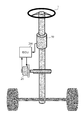
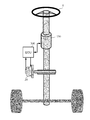
- the general configuration of the electric power steering apparatus will be described with reference to FIG. 6b is further connected to the steering wheels 8L and 8R via hub units 7a and 7b.
- a motor 20 that assists the steering force of the handle 1 is connected to the column shaft 2 via the reduction gear 3.
- the control unit (ECU) 30 that controls the electric power steering apparatus is supplied with electric power from the battery 13 and also receives an ignition key signal via the ignition key 11.
- the column shaft 2 includes a torque sensor 10 that detects the steering torque Th of the handle 1 and a steering angle that is a rotation angle of the handle 1 as a detection device or detector (hereinafter collectively referred to as “detection means”).
- a steering angle sensor 14 for detecting ⁇ is provided.
- the control unit 30 calculates the current command value of the assist command using an assist map or the like.
- the current supplied to the motor 20 is controlled by a voltage control value Vref obtained by compensating the current command value.
- the control unit 30 is connected to a CAN (Controller Area Network) 40 that transmits and receives various types of vehicle information, and the vehicle speed Vel can also be received from the CAN 40.
- the control unit 30 can be connected to a non-CAN 41 that exchanges communications, analog / digital signals, radio waves, and the like other than the CAN 40.
- the control unit 30 is mainly composed of a CPU (including MCU, MPU, etc.), and general functions executed by programs in the CPU are as shown in FIG.
- the function and operation of the control unit 30 will be described with reference to FIG. 2.
- the steering torque Th detected by the torque sensor 10 and the vehicle speed Vel detected by the vehicle speed sensor 12 (or from the CAN 40) are represented by the current command value Iref1.
- the current command value calculation unit 31 to be calculated is input.
- the current command value calculation unit 31 calculates a current command value Iref1, which is a control target value of the current supplied to the motor 20, using an assist map or the like based on the input steering torque Th and vehicle speed Vel.
- the current command value Iref1 is input to the current limiter 33 through the adder 32A, and the current command value Irefm whose maximum current is limited is input to the subtractor 32B, and the deviation I (Irefm) from the fed back motor current value Im.
- the inverter 37 uses a FET as a drive element, and is configured by a bridge circuit of the FET.
- a compensation signal CM from the compensation signal generator 34 is added to the adder 32A, and the compensation of the steering system system is performed by adding the compensation signal CM to improve the convergence and inertia characteristics.
- the compensation signal generation unit 34 adds the self-aligning torque (SAT) 343 and the inertia 342 by the addition unit 344, and further adds the convergence 341 to the addition result by the addition unit 345, and compensates the addition result of the addition unit 345.
- the signal CM is used.
- Patent Document 1 Japanese Patent Laid-Open No. 2013-253806
- Patent Document 2 Japanese Patent Laid-Open No. 2013-253806
- a sensor device including a plurality of sensor ICs having a plurality of detection units that detect corners and the like and output detection signals according to the detection results.
- the detection signal output from the sensor device is taken into the control device by a separate signal line from each detection unit, but may be taken in via one signal line provided for each sensor IC.
- Patent Document 2 an output magnetic detection element and a reference magnetic detection element are combined into one IC so that a failure of the magnetic sensor can be determined with a simple configuration while reducing the circuit scale and wiring.
- a detection apparatus in which a comparator that is housed in a package and further has a comparator for judging abnormality from detection values detected by the output magnetic detection element and the reference magnetic detection element is also housed in the same IC package. If the difference between the detection value (temporary detection value) output from the output magnetic detection element and the detection value (reference value) output from the reference magnetic detection element is equal to or less than the threshold value, the temporary detection value is output as an official detection value to the outside of the IC. is doing. By providing a plurality of IC packages, even if one breaks down, control can be continued using the official detection values output by other ICs.
- the sensors are usually connected to the control unit of the electric power steering apparatus via signal lines.
- the number of sensors to be multiplexed increases, and a device that suppresses the increase is proposed.
- Patent Document 3 in a redundant configuration in which each sensor is multiplexed so that control can be continued even if an abnormality occurs in the sensor, Sensors having different functions (for example, a torque sensor and a rotation angle sensor) are set as one set, and each set and the control unit are connected by a single serial bus.
- JP 2013-253806 A Japanese Patent No. 5688691 JP 2014-234101 A
- the sensor and the control unit are connected by a bus, so a CS (Chip Select) signal line for the control unit to identify (select) a communication partner is provided. , Connected for each sensor. Moreover, since the serial bus is shared by sensors having different functions, the bus occupation time is limited, and a sufficient detection cycle may not be obtained.
- CS Chip Select
- an object of the present invention is to use a redundant configuration including a plurality of sensor units including a plurality of detection units, and an abnormality has occurred in the sensor unit and the signal line.
- an object of the present invention is to provide a detection device that can accurately execute abnormality detection and function continuation in a control device such as an ECU and that can be easily manufactured, and an electric power steering device equipped with the detection device.
- Another object of the present invention is to suppress an excessive increase in the number of signal lines connecting the detector and the control unit and to depend on the configuration of the detector when mounting the detector having the redundant configuration as described above. It is an object of the present invention to provide an electric power steering apparatus that can acquire appropriate information without causing a failure and can continue operation even if an abnormality occurs in a detector.
- the present invention relates to a detection device that includes a plurality of sensor units including a plurality of detection units that have the same detection target and a detected state quantity, and that detects at least one of the state quantities by at least two sensor units.
- the above object is achieved by providing the communication unit that outputs the state quantity detected by the detection unit as a signal capable of error detection.
- the object of the present invention is that the communication unit collectively outputs the state quantity detected by each detection unit as one signal, or outputs the signal in synchronization with a control cycle, or
- the sensor unit generates the error-detectable signal by the SENT method, or includes at least four sensor units, detects steering torque by at least two sensor units, and at least two other This is achieved more effectively by detecting the steering angle with the sensor unit.
- the object of the present invention is to provide an error detection based on the error-detectable signal by inputting the error-detectable signal output from the communication unit to the electric power steering apparatus equipped with the detection device. And at least one of abnormality detection based on a plurality of detection values of the state quantity included in the error-detectable signal, and a controller that detects an abnormality of the detection device. . Furthermore, when the control unit detects an abnormality of the detection device, it continues operation using the normal state quantity or the control unit does not detect an abnormality of the detection device.
- Another object of the present invention is to provide a plurality of sensor units each including a plurality of detection units that have the same detection target and state quantity to be detected, and detect at least one state quantity using at least two sensor parts.
- a control unit that performs drive control of a motor based on the state quantity, and at least one signal line that connects the sensor unit and the control unit,
- the detection unit outputs the state quantity to the control unit via the same signal line, and the control unit estimates a state quantity at an arbitrary time from the state quantity and outputs it as an estimated state quantity
- This is achieved by including a quantity estimation unit and an abnormality detection unit that detects an abnormality of the detector by abnormality detection based on the state quantity and the estimated state quantity.
- the control unit outputs selection information used for selecting a detection unit that outputs the state quantity via the signal line, and the detection unit corresponding to the selection information includes the detection unit.
- the sensor unit includes a communication unit that outputs the state quantity as an error detectable signal, and the abnormality detecting unit is based on the error detectable signal.
- Abnormality detection is also performed to detect abnormality of the detector, or the communication unit generates the error detectable signal by the SENT method, or the state quantity estimation unit
- the control unit is configured to control the motor based on the normal state quantity.
- a plurality of the sensor units detect If the angle information is used to calculate the absolute angle of the angle information and an abnormality of the detector is detected, the normal angle information and the angle information and the absolute angle immediately before detecting the abnormality are used to detect an abnormality. This is achieved more effectively by calculating the absolute angle after detecting.
- the detection device of the present invention by using a communication method that includes a plurality of sensor units including a plurality of detection units and that can detect an error, it is possible to detect steering torque or the like with sufficient accuracy even after an abnormality occurs.
- the electric power steering apparatus equipped with the detection device can continue to operate.
- manufacture becomes easy, and when a signal line is put together into one, a failure rate and cost reduction can be aimed at.
- a detector including a plurality of sensor units including a plurality of detection units is mounted, and the plurality of detection units in the sensor unit output signals through the same signal line, and the detection unit
- the present invention has a redundant configuration including a plurality of sensor units each including a plurality of detection units, a detection device that detects a torque, a rotation angle, and the like, which are state quantities indicating a detection target state, and an electric power steering device equipped with the detection device
- the detection device outputs the detected state quantity (detection value) by a communication method capable of error detection.
- the present invention is an electric power steering apparatus (EPS) equipped with a detector that detects a torque, a rotation angle, and the like, which are state quantities indicating the state of a detection target, with the redundant configuration as described above.
- EPS electric power steering apparatus
- a control unit such as an ECU and a detector are connected by a bus, and a plurality of detection units in the sensor unit use the same bus (signal line) to input and output signals to and from the control unit.
- the detection unit that outputs the detected state quantity can be selected by selection information output from the control unit.
- the detection value output from the detection unit via the same signal line has a difference in acquisition timing, the state quantity at an arbitrary time from the past detection value (estimated state quantity; hereinafter referred to as “estimated value”) This reduces the influence of the variation (error) in the detected value due to the deviation.
- the detector can output the detected value by a communication method capable of detecting an error.
- the control unit can determine the occurrence of an abnormality in the sensor unit by comparing the detection value, etc., and the error detection function in the applied communication method can be used for the signal line through which the detection value flows. The occurrence of an abnormality can be determined.
- each sensor unit can function as a backup for other sensor units, and when there is a sensor unit that cannot output a correct detection value due to an abnormality, the electric power steering device The operation can be continued using the detection value of the sensor unit that outputs the correct detection value.
- FIG. 3 is a diagram showing an entire configuration example (first embodiment) including the electric power steering device, and the detection device detects a steering angle which is one of steering torque and angle information. That is, this detection device functions as a torque angle sensor having a plurality of functions of both the torque sensor 10 and the steering angle sensor 14 in the configuration shown in FIG.
- a steering torque and a steering angle output from the detection device (torque angle sensor) 50 of FIG. 3 are input to a control unit (ECU) 200 that is a control unit.
- the control unit 200 is based on the steering torque and the steering angle.
- the motor 20 that assists the steering force of the handle 1 is controlled.
- the detection device 50 includes a torque detector 60 that detects a steering torque and a steering angle detector 70 that detects a steering angle.
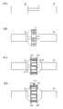
- FIG. 4 is a diagram for explaining a configuration example of the torque detector 60.
- the column shaft of the handle 1 is divided into an input shaft 2a on the handle side and an output shaft 2b on the steering gear side.
- the torque detector 60 includes a torsion bar 9 connecting the input shaft 2a and the output shaft 2b, a multipolar ring magnet 61 fixed to the input shaft 2a, a pair of sensor yokes 62a and 62b fixed to the output shaft 2b, and a pair. Magnet collecting yokes 63 a and 63 b and a torque sensor IC (sensor unit) 110. As shown in FIG.
- the torsion bar 9 is connected so that the center axis is coaxial with the input shaft 2a and the output shaft 2b, and twists when torque is applied in the circumferential direction of the column shaft.
- the multipolar ring magnet 61 has a cylindrical shape, and is fixed to the input shaft 2a so that the central axis is coaxial with the torsion bar 9, as shown in FIG. 4B. Are alternately magnetized in the circumferential direction.
- the sensor yokes 62 a and 62 b are soft magnetic annular bodies fixed to the output shaft 2 b so as to surround the multipolar ring magnet 61 in a pair.
- rectangular claws 621 a and 621 b are provided at equal intervals on the inner peripheral surface by the same number as the N poles and S poles of the multipolar ring magnet 61.
- the claws 621a of the sensor yoke 62a and the claws 621b of the sensor yoke 62b are alternately arranged in the circumferential direction so as to face the N pole and the S pole of the multipolar ring magnet 61. As shown in FIG.
- the magnetism collecting yokes 63a and 63b are arranged so as to sandwich the sensor yokes 62a and 62b, and a certain distance is provided between the magnetism collecting yokes 63a and 63b. Between these, the torque sensor IC 110 is disposed. Torque sensor IC 110 is connected to ECU 200 of the electric power steering device by a signal line. In this example, the magnetism collecting yokes 63a and 63b are configured to sandwich the sensor yokes 62a and 62b.
- the torque detector 60 having such a configuration will be described with reference to FIG.
- the multipolar ring magnet 61 is shown in a flat plate shape, and the scale of each part is changed.
- the multi-pole ring magnet 61 and the sensor yokes 62a and 62b are arranged so that the centers of the claws 621a and 621b of the sensor yokes 62a and 62b and the boundaries of the N-pole and S-pole of the multi-pole ring magnet 61 coincide. Place.
- the magnetic flux generated from the N pole of the multipolar ring magnet 61 flows into the S pole via the sensor yokes 62a and 62b, the magnetic flux flows in the torque sensor IC 110. No state.
- the torque sensor IC 110 When the driver steers and, for example, the steering torque is inputted to the maximum, that is, the maximum steering torque is applied to the input shaft 2a and the output shaft 2b, and the torsion bar 9 is maximally twisted (relative angle is maximum).
- the magnetic flux generated from the N pole reaches the torque sensor IC 110 from the magnetic collecting yoke 63b via the sensor yoke 62b.
- the magnetic flux returns to the S pole from the reverse side magnet collecting yoke 63a via the reverse side sensor yoke 62a.
- the torque sensor IC 110 outputs information corresponding to the detected magnetic flux density, that is, information proportional to the steering torque to the ECU 200 as a signal.
- steering torque information proportional to the steering torque
- each set is arranged at a certain interval in the circumferential direction of the sensor yokes 62a and 62b.
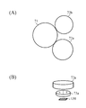
- FIG. 6 is a schematic diagram illustrating a configuration example of the rudder angle detection unit 70
- FIG. 6A is a plan view of the rudder angle detection unit 70
- FIG. 6B is a location of the slave gear 72 a of the rudder angle detection unit 70. It is the perspective view which extracted only.
- FIG. 6 only components necessary for explaining the operation of the steering angle detection unit 70 are illustrated, and the shape is also simplified.
- the rudder angle detector 70 includes a main gear 71 fixed to the output shaft 2b, slave gears 72a and 72b fitted to the master gear 71, and slave gears.
- Two-pole magnets 73a and 73b (not shown) fixed to 72a and 72b, respectively, and a steering angle sensor IC (sensor unit) fixed to a gear box (stationary system) corresponding to each of the slave gears 72a and 72b ) 130 and 140 (not shown).
- the sub-gears 72a and 72b have different reduction ratios, and rotation angle (steering angle) information output from the steering angle sensor IC paired with each sub-gear in the detection range (for example, ⁇ about 1.5 rotations by the steering wheel). Are always different from each other. Therefore, immediately after the ignition key is turned on, the rotation angle can be detected with an absolute angle of multiple rotations.
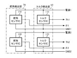
- the torque detection unit 60 of the detection device 50 includes two torque sensor ICs
- the steering angle detection unit 70 includes two steering angle sensor ICs.
- the configuration is shown in FIG.
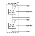
- the torque detector 60 includes torque sensor ICs 110 and 120, and outputs the detected steering torque as steering torques Th1 and Th2, respectively.
- the steering angle detection unit 70 includes steering angle sensors ICs 130 and 140, and outputs the detected rotation angles (steering angles) as steering angles ⁇ 1 and ⁇ 2, respectively.
- the torque sensor IC 110 and the rudder angle sensor IC 130 share the power source 1 and GND 1 (ground), and the torque sensor IC 120 and the rudder angle sensor IC 140 share the power source 2 and GND 2.
- the torque sensors IC 110 and 120 and the rudder angle sensors IC 130 and 140 have different basic functions when the torque sensor ICs 110 and 120 detect the strength of the magnetic flux density and the rudder angle sensors IC 130 and 140 detect the direction of the magnetic flux density.
- the correspondence to the signals output from each sensor IC is the same. Therefore, below, a structure and operation
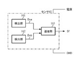
- Fig. 8 shows a configuration example of the sensor IC.
- the sensor IC includes detection units 101 and 102 and a communication unit 103.
- the detection units 101 and 102 output signals (detection values) Dva and Dvb corresponding to the detected state quantities, respectively.
- the communication unit 103 collectively outputs the detection values Dva and Dvb in one SENT frame Sf by a SENT (Single Edge Nibble Transmission) system which is one of signal protocols having an error detection function.
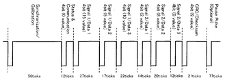
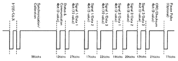
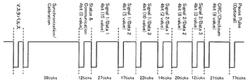
- SENT is a SAE (Society of Automotive Engineers) approved encoding method, and the outline of the frame structure used in SENT communication is shown in FIG.
- one frame includes a synchronization session, a status session, a data session, a CRC (Cyclic Redundancy Check) session, and a pause session.
- a synchronization session is used to synchronize between the transmitter and receiver.
- the status session is used to send an error code or the like.
- the data body to be transmitted / received is stored in the data session.
- CRC data is calculated by a CRC method using a polynomial (generator polynomial) and stored in a CRC session.
- the receiving side (ECU 200 in this embodiment) performs error detection using the same polynomial as that of the communication unit 103 based on the CRC data stored in the CRC session.
- the pause session is used to make the frame length constant.
- the detection values Dva and Dvb are distributed to the data sessions.
- the data sessions are data 1 to 3 (Data 1 to 3) of signal 1 (Signal 1) and data 1 to 3 of signal 2 (Signal 2). Since each data is composed of 4 bits, a total of 24 bits, that is, 12 bits of data are stored in the detection units 101 and 102 and output to the outside of the sensor IC.
- the detection values Dva and Dvb are the steering torque detection values Th1a and Th1b, and the SENT frame Sf is the steering torque Th1.
- the detection values Dva and Dvb are the steering torque detection values Th2a and Th2b, and the SENT frame Sf is the steering torque Th2.
- the detection values Dva and Dvb are the steering angle detection values ⁇ 1a and ⁇ 1b, and the SENT frame Sf is the steering angle ⁇ 1.
- the detection values Dva and Dvb are the steering angle detection values ⁇ 2a and ⁇ 2b, and the SENT frame Sf is the steering angle ⁇ 2.
- the symbol of the component of the torque sensor IC 110 is “ ⁇ 1”
- the symbol of the component of the torque sensor IC 120 is “ ⁇ 2”
- the symbol of the component of the steering angle sensor IC 130 is “ ⁇ 3”.
- the components of the rudder angle sensor IC 140 are distinguished from each other by adding “ ⁇ 4”.
- the magnetic flux density corresponding to the positional relationship between the multipolar ring magnet 61 and the sensor yokes 62a and 62b flows to the torque sensor ICs 110 and 120
- the magnetic flux density is converted into the detection units 101-1 and 102-1 in the torque sensor IC 110, and The four detection units 101-2 and 102-2 in the torque sensor IC 120 detect.
- the detected magnetic flux density is output to the communication unit 103-1 as the detected torque density by the detecting unit 101-1 as the detected steering torque Th1a and the detected unit 102-1 as the detected steering torque Th1b, respectively.
- the detection unit 102-2 outputs the detected torque value Th2a to the communication unit 103-2 as the detected steering torque value Th2b.
- the communication unit 103-1 stores the input steering torque detection values Th1a and Th1b in the SENT frame and outputs them as the steering torque Th1.
- the communication unit 103-2 stores the input steering torque detection values Th2a and Th2b in the SENT frame and outputs the steering torque Th2.
- the steering torques Th1 and Th2 are input to the ECU 200.
- the detection unit 101-3 and 102-3 in the rudder angle sensor IC 130 and four detection units 101-4 and 102-4 in the rudder angle sensor IC 140 are used.
- Two detectors detect the rotation angle (steering angle) of the dipole magnet.
- the detection unit 101-3 outputs the detected steering angle to the communication unit 103-3 as the steering angle detection value ⁇ 1a
- the detection unit 102-3 outputs the steering angle detection value ⁇ 1b to the communication unit 103-3.
- the detection unit 102-4 outputs the detected steering angle value ⁇ 2b to the communication unit 103-4.
- the communication unit 103-3 stores the input steering angle detection values ⁇ 1a and ⁇ 1b in the SENT frame and outputs them as the steering angle ⁇ 1.
- the communication unit 103-4 stores the input steering angle detection values ⁇ 2a and ⁇ 2b in the SENT frame and outputs them as the steering angle ⁇ 2.
- the steering angles ⁇ 1 and ⁇ 2 are input to the ECU 200.
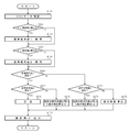
- the abnormality detection method and the detection value accuracy confirmation method in the ECU 200 in the electric power steering device will be described for each abnormality occurrence location.
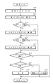
- step S12 When the difference dTh1 (absolute value) is larger than the threshold value FxT (step S12), it is determined that an abnormality has occurred in the torque sensor IC 110 (step S13), and when the difference dTh2 (absolute value) is larger than the threshold value FxT (step S14), It is determined that an abnormality has occurred in torque sensor IC 120 (step S15). When the magnitude of the difference does not exceed the threshold value FxT, it is determined that no abnormality has occurred, and the detected steering torque value is determined to have sufficient accuracy.
- step S16 when it is determined that an abnormality has occurred in the torque sensor IC 110 (step S16), if no abnormality has occurred in the torque sensor IC 120 (step S17), the steering torque detection values Th2a and Th2b have sufficient accuracy. Then, the processing is continued using them (step S18). If an abnormality has occurred in the torque sensor IC 120 (step S17), a warning is issued as an abnormality has occurred in both the torque sensor ICs 110 and 120 (step S19).
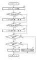
- the ECU 200 calculates an absolute angle from the steering angle ⁇ 1 output from the steering angle sensor IC 130 and the steering angle ⁇ 2 output from the steering angle sensor IC 140 (step S32).
- step S22 When the difference d ⁇ 1 (absolute value) is larger than the threshold value FxA (step S22), it is determined that an abnormality has occurred in the steering angle sensor IC 130 (step S23), and when the difference d ⁇ 2 (absolute value) is larger than the threshold value FxA (step S24). Then, it is determined that an abnormality has occurred in the rudder angle sensor IC 140 (step S25). When the magnitude of the difference does not exceed the threshold value FxA, it is determined that no abnormality has occurred and it is determined that the detected steering angle value has sufficient accuracy.
- the absolute angle is calculated based on the absolute angle information immediately before the abnormality occurs. That is, the ECU 200 holds the steering angles ⁇ 1 and ⁇ 2 input from the steering angle sensors IC 130 and 140 and the absolute angle obtained from them until the next steering angles ⁇ 1 and ⁇ 2 are input. If an abnormality occurs in the steering angle sensor IC 130 (step S26) and it is determined that no abnormality occurs in the steering angle IC 140 (step S27), the difference between the input steering angle ⁇ 2 and the immediately preceding steering angle ⁇ 2 is calculated.
- step S28 By adding to the immediately preceding absolute angle, the absolute angle after the occurrence of abnormality is calculated (step S28). If no abnormality has occurred in the steering angle sensor IC 130 (step S26) and it is determined that an abnormality has occurred in the steering angle IC 140 (step S29), the difference between the input steering angle ⁇ 1 and the immediately preceding steering angle ⁇ 1. Is added to the immediately preceding absolute angle to calculate the absolute angle after the occurrence of abnormality (step S30). If it is determined that an abnormality has occurred in both the steering angle sensors IC 130 and 140, a warning is issued (step S31).
- torque signal line a signal line for connecting the torque sensor IC and the ECU 200 to flow steering torque (signal)
- ECU200 confirms the presence or absence of abnormality using the value (CRC data) of the CRC session in the SENT frame of each of the steering torques Th1 and Th2.
- CRC data the value of the CRC session in the SENT frame of each of the steering torques Th1 and Th2.
- the CRC data is different from the expected value, so that the abnormality can be detected.
- the ECU 200 checks the CRC data of the steering torques Th1 and Th2 (step S40).
- step S41 the ECU 200 determines whether the torque sensor IC 110 and the ECU 200 When it is determined that an abnormality has occurred in the torque signal line (hereinafter referred to as “torque signal line 1”) (step S42), and the CRC data in the SENT frame of the steering torque Th2 is different from the expected value (step S43), the torque It is determined that an abnormality has occurred in the torque signal line between sensor IC 120 and ECU 200 (hereinafter referred to as “torque signal line 2”) (step S44). If the CRC data is as expected, it is determined that no abnormality has occurred in the torque signal line.
- step S45 when it is determined that an abnormality has occurred in the torque signal line 1 (step S45), if no abnormality has occurred in the torque signal line 2 (step S46), the process is continued using the steering torque Th2 (step S46). S47). If an abnormality has occurred in the torque signal line 2 (step S46), a warning is issued (step S48).
- steering angle signal line a signal line
- the ECU 200 calculates the absolute angle using the steering angle ⁇ 1 output from the steering angle sensor IC 130 and the steering angle ⁇ 2 output from the steering angle sensor IC 140 (step S61).
- the ECU 200 confirms the presence or absence of abnormality using the CR data in the SENT frames of the steering angles ⁇ 1 and ⁇ 2.
- the CRC data is different from the expected value, so that the abnormality can be detected.
- the ECU 200 confirms the CRC data of the steering angles ⁇ 1 and ⁇ 2 (step S50).
- step S51 the ECU 200 determines whether the steering angle sensor IC 130 and the ECU 200 Is determined that an abnormality has occurred in the steering angle signal line (hereinafter referred to as “steering angle signal line 1”) (step S52), and the CRC data in the SENT frame of the steering angle ⁇ 2 is different from the expected value (step S53). ), It is determined that an abnormality has occurred in the torque signal line (hereinafter referred to as “steering angle signal line 2”) between the steering angle sensor IC 140 and the ECU 200 (step S54). When the CRC data is as expected, it is determined that no abnormality has occurred in the steering angle signal line.
- the absolute angle is calculated based on the absolute angle information immediately before the abnormality occurs, as in the case where the abnormality occurs in the steering angle sensor IC. That is, when an abnormality occurs in the steering angle signal line 1 (step S55) and it is determined that no abnormality occurs in the steering angle signal line 2 (step S56), the input steering angle ⁇ 2 and the immediately preceding steering angle ⁇ 2 are detected. Is added to the immediately preceding absolute angle to calculate the absolute angle after the occurrence of abnormality (step S57).
- step S55 If no abnormality has occurred in the steering angle signal line 1 (step S55) and it is determined that an abnormality has occurred in the steering angle signal line 2 (step S58), the input steering angle ⁇ 1 and the immediately preceding steering angle The absolute angle after the occurrence of abnormality is calculated by adding the difference of ⁇ 1 to the immediately preceding absolute angle (step S59). If it is determined that both the steering angle signal line 1 and the steering angle signal line 2 are abnormal, a warning is issued (step S60). It is also possible to detect abnormalities due to external noise.
- power supply line 1 and “power supply line 2”, respectively
- ground lines the ground lines of GND1 and GND2
- the mismatch is confirmed by the comparison check of the steering torque detection values Th1a and Th1b or / and the comparison check of the steering angle detection values ⁇ 1a and ⁇ 1b, or the CRC data in the SENT frame of the steering torque Th1 or / and the steering angle ⁇ 1 is If it is different from the expected value, it can be determined that an abnormality has occurred in the feeder line 1 and / or the ground line 1. If there is no problem with the result of the comparison check for the detected steering torque value and the detected steering angle value and the CRC data check in the SENT frame of the steering torque and steering angle, the detected steering torque value and the detected steering angle value have sufficient accuracy.
- the absolute angle is calculated only from the detected steering angle values ⁇ 2a and ⁇ 2b, as in the case where an abnormality occurs in the steering angle sensor IC or the steering angle signal line, based on the absolute angle information immediately before the abnormality occurs. Calculate the absolute angle. When it is determined that an abnormality has occurred in the power supply line 2 and / or the ground line 2, the process is continued in the same manner.
- the detection device 50 includes two torque sensor ICs and two steering angle sensor ICs, each sensor IC includes two detection units, and the communication unit outputs the steering torque and the steering angle to the ECU 200 through SENT communication. Therefore, the ECU 200 can determine the occurrence of an abnormality in the sensor IC and the electric wire. If an abnormality occurs in one of the ECUs 200, the process can be continued by using the other.
- the SENT communication is asynchronous communication.
- the detected value is synchronized with the control cycle (control cycle) of the ECU 200 by using communication synchronized with the trigger pulse from the ECU 200. You may get Thereby, more stable control becomes possible. Further, any method other than SENT communication may be used as long as it is a signal protocol having an error detection function.
- the first embodiment includes the torque detection unit 60 and the steering angle detection unit 70, but may include only the torque detection unit 60 or only the steering angle detection unit 70.
- a configuration example (second embodiment) including only the torque detection unit 60 and a configuration example (third embodiment) including only the steering angle detection unit 70 are illustrated in FIGS. 15 and 16, respectively.
- the operation of the second embodiment shown in FIG. 15 is the same as the operation of the torque detector 60 in the first embodiment, and the operation of the third embodiment shown in FIG. 16 is the steering angle detection in the first embodiment.
- the operation is the same as that of the unit 70.
- each sensor IC in the first embodiment has one communication unit, a communication unit may be prepared for each detection unit, and two communication units may be provided.
- a configuration example (fourth embodiment) of a sensor IC including two communication units is shown in FIG.
- the detection value Dva output from the detection unit 101 is input to the communication unit 104
- the detection value Dvb output from the detection unit 102 is input to the communication unit 105.
- the communication unit 104 outputs the detection value Dva as a SENT frame Sf1 by the SENT method.
- the communication unit 105 also outputs the detection value Dvb as the SENT frame Sf2 by the SENT method.
- the detection device is used to detect the steering torque and the steering angle in the electric power steering device. You may use for detection of a rotation angle etc., You may apply to apparatuses other than an electric power steering apparatus.
- FIG. 18 is a diagram showing a configuration example of the fifth embodiment of the present invention
- the detector 150 has the configuration shown in FIG. 1 like the detection device 50 in the first embodiment shown in FIG. It functions as a torque angle sensor having a plurality of functions of both the torque sensor 10 and the steering angle sensor 14, and detects a steering angle which is one of steering torque and angle information.
- the steering torque and the steering angle output from the detector (torque angle sensor) 150 in FIG. 18 are input to a control unit (ECU) 300 that is a control unit, and the control unit 300 is similar to the ECU 200 in FIG. Based on the steering torque and the steering angle, the motor 20 that assists the steering force of the handle 1 is controlled.
- ECU control unit
- the detector 150 includes a torque detector 160 that detects a steering torque and a steering angle detector 170 that detects a steering angle.
- the torque detection unit 160 has the same configuration as the torque detection unit 60 in the first embodiment shown in FIG. 4, but a torque sensor IC 210 is arranged instead of the torque sensor IC 110, and the torque sensor IC 210 is connected to the ECU 300 and a signal. Connected by wire. Then, the torque detector 160 performs the same operation as the operation of the torque detector 60 in the first embodiment shown in FIG. At this time, the torque sensor IC 210 operates the torque sensor IC 110.
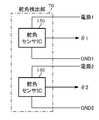
- the steering angle detection unit 170 has the same configuration as the steering angle detection unit 70 in the first embodiment whose schematic configuration example is shown in FIG. 6 and performs the same operation, but the steering angle sensor IC 130 and Steering angle sensors IC 230 and 240 are provided instead of 140, and the steering angle sensors IC 230 and 240 operate the steering angle sensors IC 130 and 140, respectively.
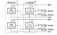
- the torque detection unit 160 of the detector 150 includes two torque sensor ICs, and the steering angle detection unit 170 includes two steering angle sensor ICs, and the configuration is shown in FIG.
- the torque detector 160 includes torque sensors ICs 210 and 220.
- the torque sensor IC 210 outputs the detected steering torques Thal and Thb1 via the signal line 11, and the torque sensor IC 220 outputs the detected steering torques Tha2 and Thb2. Output via the signal line 21.
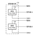
- the rudder angle detection unit 170 includes rudder angle sensors IC 230 and 240.
- the rudder angle sensor IC 230 outputs the detected rotation angles (steering angles) ⁇ a1 and ⁇ b1 via the signal line 12, and the rudder angle sensor IC 240 detects The steering angles ⁇ a2 and ⁇ b2 are output via the signal line 22.
- a master pulse (selection information) MP output from the ECU 300 is input to the torque sensor ICs 210 and 220 and the steering angle sensors IC 230 and 240 via signal lines connected to the sensor ICs. Further, the torque sensor IC 210 and the rudder angle sensor IC 230 share the power source 1 and GND (ground) 1, and the torque sensor IC 220 and the rudder angle sensor IC 240 share the power source 2 and GND 2.
- the torque sensors IC 210 and 220 detect the strength of the magnetic flux density
- the rudder angle sensors IC 230 and 240 have different basic functions when the direction of the magnetic flux density is detected. And the correspondence to the input / output signals for each sensor IC is the same. Therefore, below, a structure and operation
- FIG. 20 shows a configuration example of the sensor IC.
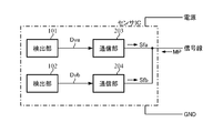
- the sensor IC includes detection units 101 and 102 and communication units 203 and 204.
- the detection units 101 and 102 output signals (detection values) Dva and Dvb corresponding to the detected state quantities, respectively, as in the case of the first embodiment.
- the communication unit 203 outputs the detected value Dva as a SENT frame Sfa to the ECU 300 via a signal line by the SENT method.
- the communication unit 204 outputs the detection value Dvb as the SENT frame Sfb to the ECU 300 via the signal line by the SENT method.
- the SENT frames Sfa and Sfb are output to the ECU 300 via the same signal line, and which is output is determined by the master pulse MP output from the ECU 300. That is, a unique master pulse is defined for each detection unit.
- the input master pulse MP is a master pulse for the detection unit connected to itself
- the communication unit 203 and 204 inputs a detection value from the detection unit.
- the detected value is output as a SENT frame.
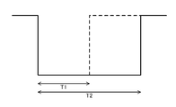
- the master pulse for example, a low level signal having a predetermined time length is used, and the time length is changed for each detection unit to obtain a unique master pulse. Therefore, the communication units 203 and 204 determine whether to output the SENT frame by checking the low level time of the master pulse.
- T1 master pulse master pulses having a low level time T1 and T2 as shown in FIG. 22
- T2 master pulse master pulses having a low level time T1 and T2 as shown in FIG. 22
- T1 master pulse master pulses having a low level time T1 and T2 as shown in FIG. 22
- a signal other than the low level signal may be used as the master pulse, and a numerical value or the like may be changed for each detection unit instead of the time length.
- the detection values Dva and Dvb are steering torque detection values, and the SENT frames Sfa and Sfb are steering torques Tha1 and Thb1, respectively.
- the detection values Dva and Dvb are steering torque detection values, and the SENT frames Sfa and Sfb are steering torques Tha2 and Thb2, respectively.
- the detection values Dva and Dvb are the steering angle detection values, and the SENT frames Sfa and Sfb are the steering angles ⁇ a1 and ⁇ b1, respectively.
- the detection values Dva and Dvb are the steering angle detection values, and the SENT frames Sfa and Sfb are the steering angles ⁇ a2 and ⁇ b2, respectively.
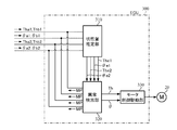
- FIG. 23 shows a configuration example of the ECU 300.
- the ECU 300 includes a state quantity estimation unit 310, an abnormality detection unit 320, and a motor control drive unit 330.
- the state quantity estimation unit 310 calculates an estimated value using the detected value in the SENT frame output from the detector 150 via the signal line. Specifically, the estimated value The1 of the steering torque from the steering torques Thal and Thb1, the estimated value of the steering angle ⁇ e1 from the steering angles ⁇ a1 and ⁇ b1, the estimated value The2 of the steering torque from the steering torques Tha2 and Thb2, and the steering angle ⁇ a2 And ⁇ b2 are used to calculate an estimated value ⁇ e2 of the steering angle.
- the calculation method will be described by taking calculation of the estimated value The1 from the steering torques Thal1 and Thb1 as an example.
- the estimated value is calculated using the steering torque detection values stored in the steering torques Tha1 and Thb1, respectively, but the steering torque detection value is also simply referred to as steering torque.
- the steering torques Thal and Thb1 are alternately acquired at a period L and are input to the state quantity estimation unit 310 via the signal line 11 as indicated by, for example, black circles in FIGS.
- the estimated value of the steering torque Tha1 at the time point t4 indicated by a white circle is calculated from the steering torque Tha1 (Tha1 (t1), Tha1 (t3)) at the time points t1 and t3 by linear approximation, that is, the following equation (1).
- the estimated value The1 is output (see FIG. 24A).
- the estimated value of the steering torque Tha1 at the time point t6 is calculated by linear approximation from the steering torques Tha1 (t3) and Tha1 (t5), and is output as the estimated value The1 (see FIG. 24A).
- the estimated value of the steering torque Thb1 is calculated from the steering torque Thb1 (t2) and Thb1 (t4) at the time point t5, and is estimated from the steering torque Thb1 (t4) and Thb1 (t6) at the time point t7.
- the values are calculated and output as estimated values The1 (see FIG. 24B). In this way, the estimated values of the steering torques Thal and Thb1 are alternately output as the estimated value The1.
- the estimated values ⁇ e1, The2, and ⁇ e2 are also calculated in the same manner as the estimated value The1. Note that the estimated value may be calculated not by linear approximation using the two detected values described above but by linear approximation or curve approximation using three or more detected values.
- the abnormality detection unit 320 detects abnormality based on the detection value in the SENT frame output from the detector 150 and the estimation value output from the state quantity estimation unit 310 (hereinafter referred to as “abnormality detection 1”);
- the abnormality of the detector 150 is detected by abnormality detection using the CRC session value (CRC data) in the SENT frame (hereinafter referred to as “abnormality detection 2”).
- CRC session value CRC session value
- abnormality detection 2 the magnitude (absolute value) of these two differences. Is greater than a predetermined threshold value, it is determined that an abnormality has occurred in the detector 150.
- the abnormality detection 2 when the CRC data is different from the expected value, it is determined that an abnormality has occurred.
- the detection value of the sensor IC is output to the motor control drive unit 330.
- the detected value of the torque sensor IC is output to the motor control drive unit 330 as the steering torque Th, and the detected value of the steering angle sensor IC is output as the steering angle ⁇ .
- one of the two sensor ICs in each of the torque detection unit 160 and the steering angle detection unit 170 is output.
- a value calculated using the detected value and the estimated value for example, an average value of both may be output.
- the abnormality detection unit 320 also outputs a master pulse MP to each sensor IC via a signal line.
- the T1 master pulse and the T2 master pulse shown in FIG. 22 are alternately output as the master pulse MP at a period L so that the SENT frames are alternately input from the two detection units 101 and 102 in each sensor IC.
- the motor control drive unit 330 includes, for example, a current command value calculation unit 31, an addition unit 32A, a compensation signal generation unit 34, a current limiting unit 33, a subtraction unit 32B, a PI control unit 35, a PWM in the configuration example illustrated in FIG.
- the control unit 36 and the inverter 37 are provided, and the motor 20 is driven and controlled based on the steering torque Th, the steering angle ⁇ , and the like output from the abnormality detection unit 320 by the same operation.
- the symbol of the component of the torque sensor IC 210 is “ ⁇ 1”
- the symbol of the component of the torque sensor IC 220 is “ ⁇ 2”
- the symbol of the component of the steering angle sensor IC 230 is “ ⁇ 3”.
- the reference numerals of the components of the rudder angle sensor IC 240 are distinguished from each other by adding “ ⁇ 4”.
- the torque detection unit 160 when a magnetic flux density corresponding to the positional relationship between the multipolar ring magnet 61 and the sensor yokes 62a and 62b flows to the torque sensor ICs 210 and 320, the magnetic flux density is detected by the detection unit 101- in the torque sensor IC 210.
- Four detection units 1 and 102-1 and detection units 101-2 and 102-2 in the torque sensor IC 220 detect. Then, the detected magnetic flux density is output to the communication units 203-1 and 204-1 as the steering torque detection value DThb1 and the detection unit 102-1 as the steering torque detection value DThb1, respectively.
- the communication unit 203-1 stores the input steering torque detection value DTha1 in the SENT frame, and outputs it as the steering torque Tha1 via the signal line 11, and the communication unit 204-1
- the input steering torque detection value DThb1 is stored in the SENT frame, and is output as the steering torque Thb1 via the signal line 11.
- the communication unit 203-2 stores the input steering torque detection value DTha2 in the SENT frame and outputs it as the steering torque Tha2 via the signal line 21, and the communication unit 204-2
- the input steering torque detection value DTha2 is stored in the SENT frame, and is output as the steering torque Thb2 via the signal line 21.
- the steering torques Tha1, Thb1, Tha2, and Thb2 are input to the ECU 300.
- the detection unit 101-3 outputs the detected steering angle to the communication units 203-3 and 204-3 as the steering angle detection value D ⁇ a1 and the detection unit 102-3 outputs the steering angle detection value D ⁇ b1, respectively.
- -4 is output to the communication units 203-4 and 204-4 as the steering angle detection value D ⁇ a2, and the detection unit 102-4 is output as the steering angle detection value D ⁇ b2.
- the communication unit 203-3 stores the input steering angle detection value D ⁇ a1 in the SENT frame, and outputs it as the steering angle ⁇ a1 via the signal line 12, and the communication unit 204-3
- the input steering angle detection value D ⁇ b1 is stored in the SENT frame, and is output via the signal line 12 as the steering angle ⁇ b1.
- the communication unit 203-4 stores the input steering angle detection value D ⁇ a2 in the SENT frame and outputs it as the steering angle ⁇ a2 via the signal line 22, and the communication unit 204-4
- the input steering angle detection value D ⁇ b2 is stored in the SENT frame and is output via the signal line 22 as the steering angle ⁇ b2.
- the steering angles ⁇ a1, ⁇ b1, ⁇ a2, and ⁇ b2 are input to the ECU 300.
- the abnormality detection unit 320 in the ECU 300 converts the master pulse MP into a T1 master pulse and outputs it to each sensor IC in the detector 150 via a signal line in order to obtain a detection value (step S101).
- the torque sensors IC 210 and 220 In response to the T1 master pulse, the torque sensors IC 210 and 220 output the steering torques Tha1 and Tha2, and the steering angle sensors IC230 and 240 output the steering angles ⁇ a1 and ⁇ a2, respectively.
- 320 is input (step S102).
- the state quantity estimation unit 310 calculates estimated values The1, The2, ⁇ e1, and ⁇ e2 according to Equation 1 from the input Thal, Thal2, ⁇ a1, and ⁇ a2 and their past values (step S103). Since these estimated values are used in the calculation of the next cycle, they are held until then (step S104).
- the abnormality detection unit 320 uses the input Tha1, Tha2, ⁇ a1 and ⁇ a2 and the estimated value calculated in the previous period and held in the state quantity estimation unit 310 to detect an abnormality detection method and the accuracy of the detection value, which will be described later.
- An abnormality is detected by the confirmation method (step S105), and when the steering torque Th and the steering angle ⁇ are obtained, they are output to the motor control drive unit 330.
- the motor control drive unit 330 controls the drive of the motor 20 based on the steering torque Th, the steering angle ⁇ , and the like (step S106).
- the abnormality detection unit 320 converts the master pulse MP into a T2 master pulse and outputs it to each sensor IC in the detector 150 via a signal line (step S107).
- the torque sensors IC 210 and 220 In response to the T2 master pulse, the torque sensors IC 210 and 220 output the steering torques Thb1 and Thb2, and the steering angle sensors IC 230 and 240 output the steering angles ⁇ b1 and ⁇ b2, respectively.
- 320 is input (step S108).
- the state quantity estimation unit 310 calculates estimated values The1, The2, Thee, and ⁇ e2 according to Equation 1 from the input Thb1, Thb2, ⁇ b1, and ⁇ b2 and their past values (step S109). Since these estimated values are used in the calculation of the next cycle, they are held until then (step S110).
- the abnormality detection unit 320 uses the input Thb1, Thb2, ⁇ b1, and ⁇ b2 and the estimated value held in the state quantity estimation unit 310 in step S104 to perform abnormality detection similar to step S105 (step S111), and the motor.
- the control drive unit 330 controls the drive of the motor 20 as in step S106 (step S112).
- step S101 to S112 is repeated until the operation is completed (step S113).
- the operation of the state quantity estimation unit 310 and the operation of the abnormality detection unit 320 may be executed in reverse or in parallel.
- the abnormality detection method and the accuracy confirmation method of the detection value in the abnormality detection unit 320 will be described for each abnormality occurrence location. Since the same operation is performed when the steering torques Tha1 and Tha2 and the steering angles ⁇ a1 and ⁇ a2 are input and when the steering torques Thb1 and Thb2 and the steering angles ⁇ b1 and ⁇ b2 are input, the steering torque is collectively referred to below. Let TH1 and TH2 and steering angles ⁇ _1 and ⁇ _2. The generic terms are also used for the detected steering torque value within the steering torque and the detected steering angle value within the steering angle.
- the abnormality detection unit 320 outputs the steering torque detection value DTH1 in the steering torque TH1 output from the torque sensor IC 210 as the steering torque Th.
- a predetermined threshold value FXT a predetermined threshold value
- step S122 When the difference ⁇ TH1 (absolute value) is larger than the threshold value FXT (step S122), it is determined that an abnormality has occurred in the torque sensor IC 210 (step S123), and when the difference ⁇ TH2 (absolute value) is larger than the threshold value FXT (step S124). It is determined that an abnormality has occurred in torque sensor IC 220 (step S125). If the magnitude of the difference does not exceed the threshold value FXT, it is determined that no abnormality has occurred, and it is determined that the detected steering torque value has sufficient accuracy.
- step S126 when it is determined that an abnormality has occurred in the torque sensor IC 210 (step S126), if no abnormality has occurred in the torque sensor IC 220 (step S127), the steering torque detection value DTH2 has sufficient accuracy.
- the steering torque detection value DTH2 is output as the steering torque Th (step S128). If an abnormality has occurred in the torque sensor IC 220 (step S127), a warning is issued as an abnormality has occurred in both the torque sensor ICs 210 and 220 (step S129).
- step S130 When it is determined that no abnormality has occurred in the torque sensor IC 210 (step S126), the steering torque detection value DTH1 is continuously output as the steering torque Th (step S130).
- the abnormality detection unit 320 is absolute from the steering angle detection value D ⁇ _1 in the steering angle ⁇ _1 output from the steering angle sensor IC230 and the steering angle detection value D ⁇ _2 in the steering angle ⁇ _2 output from the steering angle sensor IC240.
- the angle is calculated (step S142).
- step S132 When the difference ⁇ _1 (absolute value) is larger than the threshold value FXA (step S132), it is determined that an abnormality has occurred in the steering angle sensor IC 230 (step S133), and when the difference ⁇ _2 (absolute value) is larger than the threshold value FXA (step S134). It is determined that an abnormality has occurred in the rudder angle sensor IC 240 (step S135). When the magnitude of the difference does not exceed the threshold FXA, it is determined that no abnormality has occurred, and it is determined that the detected steering angle value has sufficient accuracy.
- the abnormality detection unit 320 holds the steering angles ⁇ _1 and ⁇ _2 input from the steering angle sensor ICs 230 and 240 and the absolute angle obtained from them until the next steering angles ⁇ _1 and ⁇ _2 are input.
- the steering angle detection value D ⁇ _2 within the input steering angle ⁇ _2 and the immediately preceding value are detected.
- the absolute angle after occurrence of abnormality is calculated by adding the difference of the detected steering angle D ⁇ _2 within the steering angle ⁇ _2 to the immediately preceding absolute angle (step S138). If no abnormality has occurred in the steering angle sensor IC 230 (step S136) and it is determined that an abnormality has occurred in the steering angle IC 240 (step S139), the steering angle detection value D ⁇ _1 within the input steering angle ⁇ _1 is determined.
- the absolute angle after occurrence of abnormality is calculated by adding the difference of the detected steering angle value D ⁇ _1 within the immediately preceding steering angle ⁇ _1 to the immediately preceding absolute angle (step S140). If it is determined that an abnormality has occurred in both the steering angle sensors IC 230 and 240, a warning is issued (step S141). The calculated absolute angle is output as the steering angle ⁇ (step S143).
- the abnormality detection unit 320 outputs the steering torque detection value DTH1 in the steering torque TH1 output from the torque sensor IC 210 as the steering torque Th.
- the abnormality detection unit 320 confirms the presence or absence of abnormality using CRC data in the SENT frames of the steering torques TH1 and TH2. When an abnormality occurs in the torque signal line, the CRC data is different from the expected value, so that the abnormality can be detected.
- the abnormality detection unit 320 confirms the CRC data of the steering torques TH1 and TH2 (step S151), and if the CRC data in the SENT frame of the steering torque TH1 is different from the expected value (step S152), the torque sensor IC 210 and the ECU 300 If the CRC signal in the SENT frame of the steering torque TH2 is different from the expected value (step S154), it is determined that an abnormality has occurred in the torque signal line (torque signal line 1) between the torque sensor IC 220 and the torque sensor IC 220. It is determined that an abnormality has occurred in the torque signal line (torque signal line 2) with ECU 300 (step S155). If the CRC data is as expected, it is determined that no abnormality has occurred in the torque signal line.
- step S156 when it is determined that an abnormality has occurred in the torque signal line 1 (step S156), and no abnormality has occurred in the torque signal line 2 (step S157), the detected steering torque value DTH2 in the steering torque TH2 is used as the steering torque. It outputs as Th (step S158). If an abnormality has occurred in the torque signal line 2 (step S157), a warning is issued (step S159). When it is determined that no abnormality has occurred in the torque signal line 1 (step S156), the steering torque detection value DTH1 is continuously output as the steering torque Th (step S160).
- the abnormality detection unit 320 calculates an absolute angle from the steering angle detection value D ⁇ _1 in the steering angle ⁇ _1 output from the steering angle sensor IC 230 and the steering angle detection value D ⁇ _2 in the steering angle ⁇ _2 output from the steering angle sensor IC 240. (Step S172).
- the abnormality detection unit 320 confirms the presence or absence of abnormality using the CR data in the SENT frames of the steering angles ⁇ _1 and ⁇ _2.
- the CRC data is different from the expected value, so that the abnormality can be detected.
- the abnormality detection unit 320 confirms the CRC data of the steering angles ⁇ _1 and ⁇ _2 (step S161).
- step S162 If the CRC data in the SENT frame of the steering angle ⁇ _1 is different from the expected value (step S162), the steering angle sensor IC 230 and the ECU 300 If the CRC data in the SENT frame of the steering angle ⁇ _2 is different from the expected value (step S164), it is determined that an abnormality has occurred in the steering angle signal line (steering angle signal line 1). It is determined that an abnormality has occurred in the torque signal line (steering angle signal line 2) between the angle sensor IC 240 and the ECU 300 (step S165). When the CRC data is as expected, it is determined that no abnormality has occurred in the steering angle signal line.
- the absolute angle is calculated based on the absolute angle information immediately before the abnormality occurs, as in the case where the abnormality occurs in the steering angle sensor IC. That is, when an abnormality occurs in the steering angle signal line 1 (step S166) and it is determined that no abnormality occurs in the steering angle signal line 2 (step S167), the detected steering angle value within the input steering angle ⁇ _2.
- the absolute angle after the occurrence of abnormality is calculated by adding the difference between D ⁇ _2 and the detected steering angle value D ⁇ _2 within the immediately preceding steering angle ⁇ _2 to the immediately preceding absolute angle (step S168). If no abnormality has occurred in the steering angle signal line 1 (step S166) and it is determined that an abnormality has occurred in the steering angle signal line 2 (step S169), the steering angle within the input steering angle ⁇ _1 is detected. By adding the difference between the value D ⁇ _1 and the detected steering angle value D ⁇ _1 within the immediately preceding steering angle ⁇ _1 to the immediately preceding absolute angle, the absolute angle after the occurrence of the abnormality is calculated (step S170). If it is determined that both the steering angle signal line 1 and the steering angle signal line 2 are abnormal, a warning is issued (step S171). The calculated absolute angle is output as the steering angle ⁇ (step S173). It is also possible to detect abnormalities due to external noise.
- the steering torque detection value DTH2 is output as the steering torque Th, and the steering angle detection value D ⁇ _2 and the absolute angle immediately before the abnormality is generated in the same manner as when the abnormality occurs in the steering angle sensor IC or the steering angle signal line.
- the absolute angle is calculated based on the information and output as the steering angle ⁇ .
- the detector 150 includes two torque sensor ICs and two steering angle sensor ICs, each sensor IC includes two detection units, and two more Since the communication unit outputs the steering torque and the steering angle to the ECU 300 by SENT communication, the ECU 300 can determine the occurrence of an abnormality in the sensor IC and the electric wire. Processing can continue.
- the communication unit may use a method other than SENT communication as long as it is a signal protocol having an error detection function.
- the detector 150 may be configured by only the torque detector 160 or only the steering angle detector 170.
- a configuration example (sixth embodiment) configured only from the torque detection unit 160 and a configuration example (seventh embodiment) configured only from the steering angle detection unit 170 are shown in FIGS. 30 and 31, respectively.
- each sensor IC in the fifth embodiment includes two communication units, but the two may be integrated to include only one communication unit.
- FIG. 32 shows a configuration example (eighth embodiment) of a sensor IC provided with only one communication unit.
- both the detection value Dva output from the detection unit 101 and the detection value Dvb output from the detection unit 102 are input to the communication unit 205.
- the communication unit 205 inputs the detection value Dva from the detection unit 101 when the master pulse MP is a T1 master pulse, and inputs the detection value Dvb from the detection unit 102 when the master pulse MP is a T2 master pulse.
- the detection value Dva is output as the SENT frame Sfa
- the detection value Dvb is output as the SENT frame Sfb.
- the communication unit may be deleted on the assumption that the abnormality of the detector 150 is detected only by the abnormality detection 1 without performing the abnormality detection 2. Thereby, further downsizing can be achieved.
- the detection unit determines the detection value output by the master pulse.
- each sensor IC is connected to the ECU 300 with a different signal line (the torque sensor IC 210 is the signal line 11, the torque sensor IC 220 is the signal line 21, the steering angle sensor IC 230 is the signal line 12,
- the steering angle sensor IC 240 may be connected to the signal line 22) and some or all of these signal lines may be connected together.
- signal lines can be reduced. In this case, it is necessary to change the master pulse not only between the detection units but also between sensor ICs using the same signal line.
- each of the torque detection unit and the steering angle detection unit includes two sensor ICs, but may include three or more sensor ICs.
- One detection unit is provided, but three or more detection units may be provided. Thereby, the backup function can be enhanced.
Landscapes
- Engineering & Computer Science (AREA)
- Physics & Mathematics (AREA)
- General Physics & Mathematics (AREA)
- Chemical & Material Sciences (AREA)
- Combustion & Propulsion (AREA)
- Transportation (AREA)
- Mechanical Engineering (AREA)
- Electromagnetism (AREA)
- Power Steering Mechanism (AREA)
- Steering Control In Accordance With Driving Conditions (AREA)
Abstract
Description
2 コラム軸(ステアリングシャフト、ハンドル軸)
9 トーションバー
10 トルクセンサ
12 車速センサ
13 バッテリ
14 舵角センサ
20 モータ
30、200、300 コントロールユニット(ECU)
31 電流指令値演算部
33 電流制限部
34 補償信号生成部
35 PI制御部
36 PWM制御部
37 インバータ
50 検出装置
60、160 トルク検出部
61 多極リング磁石
62a、62b センサヨーク
63a、63b 集磁ヨーク
70、170 舵角検出部
71 主ギア
72a、72b 従ギア
73a 二極磁石
101、102 検出部
103、104、105、203、204、205 通信部
110、120、210、220 トルクセンサIC
130、140、230、240 舵角センサIC
150 検出器
310 状態量推定部
320 異常検出部
330 モータ制御駆動部
Claims (16)
- 検出対象及び検出する状態量を同一とする複数の検出部を具備するセンサ部を複数備え、少なくとも1つの前記状態量を少なくとも2つの前記センサ部で検出する検出装置において、
前記センサ部が、前記検出部が検出する状態量を誤り検出可能な信号として出力する通信部を具備することを特徴とする検出装置。 - 前記通信部が、前記各検出部が検出する状態量を纏めて1つの信号として出力する請求項1に記載の検出装置。
- 制御周期に同期して前記信号を出力する請求項1又は2に記載の検出装置。
- 前記センサ部が、SENT方式によって前記誤り検出可能な信号を生成する請求項1乃至3のいずれかに記載の検出装置。
- 前記センサ部を少なくとも4つ備え、
少なくとも2つの前記センサ部で操舵トルクを検出し、
少なくとも2つの他の前記センサ部で操舵角を検出する請求項1乃至4のいずれかに記載の検出装置。 - 請求項1乃至5のいずれかに記載の検出装置を搭載し、
前記通信部から出力される前記誤り検出可能な信号を入力し、前記誤り検出可能な信号を基にした誤り検出と前記誤り検出可能な信号に含まれる前記状態量の複数の検出値を基にした異常検出の少なくとも1つを実行して、前記検出装置の異常を検出する制御部を備えることを特徴とする電動パワーステアリング装置。 - 前記制御部が、前記検出装置の異常を検出した場合、正常な前記状態量を使用して動作を継続する請求項6に記載の電動パワーステアリング装置。
- 前記制御部が、
前記検出装置の異常を検出していない場合、複数の前記センサ部がそれぞれ検出する複数の角度情報を用いて前記角度情報の絶対角度を算出し、
前記検出装置の異常を検出した場合、正常な前記角度情報並びに異常を検出する直前での前記角度情報及び前記絶対角度を用いて、異常を検出した後の前記絶対角度を算出する請求項6又は7に記載の電動パワーステアリング装置。 - 検出対象及び検出する状態量を同一とする複数の検出部を具備するセンサ部を複数備え、少なくとも1つの前記状態量を少なくとも2つの前記センサ部で検出する検出器を搭載した電動パワーステアリング装置において、
前記状態量に基づいてモータの駆動制御を行う制御部と、
前記センサ部及び前記制御部を接続する少なくとも1つの信号線とを備え、
前記センサ部内の複数の前記検出部は、同じ前記信号線を介して前記状態量を前記制御部に出力し、
前記制御部は、
前記状態量から任意の時間の状態量を推定し、推定状態量として出力する状態量推定部と、
前記状態量及び前記推定状態量を基にした異常検出により前記検出器の異常を検出する異常検出部とを具備することを特徴とする電動パワーステアリング装置。 - 前記制御部が、前記状態量を出力する検出部の選択に使用する選択情報を、前記信号線を介して出力し、
前記選択情報に対応する検出部が前記状態量を出力する請求項9に記載の電動パワーステアリング装置。 - 前記選択情報が所定のレベルの信号で、
前記検出部毎に異なる時間長の前記所定のレベルの信号を割り当て、
前記状態量を出力する検出部の選択を前記時間長に基づいて行う請求項10に記載の電動パワーステアリング装置。 - 前記センサ部が、前記状態量を誤り検出可能な信号として出力する通信部を具備し、
前記異常検出部が、前記誤り検出可能な信号に基づいた異常検出も行い、前記検出器の異常を検出する請求項9乃至11のいずれかに記載の電動パワーステアリング装置。 - 前記通信部が、SENT方式によって前記誤り検出可能な信号を生成する請求項12に記載の電動パワーステアリング装置。
- 前記状態量推定部が、過去の複数の前記状態量を用いて前記推定状態量を算出する請求項9乃至13のいずれかに記載の電動パワーステアリング装置。
- 前記異常検出部が前記検出器の異常を検出した場合、前記制御部は正常な前記状態量に基づいて前記モータの駆動制御を継続する請求項9乃至14のいずれかに記載の電動パワーステアリング装置。
- 前記状態量の1つとして角度情報があり、
前記制御部が、
前記検出器の異常を検出していない場合、複数の前記センサ部が検出する複数の前記角度情報を用いて前記角度情報の絶対角度を算出し、
前記検出器の異常を検出した場合、正常な前記角度情報並びに異常を検出する直前での前記角度情報及び前記絶対角度を用いて、異常を検出した後の前記絶対角度を算出する請求項9乃至15のいずれかに記載の電動パワーステアリング装置。
Priority Applications (4)
| Application Number | Priority Date | Filing Date | Title |
|---|---|---|---|
| US16/303,228 US10850769B2 (en) | 2016-07-05 | 2017-07-04 | Detecting apparatus and electric power steering apparatus |
| JP2018526390A JP6399260B2 (ja) | 2016-07-05 | 2017-07-04 | 電動パワーステアリング装置 |
| EP17824231.9A EP3444583A4 (en) | 2016-07-05 | 2017-07-04 | DETECTION DEVICE AND ELECTRIC POWER STEERING DEVICE |
| CN201780038252.5A CN109416293B (zh) | 2016-07-05 | 2017-07-04 | 检测装置以及电动助力转向装置 |
Applications Claiming Priority (4)
| Application Number | Priority Date | Filing Date | Title |
|---|---|---|---|
| JP2016-133649 | 2016-07-05 | ||
| JP2016133649 | 2016-07-05 | ||
| JP2016-217299 | 2016-11-07 | ||
| JP2016217299 | 2016-11-07 |
Publications (1)
| Publication Number | Publication Date |
|---|---|
| WO2018008628A1 true WO2018008628A1 (ja) | 2018-01-11 |
Family
ID=60912607
Family Applications (1)
| Application Number | Title | Priority Date | Filing Date |
|---|---|---|---|
| PCT/JP2017/024470 WO2018008628A1 (ja) | 2016-07-05 | 2017-07-04 | 検出装置及び電動パワーステアリング装置 |
Country Status (5)
| Country | Link |
|---|---|
| US (1) | US10850769B2 (ja) |
| EP (1) | EP3444583A4 (ja) |
| JP (1) | JP6399260B2 (ja) |
| CN (1) | CN109416293B (ja) |
| WO (1) | WO2018008628A1 (ja) |
Cited By (6)
| Publication number | Priority date | Publication date | Assignee | Title |
|---|---|---|---|---|
| DE102018129487A1 (de) * | 2018-11-22 | 2020-05-28 | Thyssenkrupp Ag | Winkelsensor mit mehrpoligem Magnet für eine Kraftfahrzeuglenkung |
| CN111976832A (zh) * | 2019-05-21 | 2020-11-24 | 上海汽车集团股份有限公司 | 一种方向盘转角数据的计算方法、装置及电子设备 |
| JP6816329B1 (ja) * | 2020-04-20 | 2021-01-20 | 株式会社ショーワ | 検出装置、ステアリング装置 |
| JPWO2021166648A1 (ja) * | 2020-02-18 | 2021-08-26 | ||
| JP2022505800A (ja) * | 2018-10-25 | 2022-01-14 | エーベーエム-パプスト ザンクト ゲオルゲン ゲーエムベーハー ウント コー.カーゲー | 実際の状態値を決定するための方法 |
| JP7492955B2 (ja) | 2018-10-25 | 2024-05-30 | エーベーエム-パプスト ザンクト ゲオルゲン ゲーエムベーハー ウント コー.カーゲー | 実際の状態値を決定するための方法 |
Families Citing this family (12)
| Publication number | Priority date | Publication date | Assignee | Title |
|---|---|---|---|---|
| US10800452B2 (en) * | 2016-03-04 | 2020-10-13 | Thyssenkrupp Ag | Ripple minimization by proper AS/TS magnet arrangement in electric power assisted steering apparatus |
| JP6559194B2 (ja) * | 2017-08-25 | 2019-08-14 | 本田技研工業株式会社 | 運転支援装置、運転支援方法、およびプログラム |
| US11926376B2 (en) * | 2018-02-02 | 2024-03-12 | Thyssenkrupp Presta Ag | Run-time stability monitoring of a steering angle sensor based on nonius principle |
| KR102066219B1 (ko) * | 2018-02-05 | 2020-01-14 | 주식회사 만도 | 리던던트 구조 기반의 차량 제어 장치 및 방법 |
| JP2020100274A (ja) * | 2018-12-21 | 2020-07-02 | 株式会社ジェイテクト | 操舵システム |
| US10843728B2 (en) * | 2019-01-31 | 2020-11-24 | StradVision, Inc. | Method and device for delivering steering intention of autonomous driving module or driver to steering apparatus of subject vehicle more accurately |
| JP7228405B2 (ja) * | 2019-02-21 | 2023-02-24 | 株式会社ジェイテクト | 制御回路及びモータ制御装置 |
| TWI770496B (zh) * | 2020-04-20 | 2022-07-11 | 達明機器人股份有限公司 | 機器人感測器的檢知方法 |
| CN111674458A (zh) * | 2020-06-11 | 2020-09-18 | 中国第一汽车股份有限公司 | 一种冗余机构线控转向装置和控制方法 |
| CN112265540A (zh) * | 2020-10-09 | 2021-01-26 | 宝能(广州)汽车研究院有限公司 | 双冗余转角信号控制方法、存储介质、车身稳定电子系统 |
| CN115609635A (zh) * | 2021-07-16 | 2023-01-17 | 达明机器人股份有限公司 | 机器人传感器的检测系统及方法 |
| US20240110777A1 (en) * | 2022-09-29 | 2024-04-04 | Allegro Microsystems, Llc | Sensor with estimated real-time parameter data |
Citations (2)
| Publication number | Priority date | Publication date | Assignee | Title |
|---|---|---|---|---|
| JP2015046770A (ja) * | 2013-08-28 | 2015-03-12 | 株式会社デンソー | 電子制御システム |
| WO2016042607A1 (ja) * | 2014-09-17 | 2016-03-24 | 日本精工株式会社 | 電動パワーステアリング装置 |
Family Cites Families (20)
| Publication number | Priority date | Publication date | Assignee | Title |
|---|---|---|---|---|
| JP3917080B2 (ja) * | 2002-03-08 | 2007-05-23 | 三菱電機株式会社 | モータ異常検出装置 |
| JP4007200B2 (ja) * | 2003-01-20 | 2007-11-14 | 株式会社ジェイテクト | 電動パワーステアリング装置 |
| JP4267976B2 (ja) | 2003-07-29 | 2009-05-27 | 本田技研工業株式会社 | 電動パワーステアリング装置 |
| JP4449488B2 (ja) | 2004-02-19 | 2010-04-14 | 日本精工株式会社 | 電動パワーステアリング装置の制御装置 |
| US7559405B2 (en) * | 2003-08-28 | 2009-07-14 | Nsk Ltd. | Controller for electric power steering device |
| JP5286357B2 (ja) * | 2008-05-28 | 2013-09-11 | 本田技研工業株式会社 | 電動ステアリング装置 |
| CN102762435B (zh) * | 2010-02-25 | 2015-09-30 | 本田技研工业株式会社 | 电动动力转向装置 |
| KR20120029084A (ko) * | 2010-09-16 | 2012-03-26 | 주식회사 만도 | 전동식 파워 스티어링 장치 |
| CN102582678B (zh) * | 2011-01-11 | 2013-11-06 | 联创汽车电子有限公司 | 一种具有软件集成监控功能的电动助力转向系统 |
| JP5942613B2 (ja) | 2012-06-05 | 2016-06-29 | 株式会社ジェイテクト | センサ装置 |
| JP5945741B2 (ja) | 2012-09-24 | 2016-07-05 | 日立オートモティブシステムズ株式会社 | 電動パワーステアリング装置 |
| CN102923189B (zh) * | 2012-10-11 | 2016-08-17 | 吉林大学 | 一种基于永磁同步电机的电动助力转向系统控制器及控制方法 |
| WO2014064856A1 (ja) * | 2012-10-23 | 2014-05-01 | 日本精工株式会社 | トルク検出装置、電動パワーステアリング装置及び車両 |
| JP5688691B2 (ja) * | 2012-11-15 | 2015-03-25 | 株式会社デンソー | 検出装置、及びトルクセンサ |
| JP6136595B2 (ja) * | 2013-06-04 | 2017-05-31 | 株式会社ジェイテクト | アクチュエータ制御装置 |
| JP6172678B2 (ja) * | 2014-04-30 | 2017-08-02 | インターナショナル・ビジネス・マシーンズ・コーポレーションInternational Business Machines Corporation | 検出装置、検出方法、およびプログラム |
| JP6001122B1 (ja) * | 2015-03-31 | 2016-10-05 | 本田技研工業株式会社 | 電動パワーステアリング装置 |
| JP6384401B2 (ja) * | 2015-05-20 | 2018-09-05 | 株式会社デンソー | センサ装置、および、これを用いた電動パワーステアリング装置 |
| JP6344307B2 (ja) * | 2015-05-20 | 2018-06-20 | 株式会社デンソー | センサ装置、および、これを用いた電動パワーステアリング装置 |
| JP6361589B2 (ja) * | 2015-06-11 | 2018-07-25 | 株式会社デンソー | 通信システム |
-
2017
- 2017-07-04 JP JP2018526390A patent/JP6399260B2/ja active Active
- 2017-07-04 WO PCT/JP2017/024470 patent/WO2018008628A1/ja active Application Filing
- 2017-07-04 EP EP17824231.9A patent/EP3444583A4/en not_active Withdrawn
- 2017-07-04 US US16/303,228 patent/US10850769B2/en active Active
- 2017-07-04 CN CN201780038252.5A patent/CN109416293B/zh active Active
Patent Citations (2)
| Publication number | Priority date | Publication date | Assignee | Title |
|---|---|---|---|---|
| JP2015046770A (ja) * | 2013-08-28 | 2015-03-12 | 株式会社デンソー | 電子制御システム |
| WO2016042607A1 (ja) * | 2014-09-17 | 2016-03-24 | 日本精工株式会社 | 電動パワーステアリング装置 |
Non-Patent Citations (1)
| Title |
|---|
| See also references of EP3444583A4 * |
Cited By (9)
| Publication number | Priority date | Publication date | Assignee | Title |
|---|---|---|---|---|
| JP2022505800A (ja) * | 2018-10-25 | 2022-01-14 | エーベーエム-パプスト ザンクト ゲオルゲン ゲーエムベーハー ウント コー.カーゲー | 実際の状態値を決定するための方法 |
| JP7492955B2 (ja) | 2018-10-25 | 2024-05-30 | エーベーエム-パプスト ザンクト ゲオルゲン ゲーエムベーハー ウント コー.カーゲー | 実際の状態値を決定するための方法 |
| DE102018129487A1 (de) * | 2018-11-22 | 2020-05-28 | Thyssenkrupp Ag | Winkelsensor mit mehrpoligem Magnet für eine Kraftfahrzeuglenkung |
| CN111976832A (zh) * | 2019-05-21 | 2020-11-24 | 上海汽车集团股份有限公司 | 一种方向盘转角数据的计算方法、装置及电子设备 |
| JPWO2021166648A1 (ja) * | 2020-02-18 | 2021-08-26 | ||
| WO2021166648A1 (ja) * | 2020-02-18 | 2021-08-26 | 日立Astemo株式会社 | 電子制御装置、電動パワーステアリング装置、及び電動パワーステアリング装置の制御装置 |
| JP7320122B2 (ja) | 2020-02-18 | 2023-08-02 | 日立Astemo株式会社 | 電子制御装置、電動パワーステアリング装置、及び電動パワーステアリング装置の制御装置 |
| JP6816329B1 (ja) * | 2020-04-20 | 2021-01-20 | 株式会社ショーワ | 検出装置、ステアリング装置 |
| WO2021214814A1 (ja) * | 2020-04-20 | 2021-10-28 | 日立Astemo株式会社 | 検出装置、ステアリング装置 |
Also Published As
| Publication number | Publication date |
|---|---|
| EP3444583A1 (en) | 2019-02-20 |
| US20200180689A1 (en) | 2020-06-11 |
| EP3444583A4 (en) | 2019-05-01 |
| CN109416293A (zh) | 2019-03-01 |
| US10850769B2 (en) | 2020-12-01 |
| JPWO2018008628A1 (ja) | 2018-09-27 |
| CN109416293B (zh) | 2021-08-03 |
| JP6399260B2 (ja) | 2018-10-03 |
Similar Documents
| Publication | Publication Date | Title |
|---|---|---|
| JP6399260B2 (ja) | 電動パワーステアリング装置 | |
| US10053141B2 (en) | Communication system | |
| US10717462B2 (en) | Sensor device and electric power steering device using same | |
| JP4676348B2 (ja) | 回転角検出装置とその異常検出装置及び電動パワーステアリング装置 | |
| US8579072B2 (en) | Electric power steering system and controller of the electric power steering system | |
| EP3192722B1 (en) | Electric power steering device | |
| US20160231142A1 (en) | Motor rotational angle detection device and electric power steering device using motor rotational angle detection device | |
| WO2013002251A1 (ja) | モータ駆動装置 | |
| US10077069B2 (en) | Sensor device and electric power steering device using same | |
| JP2015179070A (ja) | 回転角検出装置、および、これを用いた電動パワーステアリング装置 | |
| CN106254055B (zh) | 通信系统 | |
| JP6061117B2 (ja) | 電動パワーステアリング装置 | |
| US20160362129A1 (en) | Communication system | |
| CN105523077A (zh) | 旋转电机控制装置和使用其的电动助力转向装置 | |
| KR20190072833A (ko) | 두 개의 위성 기어를 이용하여 절대 조향각을 생성하는 장치 및 방법 | |
| JP6690523B2 (ja) | 検出装置 | |
| US10101396B2 (en) | Detection of current sensor malfunction | |
| WO2023013662A1 (ja) | 通信システム | |
| WO2019054089A1 (ja) | モータ駆動装置、モータ、および電動パワーステアリング装置 | |
| JP6212688B2 (ja) | 耐ノイズ性向上システム、および耐ノイズ性向上方法 | |
| KR20190033160A (ko) | 조향각 센서 및 토크 센서의 고장 여부에 따라 조향각을 송출하는 전동식 조향 장치 및 그 방법 | |
| WO2019054091A1 (ja) | モータ駆動装置、モータ、電動パワーステアリング装置、モータ駆動方法、および記録媒体 |
Legal Events
| Date | Code | Title | Description |
|---|---|---|---|
| ENP | Entry into the national phase |
Ref document number: 2018526390 Country of ref document: JP Kind code of ref document: A |
|
| WWE | Wipo information: entry into national phase |
Ref document number: 2017824231 Country of ref document: EP |
|
| ENP | Entry into the national phase |
Ref document number: 2017824231 Country of ref document: EP Effective date: 20181115 |
|
| 121 | Ep: the epo has been informed by wipo that ep was designated in this application |
Ref document number: 17824231 Country of ref document: EP Kind code of ref document: A1 |
|
| NENP | Non-entry into the national phase |
Ref country code: DE |