WO2018003852A1 - Dispositif de déviation optique et appareil lidar - Google Patents
Dispositif de déviation optique et appareil lidar Download PDFInfo
- Publication number
- WO2018003852A1 WO2018003852A1 PCT/JP2017/023747 JP2017023747W WO2018003852A1 WO 2018003852 A1 WO2018003852 A1 WO 2018003852A1 JP 2017023747 W JP2017023747 W JP 2017023747W WO 2018003852 A1 WO2018003852 A1 WO 2018003852A1
- Authority
- WO
- WIPO (PCT)
- Prior art keywords
- light
- wavelength
- laser light
- laser
- beam deflector
- Prior art date
Links
Images


Classifications
-
- G—PHYSICS
- G01—MEASURING; TESTING
- G01S—RADIO DIRECTION-FINDING; RADIO NAVIGATION; DETERMINING DISTANCE OR VELOCITY BY USE OF RADIO WAVES; LOCATING OR PRESENCE-DETECTING BY USE OF THE REFLECTION OR RERADIATION OF RADIO WAVES; ANALOGOUS ARRANGEMENTS USING OTHER WAVES
- G01S7/00—Details of systems according to groups G01S13/00, G01S15/00, G01S17/00
- G01S7/48—Details of systems according to groups G01S13/00, G01S15/00, G01S17/00 of systems according to group G01S17/00
- G01S7/481—Constructional features, e.g. arrangements of optical elements
- G01S7/4811—Constructional features, e.g. arrangements of optical elements common to transmitter and receiver
-
- G—PHYSICS
- G01—MEASURING; TESTING
- G01S—RADIO DIRECTION-FINDING; RADIO NAVIGATION; DETERMINING DISTANCE OR VELOCITY BY USE OF RADIO WAVES; LOCATING OR PRESENCE-DETECTING BY USE OF THE REFLECTION OR RERADIATION OF RADIO WAVES; ANALOGOUS ARRANGEMENTS USING OTHER WAVES
- G01S17/00—Systems using the reflection or reradiation of electromagnetic waves other than radio waves, e.g. lidar systems
- G01S17/88—Lidar systems specially adapted for specific applications
- G01S17/89—Lidar systems specially adapted for specific applications for mapping or imaging
-
- G—PHYSICS
- G01—MEASURING; TESTING
- G01S—RADIO DIRECTION-FINDING; RADIO NAVIGATION; DETERMINING DISTANCE OR VELOCITY BY USE OF RADIO WAVES; LOCATING OR PRESENCE-DETECTING BY USE OF THE REFLECTION OR RERADIATION OF RADIO WAVES; ANALOGOUS ARRANGEMENTS USING OTHER WAVES
- G01S7/00—Details of systems according to groups G01S13/00, G01S15/00, G01S17/00
- G01S7/48—Details of systems according to groups G01S13/00, G01S15/00, G01S17/00 of systems according to group G01S17/00
- G01S7/481—Constructional features, e.g. arrangements of optical elements
- G01S7/4814—Constructional features, e.g. arrangements of optical elements of transmitters alone
- G01S7/4815—Constructional features, e.g. arrangements of optical elements of transmitters alone using multiple transmitters
-
- G—PHYSICS
- G01—MEASURING; TESTING
- G01S—RADIO DIRECTION-FINDING; RADIO NAVIGATION; DETERMINING DISTANCE OR VELOCITY BY USE OF RADIO WAVES; LOCATING OR PRESENCE-DETECTING BY USE OF THE REFLECTION OR RERADIATION OF RADIO WAVES; ANALOGOUS ARRANGEMENTS USING OTHER WAVES
- G01S7/00—Details of systems according to groups G01S13/00, G01S15/00, G01S17/00
- G01S7/48—Details of systems according to groups G01S13/00, G01S15/00, G01S17/00 of systems according to group G01S17/00
- G01S7/481—Constructional features, e.g. arrangements of optical elements
- G01S7/4817—Constructional features, e.g. arrangements of optical elements relating to scanning
-
- G—PHYSICS
- G01—MEASURING; TESTING
- G01S—RADIO DIRECTION-FINDING; RADIO NAVIGATION; DETERMINING DISTANCE OR VELOCITY BY USE OF RADIO WAVES; LOCATING OR PRESENCE-DETECTING BY USE OF THE REFLECTION OR RERADIATION OF RADIO WAVES; ANALOGOUS ARRANGEMENTS USING OTHER WAVES
- G01S7/00—Details of systems according to groups G01S13/00, G01S15/00, G01S17/00
- G01S7/48—Details of systems according to groups G01S13/00, G01S15/00, G01S17/00 of systems according to group G01S17/00
- G01S7/481—Constructional features, e.g. arrangements of optical elements
- G01S7/4818—Constructional features, e.g. arrangements of optical elements using optical fibres
-
- G—PHYSICS
- G02—OPTICS
- G02B—OPTICAL ELEMENTS, SYSTEMS OR APPARATUS
- G02B5/00—Optical elements other than lenses
- G02B5/18—Diffraction gratings
-
- G—PHYSICS
- G02—OPTICS
- G02B—OPTICAL ELEMENTS, SYSTEMS OR APPARATUS
- G02B6/00—Light guides; Structural details of arrangements comprising light guides and other optical elements, e.g. couplings
- G02B6/10—Light guides; Structural details of arrangements comprising light guides and other optical elements, e.g. couplings of the optical waveguide type
- G02B6/12—Light guides; Structural details of arrangements comprising light guides and other optical elements, e.g. couplings of the optical waveguide type of the integrated circuit kind
- G02B6/122—Basic optical elements, e.g. light-guiding paths
- G02B6/1225—Basic optical elements, e.g. light-guiding paths comprising photonic band-gap structures or photonic lattices
-
- G—PHYSICS
- G02—OPTICS
- G02B—OPTICAL ELEMENTS, SYSTEMS OR APPARATUS
- G02B6/00—Light guides; Structural details of arrangements comprising light guides and other optical elements, e.g. couplings
- G02B6/10—Light guides; Structural details of arrangements comprising light guides and other optical elements, e.g. couplings of the optical waveguide type
- G02B6/12—Light guides; Structural details of arrangements comprising light guides and other optical elements, e.g. couplings of the optical waveguide type of the integrated circuit kind
- G02B6/122—Basic optical elements, e.g. light-guiding paths
- G02B6/124—Geodesic lenses or integrated gratings
-
- G—PHYSICS
- G02—OPTICS
- G02B—OPTICAL ELEMENTS, SYSTEMS OR APPARATUS
- G02B6/00—Light guides; Structural details of arrangements comprising light guides and other optical elements, e.g. couplings
- G02B6/24—Coupling light guides
- G02B6/26—Optical coupling means
- G02B6/28—Optical coupling means having data bus means, i.e. plural waveguides interconnected and providing an inherently bidirectional system by mixing and splitting signals
- G02B6/293—Optical coupling means having data bus means, i.e. plural waveguides interconnected and providing an inherently bidirectional system by mixing and splitting signals with wavelength selective means
- G02B6/29346—Optical coupling means having data bus means, i.e. plural waveguides interconnected and providing an inherently bidirectional system by mixing and splitting signals with wavelength selective means operating by wave or beam interference
- G02B6/2935—Mach-Zehnder configuration, i.e. comprising separate splitting and combining means
- G02B6/29352—Mach-Zehnder configuration, i.e. comprising separate splitting and combining means in a light guide
- G02B6/29355—Cascade arrangement of interferometers
-
- G—PHYSICS
- G02—OPTICS
- G02B—OPTICAL ELEMENTS, SYSTEMS OR APPARATUS
- G02B6/00—Light guides; Structural details of arrangements comprising light guides and other optical elements, e.g. couplings
- G02B6/24—Coupling light guides
- G02B6/26—Optical coupling means
- G02B6/34—Optical coupling means utilising prism or grating
-
- G—PHYSICS
- G02—OPTICS
- G02F—OPTICAL DEVICES OR ARRANGEMENTS FOR THE CONTROL OF LIGHT BY MODIFICATION OF THE OPTICAL PROPERTIES OF THE MEDIA OF THE ELEMENTS INVOLVED THEREIN; NON-LINEAR OPTICS; FREQUENCY-CHANGING OF LIGHT; OPTICAL LOGIC ELEMENTS; OPTICAL ANALOGUE/DIGITAL CONVERTERS
- G02F1/00—Devices or arrangements for the control of the intensity, colour, phase, polarisation or direction of light arriving from an independent light source, e.g. switching, gating or modulating; Non-linear optics
- G02F1/29—Devices or arrangements for the control of the intensity, colour, phase, polarisation or direction of light arriving from an independent light source, e.g. switching, gating or modulating; Non-linear optics for the control of the position or the direction of light beams, i.e. deflection
- G02F1/295—Analog deflection from or in an optical waveguide structure]
- G02F1/2955—Analog deflection from or in an optical waveguide structure] by controlled diffraction or phased-array beam steering
-
- G—PHYSICS
- G02—OPTICS
- G02B—OPTICAL ELEMENTS, SYSTEMS OR APPARATUS
- G02B6/00—Light guides; Structural details of arrangements comprising light guides and other optical elements, e.g. couplings
- G02B6/24—Coupling light guides
- G02B6/26—Optical coupling means
- G02B6/32—Optical coupling means having lens focusing means positioned between opposed fibre ends
Definitions
- the present invention relates to a light deflection device that controls the traveling direction of light, and a lidar device provided with the light deflection device.
- lidar equipment LiDER (Light Detection and Ranging, Laser Imaging Detection and Ranging)
- vehicle equipment a vehicle is used to measure the distance to a surrounding object as a two-dimensional image. Automatic driving and development of 3D maps are being conducted.
- Other applications of the lidar apparatus include laser printers and laser displays.
- the lidar device applies a light beam to an object, detects reflected light reflected back from the object, detects distance information from the time difference and frequency difference, and scans the light beam two-dimensionally. Get wide-angle three-dimensional information.
- Scanning of the light beam is performed using a light deflection device.
- a mechanical light deflection device with a rotating polygon mirror (polygon mirror) has been used.
- the light deflection device of this polygon mirror has the problem that it becomes unstable in an oscillating mobile such as a car and has a short life.
- small integrated mirrors using micromachine technology (MEMS technology) are also being put into practical use.
- MEMS technology micromachine technology
- Phased arrays and leaky waveguides have been studied as non-mechanical light deflection devices that solve the problems of these mechanical light deflection devices.
- a phased array uses light interference from multiple light emitters integrated on a substrate to form a light beam. By adjusting the phase of the individual radiators, beams can be formed in any direction.
- a leaky waveguide type light deflection device radiates light propagating in the waveguide upward or obliquely by a diffraction grating carved in the waveguide, a multilayer film formed above and below the waveguide, etc.
- the uniform radiation can form a sharp light beam, and the light beam can be scanned by changing the wavelength of light or the refractive index of the waveguide.
- the multilayer film is operated at a wavelength close to the condition (slow light condition) where the angular dispersion is large, the sensitivity to the wavelength and the refractive index is enhanced, and the beam scan angle can be increased.
- a waveguide with a diffraction grating is one in which light is gradually leaked from the waveguide by a weak diffraction grating to form a light beam, and the light beam can be scanned according to the wavelength and the waveguide refractive index.
- the lidar apparatus applies a light beam to an object and measures the distance based on the reflected light.
- time-of-flight (TOF) method of applying pulsed light to an object and measuring the delay time distance of the reflected pulse, frequency modulation of continuous light and applying to an object, distance from the difference frequency between reflected light and reference light
- FMCW Frequency Modulation Continuous Wave
- 150 m is considered as an example of a measurable distance.
- the distance between the rider device and the object is 300 m
- the time required for the light to reciprocate is 1 ⁇ s, considering the speed of light in the air.
- FIG. 12 is a diagram for explaining information acquisition for one frame of an image.
- FIG. 12A is a diagram for describing an example in which information acquisition of each pixel is sequentially performed.
- FIG. 12B is a diagram for describing an example in which information acquisition of each pixel is operated in parallel.
- Information on one frame is obtained by repeating the process for all the pixels in each of the blocks 100a to 100d.
- the frame rate is improved by operating in parallel for each block.
- the configuration in which a plurality of lidar devices are combined and the lidar devices are operated in parallel needs to be operated in parallel while synchronizing the operation time point of each block, so there is a problem that the system becomes large and complicated.
- the light deflection device and the lidar device according to the present invention solve the above-mentioned problems, and realize parallel operation with a simple configuration, and aim to avoid an increase in size or complexity of the system.
- the light deflection device in view of the dependence of the deflection angle on the wavelength and refractive index of light, individually determines each light of a plurality of wavelengths having different wavelengths depending on the wavelength and refractive index Simultaneously deflecting in parallel in the direction of each deflection angle realizes parallel operation of a plurality of light beams with a simple configuration.
- the plurality of deflected light beams can distinguish the individual light beams based on the difference in the wavelength of light or the deflection angle even in parallel operation at the same time.
- the light deflection device of the present invention comprises a beam deflector whose deflection angle has wavelength dependency and refractive index dependency.
- the beam deflector simultaneously deflects light of a plurality of wavelengths having different wavelengths in parallel in the direction of each deflection angle determined by each wavelength of the light and the refractive index of the beam deflector.
- the light deflecting device deflects the guided light at a plurality of respective deflection angles that are determined in response to changes in the wavelength of the light.
- the light deflection device deflects the guided light at each deflection angle determined corresponding to the wavelength and refractive index of the light.
- the wavelength of light is fixed, the light is deflected at a plurality of deflection angles determined corresponding to the change of the refractive index with reference to the deflection angle corresponding to the wavelength at that time.
- the beam deflector is composed of a single element that deflects light of each wavelength of plural wavelengths by one element, and is a complex in which plural elements that individually deflect light of each wavelength of plural wavelengths are arranged in an array It can be configured.
- a plurality of beam deflectors for deflecting the introduced light at a deflection angle determined corresponding to the wavelength of the light is provided, and the plurality of beam deflectors are arranged in parallel at each wavelength.
- the plurality of beam deflectors arranged in parallel introduce light of a plurality of wavelengths having different wavelengths to change the deflection angle, and introduce light of one wavelength or a plurality of wavelengths having different wavelengths and refracting By changing the rate, the deflection angle is changed to deflect the plurality of light beams into different deflection angles.
- the light deflection device of the present invention can constitute an emitter which deflects introduced light to form output light, and / or an injector which deflects light taken from the outside into incident light.
- the light taken in from the outside can be a reflected light obtained by reflecting the light emitted from the light emitter by the object.
- the deflection angle of the light deflection device corresponds to the emission angle at the emitter and to the incidence angle at the injector.
- An emitter according to the light deflection device of the present invention comprises a laser light source for emitting a plurality of laser beams of different wavelengths together with the beam deflector.
- the beam deflector emits laser light of a plurality of wavelengths emitted by the laser light source simultaneously in parallel in the direction of each deflection angle determined by the wavelength of each laser light and the refractive index of the beam deflector.
- the emitter may be configured to include a wavelength multiplexer / demultiplexer between the laser light source and the beam deflector.
- the wavelength multiplexer / demultiplexer wavelength-multiplexes laser light of a plurality of wavelengths of the laser light source and guides the obtained laser light of the plurality of wavelengths to a beam deflector.
- the injector according to the light deflection device of the present invention comprises a light detector for individually detecting the laser light.
- the beam deflector selectively and simultaneously inputs the laser beams whose deflection angles are determined by the wavelength of each laser beam and the refractive index of the beam deflector. Do.
- the photodetector detects the deflected light of the beam deflector.
- the injector may be configured to include a wavelength multiplexer / demultiplexer between the beam deflector and the light detector.
- the wavelength multiplexer / demultiplexer demultiplexes the incident laser light of a plurality of wavelengths and guides the obtained laser light of the plurality of wavelengths to a photodetector that detects each wavelength.
- the beam deflector of the present invention may be a surface grating known in the art or a leaky waveguide having a multilayer film structure or a surface grating.
- the lidar device of the present invention comprises the light deflection device of the present invention, a laser light source for emitting a plurality of laser beams having different wavelengths, and a light detection unit for individually detecting the laser beams.
- the light deflection device arrives from the outside from the outside and emits light of laser light of a plurality of wavelengths emitted by the laser light source simultaneously in parallel in the direction of each deflection angle determined by the wavelength of each laser light and the refractive index of the beam deflector.
- an injector which selectively and simultaneously makes the laser beams whose incident angles are the deflection angles are simultaneously arranged is constituted by the same element.
- the photodetector individually detects, in the injector, the laser light of each wavelength that is incident at the incident angle of the same deflection angle as the laser light emitted by the emitter. By matching the deflection angle of the emitter and the deflection angle of the injector, it is possible to detect the reflected light emitted from the emitter and reflected on the object.
- a wavelength multiplexer / demultiplexer can be provided between the laser light source and the beam deflector and / or between the beam deflector and the detector.
- the wavelength multiplexer / demultiplexer can perform wavelength multiplexing of laser light of a plurality of wavelengths emitted by the laser light source and / or wavelength division into laser light of each wavelength of the incident plurality of laser light of a plurality of wavelengths.
- the beam deflector provided in the lidar device can also be a surface diffraction grating, or a leaky waveguide having a multilayer film structure or a surface diffraction grating.
- the light deflection device and the lidar device of the present invention can realize parallel operation with a simple configuration, and can avoid the increase in size or complexity of the system.
- FIGS. 1 and 2 schematic configuration examples and operations of the light deflection device and the lidar device of the present invention will be described using FIGS. 1 and 2, and the respective embodiments of the light deflection device of the present invention will be described with reference to FIGS. 6 to describe the configuration of the lidar device of the present invention, FIGS. 7 and 8 to explain the light deflection device by the leak waveguide, and FIGS. 9 and 10 to explain the two-dimensional scanning of the light deflection device.
- An example of the wavelength multiplexer / demultiplexer will be described with reference to FIG.
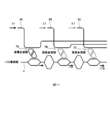
- FIG. 1 is a view for explaining an outline of a light deflection device according to the present invention.
- the light deflecting device simultaneously parallels each light of a plurality of wavelengths with different wavelengths based on the dependence of the deflection angle on the wavelength and refractive index of the light in the direction of each deflection angle individually determined by the wavelength and the refractive index.
- the plurality of light beams are operated in parallel.
- the plurality of deflected light beams can distinguish the individual light beams based on the difference in the light wavelength or the deflection angle.
- the light deflection device can be configured to include a beam deflector (not shown) whose deflection angle has wavelength dependency and refractive index dependency.
- FIG. 1 illustrates the wavelength dependence and refractive index dependence of the deflection angle of the light deflection device.
- 1 (a) to 1 (c) show deflection angles
- FIGS. 1 (d) to 1 (f) show emission angles when the light deflection device is used as an emitter
- FIGS. 1 (g) to 1 (i) Shows the incident angle when the light deflection device is used as an injector
- FIGS. 1 (j) to 1 (l) show the change of the deflection angle and the deflection angle. Note that the angles and magnitudes of changes shown in FIGS. 1 (a) to 1 (1) are schematically shown for the convenience of description and do not indicate an actual state.
- the light deflection device deflects light at different deflection angles based on wavelength and / or refractive index due to wavelength dependency and refractive index dependency of the deflection angle.
- FIG. 1A shows deflection angles ⁇ 1 to ⁇ p with respect to different wavelengths ⁇ 1 to ⁇ p at a fixed refractive index n.
- the light deflection device deflects the light of wavelength ⁇ 1 at a deflection angle ⁇ 1 corresponding to the refractive index n and the wavelength ⁇ 1, and the wavelength of the introduced light is ⁇ p.
- light of wavelength ⁇ p is deflected at a deflection angle ⁇ p corresponding to the refractive index n and the wavelength ⁇ p.
- FIG. 1 (b) shows deflection angles ⁇ a to ⁇ q for different refractive indexes na to nq at a fixed wavelength ⁇ .
- the light deflection device deflects the introduced light of wavelength ⁇ at a deflection angle ⁇ a corresponding to the wavelength ⁇ and the refractive index na when the refractive index is na, and when the refractive index is nq, The introduced light of wavelength ⁇ is deflected at a deflection angle ⁇ q corresponding to the wavelength ⁇ and the refractive index nq.
- FIG. 1C shows changes in the deflection angles ⁇ 1 to ⁇ p when the refractive index n is changed by ⁇ n at deflection angles ⁇ 1 to ⁇ p with respect to the wavelengths ⁇ 1 to ⁇ p different in refractive index n.
- the light deflection device deflects the light of wavelength ⁇ 1 at a deflection angle ⁇ 1 + ⁇ corresponding to the wavelength ⁇ 1 and the refractive index n + ⁇ n, and the wavelength of the introduced light is ⁇ p.
- light of wavelength ⁇ p is deflected at deflection angle ⁇ p + ⁇ corresponding to wavelength ⁇ p and refractive index n + ⁇ n.
- FIGS. 1 (d) to 1 (f) show the case of constituting a light emitter for deflecting the light introduced into the light deflection device and emitting the light to the outside of the light deflection device.
- FIG. 1 (d) shows the case where light beams are emitted with the deflection angles ⁇ 1 to ⁇ p as the emission angles with respect to different wavelengths ⁇ 1 to ⁇ p at a fixed refractive index n.
- the wavelength of the introduced light is ⁇ 1
- the light deflection device emits a light beam at an emission angle with a refractive index n and a deflection angle ⁇ 1 corresponding to the wavelength ⁇ 1
- the introduced light When the wavelength of ⁇ is ⁇ p, the light beam of wavelength ⁇ p is emitted with the deflection angle ⁇ p corresponding to the refractive index n and the wavelength ⁇ p as the emission angle. Since the light beams of the outgoing light are different in wavelength and outgoing angle, each outgoing light can be distinguished.
- FIG. 1 (e) shows the case where light beams are emitted with the deflection angles ⁇ a to ⁇ q for different refractive indexes na to nq as emission angles at a fixed wavelength ⁇ .
- the refractive index is na
- the light deflection device emits a light beam with the wavelength ⁇ and the deflection angle ⁇ a corresponding to the wavelength ⁇ and the refractive index na, and the refractive index is nq.
- the introduced light of wavelength ⁇ is emitted with an angle of deflection ⁇ q corresponding to the wavelength ⁇ and the refractive index nq as an output angle. Since the light beams of the outgoing light are different in outgoing angle, each outgoing light can be distinguished.
- FIG. 1 (f) shows the light beam with the change of the deflection angles .theta.1 to .theta.p when the refractive index n is changed by .DELTA.n at each deflection angle .theta.1 to .theta.p with respect to the wavelengths .lambda.1 to .lambda.p different in refractive index n. Shows the case of releasing.
- the light deflection device When the wavelength of introduced light is ⁇ 1, the light deflection device emits light of wavelength ⁇ 1 with a deflection angle ⁇ 1 + ⁇ corresponding to the wavelength ⁇ 1 and the refractive index n + ⁇ n, and the wavelength of the introduced light is When it is ⁇ p, the light of the wavelength ⁇ p is emitted as the outgoing angle at the deflection angle ⁇ p + ⁇ corresponding to the wavelength ⁇ p and the refractive index n + ⁇ n.
- the light beam of the outgoing light can expand the outgoing angle in the range of ⁇ with respect to the outgoing angle ⁇ determined by each wavelength.
- FIG. 1 (g) to FIG. 1 (i) show the case where an incident device for deflecting the light reaching the light deflection device and entering the light deflection device is configured.
- FIG. 1 (g) shows the case where, of the light beams reaching the light deflection device, light beams having incident angles with respect to the different wavelengths ⁇ 1 to ⁇ p at the fixed refractive index n are incident. It shows.
- the light deflection device When the wavelength of the light beam that has arrived is ⁇ 1, the light deflection device enters a light beam with an incident angle that matches the refractive index n and the deflection angle ⁇ 1 that corresponds to the wavelength ⁇ 1 in the light beam and reaches it.
- the wavelength of the light beam is ⁇ p, of the light beam, a light beam having an incident angle that coincides with the refractive index n and the deflection angle ⁇ p corresponding to the wavelength ⁇ p is incident. Since the light beams of the incident light are different in wavelength and incident angle, each incident light can be distinguished.
- FIG. 1 (h) shows the case where, among the light beams reaching the light deflection device, light beams having incident angles with the respective deflection angles ⁇ a to ⁇ q with respect to different refractive indexes na to nq are incident at the fixed wavelength ⁇ . Is shown.
- the light deflection device when the refractive index is na, the light beam is incident with the deflection angle ⁇ a corresponding to the wavelength ⁇ and the refractive index na among the light of the wavelength ⁇ of the reached light beam, and the refractive index is
- n nq
- the light beam is incident with the deflection angle ⁇ q corresponding to the wavelength ⁇ and the refractive index nq among the light of the wavelength ⁇ of the reached light beam as the incident angle.
- the light beams of the incident light can distinguish each incident light because the incident angles are different.
- FIG. 1 (i) shows that when the refractive index n is changed by ⁇ n at each of the deflection angles ⁇ 1 to ⁇ p with respect to the wavelengths ⁇ 1 to ⁇ p different in refractive index n, the light beam is changed with the change of the deflection angles ⁇ 1 to ⁇ p. Shows the case of incidence.
- the light deflection device receives a light beam having a wavelength of ⁇ 1 and a deflection angle ⁇ 1 + ⁇ corresponding to the refractive index n + ⁇ n from the light of wavelength ⁇ 1 and enters the light of wavelength ⁇ p
- a light beam having an angle of incidence as an incident angle is incident at a deflection angle ⁇ p + ⁇ corresponding to the wavelength ⁇ p and the refractive index n + ⁇ n.
- the light beam of incident light can expand the incident angle in the range of ⁇ with respect to the incident angle ⁇ determined at each wavelength.
- FIG. 1 (j) shows the outline of the dependence of the deflection angle ⁇ on the wavelength ⁇
- FIG. 1 (k) shows the outline of the dependence of the deflection angle ⁇ on the refractive index n
- FIG. 1 (l) shows The outline of the change ⁇ of the deflection angle ⁇ with respect to the change ⁇ n of the refractive index n is shown.
- FIG. 2 shows a schematic configuration of the rider apparatus 10.
- FIG. 2A shows a case where the rider device 10 is configured by a single light deflection device 1.
- the single light deflection device 1 simultaneously emits a plurality of light beams from one beam deflector at different emission angles, and simultaneously injects a plurality of light beams with the same beam deflector at an incidence angle of the same angle as the emission angle Do.
- a plurality of light beams can be emitted with the emission angles being differentiated by making the emission angles of the emission lights different, and by making the incident angles of each incident light be different, the incident angles can be differentiated with each other. It can be incident.
- FIG. 2B shows an array configuration in which a plurality of light deflection devices 1 are arranged in a line.
- the respective light deflection devices 1 constituting the lidar device 10 can obtain a plurality of simultaneous pixel data by operating the emission and the incidence in parallel with different deflection angles.
- this configuration by temporally changing the wavelength and the refractive index of each light deflection device 1, it is possible to acquire pixel data similar to the configuration in which a plurality of array structures are arranged.
- FIG. 2C shows the configuration of a two-dimensional arrangement in which a plurality of array structures shown in FIG. 2B are arrayed.
- the lidar device 10B in a two-dimensional arrangement can simultaneously emit and enter a plurality of light beams in a distinguishable manner by making the emission angle and the incidence angle of each light deflection device 1 different.
- FIGS. 3 and 4 show four forms of the light deflection device when configured as an emitter
- FIG. 5 illustrates three forms of the light deflection device when configured as an injector.
- an example of the light deflection device using three pieces of A to C for the beam deflector 2, the laser light source 3, and the waveguide 4 is shown, but the number of the light deflection devices is three The number is not limited to and may be any plural number.
- FIG. 3A shows a first embodiment in which the light deflection device is configured as a light emitter.
- the light deflection device 1A of the first embodiment introduces laser beams of different wavelengths ⁇ 1 to ⁇ 3 generated by the laser light sources 3A to 3C into the beam deflectors 2A to 2C through the waveguides 4A to 4C, respectively.
- a plurality of laser light sources generating respective wavelengths are constituted by the same integrated circuit, and a configuration using a plurality of laser light sources generating respective wavelengths or an external laser light source is used.
- the beam deflectors 2A to 2C may be configured such that a plurality of beam deflectors are formed on one substrate, and a plurality of beam deflectors formed on each substrate are disposed. The wavelength ⁇ generated by each laser light source is fixed.
- the beam deflector 2A emits the laser light of the laser light source 3A through the waveguide 4A as a radiation angle ⁇ 1 corresponding to the wavelength ⁇ 1 of the laser light.
- the beam deflectors 2B and 2C emit deflection angles ⁇ 2 and ⁇ 3 corresponding to the wavelengths ⁇ 2 and ⁇ 3 of the respective laser beams as emission angles.
- the refractive index n of each beam deflector is fixed.
- FIG. 3 (b) shows a second embodiment in which the light deflection device is configured as a light emitter.
- the light deflection device 1B of the second embodiment like the first embodiment, transmits the laser beams of different wavelengths ⁇ 1 to ⁇ 3 generated by the laser light sources 3A to 3C to the beam deflector 2A via the waveguides 4A to 4C. Introduce to ⁇ 2 C, and construct an emitter emitting at an emission angle corresponding to each wavelength.
- the light deflection device 1A of the first embodiment has a fixed wavelength ⁇ generated by each laser light source and the refractive index n of each beam deflector, whereas the light deflection device 1B of the second embodiment has a wavelength ⁇ And the refractive index n is variable.
- a plurality of laser light sources generating respective wavelengths are constituted by the same integrated circuit, and a configuration using a plurality of laser light sources generating respective wavelengths or an external laser light source is used.
- the beam deflectors 2A to 2C may be configured such that a plurality of beam deflectors are formed on one substrate, and a plurality of beam deflectors formed on each substrate are disposed.
- the beam deflector 2A emits the laser light of the laser light source 3A through the waveguide 4A as a radiation angle ⁇ 1 corresponding to the wavelength ⁇ 1 of the laser light. At this time, by changing the wavelength ⁇ 1 of the laser light generated by the laser light source 3A to ⁇ 1 + ⁇ , the emission angle of the light beam of the wavelength ⁇ 1 + ⁇ is changed and emitted from the beam deflector 2A.
- the emission angles of the light beams of the wavelengths ⁇ 2 + ⁇ and ⁇ 3 + ⁇ are changed and emitted.
- the light beam of a plurality of wavelengths is emitted by changing the wavelength ⁇ , and the radiation angle of the light beam is changed by changing the refractive index n by the width of ⁇ n. It can be scanned.
- FIG. 4A shows a third embodiment in which the light deflection device is configured as a light emitter.
- the third embodiment of the light deflection device 1C introduces laser beams of different wavelengths ⁇ 1 to ⁇ 3 generated by the laser light sources 3A to 3C into one beam deflector 2 through one bus waveguide 6,
- An emitter for emitting a plurality of light beams having different wavelengths at emission angles corresponding to the respective wavelengths is configured. Similar to the first embodiment, in the third embodiment, the wavelength ⁇ generated by each laser light source and the refractive index n of each beam deflector are fixed.
- a plurality of laser light sources generating respective wavelengths are constituted by the same integrated circuit, and a configuration using a plurality of laser light sources generating respective wavelengths or an external laser light source is used.
- the beam deflectors 2A to 2C are formed on a substrate.
- the wavelength ⁇ generated by each laser light source is fixed.
- the bus waveguide 6 is provided with a plurality of wavelength multiplexers / demultiplexers 7 A to 7 C, one end of which is connected to the beam deflector 2.
- the laser light sources 3A to 3C are connected to the wavelength multiplexers / demultiplexers 7A to 7C via waveguides 8A to 8C, and the laser light sources of the wavelengths ⁇ 1 to ⁇ 3 emitted by the respective laser light sources 3A to 3C are connected to the beam deflector 2.
- the beam deflector 2 introduces the laser light of the laser light source 3A through the waveguide 8A, the wavelength multiplexing / demultiplexing device 7A, and the bus waveguide 6, and sets the deflection angle ⁇ 1 corresponding to the wavelength ⁇ 1 of the laser light as the emission angle. Radiate. Also in the beam deflectors 2B and 2C, the laser light of the laser light sources 3B and 3C is introduced through the waveguides 8B and 8C, the wavelength multiplexing / demultiplexing devices 7B and 7C, and the bus waveguide 6, and the wavelength ⁇ 2 of the laser light It emits as deflection angles ⁇ 2 and ⁇ 3 corresponding to ⁇ 3.
- FIG. 4B shows a fourth embodiment in which the light deflection device is configured as a light emitter.
- the fourth embodiment of the light deflection device 1D is a single beam deflector for generating laser beams of different wavelengths ⁇ 1 to ⁇ 3 generated by the laser light sources 3A to 3C through the bus waveguide 6. 2 to construct an emitter emitting at an emission angle corresponding to each wavelength.
- the light deflecting device 1C of the third form has a fixed wavelength ⁇ generated by each laser light source and the refractive index n of each beam deflector, whereas the light deflecting device 1D of the fourth form has a wavelength ⁇ And the refractive index n is variable.
- a plurality of laser light sources generating respective wavelengths are constituted by the same integrated circuit, and a configuration using a plurality of laser light sources generating respective wavelengths or an external laser light source is used.
- the beam deflector 2 can be formed on one substrate.
- the beam deflector 2A introduces the laser light of the laser light source 3A through the waveguide 8A and the bus waveguide 6, and emits a deflection angle ⁇ 1 corresponding to the wavelength ⁇ 1 of the laser light as an emission angle.
- the wavelength ⁇ 1 of the laser light generated by the laser light source 3A to ⁇ 1 + ⁇
- the emission angle of the light beam of the wavelength ⁇ 1 + ⁇ is changed and emitted from the beam deflector 2.
- the beam deflector 2 applies laser light of the wavelengths ⁇ 2 and ⁇ 3 of the laser light sources 3B and 3C as well as the laser light of the wavelength ⁇ 1 + ⁇ . Change the emission angle of the light beam and emit it.
- the radiation angle of the light beam is changed by changing the refractive index n by the width of ⁇ n It can be scanned.
- the first to third embodiments in which the light deflection device is configured as an injector will be described below.
- the first form is a form in which the injector is constituted only by the beam deflector and the light detector.
- FIG. 5 (a) shows a first embodiment in which the light deflection device is configured as an injector.
- the light deflection device 1E of the first form of the injector includes a plurality of beam deflectors 2A to 2C, a plurality of light detectors 5A to 5C connected with the beam deflectors 2A to 2C, and waveguides 4A to 4C. It has 5C.
- each of the beam deflectors 2A to 2C is a laser having a deflection angle determined by the wavelength of each laser beam and the refractive index of the beam deflector among laser beams of plural wavelengths arriving from the outside.
- the light is selectively incident in parallel at the same time, and the incident laser light is individually detected by the light detector.
- the beam deflectors 2A to 2C may be configured such that a plurality of beam deflectors are formed on one substrate, and a plurality of beam deflectors formed on each substrate are disposed.
- the photodetectors 5A to 5C can be configured to use a plurality of photodetectors or to be configured by the same integrated circuit.
- the beam deflector 2A receives a light beam having a deflection angle ⁇ 1 as an incident angle among a plurality of arriving laser beams.
- the incident light beam is detected by the light detector 5A through the waveguide 4A.
- the beam deflectors 2B and 2C similarly to the beam deflector 2A, among the plurality of arriving laser beams, light beams having deflection angles ⁇ 2 and ⁇ 3 as incident angles are incident.
- the incident light beam is detected by the photodetectors 5B and 5C via the waveguides 4B and 4C.
- the refractive index n of each of the beam deflectors 2A to 2C is fixed.
- a light beam emitted from an emitter strikes an object and is reflected.
- the reflected light the reflected light reflected toward each beam deflector is detected by the light detector 5, converted into an electrical signal, and detected.
- the second form is a combination of a beam deflector and a light detector, and the beam deflector and the light detector can be integrated.
- FIG. 5 (b) shows a second embodiment in which the light deflection device is configured as an injector.
- the light deflection device 1F of the second form of the injector includes a plurality of beam deflectors 2A to 2C, and a plurality of photodetectors 5A connected to the beam deflectors 2A to 2C via waveguides 4A to 4C. It has 5C.
- waveguides 4A to 4C are branched, laser light sources 3A to 3C are connected to one branch end, and photodetectors 5A to 5C are connected to the other branch end.
- each of the beam deflectors 2A to 2C is a laser having a deflection angle determined by the wavelength of each laser beam and the refractive index of the beam deflector among laser beams of multiple wavelengths arriving from the outside.
- the light is selectively incident in parallel at the same time, and the incident laser light is individually detected by the light detector.
- the beam deflectors 2A to 2C may be configured such that a plurality of beam deflectors are formed on one substrate, and a plurality of beam deflectors formed on each substrate are disposed. Further, the laser light sources 3A to 3C are configured such that a plurality of laser light sources generating respective wavelengths are constituted by the same integrated circuit, and a plurality of laser light sources generating respective wavelengths are used or a configuration using an external laser light source can do.
- the beam deflector 2A emits a deflection angle ⁇ 1 corresponding to the wavelength ⁇ 1 of the laser light of the laser light source 3A to be connected as an emission angle, and sets the deflection angle ⁇ 1 as an incident angle among a plurality of arriving laser beams.
- a light beam is incident.
- the incident light beam is detected by the light detector 5A through the waveguide 4A.
- the deflection angles ⁇ 2 and ⁇ 3 corresponding to the wavelengths ⁇ 2 and ⁇ 3 of the laser light of the laser light sources 3B and 3C connected to the beam deflectors 2B and 2C, respectively.
- the plurality of laser beams that are emitted as an emission angle and arrive light beams having deflection angles ⁇ 2 and ⁇ 3 as incident angles are made incident.
- the incident light beam is detected by the photodetectors 5B and 5C via the waveguides 4B and 4C.
- the refractive index n of each of the beam deflectors 2A to 2C is fixed.
- the light beams emitted from the beam deflectors 2A to 2C strike the object and then reflect toward the respective beam deflectors. Since the reflected light follows the same optical path as the emitted light in the optical path between the beam deflectors 2A to 2C and the object and returns, the reflected light is reflected by maintaining the state of the beam deflectors 2A to 2C in the light emitting state. It can operate as an optical antenna that receives light at the same incident angle as the outgoing angle. By arranging the multiplexer / demultiplexer on the path between the laser light source and the object and detecting it by the light detector 5, it is possible to convert the reflected light into an electrical signal.
- the third mode is, as in the second mode, a combination of a beam deflector and a photodetector, and the beam deflector and the photodetector can be integrated.
- FIG. 5 (c) shows a third embodiment in which the light deflection device is configured as an injector.
- the light deflection device 1G of the third form of the injector includes one beam deflector 2, the beam deflector 2, the bus waveguide 6, the wavelength multiplexer / demultiplexer 7A to 7C, and the waveguides 8A to 8C.
- the wavelength multiplexing / demultiplexing devices 7A to 7C on the bus waveguide 6 connect the laser light sources 3A to 3C and the photodetectors 5A to 5C via the waveguides 8A to 8C, respectively. There is.
- the beam deflector 2 selects laser light having an incident angle determined by the wavelength of each laser light and the refractive index of the beam deflector among laser light of a plurality of wavelengths arriving from the outside At the same time, the laser beams are simultaneously incident in parallel, and the incident laser beams are individually detected by the photodetector.
- the beam deflector 2 is formed on a substrate. Further, the laser light sources 3A to 3C are configured such that a plurality of laser light sources generating respective wavelengths are constituted by the same integrated circuit, and a plurality of laser light sources generating respective wavelengths are used or a configuration using an external laser light source can do.
- the beam deflector 2 emits deflection angles ⁇ 1 to ⁇ 3 corresponding to the respective wavelengths ⁇ 1 to ⁇ 3 of the laser light of the plurality of laser light sources 3A to 3C connected via the bus waveguide 6 and reaches them while reaching them Among the plurality of laser beams, light beams having deflection angles ⁇ 1 to ⁇ 3 as incident angles are incident.
- the incident light beam is detected by each of the light detectors 5A to 5C through the bus waveguide 6, the wavelength multiplexing / demultiplexing devices 7A to 7C, and the waveguides 8A to 8C.
- the deflection angles ⁇ 2 and ⁇ 3 corresponding to the wavelengths ⁇ 2 and ⁇ 3 of the laser light of the laser light sources 3B and 3C connected to the beam deflectors 2B and 2C, respectively.
- the plurality of laser beams that are emitted as an emission angle and arrive light beams having deflection angles ⁇ 2 and ⁇ 3 as incident angles are made incident.
- the incident light beam is detected by the photodetectors 5B and 5C via the waveguides 4B and 4C.
- the refractive index n of each of the beam deflectors 2A to 2C is fixed.
- the light beam emitted from the beam deflector 2 is emitted at an emission angle corresponding to each wavelength, and after striking an object, reflects toward each beam deflector. Since the reflected light follows the same light path as the emitted light for each wavelength in the light path between the beam deflector 2 and the object, the reflected light keeps the state of the light deflector 2 in the light-emitted state.
- the light beam of the wavelength can be operated as an optical antenna that receives the reflected light at the same incident angle as the outgoing angle.
- FIG. 6 is a view for explaining the first to fifth embodiments of the rider apparatus.
- a first form of the rider apparatus is one in which the injector and the emitter are individually configured.
- FIG. 6A shows a first form of the rider apparatus.
- the lidar device 10A of the first embodiment includes an emitter composed of a laser light source 3, a waveguide 4 and a beam deflector 2, a beam deflector 2, a waveguide 4 and a photodetector 5 (photodiode). It comprises separately arranged injectors and arranged side by side.
- the emitter emits the light of the laser light source 3 from the beam deflector 2 to the outside, and the injector receives the reflected light that strikes the object and enters it, passes through a filter (not shown), and then passes through the branch path. It is guided to the light detection unit 4 and detected.
- the reflected light from the object spreads widely and diffuses, so that the angle of the light beam that can be received by the injector is slightly different from the radiation angle of the emitter even in the configuration where the injector is placed beside the emitter By setting, the reflected light can be received without directly entering the light emitted from the emitter.
- FIG. 6 (b) shows a second form of the rider apparatus.
- the lidar device 10A of the second embodiment has a configuration in which the waveguide 4 is branched and the light detection unit 5 (photodiode) is disposed at one end of the branch path.
- the beam deflector 2 causes the incident reflected light to pass through a filter (not shown), and then guides the reflected light to the light detection unit 5 via the branch path for detection.
- FIG. 6C shows a third embodiment.
- the optical switch 9 is inserted in the waveguide 4, and after the laser light of the laser light source 3 passes, the laser is switched to the light detection unit 5 (photodiode) side and reflected back. The light is guided to the light detection unit 5 (photodiode) with high efficiency.
- FIG. 6 (d) shows a fourth embodiment.
- a photodiode with a pn junction formed in a Si waveguide is subjected to strong reverse bias, it causes sub-band gap absorption via crystal defects, enabling detection of long-wavelength light that can not be originally detected .
- a photodiode having the above-described pn junction as the light detection unit 5 is inserted in the middle of the waveguide 4 and changed to a reverse bias after the laser light of the laser light source 3 passes. To detect the reflected light pulse.
- FIG. 6 (e) shows a fifth embodiment.
- the lidar device 10D of the fourth embodiment includes a pulse light source / light detection unit 11 which combines a laser light source and a light detection unit.
- the pulse light source / light detection unit 11 can operate as a photodiode by applying a reverse bias to a semiconductor laser to be a pulse light source. According to this configuration, after emitting the laser light, the pulse light source / light detection unit 11 applies a reverse bias to operate as a photodiode, and detects the reflected and returned laser light.
- the light from the laser source can be light pulses or continuous light.
- the lidar device can measure the distance by the TOF method when using the light pulse, and can measure the distance by the FMCW method when using the continuous light.
- the lidar device even if light of the same wavelength arrives from another direction, the incident angle is different, so the light does not follow the reverse order and is not coupled to the original waveguide, It does not enter the light detection unit (photodiode).
- an optical filter of a wavelength filter may be inserted in the waveguide 4.
- the optical filter is a filter that passes the wavelength of the laser light of the laser light source, and is preferably a variable wavelength filter that can change the passing wavelength in synchronization with the wavelength change when the wavelength of the laser light source is changed.
- the optical filter can remove noise components coupled to the optical waveguide in this manner. The removal of the noise component contributes to the improvement of the SN ratio when detecting the reflection signal of the lidar device.
- the beam deflector can be constituted by a leaky waveguide.
- the leaky waveguide is a diffraction grating carved into the waveguide, and a multilayer film formed above and below the waveguide.
- the light propagating in the waveguide is emitted upward or obliquely.
- the emitted light is uniform radiation, so a sharp light beam can be obtained. Since the radiation angle depends on the wavelength ⁇ of light and the refractive index n of the waveguide, the light can be deflected by changing the wavelength ⁇ and / or the refractive index n.
- the deflection angle can be increased by using a slow light structure as the waveguide.
- FIG. 7 shows a configuration example of the slow light structure in the leak waveguide type beam deflector.
- the waveguide 12 of the beam deflector 2 has the second refractive index medium arranged at a period a between the upper cladding 12b and the lower cladding 12c of the first refractive index medium.
- a slow light waveguide 12a is provided.
- the slow light waveguide 12a is formed with a first periodic structure in which a second refractive index medium is periodically arranged with a period a with respect to a refractive index cladding of the first refractive index medium.
- the first refractive index medium can be selected as a medium having a higher refractive index than the second refractive index medium.
- the slow light waveguide 12a propagates incident light incident from one end in a low group velocity slow light mode.
- the emitting portion 13 of the beam deflector 2 includes a surface diffraction grating 13a at a position adjacent to the upper cladding 12b.
- the surface diffraction grating 13a has a concavo-convex shape of a period ⁇ .
- the concavo-convex shape of the period ⁇ constitutes a second periodic structure of the period ⁇ ⁇ between the refractive index n of the refractive index medium constituting the surface diffraction grating 13a and the refractive index n out of the external medium such as air.
- the propagation constant ⁇ largely changes due to a slight change in propagation conditions such as the wavelength ⁇ of light and the refractive index n of the waveguide. Such light propagates while having the electromagnetic field spread (a leak component) around it.
- the emitting part 13 having a periodic structure (second periodic structure) formed with a small refractive index material or shallow etching or the like is provided at a distance such that the exudation component is slightly touched, a slow The light is coupled to it, scattered and diffracted, and emitted gradually upward and obliquely.
- the radiation occurs in a wide range along the waveguide traveling direction and is in phase. Therefore, when the light deflection device is viewed in the lateral direction along the propagation direction, the outgoing beam is a high quality sharp light beam.
- the propagation constant ⁇ of the waveguide 12 is changed, and the coupling condition with the second periodic structure of the emitting unit 13 is change.
- the outgoing angle ⁇ of the outgoing beam changes.
- the light of the surface diffraction grating is emitted not only in the upper oblique direction but also in the lower oblique direction. Since the structure of the light deflection device is top and bottom asymmetry, not all light of the same intensity is emitted, but also radiation in the lower oblique direction is generated.
- FIG. 7B shows radiation in the upper oblique direction as upward diffracted light and radiation in the lower oblique direction as downward diffracted light.
- the beam deflector 2 may be configured to include a reflector below the lower cladding 12c.
- FIGS. 7 (c) and 7 (d) show an example of the configuration provided with the reflection part.
- the configuration example shown in FIG. 7C shows the case where there is a high refractive index medium such as Si as a substrate of the structure.
- the radiation in the downward direction is reflected at the interface between the lower cladding 12 c and the high refractive index substrate 14 and returned obliquely upward.
- the thickness of the lower cladding 12c is optimized to cause interference between constructive interference of the reflected light and the light emitted in the upper diagonal direction in advance, the radiation in the upper diagonal direction can be intensified as a whole.
- the configuration example shown in FIG. 7D is a configuration in which a reflecting mirror 16 such as a metal reflecting mirror or a multilayer film reflecting mirror is inserted between the substrate 15 and the lower cladding 12c to further enhance the radiation in the upper diagonal direction. .
- the first refractive index medium is a high refractive index medium and the second refractive index medium is a low refractive index medium.
- a photonic crystal waveguide can be considered as an example of the first periodic structure that generates slow light.
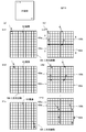
- 8 (a) to 8 (d) show an example of the first periodic structure by the photonic crystal waveguide, and FIGS. 8 (a) and 8 (b) show the one-dimensional photonic crystal waveguide, (C) shows a two-dimensional photonic crystal waveguide.
- the one-dimensional photonic crystal waveguide 12A shown in FIG. 8A is a configuration example in which circular holes are periodically arranged in a rectangular channel waveguide (such as Si thin wire) made of a high refractive index medium such as a semiconductor.
- the one-dimensional photonic crystal waveguide 12B of (b) is a configuration example in which rectangular channel waveguides of a high refractive index medium are periodically separated.
- the thickness of Si can be about 200 nm
- the width can be about 400 nm
- the diameter of the circular holes can be about 200 nm
- the period a about 400 nm, for ⁇ ⁇ 1550 nm.
- similar circular holes are two-dimensionally and periodically arranged, for example, in a triangular lattice array in a semiconductor (such as Si) slab having the same thickness, and It is the structure which removed the circular hole.
- a photonic band gap is generated in the vicinity of the Bragg wavelength, the group refractive index ng is increased, and the slow light is generated.
- n g > 100 occurs at the Bragg wavelength, but n g gradually decreases away from the Bragg wavelength .
- a two-dimensional photonic crystal waveguide can maintain large ng in a wider wavelength range.
- FIG. 8D is a perspective view showing a two-dimensional photonic crystal waveguide sandwiched by silica clads.
- a surface diffraction grating serving as a second periodic structure is formed on the surface of a two-dimensional photonic crystal waveguide in which silica cladding is formed.
- FIG. 9 shows a configuration example in which a two-dimensional beam sweep is performed by a combination of the array configuration of the slow light waveguide and the cylindrical lens.
- FIG. 9A a large number of slow light waveguides and diffraction gratings are arranged in parallel to constitute an array integration 23, and a cylindrical lens 24 is disposed in the emission direction of the emission side of the array integration 23.
- An optical amplifier and a phase adjuster 22 are connected to each slow light waveguide.
- a switching unit 21 is connected to the phase adjuster 22 and the light from the waveguide 20 is switched by the switching unit 21 to select a slow light waveguide to be incident, and the phase adjusted by the phase adjuster 22 is selected slow light It injects into a waveguide.
- the switching unit 21 can use an optical path switching optical switch or a wavelength demultiplexer.
- the incident light from the waveguide 20 is emitted from any of the slow light waveguides.
- the relative position of the outgoing beam to the cylindrical lens 24a changes, so the angle in the cross section of the outgoing beam coming out of the cylindrical lens 24a changes.
- the wavelength of the incident light is swept continuously over a wide range, and the waveguides are sequentially switched by sequentially switching the waveguides by the wavelength demultiplexer or by changing the wavelength of light in time series.
- the outgoing angle ⁇ of the outgoing beam can be changed according to the wavelength in each slow light waveguide.
- the waveguide is switched by a heater or an optical switch by a pn junction, and the emission angle ⁇ of the outgoing beam from the slow light waveguide is also changed by a heater or a pn junction.
- the slow light waveguide is switched by a wavelength demultiplexer and the outgoing beam is deflected by a heater or pn junction, and the slow light waveguide is switched by a heater or pn junction, and the outgoing beam is switched.
- the deflection may be performed by a wavelength splitter.
- FIG. 9A shows a configuration for selecting one of the waveguides in the waveguide array.
- the phase adjuster 22 is connected to the array integration 26 in which heaters and pn junctions having different lengths are provided in the slow light waveguides arranged in an array, The incident light from 20 is distributed to each waveguide through the power distributor 25, and each distributed light is adjusted in phase, and then enters the slow light waveguide.
- the array integration 26 constitutes a phased array in which light is incident on all the slow light waveguides and gradually different phase changes are given. This configuration achieves sharp beam radiation and changes in deflection angle due to phase changes. In this phased array configuration, an outgoing beam is formed by simultaneously emitting a plurality of light beams having different phases, and thus no cylindrical lens is required.
- the power distribution of the incident light in FIG. 10 (a) is strong when the central waveguide becomes strong and gradually weakens as the surrounding waveguide is reached, and the power distribution envelope is emitted by the Gaussian distribution.
- the quality of the outgoing beam formed later is particularly improved.
- a configuration used for an arrayed waveguide grating that is, light of an incident waveguide is once connected to a wide slab waveguide so that the light has a Gaussian distribution inside thereof. A free propagation may be made, and a desired number of arrayed waveguides may be connected to the end of the slab waveguide.
- FIG. 10 (b) shows an example of the cross-sectional structure of the array integration 26.
- the array integration 26 forms a phased array by providing heaters and pn junctions having different lengths of slow light waveguides arranged in an array in an array.
- FIG. 11 shows an example of a wavelength multiplexer / demultiplexer 7 using a triangular coupling micro ring resonator.
- the wavelength multiplexer / demultiplexer 7 a plurality of mutually coupled ring waveguides arranged in a narrow area of about 10 ⁇ m square form a box-shaped drop spectrum.
- the drop-shaped frequency band of this frequency characteristic as the pass band, a wavelength multiplexer / demultiplexer that combines light of a specific wavelength band with the bus waveguide is constructed.
- the drop spectrum to be appropriately wide, it is possible to secure a minute wavelength change ⁇ and secure stable multiplexing / demultiplexing characteristics.
- an optical modulator (not shown) can be provided on the waveguide 8 and used as a signal generation unit of a frequency modulation continuous wave (FMCW) type lidar device using a frequency optical modulator. can do.
- FMCW frequency modulation continuous wave
- the light deflection device and the lidar device (laser radar) of the present invention can be mounted on a car, drone, robot, etc., and can be mounted on a personal computer or smartphone to easily capture the surrounding environment, 3D scanner, monitoring system, light exchange
- the present invention can be applied to a space matrix optical switch for a data center.
Landscapes
- Physics & Mathematics (AREA)
- Engineering & Computer Science (AREA)
- General Physics & Mathematics (AREA)
- Optics & Photonics (AREA)
- Computer Networks & Wireless Communication (AREA)
- Radar, Positioning & Navigation (AREA)
- Remote Sensing (AREA)
- Nonlinear Science (AREA)
- Microelectronics & Electronic Packaging (AREA)
- Electromagnetism (AREA)
- Optical Integrated Circuits (AREA)
- Optical Radar Systems And Details Thereof (AREA)
- Semiconductor Lasers (AREA)
- Optical Couplings Of Light Guides (AREA)
- Optical Modulation, Optical Deflection, Nonlinear Optics, Optical Demodulation, Optical Logic Elements (AREA)
Abstract
La présente invention concerne un dispositif de déviation optique et un appareil lidar, dans lesquels des opérations parallèles sont mises en œuvre avec une configuration simple et une augmentation d'échelle ou de complexité du système est évitée. Compte tenu du fait que l'angle de déviation dépend de la longueur d'onde de la lumière et de l'indice de réfraction, un dispositif de déviation optique dévie simultanément en parallèle, dans la direction d'angles de déviation respectifs déterminés dans chaque cas par la longueur d'onde et l'indice de réfraction, la lumière respective d'une pluralité de longueurs d'onde amenées à avoir des longueurs d'onde différentes, de façon à mettre en œuvre une opération parallèle d'une pluralité de faisceaux lumineux avec une configuration simple. La lumière d'une pluralité de longueurs d'onde amenées à avoir des longueurs d'onde différentes peut être déviée simultanément en parallèle, en raison du fait qu'elle est déviée à des angles de déviation respectivement différents, déterminés par la longueur d'onde et l'indice de réfraction respectifs. La pluralité de faisceaux lumineux déviés, même en étant simultanément actionnés en parallèle, permettent la différenciation des différents faisceaux lumineux sur la base des différences de longueur d'onde et d'angle de déviation de la lumière.
Priority Applications (2)
| Application Number | Priority Date | Filing Date | Title |
|---|---|---|---|
| JP2018525207A JP6956964B2 (ja) | 2016-06-30 | 2017-06-28 | 光偏向デバイスおよびライダー装置 |
| US16/314,292 US11448729B2 (en) | 2016-06-30 | 2017-06-28 | Optical deflection device and LIDAR apparatus |
Applications Claiming Priority (2)
| Application Number | Priority Date | Filing Date | Title |
|---|---|---|---|
| JP2016130877 | 2016-06-30 | ||
| JP2016-130877 | 2016-06-30 |
Publications (1)
| Publication Number | Publication Date |
|---|---|
| WO2018003852A1 true WO2018003852A1 (fr) | 2018-01-04 |
Family
ID=60787046
Family Applications (1)
| Application Number | Title | Priority Date | Filing Date |
|---|---|---|---|
| PCT/JP2017/023747 WO2018003852A1 (fr) | 2016-06-30 | 2017-06-28 | Dispositif de déviation optique et appareil lidar |
Country Status (3)
| Country | Link |
|---|---|
| US (1) | US11448729B2 (fr) |
| JP (1) | JP6956964B2 (fr) |
| WO (1) | WO2018003852A1 (fr) |
Cited By (25)
| Publication number | Priority date | Publication date | Assignee | Title |
|---|---|---|---|---|
| US20190154805A1 (en) * | 2017-11-17 | 2019-05-23 | Topcon Corporation | Surveying Instrument And Surveying Instrument System |
| WO2019141646A1 (fr) * | 2018-01-16 | 2019-07-25 | Robert Bosch Gmbh | Système de détection optique, en particulier pour un système lidar dans un véhicule, et procédé pour le faire fonctionner |
| WO2019151058A1 (fr) * | 2018-02-05 | 2019-08-08 | 日本電気株式会社 | Dispositif de capteur |
| JP2019139116A (ja) * | 2018-02-14 | 2019-08-22 | 国立大学法人東京工業大学 | ビーム偏向デバイス |
| WO2019172166A1 (fr) * | 2018-03-05 | 2019-09-12 | パイオニア株式会社 | Dispositif de balayage et de mesure de distance |
| WO2019187777A1 (fr) * | 2018-03-27 | 2019-10-03 | パナソニックIpマネジメント株式会社 | Dispositif optique et système de détection optique |
| JP2019184649A (ja) * | 2018-04-02 | 2019-10-24 | 株式会社豊田中央研究所 | 光偏向素子 |
| WO2019202564A1 (fr) * | 2018-04-20 | 2019-10-24 | Srinivasan Tilak | Dispositif permettant la détermination de l'orientation d'un objet |
| WO2020059226A1 (fr) * | 2018-09-19 | 2020-03-26 | パナソニックIpマネジメント株式会社 | Dispositif optique et système de détection optique |
| WO2020106782A1 (fr) | 2018-11-21 | 2020-05-28 | Silc Technologies, Inc. | Collecteur optique pour applications lidar |
| EP3663792A1 (fr) * | 2018-12-03 | 2020-06-10 | Samsung Electronics Co., Ltd. | Dispositif de détection de lumière et de télémétrie et son procédé de commande |
| WO2020205240A1 (fr) * | 2019-04-04 | 2020-10-08 | Aeva, Inc. | Système lidar avec photodétecteur à guide d'ondes multimode |
| WO2021059757A1 (fr) * | 2019-09-27 | 2021-04-01 | パナソニックIpマネジメント株式会社 | Dispositif optique |
| CN112601999A (zh) * | 2018-08-10 | 2021-04-02 | 布莱克莫尔传感器和分析有限责任公司 | 用于利用准直射束扇形扫描相干lidar的方法和系统 |
| EP3764135A4 (fr) * | 2018-03-09 | 2021-04-07 | Panasonic Intellectual Property Management Co., Ltd. | Dispositif optique et système de détection optique |
| JP2021529310A (ja) * | 2018-06-25 | 2021-10-28 | シルク テクノロジーズ インコーポレイティッド | Lidar出力信号の方向を調整するための光学スイッチング |
| JPWO2022019143A1 (fr) * | 2020-07-20 | 2022-01-27 | ||
| JP2022517857A (ja) * | 2019-01-25 | 2022-03-10 | シルク テクノロジーズ インコーポレイティッド | Lidarシステムにおける出力信号の操縦 |
| WO2022124066A1 (fr) * | 2020-12-08 | 2022-06-16 | ソニーセミコンダクタソリューションズ株式会社 | Dispositif de télémétrie, procédé de télémétrie et programme |
| WO2023053499A1 (fr) * | 2021-09-30 | 2023-04-06 | ソニーセミコンダクタソリューションズ株式会社 | Dispositif de télémétrie et système de télémétrie |
| US11703598B2 (en) | 2019-11-18 | 2023-07-18 | Silc Technologies, Inc. | Steering of LIDAR output signals |
| DE112021006089T5 (de) | 2021-02-01 | 2023-09-28 | Ngk Insulators, Ltd. | Optisches Abtastelement |
| JP7425081B2 (ja) | 2019-03-20 | 2024-01-30 | アナログ フォトニクス エルエルシー | マルチスタティックコヒーレントLiDARの装置、方法及びシステム |
| DE112022002553T5 (de) | 2021-07-14 | 2024-04-11 | Ngk Insulators, Ltd. | Wellenleitervorrichtung, optische abtastvorrichtung und optische modulationsvorrichtung |
| JP7468148B2 (ja) | 2020-05-27 | 2024-04-16 | 株式会社デンソー | ビーム偏向システム |
Families Citing this family (12)
| Publication number | Priority date | Publication date | Assignee | Title |
|---|---|---|---|---|
| CN110678793B (zh) * | 2017-05-30 | 2020-11-03 | 国立大学法人横浜国立大学 | 光接收器阵列和光学雷达装置 |
| WO2019161388A1 (fr) * | 2018-02-16 | 2019-08-22 | Xiaotian Steve Yao | Détection optique basée sur une lumière multiplexée par répartition en longueur d'onde (wdm) à différentes longueurs d'onde dans des systèmes de détection de lumière et de télémétrie lidar |
| JP7130544B2 (ja) * | 2018-12-20 | 2022-09-05 | 三星電子株式会社 | 3次元情報算出装置、3次元計測装置、3次元情報算出方法及び3次元情報算出プログラム |
| US11543523B2 (en) * | 2018-12-28 | 2023-01-03 | Texas Instruments Incorporated | Multi frequency long range distance detection for amplitude modulated continuous wave time of flight cameras |
| US11467468B2 (en) * | 2019-05-28 | 2022-10-11 | The Board Of Trustees Of The Leland Stanford Junior University | Dispersion engineered phased array |
| DE102019124266A1 (de) * | 2019-09-10 | 2021-03-11 | Sick Ag | Optoelektronischer Sensor und Verfahren zum Erfassen von Objekten in einem Überwachungsbereich |
| US10788340B1 (en) * | 2019-09-12 | 2020-09-29 | Honeywell International Inc. | High resolution and high efficiency photonic air data detection |
| KR20210112596A (ko) * | 2020-03-05 | 2021-09-15 | 현대자동차주식회사 | 라이다용 레이저 송수신 모듈 |
| WO2021187119A1 (fr) * | 2020-03-19 | 2021-09-23 | 京セラ株式会社 | Dispositif de balayage et de mesure de distance |
| WO2022051453A1 (fr) | 2020-09-04 | 2022-03-10 | Analog Photonics LLC | Réseaux à commande de phase optiques bidimensionnels utilisant des circuits intégrés à couplage latéral |
| CN112490683B (zh) * | 2020-12-02 | 2021-09-07 | 南京大学 | 一种机械可调的电磁偏折器及其电磁波反射角度调控方法 |
| US20230069201A1 (en) * | 2021-09-02 | 2023-03-02 | Silc Technologies, Inc. | Use of multiple steering mechanisms in scanning |
Citations (3)
| Publication number | Priority date | Publication date | Assignee | Title |
|---|---|---|---|---|
| US20090136181A1 (en) * | 2006-05-11 | 2009-05-28 | Frank Vollmer | Methods, materials and devices for light manipulation with oriented molecular assemblies in micronscale photonic circuit elements with high-q or slow light |
| US20110028346A1 (en) * | 2009-08-03 | 2011-02-03 | Omega Optics, Inc. | Photonic crystal microarray device for label-free multiple analyte sensing, biosensing and diagnostic assay chips |
| WO2017126386A1 (fr) * | 2016-01-22 | 2017-07-27 | 国立大学法人横浜国立大学 | Dispositif de déflexion de lumière et appareil lidar |
Family Cites Families (1)
| Publication number | Priority date | Publication date | Assignee | Title |
|---|---|---|---|---|
| JP5662266B2 (ja) | 2011-07-01 | 2015-01-28 | 株式会社デンソー | 光偏向モジュール |
-
2017
- 2017-06-28 JP JP2018525207A patent/JP6956964B2/ja active Active
- 2017-06-28 US US16/314,292 patent/US11448729B2/en active Active
- 2017-06-28 WO PCT/JP2017/023747 patent/WO2018003852A1/fr active Application Filing
Patent Citations (3)
| Publication number | Priority date | Publication date | Assignee | Title |
|---|---|---|---|---|
| US20090136181A1 (en) * | 2006-05-11 | 2009-05-28 | Frank Vollmer | Methods, materials and devices for light manipulation with oriented molecular assemblies in micronscale photonic circuit elements with high-q or slow light |
| US20110028346A1 (en) * | 2009-08-03 | 2011-02-03 | Omega Optics, Inc. | Photonic crystal microarray device for label-free multiple analyte sensing, biosensing and diagnostic assay chips |
| WO2017126386A1 (fr) * | 2016-01-22 | 2017-07-27 | 国立大学法人横浜国立大学 | Dispositif de déflexion de lumière et appareil lidar |
Non-Patent Citations (1)
| Title |
|---|
| GU XIAODONG ET AL.: "Giant and high-resolution beam steering using slow-light waveguide amplifier", OPTICS EXPRESS, vol. 19, no. 23, 26 October 2011 (2011-10-26), pages 22675 - 22683, XP055451699 * |
Cited By (53)
| Publication number | Priority date | Publication date | Assignee | Title |
|---|---|---|---|---|
| US20190154805A1 (en) * | 2017-11-17 | 2019-05-23 | Topcon Corporation | Surveying Instrument And Surveying Instrument System |
| US11506759B2 (en) * | 2017-11-17 | 2022-11-22 | Topcon Corporation | Surveying instrument and surveying instrument system |
| WO2019141646A1 (fr) * | 2018-01-16 | 2019-07-25 | Robert Bosch Gmbh | Système de détection optique, en particulier pour un système lidar dans un véhicule, et procédé pour le faire fonctionner |
| WO2019151058A1 (fr) * | 2018-02-05 | 2019-08-08 | 日本電気株式会社 | Dispositif de capteur |
| JP2019135449A (ja) * | 2018-02-05 | 2019-08-15 | 日本電気株式会社 | センサ装置 |
| US11835742B2 (en) | 2018-02-05 | 2023-12-05 | Nec Corporation | Sensor device |
| US11506839B2 (en) | 2018-02-14 | 2022-11-22 | Tokyo Institute Of Technology | Beam deflection device |
| JP2019139116A (ja) * | 2018-02-14 | 2019-08-22 | 国立大学法人東京工業大学 | ビーム偏向デバイス |
| WO2019159918A1 (fr) * | 2018-02-14 | 2019-08-22 | 国立大学法人東京工業大学 | Dispositif de déviation de faisceau |
| JP7031856B2 (ja) | 2018-02-14 | 2022-03-08 | 国立大学法人東京工業大学 | ビーム偏向デバイス |
| WO2019172166A1 (fr) * | 2018-03-05 | 2019-09-12 | パイオニア株式会社 | Dispositif de balayage et de mesure de distance |
| EP3764135A4 (fr) * | 2018-03-09 | 2021-04-07 | Panasonic Intellectual Property Management Co., Ltd. | Dispositif optique et système de détection optique |
| WO2019187777A1 (fr) * | 2018-03-27 | 2019-10-03 | パナソニックIpマネジメント株式会社 | Dispositif optique et système de détection optique |
| JP2019184649A (ja) * | 2018-04-02 | 2019-10-24 | 株式会社豊田中央研究所 | 光偏向素子 |
| JP7077727B2 (ja) | 2018-04-02 | 2022-05-31 | 株式会社豊田中央研究所 | 光偏向素子 |
| US11287243B2 (en) | 2018-04-20 | 2022-03-29 | Tilak SRINIVASAN | Device for determining orientation of an object |
| WO2019202564A1 (fr) * | 2018-04-20 | 2019-10-24 | Srinivasan Tilak | Dispositif permettant la détermination de l'orientation d'un objet |
| JP7425000B2 (ja) | 2018-06-25 | 2024-01-30 | シルク テクノロジーズ インコーポレイティッド | Lidar出力信号の方向を調整するための光学スイッチング |
| JP2021529310A (ja) * | 2018-06-25 | 2021-10-28 | シルク テクノロジーズ インコーポレイティッド | Lidar出力信号の方向を調整するための光学スイッチング |
| CN112601999A (zh) * | 2018-08-10 | 2021-04-02 | 布莱克莫尔传感器和分析有限责任公司 | 用于利用准直射束扇形扫描相干lidar的方法和系统 |
| KR102532001B1 (ko) | 2018-08-10 | 2023-05-12 | 블랙모어 센서스 앤드 애널리틱스, 엘엘씨 | 콜리메이트된 빔들의 팬을 이용한 코히런트 lidar의 스캐닝을 위한 방법 및 시스템 |
| JP2021534383A (ja) * | 2018-08-10 | 2021-12-09 | ブラックモア センサーズ アンド アナリティクス エルエルシー | コリメートされたビームのファンを用いたコヒーレントlidarのスキャニングのための方法およびシステム |
| CN112601999B (zh) * | 2018-08-10 | 2022-11-08 | 布莱克莫尔传感器和分析有限责任公司 | 用于利用准直射束扇形扫描相干lidar的方法和系统 |
| KR20210042354A (ko) * | 2018-08-10 | 2021-04-19 | 블랙모어 센서스 앤드 애널리틱스, 엘엘씨 | 콜리메이트된 빔들의 팬을 이용한 코히런트 lidar의 스캐닝을 위한 방법 및 시스템 |
| JP7216188B2 (ja) | 2018-08-10 | 2023-01-31 | ブラックモア センサーズ アンド アナリティクス エルエルシー | コリメートされたビームのファンを用いたコヒーレントlidarのスキャニングのための方法およびシステム |
| JP7429928B2 (ja) | 2018-09-19 | 2024-02-09 | パナソニックIpマネジメント株式会社 | 光デバイスおよび光検出システム |
| JPWO2020059226A1 (ja) * | 2018-09-19 | 2021-08-30 | パナソニックIpマネジメント株式会社 | 光デバイスおよび光検出システム |
| WO2020059226A1 (fr) * | 2018-09-19 | 2020-03-26 | パナソニックIpマネジメント株式会社 | Dispositif optique et système de détection optique |
| JP7471292B2 (ja) | 2018-11-21 | 2024-04-19 | シルク テクノロジーズ インコーポレイティッド | ライダ用途のための光学マニホールド |
| WO2020106782A1 (fr) | 2018-11-21 | 2020-05-28 | Silc Technologies, Inc. | Collecteur optique pour applications lidar |
| US11782134B2 (en) | 2018-11-21 | 2023-10-10 | Silc Technologies, Inc. | Optical manifold for lidar applications |
| EP3884293A4 (fr) * | 2018-11-21 | 2022-08-03 | SiLC Technologies, Inc. | Collecteur optique pour applications lidar |
| JP2022509080A (ja) * | 2018-11-21 | 2022-01-20 | シルク テクノロジーズ インコーポレイティッド | ライダ用途のための光学マニホールド |
| CN111337933A (zh) * | 2018-12-03 | 2020-06-26 | 三星电子株式会社 | 光检测和测距设备及其驱动方法 |
| US11536806B2 (en) | 2018-12-03 | 2022-12-27 | Samsung Electronics Co., Ltd. | Light detection and ranging device and method of driving the same |
| EP3663792A1 (fr) * | 2018-12-03 | 2020-06-10 | Samsung Electronics Co., Ltd. | Dispositif de détection de lumière et de télémétrie et son procédé de commande |
| JP2022517857A (ja) * | 2019-01-25 | 2022-03-10 | シルク テクノロジーズ インコーポレイティッド | Lidarシステムにおける出力信号の操縦 |
| JP7425081B2 (ja) | 2019-03-20 | 2024-01-30 | アナログ フォトニクス エルエルシー | マルチスタティックコヒーレントLiDARの装置、方法及びシステム |
| JP2022527550A (ja) * | 2019-04-04 | 2022-06-02 | エヴァ インコーポレイテッド | マルチモード導波管光検出器を有するlidarシステム |
| WO2020205240A1 (fr) * | 2019-04-04 | 2020-10-08 | Aeva, Inc. | Système lidar avec photodétecteur à guide d'ondes multimode |
| JP7274602B2 (ja) | 2019-04-04 | 2023-05-16 | エヴァ インコーポレイテッド | マルチモード導波管光検出器を有するlidarシステム |
| US11754681B2 (en) | 2019-04-04 | 2023-09-12 | Aeva, Inc. | LIDAR system with a multi-mode waveguide photodetector |
| WO2021059757A1 (fr) * | 2019-09-27 | 2021-04-01 | パナソニックIpマネジメント株式会社 | Dispositif optique |
| US11703598B2 (en) | 2019-11-18 | 2023-07-18 | Silc Technologies, Inc. | Steering of LIDAR output signals |
| JP7468148B2 (ja) | 2020-05-27 | 2024-04-16 | 株式会社デンソー | ビーム偏向システム |
| JPWO2022019143A1 (fr) * | 2020-07-20 | 2022-01-27 | ||
| WO2022019143A1 (fr) * | 2020-07-20 | 2022-01-27 | 日本碍子株式会社 | Élément de balayage optique |
| JP7274608B2 (ja) | 2020-07-20 | 2023-05-16 | 日本碍子株式会社 | 光走査素子 |
| DE112021002832T5 (de) | 2020-07-20 | 2023-03-02 | Ngk Insulators, Ltd. | Optisches Abtastelement |
| WO2022124066A1 (fr) * | 2020-12-08 | 2022-06-16 | ソニーセミコンダクタソリューションズ株式会社 | Dispositif de télémétrie, procédé de télémétrie et programme |
| DE112021006089T5 (de) | 2021-02-01 | 2023-09-28 | Ngk Insulators, Ltd. | Optisches Abtastelement |
| DE112022002553T5 (de) | 2021-07-14 | 2024-04-11 | Ngk Insulators, Ltd. | Wellenleitervorrichtung, optische abtastvorrichtung und optische modulationsvorrichtung |
| WO2023053499A1 (fr) * | 2021-09-30 | 2023-04-06 | ソニーセミコンダクタソリューションズ株式会社 | Dispositif de télémétrie et système de télémétrie |
Also Published As
| Publication number | Publication date |
|---|---|
| US11448729B2 (en) | 2022-09-20 |
| US20190204419A1 (en) | 2019-07-04 |
| JPWO2018003852A1 (ja) | 2019-04-18 |
| JP6956964B2 (ja) | 2021-11-02 |
Similar Documents
| Publication | Publication Date | Title |
|---|---|---|
| WO2018003852A1 (fr) | Dispositif de déviation optique et appareil lidar | |
| TWI780120B (zh) | 模組式三維光學感測系統(二) | |
| US11079541B2 (en) | Optical deflection device and LIDAR apparatus | |
| US11960006B2 (en) | Wavelength division multiplexed LiDAR | |
| JP7425000B2 (ja) | Lidar出力信号の方向を調整するための光学スイッチング | |
| JP6732225B2 (ja) | ビーム偏向デバイス | |
| US11971589B2 (en) | Photonic beam steering and applications for optical communications | |
| US20220050187A1 (en) | Scan-less 3d optical sensing devices and associated lidar based on stacking of integrated photonic chips, wavelength division demultiplexing and position-to-angle conversion of a lens | |
| JP2019095218A (ja) | 測距センサ | |
| Alshamrani et al. | A non-mechanical multi-wavelength integrated photonic beam steering system | |
| JP2018180116A (ja) | 光偏向デバイス、及びライダー装置 | |
| JP2006323175A (ja) | 光出力方法及び光出力装置 | |
| CN118020000A (en) | Switch type pixel array LiDAR sensor and optoelectronic integrated circuit |
Legal Events
| Date | Code | Title | Description |
|---|---|---|---|
| 121 | Ep: the epo has been informed by wipo that ep was designated in this application |
Ref document number: 17820206 Country of ref document: EP Kind code of ref document: A1 |
|
| ENP | Entry into the national phase |
Ref document number: 2018525207 Country of ref document: JP Kind code of ref document: A |
|
| NENP | Non-entry into the national phase |
Ref country code: DE |
|
| 122 | Ep: pct application non-entry in european phase |
Ref document number: 17820206 Country of ref document: EP Kind code of ref document: A1 |