WO2017221732A1 - 蓄圧式スプレー - Google Patents
蓄圧式スプレー Download PDFInfo
- Publication number
- WO2017221732A1 WO2017221732A1 PCT/JP2017/021325 JP2017021325W WO2017221732A1 WO 2017221732 A1 WO2017221732 A1 WO 2017221732A1 JP 2017021325 W JP2017021325 W JP 2017021325W WO 2017221732 A1 WO2017221732 A1 WO 2017221732A1
- Authority
- WO
- WIPO (PCT)
- Prior art keywords
- valve
- liquid
- attached
- pressure
- base body
- Prior art date
Links
- 239000007921 spray Substances 0.000 title claims abstract description 48
- 239000007788 liquid Substances 0.000 claims abstract description 92
- 238000009825 accumulation Methods 0.000 claims description 16
- 239000002699 waste material Substances 0.000 abstract description 3
- 230000002093 peripheral effect Effects 0.000 description 13
- 238000005507 spraying Methods 0.000 description 4
- 238000004519 manufacturing process Methods 0.000 description 3
- 229920006324 polyoxymethylene Polymers 0.000 description 2
- 229930182556 Polyacetal Natural products 0.000 description 1
- 230000007547 defect Effects 0.000 description 1
- 230000002950 deficient Effects 0.000 description 1
- 238000010586 diagram Methods 0.000 description 1
- 239000012530 fluid Substances 0.000 description 1
- 238000001746 injection moulding Methods 0.000 description 1
- 239000000463 material Substances 0.000 description 1
- 239000002184 metal Substances 0.000 description 1
- 239000002994 raw material Substances 0.000 description 1
- 229920005989 resin Polymers 0.000 description 1
- 239000011347 resin Substances 0.000 description 1
- 229920005992 thermoplastic resin Polymers 0.000 description 1
Images


Classifications
-
- B—PERFORMING OPERATIONS; TRANSPORTING
- B05—SPRAYING OR ATOMISING IN GENERAL; APPLYING FLUENT MATERIALS TO SURFACES, IN GENERAL
- B05B—SPRAYING APPARATUS; ATOMISING APPARATUS; NOZZLES
- B05B15/00—Details of spraying plant or spraying apparatus not otherwise provided for; Accessories
- B05B15/14—Arrangements for preventing or controlling structural damage to spraying apparatus or its outlets, e.g. for breaking at desired places; Arrangements for handling or replacing damaged parts
-
- B—PERFORMING OPERATIONS; TRANSPORTING
- B05—SPRAYING OR ATOMISING IN GENERAL; APPLYING FLUENT MATERIALS TO SURFACES, IN GENERAL
- B05B—SPRAYING APPARATUS; ATOMISING APPARATUS; NOZZLES
- B05B11/00—Single-unit hand-held apparatus in which flow of contents is produced by the muscular force of the operator at the moment of use
- B05B11/0005—Components or details
- B05B11/0062—Outlet valves actuated by the pressure of the fluid to be sprayed
- B05B11/0075—Two outlet valves being placed in a delivery conduit, one downstream the other
-
- B—PERFORMING OPERATIONS; TRANSPORTING
- B05—SPRAYING OR ATOMISING IN GENERAL; APPLYING FLUENT MATERIALS TO SURFACES, IN GENERAL
- B05B—SPRAYING APPARATUS; ATOMISING APPARATUS; NOZZLES
- B05B11/00—Single-unit hand-held apparatus in which flow of contents is produced by the muscular force of the operator at the moment of use
- B05B11/01—Single-unit hand-held apparatus in which flow of contents is produced by the muscular force of the operator at the moment of use characterised by the means producing the flow
- B05B11/10—Pump arrangements for transferring the contents from the container to a pump chamber by a sucking effect and forcing the contents out through the dispensing nozzle
- B05B11/1042—Components or details
- B05B11/1064—Pump inlet and outlet valve elements integrally formed of a deformable material
-
- B—PERFORMING OPERATIONS; TRANSPORTING
- B05—SPRAYING OR ATOMISING IN GENERAL; APPLYING FLUENT MATERIALS TO SURFACES, IN GENERAL
- B05B—SPRAYING APPARATUS; ATOMISING APPARATUS; NOZZLES
- B05B11/00—Single-unit hand-held apparatus in which flow of contents is produced by the muscular force of the operator at the moment of use
- B05B11/01—Single-unit hand-held apparatus in which flow of contents is produced by the muscular force of the operator at the moment of use characterised by the means producing the flow
- B05B11/10—Pump arrangements for transferring the contents from the container to a pump chamber by a sucking effect and forcing the contents out through the dispensing nozzle
- B05B11/1042—Components or details
- B05B11/1073—Springs
- B05B11/1077—Springs characterised by a particular shape or material
-
- B—PERFORMING OPERATIONS; TRANSPORTING
- B05—SPRAYING OR ATOMISING IN GENERAL; APPLYING FLUENT MATERIALS TO SURFACES, IN GENERAL
- B05B—SPRAYING APPARATUS; ATOMISING APPARATUS; NOZZLES
- B05B11/00—Single-unit hand-held apparatus in which flow of contents is produced by the muscular force of the operator at the moment of use
- B05B11/01—Single-unit hand-held apparatus in which flow of contents is produced by the muscular force of the operator at the moment of use characterised by the means producing the flow
- B05B11/10—Pump arrangements for transferring the contents from the container to a pump chamber by a sucking effect and forcing the contents out through the dispensing nozzle
- B05B11/1001—Piston pumps
- B05B11/1009—Piston pumps actuated by a lever
- B05B11/1011—Piston pumps actuated by a lever without substantial movement of the nozzle in the direction of the pressure stroke
-
- B—PERFORMING OPERATIONS; TRANSPORTING
- B05—SPRAYING OR ATOMISING IN GENERAL; APPLYING FLUENT MATERIALS TO SURFACES, IN GENERAL
- B05B—SPRAYING APPARATUS; ATOMISING APPARATUS; NOZZLES
- B05B11/00—Single-unit hand-held apparatus in which flow of contents is produced by the muscular force of the operator at the moment of use
- B05B11/01—Single-unit hand-held apparatus in which flow of contents is produced by the muscular force of the operator at the moment of use characterised by the means producing the flow
- B05B11/10—Pump arrangements for transferring the contents from the container to a pump chamber by a sucking effect and forcing the contents out through the dispensing nozzle
- B05B11/1042—Components or details
- B05B11/1043—Sealing or attachment arrangements between pump and container
- B05B11/1045—Sealing or attachment arrangements between pump and container the pump being preassembled as an independent unit before being mounted on the container
-
- B—PERFORMING OPERATIONS; TRANSPORTING
- B05—SPRAYING OR ATOMISING IN GENERAL; APPLYING FLUENT MATERIALS TO SURFACES, IN GENERAL
- B05B—SPRAYING APPARATUS; ATOMISING APPARATUS; NOZZLES
- B05B11/00—Single-unit hand-held apparatus in which flow of contents is produced by the muscular force of the operator at the moment of use
- B05B11/01—Single-unit hand-held apparatus in which flow of contents is produced by the muscular force of the operator at the moment of use characterised by the means producing the flow
- B05B11/10—Pump arrangements for transferring the contents from the container to a pump chamber by a sucking effect and forcing the contents out through the dispensing nozzle
- B05B11/1042—Components or details
- B05B11/1066—Pump inlet valves
- B05B11/107—Gate valves; Sliding valves
-
- B—PERFORMING OPERATIONS; TRANSPORTING
- B05—SPRAYING OR ATOMISING IN GENERAL; APPLYING FLUENT MATERIALS TO SURFACES, IN GENERAL
- B05B—SPRAYING APPARATUS; ATOMISING APPARATUS; NOZZLES
- B05B11/00—Single-unit hand-held apparatus in which flow of contents is produced by the muscular force of the operator at the moment of use
- B05B11/01—Single-unit hand-held apparatus in which flow of contents is produced by the muscular force of the operator at the moment of use characterised by the means producing the flow
- B05B11/10—Pump arrangements for transferring the contents from the container to a pump chamber by a sucking effect and forcing the contents out through the dispensing nozzle
- B05B11/1042—Components or details
- B05B11/1066—Pump inlet valves
- B05B11/1071—Two inlet valves being placed in a supply conduit one upstream of the other
Definitions
- the present invention relates to a pressure-accumulating spray, and more particularly to a pressure-accumulating spray that does not cause liquid leakage to the outside.
- This pressure accumulation spray generally has a structure in which liquid in a cylinder exceeding a certain pressure is ejected from a nozzle by sliding a piston with respect to the cylinder.
- the portion where the flow of the liquid is opened and closed is sealed by the valve body and the valve seat, and the S valve is formed by pushing out the liquid accumulated at a constant pressure while the F valve is closed, from the inside of the cylinder.
- the valve body and the valve seat are opened. In this case, the valve body of the S valve is pressed against the valve seat via the spring, and when the hydraulic pressure in the cylinder exceeds this pressing force, the valve opens and the liquid passes.
- Patent Document 1 Patent Document 2
- Patent Document 2 Patent Document 3
- P a trigger sprayer that injects from the nozzle part (3) through the F valve (2) provided in the passage between the cylinder part and the container, and between the cylinder part (42A) and the nozzle part.
- the present invention has been made against the background of the above circumstances, and an object of the present invention is to provide a pressure-accumulating spray that can eliminate leakage of liquid to the outside, and can eliminate surrounding dirt and waste of liquid.
- the present inventor has intensively studied to solve the above problems, and finds that the liquid that should be allowed to escape to the outside can be solved by returning the liquid back into the container by devising the structure.
- the present invention has been completed.
- the present invention includes (1) a cap part 1, a body part 3 attachable to the cap part 1, a base body 2 attached to the body part 3, and a container attached to the base body 2.
- S valve 10 body part Pressure accumulating valve
- the pressure accumulating type ejects liquid by rotating the trigger 9.
- Spray A liquid passage 12 communicating with the inside of the cylinder portion 6 is formed between the base body 2 and the body portion 3, and liquid between the pressure accumulating valve and the base body 2 is passed through the liquid passage 12 and the introduction pipe 4.
- the pressure accumulation spray A is collected in the container.
- the present invention resides in (2) the pressure-accumulating spray A described in (1), in which the pressing spring portion 11 and the base body 2 are integrated.
- the present invention resides in (3) the pressure-accumulation spray A according to the above (1) in which the pressure spring portion 11 and the pressure accumulation valve are integrated.
- the present invention resides in (4) the pressure-accumulation spray A described in (1) above, in which the introduction pipe 4 is attached to the central portion of the base body 2.
- the present invention resides in (5) the pressure-accumulating spray A described in (1) above, in which the pressing spring portion 11 is provided at a position eccentric from the center of the base body 2.
- the present invention introduces a cap part 1, a body part 3 attachable to the cap part, a base body 2 attached to the body part 3, and a liquid in a container attached to the base body 2.
- S valve 10 pressure accumulating spray
- a liquid passage 12 communicating with the cylinder portion 6 is formed between the reservoir portion 3 and the liquid between the pressure accumulating valve and the base body 2 is collected in the container via the liquid passage 12 and the introduction pipe 4.
- the pressing spring portion 11 and the base body 2 are integrated, the number of parts is small and the assembling is easy, and the assembling man-hour when the pressure accumulating spray A is manufactured is reduced. Further, the manufacturing cost can be reduced.
- the pressing spring portion 11 and the pressure accumulating valve are integrated, the number of parts is small and the assembling is easy, and the number of assembling steps for manufacturing the pressure accumulating spray A is reduced. Further, the manufacturing cost can be reduced.
- the introduction tube 4 is attached to the central portion of the base body 2, the liquid can be smoothly collected into the container even when liquid leakage occurs.
- the pressing spring portion 11 is provided at a position eccentric from the center of the base body 2, excess liquid remaining in the valve can be efficiently collected in the container.
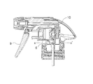
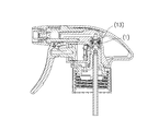
- FIG. 1 is a side sectional view of an accumulator spray.
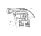
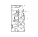
- FIG. 2 is an enlarged cross-sectional view of a portion where the S valve is incorporated.
- FIG. 3 is a side cross-sectional view of the pressure-accumulating spray in a state where the trigger is not pulled.
- FIG. 4 is a side cross-sectional view of the pressure-accumulating spray while the trigger is being pulled.
- FIG. 5 is a side cross-sectional view of the pressure-accumulating spray in a state where the trigger has been pulled.
- FIG. 6 is a side sectional view of the pressure-accumulating spray A while the trigger is being returned to the original position by the return spring portion.
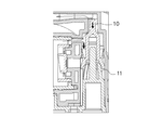
- FIG. 7 is a side cross-sectional view of the S valve showing a state where it is pushed down by the hydraulic pressure in the upper space.
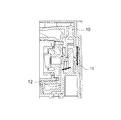
- FIG. 8 is a side cross-sectional view showing the state of the S valve when liquid leakage occurs.
- 9 is a cross-sectional view taken along the line XX ′ in FIG.
- FIG. 10 is a side sectional view of an S valve according to another embodiment.
- FIG. 11 is a side cross-sectional view of an S valve according to another embodiment.
- FIG. 12 is a side cross-sectional view of a prior art accumulator spray.
- FIG. 13 is a perspective view of a prior art accumulator spray.
- the present invention relates to a pressure-accumulating spray A that does not leak to the outside and does not cause a valve block phenomenon.
- a pressure accumulation spray A that does not leak to the outside and does not cause a valve block phenomenon.
- FIG. 1 is a side sectional view of the pressure accumulation spray A.
- the pressure-accumulating spray A of the present invention is attached to a container not shown in the figure, and the cylinder part 6 is filled with liquid, and the piston part 8 is moved to the right side in the figure by the rotation of the trigger 9.
- the pressure is applied to the liquid in the cylinder part 6 of the cylinder part 6 (at this time, the F valve 7 is closed and the S valve 10 is opened), and the liquid is injected from the nozzle part 5.
- the piston 8 is moved downstream (left side in the figure) by the return rotation of the trigger 9 to make the cylinder 6 negative pressure, and the liquid in the container is filled in the cylinder 6. Yes (At this time, the F valve 7 is open and the S valve 10 is closed).
- the F valve 7 is provided in the liquid passage 12 between the cylinder portion 6 and the container, while the S valve 10 is provided in the liquid passage 12 between the cylinder portion 6 and the nozzle portion 5.
- the pressure-accumulating spray A includes a nozzle portion 5, a body portion 3, a cylinder portion 6, a piston portion 8, a trigger 9, a return spring portion 13, an S valve 10, and an F valve 7.
- the base body 2 provided with the pressing spring part 11, the introduction pipe 4, and the cap part 1 are provided. Further, a cover body that covers the cylinder portion 6, the body portion 3, and the base body 2 is provided.
- the body portion 3 is provided with a cylinder receiving portion 31 having a space for press-fitting the cylinder portion 6 and a base body receiving portion 32 having a space for press-fitting the base body 2 below.
- the cylinder portion 6 is attached to the cylinder receiving portion 31 of the body portion 3 by press fitting
- the base body 2 is attached to the base body receiving portion 32 of the body portion 3 by press fitting.
- the nozzle portion 5 is attached to the upper portion of the body portion 3 by press fitting.
- the trigger 9 is attached to the body portion 3 so as to be rotatable, and the return spring portion 13 can be rotated to return.
- the body portion 3 includes the cylinder receiving portion 31 as described above, and the cylinder receiving portion 31 is formed in a cylindrical shape that opens to the front (nozzle portion side) in the middle of the body portion 3. .
- a rib 33 is formed on the lower end of the body portion 3 and the rib 33 is sandwiched between the upper end of the cap portion 1 and the container. Thereby, the body part 3 and the cap part 1 are assembled reliably.
- the base body receiving part 32 of the body part 3 is formed to open below the body part 3 corresponding to the shape of the base body 2.
- the base body 2 is attached to the mouth portion of the container via the cap portion 1 while being attached to the body portion 3.
- the base body 2 has a cylindrical fixing portion 21 and an upright cylindrical portion 22 extending upward.
- An introduction pipe 4 communicating with the container is attached by press-fitting below the center.
- a space having a certain size is defined above the base body receiving portion 32.
- An S valve 10 described later is disposed in the space.
- the pressing spring portion 11 and the above-described standing cylindrical portion 22 are arranged in the vertical direction at a position away from the center portion of the base body 2 in a top view (in other words, at a position eccentric from the mounting position of the introduction tube 4). Is done.
- the pressing spring portion 11 is integrally formed with the base body 2 by injection molding or the like. Specifically, the base body 2 is provided upright from the upper end of the upright cylindrical portion 22. This makes it possible to reduce the number of parts. Further, since the position of the pressing spring portion 11 is fixed by being integrally formed, the pressing force to the S valve 10 is accurately transmitted.
- the pressing spring portion 11 of this embodiment is formed in a slightly tapered cylindrical shape, and further, the cylindrical wall is missing at equal intervals.
- the pressing spring portion 11 is composed of three divided pieces.
- the elastic pressure of the pressing spring portion 11 is evenly transmitted to the S valve without deviation. More specifically, when the pressing spring portion 11 applies elastic force to the lower side of the flange portion 10c of the S valve 10, the shaft centers of the S valve 10 and the pressing spring portion 11 are maintained in a stable state. Moreover, since the pressing spring part 11 is a leaf
- the liquid passage 12 between the introduction pipe 4 and the F valve 7 is defined by the inner peripheral wall of the body portion 3 and the outer wall of the upright cylindrical portion 22 of the base body 2 and has a slit shape.
- the F valve 7 is provided between the cylinder portion 6 and the liquid passage 12. More specifically, the F valve 7 is provided at the bottom of the cylinder portion 6. The F valve 7 shuts off or merges the liquid on the container side and the liquid in the cylinder portion 6. In the F valve 7, after pressure is applied to the cylinder portion 6 and the liquid in the inside is ejected outward, the piston portion 8 attempts to return to the original position. The valve is opened when the liquid is drawn into the cylinder portion 6.
- the F valve 7 exhibits a valve function by the second valve body E2 and the second valve seat V2, and an annular protrusion formed at the bottom of the body portion 3 plays a role of the second valve seat V2. Yes.
- the second valve body E2 is in elastic contact with the second valve seat V2, and is separated when the valve is opened.
- the second valve element E2 of the F valve 7 is moved in parallel to the downstream side (left side in the figure) and opened by receiving pressure from the liquid sucked from the container.
- FIG. 2 is an enlarged cross-sectional view showing a portion where the S valve 10 is incorporated.
- the S valve 10 includes a first valve body E1, a valve lip portion 10a formed below the first valve body E1, and a flange portion 10b formed further below.
- the S valve 10 is arranged inside the body portion 3 (the space defined by the base body 2 and the inner peripheral wall of the body portion 3 described above).
- the inner peripheral wall of the body portion 3 in which the S valve 10 is disposed has a stepped portion V1 whose upper diameter is reduced.
- the step portion V1 functions as the first valve seat V1 of the S valve 10.
- the first valve body E1 of the S valve 10 has an inclined surface E1 facing the stepped portion V1, and the inclined surface E1 is in contact with the stepped portion V1 of the body portion 3.
- the inclined surface E ⁇ b> 1 of the S valve 10 is lifted upward by the pressing spring portion 11, and is in elastic contact with the stepped portion V ⁇ b> 1 on the inner peripheral wall of the body portion 3.
- a valve lip portion 10 a that gradually expands upward is provided below the S valve 10, and elastically contacts the inner peripheral wall of the body portion 3. That is, the valve lip portion 10a causes the upper space K1, which is a space between the inner peripheral wall of the body portion 3 and the first valve body E1 of the S valve 10, and the lower portion of the S valve 10 and the inner peripheral wall and base of the body portion 3.
- the lower space K2 that is a space between the body 2 and the body 2 is blocked.
- the upper space K1 is in a sealed state because the first valve seat V1 which is the stepped portion V1 of the body portion 3 and the first valve body E1 of the S valve 10 are in elastic contact. .
- the lower space K2 below the valve lip portion 10a communicates with the liquid passage 12 between the inner peripheral wall of the body portion 3 and the outer wall of the upright cylindrical portion 22 of the base body 2.
- a flange portion 10b extending downward in a skirt shape is provided below the valve lip portion 10a.
- the flange portion 10b slides with the inner peripheral wall of the body portion 3 to guide the S valve 10 when the S valve 10 moves up and down.
- the S valve 10 is moved by the trigger 9 and the hydraulic pressure is applied to the upper space K1 leading to the cylinder portion 6 to overcome the spring force of the pressing spring and slide downward. 3 opens (opens) between the first valve seat V1, which is the third stepped portion V1, and the inclined portion of the first valve body E1 of the S valve 10. Thereby, the liquid pushed out from the upper space K ⁇ b> 1 further flows to the nozzle part 5 and is ejected from the nozzle part 5 to the outside.
- the elastic pressure of the pressing spring portion 11 now pushes the S valve 10 upward, and the S valve 10 is the first step portion V1 of the body portion 3. It abuts on the valve seat V1 in an elastic manner (closes). Thereby, the upper space K1 is sealed again.
- FIG. 3 to 6 are diagrams illustrating a series of movements until the trigger 9 is pulled and the trigger 9 is returned to the original position by the return spring portion 13.
- FIG. 3 is a side sectional view of the pressure accumulating spray A in a state where the trigger 9 is not pulled.
- FIG. 4 is a side cross-sectional view of the pressure-accumulating spray A while the trigger 9 is being pulled.
- FIG. 5 is a side sectional view of the pressure accumulating spray A in a state where the trigger 9 has been pulled.
- FIG. 6 is a side cross-sectional view of the pressure-accumulating spray A while the trigger 9 is being returned to the original position by the return spring portion 13.
- FIG. 7 is a side cross-sectional view of the S valve 10 pushed down by the hydraulic pressure in the upper space K1.
- the liquid flow will be described.
- the liquid in the container is sucked up through the introduction pipe 4, sucked up to the cylinder part 6 through the F valve 7 through the liquid passage 12 between the inner peripheral wall of the body part 3 and the outer wall of the base body 2. It is done. Then, it pushes out to the upper space K1, reaches the nozzle part 5 through the S valve 10, and is sprayed outside.
- valve lip portion 10 a a problem may occur in the valve lip portion 10 a, and liquid may leak from the upper space K ⁇ b> 1 to the lower space K ⁇ b> 2.
- the lower space K2 specifically the space around the pressing spring portion 11, is filled with liquid, and when this is in a sealed state, a so-called valve block state is created in which the movement of the S valve 10 is hindered.
- this sealed state can be avoided.
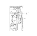
- FIG. 8 is an enlarged side sectional view of the S valve 10 when liquid leakage occurs.
- the pressing spring portion 11 is provided below the S valve 10, and when the hydraulic pressure above the S valve 10 becomes excessive or when the valve lip portion 10a is defective.
- the liquid filled above the S valve 10 enters the pressing spring portion 11 side (lower space K2) from the gap between the valve lip portion 10a and the inner peripheral wall of the body.
- the lower space K2 in which the pressing spring portion 11 is accommodated is continuous with the container via the liquid passage 12 formed between the inner peripheral wall of the body portion 3 and the outer wall of the upright cylindrical portion 22 of the base body 2. Therefore, the excess liquid is always in a state where it can escape to the container, and even if the liquid is filled, the vertical sliding of the S valve 10 is not hindered. That is, the valve block phenomenon does not occur.
- FIG. 9 is a sectional view taken along line XX ′ in FIG.
- the liquid passage 12 is defined by the outer wall of the base body 2 and the inner peripheral wall of the body portion 3. Since the lower space K2 immediately below the valve lip 10a is an integral space communicating with the liquid passage 12, when liquid leaks from the upper space K1 to the lower space K2 via the valve lip 10a. However, the leaked liquid passes through the liquid passage 12 to the introduction pipe 4 and is collected in the container. Thus, since the lower space K2 always communicates with the container through the liquid passage 12, even if the lower space K2 is filled with the liquid, the movement of the S valve 10 is not hindered and the valve block phenomenon occurs. Does not occur.
- the liquid does not leak to the outside, so that the surroundings are not soiled. Moreover, since the liquid collect
- the cylindrical wall of the pressing spring portion 11 is missing at regular intervals, but the number of divisions of the loss can be 2 or more.
- the shape of the mounting base can be changed.
- the mounting base portion has a shape in which a pressing spring portion integrally formed on the upper surface thereof has two cylindrical bodies stacked vertically (see FIG. 10). This cylindrical body is compressed by receiving pressure from above and exhibits a restoring force.
- the valve body of the S valve is pressed against the valve seat and closes.
- the pressing spring portion is separated from the mounting base portion and the S valve and is made of metal (see FIG. 11).
- raw materials such as a thermoplastic resin (resin pp) and a polyacetal (POM), are used suitably.
- the accumulator spray A of the present invention is widely used for the purpose of spraying liquid regardless of industrial use or home use.
- the excess liquid in the valve returns, so that the efficiency of use of the liquid is high and the surroundings are not soiled.
- the pressing spring portion 11 is integrally provided on the base body 2, the pressing force to the S valve acts efficiently, and high spraying efficiency can be expected as the pressure accumulation type spray A.
Landscapes
- Containers And Packaging Bodies Having A Special Means To Remove Contents (AREA)
- Closures For Containers (AREA)
Abstract
【課題】 液の外部への漏れをなくし、周囲の汚れや液の無駄をなくすることができる蓄圧式スプレーを提供する。 【解決手段】 キャップ部1と、該キャップ部に取り付け可能なボディ部3と、該ボディ部3に取り付けられたベース体2と、該ベース体2に取り付けられた容器の液を導入するための導入管4と、該ボディ部3に取り付けられたノズル部5と、該ボディ部3に取り付けられたシリンダ部6と、該シリンダ部6の底に取り付けられたFバルブ7と、該シリンダ部6内を摺動するピストン部8と、該ピストン部8を前後方向に移動させる回動可能なトリガー9と、該トリガー9を復帰させるための復帰バネ部13と、ボディ部3の通路に取り付けられた蓄圧バルブ(Sバルブ10)と、該蓄圧バルブを閉弁方向に押圧する押圧バネ部11と、を備え、トリガー9を回動させることにより、液体を噴出する蓄圧式スプレーであって、ベース体2とボディ部3との間にシリンダ部6内に通じる液通路12が形成されており、蓄圧バルブとベース体2との間にある液を該液通路12と導入管4を介して容器内に回収させる蓄圧式スプレー。
Description
本発明は、蓄圧式スプレーに関し、より詳しくは、外への液漏れが生じない蓄圧式スプレーに関する。
液噴出スプレーには、噴出力を高める特殊なSバルブを備えたいわゆる蓄圧式スプレーがある。
この蓄圧式スプレーは、一般に、シリンダに対してピストンをスライドさせることにより、一定圧を超えたシリンダ内の液体をノズルから噴出させる構造となっている。
ここで、液体の流通が開閉される部位は、弁体と弁座によって封鎖されており、Fバルブが閉じた状態において一定の圧力で蓄圧された液体がシリンダ内から押し出されることにより、Sバルブの弁体と弁座とが開放されるようになっている。
この場合、Sバルブの弁体がバネを介して弁座に押圧されており、シリンダ内の液圧がこの押圧力を超えると弁が開いて液が通過することとなる。
いきなり弁が開いて液圧が開放されるので、液体は勢い良く外部に噴出するが、この後、シリンダ内が放圧されて、Sバルブは再び封鎖する。
蓄圧式スプレーにおいては、このようにして、シリンダ内の液を勢い良く外部に噴出することが可能であり極めて有用である。
このような蓄圧式スプレーAとしては、例えば、本出願人によるものが幾つか出願されている(特許文献1、特許文献2等)。
例えば、容器に取り付けられた状態で、トリガー部(T)の回動によりピストン部(5)を移動させてシリンダ構造部(4)のシリンダ部内の液に圧を加え、容器の液を通路(P)を通してノズル部(3)から噴射させるトリガースプレイヤであって、シリンダ部と容器との間の通路に設けられたFバルブ(2)と、該シリンダ部(42A)とノズル部の間の通路部に設けられたSバルブ(1)と、を備え、Sバルブ(1)の弁体(11)が、起立円筒部(71)の弁座(12)に対して押圧されており、シリンダ部の液圧によって、弁体と弁座との間に間隙を生じさせ(開弁)、液を通過させるものがある(例えば、特許文献1参照)。
例えば、容器に取り付けられた状態で、トリガー部(T)の回動によりピストン部(5)を移動させてシリンダ構造部(4)のシリンダ部内の液に圧を加え、容器の液を通路(P)を通してノズル部(3)から噴射させるトリガースプレイヤであって、シリンダ部と容器との間の通路に設けられたFバルブ(2)と、該シリンダ部(42A)とノズル部の間の通路部に設けられたSバルブ(1)と、を備え、Sバルブ(1)の弁体(11)が、起立円筒部(71)の弁座(12)に対して押圧されており、シリンダ部の液圧によって、弁体と弁座との間に間隙を生じさせ(開弁)、液を通過させるものがある(例えば、特許文献1参照)。
しかしながら、上記特許文献1に記載の蓄圧式スプレーAにおいては、押圧バネ部がSバルブの上方に設けられているため、蓄圧バルブの液通路側と反対側に停留する液は、外部に逃がす構造とならざるを得ない。
すなわち図13のボディ部に逃がし孔Gが形成されており、押圧バネ部の存在する密閉空間の液を外部に逃がすものである。
停留する液を逃がさない場合、液が充満し押圧バネ部の動きを妨げるバルブロック現象が生じる。
液を外部に逃がす構造であるため、液が外部に漏れ出て周囲を汚す原因となったり、或いは液が外に漏れ出て無駄になり、液コストも増加する欠点がある。
すなわち図13のボディ部に逃がし孔Gが形成されており、押圧バネ部の存在する密閉空間の液を外部に逃がすものである。
停留する液を逃がさない場合、液が充満し押圧バネ部の動きを妨げるバルブロック現象が生じる。
液を外部に逃がす構造であるため、液が外部に漏れ出て周囲を汚す原因となったり、或いは液が外に漏れ出て無駄になり、液コストも増加する欠点がある。
本発明は上記事情を背景としてなされたものであり、液の外部への漏れをなくし、周囲の汚れや液の無駄をなくすることができる蓄圧式スプレーを提供することを目的とする。
本発明者は、上記課題を解決するため鋭意検討したところ、本来外部に逃がすべき液を、構造を工夫することで容器の中に戻して回収することにより、上記課題を解決し得ることを見出し、本発明を完成するに至った。
すなわち本発明は、(1)、キャップ部1と、該キャップ部1に取り付け可能なボディ部3と、該ボディ部3に取り付けられたベース体2と、該ベース体2に取り付けられた容器の液を導入するための導入管4と、該ボディ部3に取り付けられたノズル部5と、該ボディ部3に取り付けられたシリンダ部6と、該シリンダ部6の底に取り付けられたFバルブ7と、該シリンダ部6内を摺動するピストン部8と、該ピストン部8を前後方向に移動させる回動可能なトリガー9と、該トリガー9を復帰させるための復帰バネ部13と、ボディ部3の通路に取り付けられた蓄圧バルブ(Sバルブ10)と、該蓄圧バルブを閉弁方向に押圧する押圧バネ部11と、を備え、トリガー9を回動させることにより、液体を噴出する蓄圧式スプレーであって、ベース体2とボディ部3との間にシリンダ部6内に通じる液通路12が形成されており、蓄圧バルブとベース体2との間にある液を該液通路12と導入管4を介して容器内に回収させる蓄圧式スプレーAに存する。
すなわち本発明は、(2)押圧バネ部11とベース体2とが一体になっている上記(1)記載の蓄圧式スプレーAに存する。
すなわち本発明は、(3)押圧バネ部11と蓄圧バルブとが一体となっている上記(1)記載の蓄圧式スプレーAに存する。
すなわち本発明は、(4)、ベース体2の中央部に導入管4が取り付けられている上記(1)記載の蓄圧式スプレーAに存する。
すなわち本発明は、(5)、ベース体2の中央から偏芯した位置に押圧バネ部11が設けられた上記(1)記載の蓄圧式スプレーAに存する。
本発明は、キャップ部1と、該キャップ部に取り付け可能なボディ部3と、該ボディ部3に取り付けられたベース体2と、該ベース体2に取り付けられた容器の液を導入するための導入管4と、該ボディ部3に取り付けられたノズル部5と、該ボディ部3に取り付けられたシリンダ部6と、該シリンダ部6の底に取り付けられたFバルブ7と、該シリンダ部6内を摺動するピストン部8と、該ピストン部8を前後方向に移動させる回動可能なトリガー9と、該トリガー9を復帰させるための復帰バネ部13と、ボディ部3の通路に取り付けられた蓄圧バルブ(Sバルブ10)と、該蓄圧バルブを閉弁方向に押圧する押圧バネ部11と、を備え、トリガー9を回動させることにより、液体を噴出する蓄圧式スプレーであって、ベース体2とボディ部3との間にシリンダ部6内に通じる液通路12が形成されており、蓄圧バルブとベース体2との間にある液を該液通路12と導入管4を介して容器内に回収させることにより、液漏れが発生した場合でも、液が外部へ漏れ出て周囲を汚損することがなく、また、バルブロック現象が生じない。加えて、液が容器に回収されて再度噴霧に用いることができる。
また、本発明は、押圧バネ部11とベース体2とが一体になっていることにより、部品点数が少なく組み付けが容易であり、蓄圧式スプレーAを製造する際の組み付け工数が少なくなる。また、製造コストを削減できる。
また、本発明は、押圧バネ部11と蓄圧バルブとが一体となっていることにより、部品点数が少なく組み付けが容易であり、蓄圧式スプレーAを製造する際の組み付け工数が少なくなる。また、製造コストを削減できる。
また、本発明は、ベース体2の中央部に導入管4が取り付けられていることにより、液漏れが生じた際にも、液の容器への回収をスムーズに行うことができる。
また、本発明は、ベース体2の中央から偏芯した位置に押圧バネ部11が設けられたことにより、バルブ内に残留する過剰な液を効率的に容器に回収できる。
以下、必要に応じて図面を参照しつつ、本発明の好適な実施形態について詳細に説明する。
なお、図面中、同一要素には同一符号を付すこととし、重複する説明は省略する。
また、上下左右等の位置関係は、特に断らない限り、図面に示す位置関係に基づくものとする。
更に、図面の寸法比率は図示の比率に限られるものではない。
なお、図面中、同一要素には同一符号を付すこととし、重複する説明は省略する。
また、上下左右等の位置関係は、特に断らない限り、図面に示す位置関係に基づくものとする。
更に、図面の寸法比率は図示の比率に限られるものではない。
(実施の形態)
本発明は、外への液漏れが生じず、バルブロック現象が生じない蓄圧式スプレーAに関するものである。
以下、蓄圧式スプレーAの一例について述べる。
本発明は、外への液漏れが生じず、バルブロック現象が生じない蓄圧式スプレーAに関するものである。
以下、蓄圧式スプレーAの一例について述べる。
図1は、蓄圧式スプレーAの側面断面図である。
本発明の蓄圧式スプレーAは、機能についていうと、図に示さない容器に取り付けられ、シリンダ部6内に液が充填した状態で、トリガー9の回動によりピストン部8を図でいう右側に移動させてシリンダ部6のシリンダ部6内の液に圧を加え(この時、Fバルブ7は閉じており、Sバルブ10は開いている)、ノズル部5から噴射させるものである。
本発明の蓄圧式スプレーAは、機能についていうと、図に示さない容器に取り付けられ、シリンダ部6内に液が充填した状態で、トリガー9の回動によりピストン部8を図でいう右側に移動させてシリンダ部6のシリンダ部6内の液に圧を加え(この時、Fバルブ7は閉じており、Sバルブ10は開いている)、ノズル部5から噴射させるものである。
また、反対にトリガー9の復帰回動によりピストン部8を下流側(図における左側)に移動させて、シリンダ部6内を負圧化し、容器内の液をシリンダ部6内に充填させるものである(この時、Fバルブ7は開いており、Sバルブ10は閉じている)。
尚、Fバルブ7はシリンダ部6と容器との間の液通路12に設けられ、他方、Sバルブ10はシリンダ部6とノズル部5の間の液通路12に設けられている。
構造についていうと、蓄圧式スプレーAは、ノズル部5と、ボディ部3と、シリンダ部6と、ピストン部8と、トリガー9と、復帰バネ部13と、Sバルブ10と、Fバルブ7と、押圧バネ部11を備えたベース体2と、導入管4と、キャップ部1と、を備えている。
また、シリンダ部6やボディ部3やベース体2を覆うカバー体を備えている。
また、シリンダ部6やボディ部3やベース体2を覆うカバー体を備えている。
ボディ部3には、シリンダ部6を圧入するための空間を有するシリンダ受入部31と、下方にベース体2を圧入するための空間を有するベース体受入部32が設けられている。
シリンダ部6はボディ部3のシリンダ受入部31に圧入により、また、ベース体2はボディ部3のベース体受入部32に圧入により取り付けられる。
また、ノズル部5はボディ部3の上方に圧入により取り付けられる。
シリンダ部6はボディ部3のシリンダ受入部31に圧入により、また、ベース体2はボディ部3のベース体受入部32に圧入により取り付けられる。
また、ノズル部5はボディ部3の上方に圧入により取り付けられる。
トリガー9はボディ部3に回動可能に取り付けられており、復帰バネ部13により復帰の回動が可能である。
次に、蓄圧式スプレーAを構成する各部品について述べる。
まず、ボディ部3は、先述したようにシリンダ受入部31を備えるが、このシリンダ受入部31は、ボディ部3の中ほどで、前方(ノズル部側)へ開口した円筒状に形成されている。
まず、ボディ部3は、先述したようにシリンダ受入部31を備えるが、このシリンダ受入部31は、ボディ部3の中ほどで、前方(ノズル部側)へ開口した円筒状に形成されている。
また、ボディ部3の下端には外方にリブ33が形成されており、該リブ33がキャップ部1の上端と容器により挟み込まれる。
これにより、ボディ部3とキャップ部1が確実に組み立てられる。
これにより、ボディ部3とキャップ部1が確実に組み立てられる。
ボディ部3のベース体受入部32は、ベース体2の形状に対応してボディ部3の下方に開口して形成されている。ベース体2はボディ部3に取り付けられた状態で、キャップ部1を介して容器の口部に取り付けられる。
ベース体2は、詳しくは円筒状の固定部21と、それより上方に伸びる起立円筒部22とを有している。
そして中央部下方には、容器へと連絡する導入管4が圧入により取り付けられる。
そして中央部下方には、容器へと連絡する導入管4が圧入により取り付けられる。
ボディ部3のベース体受入部32にベース体2の起立円筒部22が取り付けられた状態では、ベース体受入部32の上部に一定の広さの空間が画される。該空間には、後述するSバルブ10が配設される。
また、上面視でベース体2の中央部から離れた位置に(換言すると導入管4の取り付け位置から偏芯した地位に)押圧バネ部11と上述した起立円筒部22とが上下方向に配設される。
ここで、この押圧バネ部11はベース体2と射出成型等により一体形成されている。詳しくはベース体2の起立円筒部22上端から起立して設けられる。このことにより部品点数の削減を図ることが可能となる。
また一体形成されることにより押圧バネ部11の位置が固定されるので、Sバルブ10への押圧力が的確に伝達される。
この実施形態の押圧バネ部11はやや先細りした円筒状に形成され、さらに、その円筒壁が等間隔に欠損されてなるものである。
本実施の形態では、欠損が3箇所となっており押圧バネ部11が3分割片よりなる例で示す。
このことにより、押圧バネ部11の弾圧力が、偏りなく均等にSバルブへ伝達される。
更にいうと、Sバルブ10の鍔部10cの下側に対し押圧バネ部11が弾圧力を与える際に、Sバルブ10及び押圧バネ部11の軸心が安定した状態で維持される。
また、押圧バネ部11は板バネであることから、高い弾圧力が得られる。
導入管4とFバルブ7の間の液通路12は、ボディ部3の内周壁と、ベース体2の起立円筒部22の外壁により画され、スリット状となっている。
Fバルブ7はシリンダ部6と該液通路12との間に設けられており、詳しくはシリンダ部6の底部に設けられている。
このFバルブ7は容器側の液とシリンダ部6内の液を遮断或いは合流させるものである。
Fバルブ7は、シリンダ部6に圧が加えられ、内部の液が外方に噴出した後、ピストン部8が元の位置に戻ろうとするため、シリンダ部6内が減圧され、液通路12から液がシリンダ部6内へ引き込まれることにより開弁される。
このFバルブ7は容器側の液とシリンダ部6内の液を遮断或いは合流させるものである。
Fバルブ7は、シリンダ部6に圧が加えられ、内部の液が外方に噴出した後、ピストン部8が元の位置に戻ろうとするため、シリンダ部6内が減圧され、液通路12から液がシリンダ部6内へ引き込まれることにより開弁される。
Fバルブ7は第2弁体E2と第2弁座V2とにより弁機能を発揮するもので、ボディ部3の底部に形成された環状の突起部がこの第2弁座V2の役割を担っている。
通常時、第2弁体E2は第2弁座V2に対して弾圧的に当接しており、開弁時に離れる。
通常時、第2弁体E2は第2弁座V2に対して弾圧的に当接しており、開弁時に離れる。
すなわち、容器から吸い上げられてくる液により圧力を受けて、Fバルブ7の第2弁体E2は下流側(図で左側)に平行移動し、開弁する。
次にSバルブ10について述べる。図2は、Sバルブ10の組み込まれた部分を拡大して示す断面図である。Sバルブ10は第1弁体E1、該第1弁体E1の下方に形成されたバルブリップ部10a及び更に下方に形成された鍔部10bよりなる。
Sバルブ10はボディ部3の内部(先述した、ベース体2とボディ部3内周壁で画される空間)に配される。
Sバルブ10が配されるボディ部3の内周壁は、上方が縮径された段差部V1を有している。この段差部V1がSバルブ10の第1弁座V1の機能を担う。
Sバルブ10の第1弁体E1は該段差部V1に対向する傾斜面E1を有し、該傾斜面E1がボディ部3の段差部V1に当接している。
Sバルブ10のこの傾斜面E1は、押圧バネ部11により上方へ持ち上げられることによって、ボディ部3の内周壁の段差部V1と弾圧的に当接している。
Sバルブ10が配されるボディ部3の内周壁は、上方が縮径された段差部V1を有している。この段差部V1がSバルブ10の第1弁座V1の機能を担う。
Sバルブ10の第1弁体E1は該段差部V1に対向する傾斜面E1を有し、該傾斜面E1がボディ部3の段差部V1に当接している。
Sバルブ10のこの傾斜面E1は、押圧バネ部11により上方へ持ち上げられることによって、ボディ部3の内周壁の段差部V1と弾圧的に当接している。
Sバルブ10の下方には、上方へ向けて漸次拡大するバルブリップ部10aが設けられ、ボディ部3の内周壁に対して弾圧的に当接している。
すなわち、バルブリップ部10aにより、ボディ部3の内周壁とSバルブ10の第1弁体E1との間の空間である上空間K1と、Sバルブ10下方とボディ部3の内周壁及びベ ース体2との間の空間である下空間K2が遮断されている。
すなわち、バルブリップ部10aにより、ボディ部3の内周壁とSバルブ10の第1弁体E1との間の空間である上空間K1と、Sバルブ10下方とボディ部3の内周壁及びベ ース体2との間の空間である下空間K2が遮断されている。
上述したように、ボディ部3の段差部V1である第1弁座V1とSバルブ10の第1弁体E1が弾圧的に当接していることにより、上空間K1は密閉された状態にある。
他方、バルブリップ部10aより下方の下空間K2は、ボディ部3の内周壁とベース体2の起立円筒部22の外壁との間の液通路12とい連通している。
バルブリップ部10aの下方には下方へ向けてスカート状に延出する鍔部10bが設けられる。鍔部10bは、Sバルブ10が上下に移動する際にボディ部3内周壁と摺動し、Sバルブ10をガイドする。
Sバルブ10は、トリガー9操作によりピストン部8が移動して、シリンダ部6に通じる上空間K1に液圧がかかることにより押圧バネのバネ力に打ち勝って下方に摺動し、先述したボディ部3の段差部V1である第1弁座V1と、Sバルブ10の第1弁体E1の傾斜部との間が開く(開弁する)。
これにより、上空間K1から押し出された液は、さらにノズル部5へと流れ、ノズル部5より外部へと噴出する。
液が噴出され、上空間K1にかかる液圧が下がると、今度は押圧バネ部11の弾圧力がSバルブ10を上方へと押し上げ、Sバルブ10はボディ部3の段差部V1である第1弁座V1に弾圧的に当接する(閉弁する)。
これにより、上空間K1が再度密封される。
これにより、上空間K1から押し出された液は、さらにノズル部5へと流れ、ノズル部5より外部へと噴出する。
液が噴出され、上空間K1にかかる液圧が下がると、今度は押圧バネ部11の弾圧力がSバルブ10を上方へと押し上げ、Sバルブ10はボディ部3の段差部V1である第1弁座V1に弾圧的に当接する(閉弁する)。
これにより、上空間K1が再度密封される。
Sバルブ10が閉弁した状態で、トリガー9は復帰バネ部13によって元の位置に戻る。この際、トリガー9によってピストン部8が移動されるとシリンダ内が負圧化し、容器内の液が導入管4を介して、Fバルブ7を通ってシリンダ内に引き込まれる(Sバルブ10は閉じ、Fバルブ7は開く)。
図3~図6はトリガー9を引いて、トリガー9が復帰バネ部13により元の位置に戻るまでの一連の動きを示す図である。
図3はトリガー9を引いていない状態の蓄圧式スプレーAの側面断面図である。
図4は、トリガー9を引いている途中の蓄圧式スプレーAの側面断面図である。
図5はトリガー9を引き終わった状態の蓄圧式スプレーAの側面断面図である。
図6は、復帰バネ部13により、トリガー9が元の位置へ戻っている途中の蓄圧式スプレーAの側面断面図である。
図7は、上空間K1内の液圧により押し下げられたSバルブ10の側面断面図である。
図3はトリガー9を引いていない状態の蓄圧式スプレーAの側面断面図である。
図4は、トリガー9を引いている途中の蓄圧式スプレーAの側面断面図である。
図5はトリガー9を引き終わった状態の蓄圧式スプレーAの側面断面図である。
図6は、復帰バネ部13により、トリガー9が元の位置へ戻っている途中の蓄圧式スプレーAの側面断面図である。
図7は、上空間K1内の液圧により押し下げられたSバルブ10の側面断面図である。
次に、液の流れについて言う。トリガー9の操作によって容器内の液は導入管4を通じて吸い上げられ、ボディ部3の内周壁とベース体2の外壁との間の液通路12を通じ、Fバルブ7を通ってシリンダ部6へと吸い上げられる。
その後、上空間K1へと押し出され、Sバルブ10を通ってノズル部5へ至り、外部へ噴霧される。
その後、上空間K1へと押し出され、Sバルブ10を通ってノズル部5へ至り、外部へ噴霧される。
ここで蓄圧式トリガー9においては、バルブリップ部10aに不具合が生じ、上空間K1から下空間K2へ液が漏れ出る場合が生じ得る。
これらによって、下空間K2、具体的には押圧バネ部11の周囲の空間に液が充填され、これが密閉状態にあると、Sバルブ10の動きが妨げられるいわゆるバルブロックの状態が生じる。
しかし、本発明の蓄圧式スプレーAにおいてはこの密閉状態が回避できる。
これらによって、下空間K2、具体的には押圧バネ部11の周囲の空間に液が充填され、これが密閉状態にあると、Sバルブ10の動きが妨げられるいわゆるバルブロックの状態が生じる。
しかし、本発明の蓄圧式スプレーAにおいてはこの密閉状態が回避できる。
図8は、液漏れが生じた際のSバルブ10の拡大側面断面図である。
すなわち、本発明のSバルブ10は、押圧バネ部11がSバルブ10の下方に設けられており、Sバルブ10上方の液圧が過剰になった際や、バルブリップ部10aに不具合が生じた場合、Sバルブ10上方に充填された液はバルブリップ部10aとボディ内周壁の間隙から押圧バネ部11の側(下空間K2)に入り込む。
ところが本発明では、押圧バネ部11が収まる下空間K2は、ボディ部3の内周壁とベース体2の起立円筒部22の外壁との間に形成された液通路12を介して容器と連続しているため、過剰な液は常に容器へ逃げられる状態であり、液が充填していてもSバルブ10の上下の摺動が妨げられることがない。すなわち、バルブロック現象が生じない。
ところが本発明では、押圧バネ部11が収まる下空間K2は、ボディ部3の内周壁とベース体2の起立円筒部22の外壁との間に形成された液通路12を介して容器と連続しているため、過剰な液は常に容器へ逃げられる状態であり、液が充填していてもSバルブ10の上下の摺動が妨げられることがない。すなわち、バルブロック現象が生じない。
図9は、図3におけるX-X´断面図である
先述した通り、液通路12はベース体2の外壁とボディ部3内周壁により画されている。
バルブリップ部10aの直下にある下空間K2は、液通路12と連絡する一体の空間となっているため、上空間K1から下空間K2へバルブリップ部10aを介して液漏れが生じた場合にも、その漏れ出た液が液通路12を通って導入管4へ至り、容器に回収される。
このように下空間K2は液通路12を通じて容器まで常に連通しているため、下空間K2に液が充填されている状態であっても、Sバルブ10の動きを妨げることがなく、バルブロック現象が生じない。
バルブリップ部10aの直下にある下空間K2は、液通路12と連絡する一体の空間となっているため、上空間K1から下空間K2へバルブリップ部10aを介して液漏れが生じた場合にも、その漏れ出た液が液通路12を通って導入管4へ至り、容器に回収される。
このように下空間K2は液通路12を通じて容器まで常に連通しているため、下空間K2に液が充填されている状態であっても、Sバルブ10の動きを妨げることがなく、バルブロック現象が生じない。
したがって、従来のように外部への逃がし穴を作る機構と異なり、外部に液が漏れないので周囲を汚損することがない。
また、容器に回収された液は再度噴霧のために利用することができるため、無駄がない。
また、容器に回収された液は再度噴霧のために利用することができるため、無駄がない。
以上、本発明の好適な実施形態について説明したが、本発明は上記実施形態に限定されるものではない。
押圧バネ部11の円筒壁は等間隔で欠損されているが、その欠損の分割数は2以上とすることができる。
取り付けベース部の形状を変更できる。例えば、取り付けベース部を、その上面に一体に形成されている押圧バネ部が円筒体を2つ上下に重ねた形状をしたものとすることが考えられる(図10参照)。
この円筒体が上から圧を受けることにより圧縮されて復帰力を発揮するものである。
Sバルブの下面がこの円筒体の上に形成された円板に当接し円筒体がやや圧縮された状態にあると、Sバルブの弁体が弁座に圧接して閉弁する。
この円筒体が上から圧を受けることにより圧縮されて復帰力を発揮するものである。
Sバルブの下面がこの円筒体の上に形成された円板に当接し円筒体がやや圧縮された状態にあると、Sバルブの弁体が弁座に圧接して閉弁する。
また、押圧バネ部を取り付けベース部やSバルブとは別体とし、金属によって設けることが考えられる(図11参照)。
なお、以上説明したベース体2の材質としては、熱可塑性樹脂(樹脂pp)、ポリアセタール(POM)等の素材が好適に用いられる。
本発明の蓄圧式スプレーAは、工業用、家庭用を問わず液体を噴霧する目的に広く用いられる。
過剰なバルブ内の液が、戻るため液の利用効率が高く、また周囲を汚損することがない。
加えて、ベース体2に押圧バネ部11が一体に設けられているため、Sバルブへの押圧力が効率よく作用し、蓄圧式スプレーAとして高い噴霧効率が期待できるものである。
過剰なバルブ内の液が、戻るため液の利用効率が高く、また周囲を汚損することがない。
加えて、ベース体2に押圧バネ部11が一体に設けられているため、Sバルブへの押圧力が効率よく作用し、蓄圧式スプレーAとして高い噴霧効率が期待できるものである。
A・・・蓄圧式スプレー
1・・・キャップ部
2・・・ベース体
21・・・固定部
22・・・起立円筒部
3・・・ボディ部
31・・・シリンダ受入部
32・・・ベース体受入部
33・・・リブ
4・・・導入管
5・・・ノズル部
6・・・シリンダ部
7・・・Fバルブ
8・・・ピストン部
9・・・トリガー
10・・・Sバルブ
10a・・・バルブリップ部
10b・・・鍔部
11・・・押圧バネ部
12・・・液通路
13・・・復帰バネ部
E1・・・第1弁体(傾斜面)
E2・・・第2弁体
V1・・・第1弁座(段差部)
V2・・・第2弁座
K1・・・上空間
K2・・・下空間
1・・・キャップ部
2・・・ベース体
21・・・固定部
22・・・起立円筒部
3・・・ボディ部
31・・・シリンダ受入部
32・・・ベース体受入部
33・・・リブ
4・・・導入管
5・・・ノズル部
6・・・シリンダ部
7・・・Fバルブ
8・・・ピストン部
9・・・トリガー
10・・・Sバルブ
10a・・・バルブリップ部
10b・・・鍔部
11・・・押圧バネ部
12・・・液通路
13・・・復帰バネ部
E1・・・第1弁体(傾斜面)
E2・・・第2弁体
V1・・・第1弁座(段差部)
V2・・・第2弁座
K1・・・上空間
K2・・・下空間
Claims (5)
- キャップ部と、
該キャップ部に取り付け可能なボディ部と、
該ボディ部に取り付けられたベース体と、
該ベース体に取り付けられた容器の液を導入するための導入管と、
該ボディ部に取り付けられたノズル部と、
該ボディ部に取り付けられたシリンダ部と、
該シリンダ部の底に取り付けられたFバルブと、
該シリンダ部内を摺動するピストン部と、
該ピストン部を前後方向に移動させる回動可能なトリガーと、
該トリガーを復帰させるための復帰バネ部と、
ボディ部の通路に取り付けられた蓄圧バルブと、
該蓄圧バルブを閉弁方向に押圧する押圧バネ部と、
を備え、トリガーを回動させることにより、液体を噴出する蓄圧式スプレーであって、ベース体とボディ部との間にシリンダ部内に通じる液通路が形成されており、
蓄圧バルブとベース体との間にある液を該液通路と導入管を介して容器内に回収させる蓄圧式スプレー。 - 押圧バネ部とベース体とが一体になっていることを特徴とする請求項1記載の蓄圧式スプレー。
- 押圧バネ部と蓄圧バルブとが一体となっていることを特徴とする請求項1記載の蓄圧式スプレー。
- ベース体の中央部に導入管が取り付けられていることを特徴とする請求項1記載の蓄圧式スプレー。
- ベース体の中央から偏芯した位置に押圧バネ部が設けられたことを特徴とする請求項1記載の蓄圧式スプレー。
Priority Applications (3)
| Application Number | Priority Date | Filing Date | Title |
|---|---|---|---|
| US16/313,020 US11027299B2 (en) | 2016-06-24 | 2017-06-08 | Pressurized sprayer |
| EP17815201.3A EP3476765A4 (en) | 2016-06-24 | 2017-06-08 | PRESSURE SPRAY CAN |
| CN201780038106.2A CN109311570B (zh) | 2016-06-24 | 2017-06-08 | 储压式喷雾装置 |
Applications Claiming Priority (2)
| Application Number | Priority Date | Filing Date | Title |
|---|---|---|---|
| JP2016-126094 | 2016-06-24 | ||
| JP2016126094A JP6833361B2 (ja) | 2016-06-24 | 2016-06-24 | 蓄圧式スプレー |
Publications (1)
| Publication Number | Publication Date |
|---|---|
| WO2017221732A1 true WO2017221732A1 (ja) | 2017-12-28 |
Family
ID=60783352
Family Applications (1)
| Application Number | Title | Priority Date | Filing Date |
|---|---|---|---|
| PCT/JP2017/021325 WO2017221732A1 (ja) | 2016-06-24 | 2017-06-08 | 蓄圧式スプレー |
Country Status (5)
| Country | Link |
|---|---|
| US (1) | US11027299B2 (ja) |
| EP (1) | EP3476765A4 (ja) |
| JP (1) | JP6833361B2 (ja) |
| CN (1) | CN109311570B (ja) |
| WO (1) | WO2017221732A1 (ja) |
Families Citing this family (3)
| Publication number | Priority date | Publication date | Assignee | Title |
|---|---|---|---|---|
| JP6833361B2 (ja) * | 2016-06-24 | 2021-02-24 | キャニヨン株式会社 | 蓄圧式スプレー |
| JP7304806B2 (ja) * | 2019-12-26 | 2023-07-07 | 株式会社吉野工業所 | トリガー式液体噴出器 |
| WO2023127892A1 (ja) * | 2021-12-28 | 2023-07-06 | 株式会社吉野工業所 | トリガー式液体噴出器 |
Citations (3)
| Publication number | Priority date | Publication date | Assignee | Title |
|---|---|---|---|---|
| JPH1176885A (ja) * | 1997-09-04 | 1999-03-23 | Kao Corp | スプレー容器 |
| WO2016068191A1 (ja) * | 2014-10-31 | 2016-05-06 | 株式会社吉野工業所 | トリガー式液体噴出器 |
| JP2016112484A (ja) * | 2014-12-11 | 2016-06-23 | キャニヨン株式会社 | トリガー式蓄圧スプレー |
Family Cites Families (27)
| Publication number | Priority date | Publication date | Assignee | Title |
|---|---|---|---|---|
| US5425482A (en) * | 1990-10-25 | 1995-06-20 | Contico International, Inc. | Trigger sprayer |
| US5425477A (en) * | 1994-06-29 | 1995-06-20 | Monturas, S.A. | Pump sprayer with stationary discharge |
| US5622317A (en) * | 1994-12-12 | 1997-04-22 | Contico International, Inc. | Pressure buildup trigger sprayer |
| JP3452283B2 (ja) * | 1995-01-30 | 2003-09-29 | 株式会社吉野工業所 | トリガー式噴霧器 |
| JPH08338359A (ja) * | 1995-06-09 | 1996-12-24 | Kao Corp | 吐出装置 |
| JPH08338360A (ja) * | 1995-06-14 | 1996-12-24 | Kao Corp | 吐出装置 |
| CA2184849A1 (en) * | 1995-09-27 | 1997-03-28 | Donald D. Foster | Liquid dispenser with trigger sprayer |
| JP3655414B2 (ja) * | 1996-11-20 | 2005-06-02 | 株式会社吉野工業所 | トリガー式液体噴出器 |
| JP3647615B2 (ja) * | 1997-07-28 | 2005-05-18 | 株式会社吉野工業所 | トリガー式液体噴出容器 |
| US6116472A (en) * | 1998-12-15 | 2000-09-12 | Calmar Inc. | Trigger acutated pump sprayer |
| US6131820A (en) * | 1999-06-01 | 2000-10-17 | Calmar Inc. | Discharge valve assembly for trigger sprayer |
| ITMI20030080A1 (it) * | 2003-01-21 | 2004-07-22 | Spray Plast Spa | Dispositivo spruzzatore semplificato. |
| US7311227B2 (en) * | 2004-10-08 | 2007-12-25 | Continental Afa Dispensing Company | Trigger sprayer venting system with reduced drag on vent piston |
| US20060289679A1 (en) * | 2005-06-27 | 2006-12-28 | Johnson Kaj A | Modular sprayer |
| US7497358B2 (en) * | 2006-03-15 | 2009-03-03 | Meadwestvaco Calmar, Inc. | Trigger sprayer with integral piston rod and bowed spring |
| US7775405B2 (en) * | 2006-12-22 | 2010-08-17 | Meadwestvaco Calmar, Inc. | Sprayer including pressure build-up discharge valve assembly with poppet valve having integrated spring |
| US8684235B2 (en) * | 2007-02-14 | 2014-04-01 | Kao Corporation | Trigger-type liquid sprayer |
| IT1399591B1 (it) * | 2010-04-14 | 2013-04-26 | Guala Dispensing Spa | Erogatore a grilletto per liquidi con valvole di testa. |
| JP5598924B2 (ja) * | 2011-02-28 | 2014-10-01 | 株式会社吉野工業所 | トリガー式液体噴出器 |
| US8469291B2 (en) * | 2011-05-11 | 2013-06-25 | Meadwestvaco Calmar, Inc. | Low cost trigger sprayer |
| JP2013056697A (ja) * | 2011-09-08 | 2013-03-28 | Tetsuya Tada | 蓄圧式トリガースプレイヤー及びその蓄圧バルブ |
| ITMI20112168A1 (it) * | 2011-11-28 | 2013-05-29 | Mwv Vicenza S P A | Spruzzatore per liquidi con camera di precompressione |
| JP6258128B2 (ja) * | 2014-05-30 | 2018-01-10 | 株式会社吉野工業所 | トリガー式液体噴出器 |
| JP6583715B2 (ja) | 2015-07-01 | 2019-10-02 | キャニヨン株式会社 | トリガースプレイヤ |
| JP6723062B2 (ja) * | 2016-04-25 | 2020-07-15 | キャニヨン株式会社 | トリガースプレイヤ |
| JP6723093B2 (ja) * | 2016-06-24 | 2020-07-15 | キャニヨン株式会社 | 蓄圧式スプレーのベース体及びベース体を備えた蓄圧式スプレー |
| JP6833361B2 (ja) * | 2016-06-24 | 2021-02-24 | キャニヨン株式会社 | 蓄圧式スプレー |
-
2016
- 2016-06-24 JP JP2016126094A patent/JP6833361B2/ja active Active
-
2017
- 2017-06-08 CN CN201780038106.2A patent/CN109311570B/zh active Active
- 2017-06-08 US US16/313,020 patent/US11027299B2/en active Active
- 2017-06-08 EP EP17815201.3A patent/EP3476765A4/en not_active Withdrawn
- 2017-06-08 WO PCT/JP2017/021325 patent/WO2017221732A1/ja unknown
Patent Citations (3)
| Publication number | Priority date | Publication date | Assignee | Title |
|---|---|---|---|---|
| JPH1176885A (ja) * | 1997-09-04 | 1999-03-23 | Kao Corp | スプレー容器 |
| WO2016068191A1 (ja) * | 2014-10-31 | 2016-05-06 | 株式会社吉野工業所 | トリガー式液体噴出器 |
| JP2016112484A (ja) * | 2014-12-11 | 2016-06-23 | キャニヨン株式会社 | トリガー式蓄圧スプレー |
Non-Patent Citations (1)
| Title |
|---|
| See also references of EP3476765A4 * |
Also Published As
| Publication number | Publication date |
|---|---|
| US20190217317A1 (en) | 2019-07-18 |
| EP3476765A4 (en) | 2020-03-11 |
| US11027299B2 (en) | 2021-06-08 |
| JP2017226474A (ja) | 2017-12-28 |
| CN109311570B (zh) | 2020-09-08 |
| EP3476765A1 (en) | 2019-05-01 |
| JP6833361B2 (ja) | 2021-02-24 |
| CN109311570A (zh) | 2019-02-05 |
Similar Documents
| Publication | Publication Date | Title |
|---|---|---|
| US9199783B2 (en) | Plastic valves and methods of using the same | |
| WO2017221732A1 (ja) | 蓄圧式スプレー | |
| US8672191B2 (en) | Manual spray pump | |
| US8006870B2 (en) | Discharger for a flowable medium | |
| KR100692457B1 (ko) | 축압식 액체 분출기 | |
| US11154888B2 (en) | Spray pump | |
| CA2964820A1 (en) | Pump dispensers | |
| US11383257B2 (en) | All-plastic self-locking pump | |
| US4087025A (en) | Leakproof pump for hand-held dispensers | |
| JP2008055333A (ja) | 押下げヘッド | |
| WO2017221731A1 (ja) | 蓄圧式スプレーのベース体及びベース体を備えた蓄圧式スプレー | |
| AU2017236368B2 (en) | Metering pump for a metering device and metering device | |
| JP2010269221A (ja) | ピストンシリンダユニット | |
| JP4038344B2 (ja) | 蓄圧式液体噴出器 | |
| JP6144099B2 (ja) | ポンプ式噴霧容器の外気導入機構 | |
| JPH07144159A (ja) | プッシュタイプディスペンサ− | |
| JP2017013811A (ja) | 吐出容器 | |
| JP2577913Y2 (ja) | ディスペンサー | |
| JP3986947B2 (ja) | ポンプユニット及び容器 | |
| JP5574370B2 (ja) | 正倒立噴出可能な液体噴出器 | |
| JP2556686Y2 (ja) | ディスペンサー | |
| JPH0615853Y2 (ja) | 縦型ポンプ式液体噴出容器 | |
| JP3012183U (ja) | ディスペンサー | |
| JP2023125551A (ja) | 吐出器 | |
| JP2022069928A (ja) | 吐出器 |
Legal Events
| Date | Code | Title | Description |
|---|---|---|---|
| 121 | Ep: the epo has been informed by wipo that ep was designated in this application |
Ref document number: 17815201 Country of ref document: EP Kind code of ref document: A1 |
|
| NENP | Non-entry into the national phase |
Ref country code: DE |
|
| ENP | Entry into the national phase |
Ref document number: 2017815201 Country of ref document: EP Effective date: 20190124 |