WO2017221664A1 - 携帯端末 - Google Patents
携帯端末 Download PDFInfo
- Publication number
- WO2017221664A1 WO2017221664A1 PCT/JP2017/020460 JP2017020460W WO2017221664A1 WO 2017221664 A1 WO2017221664 A1 WO 2017221664A1 JP 2017020460 W JP2017020460 W JP 2017020460W WO 2017221664 A1 WO2017221664 A1 WO 2017221664A1
- Authority
- WO
- WIPO (PCT)
- Prior art keywords
- display
- unit
- display area
- displayed
- sensor
- Prior art date
Links
Images


Classifications
-
- G—PHYSICS
- G03—PHOTOGRAPHY; CINEMATOGRAPHY; ANALOGOUS TECHNIQUES USING WAVES OTHER THAN OPTICAL WAVES; ELECTROGRAPHY; HOLOGRAPHY
- G03B—APPARATUS OR ARRANGEMENTS FOR TAKING PHOTOGRAPHS OR FOR PROJECTING OR VIEWING THEM; APPARATUS OR ARRANGEMENTS EMPLOYING ANALOGOUS TECHNIQUES USING WAVES OTHER THAN OPTICAL WAVES; ACCESSORIES THEREFOR
- G03B13/00—Viewfinders; Focusing aids for cameras; Means for focusing for cameras; Autofocus systems for cameras
- G03B13/02—Viewfinders
-
- H—ELECTRICITY
- H04—ELECTRIC COMMUNICATION TECHNIQUE
- H04N—PICTORIAL COMMUNICATION, e.g. TELEVISION
- H04N23/00—Cameras or camera modules comprising electronic image sensors; Control thereof
- H04N23/60—Control of cameras or camera modules
- H04N23/62—Control of parameters via user interfaces
-
- G—PHYSICS
- G03—PHOTOGRAPHY; CINEMATOGRAPHY; ANALOGOUS TECHNIQUES USING WAVES OTHER THAN OPTICAL WAVES; ELECTROGRAPHY; HOLOGRAPHY
- G03B—APPARATUS OR ARRANGEMENTS FOR TAKING PHOTOGRAPHS OR FOR PROJECTING OR VIEWING THEM; APPARATUS OR ARRANGEMENTS EMPLOYING ANALOGOUS TECHNIQUES USING WAVES OTHER THAN OPTICAL WAVES; ACCESSORIES THEREFOR
- G03B11/00—Filters or other obturators specially adapted for photographic purposes
- G03B11/04—Hoods or caps for eliminating unwanted light from lenses, viewfinders or focusing aids
- G03B11/046—Hoods or caps for eliminating unwanted light from lenses, viewfinders or focusing aids for viewfinders or eyepieces
-
- G—PHYSICS
- G03—PHOTOGRAPHY; CINEMATOGRAPHY; ANALOGOUS TECHNIQUES USING WAVES OTHER THAN OPTICAL WAVES; ELECTROGRAPHY; HOLOGRAPHY
- G03B—APPARATUS OR ARRANGEMENTS FOR TAKING PHOTOGRAPHS OR FOR PROJECTING OR VIEWING THEM; APPARATUS OR ARRANGEMENTS EMPLOYING ANALOGOUS TECHNIQUES USING WAVES OTHER THAN OPTICAL WAVES; ACCESSORIES THEREFOR
- G03B17/00—Details of cameras or camera bodies; Accessories therefor
- G03B17/02—Bodies
-
- G—PHYSICS
- G03—PHOTOGRAPHY; CINEMATOGRAPHY; ANALOGOUS TECHNIQUES USING WAVES OTHER THAN OPTICAL WAVES; ELECTROGRAPHY; HOLOGRAPHY
- G03B—APPARATUS OR ARRANGEMENTS FOR TAKING PHOTOGRAPHS OR FOR PROJECTING OR VIEWING THEM; APPARATUS OR ARRANGEMENTS EMPLOYING ANALOGOUS TECHNIQUES USING WAVES OTHER THAN OPTICAL WAVES; ACCESSORIES THEREFOR
- G03B17/00—Details of cameras or camera bodies; Accessories therefor
- G03B17/18—Signals indicating condition of a camera member or suitability of light
- G03B17/20—Signals indicating condition of a camera member or suitability of light visible in viewfinder
-
- H—ELECTRICITY
- H04—ELECTRIC COMMUNICATION TECHNIQUE
- H04N—PICTORIAL COMMUNICATION, e.g. TELEVISION
- H04N23/00—Cameras or camera modules comprising electronic image sensors; Control thereof
- H04N23/60—Control of cameras or camera modules
-
- H—ELECTRICITY
- H04—ELECTRIC COMMUNICATION TECHNIQUE
- H04N—PICTORIAL COMMUNICATION, e.g. TELEVISION
- H04N23/00—Cameras or camera modules comprising electronic image sensors; Control thereof
- H04N23/60—Control of cameras or camera modules
- H04N23/61—Control of cameras or camera modules based on recognised objects
-
- H—ELECTRICITY
- H04—ELECTRIC COMMUNICATION TECHNIQUE
- H04N—PICTORIAL COMMUNICATION, e.g. TELEVISION
- H04N23/00—Cameras or camera modules comprising electronic image sensors; Control thereof
- H04N23/60—Control of cameras or camera modules
- H04N23/63—Control of cameras or camera modules by using electronic viewfinders
- H04N23/633—Control of cameras or camera modules by using electronic viewfinders for displaying additional information relating to control or operation of the camera
- H04N23/635—Region indicators; Field of view indicators
-
- H—ELECTRICITY
- H04—ELECTRIC COMMUNICATION TECHNIQUE
- H04N—PICTORIAL COMMUNICATION, e.g. TELEVISION
- H04N23/00—Cameras or camera modules comprising electronic image sensors; Control thereof
- H04N23/60—Control of cameras or camera modules
- H04N23/67—Focus control based on electronic image sensor signals
- H04N23/675—Focus control based on electronic image sensor signals comprising setting of focusing regions
-
- H—ELECTRICITY
- H04—ELECTRIC COMMUNICATION TECHNIQUE
- H04N—PICTORIAL COMMUNICATION, e.g. TELEVISION
- H04N23/00—Cameras or camera modules comprising electronic image sensors; Control thereof
- H04N23/60—Control of cameras or camera modules
- H04N23/695—Control of camera direction for changing a field of view, e.g. pan, tilt or based on tracking of objects
-
- G—PHYSICS
- G03—PHOTOGRAPHY; CINEMATOGRAPHY; ANALOGOUS TECHNIQUES USING WAVES OTHER THAN OPTICAL WAVES; ELECTROGRAPHY; HOLOGRAPHY
- G03B—APPARATUS OR ARRANGEMENTS FOR TAKING PHOTOGRAPHS OR FOR PROJECTING OR VIEWING THEM; APPARATUS OR ARRANGEMENTS EMPLOYING ANALOGOUS TECHNIQUES USING WAVES OTHER THAN OPTICAL WAVES; ACCESSORIES THEREFOR
- G03B17/00—Details of cameras or camera bodies; Accessories therefor
- G03B17/18—Signals indicating condition of a camera member or suitability of light
-
- H—ELECTRICITY
- H04—ELECTRIC COMMUNICATION TECHNIQUE
- H04N—PICTORIAL COMMUNICATION, e.g. TELEVISION
- H04N23/00—Cameras or camera modules comprising electronic image sensors; Control thereof
- H04N23/60—Control of cameras or camera modules
- H04N23/63—Control of cameras or camera modules by using electronic viewfinders
- H04N23/631—Graphical user interfaces [GUI] specially adapted for controlling image capture or setting capture parameters
-
- H—ELECTRICITY
- H04—ELECTRIC COMMUNICATION TECHNIQUE
- H04N—PICTORIAL COMMUNICATION, e.g. TELEVISION
- H04N23/00—Cameras or camera modules comprising electronic image sensors; Control thereof
- H04N23/60—Control of cameras or camera modules
- H04N23/667—Camera operation mode switching, e.g. between still and video, sport and normal or high- and low-resolution modes
Definitions
- the present invention relates to a portable terminal provided with an imaging unit and a display.
- a portable terminal equipped with an imaging unit (camera) generally have a communication function, and images taken by the camera can be transmitted to the outside via a telephone line or a network, so that users can easily share images. I can do it now.
- a portable terminal is usually provided with a display such as a liquid crystal on the back, and when taking a picture with a camera, hold the terminal and monitor an image being taken displayed on the display from a certain distance. You can shoot.
- Patent Documents 1 and 2 disclose such portable terminals.
- an imaging apparatus such as a digital camera includes an apparatus provided with an electronic viewfinder that allows a user to look into a captured image.
- An electronic viewfinder is disclosed in Patent Document 3, for example.
- the portable terminals disclosed in Patent Documents 1 and 2 have a problem that external light is incident on the display in a bright environment such as outdoors, making it difficult to see the image on the display.
- the electronic viewfinder disclosed in Patent Document 3 is light-shielding and can easily monitor an image even in a bright environment such as outdoors.
- an apparatus equipped with an electronic viewfinder is difficult to reduce in size and thickness, and in addition to a display. Therefore, there is a problem that the cost of the electronic parts of the electronic viewfinder is high.
- an object of the present invention is to control the display of the portable terminal so that the viewer including the finder unit can be used on the portable terminal.
- a signal processing unit that includes an imaging unit on the front side and a display unit and a sensor on the back side, and generates information to be displayed on the display unit from a signal output from the imaging unit.
- a control unit that inputs a signal from the sensor and controls the signal processing unit;
- the display state of the display unit based on the control of the control unit is detected from the first display state displayed in the first display area when the detection signal is not input from the sensor and from the sensor.
- a second display state displayed in the second display area when the above signal is input.
- the present invention it is possible to perform display suitable for a viewer including a finder unit, and the viewer can be used on a portable terminal.
- FIG. 1 is a block diagram illustrating an example of a configuration of a mobile terminal according to a first embodiment.
- FIG. 3 is a diagram illustrating an example of an appearance of a mobile terminal according to the first embodiment.
- FIG. 3 is a diagram illustrating an example of a viewer according to the first embodiment.
- FIG. 6 is a diagram illustrating an example of display when a viewer is mounted according to the first embodiment.
- FIG. 6 is a diagram illustrating an example of a focus setting area frame when the viewer is mounted according to the first embodiment.
- FIG. 6 is a diagram illustrating another example of the viewer according to the first embodiment.
- FIG. 6 is a block diagram illustrating an example of a configuration of a mobile terminal according to a second embodiment.
- FIG. 6 is a diagram illustrating an example of an appearance of a mobile terminal according to a second embodiment.
- FIG. 10 is a diagram illustrating an example of a viewer according to the second embodiment.
- FIG. 10 is a diagram illustrating an example of display of a shooting mode according to the second embodiment.
- FIG. 10 is a diagram illustrating an example of display in a playback mode according to the second embodiment.
- FIG. 1 is a block diagram illustrating an example of the configuration of the mobile terminal 1 according to the first embodiment.
- the lens unit 2a and the imaging unit 3a are rear cameras arranged in front of the mobile terminal 1, and are generally used for normal shooting of a landscape or the like.
- the lens unit 2b and the imaging unit 3b are front cameras arranged on the back surface of the mobile terminal 1, and are used when performing so-called self-shooting.
- the lens units 2a and 2b are each composed of a plurality of lenses including a focus lens, and the focus circuit is controlled by the control circuit 6 to perform a focusing operation.
- the imaging units 3a and 3b include an imaging element configured by a CMOS, a CCD, or the like.
- Photoelectric conversion elements which are imaging elements, are two-dimensionally arranged on the imaging surfaces of the imaging units 3a and 3b, and photoelectrically input an optical image of a subject input through the lens units 2a and 2b and imaged on the imaging surface. Convert to an imaging signal.
- the imaging units 3a and 3b incorporate an AD conversion circuit that converts an analog signal into a digital signal, and outputs a digitized imaging signal.
- the imaging units 3a and 3b may include an imaging element in which pixels for phase difference AF (autofocus) are arranged to increase the AF speed.
- the imaging units 3a and 3b may incorporate a memory, and the interval until the next imaging may be shortened.
- the AD conversion circuit may be provided outside the imaging units 3a and 3b.
- the imaging units 3a and 3b and the lens units 2a and 2b are controlled by the control circuit 6 in accordance with the operation mode of the mobile terminal 1 in addition to the focusing operation.
- the interface circuit 4 outputs one or both of the input signals from the imaging units 3 a and 3 b to the image / audio signal processing circuit 5 according to the operation mode of the mobile terminal 1. This operation mode is also controlled by the control circuit 6.
- the image / audio signal processing circuit 5 performs various types of image signal processing such as filtering, amplification in accordance with sensitivity setting, and white balance correction on the input signal from the interface circuit 4.
- the image / audio signal processing circuit 5 generates moving image data or still image data as video data for display or video data for recording from the signal subjected to the image signal processing in accordance with the operation mode.
- the display video data may be enlarged or reduced as an image.
- the video data for display is output to the display 8, and the video data for recording is output to the encoding / decoding circuit 15.
- the video / audio signal processing circuit 5 may receive the video data encoded or decoded from the encoding / decoding circuit 15 and output the video data to the recording / reproducing circuit 10, or generate video data for display and display 8 may be output. Then, the image / audio signal processing circuit 5 may generate image data of characters and graphics under the control of the control circuit 6, and may output the data to the display 8 or adjust the luminance of the display 8.
- the audio / video signal processing circuit 5 also includes an audio signal processing circuit in addition to the image signal processing circuit, and performs predetermined audio signal processing such as encoding on the input signal from the microphone 34. When an encoded audio signal is input, it is decoded and output to the speaker 32. The microphone 34 and the speaker 32 may be used for calling, and the audio signal may be transmitted / received to / from the telephone line by the wireless communication unit 14 via the image / audio signal processing circuit 5 and the control circuit 6.
- the audio / video signal processing circuit 5 may be an LSI integrated with other circuits in one chip, or may be an independent LSI.
- the circuit may include a two-system circuit that processes each of the imaging units 3a and 3b in accordance with the performance of the imaging units 3a and 3b, and can perform two-system signal processing at the same time.
- a memory 12 such as a DRAM or a flash memory may be used as a temporary buffer memory.
- the encoding / decoding circuit 15 encodes moving image data or still image data, or decodes encoded data. Instead of the image / audio signal processing circuit 5, the audio signal may be encoded or decoded.
- the recording / reproducing circuit 10 writes the data input from the audio / video signal processing circuit 5 to the recording medium 11, reads out the data stored in the recording medium 11, and outputs the data to the audio / video signal processing circuit 5. Note that the data to be read and written may be encoded data.
- the control circuit 6 inputs information from each unit of the posture detection unit 7, the operation input unit 9, the position information input unit 13, and the proximity sensor 31, and the lens units 2 a and 2 b, the imaging units 3 a and 3 b, and each unit of the interface circuit 4. And input / output information to / from the image / audio signal processing circuit 5 and the wireless communication unit 14.
- the control circuit 6 may control the image / audio signal processing circuit 5 and the wireless communication unit 14, and the display 8, the encoding / decoding circuit 15, and the recording / reproducing circuit 10 are connected via the image / audio signal processing circuit 5. You may control.
- control circuit 6 may directly control the display 8, the encoding / decoding circuit 15, and the recording / reproducing circuit 10 using a control line (not shown).
- the control circuit 6 may be a processor, and may execute a program stored in a memory (not shown) or a memory built in the processor.
- the wireless communication unit 14 is a circuit that communicates with the Internet or the like by wireless communication.
- the wireless communication may be a telephone line or a wireless LAN.
- the position information input unit 13 is a circuit that acquires position information of the mobile terminal 1 by GPS or wireless communication and outputs the acquired position information to the control circuit 6.
- the posture detection unit 7 is a circuit that outputs the detected information to the control circuit 6 by detecting gravity with an acceleration sensor or detecting rotation with an angular velocity sensor.
- the proximity sensor 31 is a sensor that detects that an object has approached the mobile terminal 1, and is a sensor that mainly detects that a face has approached the mobile terminal 1 for a call. Since the proximity sensor 31 of the present embodiment also detects an approach other than a face, an infrared proximity sensor that detects the approach of an object other than a human body is preferable.
- the operation input unit 9 receives a user operation input. Specifically, as will be described later, a touch panel, a power button, and a shutter are used, but the present invention is not limited thereto, and various dedicated buttons may be included.
- the display 8 is a display panel such as a liquid crystal panel or an organic EL panel.
- the display 8 and the touch panel of the operation input unit 9 are preferably integrated.
- the touch panel of the operation input unit 9 is also referred to as the display 8 unless otherwise specified.
- the mobile terminal 1 may be a general smartphone or tablet.
- the operation mode of the mobile terminal 1 includes at least a shooting mode and a playback mode. First, the operation in the shooting mode will be described.
- the control circuit 6 detects a shooting mode start instruction by operating the operation input unit 9 (touch panel) or the like, and performs control according to the shooting mode.
- the shooting modes further include a still image shooting mode and a moving image shooting mode.
- the image pickup units 3a and 3b output an image pickup signal at a predetermined cycle, and the image pickup signal is processed by the image / audio signal processing circuit 5 through the interface circuit 4 in a predetermined image signal processing.
- the video data for display is generated.
- the video data for display is displayed on the display 8 in real time.
- the control circuit 6 determines whether the lens unit 2a, 2b, the imaging unit 3a, 3b, the interface circuit 4, the image audio signal, depending on AF, the aperture value, and which of the imaging unit 3a and the imaging unit 3b is used.
- the processing circuit 5 and the like are controlled.
- the control circuit 6 may control AF when the half-press state is detected.
- the control circuit 6 controls each part according to the shooting conditions such as the shutter speed.
- the still image signals captured by the imaging units 3 a and 3 b are subjected to predetermined still image signal processing by the audio / video signal processing circuit 5 and then encoded by the encoding / decoding circuit 15.
- the memory 12 may be used as a buffer memory when still image signal processing or encoding is performed.
- the encoding may be, for example, encoding into JPEG data, or encoding of MPEG data into a still image.
- the encoded still image data is output to the recording / reproducing circuit 10 by the video / audio signal processing circuit 5 and recorded on the recording medium 11 by the recording / reproducing circuit 10.
- the encoding / decoding circuit 15 may not be used and may be recorded in a high-quality RAW format.
- the control circuit 6 controls each part according to the shooting conditions. In the moving image shooting mode, the shooting control of the control circuit 6 is continued even when the pressing of the shutter is released.
- the moving image signals picked up by the image pickup units 3 a and 3 b are subjected to predetermined moving image signal processing by the image / audio signal processing circuit 5, and then encoded by the encoding / decoding circuit 15.
- Encoding is H. H.264 and H.264. It may be encoded to MPEG data such as H.265, or may be encoded to other moving image formats.
- the encoded moving image data is output to the recording / reproducing circuit 10 by the video / audio signal processing circuit 5 and recorded on the recording medium 11 by the recording / reproducing circuit 10.
- the control circuit 6 ends the shooting control.
- the video / audio signal processing circuit 5 generates video data for display during and after video shooting, and the video data for display is displayed on the display 8 in real time.
- the control circuit 6 detects an instruction to start the reproduction mode by operating the operation input unit 9 (touch panel) or the like, and performs control according to the reproduction mode.
- the recording / reproducing circuit 10 reads designated data from the data recorded on the recording medium 11, and the read data is decoded by the encoding / decoding circuit 15 via the image / audio signal processing circuit 5, The decoded data is output to the video / audio signal processing circuit 5.
- the video / audio signal processing circuit 5 generates video data for display from the decoded data, and the video data for display is displayed on the display 8.
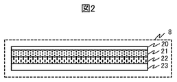
- FIG. 2 is a diagram illustrating an example of a cross-sectional structure of the display 8 including the liquid crystal panel 22 and the touch panel 21.
- the touch panel 21 is arranged on the upper surface of the liquid crystal panel 22 to integrate them
- the protective cover 20 such as glass is arranged on the upper surface of the touch panel 21
- the backlight 23 is arranged on the lower surface of the liquid crystal panel 22.
- the touch panel 21 is of a capacitive type, for example, and transparent electrodes are arranged in a two-dimensional shape orthogonal to each other.
- a human finger or touch pen touches or approaches the display screen of the display 8
- the capacitance between the finger or touch pen and the transparent electrode changes, and the horizontal and vertical positions on the touched screen are detected.
- the display and operation of the display 8 including the touch panel 21 will be described later.
- the detection accuracy is improved by arranging the touch panel 21 so as to be in close contact with the protective cover 20.
- the glossy finish on the surface of the protective cover 20 increases the clarity of the display image on the liquid crystal panel 22 and improves sliding of the finger and the touch pen.
- the surface of the protective cover 20 has a gloss finish, the amount of reflection of light from the outside increases.
- the backlight 23 emits illumination light from the back surface of the liquid crystal panel 22 to display an image.
- the backlight 23 is controlled to be turned off to reduce power consumption.
- the backlight 23 may be turned off for the entire display 8, or the backlight 23 may be divided into a plurality of parts and controlled, and a part of the display 8 may be turned off.
- a panel such as an organic EL may be used instead of the liquid crystal panel 22 and the backlight 23 .
- a display panel using a light emitting element such as an organic EL does not require a backlight.
- the touch panel 21 may use a pressure-sensitive method or the like in addition to the capacitance method.
- FIG. 3 is a diagram illustrating an example of the appearance of the mobile terminal 1
- FIG. 3A is a view of the mobile terminal 1 viewed from the back side
- FIG. 3B is a view of the mobile terminal 1 viewed from the side surface
- FIG. 3C is a diagram of the mobile terminal 1 as viewed from the front side.
- a display 8 in which a touch panel 21 is integrated is disposed on the back surface of the mobile terminal 1.
- the lens portion 2a of the rear camera is disposed on the front surface
- the lens portion 2b of the front camera is disposed on the rear surface.
- each of the lens portions 2a and 2b is a fixed type on the front and back surfaces.
- the lens units 2a and 2b may be detachable and interchangeable with lenses having different focal lengths.
- the power switch 33 is a switch that is operated when the portable terminal 1 is activated and terminated.
- the portable terminal 1 may have a power saving mode, and may also be used as a switch for returning to the power saving mode.
- the speaker 32 and the microphone 34 are for, for example, a telephone call, they are arranged so as to be close to the caller's ear and mouth during a telephone call.
- the proximity sensor 31 is disposed near the speaker 32 in order to detect, for example, the approach of the face during a call, and the infrared proximity sensor includes a near infrared light emitting part and a light receiving part. As will be described later, the proximity sensor 31 is disposed on the same surface as the display 8, that is, the back surface, in order to detect the attachment of the viewer.
- a speaker 32 and a microphone 34 are also arranged on the back side.
- the shutter 35 is a switch for instructing photographing through the lens unit 2a, and may coexist with a shutter by touching a part of the touch panel 21, or the shutter 35 may not be provided.
- the example of FIG. 3B is an example of the arrangement of the power switch 33 and the shutter 35, and is not limited to this arrangement.
- FIG. 4 is a diagram illustrating an example of the viewer 40 attached to the mobile terminal 1.
- the viewer 40 has a structure that can be attached to and detached from the back surface of the mobile terminal 1.
- 4A is a view of the viewer 40 viewed from the back side
- FIG. 4B is a view of the viewer 40 viewed from the side
- FIG. 4C is a view of the viewer 40 viewed from the front side.
- the back surface, the side surface, and the front surface are the same surfaces as the portable terminal 1 shown in FIG. 3, and are not surfaces based on the structure of the viewer 40.
- the viewer 40 includes a finder unit 42a.
- the finder portion 42a has a shape in which four sides are surrounded by a rectangular tube, that is, a substantially rectangular light shielding plate, and blocks light from the side surface.
- the opening 41 of the finder part 42a is an opening that allows light from the front side to the back side of the viewer 40 to pass therethrough. This will be described later with reference to FIG.
- the cavity 43 is a cavity that allows light and a human finger or touch pen to pass between the front side and the back side of the viewer 40.
- the entire viewer 40 has a shape that is attached so as to cover a part of the back surface and side surface of the mobile terminal 1, and is a light shielding material, for example, a material such as colored polycarbonate.
- the viewer 40 and the portable terminal 1 may be shaped so as to maintain the wearing state by being sandwiched between fingers, or the viewer 40 and the portable terminal 1 have irregularities not shown, and the irregularities are fitted.
- the shape which maintains a mounting state by being done may be sufficient.
- the viewer 40 has a shape that is detected by the proximity sensor 31 in a state where the viewer 40 is mounted on the mobile terminal 1. For this reason, at the time of mounting, the opening 41 and the cavity 43 are not positioned to face the proximity sensor 31, and a part of the viewer 40 excluding the opening 41 and the cavity 43 is positioned to face the proximity sensor 31.
- FIG. 5 is a cross-sectional view showing an example of the finder portion 42a.
- the cover glass 50 and the lens 51 are fitted into the opening 41 of the finder portion 42a, and the side surfaces of the finder portion 42a serve as support members.
- the display 8 is directly viewed without the viewer 40, the display 8 is normally viewed from a distance of about 30 cm or more from the display 8, whereas when the viewer 40 is used, the display 8 is viewed while looking through the finder portion 42a. Therefore, the image displayed on the display 8 is enlarged by the lens 51 and adjusted so as to be in focus.
- the cover glass 50 protects the lens 51. It is preferable that the finder part 42a extends from the eyepiece position to the cover glass 50. A shape in which the cover glass 50 is shielded from external light by the side face of the finder part 42a and the human face looked into is preferable.
- FIG. 6A is a diagram showing an example of display when the viewer 40 is not attached
- FIG. 6B is a diagram showing an example of display when the viewer 40 is attached.
- the display on the display 8 is changed depending on whether or not the viewer 40 is attached, that is, whether or not the viewer 40 is used.
- the display 8 is directly viewed.
- a subject 67a is a display of the subject imaged by the imaging unit 3a.
- the imaging area 66a is preferably a display of a range captured by the imaging unit 3a, but may be a display of a part of the range with its surroundings clipped.
- the display of the subject 67a and the imaging region 66a may be reduced and displayed according to the ratio between the number of pixels of the imaging units 3a and 3b and the number of pixels of the display 8.
- the setting buttons 60 to 64 are displays of various setting buttons, and the shutter button 65 is a display of buttons serving as shutters.
- the setting button 60 is for switching between the front camera and the rear camera, the setting button 61 is for changing the ISO sensitivity, and the setting button 62 is for changing the aperture value. 63 is for changing the shutter speed, and the setting button 64 is for setting the flash.
- These setting buttons 60 to 64 are operation menus for setting the camera, and are displayed on the display 8 to detect that the position corresponding to the display on the touch panel 21 of the operation input unit 9 is touched. Then, the setting is changed by the processing of the control circuit 6. For example, each time the setting button 60 is touched, the rear camera and the front camera are switched. Further, when the setting button 61 is touched, selectable ISO sensitivity is displayed by horizontal scrolling, and when selected by touching, the ISO sensitivity is changed. The aperture value of the setting button 62 and the shutter speed of the setting button 63 operate similarly to the setting button 61. Each time the setting button 64 is touched, ON (forced light emission), OFF (light emission inhibition), and automatic light emission (light emission control according to brightness) are set.
- These setting buttons 60 to 64 are examples of operation menus, and an arbitrary setting change menu and setting buttons such as a mode change to a shooting mode including moving image shooting and a playback mode, a focus mode, and a white balance are displayed. May be.
- the shutter button 65 has the same operation as the shutter 35 and may be used in combination.
- the video imaged by the imaging unit 3b as a front camera is displayed on the display 8, it is displayed as a mirror image, and the other images are usually displayed as normal images.
- 6A may be a general display or operation of a smartphone.
- the region 68 is a region corresponding to the hollow portion 43, and the region 68 can be directly viewed and touched through the hollow portion 43 even when the viewer 40 is attached.
- the display of the setting buttons 60 to 64 and the shutter button 65 in FIG. 6B is the same as the display example in FIG. 6A, but may be displayed smaller than the display in FIG.
- the setting button 60 for switching between the rear camera and the front camera may not be displayed using only the rear camera, or the setting button 60 may be grayed out and cannot be selected. . Further, when the attachment of the viewer 40 is detected, the setting buttons 60 to 64 may be changed to different operation menus.
- the subject 67b and the imaging region 66b correspond to the subject 67a and the imaging region 66a, respectively, and are displayed using the same video data as the imaging display by one operation of the shutter 35 and the shutter button 65.
- the subject 67a and the imaging region 66a are displayed at the same magnification
- the subject 67b and the imaging region 66b are displayed in a reduced size.
- the subject 67b and the imaging area 66b are displayed. This reduction is performed by the image / audio signal processing circuit 5.
- the size of the imaging region 66b is preferably a size that allows the image displayed in the imaging region 66b to be sufficiently confirmed from corner to corner by the enlargement of the lens 51.
- the reduction ratio to this size may be set by a touch operation, for example, by displaying a magnification setting button on the operation menu of the setting buttons 60 to 64. Further, the distance from the display 8 to the lens 51, the distance from the lens 51 to the eye to be looked into, the focal distance of the lens 51, etc. are preset, and the screen size and resolution of the display 8 are acquired, and the reduction magnification is obtained. It may be calculated.
- the display around the imaging region 66b that is, the hatched portion of the region 69 may be displayed with reduced brightness or black.
- the liquid crystal panel 22 may be controlled, or the backlight 23 may be controlled.
- the installation of the viewer 40 is detected by the proximity sensor 31.
- the control circuit 6 changes to the display shown in FIG. 6B. You may control. That is, the control circuit 6 may perform control so that the imaging area 66b including the subject 67b is reduced and displayed with the display luminance of the area 69 lowered.
- the removal of the viewer 40 is detected by the proximity sensor 31.
- the control circuit 6 changes to the display shown in FIG. 6A. You may control to do.
- a setting button for switching is also displayed on the operation menu of the setting buttons 60 to 64, and the display shown in FIG. 6A and the display shown in FIG. 6B may be controlled to be switched by a touch operation.
- the display 8 screen When shooting a still image or a moving image and the surroundings are bright, the display 8 screen may be difficult to see. In such a case, when the viewer 40 is attached, the light shielding property is improved, and the video of the subject 67b can be easily confirmed even in a bright place.
- FIG. 7A is a diagram showing an example of display including the focus setting area frame 70a when the viewer 40 is not attached.
- the same display as in FIG. In the display shown in FIG. 6A, for example, when the touch panel 21 detects that an arbitrary position in the display of the imaging region 66a is touched, the control circuit 6 sets the distance of the imaging target corresponding to the touched position. The focus is set and the focus setting area frame 70a is displayed.
- FIG. 7B is a diagram showing an example of display including the focus setting area frame 70b when the viewer 40 is attached.
- the touch pad area 71 is touched via the area 68 corresponding to the cavity 43, and moves the position of the focus setting area frame 70b in the imaging area 66b according to the touched position in the area 68. Then, the control circuit 6 controls.
- the position of the focus setting area frame 70b can be moved. Further, icons and the like corresponding to the setting buttons 60 to 64 shown in FIG. 7A are displayed in the display of the imaging region 66b, and the icons and the like are selected according to the position of the focus setting region frame 70b.
- the control circuit 6 may control.
- FIG. 8 is a diagram illustrating another example of the viewer 40.
- 8A is a view of the viewer 40 viewed from the back side
- FIG. 8B is a view of the viewer 40 viewed from the side
- FIG. 8C is a view of the viewer 40 viewed from the front side.
- the same structure as that of FIG. FIG. 8 differs from FIG. 4 in the shape of the finder part 42b.
- each of the side surfaces of the finder portion 42a is substantially rectangular, but in the example shown in FIG. 8, each of the side surfaces of the finder portion 42b is substantially trapezoidal. That is, the opening 41 becomes wider as it approaches the display 8. As a result, the area where the inner side of the finder portion 42b, that is, the inner surface on the opening 41 side can be seen when viewed, is reduced, and the display area of the imaging area 66b shown in FIGS. 6B and 7B is widened. In some cases, the number of pixels can be increased. Further, by making the side surface of the finder portion 42b substantially trapezoidal, the physical structural strength is also increased.
- the same function as that of the viewfinder can be obtained by simply mounting the viewer 40 on the portable terminal 1 that includes the display 8 such as a liquid crystal panel but does not include the electronic viewfinder.
- the effect is obtained.
- the viewer 40 does not include display parts unlike the electronic viewfinder, and the structure is simple and the cost is low.
- the viewer 40 can be substantially used. Since the display can be automatically switched between when the viewer 40 is attached and when the viewer 40 is not attached, an easy-to-use portable terminal can be provided. Furthermore, even if the viewer 40 is attached, the manual focus setting area frame can be moved.
- FIG. 9 is a block diagram illustrating an example of the configuration of the mobile terminal 1 according to the second embodiment.
- the same structure as that of FIG. 1 has two lens units 2a and 2b and two imaging units 3a and 3b corresponding to the front camera and the rear camera, whereas the example of FIG. 9 further includes a lens unit 2c and an imaging unit 3c. .
- the lens unit 2c and the imaging unit 3c are combined with the lens unit 2a and the imaging unit 3a so that the front camera can cope with stereo imaging and the like.
- the imaging unit 3 a and the imaging unit 3 b are controlled so as to capture images at the same timing, and the interface circuit 4 outputs both input signals from the imaging units 3 a and 3 c to the image / audio signal processing circuit 5.
- the image / audio signal processing circuit 5 generates video data for display of both input signals and outputs the video data to the display 8. This display will be described later.
- FIG. 10 is a diagram illustrating an example of the appearance of the mobile terminal 1 according to the second embodiment.
- 10A is a diagram of the mobile terminal 1 viewed from the back side
- FIG. 10B is a diagram of the mobile terminal 1 viewed from the side
- FIG. 10C is a diagram of the mobile terminal 1 viewed from the front side. It is.
- the lens unit 2a and the lens unit 2c are arranged in the vertical direction on the front surface of the mobile terminal 1 at a predetermined interval.
- the arrangement in the vertical direction is to support shooting with the mobile terminal 1 in the horizontal direction, and is not limited to this, but is preferably arranged in the long side direction of the display 8.
- FIG. 11 is a diagram illustrating an example of the viewer 80 according to the second embodiment.
- the viewer 40 has a structure that can be attached to and detached from the back surface of the mobile terminal 1. Although it is preferable to be attached to the portable terminal 1 shown in FIGS. 9 and 10 of the present embodiment, it is attached to the portable terminal 1 shown in FIGS. May be.
- the viewer 80 attached to the portable terminal 1 shown in FIGS. 9 and 10 of the present embodiment captures images corresponding to the right eye and the left eye at the same time with the two imaging units of the imaging unit 3a and the imaging unit 3c. Sometimes used.
- the viewer 80 is used for viewing 3D images during reproduction.
- 11A is a view of the viewer 80 viewed from the back side
- FIG. 11B is a view of the viewer 80 viewed from the side
- FIG. 11C is a view of the viewer 80 viewed from the front side.
- each of the finder portions 82a and 82c has a shape in which the side surfaces are surrounded by a rectangular tube, that is, a substantially rectangular light shielding plate, and blocks light from the side surfaces.
- the openings 81a and 81c of the finder portions 82a and 82c are openings that allow light from the front side to the back side of the viewer 80 to pass therethrough.
- the cavity 83 is a cavity that allows light and a human finger or touch pen to pass between the front side and the back side of the viewer 80.
- the finder unit 82a and the finder unit 82c are arranged on the back surface of the viewer 80 at predetermined intervals in the vertical direction. This corresponds to the arrangement of the lens units 2a and 2c shown in FIG. 10 (c), and when the mobile terminal 1 is photographed sideways, the finder unit 82a and the finder unit 82c are respectively left eye and right eye. It is an arrangement to look into. In order to increase the area of the openings 81a and 81c, it is preferable to arrange them side by side in the long side direction of the display 8.
- the structure of each of the finder portions 82a and 82c is as described with reference to FIG.
- the hollow portion 83 is shown in FIGS. 11A and 11C as an example in which the touch panel 21 is easily operated with the thumb when the portable terminal 1 is photographed sideways, but is not limited thereto. It is not a thing and it may be arrange
- FIG. 12A is a diagram showing an example of display of the shooting mode when the viewer 80 is attached.
- the display 8 displays imaging areas 91a and 91c, setting buttons 61 to 63, and a shutter button 65.
- the setting buttons 61 to 63 and the shutter button 65 are as described with reference to FIG. 6A.
- the setting buttons 61 to 63 and the shutter button 65 are displayed in an area 90 corresponding to the cavity 83.
- Each of the imaging area 91a and the imaging area 91c is a display of a range captured by the imaging unit 3a and the imaging unit 3c.
- the display of the imaging area 91a can be seen through the opening 81a and the imaging can be performed through the opening 81c.
- the area 91c is displayed at a position where it can be seen.
- the subject 94a and the subject 94c are the same as objects, they are captured by the image capturing unit 3a and the image capturing unit 3c, and thus are captured from different angles.
- the video data obtained by imaging by the imaging unit 3a is displayed in the imaging area 91a as the subject 94a, and the display of the subject 94a is viewed by the left eye through the finder unit 82a, and is captured by the imaging unit 3c.
- the video data obtained in this way is displayed as a subject 94c in the imaging area 91c, and the display of the subject 94c can be viewed with the right eye through the viewfinder unit 82c, so that it can be viewed as a 3D image.
- the display includes the imaging region 66a shown in FIG. 6A instead of the two displays of the imaging region 91a and the imaging region 91c. May be.
- video data obtained by imaging in either the imaging unit 3a or the imaging unit 3c may be displayed.
- the display of the imaging area 91a and the imaging area 91c may be smaller than the display of the imaging area 66a, and the display of the subject 94a and the subject 94c may be reduced smaller than the display of the subject 67a.
- the display size of the imaging area 91a and the imaging area 91c may be the same.
- the display of the viewer 80 may be detected by the proximity sensor 31 and the display screen may be switched.
- FIG. 12B is a diagram showing a display example of the playback mode when the viewer 80 is attached.
- the setting buttons 61 to 63 may be operation menus for reproduction. Alternatively, it may be a display of setting contents at the time of shooting the image to be reproduced.
- a recorded image selection button 95 displayed instead of the shutter button 65 is a display for input used to select an image to be reproduced.
- the display areas 93a and 93c are displays of images to be reproduced.
- subjects 94d and 94e are displayed in the same manner as the subjects 94a and 94c shown in FIG. 12A.
- the display areas 93a and 93c are displayed at the same positions as the imaging areas 91a and 91c. Accordingly, it can be viewed as a 3D image in the same manner as described with reference to FIG. 12A.
- the imaging regions 92a and 92c are displays of images captured by the imaging units 3a and 3c. Even in the reproduction mode, the imaging units 3a and 3c capture images, and the captured images are combined and displayed on a part of the display areas 93a and 93c in real time. When the viewer 80 is used during reproduction, the viewfinders 82a and 82c are shielded from light and the surroundings cannot be seen. It becomes possible to confirm the situation. This synthesis and superimposition may be performed by the image / audio signal processing circuit 5.
- the display of the imaging regions 92a and 92c in the playback mode may be switched on and off by a setting button or the like not shown.
- a reproduced image may be displayed in a superimposed manner on part of the imaging areas 91a and 91c.
- the viewer 80 Since the positional relationship between the lens units 2a and 2c, the portable terminal 1, and the viewer 80 attached to the portable terminal 1 is fixed, the viewer 80 looks in the direction in which the lens units 2a and 2c are directed in the shooting mode. It becomes. Even in the reproduction mode, as in this state, the display images of the display areas 93a and 93c may be changed according to the direction in which the lens units 2a and 2c are directed.
- the direction in which the lens units 2 a and 2 c are directed is also the direction of the viewer 80 and the portable terminal 1.
- the posture of the portable terminal 1 is detected by the posture detection unit 7, and the viewer 80 mounted on the portable terminal 1.
- the direction of peeking is specified.
- video data recorded in the shooting direction which is cut out in accordance with the direction in which the viewer 80 is directed, is extracted from the video data obtained by imaging at an ultra-wide angle. It may be displayed in the display areas 93a and 93c.
- Video data obtained by imaging at an ultra-wide angle may be obtained by imaging with the portable terminal 1 using the lenses 2a and 2c as ultra-wide-angle lenses, or images captured by other devices are captured. Also good. Further, for example, it is possible to view the image in the direction corresponding to the direction to which the viewer 80 is directed in 3D while reproducing the video data of a so-called all-sky image having an angle of view of 360 degrees and observing the image using the viewer 80. You can enjoy realistic images.
- the surroundings can be confirmed and the safety can be improved by displaying the images captured by the imaging units 3a and 3c superimposed on the reproduced image. .
- photographs with one of the imaging part 3a or the imaging part 3c of the portable terminal 1 shown to FIG. 9, 10 of a present Example and performs the display shown to FIG. 6A, 6B, 7A, 7B of Example 1.
- FIG. 4 and the viewer 80 shown in FIG. 11 may be selectively used according to one or both of the imaging unit 3a and the imaging unit 3b.
- the viewer 80 can view the shooting target as a 3D image when shooting the 3D image, and can also view the 3D image when reproducing the 3D image.
- the mobile terminal 1 includes a general-purpose device such as a tablet terminal or a smartphone having an imaging unit.
- a general-purpose device such as a tablet terminal or a smartphone having an imaging unit.
- the present invention mainly focuses on imaging such as a digital camera or a video camera. It can also be applied to an imaging device including a dedicated machine.
- the present invention it is possible to use a part of the display in the same manner as the electronic viewfinder by mounting the viewer on the portable terminal provided with the imaging unit. This makes it easy to monitor images even in bright outdoors.
- the display screen can be automatically switched between using the viewer and not using it. This makes it possible to provide a portable terminal and an imaging device that are easy to use.
Abstract
撮像部を正面側に備え、表示部とセンサを背面側に備える携帯端末であって、前記撮像部が出力する信号から前記表示部に表示させる情報を生成する信号処理部と、前記センサから信号を入力し、前記信号処理部を制御する制御部と、を有し、前記制御部の制御に基づく前記表示部の表示状態は、前記センサから検出の信号が入力されないと、第1の表示領域に表示される第1の表示状態と、前記センサから検出の信号が入力されると、第2の表示領域に表示される第2の表示状態と、を含む。
Description
本発明は、撮像部とディスプレイを備えた携帯端末に係わる。
撮像部(カメラ)を備えた従来の携帯端末は一般に通信機能を備え、カメラで撮影した画像を電話回線やネットワークを経由して外部に送信可能であり、ユーザー間による画像の共有等が容易にできるようになった。このような携帯端末は、通常、背面に液晶等のディスプレイを備えており、カメラで撮影するときには端末を手持ちし、一定の離れた距離からディスプレイ上に表示された撮影中の画像をモニタしながら撮影することができる。
このような携帯端末について、例えば特許文献1、2に開示されている。一方、デジタルカメラ等の撮像装置は、このようなディスプレイの他に、覗きこんで撮影画像を観察できる電子ビューファインダを備えた装置がある。電子ビューファインダについては、例えば特許文献3に開示されている。
しかし、特許文献1、2に開示された携帯端末は、屋外等の明るい環境ではディスプレイに外光が入射し、ディスプレイ上の画像が見難くなる課題があった。また、特許文献3に開示された電子ビューファインダは遮光しやすく屋外等の明るい環境でも画像のモニタが容易である反面、電子ビューファインダを備えた装置は小型化、薄型化が難しく、ディスプレイに加えて電子ビューファインダの電子部品のコストがかかるという課題があった。
そこで、本発明の目的は、ファインダ部を含むビューアを携帯端末で使用可能となるように携帯端末の表示を制御することにある。
上記課題を解決するために、本発明においては、例えば特許請求の範囲に記載の構成を採用する。その一例を挙げると、撮像部を正面側に備え、表示部とセンサを背面側に備える携帯端末であって、前記撮像部が出力する信号から前記表示部に表示させる情報を生成する信号処理部と、前記センサから信号を入力し、前記信号処理部を制御する制御部と、
を有し、前記制御部の制御に基づく前記表示部の表示状態は、前記センサから検出の信号が入力されないと、第1の表示領域に表示される第1の表示状態と、前記センサから検出の信号が入力されると、第2の表示領域に表示される第2の表示状態と、を含むことを特徴とする。
を有し、前記制御部の制御に基づく前記表示部の表示状態は、前記センサから検出の信号が入力されないと、第1の表示領域に表示される第1の表示状態と、前記センサから検出の信号が入力されると、第2の表示領域に表示される第2の表示状態と、を含むことを特徴とする。
本発明によれば、ファインダ部を含むビューアに適した表示が可能となり、ビューアを携帯端末で使用可能となる。
以下、本発明の実施形態について、図面を参照しながら説明する。
図1は、実施例1に係わる携帯端末1の構成の例を示すブロック図である。レンズ部2aと撮像部3aは、携帯端末1の正面に配置されたリアカメラであり、一般に風景等の通常の撮影に使用される。レンズ部2bと撮像部3bは、携帯端末1の背面に配置されたフロントカメラであり、いわゆる自撮りを行なうときに使用される。
レンズ部2a、2bは各々フォーカスレンズを含む複数枚のレンズから構成され、制御回路6によってフォーカスレンズの位置が制御されてフォーカシング動作を行う。撮像部3a、3bは、CMOSやCCD等により構成される撮像素子を含む。撮像部3a、3bの撮像面には撮像素子である光電変換素子が2次元状に配列されており、レンズ部2a、2bを介して入力し撮像面に結像された被写体の光学像を光電変換して撮像信号に変換する。
撮像部3a、3bには、アナログ信号をデジタル信号に変換するAD変換回路が内蔵されており、デジタル化された撮像信号を出力する。また、撮像部3a、3bは、位相差AF(オートフォーカス)用の画素が配置された撮像素子を含み、AFの高速化が図られてもよい。撮像部3a、3bはメモリを内蔵し、次の撮像までの間隔が短縮されてもよい。
なお、撮像部3a、3bがAD変換回路を内蔵していない場合には、AD変換回路が撮像部3a、3bの外部に設けられてもよい。撮像部3a、3bおよびレンズ部2a、2bは、フォーカシング動作以外に携帯端末1の動作モードに応じても制御回路6によって制御される。
インターフェース回路4は、携帯端末1の動作モードに応じて、撮像部3a、3bからの入力信号の一方または両方を画像音声信号処理回路5に出力する。この動作モードも制御回路6によって制御される。画像音声信号処理回路5は、インターフェース回路4からの入力信号に対し、フィルタリング、感度設定に応じた増幅、ホワイトバランス補正等の各種の画像信号処理を行う。
画像音声信号処理回路5は、画像信号処理された信号から、表示用の映像データあるいは記録用の映像データとして、動画データあるいは静止画データを動作モードに応じて生成する。ここで、表示用の映像データは、画像として拡大縮小されてもよい。表示用の映像データはディスプレイ8へ出力され、記録用の映像データは符号化復号化回路15へ出力される。
画像音声信号処理回路5は、符号化復号化回路15から符号化あるいは復号化された映像データを入力し、記録再生回路10へ出力してもよいし、表示用の映像データを生成してディスプレイ8へ出力してもよい。そして、画像音声信号処理回路5は、制御回路6の制御に応じて、文字や図形の画像データを生成し、ディスプレイ8へ出力してもよいし、ディスプレイ8の輝度を調整してもよい。
また、画像音声信号処理回路5は、画像信号処理を行う回路以外に音声信号処理を行う回路も備えており、マイク34からの入力信号に対し符号化等の所定の音声信号処理を行なう。そして、符号化された音声信号が入力されると復号化して、スピーカ32へ出力する。マイク34とスピーカ32は通話用であってもよく、音声信号が画像音声信号処理回路5と制御回路6を経由し、無線通信部14で電話回線に送受信されてもよい。
なお、画像音声信号処理回路5は、他の回路とワンチップ化されたLSIであってもよいし、1つの独立したLSIであってもよい。そして、撮像部3a、3bの性能に応じて、撮像部3a、3bのそれぞれを処理する2系統の回路を含み、同時に2系統の信号処理が行える回路であってもよい。また、DRAMやフラッシュメモリ等であるメモリ12を一時的なバッファメモリとして使用してもよい。
符号化復号化回路15は、動画データあるいは静止画データを符号化処理したり、符号化されたデータを復号化処理したりする。画像音声信号処理回路5の代わりに、音声信号を符号化処理したり、復号化処理したりしてもよい。記録再生回路10は、画像音声信号処理回路5から入力されたデータを記録媒体11に書き込んだり、記録媒体11に格納されたデータを読み出して、画像音声信号処理回路5へ出力したりする。なお、読み書きされるデータは、符号化されたデータであってもよい。
制御回路6は、姿勢検出部7、操作入力部9、位置情報入力部13、近接センサ31の各部から情報を入力し、レンズ部2a、2b、撮像部3a、3b、インターフェース回路4の各部を制御し、画像音声信号処理回路5および無線通信部14と情報を入出力する。また、制御回路6は、画像音声信号処理回路5および無線通信部14を制御してもよく、画像音声信号処理回路5を経由してディスプレイ8、符号化復号化回路15、記録再生回路10を制御してもよい。
さらに、図示を省略した制御線を用いて、制御回路6は、ディスプレイ8、符号化復号化回路15、記録再生回路10を直接的に制御してもよい。なお、制御回路6は、プロセッサであってもよく、図示を省略したメモリあるいはプロセッサに内蔵されたメモリに格納されるプログラムを実行してもよい。
無線通信部14は、無線通信によりインターネット等と通信する回路である。無線通信は電話回線や無線LAN等であってもよい。位置情報入力部13は、GPSや無線通信により携帯端末1の位置情報を取得し、取得された位置情報を制御回路6へ出力する回路である。姿勢検出部7は、加速度センサにより重力を検出したり、角速度センサにより回転を検出したりして、検出された情報を制御回路6へ出力する回路である。
近接センサ31は、携帯端末1に物体が接近したことを検出するセンサであり、通話のために携帯端末1に顔が近づいたことを主に検出するセンサである。本実施例の近接センサ31は、顔以外の接近も検出するため、人体ではない物体の接近も検出する赤外線型近接センサ等が好ましい。
操作入力部9は、ユーザーの操作入力を受け付けるものである。具体的には、後述するように、タッチパネルと電源ボタンとシャッターであるが、これらに限定されるものではなく、各種の専用ボタンを含んでもよい。ディスプレイ8は、例えば液晶パネルや有機ELパネル等の表示パネルである。ディスプレイ8と操作入力部9のタッチパネルは一体化したものが好ましく、以下では特に言及しない限り、操作入力部9のタッチパネルも含めてディスプレイ8と称する。
なお、携帯端末1は一般的なスマートフォンやタブレット等であってもよい。
携帯端末1の動作モードには少なくとも撮影モードと再生モードがある。まず、撮影モードの動作について説明する。操作入力部9(タッチパネル)が操作される等により撮影モードの起動指示を、制御回路6は検出して撮影モードに応じた制御を行う。撮影モードには、さらに静止画撮影モードと動画撮影モードがある。
静止画撮影あるいは動画撮影時のいずれにおいても、撮像部3a、3bは所定の周期で撮像信号を出力し、撮像信号は、インターフェース回路4を経て画像音声信号処理回路5にて所定の画像信号処理が行なわれ、表示用の映像データが生成される。表示用の映像データはディスプレイ8にリアルタイムで表示される。
このとき、AFや絞り値、撮像部3aと撮像部3bのいずれを使用するか等に応じて、制御回路6は、レンズ部2a、2b、撮像部3a、3b、インターフェース回路4、画像音声信号処理回路5等を制御する。なお、シャッターの押圧により半押しと全押しの2つの状態を検出するように設定されている場合、半押し状態を検出すると、制御回路6はAFの制御をするようにしてもよい。
静止画撮影モードにおいて、シャッターが押下された、または全押しされたことを検出すると、制御回路6はシャッター速度等の撮影条件に従って各部を制御する。そして、撮像部3a、3bによって撮像された静止画の撮像信号は、画像音声信号処理回路5によって所定の静止画信号処理が施された後、符号化復号化回路15によって符号化される。
ここで、静止画信号処理や符号化が行われる際に、バッファメモリとしてメモリ12が使用されてもよい。また、符号化は例えばJPEGデータへの符号化であってもよいし、MPEGデータの静止画への符号化であってもよい。符号化された静止画データは、画像音声信号処理回路5により記録再生回路10へ出力され、記録再生回路10により記録媒体11に記録される。なお、符号化復号化回路15が使用されず、高画質のRAW形式で記録されてもよい。
動画撮影モードにおいて、シャッターが押下された、または全押しされたことを検出すると、制御回路6は撮影条件に従って各部を制御する。動画撮影モードの場合、シャッターの押下が解除されても、制御回路6の撮影の制御は継続される。撮像部3a、3bによって撮像された動画の撮像信号は、画像音声信号処理回路5によって所定の動画信号処理が施された後、符号化復号化回路15によって符号化される。
符号化は例えばH.264やH.265等のMPEGデータへの符号化であってもよいし、その他の動画用フォーマットへの符号化であってもよい。符号化された動画データは、画像音声信号処理回路5により記録再生回路10へ出力され、記録再生回路10により記録媒体11に記録される。
動画を撮影中にシャッターが再び押下されたことを検出すると、制御回路6は撮影の制御を終了する。なお、動画の撮影中および撮影後も、画像音声信号処理回路5は表示用の映像データを生成し、表示用の映像データはディスプレイ8にリアルタイムで表示される。
次に、再生モードの動作について説明する。操作入力部9(タッチパネル)が操作される等により再生モードの起動指示を、制御回路6は検出して再生モードに応じた制御を行う。記録再生回路10は記録媒体11に記録されたデータの中から指定されたデータを読み出し、読み出されたデータは画像音声信号処理回路5を経由して符号化復号化回路15によって復号化され、復号化されたデータは画像音声信号処理回路5に出力される。画像音声信号処理回路5は復号化されたデータから表示用の映像データを生成し、表示用の映像データはディスプレイ8に表示される。
図2は、液晶パネル22とタッチパネル21を含むディスプレイ8の断面構造の一例を示す図である。ディスプレイ8は、タッチパネル21を液晶パネル22の上面に配置して両者を一体化し、タッチパネル21の上面にガラス等の保護カバー20を配置して、液晶パネル22の下面にバックライト23を配置している。
タッチパネル21は例えば静電容量方式のものであり、透明電極が直交する2次元状に配列されている。人間の指やタッチペンがディスプレイ8の表示画面に接触あるいは接近すると、指やタッチペンと透明電極間の静電容量が変化し、接触した画面上の水平、垂直方向の位置を検出する。なお、タッチパネル21を含むディスプレイ8の表示と操作に関しては、後述する。
この構造では、保護カバー20を介して静電容量を検出するので、タッチパネル21を保護カバー20に密着させるように配置することで検出精度が高まる。また、保護カバー20の表面を光沢仕上げとすることにより、液晶パネル22の表示画像の鮮明度が高まるとともに、指やタッチペンのすべりがよくなる。しかしながら、保護カバー20の表面を光沢仕上げとすると、外部からの光の反射量が増えてしまう。
バックライト23は液晶パネル22の背面から照明光を照射して画像を表示させるものである。表示の必要のない場合には、消費電力低減のためバックライト23を消灯するように制御される。バックライト23の消灯は、ディスプレイ8全体の消灯であってもよいし、バックライト23は複数の部分に分割されて制御され、ディスプレイ8の一部の消灯であってもよい。
なお、液晶パネル22とバックライト23の代わりに、有機EL等のパネルであってもよい。有機EL等の発光素子を用いる表示パネルでは、バックライトは不要である。また、タッチパネル21は、静電容量方式の他に感圧方式等を用いたものであってもよい。
図3は携帯端末1の外観の例を示す図であり、図3(a)は携帯端末1を背面側から見た図、図3(b)は携帯端末1を側面側から見た図、図3(c)は携帯端末1を正面側から見た図である。携帯端末1の背面にタッチパネル21の一体化されたディスプレイ8が配置されている。
図3(a)、(c)に示すように、リアカメラのレンズ部2aは正面に配置され、フロントカメラのレンズ部2bは背面に配置される。図3(a)、(c)で、レンズ部2a、2bのそれぞれは正面と背面の面上の固定式の例を示したが、着脱式として焦点距離の異なるレンズと交換可能としてもよい。電源スイッチ33は、携帯端末1の起動および終了時に操作されるスイッチであり、携帯端末1が省電力モードを有し、省電力モードの復帰用のスイッチとして兼用されてもよい。
スピーカ32とマイク34は例えば通話用であるため、通話時に通話者の耳と口の近くになるように配置されている。近接センサ31は、例えば通話時の顔の接近を検出するため、スピーカ32の近くに配置されており、赤外線型近接センサでは近赤外光の発光部と受光部を備える。近接センサ31は、後述するようにビューアの装着を検出するため、ディスプレイ8と同じ面すなわち背面に配置される。スピーカ32とマイク34も背面に配置される。
シャッター35はレンズ部2aを通しての撮影を指示するスイッチであり、タッチパネル21の一部のタッチによるシャッターと共存してもよいし、シャッター35は無くてもよい。図3(b)の例は、電源スイッチ33とシャッター35の配置の一例であり、この配置に限定されるものではない。
図4は携帯端末1に装着されるビューア40の例を示す図である。ビューア40は携帯端末1の背面に着脱可能な構造である。図4(a)はビューア40を背面側から見た図、図4(b)はビューア40を側面側から見た図、図4(c)はビューア40を正面側から見た図である。ここで、背面、側面、正面は、図3に示した携帯端末1と同じ面にしており、ビューア40の構造に基づく面ではない。
ビューア40はファインダ部42aを含む。ファインダ部42aは、図4(a)、(b)で示すように、角筒すなわち略長方形の遮光板に側面四方が囲まれた形状であり、側面からの光を遮断する。図4(a)、(c)で示すように、ファインダ部42aの開口部41は、ビューア40の正面側から背面側への光を通過させる開口部であり、開口部41内の構造は、図5を用いて後述する。空洞部43は、ビューア40の正面側と背面側との間で、光と人間の指やタッチペンを通過させる空洞である。
ビューア40全体は、携帯端末1の背面および側面の一部を覆うように装着される形状であり、遮光する材料であって、例えば着色されたポリカーポネート等の材料でできている。ビューア40と携帯端末1とは指で挟まれることにより、装着状態を維持する形状であってもよいし、ビューア40と携帯端末1のそれぞれが図示を省略した凹凸を有し、凹凸が嵌合されることにより装着状態を維持する形状であってもよい。
また、ビューア40は、ビューア40が携帯端末1に装着された状態で、近接センサ31により検出される形状である。このため、装着時に、開口部41と空洞部43は近接センサ31と対面する位置にはなく、開口部41と空洞部43を除くビューア40の一部が近接センサ31との対面に位置する。
図5はファインダ部42aの例を示す断面図である。ファインダ部42aの開口部41にはカバーガラス50とレンズ51がはまり、ファインダ部42aの側面がこれらの支持部材となる。ビューア40無しでディスプレイ8が直接目視される場合は、ディスプレイ8から30cm程度以上の距離から通常目視されるのに対し、ビューア40を用いる場合には、ファインダ部42aを覗き込んだ状態でディスプレイ8が目視されるため、レンズ51によりディスプレイ8に表示された画像を拡大してピントが合うように調整する。
カバーガラス50はレンズ51を保護するものである。接眼される位置からカバーガラス50までは、ファインダ部42aが伸びていることが好ましく、ファインダ部42aの側面と覗き込んだ人間の顔により、外光からカバーガラス50が遮光される形状が好ましい。
図6Aはビューア40が装着されていない場合の表示の例を示す図であり、図6Bはビューア40が装着されている場合の表示の例を示す図である。ディスプレイ8の表示は、ビューア40が装着されているか否か、すなわちビューア40が用いられるか否かに応じて変更される。図6Aのビューア40が用いられない場合は、ディスプレイ8が直視される。
図6Aにおいて、被写体67aは撮像部3aにより撮像された被写体の表示である。撮像領域66aは撮像部3aにより撮像された範囲の表示であることが好ましいが、周囲がクリッピングされて一部の範囲の表示であってもよい。また、被写体67aおよび撮像領域66aの表示は、撮像部3a、3bの画素数とディスプレイ8の画素数との比に応じて縮小されて表示されてもよい。
設定ボタン60~64は各種の設定ボタンの表示であり、シャッターボタン65はシャッターとなるボタンの表示である。設定ボタン60はフロントカメラとリアカメラの切り替えのためのものであり、設定ボタン61はISO感度の変更のためのものであり、設定ボタン62は絞り値の変更のためのものであり、設定ボタン63はシャッター速度の変更のためのものであり、設定ボタン64はフラッシュの設定のためのものである。
これらの設定ボタン60~64は、カメラの設定のための操作メニューであり、ディスプレイ8に表示されて、操作入力部9のタッチパネル21のおける、表示に対応する位置のタッチされたことが検出されると、制御回路6の処理により、設定が変更される。例えば、設定ボタン60はタッチされる毎にリアカメラとフロントカメラが切り替わる。
また、設定ボタン61がタッチされると、横スクロールにより選択可能なISO感度が表示され、タッチにより選択されるとISO感度が変更される。設定ボタン62の絞り値と設定ボタン63のシャッター速度も設定ボタン61と同様に動作する。設定ボタン64は、タッチされる毎にオン(強制発光)、オフ(発光禁止)、自動発光(明るさに応じ発光制御)が設定される。
また、設定ボタン61がタッチされると、横スクロールにより選択可能なISO感度が表示され、タッチにより選択されるとISO感度が変更される。設定ボタン62の絞り値と設定ボタン63のシャッター速度も設定ボタン61と同様に動作する。設定ボタン64は、タッチされる毎にオン(強制発光)、オフ(発光禁止)、自動発光(明るさに応じ発光制御)が設定される。
なお、これらの設定ボタン60~64は操作メニューの一例であって、動画撮影を含む撮影モードや再生モードへのモード変更、フォーカスモード、ホワイトバランス等々、任意の設定変更メニューや設定ボタンが表示されてもよい。シャッターボタン65はシャッター35と同じ動作であって、併用されるものであってもよい。
また、フロントカメラとして撮像部3bで撮像した映像をディスプレイ8で表示する際には鏡像として表示し、その他の画像は通常正像として表示する。そして、図6Aの表示や動作はスマートフォンの一般的な表示や動作であってもよい。
図6Bの表示で、図6Aと同じ表示は同じ符号を付して、説明を省略する。領域68は空洞部43に対応する領域であり、ビューア40が装着された状態であっても、空洞部43を介して、領域68は直視できるとともに、タッチされることも可能である。図6Bの設定ボタン60~64とシャッターボタン65の表示は、図6Aと同じ表示の例を示したが、領域68に収まるように図6Aの表示より縮小されて表示されてもよい。
ビューア40が装着された場合は、リアカメラのみを用いて、リアカメラとフロントカメラの切り替えの設定ボタン60は表示されなくてもよいし、設定ボタン60がグレーアウトされて選択できないようにしてもよい。また、ビューア40の装着が検出された場合に、設定ボタン60~64は異なる操作メニューに変更されてもよい。
被写体67bと撮像領域66bは、それぞれ被写体67aと撮像領域66aに対応し、シャッター35やシャッターボタン65の1回の操作による撮像の表示としては、同じ映像データが用いられて表示される。ここで、被写体67aと撮像領域66aが等倍表示の場合は、被写体67bと撮像領域66bが縮小されて表示され、被写体67aと撮像領域66aが縮小表示の場合は、その縮小表示よりも小さく縮小されて被写体67bと撮像領域66bが表示される。この縮小は画像音声信号処理回路5により行われる。
撮像領域66bの大きさは、レンズ51の拡大により、撮像領域66bに表示された画像を隅から隅まで十分に確認可能な大きさが好ましい。この大きさへの縮小の倍率は、例えば設定ボタン60~64の操作メニューに倍率の設定ボタンも表示され、タッチ操作により設定されてもよい。また、ディスプレイ8からレンズ51までの距離、レンズ51から覗き込まれる目までの距離、レンズ51の焦点距離等が予め設定され、ディスプレイ8の画面サイズと解像度等を取得して、縮小の倍率が計算されてもよい。
撮像領域66bの周囲の表示すなわち領域69のハッチング部分の表示は、輝度を下げた表示にしてもよいし、黒の表示にしてもよい。この表示のために液晶パネル22が制御されてもよいし、バックライト23が制御されてもよい。
ビューア40の装着は、近接センサ31で検出される。例えば、撮影モードに設定された状態で近接センサ31が予め設定された距離の範囲に予め設定された時間より長く近接物を検出すると、制御回路6は、図6Bに示した表示に変更するよう制御してもよい。すなわち、制御回路6は、被写体67bを含む撮像領域66bを縮小し、領域69の表示の輝度を下げて表示するように制御してもよい。
また、ビューア40の取り外しも、近接センサ31で検出される。例えば、撮影モードに設定された状態で近接センサ31が予め設定された距離の範囲に予め設定された時間より長く近接物を検出しなくなると、制御回路6は、図6Aに示した表示に変更するよう制御してもよい。なお、設定ボタン60~64の操作メニューに切り替えの設定ボタンも表示され、タッチ操作により、図6Aに示した表示と図6Bに示した表示とが切り替えられるように制御されてもよい。
静止画や動画の撮影時で、周囲が明るいときには、ディスプレイ8の画面が見にくいことがある。このような場合にビューア40が装着されることで遮光性がよくなり、周囲が明るいところでも被写体67bの映像の確認が容易となる。
図7Aはビューア40が装着されていない場合のフォーカス設定領域枠70aを含む表示の例を示す図である。図7Aの表示で、図6Aと同じ表示は同じ符号を付して、説明を省略する。図6Aに示した表示において、例えば撮像領域66aの表示の中の任意の位置がタッチされたことをタッチパネル21が検出すると、制御回路6は、そのタッチされた位置に相当する撮像対象の距離にフォーカスを合わせて、フォーカス設定領域枠70aを表示する。
図7Bはビューア40が装着されている場合のフォーカス設定領域枠70bを含む表示の例を示す図である。図7Bの表示で、図6Bと同じ表示は同じ符号を付して、説明を省略する。タッチパッド領域71は、空洞部43に対応する領域68を介してタッチされ、領域68の中のタッチされた位置に応じて、撮像領域66bの中のフォーカス設定領域枠70bの位置を移動するように、制御回路6が制御する。
これにより、撮像領域66bの表示はビューア40の装着によりカバーガラス50でタッチできなくても、フォーカス設定領域枠70bの位置を移動することができる。また、図7Aに示した設定ボタン60~64に相当するアイコン等を、撮像領域66bの表示の中に表示して、フォーカス設定領域枠70bの位置に応じてアイコン等が選択されるように、制御回路6は制御してもよい。
図8はビューア40の別の例を示す図である。図8(a)はビューア40を背面側から見た図、図8(b)はビューア40を側面側から見た図、図8(c)はビューア40を正面側から見た図である。図8において図4と同じ構造には同じ符号を付して説明を省略する。図4と比較して図8は、ファインダ部42bの形状が異なる。
図4に示した例では、ファインダ部42aの側面のそれぞれは略長方形であったが、図8に示した例では、ファインダ部42bの側面のそれぞれは略台形である。すなわち、開口部41がディスプレイ8に近づくほど広くなる。これにより、覗き込んだ際に、ファインダ部42bの内側すなわち開口部41側の内側面の見える領域が減り、図6Bと図7Bに示した撮像領域66bの表示領域を広くし、表示領域内の画素数が増やすことのできる場合がある。また、ファインダ部42bの側面を略台形とすることにより、物理的な構造上の強度も増す。
以上で説明したように、本実施例によれば、液晶パネル等のディスプレイ8を備えているが電子ビューファインダを備えていない携帯端末1において、ビューア40を装着するだけでビューファインダと同様の機能、効果が得られる。ここで、ビューア40には電子ビューファインダのように表示部品が含まれず、構造は単純であってコストが低い。
また、ビューア40の装着により発生する撮像領域66aの表示の確認できない部分を携帯端末1の画像処理により無くすことができるため、ビューア40を実質的に使用可能とすることができる。そして、ビューア40の装着時と非装着時に表示を自動的に切り替えることができるので、使い勝手の良い携帯端末を提供することができる。さらに、ビューア40を装着しても、手動のフォーカス設定領域枠の移動が可能となる。
実施例1ではリアカメラが1個の例を説明したが、実施例2ではリアカメラが2個の例を説明する。図9は実施例2の携帯端末1の構成の例を示すブロック図である。図9において、図1と同じ構造は同じ符号を付して、説明を省略する。図1ではフロントカメラとリアカメラに対応する2つのレンズ部2a、2bと2つの撮像部3a、3bを有していたのに対し、図9の例ではレンズ部2cと撮像部3cをさらに有する。
レンズ部2cおよび撮像部3cは、レンズ部2aおよび撮像部3aと組み合わされて、フロントカメラをステレオ撮像などに対応できるようにするものである。例えば、撮像部3aと撮像部3bとは同じタイミングで撮像するように制御され、インターフェース回路4は、撮像部3a、3cからの入力信号の両方を画像音声信号処理回路5に出力する。また、画像音声信号処理回路5は、両方の入力信号の表示用の映像データを生成し、ディスプレイ8へ出力する。この表示については、後述する。
図10は実施例2の携帯端末1の外観の例を示す図である。図10(a)は携帯端末1を背面側から見た図、図10(b)は携帯端末1を側面側から見た図、図10(c)は携帯端末1を正面側から見た図である。図10で図3と同じ構造は同じ符号を付して、説明を省略する。図3ではリアカメラのレンズ部2aを有したが、図10の例ではリアカメラのレンズ部2aとレンズ部2cを有する。
レンズ部2aとレンズ部2cとは携帯端末1の正面に縦方向に所定間隔で配置される。なお、縦方向の配置は、携帯端末1を横向きにしての撮影に対応するためであり、これに限定されるものではないが、ディスプレイ8の長辺方向に並べて配置されることが好ましい。
図11は実施例2のビューア80の例を示す図である。ビューア40は携帯端末1の背面に着脱可能な構造である。なお、本実施例の図9、10に示した携帯端末1に装着されることが好ましいが、実施例1の図1、3に示した携帯端末1に装着され、3D画像の再生表示時に使用されてもよい。
本実施例の図9、10に示した携帯端末1に装着されたビューア80は、撮像部3a、撮像部3cの2つの撮像部で右眼と左眼に対応する画像を同時に撮影する3D撮影時に用いられる。また再生時にこのビューア80を用いて3D画像の観賞に用いられる。図11(a)はビューア80を背面側から見た図、図11(b)はビューア80を側面側から見た図、図11(c)はビューア80を正面側から見た図である。
ファインダ部82a、82cのそれぞれは、図11(a)、(b)に示すように、角筒すなわち略長方形の遮光板に側面四方が囲まれた形状であり、側面からの光を遮断する。また、ファインダ部82a、82cそれぞれの開口部81a、81cは、ビューア80の正面側から背面側への光を通過させる開口部である。空洞部83は、ビューア80の正面側と背面側との間で、光と人間の指やタッチペンを通過させる空洞である。
ファインダ部82aとファインダ部82cはビューア80の背面に縦方向に所定間隔で配置される。これは、図10(c)に示したレンズ部2a、2cの配置に対応し、携帯端末1を横向きにして撮影するときに、ファインダ部82aとファインダ部82cのそれぞれは左眼と右眼で覗き込まれる配置である。なお、開口部81a、81cの面積を大きくするために、ディスプレイ8の長辺方向に並べて配置されることが好ましい。ファインダ部82a、82cそれぞれの構造は、図5を用いて説明したとおりである。
空洞部83は、携帯端末1を横向きにして撮影するときに、親指でタッチパネル21を操作しやすい位置に配置された例を図11(a)、(c)に示したが、これに限定されるものではなく、ファインダ部82a、82c以外の操作しやすい位置であれば、どこに配置されてもよい。ただし、開口部81a、81cと空洞部83以外のビューア80の一部が、装着時に近接センサ31で検出されるように、開口部81a、81cと空洞部83は配置されることが好ましい。
図12Aはビューア80が装着されている場合の撮影モードの表示の例を示す図である。ディスプレイ8には、撮像領域91a、91c、設定ボタン61~63、シャッターボタン65が表示されるが、設定ボタン61~63とシャッターボタン65は図6Aを用いて説明したとおりである。そして、設定ボタン61~63とシャッターボタン65は、空洞部83に対応する領域90に表示される。
撮像領域91aと撮像領域91cそれぞれは、撮像部3aと撮像部3cで撮像された範囲の表示であり、ビューア80の装着時に、開口部81aを通して撮像領域91aの表示が見え、開口部81cを通して撮像領域91cの表示が見える位置に表示される。被写体94aと被写体94cは物としては同一であるが、撮像部3aと撮像部3cにより撮像されたため、角度の異なる位置からの撮像の表示となる。
そして、撮像部3aで撮像されて得られた映像データが、被写体94aとして撮像領域91a内に表示され、ファインダ部82aを介して被写体94aの表示を左眼で見て、撮像部3cで撮像されて得られた映像データが、被写体94cとして撮像領域91c内に表示され、ファインダ部82cを介して被写体94cの表示を右眼で見ることにより、3D画像として見ることができる。
なお、撮影モード時にビューア80が装着されていない場合、3D画像として見ることはできないため、撮像領域91aと撮像領域91cの2つの表示ではなく、図6Aに示した撮像領域66aを含む表示であってもよい。撮像領域66aを表示するために、撮像部3aまたは撮像部3cのいずれか一方の撮像部での撮像により得られた映像データが表示されてもよい。
撮像領域91aと撮像領域91cそれぞれの表示は、撮像領域66aの表示より小さく、被写体94aと被写体94cのそれぞれの表示は、被写体67aの表示より小さく縮小されてもよい。撮像領域91aと撮像領域91cの表示サイズは同じであってもよい。また、ビューア80の装着は近接センサ31により検出されて、表示画面が切り替えられてもよい。
図12Bはビューア80が装着されている場合の再生モードの表示の例を示す図である。図12Bの表示で図12Aと同じ表示は同じ符号を付して説明を省略する。ただし、設定ボタン61~63は再生のための操作メニューであってもよい。あるいは、再生される画像の撮影時の設定内容の表示であってもよい。シャッターボタン65の代わりに表示される記録画像の選択ボタン95は、再生される画像の選択に使用される入力のための表示である。
表示領域93a、93cは再生される画像の表示であり、図12Aに示した表示の状態で撮像した場合、図12Aに示した被写体94a、94cと同じように、被写体94d、94eが表示される。また、表示領域93a、93cは撮像領域91a、91cと同じ位置に表示される。これにより、図12Aを用いて説明したのと同じように3D画像として見ることができる。
撮像領域92a、92cは、撮像部3a、3cで撮像した画像の表示である。再生モードにおいても撮像部3a、3cが撮像し、撮像された画像をリアルタイムで表示領域93a、93cの一部に合成して表示する。再生時にビューア80を使用するとファインダ部82a、82cにより遮光されて周囲が見えないが、表示領域93a、93cとともに撮像領域92a、92cが重畳表示されることで、3D再生画像を鑑賞しつつ、周囲の状況を確認することが可能となる。この合成、重畳は画像音声信号処理回路5により行われてもよい。
なお、再生モードにおける撮像領域92a、92cの表示は、図示を省略した設定ボタン等によりオンオフが切り替えられてもよい。また、撮影モードにおいて、撮像領域91a、91cの一部に再生画像を重畳表示してもよい。
レンズ部2a、2c、携帯端末1、携帯端末1に装着されたビューア80は、位置関係が固定されるため、撮影モードでは、レンズ部2a、2cの向けられた方向をビューア80で覗き見る状態となる。再生モードでも、この状態と同じように、レンズ部2a、2cの向けられた方向に応じて表示領域93a、93cの表示画像が変更されてもよい。
ここで、レンズ部2a、2cが向けられた方向は、ビューア80および携帯端末1の方向でもあり、姿勢検出部7により携帯端末1の姿勢が検出され、携帯端末1に装着されたビューア80の覗き見る方向が特定される。そして、例えば、撮影方向の記録された映像データであって、超広角で撮像されて得られた映像データの中から、ビューア80が向けられた方向に応じて画像を切り出し、切り出された画像が表示領域93a、93cに表示されてもよい。
超広角で撮像されて得られる映像データは、レンズ部2a、2cを超広角のレンズとして、携帯端末1で撮像されて得られてもよいし、他の装置で撮像された画像が取り込まれてもよい。また、例えば360度の画角を有する所謂全天空型の画像の映像データを再生し、ビューア80を用いて観察しながら、ビューア80を向けた方向に対応する方向の画像を3Dで見ることができ、臨場感のある映像を楽しむことができる。
なお、この場合にも、図12Bを用いて説明したように、撮像部3a、3cが撮像した画像を再生画像に重畳表示することで、周囲の状況を確認でき、安全性を高めることができる。また、本実施例の図9、10に示した携帯端末1の撮像部3aか撮像部3cの一方で撮像し、実施例1の図6A、6B、7A、7Bに示した表示を行ってもよく、撮像部3aと撮像部3bの一方か両方かに応じて、図4に示したビューア40と図11に示したビューア80が使い分けられてもよい。
以上で説明したように、実施例2によれば、ビューア80により、3D画像の撮影において3D画像で撮影対象を見ることができ、3D画像の再生においても3D画像を見ることができる。特に、2個の電子ビューファインダを備える必要がなく、単純な構造で低コストのビューア80を用いることが可能となる。
なお、実施例1、2において、携帯端末1とは、撮像部を有するタブレット端末やスマートフォン等の汎用機を含むものであるが、本発明はこれらのほかにデジタルカメラやビデオカメラ等、撮像を主とする専用機を含む撮像装置に適用することもできる。
本発明によれば、撮像部を備えた携帯端末にビューアを装着することにより、ディスプレイの一部を電子ビューファインダと同様に使用することができる。このため、明るい屋外でも画像のモニタが容易となる。また、ビューア使用時と非使用時とで表示画面を自動的に切り換えることができる。これによって使い勝手のよい携帯端末、撮像装置を提供することができる。
1:携帯端末
2a、2b、2c:レンズ部
3a、3b、3c:撮像部
4:インターフェース回路
8:ディスプレイ
31:近接センサ
40、80:ビューア
42a、42b、82a、82c:ファインダ部
43、83:空洞部
2a、2b、2c:レンズ部
3a、3b、3c:撮像部
4:インターフェース回路
8:ディスプレイ
31:近接センサ
40、80:ビューア
42a、42b、82a、82c:ファインダ部
43、83:空洞部
Claims (15)
- 撮像部を正面側に備え、表示部とセンサを背面側に備える携帯端末であって、
前記撮像部が出力する信号から前記表示部に表示させる情報を生成する信号処理部と、
前記センサから信号を入力し、前記信号処理部を制御する制御部と、
を有し、
前記制御部の制御に基づく前記表示部の表示状態は、
前記センサから検出の信号が入力されないと、第1の表示領域に表示される第1の表示状態と、
前記センサから検出の信号が入力されると、第2の表示領域に表示される第2の表示状態と、
を含むことを特徴とする携帯端末。 - 請求項1に記載の携帯端末であって、
前記センサは近接センサであり、
前記制御部は、
前記センサに近接する物体がないと、前記センサから検出の信号が入力されず、
前記センサに近接する物体があると、前記センサから検出の信号が入力されること
を特徴とする携帯端末。 - 請求項1に記載の携帯端末であって、
前記第2の表示領域は前記第1の表示領域より小さいこと
を特徴とする携帯端末。 - 請求項3に記載の携帯端末であって、
前記第2の表示領域の周囲は表示輝度が低いこと
を特徴とする携帯端末。 - 請求項4に記載の携帯端末であって、
前記制御部は、
前記第2の表示領域に表示される画像が、前記第1の表示領域に表示される画像より小さく縮小するように前記信号処理部を制御すること
を特徴とする携帯端末。 - 請求項5に記載の携帯端末であって、
前記表示部は、
タッチパネルと一体化された表示部であって、
前記第1の表示領域の外に設定ボタンを表示し、
前記第1の表示領域の中においてタッチパネルにより検出されるタッチに応じたフォーカス設定領域枠を表示し、
前記タッチパネルは、
表示された設定ボタンの位置のタッチを検出すること
を特徴とする携帯端末。 - 請求項6に記載の携帯端末であって、
前記タッチパネルは、
前記第2の表示領域の外の位置のタッチを検出し、
前記表示部は、
前記第2の表示領域の外の位置で検出されたタッチに応じて、前記第2の表示領域の中にフォーカス設定領域枠を表示すること
を特徴とする携帯端末。 - 第1の撮像部と第2の撮像部を正面側に備え、表示部とセンサを背面側に備える携帯端末であって、
前記第1の撮像部および/または前記第2の撮像部が出力する信号から前記表示部に表示される情報を生成する信号処理部と、
前記センサから信号を入力し、前記信号処理部を制御する制御部と、
を有し、
前記制御部の制御に基づく前記表示部の表示状態は、
前記センサから検出の信号が入力されないと、第1の表示領域に表示される第1の表示状態と、
前記センサから検出の信号が入力されると、第2の表示領域と第3の表示領域に表示される第2の表示状態と、
を含むことを特徴とする携帯端末。 - 請求項8に記載の携帯端末であって、
前記センサは近接センサであり、
前記制御部は、
前記センサに近接する物体がないと、前記センサから検出の信号が入力されず、
前記センサに近接する物体があると、前記センサから検出の信号が入力されること
を特徴とする携帯端末。 - 請求項8に記載の携帯端末であって、
前記信号処理部は、
前記第1の撮像部または前記第2の撮像部が出力する信号から前記第1の表示領域に表示される情報を生成すること
を特徴とする携帯端末。 - 請求項10に記載の携帯端末であって、
前記信号処理部は、
前記第1の撮像部が出力する信号から前記第2の表示領域に表示される情報を生成し、
前記第2の撮像部が出力する信号から前記第3の表示領域に表示される情報を生成すること
を特徴とする携帯端末。 - 請求項8に記載の携帯端末であって、
前記第2の表示領域と前記第3の表示領域は、前記第1の表示領域より小さいこと
を特徴とする携帯端末。 - 請求項12に記載の携帯端末であって、
前記制御部は、
前記第2の表示領域と前記第3の表示領域に表示される画像が、前記第1の表示領域に表示される画像より小さく縮小するように前記信号処理部を制御すること
を特徴とする携帯端末。 - 請求項13に記載の携帯端末であって、
前記表示部は、
タッチパネルと一体化された表示部であって、
前記第2の表示領域および前記第3の表示領域の外に設定ボタンを表示し、
前記タッチパネルは、
表示された設定ボタンの位置のタッチを検出すること
を特徴とする携帯端末。 - 請求項14に記載の携帯端末であって、
画像の情報が格納される記録部をさらに有し、
前記信号処理部は、
前記第1の撮像部および前記第2の撮像部が出力する信号から前記記録部に格納される情報を生成し、
前記第1の撮像部および前記第2の撮像部が出力する信号から前記表示部に表示させる情報と、前記記録部に格納された情報とを重畳表示させる情報を生成すること
を特徴とする携帯端末。
Priority Applications (6)
| Application Number | Priority Date | Filing Date | Title |
|---|---|---|---|
| US16/311,132 US10911661B2 (en) | 2016-06-23 | 2017-06-01 | Mobile terminal |
| CN201780038953.9A CN109417599B (zh) | 2016-06-23 | 2017-06-01 | 便携终端 |
| US17/135,958 US11323611B2 (en) | 2016-06-23 | 2020-12-28 | Mobile terminal |
| US17/714,696 US11490004B2 (en) | 2016-06-23 | 2022-04-06 | Mobile terminal |
| US17/943,966 US11750915B2 (en) | 2016-06-23 | 2022-09-13 | Mobile terminal |
| US18/357,568 US20240022808A1 (en) | 2016-06-23 | 2023-07-24 | Mobile terminal |
Applications Claiming Priority (2)
| Application Number | Priority Date | Filing Date | Title |
|---|---|---|---|
| JP2016-124538 | 2016-06-23 | ||
| JP2016124538A JP6829015B2 (ja) | 2016-06-23 | 2016-06-23 | 携帯端末 |
Related Child Applications (2)
| Application Number | Title | Priority Date | Filing Date |
|---|---|---|---|
| US16/311,132 A-371-Of-International US10911661B2 (en) | 2016-06-23 | 2017-06-01 | Mobile terminal |
| US17/135,958 Continuation US11323611B2 (en) | 2016-06-23 | 2020-12-28 | Mobile terminal |
Publications (1)
| Publication Number | Publication Date |
|---|---|
| WO2017221664A1 true WO2017221664A1 (ja) | 2017-12-28 |
Family
ID=60784212
Family Applications (1)
| Application Number | Title | Priority Date | Filing Date |
|---|---|---|---|
| PCT/JP2017/020460 WO2017221664A1 (ja) | 2016-06-23 | 2017-06-01 | 携帯端末 |
Country Status (4)
| Country | Link |
|---|---|
| US (5) | US10911661B2 (ja) |
| JP (1) | JP6829015B2 (ja) |
| CN (1) | CN109417599B (ja) |
| WO (1) | WO2017221664A1 (ja) |
Families Citing this family (3)
| Publication number | Priority date | Publication date | Assignee | Title |
|---|---|---|---|---|
| US11157738B2 (en) * | 2018-11-30 | 2021-10-26 | Cloudminds Robotics Co., Ltd. | Audio-visual perception system and apparatus and robot system |
| US11917119B2 (en) | 2020-01-09 | 2024-02-27 | Jerry Nims | 2D image capture system and display of 3D digital image |
| WO2022261105A1 (en) * | 2021-06-07 | 2022-12-15 | Jerry Nims | 2d digital image capture system and simulating 3d digital image and sequence |
Citations (4)
| Publication number | Priority date | Publication date | Assignee | Title |
|---|---|---|---|---|
| JPH09215012A (ja) * | 1996-02-08 | 1997-08-15 | Sony Corp | 立体映像撮影装置及び該装置を用いる立体映像撮影記録再生装置 |
| JP2001320610A (ja) * | 2000-05-02 | 2001-11-16 | Nikon Corp | 電子スチルカメラ |
| JP2010212876A (ja) * | 2009-03-09 | 2010-09-24 | Canon Inc | 撮像装置 |
| JP2012089973A (ja) * | 2010-10-18 | 2012-05-10 | Olympus Imaging Corp | カメラ |
Family Cites Families (17)
| Publication number | Priority date | Publication date | Assignee | Title |
|---|---|---|---|---|
| JP2001136499A (ja) | 1999-11-04 | 2001-05-18 | Toshiba Corp | 映像通信端末 |
| JP2002010112A (ja) | 2000-06-20 | 2002-01-11 | Sony Corp | 電子ビューファインダ |
| JP2004135177A (ja) * | 2002-10-11 | 2004-04-30 | Sharp Corp | 携帯電話機 |
| JP3829144B2 (ja) | 2004-11-25 | 2006-10-04 | シャープ株式会社 | 合焦エリア調節カメラ付携帯端末 |
| JP5163257B2 (ja) * | 2008-04-23 | 2013-03-13 | ソニー株式会社 | 撮像装置 |
| CN101359152A (zh) * | 2008-09-27 | 2009-02-04 | 尹兴道 | 便携分体式数码相机 |
| KR101735610B1 (ko) * | 2010-05-06 | 2017-05-15 | 엘지전자 주식회사 | 영상표시장치의 동작 방법 |
| JP5686244B2 (ja) * | 2010-12-21 | 2015-03-18 | ソニー株式会社 | 表示制御装置、表示制御方法、及び、プログラム |
| KR101545883B1 (ko) * | 2012-10-30 | 2015-08-20 | 삼성전자주식회사 | 단말의 카메라 제어 방법 및 그 단말 |
| KR102056128B1 (ko) * | 2013-02-28 | 2019-12-17 | 삼성전자 주식회사 | 위젯을 이용한 사진 촬영 방법 및 휴대 장치 |
| JP2015007949A (ja) * | 2013-06-26 | 2015-01-15 | ソニー株式会社 | 表示装置、表示制御方法及びコンピュータプログラム |
| WO2016035423A1 (ja) * | 2014-09-05 | 2016-03-10 | 富士フイルム株式会社 | 動画編集装置、動画編集方法及び動画編集プログラム |
| KR102250093B1 (ko) * | 2014-12-18 | 2021-05-10 | 삼성전자주식회사 | 디스플레이 장치 및 디스플레이 장치의 콘텐트 출력 제어방법 |
| US10455143B2 (en) * | 2015-03-18 | 2019-10-22 | Gentex Corporation | Vehicle display with view control |
| KR102339178B1 (ko) * | 2015-08-27 | 2021-12-14 | 엘지전자 주식회사 | 이동단말기 및 그 제어방법 |
| US10044927B2 (en) * | 2015-10-19 | 2018-08-07 | Stmicroelectronics International N.V. | Capturing a stable image using an ambient light sensor-based trigger |
| CN112424823A (zh) * | 2018-05-04 | 2021-02-26 | 艾奎菲股份有限公司 | 于定时约束下进行三维数据获取和处理的系统和方法 |
-
2016
- 2016-06-23 JP JP2016124538A patent/JP6829015B2/ja active Active
-
2017
- 2017-06-01 CN CN201780038953.9A patent/CN109417599B/zh active Active
- 2017-06-01 US US16/311,132 patent/US10911661B2/en active Active
- 2017-06-01 WO PCT/JP2017/020460 patent/WO2017221664A1/ja active Application Filing
-
2020
- 2020-12-28 US US17/135,958 patent/US11323611B2/en active Active
-
2022
- 2022-04-06 US US17/714,696 patent/US11490004B2/en active Active
- 2022-09-13 US US17/943,966 patent/US11750915B2/en active Active
-
2023
- 2023-07-24 US US18/357,568 patent/US20240022808A1/en active Pending
Patent Citations (4)
| Publication number | Priority date | Publication date | Assignee | Title |
|---|---|---|---|---|
| JPH09215012A (ja) * | 1996-02-08 | 1997-08-15 | Sony Corp | 立体映像撮影装置及び該装置を用いる立体映像撮影記録再生装置 |
| JP2001320610A (ja) * | 2000-05-02 | 2001-11-16 | Nikon Corp | 電子スチルカメラ |
| JP2010212876A (ja) * | 2009-03-09 | 2010-09-24 | Canon Inc | 撮像装置 |
| JP2012089973A (ja) * | 2010-10-18 | 2012-05-10 | Olympus Imaging Corp | カメラ |
Also Published As
| Publication number | Publication date |
|---|---|
| US20230007165A1 (en) | 2023-01-05 |
| CN109417599B (zh) | 2021-02-12 |
| US20210120172A1 (en) | 2021-04-22 |
| US20220232158A1 (en) | 2022-07-21 |
| US10911661B2 (en) | 2021-02-02 |
| US11750915B2 (en) | 2023-09-05 |
| JP2017228969A (ja) | 2017-12-28 |
| US11490004B2 (en) | 2022-11-01 |
| CN109417599A (zh) | 2019-03-01 |
| US20240022808A1 (en) | 2024-01-18 |
| JP6829015B2 (ja) | 2021-02-10 |
| US20190215446A1 (en) | 2019-07-11 |
| US11323611B2 (en) | 2022-05-03 |
Similar Documents
| Publication | Publication Date | Title |
|---|---|---|
| JP6878548B2 (ja) | 撮像装置 | |
| JP4510713B2 (ja) | デジタルカメラ | |
| US8976270B2 (en) | Imaging device and imaging device control method capable of taking pictures rapidly with an intuitive operation | |
| JP5946970B2 (ja) | 撮像装置及び撮像方法 | |
| CN114143464A (zh) | 摄像装置及其设定画面 | |
| US11490004B2 (en) | Mobile terminal | |
| JP5719223B2 (ja) | 画像記録装置、記録方法およびプログラム | |
| JP2013090056A (ja) | 画像再生装置及びカメラ | |
| JP2016103666A (ja) | 電子機器および撮像装置 | |
| JP5226546B2 (ja) | 撮像装置 | |
| KR20070121457A (ko) | 디지털 영상 처리 방법 | |
| JP2012134680A (ja) | 撮像装置 | |
| JP5907602B2 (ja) | 撮像装置及び撮像装置の制御方法 | |
| JP2011112717A (ja) | カメラ | |
| JP2008249928A (ja) | 撮像装置 | |
| JP6169230B2 (ja) | カメラ装置 | |
| JP6042918B2 (ja) | カメラ | |
| JP5963890B2 (ja) | 撮像装置、撮像装置の制御方法および撮像装置のモード切換えプログラム | |
| JP2017085205A (ja) | 撮像装置 |
Legal Events
| Date | Code | Title | Description |
|---|---|---|---|
| 121 | Ep: the epo has been informed by wipo that ep was designated in this application |
Ref document number: 17815133 Country of ref document: EP Kind code of ref document: A1 |
|
| NENP | Non-entry into the national phase |
Ref country code: DE |
|
| 122 | Ep: pct application non-entry in european phase |
Ref document number: 17815133 Country of ref document: EP Kind code of ref document: A1 |