WO2017221664A1 - Terminal mobile - Google Patents
Terminal mobile Download PDFInfo
- Publication number
- WO2017221664A1 WO2017221664A1 PCT/JP2017/020460 JP2017020460W WO2017221664A1 WO 2017221664 A1 WO2017221664 A1 WO 2017221664A1 JP 2017020460 W JP2017020460 W JP 2017020460W WO 2017221664 A1 WO2017221664 A1 WO 2017221664A1
- Authority
- WO
- WIPO (PCT)
- Prior art keywords
- display
- unit
- display area
- displayed
- sensor
- Prior art date
Links
Images


Classifications
-
- G—PHYSICS
- G03—PHOTOGRAPHY; CINEMATOGRAPHY; ANALOGOUS TECHNIQUES USING WAVES OTHER THAN OPTICAL WAVES; ELECTROGRAPHY; HOLOGRAPHY
- G03B—APPARATUS OR ARRANGEMENTS FOR TAKING PHOTOGRAPHS OR FOR PROJECTING OR VIEWING THEM; APPARATUS OR ARRANGEMENTS EMPLOYING ANALOGOUS TECHNIQUES USING WAVES OTHER THAN OPTICAL WAVES; ACCESSORIES THEREFOR
- G03B13/00—Viewfinders; Focusing aids for cameras; Means for focusing for cameras; Autofocus systems for cameras
- G03B13/02—Viewfinders
-
- H—ELECTRICITY
- H04—ELECTRIC COMMUNICATION TECHNIQUE
- H04N—PICTORIAL COMMUNICATION, e.g. TELEVISION
- H04N23/00—Cameras or camera modules comprising electronic image sensors; Control thereof
- H04N23/60—Control of cameras or camera modules
- H04N23/62—Control of parameters via user interfaces
-
- G—PHYSICS
- G03—PHOTOGRAPHY; CINEMATOGRAPHY; ANALOGOUS TECHNIQUES USING WAVES OTHER THAN OPTICAL WAVES; ELECTROGRAPHY; HOLOGRAPHY
- G03B—APPARATUS OR ARRANGEMENTS FOR TAKING PHOTOGRAPHS OR FOR PROJECTING OR VIEWING THEM; APPARATUS OR ARRANGEMENTS EMPLOYING ANALOGOUS TECHNIQUES USING WAVES OTHER THAN OPTICAL WAVES; ACCESSORIES THEREFOR
- G03B11/00—Filters or other obturators specially adapted for photographic purposes
- G03B11/04—Hoods or caps for eliminating unwanted light from lenses, viewfinders or focusing aids
- G03B11/046—Hoods or caps for eliminating unwanted light from lenses, viewfinders or focusing aids for viewfinders or eyepieces
-
- G—PHYSICS
- G03—PHOTOGRAPHY; CINEMATOGRAPHY; ANALOGOUS TECHNIQUES USING WAVES OTHER THAN OPTICAL WAVES; ELECTROGRAPHY; HOLOGRAPHY
- G03B—APPARATUS OR ARRANGEMENTS FOR TAKING PHOTOGRAPHS OR FOR PROJECTING OR VIEWING THEM; APPARATUS OR ARRANGEMENTS EMPLOYING ANALOGOUS TECHNIQUES USING WAVES OTHER THAN OPTICAL WAVES; ACCESSORIES THEREFOR
- G03B17/00—Details of cameras or camera bodies; Accessories therefor
- G03B17/02—Bodies
-
- G—PHYSICS
- G03—PHOTOGRAPHY; CINEMATOGRAPHY; ANALOGOUS TECHNIQUES USING WAVES OTHER THAN OPTICAL WAVES; ELECTROGRAPHY; HOLOGRAPHY
- G03B—APPARATUS OR ARRANGEMENTS FOR TAKING PHOTOGRAPHS OR FOR PROJECTING OR VIEWING THEM; APPARATUS OR ARRANGEMENTS EMPLOYING ANALOGOUS TECHNIQUES USING WAVES OTHER THAN OPTICAL WAVES; ACCESSORIES THEREFOR
- G03B17/00—Details of cameras or camera bodies; Accessories therefor
- G03B17/18—Signals indicating condition of a camera member or suitability of light
- G03B17/20—Signals indicating condition of a camera member or suitability of light visible in viewfinder
-
- H—ELECTRICITY
- H04—ELECTRIC COMMUNICATION TECHNIQUE
- H04N—PICTORIAL COMMUNICATION, e.g. TELEVISION
- H04N23/00—Cameras or camera modules comprising electronic image sensors; Control thereof
- H04N23/60—Control of cameras or camera modules
-
- H—ELECTRICITY
- H04—ELECTRIC COMMUNICATION TECHNIQUE
- H04N—PICTORIAL COMMUNICATION, e.g. TELEVISION
- H04N23/00—Cameras or camera modules comprising electronic image sensors; Control thereof
- H04N23/60—Control of cameras or camera modules
- H04N23/61—Control of cameras or camera modules based on recognised objects
-
- H—ELECTRICITY
- H04—ELECTRIC COMMUNICATION TECHNIQUE
- H04N—PICTORIAL COMMUNICATION, e.g. TELEVISION
- H04N23/00—Cameras or camera modules comprising electronic image sensors; Control thereof
- H04N23/60—Control of cameras or camera modules
- H04N23/63—Control of cameras or camera modules by using electronic viewfinders
- H04N23/633—Control of cameras or camera modules by using electronic viewfinders for displaying additional information relating to control or operation of the camera
- H04N23/635—Region indicators; Field of view indicators
-
- H—ELECTRICITY
- H04—ELECTRIC COMMUNICATION TECHNIQUE
- H04N—PICTORIAL COMMUNICATION, e.g. TELEVISION
- H04N23/00—Cameras or camera modules comprising electronic image sensors; Control thereof
- H04N23/60—Control of cameras or camera modules
- H04N23/67—Focus control based on electronic image sensor signals
- H04N23/675—Focus control based on electronic image sensor signals comprising setting of focusing regions
-
- H—ELECTRICITY
- H04—ELECTRIC COMMUNICATION TECHNIQUE
- H04N—PICTORIAL COMMUNICATION, e.g. TELEVISION
- H04N23/00—Cameras or camera modules comprising electronic image sensors; Control thereof
- H04N23/60—Control of cameras or camera modules
- H04N23/695—Control of camera direction for changing a field of view, e.g. pan, tilt or based on tracking of objects
-
- G—PHYSICS
- G03—PHOTOGRAPHY; CINEMATOGRAPHY; ANALOGOUS TECHNIQUES USING WAVES OTHER THAN OPTICAL WAVES; ELECTROGRAPHY; HOLOGRAPHY
- G03B—APPARATUS OR ARRANGEMENTS FOR TAKING PHOTOGRAPHS OR FOR PROJECTING OR VIEWING THEM; APPARATUS OR ARRANGEMENTS EMPLOYING ANALOGOUS TECHNIQUES USING WAVES OTHER THAN OPTICAL WAVES; ACCESSORIES THEREFOR
- G03B17/00—Details of cameras or camera bodies; Accessories therefor
- G03B17/18—Signals indicating condition of a camera member or suitability of light
-
- H—ELECTRICITY
- H04—ELECTRIC COMMUNICATION TECHNIQUE
- H04N—PICTORIAL COMMUNICATION, e.g. TELEVISION
- H04N23/00—Cameras or camera modules comprising electronic image sensors; Control thereof
- H04N23/60—Control of cameras or camera modules
- H04N23/63—Control of cameras or camera modules by using electronic viewfinders
- H04N23/631—Graphical user interfaces [GUI] specially adapted for controlling image capture or setting capture parameters
-
- H—ELECTRICITY
- H04—ELECTRIC COMMUNICATION TECHNIQUE
- H04N—PICTORIAL COMMUNICATION, e.g. TELEVISION
- H04N23/00—Cameras or camera modules comprising electronic image sensors; Control thereof
- H04N23/60—Control of cameras or camera modules
- H04N23/667—Camera operation mode switching, e.g. between still and video, sport and normal or high- and low-resolution modes
Definitions
- the present invention relates to a portable terminal provided with an imaging unit and a display.
- a portable terminal equipped with an imaging unit (camera) generally have a communication function, and images taken by the camera can be transmitted to the outside via a telephone line or a network, so that users can easily share images. I can do it now.
- a portable terminal is usually provided with a display such as a liquid crystal on the back, and when taking a picture with a camera, hold the terminal and monitor an image being taken displayed on the display from a certain distance. You can shoot.
- Patent Documents 1 and 2 disclose such portable terminals.
- an imaging apparatus such as a digital camera includes an apparatus provided with an electronic viewfinder that allows a user to look into a captured image.
- An electronic viewfinder is disclosed in Patent Document 3, for example.
- the portable terminals disclosed in Patent Documents 1 and 2 have a problem that external light is incident on the display in a bright environment such as outdoors, making it difficult to see the image on the display.
- the electronic viewfinder disclosed in Patent Document 3 is light-shielding and can easily monitor an image even in a bright environment such as outdoors.
- an apparatus equipped with an electronic viewfinder is difficult to reduce in size and thickness, and in addition to a display. Therefore, there is a problem that the cost of the electronic parts of the electronic viewfinder is high.
- an object of the present invention is to control the display of the portable terminal so that the viewer including the finder unit can be used on the portable terminal.
- a signal processing unit that includes an imaging unit on the front side and a display unit and a sensor on the back side, and generates information to be displayed on the display unit from a signal output from the imaging unit.
- a control unit that inputs a signal from the sensor and controls the signal processing unit;
- the display state of the display unit based on the control of the control unit is detected from the first display state displayed in the first display area when the detection signal is not input from the sensor and from the sensor.
- a second display state displayed in the second display area when the above signal is input.
- the present invention it is possible to perform display suitable for a viewer including a finder unit, and the viewer can be used on a portable terminal.
- FIG. 1 is a block diagram illustrating an example of a configuration of a mobile terminal according to a first embodiment.
- FIG. 3 is a diagram illustrating an example of an appearance of a mobile terminal according to the first embodiment.
- FIG. 3 is a diagram illustrating an example of a viewer according to the first embodiment.
- FIG. 6 is a diagram illustrating an example of display when a viewer is mounted according to the first embodiment.
- FIG. 6 is a diagram illustrating an example of a focus setting area frame when the viewer is mounted according to the first embodiment.
- FIG. 6 is a diagram illustrating another example of the viewer according to the first embodiment.
- FIG. 6 is a block diagram illustrating an example of a configuration of a mobile terminal according to a second embodiment.
- FIG. 6 is a diagram illustrating an example of an appearance of a mobile terminal according to a second embodiment.
- FIG. 10 is a diagram illustrating an example of a viewer according to the second embodiment.
- FIG. 10 is a diagram illustrating an example of display of a shooting mode according to the second embodiment.
- FIG. 10 is a diagram illustrating an example of display in a playback mode according to the second embodiment.
- FIG. 1 is a block diagram illustrating an example of the configuration of the mobile terminal 1 according to the first embodiment.
- the lens unit 2a and the imaging unit 3a are rear cameras arranged in front of the mobile terminal 1, and are generally used for normal shooting of a landscape or the like.
- the lens unit 2b and the imaging unit 3b are front cameras arranged on the back surface of the mobile terminal 1, and are used when performing so-called self-shooting.
- the lens units 2a and 2b are each composed of a plurality of lenses including a focus lens, and the focus circuit is controlled by the control circuit 6 to perform a focusing operation.
- the imaging units 3a and 3b include an imaging element configured by a CMOS, a CCD, or the like.
- Photoelectric conversion elements which are imaging elements, are two-dimensionally arranged on the imaging surfaces of the imaging units 3a and 3b, and photoelectrically input an optical image of a subject input through the lens units 2a and 2b and imaged on the imaging surface. Convert to an imaging signal.
- the imaging units 3a and 3b incorporate an AD conversion circuit that converts an analog signal into a digital signal, and outputs a digitized imaging signal.
- the imaging units 3a and 3b may include an imaging element in which pixels for phase difference AF (autofocus) are arranged to increase the AF speed.
- the imaging units 3a and 3b may incorporate a memory, and the interval until the next imaging may be shortened.
- the AD conversion circuit may be provided outside the imaging units 3a and 3b.
- the imaging units 3a and 3b and the lens units 2a and 2b are controlled by the control circuit 6 in accordance with the operation mode of the mobile terminal 1 in addition to the focusing operation.
- the interface circuit 4 outputs one or both of the input signals from the imaging units 3 a and 3 b to the image / audio signal processing circuit 5 according to the operation mode of the mobile terminal 1. This operation mode is also controlled by the control circuit 6.
- the image / audio signal processing circuit 5 performs various types of image signal processing such as filtering, amplification in accordance with sensitivity setting, and white balance correction on the input signal from the interface circuit 4.
- the image / audio signal processing circuit 5 generates moving image data or still image data as video data for display or video data for recording from the signal subjected to the image signal processing in accordance with the operation mode.
- the display video data may be enlarged or reduced as an image.
- the video data for display is output to the display 8, and the video data for recording is output to the encoding / decoding circuit 15.
- the video / audio signal processing circuit 5 may receive the video data encoded or decoded from the encoding / decoding circuit 15 and output the video data to the recording / reproducing circuit 10, or generate video data for display and display 8 may be output. Then, the image / audio signal processing circuit 5 may generate image data of characters and graphics under the control of the control circuit 6, and may output the data to the display 8 or adjust the luminance of the display 8.
- the audio / video signal processing circuit 5 also includes an audio signal processing circuit in addition to the image signal processing circuit, and performs predetermined audio signal processing such as encoding on the input signal from the microphone 34. When an encoded audio signal is input, it is decoded and output to the speaker 32. The microphone 34 and the speaker 32 may be used for calling, and the audio signal may be transmitted / received to / from the telephone line by the wireless communication unit 14 via the image / audio signal processing circuit 5 and the control circuit 6.
- the audio / video signal processing circuit 5 may be an LSI integrated with other circuits in one chip, or may be an independent LSI.
- the circuit may include a two-system circuit that processes each of the imaging units 3a and 3b in accordance with the performance of the imaging units 3a and 3b, and can perform two-system signal processing at the same time.
- a memory 12 such as a DRAM or a flash memory may be used as a temporary buffer memory.
- the encoding / decoding circuit 15 encodes moving image data or still image data, or decodes encoded data. Instead of the image / audio signal processing circuit 5, the audio signal may be encoded or decoded.
- the recording / reproducing circuit 10 writes the data input from the audio / video signal processing circuit 5 to the recording medium 11, reads out the data stored in the recording medium 11, and outputs the data to the audio / video signal processing circuit 5. Note that the data to be read and written may be encoded data.
- the control circuit 6 inputs information from each unit of the posture detection unit 7, the operation input unit 9, the position information input unit 13, and the proximity sensor 31, and the lens units 2 a and 2 b, the imaging units 3 a and 3 b, and each unit of the interface circuit 4. And input / output information to / from the image / audio signal processing circuit 5 and the wireless communication unit 14.
- the control circuit 6 may control the image / audio signal processing circuit 5 and the wireless communication unit 14, and the display 8, the encoding / decoding circuit 15, and the recording / reproducing circuit 10 are connected via the image / audio signal processing circuit 5. You may control.
- control circuit 6 may directly control the display 8, the encoding / decoding circuit 15, and the recording / reproducing circuit 10 using a control line (not shown).
- the control circuit 6 may be a processor, and may execute a program stored in a memory (not shown) or a memory built in the processor.
- the wireless communication unit 14 is a circuit that communicates with the Internet or the like by wireless communication.
- the wireless communication may be a telephone line or a wireless LAN.
- the position information input unit 13 is a circuit that acquires position information of the mobile terminal 1 by GPS or wireless communication and outputs the acquired position information to the control circuit 6.
- the posture detection unit 7 is a circuit that outputs the detected information to the control circuit 6 by detecting gravity with an acceleration sensor or detecting rotation with an angular velocity sensor.
- the proximity sensor 31 is a sensor that detects that an object has approached the mobile terminal 1, and is a sensor that mainly detects that a face has approached the mobile terminal 1 for a call. Since the proximity sensor 31 of the present embodiment also detects an approach other than a face, an infrared proximity sensor that detects the approach of an object other than a human body is preferable.
- the operation input unit 9 receives a user operation input. Specifically, as will be described later, a touch panel, a power button, and a shutter are used, but the present invention is not limited thereto, and various dedicated buttons may be included.
- the display 8 is a display panel such as a liquid crystal panel or an organic EL panel.
- the display 8 and the touch panel of the operation input unit 9 are preferably integrated.
- the touch panel of the operation input unit 9 is also referred to as the display 8 unless otherwise specified.
- the mobile terminal 1 may be a general smartphone or tablet.
- the operation mode of the mobile terminal 1 includes at least a shooting mode and a playback mode. First, the operation in the shooting mode will be described.
- the control circuit 6 detects a shooting mode start instruction by operating the operation input unit 9 (touch panel) or the like, and performs control according to the shooting mode.
- the shooting modes further include a still image shooting mode and a moving image shooting mode.
- the image pickup units 3a and 3b output an image pickup signal at a predetermined cycle, and the image pickup signal is processed by the image / audio signal processing circuit 5 through the interface circuit 4 in a predetermined image signal processing.
- the video data for display is generated.
- the video data for display is displayed on the display 8 in real time.
- the control circuit 6 determines whether the lens unit 2a, 2b, the imaging unit 3a, 3b, the interface circuit 4, the image audio signal, depending on AF, the aperture value, and which of the imaging unit 3a and the imaging unit 3b is used.
- the processing circuit 5 and the like are controlled.
- the control circuit 6 may control AF when the half-press state is detected.
- the control circuit 6 controls each part according to the shooting conditions such as the shutter speed.
- the still image signals captured by the imaging units 3 a and 3 b are subjected to predetermined still image signal processing by the audio / video signal processing circuit 5 and then encoded by the encoding / decoding circuit 15.
- the memory 12 may be used as a buffer memory when still image signal processing or encoding is performed.
- the encoding may be, for example, encoding into JPEG data, or encoding of MPEG data into a still image.
- the encoded still image data is output to the recording / reproducing circuit 10 by the video / audio signal processing circuit 5 and recorded on the recording medium 11 by the recording / reproducing circuit 10.
- the encoding / decoding circuit 15 may not be used and may be recorded in a high-quality RAW format.
- the control circuit 6 controls each part according to the shooting conditions. In the moving image shooting mode, the shooting control of the control circuit 6 is continued even when the pressing of the shutter is released.
- the moving image signals picked up by the image pickup units 3 a and 3 b are subjected to predetermined moving image signal processing by the image / audio signal processing circuit 5, and then encoded by the encoding / decoding circuit 15.
- Encoding is H. H.264 and H.264. It may be encoded to MPEG data such as H.265, or may be encoded to other moving image formats.
- the encoded moving image data is output to the recording / reproducing circuit 10 by the video / audio signal processing circuit 5 and recorded on the recording medium 11 by the recording / reproducing circuit 10.
- the control circuit 6 ends the shooting control.
- the video / audio signal processing circuit 5 generates video data for display during and after video shooting, and the video data for display is displayed on the display 8 in real time.
- the control circuit 6 detects an instruction to start the reproduction mode by operating the operation input unit 9 (touch panel) or the like, and performs control according to the reproduction mode.
- the recording / reproducing circuit 10 reads designated data from the data recorded on the recording medium 11, and the read data is decoded by the encoding / decoding circuit 15 via the image / audio signal processing circuit 5, The decoded data is output to the video / audio signal processing circuit 5.
- the video / audio signal processing circuit 5 generates video data for display from the decoded data, and the video data for display is displayed on the display 8.
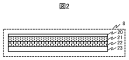
- FIG. 2 is a diagram illustrating an example of a cross-sectional structure of the display 8 including the liquid crystal panel 22 and the touch panel 21.
- the touch panel 21 is arranged on the upper surface of the liquid crystal panel 22 to integrate them
- the protective cover 20 such as glass is arranged on the upper surface of the touch panel 21
- the backlight 23 is arranged on the lower surface of the liquid crystal panel 22.
- the touch panel 21 is of a capacitive type, for example, and transparent electrodes are arranged in a two-dimensional shape orthogonal to each other.
- a human finger or touch pen touches or approaches the display screen of the display 8
- the capacitance between the finger or touch pen and the transparent electrode changes, and the horizontal and vertical positions on the touched screen are detected.
- the display and operation of the display 8 including the touch panel 21 will be described later.
- the detection accuracy is improved by arranging the touch panel 21 so as to be in close contact with the protective cover 20.
- the glossy finish on the surface of the protective cover 20 increases the clarity of the display image on the liquid crystal panel 22 and improves sliding of the finger and the touch pen.
- the surface of the protective cover 20 has a gloss finish, the amount of reflection of light from the outside increases.
- the backlight 23 emits illumination light from the back surface of the liquid crystal panel 22 to display an image.
- the backlight 23 is controlled to be turned off to reduce power consumption.
- the backlight 23 may be turned off for the entire display 8, or the backlight 23 may be divided into a plurality of parts and controlled, and a part of the display 8 may be turned off.
- a panel such as an organic EL may be used instead of the liquid crystal panel 22 and the backlight 23 .
- a display panel using a light emitting element such as an organic EL does not require a backlight.
- the touch panel 21 may use a pressure-sensitive method or the like in addition to the capacitance method.
- FIG. 3 is a diagram illustrating an example of the appearance of the mobile terminal 1
- FIG. 3A is a view of the mobile terminal 1 viewed from the back side
- FIG. 3B is a view of the mobile terminal 1 viewed from the side surface
- FIG. 3C is a diagram of the mobile terminal 1 as viewed from the front side.
- a display 8 in which a touch panel 21 is integrated is disposed on the back surface of the mobile terminal 1.
- the lens portion 2a of the rear camera is disposed on the front surface
- the lens portion 2b of the front camera is disposed on the rear surface.
- each of the lens portions 2a and 2b is a fixed type on the front and back surfaces.
- the lens units 2a and 2b may be detachable and interchangeable with lenses having different focal lengths.
- the power switch 33 is a switch that is operated when the portable terminal 1 is activated and terminated.
- the portable terminal 1 may have a power saving mode, and may also be used as a switch for returning to the power saving mode.
- the speaker 32 and the microphone 34 are for, for example, a telephone call, they are arranged so as to be close to the caller's ear and mouth during a telephone call.
- the proximity sensor 31 is disposed near the speaker 32 in order to detect, for example, the approach of the face during a call, and the infrared proximity sensor includes a near infrared light emitting part and a light receiving part. As will be described later, the proximity sensor 31 is disposed on the same surface as the display 8, that is, the back surface, in order to detect the attachment of the viewer.
- a speaker 32 and a microphone 34 are also arranged on the back side.
- the shutter 35 is a switch for instructing photographing through the lens unit 2a, and may coexist with a shutter by touching a part of the touch panel 21, or the shutter 35 may not be provided.
- the example of FIG. 3B is an example of the arrangement of the power switch 33 and the shutter 35, and is not limited to this arrangement.
- FIG. 4 is a diagram illustrating an example of the viewer 40 attached to the mobile terminal 1.
- the viewer 40 has a structure that can be attached to and detached from the back surface of the mobile terminal 1.
- 4A is a view of the viewer 40 viewed from the back side
- FIG. 4B is a view of the viewer 40 viewed from the side
- FIG. 4C is a view of the viewer 40 viewed from the front side.
- the back surface, the side surface, and the front surface are the same surfaces as the portable terminal 1 shown in FIG. 3, and are not surfaces based on the structure of the viewer 40.
- the viewer 40 includes a finder unit 42a.
- the finder portion 42a has a shape in which four sides are surrounded by a rectangular tube, that is, a substantially rectangular light shielding plate, and blocks light from the side surface.
- the opening 41 of the finder part 42a is an opening that allows light from the front side to the back side of the viewer 40 to pass therethrough. This will be described later with reference to FIG.
- the cavity 43 is a cavity that allows light and a human finger or touch pen to pass between the front side and the back side of the viewer 40.
- the entire viewer 40 has a shape that is attached so as to cover a part of the back surface and side surface of the mobile terminal 1, and is a light shielding material, for example, a material such as colored polycarbonate.
- the viewer 40 and the portable terminal 1 may be shaped so as to maintain the wearing state by being sandwiched between fingers, or the viewer 40 and the portable terminal 1 have irregularities not shown, and the irregularities are fitted.
- the shape which maintains a mounting state by being done may be sufficient.
- the viewer 40 has a shape that is detected by the proximity sensor 31 in a state where the viewer 40 is mounted on the mobile terminal 1. For this reason, at the time of mounting, the opening 41 and the cavity 43 are not positioned to face the proximity sensor 31, and a part of the viewer 40 excluding the opening 41 and the cavity 43 is positioned to face the proximity sensor 31.
- FIG. 5 is a cross-sectional view showing an example of the finder portion 42a.
- the cover glass 50 and the lens 51 are fitted into the opening 41 of the finder portion 42a, and the side surfaces of the finder portion 42a serve as support members.
- the display 8 is directly viewed without the viewer 40, the display 8 is normally viewed from a distance of about 30 cm or more from the display 8, whereas when the viewer 40 is used, the display 8 is viewed while looking through the finder portion 42a. Therefore, the image displayed on the display 8 is enlarged by the lens 51 and adjusted so as to be in focus.
- the cover glass 50 protects the lens 51. It is preferable that the finder part 42a extends from the eyepiece position to the cover glass 50. A shape in which the cover glass 50 is shielded from external light by the side face of the finder part 42a and the human face looked into is preferable.
- FIG. 6A is a diagram showing an example of display when the viewer 40 is not attached
- FIG. 6B is a diagram showing an example of display when the viewer 40 is attached.
- the display on the display 8 is changed depending on whether or not the viewer 40 is attached, that is, whether or not the viewer 40 is used.
- the display 8 is directly viewed.
- a subject 67a is a display of the subject imaged by the imaging unit 3a.
- the imaging area 66a is preferably a display of a range captured by the imaging unit 3a, but may be a display of a part of the range with its surroundings clipped.
- the display of the subject 67a and the imaging region 66a may be reduced and displayed according to the ratio between the number of pixels of the imaging units 3a and 3b and the number of pixels of the display 8.
- the setting buttons 60 to 64 are displays of various setting buttons, and the shutter button 65 is a display of buttons serving as shutters.
- the setting button 60 is for switching between the front camera and the rear camera, the setting button 61 is for changing the ISO sensitivity, and the setting button 62 is for changing the aperture value. 63 is for changing the shutter speed, and the setting button 64 is for setting the flash.
- These setting buttons 60 to 64 are operation menus for setting the camera, and are displayed on the display 8 to detect that the position corresponding to the display on the touch panel 21 of the operation input unit 9 is touched. Then, the setting is changed by the processing of the control circuit 6. For example, each time the setting button 60 is touched, the rear camera and the front camera are switched. Further, when the setting button 61 is touched, selectable ISO sensitivity is displayed by horizontal scrolling, and when selected by touching, the ISO sensitivity is changed. The aperture value of the setting button 62 and the shutter speed of the setting button 63 operate similarly to the setting button 61. Each time the setting button 64 is touched, ON (forced light emission), OFF (light emission inhibition), and automatic light emission (light emission control according to brightness) are set.
- These setting buttons 60 to 64 are examples of operation menus, and an arbitrary setting change menu and setting buttons such as a mode change to a shooting mode including moving image shooting and a playback mode, a focus mode, and a white balance are displayed. May be.
- the shutter button 65 has the same operation as the shutter 35 and may be used in combination.
- the video imaged by the imaging unit 3b as a front camera is displayed on the display 8, it is displayed as a mirror image, and the other images are usually displayed as normal images.
- 6A may be a general display or operation of a smartphone.
- the region 68 is a region corresponding to the hollow portion 43, and the region 68 can be directly viewed and touched through the hollow portion 43 even when the viewer 40 is attached.
- the display of the setting buttons 60 to 64 and the shutter button 65 in FIG. 6B is the same as the display example in FIG. 6A, but may be displayed smaller than the display in FIG.
- the setting button 60 for switching between the rear camera and the front camera may not be displayed using only the rear camera, or the setting button 60 may be grayed out and cannot be selected. . Further, when the attachment of the viewer 40 is detected, the setting buttons 60 to 64 may be changed to different operation menus.
- the subject 67b and the imaging region 66b correspond to the subject 67a and the imaging region 66a, respectively, and are displayed using the same video data as the imaging display by one operation of the shutter 35 and the shutter button 65.
- the subject 67a and the imaging region 66a are displayed at the same magnification
- the subject 67b and the imaging region 66b are displayed in a reduced size.
- the subject 67b and the imaging area 66b are displayed. This reduction is performed by the image / audio signal processing circuit 5.
- the size of the imaging region 66b is preferably a size that allows the image displayed in the imaging region 66b to be sufficiently confirmed from corner to corner by the enlargement of the lens 51.
- the reduction ratio to this size may be set by a touch operation, for example, by displaying a magnification setting button on the operation menu of the setting buttons 60 to 64. Further, the distance from the display 8 to the lens 51, the distance from the lens 51 to the eye to be looked into, the focal distance of the lens 51, etc. are preset, and the screen size and resolution of the display 8 are acquired, and the reduction magnification is obtained. It may be calculated.
- the display around the imaging region 66b that is, the hatched portion of the region 69 may be displayed with reduced brightness or black.
- the liquid crystal panel 22 may be controlled, or the backlight 23 may be controlled.
- the installation of the viewer 40 is detected by the proximity sensor 31.
- the control circuit 6 changes to the display shown in FIG. 6B. You may control. That is, the control circuit 6 may perform control so that the imaging area 66b including the subject 67b is reduced and displayed with the display luminance of the area 69 lowered.
- the removal of the viewer 40 is detected by the proximity sensor 31.
- the control circuit 6 changes to the display shown in FIG. 6A. You may control to do.
- a setting button for switching is also displayed on the operation menu of the setting buttons 60 to 64, and the display shown in FIG. 6A and the display shown in FIG. 6B may be controlled to be switched by a touch operation.
- the display 8 screen When shooting a still image or a moving image and the surroundings are bright, the display 8 screen may be difficult to see. In such a case, when the viewer 40 is attached, the light shielding property is improved, and the video of the subject 67b can be easily confirmed even in a bright place.
- FIG. 7A is a diagram showing an example of display including the focus setting area frame 70a when the viewer 40 is not attached.
- the same display as in FIG. In the display shown in FIG. 6A, for example, when the touch panel 21 detects that an arbitrary position in the display of the imaging region 66a is touched, the control circuit 6 sets the distance of the imaging target corresponding to the touched position. The focus is set and the focus setting area frame 70a is displayed.
- FIG. 7B is a diagram showing an example of display including the focus setting area frame 70b when the viewer 40 is attached.
- the touch pad area 71 is touched via the area 68 corresponding to the cavity 43, and moves the position of the focus setting area frame 70b in the imaging area 66b according to the touched position in the area 68. Then, the control circuit 6 controls.
- the position of the focus setting area frame 70b can be moved. Further, icons and the like corresponding to the setting buttons 60 to 64 shown in FIG. 7A are displayed in the display of the imaging region 66b, and the icons and the like are selected according to the position of the focus setting region frame 70b.
- the control circuit 6 may control.
- FIG. 8 is a diagram illustrating another example of the viewer 40.
- 8A is a view of the viewer 40 viewed from the back side
- FIG. 8B is a view of the viewer 40 viewed from the side
- FIG. 8C is a view of the viewer 40 viewed from the front side.
- the same structure as that of FIG. FIG. 8 differs from FIG. 4 in the shape of the finder part 42b.
- each of the side surfaces of the finder portion 42a is substantially rectangular, but in the example shown in FIG. 8, each of the side surfaces of the finder portion 42b is substantially trapezoidal. That is, the opening 41 becomes wider as it approaches the display 8. As a result, the area where the inner side of the finder portion 42b, that is, the inner surface on the opening 41 side can be seen when viewed, is reduced, and the display area of the imaging area 66b shown in FIGS. 6B and 7B is widened. In some cases, the number of pixels can be increased. Further, by making the side surface of the finder portion 42b substantially trapezoidal, the physical structural strength is also increased.
- the same function as that of the viewfinder can be obtained by simply mounting the viewer 40 on the portable terminal 1 that includes the display 8 such as a liquid crystal panel but does not include the electronic viewfinder.
- the effect is obtained.
- the viewer 40 does not include display parts unlike the electronic viewfinder, and the structure is simple and the cost is low.
- the viewer 40 can be substantially used. Since the display can be automatically switched between when the viewer 40 is attached and when the viewer 40 is not attached, an easy-to-use portable terminal can be provided. Furthermore, even if the viewer 40 is attached, the manual focus setting area frame can be moved.
- FIG. 9 is a block diagram illustrating an example of the configuration of the mobile terminal 1 according to the second embodiment.
- the same structure as that of FIG. 1 has two lens units 2a and 2b and two imaging units 3a and 3b corresponding to the front camera and the rear camera, whereas the example of FIG. 9 further includes a lens unit 2c and an imaging unit 3c. .
- the lens unit 2c and the imaging unit 3c are combined with the lens unit 2a and the imaging unit 3a so that the front camera can cope with stereo imaging and the like.
- the imaging unit 3 a and the imaging unit 3 b are controlled so as to capture images at the same timing, and the interface circuit 4 outputs both input signals from the imaging units 3 a and 3 c to the image / audio signal processing circuit 5.
- the image / audio signal processing circuit 5 generates video data for display of both input signals and outputs the video data to the display 8. This display will be described later.
- FIG. 10 is a diagram illustrating an example of the appearance of the mobile terminal 1 according to the second embodiment.
- 10A is a diagram of the mobile terminal 1 viewed from the back side
- FIG. 10B is a diagram of the mobile terminal 1 viewed from the side
- FIG. 10C is a diagram of the mobile terminal 1 viewed from the front side. It is.
- the lens unit 2a and the lens unit 2c are arranged in the vertical direction on the front surface of the mobile terminal 1 at a predetermined interval.
- the arrangement in the vertical direction is to support shooting with the mobile terminal 1 in the horizontal direction, and is not limited to this, but is preferably arranged in the long side direction of the display 8.
- FIG. 11 is a diagram illustrating an example of the viewer 80 according to the second embodiment.
- the viewer 40 has a structure that can be attached to and detached from the back surface of the mobile terminal 1. Although it is preferable to be attached to the portable terminal 1 shown in FIGS. 9 and 10 of the present embodiment, it is attached to the portable terminal 1 shown in FIGS. May be.
- the viewer 80 attached to the portable terminal 1 shown in FIGS. 9 and 10 of the present embodiment captures images corresponding to the right eye and the left eye at the same time with the two imaging units of the imaging unit 3a and the imaging unit 3c. Sometimes used.
- the viewer 80 is used for viewing 3D images during reproduction.
- 11A is a view of the viewer 80 viewed from the back side
- FIG. 11B is a view of the viewer 80 viewed from the side
- FIG. 11C is a view of the viewer 80 viewed from the front side.
- each of the finder portions 82a and 82c has a shape in which the side surfaces are surrounded by a rectangular tube, that is, a substantially rectangular light shielding plate, and blocks light from the side surfaces.
- the openings 81a and 81c of the finder portions 82a and 82c are openings that allow light from the front side to the back side of the viewer 80 to pass therethrough.
- the cavity 83 is a cavity that allows light and a human finger or touch pen to pass between the front side and the back side of the viewer 80.
- the finder unit 82a and the finder unit 82c are arranged on the back surface of the viewer 80 at predetermined intervals in the vertical direction. This corresponds to the arrangement of the lens units 2a and 2c shown in FIG. 10 (c), and when the mobile terminal 1 is photographed sideways, the finder unit 82a and the finder unit 82c are respectively left eye and right eye. It is an arrangement to look into. In order to increase the area of the openings 81a and 81c, it is preferable to arrange them side by side in the long side direction of the display 8.
- the structure of each of the finder portions 82a and 82c is as described with reference to FIG.
- the hollow portion 83 is shown in FIGS. 11A and 11C as an example in which the touch panel 21 is easily operated with the thumb when the portable terminal 1 is photographed sideways, but is not limited thereto. It is not a thing and it may be arrange
- FIG. 12A is a diagram showing an example of display of the shooting mode when the viewer 80 is attached.
- the display 8 displays imaging areas 91a and 91c, setting buttons 61 to 63, and a shutter button 65.
- the setting buttons 61 to 63 and the shutter button 65 are as described with reference to FIG. 6A.
- the setting buttons 61 to 63 and the shutter button 65 are displayed in an area 90 corresponding to the cavity 83.
- Each of the imaging area 91a and the imaging area 91c is a display of a range captured by the imaging unit 3a and the imaging unit 3c.
- the display of the imaging area 91a can be seen through the opening 81a and the imaging can be performed through the opening 81c.
- the area 91c is displayed at a position where it can be seen.
- the subject 94a and the subject 94c are the same as objects, they are captured by the image capturing unit 3a and the image capturing unit 3c, and thus are captured from different angles.
- the video data obtained by imaging by the imaging unit 3a is displayed in the imaging area 91a as the subject 94a, and the display of the subject 94a is viewed by the left eye through the finder unit 82a, and is captured by the imaging unit 3c.
- the video data obtained in this way is displayed as a subject 94c in the imaging area 91c, and the display of the subject 94c can be viewed with the right eye through the viewfinder unit 82c, so that it can be viewed as a 3D image.
- the display includes the imaging region 66a shown in FIG. 6A instead of the two displays of the imaging region 91a and the imaging region 91c. May be.
- video data obtained by imaging in either the imaging unit 3a or the imaging unit 3c may be displayed.
- the display of the imaging area 91a and the imaging area 91c may be smaller than the display of the imaging area 66a, and the display of the subject 94a and the subject 94c may be reduced smaller than the display of the subject 67a.
- the display size of the imaging area 91a and the imaging area 91c may be the same.
- the display of the viewer 80 may be detected by the proximity sensor 31 and the display screen may be switched.
- FIG. 12B is a diagram showing a display example of the playback mode when the viewer 80 is attached.
- the setting buttons 61 to 63 may be operation menus for reproduction. Alternatively, it may be a display of setting contents at the time of shooting the image to be reproduced.
- a recorded image selection button 95 displayed instead of the shutter button 65 is a display for input used to select an image to be reproduced.
- the display areas 93a and 93c are displays of images to be reproduced.
- subjects 94d and 94e are displayed in the same manner as the subjects 94a and 94c shown in FIG. 12A.
- the display areas 93a and 93c are displayed at the same positions as the imaging areas 91a and 91c. Accordingly, it can be viewed as a 3D image in the same manner as described with reference to FIG. 12A.
- the imaging regions 92a and 92c are displays of images captured by the imaging units 3a and 3c. Even in the reproduction mode, the imaging units 3a and 3c capture images, and the captured images are combined and displayed on a part of the display areas 93a and 93c in real time. When the viewer 80 is used during reproduction, the viewfinders 82a and 82c are shielded from light and the surroundings cannot be seen. It becomes possible to confirm the situation. This synthesis and superimposition may be performed by the image / audio signal processing circuit 5.
- the display of the imaging regions 92a and 92c in the playback mode may be switched on and off by a setting button or the like not shown.
- a reproduced image may be displayed in a superimposed manner on part of the imaging areas 91a and 91c.
- the viewer 80 Since the positional relationship between the lens units 2a and 2c, the portable terminal 1, and the viewer 80 attached to the portable terminal 1 is fixed, the viewer 80 looks in the direction in which the lens units 2a and 2c are directed in the shooting mode. It becomes. Even in the reproduction mode, as in this state, the display images of the display areas 93a and 93c may be changed according to the direction in which the lens units 2a and 2c are directed.
- the direction in which the lens units 2 a and 2 c are directed is also the direction of the viewer 80 and the portable terminal 1.
- the posture of the portable terminal 1 is detected by the posture detection unit 7, and the viewer 80 mounted on the portable terminal 1.
- the direction of peeking is specified.
- video data recorded in the shooting direction which is cut out in accordance with the direction in which the viewer 80 is directed, is extracted from the video data obtained by imaging at an ultra-wide angle. It may be displayed in the display areas 93a and 93c.
- Video data obtained by imaging at an ultra-wide angle may be obtained by imaging with the portable terminal 1 using the lenses 2a and 2c as ultra-wide-angle lenses, or images captured by other devices are captured. Also good. Further, for example, it is possible to view the image in the direction corresponding to the direction to which the viewer 80 is directed in 3D while reproducing the video data of a so-called all-sky image having an angle of view of 360 degrees and observing the image using the viewer 80. You can enjoy realistic images.
- the surroundings can be confirmed and the safety can be improved by displaying the images captured by the imaging units 3a and 3c superimposed on the reproduced image. .
- photographs with one of the imaging part 3a or the imaging part 3c of the portable terminal 1 shown to FIG. 9, 10 of a present Example and performs the display shown to FIG. 6A, 6B, 7A, 7B of Example 1.
- FIG. 4 and the viewer 80 shown in FIG. 11 may be selectively used according to one or both of the imaging unit 3a and the imaging unit 3b.
- the viewer 80 can view the shooting target as a 3D image when shooting the 3D image, and can also view the 3D image when reproducing the 3D image.
- the mobile terminal 1 includes a general-purpose device such as a tablet terminal or a smartphone having an imaging unit.
- a general-purpose device such as a tablet terminal or a smartphone having an imaging unit.
- the present invention mainly focuses on imaging such as a digital camera or a video camera. It can also be applied to an imaging device including a dedicated machine.
- the present invention it is possible to use a part of the display in the same manner as the electronic viewfinder by mounting the viewer on the portable terminal provided with the imaging unit. This makes it easy to monitor images even in bright outdoors.
- the display screen can be automatically switched between using the viewer and not using it. This makes it possible to provide a portable terminal and an imaging device that are easy to use.
Abstract
L'invention concerne un terminal mobile, comprenant une unité de capture d'image située sur un côté de surface avant et une unité d'affichage et un capteur situés sur un côté de surface arrière, comprend une unité de traitement de signal qui, à partir d'un signal émis par l'unité de capture d'image, génère des informations devant être affichées par l'unité d'affichage et une unité de commande dans laquelle un signal en provenance du capteur est entré et qui commande l'unité de traitement de signal. Un état d'affichage de l'unité d'affichage en fonction de la commande effectuée par l'unité de commande comprend un premier état d'affichage pour un affichage dans une première zone d'affichage si aucun signal de détection n'est en cours d'entrée à partir du capteur, et un second état d'affichage pour un affichage dans une seconde zone d'affichage si un signal de détection est en cours d'entrée à partir du capteur.
Priority Applications (6)
| Application Number | Priority Date | Filing Date | Title |
|---|---|---|---|
| CN201780038953.9A CN109417599B (zh) | 2016-06-23 | 2017-06-01 | 便携终端 |
| US16/311,132 US10911661B2 (en) | 2016-06-23 | 2017-06-01 | Mobile terminal |
| US17/135,958 US11323611B2 (en) | 2016-06-23 | 2020-12-28 | Mobile terminal |
| US17/714,696 US11490004B2 (en) | 2016-06-23 | 2022-04-06 | Mobile terminal |
| US17/943,966 US11750915B2 (en) | 2016-06-23 | 2022-09-13 | Mobile terminal |
| US18/357,568 US20240022808A1 (en) | 2016-06-23 | 2023-07-24 | Mobile terminal |
Applications Claiming Priority (2)
| Application Number | Priority Date | Filing Date | Title |
|---|---|---|---|
| JP2016-124538 | 2016-06-23 | ||
| JP2016124538A JP6829015B2 (ja) | 2016-06-23 | 2016-06-23 | 携帯端末 |
Related Child Applications (2)
| Application Number | Title | Priority Date | Filing Date |
|---|---|---|---|
| US16/311,132 A-371-Of-International US10911661B2 (en) | 2016-06-23 | 2017-06-01 | Mobile terminal |
| US17/135,958 Continuation US11323611B2 (en) | 2016-06-23 | 2020-12-28 | Mobile terminal |
Publications (1)
| Publication Number | Publication Date |
|---|---|
| WO2017221664A1 true WO2017221664A1 (fr) | 2017-12-28 |
Family
ID=60784212
Family Applications (1)
| Application Number | Title | Priority Date | Filing Date |
|---|---|---|---|
| PCT/JP2017/020460 WO2017221664A1 (fr) | 2016-06-23 | 2017-06-01 | Terminal mobile |
Country Status (4)
| Country | Link |
|---|---|
| US (5) | US10911661B2 (fr) |
| JP (1) | JP6829015B2 (fr) |
| CN (1) | CN109417599B (fr) |
| WO (1) | WO2017221664A1 (fr) |
Families Citing this family (3)
| Publication number | Priority date | Publication date | Assignee | Title |
|---|---|---|---|---|
| US11157738B2 (en) * | 2018-11-30 | 2021-10-26 | Cloudminds Robotics Co., Ltd. | Audio-visual perception system and apparatus and robot system |
| US11917119B2 (en) | 2020-01-09 | 2024-02-27 | Jerry Nims | 2D image capture system and display of 3D digital image |
| WO2022261111A1 (fr) * | 2021-06-07 | 2022-12-15 | Jerry Nims | Système de capture d'images numériques 3d et simulation de séquence d'images numériques 3d |
Citations (4)
| Publication number | Priority date | Publication date | Assignee | Title |
|---|---|---|---|---|
| JPH09215012A (ja) * | 1996-02-08 | 1997-08-15 | Sony Corp | 立体映像撮影装置及び該装置を用いる立体映像撮影記録再生装置 |
| JP2001320610A (ja) * | 2000-05-02 | 2001-11-16 | Nikon Corp | 電子スチルカメラ |
| JP2010212876A (ja) * | 2009-03-09 | 2010-09-24 | Canon Inc | 撮像装置 |
| JP2012089973A (ja) * | 2010-10-18 | 2012-05-10 | Olympus Imaging Corp | カメラ |
Family Cites Families (17)
| Publication number | Priority date | Publication date | Assignee | Title |
|---|---|---|---|---|
| JP2001136499A (ja) | 1999-11-04 | 2001-05-18 | Toshiba Corp | 映像通信端末 |
| JP2002010112A (ja) | 2000-06-20 | 2002-01-11 | Sony Corp | 電子ビューファインダ |
| JP2004135177A (ja) * | 2002-10-11 | 2004-04-30 | Sharp Corp | 携帯電話機 |
| JP3829144B2 (ja) | 2004-11-25 | 2006-10-04 | シャープ株式会社 | 合焦エリア調節カメラ付携帯端末 |
| JP5163257B2 (ja) * | 2008-04-23 | 2013-03-13 | ソニー株式会社 | 撮像装置 |
| CN101359152A (zh) * | 2008-09-27 | 2009-02-04 | 尹兴道 | 便携分体式数码相机 |
| KR101735610B1 (ko) * | 2010-05-06 | 2017-05-15 | 엘지전자 주식회사 | 영상표시장치의 동작 방법 |
| JP5686244B2 (ja) * | 2010-12-21 | 2015-03-18 | ソニー株式会社 | 表示制御装置、表示制御方法、及び、プログラム |
| KR101545883B1 (ko) * | 2012-10-30 | 2015-08-20 | 삼성전자주식회사 | 단말의 카메라 제어 방법 및 그 단말 |
| KR102056128B1 (ko) * | 2013-02-28 | 2019-12-17 | 삼성전자 주식회사 | 위젯을 이용한 사진 촬영 방법 및 휴대 장치 |
| JP2015007949A (ja) * | 2013-06-26 | 2015-01-15 | ソニー株式会社 | 表示装置、表示制御方法及びコンピュータプログラム |
| CN107005675B (zh) * | 2014-09-05 | 2019-08-06 | 富士胶片株式会社 | 动态图像编辑装置、动态图像编辑方法及存储介质 |
| KR102250093B1 (ko) * | 2014-12-18 | 2021-05-10 | 삼성전자주식회사 | 디스플레이 장치 및 디스플레이 장치의 콘텐트 출력 제어방법 |
| US10455143B2 (en) * | 2015-03-18 | 2019-10-22 | Gentex Corporation | Vehicle display with view control |
| KR102339178B1 (ko) * | 2015-08-27 | 2021-12-14 | 엘지전자 주식회사 | 이동단말기 및 그 제어방법 |
| US10044927B2 (en) * | 2015-10-19 | 2018-08-07 | Stmicroelectronics International N.V. | Capturing a stable image using an ambient light sensor-based trigger |
| US11481915B2 (en) * | 2018-05-04 | 2022-10-25 | Packsize Llc | Systems and methods for three-dimensional data acquisition and processing under timing constraints |
-
2016
- 2016-06-23 JP JP2016124538A patent/JP6829015B2/ja active Active
-
2017
- 2017-06-01 CN CN201780038953.9A patent/CN109417599B/zh active Active
- 2017-06-01 US US16/311,132 patent/US10911661B2/en active Active
- 2017-06-01 WO PCT/JP2017/020460 patent/WO2017221664A1/fr active Application Filing
-
2020
- 2020-12-28 US US17/135,958 patent/US11323611B2/en active Active
-
2022
- 2022-04-06 US US17/714,696 patent/US11490004B2/en active Active
- 2022-09-13 US US17/943,966 patent/US11750915B2/en active Active
-
2023
- 2023-07-24 US US18/357,568 patent/US20240022808A1/en active Pending
Patent Citations (4)
| Publication number | Priority date | Publication date | Assignee | Title |
|---|---|---|---|---|
| JPH09215012A (ja) * | 1996-02-08 | 1997-08-15 | Sony Corp | 立体映像撮影装置及び該装置を用いる立体映像撮影記録再生装置 |
| JP2001320610A (ja) * | 2000-05-02 | 2001-11-16 | Nikon Corp | 電子スチルカメラ |
| JP2010212876A (ja) * | 2009-03-09 | 2010-09-24 | Canon Inc | 撮像装置 |
| JP2012089973A (ja) * | 2010-10-18 | 2012-05-10 | Olympus Imaging Corp | カメラ |
Also Published As
| Publication number | Publication date |
|---|---|
| JP2017228969A (ja) | 2017-12-28 |
| US20220232158A1 (en) | 2022-07-21 |
| CN109417599A (zh) | 2019-03-01 |
| US20190215446A1 (en) | 2019-07-11 |
| US20210120172A1 (en) | 2021-04-22 |
| CN109417599B (zh) | 2021-02-12 |
| JP6829015B2 (ja) | 2021-02-10 |
| US20240022808A1 (en) | 2024-01-18 |
| US10911661B2 (en) | 2021-02-02 |
| US11750915B2 (en) | 2023-09-05 |
| US11490004B2 (en) | 2022-11-01 |
| US20230007165A1 (en) | 2023-01-05 |
| US11323611B2 (en) | 2022-05-03 |
Similar Documents
| Publication | Publication Date | Title |
|---|---|---|
| JP6878548B2 (ja) | 撮像装置 | |
| JP4510713B2 (ja) | デジタルカメラ | |
| US8976270B2 (en) | Imaging device and imaging device control method capable of taking pictures rapidly with an intuitive operation | |
| JP5946970B2 (ja) | 撮像装置及び撮像方法 | |
| CN114143464A (zh) | 摄像装置及其设定画面 | |
| US11490004B2 (en) | Mobile terminal | |
| JP5719223B2 (ja) | 画像記録装置、記録方法およびプログラム | |
| JP2013090056A (ja) | 画像再生装置及びカメラ | |
| JP2016103666A (ja) | 電子機器および撮像装置 | |
| JP5226546B2 (ja) | 撮像装置 | |
| JP2012134680A (ja) | 撮像装置 | |
| JP5907602B2 (ja) | 撮像装置及び撮像装置の制御方法 | |
| JP2011112717A (ja) | カメラ | |
| JP2008249928A (ja) | 撮像装置 | |
| JP2015159550A (ja) | 撮像装置、撮像方法およびプログラム | |
| JP6169230B2 (ja) | カメラ装置 | |
| JP6042918B2 (ja) | カメラ | |
| JP5963890B2 (ja) | 撮像装置、撮像装置の制御方法および撮像装置のモード切換えプログラム | |
| JP2017085205A (ja) | 撮像装置 |
Legal Events
| Date | Code | Title | Description |
|---|---|---|---|
| 121 | Ep: the epo has been informed by wipo that ep was designated in this application |
Ref document number: 17815133 Country of ref document: EP Kind code of ref document: A1 |
|
| NENP | Non-entry into the national phase |
Ref country code: DE |
|
| 122 | Ep: pct application non-entry in european phase |
Ref document number: 17815133 Country of ref document: EP Kind code of ref document: A1 |