WO2017221598A1 - 包装体 - Google Patents
包装体 Download PDFInfo
- Publication number
- WO2017221598A1 WO2017221598A1 PCT/JP2017/018801 JP2017018801W WO2017221598A1 WO 2017221598 A1 WO2017221598 A1 WO 2017221598A1 JP 2017018801 W JP2017018801 W JP 2017018801W WO 2017221598 A1 WO2017221598 A1 WO 2017221598A1
- Authority
- WO
- WIPO (PCT)
- Prior art keywords
- plate
- box
- opening
- package
- buffer
- Prior art date
- Legal status (The legal status is an assumption and is not a legal conclusion. Google has not performed a legal analysis and makes no representation as to the accuracy of the status listed.)
- Ceased
Links
Images








Classifications
-
- B—PERFORMING OPERATIONS; TRANSPORTING
- B65—CONVEYING; PACKING; STORING; HANDLING THIN OR FILAMENTARY MATERIAL
- B65D—CONTAINERS FOR STORAGE OR TRANSPORT OF ARTICLES OR MATERIALS, e.g. BAGS, BARRELS, BOTTLES, BOXES, CANS, CARTONS, CRATES, DRUMS, JARS, TANKS, HOPPERS, FORWARDING CONTAINERS; ACCESSORIES, CLOSURES, OR FITTINGS THEREFOR; PACKAGING ELEMENTS; PACKAGES
- B65D77/00—Packages formed by enclosing articles or materials in preformed containers, e.g. boxes, cartons, sacks or bags
- B65D77/22—Details
- B65D77/24—Inserts or accessories added or incorporated during filling of containers
- B65D77/26—Elements or devices for locating or protecting articles
-
- B—PERFORMING OPERATIONS; TRANSPORTING
- B65—CONVEYING; PACKING; STORING; HANDLING THIN OR FILAMENTARY MATERIAL
- B65D—CONTAINERS FOR STORAGE OR TRANSPORT OF ARTICLES OR MATERIALS, e.g. BAGS, BARRELS, BOTTLES, BOXES, CANS, CARTONS, CRATES, DRUMS, JARS, TANKS, HOPPERS, FORWARDING CONTAINERS; ACCESSORIES, CLOSURES, OR FITTINGS THEREFOR; PACKAGING ELEMENTS; PACKAGES
- B65D81/00—Containers, packaging elements, or packages, for contents presenting particular transport or storage problems, or adapted to be used for non-packaging purposes after removal of contents
- B65D81/02—Containers, packaging elements, or packages, for contents presenting particular transport or storage problems, or adapted to be used for non-packaging purposes after removal of contents specially adapted to protect contents from mechanical damage
- B65D81/05—Containers, packaging elements, or packages, for contents presenting particular transport or storage problems, or adapted to be used for non-packaging purposes after removal of contents specially adapted to protect contents from mechanical damage maintaining contents at spaced relation from package walls, or from other contents
- B65D81/107—Containers, packaging elements, or packages, for contents presenting particular transport or storage problems, or adapted to be used for non-packaging purposes after removal of contents specially adapted to protect contents from mechanical damage maintaining contents at spaced relation from package walls, or from other contents using blocks of shock-absorbing material
- B65D81/113—Containers, packaging elements, or packages, for contents presenting particular transport or storage problems, or adapted to be used for non-packaging purposes after removal of contents specially adapted to protect contents from mechanical damage maintaining contents at spaced relation from package walls, or from other contents using blocks of shock-absorbing material of a shape specially adapted to accommodate contents
-
- B—PERFORMING OPERATIONS; TRANSPORTING
- B65—CONVEYING; PACKING; STORING; HANDLING THIN OR FILAMENTARY MATERIAL
- B65D—CONTAINERS FOR STORAGE OR TRANSPORT OF ARTICLES OR MATERIALS, e.g. BAGS, BARRELS, BOTTLES, BOXES, CANS, CARTONS, CRATES, DRUMS, JARS, TANKS, HOPPERS, FORWARDING CONTAINERS; ACCESSORIES, CLOSURES, OR FITTINGS THEREFOR; PACKAGING ELEMENTS; PACKAGES
- B65D51/00—Closures not otherwise provided for
- B65D51/24—Closures not otherwise provided for combined or co-operating with auxiliary devices for non-closing purposes
- B65D51/26—Closures not otherwise provided for combined or co-operating with auxiliary devices for non-closing purposes with means for keeping contents in position, e.g. resilient means
Definitions
- the present invention relates to a package, for example, a package for packing an electronic device having a movable part such as a robot.
- the present invention claims the priority of Japanese Patent Application No. 2016-124398 filed on June 23, 2016, and for the designated countries where weaving by reference is allowed, the contents described in the application are as follows: Is incorporated into this application by reference.
- Patent Document 1 describes a robot packaging container.
- This robot packaging container is a cardboard box, and can accommodate a robot with a plurality of cardboard members attached from above. Moreover, this robot packing container can open a front surface by cutting out a part of front surface, and can draw out a robot from there.
- the present application includes a plurality of means for solving at least a part of the above-described problems, and examples thereof are as follows.
- At least one of the rear buffer members may include a sandwiching portion that sandwiches the movable portion so as to suppress the forward movement of the movable portion.
- the electronic device is a robot including a head portion, a trunk portion, an arm portion, and a leg portion, and at least one of the rear side buffer members moves forward of the head portion. It may have a clamping part which clamps the head so as to suppress the above.
- the packaging body wherein the plurality of rear buffer members extend in a vertical direction and receive a central portion of a rear surface of the electronic device, and extend in a horizontal direction across the vertical buffer member.
- a plurality of lateral cushioning members extending in the lateral direction and receiving the front surface of the electronic device, wherein the plurality of lateral cushioning members on the rear side and the plurality of lateral cushioning members on the front side are spaced apart from each other at a plurality of height positions.
- the electronic device is sandwiched from the front and back facing each other at each height position, and at least one set of the rear lateral cushioning member and the front lateral cushioning member is opposed to each other and engaged with each other. Engagement between the front and back It may have an elephant.
- the outer lid body includes a first plate that covers the opening, and a pair of second plates fixed to the upper and lower ends of the first plate in a state of being bent toward the box body side.
- the distance between the second plates may be larger than the vertical dimension of the opening.
- the packaging body includes a detachable inclined plate at a lower portion of the opening, and the inner lid body includes an upper plate and a lower plate connected with a step at a lower end of the upper plate. And storing the inclined plate enclosed by the outer lid, the step and the lower plate in a state where the inner lid is accommodated in the box and the opening is covered with the outer lid. You may have an intermediate space.
- the present invention it is possible to provide a package that can improve the workability of packaging and unpacking of electronic devices such as robots and can be used repeatedly.
- This embodiment is a package for a robot.
- FIG. 7 is a diagram for explaining the relationship between the buffer members.
- FIG. 7 shows a plan view of each lateral cushioning member in order from the top in the descending order.
- FIG. 7 has shown the side view of each vertical buffer member.
- FIG. 7 shows a side view of the support member 214.
- FIG. 7 is a side view of the left side buffer member 218 and the buffer member 219.
- each buffer member (including the support member 214) is combined by a fitting structure so as to be substantially orthogonal to the other buffer members at a portion (dashed line) indicated by a corresponding lower case alphabet (am).
- the front surface of the vertical buffer member 210 (left in FIG. 7) is formed so as to follow the shape of the central portion so as to come into contact with the lateral central portion of the rear surface of the robot R. Further, the vertical cushioning member 210 has a sandwiching portion 2101 at the top.
- the clamping unit 2101 extends from the rear surface of the head R1 of the robot R through the top of the head to the upper part of the front surface of the head R1 (for example, the forehead).
- the front end portion of the sandwiching portion 2101 protrudes downward and comes into contact with the upper front portion of the head portion R1.
- the clamping unit 2101 can clamp the head R1 from the front-rear direction so as to prevent the head R1 of the robot R from tilting forward.
- the lateral shock-absorbing member 211 and the lateral shock-absorbing member 311 are arranged at the height of the head R1 of the robot R and are sandwiched so as to suppress the front-rear and left-right movements of the head R1.
- the central portion of the lateral shock-absorbing member 211 is formed along the side surface and the rear surface of the head R1 so as to contact the side surface and the rear surface of the head R1.
- the lateral shock-absorbing member 211 is formed with a clamping portion 2111 that sandwiches the head R1 from the left-right direction.
- the lateral shock-absorbing member 211 has a pair of left and right convex portions 2112 for engaging with the pair of left and right concave portions 3112 of the lateral shock-absorbing member 311.
- the central portion of the lateral shock-absorbing member 312 is formed along the side surface and front surface of the upper portion of the trunk portion R2 so as to contact the side surface and front surface of the upper portion of the trunk portion R2 (including the operation panel R5). Further, the lateral cushioning member 312 has a pair of left and right recesses 3121 that receive the pair of left and right sandwiching portions 2121 of the lateral cushioning member 212. The sandwiching portion 2121 and the recessed portion 3121 may be engaged with each other.
- the support member 214 is disposed between the lateral cushioning member 212 and the lateral cushioning member 215, and is fixed to the lateral cushioning member 212 and the lateral cushioning member 215 at the upper and lower ends thereof.
- a lateral cushioning member 213 is fixed to the central portion of the front surface of the support member 214.
- the lateral shock-absorbing member 216 and the lateral shock-absorbing member 316 are disposed at the height of the middle step portion of the leg R3 of the robot R, and are sandwiched so as to suppress the front-rear and left-right movements of the middle step portion of the leg R3.
- the central part of the lateral cushioning member 216 is formed along the side surface and the rear surface of the middle part of the leg R3 so as to contact the side surface and the rear surface of the middle part of the leg R3.
- the central part of the lateral shock-absorbing member 316 is formed along the side surface and the front surface of the middle part of the leg part R3 so as to contact the side surface and the front surface of the middle part of the leg part R3.
- the lateral shock-absorbing member 217 is disposed at the height of the lower part (for example, the foot) of the leg R3 of the robot R, and is sandwiched so as to suppress the front-rear and left-right movements of the lower part of the leg R3.
- the central portion of the lateral shock-absorbing member 217 is formed along the side surface and the rear surface of the lower portion of the leg portion R3 so as to contact the side surface and the rear surface of the lower portion of the leg portion R3.
- the lateral cushioning member 217 is formed with a sandwiching portion 2171 that sandwiches the lower portion of the leg portion R3 from the left and right directions.
- the left side cushioning member 218 and the right side cushioning member 218 are arranged at a height below the leg R3 of the robot R, and sandwich the lower part of the leg R3 from the left and right directions.
- the left side cushioning member 218 is mounted in front of the lower part of the inner surface of the left side wall of the box 2 and is engaged with the left side of the lateral cushioning member 217.
- the right side cushioning member 218 is mounted in front of the lower part of the inner surface of the right side wall of the box 2.
- the outer plate 201 includes a back plate 2011, a pair of left and right side plates 2012, two pairs of upper and lower plates 2013, a pair of upper and lower plates 2014, and a pair of upper and lower plates 2015.
- the two side plates 2012 are connected to the left and right of the back plate 2011, and constitute the left and right walls of the wall portion 20 by being bent substantially vertically at L1.
- the left two plates 2013 are connected to the upper and lower sides of the left side plate 2012, and constitute the upper and lower walls on the left side of the wall portion 20 by being bent substantially vertically at L2.
- the two right plates 2013 are connected to the upper and lower sides of the right side plate 2012, and are bent substantially vertically at L2 to constitute the upper and lower walls on the right side of the wall portion 20.
- each plate of the outer plate portion 201 corresponding to each plate of the inner plate portion 202 can be bonded by, for example, ultrasonic welding, thermal welding, an adhesive, or the like.
- the back plate 2021 and the reinforcing plate 2023 can be bonded together by, for example, ultrasonic welding, heat welding, adhesive, or the like.
- a metal or resin frame may be fitted into the edge of the opening on the front side (the two plates overlap).
- the tip 51 of the inclined plate 5 is formed at an acute angle so that the area in contact with the floor is increased.
- a hook-and-loop fastener 55 is provided on the side of the lower surface of the inclined plate 5 opposite to the tip 51.
- the inclined plate 5 can be fixed to the inner lid 3 by engaging the surface fastener 55 with the surface fastener 35 provided on the front surface of the lower plate 302.
- the inclined plate 5 can be fixed to the box 2 by engaging the hook-and-loop fastener 55 with the hook-and-loop fastener provided near the lower side of the opening of the box 2 (see FIG. 1 and the like).
- FIG. 11 is a development view of the outer lid body 4.
- FIG. 11 also shows a right side view of the outer lid body 4.
- plastic cardboard can be used for the outer lid 4.
- the two plates 41 are processed so as to be swingable about L5.
- the two plates 42 are bent by, for example, ultrasonic waves or heat so as to be fixed in a bent state. Since the outer cover 4 can be hooked on the opening of the box 2 by the upper plate 42 fixed substantially vertically, the operator efficiently performs the work of fixing the left and right plates 41 to the box 2. be able to.
- FIG. 12 is a six-sided view of the buffer member 9 for the operation panel R5.
- FIG. 12 shows the front (a), left side (b), right side (c), plane (d), back (e), and bottom (f) of the buffer member 9.
- FIG. 12 also shows a perspective view of the buffer member 9.
Landscapes
- Engineering & Computer Science (AREA)
- Mechanical Engineering (AREA)
- Buffer Packaging (AREA)
- Packages (AREA)
- Closures For Containers (AREA)
- Packaging Of Machine Parts And Wound Products (AREA)
Abstract
ロボット等の電子機器の梱包及び開梱の作業性を向上でき、かつ、繰り返し利用できる包装体を提供する。 包装体は、前面に開口が設けられた箱体と、前記箱体内に収納される電子機器を前記箱体の前面側から覆う、前記箱体に着脱自在な内蓋体と、前記箱体の外側から前記開口を覆う、前記箱体に着脱自在な外蓋体と、を備える。前記箱体は、前記電子機器の後面側を受ける複数の後側緩衝部材を有する。前記内蓋体は、前記電子機器の前面側を受ける複数の前側緩衝部材を有する。
Description
本発明は、包装体に関し、例えばロボット等の可動部を有する電子機器を梱包するための包装体に関する。本発明は2016年6月23日に出願された日本国特許の出願番号2016-124398の優先権を主張し、文献の参照による織り込みが認められる指定国については、その出願に記載された内容は参照により本出願に織り込まれる。
特許文献1には、ロボット梱包容器について記載されている。このロボット梱包容器は、段ボール製の箱であり、複数の段ボール製の部材を取り付けたロボットを、上面から収容することができる。また、このロボット梱包容器は、前面の一部を切り取ることにより前面を開くことでき、そこからロボットを外に引き出すことができる。
例えばロボットのレンタルを考えた場合、ロボットの梱包作業及び開梱作業は、貸出及び返却の度に繰り返し行われる。従って、これらの作業の効率は重要である。特許文献1のロボット梱包容器にロボットを梱包する際には、作業者は、ロボットを持ち上げて箱の上側から箱に入れる必要がある。そのため、重いロボットを収容するには作業性が低い。また、特許文献1のロボット梱包容器を開梱すると、その容器の前面が破壊される。そのため、当該ロボット梱包容器は、ロボットの再梱包に利用することができない。
本発明の目的は、ロボット等の電子機器の梱包及び開梱の作業性を向上でき、かつ、繰り返し利用できる包装体を提供することにある。
本願は、上記課題の少なくとも一部を解決する手段を複数含んでいるが、その例を挙げるならば、以下のとおりである。
本発明の一態様は、可動部を有する電子機器用の包装体であって、前面に開口が設けられた箱体と、前記箱体内に収納される前記電子機器を前記箱体の前面側から覆う、前記箱体に着脱自在な内蓋体と、前記箱体の外側から前記開口を覆う、前記箱体に着脱自在な外蓋体と、を備え、前記箱体は、前記電子機器の後面側を受ける複数の後側緩衝部材を有し、前記内蓋体は、前記電子機器の前面側を受ける複数の前側緩衝部材を有する。
上記の包装体であって、前記後側緩衝部材の少なくとも1つは、前記可動部の前方への動きを抑制するように前記可動部を挟持する挟持部を有してもよい。
上記の包装体であって、前記電子機器は、頭部、胴部、腕部、及び脚部を含むロボットであり、前記後側緩衝部材の少なくとも1つは、前記頭部の前方への動きを抑制するように前記頭部を挟持する挟持部を有してもよい。
上記の包装体であって、前記後側緩衝部材のうち少なくとも1つは、前記腕部の前方への動きを抑制するように前記腕部を挟持する挟持部を有してもよい。
上記の包装体であって、前記後側緩衝部材は、前記箱体の内部底面に設けられ、前記脚部を上方向に持ち上げるように前記脚部を支持する緩衝部材を含んでもよい。
上記の包装体であって、前記後側緩衝部材及び前記前側緩衝部材の少なくとも1組は、互いに向かい合って係合することにより前記可動部を前後から挟む係合構造を有してもよい。
上記の包装体であって、前記複数の後側緩衝部材は、縦方向に延びて前記電子機器の後面中央部を受ける縦緩衝部材と、前記縦緩衝部材と交差して横方向に延びて前記電子機器の後面を受ける複数の横緩衝部材とを含み、前記複数の前側緩衝部材は、縦方向に延びて前記電子機器の前面中央部を受ける縦緩衝部材と、前記縦緩衝部材と交差して横方向に延びて前記電子機器の前面を受ける複数の横緩衝部材とを含み、前記後側の複数の横緩衝部材及び前記前側の複数の横緩衝部材は、間隔を空けて複数の高さ位置に配置され、各高さ位置において互いに向かい合って前記電子機器を前後から挟み、前記後側の横緩衝部材及び前記前側の横緩衝部材の少なくとも1組は、互いに向かい合って係合することにより前記可動部を前後から挟む係合構造を有してもよい。
上記の包装体であって、前記外蓋体は、前記開口を覆う第1の板と、前記第1の板の上下端に前記箱体側に折り曲げた状態で固定された1組の第2の板を有し、前記第2の板間の距離は、前記開口の上下寸法よりも大きくてもよい。
上記の包装体であって、前記箱体は、後面に、前記開口よりも小さい第2の開口と、前記第2の開口を開閉自在な扉とを有してもよい。
上記の包装体であって、前記箱体は、前記電子機器に付属する器具を収納するケースを格納する内部スペースを有し、後面に前記内部スペースにアクセスするための前記開口よりも小さい第3の開口を有してもよい。
上記の包装体であって、前記開口の下部に着脱可能な傾斜板を備え、前記内蓋体は、上側板と、前記上側板の下端に段差を付けて連結された下側板とを有し、前記内蓋体を前記箱体に収納しかつ前記外蓋体で前記開口を覆った状態で、前記外蓋体と前記段差と前記下側板とにより囲まれる、前記傾斜板を収納するための中間スペースを有してもよい。
上記の包装体であって、前記箱体は、背面および左右側面の壁に対応する板を含む外板部と、背面および左右側面の壁に対応する板を含む内板部とを有し、前記箱体の背面および左右側面の壁は、前記外板部と前記内板部とを重ねて貼り合わせることで形成されてもよい。
本発明によれば、ロボット等の電子機器の梱包及び開梱の作業性を向上でき、かつ、繰り返し利用できる包装体を提供することができる。
上記した以外の課題、構成及び効果は、以下の実施形態の説明により明らかにされる。
以下、本発明の一実施形態について、図面を参照して説明する。本実施形態は、ロボット用の包装体である。
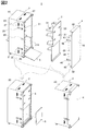
図1は、本発明の一実施形態に係る包装体1の前側斜視図である。図1の上図は、開梱した状態の包装体1を示し、下図は、包装体1の底面を示す。図2は、包装体1の前側斜視図である。図2の上図は、開梱した状態の包装体1を示し、左下図は、箱体2に内蓋体3で蓋をした状態を示し、右下図は、箱体2に外蓋体4で蓋をした状態を示す。図3は、包装体1の後側斜視図である。図3の上図は、箱体2の後側斜視図であり、下図は、ケースCの収納を示す。図4は、包装体1へのロボットRの開梱及び梱包を説明する図である。図4の上図は、ロボットRの正面及び側面と、開梱した状態の包装体1の側面を示す。図4の下図は、ロボットRが梱包された状態の箱体2の正面と、梱包した状態の包装体1の側面を示す。
包装体1は、箱体2と、内蓋体3と、外蓋体4とを備える。箱体2は、ロボットR(図4参照)を出し入れするための開口が正面に設けられた略直方体の壁部20を有する。箱体2は、ロボットRの後側を受けて保持する後側緩衝部21を内部に有する。
内蓋体3は、箱体2の正面の開口から箱体2内に挿入され、箱体2に収容されたロボットRを前側から覆うための部材である。内蓋体3は、板部30と、前側緩衝部31とを有する。板部30は、上下に長い略長方形に構成されている。前側緩衝部31は、板部30の後面に設けられており、ロボットRの前側を受けて保持する。板部30の上下(高さ)寸法及び左右(幅)寸法は、箱体2の開口よりも小さい。
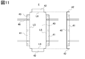
外蓋体4は、箱体2の開口を外側から覆うための部材である。外蓋体4は、板40と、左右一対の板41と、上下一対の板42とを有する。板40は、上下に長い長方形状に形成されている。2つの板41は、それぞれ、上下方向に長い長方形状に形成されており、板40の左右両端に略垂直に接続されている。2つの板42は、それぞれ、左右方向に長い長方形状に形成されており、板40の上下両端に略垂直に接続されている。板41間の距離は、箱体2の開口の左右(幅)寸法よりも長い。板42間の距離は、箱体2の開口の上下(高さ)寸法よりも長い。
箱体2の両側面には、それぞれ、箱体2の開口側の辺に沿って高さ位置の異なる3箇所に、面ファスナー25が設けられている。また、箱体2の両側面には、それぞれ、開口側の辺に沿って高さ位置の異なる2箇所に、ベルト26(バックルを含む)が取り付けられている。一方、外蓋体4の2つ板41の対向する両内側面には、それぞれ、高さ位置の異なる3箇所に、面ファスナー45が設けられている。また、外蓋体4の2つ板41の両外側面には、それぞれ、高さ位置の異なる2箇所に、ベルト46(バックルを含む)が取り付けられている。外蓋体4の各面ファスナー45を、箱体2の対応する面ファスナー25に係着することで、外蓋体4を箱体2に固定することができる。また、外蓋体4の各ベルト46のバックルを、箱体2の対応するベルト26のバックルに係合することで、外蓋体4を箱体2にさらに強く固定することができる。
なお、箱体2の両側面には、それぞれ、高さ位置の異なる2箇所に、把手27が設けられている。また、箱体2の上下面には、それぞれ、左右の2箇所に、把手27が設けられている。また、内蓋体3の板部30の前面上部には、左右にそれぞれ上下2つの把手37が設けられている。
また、包装体1は、傾斜板5を有する。傾斜板5は、箱体2の内から外へ又は外から内へロボットRを移動するために使用される。傾斜板5は、箱体2に対して着脱自在である。使用の際には、傾斜板5の一端は、例えば面ファスナーにより、箱体2の開口の下辺付近に係着され、他端は、床に載せられる。梱包の際には、傾斜板5は、立てた状態で、内蓋体3の下部に設けられる凹部に収納される(図2の左下図参照)。
また、箱体2には、背面左下部に開口6が設けられている(図3、図4参照)。開口6は、箱体2内の左下部に設けられた内部スペースに通じている。当該内部スペースには、ロボットRに付属する取扱説明書、充電器、ケーブル、器具等の付属品を収納するためのケースCが格納される。なお、箱体2は、開口6を開閉自在な扉を有する。
また、箱体2には、背面中央下部に開口7が設けられている(図3、図4参照)。開口7は、箱体2内に通じている。ロボットRが格納された状態では、開口7を通じてロボットRの後側にアクセス可能である。開口7を用いることで、例えば、包装体1内のロボットRに外部から電源ケーブルを接続して電源供給することができる。なお、箱体2は、開口7を開閉自在な扉を有する。
また、箱体2は、下側面の4隅に4つのキャスター8を有する。キャスター8の1つ以上は、車輪の回転を停止可能なストッパーを有していてもよい。
図4に示すロボットRは、双腕人型のロボットである。ロボットRは、頭部R1と、胴部R2と、脚部R3と、左右一対の腕部R4と、操作パネルR5とを有する。操作パネルR5は、胴部R2の前面に取り付けられている。このロボットRは、例えば、首、肩、腕、手首、指、腰、脚等の箇所に多数の関節を有する。これらの関節によって各部を様々な姿勢に動作させることが可能である。従って、例えば、電源オフ状態において各関節がロックされていない場合には、ロボットRは、関節が自由に動いて一定の体勢を維持できず(脱力したような状態になり、直立した通常体勢を維持できない)、揺れや傾きによって倒れ、損傷するおそれがある。そこで、本実施形態の包装体1は、後側緩衝部21と前側緩衝部31によって、ロボットRを前後から挟んで保持するとともに、外蓋体4によって内蓋体3及び前側緩衝部31の前後方向の位置を固定する。これにより、ロボットRを通常体勢に近い体勢で保持する。なお、操作パネルR5と胴部R2の間には、緩衝部材9を挟み込んでもよい。
包装体1からロボットRを開梱する手順の一例を説明する。まず、作業者は、外蓋体4を箱体2から外す。次に、作業者は、傾斜板5とともに内蓋体3を箱体2から外す。また、作業者は、緩衝部材9をロボットRから外す。次に、作業者は、傾斜板5を箱体2の開口下部に装着する。最後に、作業者は、ロボットRを抱きかかえて、傾斜板5上を滑らせながら、外に引き出す。
包装体1にロボットRを梱包する手順の一例を説明する。まず、作業者は、傾斜板5を箱体2の開口下部に装着する。次に、作業者は、ロボットRを抱きかかえて、傾斜板5上を滑らせながら箱体2内に入れ、後側緩衝部21に嵌めこむ。次に、作業者は、緩衝部材9をロボットRに取り付ける。次に、作業者は、内蓋体3を箱体2に挿入し、前側緩衝部31をロボットRの前側に嵌めこむ。次に、傾斜板5を箱体2から外し、内蓋体3の下側に収納する。最後に、作業者は、外蓋体4を箱体2に装着する。
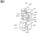
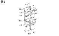
図5は、後側緩衝部21の斜視図である。図6は、前側緩衝部31の斜視図である。
後側緩衝部21は、複数の板状の緩衝部材を有する。後側緩衝部21は、縦緩衝部材210と、横緩衝部材211と、横緩衝部材212と、左右一対の横緩衝部材213と、左右一対の支持部材214と、横緩衝部材215と、横緩衝部材216と、横緩衝部材217と、左右一対の側面緩衝部材218(右側は図示せず、図2の上図を参照)と、緩衝部材219と、下面緩衝部材220とを有する。各横緩衝部材と下面緩衝部材220は、間隔を空けて異なる高さ位置に配置される。
前側緩衝部31は、複数の板状の緩衝部材を有する。前側緩衝部31は、縦緩衝部材310と、横緩衝部材311と、横緩衝部材312と、横緩衝部材315と、横緩衝部材316と、左右一対の前面緩衝部材317とを有する。各横緩衝部材は、間隔を空けて異なる高さ位置に配置される。
図7は、各緩衝部材の関係を説明する図である。図7は、位置が高いものから上から順に、各横緩衝部材の平面図を示している。また、図7は、各縦緩衝部材の側面図を示している。また、図7は、支持部材214の側面図を示している。また、図7は、左の側面緩衝部材218と緩衝部材219の側面図を示している。また、各緩衝部材(支持部材214を含む)は、対応するアルファベット小文字(a~m)で示す箇所(一点鎖線)で、他の緩衝部材と略直交するように嵌め合せ構造により組み合わせられる。
縦緩衝部材210の前面(図7の左)は、ロボットRの後面の横方向中央部に当接するように、当該中央部の形状に沿うように形成されている。また、縦緩衝部材210は、上部に挟持部2101を有する。挟持部2101は、ロボットRの頭部R1の後面から頭頂部を経て頭部R1の前面上部(例えば額部)まで延びている。挟持部2101の先端部は、下方に張り出しており、頭部R1の前面上部に当接する。挟持部2101は、ロボットRの頭部R1が前方に傾くのを抑制するように、頭部R1を前後方向から挟持することができる。
縦緩衝部材310の前面(図7の右)は、ロボットRの前面の横方向中央部に当接するように、当該中央部の形状に沿うように形成されている。
横緩衝部材211と横緩衝部材311は、ロボットRの頭部R1の高さに配置され、頭部R1の前後左右方向の動作を抑制するように挟持する。横緩衝部材211の中央部は、頭部R1の側面及び後面に当接するように、頭部R1の側面及び後面に沿うように形成されている。また、横緩衝部材211には、頭部R1を左右方向から挟む挟持部2111が形成されている。また、横緩衝部材211は、横緩衝部材311の左右一対の凹部3112に係合させるための左右一対の凸部2112を有する。横緩衝部材311の中央部は、頭部R1の前面に当接するように、頭部R1の前面に沿うように形成されている。また、横緩衝部材311は、横緩衝部材211の左右一対の凸部2112を受けて挟むことにより係合する左右一対の凹部3112を有する。
横緩衝部材212と横緩衝部材312は、ロボットRの胴部R2上部及び肩部の高さに配置され、胴部R2上部及び肩部の前後左右方向の動作を抑制するように挟持する。横緩衝部材212の中央部は、胴部R2上部及び肩部の側面及び後面に当接するように、胴部R2上部及び肩部の側面及び後面に沿うように形成されている。また、横緩衝部材212には、肩部を左右方向から挟む挟持部2121が形成されている。横緩衝部材312の中央部は、胴部R2上部(操作パネルR5を含む)の側面及び前面に当接するように、胴部R2上部の側面及び前面に沿うように形成されている。また、横緩衝部材312は、横緩衝部材212の左右一対の挟持部2121を受ける左右一対の凹部3121を有する。挟持部2121と凹部3121は、互いに係合する構造としてもよい。
横緩衝部材213は、ロボットRの腕部R4上部の高さに配置され、腕部R4上部の前後左右方向の動作を抑制するように挟持する。横緩衝部材213の中央部は、腕部R4上部の側面及び後面に当接するように、腕部R4上部の側面及び後面に沿うように形成されている。また、横緩衝部材213には、腕部R4上部を左右方向から挟む挟持部2131が形成されている。
支持部材214は、横緩衝部材212及び横緩衝部材215の間に配置され、その上下端において横緩衝部材212及び横緩衝部材215に固定される。また、支持部材214の前面の中央部には、横緩衝部材213が固定される。
横緩衝部材215と横緩衝部材315は、ロボットRの脚部R3上部及び腕部R4下部(例えば手首)の高さに配置され、脚部R3上部及び腕部R4下部の前後左右方向の動作を抑制するように挟持する。横緩衝部材215の中央部は、脚部R3上部の側面及び後面に当接するように、脚部R3上部の側面及び後面に沿うように形成されている。また、横緩衝部材215には、左右一対の腕部R4下部を挟持する左右一対の挟持部2151が形成されている。横緩衝部材315の中央部は、脚部R3上部の側面及び前面に当接するように、脚部R3上部の側面及び前面に沿うように形成されている。また、横緩衝部材315は、横緩衝部材215の左右一対の挟持部2151に挿入するための左右一対の凸部3151を有する。挟持部2151と凸部3151は、互いに係合する構造としてもよい。
横緩衝部材216と横緩衝部材316は、ロボットRの脚部R3中段部の高さに配置され、脚部R3中段部の前後左右方向の動作を抑制するように挟持する。横緩衝部材216の中央部は、脚部R3中段部の側面及び後面に当接するように、脚部R3中段部の側面及び後面に沿うように形成されている。横緩衝部材316の中央部は、脚部R3中段部の側面及び前面に当接するように、脚部R3中段部の側面及び前面に沿うように形成されている。
横緩衝部材217は、ロボットRの脚部R3下部(例えば足)の高さに配置され、脚部R3下部の前後左右方向の動作を抑制するように挟持する。横緩衝部材217の中央部は、脚部R3下部の側面及び後面に当接するように、脚部R3下部の側面及び後面に沿うように形成されている。また、横緩衝部材217には、脚部R3下部を左右方向から挟む挟持部2171が形成されている。
横緩衝部材217と左右一対の前面緩衝部材317は、ロボットRの脚部R3下部の高さに配置され、脚部R3下部を前後方向から挟持する。
左側面緩衝部材218及び右側面緩衝部材218は、ロボットRの脚部R3下部の高さに配置され、脚部R3下部を左右方向から挟持する。左側面緩衝部材218は、箱体2の左側壁の内面下部前方に装着されるとともに、横緩衝部材217の左側部に係合される。右側面緩衝部材218は、箱体2の右側壁の内面下部前方に装着される。
緩衝部材219は、横緩衝部材217の右側部に係合される。緩衝部材219と箱体2の右側壁の間に、ケースCを収納するための内部スペースが設けられる。
下面緩衝部材220は、ロボットRの脚部R3の底面を下側から持ち上げるようにして支持する。脚部R3の底面に設けられた車輪が、箱体2の床から離れるように持ち上がるのが望ましい。下面緩衝部材220は、前後方向に長い略直方体であり、その前後面は上面に向かって傾斜している。これにより、ロボットRに上方向の力が加わり、箱体2の床から脚部R3の底面に設けられた車輪に伝わる振動を減少させることができる。また、前後の傾斜面により、ロボットRを前後方向に移動させる際に、下面緩衝部材220の上をロボットRを滑らかに通過させることができる。
なお、後側緩衝部21及び前側緩衝部31には、例えば発泡スチロール等の発泡プラスチックを用いることができる。
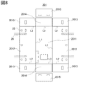
図8は、箱体2を構成する外板部201の展開図である。図9は、箱体2を構成する内板部202の展開図である。箱体2の壁部20は、外板部201と、内板部202とから構成される。
外板部201は、背面板2011と、左右一対の側板2012と、2組の上下一対の板2013と、上下一対の板2014と、上下一対の板2015とを有する。2つの側板2012は、背面板2011の左右に接続されており、L1で略垂直に曲げられることで壁部20の左右壁を構成する。左の2つの板2013は、左の側板2012の上下に接続されており、L2で略垂直に曲げられることで壁部20の左側の上下壁を構成する。右の2つの板2013は、右の側板2012の上下に接続されており、L2で略垂直に曲げられることで壁部20の右側の上下壁を構成する。2つの板2014は、背面板2011の上下に接続されており、L3で略垂直に曲げられることで壁部20の背面側の上下壁を構成する。板2014は、板2013よりも外側に配置される。2つの板2015は、壁部20の正面側の上下壁を構成する。板2015は、板2013よりも外側に配置される。
外板部201には、例えば、プラスチック製の段ボールを用いることができる。各板の対向する面は、例えば、超音波溶接、熱溶接、接着剤などにより貼り合わせることができる。
内板部202は、背面板2021と、左右一対の側板2022とを有する。2つの側板2022は、背面板2021の左右に接続されており、L4で略垂直に曲げられることで壁部20の左右壁を構成する。内板部202は、外板部201の内側に配置される。すなわち、背面板2021は、背面板2011の内側に配置され、左右の側板2022は、左右の側板2012の内側に配置される。なお、背面板2021の下部には、開口6に対応する開口と、開口7に対応する開口とが形成されている。
また、背面板2021の内側下部には、補強板2023が配置される。補強板2023には、開口6に対応する開口と、開口7に対応する開口とが形成されている。
内板部202には、例えば、プラスチック製の段ボールを用いることができる。内板部202の各板と対応する外板部201の各板は、例えば、超音波溶接、熱溶接、接着剤などにより貼り合わせることができる。また、背面板2021と補強板2023とは、例えば、超音波溶接、熱溶接、接着剤などにより貼り合わせることができる。なお、正面側の開口の縁部(2枚の板が重なっている)には、例えば、金属あるいや樹脂製の枠体を嵌め込んでもよい。
図10は、内蓋体3及び傾斜板5の正面図である。図10は、内蓋体3及び傾斜板5の右側面図も示している。図10は、内蓋体3の前側緩衝部31を省略し、板部30を示している。
板部30は、上側板301と、下側板302とを有する。上側板301の下端部は、下側板302の上端部と、直方体状の連結部材303を介して連結されている。上側板301と下側板302は、連結部材303により前後方向に段差を付けて連結されている。下側板302の前面下端部には、直方体状の受け部材304が装着されている。連結部材303、下側板302、及び受け部材304により形成された凹状のスペース(中間スペース)に、傾斜板5を立てて収納することができる。
傾斜板5の先端部51は、床に接する面積が大きくなるように鋭角に形成されている。傾斜板5の下面の先端部51と反対側には、面ファスナー55が設けられている。面ファスナー55を、下側板302の前面に設けられている面ファスナー35に係着することで、傾斜板5を内蓋体3に固定することができる。また、面ファスナー55を、箱体2の開口の下辺付近に設けられている面ファスナーに係着することで、傾斜板5を箱体2に固定することができる(図1等参照)。
図11は、外蓋体4の展開図である。図11は、外蓋体4の右側面図も示している。
外蓋体4は、図1で説明したように、板40と、左右一対の板41と、上下一対の板42とを有する。2つの板41は、板40の左右に接続されており、L5で略垂直に曲げられることで外蓋体4の左右端部を構成する。2つの板42は、板40の上下に接続されており、L6で略垂直に曲げられることで外蓋体4の上下端部を構成する。
外蓋体4には、例えば、プラスチック製の段ボールを用いることができる。2つの板41は、L5を軸に揺動自在となるように加工される。2つの板42は、折り曲げた状態で固定されるように、例えば、超音波や熱により曲げ加工される。略垂直に固定された上側の板42により、外蓋体4を箱体2の開口に引っ掛けることができるので、作業者は、左右の板41を箱体2に固定する作業を効率的に行うことができる。
図12は、操作パネルR5用の緩衝部材9の六面図である。図12は、緩衝部材9の正面(a)、左側面(b)、右側面(c)、平面(d)、背面(e)、底面(f)を示している。また、図12は、緩衝部材9の斜視図も示している。
緩衝部材9は、上述したように、操作パネルR5の背面と胴部R2の前面の間に挟み込まれる。緩衝部材9は、板91と、板92とを有する。正面視した場合に、板91の中央部は、操作パネルR5と胴部R2の接続部に当接するように、当該接続部の下面及び側面に沿うように形成されている。また、板91には、当該接続部を左右方向から挟み、接続部の上面に引っ掛ける挟持部911が形成されている。板92は、板91の下端部に胴部R2の方向に略垂直に接続されている。板92の中央部は、胴部R2の前面左右方向に当接するように、胴部R2の前面左右方向の形状に沿うように形成されている。
以上、本発明の実施形態について説明した。本実施形態の包装体1は、ロボット等の電子機器の梱包及び開梱の作業性を向上でき、かつ、繰り返し利用できる。
例えば、包装体1は、正面側に開口を有し、内蓋体3と外蓋体4により開閉される。これにより、作業者はロボットRを持ち上げずに梱包又は開梱できるため、作業性を向上することができる。また例えば、包装体1は、梱包又は開梱の際に破壊されないため、繰り返し利用することができる。
また例えば、後側緩衝部21は、ロボットRの各部を挟持する緩衝部材を有する。これにより、ロボットRを後側緩衝部21に対して簡単に固定することができるとともに、輸送中の揺れによるロボットRの動きを抑制して保護することができる。また例えば、後側緩衝部21は、前側緩衝部31とともに、ロボットRの各部を前後から挟む。これにより、輸送中の揺れによるロボットRの動きをより強く抑制することができる。
また例えば、後側緩衝部21は、ロボットRの脚部R3の底面を下側から持ち上げるようにして支持する下面緩衝部材220を有する。これにより、箱体2の床から脚部R3の底面に設けられた車輪に伝わる振動を減少させることができる。
また例えば、箱体2は、内部にケースCを収納する内部スペースを有し、また、背面に開口6を有する。これにより、正面側の2つの蓋体を外さなくても、充電器等を収納したケースCを箱体2に簡単に出し入れすることができる。また例えば、箱体2は、背面に開口7を有する。これにより、ロボットRを箱体2に格納した状態で、ロボットRに電源ケーブルや通信ケーブル等のケーブルを接続して、充電や設定を行うことができる。
上述の実施形態の変形例について、図面を参照して説明する。以下では、上述の実施形態と異なる点を中心に説明する。
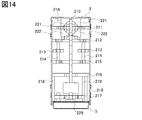
図13は、本発明の実施形態の変形例に係る後側緩衝部21Aの斜視図である。図14は、後側緩衝部21Aの正面図である。図14は、箱体2と傾斜板5も示している。
本変形例の後側緩衝部21Aは、上述の実施形態の後側緩衝部21の有する各緩衝部材に加えて、左右一対の緩衝部材221と、左右一対の緩衝部材222とを有する。左右の緩衝部材221は、横緩衝部材211の上面の、縦緩衝部材210の左右両側に対称に設置される。左右の緩衝部材222は、横緩衝部材211の下面の、縦緩衝部材210の左右両側に設置される。左右の緩衝部材221は対称に構成されるため、また、左右の緩衝部材222は対称に構成されるため、以下では、左側の緩衝部材221及び緩衝部材222について説明する。
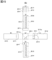
図15は、頭部R1の上側用の緩衝部材221の六面図である。図15は、緩衝部材221の正面(a)、左側面(b)、右側面(c)、平面(d)、背面(e)、底面(f)を示している。ハッチングは、貫通している部分を表している。
緩衝部材221は、前後に長い略直方体に形成される。緩衝部材221は、板2211と、板2212と、板2213と、板2214とを有する。板2211は、正面側に配置される。板2212は、板2211の後面の右側に、後方向に略垂直に接続される。板2213は、板2211の後面の左側に、後方向に略垂直に接続される。板2212と板2213は、それらの後端部において、板2214によって接続される。
板2211の右下部には、ロボットRの頭部R1の側面中央部から頭頂部に架けて当接するように、面2211aが形成されている。板2212の前側下部には、頭部R1の後面中央部やや左側から頭頂部のやや左側に架けて当接するように、面2212aが形成されている。
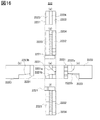
図16は、頭部R1の下側用の緩衝部材222の六面図である。図16は、緩衝部材222の正面(a)、左側面(b)、右側面(c)、平面(d)、背面(e)、底面(f)を示している。ハッチングは、貫通している部分を表している。
緩衝部材222は、前後に長い略直方体に形成される。緩衝部材222は、板2221と、板2222と、板2223と、板2224とを有する。板2221は、正面側に配置される。板2222は、板2221の後面の右側に、後方向に略垂直に接続される。板2223は、板2221の後面の左側に、後方向に略垂直に接続される。板2222と板2223は、それらの後端部において、板2224によって接続される。
板2221の右上部には、ロボットRの頭部R1の側面中央部から首部に架けて当接するように、面2221aが形成されている。板2221の下部には、ロボットRの首部の側面中央部から肩部の上面に架けて当接するように、面2221bが形成されている。板2222の前側上部には、頭部R1の後面中央部やや左側から首部のやや左側に架けて当接するように、面2222aが形成されている。板2222の前側下部には、ロボットRの左肩部を避けるように、面2222bが形成されている。板2223の前側の下部には、ロボットRの左肩部を避けるように、面2223bが形成されている。
左右の緩衝部材221と左右の緩衝部材222により、ロボットRの頭部R1は上下左右から囲まれるため、頭部R1の上下左右の動きを抑制することができる。また、左右の緩衝部材221と左右の緩衝部材222により、頭部R1の後面が受け止められるため、後ろ方向への動きを抑制することができる。
以上、本発明の実施形態について説明した。上記の本発明の実施形態は、本発明の要旨と範囲を例示することを意図し、限定するものではない。本発明は、本発明の要旨の範囲内で種々の変形実施が可能である。
なお、各実施形態や各変形例の包装体1の各部材の寸法、形状等は、本発明の目的を達成できれば、図示した例に限られない。包装体1の各部材の寸法や形状は、梱包する対象物に応じて適宜決定されればよい。
本発明は、包装体、当該包装体を梱包方法等の様々な態様によって提供することができる。本発明は、ロボットに限られず、ジョイント、ヒンジ等の可動部を有する様々な電子機器に用いることができる。
1…包装体、2…箱体、3…内蓋体、4…外蓋体、5…傾斜板、6…開口、7…開口、8…キャスター、9…緩衝部材、20…壁部、21…後側緩衝部、21A…後側緩衝部、25…面ファスナー、26…ベルト、27…把手、30…板部、31…前側緩衝部、35…面ファスナー、37…把手、40…板、41…板、42…板、45…面ファスナー、46…ベルト、51…先端部、55…面ファスナー、91…板、92…板、201…外板部、202…内板部、210…縦緩衝部材、211…横緩衝部材、212…横緩衝部材、213…横緩衝部材、214…支持部材、215…横緩衝部材、216…横緩衝部材、217…横緩衝部材、218…側面緩衝部材、219…緩衝部材、220…下面緩衝部材、221…緩衝部材、222…緩衝部材、301…上側板、302…下側板、303…連結部材、304…受け部材、310…縦緩衝部材、311…横緩衝部材、312…横緩衝部材、315…横緩衝部材、316…横緩衝部材、317…前面緩衝部材、911…挟持部、2011…背面板、2012…側板、2013…板、2014…板、2015…板、2021…背面板、2022…側板、2023…補強板、2101…挟持部、2111…挟持部、2112…凸部、2121…挟持部、2131…挟持部、2151…挟持部、2171…挟持部、2211…板、2211a…面、2212…板、2212a…面、2213…板、2214…板、2221…板、2221a…面、2221b…面、2222…板、2222a…面、2222b…面、2223…板、2223b…面、2224…板、3112…凹部、3121…凹部、3151…凸部、C…ケース、R…ロボット、R1…頭部、R2…胴部、R3…脚部、R4…腕部、R5…操作パネル
Claims (12)
- 可動部を有する電子機器用の包装体であって、
前面に開口が設けられた箱体と、
前記箱体内に収納される前記電子機器を前記箱体の前面側から覆う、前記箱体に着脱自在な内蓋体と、
前記箱体の外側から前記開口を覆う、前記箱体に着脱自在な外蓋体と、を備え、
前記箱体は、前記電子機器の後面側を受ける複数の後側緩衝部材を有し、
前記内蓋体は、前記電子機器の前面側を受ける複数の前側緩衝部材を有する
包装体。 - 請求項1に記載の包装体であって、
前記後側緩衝部材の少なくとも1つは、前記可動部の前方への動きを抑制するように前記可動部を挟持する挟持部を有する
包装体。 - 請求項1に記載の包装体であって、
前記電子機器は、頭部、胴部、腕部、及び脚部を含むロボットであり、
前記後側緩衝部材の少なくとも1つは、前記頭部の前方への動きを抑制するように前記頭部を挟持する挟持部を有する
包装体。 - 請求項3に記載の包装体であって、
前記後側緩衝部材のうち少なくとも1つは、前記腕部の前方への動きを抑制するように前記腕部を挟持する挟持部を有する
包装体。 - 請求項3に記載の包装体であって、
前記後側緩衝部材は、前記箱体の内部底面に設けられ、前記脚部を上方向に持ち上げるように前記脚部を支持する緩衝部材を含む
包装体。 - 請求項1に記載の包装体であって、
前記後側緩衝部材及び前記前側緩衝部材の少なくとも1組は、互いに向かい合って係合することにより前記可動部を前後から挟む係合構造を有する
包装体。 - 請求項1に記載の包装体であって、
前記複数の後側緩衝部材は、縦方向に延びて前記電子機器の後面中央部を受ける縦緩衝部材と、前記縦緩衝部材と交差して横方向に延びて前記電子機器の後面を受ける複数の横緩衝部材とを含み、
前記複数の前側緩衝部材は、縦方向に延びて前記電子機器の前面中央部を受ける縦緩衝部材と、前記縦緩衝部材と交差して横方向に延びて前記電子機器の前面を受ける複数の横緩衝部材とを含み、
前記後側の複数の横緩衝部材及び前記前側の複数の横緩衝部材は、間隔を空けて複数の高さ位置に配置され、各高さ位置において互いに向かい合って前記電子機器を前後から挟み、
前記後側の横緩衝部材及び前記前側の横緩衝部材の少なくとも1組は、互いに向かい合って係合することにより前記可動部を前後から挟む係合構造を有する
包装体。 - 請求項1に記載の包装体であって、
前記外蓋体は、前記開口を覆う第1の板と、前記第1の板の上下端に前記箱体側に折り曲げた状態で固定された1組の第2の板を有し、前記第2の板間の距離は、前記開口の上下寸法よりも大きい
包装体。 - 請求項1に記載の包装体であって、
前記箱体は、後面に、前記開口よりも小さい第2の開口と、前記第2の開口を開閉自在な扉とを有する
包装体。 - 請求項1に記載の包装体であって、
前記箱体は、前記電子機器に付属する器具を収納するケースを格納する内部スペースを有し、後面に前記内部スペースにアクセスするための前記開口よりも小さい第3の開口を有する
包装体。 - 請求項1に記載の包装体であって、
前記開口の下部に着脱可能な傾斜板を備え、
前記内蓋体は、上側板と、前記上側板の下端に段差を付けて連結された下側板とを有し、
前記内蓋体を前記箱体に収納しかつ前記外蓋体で前記開口を覆った状態で、前記外蓋体と前記段差と前記下側板とにより囲まれる、前記傾斜板を収納するための中間スペースを有する
包装体。 - 請求項1に記載の包装体であって、
前記箱体は、背面および左右側面の壁に対応する板を含む外板部と、背面および左右側面の壁に対応する板を含む内板部とを有し、
前記箱体の背面および左右側面の壁は、前記外板部と前記内板部とを重ねて貼り合わせることで形成される
包装体。
Applications Claiming Priority (2)
| Application Number | Priority Date | Filing Date | Title |
|---|---|---|---|
| JP2016124398A JP6307560B2 (ja) | 2016-06-23 | 2016-06-23 | 包装体 |
| JP2016-124398 | 2016-06-23 |
Publications (1)
| Publication Number | Publication Date |
|---|---|
| WO2017221598A1 true WO2017221598A1 (ja) | 2017-12-28 |
Family
ID=60784432
Family Applications (1)
| Application Number | Title | Priority Date | Filing Date |
|---|---|---|---|
| PCT/JP2017/018801 Ceased WO2017221598A1 (ja) | 2016-06-23 | 2017-05-19 | 包装体 |
Country Status (2)
| Country | Link |
|---|---|
| JP (1) | JP6307560B2 (ja) |
| WO (1) | WO2017221598A1 (ja) |
Families Citing this family (2)
| Publication number | Priority date | Publication date | Assignee | Title |
|---|---|---|---|---|
| JP2020183256A (ja) * | 2019-05-08 | 2020-11-12 | 株式会社アイベックス | 収容スタンド |
| CN112623476B (zh) * | 2020-12-04 | 2022-11-01 | 浙江同济科技职业学院 | 智能机器人的防摆动辅助运输装置 |
Citations (5)
| Publication number | Priority date | Publication date | Assignee | Title |
|---|---|---|---|---|
| JPS6010788U (ja) * | 1983-06-30 | 1985-01-24 | 三菱電機株式会社 | ロボツトの梱包体 |
| JPH0232973A (ja) * | 1988-07-22 | 1990-02-02 | Mitsubishi Electric Corp | 包装用緩衝材 |
| JPH10211955A (ja) * | 1997-01-30 | 1998-08-11 | Sekisui Plastics Co Ltd | 緩衝包装材及び集合包装体 |
| JP2002211649A (ja) * | 2001-01-23 | 2002-07-31 | Honda Express Co Ltd | コンテナー |
| JP2005024832A (ja) * | 2003-07-01 | 2005-01-27 | Fuji Photo Film Co Ltd | 感光材料用遮光箱 |
-
2016
- 2016-06-23 JP JP2016124398A patent/JP6307560B2/ja active Active
-
2017
- 2017-05-19 WO PCT/JP2017/018801 patent/WO2017221598A1/ja not_active Ceased
Patent Citations (5)
| Publication number | Priority date | Publication date | Assignee | Title |
|---|---|---|---|---|
| JPS6010788U (ja) * | 1983-06-30 | 1985-01-24 | 三菱電機株式会社 | ロボツトの梱包体 |
| JPH0232973A (ja) * | 1988-07-22 | 1990-02-02 | Mitsubishi Electric Corp | 包装用緩衝材 |
| JPH10211955A (ja) * | 1997-01-30 | 1998-08-11 | Sekisui Plastics Co Ltd | 緩衝包装材及び集合包装体 |
| JP2002211649A (ja) * | 2001-01-23 | 2002-07-31 | Honda Express Co Ltd | コンテナー |
| JP2005024832A (ja) * | 2003-07-01 | 2005-01-27 | Fuji Photo Film Co Ltd | 感光材料用遮光箱 |
Also Published As
| Publication number | Publication date |
|---|---|
| JP6307560B2 (ja) | 2018-04-04 |
| JP2017226452A (ja) | 2017-12-28 |
Similar Documents
| Publication | Publication Date | Title |
|---|---|---|
| JP6307560B2 (ja) | 包装体 | |
| JP5952855B2 (ja) | 梱包具 | |
| JP2009035269A (ja) | 梱包構造 | |
| CN103339036B (zh) | 可再利用容器 | |
| JP2010254370A (ja) | 位置決め板及びこれを用いた電気機器の梱包装置 | |
| JP4364746B2 (ja) | 梱包用箱 | |
| JP2011011562A (ja) | 搭載用治具および昇降リフト | |
| JP3101993U (ja) | 緩衝包装具 | |
| JP3181294U (ja) | 折曲板体と可撓性フィルムとを組み合わせた緩衝部材 | |
| JP2018034883A (ja) | 梱包箱、テレビジョン装置、及び梱包方法 | |
| JP5409512B2 (ja) | 包装ケース | |
| JP6206993B2 (ja) | 梱包具 | |
| JP5486117B1 (ja) | 収容容器 | |
| JPH0546780U (ja) | 梱包装置 | |
| JP4336144B2 (ja) | 梱包装置 | |
| JPH0443497Y2 (ja) | ||
| JP2012101826A (ja) | 梱包装置 | |
| JP2000109059A (ja) | 梱包材 | |
| JP6078603B1 (ja) | 梱包ケース | |
| JP2007069938A (ja) | 梱包箱 | |
| JP2008222257A (ja) | 梱包材 | |
| JP2015229517A (ja) | ロボット梱包容器 | |
| JP2924197B2 (ja) | アイロンの包装装置 | |
| JPH0237727Y2 (ja) | ||
| JP2005145458A (ja) | 包装箱 |
Legal Events
| Date | Code | Title | Description |
|---|---|---|---|
| 121 | Ep: the epo has been informed by wipo that ep was designated in this application |
Ref document number: 17815067 Country of ref document: EP Kind code of ref document: A1 |
|
| NENP | Non-entry into the national phase |
Ref country code: DE |
|
| 122 | Ep: pct application non-entry in european phase |
Ref document number: 17815067 Country of ref document: EP Kind code of ref document: A1 |