WO2017221422A1 - 吸収性物品の製造方法 - Google Patents
吸収性物品の製造方法 Download PDFInfo
- Publication number
- WO2017221422A1 WO2017221422A1 PCT/JP2016/068918 JP2016068918W WO2017221422A1 WO 2017221422 A1 WO2017221422 A1 WO 2017221422A1 JP 2016068918 W JP2016068918 W JP 2016068918W WO 2017221422 A1 WO2017221422 A1 WO 2017221422A1
- Authority
- WO
- WIPO (PCT)
- Prior art keywords
- nonwoven fabric
- web
- stretching
- elastomer member
- absorbent article
- Prior art date
Links
Images


Classifications
-
- A—HUMAN NECESSITIES
- A61—MEDICAL OR VETERINARY SCIENCE; HYGIENE
- A61F—FILTERS IMPLANTABLE INTO BLOOD VESSELS; PROSTHESES; DEVICES PROVIDING PATENCY TO, OR PREVENTING COLLAPSING OF, TUBULAR STRUCTURES OF THE BODY, e.g. STENTS; ORTHOPAEDIC, NURSING OR CONTRACEPTIVE DEVICES; FOMENTATION; TREATMENT OR PROTECTION OF EYES OR EARS; BANDAGES, DRESSINGS OR ABSORBENT PADS; FIRST-AID KITS
- A61F13/00—Bandages or dressings; Absorbent pads
- A61F13/15—Absorbent pads, e.g. sanitary towels, swabs or tampons for external or internal application to the body; Supporting or fastening means therefor; Tampon applicators
Definitions
- the present invention relates to a method for manufacturing an absorbent article.
- the absorbent article includes, for example, an absorbent main body and a pair of side flaps extending outward from both end portions in the width direction of the absorbent main body.
- Patent Document 1 Japanese Patent Publication No. 11-506037 discloses a method for manufacturing a side panel (side flap) of a disposable diaper.
- the laminate member which is a material for side flaps, is stretched to manufacture a side panel having stretchability in the width direction.
- the laminate member include a member in which a sheet (nonwoven fabric) and an elastomer member are laminated.
- Patent Document 1 in order to sufficiently impart stretchability to the side flap, a laminate member, that is, a member in which a nonwoven fabric and an elastomer member are closely adhered to each other is stretched.
- the elastomer member since the elastomer member has a certain degree of extensibility, it can be extended following the above-described stretching process.
- the nonwoven fabric since the nonwoven fabric has almost no extensibility, it cannot follow the above-mentioned stretching treatment so much and cannot stretch as much as an elastomer member.
- the elastomer member and the non-woven fabric are also different in how to stretch by stretching treatment (whether they are stretched approximately evenly or whether the degree of stretching is different in each part).
- the nonwoven fabric cannot follow the elongation of the elastomer member, and the nonwoven fabric may be weakened or partially cut. If a side flap using such a nonwoven fabric and an elastomer member is applied to an absorbent article, when the side flap is greatly extended during use of the absorbent article, the side flap is cut or stretched to the side flap. There is a risk that it may be difficult to use due to a loss of feeling. Therefore, such a side flap cannot be applied to an absorbent article, resulting in a manufacturing defect.
- An object of the present invention is to produce a side flap excellent in elongation by suppressing weakening and cutting of a nonwoven fabric when forming a side flap in which an elastomer member and a nonwoven fabric are laminated in a method for producing an absorbent article having a side flap. It is providing the manufacturing method of the absorbent article which can be formed.
- the manufacturing method of the absorbent article of the present invention is as follows. (1) An absorbent main body and a pair of side flaps extending outward from both end portions in the width direction of the absorbent main body, each of the pair of side flaps being laminated on the nonwoven fabric and the nonwoven fabric. A non-woven fabric material for nonwoven fabric that has been subjected to a first gear stretching process in advance, and is partially joined to the elastomer member in a stretchable manner.
- the material nonwoven fabric subjected to the first gear stretching process in advance is partially joined to the elastomer member so as to be stretchable. That is, the material nonwoven fabric which has been loosened in advance and imparted with extensibility is partially joined to the elastomer member so as to be extensible (not entirely). Therefore, when the second gear stretching process is performed, the material nonwoven fabric can be stretched very easily as compared with the case where the material nonwoven fabric is suddenly stretched together with the elastomer member.
- the material non-woven fabric can be stretched according to its own characteristics, but partially follows the stretch of the elastomer member, but does not completely follow, even if the stretch method is somewhat different from that of the elastomer member. Due to these synergistic effects, the laminate can be appropriately stretched as a whole. That is, in the second gear stretching step, the material nonwoven fabric can follow the stretching treatment and can be stretched without weakening or cutting even if a sufficient stretching treatment is performed to impart stretchability to the side flaps. Thereby, when forming a side flap, weakening and cutting
- Each of the pair of side flaps further includes another nonwoven fabric laminated on the elastomer member from a side opposite to the nonwoven fabric, and the forming step includes:
- the other material nonwoven fabric for the other nonwoven fabric subjected to the third gear stretching treatment in advance is partially joined to the side opposite to the side to be joined to the material nonwoven fabric in the elastomer member so as to be stretchable.
- the manufacturing method of the absorbent article as described in said (1) including the process to perform may be sufficient.
- the other material nonwoven fabric is further bonded to the elastomer member, the other material nonwoven fabric previously subjected to the third gear stretching process is partially bonded to the elastomer member so as to be stretchable. To do.
- the second gear stretching process when the second gear stretching process is performed, other material nonwoven fabrics can be stretched very easily and partially follow the stretching of the elastomeric member as compared with the case of sudden stretching with the elastomeric member. However, it does not follow completely and can expand according to its own characteristics. Accordingly, in the second gear stretching step, the other material nonwoven fabrics can be stretched without weakening or cutting, whereby the laminate as a whole can be stretched appropriately. Moreover, since another material nonwoven fabric is added, the intensity
- the manufacturing method of the absorbent article of this invention is (3) In the said formation process, the said material nonwoven fabric and the said elastomer member are the both ends edge of the said extending direction of the said material nonwoven fabric in the said extending direction of the said elastomer member.
- the elastomer member does not exist on the entire surface of the material nonwoven fabric, and therefore there exists only the material nonwoven fabric. Therefore, compared with the part which the elastomer member and the material nonwoven fabric have overlapped, in the part only of a material nonwoven fabric, thickness becomes small.
- the side flaps can be made more difficult to be weakened and more difficult to be cut, particularly with respect to elongation in the transport direction perpendicular to the stretching direction. That is, weakening and cutting of the nonwoven fabric can be suppressed when forming the side flaps.
- the manufacturing method of the absorbent article of this invention is (4)
- the said material nonwoven fabric and the said elastomer member are the said material nonwoven fabric in the both ends of the conveyance direction orthogonal to the said extending
- the manufacturing method of the absorbent article according to any one of (1) to (3), wherein the absorbent article is bonded so as to exist inside both ends in the conveyance direction.
- the elastomer member does not exist on the entire surface of the material nonwoven fabric, and therefore there exists only the material nonwoven fabric.
- the manufacturing method of the absorbent article of the present invention is (5) any one of the above (1) to (4), wherein in the forming step, the material nonwoven fabric is joined to the elastomer member by welding.
- the manufacturing method of the absorbent article as described in above.
- the elastomer member and the material nonwoven fabric are joined by welding (example: thermal welding, ultrasonic welding) and not joined by an adhesive. Accordingly, it is possible to avoid a situation in which the adhesive oozes out in the stretching process, adheres to the stretching apparatus, adheres to the subsequent elastomer member and the material nonwoven fabric, and inhibits stretchability.
- the material nonwoven fabric can follow the degree of the stretching treatment, so when forming the side flaps, the weakening and cutting of the nonwoven fabric are suppressed. be able to.
- the material nonwoven fabric is joined to the elastomer member, the material is joined by an adhesive.
- the manufacturing method of the absorbent article as described in the item may be sufficient.
- the adhesive eg, hot melt adhesive
- the adhesive also follows the stretching of the elastomer member and the material nonwoven fabric in the stretching process. Can be stretched. Therefore, it is possible to avoid a situation in which the fibers are fixed to each other at the bonding site in the material nonwoven fabric, and the material nonwoven fabric is biased to be stretched to weaken or partially cut the material nonwoven fabric.
- the material nonwoven fabric can follow the degree of the stretching treatment, so when forming the side flaps, the weakening and cutting of the nonwoven fabric are suppressed. be able to.
- the manufacturing method of the absorbent article of the present invention further includes (7) a pre-stretching step in which the first gear stretching treatment is performed in advance on the material nonwoven fabric before the forming step, and in the pre-stretching step, The material nonwoven fabric is conveyed to a pair of stretching rolls, subjected to the first gear stretching process by the pair of stretching rolls, and the feeding speed of the material nonwoven fabric to the first gear stretching process is the pair of stretching rolls.
- the manufacturing method of the absorbent article according to any one of (1) to (6) above, which is faster than the peripheral speed of the drawing roll.
- the strain generated in the material nonwoven fabric is the sum of the strain that the material nonwoven fabric has before the gear stretching process and the strain that occurs when the material nonwoven fabric is bitten by a pair of stretching rolls.
- the strain of the material nonwoven fabric is reduced before the gear stretching process by increasing the feeding speed of the material nonwoven fabric than the peripheral speed of the pair of stretching rolls (overfeed). .
- the amount of distortion generated in the material nonwoven fabric can be reduced, and the influence of distortion due to the gear stretching process can be suppressed. Thereby, when forming a side flap, the weakening and cutting
- the draw ratio of the first gear drawing process is smaller than the draw ratio of the second gear drawing process.
- the present invention in the method for manufacturing an absorbent article having a side flap, when forming a side flap in which an elastomer member and a nonwoven fabric are laminated, weakening and cutting of the nonwoven fabric are suppressed, and a side flap excellent in elongation is formed. It is possible to provide a method for manufacturing an absorbent article that can be used.
- FIG. 1 is a schematic overall view of an absorbent article manufacturing apparatus according to a first embodiment. It is a figure explaining the manufacturing method of the absorbent article which concerns on 1st Embodiment. It is a figure explaining the manufacturing method of the absorbent article which concerns on 1st Embodiment. It is a figure explaining the manufacturing method of the absorbent article which concerns on 1st Embodiment. It is a figure explaining the manufacturing method of the absorbent article which concerns on 1st Embodiment. It is a figure explaining the extending
- FIG. 1 is a view showing an absorbent article 1 (disposable diaper), and shows a plan view in a state where the absorbent article 1 is expanded and expanded.
- the absorbent article 1 has a longitudinal direction L, a width direction W, and a thickness direction T that are orthogonal to each other, a central axis CL that extends in the longitudinal direction L through the center of the width direction W, and the center of the longitudinal direction L. It has a central axis CW extending in the width direction W.
- plan view viewing the absorbent article 1 that has been unfolded and flattened from the upper surface side or the lower surface side in the thickness direction is referred to as “plan view”.
- “Skin side” and “non-skin side” mean a side relatively close to the wearer's skin surface and a side far from the skin surface in the thickness direction of the absorbent article 1 when the absorbent article 1 is worn.
- a direction toward the central axis CL and a direction away from the central axis CL are defined as an inner direction and an outer direction in the width direction W, respectively.
- a direction toward the central axis CW and a direction away from the central axis CW are defined as an inner direction and an outer direction of the longitudinal direction L, respectively.
- the absorbent article 1 In the longitudinal direction L, the absorbent article 1 has a back waistline region S1 corresponding to the waistline of the wearer, a ventral waistline region S2 corresponding to the waistline of the wearer, and the wearer's crotch. Correspondingly, it has a crotch region S3 located between the back waistline region S1 and the abdominal waistline region S2.
- the absorbent article 1 has an absorbent main body AB extending in the longitudinal direction L from the back waistline region S1 to the ventral waistline region S2, and extends outward from both ends in the width direction W of the absorbent main body AB in the backside waistline region S1.
- a pair of side flaps SF1 and SF2 to be taken out, and a pair of engagement tapes 8 and 8 extending outward from the outer ends of the pair of side flaps SF1 and SF2 in the width direction W are provided.
- the pair of side flaps SF1 and SF2 of the pair of side flaps SF1 in the back waistline region S1 is a member to be engaged in the center in the width direction W of the absorbent main body AB in the ventral waistline region S2. 14 is engaged as a diaper.
- the crotch region S3 may be constricted in the width direction W.
- the direction toward the back waistline region S1 and the direction toward the ventral waistline region S2 in the longitudinal direction L are also referred to as a rear side direction and a front side direction, respectively.
- the absorbent article 1 includes a top sheet 2, a back sheet 3, and an absorbent body 4.
- the top sheet 2 is a liquid-permeable sheet located on the skin side of the wearer.
- Examples of the surface sheet 2 include any liquid-permeable sheet such as a liquid-permeable nonwoven fabric or woven fabric, a synthetic resin film having liquid-permeable holes formed therein, or a composite sheet thereof.
- the back sheet 3 is a liquid-impermeable sheet located on the non-skin side of the wearer. Examples of the back sheet 3 include any liquid-impermeable sheet such as a liquid-impermeable nonwoven fabric or synthetic resin film, a composite sheet thereof, or an SMS nonwoven fabric.
- the absorber 4 is a liquid-absorbing and liquid-holding material located between the top sheet 2 and the back sheet 3.
- the absorber 4 include pulp fibers, synthetic fibers, and absorbent polymers.
- the absorber 4 and the top sheet 2 and the back sheet 3 are joined by an adhesive, respectively, and the top sheet 2 and the back sheet 3 are joined by an adhesive at their peripheral portions.
- a known material generally used in the absorbent article 1 for example, a thermoplastic adhesive can be used as an adhesive for bonding between the top sheet 2, the absorber 4 and the back sheet 3, a known material generally used in the absorbent article 1, for example, a thermoplastic adhesive can be used.
- the absorbent article 1 further includes a pair of leak-proof walls 5 and 5, leg stretchable members 6 and 6, and an exterior sheet 9.
- the pair of leak-proof walls 5 and 5 are a pair of side sheets that extend along the longitudinal direction L so as to cover the surfaces on both sides in the width direction W of the top sheet 2 and are spaced apart in the width direction W. .
- the pair of leak-proof walls 5 and 5 are respectively fixed to the outer ends in the width direction W on the surfaces on both sides in the width direction W of the top sheet 2, and end portions on the inner side in the width direction W. Is formed as a free end so as to form a stretchable gather.
- the leg stretchable member 6 is a linear elastic body such as rubber that stretches both sides in the width direction W of the crotch region S3 in contact with the thigh of the wearer in the longitudinal direction L.
- the exterior sheet 9 is disposed on the non-skin side of the back sheet 3 to reinforce the back sheet 3 and improve its feel. In a state of being joined to the non-skin side of the back sheet 3, the pair of leak-proof walls 5 and 5 and their peripheral portions are connected to each other.
- the material of the surface sheet 2 is mentioned as the leak-proof wall 5
- the material of the back surface sheet 3 is mentioned as the exterior sheet 9.
- the absorbent article 1 further includes a stretchable member 11 in the back waistline region S1.
- the elastic member 11 is a sheet-like member such as an elastomer having elasticity in the width direction W, and is disposed between the pair of side flaps SF1 and SF2 in the width direction W and functions as, for example, a waist gather.
- the stretchable member 11 is bonded to any position between the top sheet 2 and the back sheet 3 in the back waistline region S1, the skin side surface of the top sheet 2, and the non-skin side surface of the back sheet 3. It is attached.
- the elastic member 11 is arranged so as to partially overlap or not overlap the absorber 4 in plan view.
- the elastic member 11 is arranged between the top sheet 2 and the back sheet 3 so that the inner part of the elastic member 11 in the longitudinal direction L overlaps the absorber 4 in the thickness direction. Thereby, the fit of the waistline region can be improved when the absorbent article 1 is worn.
- Each of the pair of side flaps SF1 and SF2 extending outward from both ends in the width direction W of the absorbent main body AB includes a first web 7a and a second web that overlaps the first web 7a and the thickness direction T. 7b. That is, each side flap SF is formed of a two-layer web and has a two-ply structure.
- the material of each web is not particularly limited, and a known material can be used. For example, a nonwoven fabric can be used.
- the first web 7a of the side flap SF1 and the first web 7a of the side flap SF2 are configured by a common web.
- the side flap forming member 10 is formed by the single first web 7a and the two second webs 7b stacked at both ends in the width direction W thereof. Then, the side flap forming member 10 is bonded to the non-skin side of the exterior sheet 9 in the back waistline region S1 of the absorbent main body AB with an adhesive or the like, so that a pair of sides extending outward from the absorbent main body AB. The flaps SF1 and SF2 are formed. At this time, the side flap forming member 10 is disposed so that the second web 7b is positioned on the non-skin side of the absorbent article 1, for example. However, the second web 7b may be the skin side of the absorbent article 1.
- the outer edge 7e3 of the first web 7a in the width direction W is used as a reference, and the outer edge 7e3 of the second web 7b in the width direction W is determined from the reference.
- the first web 7a and the second web 7b are joined so as to be positioned at a predetermined distance inside the width direction W.
- the outer edge 7e4 of the second web 7b in the width direction W is defined in the width direction W from the reference with the outer edge 7e2 of the first web 7a in the width direction W as a reference.
- the first web 7a and the second web 7b are joined so as to be positioned at a predetermined distance on the inner side.
- the predetermined distance is particularly zero (0). That is, in the side flap SF1, the first web 7a and the second web 7b are joined such that the edge 7e3 of the second web 7b overlaps the edge 7e1 of the first web 7a. Similarly, in the side flap SF2, the first web 7a and the second web 7b are joined so that the edge 7e4 of the second web 7b overlaps the edge 7e2 of the first web 7a.
- the dimension in the longitudinal direction L of the first web 7a and the dimension in the longitudinal direction L of the second web 7b are the same.
- Each side flap SF further includes an elastomer member 12.
- the elastomer member 12 is a sheet-like member having elasticity in the width direction W, and is laminated between the first web 7a and the second web 7b.
- Examples of the material of the elastomer member 12 include known elastomer materials, for example, elastomer resins such as natural rubber, synthetic rubber, and rubber foam.
- the end edge 12e1 on the outer side in the width direction W of the elastomer member 12 is a predetermined distance on the inner side in the width direction W from the reference with the end edge 7e1 of the first web 7a as a reference.
- the first web 7a and the elastomer member 12 are joined to each other.
- the edge 12e2 on the outer side in the width direction W of the elastomer member 12 is positioned at a predetermined distance inside the width direction W from the reference with the edge 7e2 of the first web 7a as a reference.
- the 1st web 7a and the elastomer member 12 are joined.
- each side flap SF in the longitudinal direction L, the first web 7a and the elastomer member 12 are joined such that both end edges of the elastomer member 12 are positioned inside the both end edges of the first web 7a.
- the elastomer member 12 is placed on the first web 7a so that a part of the inner side in the width direction W of the elastomer member 12 overlaps with the attachment position with the absorbent main body AB in each side flap SF. Be placed.
- the elastomer member 12 is arranged on the first web 7a so that a part of the inner side of the elastomer member 12 in the width direction W is inside the width direction W with respect to the end edge ABe of the absorbent main body AB. .
- the first web 7a is joined to the elastomer member 12 after being subjected to a gear stretching process in advance. Accordingly, the first web 7a alone has elasticity in the width direction W.
- the first web 7a and the elastomer member 12 are joined by an adhesive, heat welding, or the like, but they are joined not partially but entirely. The partial joining will be described later.
- the first web 7a and the elastomer member 12 are extended as the side flap SF
- the first web 7a partially follows the extension of the elastomer member 12, but does not completely follow. Since it can be extended according to its own characteristics, weakening and cutting can be suppressed.
- the second web 7 b is also partially joined to the elastomer member 12 after being subjected to a gear stretching process in advance. Therefore, the same effect as the first web 7a is obtained.
- each side flap SF in the region where the first web 7a, the elastomer member 12, and the second web 7b are laminated, the stretch subjected to the gear stretching process so as to cross each side flap SF in the longitudinal direction L. Region 13 is formed.
- Each side flap SF is formed so as to be extendable outside the width direction W by the action of the extending region 13.
- the first web 7 a, the elastomer member 12, and the second web 7 b are stretched together, the first web 7 a and the second web 7 b are partially expanded with respect to the elongation of the elastomer member 12. Since it can follow but does not follow completely and can expand according to its own characteristics, it can suppress weakening and cutting.
- any one of the first web 7a and the second web 7b may be used, and the other one may be omitted.
- Each of the engagement tapes 8 and 8 extending from the outer ends of the side flaps SF1 and SF2 in the width direction W is provided between the first web 7a and the second web 7b in the thickness direction T.
- the web 7a is joined to the skin side of the second web 7b or the non-skin side of the second web 7b with, for example, an adhesive.
- the first web 7a and the second web 7b are disposed on the non-skin side with respect to the elastomer member 12.
- Examples of the engagement tape 8 include a hook-and-loop fastener and an adhesive tape.
- the outer edge 8e1 in the width direction W of the engagement tape 8 is set in advance from the reference to the outer side in the width direction W with reference to the outer edge 7e1 in the width direction W of the first web 7a.
- the first web 7a and the engagement tape 8 are joined so as to extend with the measured dimensions.
- the outer edge 8e2 in the width direction W of the engagement tape 8 is the outer side in the width direction W from the reference with the outer edge 7e2 in the width direction W of the first web 7a as a reference.
- the first web 7a and the engagement tape 8 are joined so as to extend with a preset dimension.
- the absorbent article 1 further includes an engagement target member 14 in the ventral waist region S2.
- the engagement target member 14 is a sheet to which the engagement tapes 8 and 8 are connected.
- the engagement target member 14 is a loop of the hook-and-loop fastener.
- the engagement target member 14 is a sheet to which the adhesive tape can be adhered.
- the engagement target member 14 is attached to the position of the surface on the non-skin side of the exterior sheet 9 in the abdominal side waistline region S2 with an adhesive.
- the absorbent article 1 may further include a pair of ventral side flaps (not shown) extending outward from both ends in the width direction W of the absorbent main body AB in the ventral waistline region S2.
- the pair of abdominal side flaps are sheets for connecting the abdominal waistline region S2 to the backside waistline region S1 when worn.
- FIG. 2 shows an example of the configuration of the manufacturing apparatus 50 for the absorbent article 1.
- the manufacturing apparatus 50 includes a cutting unit 50a, a side web gear stretching unit 50b, a central web gear stretching unit 50c, an elastomer member placement unit 50d, an engagement tape joining unit 50e, a folding unit 50f, a semi-finished gear stretching unit 50g, and An absorptive main body forming unit 50h is provided.
- the manufacturing apparatus 50 relates to the conveyance of the absorbent article 1 and materials constituting the absorbent article 1 and the upper and lower directions perpendicular to the conveyance direction MD, the transverse direction CD perpendicular to the conveyance direction MD and along the conveyance surface, and the conveyance direction MD and the transverse direction CD. It has a direction TD.
- the longitudinal direction, the width direction, and the thickness direction of the absorbent article 1 and the material constituting the same are all the same as the transport direction MD, the transverse direction CD, and the vertical direction TD. Therefore, also in the absorbent article 1 and the material which comprises it, the conveyance direction MD, the cross direction CD, and the up-down direction TD are used about a longitudinal direction, the width direction, and the thickness direction, respectively.
- the cutting unit 50a includes a roll WR1 and a cutting device 51.
- the cutting device 51 includes a cutter roll and an anvil roll that are arranged to face each other.
- the cutter roll has two cutting blades that extend along the rotation direction on the outer peripheral surface and are arranged at predetermined intervals in the rotation axis direction.
- the cutting device 51 cuts the material web W0 supplied from the roll WR1 between the cutter roll and the anvil roll to form the central web WM0 and the first and second side webs WE10 and WE20. .
- the central web gear stretching unit 50 c includes an inlet nip roll 58, a gear stretching device 59, and an outlet nip roll 60.
- the inlet nip roll 58 and the outlet nip roll 60 adjust the tension of the central webs WM0 and WM1.
- the gear stretching device 59 includes a pair of stretching rolls arranged facing each other. Each of the pair of stretching rolls has a plurality of convex portions and concave portions (tooth portions and groove portions) that extend along the rotation direction and are alternately arranged in the rotation axis direction on the outer peripheral surface.
- the gear stretching device 59 stretches gears by sandwiching the central web WM0 between the convex and concave portions of the pair of stretching rolls that mesh with each other, thereby forming a central web WM1 that can be expanded and contracted in the transverse direction.
- the elastomer member arrangement unit 50d includes a cutting device 62, a coating device 63, and a cutting device 64.
- the cutting device 62 cuts the center in the transverse direction by sandwiching the elastomer member web WL0 supplied from the roll WR2 between the cutter roll and the anvil roll arranged facing each other to form a pair of elastomer member webs WL1 and WL2. To do.
- the applicator 63 applies an adhesive to one surface of each of the pair of elastomer member webs WL1 and WL2 in a non-entire manner (partially).
- the cutting device 64 includes a cutter roll and an anvil roll disposed facing each other and a pressing roll disposed so as to face the anvil roll.
- the cutting device 64 sucks the pair of elastomer member webs WL1 and WL2 supplied between the cutter roll and the anvil roll to the outer peripheral surface of the anvil roll, and in a predetermined dimension in the conveying direction by the cutting blade of the cutter roll. Cut to form a pair of elastomeric members 112. Then, the surface of the elastomer member 112 to which the adhesive is applied is pressed against the central web WM1 with a pressing roll and pasted to form the central web WM2.
- the engagement tape joining unit 50e includes a cutting device 66, a coating device 67, and a cutting device 68.
- the cutting device 66 cuts the center in the transverse direction by sandwiching the engagement tape web WT0 supplied from the roll WR3 between the cutter roll and the anvil roll arranged facing each other, and the pair of engagement tape webs WT1 and WT2 is cut.
- the applicator 67 applies the adhesive to one surface of each of the pair of engagement tape webs WT1 and WT2 in a non-entire manner (partially).
- the cutting device 68 includes a cutter roll and an anvil roll disposed facing each other, and a pressing roll disposed facing the anvil roll.
- the cutting device 68 sucks the pair of engaging tape webs WT1 and WT2 supplied between the cutter roll and the anvil roll to the outer peripheral surface of the anvil roll while keeping a predetermined dimension in the conveying direction with the cutting blade of the cutter roll. And a pair of engagement tapes 108 are formed. Then, the surface of the engagement tape 108 to which the adhesive is applied is pressed against the central web WM2 with a pressing roll and pasted to form the central web WM3.
- the folding unit 50f includes a folding device 70 including a folding jig such as a sailor.
- the folding device 70 folds the extended portions of the pair of engaging tapes 8, 8 extending outward in the transverse direction of the central web WM 3 inwardly at the positions of both end edges in the transverse direction of the central web WM 3.
- the central web WM3 is folded so as to cover the surface opposite to the surface having the elastomer member 112. Thereby, the central web WM4 is formed.
- the side web gear stretching unit 50 b includes an inlet nip roll 52, a gear stretching device 53, an outlet nip roll 54, a coating device 55, and a pressing roll 56.
- the inlet nip roll 52 and the outlet nip roll 54 adjust the tension of the first and second side webs WE10, WE11, WE20, and WE21.
- the gear stretching device 53 includes a pair of stretching rolls arranged facing each other. Each of the pair of stretching rolls has a plurality of convex portions and concave portions (tooth portions and groove portions) extending along the rotation direction and alternately arranged in the rotation axis direction on the outer peripheral surface thereof.
- the gear stretching device 53 includes first and second side webs WE10 and WE20 that are stretched in the transverse direction by sandwiching the first and second side webs WE10 and WE20 between the projecting portions and the recessed portions that mesh with each other.
- the second side webs WE11 and WE21 are formed.
- the coating device 55 applies the adhesive to one surface of the first and second side webs WE11 and WE21 in a non-entire manner (partially).
- the pressing roll 56 presses and affixes the surface to which the adhesive of each of the first and second side webs WE11 and WE21 is applied to the central web WM4. Thereby, the semi-finished product web WP1 is formed.
- the semi-finished gear stretching unit 50g includes an inlet nip roll 72, a gear stretching device 73, an outlet nip roll 74, and a cutting device 75.
- the inlet nip roll 72 and the outlet nip roll 74 adjust the tension of the semi-finished webs WP1 and WP2.
- the gear stretching device 73 includes a pair of stretching rolls arranged facing each other. Each of the pair of stretching rolls has a plurality of convex portions and concave portions (tooth portions and groove portions) extending along the rotation direction and alternately arranged in the rotation axis direction on the outer peripheral surface.
- the gear stretching device 73 stretches the gear by sandwiching the semi-finished product web WP1 between a convex portion and a concave portion (or a tooth portion and a groove portion) of a pair of stretching rolls.
- the cutting device 75 includes a cutter roll and an anvil roll arranged to face each other. The cutting device 75 cuts the stretched semi-finished web WP1 by a predetermined dimension in the transport direction with a cutting blade of a cutter roll to form the semi-finished web WP2, that is, the individually separated side flap forming members 10.
- the absorbent main body forming unit 50h forms the absorbent main body AB.
- a method for forming the absorbent main body AB a conventionally known method can be used.
- the semi-finished product web WP2 that is, the individually separated side flap forming members 10
- the back waistline region S1 of the absorbent main body AB is manufactured.
- FIGS. 3 to 5 schematically show structural examples of webs and semi-finished products for explaining the method for manufacturing absorbent articles.
- FIG. 6 schematically shows the state of the web for explaining the gear stretching process.
- 3 to 4 show that each web or semi-finished product is conveyed from the top to the bottom along the conveying direction MD, and shows a part of each web or semi-finished product that extends continuously in the conveying direction MD.
- a direction toward and away from a virtual central axis extending in the transport direction through the center of the transport surface (or the central web) in the cross direction is defined as an inner direction and an outer direction in the cross direction.
- This manufacturing method includes a cutting step (cutting unit 50a), a side web gear stretching step (side web gear stretching unit 50b), a central web gear stretching step (central web gear stretching unit 50c), an elastomer member arranging step (elastomer member).
- Arrangement unit 50d engaging tape joining step (engaging tape joining unit 50e), folding step (folding unit 50f), semi-finished gear stretching step (semi-finished gear stretching unit 50g), and absorbent body forming step (absorbing body) Forming unit 50h).
- a continuous sheet-like material web W0 is supplied to the cutting device 51 as shown in FIG.
- the material web W0 is a web for the first web 7a and the pair of second webs 7b, 7b. As shown in FIG. 3A, the first web 7a and the pair of second webs 7b, 7b is included.
- the material web W0 is cut by the cutting device 51, and as shown in FIG. 3B, the central web WM0 and the first and second sides adjacent to one side and the other side of the central web WM0 in the transverse direction, respectively.
- the partial webs WE10 and WE20 are formed.
- the center web WM0 has a predetermined dimension between the two cutting blades of the cutter roll of the cutting device 51 as a dimension (width) in the transverse direction, and includes a portion 107a that becomes the first web 7a.
- Each of the first and second side webs WE10 and WE20 includes a portion 107b that becomes the second web 7b.
- the material web W0 unwound from the roll WR1 has variations in dimensions in the transverse direction. Since the central web WM0 is cut from the material web W0 by two cutting blades arranged at predetermined intervals in the transverse direction, variation in the transverse dimension can be almost eliminated, that is, the transverse dimension is as designed.
- the dimensions can be In other words, one end edge Q1 and the other end edge Q2 of the central web WM0 are present at appropriate positions on the conveying surface (not shown) of the manufacturing apparatus 50, and thus the other web is placed on the central web WM0. Can be used as a reference in the transverse direction. The same applies to both end edges Q1 and Q2 of the central webs WM1 to WM4 and the semi-finished product webs WP1 and WP2.
- a continuous sheet-shaped central web WM0 is supplied to the gear stretching device 59 as shown in FIG.
- the central web WM0 is subjected to a gear stretching process in the transverse direction by the gear stretching device 59 to form a central web WM1 that can be stretched in the transverse direction, as shown in FIG.
- the central web WM1 includes a portion 107a that becomes the first web 7a.
- the central web WM1 is supplied to the elastomer member arranging step.
- FIG. 6 schematically and partially shows the state of the gear stretching process on the web.
- the web 90 (the center in this process) is located between the convex portion (tooth portion) 81a of one stretching roll and the convex portion (tooth portion) 82a of the other stretching roll.
- Web WM0 is bitten.
- the convex part (tooth part) 81a pushes the web 90 toward the opposing stretching roll, in the region 91 where the web 90 abuts the convex part (tooth part) 81a, the fibers of the web 90 are convex part (teeth).
- Part) It is pressed by 81a and is in a state where it cannot move.
- the convex portion (tooth portion) 82a pushes the web 90 toward the opposite stretching roll, the fibers of the web 90 are convex portions (teeth) in the region 92 where the web 90 contacts the convex portion (tooth portion) 82a.
- Part) is pressed by 82a and cannot move. Therefore, in these regions 91 and 92, the web is hardly stretched, whereby the fibers are in close contact with each other, and the fiber density is increased and the web is hardly stretched.
- the central web WM1 exists where it has been stretched and where it has not been so stretched. Therefore, the central web WM1 is in a state in which it is easy to extend and it is difficult to extend. In other words, the central web WM1 can be stretched integrally as a whole, but it can be said that the stretchability is uneven when viewed in a narrow area.
- the continuous sheet-like first and second side webs WE10 and WE20 are gears. It is supplied to the stretching device 53.
- the first and second side webs WE10 and WE20 are each subjected to a gear stretching process in the transverse direction by the gear stretching device 53, and as shown in FIG. Second side webs WE11 and WE21 are formed.
- Each of the first and second side webs WE11 and WE21 includes a portion 107b that becomes the second web 7b.
- the first and second side webs WE ⁇ b> 11 and WE ⁇ b> 21 are conveyed to the pressing roll 56 via the outlet nip roll 54. The latter half of the side web gear stretching process will be described later.
- each of the first and second side webs WE10 and WE2 is easy to stretch and difficult to stretch. Will be mixed.
- each of the first and second side webs WE10 and WE2 can be stretched integrally as a whole, but it can be said that the stretchability is uneven when viewed in a narrow area.
- a continuous sheet-like elastomer member web WL ⁇ b> 0 is supplied to the cutting device 62.
- the elastomer member web WL0 is a web for the elastomer member 12, and includes a portion 112a that becomes the elastomer member 12, as shown in FIG.
- the elastomer member web WL0 is cut in half in the transverse direction by the cutting device 62. As a result, a pair of elastomer member webs WL1 and WL2 having the original half transverse dimension and conveyed side by side in the transverse direction are formed.
- Each of the pair of elastomer member webs WL ⁇ b> 1 and WL ⁇ b> 2 is coated with an adhesive (for example, hot melt adhesive) by a coating device 63 on a non-full surface (partial) of one surface. Then, the pair of elastomer member webs WL ⁇ b> 1 and WL ⁇ b> 2 is supplied to the cutting device 64.
- an adhesive for example, hot melt adhesive
- the pair of elastomer member webs WL1 and WL2 are cut by the cutting device 64 in predetermined directions in the transport direction. Thereby, a pair of elastomer members 112 is formed. Elastomeric member 112 is substantially elastomeric member 12. Then, the surface of the pair of elastomer members 112 on which the adhesive is applied is pressed and pasted to the central web WM1 with a pressing roll. As a result, as shown in FIG. 3D, a central web WM2 in which the pair of elastomer members 112 and the central web WM1 are partially joined is formed.
- the pair of elastomer members 112 are arranged so as to overlap the central web WM1 in the vertical direction.
- the pair of elastomer members 112 are arranged at predetermined positions on both ends of the central web WM1 with reference to the edges Q1 and Q2 of the central web WM1.
- the central web WM2 is supplied to the engagement tape joining process.
- the central web WM1 is joined to the elastomer member 112 after being subjected to a gear stretching process in advance. Accordingly, the central web WM1 alone is extensible in the transverse direction.
- the central web WM1 and the elastomer member 112 are bonded with an adhesive, but are not bonded together but partially bonded. That is, the surface of the central web WM1 and the surface of the elastomer member 112 are not joined together without any gaps, but are joined at a plurality of locations dispersed in a scattered manner within the contact surface between the central web WM1 and the elastomer member 112. .
- the plurality of joint portions are distributed almost uniformly at the interface, and it can be seen that the central web WM1 and the elastomer member 112 are integrally joined as a whole.
- the partial bonding include a method in which an adhesive is applied to the central web WM1 or the elastomer member 112 in a known pattern (eg, omega pattern, spiral pattern, wave pattern) to bond the two.
- the central web WM1 can be viewed as having a concavo-convex shape by being shaped by receiving a gear stretching process in advance.
- a convex portion of the central web WM1 with respect to the elastomer member 112 is bonded to the elastomer member 112 and a concave portion is not bonded to the elastomer member 112 by the adhesive.
- the central web WM1 and the elastomer member 112 are integrally stretched by such partial joining, the central web WM1 and the elastomer member 112 are stretched together at the adhesion location and the vicinity thereof, and the adhesion location and The central web WM1 and the elastomer member 112 are independently stretched at locations other than the vicinity thereof, but as a whole, they are stretched as a whole. Therefore, the central web WM1 can partially follow the elongation of the elastomeric member 112 but not completely, and can extend according to its own characteristics.
- the central web WM1 material nonwoven fabric
- the first web 7a nonwoven fabric
- the elastomer member 112 so as to be stretched to form a laminate.
- Formation process Thereby, when the center web WM1 and the elastomer member 112 are extended
- the central web WM1 (material nonwoven fabric) and the elastomer member 112 are arranged such that both end edges in the transverse direction (stretching direction) of the elastomer member 112 are inside the opposite end edges in the transverse direction of the central web WM1. Be joined.
- the central web WM1 (material nonwoven fabric) and the elastomer member 112 are further bonded so that both ends of the elastomer member 112 in the transport direction are inside the both ends of the central web WM1 in the transport direction.
- the elastomer member 112 does not exist on the entire surface of the central web WM1 (material nonwoven fabric), and therefore, only the central web WM1 exists.
- the thickness of the part of the central web WM1 is small.
- the distortion that occurs only in the central web WM1 is reduced, so that the portion is weakened. It is harder to be cut and more difficult to cut. Thereby, when forming side flap SF, weakening and a cutting
- the continuous sheet-like engagement tape web WT 0 is supplied to the cutting device 66.
- the engagement tape web WT0 is a web for the engagement tape 8 and includes a portion 108a that becomes the engagement tape 8 as shown in FIG.
- the engagement tape web WT0 is cut in half in the transverse direction by the cutting device 66. Thereby, a pair of engagement tape webs WT1 and WT2 having a transverse dimension in the initial half and conveyed side by side in the transverse direction are formed.
- Each of the pair of engagement tape webs WT1 and WT2 is coated with an adhesive (eg, hot melt adhesive) on one surface by a coating device 67.
- the pair of engagement tape webs WT 1 and WT 2 are supplied to the cutting device 68.
- the engagement tape web WT0 is cut at the center in the transverse direction.
- the pair of engaging tape webs WT1 and WT2 are cut into predetermined dimensions in the transport direction by the cutting device 66 to form a pair of engaging tapes 108.
- the engagement tape 108 is substantially the engagement tape 8. Then, the surface of the pair of engaging tapes 108 to which the adhesive is applied is pressed against the central web WM2 with a pressing roll and pasted to form the central web WM3.
- the pair of engagement tapes 108 are arranged so as to overlap the central web WM2 and the elastomer member 112 in the vertical direction, respectively.
- the pair of engaging tapes 108 are placed at predetermined positions on the central web WM2 so that a part thereof extends outward from the edges Q1, Q2 with respect to the edges Q1, Q2 of the central web WM2. Deploy.
- the central web WM3 is supplied to the folding process.
- a pair of engagement tapes 108, 108 extending outward from the positions of both end edges Q1, Q2 in the transverse direction of the central web WM3.
- the extended portion is folded inward in the transverse direction by the folding device 70.
- the central web WM3 is folded so as to cover the surface opposite to the surface on which the elastomer member 112 is located. Thereby, the central web WM4 is formed.
- the central web WM4 is fed to the second half process of the side web gear drawing process.
- each of the first and second side webs WE11 and WE21 is non-whole (partially) on one surface.
- An adhesive eg, hot melt adhesive
- the pressing roll 56 presses and affixes the surface of the first and second side webs WE11 and WE21 to which the adhesive is applied to the central web WM4.
- the first and second side webs WE11 and WE21 are attached to the surface of the central web WM4 where the elastomer member 112 is located.
- the semi-finished product web WP1 (laminated body) in which the first and second side webs WE11 and WE21 are laminated at both ends of the central web WM4 where the elastomer member 112 is arranged, respectively. ) Is formed.
- the end edges V1, V2 of the first and second side webs WE11, WE21 overlap the end edges Q1, Q2 with reference to the end edges Q1, Q2 of the central web WM4 in the transverse direction.
- the central web WM4 and the first and second side webs WE11 and WE21 are stacked.
- the semi-finished product web WP1 can be said to be a side flap forming web for the side flap forming member 10.
- the semi-finished product web WP1 is supplied to the semi-finished gear drawing process.
- the partial bonding between the first and second side webs WE11 and WE21 and the elastomer member 112 is the same as the partial bonding between the central web WM1 and the elastomer member 112 described above. Therefore, it can be said that the first and second side webs WE ⁇ b> 11 and WE ⁇ b> 21 can extend in the transverse direction relative to the elastomer member 112. That is, the first and second side webs WE11 and WE21 (material non-woven fabric) for the second web 7b (non-woven fabric) on which the first half process of the side web gear stretching step has been performed in advance are applied to the elastomer member 112. Then, the laminated body is formed by being partially joined so as to be extensible (formation step).
- the semi-finished product web WP1 is supplied to the gear stretching device 73 as shown in FIG.
- both ends of the semi-finished product web WP1 are partially or entirely stretched in the transverse direction by the gear stretching device 73 (example: gear). Stretch treatment).
- stretchable regions 113 that can be stretched in the transverse direction are formed on a part of or both ends of the half-finished web WP1.
- the stretched semi-finished product web WP1 is cut into predetermined sizes in the conveying direction by a cutting device 75, and the semi-finished product web WP2, that is, the individually separated side flaps.
- a forming member 10 is formed. Expansion and contraction of the side flaps SF1 and SF2 by the stretching treatment of the laminated body of the central web WM4, the elastomer member 112, and the first side web WE11 or the second side web WE21, that is, both ends of the semi-finished web WP1. Function can be expressed.
- the semi-finished product web WP2, that is, the individually separated side flap forming members 10 are conveyed to the absorbent main body forming step.
- the direction in which the central web WM1 is stretched in the central web gear stretching step is the first stretching direction
- the first and second side webs WE11 and WE21 are stretched in the first half process of the side web gear stretching step.
- the direction in which the semi-finished product web WP1 is stretched in the semi-finished product gear stretching step (second gear stretching process) is defined as the second stretching direction.
- the first stretching direction, the third stretching direction, and the second stretching direction are the same stretching direction within a predetermined angle range.
- the predetermined angle range is a range of ⁇ 30 degrees. That is, the direction in which the central web M4 can be extended is substantially equal to the second extending direction, and the first and second side webs WE11 and WE21 can be extended, and the second extending direction. Are almost equal. Therefore, the semi-finished product web WP1 can be easily extended as a whole in the extending direction.
- stretching roll in center web WM1 and 1st, 2nd side web WE11, WE21 in a center web gear extending process and a side part web gear extending process respectively.
- the regions (teeth 91, 92 in FIG. 6) are the convex portions (teeth) of the stretching rolls in the central web WM1 and the first and second side webs WE11, WE21, respectively. Generally, it is different from the region where the portion) abuts.
- the region other than the region where the fibers in the central web WM1 and the first and second side webs WE11, WE21 are sufficiently loosened eg, the region 93 in FIG. 6
- the central web WM1 and the first and second side webs WE11, WE21 can be made to be in a state where the fibers are loosened uniformly and moderately as a whole, partially weakened or cut. Can be prevented.
- the central web WM4 and the first and second side webs WE11 and WE21 in the semi-finished product web WP1 are pre-geared before being joined to the elastomer member 112.
- the non-whole surface (partial) is bonded to the elastomer member 112. Accordingly, it can be said that the central web WM4 and the first and second side webs WE11 and WE21 can be extended relative to the elastomer member 112 in the transverse direction, that is, in the second stretching direction. Therefore, compared with the case where it is suddenly stretched together with the elastomer member 112, it can be stretched very easily and partially follows the stretch of the elastomer member 112 but does not completely follow. it can.
- the central web M4 and the first and second side webs WE11 and WE21 are gear-stretched together with the elastomer member 112 while being appropriately stretched, whereby the semi-finished web WP1.
- the (laminated body) as a whole can be appropriately stretched. That is, weakening of the central web WM4 and the first and second side webs WE11 and WE21 and occurrence of cutting can be suppressed. Further, since not only the central web M4 but also the first and second side webs WE11 and WE21 are added, the strength of the entire semi-finished product web WP1 (laminate) in the forming process can be improved.
- the side flap forming member 10 is supplied to the absorbent main body forming unit 50h. And as shown in FIG. 5, the side flap formation member 10 is joined to the absorptive main body AB formed from the absorptive main body formation unit 50h. Thereby, the absorbent article 1 is completed.
- the two side webs WE ⁇ b> 1 and WE ⁇ b> 2 are partially joined to the elastomer member 112 in a stretchable manner. That is, the central web WM, the first and second side webs WE1 and WE2, which have been previously loosened and imparted with extensibility, are joined together so as to be stretchable with respect to the elastomer member 112. Rather than do, it is partially joined.
- the central web WM, the first and second side webs WE1, WE2 are: Compared with the case where the material is suddenly stretched together with the elastomer member 112, it can be stretched very easily.
- the central web WM and the first and second side webs WE1 and WE2 partially follow the elongation of the elastomer member 112 even though the elastomer member 112 is slightly different from the elongation method, but completely. Does not follow and can expand according to its own characteristics. Due to these synergistic effects, the entire semi-finished product web WP1 (laminate) can be appropriately stretched.
- the central web WM, the first and second side webs WE1, WE2 can follow the stretching process even if sufficient stretching is performed to impart stretchability to the side flap SF. Can be extended without weakening or cutting. That is, when forming side flaps, weakening and cutting of the nonwoven fabric can be suppressed, and side flaps excellent in elongation can be formed.
- the central web WM and the first and second side webs WE1 and WE2 material nonwoven fabric
- they are joined with an adhesive.
- the adhesive can also be stretched following the stretching of the elastomer member 112 and the central web WM or the first and second side webs WE1 and WE2. Therefore, the fibers are fixed to each other at the bonding points in the central web WM and the first and second side webs WE1 and WE2, and the webs are biased to be stretched to weaken or partially It is possible to avoid the situation of being disconnected.
- the webs can follow the degree of the stretching treatment, and when the side flaps are formed, the weakening and cutting of the nonwoven fabric are suppressed. Can do.
- FIG. 7 is a diagram for explaining a variation of the joining process according to the first embodiment.
- the elastomer member arrangement unit 50 d includes a heat welding device 63 a instead of the coating device 63.
- the heat welding device 63a heats the central web WM1 supplied with the pair of elastomer members 112 supplied from the cutting device 64 with a pair of heat rolls.
- a predetermined pattern is formed on the heat roll so that the pair of elastomer members 112 and the central web WM1 are partially bonded, and heating and welding are performed on the portion of the predetermined pattern.
- the elastomer member arrangement unit 50d includes an ultrasonic welding device 63b instead of the heat welding device 63a of FIG. 7 (a).
- the ultrasonic welding device 63b welds the central web WM1 supplied from the cutting device 64 and laminated with the pair of elastomer members 112 on the roll 63b2 by applying ultrasonic vibration with the ultrasonic irradiator 63b1. In this case, welding is performed such that the portions to which the ultrasonic vibration is applied form a predetermined pattern so that the pair of elastomer members 112 and the central web WM1 are partially joined.
- the side web gear stretching unit 50b may include a thermal welding device (not shown) similar to the thermal welding device 63a instead of the coating device 55.
- the side web gear stretching unit 50b may include an ultrasonic welding device (not shown) similar to the ultrasonic welding device 63b instead of the coating device 55.
- welding (example: thermal welding, ultrasonic welding) is used for joining the central web WM, the first and second side webs WE1, WE2, and the elastomer member 112, and an adhesive is used. Absent. As a result, the adhesive oozes out in the stretching process (central web gear stretching process, side web gear stretching process, semi-finished gear stretching process), and equipment for stretching (example: gear stretching device 59, gear stretching device 53, The situation of adhering to the gear stretching device 73) and adhering to the subsequent elastomer member 112 and the material nonwoven fabric and hindering stretchability can be avoided.
- the material nonwoven fabric can follow the degree of the stretching treatment, so when forming the side flaps, the weakening and cutting of the nonwoven fabric are suppressed. be able to.
- the side web WE is attached to the central web WM.
- the side web WE may be affixed to the central web WM after the engagement tape 108 is affixed to the side web WE. That is, the engagement tape joining step may be performed between the first half process and the second half process of the side web gear stretching step.
- the following steps are performed.
- the pair of engagement tapes 108, 108 are affixed to the first and second side webs WE1, WE2 so that the edges R1, R2 of the pair of engagement tapes 108, 108 are positioned (engagement tape joining step). ).
- the second side webs WE1 and WE2 are attached to the central web WM (second half process of the side web gear stretching step). Thereby, the semi-finished product web WP1 is formed.
- the engagement tape 108 may be attached to either surface of the first and second side webs WE1 and WE2.
- the folding unit 50f is disposed in front of the semi-finished gear stretching unit 50g and after the side web gear stretching unit 50b, and the engagement tape joining unit 50e is disposed in the first half process of the side web gear stretching unit 50b. It is arranged behind and before the second half process of the side web gear stretching unit 50b.
- the pair of engagement tapes 108 and 108 may be attached to the central web WM2. That is, the engagement tape joining step may be performed after the latter half of the side web gear stretching step.
- the following steps are performed.
- the first and second side webs WE1 and WE2 are attached to the central web WM (second half process of the side web gear stretching step).
- the pair of engagement tapes 108 and 108 are attached to the central web WM or the first and second side webs WE1 and WE2. Thereby, the semi-finished product web WP1 is formed.
- the pair of engagement tapes 108 and 108 are disposed outside the central web WM or the first and second side webs WE1 and WE2.
- the folding unit 50f is disposed in front of the semi-finished gear stretching unit 50g
- the engagement tape joining unit 50e is disposed in front of the folding unit 50f and after the side web gear stretching unit 50b and the elastomer member placing unit 50d. Place.
- the central web gear stretching step when the central web WM0 (material nonwoven fabric) is conveyed to the pair of stretching rolls by the inlet nip roll 58 and subjected to the gear stretching process,
- the feeding speed VS of the web WM0 to the pair of stretching rolls is higher than the peripheral speed VR of the pair of stretching rolls (VS> VR).
- the strain generated in the material nonwoven fabric is the sum of the strain that the material nonwoven fabric has before the gear stretching process and the strain that occurs when the material nonwoven fabric is bitten by a pair of stretching rolls. Become.
- the feeding speed VS of the central web WM0 (material nonwoven fabric) is made faster than the peripheral speed VR of the pair of stretching rolls (overfeed), so that the central web WM0 is before the gear stretching process.
- the feeding speed VS of the central web WM0 is made faster than the peripheral speed VR of the pair of stretching rolls (overfeed), so that the central web WM0 is before the gear stretching process.
- a pair of first and second side webs WE10 and WE20 are paired by the inlet nip roll 52 in the side web gear stretching step (pre-stretching step).
- the feed speed VS of the pair of stretching rolls is higher than the peripheral speed VR of the pair of stretching rolls. (VS> VR). Also in this case, the same effects as the above-described effects can be achieved.
- the draw ratio of the central web gear stretching process (first gear stretching process) or the side web gear stretching process (third gear stretching process) is the half-product gear stretching process. It is smaller than the draw ratio of (second gear drawing process).
- the draw ratio is (P 2 + 4D 2 ) based on the pitch P between adjacent convex portions (tooth portions) of the drawing roll and the meshing depth D of the convex portions (tooth portions) with which the pair of drawing rolls mesh. ) Calculated at 0.5 / P. Accordingly, when the first web stretching process (central web gear stretching process) is performed on the central web WM0 (material nonwoven fabric), or the first and second side webs WE10 and WE20 (material nonwoven fabric) are third.
- the center web WM0 and the first and second side webs WE10 and WE20 are weakened or cut in advance due to excessive stretching. Can avoid the situation.
- appropriate extensibility can be imparted to the central web WM0 and the first and second side webs WE10 and WE20, and the fibers can be loosened appropriately. Thereby, when forming a side flap, the weakening and cutting
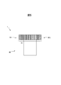
- FIG. 8 is a view showing an absorbent article 1 according to the second embodiment.
- the configuration of the side flaps SF1 and SF2 (or the configuration of the side flap forming member 10) is the absorption shown in FIG. 1 (first embodiment).
- This is different from the property article 1.
- the first web 7a of the side flap SF1 and the first web 7a of the side flap SF2 are configured by a common web.
- the first web 7a of the side flap SF1 and the first web 7a of the side flap SF2 are configured by two separate webs. The usage amount of the first web 7a can be reduced, and the cost can be reduced.
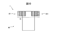
- FIG. 9 and 10 are views for explaining a method for manufacturing the absorbent article 1 according to the second embodiment.
- 9A, 9B, and 10 correspond to FIGS. 3A, 3B, and 5.
- FIG. 8 the continuous sheet-like material web W ⁇ b> 0 is supplied to the cutting device 51 as shown in FIG.
- the cutter roll of the cutting device 51 has a third cutting blade extending along the rotation direction on the outer peripheral surface at a position intermediate between the two cutting blades in the rotation axis direction.
- the material web W0 is cut by the cutting device 51, and as shown in FIG.
- the central web WM0 is further divided into two equal parts by the cutting device 51 to form the central webs WM01 and WM02.
- the outer edge in the transverse direction of the central web WM01 is Q1 (first edge)
- the outer edge in the transverse direction of the central web WM02 is Q2 (second edge).
- Other manufacturing steps are the same as those shown in FIGS. 3C, 3D, and 4A to 4D, and the absorbent article 1 having the configuration shown in FIG. 10 (FIG. 8) is finally completed.
- the absorbent article of the present invention is not limited to the above-described embodiments, and can be appropriately combined and changed without departing from the object and spirit of the present invention.
Abstract
吸収性物品(1)は、吸収性本体(AB)と、吸収性本体の幅方向の両端部から外側に延出する一対のサイドフラップ(SF1、SF2)と、を備え、サイドフラップは、不織布(7a)と、不織布に積層されたエラストマー部材(12)と、を含む。その製造方法は、第1のギア延伸処理が事前に施された不織布用の資材不織布を、記エラストマー部材に、伸長可能に部分的に接合して、積層体を形成する形成工程と、積層体に、第2のギア延伸処理を施す延伸工程であって、第2のギア延伸処理で資材不織布が延伸される方向と、第1のギア延伸処理で資材不織布が延伸された方向とは所定角度範囲内で同一の延伸方向である、延伸工程と、を備える。
Description
本発明は吸収性物品の製造方法に関する。
使い捨ておむつのような吸収性物品が知られている。その吸収性物品は、例えば吸収性本体と、吸収性本体の幅方向の両端部から外側に延出する一対のサイドフラップと、を備えている。そのようなサイドフラップの製造方法として、特許文献1(特表平11-506037号公報)に、使い捨ておむつのサイドパネル(サイドフラップ)の製造方法が開示されている。この製造方法では、サイドフラップ用の資材であるラミネート部材に延伸処理を施して、幅方向に伸縮性を有するサイドパネルを製造している。ラミネート部材としては、シート(不織布)とエラストマー部材とが積層された部材が挙げられる。
特許文献1では、サイドフラップに伸縮性を十分に付与するために、ラミネート部材、すなわち不織布とエラストマー部材とが互いに密着されて積層された部材に延伸処理を施している。このとき、エラストマー部材はある程度の伸長性を有しているので、上記の延伸処理に追随して伸長可能である。しかし、不織布はほとんど伸長性を有していないため、上記の延伸処理にあまり追随できず、エラストマー部材ほどには伸長できない。加えて、エラストマー部材と不織布とで延伸処理による伸長の仕方(概ね均等に伸長するか、各部分で伸長の程度が異なるか、など)も相違する。これらの結果、上記の延伸処理の程度等によっては、エラストマー部材の伸長に不織布が追随できず、不織布が弱化したり、部分的に切断されたりするおそれがある。仮にそのような不織布及びエラストマー部材を用いたサイドフラップが吸収性物品に適用されると、吸収性物品の使用時にサイドフラップが大きく伸長されたとき、サイドフラップが切断したり、サイドフラップに伸び止まり感がなくなって使用し難くなったりするおそれがある。したがって、そのようなサイドフラップは吸収性物品に適用できず、製造不良になってしまう。
本発明の目的は、サイドフラップを有する吸収性物品の製造方法において、エラストマー部材と不織布とが積層されたサイドフラップを形成するとき、不織布の弱化や切断を抑制し、伸びに優れたサイドフラップを形成することが可能な吸収性物品の製造方法を提供することにある。
本発明の吸収性物品の製造方法は次のとおりである。(1)吸収性本体と、前記吸収性本体の幅方向の両端部から外側に延出する一対のサイドフラップと、を備え、前記一対のサイドフラップの各々は、不織布と、前記不織布に積層されたエラストマー部材と、を含む吸収性物品の製造方法であって、第1のギア延伸処理が事前に施された前記不織布用の資材不織布を、前記エラストマー部材に、伸長可能に部分的に接合して、積層体を形成する形成工程と、前記積層体に、第2のギア延伸処理を施す延伸工程であって、前記第2のギア延伸処理で前記資材不織布が延伸される方向と、前記第1のギア延伸処理で前記資材不織布が延伸された方向とは所定角度範囲内で同一の延伸方向である、延伸工程と、を備える、吸収性物品の製造方法。
本吸収性物品の製造方法では、第1のギア延伸処理を事前に施された資材不織布を、エラストマー部材に伸長可能に部分的に接合する。すなわち、事前に繊維をほぐされ、伸長性を付与された資材不織布を、エラストマー部材に対して伸長可能となるように(全面的ではなく)部分的に接合している。そのため、第2のギア延伸処理が施されるとき、資材不織布は、いきなりエラストマー部材と共に延伸される場合と比較して、極めて容易に伸長できる。それと共に、資材不織布は、エラストマー部材と伸長の仕方が多少異なっても、エラストマー部材の伸長に部分的に追随するが完全には追随しないで、自身の特性に応じて伸長できる。これらの相乗効果により、積層体を全体として適切に延伸できる。すなわち、第2のギア延伸工程において、サイドフラップに伸縮性を付与すべく十分な延伸処理を施しても、資材不織布は延伸処理に追随でき、弱化や切断をすることなく伸長できる。それにより、サイドフラップを形成するとき、不織布の弱化や切断を抑制でき、伸びに優れたサイドフラップを形成できる。
本発明の吸収性物品の製造方法は、(2)前記一対のサイドフラップの各々は、前記エラストマー部材に、前記不織布とは反対の側から積層された他の不織布を更に含み、前記形成工程は、第3のギア延伸処理が事前に施された前記他の不織布用の他の資材不織布を、前記エラストマー部材における前記資材不織布と接合する側とは反対の側に、伸長可能に部分的に接合する工程を含む、上記(1)に記載の吸収性物品の製造方法、であってもよい。
本吸収性物品の製造方法では、エラストマー部材に更に他の資材不織布を接合するとき、第3のギア延伸処理を事前に施された他の資材不織布を、エラストマー部材に伸縮可能に部分的に接合する。それにより、第2のギア延伸処理を施されるとき、他の資材不織布は、いきなりエラストマー部材と共に延伸される場合と比較して、極めて容易に伸長できると共に、エラストマー部材の伸長に部分的に追随するが完全には追随しないで、自身の特性に応じて伸長できる。それらにより、第2のギア延伸工程において、他の資材不織布は弱化や切断をすることなく伸長でき、それにより積層体全体としては適切に延伸できる。また、他の資材不織布が追加されるので、形成工程における積層体全体の強度を向上できる。それにより、サイドフラップを形成するとき、不織布の弱化や切断を抑制できる。
本吸収性物品の製造方法では、エラストマー部材に更に他の資材不織布を接合するとき、第3のギア延伸処理を事前に施された他の資材不織布を、エラストマー部材に伸縮可能に部分的に接合する。それにより、第2のギア延伸処理を施されるとき、他の資材不織布は、いきなりエラストマー部材と共に延伸される場合と比較して、極めて容易に伸長できると共に、エラストマー部材の伸長に部分的に追随するが完全には追随しないで、自身の特性に応じて伸長できる。それらにより、第2のギア延伸工程において、他の資材不織布は弱化や切断をすることなく伸長でき、それにより積層体全体としては適切に延伸できる。また、他の資材不織布が追加されるので、形成工程における積層体全体の強度を向上できる。それにより、サイドフラップを形成するとき、不織布の弱化や切断を抑制できる。
本発明の吸収性物品の製造方法は、(3)前記形成工程において、前記資材不織布と前記エラストマー部材とは、前記エラストマー部材の前記延伸方向の両端縁が前記資材不織布の前記延伸方向の両端縁の内側に存在するように接合される、上記(1)又は(2)に記載の吸収性物品の製造方法、であってもよい。
本吸収性物品の製造方法では、エラストマー部材が資材不織布の全面には存在せず、よって資材不織布のみの部分が存在する。そのため、エラストマー部材と資材不織布とが重なっている部分と比較して、資材不織布のみの部分では、厚さが小さくなる。その結果、延伸工程において、エラストマー部材と資材不織布とが重なっている部分と比較して、資材不織布のみの部分に生じる歪は小さくなるので、当該部分はより弱化され難く、より切断され難くなる。それにより、サイドフラップを、特に延伸方向と直交する搬送方向の伸びに対して、より弱化され難く、より切断され難くすることができる。すなわち、サイドフラップを形成するとき、不織布の弱化や切断を抑制することができる。
本吸収性物品の製造方法では、エラストマー部材が資材不織布の全面には存在せず、よって資材不織布のみの部分が存在する。そのため、エラストマー部材と資材不織布とが重なっている部分と比較して、資材不織布のみの部分では、厚さが小さくなる。その結果、延伸工程において、エラストマー部材と資材不織布とが重なっている部分と比較して、資材不織布のみの部分に生じる歪は小さくなるので、当該部分はより弱化され難く、より切断され難くなる。それにより、サイドフラップを、特に延伸方向と直交する搬送方向の伸びに対して、より弱化され難く、より切断され難くすることができる。すなわち、サイドフラップを形成するとき、不織布の弱化や切断を抑制することができる。
本発明の吸収性物品の製造方法は、(4)前記形成工程において、前記資材不織布と前記エラストマー部材とは、前記エラストマー部材の前記延伸方向と直交する搬送方向の両端部が前記資材不織布における前記搬送方向の両端部の内側に存在するように接合される、上記(1)乃至(3)のいずれか一項に記載の吸収性物品の製造方法、であってもよい。
本吸収性物品の製造方法では、エラストマー部材が資材不織布の全面には存在せず、よって資材不織布のみの部分が存在する。そのため、エラストマー部材と資材不織布とが重なっている部分と比較して、資材不織布のみの部分では、厚さが小さくなる。その結果、延伸工程において、エラストマー部材と不織布とが重なっている部分と比較して、資材不織布のみの部分に生じる歪は小さくなるので、当該部分はより弱化され難く、より切断され難くなる。それにより、サイドフラップを、特に延伸方向の伸びに対して、より弱化され難く、より切断され難くすることができる。それにより、サイドフラップを形成するとき、不織布の弱化や切断を抑制することができる。
本吸収性物品の製造方法では、エラストマー部材が資材不織布の全面には存在せず、よって資材不織布のみの部分が存在する。そのため、エラストマー部材と資材不織布とが重なっている部分と比較して、資材不織布のみの部分では、厚さが小さくなる。その結果、延伸工程において、エラストマー部材と不織布とが重なっている部分と比較して、資材不織布のみの部分に生じる歪は小さくなるので、当該部分はより弱化され難く、より切断され難くなる。それにより、サイドフラップを、特に延伸方向の伸びに対して、より弱化され難く、より切断され難くすることができる。それにより、サイドフラップを形成するとき、不織布の弱化や切断を抑制することができる。
本発明の吸収性物品の製造方法は、(5)前記形成工程において、前記資材不織布を前記エラストマー部材に接合するときは、溶着で接合する、上記(1)乃至(4)のいずれか一項に記載の吸収性物品の製造方法、であってもよい。
本吸収性物品の製造方法では、エラストマー部材と資材不織布とが溶着(例示:熱溶着、超音波溶着)により接合され、接着剤により接合されていない。それにより、延伸加工において接着剤が染み出し、延伸加工用の機器に付着し、後続のエラストマー部材及び資材不織布に付着して、伸縮性を阻害する、という事態を回避できる。それにより、サイドフラップに伸縮性を付与すべく十分な延伸処理を施しても、資材不織布は、その延伸処理の程度に追随できるので、サイドフラップを形成するとき、不織布の弱化や切断を抑制することができる。
本吸収性物品の製造方法では、エラストマー部材と資材不織布とが溶着(例示:熱溶着、超音波溶着)により接合され、接着剤により接合されていない。それにより、延伸加工において接着剤が染み出し、延伸加工用の機器に付着し、後続のエラストマー部材及び資材不織布に付着して、伸縮性を阻害する、という事態を回避できる。それにより、サイドフラップに伸縮性を付与すべく十分な延伸処理を施しても、資材不織布は、その延伸処理の程度に追随できるので、サイドフラップを形成するとき、不織布の弱化や切断を抑制することができる。
本発明の吸収性物品の製造方法は、(6)前記形成工程において、前記資材不織布を前記エラストマー部材に接合するときは、接着剤で接合する、上記(1)乃至(4)のいずれか一項に記載の吸収性物品の製造方法、であってもよい。
本吸収性物品の製造方法では、エラストマー部材と資材不織布とが接着剤(例示:ホットメルト接着剤)により接合されているので、延伸加工においてエラストマー部材と資材不織布の延伸に追随して接着剤も延伸できる。そのため、資材不織布において接着箇所で繊維同士が互いに固定されてしまい、資材不織布の延伸に偏りが生じて、資材不織布が弱化したり、部分的に切断したりする、という事態を回避できる。それにより、サイドフラップに伸縮性を付与すべく十分な延伸処理を施しても、資材不織布は、その延伸処理の程度に追随できるので、サイドフラップを形成するとき、不織布の弱化や切断を抑制することができる。
本吸収性物品の製造方法では、エラストマー部材と資材不織布とが接着剤(例示:ホットメルト接着剤)により接合されているので、延伸加工においてエラストマー部材と資材不織布の延伸に追随して接着剤も延伸できる。そのため、資材不織布において接着箇所で繊維同士が互いに固定されてしまい、資材不織布の延伸に偏りが生じて、資材不織布が弱化したり、部分的に切断したりする、という事態を回避できる。それにより、サイドフラップに伸縮性を付与すべく十分な延伸処理を施しても、資材不織布は、その延伸処理の程度に追随できるので、サイドフラップを形成するとき、不織布の弱化や切断を抑制することができる。
本発明の吸収性物品の製造方法は、(7)前記形成工程の前に、前記資材不織布に、前記第1のギア延伸処理を事前に施す事前延伸工程を更に備え、前記事前延伸工程において、前記資材不織布は一対の延伸ロールへ搬送され、前記一対の延伸ロールにより前記第1のギア延伸処理を施され、前記資材不織布の前記第1のギア延伸処理への送り込み速度は、前記一対の延伸ロールの周速度よりも速い、上記(1)乃至(6)のいずれか一項に記載の吸収性物品の製造方法、であってもよい。
資材不織布を延伸処理する場合、資材不織布に生じる歪は、ギア延伸処理の前に資材不織布が有する歪みと、一対の延伸ロールに資材不織布が噛み込まれるときに生じる歪みとの合計になる。ここで、資材不織布が耐えられる歪みには上限があり、資材不織布の弱化や切断を抑えるためには、その歪みを小さくすることが望ましい。そこで本吸収性物品の製造方法では、資材不織布の送り込み速度を一対の延伸ロールの周速度よりも速くすることで(オーバーフィード)、ギア延伸処理の前に資材不織布が有する歪みを小さくしている。その結果、資材不織布に生じる歪みの量を小さくでき、ギア延伸処理による歪みの影響を抑えることができる。それにより、サイドフラップを形成するとき、不織布の弱化や切断を抑制することができる。
資材不織布を延伸処理する場合、資材不織布に生じる歪は、ギア延伸処理の前に資材不織布が有する歪みと、一対の延伸ロールに資材不織布が噛み込まれるときに生じる歪みとの合計になる。ここで、資材不織布が耐えられる歪みには上限があり、資材不織布の弱化や切断を抑えるためには、その歪みを小さくすることが望ましい。そこで本吸収性物品の製造方法では、資材不織布の送り込み速度を一対の延伸ロールの周速度よりも速くすることで(オーバーフィード)、ギア延伸処理の前に資材不織布が有する歪みを小さくしている。その結果、資材不織布に生じる歪みの量を小さくでき、ギア延伸処理による歪みの影響を抑えることができる。それにより、サイドフラップを形成するとき、不織布の弱化や切断を抑制することができる。
本発明の吸収性物品の製造方法は、(8)前記第1のギア延伸処理の延伸倍率は、前記第2のギア延伸処理の延伸倍率よりも小さい、上記(1)乃至(7)のいずれか一項に記載の吸収性物品の製造方法、であってもよい。
本吸収性物品の製造方法では、第1のギア延伸処理の延伸倍率が、第2のギア延伸処理の延伸倍率よりも小さくなっている。それにより、資材不織布に第1のギア延伸処理を施す際に、不必要に延伸し過ぎて、事前に資材不織布が弱化したり、切断したりする事態を回避できる。その結果、資材不織布に適切な伸長性を付与し、適切に繊維をほぐすことができる。それにより、サイドフラップを形成するとき、不織布の弱化や切断を抑制することができる。
本吸収性物品の製造方法では、第1のギア延伸処理の延伸倍率が、第2のギア延伸処理の延伸倍率よりも小さくなっている。それにより、資材不織布に第1のギア延伸処理を施す際に、不必要に延伸し過ぎて、事前に資材不織布が弱化したり、切断したりする事態を回避できる。その結果、資材不織布に適切な伸長性を付与し、適切に繊維をほぐすことができる。それにより、サイドフラップを形成するとき、不織布の弱化や切断を抑制することができる。
本発明により、サイドフラップを有する吸収性物品の製造方法において、エラストマー部材と不織布とが積層されたサイドフラップを形成するとき、不織布の弱化や切断を抑制し、伸びに優れたサイドフラップを形成することが可能な吸収性物品の製造方法を提供することが可能となる。
(第1の実施の形態)
本実施の形態に係る吸収性物品について、テープ型(オープンタイプ)の使い捨ておむつを例に説明する。ただし本発明の吸収性物品の種類及び用途はその例に限定されるものではなく、本発明の範囲を逸脱しない範囲で他の吸収性物品に対しても適用可能である。
本実施の形態に係る吸収性物品について、テープ型(オープンタイプ)の使い捨ておむつを例に説明する。ただし本発明の吸収性物品の種類及び用途はその例に限定されるものではなく、本発明の範囲を逸脱しない範囲で他の吸収性物品に対しても適用可能である。
図1は吸収性物品1(使い捨ておむつ)を示す図であり、吸収性物品1を展開して拡げた状態での平面図を示す。吸収性物品1は、互いに直交する長手方向Lと、幅方向Wと、厚さ方向Tを有し、幅方向Wの中心を通り長手方向Lに延びる中央軸線CLと、長手方向Lの中心を通り幅方向Wに延びる中央軸線CWを有する。本明細書では、展開して平坦に拡げた吸収性物品1を上面側又は下面側から厚さ方向に見ることを「平面視」という。「肌側」及び「非肌側」とは吸収性物品1の着用時に、吸収性物品1の厚さ方向において相対的に着用者の肌面に近い側及び肌面から遠い側をそれぞれ意味する。中央軸線CLに向かう方向及び遠ざかる方向を、それぞれ幅方向Wの内側の方向及び外側の方向とする。中央軸線CWに向かう方向及び遠ざかる方向を、それぞれ長手方向Lの内側の方向及び外側の方向とする。これらの定義は、吸収性物品1を構成する資材や部材にも共通に適用される。なお、図1は吸収性物品1を非肌面側から見た図である。
吸収性物品1は、長手方向Lにおいて、着用者の背側の胴回りに対応する背側胴回り領域S1と、着用者の腹側の胴回りに対応する腹側胴回り領域S2と、着用者の股間に対応し、背側胴回り領域S1と腹胴回り領域S2との間に位置する股領域S3とを有する。吸収性物品1は、背側胴回り領域S1から腹側胴回り領域S2まで長手方向Lに延びる吸収性本体ABと、背側胴回り領域S1において吸収性本体ABの幅方向Wの両端部から外側に延出する一対のサイドフラップSF1、SF2と、一対のサイドフラップSF1、SF2の幅方向Wの外側の端部から外側に延出する一対の係合テープ8、8と、を備える。吸収性物品1は、例えば背側胴回り領域S1の一対のサイドフラップSF1、SF2の一対の係合テープ8、8が腹側胴回り領域S2の吸収性本体ABの幅方向W中央の係合対象部材14と係合されることでおむつとして装着される。股領域S3は幅方向Wにくびれていてもよい。長手方向Lにおける背側胴回り領域S1に向かう方向及び腹側胴回り領域S2に向かう方向をそれぞれ後側方向及び前側方向ともいう。
吸収性物品1は、表面シート2と裏面シート3と吸収体4とを備える。表面シート2は、着用者の肌側に位置する液透過性のシートである。表面シート2としては、例えば液透過性の不織布や織布、液透過孔が形成された合成樹脂フィルム、これらの複合シートなど、任意の液透過性シートが挙げられる。裏面シート3は、着用者の非肌側に位置する液不透過性のシートである。裏面シート3としては、例えば液不透過性の不織布や合成樹脂フィルム、これらの複合シート、SMS不織布など、任意の液不透過性シートが挙げられる。吸収体4は、表面シート2及び裏面シート3との間に位置する液吸収性及び液保持性の材料である。吸収体4としては、パルプ繊維、合成繊維、吸収性ポリマなどが挙げられる。吸収体4と表面シート2及び裏面シート3とはそれぞれ接着剤により接合され、表面シート2と裏面シート3とはそれらの周縁部分において接着剤により接合される。表面シート2、吸収体4及び裏面シート3の間の接合用の接着剤は、吸収性物品1で一般的に使用される公知の材料、例えば熱可塑性接着剤を使用できる。
吸収性物品1は、さらに一対の防漏壁5、5と脚部伸縮部材6、6と外装シート9とを備える。一対の防漏壁5、5は、表面シート2における幅方向Wの両側の表面を覆うように長手方向Lに沿って延び、幅方向Wに離間して配置される一対の側部シートである。一対の防漏壁5、5は、それぞれ、表面シート2の幅方向Wの両側の表面において、幅方向Wの外側の端部が固定されて固定端とされ、幅方向Wの内側の端部が伸縮可能なギャザーを形成するように自由端とされる。一対の防漏壁5、5の自由端の近傍には、それぞれ長手方向Lに沿って延びるゴムのような線状の弾性体5aが例えば2本ずつ配置される。脚部伸縮部材6は、着用者の大腿部に当接する股領域S3の幅方向Wの両側をそれぞれ長手方向Lに伸縮させるゴムのような線状の弾性体である。外装シート9は、裏面シート3の非肌側に配置され、裏面シート3を補強し、その手触りを改善する。裏面シート3の非肌側に接合された状態で、一対の防漏壁5、5とその周縁部分において相互に接続される。防漏壁5、外装シート9の材料に特に制限はなく、例えば防漏壁5としては表面シート2の材料、外装シート9としては裏面シート3の材料が挙げられる。
吸収性物品1は、背側胴回り領域S1に、伸縮部材11を更に備える。伸縮部材11は、幅方向Wに伸縮性を有するエラストマーのようなシート状の部材であり、一対のサイドフラップSF1、SF2の幅方向Wの間に配置され、例えばウェストギャザーとして機能する。伸縮部材11は、背側胴回り領域S1の表面シート2と裏面シート3との間、表面シート2の肌側の表面及び裏面シート3の非肌側の表面のいずれかの位置に、接着剤で取り付けられる。伸縮部材11は平面視で吸収体4と部分的に重なる、又は重ならないように配置される。本実施の形態では、伸縮部材11は、表面シート2と裏面シート3との間に、伸縮部材11における長手方向Lの内側の部分が吸収体4と厚み方向に重なるように配置される。それにより吸収性物品1の着用時に胴回り領域のフィット性を向上できる。
吸収性本体ABの幅方向Wの両端部から外側に延出する一対のサイドフラップSF1、SF2の各々は、第1のウェブ7aと、第1のウェブ7aと厚み方向Tに重なる第2のウェブ7bとを含む。すなわち各サイドフラップSFは2層のウェブで形成され、2プライ構造を有する。各ウェブの材料としては特に制限されるものでなく公知の材料を使用できるが、例えば不織布が挙げられる。ただし、本実施の形態では、サイドフラップSF1の第1のウェブ7aとサイドフラップSF2の第1のウェブ7aとは共通の一枚のウェブで構成されている。そして、サイドフラップSF1の第2のウェブ7bは第1のウェブ7aの一方の端部に、サイドフラップSF2の第2のウェブ7bは第1のウェブ7aの他方の端部にそれぞれ重ねられ、接合される。したがって、本実施の形態では、一枚の第1のウェブ7aとその幅方向Wの両端部に積層された二枚の第2のウェブ7bとでサイドフラップ形成部材10が形成される。そして、サイドフラップ形成部材10が吸収性本体ABにおける背側胴回り領域S1の外装シート9の非肌側に接着剤等で接合されることで、吸収性本体ABから外側に延出する一対のサイドフラップSF1、SF2が形成される。このとき、第2のウェブ7bが例えば吸収性物品1の非肌側に位置するようにサイドフラップ形成部材10が配置される。ただし、第2のウェブ7bが吸収性物品1の肌側でもよい。
本実施の形態では、サイドフラップSF1では、例えば第1のウェブ7aの幅方向Wの外側の端縁7e1を基準として、第2のウェブ7bの幅方向Wの外側の端縁7e3が当該基準から幅方向Wの内側の所定距離に位置するように、第1のウェブ7aと第2のウェブ7bとが接合される。同様に、サイドフラップSF2では、第1のウェブ7aの幅方向Wの外側の端縁7e2を基準として、第2のウェブ7bの幅方向Wの外側の端縁7e4が当該基準から幅方向Wの内側の所定距離に位置するように、第1のウェブ7aと第2のウェブ7bとが接合される。本実施の形態では特に所定距離をゼロ(0)としている。すなわち、サイドフラップSF1では第1のウェブ7aの端縁7e1に、第2のウェブ7bの端縁7e3が重なるように、第1のウェブ7aと第2のウェブ7bとが接合される。同様に、サイドフラップSF2では第1のウェブ7aの端縁7e2に、第2のウェブ7bの端縁7e4が重なるように、第1のウェブ7aと第2のウェブ7bとが接合される。本実施の形態では、更に第1のウェブ7aの長手方向Lの寸法と、第2のウェブ7bの長手方向Lの寸法とは同じである。
各サイドフラップSFは、更にエラストマー部材12を含む。エラストマー部材12は、幅方向Wに伸縮性を有するシート状の部材であり、第1のウェブ7aと第2のウェブ7bとの間に積層される。エラストマー部材12の材料としては、公知のエラストマー材料、例えば天然ゴム、合成ゴム、ゴムフォームなどのエラストマー樹脂が挙げられる。
本実施の形態では、サイドフラップSF1にて、第1のウェブ7aの端縁7e1を基準として、エラストマー部材12の幅方向Wの外側の端縁12e1が当該基準から幅方向Wの内側の所定距離に位置するように、第1のウェブ7aとエラストマー部材12とが接合される。同様に、サイドフラップSF2にて、第1のウェブ7aの端縁7e2を基準として、エラストマー部材12の幅方向Wの外側の端縁12e2が当該基準から幅方向Wの内側の所定距離に位置するように、第1のウェブ7aとエラストマー部材12とが接合される。また、各サイドフラップSFでは、長手方向Lにおいて、第1のウェブ7aの両端縁の内側に、エラストマー部材12の両端縁が位置するように、第1のウェブ7aとエラストマー部材12とが接合される。また、各サイドフラップSFでは、エラストマー部材12における幅方向Wの内側の一部が、各サイドフラップSFにおける吸収性本体ABとの取り付け位置に重なるように、エラストマー部材12が第1のウェブ7aに配置される。言い換えると、エラストマー部材12における幅方向Wの内側の一部が、吸収性本体ABの端縁ABeよりも幅方向Wの内側になるように、エラストマー部材12が第1のウェブ7aに配置される。
第1のウェブ7aはギア延伸処理を事前に施されてからエラストマー部材12に接合される。したがって第1のウェブ7aは単独でも幅方向Wに伸縮性を有する。第1のウェブ7aとエラストマー部材12とは、接着剤や熱溶着などで接合されるが、全面的に接合されるのではなく、部分的に接合される。部分的な接合については後述される。この場合、第1のウェブ7aとエラストマー部材12とがサイドフラップSFとして伸長されるとき、第1のウェブ7aは、エラストマー部材12の伸長に対して部分的に追随するが完全には追随しないで、自身の特性に応じて伸長できるので、弱化や切断の発生を抑制できる。同様に、第2のウェブ7bもギア延伸処理を事前に施されてからエラストマー部材12に部分的に接合される。したがって、第1のウェブ7aと同様の上記の作用効果を奏する。
各サイドフラップSFにおける第1のウェブ7aとエラストマー部材12と第2のウェブ7bとが積層された領域には、各サイドフラップSFを長手方向Lに横断するようにギア延伸処理を施された延伸領域13が形成される。各サイドフラップSFは、延伸領域13の作用により、幅方向Wの外側に伸縮可能に形成される。この場合、第1のウェブ7aとエラストマー部材12と第2のウェブ7bとが一体で伸長されるとき、第1のウェブ7a及び第2のウェブ7bはエラストマー部材12の伸長に対して部分的に追随するが完全には追随しないで自身の特性に応じて伸長できるので、弱化や切断の発生を抑制できる。
なお、サイドフラップSFとしては、第1のウェブ7a及び第2のウェブ7bのうちのいずれか一枚を用いていればよく、他の一枚を省略してもよい。
サイドフラップSF1、SF2の幅方向Wの外側の端部から延出する係合テープ8、8の各々は、厚さ方向Tで第1のウェブ7aと第2のウェブ7bとの間、第1のウェブ7aの肌側、又は第2のウェブ7bの非肌側のいずれかの位置に、例えば接着剤で接合される。本実施の形態では、第1のウェブ7aと第2のウェブ7bとの間で、エラストマー部材12よりも非肌側に配置される。係合テープ8としては面ファスナーや粘着テープが挙げられる。サイドフラップSF1では、第1のウェブ7aの幅方向Wの外側の端縁7e1を基準として、係合テープ8の幅方向Wの外側の端縁8e1が当該基準から幅方向Wの外側に予め設定された寸法で延出するように、第1のウェブ7aと係合テープ8とが接合されている。同様に、サイドフラップSF2では、第1のウェブ7aの幅方向Wの外側の端縁7e2を基準として、係合テープ8の幅方向Wの外側の端縁8e2が当該基準から幅方向Wの外側に予め設定された寸法で延出するように、第1のウェブ7aと係合テープ8とが接合されている。
吸収性物品1は、更に、腹側胴回り領域S2に、係合対象部材14を備えている。係合対象部材14は、係合テープ8、8を連結される対象となるシートであり、例えば係合テープ8、8が面ファスナーのフックの場合には係合対象部材14は面ファスナーのループであり、係合テープ8、8が粘着テープの場合には係合対象部材14は粘着テープが粘着可能なシートである。係合対象部材14は、例えば、腹側胴回り領域S2の外装シート9の非肌側の表面の位置に、接着剤で取り付けられている。吸収性物品1は、さらに、腹側胴回り領域S2において吸収性本体ABの幅方向Wの両端部から外側に延出する一対の腹側サイドフラップ(図示されず)を備えていてもよい。一対の腹側サイドフラップは、着用時に腹側胴回り領域S2を背側胴回り領域S1に連結するためのシートである。
次に、本実施の形態に係る吸収性物品の製造装置について説明する。図2は、吸収性物品1の製造装置50の構成の一例を示す。製造装置50は、切り分けユニット50a、側部ウェブギア延伸ユニット50b、中央ウェブギア延伸ユニット50c、エラストマー部材配置ユニット50d、係合テープ接合ユニット50e、折り畳みユニット50f、半製品ギア延伸ユニット50g、及び、吸収性本体形成ユニット50hを備える。
製造装置50は、吸収性物品1やそれを構成する資材などの搬送に関し、搬送方向MD、搬送方向MDに直交し搬送面に沿う横断方向CD及び搬送方向MDと横断方向CDとに直交する上下方向TDを有する。ただし、吸収性物品1やそれを構成する資材の長手方向、幅方向及び厚さ方向はいずれも搬送方向MD、横断方向CD及び上下方向TDと同じである。したがって吸収性物品1やそれを構成する資材においても、長手方向、幅方向及び厚さ方向についてそれぞれ搬送方向MD、横断方向CD及び上下方向TDを用いる。
切り分けユニット50aはロールWR1と切断装置51を備える。切断装置51は、対面配置されたカッターロールとアンビルロールを含む。カッターロールは、外周面上に、回転方向に沿って延び、回転軸方向に所定寸法の間隔で配置された二つの切断刃を有する。切断装置51は、ロールWR1から供給される資材ウェブW0をカッターロールとアンビルロールとの間に挟んで切断し、中央ウェブWM0と、第1、第2の側部ウェブWE10、WE20とを形成する。
中央ウェブギア延伸ユニット50cは入口ニップロール58とギア延伸装置59と出口ニップロール60とを備える。入口ニップロール58及び出口ニップロール60は中央ウェブWM0、WM1のテンションを調整する。ギア延伸装置59は対面配置された一対の延伸ロールを含む。一対の延伸ロールはそれぞれ外周面上に、回転方向に沿って延び、回転軸方向に交互に並ぶ複数の凸部と凹部(歯部と溝部)を有する。ギア延伸装置59は、中央ウェブWM0を一対の延伸ロールの互いに噛み合う凸部と凹部との間に挟んでギア延伸し、横断方向に伸縮可能な中央ウェブWM1を形成する。
エラストマー部材配置ユニット50dは切断装置62と塗布装置63と切断装置64とを備える。切断装置62は、ロールWR2から供給されるエラストマー部材ウェブWL0を、対面配置されたカッターロールとアンビルロールとの間に挟んで横断方向の中央を切断し、一対のエラストマー部材ウェブWL1、WL2を形成する。塗布装置63は、それら一対のエラストマー部材ウェブWL1、WL2の各々の一方の面に非全面(部分的)に接着剤を塗布する。切断装置64は、対面配置されたカッターロール及びアンビルロール並びにアンビルロールに対面配置された押圧ロールを含む。切断装置64は、カッターロールとアンビルロールとの間に供給された一対のエラストマー部材ウェブWL1、WL2を、アンビルロールの外周面に吸引しつつ、カッターロールの切断刃によって搬送方向に所定寸法ごとに切断して、一対のエラストマー部材112を形成する。そして、エラストマー部材112のうちの接着剤を塗布された面を中央ウェブWM1に押圧ロールで押し付け、貼り付けて、中央ウェブWM2を形成する。
係合テープ接合ユニット50eは切断装置66と塗布装置67と切断装置68とを備える。切断装置66は、ロールWR3から供給され係合テープウェブWT0を、対面配置されたカッターロールとアンビルロールとの間に挟んで横断方向の中央を切断し、一対の係合テープウェブWT1、WT2を形成する。塗布装置67は、一対の係合テープウェブWT1、WT2の各々の一方の面に非全面(部分的)に接着剤を塗布する。切断装置68は、対面配置されたカッターロール及びアンビルロール並びにアンビルロールに対面配置された押圧ロールを含む。切断装置68は、カッターロールとアンビルロールとの間に供給された一対の係合テープウェブWT1、WT2を、アンビルロールの外周面に吸引しつつ、カッターロールの切断刃で搬送方向に所定寸法ごとに切断して、一対の係合テープ108を形成する。そして、係合テープ108のうちの接着剤を塗布された面を中央ウェブWM2に押圧ロールで押し付け、貼り付けて、中央ウェブWM3を形成する。
折り畳みユニット50fは、セーラーのような折り畳み治具を含む折り畳み装置70を備えている。折り畳み装置70は、中央ウェブWM3の横断方向の両外側に延出する一対の係合テープ8、8の延出部分を内側に向かって、中央ウェブWM3の横断方向の両端縁の位置で折り畳む。この場合、中央ウェブWM3におけるエラストマー部材112の有る面とは反対側の面に被さるように折り畳む。それにより中央ウェブWM4が形成される。
側部ウェブギア延伸ユニット50bは入口ニップロール52とギア延伸装置53と出口ニップロール54と塗布装置55と押圧ロール56とを備える。入口ニップロール52及び出口ニップロール54は第1、第2の側部ウェブWE10、WE11、WE20、WE21のテンションを調整する。ギア延伸装置53は対面配置された一対の延伸ロールを含む。一対の延伸ロールはそれぞれその外周面上に、回転方向に沿って延び、回転軸方向に交互に並んだ複数の凸部と凹部(歯部と溝部)を有する。ギア延伸装置53は、第1、第2の側部ウェブWE10、WE20を一対の延伸ロールの互いに噛み合う凸部と凹部との間に挟んでギア延伸して、横断方向に伸縮可能な第1、第2の側部ウェブWE11、WE21を形成する。塗布装置55は第1、第2の側部ウェブWE11、WE21の一方の面に非全面(部分的)に接着剤を塗布する。押圧ロール56は、第1、第2の側部ウェブWE11、WE21の各々の接着剤を塗布された面を中央ウェブWM4に押し付け、貼り付ける。それにより半製品ウェブWP1が形成される。
半製品ギア延伸ユニット50gは入口ニップロール72とギア延伸装置73と出口ニップロール74と切断装置75とを備える。入口ニップロール72及び出口ニップロール74は半製品ウェブWP1、WP2のテンションを調整する。ギア延伸装置73は対面配置された一対の延伸ロールを含む。一対の延伸ロールはそれぞれ外周面上に、回転方向に沿って延び、回転軸方向に交互に並んだ複数の凸部と凹部(歯部と溝部)を有する。ギア延伸装置73は、半製品ウェブWP1を一対の延伸ロールの凸部と凹部(又は歯部と溝部)との間に挟んでギア延伸する。切断装置75は、互いに対面配置されたカッターロール及びアンビルロールを備える。切断装置75は、延伸された半製品ウェブWP1をカッターロールの切断刃によって搬送方向に所定寸法ごとに切断して、半製品ウェブWP2、すなわち個々に分離されたサイドフラップ形成部材10を形成する。
吸収性本体形成ユニット50hは、吸収性本体ABを形成する。吸収性本体ABの形成方法としては従来知られた公知の方法を用いることができる。そして、半製品ウェブWP2、すなわち個々に分離されたサイドフラップ形成部材10を、吸収性本体ABの背側胴回り領域S1に接合して、吸収性物品1を製造する。
次に、本実施の形態に係る吸収性物品の製造方法につき図2~図6を参照して説明する。図3~図5は吸収性物品の製造方法を説明するためのウェブや半製品の構成例を模式的に示す。図6は、ギア延伸処理を説明するためのウェブの状態を模式的に示す。図3~図4は各ウェブや半製品が搬送方向MDに沿って図の上から下へ搬送されることを示し、搬送方向MDに連続的に延びる各ウェブや半製品の一部分を示す。なお搬送面(又は中央ウェブ)の横断方向の中心を通り搬送方向に延びる仮想的な中央軸線に向う方向及び遠ざかる方向を、横断方向の内側の方向及び外側の方向とする。本製造方法は、切り分け工程(切り分けユニット50a)、側部ウェブギア延伸工程(側部ウェブギア延伸ユニット50b)、中央ウェブギア延伸工程(中央ウェブギア延伸ユニット50c)、エラストマー部材配置工程(エラストマー部材配置ユニット50d)、係合テープ接合工程(係合テープ接合ユニット50e)、折り畳み工程(折り畳みユニット50f)、半製品ギア延伸工程(半製品ギア延伸ユニット50g)及び吸収性本体形成工程(吸収性本体形成ユニット50h)を備える。
切り分け工程では、図2に示すように、連続シート状の資材ウェブW0が切断装置51に供給される。資材ウェブW0は、第1のウェブ7a及び一対の第2のウェブ7b、7b用のウェブであり、図3(a)に示すように、第1のウェブ7a及び一対の第2のウェブ7b、7bとなる部分107を含む。資材ウェブW0は切断装置51により切り分けられて、図3(b)に示すように、中央ウェブWM0と、中央ウェブWM0における横断方向の一側及び他側それぞれに隣接する第1、第2の側部ウェブWE10、WE20とが形成される。中央ウェブWM0は、切断装置51のカッターロールの二つの切断刃間の所定寸法を、横断方向の寸法(幅)としており、第1のウェブ7aとなる部分107aを含む。第1、第2の側部ウェブWE10、WE20は、それぞれ第2のウェブ7bとなる部分107bを含む。その後、中央ウェブWM0は中央ウェブギア延伸工程へ供給され、第1、第2の側部ウェブWE10、WE20は側部ウェブギア延伸工程へ供給される。
ここで、ロールWR1から巻き戻された資材ウェブW0は横断方向の寸法にばらつきを有する。中央ウェブWM0は、横断方向に所定寸法の間隔で配置された二つの切断刃により資材ウェブW0から切り分けられるので、横断方向の寸法のばらつきをほとんど無くすことができ、すなわち横断方向の寸法を設計通りの寸法にできる。言い換えると、中央ウェブWM0の一方の端縁Q1及び他方の端縁Q2は、製造装置50の搬送面(図示されず)の適正な位置に存在しており、よって他のウェブを中央ウェブWM0上に配置するときの横断方向における基準とすることができる。中央ウェブWM1~WM4、半製品ウェブWP1、WP2の両端縁Q1、Q2についても同様である。
次いで、中央ウェブギア延伸工程(第1のギア延伸処理;事前延伸工程)では、図2に示すように、連続シート状の中央ウェブWM0がギア延伸装置59に供給される。そして、中央ウェブWM0はギア延伸装置59により横断方向のギア延伸処理を施されて、図3(c)に示すように、横断方向に伸長可能な中央ウェブWM1が形成される。中央ウェブWM1は、第1のウェブ7aとなる部分107aを含む。中央ウェブWM1は、エラストマー部材配置工程へ供給される。
ここで、ウェブへのギア延伸処理の状態について説明する。図6はウェブへのギア延伸処理の状態を模式的かつ部分的に示している。一対の延伸ロールが互いに噛み合う噛み合い領域80において、一方の延伸ロールの凸部(歯部)81aと、他方の延伸ロールの凸部(歯部)82aとの間に、ウェブ90(本工程では中央ウェブWM0)が噛み込まれている。ここで、対向する延伸ロールへ向かって凸部(歯部)81aがウェブ90を押し込むとき、ウェブ90が凸部(歯部)81aと当接する領域91では、ウェブ90の繊維が凸部(歯部)81aに押さえ付けられて移動できない状態になる。同様に、対向する延伸ロールへ向かって凸部(歯部)82aがウェブ90を押し込むとき、ウェブ90が凸部(歯部)82aと当接する領域92では、ウェブ90の繊維が凸部(歯部)82aに押さえ付けられて移動できない状態になる。そのため、それらの領域91、92ではウェブがほとんど延伸されず、それにより繊維が互いに密接して繊維密度が高くなり、伸長し難くなる。一方、ウェブ90における領域91と領域92との間の領域93では、凸部(歯部)が当接しないため、ウェブが容易に延伸でき、それにより繊維がほぐされて繊維密度が低くなり、伸長し易くなる。このように、中央ウェブギア延伸工程では、中央ウェブWM1は、延伸されたところと、あまり延伸されなかったところとが存在する。それゆえ、中央ウェブWM1では伸長し易いとこと伸長し難いところとが混在した状態となる。言い換えると、中央ウェブWM1は全体としては一体に伸長可能であるが、狭い領域で見ると伸長性にムラがあるということができる。
一方、側部ウェブギア延伸工程の前半プロセス(第3のギア延伸処理:事前延伸工程)では、図2に示すように、連続シート状の第1、第2の側部ウェブWE10、WE20がギア延伸装置53に供給される。そして、第1、第2の側部ウェブWE10、WE20はそれぞれギア延伸装置53により横断方向のギア延伸処理を施されて、図3(c)に示すように、横断方向に伸長可能な第1、第2の側部ウェブWE11、WE21が形成される。第1、第2の側部ウェブWE11、WE21は、それぞれ第2のウェブ7bとなる部分107bを含む。第1、第2の側部ウェブWE11、WE21は、出口ニップロール54を介して押圧ロール56へ搬送される。側部ウェブギア延伸工程の後半プロセスは後述される。
ここで、中央ウェブギア延伸工程の場合と同様に、側部ウェブギア延伸工程の前半プロセスでも、第1、第2の側部ウェブWE10、WE2の各々では伸長し易いとこと伸長し難いところとが混在した状態となる。言い換えると、第1、第2の側部ウェブWE10、WE2の各々は全体としては一体に伸長可能であるが、狭小な領域で見ると伸長性にムラがあるということができる。
次いで、エラストマー部材配置工程では、図2に示すように、連続シート状のエラストマー部材ウェブWL0が切断装置62に供給される。エラストマー部材ウェブWL0は、エラストマー部材12用のウェブであり、図3(d)に示すように、エラストマー部材12となる部分112aを含む。エラストマー部材ウェブWL0は切断装置62により横断方向で半分ずつに切断される。それにより、当初の半分の横断方向の寸法を有し、横断方向に並んで搬送される一対のエラストマー部材ウェブWL1、WL2が形成される。一対のエラストマー部材ウェブWL1、WL2の各々は一方の面の非全面(部分的)に塗布装置63で接着剤(例示:ホットメルト接着剤)を塗布される。そして、一対のエラストマー部材ウェブWL1、WL2は切断装置64へ供給される。
一対のエラストマー部材ウェブWL1、WL2は切断装置64により搬送方向に所定寸法ごとに切断される。それにより一対のエラストマー部材112が形成される。エラストマー部材112は実質的にエラストマー部材12である。そして、一対のエラストマー部材112のうちの接着剤を塗布された面を中央ウェブWM1に押圧ロールで押し付け、貼り付ける。それにより図3(d)に示すように、一対のエラストマー部材112と中央ウェブWM1とが部分的に接合された中央ウェブWM2が形成される。ここで、一対のエラストマー部材112はそれぞれ上下方向に中央ウェブWM1と重なるように配置される。本実施の形態では、一対のエラストマー部材112をそれぞれ中央ウェブWM1の端縁Q1、Q2を基準として中央ウェブWM1上の両端部の所定位置に配置する。中央ウェブWM2は、係合テープ接合工程へ供給される。
ここで、一対のエラストマー部材112と中央ウェブWM1との部分的な接合について説明する。中央ウェブWM1はギア延伸処理を事前に施されてからエラストマー部材112に接合される。したがって、中央ウェブWM1は単独でも横断方向に伸長性を有する。中央ウェブWM1とエラストマー部材112とは、接着剤で接合されるが、全面的に接合されるのではなく、部分的に接合される。すなわち、中央ウェブWM1の表面とエラストマー部材112の表面とが全面で隙間なく接合されるのではなく、中央ウェブWM1とエラストマー部材112との接触面内に飛び飛びに分散した複数の個所で接合される。それら複数の接合箇所は界面に概ね均等に分布しており、中央ウェブWM1とエラストマー部材112とは全体としては一体的に接合していると見ることができる。部分的な接合としては、例えば、公知のパターン(例示:オメガパターン、スパイラルパターン、ウェイブパターン)で接着剤を中央ウェブWM1又はエラストマー部材112に塗布して両者を接合する方法が挙げられる。あるいは、中央ウェブWM1は事前にギア延伸処理を受けて賦形されることで、凹凸形状を有すると見ることができる。その場合、接着剤により、中央ウェブWM1におけるエラストマー部材112に対して凸な部分がエラストマー部材112と接合し、凹な部分がエラストマー部材112と接合してないことにより、全体として部分的な接合を形成することができる。あるいは、これらの方法を組み合わせる方法が挙げられる。
このような部分的に接合により、中央ウェブWM1とエラストマー部材112とが一体で伸長されるとき、接着箇所及びその近傍箇所については中央ウェブWM1とエラストマー部材112とが一緒に伸長され、接着箇所及びその近傍箇所以外の箇所については中央ウェブWM1とエラストマー部材112とが独立して伸長されるが、全体としては一体として伸長される。したがって、中央ウェブWM1はエラストマー部材112の伸長に対して部分的に追随するが完全には追随しないで、自身の特性に応じて伸長できる。すなわち、ギア延伸工程が事前に施された第1のウェブ7a(不織布)用の中央ウェブWM1(資材不織布)はエラストマー部材112に対して、伸長可能に部分的に接合されて、積層体が形成される(形成工程)。それにより、中央ウェブWM1とエラストマー部材112とが一体で伸長されるとき、中央ウェブWM1の弱化や切断の発生を抑制できる。
本実施の形態では、中央ウェブWM1(資材不織布)とエラストマー部材112とは、エラストマー部材112の横断方向(延伸方向)の両端縁が中央ウェブWM1の横断方向の両端縁の内側に存在するように接合される。本実施の形態では、更に、中央ウェブWM1(資材不織布)とエラストマー部材112とは、エラストマー部材112の搬送方向の両端部が中央ウェブWM1における搬送方向の両端部の内側に存在するように接合される。それにより、エラストマー部材112が中央ウェブWM1(資材不織布)の全面には存在せず、よって中央ウェブWM1のみの部分が存在する。そのため、エラストマー部材112と中央ウェブWM1とが重なっている部分と比較して、中央ウェブWM1のみの部分では、厚さが小さくなる。その結果、後述される半製品ギア延伸工程において、エラストマー部材112と中央ウェブWM1とが重なっている部分と比較して、中央ウェブWM1のみの部分に生じる歪は小さくなるので、当該部分はより弱化され難く、より切断され難くなる。それにより、サイドフラップSFを形成するとき、不織布の弱化や切断を抑制することができる。
次いで、係合テープ接合工程(接合工程)では、図2に示すように、連続シート状の係合テープウェブWT0が切断装置66に供給される。係合テープウェブWT0は、係合テープ8用のウェブであり、図4(a)に示すように、係合テープ8となる部分108aを含む。係合テープウェブWT0は切断装置66により横断方向で半分ずつに切断される。それにより、当初の半分の横断方向の寸法を有し、横断方向に並んで搬送される一対の係合テープウェブWT1、WT2が形成される。一対の係合テープウェブWT1、WT2の各々は一方の面に塗布装置67で接着剤(例示:ホットメルト接着剤)を塗布される。そして一対の係合テープウェブWT1、WT2は切断装置68へ供給される。本実施の形態では、係合テープウェブWT0は横断方向の中央を切断される。
一対の係合テープウェブWT1、WT2は切断装置66により搬送方向に所定寸法ごとに切断されて、一対の係合テープ108が形成される。係合テープ108は実質的に係合テープ8である。そして、一対の係合テープ108のうちの接着剤を塗布された面を中央ウェブWM2に押圧ロールで押し付け、貼り付けて、中央ウェブWM3が形成される。ここで、一対の係合テープ108はそれぞれ上下方向に中央ウェブWM2とエラストマー部材112と重なるように配置される。本実施の形態では、一対の係合テープ108をそれぞれ中央ウェブWM2の端縁Q1、Q2を基準として一部分が端縁Q1、Q2から外側に延出するように中央ウェブWM2上の所定の位置に配置する。中央ウェブWM3は折り畳み工程へ供給される。
次いで、折り畳み工程では、図2及び図4(b)に示すように、中央ウェブWM3の横断方向の両端縁Q1、Q2の位置から両外側に延出している一対の係合テープ108、108の延出部分は、折り畳み装置70により横断方向の内側に向かって折り畳まれる。この場合、中央ウェブWM3におけるエラストマー部材112の位置する面とは反対側の面に被さるように折り畳まれる。それにより、中央ウェブWM4が形成される。中央ウェブWM4は、側部ウェブギア延伸工程の後半プロセスへ供給される。
次いで、側部ウェブギア延伸工程の後半プロセス(形成工程)では、図2に示すように、第1、第2の側部ウェブWE11、WE21の各々は一方の面の非全面(部分的)に塗布装置63で接着剤(例示:ホットメルト接着剤)を塗布される。そして、押圧ロール56は、第1、第2の側部ウェブWE11、WE21の接着剤が塗布された面を中央ウェブWM4に押し付け、貼り付ける。ただし中央ウェブWM4のエラストマー部材112の位置する面に第1、第2の側部ウェブWE11、WE21を貼り付ける。それにより図4(c)に示すように、中央ウェブWM4におけるエラストマー部材112の配置された両端部にそれぞれ第1、第2の側部ウェブWE11、WE21が積層された半製品ウェブWP1(積層体)が形成される。本実施の形態では、横断方向において、中央ウェブWM4の端縁Q1、Q2を基準として、端縁Q1、Q2に、第1、第2の側部ウェブWE11、WE21の端縁V1、V2が重なるように、中央ウェブWM4と第1、第2の側部ウェブWE11、WE21とを積層する。半製品ウェブWP1はサイドフラップ形成部材10用のサイドフラップ形成ウェブといえる。半製品ウェブWP1は半製品ギア延伸工程へ供給される。
ここで、第1、第2の側部ウェブWE11、WE21とエラストマー部材112との部分的な接合は、上述された中央ウェブWM1とエラストマー部材112との部分的な接合と同様である。したがって、第1、第2の側部ウェブWE11、WE21は、エラストマー部材112に対して相対的に横断方向に伸長可能ということができる。すなわち、側部ウェブギア延伸工程の前半プロセスが事前に施された第2のウェブ7b(不織布)用の第1、第2の側部ウェブWE11、WE21(資材不織布)はエラストマー部材112に対して、伸長可能に部分的に接合されて、積層体が形成される(形成工程)。
次いで、半製品ギア延伸工程(第2のギア延伸処理)では、図2に示すように、半製品ウェブWP1がギア延伸装置73に供給される。そして、半製品ウェブWP1の両端部(第1、第2の側部ウェブWE11、WE21が積層された箇所)はギア延伸装置73により、一部分に又は全面に、横断方向の延伸処理(例示:ギアストレッチ処理)を施される。それにより半製品ウェブWP1の両端部の一部分に又は全面に、横断方向に伸縮可能な伸縮領域113が形成される。その後、延伸処理された半製品ウェブWP1は、図4(d)に示すように、切断装置75により搬送方向に所定寸法ごとに切断されて、半製品ウェブWP2、すなわち個々に分離されたサイドフラップ形成部材10が形成される。上記の中央ウェブWM4とエラストマー部材112と第1の側部ウェブWE11又は第2の側部ウェブWE21との積層体、すなわち半製品ウェブWP1の両端部の延伸処理により、サイドフラップSF1、SF2の伸縮機能を発現させることができる。半製品ウェブWP2、すなわち個々に分離されたサイドフラップ形成部材10は吸収性本体形成工程に搬送される。
ここで、中央ウェブギア延伸工程で中央ウェブWM1が延伸された方向を第1の延伸方向とし、側部ウェブギア延伸工程の前半プロセスで第1、第2の側部ウェブWE11、WE21が延伸された方向を第3の延伸方向とし、本半製品ギア延伸工程(第2のギア延伸処理)で半製品ウェブWP1が延伸される方向を第2の延伸方向とする。その場合、第1の延伸方向と、第3の延伸方向と、第2の延伸方向とは、所定角度範囲内で同一の延伸方向である。ただし所定角度範囲とは、±30度の範囲である。すなわち、中央ウェブM4が伸長可能な方向と、第2の延伸方向とが概ね等しくなり、かつ、第1、第2の側部ウェブWE11、WE21が伸長可能な方向と、第2の延伸方向とが概ね等しくなる。したがって、半製品ウェブWP1を、全体として概ね延伸方向に容易に伸長できる。
また、本実施の形態では、中央ウェブギア延伸工程及び側部ウェブギア延伸工程において、それぞれ中央ウェブWM1及び第1、第2の側部ウェブWE11、WE21での延伸ロールの凸部(歯部)が当接する領域(例:図6の領域91,92)は、半製品ギア延伸工程において、それぞれ中央ウェブWM1及び第1、第2の側部ウェブWE11、WE21での延伸ロールの凸部(歯部)が当接する領域とは一般的に相違する。それにより、半製品ギア延伸工程において、中央ウェブWM1及び第1、第2の側部ウェブWE11、WE21における繊維が十分にほぐされた領域(例:図6の領域93)以外の領域(例:図6の領域91,92)を延伸することができる。それにより、中央ウェブWM1及び第1、第2の側部ウェブWE11、WE21を全体的に全体として一様に適度に繊維がほぐされた状態にすることができ、部分的に弱化したり、切断したりすることを防止できる。
それに加えて、本実施の形態では、上述のように半製品ウェブWP1における中央ウェブWM4及び第1、第2の側部ウェブWE11、WE21は、エラストマー部材112に接合される前に事前にギア延伸処理を施され、かつ、エラストマー部材112に対して非全面(部分的)に接合されている。したがって、中央ウェブWM4及び第1、第2の側部ウェブWE11、WE21は、エラストマー部材112に対して相対的に横断方向、すなわち第2の延伸方向に伸長可能ということができる。それゆえ、いきなりエラストマー部材112と共に延伸される場合と比較して、極めて容易に伸長できると共に、エラストマー部材112の伸長に部分的に追随するが完全には追随しないで、自身の特性に応じて伸長できる。
これらの効果により、本半製品ギア延伸工程において、中央ウェブM4や第1、第2の側部ウェブWE11、WE21は適度に伸長されつつ、エラストマー部材112と共にギア延伸され、それにより半製品ウェブWP1(積層体)全体としては適切に延伸できる。すなわち、中央ウェブWM4や第1、第2の側部ウェブWE11、WE21の弱化や切断の発生を抑制できる。また、中央ウェブM4だけでなく、第1、第2の側部ウェブWE11、WE21も追加されるので、形成工程における半製品ウェブWP1(積層体)全体の強度を向上できる。
次いで、吸収性本体形成工程では、図2に示すように、サイドフラップ形成部材10は、吸収性本体形成ユニット50hに供給される。そして、図5に示すように、サイドフラップ形成部材10は、吸収性本体形成ユニット50hより形成される吸収性本体ABに接合される。それにより、吸収性物品1が完成する。
以上説明されたように、本吸収性物品の製造方法では、中央ウェブギア延伸処理・側部ウェブギア延伸処理(第1のギア延伸処理)を事前に施された中央ウェブWM、第1、第2の側部ウェブWE1、WE2(資材不織布)を、エラストマー部材112に伸縮可能に部分的に接合する。すなわち、事前に繊維をほぐされ、伸長性を付与された中央ウェブWM、第1、第2の側部ウェブWE1、WE2を、エラストマー部材112に対して伸長可能となるように、全面的に接合するのではなく、部分的に接合している。そのため、それらの積層体である半製品ウェブWP1に半製品ギア延伸処理(第2のギア延伸処理)が施されるとき、中央ウェブWM、第1、第2の側部ウェブWE1、WE2は、いきなりエラストマー部材112と共に延伸される場合と比較して、極めて容易に伸長できる。また、それと共に、中央ウェブWM、第1、第2の側部ウェブWE1、WE2は、エラストマー部材112と伸長の仕方が多少異なっても、エラストマー部材112の伸長に部分的に追随するが完全には追随しないで、自身の特性に応じて伸長できる。これらの相乗効果により、半製品ウェブWP1(積層体)全体としては適切に延伸できる。すなわち、半製品ギア延伸処理において、サイドフラップSFに伸縮性を付与すべく十分な延伸処理を施しても、中央ウェブWM、第1、第2の側部ウェブWE1、WE2は延伸処理に追随でき、弱化や切断をすることなく伸長できる。すなわち、サイドフラップを形成するとき、不織布の弱化や切断を抑制でき、伸びに優れたサイドフラップを形成できる。
本実施の形態では、中央ウェブWMや第1、第2の側部ウェブWE1、WE2(資材不織布)をエラストマー部材112に接合するときは、接着剤で接合する。それにより、延伸加工において、エラストマー部材112と中央ウェブWMや第1、第2の側部ウェブWE1、WE2との延伸に追随して接着剤も延伸できる。そのため、中央ウェブWMや第1、第2の側部ウェブWE1、WE2において接着箇所で繊維同士が互いに固定されてしまい、それらウェブの延伸に偏りが生じて、それらウェブが弱化したり、部分的に切断したりする、という事態を回避できる。それにより、サイドフラップに伸縮性を付与すべく十分な延伸処理を施しても、それらウェブは、その延伸処理の程度に追随でき、サイドフラップを形成するとき、不織布の弱化や切断を抑制することができる。
図7は、第1の実施の形態に係る接合工程のバリエーションを説明する図である。
図7(a)を参照すると、エラストマー部材配置ユニット50dは、塗布装置63の代わりに、熱溶着装置63aを備えている。熱溶着装置63aは、切断装置64から供給される、一対のエラストマー部材112が積層された中央ウェブWM1を一対のヒートロールで加熱し、熱溶着する。この場合、一対のエラストマー部材112と中央ウェブWM1とが部分的に接合されるように、ヒートロールに所定パターンが形成され、当該所定パターンの箇所について加熱、溶着が行われるようにする。
図7(a)を参照すると、エラストマー部材配置ユニット50dは、塗布装置63の代わりに、熱溶着装置63aを備えている。熱溶着装置63aは、切断装置64から供給される、一対のエラストマー部材112が積層された中央ウェブWM1を一対のヒートロールで加熱し、熱溶着する。この場合、一対のエラストマー部材112と中央ウェブWM1とが部分的に接合されるように、ヒートロールに所定パターンが形成され、当該所定パターンの箇所について加熱、溶着が行われるようにする。
あるいは、図7(b)を参照すると、エラストマー部材配置ユニット50dは、図7(a)の熱溶着装置63aの代わりに、超音波溶着装置63bを備えている。超音波溶着装置63bは、切断装置64から供給される、ロール63b2上の一対のエラストマー部材112が積層された中央ウェブWM1を超音波照射器63b1で超音波振動を与えて溶着する。この場合、一対のエラストマー部材112と中央ウェブWM1とが部分的に接合されるように、超音波振動を与える箇所が所定パターンを形成するようにして溶着が行われるようにする。
同様に、側部ウェブギア延伸ユニット50bは、塗布装置55の代わりに、熱溶着装置63aと同様の熱溶着装置(図示されず)を備えていてもよい。あるいは、側部ウェブギア延伸ユニット50bは、塗布装置55の代わりに、超音波溶着装置63bと同様の超音波溶着装置(図示されず)を備えていてもよい。
これらの場合、中央ウェブWMや第1、第2の側部ウェブWE1、WE2やエラストマー部材112との接合では、溶着(例示:熱溶着、超音波溶着)が用いられ、接着剤が用いられていない。それにより、延伸加工(中央ウェブギア延伸工程、側部ウェブギア延伸工程、半製品ギア延伸工程)において接着剤が染み出し、延伸加工用の機器(例示:ギア延伸装置59、ギア延伸装置53、ギア延伸装置73)に付着し、後続のエラストマー部材112及び資材不織布に付着して、伸縮性を阻害する、という事態を回避できる。それにより、サイドフラップに伸縮性を付与すべく十分な延伸処理を施しても、資材不織布は、その延伸処理の程度に追随できるので、サイドフラップを形成するとき、不織布の弱化や切断を抑制することができる。
本実施の形態では係合テープ108を中央ウェブWMに貼り付けた後、側部ウェブWEを中央ウェブWMに貼り付ける。しかし係合テープ108を側部ウェブWEに貼り付けた後に、側部ウェブWEを中央ウェブWMに貼り付けてもよい。すなわち、係合テープ接合工程を側部ウェブギア延伸工程の前半プロセスと後半プロセスとの間で行ってもよい。
具体的には例えば以下の工程になる。(1)側部ウェブギア延伸工程の前半プロセスの後、第1、第2の側部ウェブWE1、WE2の端縁V1、V2を基準として、両端縁V1、V2から所定距離だけ離れた位置に一対の係合テープ108、108の端縁R1、R2が位置するように、一対の係合テープ108、108を第1、第2の側部ウェブWE1、WE2に貼り付ける(係合テープ接合工程)。(2)その後、中央ウェブWMの両端縁Q1、Q2を基準として、両端縁Q1、Q2に第1、第2の側部ウェブWE1、WE2の端縁V1、V2が重なるよう、第1、第2の側部ウェブWE1、WE2を中央ウェブWMに貼り付ける(側部ウェブギア延伸工程の後半プロセス)。それにより半製品ウェブWP1が形成される。なお係合テープ108は第1、第2の側部ウェブWE1、WE2のどちらの面に貼り付けてもよい。また、製造装置50では、折り畳みユニット50fを半製品ギア延伸ユニット50gの前かつ側部ウェブギア延伸ユニット50bの後に配置し、係合テープ接合ユニット50eを側部ウェブギア延伸ユニット50bの前半プロセスの後かつ側部ウェブギア延伸ユニット50bの後半プロセスの前に配置する。
又は、第1、第2の側部ウェブWE1、WE2を中央ウェブWMに貼り付けた後に、一対の係合テープ108、108を中央ウェブWM2に貼り付けてもよい。すなわち、係合テープ接合工程を側部ウェブギア延伸工程の後半プロセスの後に行ってもよい。
具体的には例えば以下の工程になる。(1)エラストマー部材配置工程の後、中央ウェブWMの両端縁Q1、Q2を基準として、両端縁Q1、Q2に第1、第2の側部ウェブWE1、WE2の端縁V1、V2が重なるように、第1、第2の側部ウェブWE1、WE2を中央ウェブWMに貼り付ける(側部ウェブギア延伸工程の後半プロセス)。(2)その後、中央ウェブWMの両端縁Q1、Q2を基準として、両端縁Q1、Q2から所定距離だけ離れた位置に一対の係合テープ108、108の端縁R1、R2が位置するように、一対の係合テープ108、108を中央ウェブWM又は第1、第2の側部ウェブWE1、WE2に貼り付ける。それにより、半製品ウェブWP1が形成される。なお、一対の係合テープ108、108は中央ウェブWM又は第1、第2の側部ウェブWE1、WE2の外側に配置される。また、製造装置50では、半製品ギア延伸ユニット50gの前に折り畳みユニット50fを配置し、折り畳みユニット50fの前かつ側部ウェブギア延伸ユニット50b及びエラストマー部材配置ユニット50dの後に係合テープ接合ユニット50eを配置する。
これらの場合も、図2~図6を用いて説明された上記の吸収性物品の製造方法の場合と同様の作用効果を奏することができる。
本実施の形態の好ましい形態では、中央ウェブギア延伸工程(事前延伸工程)において、入口ニップロール58により中央ウェブWM0(資材不織布)が一対の延伸ロールへ搬送されギア延伸処理を施されるとき、中央ウェブWM0の一対の延伸ロールへの送り込み速度VSは、一対の延伸ロールの周速度VRよりも速くする(VS>VR)。一般に、資材不織布をギア延伸処理する場合、資材不織布に生じる歪は、ギア延伸処理の前に資材不織布が有する歪みと、一対の延伸ロールに資材不織布が噛み込まれるときに生じる歪みとの合計になる。ここで、資材不織布が耐えられる歪みには上限があり、資材不織布の弱化や切断を抑えるためには、その歪みを小さくすることが望ましい。そこで本実施の形態の好ましい形態では、中央ウェブWM0(資材不織布)の送り込み速度VSを一対の延伸ロールの周速度VRよりも速くすることで(オーバーフィード)、ギア延伸処理の前に中央ウェブWM0が有する歪みを小さくする。その結果、中央ウェブWM0に生じる歪みの量を小さくでき、ギア延伸処理による歪みの影響を抑えることができる。それにより、サイドフラップを形成するとき、不織布の弱化や切断を抑制することができる。
同様に、本実施の形態の他の好ましい形態では、側部ウェブギア延伸工程(事前延伸工程)において、入口ニップロール52により第1、第2の側部ウェブWE10、WE20(資材不織布)が一対の延伸ロールへ搬送されギア延伸処理を施されるとき、第1、第2の側部ウェブWE10、WE20の一対の延伸ロールへの送り込み速度VSは、一対の延伸ロールの周速度VRよりも速くする(VS>VR)。この場合も、上述の作用効果と同様の作用効果を奏することができる。
本実施の形態の更に他の好ましい形態では、中央ウェブギア延伸工程(第1のギア延伸処理)又は側部ウェブギア延伸工程(第3のギア延伸処理)の延伸倍率は、半製品ギア延伸工程(第2のギア延伸処理)の延伸倍率よりも小さい。ここで、延伸倍率とは、延伸ロールの隣接する凸部(歯部)間のピッチPと一対の延伸ロールの噛み合う凸部(歯部)同士の噛み合い深さDとにより、(P2+4D2)0.5/Pで求められる。それにより、中央ウェブWM0(資材不織布)に第1のギア延伸処理(中央ウェブギア延伸工程)を施す際、又は、第1、第2の側部ウェブWE10、WE20(資材不織布)に第3のギア延伸処理(側部ウェブギア延伸工程)を施す際に、不必要に延伸し過ぎて、事前に中央ウェブWM0や第1、第2の側部ウェブWE10、WE20が弱化したり、切断したりする事態を回避できる。その結果、中央ウェブWM0や第1、第2の側部ウェブWE10、WE20に適切な伸長性を付与し、適切に繊維をほぐすことができる。それにより、サイドフラップを形成するとき、不織布の弱化や切断を抑制することができる。
(第2の実施の形態)
次に、第2の実施の形態について説明する。以下では上記第1の実施の形態と相違する点について主に説明する。図8は第2の実施の形態に係る吸収性物品1を示す図である。図8(第2の実施の形態)に示す吸収性物品1では、サイドフラップSF1、SF2の構成(又はサイドフラップ形成部材10の構成)が、図1(第1の実施の形態)に示す吸収性物品1と相違する。図1のサイドフラップSF1、SF2では、サイドフラップSF1の第1のウェブ7aとサイドフラップSF2の第1のウェブ7aとは共通の一枚のウェブで構成される。しかし、図8のサイドフラップSF1、SF2では、サイドフラップSF1の第1のウェブ7aとサイドフラップSF2の第1のウェブ7aとは、別々の二枚のウェブで構成される。第1のウェブ7aの使用量を少なくでき、コストを削減できる。
次に、第2の実施の形態について説明する。以下では上記第1の実施の形態と相違する点について主に説明する。図8は第2の実施の形態に係る吸収性物品1を示す図である。図8(第2の実施の形態)に示す吸収性物品1では、サイドフラップSF1、SF2の構成(又はサイドフラップ形成部材10の構成)が、図1(第1の実施の形態)に示す吸収性物品1と相違する。図1のサイドフラップSF1、SF2では、サイドフラップSF1の第1のウェブ7aとサイドフラップSF2の第1のウェブ7aとは共通の一枚のウェブで構成される。しかし、図8のサイドフラップSF1、SF2では、サイドフラップSF1の第1のウェブ7aとサイドフラップSF2の第1のウェブ7aとは、別々の二枚のウェブで構成される。第1のウェブ7aの使用量を少なくでき、コストを削減できる。
図9及び図10は第2の実施の形態に係る吸収性物品1の製造方法を説明する図である。図9(a)、(b)及び図10は、図3(a)、(b)及び図5に対応する。図8に示す吸収性物品1の製造方法では、切り分け工程において図9(a)に示すように、連続シート状の資材ウェブW0が切断装置51に供給される。切断装置51のカッターロールは、二つの切断刃に加えて、外周面上に、回転方向に沿って延びる第3の切断刃を、回転軸方向の二つの切断刃の中間の位置に有する。資材ウェブW0は切断装置51により切り分けられて、図9(b)に示すように、中央ウェブWM0と、中央ウェブWM0における横断方向の一側及び他側それぞれに隣接する第1、第2の側部ウェブWE10、WE20とが形成される。同時に、中央ウェブWM0は切断装置51により更に二等分に切り分けられ、中央ウェブWM01、WM02が形成される。この場合、中央ウェブWM01の横断方向の外側の端縁がQ1(第1の端縁)となり、中央ウェブWM02の横断方向の外側の端縁がQ2(第2の端縁)となる。他の製造工程は、図3(c)、(d)、図4(a)~(d)と同様であり最終的に図10(図8)の構成を有する吸収性物品1が完成する。
本実施の形態においても、第1の実施の形態と同様の作用効果を奏することができる。
本発明の吸収性物品は、上述した各実施形態に制限されることなく、本発明の目的、趣旨を逸脱しない範囲内において、適宜組合せや変更等が可能である。
1 吸収性物品
8 係合テープ
7a 第1のウェブ
7b 第2のウェブ
SF1、SF2 サイドフラップ
W0 資材ウェブ
WM 中央ウェブ
WE1、WE2 側部ウェブ
8 係合テープ
7a 第1のウェブ
7b 第2のウェブ
SF1、SF2 サイドフラップ
W0 資材ウェブ
WM 中央ウェブ
WE1、WE2 側部ウェブ
Claims (8)
- 吸収性本体と、前記吸収性本体の幅方向の両端部から外側に延出する一対のサイドフラップと、を備え、前記一対のサイドフラップの各々は、不織布と、前記不織布に積層されたエラストマー部材と、を含む吸収性物品の製造方法であって、
第1のギア延伸処理が事前に施された前記不織布用の資材不織布を、前記エラストマー部材に、伸長可能に部分的に接合して、積層体を形成する形成工程と、
前記積層体に、第2のギア延伸処理を施す延伸工程であって、前記第2のギア延伸処理で前記資材不織布が延伸される方向と、前記第1のギア延伸処理で前記資材不織布が延伸された方向とは所定角度範囲内で同一の延伸方向である、延伸工程と、
を備える、
吸収性物品の製造方法。 - 前記一対のサイドフラップの各々は、前記エラストマー部材に、前記不織布とは反対の側から積層された他の不織布を更に含み、
前記形成工程は、第3のギア延伸処理が事前に施された前記他の不織布用の他の資材不織布を、前記エラストマー部材における前記資材不織布と接合する側とは反対の側に、伸長可能に部分的に接合する工程を含む、
請求項1に記載の吸収性物品の製造方法。 - 前記形成工程において、前記資材不織布と前記エラストマー部材とは、前記エラストマー部材の前記延伸方向の両端縁が前記資材不織布の前記延伸方向の両端縁の内側に存在するように接合される、
請求項1又は2に記載の吸収性物品の製造方法。 - 前記形成工程において、前記資材不織布と前記エラストマー部材とは、前記エラストマー部材の前記延伸方向と直交する搬送方向の両端部が前記資材不織布における前記搬送方向の両端部の内側に存在するように接合される、
請求項1乃至3のいずれか一項に記載の吸収性物品の製造方法。 - 前記形成工程において、前記資材不織布を前記エラストマー部材に接合するときは、溶着で接合する、
請求項1乃至4のいずれか一項に記載の吸収性物品の製造方法。 - 前記形成工程において、前記資材不織布を前記エラストマー部材に接合するときは、接着剤で接合する、
請求項1乃至4のいずれか一項に記載の吸収性物品の製造方法。 - 前記形成工程の前に、前記資材不織布に、前記第1のギア延伸処理を事前に施す事前延伸工程を更に備え、
前記事前延伸工程において、前記資材不織布は一対の延伸ロールへ搬送され、前記一対の延伸ロールにより前記第1のギア延伸処理を施され、
前記資材不織布の前記第1のギア延伸処理への送り込み速度は、前記一対の延伸ロールの周速度よりも速い、
請求項1乃至6のいずれか一項に記載の吸収性物品の製造方法。 - 前記第1のギア延伸処理の延伸倍率は、前記第2のギア延伸処理の延伸倍率よりも小さい、
請求項1乃至7のいずれか一項に記載の吸収性物品の製造方法。
Priority Applications (3)
| Application Number | Priority Date | Filing Date | Title |
|---|---|---|---|
| JP2016565507A JP6091728B1 (ja) | 2016-06-24 | 2016-06-24 | 吸収性物品の製造方法 |
| PCT/JP2016/068918 WO2017221422A1 (ja) | 2016-06-24 | 2016-06-24 | 吸収性物品の製造方法 |
| SA518400700A SA518400700B1 (ar) | 2016-06-24 | 2018-12-19 | طريقة إنتاج أداة ماصة |
Applications Claiming Priority (1)
| Application Number | Priority Date | Filing Date | Title |
|---|---|---|---|
| PCT/JP2016/068918 WO2017221422A1 (ja) | 2016-06-24 | 2016-06-24 | 吸収性物品の製造方法 |
Publications (1)
| Publication Number | Publication Date |
|---|---|
| WO2017221422A1 true WO2017221422A1 (ja) | 2017-12-28 |
Family
ID=58261815
Family Applications (1)
| Application Number | Title | Priority Date | Filing Date |
|---|---|---|---|
| PCT/JP2016/068918 WO2017221422A1 (ja) | 2016-06-24 | 2016-06-24 | 吸収性物品の製造方法 |
Country Status (3)
| Country | Link |
|---|---|
| JP (1) | JP6091728B1 (ja) |
| SA (1) | SA518400700B1 (ja) |
| WO (1) | WO2017221422A1 (ja) |
Citations (4)
| Publication number | Priority date | Publication date | Assignee | Title |
|---|---|---|---|---|
| JPH06133998A (ja) * | 1992-05-22 | 1994-05-17 | Procter & Gamble Far East Inc | 改良された伸縮性サイドパネルを有する使い捨てトレーニングパンツ |
| JPH09509350A (ja) * | 1994-02-28 | 1997-09-22 | ザ、プロクター、エンド、ギャンブル、カンパニー | 複数帯域の構造的弾性様フィルムウェブの延伸可能な腰部要素を有する吸収物品 |
| JP5238158B2 (ja) * | 2006-12-25 | 2013-07-17 | ユニ・チャーム株式会社 | 伸縮性シートの製造方法 |
| JP2016077751A (ja) * | 2014-10-21 | 2016-05-16 | ユニ・チャーム株式会社 | 使い捨ておむつ |
-
2016
- 2016-06-24 WO PCT/JP2016/068918 patent/WO2017221422A1/ja active Application Filing
- 2016-06-24 JP JP2016565507A patent/JP6091728B1/ja active Active
-
2018
- 2018-12-19 SA SA518400700A patent/SA518400700B1/ar unknown
Patent Citations (4)
| Publication number | Priority date | Publication date | Assignee | Title |
|---|---|---|---|---|
| JPH06133998A (ja) * | 1992-05-22 | 1994-05-17 | Procter & Gamble Far East Inc | 改良された伸縮性サイドパネルを有する使い捨てトレーニングパンツ |
| JPH09509350A (ja) * | 1994-02-28 | 1997-09-22 | ザ、プロクター、エンド、ギャンブル、カンパニー | 複数帯域の構造的弾性様フィルムウェブの延伸可能な腰部要素を有する吸収物品 |
| JP5238158B2 (ja) * | 2006-12-25 | 2013-07-17 | ユニ・チャーム株式会社 | 伸縮性シートの製造方法 |
| JP2016077751A (ja) * | 2014-10-21 | 2016-05-16 | ユニ・チャーム株式会社 | 使い捨ておむつ |
Also Published As
| Publication number | Publication date |
|---|---|
| JP6091728B1 (ja) | 2017-03-08 |
| SA518400700B1 (ar) | 2022-08-27 |
| JPWO2017221422A1 (ja) | 2018-06-28 |
Similar Documents
| Publication | Publication Date | Title |
|---|---|---|
| JP2002273808A (ja) | 伸縮性シートの製造方法およびこれを用いた紙おむつ | |
| WO2013161983A1 (ja) | 複合シートおよび複合シートの製造方法 | |
| JP5410897B2 (ja) | 着用物品の製造方法 | |
| WO2020235495A1 (ja) | 複合伸縮部材およびそれを用いた着用物品 | |
| WO2014103452A1 (ja) | 使い捨ておむつ | |
| JP6047323B2 (ja) | 使い捨ておむつ及びその製造方法 | |
| JP6157110B2 (ja) | 使い捨ておむつ | |
| JP5946182B2 (ja) | 使い捨ておむつ | |
| WO2016181774A1 (ja) | パンツ型着用物品およびその製造方法 | |
| JP5843350B2 (ja) | 使い捨ておむつ | |
| JP4020902B2 (ja) | 吸収性物品の製造方法 | |
| WO2014042088A1 (ja) | 使い捨ておむつ | |
| JP4573727B2 (ja) | パンツ型使い捨ておむつの製造方法 | |
| JP6019172B1 (ja) | 吸収性物品の製造方法、及び製造装置 | |
| WO2019193906A1 (ja) | パンツ型吸収性物品 | |
| JP6091728B1 (ja) | 吸収性物品の製造方法 | |
| JP5685238B2 (ja) | 使い捨ておむつ及び伸縮性シートの製造方法 | |
| JP2010227547A (ja) | 吸収性物品の製造方法 | |
| JP5623042B2 (ja) | 吸収性物品の製造方法及び延伸装置 | |
| JP6489688B2 (ja) | 使い捨て着用物品 | |
| JP5830570B2 (ja) | 吸収性物品に係る複合シートの製造方法、及び製造装置 | |
| PL204950B1 (pl) | Sposób i układ do wytwarzania podstawowego materiału wyjściowego do wytwarzania języczków łączących,materiał wyjściowy do wytwarzania języczków łączących, języczek łączący oraz wyrób chłonny | |
| JP6073539B1 (ja) | 吸収性物品の製造方法 | |
| JP6697011B2 (ja) | 吸収性物品の製造方法 | |
| WO2018123047A1 (ja) | 吸収性物品 |
Legal Events
| Date | Code | Title | Description |
|---|---|---|---|
| ENP | Entry into the national phase |
Ref document number: 2016565507 Country of ref document: JP Kind code of ref document: A |
|
| 121 | Ep: the epo has been informed by wipo that ep was designated in this application |
Ref document number: 16906339 Country of ref document: EP Kind code of ref document: A1 |
|
| NENP | Non-entry into the national phase |
Ref country code: DE |
|
| 122 | Ep: pct application non-entry in european phase |
Ref document number: 16906339 Country of ref document: EP Kind code of ref document: A1 |