WO2017217030A1 - 用紙分離装置、ページめくり装置、及び、用紙分離方法 - Google Patents
用紙分離装置、ページめくり装置、及び、用紙分離方法 Download PDFInfo
- Publication number
- WO2017217030A1 WO2017217030A1 PCT/JP2017/008302 JP2017008302W WO2017217030A1 WO 2017217030 A1 WO2017217030 A1 WO 2017217030A1 JP 2017008302 W JP2017008302 W JP 2017008302W WO 2017217030 A1 WO2017217030 A1 WO 2017217030A1
- Authority
- WO
- WIPO (PCT)
- Prior art keywords
- suction
- paper
- booklet
- sheet
- suction nozzle
- Prior art date
- Legal status (The legal status is an assumption and is not a legal conclusion. Google has not performed a legal analysis and makes no representation as to the accuracy of the status listed.)
- Ceased
Links
Images




Classifications
-
- B—PERFORMING OPERATIONS; TRANSPORTING
- B42—BOOKBINDING; ALBUMS; FILES; SPECIAL PRINTED MATTER
- B42D—BOOKS; BOOK COVERS; LOOSE LEAVES; PRINTED MATTER CHARACTERISED BY IDENTIFICATION OR SECURITY FEATURES; PRINTED MATTER OF SPECIAL FORMAT OR STYLE NOT OTHERWISE PROVIDED FOR; DEVICES FOR USE THEREWITH AND NOT OTHERWISE PROVIDED FOR; MOVABLE-STRIP WRITING OR READING APPARATUS
- B42D9/00—Bookmarkers; Spot indicators; Devices for holding books open; Leaf turners
- B42D9/04—Leaf turners
-
- B—PERFORMING OPERATIONS; TRANSPORTING
- B65—CONVEYING; PACKING; STORING; HANDLING THIN OR FILAMENTARY MATERIAL
- B65H—HANDLING THIN OR FILAMENTARY MATERIAL, e.g. SHEETS, WEBS, CABLES
- B65H3/00—Separating articles from piles
- B65H3/08—Separating articles from piles using pneumatic force
-
- B—PERFORMING OPERATIONS; TRANSPORTING
- B65—CONVEYING; PACKING; STORING; HANDLING THIN OR FILAMENTARY MATERIAL
- B65H—HANDLING THIN OR FILAMENTARY MATERIAL, e.g. SHEETS, WEBS, CABLES
- B65H3/00—Separating articles from piles
- B65H3/08—Separating articles from piles using pneumatic force
- B65H3/0808—Suction grippers
- B65H3/0816—Suction grippers separating from the top of pile
-
- B—PERFORMING OPERATIONS; TRANSPORTING
- B65—CONVEYING; PACKING; STORING; HANDLING THIN OR FILAMENTARY MATERIAL
- B65H—HANDLING THIN OR FILAMENTARY MATERIAL, e.g. SHEETS, WEBS, CABLES
- B65H3/00—Separating articles from piles
- B65H3/08—Separating articles from piles using pneumatic force
- B65H3/0808—Suction grippers
- B65H3/0883—Construction of suction grippers or their holding devices
-
- B—PERFORMING OPERATIONS; TRANSPORTING
- B65—CONVEYING; PACKING; STORING; HANDLING THIN OR FILAMENTARY MATERIAL
- B65H—HANDLING THIN OR FILAMENTARY MATERIAL, e.g. SHEETS, WEBS, CABLES
- B65H2301/00—Handling processes for sheets or webs
- B65H2301/40—Type of handling process
- B65H2301/42—Piling, depiling, handling piles
- B65H2301/423—Depiling; Separating articles from a pile
- B65H2301/4232—Depiling; Separating articles from a pile of horizontal or inclined articles, i.e. wherein articles support fully or in part the mass of other articles in the piles
- B65H2301/42324—Depiling; Separating articles from a pile of horizontal or inclined articles, i.e. wherein articles support fully or in part the mass of other articles in the piles from top of the pile
- B65H2301/423245—Depiling; Separating articles from a pile of horizontal or inclined articles, i.e. wherein articles support fully or in part the mass of other articles in the piles from top of the pile the pile lying on a stationary support, i.e. the separator moving according to the decreasing height of the pile
-
- B—PERFORMING OPERATIONS; TRANSPORTING
- B65—CONVEYING; PACKING; STORING; HANDLING THIN OR FILAMENTARY MATERIAL
- B65H—HANDLING THIN OR FILAMENTARY MATERIAL, e.g. SHEETS, WEBS, CABLES
- B65H2301/00—Handling processes for sheets or webs
- B65H2301/40—Type of handling process
- B65H2301/45—Folding, unfolding
- B65H2301/453—Folding, unfolding opening folded material
Definitions
- the present invention relates to a sheet separating apparatus, a page turning apparatus, and a sheet separating method, and more particularly, to a sheet separating apparatus, a page turning apparatus, and a sheet separating method suitable for separating predetermined pages.
- the first sheet may be adsorbed from the sheet bundle, and the second and subsequent pages may be adsorbed when it is lifted, which may cause multiple adsorption.
- the page paper
- the suction force by the suction device affects the page below it through the first sheet.
- a bankbook or the like if a turning operation is performed in a state where a plurality of pages are lifted by multiple suction, a problem of multiple turning occurs.
- it is important to adsorb only the first sheet from the sheet bundle and prevent multiple adsorption.
- a position restricting member and air blowing means are provided, and when adsorbing the first sheet, the position restricting member uses page rigidity to prevent the second and subsequent pages from being lifted, and air By blowing air between the first and second sheets, the second and subsequent pages are suppressed.
- Such a technique is disclosed in, for example, JP-A-5-1624. No. 84 publication.
- An object of the present invention is to provide a sheet separating apparatus, a page turning apparatus, and a sheet separating method that can reliably separate the first sheet from a sheet bundle by a simple mechanism.
- the present invention includes a suction nozzle that sucks paper and a movable skirt that covers the suction nozzle, and the movable skirt is provided with a predetermined distance between the suction nozzle and the suction portion of the movable skirt.
- a suction nozzle that sucks the paper and a movable skirt that covers the suction nozzle are provided, and in the step of sucking and separating the paper, a certain distance is provided between the suction nozzle and the surface of the paper to be sucked.
- a suction nozzle distance control mechanism for controlling the position of the suction nozzle. Further, the suction nozzle distance control means mechanism determines the proximity distance between the suction nozzle to be controlled and the surface of the paper to be sucked, among at least the physical property values of the paper such as the hardness and air permeability of the paper to be sucked. By one or more, it is possible to switch to a plurality of control distances including proximity distance 0, that is, contact.
- the movable skirt described above has a substantially cylindrical shape, and in order to reduce the movable load in the suction nozzle suction direction, that is, the paper suction direction, which is the movable direction, a material with high lubricity or a low operating load is used. It consists of a mechanism.
- the suction nozzle includes a member having flexibility such as a rubber pad that can follow the deformation of the paper to be suctioned, such as a rubber pad.
- the apparatus further comprises a page holding member and a booklet conveying means for turning over the first sheet adsorbed and separated by the adsorption nozzle, and the first sheet adsorbed and separated by the adsorption nozzle when turning the page.
- the suction source of the suction nozzle is stopped while the booklet is transported by the booklet transport means, so that the first sheet is held by the page holding member and the booklet is transported by the booklet transport means. It is configured to turn over.
- the first sheet can be reliably separated from the sheet bundle by a simple mechanism.
- FIG. 1 is a configuration diagram of a booklet printer according to the present invention.
- FIG. 3 is a control block diagram of the booklet printer according to the present invention.
- FIG. 1 is a configuration diagram of a booklet printer equipped with a booklet page turning apparatus of the present invention.
- a booklet printer 101 is equipped with a page turning unit 106 (booklet page turning device) according to an embodiment of the present invention.
- the page turning unit 106 is mounted on, for example, an automatic teller machine or a passbook bookkeeping apparatus, and prints a transaction history on the passbook.
- the booklet printer 101 includes an insertion slot 102 for inserting and ejecting a booklet, a conveyance unit 103 for conveying the booklet, a booklet reading unit 104 for reading a page code of the booklet, a printing mechanism unit 105 for printing on a booklet page, and a booklet page.
- a page turning unit 106 for turning pages, a control unit 107 for controlling these mechanism units, and the like are provided.
- the reading of the page code means reading of the magnetic stripe of the bankbook or reading of the barcode.
- the insertion slot 102 is provided on the front side of the housing of the booklet printer 101, and is provided with a sensor (not shown) that detects that the booklet has been inserted.
- the booklet is, for example, a bundle of sheets in which a plurality of paper sheets are bound, and the cover and back cover are thick (highly rigid) and have low air permeability because the paper thickness is thick. A soft paper (low rigidity) and a large air permeability is used between the cover and the back cover.
- the conveyance path 103 includes a lower conveyance guide 113 and an upper conveyance guide 114 that guide a booklet between the insertion slot 102 and the page turning unit 106.
- the conveyance path 103 includes a plurality of conveyance rollers 115a to 115h for conveying the booklet.
- the conveyance rollers 115a and 115b are arranged to face each other up and down, and the conveyance rollers 115c and 115d are arranged to face each other up and down.
- a booklet reading unit 104 is installed between the transport rollers 115a and 115b and the transport rollers 115c and 115d.
- the conveyance rollers 115e and 115f are arranged to face each other up and down, and the conveyance rollers 115g and 115h are arranged to face each other up and down.
- a printing mechanism 105 is installed between the transport rollers 115e and 115f and the transport rollers 115g and 115h.
- the transport rollers 115b, 115d, 115f, and 115h are driving rollers, and are configured such that the driven-side transport rollers 115a, 115c, 115e, and 115g are in pressure contact with the transport rollers 115b, 115d, 115f, and 115h.
- FIG. 2 is a control block diagram of the booklet printer according to the present invention.
- the control unit 107 of the booklet printer 101 is connected to the main body control unit 201 via a bus 201a.
- the control unit 107 performs control according to a command from the main body control unit 201 and the state of the booklet printer 101.
- Inside the booklet printer 101 it is connected to drive systems and sensors of each unit (insertion slot 102, conveyance path 103, booklet reading unit 104, printing mechanism unit 105, page turning unit 106), and controls these drive systems. Yes.
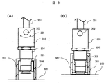
- FIG. 3 is a diagram relating to a suction unit which is a sheet separating unit in the present invention.
- A shows a state where paper is not adsorbed
- B shows a state where paper is adsorbed.
- a movable skirt 306 having a cylindrical inner wall is provided to cover the suction nozzle 307 with respect to the suction portion (here, the tip of the movable skirt 306 is sucked).
- the shape of the movable skirt 306 may be a polygonal shape such as a polygon.
- the movable skirt 306 slides up and down (in its own weight direction) with respect to the movable skirt receiving portion 305. Further, the movable skirt 306 has claws for catching on the movable skirt receiving portion 305 so as not to fall, and the lower limit of the slide is provided as shown in FIG.
- the suction nozzle 307 is connected to a suction hose 301 via a suction nozzle mounting member 304, and the suction hose 301 is a vacuum pump (not shown) that is a vacuum source via a valve for adjusting the leak amount. )It is connected to the.
- a valve for adjusting the amount of leak is provided to increase the responsiveness when releasing the adsorption. There is no need to provide such a valve as long as the output of the vacuum pump is not large and the adsorption is released as soon as it is turned off.
- the suction target is a flexible paper
- various deformations may occur, and there is a possibility that a gap is formed between the suction nozzle 307 and the suction target. Therefore, the suction nozzle 307 is configured by a member having flexibility that can follow the deformation of the paper that is the suction target at the suction tip portion.
- a material such as a rubber pad that can easily follow the deformation of paper is desirable.
- the suction portion is attached to the shaft 302 by using the suction portion attaching member 303 and can freely rotate with respect to the rotation direction 308 of the shaft 302. By doing so, when the booklet is conveyed while the first sheet is adsorbed by the adsorption nozzle 307, the booklet is automatically rotated in accordance with the conveyance.
- the movable skirt 306 slides until the suction nozzle 307 and the paper 309 come into contact with each other.
- This sliding operation is activated actively or automatically depending on the proximity distance of the suction nozzle 307 at the time of suction.
- the suction unit is lowered by an actuator (not shown) until the suction nozzle 307 comes into contact with the paper 309, a sliding operation is actively performed and the state shown in FIG.
- the suction part is stopped at a position where the movable skirt 306 contacts the paper 309 and the suction nozzle 307 does not contact the paper 309, the inside of the movable skirt 306 is in a negative pressure state. , Slides automatically.
- the movable skirt 306 and the movable skirt receiving portion 305 are made of a material having high lubricity so as not to hinder the automatic sliding operation.
- a material having high lubricity so as not to hinder the automatic sliding operation.
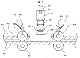
- FIG. 4 is a side view of the booklet page turning apparatus 106 of the present invention.
- the booklet page turning device 106 includes a suction unit 307 and transport rollers 404 to 407 as booklet transport means.
- the booklet is transported by transport rollers 404 to 407 along a transport path 402 formed by the upper transport guide 401 and the lower transport guide 403.
- the upper conveying rollers 404 and 406 are given a predetermined pressing force by springs 408 and 409 and are pressed against the lower conveying rollers 405 and 407.
- these transport rollers 404 to 407 use rollers having a rubber-like elastic layer on the surface. Due to the deformation of the elastic layer of the roller and the movement of the roller pressed by the above-described spring or the like, relatively stable conveyance can be realized even for booklets having different thicknesses.
- an elastic layer is provided on all the transport rollers 404 to 407. This is to increase the coefficient of friction between the booklet and the roller and realize more stable booklet conveyance.
- the elastic layer can be stably transported and transported between the rollers even if one of the elastic layers is not formed.
- the booklet page turning apparatus includes page holding members 410 and 411 in order to turn over the pages picked up and held by the suction unit. While the adsorbed and lifted pages are held by the page holding members 410 and 411, the booklet is conveyed by the booklet conveying means, and the page is turned.
- the page holding members 410 and 411 also have a purpose of preventing the turned-up pages from coming into contact with the upper transport rollers 404 and 406 and causing scratches or roller marks, so that the surface on the suction portion side is transported. It is desirable to exist inside the rollers 404 and 406. Furthermore, when the page to be turned is turned after holding the page to be turned by the page holding members 410 and 411, the page is turned in the space between the suction portion and the page holding member. As described above, it is necessary to secure a sufficient space for turning the page between the conveying rollers 404 and 406 and between the suction rollers.
- the booklet page turning apparatus of the present embodiment shown in the figure has an adsorbing portion so that page turning can be performed in the same way in both directions from the binding side to the opening side and from the opening side to the binding side. It is the left and right target as the center. Thus, in the page turning operation, it is possible to turn the page in any direction only by changing the control of the booklet stop position and the conveyance direction.
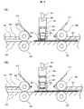
- FIG. 5 is a diagram illustrating the proximity distance during the suction operation of the booklet page turning apparatus according to the present embodiment.
- the proximity distance of the suction nozzle 307 includes 0, that is, contact, depending on the paper quality (paper rigidity, air permeability) of the paper to be suctioned / separated. Switching to a plurality of control distances is possible.
- the distance between the suction nozzle 307 and the first booklet 501 is controlled by lowering the shaft 302 by an actuator (not shown) (suction nozzle suction distance control mechanism).
- FIG. 5 (A) shows the proximity distance of the suction nozzle 307 when adsorbing to paper having high paper rigidity but low air permeability like a passbook cover.
- the suction part is lowered by the suction nozzle suction distance control mechanism, the movable skirt 306 is actively slid, and the suction nozzle 307 is pressed against the first sheet of the booklet 501 to be firmly sucked, To secure the necessary suction force for lifting.
- FIG. 5B shows the proximity distance of the suction nozzle 307 when sucking against paper having a low paper rigidity but high air permeability, such as a passbook paper.
- the suction part is lowered by the suction nozzle suction distance control mechanism, the suction nozzle 307 does not contact the first sheet of the booklet 501, and the movable skirt 306 contacts the first sheet of the booklet 501. (See FIG. 5B).
- the suction portion is stopped at a position where the movable skirt 306 contacts without pressing the suction nozzle 307.
- the suction pressure inside the chamber of the movable skirt 306 caused by the contact between the movable skirt 306 and the booklet 501 operates the movable skirt 306 as soon as a force necessary to lift the booklet 501 is generated. It does not become larger than the suction pressure inside the chamber when it is pressed.
- the suction nozzle 307 is made of a flexible member that can follow the deformation of the sheet to be sucked, such as a rubber pad, at the suction tip, whereas the movable skirt 306 has a tip made of a rubber pad or the like. This is because it is made up of a member that has little follow-up to sheet deformation. Further, a slight gap is provided between the movable skirt 306 and the skirt receiving portion 305 to reduce the suction pressure inside the chamber of the movable skirt 306.
- the suction section is a position where the suction nozzle 307 does not contact the first sheet and the movable skirt 306 contacts. Just stop. Therefore, if the movable range of the movable skirt 306 is sufficiently increased with respect to the booklet thickness, the control of the mechanism accuracy and the proximity distance can be simplified, leading to a reduction in apparatus cost. Further, since the same operation may be performed even if the booklet thickness is different, it is not necessary to adjust the height of the booklet thickness for each page, and adsorption and separation can be performed by a simple mechanism.
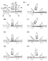
- FIGS. 6A to 6G show the operation for the passbook cover page, that is, the first page of the passbook.
- a bar code indicating the booklet size (the difference between the closed size and the open size) page number (usually the upper left of the passbook page) is selected and executed depending on whether it is a passbook cover page or a passbook intermediate page.
- the booklet 501 inserted from the insertion port 102 of the booklet printer 101 is page-turned to a predetermined position by the conveyance rollers 404 to 407 and is conveyed and stopped.
- the predetermined position is a position where the binding side of the booklet 501 can be sandwiched by the transport rollers 406 and 407
- the booklet opening side is a position where the booklet 501 is not sandwiched by the transport rollers (see FIG. 6A).
- a vacuum source (not shown) is actuated to turn off a valve for adjusting the leak amount, and then the suction portion is lowered in the direction of arrow 601.
- the tip of the movable skirt 306 contacts the booklet 501 as shown in FIG.
- the passbook cover has high rigidity, it is not lifted up substantially by the suction force of the movable skirt 306.
- the material / structure of the movable skirt 306 is configured so that the suction force of the movable skirt 306 is such that the passbook cover does not substantially lift.
- the suction part is further lowered in the direction of the arrow 601, and the first sheet is sucked.
- the suction portion is lowered until the suction nozzle 307 contacts the first sheet of the booklet 501 (see FIG. 6B).
- the lower end of the movable skirt 306 may be configured to have the same height as the suction portion before the suction portion is lowered in the arrow 601 direction. That is, the suction nozzle 307 may suck the first passbook cover without causing the phenomenon that the tip of the movable skirt 306 contacts the booklet 501.
- the suction part is moved in the direction of the arrow 602 to lift the first sheet.
- the page lifting amount is equal to the lower end of the page holding member 410 (upper conveyance guide 401). ) Higher position is desirable.
- the remaining booklet 501 is conveyed to the booklet opening side by the conveying rollers 406 and 407 while the first sheet is held by the suction nozzle 307.
- the suction portion mounting member 303 is freely attached to the suction portion shaft 302 in the rotational direction, the suction portion shaft 302 automatically moves in the direction of the arrow 603 so that the suction portion follows the transport direction. And rotate.
- the suction of the suction nozzle 307 and the first sheet is released by stopping a vacuum source (not shown) and turning on a valve for adjusting the leak amount.
- the first sheet is peeled off from the suction nozzle 307 and supported by the page support (see FIG. 6F).
- the suction unit shaft 302 rotates in the direction of the arrow 604 due to its own weight and returns to the initial position.
- the movable skirt 306 returns to the initial position by its own weight.
- the booklet 501 inserted from the insertion port 102 of the booklet printer 101 is turned to a predetermined page turning position by the transport rollers 404 to 407. 402 is transported and stopped.
- a vacuum source (not shown) is actuated to turn off a valve for adjusting the leak amount, and then the suction portion is lowered in the direction of arrow 601.
- the suction nozzle 307 does not contact the first sheet of the booklet 501, and the movable skirt 306 of the booklet 501 does not contact the suction part. Lower until contact with the first sheet (see FIG. 7B).
- the movable skirt 306 slides automatically, and only the first sheet to be sucked / separated is lifted, and only the first sheet can be sucked by the suction nozzle 307 (see FIG. 7C). .
- the suction part is moved in the direction of the arrow 602 to lift the first sheet.
- the page lifting amount is higher than the lower end (upper conveyance guide 401) of the page holding member 410.
- the remaining booklet 501 is conveyed to the booklet opening side by the conveying rollers 406 and 407 while the first sheet is held by the suction nozzle 307.
- the suction portion mounting member 303 is freely attached to the suction portion shaft 302 in the rotational direction, the suction portion shaft 302 automatically moves in the direction of the arrow 603 so that the suction portion follows the transport direction. And rotate.
- the suction of the suction nozzle 307 and the first sheet is released by stopping a vacuum source (not shown) and turning on a valve for adjusting the leak amount.
- the first sheet is peeled off from the suction nozzle 307 and supported by the page support (see FIG. 7G).
- the suction unit shaft 302 rotates in the direction of the arrow 604 due to its own weight and returns to the initial position.
- the movable skirt 306 returns to the initial position by its own weight.
- the present embodiment has a bilaterally symmetric structure. Therefore, it is possible to turn the page to the right side by performing the same operation.
- Fig. 8 shows the movable skirt return mechanism.
- the movable skirt 306 is lifted to be in the state shown in FIG.
- the weight returns to the initial state (see FIG. 3A), but if the sliding of the slide becomes worse due to dust or the like, the weight may not return to the initial state. Therefore, as shown in FIG. 8, movable skirt return members 801 and 802 for returning the movable skirt to the initial state may be provided. Since the movable skirt 306 is forcibly pushed down by the movable skirt return members 801 and 802 by raising the suction portion from the state of FIG. 8, it can be surely returned to the initial state.
- the movable skirt return members 801 and 802 are desirably members such as leaf springs having flexibility so as not to apply an abnormal force to the movable skirt.
- a suction nozzle for sucking paper and a movable skirt for covering the suction nozzle are provided, and a paper with high rigidity and low air permeability such as a passbook cover is used for suction. Then, the page is lifted by bringing the suction nozzle into close contact.
- a paper with high rigidity and low air permeability such as passbook paper
- the suction nozzle does not adhere to the paper, and the suction nozzle is placed at the position where the movable skirt that covers the suction nozzle contacts. Stop.
- the passbook cover can lift the paper without losing the rigidity of the paper by firmly adsorbing the suction nozzle.
- the suction force is increased by 2 sheets as the negative pressure decreases in the movable skirt.
- the first sheet can be sucked by the suction nozzle, and the first and second sheets can be separated.
- a page holding member and a booklet conveying unit are provided, and the first sheet separated from the booklet by the paper separating unit is held by the page holding member and conveyed by the booklet conveying unit, so that the first sheet is turned over.
- a booklet page turning apparatus capable of separating and turning over the first sheet from a sheet bundle made of different paper quality with a relatively simple configuration without requiring complicated movement.
Landscapes
- Engineering & Computer Science (AREA)
- Mechanical Engineering (AREA)
- Sheets, Magazines, And Separation Thereof (AREA)
Abstract
Description
84号公報に記載されている。
、紙を落としてしまうという危険性がある。
切替可能に構成される。
気透過性の小さい紙が用いられ、表紙と裏表紙との間には柔らかく(剛性の低い)、空気
透過性の大きい紙が用いられている。
吸着していない状態を示し、(B)は、紙を吸着している状態を示す。
な形状でも構わないが、可動スカート306が紙と接触した際に可動スカート306と紙との間の隙間を減らすために周の長さが小さく、吸引力を大きくするために面積が大きい方がよい。そのため、円筒形状であることが望ましい。そして、可動スカート306は、可動スカート受け部305に対して上下(自重方向)にスライドする。また、可動スカート306は、落下しないように、可動スカート受け部305に引っかかるための爪を有しており、スライドの下限が図3(A)に示すよう設けられている。
、その吸着先端部に、吸着対象である用紙の変形に追従可能な柔軟性を有する部材により構成される。例えば、ゴムパッドのような容易に紙の変形に追従できる素材が望ましい。
、吸着ノズル307と紙309が接触するまでスライドする。このスライド動作は、吸着時の吸着ノズル307の近接距離によって、能動的または自動的に動作する。吸着部を、吸着ノズル307が、紙309と接触するまで図示しないアクチュエータで下ろした場合は、能動的にスライド動作を起こし、図3(B)に示す状態となる。一方、吸着部を可動スカート306が紙309と接触し、且つ吸着ノズル307が紙309と接触しない位置で停止させた場合は、可動スカート306内部が負圧状態となるため、紙を吸着したまま
、自動的にスライドする。そして、吸着ノズル307に紙309が接触し、しっかりと吸着・保持し、図3(B)に示す状態となる。したがって、可動スカート306と可動スカート受け部305は、上記自動スライド動作の妨げとならないよう、潤滑性の高い素材より構成されることが望ましい。例えば、軽量で安価な樹脂素材やテフロン(登録商標)コーティング材といいた素材から構成されることが望ましい。
、搬送ローラ404,406よりも内側に存在し、かつ吸着部との間にページをめくり返すのに十分なスペースを確保する必要がある。
、空気透過性)によって吸着ノズル307の近接距離を0つまり接触も含む、複数の制御
距離に切替可能である。図示しないアクチュエータにより軸302を下げる(吸着ノズル吸着距離制御機構)ことで、吸着ノズル307と冊子501の1枚目との距離を制御する
。
うと吸引力が2枚目以降のページに伝わってしまい、多重吸着につながる。そこで、本実施例では、吸着ノズル307を押しつけず、可動スカート306が接触する位置にて吸着部を停止させる。
透過性が小さいため、吸着部を吸着ノズル307が冊子501の1枚目と接触するまで下
ろす(図6(B)参照)。
)よりも高い位置が望ましい。
によって矢印604方向へ吸着部軸302が回転し、初期位置へと戻る。そして、可動スカート306も同様に自重によって、初期位置へと戻る。
、前記したように剛性が小さく、空気透過性が大きいため、吸着部を吸着ノズル307が冊子501の1枚目と接触せず、可動スカート306が冊子501の1枚目と接触するまで下ろす(図7(B)参照)。
、搬送ローラ406,407によって残りの冊子501を冊子開き側へ搬送する。この時
、吸引部取付部材303は、吸着部軸302に対して回転方向に自由に取り付けられているため、吸着部は搬送方向に追従するよう、吸着部軸302が自動的に矢印603方向へと回転する。
によって矢印604方向へ吸着部軸302が回転し、初期位置へと戻る。そして、可動スカート306も同様に自重によって、初期位置へと戻る。
、1枚目をめくり返すことができる。したがって、複雑な動きを必要とすることなく、比較的簡単な構成で、異なる紙質からなる用紙束より1枚目を分離し、めくり返すことが可能な冊子ページめくり装置を提供することができる。
102 挿入口
103 搬送路
104 冊子読取部
105 印字機構部
106 ページめくり部
115a,115b,115c,115d,115e,115f,115g,115h,115g 搬送ローラ
113 下側搬送ガイド
114 上側搬送ガイド
116 制御部
201 本体制御部
301 吸引ホース
302 吸引部軸
303 吸引部取付部材
304 吸着ノズル取付部材
305 可動スカート受け部
306 可動スカート
307 吸着ノズル
308 吸引部軸回転方向
309 紙
401 冊子ページめくり装置部上側搬送ガイド
402 冊子ページめくり装置部搬送路
403 冊子ページめくり装置部下側搬送ガイド
404,405,406,407 搬送ローラ
408,409 ばね
410,411 ページ保持部材
501 冊子
601 吸着部吸着方向
602 吸着部持ち上げ方向
603,604 吸着部回転方向
801,802 可動スカート戻し部材
Claims (9)
- 用紙束から所定の頁を吸引することで分離する用紙分離機構を有し、前記用紙分離機構で分離した頁をめくるように構成された冊子ページめくり装置であって、前記用紙分離機構は、用紙を吸着する吸着ノズルと、前記吸着ノズルを覆う可動スカートを有し、前記吸着ノズルと前記可動スカートの吸着部に所定の距離を設けて前記可動スカートを用紙に近接させて前記可動スカートで前記用紙を吸着させる第1の吸着と、前記吸着ノズルを用紙に近接させて前記第1の吸着よりも強い吸着力で吸着させる第2の吸着とを選択可能に行うよう構成されることを特徴とする冊子ページめくり装置。
- 請求項1において、前記第2の吸着は第1枚頁目に対してなされ、前記吸着ノズルと吸
着する用紙表面との間に一定の距離を設けて近接させるように、前記吸着ノズルの位置を制御する吸着ノズル距離制御機構を有することを特徴とする冊子ページめくり装置。 - 請求項2において、前記吸着ノズル距離制御手段機構は、制御する前記吸着ノズルと吸着する用紙表面との間の近接距離を、吸着対象である用紙の硬さ,空気透過性などの用紙の物性値のうち少なくとも一つ以上により、近接距離0である接触も含む、複数の制御距
離に切替可能に構成された制御機構であることを特徴とする冊子ページめくり装置。 - 請求項2記載の冊子ページめくり装置において、前記可動スカートは、可動方向である前記吸着ノズル吸引方向である用紙の吸着方向における可動負荷を小さくするために、潤滑性の高い素材より構成されることを特徴とする冊子ページめくり装置。
- 請求項2記載の冊子ページめくり装置において、前記可動スカートは、前記吸着ノズルを囲むよう内壁が円筒形状を成すことを特徴とする冊子ページめくり装置。
- 請求項2記載の冊子ページめくり装置において、前記吸着ノズルは、その吸着先端部に
、ゴムパッドなどの吸着対象である用紙の変形に追従可能な柔軟性を有する部材を具備することを特徴とする冊子ページめくり装置。 - 請求項1記載の冊子ページめくり装置において、前記吸着ノズルによって吸着、分離した1枚目をめくり返すためのページ保持部材および冊子搬送構造を有し、ページめくりを行う際に、前記吸着ノズルによって吸着、分離した1枚目を前記冊子搬送構造にて冊子を搬送しながら前記吸着ノズルの吸引源を停止することで、前記ページ保持部材に1枚目を保持させ、前記冊子搬送構造により冊子を搬送することで1枚目をめくり返すことを特徴とする冊子ページめくり装置。
- 用紙の集まりから所定の用紙を吸引することで分離する用紙分離装置であって、前記用紙を吸着する吸着ノズルと、前記吸着ノズルを覆う可動スカートを有し、前記吸着ノズルと前記可動スカートの吸着部に所定の距離を設けて前記可動スカートを用紙に近接させて前記可動スカートで前記用紙を吸着させる第1の吸着と、前記吸着ノズルを用紙に近接させて前記第1の吸着よりも強い吸着力で吸着させる第2の吸着とを選択可能に行うよう構成される用紙分離装置。
- 吸着ノズルと前記可動スカートの吸着部に所定の距離を設けて前記可動スカートを前記用紙に近接させて前記可動スカートで用紙を吸着させる第1の吸着と、前記吸着ノズルを用紙に近接させて前記第1の吸着よりも強い吸着力で吸着させる第2の吸着とを選択可能に行い、前記吸着させた用紙を前記吸着ノズルと共に動かすことで用紙を分離する用紙分離方法。
Priority Applications (1)
| Application Number | Priority Date | Filing Date | Title |
|---|---|---|---|
| KR1020187017522A KR102068429B1 (ko) | 2016-06-14 | 2017-03-02 | 용지 분리 장치, 페이지 넘김 장치 및 용지 분리 방법 |
Applications Claiming Priority (2)
| Application Number | Priority Date | Filing Date | Title |
|---|---|---|---|
| JP2016117582A JP6735609B2 (ja) | 2016-06-14 | 2016-06-14 | 用紙分離装置、ページめくり装置、及び、用紙分離方法 |
| JP2016-117582 | 2016-06-14 |
Publications (1)
| Publication Number | Publication Date |
|---|---|
| WO2017217030A1 true WO2017217030A1 (ja) | 2017-12-21 |
Family
ID=60664567
Family Applications (1)
| Application Number | Title | Priority Date | Filing Date |
|---|---|---|---|
| PCT/JP2017/008302 Ceased WO2017217030A1 (ja) | 2016-06-14 | 2017-03-02 | 用紙分離装置、ページめくり装置、及び、用紙分離方法 |
Country Status (3)
| Country | Link |
|---|---|
| JP (1) | JP6735609B2 (ja) |
| KR (1) | KR102068429B1 (ja) |
| WO (1) | WO2017217030A1 (ja) |
Cited By (1)
| Publication number | Priority date | Publication date | Assignee | Title |
|---|---|---|---|---|
| CN108366180A (zh) * | 2018-05-08 | 2018-08-03 | 无锡中育科教技术有限公司 | 一种纸张拍照的自动翻页装置 |
Citations (5)
| Publication number | Priority date | Publication date | Assignee | Title |
|---|---|---|---|---|
| US3154306A (en) * | 1962-10-29 | 1964-10-27 | Harris Intertype Corp | Sheet-gripping sucker |
| JPS57175634A (en) * | 1981-04-21 | 1982-10-28 | Matsushita Electric Ind Co Ltd | Paper feeding device |
| JPS645891A (en) * | 1987-06-29 | 1989-01-10 | Sony Corp | Page turn-over device |
| JPH02127088A (ja) * | 1988-11-07 | 1990-05-15 | Nec Corp | 通帳自動処理装置 |
| JP2004231379A (ja) * | 2003-01-31 | 2004-08-19 | Fuji Photo Film Co Ltd | 印刷版の吸着盤 |
Family Cites Families (4)
| Publication number | Priority date | Publication date | Assignee | Title |
|---|---|---|---|---|
| JPH05162484A (ja) | 1991-12-13 | 1993-06-29 | Sharp Corp | 吸着式ページめくり装置 |
| JP2000128372A (ja) * | 1998-10-27 | 2000-05-09 | Matsushita Electric Works Ltd | シート材の分離・搬送装置 |
| JP4100152B2 (ja) | 2002-12-03 | 2008-06-11 | 松下電器産業株式会社 | 電子部品吸着用ノズル |
| KR101337116B1 (ko) | 2010-09-08 | 2013-12-05 | 가부시끼가이샤 도시바 | 책자의 페이지 넘김 장치 |
-
2016
- 2016-06-14 JP JP2016117582A patent/JP6735609B2/ja active Active
-
2017
- 2017-03-02 KR KR1020187017522A patent/KR102068429B1/ko active Active
- 2017-03-02 WO PCT/JP2017/008302 patent/WO2017217030A1/ja not_active Ceased
Patent Citations (5)
| Publication number | Priority date | Publication date | Assignee | Title |
|---|---|---|---|---|
| US3154306A (en) * | 1962-10-29 | 1964-10-27 | Harris Intertype Corp | Sheet-gripping sucker |
| JPS57175634A (en) * | 1981-04-21 | 1982-10-28 | Matsushita Electric Ind Co Ltd | Paper feeding device |
| JPS645891A (en) * | 1987-06-29 | 1989-01-10 | Sony Corp | Page turn-over device |
| JPH02127088A (ja) * | 1988-11-07 | 1990-05-15 | Nec Corp | 通帳自動処理装置 |
| JP2004231379A (ja) * | 2003-01-31 | 2004-08-19 | Fuji Photo Film Co Ltd | 印刷版の吸着盤 |
Cited By (1)
| Publication number | Priority date | Publication date | Assignee | Title |
|---|---|---|---|---|
| CN108366180A (zh) * | 2018-05-08 | 2018-08-03 | 无锡中育科教技术有限公司 | 一种纸张拍照的自动翻页装置 |
Also Published As
| Publication number | Publication date |
|---|---|
| KR20180086454A (ko) | 2018-07-31 |
| JP6735609B2 (ja) | 2020-08-05 |
| KR102068429B1 (ko) | 2020-01-20 |
| JP2017222052A (ja) | 2017-12-21 |
Similar Documents
| Publication | Publication Date | Title |
|---|---|---|
| US6776405B2 (en) | Imaging apparatus and methods | |
| US20120055755A1 (en) | Booklet page turning apparatus | |
| JP6735609B2 (ja) | 用紙分離装置、ページめくり装置、及び、用紙分離方法 | |
| US9527685B2 (en) | Feeding apparatus and image forming apparatus | |
| CN1323914C (zh) | 介质传送机构、介质传送装置和介质传送方法 | |
| KR101195738B1 (ko) | 소책자 페이지 넘김 장치, 소책자 페이지 넘김 방법 및 소책자 처리 장치 | |
| JPH11349188A (ja) | 通帳類取扱装置 | |
| JP4317054B2 (ja) | シート搬送装置 | |
| JP5631672B2 (ja) | 冊子の頁捲り装置 | |
| US6843476B2 (en) | Print Media Stack Clamp | |
| TWI608981B (zh) | 主動式取紙分紙機構 | |
| JP6579937B2 (ja) | 冊子ページめくり装置及び冊子プリンタ | |
| JP2007331905A (ja) | 給紙装置とその制御方法およびこれを用いた印刷装置 | |
| KR100885823B1 (ko) | 장표용 자세 정규화 장치 | |
| JP5150844B2 (ja) | 給紙装置 | |
| JP2728403B2 (ja) | 紙送り装置 | |
| JP4328809B2 (ja) | 印刷媒体送り機構及びこれを備えたプリンタ | |
| JP2002173233A (ja) | シート給送装置及びこれを備えた画像形成装置 | |
| JPH02291324A (ja) | 自動給紙機構 | |
| JP6438383B2 (ja) | 媒体プリンタ | |
| JPH1111726A (ja) | シート材の分離方法及びその装置 | |
| JP2004051334A (ja) | シート給送装置、記録装置 | |
| JPH1111710A (ja) | シート材の分離方法及びその装置 | |
| WO1998012052A1 (fr) | Imprimante et unite d'entrainement de support | |
| JPH047225A (ja) | 画像形成装置における給紙装置 |
Legal Events
| Date | Code | Title | Description |
|---|---|---|---|
| ENP | Entry into the national phase |
Ref document number: 20187017522 Country of ref document: KR Kind code of ref document: A |
|
| WWE | Wipo information: entry into national phase |
Ref document number: 1020187017522 Country of ref document: KR |
|
| 121 | Ep: the epo has been informed by wipo that ep was designated in this application |
Ref document number: 17812939 Country of ref document: EP Kind code of ref document: A1 |
|
| NENP | Non-entry into the national phase |
Ref country code: DE |
|
| 122 | Ep: pct application non-entry in european phase |
Ref document number: 17812939 Country of ref document: EP Kind code of ref document: A1 |