WO2017213144A1 - 基板ユニット - Google Patents
基板ユニット Download PDFInfo
- Publication number
- WO2017213144A1 WO2017213144A1 PCT/JP2017/021002 JP2017021002W WO2017213144A1 WO 2017213144 A1 WO2017213144 A1 WO 2017213144A1 JP 2017021002 W JP2017021002 W JP 2017021002W WO 2017213144 A1 WO2017213144 A1 WO 2017213144A1
- Authority
- WO
- WIPO (PCT)
- Prior art keywords
- connector
- case
- circuit board
- region
- facing
- Prior art date
Links
Images


Classifications
-
- H—ELECTRICITY
- H05—ELECTRIC TECHNIQUES NOT OTHERWISE PROVIDED FOR
- H05K—PRINTED CIRCUITS; CASINGS OR CONSTRUCTIONAL DETAILS OF ELECTRIC APPARATUS; MANUFACTURE OF ASSEMBLAGES OF ELECTRICAL COMPONENTS
- H05K5/00—Casings, cabinets or drawers for electric apparatus
- H05K5/0026—Casings, cabinets or drawers for electric apparatus provided with connectors and printed circuit boards [PCB], e.g. automotive electronic control units
- H05K5/0047—Casings, cabinets or drawers for electric apparatus provided with connectors and printed circuit boards [PCB], e.g. automotive electronic control units having a two-part housing enclosing a PCB
- H05K5/0056—Casings, cabinets or drawers for electric apparatus provided with connectors and printed circuit boards [PCB], e.g. automotive electronic control units having a two-part housing enclosing a PCB characterized by features for protecting electronic components against vibration and moisture, e.g. potting, holders for relatively large capacitors
-
- H—ELECTRICITY
- H01—ELECTRIC ELEMENTS
- H01R—ELECTRICALLY-CONDUCTIVE CONNECTIONS; STRUCTURAL ASSOCIATIONS OF A PLURALITY OF MUTUALLY-INSULATED ELECTRICAL CONNECTING ELEMENTS; COUPLING DEVICES; CURRENT COLLECTORS
- H01R13/00—Details of coupling devices of the kinds covered by groups H01R12/70 or H01R24/00 - H01R33/00
- H01R13/46—Bases; Cases
- H01R13/52—Dustproof, splashproof, drip-proof, waterproof, or flameproof cases
- H01R13/5227—Dustproof, splashproof, drip-proof, waterproof, or flameproof cases with evacuation of penetrating liquids
-
- H—ELECTRICITY
- H05—ELECTRIC TECHNIQUES NOT OTHERWISE PROVIDED FOR
- H05K—PRINTED CIRCUITS; CASINGS OR CONSTRUCTIONAL DETAILS OF ELECTRIC APPARATUS; MANUFACTURE OF ASSEMBLAGES OF ELECTRICAL COMPONENTS
- H05K5/00—Casings, cabinets or drawers for electric apparatus
-
- H—ELECTRICITY
- H05—ELECTRIC TECHNIQUES NOT OTHERWISE PROVIDED FOR
- H05K—PRINTED CIRCUITS; CASINGS OR CONSTRUCTIONAL DETAILS OF ELECTRIC APPARATUS; MANUFACTURE OF ASSEMBLAGES OF ELECTRICAL COMPONENTS
- H05K5/00—Casings, cabinets or drawers for electric apparatus
- H05K5/0026—Casings, cabinets or drawers for electric apparatus provided with connectors and printed circuit boards [PCB], e.g. automotive electronic control units
- H05K5/0047—Casings, cabinets or drawers for electric apparatus provided with connectors and printed circuit boards [PCB], e.g. automotive electronic control units having a two-part housing enclosing a PCB
- H05K5/0052—Casings, cabinets or drawers for electric apparatus provided with connectors and printed circuit boards [PCB], e.g. automotive electronic control units having a two-part housing enclosing a PCB characterized by joining features of the housing parts
-
- H—ELECTRICITY
- H05—ELECTRIC TECHNIQUES NOT OTHERWISE PROVIDED FOR
- H05K—PRINTED CIRCUITS; CASINGS OR CONSTRUCTIONAL DETAILS OF ELECTRIC APPARATUS; MANUFACTURE OF ASSEMBLAGES OF ELECTRICAL COMPONENTS
- H05K5/00—Casings, cabinets or drawers for electric apparatus
- H05K5/0026—Casings, cabinets or drawers for electric apparatus provided with connectors and printed circuit boards [PCB], e.g. automotive electronic control units
- H05K5/0069—Casings, cabinets or drawers for electric apparatus provided with connectors and printed circuit boards [PCB], e.g. automotive electronic control units having connector relating features for connecting the connector pins with the PCB or for mounting the connector body with the housing
-
- H—ELECTRICITY
- H05—ELECTRIC TECHNIQUES NOT OTHERWISE PROVIDED FOR
- H05K—PRINTED CIRCUITS; CASINGS OR CONSTRUCTIONAL DETAILS OF ELECTRIC APPARATUS; MANUFACTURE OF ASSEMBLAGES OF ELECTRICAL COMPONENTS
- H05K5/00—Casings, cabinets or drawers for electric apparatus
- H05K5/02—Details
-
- H—ELECTRICITY
- H05—ELECTRIC TECHNIQUES NOT OTHERWISE PROVIDED FOR
- H05K—PRINTED CIRCUITS; CASINGS OR CONSTRUCTIONAL DETAILS OF ELECTRIC APPARATUS; MANUFACTURE OF ASSEMBLAGES OF ELECTRICAL COMPONENTS
- H05K5/00—Casings, cabinets or drawers for electric apparatus
- H05K5/0026—Casings, cabinets or drawers for electric apparatus provided with connectors and printed circuit boards [PCB], e.g. automotive electronic control units
- H05K5/0047—Casings, cabinets or drawers for electric apparatus provided with connectors and printed circuit boards [PCB], e.g. automotive electronic control units having a two-part housing enclosing a PCB
- H05K5/006—Casings, cabinets or drawers for electric apparatus provided with connectors and printed circuit boards [PCB], e.g. automotive electronic control units having a two-part housing enclosing a PCB characterized by features for holding the PCB within the housing
Definitions
- the present invention relates to a substrate unit.
- This application claims priority based on Japanese Patent Application No. 2016-114857 filed on Jun. 8, 2016, and incorporates all the contents described in the above Japanese application.
- a vehicle-mounted case or the like that houses an electrical device is provided with a waterproof structure that prevents a failure of the electrical device that is a contained object due to water intrusion.
- the substrate unit according to the present disclosure is: A circuit board; A connector portion mounted on the circuit board; A board unit comprising a case for housing the circuit board,
- the case is A lower case having an accommodating part that opens upward and accommodates the circuit board;
- An upper cover that covers the storage portion of the lower case;
- the connector part is provided with an opening that is open to the side wall of the case so that the connector part can be fitted with the mating connector part,
- the upper cover is A ceiling portion having a board facing area facing the circuit board housed in the housing section, and an outer area located outside the board facing area without facing the circuit board; And a guide groove that is inclined from the substrate facing region to the outer region and guides water droplets present in the substrate facing region to the outer region and discharges them to the outside of the circuit board.
- FIG. 1 is a perspective view illustrating an outline of a substrate unit according to Embodiment 1.
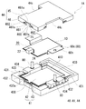
- FIG. 2 is an exploded perspective view showing an outline of a substrate unit according to Embodiment 1.
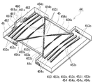
- FIG. 3 is a perspective view illustrating an outline of a lower surface of an upper cover provided in the substrate unit according to Embodiment 1.
- FIG. 3 is a bottom view illustrating an outline of a lower surface of an upper cover provided in the substrate unit according to the first embodiment.
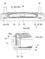
- FIG. 2 is a cross-sectional view showing a state in which the substrate unit shown in FIG. 1 is cut along a (V)-(V) cutting line. It is a perspective view which shows the outline of the waterproof wall part and inner wall part of the lower case with which the board
- an object of the present invention is to provide a board unit that can suppress the adhesion of water droplets to an internal circuit board with a simple configuration.
- the board unit of this indication can control adhesion of a water drop to an internal circuit board by simple composition.
- a substrate unit includes: A circuit board; A connector portion mounted on the circuit board; A board unit comprising a case for housing the circuit board,
- the case is A lower case having an accommodating part that opens upward and accommodates the circuit board;
- An upper cover that covers the storage portion of the lower case;
- the connector part is provided with an opening that is open to the side wall of the case so that the connector part can be fitted with the mating connector part,
- the upper cover is A ceiling portion having a board facing area facing the circuit board housed in the housing section, and an outer area located outside the board facing area without facing the circuit board; And a guide groove that is inclined from the substrate facing region to the outer region and guides water droplets present in the substrate facing region to the outer region and discharges them to the outside of the circuit board.
- the upper cover includes the guide groove.
- the water droplets adhering to the substrate facing area on the back surface (lower surface) of the upper cover can be guided to the outside area by the guide groove and discharged to the outside of the circuit board, and the water droplet can be prevented from dropping onto the circuit board. Therefore, a waterproof member such as a waterproof ring may not be provided separately. Thereby, the number of parts can be reduced, and the assembly workability of the board unit can be improved.
- the water droplets present in the substrate facing region are considered to be (1) water droplets that have entered the interior from the outside of the case (intrusion water) and (2) water droplets (condensation water) that are formed by condensation of water vapor inside the case.
- the intrusion water or dew condensation water enters the guide groove along the lower surface of the upper cover, is guided to the outer region, and is discharged to the outside of the circuit board.
- the board facing area has a connector facing area facing the connector portion, and the guide groove is formed from the connector facing area to the outer area.
- water droplets existing in the substrate facing region are often water droplets that have entered the interior from an opening formed in the side wall of the case, as compared to water droplets that have condensed. Therefore, by forming a guide groove in the connector facing area close to the opening (water droplet inlet), it is possible to guide the infiltrated water droplet to the outer area near the opening, and the back of the water drop case (board facing) This is because it is easy to prevent entry into the region.
- the ceiling portion is formed from the connector facing region to the outer region, and has an inclined rib whose height increases from the connector facing region toward the outer region,
- the guide groove is formed on an end surface of the rib.
- the lower case is A waterproof wall formed on the outer periphery of the storage part in the lower case to prevent water from entering the storage part from the outside of the case; An inner wall portion formed at an interval from the waterproof wall portion between the waterproof wall portion and the storage portion; The water droplet discharge port in the guide groove is provided so as to face between the waterproof wall portion and the inner wall portion,
- the waterproof wall portion includes a discharge portion that discharges the water droplet discharged between the waterproof wall portion and the waterproof wall portion.
- the water droplets discharged between the waterproof wall portion and the inner wall portion by the inner wall portion inside the waterproof wall portion can be prevented from flowing and adhering to the circuit board. Further, by providing the discharge portion, water droplets discharged between the waterproof wall portion and the inner wall portion can be discharged outside the waterproof wall portion without staying on the spot.
- Embodiment 1 [Board unit]
- the board unit 1 ⁇ / b> A includes a circuit board 10, a connector part 20 mounted on the circuit board 10, and a case 40 that houses the circuit board 10 and the connector part 20.
- the case 40 includes a lower case 41, an upper cover 44, and an opening 48 opened on the side wall of the case 40.
- the opening portion 48 is open so that the connector portion 20 can be fitted to a mating connector portion (not shown).
- the upper cover 44 includes a guide groove 453 that allows water droplets existing on the back surface (lower surface) of the upper cover 44 to be discharged to the outside of the circuit board 10 without dropping. .
- the lower case 41 side of the case 40 is the lower side
- the upper cover 44 side is the upper side
- the direction perpendicular to the vertical direction of the case 40 is the side where the connector unit 20 is disposed. Is the front side and the opposite side is the rear side.
- the direction orthogonal to both the up-down direction and the front-rear direction is defined as the left-right direction.
- the circuit board 10 mounts an electronic component (not shown) such as a semiconductor relay or a connector portion 20 (FIG. 2).
- the circuit board 10 includes an insulating substrate and a circuit (conductor) pattern (not shown) that is formed on one surface of the circuit board 10 and electrically connected to electronic components.
- the circuit board 10 can be a printed board.
- the connector unit 20 connects a mating connector unit (not shown) to the board unit 1A.
- the connector portion 20 includes a hood-like connector housing 22 that opens outward and can be fitted to the mating connector portion, and connector terminals 24 that extend from the inside of the connector housing 22 toward the circuit board 10 (FIG. 2). .
- the connector housing 22 is shown as a column for convenience of explanation.
- the connector terminal 24 is provided through the inner wall opposite to the opening of the connector housing 22, one end portion is disposed in the connector housing 22, and the other end portion is a conductive pattern formed on the circuit board 10. They are electrically connected (FIG. 2). This electrical connection can be performed by a known method such as soldering.
- the mating connector portion is connected to in-vehicle electrical components and the like via a wire harness.
- the case 40 accommodates the circuit board 10 (FIG. 2) and the connector part 20 inside.
- the case 40 is configured by combining a lower case 41 and an upper cover 44.
- an opening 48 is opened by the lower case 41 and the upper cover 44 so that the connector portion 20 can be fitted to the mating connector portion. 1) is formed.
- the connector portion 20 is positioned with respect to the case 40 by being sandwiched between the lower case 41 and the upper cover 44.
- the upper cover 44 covers the storage part 410 (FIG. 2) of the lower case 41 (FIG. 1).
- the upper cover 44 is an integrated body composed of a ceiling portion 45 that forms the upper surface of the case 40 and a side wall portion 46 that stands up shallow from the periphery of the ceiling portion 45.
- the upper cover 44 is formed so as to cover the upper portion of the lower case 41 with the base portion 434 of the lower case 41 exposed, and has a notch 44c in a part of the outer wall.
- the notch 44c ensures a gap through which the extended portion 60c of the bus bar 60 (described later) can pass even when the upper cover 44 is fixed to the lower case 41. By this gap, the extended portion 60 c of the bus bar 60 can be placed on the upper surface of the base portion 434.
- the ceiling portion 45 includes a substrate facing region 451 (see the outer edge of the two-dot chain line) facing the circuit substrate 10 housed in the housing portion 410, and a substrate facing region 451 that does not face the circuit substrate 10. And an outer region 452 located on the outer side.
- the shape of the ceiling portion 45 is a substantially rectangular flat plate shape, and the lower surface of the ceiling portion 45 is planar.
- the lower surface of the ceiling part 45 may be an inclined surface (triangular roof type) inclined downward from the center in the left-right direction toward both left and right sides.
- the shape of the substrate facing region 451 is the same rectangle as the shape of the circuit board 10.
- the outer region 452 has a substantially rectangular frame shape surrounding the substrate facing region 451.
- region 451 has the connector opposing area
- a guide groove 453 is formed on the lower surface of the ceiling portion 45 to prevent water droplets existing on the lower surface from falling on the circuit board 10 (FIGS. 3 and 4).
- a rib 454 is provided on the lower surface of the ceiling portion 45, and the guide groove 453 is formed in series on the lower surface of the ceiling portion 45 and the end surface of the rib 454.
- the guide groove 453 guides water droplets present in the substrate facing region 451 to the outer region 452 and discharges them to the outside of the circuit board 10. Thereby, it is possible to suppress the water droplets present in the board facing region 451 from dropping and adhering to the circuit board 10.
- the water droplets present in the substrate facing region 451 are (1) water droplets that have entered the interior from the outside of the case 40 (intrusion water), (2) water droplets that have been condensed by water vapor inside the case 40 (condensation water), Can be considered.
- Intrusion Water Drops applied to the case 40 travel along the surface of the case 40, flow toward the opening 48 formed on the side wall, and enter the inside of the case 40 from between the opening 48 and the connector portion 20. There are things to do.
- the guide groove 453 is formed to be inclined from the substrate facing region 451 to the outer region 452.
- Inclined formation means that the depth decreases from the substrate facing region 451 toward the outer region 452 and the depth is uniform from the substrate facing region 451 toward the outer region 452 as in this example.
- the guide groove 453 itself is inclined with respect to the horizontal direction by an inclined rib 454 described later.
- the number of guide grooves 453 may be singular or plural.
- the guide groove 453 is preferably provided at least in the vicinity of the opening 48, for example, from the connector facing region 451a of the substrate facing region 451 to the left and right outer regions 452. If it does so, it will be easy to prevent the water droplet which infiltrated in the case 40 to fall to the circuit board 10. Since the guide groove 453 is provided near the opening 48 that is the inlet of the water droplet in the case 40, the infiltrated water droplet can be guided to the outer region 452 in the vicinity of the inlet, and the water droplet can be moved to the back of the case 40. This is because it is easy to prevent the intrusion.
- the longitudinal direction of the guide groove 453 formed from the connector facing region 451a to the left and right outer regions 452 is preferably along the left-right direction. Then, since the guide groove 453 is formed in a straight line and the length to the outer region 452 is easily shortened, water droplets are easily discharged to the outside of the circuit board 10 without falling on the circuit board 10.
- the guide grooves 453 are provided in a portion extending from the extension region 451b to the left and right outer regions 452 in addition to a portion extending from the connector facing region 451a to the left and right outer regions 452. . If it does so, it will be easy to prevent the fall to the circuit board 10 of the water droplet which water vapor
- FIG. The longitudinal direction of the guide groove 453 formed from the extension region 451b to the left and right outer regions 452 can be selected as appropriate.
- the left-right direction similar to the case where the guide groove 453 is formed from the connector facing region 451a to the outer region 452, or an oblique direction intersecting both the left-right and front-rear directions can be given.
- the guide grooves 453 are formed to be evenly distributed on the lower surface of the ceiling portion 45 so as to make it easy to prevent the condensed water droplets from falling on the circuit board 10 wherever they are present on the lower surface of the ceiling portion 45. Is preferred.
- three lateral guide grooves 453s (total of six) arranged in parallel in the front-rear direction on each of the front side and the rear side, a cross-shaped oblique guide groove 453x in the center, and an oblique guide groove
- Two connection guide grooves 453c are formed opposite to each other across the intersection of 453x.
- the foremost horizontal guide groove 453s extends in the left-right direction and extends from the center in the left-right direction of the connector facing region 451a to the left and right outer regions 452.
- the remaining five horizontal guide grooves 453s are formed from the center in the left-right direction of the extension region 451b to the left and right outer regions 452 along the left-right direction.
- the oblique guide groove 453x intersects both the left and right and front and rear directions and is formed from the approximate center of the extension region 451b to the left and right outer regions 452.
- the oblique guide groove 453x communicates with the center.
- the two connecting guide grooves 453c are formed along the left-right direction and extending from the extended region 451b to the two oblique guide grooves 453x.
- the two connection guide grooves 453c communicate with the two oblique guide grooves 453x.
- the water drop inlet 453i of each guide groove 453 is formed in the connector facing region 451a and the extended region 451b.
- Each inflow port 453i is located at the center of the guide groove 453 or at an intersecting position.
- the opening end of the water droplet inlet 453 i of each guide groove 453 is flush with the lower surface of the ceiling 45. Therefore, it is easy for water droplets to flow into the guide groove.
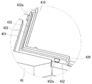
- the water droplet discharge port 453o of each guide groove 453 is provided so as to face between a waterproof wall portion 432 and an inner wall portion 433 of the lower case 41 described later (an enlarged view of FIG. 5). Therefore, water droplets flowing through each guide groove 453 fall between the waterproof wall portion 432 and the inner wall portion 433 and are discharged.
- the cross-sectional shape of the guide groove 453 can be selected as appropriate. here.
- the cross-sectional shape of the guide groove 453 is a semicircular shape (an enlarged view of the cross section of FIGS. 4B to 4B).
- the width of the guide groove 453 is preferably a width at which capillary action occurs. Due to the capillary phenomenon in which the guide groove 453 is regarded as a capillary, water droplets existing in the substrate facing region 451 can be easily guided to the outer region 452 along the guide groove 453. As the width of the guide groove 453 is narrower, the effect of capillary action can be obtained. However, it is preferable that the width of the guide groove 453 is not excessively narrow.
- the depth of the guide groove 453 can be appropriately selected according to the location where the guide groove 453 is formed. When formed on the end face of the rib 454 as in this example, the depth of the guide groove 453 may be uniform in the longitudinal direction.
- -Rib Rib 454 reinforces ceiling part 45.
- the rib 454 is used in a part of the guide groove 453 where it is formed. The greater the number of ribs 454, the higher the strength of the ceiling 45.
- the rib 454 may be provided from the substrate facing region 451 to the outer region 452 in consideration of the use of the rib 454 as a formation location of the guide groove 453. This is because the guide groove 453 can be provided from the substrate facing region 451 to the outer region 452. More specifically, it may be provided from the connector facing region 451a or the extension region 451b of the substrate facing region 451 to the outer region 452.
- the guide groove 453 can be provided from the connector facing region 451a to the outer region 452. Therefore, it is easy to prevent water droplets that have entered the case 40 from falling onto the circuit board 10.
- the longitudinal direction of the rib 454 formed from the connector facing region 451a to the outer region 452 is preferably the left-right direction.
- the guide groove 453 can be provided from the extended region 451b to the outer region 452. Therefore, it is easy to prevent the water droplets in which the water vapor is condensed in the case 40 from dropping onto the circuit board 10.
- the longitudinal direction of the rib 454 formed from the extended region 451b to the outer region 452 may be a left-right direction or an oblique direction.
- ribs 454 that are connected to each other may be provided.
- the guide grooves 453 formed on the end faces of the ribs 454 to be connected may communicate with each other.
- the ceiling portion 45 there are three pairs of horizontal ribs 454s (6 pairs in total) juxtaposed in the front-rear direction on each of the front side and the rear side, and four diagonal ribs 454x arranged in a cross shape at substantially the center. And two pairs of connecting ribs 454c that are opposed to each other across the center and are connected to the oblique ribs 454x.
- Each pair of horizontal ribs 454s is provided along the left-right direction and spaced apart from each other on the same straight line.
- the foremost pair of horizontal ribs 454s is formed from the vicinity of the left and right ends of the connector facing region 451a to the outer regions 452 on the left and right sides.
- the remaining five pairs of horizontal ribs 454s are formed from the vicinity of the left and right end portions of the extension region 451b to the outer regions 452 on both the left and right sides.
- a series of lateral guide grooves 453 s are formed on the lower surface of the ceiling portion 45 between each pair of lateral ribs 454 s and on the end surfaces of each pair of lateral ribs 454 s.
- the four diagonal ribs 454x are two along each of one diagonal direction and the other diagonal direction of two intersecting diagonal directions, and are provided at intervals on the same diagonal line.
- the four oblique ribs 454x are formed from the vicinity of the left and right end portions of the extension region 451b to the left and right outer regions 452 so as to intersect both the left and right and front and rear directions.
- a series of oblique guide grooves 453x are formed on the lower surface of the ceiling portion 45 between the two oblique ribs 454x located on the same diagonal line and the end faces of the two oblique ribs 454x.
- Each pair of connecting ribs 454c is provided along the left-right direction and spaced apart from each other on the same straight line. Each pair of connecting ribs 454c is formed from the vicinity of the left and right ends of the extension region 451b to the oblique ribs 454x. A series of connection guide grooves 453c are formed on the lower surface of the ceiling portion 45 between each pair of connection ribs 454c and the end surfaces of each pair of connection ribs 454c.
- Each of the ribs 454 has an inclined shape (triangular shape) whose height increases from the connector facing region 451a or the extended region 451b toward the outer region 452.
- One end (the inlet 453i side) of each rib 454 is provided in the vicinity of the left and right ends of the connector facing region 451a and the extension region 451b. Accordingly, each rib 454 does not hinder the inflow of water droplets into the guide groove 453, and the water droplets can easily flow into the guide groove 453.
- the other end (exhaust port 453 o side) of each rib 454 is provided in the outer region 452.
- the outlet 453o of the guide groove 453 formed on the end face of the rib 454 is provided in the outer region 452. Therefore, it is easy to flow the water droplet to the outer region 452 and to prevent the water droplet from dropping onto the circuit board 10.
- the side wall portion 46 engages with the lower case 41 to integrate the upper cover 44 and the lower case 41. This prevents water from entering the inside of the case 40 from the outside.
- the location where the side wall 46 is formed is a location excluding the central portions on the left and right sides of the periphery of the ceiling 45. That is, the side wall 43 is formed in series on the front periphery of the ceiling 45 and the front periphery on both left and right sides, and is formed in series on the rear periphery on the ceiling 45 and the rear periphery on both sides. ing.
- the side wall portion 46 is inserted into an insertion groove 431 (FIGS. 2, 5, and 6) formed on the upper surface of the lower case 41.
- the side wall portion 46 includes an upper concave portion 460, a protruding portion 461, and an engagement hole 462.
- the upper recessed part 460 forms the opening part 48 by which the connector part 20 is arrange
- the upper concave portion 460 is formed at a location corresponding to the lower concave portion 430 and a central portion of the side wall portion 46 on the front side.
- the size of the upper concave portion 460 can be selected as appropriate so that the connector portion 20 can be disposed in the opening 48 formed by the lower concave portion 430 and can be positioned with respect to the case 40 of the connector portion 20.
- the upper concave portion 460 is disposed so that the distal end side of the connector portion 20 is exposed outward.
- the protrusion part 461 is formed in the circumference
- the upper portion 461u of the protruding portion 461 is formed as a flat surface substantially flush with the surface (upper surface) of the ceiling portion 45.
- the engagement hole 462 engages with the engagement protrusion 432a of the lower case 41 (waterproof wall part 432). By this engagement, the insertion state of the side wall portion 46 into the insertion groove 431 is maintained, whereby the upper cover 44 and the lower case 41 are fixed.
- the positions where the engagement holes 462 are formed are provided at appropriate positions in the circumferential direction of the side wall portion 46, and here, the front side wall portion 46 and the left and right side wall portions 46 are provided.
- Examples of the material of the upper cover 44 include synthetic resins such as polypropylene (PP) resin and polyamide (PA) resin.
- the lower case 41 accommodates the circuit board 10, the connector part 20, and a bus bar 60 (described later) inside (FIG. 2).
- the lower case 41 is composed of a bottom portion 42 and a side wall portion 43 erected shallowly from the periphery of the bottom portion 42, and has a box shape having an opening on the opposite side (upper side) from the bottom portion 42.
- a storage portion 410 that stores the circuit board 10, the connector portion 20, and the bus bar 60 is formed at a location surrounded by the bottom portion 42 and the side wall portion 43.
- the bottom part 42 and the side wall part 43 are not integrally molded, but are independent members, and are integrated by a fixing member such as a screw 42b (FIG. 5).
- the bottom part 42 and the side wall part 43 may be integrally molded.
- the shape of the bottom portion 42 is a flat plate shape larger than the circuit board 10 and the bus bar 60.
- the bottom portion 42 is formed with an insertion hole (not shown) through which a screw 42 b integrated with the side wall portion 43 is inserted.
- the bottom portion 42 is configured by a heat sink that dissipates heat of the electronic component mounted on the circuit board 10.
- a metal plate such as aluminum can be used.
- the side wall portion 43 forms a storage portion 410 that stores the circuit board 10 and the bus bar 60 together with the bottom portion 42 (FIG. 2).
- the shape of the side wall portion 43 is a substantially rectangular frame that is continuous over the entire circumference of the bottom portion 42, and the side wall portion 43 surrounds four sides of the outer periphery of the circuit board 10 including the connector portion 20.
- the side wall portion 43 includes a lower concave portion 430 formed on the upper surface thereof, an insertion groove 431, a waterproof wall portion 432, an inner wall portion 433, a base portion 434, and a step portion 435 (FIG. 5) formed on the lower surface thereof. Have.
- the lower recessed part 430 forms the opening part 48 (FIG. 1) by which the connector part 20 is arrange
- the formation part of the lower side recessed part 430 is a part corresponding to the upper side recessed part 460, and is a center part of the side wall part 43 of the front.
- the size of the lower concave portion 430 can be appropriately selected as the connector portion 20 can be disposed in the opening 48 formed by the upper concave portion 460 and can be positioned with respect to the case 40 of the connector portion 20.
- the side wall part 46 of the upper cover 44 is inserted (FIG. 2, FIG. 6).
- the formation location (shape viewed from above) of the insertion groove 431 can be appropriately selected according to the location (shape viewed from the bottom surface) of the side wall portion 46 of the upper cover 44.
- the insertion groove 431 is formed at a location excluding the left and right central portions on the upper surface of the side wall portion 43.
- the insertion grooves 431 are formed in the left and right corners of the front side wall 43 and the left and right regions on the rear side.
- the shape of the front insertion groove 431 in plan view is L-shaped, and the shape of the rear insertion groove 431 in plan view is I-shaped.
- the width and depth of the insertion groove 431 can be appropriately selected according to the thickness of the side wall portion 46 of the upper cover 44 and the insertion amount.
- the waterproof wall part 432 is formed in the outer periphery of the accommodating part 410, and prevents permeation of the water into the accommodating part 410 from the exterior of the case 40 (FIG. 2, FIG. 6).
- the waterproof wall portion 432 forms a side surface of the insertion groove 431 and is provided between the side wall portion 46 of the upper cover 44 and the storage portion 410 when the upper cover 44 is inserted into the insertion groove 431. It contacts with the inner surface of the side wall 46 of 44.
- the location where the waterproof wall 432 is formed is the same as that of the insertion groove 431, and is the left and right corners of the front side wall 43 and the left and right regions on the rear side.
- the shape of the front waterproof wall 432 in plan view is L-shaped, and the shape of the rear waterproof wall 432 in plan view is I-shaped.
- the waterproof wall portion 432 includes an engagement protrusion 432a and a drainage portion (not shown).
- the engagement protrusion 432a engages with the engagement hole 462 of the side wall portion 46 of the upper cover 44 inserted into the insertion groove 431 (FIGS. 2 and 6). By this engagement, the upper cover 44 and the lower case 41 are fixed.
- the formation position of the engagement protrusion 423 is a position corresponding to the engagement hole 462, provided at an appropriate position in the circumferential direction of the side wall 43, and provided on the front waterproof wall 432 and the left and right waterproof wall 432. .
- the drainage part discharges water droplets discharged between the inner wall part 433 and the waterproof wall part 432.
- the inner wall part 433 prevents the water droplet discharged
- the inner wall portion 433 is formed between the waterproof wall portion 432 and the storage portion 410 with a space from the waterproof wall portion 432.
- the inner wall portion 433 forms an edge of the storage portion 410.
- the location where the inner wall 433 is formed is the same as that of the waterproof wall 432 and is a region extending from the left and right corners of the front side wall 43 and from the left corner to the right corner on the rear side.
- the shape of the front inner wall portion 433 in plan view is L-shaped, and the shape of the rear inner wall portion 433 in plan view is [letter shape.
- the base part 434 has a terminal fixing
- the base part 434 is formed on the upper surface of the central part on both the left and right sides.
- the extended portion 60 c of the bus bar 60 is placed on the base portion 434.
- the bottom part 42 is engage
- the step portion 435 is formed on the inner peripheral edge portion of the lower surface of the side wall portion 43.
- the stepped portion 435 is formed with a screw hole (not shown) for fixing the screw 42b integrated with the bottom portion 42.
- the material of the lower case 41 is, for example, a synthetic resin such as PP resin or PA resin, similar to the upper cover 44.
- the bus bar 60 constitutes a power circuit.
- the bus bar 60 is connected to a power source or an electrical load.
- the bus bar 60 includes a central portion and extending portions 60c that extend stepwise on the left and right sides thereof.
- a front portion of the central portion of the bus bar 60 is located below the connector portion 20 and is interposed between the lower surface of the circuit board 10 and the upper surface of the bottom portion 42.
- the central portion and the extending portion 60c are integrally formed.
- the central portion is formed in a planar shape and is interposed between the lower surface of the circuit board 10 and the upper surface of the bottom portion 42.
- the extending portion 60 c is disposed on the upper surface of the base portion 434 of the lower case 41.
- the extending portion 60c is formed to be bent in a step shape, and is continuous on both sides of the central portion.
- the extended portion 60c is a portion for electrically connecting an external device, and a connection terminal of an electric wire (wire harness) (not shown) is electrically connected thereto.
- a terminal insertion hole 60h through which the male screw portion 80 is inserted is formed in the extended portion 60c.
- the male screw part 80 fixed to the terminal fixing part of the lower case 41 is inserted into the terminal insertion hole 60h.
- a wire harness (not shown) is attached to the male screw portion 80.
- the bus bar 60 and the wire harness are electrically connected via the male screw portion 80. Examples of the material of the bus bar 60 include a conductive metal, and specifically copper or a copper alloy.
- an adhesive sheet (not shown) interposed between the both 10 and 60 can be used.
- the substrate unit 1A can be suitably used for a substrate unit disposed in a location where waterproofing is not required in an automobile.
- the substrate unit 1A can be suitably used for a large current power control unit such as a DC voltage converter, an AC / DC converter, and a DC / AC inverter.
- a waterproof member such as a waterproof ring is not separately provided, but an inclined rib 454 is formed on the lower surface of the ceiling portion 45 of the upper cover 44, and a guide groove 453 is formed on an end surface thereof.
- the substrate unit 1A can ensure the drip-proof property without separately providing a waterproof member. Therefore, it can be suitably used to ensure waterproofing (drip-proofing) of water drops. Moreover, since it is not necessary to provide a waterproof member separately, the number of parts can be reduced and the assembly workability of the board unit 1A can be improved.
- ⁇ Modification 1 In the substrate unit of the first modification, the ribs are not provided, and the guide groove can be directly formed on the lower surface (back surface) of the ceiling portion instead of the end surface of the rib.
- the depth of the guide groove is preferably shallower from the board facing area (connector facing area or extension area) toward the outer area. If it does so, the water droplet which exists in a board
- the lower surface of the ceiling portion can be an inclined surface (triangular roof type) that is inclined downward from the center in the left-right direction toward both left and right sides.
- the depth of the guide groove and the height of the rib can be made uniform in the longitudinal direction.
Abstract
回路基板と、前記回路基板に実装されるコネクタ部と、前記回路基板を収容するケースと、を備える基板ユニットであって、前記ケースは、上方に開口して前記回路基板を収納する収納部を有する下部ケースと、前記下部ケースの前記収納部を覆う上部カバーと、前記コネクタ部が相手側コネクタ部と嵌合可能に当該ケースの側壁に開口した開口部と、を備え、前記上部カバーは、前記収納部に収納された前記回路基板に対向する基板対向領域と、前記回路基板に対向せず前記基板対向領域よりも外側に位置する外側領域とを有する天井部と、前記基板対向領域から前記外側領域に亘って傾斜して形成され、前記基板対向領域に存在する水滴を前記外側領域に導いて前記回路基板の外側に排出するガイド溝とを備える基板ユニット。
Description
本発明は、基板ユニットに関する。
本出願は、2016年6月8日付の日本国出願の特願2016-114857に基づく優先権を主張し、前記日本国出願に記載された全ての記載内容を援用するものである。
本出願は、2016年6月8日付の日本国出願の特願2016-114857に基づく優先権を主張し、前記日本国出願に記載された全ての記載内容を援用するものである。
特許文献1に記載されるように、電気機器を収容する車載用のケース等では、水の浸入によって収容物である電気機器の故障を防止する防水構造が施される。
本開示に係る基板ユニットは、
回路基板と、
前記回路基板に実装されるコネクタ部と、
前記回路基板を収容するケースと、を備える基板ユニットであって、
前記ケースは、
上方に開口して前記回路基板を収納する収納部を有する下部ケースと、
前記下部ケースの前記収納部を覆う上部カバーと、
前記コネクタ部が相手側コネクタ部と嵌合可能に当該ケースの側壁に開口した開口部と、を備え、
前記上部カバーは、
前記収納部に収納された前記回路基板に対向する基板対向領域と、前記回路基板に対向せず前記基板対向領域よりも外側に位置する外側領域とを有する天井部と、
前記基板対向領域から前記外側領域に亘って傾斜して形成され、前記基板対向領域に存在する水滴を前記外側領域に導いて前記回路基板の外側に排出するガイド溝とを備える。
[本開示が解決しようとする課題]
特許文献1のように、シール部材によってケース内部を密閉等する手法では、製造コストが増加してしまう。
特許文献1のように、シール部材によってケース内部を密閉等する手法では、製造コストが増加してしまう。
そこで、簡易な構成で内部の回路基板への水滴の付着を抑制できる基板ユニットを提供することを目的の一つとする。
[本開示の効果]
本開示の基板ユニットは、簡易な構成で内部の回路基板への水滴の付着を抑制できる。
本開示の基板ユニットは、簡易な構成で内部の回路基板への水滴の付着を抑制できる。
《本発明の実施形態の説明》
最初に本発明の実施態様を列記して説明する。
最初に本発明の実施態様を列記して説明する。
(1)本発明の一態様に係る基板ユニットは、
回路基板と、
前記回路基板に実装されるコネクタ部と、
前記回路基板を収容するケースと、を備える基板ユニットであって、
前記ケースは、
上方に開口して前記回路基板を収納する収納部を有する下部ケースと、
前記下部ケースの前記収納部を覆う上部カバーと、
前記コネクタ部が相手側コネクタ部と嵌合可能に当該ケースの側壁に開口した開口部と、を備え、
前記上部カバーは、
前記収納部に収納された前記回路基板に対向する基板対向領域と、前記回路基板に対向せず前記基板対向領域よりも外側に位置する外側領域とを有する天井部と、
前記基板対向領域から前記外側領域に亘って傾斜して形成され、前記基板対向領域に存在する水滴を前記外側領域に導いて前記回路基板の外側に排出するガイド溝とを備える。
上記の構成によれば、上部カバーがガイド溝を備えるという簡易な構成でケースの内部の回路基板への水滴の付着を抑制できる。ガイド溝により上部カバーの裏面(下面)の基板対向領域に付着した水滴を外側領域に導いて回路基板の外側に排出できて、水滴の回路基板上への落下を防止できるからである。そのため、防水リング等の防水部材を別途設けなくてもよい。それにより、部品点数を削減でき、基板ユニットの組立作業性を向上できる。
基板対向領域に存在する水滴とは、(1)ケースの外部から内部に浸入した水滴(浸入水)と、(2)ケースの内部の水蒸気が結露した水滴(結露水)と、が考えられる。浸入水や結露水は、上部カバーの下面を伝ってガイド溝に入り、外側領域に導かれて回路基板の外側に排出される。
(2)上記基板ユニットの一形態として、前記基板対向領域は、前記コネクタ部に対向するコネクタ対向領域を有し、前記ガイド溝は、前記コネクタ対向領域から前記外側領域に亘って形成されていることが挙げられる。
上記の構成によれば、回路基板への水滴の付着をより効果的に抑制し易い。従来、基板対向領域に存在する水滴は、結露した水滴に比べて、ケースの側壁に形成された開口部から内部に浸入した水滴であることが多い。そのため、開口部(水滴の入口)に近いコネクタ対向領域にガイド溝を形成していることで、浸入した水滴を開口部付近で外側領域に導くことができて、水滴のケースの奥(基板対向領域)への浸入を防止し易いからである。
(3)前記基板対向領域が前記コネクタ対向領域を有する上記基板ユニットの一形態として、以下の形態が挙げられる。
前記天井部は、前記コネクタ対向領域から前記外側領域に亘って形成され、前記コネクタ対向領域から前記外側領域に向かって高さが高くなる傾斜状のリブを有し、
前記ガイド溝は、前記リブの端面に形成されている。
前記天井部は、前記コネクタ対向領域から前記外側領域に亘って形成され、前記コネクタ対向領域から前記外側領域に向かって高さが高くなる傾斜状のリブを有し、
前記ガイド溝は、前記リブの端面に形成されている。
上記の構成によれば、上部カバーの強度を高めつつ、回路基板への水滴の付着を抑制できる。
(4)上記基板ユニットの一形態として、以下の形態が挙げられる。
前記下部ケースは、
前記下部ケースにおける前記収納部の外周に形成されて、前記ケースの外部から前記収納部内への水の浸入を防止する防水壁部と、
前記防水壁部と前記収納部との間で前記防水壁部と間隔を開けて形成される内壁部とを有し、
前記ガイド溝における前記水滴の排出口は、前記防水壁部と前記内壁部との間に臨むように設けられており、
前記防水壁部は、前記内壁部との間に排出された前記水滴を前記防水壁部の外側に排出する排出部を備える。
前記下部ケースは、
前記下部ケースにおける前記収納部の外周に形成されて、前記ケースの外部から前記収納部内への水の浸入を防止する防水壁部と、
前記防水壁部と前記収納部との間で前記防水壁部と間隔を開けて形成される内壁部とを有し、
前記ガイド溝における前記水滴の排出口は、前記防水壁部と前記内壁部との間に臨むように設けられており、
前記防水壁部は、前記内壁部との間に排出された前記水滴を前記防水壁部の外側に排出する排出部を備える。
上記の構成によれば、防水壁部によりケース外部から内部への水滴の浸入を防止できることに加えて、防水壁部の内側の内壁部により、防水壁部と内壁部との間に排出した水滴が流れて回路基板に付着することを抑制できる。また、排出部を備えることで、防水壁部と内壁部との間に排出した水滴をその場に留まらせることなく、防水壁部の外側に排出できる。
《本発明の実施形態の詳細》
本発明の実施形態の詳細を、以下に図面を参照しつつ説明する。図中の同一符号は同一名称物を示す。
本発明の実施形態の詳細を、以下に図面を参照しつつ説明する。図中の同一符号は同一名称物を示す。
《実施形態1》
〔基板ユニット〕
図1から図6を参照して、実施形態1に係る基板ユニット1Aを説明する。基板ユニット1Aは、回路基板10と、回路基板10に実装されるコネクタ部20と、回路基板10及びコネクタ部20を収容するケース40とを備える。ケース40は、下部ケース41と、上部カバー44と、ケース40の側壁に開口した開口部48とを備える。開口部48は、コネクタ部20が相手側コネクタ部(図示略)と嵌合可能に開口している。この基板ユニット1Aの特徴の一つは、上部カバー44がその裏面(下面)に存在する水滴を回路基板10上へ落下させることなく回路基板10の外側へ排出させるガイド溝453を備える点にある。以下、各構成の詳細を説明する。以下の説明では、基板ユニット1Aにおいて、ケース40の下部ケース41側を下側、上部カバー44側を上側とし、ケース40の上下方向と直交する方向であって、コネクタ部20が配置される側を前側、その反対側を後側とする。上下方向及び前後方向の両方向に直交する方向を左右とする。
[回路基板]
回路基板10は、半導体リレー等の電子部品(図示略)やコネクタ部20を実装させる(図2)。回路基板10は、絶縁基板と、その一面に形成されて電子部品が電気的に接続される回路(導体)パターン(図示略)とを有する。この回路基板10は、プリント基板を用いることができる。
回路基板10は、半導体リレー等の電子部品(図示略)やコネクタ部20を実装させる(図2)。回路基板10は、絶縁基板と、その一面に形成されて電子部品が電気的に接続される回路(導体)パターン(図示略)とを有する。この回路基板10は、プリント基板を用いることができる。
[コネクタ部]
コネクタ部20は、基板ユニット1Aに相手側コネクタ部(図示略)を接続する。コネクタ部20は、外方に開口して相手側コネクタ部と嵌合可能なフード状のコネクタハウジング22と、コネクタハウジング22の内部から回路基板10側に延びるコネクタ端子24とを備える(図2)。図1、図2では、説明の便宜上、コネクタハウジング22を柱状で示している。コネクタ端子24は、コネクタハウジング22の開口と反対側の奥壁を貫通して設けられており、一端部がコネクタハウジング22内に配置され、他端部が回路基板10に形成された導電パターンに電気的に接続されている(図2)。この電気的な接続は、半田付けなどの公知の手法により行える。相手側コネクタ部はワイヤーハーネスを介して車載電装品等と接続されている。
コネクタ部20は、基板ユニット1Aに相手側コネクタ部(図示略)を接続する。コネクタ部20は、外方に開口して相手側コネクタ部と嵌合可能なフード状のコネクタハウジング22と、コネクタハウジング22の内部から回路基板10側に延びるコネクタ端子24とを備える(図2)。図1、図2では、説明の便宜上、コネクタハウジング22を柱状で示している。コネクタ端子24は、コネクタハウジング22の開口と反対側の奥壁を貫通して設けられており、一端部がコネクタハウジング22内に配置され、他端部が回路基板10に形成された導電パターンに電気的に接続されている(図2)。この電気的な接続は、半田付けなどの公知の手法により行える。相手側コネクタ部はワイヤーハーネスを介して車載電装品等と接続されている。
[ケース]
ケース40は、内部に回路基板10(図2)及びコネクタ部20を収容する。ケース40は、図1に示すように、下部ケース41と上部カバー44とを組み合わせて構成される。下部ケース41と上部カバー44とを組み合わせて形成されるケース40の側壁には、下部ケース41と上部カバー44とでコネクタ部20が相手側コネクタ部と嵌合可能に開口した開口部48(図1)が形成される。コネクタ部20は、下部ケース41と上部カバー44とで挟み込まれることで、ケース40に対して位置決めされる。
ケース40は、内部に回路基板10(図2)及びコネクタ部20を収容する。ケース40は、図1に示すように、下部ケース41と上部カバー44とを組み合わせて構成される。下部ケース41と上部カバー44とを組み合わせて形成されるケース40の側壁には、下部ケース41と上部カバー44とでコネクタ部20が相手側コネクタ部と嵌合可能に開口した開口部48(図1)が形成される。コネクタ部20は、下部ケース41と上部カバー44とで挟み込まれることで、ケース40に対して位置決めされる。
(上部カバー)
上部カバー44は、下部ケース41の収納部410(図2)を覆う(図1)。上部カバー44は、図2に示すように、ケース40の上面を形成する天井部45と、天井部45の周縁から浅く立設される側壁部46とで構成された一体物である。上部カバー44は、下部ケース41の土台部434を露出させた状態で下部ケース41の上方を覆うような形状に形成されており、外壁の一部に切欠部44cを有する。この切欠部44cにより、下部ケース41に上部カバー44が固定された状態においても、バスバー60(後述)の延設部60cを通すことができる隙間が確保される。この隙間によって、土台部434の上面にバスバー60の延設部60cを載置できる。
上部カバー44は、下部ケース41の収納部410(図2)を覆う(図1)。上部カバー44は、図2に示すように、ケース40の上面を形成する天井部45と、天井部45の周縁から浅く立設される側壁部46とで構成された一体物である。上部カバー44は、下部ケース41の土台部434を露出させた状態で下部ケース41の上方を覆うような形状に形成されており、外壁の一部に切欠部44cを有する。この切欠部44cにより、下部ケース41に上部カバー44が固定された状態においても、バスバー60(後述)の延設部60cを通すことができる隙間が確保される。この隙間によって、土台部434の上面にバスバー60の延設部60cを載置できる。
〈天井部〉
天井部45は、図4に示すように、収納部410に収納された回路基板10に対向する基板対向領域451(二点鎖線の外縁参照)と、回路基板10に対向せず基板対向領域451よりも外側に位置する外側領域452とを有する。ここでは、天井部45の形状は略矩形平板状であり、天井部45の下面は平面状である。天井部45の下面は、左右方向の中央から左右両側に向かって下向きに傾斜する傾斜面(三角屋根型)であってもよい。基板対向領域451の形状は、回路基板10の形状と同じ矩形である。外側領域452の形状は、基板対向領域451の周りを囲む略矩形枠状である。基板対向領域451は、コネクタ部20に対向するコネクタ対向領域451aと、コネクタ対向領域451aのコネクタ部20の軸方向沿いに延長した延長領域451bとを有する。
天井部45は、図4に示すように、収納部410に収納された回路基板10に対向する基板対向領域451(二点鎖線の外縁参照)と、回路基板10に対向せず基板対向領域451よりも外側に位置する外側領域452とを有する。ここでは、天井部45の形状は略矩形平板状であり、天井部45の下面は平面状である。天井部45の下面は、左右方向の中央から左右両側に向かって下向きに傾斜する傾斜面(三角屋根型)であってもよい。基板対向領域451の形状は、回路基板10の形状と同じ矩形である。外側領域452の形状は、基板対向領域451の周りを囲む略矩形枠状である。基板対向領域451は、コネクタ部20に対向するコネクタ対向領域451aと、コネクタ対向領域451aのコネクタ部20の軸方向沿いに延長した延長領域451bとを有する。
天井部45の下面には、その下面に存在する水滴が回路基板10上に落下しないようにするガイド溝453が形成されている(図3,図4)。ここでは、天井部45の下面にリブ454を設け、ガイド溝453は、天井部45の下面とリブ454の端面とに一連に形成されている。
・ガイド溝
ガイド溝453は、基板対向領域451に存在する水滴を外側領域452に導いて回路基板10の外側に排出する。それにより、基板対向領域451に存在する水滴が回路基板10に落下して付着することを抑制できる。基板対向領域451内に存在する水滴とは、(1)ケース40の外部から内部に浸入した水滴(浸入水)と、(2)ケース40の内部の水蒸気が結露した水滴(結露水)と、が考えられる。
ガイド溝453は、基板対向領域451に存在する水滴を外側領域452に導いて回路基板10の外側に排出する。それにより、基板対向領域451に存在する水滴が回路基板10に落下して付着することを抑制できる。基板対向領域451内に存在する水滴とは、(1)ケース40の外部から内部に浸入した水滴(浸入水)と、(2)ケース40の内部の水蒸気が結露した水滴(結露水)と、が考えられる。
(1)浸入水
ケース40にかかった水滴は、ケース40の表面を伝い、側壁部に形成された開口部48側に流れ、開口部48とコネクタ部20との間からケース40の内部に浸入することがある。
ケース40にかかった水滴は、ケース40の表面を伝い、側壁部に形成された開口部48側に流れ、開口部48とコネクタ部20との間からケース40の内部に浸入することがある。
(2)結露水
ケース40の容積が大きいなどケース40内の水蒸気量が多い場合、外気によってケース40が冷やされると、上部カバー44の下面に結露した水滴が付着することがある。
ケース40の容積が大きいなどケース40内の水蒸気量が多い場合、外気によってケース40が冷やされると、上部カバー44の下面に結露した水滴が付着することがある。
浸入水や結露水は、上部カバー44の下面を伝ってガイド溝453に入る。ガイド溝453の水滴は、基板対向領域451から外側領域452に導かれて回路基板10の外側に排出される。
ガイド溝453は、基板対向領域451から外側領域452に亘って傾斜して形成されている。傾斜して形成とは、基板対向領域451から外側領域452に向かって深さが浅くなる場合と、本例のように、基板対向領域451から外側領域452に向かって深さが一様だが、後述する傾斜状のリブ454によりガイド溝453自体が水平方向に対して傾斜する場合とが挙げられる。
ガイド溝453の数は単数でもよいし複数でもよい。いずれの場合でも、ガイド溝453は、少なくとも開口部48の近傍、例えば、基板対向領域451のコネクタ対向領域451aから左右の外側領域452に亘って設けることが好ましい。そうすれば、ケース40内に浸入した水滴の回路基板10への落下を防止し易い。ガイド溝453がケース40における水滴の入口である開口部48に近いところに設けられていることで、浸入した水滴を入口近傍で外側領域452に導くことができて、水滴のケース40の奥への浸入を防止し易いからである。コネクタ対向領域451aから左右の外側領域452に亘って形成するガイド溝453の長手方向の向きは、左右方向に沿っていることが好ましい。そうすれば、ガイド溝453を直線状に形成しつつ、外側領域452までの長さを短くし易いため、水滴が回路基板10上に落下すること無く回路基板10の外側に排出し易い。
ガイド溝453の数を複数とする場合、ガイド溝453は、コネクタ対向領域451aから左右の外側領域452に亘る箇所に加えて、延長領域451bから左右の外側領域452に亘る箇所に設けることが好ましい。そうすれば、ケース40内で水蒸気が結露した水滴の回路基板10への落下を防止し易い。延長領域451bから左右の外側領域452に亘って形成するガイド溝453の長手方向の向きは、適宜選択できる。例えば、ガイド溝453をコネクタ対向領域451aから外側領域452に亘って形成する場合と同様の左右方向や、左右及び前後の両方に交差する斜め方向が挙げられる。ガイド溝453は、結露した水滴が天井部45の下面のどこに存在しても回路基板10への落下を防止し易くするように、天井部45の下面に均等に分散して形成していることが好ましい。
ここでは、天井部45の下面には、前側及び後側のそれぞれで前後方向に並列する3つの横ガイド溝453s(計6つ)と、中央のクロス状の斜めガイド溝453xと、斜めガイド溝453xの交差点を挟んで前後に対向配置される2つの連結ガイド溝453cとが形成されている。
前側の3つの横ガイド溝453sのうち最前の1つの横ガイド溝453sは、左右方向に沿っていて、コネクタ対向領域451aの左右方向の中央から左右の外側領域452に亘って形成されている。残り5つの横ガイド溝453sは、左右方向に沿っていて、延長領域451bの左右方向の中央から左右の外側領域452に亘って形成されている。
斜めガイド溝453xは、左右及び前後の両方向に交差すると共に延長領域451bの略中央から左右の外側領域452に亘って形成されている。斜めガイド溝453xは、中央で連通している。
2つの連結ガイド溝453cは、左右方向に沿うと共に延長領域451bから2つの斜めガイド溝453xに亘って形成されている。2つの連結ガイド溝453cは、2つの斜めガイド溝453xに連通している。
各ガイド溝453の水滴の流入口453iは、コネクタ対向領域451aや延長領域451bに形成されている。各流入口453iはいずれも、ガイド溝453の中央部や交差位置に位置している。各ガイド溝453の水滴の流入口453iの開口端は天井部45の下面と面一である。そのため、水滴をガイド溝に流入させ易い。各ガイド溝453の水滴の排出口453oは、後述する下部ケース41の防水壁部432と内壁部433との間に臨むように設けられている(図5拡大図)。そのため、各ガイド溝453を流れる水滴は、防水壁部432と内壁部433との間に落下して排出される。
ガイド溝453の横断面形状は、適宜選択できる。ここでは。ガイド溝453の横断面形状は、半円状としている(図4(b)-(b)断面の拡大図)。ガイド溝453の幅は、毛細管現象が生じる幅であることが好ましい。ガイド溝453を毛細管とみなした毛細管現象によって、基板対向領域451に存在する水滴をガイド溝453に沿って外側領域452まで導き易い。ガイド溝453の幅は、狭いほど毛細管現象による効果を得られる。但し、ガイド溝453の幅は、過度に狭過ぎないようにすることが好ましい。そうすれば、ガイド溝453での水滴の流通が阻害され難い。ガイド溝453の深さは、ガイド溝453の形成箇所に応じて適宜選択できる。本例のようにリブ454の端面に形成する場合、ガイド溝453の深さは、長手方向に一様とすることが挙げられる。
・リブ
リブ454は、天井部45を補強する。ここでは、リブ454は、ガイド溝453の一部の形成箇所に利用される。リブ454の数は、多いほど天井部45の強度を高められる。
リブ454は、天井部45を補強する。ここでは、リブ454は、ガイド溝453の一部の形成箇所に利用される。リブ454の数は、多いほど天井部45の強度を高められる。
リブ454は、リブ454をガイド溝453の形成箇所に利用することを考慮すると、基板対向領域451から外側領域452に亘って設けることが挙げられる。そうすれば、ガイド溝453を基板対向領域451から外側領域452に亘って設けることができるからである。より具体的には、基板対向領域451のコネクタ対向領域451aや延長領域451bから外側領域452に亘って設けることが挙げられる。
リブ454の形成箇所をコネクタ対向領域451aから外側領域452に亘る箇所とすれば、ガイド溝453をコネクタ対向領域451aから外側領域452に亘って設けることができる。そのため、ケース40内に浸入した水滴の回路基板10への落下を防止し易い。コネクタ対向領域451aから外側領域452に亘って形成するリブ454の長手方向の向きは、左右方向が好ましい。
リブ454の形成箇所を延長領域451bから外側領域452に亘る箇所とすれば、ガイド溝453を延長領域451bから外側領域452に亘って設けることができる。そのため、ケース40内で水蒸気が結露した水滴の回路基板10への落下を防止し易い。延長領域451bから外側領域452に亘って形成するリブ454の長手方向の向きは、左右方向や斜め方向が挙げられる。
リブ454の数を複数とする場合、そのうち、互いに連結するリブ454が設けられていてもよい。その場合、連結するリブ454の端面に形成されるガイド溝453同士は連通していてもよい。
ここでは、天井部45の下面には、前側及び後側のそれぞれで前後方向に並列する3対の横リブ454s(計6対)と、略中央でクロス状に配置される4つの斜めリブ454xと、中央を挟んで前後に対向配置されて斜めリブ454xに連結される2対の連結リブ454cとが形成されている。
各対の横リブ454sは、左右方向に沿っていて、同一直線上で互いに間隔を開けて設けられている。前側の3対の横リブ454sのうち最前の1対の横リブ454sは、コネクタ対向領域451aの左右端部近傍から左右両側の外側領域452に亘って形成されている。残り5対の横リブ454sは、延長領域451bの左右端部近傍から左右両側の外側領域452に亘って形成されている。各対の横リブ454s間における天井部45の下面と、各対の横リブ454sの端面とには、一連の横ガイド溝453sが形成されている。
4つの斜めリブ454xは、交差する2本の対角線方向のうち、一方の対角線方向と他方の対角線方向のそれぞれに2つずつ沿っており、同一対角線上で互いに間隔を開けて設けられている。4つの斜めリブ454xは、左右及び前後の両方向に交差するように延長領域451bの左右端部近傍から左右の外側領域452に亘って形成されている。それぞれの同一対角線上に位置する2つの斜めリブ454x間における天井部45の下面と、その2つの斜めリブ454xの端面とには、一連の斜めガイド溝453xが形成されている。
各対の連結リブ454cは、左右方向に沿っていて、同一直線上で互いに間隔を開けて設けられている。各対の連結リブ454cは、延長領域451bの左右端部近傍から斜めリブ454xに亘って形成されている。各対の連結リブ454c間における天井部45の下面と、各対の連結リブ454cの端面とには、一連の連結ガイド溝453cが形成されている。
各リブ454の形状はいずれも、コネクタ対向領域451aや延長領域451bから外側領域452に向かって高さが高くなる傾斜状(三角状)としている。各リブ454の一端(流入口453i側)は、コネクタ対向領域451aや延長領域451bの左右端部近傍に設けられている。それにより、各リブ454が水滴のガイド溝453への流入を阻害せず、水滴をガイド溝453に流入させ易い。各リブ454の他端(排出口453o側)は、外側領域452に設けられている。それにより、リブ454の端面に形成したガイド溝453の排出口453oを外側領域452に設けられる。そのため、水滴を外側領域452に流れ易くして水滴の回路基板10への落下を防止し易い。
〈側壁部〉
側壁部46は、下部ケース41と係合して上部カバー44と下部ケース41とを一体化する。それにより、ケース40の外部から内部への水の浸入を防止する。側壁部46の形成箇所は、天井部45の周縁における左右両側の中央部分を除いた箇所としている。即ち、側壁部43は、天井部45の前側の周縁と左右両側における前側の周縁とに一連に形成され、天井部45の後側の周縁と左右両側における後側の周縁とに一連に形成されている。側壁部46は、下部ケース41の上面に形成された差込み溝431(図2,図5、図6)に差し込まれる。この側壁部46は、上側凹部460と、突出部461と、係合孔462とを有する。
側壁部46は、下部ケース41と係合して上部カバー44と下部ケース41とを一体化する。それにより、ケース40の外部から内部への水の浸入を防止する。側壁部46の形成箇所は、天井部45の周縁における左右両側の中央部分を除いた箇所としている。即ち、側壁部43は、天井部45の前側の周縁と左右両側における前側の周縁とに一連に形成され、天井部45の後側の周縁と左右両側における後側の周縁とに一連に形成されている。側壁部46は、下部ケース41の上面に形成された差込み溝431(図2,図5、図6)に差し込まれる。この側壁部46は、上側凹部460と、突出部461と、係合孔462とを有する。
・上側凹部
上側凹部460は、下部ケース41の下側凹部430とで内部にコネクタ部20が配置される開口部48を形成する。上側凹部460の形成箇所は、下側凹部430に対応する箇所で、前側の側壁部46の中央部分である。上側凹部460の大きさは、下側凹部430とで形成される開口部48にコネクタ部20が配置可能で、コネクタ部20のケース40に対して位置決め可能な大きさを適宜選択できる。上側凹部460には、コネクタ部20の先端側が外方に露出されるように配置される。
上側凹部460は、下部ケース41の下側凹部430とで内部にコネクタ部20が配置される開口部48を形成する。上側凹部460の形成箇所は、下側凹部430に対応する箇所で、前側の側壁部46の中央部分である。上側凹部460の大きさは、下側凹部430とで形成される開口部48にコネクタ部20が配置可能で、コネクタ部20のケース40に対して位置決め可能な大きさを適宜選択できる。上側凹部460には、コネクタ部20の先端側が外方に露出されるように配置される。
・突出部
突出部461は、コネクタ部20の露出された部分を覆って外方に突出するように上側凹部460の周囲に形成されている。突出部461は、図2に示すように、コネクタ部20の上方及び両側方を囲む上部461u及び両側部461sを有する端面が逆U字状である。突出部461の下端部(両側部461sの下端部)は、開口部48(コネクタ部20)の下縁よりも下方に位置している。突出部461の上部461uは、天井部45の表面(上面)と略面一な平坦面で形成されている。
突出部461は、コネクタ部20の露出された部分を覆って外方に突出するように上側凹部460の周囲に形成されている。突出部461は、図2に示すように、コネクタ部20の上方及び両側方を囲む上部461u及び両側部461sを有する端面が逆U字状である。突出部461の下端部(両側部461sの下端部)は、開口部48(コネクタ部20)の下縁よりも下方に位置している。突出部461の上部461uは、天井部45の表面(上面)と略面一な平坦面で形成されている。
・係合孔
係合孔462は、側壁部46が下部ケース41の差込み溝431に差し込まれた際、下部ケース41(防水壁部432)の係合突起432aに係合する。この係合により、側壁部46の差込み溝431への差込み状態が維持されることで、上部カバー44と下部ケース41とが固定される。係合孔462の形成箇所は、側壁部46の周方向の適所に設けられ、ここでは前側の側壁部46や左右両側の側壁部46としている。
係合孔462は、側壁部46が下部ケース41の差込み溝431に差し込まれた際、下部ケース41(防水壁部432)の係合突起432aに係合する。この係合により、側壁部46の差込み溝431への差込み状態が維持されることで、上部カバー44と下部ケース41とが固定される。係合孔462の形成箇所は、側壁部46の周方向の適所に設けられ、ここでは前側の側壁部46や左右両側の側壁部46としている。
上部カバー44の材質は、例えばポリプロピレン(PP)樹脂やポリアミド(PA)樹脂などの合成樹脂が挙げられる。
(下部ケース)
下部ケース41は、回路基板10、コネクタ部20、及びバスバー60(後述)を内部に収納する(図2)。下部ケース41は、底部42と、底部42の周縁から浅く立設される側壁部43とで構成され、底部42と反対側(上側)が開口した箱状である。底部42と側壁部43とで囲まれた箇所には、回路基板10、コネクタ部20、及びバスバー60を収納する収納部410が形成される。本例では、底部42と側壁部43とは、一体に成形されておらず、それぞれ独立した部材であり、ネジ42b(図5)等の固定部材により一体化されている。底部42と側壁部43とは、一体に成形されていてもよい。
下部ケース41は、回路基板10、コネクタ部20、及びバスバー60(後述)を内部に収納する(図2)。下部ケース41は、底部42と、底部42の周縁から浅く立設される側壁部43とで構成され、底部42と反対側(上側)が開口した箱状である。底部42と側壁部43とで囲まれた箇所には、回路基板10、コネクタ部20、及びバスバー60を収納する収納部410が形成される。本例では、底部42と側壁部43とは、一体に成形されておらず、それぞれ独立した部材であり、ネジ42b(図5)等の固定部材により一体化されている。底部42と側壁部43とは、一体に成形されていてもよい。
〈底部〉
底部42は、回路基板10及び後述するバスバー60が載置される(図2,5)。底部42の形状は、回路基板10及びバスバー60よりも大きな平板状である。底部42には、側壁部43と一体化するネジ42bを挿通する挿通孔(図示略)が形成されている。底部42は、回路基板10に実装された電子部品の熱を放熱するヒートシンクで構成される。ヒートシンクは、例えばアルミニウム等の金属板を用いることができる。
底部42は、回路基板10及び後述するバスバー60が載置される(図2,5)。底部42の形状は、回路基板10及びバスバー60よりも大きな平板状である。底部42には、側壁部43と一体化するネジ42bを挿通する挿通孔(図示略)が形成されている。底部42は、回路基板10に実装された電子部品の熱を放熱するヒートシンクで構成される。ヒートシンクは、例えばアルミニウム等の金属板を用いることができる。
〈側壁部〉
側壁部43は、底部42と共に回路基板10及びバスバー60を収納する収納部410を形成する(図2)。側壁部43の形状は、底部42の全周に亘って連続した略矩形枠体であり、側壁部43は、コネクタ部20を含む回路基板10の外周の四方を囲っている。側壁部43は、その上面に形成される下側凹部430、差込み溝431、防水壁部432、内壁部433、及び土台部434と、その下面に形成される段差部435(図5)とを有する。
側壁部43は、底部42と共に回路基板10及びバスバー60を収納する収納部410を形成する(図2)。側壁部43の形状は、底部42の全周に亘って連続した略矩形枠体であり、側壁部43は、コネクタ部20を含む回路基板10の外周の四方を囲っている。側壁部43は、その上面に形成される下側凹部430、差込み溝431、防水壁部432、内壁部433、及び土台部434と、その下面に形成される段差部435(図5)とを有する。
・下側凹部
下側凹部430は、上部カバー44の上側凹部460とで内部にコネクタ部20が配置される開口部48(図1)を形成する。下側凹部430の形成箇所は、上側凹部460に対応する箇所であり、前方の側壁部43の中央部分である。下側凹部430の大きさは、上側凹部460とで形成される開口部48にコネクタ部20が配置可能で、コネクタ部20のケース40に対して位置決め可能な大きさを適宜選択できる。
下側凹部430は、上部カバー44の上側凹部460とで内部にコネクタ部20が配置される開口部48(図1)を形成する。下側凹部430の形成箇所は、上側凹部460に対応する箇所であり、前方の側壁部43の中央部分である。下側凹部430の大きさは、上側凹部460とで形成される開口部48にコネクタ部20が配置可能で、コネクタ部20のケース40に対して位置決め可能な大きさを適宜選択できる。
・差込み溝
差込み溝431は、上部カバー44の側壁部46が差し込まれる(図2、図6)。差込み溝431の形成箇所(上面視した形状)は、上部カバー44の側壁部46の形成箇所(下面視した形状)に応じて適宜選択できる。差込み溝431の形成箇所は、側壁部43の上面における左右両側の中央部分を除いた箇所としている。差込み溝431は、前側の側壁部43の左右のそれぞれの角部と、後側における左右側の領域とに形成されている。前側の差込み溝431の平面視した形状は、L字状であり、後側の差込み溝431の平面視した形状は、I字状である。差込み溝431の幅と深さとは、上部カバー44の側壁部46の厚みと差し込み量とに応じて適宜選択できる。
差込み溝431は、上部カバー44の側壁部46が差し込まれる(図2、図6)。差込み溝431の形成箇所(上面視した形状)は、上部カバー44の側壁部46の形成箇所(下面視した形状)に応じて適宜選択できる。差込み溝431の形成箇所は、側壁部43の上面における左右両側の中央部分を除いた箇所としている。差込み溝431は、前側の側壁部43の左右のそれぞれの角部と、後側における左右側の領域とに形成されている。前側の差込み溝431の平面視した形状は、L字状であり、後側の差込み溝431の平面視した形状は、I字状である。差込み溝431の幅と深さとは、上部カバー44の側壁部46の厚みと差し込み量とに応じて適宜選択できる。
・防水壁部
防水壁部432は、収納部410の外周に形成されて、ケース40の外部から収納部410内への水の浸入を防止する(図2、図6)。防水壁部432は、差込み溝431の側面を形成し、上部カバー44が差込み溝431に差し込まれた際、上部カバー44の側壁部46と収納部410との間に設けられていて、上部カバー44の側壁部46の内面と接触する。防水壁部432の形成箇所は、差込み溝431と同様であり、前側の側壁部43の左右のそれぞれの角部と、後側における左右側の領域としている。前側の防水壁部432の平面視した形状は、L字状であり、後側の防水壁部432の平面視した形状は、I字状である。防水壁部432は、係合突起432aと、排水部(図示略)とを有する。
防水壁部432は、収納部410の外周に形成されて、ケース40の外部から収納部410内への水の浸入を防止する(図2、図6)。防水壁部432は、差込み溝431の側面を形成し、上部カバー44が差込み溝431に差し込まれた際、上部カバー44の側壁部46と収納部410との間に設けられていて、上部カバー44の側壁部46の内面と接触する。防水壁部432の形成箇所は、差込み溝431と同様であり、前側の側壁部43の左右のそれぞれの角部と、後側における左右側の領域としている。前側の防水壁部432の平面視した形状は、L字状であり、後側の防水壁部432の平面視した形状は、I字状である。防水壁部432は、係合突起432aと、排水部(図示略)とを有する。
係合突起432aは、差込み溝431に差し込まれた上部カバー44の側壁部46の係合孔462と係合する(図2、図6)。この係合により、上部カバー44と下部ケース41とが固定される。係合突起423の形成箇所は、係合孔462に対応する箇所で、側壁部43の周方向の適所に設けられ、前側の防水壁部432や左右両側の防水壁部432に設けられている。
排水部は、内壁部433との間に排出された水滴を防水壁部432の外側に排出する。
・内壁部
内壁部433は、ガイド溝453から排出された水滴が、収納部410内部へ移動することを防止する(図2、図6)。内壁部433は、防水壁部432と収納部410との間で防水壁部432と間隔を開けて形成されている。内壁部433は、収納部410の縁を形成している。内壁部433の形成箇所は、防水壁部432と同様であり、前側の側壁部43の左右のそれぞれの角部と、後側における左側の角部から右側の角部に亘る領域としている。前側の内壁部433の平面視した形状は、L字状であり、後側の内壁部433の平面視した形状は、[字状である。
内壁部433は、ガイド溝453から排出された水滴が、収納部410内部へ移動することを防止する(図2、図6)。内壁部433は、防水壁部432と収納部410との間で防水壁部432と間隔を開けて形成されている。内壁部433は、収納部410の縁を形成している。内壁部433の形成箇所は、防水壁部432と同様であり、前側の側壁部43の左右のそれぞれの角部と、後側における左側の角部から右側の角部に亘る領域としている。前側の内壁部433の平面視した形状は、L字状であり、後側の内壁部433の平面視した形状は、[字状である。
・土台部
土台部434は、雄ねじ部80が固定される端子固定部を有する。土台部434は、左右両側の中央部の上面に形成されている。土台部434には、バスバー60の延設部60cが載置される。
土台部434は、雄ねじ部80が固定される端子固定部を有する。土台部434は、左右両側の中央部の上面に形成されている。土台部434には、バスバー60の延設部60cが載置される。
・段差部
段差部435は、底部42が嵌め込まれる(図5)。段差部435は、側壁部43の下面の内周縁部に形成されている。段差部435には、底部42と一体化するネジ42bを固定するネジ穴(図示略)が形成されている。
段差部435は、底部42が嵌め込まれる(図5)。段差部435は、側壁部43の下面の内周縁部に形成されている。段差部435には、底部42と一体化するネジ42bを固定するネジ穴(図示略)が形成されている。
下部ケース41の材質は、上部カバー44と同様、例えばPP樹脂やPA樹脂などの合成樹脂が挙げられる。
[バスバー]
バスバー60は、電力回路を構成する。バスバー60は、電源や電気的負荷に接続される。バスバー60の数は複数であり、複数のバスバー60は所定のレイアウトで配列されている。バスバー60は、中央部分とその左右に段差状に延びる延設部60cとを備える。バスバー60の中央部分の前方部分は、コネクタ部20の下方に位置し、回路基板10の下面と底部42の上面との間に介在される。これら中央部分と延設部60cとは一体に形成されている。中央部分は、平面状に形成され、回路基板10の下面と底部42の上面との間に介在される。延設部60cは、下部ケース41の土台部434の上面に配置される。延設部60cは、階段状に屈曲して形成され、中央部分の両側にそれぞれ連続している。
バスバー60は、電力回路を構成する。バスバー60は、電源や電気的負荷に接続される。バスバー60の数は複数であり、複数のバスバー60は所定のレイアウトで配列されている。バスバー60は、中央部分とその左右に段差状に延びる延設部60cとを備える。バスバー60の中央部分の前方部分は、コネクタ部20の下方に位置し、回路基板10の下面と底部42の上面との間に介在される。これら中央部分と延設部60cとは一体に形成されている。中央部分は、平面状に形成され、回路基板10の下面と底部42の上面との間に介在される。延設部60cは、下部ケース41の土台部434の上面に配置される。延設部60cは、階段状に屈曲して形成され、中央部分の両側にそれぞれ連続している。
延設部60cは、外部機器を電気的に接続するための部分であり、図示しない電線(ワイヤーハーネス)の接続端子が電気的に接続される。延設部60cには、雄ねじ部80が挿通される端子挿通孔60hが形成されている。端子挿通孔60hには、下部ケース41の端子固定部に固定された雄ねじ部80が挿通される。雄ねじ部80には、ワイヤーハーネス(図示略)が取り付けられる。バスバー60とワイヤーハーネスとは、雄ねじ部80を介して電気的に接続される。バスバー60の材質は、導電性の金属が挙げられ、具体的には銅や銅合金などが挙げられる。回路基板10とバスバー60との固定には、両者10,60間に介在させる接着シート(図示略)を用いることができる。
[用途]
基板ユニット1Aは、自動車における防水を要しない箇所に配置される基板ユニットに好適に利用できる。また基板ユニット1Aは、直流電圧変換器、AC/DC変換器、DC/ACインバータなどの大電流パワー制御ユニットに好適に利用できる。
基板ユニット1Aは、自動車における防水を要しない箇所に配置される基板ユニットに好適に利用できる。また基板ユニット1Aは、直流電圧変換器、AC/DC変換器、DC/ACインバータなどの大電流パワー制御ユニットに好適に利用できる。
〔作用効果〕
実施形態1の基板ユニット1Aは、防水リング等の防水部材を別途設けるのではなく、上部カバー44の天井部45の下面に傾斜状のリブ454を形成し、その端面にガイド溝453を形成するという簡易な構成で、ケース40の内部の回路基板10への水滴の付着を抑制できる。水滴がケース40の外部からその内部に浸入したり、ケース40の内部の水蒸気が結露して水滴が生成されたりして、上部カバー44の天井部45の下面に水滴が付着しても、傾斜状のリブ454の端面に形成されたガイド溝453により水滴を回路基板10の外側に排出できて、水滴の回路基板10上への落下を防止できるからである。そのため、基板ユニット1Aは、防水部材を別途設けなくても防滴性を確保できる。従って、水滴程度の防水(防滴)を確保する場合に好適に利用できる。また、防水部材を別途設けなくてもよいため、部品点数を削減でき、基板ユニット1Aの組立作業性を向上できる。
実施形態1の基板ユニット1Aは、防水リング等の防水部材を別途設けるのではなく、上部カバー44の天井部45の下面に傾斜状のリブ454を形成し、その端面にガイド溝453を形成するという簡易な構成で、ケース40の内部の回路基板10への水滴の付着を抑制できる。水滴がケース40の外部からその内部に浸入したり、ケース40の内部の水蒸気が結露して水滴が生成されたりして、上部カバー44の天井部45の下面に水滴が付着しても、傾斜状のリブ454の端面に形成されたガイド溝453により水滴を回路基板10の外側に排出できて、水滴の回路基板10上への落下を防止できるからである。そのため、基板ユニット1Aは、防水部材を別途設けなくても防滴性を確保できる。従って、水滴程度の防水(防滴)を確保する場合に好適に利用できる。また、防水部材を別途設けなくてもよいため、部品点数を削減でき、基板ユニット1Aの組立作業性を向上できる。
《変形例1》
変形例1の基板ユニットは、リブを設けず、ガイド溝をリブの端面ではなく天井部の下面(裏面)に直接形成できる。その場合、ガイド溝の深さは、基板対向領域(コネクタ対向領域や延長領域)から外側領域に向かって浅くするとよい。そうすれば、基板対向領域に存在する水滴を外側領域に導くことができ、水滴が回路基板に落下して付着することを抑制できる。
変形例1の基板ユニットは、リブを設けず、ガイド溝をリブの端面ではなく天井部の下面(裏面)に直接形成できる。その場合、ガイド溝の深さは、基板対向領域(コネクタ対向領域や延長領域)から外側領域に向かって浅くするとよい。そうすれば、基板対向領域に存在する水滴を外側領域に導くことができ、水滴が回路基板に落下して付着することを抑制できる。
《変形例2》
変形例2の基板ユニットは、天井部の下面を、左右方向の中央から左右両側に向かって下向きに傾斜する傾斜面(三角屋根型)とすることができる。その場合、ガイド溝の深さやリブの高さは、長手方向に一様とすることができる。そうすれば、天井部の下面自体が基板対向領域から外側領域に向かって下向きに傾斜しているため、ガイド溝により基板対向領域に存在する水滴を外側領域に導くことができる。
変形例2の基板ユニットは、天井部の下面を、左右方向の中央から左右両側に向かって下向きに傾斜する傾斜面(三角屋根型)とすることができる。その場合、ガイド溝の深さやリブの高さは、長手方向に一様とすることができる。そうすれば、天井部の下面自体が基板対向領域から外側領域に向かって下向きに傾斜しているため、ガイド溝により基板対向領域に存在する水滴を外側領域に導くことができる。
本発明はこれらの例示に限定されるものではなく、請求の範囲によって示され、請求の範囲と均等の意味および範囲内でのすべての変更が含まれることが意図される。
1A 基板ユニット
10 回路基板
20 コネクタ部
22 コネクタハウジング 24 コネクタ端子
40 ケース
41 下部ケース 410 収納部
42 底部
42b ネジ
43 側壁部
430 下側凹部 431 差込み溝
432 防水壁部 432a 係合突起 433 内壁部
434 土台部 435 段差部
44 上部カバー
44c 切欠部
45 天井部
451 基板対向領域
451a コネクタ対向領域 451b 延長領域
452 外側領域
453 ガイド溝
453s 横ガイド溝 453x 斜めガイド溝
453c 連結ガイド溝
453i 流入口 453o 排出口
454 リブ
454s 横リブ 454x 斜めリブ 454c 連結リブ
46 側壁部
460 上側凹部
461 突出部
461u 上部 461s 側部
462 係合孔
48 開口部
60 バスバー 60c 延設部 60h 端子挿通孔
80 雄ねじ部
Claims (4)
- 回路基板と、
前記回路基板に実装されるコネクタ部と、
前記回路基板を収容するケースと、を備える基板ユニットであって、
前記ケースは、
上方に開口して前記回路基板を収納する収納部を有する下部ケースと、
前記下部ケースの前記収納部を覆う上部カバーと、
前記コネクタ部が相手側コネクタ部と嵌合可能に当該ケースの側壁に開口した開口部と、を備え、
前記上部カバーは、
前記収納部に収納された前記回路基板に対向する基板対向領域と、前記回路基板に対向せず前記基板対向領域よりも外側に位置する外側領域とを有する天井部と、
前記基板対向領域から前記外側領域に亘って傾斜して形成され、前記基板対向領域に存在する水滴を前記外側領域に導いて前記回路基板の外側に排出するガイド溝とを備える基板ユニット。 - 前記基板対向領域は、前記コネクタ部に対向するコネクタ対向領域を有し、
前記ガイド溝は、前記コネクタ対向領域から前記外側領域に亘って形成されている請求項1に記載の基板ユニット。 - 前記天井部は、前記コネクタ対向領域から前記外側領域に亘って形成され、前記コネクタ対向領域から前記外側領域に向かって高さが高くなる傾斜状のリブを有し、
前記ガイド溝は、前記リブの端面に形成されている請求項2に記載の基板ユニット。 - 前記下部ケースは、
前記下部ケースにおける前記収納部の外周に形成されて、前記ケースの外部から前記収納部内への水の浸入を防止する防水壁部と、
前記防水壁部と前記収納部との間で前記防水壁部と間隔を開けて形成される内壁部とを有し、
前記ガイド溝における前記水滴の排出口は、前記防水壁部と前記内壁部との間に臨むように設けられており、
前記防水壁部は、前記内壁部との間に排出された前記水滴を前記防水壁部の外側に排出する排出部を備える請求項1から請求項3のいずれか1項に記載の基板ユニット。
Priority Applications (3)
| Application Number | Priority Date | Filing Date | Title |
|---|---|---|---|
| US16/306,940 US10653019B2 (en) | 2016-06-08 | 2017-06-06 | Substrate unit |
| DE112017002906.6T DE112017002906T5 (de) | 2016-06-08 | 2017-06-06 | Substrateinheit |
| CN201780032848.4A CN109315073B (zh) | 2016-06-08 | 2017-06-06 | 基板单元 |
Applications Claiming Priority (2)
| Application Number | Priority Date | Filing Date | Title |
|---|---|---|---|
| JP2016114857A JP6604519B2 (ja) | 2016-06-08 | 2016-06-08 | 基板ユニット |
| JP2016-114857 | 2016-06-08 |
Publications (1)
| Publication Number | Publication Date |
|---|---|
| WO2017213144A1 true WO2017213144A1 (ja) | 2017-12-14 |
Family
ID=60577849
Family Applications (1)
| Application Number | Title | Priority Date | Filing Date |
|---|---|---|---|
| PCT/JP2017/021002 WO2017213144A1 (ja) | 2016-06-08 | 2017-06-06 | 基板ユニット |
Country Status (5)
| Country | Link |
|---|---|
| US (1) | US10653019B2 (ja) |
| JP (1) | JP6604519B2 (ja) |
| CN (1) | CN109315073B (ja) |
| DE (1) | DE112017002906T5 (ja) |
| WO (1) | WO2017213144A1 (ja) |
Families Citing this family (3)
| Publication number | Priority date | Publication date | Assignee | Title |
|---|---|---|---|---|
| JP6632038B2 (ja) | 2018-01-31 | 2020-01-15 | Necプラットフォームズ株式会社 | 放熱耐水構造 |
| JP2019149520A (ja) | 2018-02-28 | 2019-09-05 | ファナック株式会社 | 電子機器 |
| JP7307669B2 (ja) | 2019-12-16 | 2023-07-12 | 日立Astemo株式会社 | 電力変換装置 |
Citations (8)
| Publication number | Priority date | Publication date | Assignee | Title |
|---|---|---|---|---|
| JP2001118628A (ja) * | 1999-10-21 | 2001-04-27 | Sumitomo Wiring Syst Ltd | コネクタ |
| JP2002335090A (ja) * | 2001-05-07 | 2002-11-22 | Denso Corp | 電子機器 |
| JP2003229678A (ja) * | 2002-01-31 | 2003-08-15 | Denso Corp | 電子制御装置の筐体構造 |
| JP2004096968A (ja) * | 2002-09-04 | 2004-03-25 | Sumitomo Wiring Syst Ltd | 電気接続箱の排水構造 |
| JP2006050814A (ja) * | 2004-08-05 | 2006-02-16 | Auto Network Gijutsu Kenkyusho:Kk | 電気接続箱 |
| JP2006344687A (ja) * | 2005-06-07 | 2006-12-21 | Denso Corp | 電子装置用筐体 |
| JP2011229253A (ja) * | 2010-04-19 | 2011-11-10 | Yazaki Corp | 電気接続箱 |
| WO2016158445A1 (ja) * | 2015-03-27 | 2016-10-06 | 日本電気株式会社 | 電子機器の蓋部材及び電子機器の筐体 |
Family Cites Families (4)
| Publication number | Priority date | Publication date | Assignee | Title |
|---|---|---|---|---|
| DE112011105709T5 (de) * | 2011-10-05 | 2014-08-21 | Autonetworks Technologies, Ltd. | Elektronische Schalteinheit, welche zu einer externen Verbindung fähig ist |
| JP2014175365A (ja) | 2013-03-06 | 2014-09-22 | Aisin Kiko Co Ltd | 基板ケース |
| JP2016114857A (ja) | 2014-12-16 | 2016-06-23 | キヤノン株式会社 | 情報処理装置、その制御方法、プログラム、及び記憶媒体 |
| JP2016186979A (ja) * | 2015-03-27 | 2016-10-27 | 日本電気株式会社 | 電子機器の蓋部材及び電子機器の筐体 |
-
2016
- 2016-06-08 JP JP2016114857A patent/JP6604519B2/ja active Active
-
2017
- 2017-06-06 DE DE112017002906.6T patent/DE112017002906T5/de active Pending
- 2017-06-06 WO PCT/JP2017/021002 patent/WO2017213144A1/ja active Application Filing
- 2017-06-06 CN CN201780032848.4A patent/CN109315073B/zh active Active
- 2017-06-06 US US16/306,940 patent/US10653019B2/en active Active
Patent Citations (8)
| Publication number | Priority date | Publication date | Assignee | Title |
|---|---|---|---|---|
| JP2001118628A (ja) * | 1999-10-21 | 2001-04-27 | Sumitomo Wiring Syst Ltd | コネクタ |
| JP2002335090A (ja) * | 2001-05-07 | 2002-11-22 | Denso Corp | 電子機器 |
| JP2003229678A (ja) * | 2002-01-31 | 2003-08-15 | Denso Corp | 電子制御装置の筐体構造 |
| JP2004096968A (ja) * | 2002-09-04 | 2004-03-25 | Sumitomo Wiring Syst Ltd | 電気接続箱の排水構造 |
| JP2006050814A (ja) * | 2004-08-05 | 2006-02-16 | Auto Network Gijutsu Kenkyusho:Kk | 電気接続箱 |
| JP2006344687A (ja) * | 2005-06-07 | 2006-12-21 | Denso Corp | 電子装置用筐体 |
| JP2011229253A (ja) * | 2010-04-19 | 2011-11-10 | Yazaki Corp | 電気接続箱 |
| WO2016158445A1 (ja) * | 2015-03-27 | 2016-10-06 | 日本電気株式会社 | 電子機器の蓋部材及び電子機器の筐体 |
Also Published As
| Publication number | Publication date |
|---|---|
| CN109315073B (zh) | 2020-08-25 |
| CN109315073A (zh) | 2019-02-05 |
| DE112017002906T5 (de) | 2019-02-21 |
| JP6604519B2 (ja) | 2019-11-13 |
| JP2017220597A (ja) | 2017-12-14 |
| US10653019B2 (en) | 2020-05-12 |
| US20190150303A1 (en) | 2019-05-16 |
Similar Documents
| Publication | Publication Date | Title |
|---|---|---|
| JP5173596B2 (ja) | 電気接続箱 | |
| JP4304207B2 (ja) | 電力分配装置 | |
| US8389856B2 (en) | Waterproof structure of electrical junction box | |
| JP4657025B2 (ja) | 電気接続箱 | |
| US7931478B2 (en) | Electrical junction box | |
| JP5051465B2 (ja) | 電気接続箱 | |
| WO2017213144A1 (ja) | 基板ユニット | |
| CN109196965B (zh) | 基板单元 | |
| US7270552B2 (en) | Electric connection box | |
| JP6604477B2 (ja) | 基板ユニット | |
| US20090137135A1 (en) | Connector for board and electrical junction box | |
| JP6318085B2 (ja) | 電気接続箱の排水構造 | |
| JP2000102138A (ja) | 電気接続箱 | |
| JP2009290943A (ja) | 電気接続箱 | |
| JP2007259652A (ja) | 電気接続箱 | |
| JP5471793B2 (ja) | 電気接続箱 | |
| JP2000092652A (ja) | 電気接続箱 | |
| JP4374296B2 (ja) | 電気接続箱 | |
| JP2001102768A (ja) | 電気接続箱 | |
| US11147173B2 (en) | Electronic device | |
| JP2006050814A (ja) | 電気接続箱 | |
| JP5898545B2 (ja) | 電子装置 | |
| JP2007110852A (ja) | 電気接続箱 | |
| JP6287888B2 (ja) | ケース | |
| JP5733164B2 (ja) | 回路ユニット |
Legal Events
| Date | Code | Title | Description |
|---|---|---|---|
| 121 | Ep: the epo has been informed by wipo that ep was designated in this application |
Ref document number: 17810319 Country of ref document: EP Kind code of ref document: A1 |
|
| 122 | Ep: pct application non-entry in european phase |
Ref document number: 17810319 Country of ref document: EP Kind code of ref document: A1 |