WO2017209145A1 - エクスパンションタンク - Google Patents
エクスパンションタンク Download PDFInfo
- Publication number
- WO2017209145A1 WO2017209145A1 PCT/JP2017/020150 JP2017020150W WO2017209145A1 WO 2017209145 A1 WO2017209145 A1 WO 2017209145A1 JP 2017020150 W JP2017020150 W JP 2017020150W WO 2017209145 A1 WO2017209145 A1 WO 2017209145A1
- Authority
- WO
- WIPO (PCT)
- Prior art keywords
- water
- tank
- separation chamber
- cooling
- cooling water
- Prior art date
- Legal status (The legal status is an assumption and is not a legal conclusion. Google has not performed a legal analysis and makes no representation as to the accuracy of the status listed.)
- Ceased
Links
Images




Classifications
-
- B—PERFORMING OPERATIONS; TRANSPORTING
- B60—VEHICLES IN GENERAL
- B60K—ARRANGEMENT OR MOUNTING OF PROPULSION UNITS OR OF TRANSMISSIONS IN VEHICLES; ARRANGEMENT OR MOUNTING OF PLURAL DIVERSE PRIME-MOVERS IN VEHICLES; AUXILIARY DRIVES FOR VEHICLES; INSTRUMENTATION OR DASHBOARDS FOR VEHICLES; ARRANGEMENTS IN CONNECTION WITH COOLING, AIR INTAKE, GAS EXHAUST OR FUEL SUPPLY OF PROPULSION UNITS IN VEHICLES
- B60K11/00—Arrangement in connection with cooling of propulsion units
- B60K11/02—Arrangement in connection with cooling of propulsion units with liquid cooling
- B60K11/04—Arrangement or mounting of radiators, radiator shutters, or radiator blinds
-
- E—FIXED CONSTRUCTIONS
- E02—HYDRAULIC ENGINEERING; FOUNDATIONS; SOIL SHIFTING
- E02F—DREDGING; SOIL-SHIFTING
- E02F9/00—Component parts of dredgers or soil-shifting machines, not restricted to one of the kinds covered by groups E02F3/00 - E02F7/00
-
- F—MECHANICAL ENGINEERING; LIGHTING; HEATING; WEAPONS; BLASTING
- F01—MACHINES OR ENGINES IN GENERAL; ENGINE PLANTS IN GENERAL; STEAM ENGINES
- F01P—COOLING OF MACHINES OR ENGINES IN GENERAL; COOLING OF INTERNAL-COMBUSTION ENGINES
- F01P11/00—Component parts, details, or accessories not provided for in, or of interest apart from, groups F01P1/00 - F01P9/00
-
- F—MECHANICAL ENGINEERING; LIGHTING; HEATING; WEAPONS; BLASTING
- F01—MACHINES OR ENGINES IN GENERAL; ENGINE PLANTS IN GENERAL; STEAM ENGINES
- F01P—COOLING OF MACHINES OR ENGINES IN GENERAL; COOLING OF INTERNAL-COMBUSTION ENGINES
- F01P3/00—Liquid cooling
- F01P3/20—Cooling circuits not specific to a single part of engine or machine
-
- F—MECHANICAL ENGINEERING; LIGHTING; HEATING; WEAPONS; BLASTING
- F01—MACHINES OR ENGINES IN GENERAL; ENGINE PLANTS IN GENERAL; STEAM ENGINES
- F01P—COOLING OF MACHINES OR ENGINES IN GENERAL; COOLING OF INTERNAL-COMBUSTION ENGINES
- F01P5/00—Pumping cooling-air or liquid coolants
- F01P5/02—Pumping cooling-air; Arrangements of cooling-air pumps, e.g. fans or blowers
- F01P5/06—Guiding or ducting air to, or from, ducted fans
Definitions
- the present invention relates to an expansion tank connected to an engine cooling device.
- a construction machine such as a hydraulic excavator is equipped with a water cooling type cooling device equipped with a radiator or the like for cooling a prime mover such as an engine.
- the cooling device may be connected to a hermetic expansion tank (also referred to as a reserve tank) having an air chamber inside as an air spring corresponding to a volume change due to thermal expansion of the cooling water (patent) References 1, 2 etc.).
- the air chamber return method when injecting water into the cooling device, such as when assembling a new car or changing the cooling water, air from the cooling device flows in as the cooling water is supplied from the expansion tank to the cooling device via the outflow port. It is discharged to the expansion tank through the port. This is because the inflow port opens into the air chamber. The air led from the cooling device to the air chamber of the expansion tank is discharged from the expansion tank through the water inlet.
- water injection is easy, but while the engine is running, the cooling water that has flowed into the expansion tank jets into the air chamber and then falls to the water surface. There is a problem in gas-liquid separation performance because air is easily mixed. Further, when the engine is stopped and the circulation of the cooling water is stopped, a part of the air flows back from the expansion tank to the cooling device, and the engine cooling effect immediately after the engine is stopped may be reduced.
- the cooling device that circulates the cooling device while the engine is operating is guided under the surface of the expansion tank, and thus has excellent gas-liquid separation performance.
- the cooling device when water is poured into the cooling device, if the inflow port is submerged, the air in the cooling device is not smoothly guided to the expansion tank, and there is a problem that the efficiency of the water filling operation is reduced.
- the present invention has been made in view of the above-described problems of the prior art, and an object of the present invention is to provide an expansion tank that can achieve both water injection workability and gas-liquid separation performance for an engine cooling device.
- the present invention is a sealed expansion tank that is connected to a cooling device of a prime mover and separates air from cooling water that circulates through the cooling device.
- an expansion tank having a communication hole below a water level reference line that is a set water level and extending vertically and partitioning the inside of the tank body into a plurality of separation chambers, the cooling device to the tank body An inlet port connected to the inlet separation chamber which is one of the plurality of separation chambers at a position below the water level reference line, and the tank body from the tank body An outlet of cooling water to the cooling device, which is in contact with an outlet separation chamber that is a separation chamber other than the inlet separation chamber among the plurality of separation chambers, at a position below the water level reference line.
- (First embodiment) 1. Construction Machine
- a crawler type hydraulic excavator as a construction machine
- the expansion tank according to the present invention can be widely applied in addition to a crawler type hydraulic excavator as long as it is a construction machine including a prime mover such as an engine that is an internal combustion engine that burns fuel to generate power and a cooling device for the engine.
- a prime mover such as an engine that is an internal combustion engine that burns fuel to generate power
- a cooling device for the engine for example, construction machines with different uses such as cranes, wheel loaders, tractors, construction machines other than crawler type such as wheel type, or engine driven types such as electric excavators that drive hydraulic pumps with electric motors that are other examples of prime movers. It can also be applied to construction machines.
- FIG. 1 is a side view showing an appearance of a hydraulic excavator that is an example of a construction machine to which an expansion tank according to a first embodiment of the present invention is applied. Thereafter, the front side (left side in FIG. 1), the rear side (right side), the left side (front side in the direction orthogonal to the paper surface), and the right side (back side in the direction orthogonal to the paper surface) of the operator seated in the driver's seat are in front of the hydraulic excavator 1. , Rear, left, and right, respectively, simply referred to as front, rear, left, and right.
- a hydraulic excavator 1 shown in FIG. 1 includes a traveling body 2, a revolving body 4 that is turnably mounted on the traveling body 2, and a working device 5 that performs excavation work of earth and sand.
- the traveling body 2 includes left and right crawler frames 21, left and right crawler belts 22 on an endless track wound around the left and right crawler frames 21, and left and right traveling hydraulic motors 23 that respectively drive the left and right crawler belts 22.
- the turning body 4 includes a turning frame 6, a cab 7, a counterweight 8, and the like.
- the turning frame 6 is a base frame of the turning body 4, and is provided on the traveling body 2 via the turning device 3 so as to be turnable.
- the cab 7 is a driver's cab provided on the left side of the front part of the revolving frame 6, and has a driver's seat 71 on which an operator sits, an operation lever (not shown) for operating each hydraulic actuator, and the like.
- the counterweight 8 is a weight for balancing the weight with the work device 5, and is attached to the rear end portion of the turning frame 6.
- a machine room 25 defined by an exterior cover 11 and the like is disposed at the rear part of the revolving frame 6 (between the cab 7 and the counterweight 8).
- each hydraulic actuator is driven by a hydraulic pump driven by the engine 9 and the hydraulic pump.
- a control valve for controlling the flow of the pressure oil supplied to is provided.
- the exterior cover 11 has an inflow port 13 formed of a plurality of vertically long holes, and is sucked into the machine room 25 through the inflow port 13.
- the working device 5 includes a boom 5A, an arm 5B, a bucket 5C, a boom cylinder 5D, an arm cylinder 5E, and a bucket cylinder 5F.
- the boom 5 ⁇ / b> A is connected to the right side of the front portion of the revolving frame 6 so as to be rotatable up and down.
- the arm 5B is pivotably attached to the tip of the boom 5A
- the bucket 5C is pivotally attached to the tip of the arm 5B.
- Both ends of the boom cylinder 5D are connected to the boom 5A and the turning frame 6, and the boom 5A swings up and down as the boom cylinder 5D expands and contracts.
- Both ends of the arm cylinder 5E are connected to the arm 5B and the boom 5A, and the arm 5B swings back and forth as the arm cylinder 5E expands and contracts.
- Both ends of the bucket cylinder 5F are connected to a link connected to the bucket 5C and the arm 5B, and the bucket 5C rotates as the bucket cylinder 5F expands and contracts.
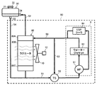
- FIG. 2 is a schematic diagram of an engine cooling device provided in the hydraulic excavator of FIG.
- the engine cooling device 90 (hereinafter referred to as the cooling device 90) includes a radiator 80, a water pump 91, a thermostat 92, a water jacket 93, an EGR cooler 94, and the like.
- thick arrows connecting elements indicate the flow path and flow direction of the cooling water.
- the radiator 80 includes an upper tank 80A, a radiator core 80B, and a lower tank 80C.
- the upper tank 80A is connected to the engine 9 via an upper line 50 (such as a hose), and cooling water from the engine 9 flows into the upper tank 80A.
- the radiator core 80B is connected to the lower side of the upper tank 80A, and has a plurality of cooling water thin tubes and radiating fins (not shown). Cooling air and heat generated by the cooling fan 10 from the cooling water flowing into the upper tank 80A. Replace and cool.
- the lower tank 80C is connected to the lower side of the radiator core 80B and connected to the engine 9 via the lower line 51 (hose or the like), and the cooling water cooled by the radiator core 80B is supplied to the engine 9 via the lower line 51. To do.
- the cooling fan 10 is configured to be driven by the electric motor 12, but may be configured to be driven by the engine 9.
- the water pump 91 is driven by the power of the engine 9, sucks the cooling water supplied to the engine 9, discharges it toward the water jacket 93 and the EGR cooler 94, and circulates the cooling water in the circuit of the cooling device 90.
- the water jacket 93 is a water passage provided around a cylinder (not shown) of the engine 9, and the cooling water sent from the water pump 91 mainly exchanges heat with the engine 9 when passing through the water jacket 91. Cooling.
- the EGR cooler 94 is provided in an EGR pipe (not shown), and cools a part of engine exhaust (hereinafter referred to as EGR gas) passing through the EGR pipe by heat exchange with cooling water.
- EGR gas a part of engine exhaust
- the cooled EGR gas is mixed with intake air and introduced into the cylinder.
- the EGR cooler 94 and the cooling system associated therewith can be omitted.
- the thermostat 92 is a temperature type valve device provided in a bypass line 53 that connects the upper line 50 and the lower line 51.
- the thermostat 92 is provided in the bypass line 53 according to the cooling water temperature so that the temperature of the engine 9 falls within a predetermined range. Adjust the flow rate.
- the thermostat 92 includes, for example, a thermometer and a drive unit. When the coolant temperature measured by the thermometer is equal to or higher than the set temperature, the valve opening is lowered by the drive unit, and when the temperature is lower than the set temperature, the valve opening is raised. . If the valve opening decreases, the amount of cooling water supplied to the engine 9 via the radiator 80 increases, and if the valve opening increases, the amount of cooling water supplied to the engine 9 bypassing the radiator 80 increases.
- Expansion tank The expansion tank 30 (hereinafter referred to as tank 30) is a hermetic reserve tank having a gas-liquid separation function and an air spring function, and loops to the cooling device 90 via an air vent pipe 52 and a makeup pipe 54. Connected.
- the gas-liquid separation function of the tank 30 contributes to taking in the cooling water circulating through the cooling device 90 and removing air from the cooling water.
- the air spring function uses an internal air chamber and contributes to absorbing fluctuations in the internal pressure of the cooling device 90 due to a volume change due to thermal expansion of the cooling water.
- cooling refers to pouring cooling water into the cooling device 90 via the tank 30 for replacement or replenishment of cooling water
- water supply refers to the supply of cooling water from the tank 30 to the cooling device 90.
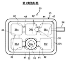
- FIG. 3 is a side view of the tank 30, and FIG. 4 is a plan view.
- the tank 30 includes a tank body 35, a partition wall 42, an inflow port 34, an outflow port 33, a water inlet 31, and a backflow prevention device 38. Next, each element will be explained.
- the tank body 35 is an outer wall of the tank 30 formed of a translucent resin or the like so that the water level can be visually confirmed.
- the shape is not particularly limited, but in this embodiment, the tank body 35 is a rectangular parallelepiped shape with corners having an R shape. is there.
- the tank body 35 employs an upper and lower divided structure including an upper housing 35A and a lower housing 35B.
- the upper housing 35A and the lower housing 35B are integrally formed together with the partition wall 42, and are connected to each other by a flange 35C.
- the boundary between the upper housing 35A and the lower housing 35B is a water level reference line 43 that is a set water level of the tank body 35 when the excavator 1 is in a horizontal posture (for example, when it is in contact with a horizontal plane). It is set as.
- the water level reference line 43 can be arbitrarily set depending on the size of the tank 30, etc., and can be displayed together with a notation that the water level is set if necessary, or two lines indicating the upper limit and the lower limit of the set water level. It is good also as an aspect which displays this line.
- the water level reference line 43 is useful for appropriate management of the water level in the tank 30 by a maintenance worker, and contributes to maintaining an appropriate gas-liquid separation function and air spring function of the tank 30.
- the tank 30 is arranged so that the water level reference line 43 is higher than the uppermost part of the cooling device 90 (strictly, the uppermost part of the cooling water circuit inside the cooling device 90).
- the partition wall 42 is a partition wall extending vertically, and partitions the inside of the tank body 35 into a plurality of (four in this embodiment) separation chambers 36a to 36f adjacent to the front, rear, left and right.
- Each partition 42 includes an upper half part integrally molded with the upper housing 35A and a lower half part integrally molded with the lower housing 35B, and the upper half part is joined by joining the upper housing 35A and the lower housing 35B.
- the lower half is connected.
- the partition wall 42 separating the separation chambers 36 a and 36 b has a cooling water communication hole 44 at a position below the water level reference line 43, and the separation chambers 36 a and 36 b have cooling water below the water level reference line 43.
- the communication holes 44 communicate with each other.
- the separation chambers 36b and 36c, the separation chambers 36c and 36d, the separation chambers 36d and 36e, and the separation chambers 36e and 36f are in communication with each other through the cooling water communication holes 44 below the water level reference line 43, respectively.
- the partition wall 42 that separates the separation chambers 36b and 36e and the partition wall 42 that separates the separation chambers 36a and 36f are not provided with the communication holes 44 for cooling water.
- the separation chambers 36a to 36f communicate with at least one adjacent separation chamber via an air communication hole 45 formed at a position above the water level reference line 43 of the partition wall 42.
- the cooling water inside the tank 30 moves in the order of the separation chamber 36a ⁇ the separation chamber 36b ⁇ the separation chamber 36c ⁇ the separation chamber 36d ⁇ the separation chamber 36f.
- the cooling water inside the tank 30 is gradually moved to the separation chambers 36a to 36f sequentially, and gas-liquid separation is promoted.
- the space (air chamber) above the water level reference line 43 of each separation chamber 36a to 36f performs the above-described air spring function.
- the inflow port 34 is an inlet of cooling water from the cooling device 90 to the tank body 35.
- the upper tank 80A of the radiator 80 and the inflow port 34 are connected via the air vent pipe 52, but the engine 9 or the upper line 50 and the inflow port 34 are connected by the air vent pipe 52. It may be configured to.
- the inflow port 34 is connected to the side surface of the tank body 35 in the present embodiment, and is one of the plurality of separation chambers 36a to 36f at a position below the water level reference line 43, in the present embodiment, the separation chamber. Open to 36a.
- the separation chamber 36a to which the inflow port 34 is connected may be referred to as an “inlet separation chamber 36a”.
- the installation position of the inflow port 34 with respect to the inlet separation chamber 36a can be changed, it is desirable that the inflow port 34 is flooded after water injection regardless of the scene. Therefore, when the excavator 1 is in a horizontal posture and the amount of cooling water whose water level coincides with the water level reference line 43 is stored in the tank body 35, the hydraulic excavator 1 is inclined regardless of which direction the hydraulic excavator 1 tilts. In the range where the inclination angle of the shovel 1 does not exceed a preset maximum allowable inclination angle, it is desirable to install the inflow port 34 at a position where it is not exposed above the coolant level in the tank body 35.
- the maximum allowable inclination angle is, for example, an angle set in advance with respect to the excavator 1 in a range in which oil does not flow out from the oil pan of the engine 9.
- the outflow port 33 is an outlet for cooling water from the tank body 35 to the cooling device 90.
- the lower line 51 and the inflow port 34 are connected via the makeup pipe 54.
- the lower tank 80C of the radiator 80 and the outflow port 33 are connected by the makeup pipe 54.
- the outflow port 33 is one of the plurality of separation chambers 36a to 36f and opens into a separation chamber other than the inlet separation chamber 36a, in this embodiment, the separation chamber 36e at a position below the water level reference line 43. ing.
- the separation chamber 36e to which the outflow port 33 is connected may be referred to as “exit separation chamber 36e”.
- the water injection port 31 is an opening for pouring water into the tank 30, and is a separation level chamber 43a of the separation chambers 36a to 36f other than the inlet separation chamber 36a, in this embodiment, the water level reference line 43 of the outlet separation chamber 36e. It is provided at a position above (for example, the top surface).
- a cap 32 with a pressure valve capable of adjusting the air pressure inside the tank 30 is attached to the water injection port 31 except during water injection, and the pressure in the tank 30 is appropriately maintained.
- the tank 30 is sealed by tightening the cap 32 after water injection.
- the pressure valve may be provided in the upper part of the tank 30 instead of the cap 32.
- the backflow prevention device 38 is a device that prevents the backflow of the cooling water from the inflow port 34 to the outflow port 33 in the inlet separation chamber 36a, and a check valve can be typically used.
- the backflow prevention device 38 is provided in the cooling water communication hole 44 provided in the partition wall 42 that partitions the inlet separation chamber 36a (separates the separation chambers 36a and 36b).
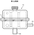
- FIG. 5 is a side view of an expansion tank according to a first comparative example
- FIG. 6 is a side view of an expansion tank according to a second comparative example.
- an expansion tank T1 (hereinafter referred to as tank T1) having a configuration in which the backflow prevention device 38 is omitted from the tank 30 according to the first embodiment is illustrated as a first comparative example.
- an expansion tank T2 (hereinafter referred to as tank T2) having a configuration in which the inflow port P1 of the tank T1 according to the first comparative example is moved to the air chamber (position higher than the water level reference line L) is referred to as the second comparative example.
- tank T2 having a configuration in which the inflow port P1 of the tank T1 according to the first comparative example is moved to the air chamber (position higher than the water level reference line L) is referred to as the second comparative example.
- the first comparative example is a so-called water chamber return type expansion tank that introduces cooling water from a position lower than the water level reference line L
- the second comparative example is a so-called air chamber that introduces cooling water from a position higher than the water level reference line L. It is an example of the expansion tank of a return system.
- an air chamber return type tank T2 as shown in FIG. 6 is generally used in many cases.
- the air chamber return type tank T2 also has the following three problems.
- the first problem is insufficient gas-liquid separation performance. While the engine is operating, the cooling water is pumped from the engine cooling device to the tank T2. In the tank T2, the cooling water is ejected into the air in the tank T2, and the air once enters the cooling water. In addition, it is inevitable that air enters the stored water when the cooling water that has fallen from the air chamber falls to the water surface. Therefore, the gas-liquid separation performance of the air chamber return type tank T2 is lower than that of the water chamber return type tank T1.
- the second problem is the backflow of air to the engine cooling device when the engine is stopped. While the engine is operating, the air vent pipe connected to the inflow port P1 by the water pump is filled with the cooling water, and the cooling water is introduced into the tank T2. However, when the engine stops, the circulation of the cooling water also stops, and the air in the tank T2 flows back to the engine cooling device via the inflow port P1 due to the head difference. At this time, if the vehicle body on which the tank T2 is mounted is inclined and the water level reference line L of the tank T2 is lower than the last part of the engine or radiator, the air flowing backward from the inflow port P1 further flows back to the radiator or engine. Can do. In a cooling water circuit that cools a high-temperature part such as an engine, cooling can be delayed by replacing the cooling water with the backflowed air.
- the third problem is insufficient protection performance of the tank T2.
- the high-temperature water inside the engine cooling device is discharged to the air chamber via the inflow port P1, so that the hot water may directly hit the wall surface of the separation chamber.
- the tank T2 is made of, for example, resin, direct contact with high-temperature water can be a factor that promotes deterioration of the structural material of the tank T2.
- the outlet separation chamber 36e provided with the outflow port 33 is a different separation chamber from the inlet separation chamber 36a provided with the inflow port 34, and cooling the partition wall 42 separating the inlet separation chamber 36a and the adjacent separation chamber 36b.
- a backflow prevention device 38 is provided in the water communication hole 44.
- the water injection port 31 is provided in a separation chamber (in this embodiment, the outlet separation chamber 36e) other than the inlet separation chamber 36a. Therefore, the movement of the cooling water introduced into the inlet separation chamber 36a during the operation of the engine 9 to the separation chamber 36b and the supply of water to the cooling device 90 are allowed, but the inlet separation chambers from the other separation chambers 36b to 36f are allowed at the time of water injection.
- the backflow of the cooling water to 36 a is prevented by the backflow prevention device 38. Since the inflow of the cooling water poured into the tank 30 into the inlet separation chamber 36a is hindered by the backflow prevention device 38, the flooding of the inflow port 34 can be suppressed, and the water injection workability is also good. Therefore, the workability of water injection for the cooling device 90 and the gas-liquid separation performance can be made compatible. Since the cooling efficiency of the cooling device 90 can be improved by improving the gas-liquid separation performance, it is particularly meaningful for a construction machine having a large prime mover and generating a large amount of heat.
- the inflow port 34 is disposed at a position where it is not exposed to the air chamber unless there is an amount of cooling water that satisfies the water level reference line 43 unless the inclination angle of the excavator 1 exceeds the maximum allowable inclination angle. It is preferable. By arranging the inflow port 34 at such a position, even when the engine 9 is stopped, the inflow port 34 is not exposed from the water surface, so that the air in the air chamber can be prevented from flowing back to the cooling device 90. Therefore, it can suppress that the cooling water which retains in high temperature parts, such as the engine 9, is substituted with air, and can suppress the cooling stagnation of a high temperature member. This point is particularly significant for construction machines that operate on slopes.
- the tank body 35 has a vertically divided structure, the partition wall 42, the cooling water communication hole 44, the air communication hole 45, and the like inside the tank body 35 can be easily formed. Also, the backflow prevention device 38 can be easily assembled before joining the upper housing 35A and the lower housing 35B. Therefore, the manufacture of the tank 30 can be facilitated.
- FIG. 7 is a side view of an expansion tank according to a second embodiment of the present invention
- FIG. 8 is a plan view
- FIGS. 7 and 8 correspond to FIGS. 3 and 4 of the first embodiment, respectively. 7 and 8, the same elements as those in the previous drawings are denoted by the same reference numerals, and description thereof is omitted.
- the expansion tank 30A (hereinafter referred to as tank 30A) shown in FIGS. 7 and 8 is different from the tank 30 according to the first embodiment in that an inlet port 34 is provided on the bottom surface of the inlet separation chamber 36a. It is a point (open).
- the inflow port 34 is provided at the center of the bottom surface of the inlet separation chamber 36a (for example, the centers of the inlet separation chamber 36a and the inflow port 34 coincide) is illustrated.
- the inflow port 34 may be installed at a position near the center O of the tank body 35.
- the other configuration of the tank 30A is the same as that of the tank 30 of the first embodiment, including the connection mode and arrangement with the cooling device 90, the construction machine to be applied, the operation, and the like.
- the inflow port is arranged on the bottom surface of the expansion tank together with the outflow port, so that it becomes impossible to inject water when the inflow port is flooded. Therefore, even in the water chamber return method, the inflow port is often arranged as high as possible with respect to the outflow port in order to ensure the water injection performance.
- the backflow prevention device 38 is provided, so that the flooding of the inflow port 34 due to the poured cooling water can be suppressed. Can be provided.
- the inflow port 34 When the inflow port 34 is provided on the bottom surface of the tank body 35 as in the present embodiment, the maximum inclination angle is not exceeded compared to the configuration in which the inflow port 34 is provided on the side surface of the tank body 35 as in the first embodiment. It is easy to adopt a configuration in which the opening of the inflow port 34 is maintained under the surface of the cooling water under conditions. In particular, the position of the center of the inlet separation chamber 36a or the position closer to the center O of the tank body 35 than that is easily satisfied. Therefore, it is more advantageous in obtaining the effect of suppressing the cooling stagnation of the high temperature member.
- the configuration in which the cooling water in the inlet separation chamber 36a moves only to the separation chamber 36b has been exemplified.
- a cooling water communication hole 44 is added to the partition wall 42 separating the separation chambers 36a and 36f, and the inlet The cooling water may be moved from the separation chamber 36a to a plurality of separation chambers.
- the backflow prevention device 38 since it is necessary to install the backflow prevention device 38 in all of the plurality of cooling water communication holes 44 that connect the inlet separation chamber 36a and the adjacent separation chamber, the backflow prevention device 38 depends on the connection structure of the separation chamber. Multiple can be installed.
- the number of separation chambers communicating with the inlet separation chamber 36a and the cooling water communication hole 44 is limited to a single number as in the first and second embodiments, the number of the backflow prevention devices 38 is sufficient, and the structure is simplified. There is a merit of low cost.
- the backflow prevention device 38 may be provided in the inflow port 34 instead. good. Needless to say, in this case, the backflow prevention device 38 allows the flow of the cooling water flowing into the inlet separation chamber 36a from the cooling device 90, and the flow of the cooling water from the inflow port 34 to the cooling device 90 is blocked. It is a configuration.
- the number of separation chambers in the tanks 30 and 30A is not limited and may be plural. Therefore, the required number of partition walls 42 is at least one.
- cooling water communication holes 44 facing in the same direction on the same axis as shown in FIGS. 3, 4, 7, and 8. In some cases, the center axis is shifted. The same applies to the air communication hole 45. Further, it is not always necessary to make the sizes of the cooling water communication holes 44 uniform, and they may be uneven. The same applies to the air communication hole 45.
- the backflow prevention device 38 is not necessarily limited to the check valve, and a float valve or the like can be applied.
- the valve is closed when the water level is lower than the set water level set lower than the water level reference line 43 to suppress the flooding of the inflow port 34 and the valve is opened when the water level is higher than the set water level. It can be configured to allow water supply to the cooling device 90.
- SYMBOLS 1 Hydraulic excavator (construction machine), 9 ... Engine (motor), 30, 30A ... Expansion tank, 31 ... Water injection port, 33 ... Outflow port, 34 ... Inflow port, 35 ... Tank main body, 36a-36f ... Separation chamber, 36a ... inlet separation chamber, 36e ... outlet separation chamber, 38 ... backflow prevention device, 42 ... partition wall, 43 ... water level reference line, 44 ... cooling water communication hole (communication hole), 90 ... engine cooling device (cooling device), O ... Center of tank body
Landscapes
- Engineering & Computer Science (AREA)
- Chemical & Material Sciences (AREA)
- Combustion & Propulsion (AREA)
- Mechanical Engineering (AREA)
- General Engineering & Computer Science (AREA)
- Transportation (AREA)
- Mining & Mineral Resources (AREA)
- Civil Engineering (AREA)
- Structural Engineering (AREA)
- Component Parts Of Construction Machinery (AREA)
- Cooling, Air Intake And Gas Exhaust, And Fuel Tank Arrangements In Propulsion Units (AREA)
Abstract
エンジン冷却装置に接続され、冷却装置を循環する冷却水から空気を分離する密閉型のエクスパンションタンク30において、タンク本体35と、水位基準線43よりも下側に連通穴44を有しタンク本体35の内部を複数の分離室36a~36fに仕切る複数の隔壁42と、分離室36aに対して水位基準線43よりも下側の位置で接続された流入ポート34と、分離室36a以外の分離室36eに対して水位基準線43よりも下側の位置で接続された流出ポート33と、分離室36a以外の分離室に設けられた注水口31と、分離室36aを区画する隔壁42の連通穴44に設けた逆流防止装置38を備えたことを特徴とする。
Description
本発明は、エンジン冷却装置に接続するエクスパンションタンクに関する。
一般に、油圧ショベル等の建設機械には、エンジン等の原動機を冷却するためにラジエータ等を備えた水冷式の冷却装置が搭載されている。冷却装置には、冷却水の熱膨張による体積変化に対応する空気バネとして内部に空気室を持つ密閉式のエクスパンションタンク(リザーブタンクと称されることもある)が接続される場合がある(特許文献1,2等参照)。
近年、流路長の増加等を理由に冷却装置内に空気が溜まり易くなってきており、冷却効率の低下抑制のために冷却装置のエア抜きの重要性が高まってきている。そこで、冷却装置を流れる冷却水を流入ポートからエクスパンションタンクに導いて冷却水から空気を分離して空気室に収集(気液分離)し、空気を分離した冷却水を流出ポートから冷却装置に戻すシステムが検討されている。エクスパンションタンクには、流入ポートを水位基準線より高位置に配置する方式(気室戻し方式)と水位基準線より低位置に配置する方式(水室戻し方式)がある。
気室戻し方式では、新車組立時や冷却水交換時等、冷却装置に注水する際、流出ポートを介してエクスパンションタンクから冷却装置に冷却水が供給されるのに伴って冷却装置の空気が流入ポートを介してエクスパンションタンクに排出される。流入ポートが空気室に開口しているからである。冷却装置からエクスパンションタンクの空気室に導かれた空気は、注水口を介してエクスパンションタンクから排出される。ただ気室戻し方式の場合、注水が容易である一方で、エンジン稼働中はエクスパンションタンクに流入した冷却水が空気室に噴出した後で水面に落下するので、噴出及び落下の際に冷却水に空気が混入し易く気液分離性能に課題がある。また、エンジンが停止して冷却水の循環が止まると、エクスパンションタンクから一部の空気が冷却装置に逆流し、エンジン停止直後のエンジン冷却効果が低下する場合がある。
他方、流入ポートが水位基準線よりも低位置にある水室戻し方式では、エンジン稼働中に冷却装置を循環する冷却装置はエクスパンションタンクの水面下に導かれるため気液分離性能に優れる。しかしその一方で、冷却装置に注水する際には、流入ポートが冠水してしまうと冷却装置内の空気がエクスパンションタンクに円滑に導かれず、注水作業の効率が低下する課題がある。
本発明は上述した従来技術の課題に鑑みなされたもので、エンジン冷却装置に対する注水の作業性と気液分離性能を両立させることができるエクスパンションタンクを提供することを目的とする。
上記目的を達成するために、本発明は、原動機の冷却装置に接続され、前記冷却装置を循環する冷却水から空気を分離する密閉型のエクスパンションタンクであって、タンク本体と、前記タンク本体の設定水位である水位基準線よりも下側に連通穴を有すると共に上下に延び、前記タンク本体の内部を複数の分離室に仕切る隔壁とを備えたエクスパンションタンクにおいて、前記冷却装置から前記タンク本体への冷却水の入口であって、前記複数の分離室のうちの1つである入口分離室に対して前記水位基準線よりも下側の位置で接続された流入ポートと、前記タンク本体から前記冷却装置への冷却水の出口であって、前記複数の分離室のうちの前記入口分離室以外の分離室である出口分離室に対して前記水位基準線よりも下側の位置で接続された流出ポートと、前記複数の分離室のうちの前記入口分離室以外の分離室に設けられた注水口と、前記入口分離室を区画する前記隔壁の前記連通穴又は前記流入ポートに設けられ、前記流入ポートから前記流出ポートに向かう冷却水の流れの逆流を防止する逆流防止装置とを備えたことを特徴とする。
本発明によれば、エンジン冷却装置に対する注水の作業性と気液分離性能を両立させることができる。
以下に図面を用いて本発明の実施の形態を説明する。
(第1実施形態)
1.建設機械
本実施形態では、建設機械としてクローラ式の油圧ショベルに本発明に係るエクスパンションタンクを適用した例を説明する。但し、燃料を燃焼させて動力を発生させる内燃機関であるエンジン等の原動機とその冷却装置を備える建設機械であれば、本発明に係るエクスパンションタンクはクローラ式の油圧ショベル以外にも広く適用できる。例えばクレーン、ホイールローダ、トラクタ等の用途の異なる建設機械、ホイール式等のクローラ式以外の建設機械、或いは原動機の他の例である電動機で油圧ポンプを駆動する電動ショベル等のエンジン駆動式以外の建設機械にも適用可能である。
1.建設機械
本実施形態では、建設機械としてクローラ式の油圧ショベルに本発明に係るエクスパンションタンクを適用した例を説明する。但し、燃料を燃焼させて動力を発生させる内燃機関であるエンジン等の原動機とその冷却装置を備える建設機械であれば、本発明に係るエクスパンションタンクはクローラ式の油圧ショベル以外にも広く適用できる。例えばクレーン、ホイールローダ、トラクタ等の用途の異なる建設機械、ホイール式等のクローラ式以外の建設機械、或いは原動機の他の例である電動機で油圧ポンプを駆動する電動ショベル等のエンジン駆動式以外の建設機械にも適用可能である。
図1は本発明の第1実施形態に係るエクスパンションタンクを適用する建設機械の一例である油圧ショベルの外観を表す側面図である。以降、運転席に着いたオペレータの前側(図1中の左側)、後側(同右側)、左側(同紙面直交方向手前側)、右側(同紙面直交方向奥側)を油圧ショベル1の前、後、左、右とし、それぞれ単に前側、後側、左側、右側と記載する。
図1に示した油圧ショベル1は、走行体2、この走行体2上に旋回可能に搭載された旋回体4、土砂の掘削作業等を行う作業装置5を備えている。
走行体2は、左右のクローラフレーム21、左右のクローラフレーム21にそれぞれ掛け回された無限軌道の左右の履帯22、左右の履帯22をそれぞれ駆動する左右の走行用油圧モータ23を有する。
旋回体4は、旋回フレーム6、キャブ7、カウンタウェイト8等を備えている。旋回フレーム6は旋回体4のベースフレームであり、旋回装置3を介して走行体2上に旋回可能に設けられている。キャブ7は旋回フレーム6の前部左側に設けた運転室であり、オペレータが座る運転席71、各油圧アクチュエータを操作するための操作レバー(図示せず)等を内部に有している。カウンタウェイト8は作業装置5との重量バランスをとるための錘であり、旋回フレーム6の後端部に取り付けられている。旋回フレーム6の後部(キャブ7とカウンタウェイト8の間)には、外装カバー11等で区画された機械室25が配置されている。機械室25には、原動機としてのエンジン9(図2参照)やエンジン冷却装置90(図2参照)の他、図示していないが、エンジン9で駆動される油圧ポンプ、油圧ポンプから各油圧アクチュエータに供給される圧油の流れを制御する制御弁等が備えられている。外装カバー11には縦長の複数の孔からなる流入口13が形成されており、流入口13を介して機械室25に吸気されるようになっている。
作業装置5は、ブーム5A、アーム5B、バケット5C、ブームシリンダ5D、アームシリンダ5E、バケットシリンダ5Fを備えている。ブーム5Aは、旋回フレーム6の前部右側に上下に回動可能に連結されている。アーム5Bはブーム5Aの先端に回動可能に、バケット5Cはアーム5Bの先端に、それぞれ回動可能に取り付けられている。ブームシリンダ5Dの両端はブーム5Aと旋回フレーム6とに連結され、ブームシリンダ5Dの伸縮に伴ってブーム5Aが上下に揺動する。アームシリンダ5Eの両端はアーム5Bとブーム5Aとに連結され、アームシリンダ5Eの伸縮に伴ってアーム5Bが前後に揺動する。バケットシリンダ5Fの両端はバケット5Cに連結されたリンクとアーム5Bとに連結され、バケットシリンダ5Fの伸縮に伴ってバケット5Cが回動する。
2.エンジン冷却装置
図2は図1の油圧ショベルに備えられたエンジン冷却装置の模式図である。エンジン冷却装置90(以下、冷却装置90と記載する)は、ラジエータ80、ウォーターポンプ91、サーモスタット92、ウォータージャケット93、EGRクーラ94等を備えている。図2中で要素間を繋ぐ太線矢印は、冷却水の流路及び流れ方向を示している。
図2は図1の油圧ショベルに備えられたエンジン冷却装置の模式図である。エンジン冷却装置90(以下、冷却装置90と記載する)は、ラジエータ80、ウォーターポンプ91、サーモスタット92、ウォータージャケット93、EGRクーラ94等を備えている。図2中で要素間を繋ぐ太線矢印は、冷却水の流路及び流れ方向を示している。
ラジエータ80は、アッパータンク80A、ラジエータコア80B、ロアータンク80Cを備えている。アッパータンク80Aはアッパーライン50(ホース等)を介してエンジン9に接続され、エンジン9からの冷却水がアッパータンク80Aに流入するようになっている。ラジエータコア80Bはアッパータンク80Aの下側に接続され、図示しない複数の冷却水細管及び放熱フィンを有しており、アッパータンク80Aに流入した冷却水を冷却ファン10で発生させた冷却風と熱交換して冷却する。ロアータンク80Cはラジエータコア80Bの下側に接続されると共にロアーライン51(ホース等)を介してエンジン9に接続され、ロアーライン51を介してラジエータコア80Bで冷却された冷却水をエンジン9に供給する。冷却ファン10は電動機12で駆動される構成であるが、エンジン9で駆動する構成とすることもある。
ウォーターポンプ91は、エンジン9の動力により駆動され、エンジン9に供給される冷却水を吸い込んでウォータージャケット93及びEGRクーラ94に向けて吐出し、冷却装置90の回路内で冷却水を循環させる。
ウォータージャケット93はエンジン9のシリンダ(不図示)の周囲に設けられた水路であり、ウォーターポンプ91から送り出された冷却水は主にここを通過する際にエンジン9と熱交換してエンジン9を冷却する。
EGRクーラ94は、EGR管路(不図示)に設けられ、このEGR配管を通過するエンジン排気の一部(以下、EGRガスという)を冷却水と熱交換させて冷却する。冷却されたEGRガスは、吸入空気と混合されてシリンダ内に導入される。EGRクーラ94及びこれに関連する冷却系は省略可能である。
サーモスタット92はアッパーライン50とロアーライン51を接続するバイパスライン53に設けられた温度式の弁装置であり、エンジン9の温度が所定範囲に収まるように、冷却水温度に応じてバイパスライン53に流す流量を調整する。サーモスタット92は例えば温度計と駆動部を備えており、温度計で計測された冷却水温度が設定温度以上の場合に駆動部により弁開度を下げ、設定温度未満の場合に弁開度を上げる。弁開度が下がればラジエータ80を経由してエンジン9に供給される冷却水量が増え、弁開度が上がればラジエータ80をバイパスしてエンジン9に供給される冷却水量が増える。
3.エクスパンションタンク
エクスパンションタンク30(以下、タンク30と記載する)は気液分離機能と空気バネ機能を有する密閉式のリザーブタンクであり、エア抜き配管52及びメイクアップ配管54を介して冷却装置90にループ状に接続されている。このタンク30の気液分離機能は、冷却装置90を循環する冷却水を取り込んで冷却水から空気を取り除くことに寄与する。空気バネ機能は、内部の空気室を利用したものであり、冷却水の熱膨張による体積変化に伴う冷却装置90の内部圧力の変動を吸収することに寄与する。以降、冷却水の交換又は補充のためにタンク30を介して冷却装置90に冷却水を注ぎ入れることを「注水」、タンク30から冷却装置90に冷却水が供給されることを「給水」と言い分ける。
エクスパンションタンク30(以下、タンク30と記載する)は気液分離機能と空気バネ機能を有する密閉式のリザーブタンクであり、エア抜き配管52及びメイクアップ配管54を介して冷却装置90にループ状に接続されている。このタンク30の気液分離機能は、冷却装置90を循環する冷却水を取り込んで冷却水から空気を取り除くことに寄与する。空気バネ機能は、内部の空気室を利用したものであり、冷却水の熱膨張による体積変化に伴う冷却装置90の内部圧力の変動を吸収することに寄与する。以降、冷却水の交換又は補充のためにタンク30を介して冷却装置90に冷却水を注ぎ入れることを「注水」、タンク30から冷却装置90に冷却水が供給されることを「給水」と言い分ける。
図3はタンク30の側面図、図4は平面図である。図3及び図4に示したように、タンク30は、タンク本体35、隔壁42、流入ポート34、流出ポート33、注水口31、逆流防止装置38を備えている。続いて各要素について説明してゆく。
・タンク本体
タンク本体35は水位が目視確認できるように半透明の樹脂等で形成されたタンク30の外壁であり、形状は特に限定されないが本実施形態では角部をR形状とした直方体状である。タンク本体35は隔壁42を形成するために上側ハウジング35A及び下側ハウジング35Bからなる上下二分割構造が採用されている。上側ハウジング35A及び下側ハウジング35Bは、それぞれ隔壁42と共に一体に成形され、フランジ35Cで互いに繋ぎ合せてある。本実施形態では、上側ハウジング35Aと下側ハウジング35Bの境界部を、油圧ショベル1が水平姿勢であるとき(例えば水平面に接地しているとき)のタンク本体35の設定水位である水位基準線43として設定している。但し、水位基準線43はタンク30の大きさ等によって任意に設定可能であり、必要であれば設定水位である旨の表記と共に表示することもできるし、設定水位の上限及び下限を示す2本のラインを表示する態様としても良い。水位基準線43は保守作業者によるタンク30内の水位の適切な管理に役立ち、タンク30の適切な気液分離機能と空気バネ機能の維持に寄与する。
タンク本体35は水位が目視確認できるように半透明の樹脂等で形成されたタンク30の外壁であり、形状は特に限定されないが本実施形態では角部をR形状とした直方体状である。タンク本体35は隔壁42を形成するために上側ハウジング35A及び下側ハウジング35Bからなる上下二分割構造が採用されている。上側ハウジング35A及び下側ハウジング35Bは、それぞれ隔壁42と共に一体に成形され、フランジ35Cで互いに繋ぎ合せてある。本実施形態では、上側ハウジング35Aと下側ハウジング35Bの境界部を、油圧ショベル1が水平姿勢であるとき(例えば水平面に接地しているとき)のタンク本体35の設定水位である水位基準線43として設定している。但し、水位基準線43はタンク30の大きさ等によって任意に設定可能であり、必要であれば設定水位である旨の表記と共に表示することもできるし、設定水位の上限及び下限を示す2本のラインを表示する態様としても良い。水位基準線43は保守作業者によるタンク30内の水位の適切な管理に役立ち、タンク30の適切な気液分離機能と空気バネ機能の維持に寄与する。
なお、水位基準線43が冷却装置90の最上部(厳密には冷却装置90の内部の冷却水回路の最上部)よりも高くなるように、タンク30は配置してある。
・隔壁
隔壁42は上下に延びる仕切り壁であり、前後左右に隣り合う四角柱状の複数(本実施形態では6個)の分離室36a~36fにタンク本体35の内部を仕切っている。各隔壁42は、上側ハウジング35Aと一体成型された上半部、及び下側ハウジング35Bと一体成型された下半部からなり、上側ハウジング35Aと下側ハウジング35Bを接合することで上半部と下半部が繋がる構造である。分離室36a,36bを隔てる隔壁42は水位基準線43よりも下側の位置に冷却水用連通穴44を有しており、分離室36a,36bは水位基準線43よりも下側で冷却水用連通穴44によって互いに連通している。分離室36b,36c、分離室36c,36d、分離室36d,36e、分離室36e,36fも同様にそれぞれ水位基準線43よりも下側で冷却水用連通穴44によって互いに連通している。分離室36b,36eを隔てる隔壁42、及び分離室36a,36fを隔てる隔壁42には冷却水用連通穴44は設けられていない。また、分離室36a~36fは、隔壁42の水位基準線43よりも上側の位置に形成された空気用連通穴45を介して隣り合う少なくとも1つの分離室と連通している。
隔壁42は上下に延びる仕切り壁であり、前後左右に隣り合う四角柱状の複数(本実施形態では6個)の分離室36a~36fにタンク本体35の内部を仕切っている。各隔壁42は、上側ハウジング35Aと一体成型された上半部、及び下側ハウジング35Bと一体成型された下半部からなり、上側ハウジング35Aと下側ハウジング35Bを接合することで上半部と下半部が繋がる構造である。分離室36a,36bを隔てる隔壁42は水位基準線43よりも下側の位置に冷却水用連通穴44を有しており、分離室36a,36bは水位基準線43よりも下側で冷却水用連通穴44によって互いに連通している。分離室36b,36c、分離室36c,36d、分離室36d,36e、分離室36e,36fも同様にそれぞれ水位基準線43よりも下側で冷却水用連通穴44によって互いに連通している。分離室36b,36eを隔てる隔壁42、及び分離室36a,36fを隔てる隔壁42には冷却水用連通穴44は設けられていない。また、分離室36a~36fは、隔壁42の水位基準線43よりも上側の位置に形成された空気用連通穴45を介して隣り合う少なくとも1つの分離室と連通している。
本実施形態では、タンク30の内部の冷却水は、分離室36a→分離室36b→分離室36c→分離室36d→分離室36fと移動していく。このようにタンク本体35の内部を複数の分離室36a~36fに仕切ることで、タンク30の内部の冷却水を分離室36a~36fに順次緩やかに移動させ、気液分離が促進される。また、各分離室36a~36fの水位基準線43よりも上側の空間(空気室)が前述した空気バネ機能を果たす。
・流入ポート
流入ポート34は、冷却装置90からタンク本体35への冷却水の入口である。本実施形態ではエア抜き配管52を介してラジエータ80のアッパータンク80Aと流入ポート34とを接続した例を挙げているが、エア抜き配管52でエンジン9又はアッパーライン50と流入ポート34とを接続する構成とすることもある。流入ポート34は、本実施形態ではタンク本体35の側面に接続しており、水位基準線43よりも下側の位置で複数の分離室36a~36fのうちの1つ、本実施形態では分離室36aに開口している。以降、流入ポート34が接続された分離室36aを「入口分離室36a」と記載する場合がある。
流入ポート34は、冷却装置90からタンク本体35への冷却水の入口である。本実施形態ではエア抜き配管52を介してラジエータ80のアッパータンク80Aと流入ポート34とを接続した例を挙げているが、エア抜き配管52でエンジン9又はアッパーライン50と流入ポート34とを接続する構成とすることもある。流入ポート34は、本実施形態ではタンク本体35の側面に接続しており、水位基準線43よりも下側の位置で複数の分離室36a~36fのうちの1つ、本実施形態では分離室36aに開口している。以降、流入ポート34が接続された分離室36aを「入口分離室36a」と記載する場合がある。
また、入口分離室36aに対する流入ポート34の設置位置は変更可能であるが、注水後は場面によらず流入ポート34が冠水していることが望ましい。そこで、油圧ショベル1が水平姿勢である場合に水位基準線43に水位が一致する冷却水量がタンク本体35に貯留されているとしたとき、油圧ショベル1がいずれの方向に傾斜しても、油圧ショベル1の傾斜角度が予め設定された最大許容傾斜角を超えない範囲ではタンク本体35内の冷却水の水面より上側に露出しない位置に、流入ポート34を設置することが望ましい。最大許容傾斜角とは、例えばエンジン9のオイルパンからオイルが流出しない範囲で油圧ショベル1に対して予め設定された角度である。
・流出ポート
流出ポート33は、タンク本体35から冷却装置90への冷却水の出口である。本実施形態ではメイクアップ配管54を介してロアーライン51と流入ポート34とを接続した例を挙げているが、メイクアップ配管54でラジエータ80のロアータンク80Cと流出ポート33とを接続する構成とすることもある。流出ポート33は、複数の分離室36a~36fのうちの1つであって入口分離室36a以外の分離室、本実施形態では分離室36eに水位基準線43よりも下側の位置で開口している。本実施形態では分離室36eの底面に流出ポート33が開口した構成を例示しているが、側面に流出ポート33が開口した構成としても良い。以降、流出ポート33が接続された分離室36eを「出口分離室36e」と記載する場合がある。
流出ポート33は、タンク本体35から冷却装置90への冷却水の出口である。本実施形態ではメイクアップ配管54を介してロアーライン51と流入ポート34とを接続した例を挙げているが、メイクアップ配管54でラジエータ80のロアータンク80Cと流出ポート33とを接続する構成とすることもある。流出ポート33は、複数の分離室36a~36fのうちの1つであって入口分離室36a以外の分離室、本実施形態では分離室36eに水位基準線43よりも下側の位置で開口している。本実施形態では分離室36eの底面に流出ポート33が開口した構成を例示しているが、側面に流出ポート33が開口した構成としても良い。以降、流出ポート33が接続された分離室36eを「出口分離室36e」と記載する場合がある。
・注水口
注水口31は、タンク30に注水するための開口部であり、分離室36a~36fのうちの入口分離室36a以外の分離室、本実施形態では出口分離室36eの水位基準線43よりも上側の位置(例えば天面)に設けられている。この注水口31には、タンク30の内部の空気圧を調整可能な圧力弁付きのキャップ32が注水時を除いて取り付けられ、タンク30内の圧力が適切に保たれる構造となっている。注水後にキャップ32を締めることでタンク30が密閉される。圧力弁はキャップ32に代えてタンク30の上部に設けても良い。
注水口31は、タンク30に注水するための開口部であり、分離室36a~36fのうちの入口分離室36a以外の分離室、本実施形態では出口分離室36eの水位基準線43よりも上側の位置(例えば天面)に設けられている。この注水口31には、タンク30の内部の空気圧を調整可能な圧力弁付きのキャップ32が注水時を除いて取り付けられ、タンク30内の圧力が適切に保たれる構造となっている。注水後にキャップ32を締めることでタンク30が密閉される。圧力弁はキャップ32に代えてタンク30の上部に設けても良い。
・逆流防止装置
逆流防止装置38は入口分離室36aにおいて流入ポート34から流出ポート33に向かう冷却水の流れの逆流を防止する装置であり、代表的には逆止弁を用いることができる。本実施形態では、逆流防止装置38は、入口分離室36aを区画する(分離室36a,36bを隔てる)隔壁42に設けた冷却水用連通穴44に設けられている。この逆流防止装置38を設置したことにより、分離室36a,36b間では、入口分離室36aから分離室36bへの移動のみが許容され、分離室36bから入口分離室36aへの冷却水の移動が妨げられる。
逆流防止装置38は入口分離室36aにおいて流入ポート34から流出ポート33に向かう冷却水の流れの逆流を防止する装置であり、代表的には逆止弁を用いることができる。本実施形態では、逆流防止装置38は、入口分離室36aを区画する(分離室36a,36bを隔てる)隔壁42に設けた冷却水用連通穴44に設けられている。この逆流防止装置38を設置したことにより、分離室36a,36b間では、入口分離室36aから分離室36bへの移動のみが許容され、分離室36bから入口分離室36aへの冷却水の移動が妨げられる。
4.動作
・エンジン稼働時
エンジン9の稼働中、ウォーターポンプ91によりエンジン9のウォータージャケット93等の冷却水回路に冷却水が送り込まれ、エンジン9の冷却水回路内の空気は冷却水と共にアッパーライン50を介してラジエータ80のアッパータンク80Aに排出される。アッパータンク80Aに導入された冷却水は、ラジエータコア80Bで冷却され、ロアータンク80C及びロアーライン51を流通して再びウォーターポンプ91に吸い込まれる。アッパーライン50からラジエータ80に送り込まれる冷却水量の割合は、サーモスタット92によって冷却水温度に応じて調整される。
・エンジン稼働時
エンジン9の稼働中、ウォーターポンプ91によりエンジン9のウォータージャケット93等の冷却水回路に冷却水が送り込まれ、エンジン9の冷却水回路内の空気は冷却水と共にアッパーライン50を介してラジエータ80のアッパータンク80Aに排出される。アッパータンク80Aに導入された冷却水は、ラジエータコア80Bで冷却され、ロアータンク80C及びロアーライン51を流通して再びウォーターポンプ91に吸い込まれる。アッパーライン50からラジエータ80に送り込まれる冷却水量の割合は、サーモスタット92によって冷却水温度に応じて調整される。
このとき、ラジエータ80のアッパータンク80Aに導入された冷却水の一部は、含有する空気と共にエア抜き配管52及び流入ポート34を介してタンク30に常時圧送される。他方、冷却装置90の内部の冷却水の不足分が、流出ポート33及びメイクアップ配管54を介して冷却装置90に供給される。タンク30の内部では、冷却水用連通穴44を介して分離室36a~36fを冷却水が順次移動する過程で気液分離が進行し、空気と分離された冷却水が流出ポート33を介して冷却装置90に供給される。冷却水から分離された空気は、空気室(分離室36a~36fの水位基準線43より上側の空間)に収集される。空気用連通穴45を介した分離室36a~36f間の空気の移動は自由である。
・注水時
油圧ショベル1の組立作業やメンテナンスに際して冷却装置90に注水する場合には、キャップ32を外して注水口31からタンク30に冷却水を注ぎ入れる。注水口31から注がれた冷却水は、流出ポート33を介して冷却装置90に供給される。その他、流出ポート33を介して冷却装置90に供給される流量よりも注水口31から注ぎ入れられる流量が多い場合には、冷却水用連通穴44を介して出口分離室36eから他の分離室36b~36d,36fにも一部の冷却水が流れてゆく。但し、逆流防止装置38により分離室36bから入口分離室36aには冷却水は流入しないようになっている。
油圧ショベル1の組立作業やメンテナンスに際して冷却装置90に注水する場合には、キャップ32を外して注水口31からタンク30に冷却水を注ぎ入れる。注水口31から注がれた冷却水は、流出ポート33を介して冷却装置90に供給される。その他、流出ポート33を介して冷却装置90に供給される流量よりも注水口31から注ぎ入れられる流量が多い場合には、冷却水用連通穴44を介して出口分離室36eから他の分離室36b~36d,36fにも一部の冷却水が流れてゆく。但し、逆流防止装置38により分離室36bから入口分離室36aには冷却水は流入しないようになっている。
5.比較例
図5は第1比較例に係るエクスパンションタンクの側面図、図6は第2比較例に係るエクスパンションタンクの側面図である。図5では第1実施形態に係るタンク30から逆流防止装置38を省略した構成のエクスパンションタンクT1(以下、タンクT1と記載する)を第1比較例として例示している。図6では第1比較例に係るタンクT1の流入ポートP1を空気室(水位基準線Lよりも高位置)に移設した構成のエクスパンションタンクT2(以下、タンクT2と記載する)を第2比較例として例示している。第1比較例は水位基準線Lよりも低位置から冷却水を導入するいわゆる水室戻し方式のエクスパンションタンク、第2比較例は水位基準線Lよりも高位置から冷却水を導入するいわゆる気室戻し方式のエクスパンションタンクの例である。
図5は第1比較例に係るエクスパンションタンクの側面図、図6は第2比較例に係るエクスパンションタンクの側面図である。図5では第1実施形態に係るタンク30から逆流防止装置38を省略した構成のエクスパンションタンクT1(以下、タンクT1と記載する)を第1比較例として例示している。図6では第1比較例に係るタンクT1の流入ポートP1を空気室(水位基準線Lよりも高位置)に移設した構成のエクスパンションタンクT2(以下、タンクT2と記載する)を第2比較例として例示している。第1比較例は水位基準線Lよりも低位置から冷却水を導入するいわゆる水室戻し方式のエクスパンションタンク、第2比較例は水位基準線Lよりも高位置から冷却水を導入するいわゆる気室戻し方式のエクスパンションタンクの例である。
図5のタンクT1においては、注水時、流出ポートP2からエンジン冷却装置への給水流量より注水流量が多い場合等に流入ポートP1が冠水すると、エンジン冷却装置からタンクT1への空気の排出が妨げられて給水動作に支障を来す。このため、注水の作業性に配慮して、図6に示したような気室戻り方式のタンクT2が一般に多く採用されている。しかし、気室戻り方式のタンクT2にも以下のような3つの課題がある。
第1の課題は気液分離性能の不足である。エンジン稼働中はエンジン冷却装置からタンクT2に冷却水が圧送されるが、タンクT2においては冷却水がタンクT2内の空気中に噴出し、冷却水に一度空気が混入してしまう。また、空気室を落下した冷却水が水面に落ちる際の貯留水への空気の混入も避けられない。そのため、水室戻し方式のタンクT1に比べて、気室戻し方式のタンクT2は気液分離性能が低下する。
第2の課題はエンジン停止時のエンジン冷却装置への空気の逆流である。エンジン稼働中はウォーターポンプにより流入ポートP1に接続するエア抜き配管が冷却水で満たされ、タンクT2に冷却水が導入される。しかし、エンジンが停止すると冷却水の循環も停止し、ヘッド差によりタンクT2内の空気が流入ポートP1を介してエンジン冷却装置に逆流する。このとき、タンクT2を搭載した車体が傾斜し、エンジンやラジエータの最後部よりもタンクT2の水位基準線Lが低くなっていると、流入ポートP1から逆流した空気は更にラジエータやエンジンにまで逆流し得る。エンジン等の高温部を冷却する冷却水回路においては、逆流した空気で冷却水が置換されることにより冷却が滞り得る。
第3の課題はタンクT2の保護性能の不足である。気室戻り方式のタンクT2では、エンジン冷却装置の内部で高温化した冷却水が流入ポートP1を介して気室に放出されるため、分離室の壁面に高温水が直接当たる場合がある。タンクT2が例えば樹脂製である場合、高温水との直接接触はタンクT2の構造材の劣化を促進させる要因になりかねない。
6.効果
(1)注水作業性と気液分離性能の両立
図3及び図4で説明したように、本実施形態のタンク30では、流入ポート34が入口分離室36aに対して水位基準線43より下側で接続しているので、冷却水が空気室の空気と混合することがなく、水室戻し方式の優れた気液分離性能を確保することができる。
(1)注水作業性と気液分離性能の両立
図3及び図4で説明したように、本実施形態のタンク30では、流入ポート34が入口分離室36aに対して水位基準線43より下側で接続しているので、冷却水が空気室の空気と混合することがなく、水室戻し方式の優れた気液分離性能を確保することができる。
加えて、流出ポート33を設けた出口分離室36eは、流入ポート34を設けた入口分離室36aとは異なる分離室であり、入口分離室36aと隣接する分離室36bとを隔てる隔壁42の冷却水用連通穴44には逆流防止装置38が設けられている。また、注水口31は入口分離室36a以外の分離室(本実施形態では出口分離室36e)に設けてある。従って、エンジン9の稼働中に入口分離室36aに導入された冷却水の分離室36bへの移動ひいては冷却装置90への給水は許容しつつ、注水時には他の分離室36b~36fから入口分離室36aへの冷却水の逆流が逆流防止装置38により妨げられる。タンク30に注ぎ入れられた冷却水の入口分離室36aへの流入が逆流防止装置38で妨げられるので、流入ポート34の冠水を抑制することができ、注水の作業性も良好である。よって、冷却装置90に対する注水の作業性と気液分離性能を両立させることができる。気液分離性能の向上により冷却装置90の冷却効率が向上し得るので、原動機が大型で多くの熱量が発生する建設機械にあっては特に有意義である。
(2)タンク保護
冷却装置90で冷却水が高温化した場合でも、流入ポート34を介してタンク30に導かれた冷却水は入口分離室36aに滞留する冷却水に混合される。このように高温の冷却水のタンク30の壁面への直接的な接触を抑制できるので、タンク30の構造材の劣化を抑制することができる。
冷却装置90で冷却水が高温化した場合でも、流入ポート34を介してタンク30に導かれた冷却水は入口分離室36aに滞留する冷却水に混合される。このように高温の冷却水のタンク30の壁面への直接的な接触を抑制できるので、タンク30の構造材の劣化を抑制することができる。
(3)高温部材の冷却停滞の抑制
流入ポート34は、水位基準線43を満たす冷却水量があれば油圧ショベル1の傾斜角が最大許容傾斜角を超えない限り空気室に露出しない位置に配置することが好ましい。このような位置に流入ポート34を配置することで、エンジン9を停止した際でも流入ポート34が水面から露出しないため、空気室の空気が冷却装置90に逆流することを抑制できる。従って、エンジン9等の高温部に滞留する冷却水が空気で置換されることを抑制することができ、高温部材の冷却停滞を抑制できる。この点は斜面で稼働する場面がある建設機械にあっては特に有意義である。
流入ポート34は、水位基準線43を満たす冷却水量があれば油圧ショベル1の傾斜角が最大許容傾斜角を超えない限り空気室に露出しない位置に配置することが好ましい。このような位置に流入ポート34を配置することで、エンジン9を停止した際でも流入ポート34が水面から露出しないため、空気室の空気が冷却装置90に逆流することを抑制できる。従って、エンジン9等の高温部に滞留する冷却水が空気で置換されることを抑制することができ、高温部材の冷却停滞を抑制できる。この点は斜面で稼働する場面がある建設機械にあっては特に有意義である。
(4)製作容易化
タンク本体35を上下二分割構造としたことで、タンク本体35の内部の隔壁42や冷却水用連通穴44、空気用連通穴45等が成形し易い。また、逆流防止装置38についても、上側ハウジング35Aと下側ハウジング35Bを接合する前に容易に組み付けることができる。従って、タンク30の製作の容易化をすることができる。
タンク本体35を上下二分割構造としたことで、タンク本体35の内部の隔壁42や冷却水用連通穴44、空気用連通穴45等が成形し易い。また、逆流防止装置38についても、上側ハウジング35Aと下側ハウジング35Bを接合する前に容易に組み付けることができる。従って、タンク30の製作の容易化をすることができる。
(第2実施形態)
図7は本発明の第2実施形態に係るエクスパンションタンクの側面図、図8は平面図であり、図7及び図8はそれぞれ第1実施形態の図3及び図4に対応している。図7及び図8において既出の要素には既出図面と同符号を付して説明を省略する。
図7は本発明の第2実施形態に係るエクスパンションタンクの側面図、図8は平面図であり、図7及び図8はそれぞれ第1実施形態の図3及び図4に対応している。図7及び図8において既出の要素には既出図面と同符号を付して説明を省略する。
図7及び図8に示したエクスパンションタンク30A(以下、タンク30Aと記載する)が第1実施形態に係るタンク30と相違する点は、入口分離室36aの底面に流入ポート34が設けられている(開口している)点である。本実施形態では入口分離室36aの底面の中心に流入ポート34を設けた(例えば入口分離室36aと流入ポート34の中心が一致した)場合を例示しているが、入口分離室36aの中心よりタンク本体35の中心O寄りの位置に流入ポート34を設置しても良い。それ以外のタンク30Aの構成は、冷却装置90との接続態様や配置、適用する建設機械、動作等を含めて第1実施形態のタンク30と同様である。
ここで、一般に流入ポートを流出ポートと共にエクスパンションタンクの底面に配置した場合、流出ポートと流入ポートのヘッド差がないため、流入ポートが冠水すると注水できなくなってしまう。そのため、水室戻し方式であっても注水性能を確保するために流入ポートを流出ポートに対して可能な範囲で高く配置することが多い。
それに対し、本実施形態では逆流防止装置38を設けたことによって注ぎ入れた冷却水による流入ポート34の冠水を抑制することができ、流出ポート33のみならず流入ポート34をもタンク本体35の底面に設けることができる。
本実施形態のようにタンク本体35の底面に流入ポート34を設けた場合、第1実施形態のようにタンク本体35の側面に流入ポート34を設けた構成と比べて、最大傾斜角を超えない条件下で流入ポート34の開口部が冷却水の水面下に維持される構成とし易い。特に入口分離室36aの中心かそれよりもタンク本体35の中心Oに近い位置は条件を満たし易い。よって、高温部材の冷却停滞の抑制効果を得る上でより有利である。
(その他)
以上の実施形態においては、入口分離室36aの冷却水が分離室36bにのみ移動する構成を例示したが、例えば分離室36a,36fを隔てる隔壁42に冷却水用連通穴44を追加し、入口分離室36aから複数の分離室に冷却水が移動する構成ともし得る。この場合、入口分離室36aと隣接する分離室とを繋ぐ複数の冷却水用連通穴44の全てに逆流防止装置38を設置する必要があるため、逆流防止装置38は分離室の連絡構造によっては複数設置され得る。但し、第1及び第2実施形態のように入口分離室36aと冷却水用連通穴44で連絡する分離室を単数に制限した場合には逆流防止装置38が単数で済み、構造の簡素化、低廉化のメリットがある。
以上の実施形態においては、入口分離室36aの冷却水が分離室36bにのみ移動する構成を例示したが、例えば分離室36a,36fを隔てる隔壁42に冷却水用連通穴44を追加し、入口分離室36aから複数の分離室に冷却水が移動する構成ともし得る。この場合、入口分離室36aと隣接する分離室とを繋ぐ複数の冷却水用連通穴44の全てに逆流防止装置38を設置する必要があるため、逆流防止装置38は分離室の連絡構造によっては複数設置され得る。但し、第1及び第2実施形態のように入口分離室36aと冷却水用連通穴44で連絡する分離室を単数に制限した場合には逆流防止装置38が単数で済み、構造の簡素化、低廉化のメリットがある。
また、入口分離室36aを隣の分離室36bと連通する冷却水用連通穴44に逆流防止装置38を設けた構成を例示したが、代わりに流入ポート34に逆流防止装置38を設ける構成としても良い。言うまでもないが、この場合に逆流防止装置38が許容するのは冷却装置90から入口分離室36aに流入する冷却水の流れであり、流入ポート34から冷却装置90への冷却水の流れは遮られる構成である。加えて、タンク30,30A内の分離室の数は制限されず、複数であれば良い。従って、隔壁42の必要枚数は少なくとも1枚である。また、同一方向を向いた冷却水用連絡穴44を図3、図4、図7及び図8に示したように同軸上に設ける必要は必ずしもなく、中心軸をずらして配置する場合もある。空気用連通穴45も同様である。また、冷却水用連絡穴44の大きさを揃える必要は必ずしもなく不揃いにする場合もある。空気用連通穴45も同様である。
また、逆流防止装置38は必ずしも逆止弁に限定されず、フロート弁等を適用することもできる。フロート弁を用いる場合、例えば水位基準線43よりも低く設定した設定水位よりも低水位のとき閉弁して流入ポート34の冠水等を抑制し、設定水位よりも高水位のとき開弁して冷却装置90への給水を許容するように構成することができる。
1…油圧ショベル(建設機械)、9…エンジン(原動機)、30,30A…エクスパンションタンク、31…注水口、33…流出ポート、34…流入ポート、35…タンク本体、36a~36f…分離室、36a…入口分離室、36e…出口分離室、38…逆流防止装置、42…隔壁、43…水位基準線、44…冷却水用連通穴(連通穴)、90…エンジン冷却装置(冷却装置)、O…タンク本体の中心
Claims (4)
- 原動機の冷却装置に接続され、前記冷却装置を循環する冷却水から空気を分離する密閉型のエクスパンションタンクであって、タンク本体と、前記タンク本体の設定水位である水位基準線よりも下側に連通穴を有すると共に上下に延び、前記タンク本体の内部を複数の分離室に仕切る隔壁とを備えたエクスパンションタンクにおいて、
前記冷却装置から前記タンク本体への冷却水の入口であって、前記複数の分離室のうちの1つである入口分離室に対して前記水位基準線よりも下側の位置で接続された流入ポートと、
前記タンク本体から前記冷却装置への冷却水の出口であって、前記複数の分離室のうちの前記入口分離室以外の分離室である出口分離室に対して前記水位基準線よりも下側の位置で接続された流出ポートと、
前記複数の分離室のうちの前記入口分離室以外の分離室に設けられた注水口と、
前記入口分離室を区画する前記隔壁の前記連通穴又は前記流入ポートに設けられ、前記流入ポートから前記流出ポートに向かう冷却水の流れの逆流を防止する逆流防止装置と
を備えたことを特徴とするエクスパンションタンク。 - 前記エクスパンションタンクは建設機械に設けられており、前記建設機械が水平姿勢である場合に前記水位基準線に水位が一致する冷却水量が前記タンク本体に貯留されているとき、前記流入ポートは、予め設定された最大許容傾斜角でいずれの方向に前記建設機械が傾斜しても水面より上側に露出しない位置に設置されていることを特徴とする請求項1に記載のエクスパンションタンク。
- 前記流入ポートは、前記入口分離室の底面の中心かそれよりも前記タンク本体の中心寄りの位置に設置されていることを特徴とする請求項1に記載のエクスパンションタンク。
- 前記タンク本体は、前記隔壁と共に一体に成形され、かつ上下に二分割されていることを特徴とする請求項1に記載のエクスパンションタンク。
Applications Claiming Priority (2)
| Application Number | Priority Date | Filing Date | Title |
|---|---|---|---|
| JP2016-111336 | 2016-06-02 | ||
| JP2016111336A JP2019132130A (ja) | 2016-06-02 | 2016-06-02 | エクスパンションタンク |
Publications (1)
| Publication Number | Publication Date |
|---|---|
| WO2017209145A1 true WO2017209145A1 (ja) | 2017-12-07 |
Family
ID=60478604
Family Applications (1)
| Application Number | Title | Priority Date | Filing Date |
|---|---|---|---|
| PCT/JP2017/020150 Ceased WO2017209145A1 (ja) | 2016-06-02 | 2017-05-30 | エクスパンションタンク |
Country Status (2)
| Country | Link |
|---|---|
| JP (1) | JP2019132130A (ja) |
| WO (1) | WO2017209145A1 (ja) |
Families Citing this family (1)
| Publication number | Priority date | Publication date | Assignee | Title |
|---|---|---|---|---|
| CN114837796B (zh) * | 2022-05-13 | 2023-06-06 | 浙江吉利控股集团有限公司 | 一种集成式膨胀水壶、冷却系统及汽车 |
Citations (5)
| Publication number | Priority date | Publication date | Assignee | Title |
|---|---|---|---|---|
| JPS63140145U (ja) * | 1987-03-06 | 1988-09-14 | ||
| JP2007009752A (ja) * | 2005-06-29 | 2007-01-18 | Toyota Motor Corp | リザーブタンク |
| JP2007146660A (ja) * | 2005-11-24 | 2007-06-14 | Denso Corp | リザーブタンク |
| JP2009041450A (ja) * | 2007-08-09 | 2009-02-26 | Hitachi Ltd | 内燃機関の冷却用電動ポンプ及びこれを用いた冷却装置 |
| EP3012429A1 (en) * | 2014-10-21 | 2016-04-27 | Scania CV AB | Expansion tank and cooling system comprising such an expansion tank |
-
2016
- 2016-06-02 JP JP2016111336A patent/JP2019132130A/ja active Pending
-
2017
- 2017-05-30 WO PCT/JP2017/020150 patent/WO2017209145A1/ja not_active Ceased
Patent Citations (5)
| Publication number | Priority date | Publication date | Assignee | Title |
|---|---|---|---|---|
| JPS63140145U (ja) * | 1987-03-06 | 1988-09-14 | ||
| JP2007009752A (ja) * | 2005-06-29 | 2007-01-18 | Toyota Motor Corp | リザーブタンク |
| JP2007146660A (ja) * | 2005-11-24 | 2007-06-14 | Denso Corp | リザーブタンク |
| JP2009041450A (ja) * | 2007-08-09 | 2009-02-26 | Hitachi Ltd | 内燃機関の冷却用電動ポンプ及びこれを用いた冷却装置 |
| EP3012429A1 (en) * | 2014-10-21 | 2016-04-27 | Scania CV AB | Expansion tank and cooling system comprising such an expansion tank |
Also Published As
| Publication number | Publication date |
|---|---|
| JP2019132130A (ja) | 2019-08-08 |
Similar Documents
| Publication | Publication Date | Title |
|---|---|---|
| US10233822B2 (en) | Expansion tank | |
| JP5054851B2 (ja) | 電動式建設機械 | |
| US10161101B2 (en) | Construction machine | |
| JP7734220B2 (ja) | 作業機械 | |
| JP2022067220A (ja) | 建設機械の冷却装置 | |
| JP2019132130A (ja) | エクスパンションタンク | |
| CN111164282A (zh) | 作业机械 | |
| CN205936796U (zh) | 用于发动机冷却系统的膨胀水箱 | |
| CN111886386B (zh) | 建筑机械 | |
| JPH11190046A (ja) | 油圧ショベル | |
| JP2007009752A (ja) | リザーブタンク | |
| KR20180133428A (ko) | 건설 장비 냉각 시스템의 배치 구조 | |
| JP6962872B2 (ja) | 建設機械 | |
| JP5917383B2 (ja) | 建設機械 | |
| JP7429176B2 (ja) | 建設機械 | |
| JP2022141310A (ja) | 建設機械 | |
| KR102406369B1 (ko) | 건설기계 | |
| CN212427315U (zh) | 工程机械 | |
| JP2000203274A (ja) | 建設機械の冷却装置 | |
| JP3299138B2 (ja) | 建設機械 | |
| JP2007051454A (ja) | 建設機械の作動油冷却システム | |
| JP2020159260A (ja) | 建設機械 | |
| JP2022186184A (ja) | 作業機械 | |
| JP4208180B2 (ja) | 油圧ショベルにおけるキャブへのエンジン熱伝達遮断構造 | |
| JP2001227340A (ja) | 建設機械のラジエータ装置 |
Legal Events
| Date | Code | Title | Description |
|---|---|---|---|
| 121 | Ep: the epo has been informed by wipo that ep was designated in this application |
Ref document number: 17806698 Country of ref document: EP Kind code of ref document: A1 |
|
| NENP | Non-entry into the national phase |
Ref country code: DE |
|
| 122 | Ep: pct application non-entry in european phase |
Ref document number: 17806698 Country of ref document: EP Kind code of ref document: A1 |
|
| NENP | Non-entry into the national phase |
Ref country code: JP |