WO2017208850A1 - 送信装置および送信方法 - Google Patents
送信装置および送信方法 Download PDFInfo
- Publication number
- WO2017208850A1 WO2017208850A1 PCT/JP2017/018770 JP2017018770W WO2017208850A1 WO 2017208850 A1 WO2017208850 A1 WO 2017208850A1 JP 2017018770 W JP2017018770 W JP 2017018770W WO 2017208850 A1 WO2017208850 A1 WO 2017208850A1
- Authority
- WO
- WIPO (PCT)
- Prior art keywords
- signal
- unit
- terminal
- symbol
- user
- Prior art date
Links
Images


Classifications
-
- H—ELECTRICITY
- H04—ELECTRIC COMMUNICATION TECHNIQUE
- H04B—TRANSMISSION
- H04B7/00—Radio transmission systems, i.e. using radiation field
- H04B7/02—Diversity systems; Multi-antenna system, i.e. transmission or reception using multiple antennas
- H04B7/04—Diversity systems; Multi-antenna system, i.e. transmission or reception using multiple antennas using two or more spaced independent antennas
- H04B7/0413—MIMO systems
- H04B7/0456—Selection of precoding matrices or codebooks, e.g. using matrices antenna weighting
-
- H—ELECTRICITY
- H04—ELECTRIC COMMUNICATION TECHNIQUE
- H04B—TRANSMISSION
- H04B7/00—Radio transmission systems, i.e. using radiation field
- H04B7/02—Diversity systems; Multi-antenna system, i.e. transmission or reception using multiple antennas
- H04B7/04—Diversity systems; Multi-antenna system, i.e. transmission or reception using multiple antennas using two or more spaced independent antennas
- H04B7/0413—MIMO systems
- H04B7/0452—Multi-user MIMO systems
-
- H—ELECTRICITY
- H04—ELECTRIC COMMUNICATION TECHNIQUE
- H04B—TRANSMISSION
- H04B7/00—Radio transmission systems, i.e. using radiation field
- H04B7/02—Diversity systems; Multi-antenna system, i.e. transmission or reception using multiple antennas
- H04B7/04—Diversity systems; Multi-antenna system, i.e. transmission or reception using multiple antennas using two or more spaced independent antennas
- H04B7/06—Diversity systems; Multi-antenna system, i.e. transmission or reception using multiple antennas using two or more spaced independent antennas at the transmitting station
- H04B7/0613—Diversity systems; Multi-antenna system, i.e. transmission or reception using multiple antennas using two or more spaced independent antennas at the transmitting station using simultaneous transmission
- H04B7/0615—Diversity systems; Multi-antenna system, i.e. transmission or reception using multiple antennas using two or more spaced independent antennas at the transmitting station using simultaneous transmission of weighted versions of same signal
- H04B7/0619—Diversity systems; Multi-antenna system, i.e. transmission or reception using multiple antennas using two or more spaced independent antennas at the transmitting station using simultaneous transmission of weighted versions of same signal using feedback from receiving side
- H04B7/0621—Feedback content
- H04B7/0628—Diversity capabilities
-
- H—ELECTRICITY
- H04—ELECTRIC COMMUNICATION TECHNIQUE
- H04B—TRANSMISSION
- H04B7/00—Radio transmission systems, i.e. using radiation field
- H04B7/02—Diversity systems; Multi-antenna system, i.e. transmission or reception using multiple antennas
- H04B7/04—Diversity systems; Multi-antenna system, i.e. transmission or reception using multiple antennas using two or more spaced independent antennas
- H04B7/06—Diversity systems; Multi-antenna system, i.e. transmission or reception using multiple antennas using two or more spaced independent antennas at the transmitting station
- H04B7/0613—Diversity systems; Multi-antenna system, i.e. transmission or reception using multiple antennas using two or more spaced independent antennas at the transmitting station using simultaneous transmission
- H04B7/0667—Diversity systems; Multi-antenna system, i.e. transmission or reception using multiple antennas using two or more spaced independent antennas at the transmitting station using simultaneous transmission of delayed versions of same signal
- H04B7/0671—Diversity systems; Multi-antenna system, i.e. transmission or reception using multiple antennas using two or more spaced independent antennas at the transmitting station using simultaneous transmission of delayed versions of same signal using different delays between antennas
-
- H—ELECTRICITY
- H04—ELECTRIC COMMUNICATION TECHNIQUE
- H04B—TRANSMISSION
- H04B7/00—Radio transmission systems, i.e. using radiation field
- H04B7/02—Diversity systems; Multi-antenna system, i.e. transmission or reception using multiple antennas
- H04B7/04—Diversity systems; Multi-antenna system, i.e. transmission or reception using multiple antennas using two or more spaced independent antennas
- H04B7/06—Diversity systems; Multi-antenna system, i.e. transmission or reception using multiple antennas using two or more spaced independent antennas at the transmitting station
- H04B7/0613—Diversity systems; Multi-antenna system, i.e. transmission or reception using multiple antennas using two or more spaced independent antennas at the transmitting station using simultaneous transmission
- H04B7/0682—Diversity systems; Multi-antenna system, i.e. transmission or reception using multiple antennas using two or more spaced independent antennas at the transmitting station using simultaneous transmission using phase diversity (e.g. phase sweeping)
-
- H—ELECTRICITY
- H04—ELECTRIC COMMUNICATION TECHNIQUE
- H04B—TRANSMISSION
- H04B7/00—Radio transmission systems, i.e. using radiation field
- H04B7/02—Diversity systems; Multi-antenna system, i.e. transmission or reception using multiple antennas
- H04B7/04—Diversity systems; Multi-antenna system, i.e. transmission or reception using multiple antennas using two or more spaced independent antennas
- H04B7/06—Diversity systems; Multi-antenna system, i.e. transmission or reception using multiple antennas using two or more spaced independent antennas at the transmitting station
- H04B7/0697—Diversity systems; Multi-antenna system, i.e. transmission or reception using multiple antennas using two or more spaced independent antennas at the transmitting station using spatial multiplexing
Definitions
- the present disclosure relates to a transmission device and a transmission method.
- MIMO Multiple-Input Multiple-Output
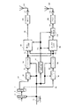
- FIG. 33 shows a transmission apparatus based on the DVB-NGH (Digital Video Broadcasting-Next Generation Generation Handheld) standard described in Non-Patent Document 1 when the number of transmission antennas is 2 and the number of transmission modulation signals (transmission streams) is 2.
- data 1 is input, and data 3 encoded by the encoding unit 2 is divided into data 5A and data 5B by the distribution unit 4.
- Data 5A is subjected to interleaving processing by interleaver 4A, and mapping processing is performed by mapping unit 6A.
- the data 5B is subjected to interleaving processing by the interleaver 4B, and mapping processing is performed by the mapping unit 6B.
- the encoding process in the encoder 2, the interleaving process in the interleavers 4A and 4B, and the mapping process in the mapping units 6A and 6B are executed by setting information included in the frame configuration signal 13.
- Each of the weighting synthesis units 8A and 8B receives the mapped signals 7A and 7B as input and performs weighting synthesis. Thereby, the signals 9A and 16B after the weighted synthesis are generated. The signal 16B after the weighted synthesis is then subjected to phase change by the phase changing unit 17B, and the signal 9B after the phase change is output. Then, the radio units 10A and 10B perform, for example, processing related to OFDM (orthogonal frequency division) multiplexing, frequency conversion, amplification, and the like, the transmission signal 11A is transmitted from the antenna 12A, and the transmission signal 11B is transmitted from the antenna 12B. Is sent.
- OFDM orthogonal frequency division
- the weighting synthesis processing in the weighting synthesis units 8A and 8B and the phase change processing in the phase change unit 17B are performed based on the signal processing method information 115 generated by the signal processing method information generation unit 114.
- the signal processing method information generation unit 114 generates signal processing method information 115 based on the frame configuration signal 13. At this time, in the phase changing unit 17B, for example, nine phase change values are provided, and the phase change with a period of 9 is regularly performed.
- This increases the possibility of avoiding a steady reception state in an environment where the direct wave is dominant, and improves the reception quality of data in the receiving apparatus that is the communication partner.
- the transmitting apparatus in FIG. 33 does not consider transmitting modulated signals to a plurality of terminals (a plurality of users) using the same time and the same frequency.
- one aspect of the present disclosure is a transmission device that transmits a modulated signal to a plurality of terminals (a plurality of users) using the same time and the same frequency, and a plurality of the signals are transmitted to each terminal (each user).
- a modulated signal of a single stream it is possible to provide a transmitter capable of avoiding a constantly poor reception state in an environment where a direct wave is dominant. Thereby, the reception quality of the data of the receiving apparatus which is a communication partner can be improved.
- a transmitting apparatus includes M signal processing units that generate modulation signals for M receiving apparatuses (M is an integer of 2 or more), and each of the M signal processing units.
- M is an integer of 2 or more
- each of the M signal processing units When a plurality of streams are transmitted to a corresponding receiving apparatus, two mapped signals to be transmitted to the corresponding receiving apparatus are generated, and the first precoding is performed by precoding the two mapped signals.
- a precoding unit for generating a coded signal and a second precoded signal; and a phase change for the second precoded signal by periodically changing the phase of a signal point in an IQ plane A phase change unit that outputs the modulated signal, and outputs the first precoded signal and the phase changed signal as two modulation signals, and each of the M signal processing units
- N N Is a multiple signal processing unit that generates a multiple signal of 1
- N antenna units each having at least one antenna element and transmitting the N multiple signals.
- the transmission apparatus When transmitting a plurality of streams of modulated signals to each terminal (each user), the transmission apparatus according to the present disclosure avoids falling into a bad reception state in a steady state in an environment where the direct wave is dominant. be able to. Thereby, the reception quality of the data of the receiving apparatus which is a communication partner can be improved.
- the figure which shows an example of a structure of the transmitter in embodiment of this indication The figure which shows an example of a structure of the signal processing part for user #p
- the figure which shows an example of a structure of the signal processing part in FIG. The figure which shows the example different from FIG. 3 of the structure of the signal processing part in FIG.
- the figure which shows an example of the frame structure of the 1st baseband signal for user #p The figure which shows an example of the frame structure of the 2nd baseband signal for user #p
- the figure which shows the example of the arrangement method of the symbol with respect to a time axis The figure which shows the example of the arrangement method of the symbol with respect to a frequency axis
- positioning of the symbol with respect to a time and a frequency axis The figure which shows the example of arrangement of the symbol with respect to the time axis
- FIG. 11 illustrates an example of a structure of a reception device in this embodiment
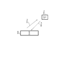
- a diagram showing the relationship between a transmitter and a receiver The figure which shows an example of a structure of the antenna part of FIG.
- the figure which shows an example of a structure which a base station (AP) comprises with the transmitter of FIG.
- the figure which shows an example of the structure which a terminal comprises with the receiver of FIG.
- the figure which shows an example of the relationship between a base station (AP) and a terminal The figure which shows the example of the time flow of communication of a base station (AP) and a terminal
- the figure which shows the example of communication with a base station (AP) and terminal #p The figure which shows the example of the data contained in a reception capability notification symbol The figure which shows the example different from FIG. 28 of the data contained in a reception capability notification symbol The figure which shows the example different from FIG. 28 and FIG. 29 of the data contained in a reception capability notification symbol The figure which shows an example of a structure of the signal processing part for user #p The figure which shows an example of a structure of the signal processing part for user #p The figure which shows an example of a structure of the transmitter based on the DVB-NGH standard described in the nonpatent literature 1 The figure which shows an example of a structure of terminal #p which is a communicating party of the base station shown in FIG.
- the figure which shows an example of a structure of the receiver of terminal #p shown in FIG. The figure which shows an example of the frame structure of the modulation signal of the single stream transmitted using multicarrier transmission systems, such as OFDM system
- the figure which shows an example of the frame structure of the modulation signal of the single stream transmitted using a single carrier transmission system The figure which shows another example of a structure of the signal processing part in FIG.
- combination part The figure which shows an example of a structure of the receiver of terminal #p shown in FIG.
- combination part The figure which shows the 3rd example which arrange
- combination part The figure which shows the 4th example which arrange
- combination part The figure which shows the 6th example which arrange
- combination part The figure which shows the 3rd example which arrange
- combination part The figure which shows the 4th example which arrange
- combination part The figure which shows the 8th example which arrange
- combination part The figure which shows the 9th example which arrange
- combination part The figure which shows an example of a structure of the signal processing part for user #p different from FIG. The figure which shows the 1st example of the state of the signal point transmitted in the transmitter containing the structure of FIG.
- the figure which shows the 1st example of the state of the signal point of the signal received in the receiving apparatus of the communicating party of the transmission apparatus containing the structure of FIG. The figure which shows the 2nd example of the state of the signal point of the signal transmitted in the transmitter containing the structure of FIG.
- the figure which shows the 2nd example of the state of the signal point of the signal received in the receiving apparatus of the communicating party of the transmission apparatus containing FIG. The figure which shows the structural example different from FIG. 1 of the transmitter of a base station (AP).
- AP base station
- FIG.28, FIG.29, FIG.30 of the data contained in a reception capability notification symbol Diagram showing an example of frame configuration
- the figure which shows an example of the structure which added the phase change part The figure which shows the 1st structural example of the signal processing part for user #p of FIG. 1, FIG.
- the figure which shows the 2nd example of the structure contained in a control information symbol etc. The figure which shows an example of a structure of a 1st signal processing part.
- the figure which shows an example of the relationship between a base station (AP) and a terminal The figure which shows the structural example different from FIG. 1 of the transmitter of a base station (AP).
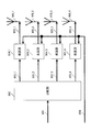
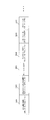
- FIG. 1 is a diagram illustrating an example of a configuration of a transmission device according to the present embodiment.
- the transmission apparatus illustrated in FIG. 1 is, for example, a base station, an access point, a broadcast station, or the like.
- the transmitting device generates a plurality of modulated signals to be transmitted from the receiving device (terminal) of user # 1 to M receiving devices (terminals) of user #M (M is an integer of 2 or more).
- 1 includes a user # 1 signal processing unit 102_1 to a user #M signal processing unit 102_M, a multiple signal processing unit 104, a radio unit $ 1 (106_1) to a radio unit $ N (106_N), and an antenna unit. $ 1 (108_1) to antenna part $ N (108_N) (N is an integer of 1 or more).
- User # 1 signal processing section 102_1 receives control signal 100 and user # 1 data 101_1 as inputs.
- the user # 1 signal processing unit 102_1 transmits a transmission method (for example, an error correction coding method (error correction code coding rate, error correction) for generating a modulation signal for user # 1 included in the control signal 100.
- a transmission method for example, an error correction coding method (error correction code coding rate, error correction) for generating a modulation signal for user # 1 included in the control signal 100.
- Code length for example, modulation scheme, transmission method (for example, single stream transmission, multiple stream transmission, etc.) information is processed, and the first baseband signal 103_1_1 for user # 1 and / or The second baseband signal 103_1_2 for user # 1 is generated.
- the signal processing unit 102_1 for the user # 1 outputs the generated first baseband signal 103_1_1 for the user # 1 and / or the second baseband signal 103_1_2 for the user # 1 to the multiplexed signal processing unit 104. .
- the control signal 100 includes information indicating that multi-stream transmission is selected
- the user # 1 signal processing unit 102_1 includes the first baseband signal 103_1_1 for the user # 1 and the user # 1. 1 second baseband signal 103_1_2 is generated.
- the signal processing unit 102_1 for the user # 1 generates the first baseband signal 103_1_1 for the user # 1.
- the signal processing unit 102_2 for the user # 2 receives the control signal 100 and the data 101_2 for the user # 2.
- the signal processing unit 102_2 for user # 2 generates a transmission method (for example, error correction coding method (error correction code coding rate, error correction) for generating a modulation signal for user # 2 included in the control signal 100. Code length), modulation scheme, transmission method (for example, single stream transmission, multiple stream transmission, etc.) information is processed, and the first baseband signal 103_2_1 for user # 2 and / or The second baseband signal 103_2_2 for user # 2 is generated.
- the signal processing unit 102_2 for user # 2 outputs the generated first baseband signal 103_2_1 for user # 2 and / or second baseband signal 103_2_2 for user # 2 to the multiplexed signal processing unit 104. .
- the signal processing unit 102_2 for the user # 2 includes the first baseband signal 103_2_1 for the user # 2 and the user # 2. 2 baseband signal 103_2_2 for 2 is generated.
- the user # 2 signal processing unit 102_2 When information indicating that single stream transmission is selected is included in the control signal 100, the user # 2 signal processing unit 102_2 generates the first baseband signal 103_2_1 for the user # 2.
- the signal processing unit 102_M for the user #M receives the control signal 100 and the data 101_M for the user #M as inputs.
- the user # 1 signal processing unit 102_1 transmits a transmission method (for example, error correction coding method (error correction code coding rate, error correction) for generating a modulation signal for user #M included in the control signal 100. Code length), modulation scheme, transmission method (for example, single stream transmission, multiple stream transmission, etc.) information, signal processing is performed, first baseband signal 103_M_1 for user #M, and / or , The second baseband signal 103_M_2 of the user #M is generated.
- the user #M signal processing unit 102_M outputs the generated first baseband signal 103_M_1 for user #M and / or second baseband signal 103_M_2 for user #M to the multiple signal processing unit 104.
- the user #M signal processing unit 102_M when the control signal 100 includes information indicating that multi-stream transmission is selected, the user #M signal processing unit 102_M includes the first baseband signal 103_M_1 for the user #M and the user #M. A second baseband signal 103_M_2 for M is generated.
- the user #M signal processing unit 102_M When information indicating that single stream transmission is selected is included in the control signal 100, the user #M signal processing unit 102_M generates the first baseband signal 103_M_1 for the user #M.
- the signal processing unit 102_p for user #p receives the control signal 100 and the data 101_p for user #p.
- the signal processing unit 102_p for user #p generates a transmission method (for example, error correction coding method (coding rate of error correction code, error correction code) for generating a modulation signal for user #p included in the control signal 100. Code length), modulation scheme, transmission method (for example, single stream transmission, multiple stream transmission, etc.) information, signal processing is performed and first baseband signal 103_p_1 for user #p, and / or , The second baseband signal 103_p_2 of the user #p is generated.
- the user #p signal processing unit 102_p outputs the generated first baseband signal 103_p_1 for user #p and / or the second baseband signal 103_p_2 for user #p to the multiple signal processing unit 104.
- the signal processing unit 102_p for the user #p receives the first baseband signal 103_p_1 for the user #p and the user #p.
- a second baseband signal 103_p_2 for p is generated.
- the signal processing unit 102_p for user #p generates a first baseband signal 103_p_1 for user #p.
- the configurations of the user # 1 signal processing unit 102_1 to the user #M signal processing unit 102_M will be described later using the configuration of the user #p signal processing unit as an example.
- the control signal 100 includes information indicating which one of the multi-stream transmission and the single-stream transmission is selected for each of the user # 1 signal processing unit 102_1 to the user #M signal processing unit 102_M. .
- the multiplexed signal processing unit 104 includes a control signal 100, a first baseband signal 103_1_1 for user # 1, a second baseband signal 103_1_2 for user # 1, a first baseband signal 103_2_1 for user # 2, Second baseband signal 103_2_2 for user # 2,..., First baseband signal 103_M_1 for user #M, second baseband signal 103_M_2 for user #M, (common) reference signal 199
- Multiplex signal processing section 104 performs multiple signal processing based on control signal 100 to generate baseband signal 105_1 of multiplexed signal $ 1 to baseband signal 105_N of multiplexed signal $ N (N is an integer of 1 or more).
- the multiplexed signal processing unit 104 outputs the generated baseband signal 105_1 of the multiplexed signal $ 1 to baseband signal 105_N of the multiplexed signal $ N to the corresponding wireless unit (wireless unit $ 1 to wireless unit $ N).
- the reference signal 199 is a signal transmitted from the transmission device so that the reception device estimates the propagation environment.
- a (common) reference signal 199 is inserted for each user's baseband signal. The multiple signal processing will be described later.
- Radio unit $ 1 receives control signal 100 and baseband signal 105_1 of multiplexed signal $ 1 as inputs.
- Radio section $ 1 (106_1) performs processing such as frequency conversion and amplification based on control signal 100, and outputs transmission signal 107_1 to antenna section $ 1 (108_1).
- the antenna unit $ 1 (108_1) receives the control signal 100 and the transmission signal 107_1.
- the antenna unit $ 1 (108_1) performs processing on the transmission signal 107_1 based on the control signal 100. However, in the antenna unit $ 1 (108_1), the control signal 100 may not exist as an input. Transmission signal 107_1 is output as a radio wave from antenna unit $ 1 (108_1).
- Radio unit $ 2 receives control signal 100 and baseband signal 105_2 of multiplexed signal $ 2.
- Radio section $ 2 (106_2) performs processing such as frequency conversion and amplification based on control signal 100, and outputs transmission signal 107_2 to antenna section $ 2 (108_2).
- the antenna unit $ 2 (108_2) receives the control signal 100 and the transmission signal 107_2.
- the antenna unit $ 2 (108_2) performs processing on the transmission signal 107_2 based on the control signal 100.
- the control signal 100 may not exist as an input.
- Transmission signal 107_2 is output as a radio wave from antenna unit $ 2 (108_2).
- Radio unit $ N receives control signal 100 and baseband signal 105_N of multiplexed signal $ N as inputs. Radio section $ N (106_N) performs processing such as frequency conversion and amplification based on control signal 100, and outputs transmission signal 107_N to antenna section $ N (108_N).
- the antenna unit $ N (108_N) receives the control signal 100 and the transmission signal 107_N.
- the antenna unit $ N (108_N) performs processing on the transmission signal 107_N based on the control signal 100.
- the control signal 100 may not exist as an input.
- the transmission signal 107_N is output as a radio wave from the antenna unit $ N (108_N).
- the radio unit $ n (106_n) receives the control signal 100 and the baseband signal 105_n of the multiplexed signal $ n as inputs. Radio unit $ n (106_n) performs processing such as frequency conversion and amplification based on control signal 100, and outputs transmission signal 107_n to antenna unit $ n (108_n).
- the antenna unit $ n (108_n) receives the control signal 100 and the transmission signal 107_n.
- the antenna unit $ n (108_n) performs processing on the transmission signal 107_n based on the control signal 100.
- the control signal 100 may not exist as an input in the antenna unit $ n (108_n).
- the transmission signal 107_n is output as a radio wave from the antenna unit $ n (108_n).
- radio unit $ 1 to radio unit $ N and antenna units $ 1 to $ N An example of the configuration of radio unit $ 1 to radio unit $ N and antenna units $ 1 to $ N will be described later.
- the control signal 100 may be generated based on the information transmitted to the transmitting device in FIG. 1 by the receiving device that is the communication partner in FIG. 1, or the transmitting device in FIG. And may be generated based on information input from the input unit.
- the transmission apparatus of FIG. 1 not all of the signal processing unit for user # 1 (102_1) to the signal processing unit for user #M (102_M) need to operate. All may be operating, or some may be operating. That is, the number of users with which the transmission apparatus is communicating is 1 or more and M or less. The number of communication partners (users) to which the transmission device in FIG. 1 transmits a modulated signal is 1 or more and M or less.
- wireless unit $ 1 (106_1) to the wireless unit $ N (106_N) may not be operating. All may be operating, or some may be operating. Further, all of antenna unit $ 1 (108_1) to antenna unit $ N (108_N) may not be operating. All may be operating, or some may be operating.
- the transmission apparatus of FIG. 1 can transmit a plurality of user modulation signals (baseband signals) using the same time and the same frequency (band) by using a plurality of antennas.
- the transmission apparatus in FIG. 1 includes a first baseband signal 103_1_1 for user # 1, a second baseband signal 103_1_2 for user # 1, and a first baseband signal for user # 2.
- 103_2_1 and the second baseband signal 103_2_2 for user # 2 can be transmitted using the same time and the same frequency (band).
- 1 transmits the first baseband signal 103_1_1 for user # 1, the second baseband signal 103_1_2 for user # 1, and the first baseband signal for user # 2.
- 103_2_1 can be transmitted using the same time and the same frequency (band).
- the combination of modulated signals (baseband signals) of a plurality of users transmitted by the transmission apparatus in FIG. 1 is not limited to this example.
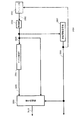
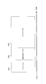
- FIG. 2 is a diagram illustrating an example of the configuration of the user #p signal processing unit 102_p.
- the user #p signal processing unit 102_p includes an error correction coding unit 202, a mapping unit 204, and a signal processing unit 206.
- the error correction coding unit 202 receives the data 201 for the user #p and the control signal 200 as inputs.
- the control signal 200 corresponds to the control signal 100 in FIG. 1
- the data 201 for user #p corresponds to the data 101_p for user #p in FIG.
- the error correction coding unit 202 performs error correction coding based on information on the error correction code included in the control signal 200 (for example, error correction code information, code length (block length), coding rate), and
- the encoded data 203 for #p is output to the mapping unit 204.
- the error correction coding unit 202 may include an interleaver. If the error correction encoding unit 202 includes an interleaver, the error correction encoding unit 202 rearranges the data after encoding, and outputs encoded data 203 for user #p.
- Mapping section 204 receives encoded data 203 for user #p and control signal 200 as inputs.
- the mapping unit 204 performs mapping corresponding to the modulation scheme based on the modulation scheme information included in the control signal 200, and performs the mapped signal (baseband signal) 205_1 for user #p and / or after mapping.
- a signal (baseband signal) 205_2 is generated.
- the mapping unit 204 outputs the generated mapped signal (baseband signal) 205_1 and / or the mapped signal (baseband signal) 205_2 for the user #p to the signal processing unit 206.
- mapping unit 204 separates the encoded data 203 for the user #p into the first sequence and the second sequence when the control signal 200 includes information indicating that multi-stream transmission is selected. To do. Then, mapping section 204 generates mapped signal 205_1 for user #p using the first sequence, and generates mapped signal 205_2 for user #p using the second sequence. . At this time, it is assumed that the first sequence and the second sequence are different. However, even if the first series and the second series are the same series, the same implementation can be performed.
- the mapping unit 204 separates the encoded data 203 for user #p into three or more sequences, and each sequence The mapping may be performed using, and three or more mapped signals may be generated. In this case, three or more series may be different from each other, and a part or all of the three or more series may be the same series.
- the mapping unit 204 uses the encoded data 203 for the user #p as one sequence and performs mapping after the mapping for the user #p.
- a signal 205_1 is generated.
- the signal processor 206 receives the mapped signal 205_1 for the user #p and / or the mapped signal 205_2 for the user #p, the signal group 210, and the control signal 200.
- the signal processing unit 206 performs signal processing based on the control signal 200, and outputs post-signal processing signals 207_A and 207_B for the user #p.
- the signal 207_A after the signal processing for the user #p corresponds to the first baseband signal 103_p_1 for the user #p in FIG. 1, and the signal 207_B after the signal processing for the user #p is the user #p in FIG. This corresponds to the first baseband signal 103_p_2 for p.
- the signal 207_A after the signal processing for the user #p is represented as up1 (i)
- the signal 207_B after the signal processing for the user #p is represented as up2 (i).
- i is a symbol number.
- i is an integer of 0 or more.
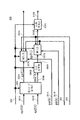
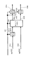
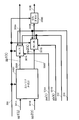
- FIG. 3 is a diagram illustrating an example of the configuration of the signal processing unit 206 in FIG.
- the signal processing unit 206 includes a weighting synthesis unit 303, a phase change unit 305B, an insertion unit 307A, an insertion unit 307B, and a phase change unit 309B.
- the mapping unit 204 uses the information indicating that the multi-stream transmission is selected, the mapped signal 205_1 for the user #p, and the mapped signal for the user #p. A case where 205_2 is generated will be described.
- the weighting synthesis unit (precoding unit) 303 receives the mapped signal 301A for user #p, the mapped signal 301B for user #p, and the control signal 300.
- the mapped signal 301A for user #p corresponds to the mapped signal 205_1 for user #p in FIG. 2, and the mapped signal 301B for user #p is mapped for user #p in FIG. This corresponds to the later signal 205_2.
- the control signal 300 corresponds to the control signal 200 in FIG.
- the weighting synthesis unit 303 performs weighting synthesis (precoding) based on the control signal 300, and generates a weighted signal 304A for the user #p and a weighted signal 304B for the user #p. Weighting synthesis section 303 outputs weighted signal 304A for user #p to insertion section 307A. Weighting synthesis section 303 outputs weighted signal 304B for user #p to phase changing section 305B.
- User #p mapped signal 301A is sp1 (t)
- user #p mapped signal 301B is sp2 (t)
- user #p weighted signal 304A is zp1 (t)
- user #p The weighted signal 304B for p is represented as zp2 ′ (t).
- t is time as an example.
- sp1 (t), sp2 (t), zp1 (t), and zp2 '(t) are defined as complex numbers. Accordingly, sp1 (t), sp2 (t), zp1 (t), and zp2 '(t) may be real numbers.
- the weighting synthesis unit 303 performs a calculation based on the following equation (1).
- a, b, c, and d are defined as complex numbers.
- a, b, c, and d may be real numbers.
- i is a symbol number.
- the phase changing unit 305B receives the weighted signal 304B and the control signal 300 as inputs. Based on the control signal 300, the phase changing unit 305B changes the phase of the weighted signal 304B, and outputs the phase-changed signal 306B to the inserting unit 307B.
- the signal 306B after the phase change is represented by zp2 (t).
- zp2 (t) is defined as a complex number. Note that zp2 (t) may be a real number.
- phase changing unit 305B The specific operation of the phase changing unit 305B will be described.
- i is a symbol number (i is an integer of 0 or more).
- the phase changing unit 305B sets the value of the phase change expressed as yp (i) as in the following equation (2).
- j is an imaginary unit.
- Np is an integer of 2 or more, and indicates a phase change period. If Np is set to an odd number of 3 or more, the data reception quality may be improved.
- the phase change value yp (i) is not limited to the equation (2).
- a method of changing the phase periodically or regularly can be considered.
- the matrix used for the calculation of the weighting synthesis unit 303 shown in Expression (1) and Expression (3) will be described.
- the matrix used for the calculation of the weighting synthesis unit 303 is represented by Fp as shown in the following equation (4).
- ⁇ may be a real number or an imaginary number.
- ⁇ may be a real number or an imaginary number.
- ⁇ is not 0 (zero).
- ⁇ is not 0 (zero).
- ⁇ is a real number.
- ⁇ may be a real number or an imaginary number. However, ⁇ is not 0 (zero).
- ⁇ 11 (i), ⁇ 21 (i), and ⁇ (i) are functions of i (symbol number) and real values.
- ⁇ is a real fixed value, for example. Note that ⁇ does not have to be a fixed value. ⁇ may be a real number or an imaginary number. ⁇ may be a real number or an imaginary number. However, ⁇ is not 0 (zero). ⁇ is not 0 (zero). Further, ⁇ 11 and ⁇ 21 are real numbers.
- ⁇ may be a real number or an imaginary number. However, ⁇ is not 0 (zero).
- each embodiment can be implemented even if a precoding matrix different from the above equations (5) to (36) is used.
- the weighting synthesis unit 303 in FIG. 3 does not perform signal processing on the mapped signals 301A and 301B.
- the mapped signal 301A is output as a weighted signal 304A
- the mapped signal 301B is output as a weighted combined signal 304B.
- the weighting / synthesizing unit 303 may not exist, and when the weighting / synthesizing unit 303 exists, the control signal 300 may be controlled to perform weighting synthesis or not to perform weighting synthesis.
- Insertion section 307A receives weighted signal 304A, pilot symbol signal (pa (t)) (351A), preamble signal 352, control information symbol signal 353, and control signal 300. Insertion unit 307A outputs baseband signal 308A based on the frame configuration to multiplexed signal processing unit 104 based on the information on the frame configuration included in control signal 300.
- insertion section 307B receives signal 306B after the phase change, pilot symbol signal (pb (t) (351B), preamble signal 352, control information symbol signal 353, and control signal 300. Insertion section 307B Based on the frame configuration information included in the control signal 300, the baseband signal 308B based on the frame configuration is output to the phase changing unit 309B.
- control information for generating the control information symbol signal 353 and a frame configuration in the transmission device used in the insertion unit 307A and the insertion unit 307B will be described later.
- the phase changing unit 309B receives the baseband signal 308B and the control signal 300 as inputs.
- the phase changing unit 309B changes the phase of the baseband signal 308B based on the control signal 300, and outputs the signal 310B after the phase change to the multiplexed signal processing unit 104.
- phase changing unit 309B may be CDD (Cyclic Delay Diversity) (CSD (Cyclic Shift Diversity)) described in Non-Patent Document 2 and Non-Patent Document 3.
- a feature of the phase changing unit 309B is that the phase is changed for symbols existing in the frequency axis direction.
- Phase change section 309B performs phase change on data symbols, pilot symbols, control information symbols, and the like.
- the phase changing unit 309B may not be included in the signal processing unit 206. Alternatively, even when the phase changing unit 309B is included in the signal processing unit 206, whether or not to operate may be switched.
- the insertion unit 307B outputs the baseband signal 308B to the multiplexed signal generation unit 104 in FIG.
- the baseband signal 308B is output to the multiplexed signal processing unit 104 instead of the signal 310B after the phase change. Signal.
- the phase changing unit 309B does not operate will be described.
- the weighting synthesis unit 303 applies the signals 301A and 301B after mapping.
- the signal 301A after mapping is output as a signal 304A after weighting without performing signal processing for weighting synthesis
- the signal 301B after mapping is output as a signal 304B after weighting.
- the weighting / combining unit 303 performs (i) signal processing corresponding to weighting synthesis to generate and output weighted signals 304A and 304B, and (ii) weighting synthesis. (Ii) the process of outputting the signal 301A after mapping as a weighted signal 304A, and outputting the signal 301B after mapping as a weighted signal 304B, without performing signal processing for (ii) Control to switch between these processes.
- the mapping unit 204 in FIG. 2 generates two series of signals when multiple stream transmission is selected for the user #p has been described.
- the weighting synthesis unit 303, the phase change unit 306B, and the insertion unit 307B in FIG. 3 do not operate, and after the mapping for the user #p
- the signal 301A may be input to the insertion unit 307A without being weighted.
- the signal processing unit 102_p for user #p in FIG. 1 does not include the weighting synthesis unit 303, the phase change unit 306B, and the insertion unit 307B in the configuration of FIG. May be.
- the mapping unit 204 in FIG. 2 may generate three or more series of signals.
- the weighting synthesis unit 303 in FIG. 3 performs weighting synthesis using a precoding matrix according to the number of input signals, for example, Three or more weighted signals are output. Note that the number of signals input to the weighting synthesis unit 303 in FIG. 3 and the number of signals output from the weighting synthesis unit 303 may not be the same. That is, the precoding matrix used in the weighting synthesis unit 303 may not be a square matrix.
- the signal processing unit 102_p may change the phase of all or part of the three or more weighted signals. .
- the phase change may not be performed on all of the three or more weighted signals that are output.
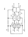
- FIG. 4 is a diagram illustrating an example different from FIG. 3 of the configuration of the signal processing unit 206 in FIG. In FIG. 4, the same components as those in FIG. The description of the same configuration as in FIG. 3 is omitted here.
- 4 is configured such that a coefficient multiplier 401A and a coefficient multiplier 401B are added to the signal processor 206 of FIG.
- the coefficient multiplier 401A receives the mapped signal 301A (sp1 (i)) and the control signal 300 as inputs. Based on control signal 300, coefficient multiplication section 401A multiplies signal 301A after mapping (sp1 (i)) by a coefficient, and outputs signal 402A after coefficient multiplication to weighting synthesis section 303.
- the coefficient is up
- the signal 402A after the coefficient multiplication is expressed as up ⁇ sp1 (i). Up may be a real number or a complex number. However, up is not 0 (zero).
- the signal 402A is output.
- the coefficient multiplier 401B receives the mapped signal 301B (sp2 (i)) and the control signal 300 as inputs.
- Coefficient multiplication section 401B multiplies signal 301B (sp2 (i)) after mapping based on control signal 300 by a coefficient, and outputs signal 402B after coefficient multiplication to weighting synthesis section 303.
- the coefficient is vp
- the signal 402B after the coefficient multiplication is expressed as vp ⁇ sp2 (i).
- vp may be a real number or a complex number. However, vp is not 0 (zero).
- the coefficient multiplication unit 401B does not multiply the mapped signal 301B (sp2 (i)) by a coefficient, and after the mapped signal 301B (sp2 (i)) is multiplied by a coefficient.
- the signal 402B is output.
- the weighted signal 304A (zp1 (i)) output from the weighting / combining unit 303 and the phase changed signal 306B (zp2 (i)) output from the phase changing unit 305B are multiplied by coefficients.
- the coefficient up of the unit 401A, the coefficient vp of the coefficient multiplying unit 401B, and the equation (3) it is expressed by the following equation (37).
- examples of the (precoding) matrix Fp are Expressions (5) to (36) as described above.
- the example of the phase change value yp (i) is represented by the expression (2).
- the (precoding) matrix Fp and the phase change value yp (i) are not limited to these. Absent.
- the method in which the user #p signal processing unit 102_p generates a symbol has been described using FIGS. 1 to 4 and equations (1) to (37) as examples.
- the generated symbols may be arranged in the time axis direction. Further, when a multicarrier scheme such as OFDM (Orthogonal Frequency Division Multiplexing) is used, the generated symbols may be arranged in the frequency axis direction or in the time / frequency direction. Further, the generated symbols are interleaved (that is, rearranged symbols), and may be arranged in the time axis direction, in the frequency axis direction, or in the time / frequency axis direction. You may arrange.
- OFDM Orthogonal Frequency Division Multiplexing
- the symbol arrangement is performed in the signal processing unit 102_p for user #p, for example, in the error correction coding unit 202 and / or the mapping unit 204 shown in FIG.
- the signal processing unit 102_1 for the user # 1 generates the baseband signal 103_1_1 for the user # 1 and the baseband signal 103_1_2 for the user # 1 using the equation (3) or the equation (37).
- the signal processing unit 102_2 for the user # 2 generates the baseband signal 103_2_1 for the user # 2 and the baseband signal 103_2_2 for the user # 2 using the equation (3) or the equation (37).
- the user #M signal processing unit 102_M generates a baseband signal 103_M_1 for user #M and a baseband signal 103_M_2 for user #M.
- the precoding matrix Fp and / or the phase change value yp (i) used in the signal processing unit 102_p for the user #p is set according to the value of p, that is, for each user.
- Information for setting the precoding matrix Fp and / or the phase change value yp (i) is included in the control signal.
- all of the user # 1 signal processing unit 102_1 to the user #M signal processing unit 102_M in FIG. 1 need not apply precoding and phase change.
- a signal processing unit that does not change the phase may exist among the user # 1 signal processing unit 102_1 to the user #M signal processing unit 102_M.
- a signal processing unit that generates one baseband signal may exist in the signal processing unit 102_1 for user # 1 to the signal processing unit 102_M for user # 1. .
- the phase changing unit 305B does not change the phase
- the weighted signal 304B may be output as 306B without changing the phase of the weighted signal 304B.
- i is a symbol number, for example, an integer of 0 or more.
- the signals b ⁇ 2p-1 ⁇ (i) and b ⁇ 2p ⁇ (i) are represented by the following equations (38) and (39).
- the first baseband signal 103_1_1 for user # 1 and the second baseband signal 103_1_2 for user # 1 are represented by b ⁇ 1 ⁇ (i) and b ⁇ 2 ⁇ (i), respectively. . That is, when the signal processing unit 102_1 for the user # 1 to the signal processing unit 102_M for the user #M output two signals, the output signals are b ⁇ 1 ⁇ (i) to b ⁇ 2M ⁇ . Represented as (i).
- the baseband signal 105_1 of the multiplexed signal $ 1 to the baseband signal 105_N of the multiplexed signal $ N, which are outputs of the multiplexed signal processing unit 104, are denoted by v1 (i) to vN (i), respectively. That is, the baseband signal 105_n of the multiplexed signal $ n becomes vn (i).
- N is an integer of 1 or more and N or less
- vn (i) can be expressed by the following equation (40).
- ⁇ ⁇ n ⁇ ⁇ k ⁇ is a multiplexing weighting coefficient and can be defined by a complex number. Therefore, ⁇ ⁇ n ⁇ ⁇ k ⁇ may be a real number.
- ⁇ ⁇ n ⁇ ⁇ k ⁇ is determined by feedback information of each terminal.
- the user #p signal processing unit 102_p in FIG. 1 is described as an example in which one or two modulation signals are output.
- the signal processing unit 102_p for user #p may output three or more modulation signals. In that case, the processing of the multiple signal processing unit 104 needs to be expressed by an expression different from Expression (40).
- radio unit $ 1 (106_1) to the radio unit $ N (106_N) in FIG. 1 perform processing such as frequency conversion and amplification on the signals input to each to generate a transmission signal.
- radio unit $ 1 (106_1) to radio unit $ N (106_N) may use either a single carrier scheme or a multicarrier scheme such as an OFDM (Orthogonal Frequency Division Multiplexing) scheme.
- OFDM Orthogonal Frequency Division Multiplexing
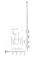
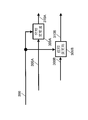
- FIG. 5 is a diagram illustrating an example of the configuration of the radio unit $ n (106_n) in which the OFDM scheme is used.
- the radio unit $ n (106_n) includes a serial / parallel conversion unit 502, an inverse Fourier transform unit 504, and a processing unit 506.
- the serial / parallel converter 502 receives the signal 501 and the control signal 500 as inputs.
- the serial / parallel conversion unit 502 performs serial / parallel conversion of the input signal 501 based on the control signal 500, and outputs the signal 503 after the serial / parallel conversion to the inverse Fourier transform unit 504.
- Signal 501 corresponds to baseband signal 105_n of multiplexed signal $ n in FIG. 1
- control signal 500 corresponds to control signal 100 in FIG.
- the inverse Fourier transform unit 504 receives the signal 503 after the serial / parallel conversion and the control signal 500 as inputs. Based on the control signal 500, the inverse Fourier transform unit 504 performs an inverse Fourier transform (for example, inverse fast Fourier transform (IFFT)), and outputs a signal 505 after the inverse Fourier transform to the processing unit 506. .
- an inverse Fourier transform for example, inverse fast Fourier transform (IFFT)
- the processing unit 506 receives the signal 505 after the inverse Fourier transform and the control signal 500 as inputs.
- the processing unit 506 performs processing such as frequency conversion and amplification based on the control signal 500, and outputs a modulated signal 507 to the antenna unit $ n (108_n).
- the modulated signal 507 output from the processing unit 506 corresponds to the transmission signal 107_n in FIG.
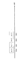
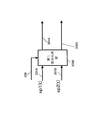
- FIG. 6 is a diagram illustrating an example of a configuration of the antenna unit (antenna unit $ 1 (108_1) to antenna unit $ N (108_N)) in FIG. Note that the configuration of FIG. 6 is an example in which the antenna unit $ 1 (108_1) to the antenna unit $ N (108_N) are configured with four antennas.
- the antenna unit includes a distribution unit 902, multiplication units 904_1 to 904_4, and antennas 906_1 to 906_4.
- the distribution unit 902 receives the transmission signal 901 as an input.
- Distribution section 902 distributes transmission signal 901 and outputs transmission signals 903_1, 903_2, 903_3, and 903_4 to corresponding multiplication sections (multiplication sections 904_1 to 904_4).
- the transmission signal 901 corresponds to the transmission signal 107_1 in FIG. Further, when the configuration of the antenna unit $ 2 (108_2) in FIG. 1 is FIG. 6, the transmission signal 901 corresponds to the transmission signal 107_2 in FIG. When the configuration of the antenna unit $ N (108_N) in FIG. 1 is FIG. 6, the transmission signal 901 corresponds to the transmission signal 107_N in FIG.
- Multiplier 904_1 receives transmission signal 903_1 and control signal 900 as inputs. Multiplication section 904_1 multiplies transmission signal 903_1 by the multiplication coefficient based on information on the multiplication coefficient included in control signal 900, and outputs signal 905_1 after multiplication to antenna 906_1. The multiplied signal 905_1 is output from the antenna 906_1 as a radio wave.
- the transmission signal 903_1 is Tx1 (t) (t: time) and the multiplication coefficient is W1
- the signal 905_1 after multiplication is expressed as Tx1 (t) ⁇ W1.
- W1 can be defined as a complex number, and thus may be a real number.
- Multiplier 904_2 receives transmission signal 903_2 and control signal 900 as inputs. Multiplier 904_2 multiplies transmission signal 903_2 by the multiplication coefficient based on information on the multiplication coefficient included in control signal 900, and outputs signal 905_2 after multiplication to antenna 906_2. The multiplied signal 905_2 is output from the antenna 906_2 as a radio wave.
- the transmission signal 903_2 is Tx2 (t) and the multiplication coefficient is W2
- the signal 905_2 after multiplication is expressed as Tx2 (t) ⁇ W2.
- W2 can be defined as a complex number, and thus may be a real number.
- Multiplier 904_3 receives transmission signal 903_3 and control signal 900 as inputs. Multiplication section 904_3 multiplies transmission signal 903_3 by the multiplication coefficient based on information on the multiplication coefficient included in control signal 900, and outputs signal 905_3 after multiplication to antenna 906_3. The multiplied signal 905_3 is output from the antenna 906_3 as a radio wave.
- the transmission signal 903_3 is Tx3 (t) and the multiplication coefficient is W3
- the signal 905_3 after multiplication is expressed as Tx3 (t) ⁇ W3.
- W3 can be defined as a complex number, and thus may be a real number.
- Multiplier 904_4 receives transmission signal 903_4 and control signal 900 as inputs. Multiplication section 904_4 multiplies transmission signal 903_4 by the multiplication coefficient based on information on the multiplication coefficient included in control signal 900, and outputs signal 905_4 after multiplication to antenna 906_4. The multiplied signal 905_4 is output from the antenna 906_4 as a radio wave.
- the transmission signal 903_4 is Tx4 (t) and the multiplication coefficient is W4
- the signal 905_4 after multiplication is expressed as Tx4 (t) ⁇ W4.
- W4 can be defined as a complex number, and thus may be a real number.
- the absolute value of W1, the absolute value of W2, the absolute value of W3, and the absolute value of W4 may be equal”. At this time, this corresponds to the fact that the phase has been changed. As a matter of course, the absolute value of W1, the absolute value of W2, the absolute value of W3, and the absolute value of W4 may not be equal.
- FIG. 6 illustrates an example in which each antenna unit includes four antennas (and four multiplication units).
- the number of antennas is not limited to four, and 1 What is necessary is just to be comprised with the antenna more than this.
- antenna unit $ 1 (108_1) to antenna unit $ N (108_N) do not have to be configured as shown in FIG. 6, and the antenna unit does not have to receive control signal 100 as described above.
- each of antenna unit $ 1 (108_1) to antenna unit $ N (108_N) in FIG. 1 may be configured by one antenna or may be configured by a plurality of antennas.
- FIG. 7 is a diagram illustrating an example of a configuration of a part related to control information generation for generating the control information symbol signal 353 of FIGS. 3 and 4.
- the control information mapping unit 802 receives the control information data 801 and the control signal 800 as inputs.
- the control information mapping unit 802 performs mapping on the control information data 801 using a modulation scheme based on the control signal 800 and outputs a signal 803 after the control information mapping.
- the control information mapping signal 803 corresponds to the control information symbol signal 353 shown in FIGS.
- the frame configuration indicates an arrangement of transmitted data symbols, pilot symbols, and other symbols.
- the frame configuration information is included in the control signal 300 (see FIGS. 3 and 4).
- the insertion unit 307A and the insertion unit 307B illustrated in FIGS. 3 and 4 respectively generate a baseband signal 308A and a baseband signal 308B based on the frame configuration.
- the insertion unit 307A in the signal processing unit 102_p for the user #p outputs the first baseband signal 103_p_1 for the user #p in FIG. 1 as the baseband signal 308A.
- the insertion unit 307B outputs the second baseband signal 103_p_2 for the user #p in FIG. 1 as the baseband signal 308B.
- the frame configuration will be described using the first baseband signal 103_p_1 for user #p and the second baseband signal 103_p_2 for user #p as examples.
- FIG. 8 is a diagram illustrating an example of a frame configuration of the first baseband signal 103_p_1 for user #p.
- the horizontal axis represents frequency (carrier), and the vertical axis represents time. Since multi-carrier transmission schemes such as OFDM are used, symbols exist in the carrier direction.
- FIG. 8 shows symbols of carrier 1 to carrier 36 as an example.
- FIG. 8 shows symbols from time 1 to time 11.
- pilot symbol signal 351A indicates a pilot symbol
- 602 indicates a data symbol
- 603 indicates other symbols.
- the pilot symbol is, for example, a symbol of PSK (Phase Shift ⁇ Keying), and is a symbol for a receiving apparatus that receives this frame to perform channel estimation (estimation of propagation path fluctuation) and frequency offset / phase fluctuation. It is.
- the transmission apparatus in FIG. 1 and the reception apparatus that receives the signal having the frame configuration in FIG. 8 may share the pilot symbol transmission method.
- the mapped signal 205_1 for the user #p is named “stream # 1,” and the mapped signal 205_2 for the user #p is named “stream # 2.” This point is the same in the following description.
- the data symbol 602 is a symbol corresponding to the data symbol included in the baseband signal 207_A generated in FIG. Therefore, the data symbol 602 is “a symbol including both“ stream # 1 ”symbol and“ stream # 2 ”symbol”, “a symbol of“ stream # 1 ””, or ““ stream # 2 ”. "Symbol”. This is determined by the configuration of the precoding matrix used in the weighting synthesis unit 303 in FIG. That is, the data symbol 602 corresponds to the weighted signal 304A (zp1 (i)).
- the other symbols 603 are symbols corresponding to the preamble signal 352 and the control information symbol signal 353 in FIGS. However, other symbols may include symbols other than the preamble and the control information symbol.
- the preamble may transmit data (for control), a symbol for signal detection, a symbol for frequency synchronization / time synchronization, a symbol for channel estimation (estimation of propagation path fluctuation). Symbol for performing).
- the control information symbol is a symbol including control information for the receiver that receives the frame of FIG. 8 to realize demodulation and decoding of the data symbol.
- carrier 1 to carrier 36 from time 1 to time 4 in FIG. become data symbols 602.
- carrier 12 at time 5 becomes pilot symbol 601
- carrier 13 at time 5 to carrier 23 becomes data symbol 602
- carrier 24 at time 5 becomes pilot symbol 601
- carrier 1 and carrier 2 at time 6 are data symbols 602.
- carrier 3 at time 6 becomes a pilot symbol 601
- carrier 30 at time 11 becomes a pilot symbol 601
- carriers 31 to 36 at time 11 become data symbols 602.
- FIG. 9 is a diagram illustrating an example of a frame configuration of the second baseband signal 103_p_2 for user #p.
- the horizontal axis represents frequency (carrier), and the vertical axis represents time. Since multi-carrier transmission schemes such as OFDM are used, symbols exist in the carrier direction.
- FIG. 9 shows symbols of carrier 1 to carrier 36 as an example.
- FIG. 9 shows symbols from time 1 to time 11.
- 701 in FIG. 9 is a pilot symbol (pilot symbol signal 351B (corresponding to pb (t) in FIGS. 3 and 4)), 702 is a data symbol, and 703 is another symbol.
- the pilot symbol is, for example, a PSK symbol, and is a symbol for a receiving apparatus that receives this frame to perform channel estimation (estimation of propagation path fluctuation) and frequency offset / phase fluctuation.
- the transmission apparatus in FIG. 1 and the reception apparatus that receives the signal having the frame configuration in FIG. 9 may share the pilot symbol transmission method.
- the data symbol 702 is a symbol corresponding to the data symbol included in the baseband signal 207_B generated in FIG. Therefore, the data symbol 702 is “a symbol including both the symbol of“ stream # 1 ”and the symbol of“ stream # 2 ””, “the symbol of“ stream # 1 ””, or “the symbol of“ stream # 2 ”.
- the other symbols 703 are symbols corresponding to the preamble signal 352 and the control information symbol signal 353 in FIGS. However, other symbols may include symbols other than the preamble and the control information symbol.
- the preamble may transmit data (for control), a symbol for signal detection, a symbol for frequency synchronization / time synchronization, a symbol for channel estimation (estimation of propagation path fluctuation). Symbol for performing).
- the control information symbol is a symbol including control information for the receiving apparatus that receives the frame of FIG. 9 to realize demodulation and decoding of the data symbol.
- carrier 1 to carrier 36 from time 1 to time 4 in FIG. become data symbols 702.
- carrier 12 at time 5 becomes pilot symbol 701
- carrier 13 through carrier 23 at time 5 becomes data symbol 702
- carrier 24 at time 5 becomes pilot symbol 701
- carrier 1 and carrier 2 at time 6 are data symbols 702.
- carrier 3 at time 6 becomes pilot symbol 701
- carrier 30 at time 11 becomes pilot symbol 701
- carrier 31 to carrier 36 at time 11 become data symbol 702.
- FIG. 8 When a symbol exists at carrier A and time B in FIG. 8, and when a symbol exists at carrier A and time B in FIG. 9, the symbol at carrier A and time B in FIG. 8 and the symbol at carrier A and time B in FIG. Are transmitted at the same frequency for the same time.
- the frame configuration is not limited to FIGS. 8 and 9, and FIGS. 8 and 9 are only examples of the frame configuration.
- the other symbols 603 and 703 in FIGS. 8 and 9 are symbols corresponding to the “preamble signal 352 and control symbol 353 in FIGS. 3 and 4”. Therefore, the other symbols 703 in FIG. 9 having the same time and the same frequency (same carrier) as the other symbols 603 in FIG. 8 transmit the same data (same control information) when transmitting control information. It is transmitting.
- the receiving apparatus receives the frame in FIG. 8 and the frame in FIG. 9 at the same time, but the receiving apparatus receives only the frame in FIG. 8 or only the frame in FIG. It is also possible to obtain data transmitted by the transmitting device.
- the first baseband signal 103_1_1 and the second baseband signal 103_1_2 are output in the signal processing unit 102_1 for the user # 1 in FIG. 1, the first baseband signal 103_1_1 and the second baseband signal 103_1_2 are output.
- the first baseband signal 103_2_1 and the second baseband signal 103_2_2 are output.
- the first baseband signal 103_2_1 and the second baseband signal 103_2_2 takes the frame configuration of FIGS. 8 and 9, respectively.
- the first baseband signal 103_M_1 and the second baseband signal 103_M_2 takes the frame configuration of FIGS. 8 and 9, respectively.
- FIG. 10 is a diagram illustrating another example of the frame configuration of the first baseband signal 103_p_1 for user #p.
- the horizontal axis is time.
- FIG. 10 differs from FIG. 8 in that the frame configuration in FIG. 10 is an example of a frame configuration in the case of a single carrier scheme, and symbols exist in the time direction. In FIG. 10, symbols from time t1 to t22 are shown.
- the preamble 1001 in FIG. 10 corresponds to the preamble signal 352 in FIGS.
- the preamble may transmit data (for control), a symbol for signal detection, a symbol for performing frequency synchronization / time synchronization, and a symbol for channel estimation (of propagation path fluctuation). Symbol for estimation) or the like.
- a control information symbol 1002 in FIG. 10 is a symbol corresponding to the control information symbol signal 353 in FIGS. 3 and 4, and a receiving apparatus that receives the signal having the frame configuration in FIG. 10 realizes demodulation and decoding of the data symbol.
- This symbol includes control information for the purpose.
- the pilot symbol 1004 in FIG. 10 is a symbol corresponding to the pilot signal 351A (pa (t)) in FIGS.
- the pilot symbol 1004 is, for example, a PSK symbol, and is a symbol for a receiving apparatus that receives this frame to perform channel estimation (estimation of propagation path fluctuation), frequency offset estimation, and phase fluctuation estimation.
- the transmission apparatus in FIG. 1 and the reception apparatus that receives the signal having the frame configuration in FIG. 10 may share the pilot symbol transmission method.
- 10 is a data symbol for transmitting data.
- the mapped signal 205_1 for the user #p is named “stream # 1,” and the mapped signal 205_2 for the user #p is named “stream # 2.”
- the data symbol 1003 is a symbol corresponding to the data symbol included in the baseband signal 206_A generated in FIG. Therefore, the data symbol 1003 is “symbol including both“ stream # 1 ”symbol and“ stream # 2 ”symbol”, “symbol“ stream # 1 ””, or “stream # 2”.
- One of the three symbols “symbol“ ”. Which of the three symbols is determined depends on the configuration of the precoding matrix used in the weighting synthesis unit 303 in FIG. That is, the data symbol 1003 corresponds to the weighted signal 304A (zp1 (i)).
- the transmitting apparatus transmits a preamble 1001 at time t1 in FIG. 10, transmits a control information symbol 1002 at time t2, transmits a data symbol 1003 from time t3 to t11, and transmits a pilot symbol 1004 at time t12.
- Data symbols 1003 are transmitted from time t13 to t21, and pilot symbols 1004 are transmitted from time t22.
- the frame may contain symbols other than the preamble, control information symbol, data symbol, and pilot symbol. Further, the frame does not have to include all of the preamble, the control information symbol, and the pilot symbol.
- FIG. 11 is a diagram illustrating another example of the frame configuration of the second baseband signal 103_p_2 for user #p.
- the horizontal axis is time.
- FIG. 11 differs from FIG. 9 in that the frame configuration in FIG. 11 is an example of the frame configuration in the case of the single carrier scheme, and symbols exist in the time direction. In FIG. 11, symbols from time t1 to t22 are shown.
- the preamble 1101 in FIG. 11 corresponds to the preamble signal 352 in FIGS.
- the preamble may transmit data (for control), a symbol for signal detection, a symbol for performing frequency synchronization / time synchronization, and a symbol for channel estimation (of propagation path fluctuation). Symbol for estimation) or the like.
- a control information symbol 1102 in FIG. 11 is a symbol corresponding to the control information symbol signal 353 in FIGS. 3 and 4, and a receiving apparatus that has received the signal having the frame configuration in FIG. 11 realizes demodulation and decoding of data symbols.
- This symbol includes control information for the purpose.
- a pilot symbol 1104 in FIG. 11 is a symbol corresponding to the pilot signal 351B (pb (t)) in FIGS.
- the pilot symbol 1104 is, for example, a PSK symbol, and is a symbol for a receiving apparatus that receives this frame to perform channel estimation (estimation of propagation path fluctuation), frequency offset estimation, and phase fluctuation estimation.
- the transmission apparatus in FIG. 1 and the reception apparatus that receives the signal having the frame configuration in FIG. 11 may share the pilot symbol transmission method.
- 11 is a data symbol for transmitting data.
- the mapped signal 205_1 for the user #p is named “stream # 1,” and the mapped signal 205_2 for the user #p is named “stream # 2.”
- the data symbol 1103 is a symbol corresponding to the data symbol included in the baseband signal 206_B generated in FIG. Therefore, the data symbol 1103 is “a symbol including both the symbol of“ stream # 1 ”and the symbol of“ stream # 2 ””, “the symbol of“ stream # 1 ””, or “the symbol of“ stream # 2 ”.
- One of the three symbols “symbol“ ”. Which of the three symbols is determined depends on the configuration of the precoding matrix used in the weighting synthesis unit 303 in FIG. That is, the data symbol 1103 corresponds to the signal 306B (zp2 (i)) after the phase change.
- the transmitting apparatus transmits a preamble 1101 at time t1 in FIG. 11, transmits a control information symbol 1102 at time t2, transmits a data symbol 1103 from time t3 to t11, and transmits a pilot symbol 1104 at time t12.
- Data symbols 1103 are transmitted from time t13 to t21, and pilot symbols 1104 are transmitted from time t22.
- the frame may include symbols other than the preamble, control information symbol, data symbol, and pilot symbol. Further, the frame does not have to include the preamble, control information symbols, and pilot symbols.
- the symbol at time tz in FIG. 10 is the same as the symbol at time tz in FIG. It will be transmitted to the same frequency over time.
- the data symbol at time t3 in FIG. 10 and the data symbol at time t3 in FIG. 11 are transmitted at the same time and the same frequency.
- the frame configuration is not limited to FIGS. 10 and 11, and FIGS. 10 and 11 are examples of the frame configuration.
- the preamble and control information symbols may be transmitted by the same data (same control information).
- the receiving apparatus receives the frame in FIG. 10 and the frame in FIG. 11 at the same time, but the receiving apparatus receives only the frame in FIG. 10 or only the frame in FIG. However, it is possible to obtain the data transmitted by the transmitting device.
- the first baseband signal 103_1_1 and the second baseband signal 103_1_2 are output in the signal processing unit 102_1 for the user # 1 in FIG. 1, the first baseband signal 103_1_1 and the second baseband signal 103_1_2 are output.
- the first baseband signal 103_2_1 and the second baseband signal 103_2_2 are output.
- the first baseband signal 103_2_1 and the second baseband signal 103_2_2 takes the frame configuration of FIGS. 10 and 11, respectively.
- the first baseband signal 103_M_1 and the second baseband signal 103_M_2 takes the frame configuration of FIGS. 10 and 11, respectively.
- symbol arrangement method a symbol arrangement method in the present embodiment will be described.
- the symbols are rearranged with respect to the frequency axis and / or the time axis by an interleaver.
- the symbol arrangement is performed in the signal processing unit 102_p for user #p, for example, in the error correction encoding unit 202 and / or the mapping unit 204 shown in FIG.
- FIG. 12 is a diagram illustrating an example of a symbol arrangement method with respect to the time axis of the weighted signal 304A (zp1 (i)) and the phase-changed signal 306B (zp2 (i)).
- zpq (0) the symbol is shown as zpq (0).
- the symbol zpq with symbol number i 2.
- (2) is arranged at time 2
- the weighted signal 304A (zp1 (i)) and the phase-changed signal 306B (zp2 (i)) are arranged with respect to the time axis.
- FIG. 12 is an example, and the relationship between the symbol number and the time is not limited to this.
- FIG. 13 is a diagram illustrating an example of a symbol arrangement method with respect to the frequency axis of the weighted signal 304A (zp1 (i)) and the phase-changed signal 306B (zp2 (i)).
- (2) is arranged on carrier 2
- symbols are arranged on the frequency axis of the weighted signal 304A (zp1 (i)) and the phase-changed signal 306B (zp2 (i)).
- FIG. 13 is an example, and the relationship between the symbol number and the frequency is not limited to this.
- FIG. 14 is a diagram illustrating an example of symbol arrangement on the time / frequency axis of the weighted signal 304A (zp1 (i)) and the phase-changed signal 306B (zp2 (i)).
- symbols are arranged on the time / frequency axes of the weighted signal 304A (zp1 (i)) and the signal 306B (zp2 (i)) after the phase change.
- FIG. 14 is an example, and the relationship between the symbol number and time / frequency is not limited to this.
- FIG. 15 is a diagram illustrating an example of symbol arrangement on the time axis of the weighted signal 304A (zp1 (i)) and the phase-changed signal 306B (zp2 (i)).
- the symbol zpq with symbol number i 2.
- (2) is arranged at time 12
- the symbols are arranged on the time axis of the weighted signal 304A (zp1 (i)) and the phase-changed signal 306B (zp2 (i)) in FIG. That is, in the example of FIG. 15, the symbols are rearranged in the time axis direction.
- FIG. 15 is an example, and the relationship between the symbol number and the time is not limited to this.
- each symbol is described as zpq (i).
- the symbol may be a symbol generated by multiplexing signals for a plurality of users in the multiple signal processing unit 104 in FIG.
- each of radio units $ 1 (106_1) to $ N (106_N) in FIG. 1 includes an interleaver (a part for rearranging symbols), and each interleaver arranges symbols. It may be an arrangement of symbols when replacement is performed.
- the position where the interleaving is performed is not limited to the user signal processing unit or the radio unit.
- FIG. 16 is a diagram illustrating an example of symbol arrangement on the frequency axis of the weighted signal 304A (zp1 (i)) and the phase-changed signal 306B (zp2 (i)).
- the symbol zpq with the symbol number i 2.
- (2) is arranged on the carrier 12
- symbols are arranged on the frequency axis of the weighted signal 304A (zp1 (i)) and the phase-changed signal 306B (zp2 (i)) in FIG.
- FIG. 16 is an example, and the relationship between the symbol number and the frequency is not limited to this.
- each symbol is described as zpq (i). However, the symbol may be a symbol generated by multiplexing signals for a plurality of users in the multiple signal processing unit 104 in FIG. 1.
- each of radio units $ 1 (106_1) to $ N (106_N) in FIG. 1 includes an interleaver (a part that rearranges symbols), and each interleaver arranges symbols. It may be an arrangement of symbols when replacement is performed.
- the position where the interleaving is performed is not limited to the user signal processing unit or the radio unit.
- FIG. 17 is a diagram illustrating an example of symbol arrangement on the time / frequency axes of the weighted signal 304A (zp1 (i)) and the phase-changed signal 306B (zp2 (i)).
- the symbols are arranged on the time / frequency axes of the weighted signal 304A (zp1 (i)) and the phase-changed signal 306B (zp2 (i)) in FIG.
- FIG. 17 is an example, and the relationship between the symbol number and time / frequency is not limited to this.
- each symbol is described as zpq (i).
- the symbol may be a symbol generated by multiplexing signals for a plurality of users in the multiple signal processing unit 104 in FIG. 1.
- each of radio units $ 1 (106_1) to $ N (106_N) in FIG. 1 includes an interleaver (a part that rearranges symbols), and each interleaver arranges symbols. It may be an arrangement of symbols when replacement is performed.
- the position where the interleaving is performed is not limited to the user signal processing unit or the radio unit.
- each of radio units $ 1 (106_1) to $ N (106_N) in FIG. 1 includes an interleaver (a part that rearranges symbols), and each interleaver rearranges symbols. It is good.
- the multiple signal processing unit 104 may have an interleaver, and the interleaver may perform the symbol arrangement shown in FIGS.
- the multiple signal processing unit 104 having an interleaver will be described with reference to FIG.
- FIG. 18 is a diagram showing a configuration when the multiplex signal processing unit 104 in FIG. 1 includes an interleaver (a part for rearranging symbols).
- User # 1 interleaver (reordering section) 1802_1 receives signals 1801_1_1, 1801_1_2, and control signal 1800 after signal processing.
- Signals 1801_1_1 and 1801_1_2 after the signal processing correspond to the first baseband signal 103_1_1 for user # 1 and the second baseband signal 103_1_2103_1_2 for user # 1 in FIG. 1, respectively.
- the control signal 1800 corresponds to the control signal 100 in FIG.
- user # 1 interleaver (rearranger) 1802_1 performs rearrangement of symbols as shown in FIGS. 12 to 17 in accordance with control signal 1800, and outputs rearranged signals 1803_1 and 1803_2 for user # 1. To do.
- the multiplexed signal unit 104 is similarly provided with an interleaver for user # 2 to an interleaver for user #M.
- the user # 2 interleaver to user #M interleaver have the same functions as the user # 1 interleaver 1802_1.
- the signal processing unit 1804 receives the control signal 1800, the rearranged signals 1803_1 and 1803_2 for the user # 1, and the like. In addition, the signal processing unit 1804 also receives signals after rearrangement of other users. In accordance with the control signal 1800, the signal processing unit 1804 performs signal processing such as weighting synthesis as described above on the rearranged signals and performs baseband signals 1805_1 to $ N of the multiplexed signal $ 1. A signal 1805_N is output. Note that baseband signals 1805_1 to 1805_N of multiplexed signal $ 1 correspond to baseband signals 105_1 to 105_N of multiplexed signal $ 1 to $ N of multiplexed signal $ 1 in FIG. 1, respectively. .
- FIG. 19 is a diagram illustrating an example of a configuration of the reception device in this embodiment. 19, for example, when the transmission apparatus of FIG. 1 transmits the frame configuration of FIGS. 8 and 9, or the transmission signals of FIGS. 10 and 11, the user # 1 to the user who receives the modulation signal. It is a receiving device of a terminal corresponding to user #p among #M.
- the wireless unit 1903X receives the received signal 1902X received by the antenna unit #X (1901X). Radio section 1903X performs reception processing such as frequency conversion and Fourier transform, and outputs baseband signal 1904X to channel estimation section 1905_1 for modulated signal u1 and channel estimation section 1905_2 for modulated signal u2.
- the wireless unit 1903Y receives the received signal 1902Y received by the antenna unit #Y (1901Y).
- the radio unit 1903Y performs reception processing such as frequency conversion and Fourier transform, and outputs a baseband signal 1904Y.
- FIG. 19 shows a configuration in which the control signal 1910 is input to the antenna unit #X (1901X) and the antenna unit #Y (1901Y), but a configuration in which the control signal 1910 is not input may be used. .
- the configuration of the antenna unit in which the control signal 1910 is input will be described later.
- the channel estimation unit 1905_1 for the modulation signal u1 and the channel estimation unit 1905_2 for the modulation signal u2 perform channel estimation based on the baseband signal 1904X.
- the channel estimation unit 1907_1 for the modulation signal u1 and the channel estimation unit 1907_2 for the modulation signal u2 perform channel estimation based on the baseband signal 1904Y. Channel estimation will be described with reference to FIG.
- FIG. 20 is a diagram illustrating the relationship between the transmission device and the reception device.
- Antennas 2001_1 and 2001_2 in FIG. 20 are transmitting antennas.
- the antenna 2001_1 in FIG. 20 corresponds to the antenna unit in FIG. 1 used for transmitting the transmission signal u1 (i), for example.
- the antenna 2001_2 in FIG. 20 corresponds to the antenna unit in FIG. 1 used for transmitting the transmission signal u2 (i), for example.
- the correspondence between FIG. 20 and FIG. 1 is not limited to this.
- the antennas 2002_1 and 2002_2 in FIG. 20 are receiving antennas.
- the antenna 2002_1 in FIG. 20 corresponds to the antenna unit #X (1901X) in FIG.
- the antenna 2002_2 in FIG. 20 corresponds to the antenna unit #Y (1901Y) in FIG.
- the signal transmitted from the transmission antenna 2001_1 is u1 (i)
- the signal transmitted from the transmission antenna 2001_2 is u2 (i)
- the signal received by the reception antenna 2002_1 is r1 (i)
- r2 (i) be a signal to be transmitted. Note that i indicates a symbol number, for example, an integer of 0 or more.
- the propagation coefficient from the transmission antenna 2001_1 to the reception antenna 2002_1 is h11 (i)
- the propagation coefficient from the transmission antenna 2001_1 to the reception antenna 2002_2 is h21 (i)
- the propagation coefficient from the transmission antenna 2001_2 to the reception antenna 2002_1 is h12 (i).
- the propagation coefficient from the transmitting antenna 2001_2 to the receiving antenna 2002_2 is assumed to be h22 (i). Then, the following relational expression (41) is established. Note that n1 (i) and n2 (i) are noises.
- the channel estimation unit 1905_1 of the modulated signal u1 in FIG. 19 receives the baseband signal 1904X and uses the preamble and / or pilot symbol in FIG. 8, FIG. 9 (or FIG. 10, FIG. 11) as a modulated signal.
- Channel estimation of u1, that is, h11 (i) in Expression (41) is estimated, and a channel estimation signal 1906_1 is output.
- Channel estimation section 1905_2 of modulated signal u2 receives baseband signal 1904X, and uses the preamble and / or pilot symbol in FIG. 8, FIG. 9 (or FIG. 10, FIG. 11) to control the channel of modulated signal u2.
- Estimation, that is, h12 (i) in Expression (41) is estimated, and a channel estimation signal 1906_2 is output.
- Modulation signal u1 channel estimation section 1907_1 receives baseband signal 1904Y as input, and uses the preamble and / or pilot symbol in FIG. 8, FIG. 9 (or FIG. 10, FIG. 11) to channel of modulation signal u1.
- Estimation, that is, h21 (i) in Expression (41) is estimated, and a channel estimation signal 1908_1 is output.
- Modulation signal u2 channel estimation section 1907_2 receives baseband signal 1904Y as input, and uses the preamble and / or pilot symbol in FIG. 8, FIG. 9 (or FIG. 10, FIG. 11) to control the channel of modulation signal u2. Estimation, that is, h22 (i) in the equation (41) is estimated, and a channel estimation signal 1908_2 is output.
- the control information decoding unit 1909 receives the baseband signals 1904X and 1904Y, and the control information decoding unit 1909 demodulates and decodes the control information in FIG. 8 and FIG. 9 (or FIG. 10 and FIG. 11), and receives the control information.
- the included control signal 1910 is output.
- the signal processor 1911 receives channel estimation signals 1906_1, 1906_2, 1908_1, 1908_2, baseband signals 1904X, 1904Y, and a control signal 1910 as inputs.
- the signal processing unit 1911 uses the relationship of Expression (41), and performs demodulation and decoding based on control information (for example, information on a modulation scheme and error correction code-related scheme) in the control signal 1910, and receives data 1912 is output.
- control signal 1910 may not be generated by a method as shown in FIG.
- the control signal 1910 in FIG. 19 may be generated based on information transmitted by the transmission apparatus (FIG. 1) that is the communication partner in FIG.
- the receiving apparatus of FIG. 19 may include an input unit and may be generated based on information input from the input unit.
- FIG. 21 is a diagram illustrating an example of the configuration of the antenna unit (antenna unit #X (1901X) or antenna unit #Y (1901Y)) of FIG. Note that the example of FIG. 19 is an example in which the antenna unit includes four antennas 2101_1 to 2101_4.
- Multiplier 2103_1 receives reception signal 2102_1 and control signal 2100 received by antenna 2101_1. Multiplier 2103_1 multiplies received signal 2102_1 by a multiplication coefficient based on information on the multiplication coefficient included in control signal 2100, and outputs a signal 2104_1 after multiplication.
- the received signal 2102_1 is Rx1 (t) (t: time) and the multiplication coefficient is D1 (D1 can be defined as a complex number, and thus may be a real number)
- the signal 2104_1 after multiplication is Rx1 (T) ⁇ D1.
- Multiplier 2103_2 receives reception signal 2102_2 and control signal 2100 received by antenna 2101_2. Multiplier 2103_2 multiplies received signal 2102_2 by a multiplication coefficient based on information on the multiplication coefficient included in control signal 2100, and outputs a signal 2104_2 after multiplication.
- the received signal 2102_2 is Rx2 (t) and the multiplication coefficient is D2 (D2 can be defined as a complex number, and thus may be a real number)
- the signal 2104_2 after multiplication is Rx2 (t) ⁇ D2 It is expressed.
- Multiplier 2103_3 receives reception signal 2102_3 and control signal 2100 received by antenna 2101_3. Multiplier 2103_3 multiplies reception signal 2102_3 by the multiplication coefficient based on information on the multiplication coefficient included in control signal 2100, and outputs signal 2104_3 after multiplication.
- the multiplied signal 2104_3 is Rx3 (t) ⁇ D3 It is expressed.
- Multiplier 2103_4 receives reception signal 2102_4 and control signal 2100 received by antenna 2101_4. Multiplier 2103_4 multiplies reception signal 2102_4 by the multiplication coefficient based on information on the multiplication coefficient included in control signal 2100, and outputs signal 2104_4 after multiplication.
- the multiplied signal 2104_4 is Rx4 (t) ⁇ D4 It is expressed.
- the synthesizing unit 2105 receives the multiplied signals 2104_1, 2104_2, 2104_3, and 1004_4 as inputs.
- the synthesizer 2105 synthesizes the signals 2104_1, 2104_2, 2104_3, and 2104_4 after multiplication, and outputs the synthesized signal 2106.
- the combined signal 2106 is represented as Rx1 (t) ⁇ D1 + Rx2 (t) ⁇ D2 + Rx3 (t) ⁇ D3 + Rx4 (t) ⁇ D4.
- the antenna unit is described as an example including four antennas (and four multiplication units). However, the number of antennas is not limited to four, and two or more antennas are used. It only has to be configured.
- the received signal 1902X corresponds to the combined signal 2106 in FIG. 21
- the control signal 1910 corresponds to the control signal 2100 in FIG.
- received signal 1902Y corresponds to synthesized signal 2106 in FIG. 21
- control signal 1910 corresponds to control signal 2100 in FIG.
- the antenna unit #X (1901X) and the antenna unit #Y (1901Y) do not have to be configured as shown in FIG. 21, and the antenna unit does not receive the control signal 1910 as described above. May be.
- the antenna unit #X (1901X) and the antenna unit #Y (1901Y) may each be a single antenna.
- control signal 1910 may be generated based on information transmitted by a transmission apparatus that is a communication partner. Alternatively, the control signal 1910 may be generated based on information input from the input unit provided in the receiving apparatus.
- the transmission apparatus in FIG. 1 transmits the modulation signals (baseband signals) of a plurality of users using the same time and the same frequency (band) by using a plurality of antennas.
- the effect of improving the data transmission efficiency of the transmission apparatus of FIG. 1 can be obtained.
- 1 sets whether to transmit a plurality of streams or a single stream (or not transmit a modulation signal) for each user, and sets a modulation scheme (mapping) for each user.
- the data transmission efficiency can be suitably controlled by setting the modulation scheme) and the error correction coding scheme.
- the transmission apparatus of FIG. 1 transmits a plurality of modulated signals (baseband signals) to the user, a phase change is performed, so that a steady reception state occurs in an environment where a direct wave is dominant. This increases the possibility of avoiding this, and the effect of improving the data reception quality in the receiving apparatus which is the communication partner can be obtained.
- Embodiment 2 In the present embodiment, a communication apparatus including the transmission apparatus of FIG. 1 described in Embodiment 1, a communication apparatus including the reception apparatus of FIG. 19 described in Embodiment 1, and communication between the communication apparatuses. An example of the flow will be described.
- a communication device including the transmission device of FIG. 1 is referred to as a “base station (AP: Access Point)”, and a communication device including the reception device of FIG. 19 is referred to as a “terminal”.
- base station AP: Access Point
- terminal a communication device including the reception device of FIG. 19
- the user # 1 signal processing unit 102_1 in FIG. 1 is a signal processing unit for generating a modulated signal for transmitting data to the terminal # 1
- the user # 2 signal processing unit 102_2 is the terminal # 1.
- 2 is a signal processing unit for generating a modulation signal for transmitting data to the user #M
- the signal processing unit for user #M 102_M is a signal processor for generating a modulation signal for transmitting data to the terminal #M.
- FIG. 22 is a diagram illustrating an example of a configuration that the base station (AP) includes with the transmission device of FIG. In FIG. 22, the same components as those in FIG.
- the wireless unit group 153 receives the received signal group 152 received by the receiving antenna group 151 as an input. Radio section group 153 performs processing such as frequency conversion on received signal group 152 and outputs baseband signal group 154 to signal processing section 155.
- the signal processing unit 155 performs processing such as demodulation and error correction decoding on the input baseband signal group, and outputs received data 156 and control information 157.
- the control information 157 includes feedback information transmitted by each terminal.
- the setting unit 158 receives base station (AP) setting information 159 and control information 157 as inputs.
- the setting unit 158 “determines an error correction coding method, transmission method, modulation scheme (or modulation scheme set), etc., in the signal processing unit 102_1 for user # 1 in FIG. 1”, “for user # 2 in FIG. Determination of error correction coding method, transmission method, modulation scheme (or modulation scheme set), etc. in signal processing section 102_2 "," Error correction coding method, transmission in signal processing section 102_M for user #M in FIG. Determination of method, modulation scheme (or modulation scheme set) ”is performed, and a signal including the determined information is output as the control signal 100.
- the setting unit 158 determines a processing method to be performed by the multiple signal processing unit 104 based on feedback information transmitted from each terminal included in the control information 157, and a signal including information on the determined processing information is transmitted to the control signal 100. Output as.
- the term “group” is used, but it is sufficient that the receiving part has one or more systems.
- FIG. 23 is a diagram illustrating an example of a configuration that the terminal includes with the receiving apparatus of FIG. In FIG. 23, the same number is attached
- the signal processor 1911 receives the channel estimation signal 1906_1, the channel estimation signal 1906_2, the baseband signal 1904_X, the channel estimation signal 1908_1, the channel estimation signal 1908_2, and the baseband signals 1904_Y and 1910 as inputs.
- the signal processing unit 1911 performs demodulation and error correction decoding, and outputs received data 1912. Further, the signal processing unit 1911 generates feedback information related to the state of the received signal based on the signal transmitted by the base station (AP), and outputs the feedback information 1999.
- the transmission signal processing unit 1952 receives data 1951 and feedback information 1999 as inputs.
- the transmission signal processing unit 1952 performs processing such as error correction coding and modulation on the data 1951 and feedback information 1999, generates a baseband signal group 1953, and converts the baseband signal group 1953 into a radio unit group. To 1954.
- the wireless unit group 1954 performs processing such as frequency conversion and amplification on the input baseband signal group 1953 to generate a transmission signal group 1955.
- Radio section group 1954 outputs transmission signal group 1955 to transmission antenna group 1956.
- the transmission signal group 1955 is output as a radio wave from the transmission antenna group 1956.
- the term “group” is used, but it is sufficient that the transmission part has one or more systems.
- the base station (AP) transmits a signal to the terminal with the configuration of the transmission apparatus in FIG. 1, and receives a signal from the terminal with the configuration in FIG.
- the terminal receives a signal from the base station (AP) with the configuration of the receiving apparatus of FIG. 19, and transmits a signal to the base station with the configuration of FIG. With these configurations, communication between the base station (AP) and the terminal is performed.
- FIG. 24 is a diagram illustrating an example of a relationship between a base station (AP) and a terminal.
- the base station (AP) 2400 generates, for example, a modulation signal to be transmitted to the terminal # 1 (2401_1) by the user # 1 signal processing unit 102_1 in FIG. 1, and the user # 1 signal processing unit 102_2 in FIG.
- a modulation signal to be transmitted to the terminal # 2 (2401_2) is generated
- a modulation signal to be transmitted to the terminal #M (2401_M) is generated by the user #M signal processing unit 102_M in FIG.
- the base station (AP) 2400 generates the transmission directivity 2411_1, and the terminal # 1 (2401_1) generates the reception directivity 2421_1. And terminal # 1 (2401_1) will receive the transmission signal for terminal # 1 which base station (AP) 2400 transmitted by transmission directivity 2411_1 and reception directivity 2421_1.
- the base station (AP) 2400 generates the transmission directivity 2411_2, and the terminal # 2 (2401_2) generates the reception directivity 2421_2. And terminal # 2 (2401_2) will receive the transmission signal for terminal # 2 which base station (AP) 2400 transmitted by transmission directivity 2411_2 and reception directivity 2421_2.
- the base station (AP) 2400 generates the transmission directivity 2411_M, and the terminal #M (2401_M) generates the reception directivity 2421_M. Then, terminal #M (2401_M) receives the transmission signal for terminal #M transmitted by base station (AP) 2400 by transmission directivity 2411_M and reception directivity 2421_M.
- the base station (AP) 2400 transmits the modulation signal transmitted to the terminal # 1, the modulation signal transmitted to the terminal # 2, and the modulation signal transmitted to the terminal #M for the same time and the same frequency (band). It is assumed that it is transmitted using This point is as described in the first embodiment.
- “the modulation signal to be transmitted to terminal # 1, the modulation signal to be transmitted to terminal # 2, and the modulation signal to be transmitted to terminal #M are transmitted using the same time and the same frequency (band). ", But this is just an example.
- the number of modulated signals transmitted by the base station (AP) 2400 at the same time and the same frequency (band) is not limited to this example. Further, there may be a time during which the modulation signal is not multiplexed.
- FIG. 25 is a diagram illustrating an example of a temporal flow of communication between a base station (AP) and a terminal.
- FIG. 25 shows the transmission signal of the base station (AP), the transmission signal of terminal # 1, the transmission signal of terminal # 2, and the transmission signal of terminal #M.
- the horizontal axis in FIG. 25 indicates time. Note that terminals other than the terminal # 1, the terminal # 2, and the terminal #M may transmit the transmission signal.
- terminal # 1 makes an access request (data transmission by the base station (AP)) 2501_1 to the base station (AP).
- terminal # 2 makes an access request (data transmission by the base station (AP)) 2501_2 to the base station (AP).
- the terminal #M makes an access request (data transmission by the base station (AP)) 2501_M to the base station (AP).
- the base station (AP) transmits a reference symbol (2502).
- a reference symbol 2502 For example, as the reference symbol 2502, a known PSK symbol is transmitted at the terminal.
- the configuration of the reference symbol 2502 is not limited to this.
- Reference symbol 2502 corresponds to (common) reference signal 199 shown in FIG.
- terminal # 1 receives the reference symbol 2502 transmitted by the base station. Then, for example, terminal # 1 estimates the reception state of each reception antenna of terminal # 1, and transmits information on the reception state of each reception antenna as feedback information 2503_1.
- terminal # 2 receives reference symbol 2502 transmitted by the base station. Then, for example, terminal # 2 estimates the reception state of each reception antenna of terminal # 2, and transmits information on the reception state of each reception antenna as feedback information 2503_2.
- terminal #M receives reference symbol 2502 transmitted by the base station. For example, the terminal #M estimates the reception state of each reception antenna of the terminal #M and transmits information on the reception state of each reception antenna as feedback information 2503_M.
- the base station (AP) receives the feedback information transmitted by each terminal.
- the control information 157 includes feedback information transmitted by each terminal. 22 receives control information 157 including feedback information transmitted from each terminal, determines a processing method to be performed by multiple signal processing unit 104 in FIG. 1, and outputs control signal 100 including this information. .
- the base station (AP) transmits each data symbol to each terminal, for example, as shown in FIG. 24 (2504).
- symbols such as a pilot symbol, a control information symbol, a reference symbol, and a preamble may exist in addition to the data symbol.
- the base station (AP) transmits the modulation signal of each terminal using the same time and the same frequency (band). The details of this point are as described in the first embodiment.
- At least one modulated signal after precoding is mainly generated when the transmitting apparatus in FIG. 1 generates a plurality of modulated signals when transmitting a plurality of modulated signals to the user #p.
- the example which performs a phase change in the phase change part 305B (refer FIG. 3, FIG. 4) was demonstrated.
- a process will be described in which the transmission apparatus in FIG. 1 switches “perform phase change, do not perform phase change” using the control signal 300 in the phase change unit 305B.
- processing for changing a signal transmission method based on information received from a communication partner when the transmission apparatus in FIG. 1 transmits a signal will be described.
- a base station (AP) having the transmission device of FIG. 1 is communicating with a terminal.
- the base station can transmit a plurality of modulated signals including a plurality of streams of data to each user (each terminal) using a plurality of antennas.
- the base station (AP) transmits a plurality of modulation signals including data of a plurality of streams to a user #p (p is an integer of 1 or more and M or less) using a plurality of antennas. It is assumed that the transmitter is provided.
- the phase change is performed on at least one modulation signal after precoding when generating the plurality of modulation signals.
- movement at the time of changing a phase is as having demonstrated in Embodiment 1, description is abbreviate
- the base station can switch “Perform phase change, do not perform phase change” to the user #p using a control signal when generating a plurality of modulation signals including data of a plurality of streams.
- “change phase, do not change phase” can be switched by the control signal 300.
- the operation when changing the phase is as described in the first embodiment.
- the phase changing unit 305B outputs the signal 304B as 306B.
- the base station changes the phase of at least one modulation signal. Then, a plurality of modulated signals are transmitted using a plurality of antennas.
- a transmission method for changing the phase of at least one modulated signal and transmitting a plurality of modulated signals using a plurality of antennas is as described in Embodiment 1, for example.
- the base station performs precoding (weighting synthesis) on the modulation signals (baseband signals) of a plurality of streams, and transmits the generated modulation signals using a plurality of antennas.
- the precoding unit weighting synthesis unit
- the base station (AP) transmits, for example, control information for notifying the terminal that is the communication partner of the setting that the phase change is performed or not performed using the preamble.
- FIG. 3 explained using FIG. 3 that phase change is performed on one modulation signal among a plurality of modulation signals.
- FIG. 3 instead of FIG. 3, a case where “the phase is changed for a plurality of modulation signals” will be described with reference to FIG.
- FIG. 26 is a diagram showing an example of the configuration of the signal processing unit 206 in FIG. 2, which is different from FIG. In FIG. 26, differences from FIG. 3 will be described.
- the phase changing unit 305A receives the control signal 300 as an input. Based on the control signal 300, the phase changing unit 305A determines whether or not to change the phase. When the phase changing unit 305A determines to change the phase, the phase changing unit 305A changes the phase of the weighted signal 304A (zp1 '(t)) for the user #p and outputs the signal 306A after the phase change. If phase changing section 305A determines not to change the phase, it outputs signal 306A without changing the phase for signal 304A (zp1 '(t)) after weighting for user #p.
- Zp1 (i) and zp2 (i) in FIG. 26 are based on Expression (3) as in the first embodiment. And when a phase change is performed to zp1 (i) and zp2 (i) in FIG. 26, it can represent with following Formula (42). At this time, ⁇ p (i) is a real number. Zp1 (i) and zp2 (i) are transmitted from the transmission device at the same time and the same frequency (same frequency band). And the phase change in the phase change part 305A can consider the method of changing a phase periodically, regularly, for example.
- each embodiment is implemented even if FIG. 26 is used instead of FIG. 3 as the configuration of the signal processing unit 206 in FIG. It is possible.
- FIG. 27 is a diagram illustrating an example of communication between the base station (AP) and the terminal #p.
- FIG. 27 shows a state of the transmission signal of the base station (AP) in time and a state of the transmission signal of terminal #p.
- the horizontal axis represents time.
- the base station (AP) transmits a transmission request 2071 indicating “request information for transmitting a modulated signal” to the terminal #p.
- the terminal #p receives the transmission request 2701 transmitted by the base station (AP), and transmits a reception capability notification symbol 2702 indicating the capability that the terminal can receive to the base station (AP).
- the base station (AP) receives the reception capability notification symbol 2702 transmitted by the terminal #p, and based on the information of the reception capability notification symbol 2702, an error correction encoding method, a modulation scheme (or a set of modulation schemes), Determine the transmission method. Based on these determined methods, the base station (AP) performs error correction coding, mapping in the modulation scheme, and other signal processing (for example, precoding, phase change, etc.) on the information (data) to be transmitted. Then, a modulated signal 2703 including a data symbol and the like is transmitted to the terminal #p.
- the data symbols 2703 may include, for example, control information symbols.
- the data symbols 2703 may include, for example, control information symbols.
- transmitting a data symbol using the “transmission method of transmitting a plurality of modulated signals including data of a plurality of streams using a plurality of antennas” whether or not the phase of at least one modulated signal is changed.
- the communication partner can easily change the demodulation method.
- Terminal #p receives data symbol 2703 transmitted by the base station and obtains data.
- the exchange between the base station (AP) and the terminal in FIG. 27 is performed by one or more of the terminals # 1 to #M and the base station (AP).
- the base station transmits data symbols (including other symbols) transmitted to each terminal using the same time and the same frequency (band). This point is as described in the first embodiment, the second embodiment, and the like.
- FIG. 28 is a diagram illustrating an example of data included in the reception capability notification symbol 2702 transmitted by the terminal #p in FIG.
- the data included in the reception capability notification symbol 2702 is, for example, data indicating the reception capability at the terminal #p.
- the terminal #p transmits data indicating the reception capability to the base station (AP), so that the base station (AP) can transmit a transmission signal corresponding to the reception capability to the terminal #p.
- 2801 is data relating to “corresponding to / not corresponding to phase change demodulation”
- 2802 is data relating to “corresponding to / not corresponding to reception directivity control”.
- “Supports phase change demodulation” When the base station (AP) changes the phase of at least one modulation signal and transmits a plurality of modulation signals (a plurality of modulation signals including a plurality of streams) using a plurality of antennas, the terminal #p Means that this modulated signal can be received and demodulated. That is, the terminal #p can perform demodulation in consideration of the phase change and can obtain data. Note that a transmission method for changing the phase of at least one modulated signal and transmitting a plurality of modulated signals using a plurality of antennas is as described in the embodiments.
- Does not support demodulation of phase change When the base station (AP) changes the phase of at least one modulation signal and transmits a plurality of modulation signals (a plurality of modulation signals including a plurality of streams) using a plurality of antennas, the terminal #p This means that even if this modulated signal is received, it cannot be demodulated. That is, terminal #p means that demodulation considering phase change cannot be performed. Note that a transmission method for changing the phase of at least one modulated signal and transmitting a plurality of modulated signals using a plurality of antennas is as described in the embodiments.
- data 2801 (hereinafter referred to as data 2801) relating to “corresponding to / not supporting demodulation of phase change” is expressed by 1-bit data. If terminal #p “corresponds to phase change” as described above, terminal #p transmits data 2801 as “0”. If terminal #p is “not compatible with phase change” as described above, terminal #p transmits data 2801 as “1”. Then, the base station (AP) receives the data 2801 transmitted by the terminal #p.
- the base station (AP) indicates that the data 2801 is “corresponding to phase change” (that is, the data 2801 is “0”), and the base station (AP) When it is determined that modulated signals of a plurality of streams are transmitted using a plurality of antennas (for example, the signal processing unit 102_p for user #p shown in FIG. 1 generates a plurality of modulated signals for transmitting a plurality of streams) If so, the base station (AP) may generate and transmit a modulated signal addressed to the user #p by any one of ⁇ Method # 1> and ⁇ Method # 2> described later. Alternatively, the base station (AP) generates and transmits a modulated signal addressed to user #p of ⁇ method # 2> described later.
- the base station (AP) performs precoding (weighting synthesis) on the modulated signals (baseband signals) of a plurality of streams transmitted to the terminal #p, and uses the generated plurality of modulated signals using a plurality of antennas. Will be sent. At this time, the phase is not changed. However, as already described, the precoding unit (weighting synthesis unit) may not perform precoding.
- the base station (AP) changes the phase of at least one modulation signal among the plurality of modulation signals transmitted to the terminal #p. Then, the base station (AP) transmits a plurality of modulated signals to the terminal #p using a plurality of antennas.
- ⁇ method # 2> is included as a transmission method that can be selected by the base station (AP). Therefore, the base station (AP) may transmit the modulation signal by a method other than ⁇ method # 1> ⁇ method # 2>.
- the base station (AP) indicates that the data 2801 is “not compatible with phase change” (that is, the data 2801 is “1”), and the base station (AP) is the terminal #p.
- the base station (AP) transmits the modulated signals to the terminal #p by ⁇ Method # 1>.
- ⁇ method # 2> is not included as a selectable transmission method when the base station (AP) transmits a modulated signal to the terminal #p. Therefore, the base station (AP) may transmit the modulated signal to the terminal #p by a transmission method different from ⁇ Method # 1> and not ⁇ Method # 2>.
- reception capability notification symbol 2702 may include information other than the data 2801.
- data 2802 hereinafter referred to as data 2802 relating to “supporting / not supporting reception directivity control” indicating whether or not the reception device of the terminal supports reception directivity control is included. May be. Therefore, the configuration of the reception capability notification symbol 2702 is not limited to that shown in FIG.
- the data 2802 is set to “0”. If terminal #p cannot perform reception directivity control, data 2802 is set to “1”.
- the terminal #p transmits a reception capability notification symbol 2702 including data 2802, and the base station (AP) determines whether the terminal #p can perform reception directivity control based on the reception capability notification symbol 2702. to decide.
- the base station (AP) determines that the terminal #p is “compatible with reception directivity control”
- the base station (AP) and the terminal #p perform training for reception directivity control of the terminal #p.
- Symbols, reference symbols, control information symbols, etc. may be transmitted.
- FIG. 29 is a diagram illustrating an example different from FIG. 28 of data included in the reception capability notification symbol 2702 transmitted by the terminal #p in FIG.
- the data 2801 is the same as that shown in FIG.
- the base station (AP) transmits a plurality of modulated signals addressed to the terminal #p from a plurality of antennas, it does not matter whether or not the phase change is performed. That is, when the base station (AP) defines a plurality of transmission methods as a transmission method for transmitting a plurality of modulated signals addressed to the terminal #p with a plurality of antennas in order to transmit a plurality of streams to the terminal #p.
- the terminal #p only needs to have at least one demodulatable transmission method.
- “Not compatible with multiple streams” When the base station defines a plurality of transmission methods as a transmission method for transmitting a plurality of modulated signals addressed to the terminal #p with a plurality of antennas in order to transmit a plurality of streams to the terminal #p, Regardless of which transmission method the base station transmits a modulated signal, it cannot be demodulated.
- data 2901 (hereinafter referred to as data 2901) regarding “supporting / not supporting reception for multiple streams” is expressed by 1-bit data.
- the terminal #p “corresponds to reception for a plurality of streams”, the terminal #p sets “0” as the data 2901. If the terminal #p is “not compatible with reception for a plurality of streams”, “1” is set as the data 2901.
- the terminal #p receives signals for the plurality of streams. Is not supported, the base station (AP) cannot transmit a plurality of modulated signals, and as a result, cannot change the phase.
- the base station (AP) determines a transmission method for transmitting data based on the data 2801 and the data 2901.
- the base station (AP) determines a transmission method for transmitting data based on the data 2901.
- the terminal transmits the reception capability notification symbol 2702, and the base station (AP) determines a transmission method for transmitting data based on this symbol, so that the terminal #p cannot demodulate. Since the number of cases of transmitting data can be reduced, there is an advantage that data can be accurately transmitted to the terminal #p. Thereby, the effect that the data transmission efficiency of a base station (AP) improves can be acquired.
- the reception capability notification symbol 2702 data 2801 relating to “corresponding to / not supporting phase change demodulation” exists. Therefore, when the terminal #p supporting the phase change demodulation and the base station (AP) communicate with each other, the base station (AP) accurately transmits the modulation signal using the transmission method for changing the phase. Therefore, the terminal #p can obtain an effect of obtaining high data reception quality even in an environment where the direct wave is dominant. Further, when the terminal #p and the base station (AP) that do not support the phase change demodulation communicate with each other, the base station (AP) can accurately select a transmission method that can be received by the terminal. The effect of improving the transmission efficiency can be obtained.
- the transmission signal of the base station (AP) and the transmission signal of the terminal #p are shown in FIG. 27, the present invention is not limited to this.
- the signal shown as the transmission signal of the base station (AP) in FIG. 27 is the transmission signal of the terminal
- the signal shown as the transmission signal of the terminal #p in FIG. 27 is the transmission signal of the base station (AP). Also good.
- the signal shown as the transmission signal of the base station (AP) in FIG. 27 may be a transmission signal of a terminal other than the terminal #p. That is, the transmission / reception of signals shown in FIG. 27 may be transmission / reception between terminals.
- the signal transmission / reception shown in FIG. 27 may be transmission / reception between base stations (AP).
- the data symbol in 2703 in FIG. 27 may be a multicarrier signal such as OFDM or a single carrier signal.
- the reception capability notification symbol 2702 in FIG. 27 may be a multicarrier signal such as OFDM or a single carrier signal.
- the terminal can obtain an effect of reducing power consumption.
- the base station (AP) when the base station (AP) is communicating with a plurality of terminals, the base station (AP) receives a reception capability notification symbol (see 2702) from the plurality of terminals. At this time, each terminal transmits, for example, the data shown in FIG. 28 and FIG. 29 as a “reception capability notification symbol”, and the base station (AP) determines the transmission method of the modulated signal addressed to each terminal. It will be.
- the base station (AP) transmits modulated signals to a plurality of terminals, for example, the modulated signal addressed to each terminal is transmitted by the method described in the first and second embodiments. .
- FIG. 30 is a diagram illustrating an example different from FIGS. 28 and 29 of data included in the reception capability notification symbol 2702 transmitted by the terminal #p of FIG. Note that data 2801 relating to “corresponding to / not corresponding to demodulation of phase change” is the same as FIG. 28 and FIG. Also, data 2901 regarding “supporting / not supporting reception for a plurality of streams” is the same as FIG.
- the data 3001 related to “supported method” in FIG. 30 (hereinafter referred to as data 3001) will be described.
- the transmission of the modulation signal to the terminal of the base station (AP) and the transmission of the modulation signal to the base station (AP) of the terminal in FIG. 24 are the transmission of the modulation signal of a communication method of a specific frequency (band). It shall be.
- this “communication method of a specific frequency (band)” for example, communication method #A and communication method #B are assumed to exist.
- “communication method #A” does not support “a method of transmitting a plurality of modulated signals including a plurality of streams using a plurality of antennas”. That is, there is no option of “method for transmitting a plurality of modulated signals including a plurality of streams using a plurality of antennas” as “communication method #A”. Then, it is assumed that “communication method #B” supports a “method of transmitting a plurality of modulated signals including a plurality of streams using a plurality of antennas”. That is, it is possible to select “transmission method for transmitting a plurality of modulated signals including a plurality of streams using a plurality of antennas” as “communication method #B”.
- the data 3001 is composed of 2 bits. It is assumed that 2-bit data is set as follows.
- the data 3001 is set to “01”.
- the data 3001 is set to “01”, even if the base station (AP) transmits a modulation signal of “communication method #B”, the terminal #p cannot demodulate and obtain data.
- the data 3001 is set to “10”.
- the data 3001 is set to “10”, even if the base station (AP) transmits a modulation signal of “communication method #A”, the terminal #p cannot demodulate and obtain data.
- the data 3001 is set to “11”.
- Communication method #A can select “single carrier method” or “multicarrier method such as OFDM method” as a modulation signal transmission method.
- communication scheme #B can select “single carrier scheme” or “multicarrier scheme such as OFDM scheme” as a modulation signal transmission method.
- the data 3002 is composed of 2 bits. It is assumed that 2-bit data is set as follows.
- the data 3002 is set to “01”.
- the data 3002 is set to “01”, even if the base station (AP) transmits a modulation signal of “multi-carrier scheme such as OFDM scheme”, the terminal #p cannot demodulate and obtain data .
- data 3002 is set to “10”.
- the data 3002 is set to “10”, even if the base station (AP) transmits a “single carrier scheme” modulation signal, the terminal #p cannot demodulate and obtain data.
- the data 3002 is set to “11”.
- error correction coding method #C is “an error correction coding method corresponding to one or more coding rates of code length (block length) c bits (c is an integer of 1 or more)”. It shall be.
- Error correction coding method #D is one or more of “code length (block length) d bits (d is an integer equal to or greater than 1 and d is greater than c (d> c)).
- the error correction coding method corresponds to the coding rate of "."
- a different error correction code may be used for each coding rate, or one or more coding rates may be supported by puncturing.
- Communication method #A can only be selected from “error correction coding method #C”
- “communication method #B” can be selected from “error correction coding method #C” and “error correction coding method #D”. "" Can be selected.
- the data 3003 is composed of 2 bits. It is assumed that 2-bit data is set as follows.
- the data 3003 is set to “01”.
- the base station (AP) uses the “error correction coding scheme #D” to generate and transmit a modulated signal, but the terminal #p demodulates and decodes the data 3003. Can't get data.
- the data 3003 is set to “10”.
- the data 3003 is set to “10”, even if the base station (AP) uses “error correction coding scheme #C” to generate and transmit a modulated signal, the terminal #p performs demodulation and decoding. Can't get data.
- terminal #p supports both “error correction coding method #C” and “error correction coding method #D”
- data 3003 is set to “11”.
- the base station (AP) receives the reception capability notification symbol 2702 transmitted by the terminal #p, for example, configured as shown in FIG. Then, the base station (AP) determines a generation method of a modulation signal including a data symbol addressed to the terminal #p based on the content of the reception capability notification symbol 2702, and transmits the modulation signal addressed to the terminal #p. Become.
- Example 1 When terminal #p transmits data 3001 as “01” (that is, “communication method #A” is supported), the base station (AP) that has obtained this data does not use “communication method #A”. Since “error correction coding method #D” cannot be selected, it is determined that data 3003 is invalid. When the base station (AP) generates a modulation signal addressed to the terminal #p, the base station (AP) performs error correction encoding using the “error correction encoding method #C”.
- Example 2 When terminal #p transmits data 3001 as “01” (that is, “communication method #A” is supported), the base station (AP) that has obtained this data does not use “communication method #A”. Since “a method of transmitting a plurality of modulated signals including a plurality of streams using a plurality of antennas” is not supported, it is determined that the data 2801 and the data 2901 are invalid. When the base station (AP) generates a modulation signal addressed to the terminal, the base station (AP) generates and transmits a modulation signal of one stream.
- Example 3 When terminal #p transmits data 3002 as “01” (that is, only compatible with the single carrier scheme), the base station (AP) that obtained this data determines that data 2801 is invalid. . The base station (AP) does not use the method of “changing the phase of at least one modulation signal among the plurality of modulation signals” when generating the modulation signal addressed to the terminal #p.
- FIG. 30 is an example of a reception capability notification symbol 2702 transmitted by the terminal #p.
- the base station ( AP) determines that a method of generating a modulated signal addressed to the terminal #p is “when determining based on the reception capability notification symbol 2702, some of the plurality of reception capability information is invalid.
- the base station (AP) transmits a modulated signal addressed to the terminal #p. It is possible to obtain the effect that the generation of is easily determined with a small processing time.
- the data structure described in the third embodiment is merely an example, and the present invention is not limited to this. Further, the number of bits of each data and the bit setting method are not limited to the example described in the third embodiment.
- the user #p signal processing unit 102_p (p is an integer of 1 to M) in FIG. 1 generates a plurality of modulated signals including a plurality of streams.
- p is an integer of 1 to M
- the fourth embodiment another example of the configuration of the signal processing unit 102_p for user #p at this time will be described.
- FIG. 31 is a diagram illustrating an example of the configuration of the signal processing unit 102_p for user #p.
- the same numbers are assigned to components that operate in the same manner as in FIG.
- the detailed operation of the signal processing unit 206 has been described in the first embodiment, and thus the description thereof is omitted.
- characteristic operations will be described.
- control signal 200 in the signal processing unit for each user, “a method for transmitting a modulated signal of one stream” or “a method for transmitting a plurality of modulated signals including a plurality of streams” is used. Information is included.
- the signal processing unit 206 when the control signal 200 is designated to generate a modulation signal by “a method of transmitting a plurality of modulation signals including a plurality of streams”, the signal processing unit 206 includes a plurality of streams. , The signal 206_A after the signal processing for the user #p is output to the signal selection unit 3101, and the signal 206_B after the signal processing for the user #p is output to the output control unit 3102.
- the signal selection unit 3101 receives the control signal 200, the signal 206_A after signal processing for user #p, and the signal 205_1 after mapping. Since the signal selection unit 3101 is designated by the control signal 200 to generate a modulation signal by “a method of transmitting a plurality of modulation signals including a plurality of streams”, the signal selection unit 206 selects the signal 206_A after the signal processing for the user #p The signal 206_A ′ is output.
- the control signal 200 When the output control unit 3102 receives the control signal 200 and the signal 206_B after the signal processing for the user #p as an input, the control signal 200 generates a modulation signal by “a method of transmitting a plurality of modulation signals including a plurality of streams”. Since it is designated, the signal 206_B after the signal processing for the user #p is output as the output signal 206_B ′.
- the output signal 206_B ′ corresponds to the second baseband signal 103_p_2 for user #p in FIG.
- the signal processing unit 102_p for the user #p when the control signal 200 is designated to generate a modulation signal by the “method of transmitting a modulation signal of one stream”, the signal processing unit 206 does not operate.
- mapping signal 205_2 is not output to the mapping unit 204.
- the signal selection unit 3101 receives the control signal 200, the signal 206_A after the signal processing for the user #p, and the signal 205_1 after the mapping, and uses the control signal 200 as a modulation signal according to “a method of transmitting a modulation signal of one stream”. Therefore, the mapped signal 205_1 is output as the selection signal 206_A ′.
- the output control unit 3102 receives the control signal 200 and the signal 206_B after the signal processing for the user #p as input, and is designated to generate a modulation signal by the “method of transmitting a modulation signal of one stream” by the control signal 200. Therefore, the output signal 206_B ′ is not output.
- the user #p signal processing unit 102_p in FIG. 1 By operating as described above, the user #p signal processing unit 102_p in FIG. 1 generates either a plurality of modulation signals including a plurality of streams or a case of generating a modulation signal of one stream. Such a modulation signal can be output.
- FIG. 32 is a diagram illustrating an example of the configuration of the signal processing unit 102_p for user #p.
- the same components as those in FIGS. 2 and 31 are denoted by the same reference numerals.
- the detailed operation of the signal processing unit 206 has been described in the first embodiment, and a description thereof will be omitted.
- characteristic operations will be described.
- control signal 200 in the signal processing unit for each user, “a method for transmitting a modulated signal of one stream” or “a method for transmitting a plurality of modulated signals including a plurality of streams” is used. Information is included.
- the signal processing unit 102_p for the user #p when the control signal 200 is designated to generate a modulation signal by “a method of transmitting a plurality of modulation signals including a plurality of streams”, the signal processing unit 206 operates, A plurality of modulated signals including a stream of the above are generated, and signal-processed signals 206_A and 206_B for user #p are output.
- the signal selection unit 3101 receives the control signal 200, the signal 206_A after signal processing for user #p, and the signal 3202_1 after processing. Since the signal selection unit 3101 is designated by the control signal 200 to generate a modulation signal by “a method of transmitting a plurality of modulation signals including a plurality of streams”, the signal selection unit 206 selects the signal 206_A after the signal processing for the user #p The signal 206_A ′ is output.
- the signal selection unit 3203 receives the control signal 200, the signal 206_B after signal processing for the user #p, and the signal 3202_2 after processing. Since the signal selection unit 3203 is designated by the control signal 200 to generate a modulation signal by “a method of transmitting a plurality of modulation signals including a plurality of streams”, the signal selection unit 206 selects the signal 206_B after the signal processing for the user #p It outputs as signal 206_B '. Then, the selection signal 206_B ′ corresponds to the second baseband signal 103_p_2 for the user #p in FIG.
- the signal processing unit 102_p for the user #p when the control signal 200 is designated to generate a modulation signal by the “method of transmitting a modulation signal of one stream”, the signal processing unit 206 does not operate.
- mapping signal 205_2 is not output to the mapping unit 204.
- the processing unit 3201 receives the control signal 200 and the mapped signal 205_1 as inputs. Since the processing unit 3201 is designated by the control signal 200 to generate a modulation signal by “a method for transmitting a modulation signal of one stream”, the signal processing signals 3202_1 and 3202_2 corresponding to the mapped signal 205_1. Will be generated and output. At this time, the data included in the signal 205_1 after mapping is the same as the data included in the signal 3202_1 after processing, and the data included in the signal 205_1 after mapping and the signal 3202_2 after processing are the same. It is assumed that the data included in is the same.
- the signal selection unit 3101 receives the control signal 200, the signal 206_A after signal processing for user #p, and the signal 3202_1 after processing.
- the signal selection unit 3101 outputs the processed signal 3202_1 as the selection signal 206_A ′ because it is specified by the control signal 200 to generate the modulation signal by “a method of transmitting the modulation signal of one stream”.
- the selection signal 206_A ' corresponds to the first baseband signal 103_p_1 for user #p in FIG.
- the signal selection unit 3203 receives the control signal 200, the signal 206_B after signal processing for the user #p, and the signal 3202_2 after processing.
- the signal selection unit 3203 outputs the processed signal 3202_2 as the selection signal 206_B ′ because the control signal 200 is designated to generate the modulation signal by the “method of transmitting the modulation signal of one stream”.
- the selection signal 206_B ′ corresponds to the first baseband signal 103_p_2 for the user #p in FIG.
- Expressions (1) to (42) include an expression of a function of i (symbol number). Then, using FIG. 12 to FIG. 17, it has been explained that symbols may be arranged in the time axis direction, in the frequency axis direction, or in the time / frequency axis direction. . Accordingly, in the equations (1) to (42), the equation described as a function of i may be interpreted as a function of time, a function of frequency, or a function of time / frequency. It may be interpreted.
- the transmission apparatus in FIG. 1 can generate and transmit “a modulation signal using a OFDM system and a single carrier modulation signal in a specific frequency band”.
- the transmitting apparatus in FIG. 1 transmits a plurality of modulated signals (baseband signals) of a user and performs phase change as described in this specification
- the period of phase change when the OFDM method is used.
- the phase change period when the single carrier method is used may be set differently. Since the frame configurations are different, it may be preferable to set the periods to be different. However, the phase change period when the OFDM method is used may be the same as the phase change period when the single carrier method is used.
- the user # 1 signal processing unit 102_1 to the user #M signal processing unit 102_M in FIG. 1 may generate a single carrier modulation signal, for example, a multicarrier modulation signal such as an OFDM method. May be generated. Therefore, even if a single-carrier modulation signal and a multi-carrier modulation signal such as an OFDM scheme are transmitted from the transmission apparatus in FIG. 1 using the same time and the same frequency (frequency bands that overlap at least partially). Good.
- a single carrier modulation signal for example, a multicarrier modulation signal such as an OFDM method. May be generated. Therefore, even if a single-carrier modulation signal and a multi-carrier modulation signal such as an OFDM scheme are transmitted from the transmission apparatus in FIG. 1 using the same time and the same frequency (frequency bands that overlap at least partially). Good.
- the baseband signal 103_2_2 for user # 2 corresponding to the modulation method may be transmitted at the same time and at the same frequency (a frequency band that overlaps at least partly).
- the baseband signal 103_1_1 for user # 1 corresponding to the modulation signal of the single carrier scheme and the baseband signal 103_1_2 for user # 1 corresponding to the modulation signal of the single carrier scheme are “precoding, And “change phase”, “apply precoding”, “do not perform precoding, change phase”, and “do not perform precoding and do not change phase”. Any baseband signal may be used.
- Bit signal 103_2_2 is “precoding and phase change”, “precoding is performed”, “precoding is not performed and phase is changed”, and “precoding is not performed and phase is not changed”. As long as it is a baseband signal generated by any of the above methods.
- the user # 1 signal processing unit 102_1 generates a single-band baseband signal in the single carrier scheme
- the user # 2 signal processing unit 102_2 performs multicarrier modulation such as the OFDM scheme. 1 generates a baseband signal 103_2_1 for user # 2 corresponding to the signal and a baseband signal 103_2_2 for user # 2 corresponding to a modulation scheme of a multicarrier scheme such as the OFDM scheme.
- Baseband signal of one stream of single carrier scheme and “Baseband signal 103_2_1 for user # 2 corresponding to a modulated signal of multicarrier scheme such as OFDM scheme and multicarrier such as OFDM scheme User equivalent to the modulation method # Baseband signal 103_2_2 "for 2, same time, and may be transmitted to the same frequency (frequency band overlap each other at least in part).
- base signal 103_2_2 is “precoding and phase change”, “precoding is performed”, “precoding is not performed and phase is changed”, and “precoding is not performed and phase is not changed”. As long as it is a baseband signal generated by any of the above methods.
- the baseband signal 103_1_1 for the user # 1 corresponding to the single carrier modulation signal and the user # 1 corresponding to the single carrier modulation signal 1 is generated, and the user # 2 signal processing unit 102_2 generates a baseband signal of one stream of a multicarrier scheme such as the OFDM scheme, and the transmission apparatus in FIG.
- the signal ", same time, and may be transmitted to the same frequency (frequency band overlap each other at least in part).
- base signal 103_2_2 is “precoding and phase change”, “precoding is performed”, “precoding is not performed and phase is changed”, and “precoding is not performed and phase is not changed”. As long as it is a baseband signal generated by any of the above methods.
- the user # 1 signal processing unit 102_1 generates a single-band baseband signal of the single carrier scheme
- the user # 2 signal processing unit 102_2 uses a multicarrier scheme such as the OFDM scheme.
- 1 generates a baseband signal of one stream
- the transmission apparatus of FIG. 1 performs the “baseband signal of one stream of a single carrier scheme” and the “baseband signal of one stream of a multicarrier scheme such as the OFDM scheme”. May be transmitted at the same time and at the same frequency (a frequency band that overlaps at least partially).
- each user signal processing unit includes one error correction encoding unit and one mapping unit, but the present invention is not limited to this.
- the first error correction encoding unit and the first mapping unit are provided,
- the second error correction encoding unit and the second mapping unit may be provided.
- the number of error correction coding units and mapping units may be three or more, respectively.
- FIG. 34 is a diagram illustrating an example of the configuration of terminal #p, which is a communication partner of the base station in FIG.
- the terminal #p includes a transmission device 3403, a reception device 3404, and a control signal generation unit 3408.
- the transmission device 3403 receives data 3401, a signal group 3402, and a control signal 3409 as inputs.
- the transmission apparatus 3403 generates a modulation signal corresponding to the data 3401 and the signal group 3402, and transmits the modulation signal from the antenna.
- the receiving device 3404 receives a modulated signal transmitted from a communication partner, for example, a base station, performs signal processing / demodulation / decoding on the modulated signal, a control information signal 3405 from the communication partner, and received data 3406. Is output.
- a communication partner for example, a base station
- the control signal generation unit 3408 receives the control information signal 3405 and the setting signal 3407 from the communication partner. Based on these pieces of information, the control signal generation unit 3408 generates a control signal 3409 and outputs the control signal 3409 to the transmission device 3403.
- FIG. 35 is a diagram illustrating an example of the configuration of the reception device 3404 of the terminal #p illustrated in FIG.
- the receiving apparatus 3404 includes an antenna unit 3501, a radio unit 3503, a channel estimation unit 3505, a signal processing unit 3509, and a control information decoding unit 3507.
- the wireless unit 3503 receives the received signal 3502 received by the antenna unit 3501.
- the wireless unit 3503 performs processing such as frequency conversion on the received signal 3502 to generate a baseband signal 3504.
- Radio section 3503 outputs baseband signal 3504 to channel estimation section 3505, control information decoding section 3507, and signal processing section 3509.
- Control information decoding unit 3507 receives baseband signal 3504 as input. Control information decoding section 3507 outputs control information 3508 obtained by demodulating control information symbols included in baseband signal 3504.
- the channel estimation unit 3505 receives the baseband signal 3504 as an input.
- a channel estimation unit 3505 extracts a preamble and a pilot symbol included in the baseband signal 3504.
- Channel estimation section 3505 estimates channel fluctuation based on the preamble and pilot symbols, and generates channel estimation signal 3506 indicating the estimated channel fluctuation.
- Channel estimation unit 3505 outputs channel estimation signal 3506 to signal processing unit 3509.
- the signal processing unit 3509 receives a baseband signal 3504, a channel estimation signal 3506, and control information 3508. Based on channel estimation signal 3506 and control information 3508, signal processing unit 3509 performs demodulation and error correction decoding on the data symbols included in baseband signal 3504 to generate reception data 3510. The signal processing unit 3509 outputs reception data 3510.
- FIG. 36 is a diagram illustrating an example of a frame configuration of a single stream modulation signal transmitted using a multicarrier transmission scheme such as the OFDM scheme.
- the horizontal axis is frequency and the vertical axis is time.
- symbols from carrier 1 to carrier 36 are shown as an example.
- symbols from time 1 to time 11 are shown.
- the frame configuration illustrated in FIG. 36 is an example of a frame configuration of a single stream modulation signal transmitted from a base station (AP) that is a communication partner of terminal #p using a multicarrier transmission scheme such as the OFDM scheme.
- AP base station
- 3601 is a pilot symbol
- 3602 is a data symbol
- 3603 is another symbol.
- Pilot symbol 3601 is, for example, a symbol for terminal #p to estimate channel fluctuation.
- Data symbol 3602 is a symbol for the base station or AP to transmit data to terminal #p.
- Other symbols 3603 are, for example, symbols for terminal #p to perform signal detection, frequency offset estimation, frequency synchronization, and time synchronization, and / or control information symbols for demodulating data symbols 3602 (for data symbols 3602).
- the transmission apparatus of the base station of FIG. 1 or FIG. 24 may transmit the single stream modulation signal having the frame configuration of FIG. 36 to the terminal #p.
- FIG. 37 is a diagram illustrating an example of a frame configuration of a single stream modulation signal transmitted using a single carrier transmission scheme. 37, the same number is attached
- the frame configuration shown in FIG. 37 is an example of the frame configuration of a single stream modulation signal transmitted by the base station or AP, which is the communication counterpart of terminal #p, using the single carrier transmission scheme.
- the transmission apparatus of the base station of FIG. 1 or FIG. 24 may transmit a single stream modulation signal having the frame configuration of FIG. 37 to the terminal #p.
- the transmission apparatus of the base station of FIG. 1 or FIG. 24 may transmit a plurality of modulated signals of a plurality of streams having the frame configurations of FIG. 8 and FIG. 9 to the terminal #p.
- the transmission apparatus of the base station of FIG. 1 or FIG. 24 may transmit a plurality of modulated signals of a plurality of streams having the frame configurations of FIG. 10 and FIG. 11 to the terminal #p.
- the reception capability of the receiving apparatus of terminal #p shown in FIG. 35 that is, the method supported by the receiving apparatus, the processing of terminal #p based on the supported method, and the processing of the base station (AP) are as follows: Next, the first to tenth examples will be described.
- the receiving device of terminal #p has the configuration shown in FIG. 35, and the receiving device of terminal #p supports the following.
- reception of "communication method #A" described in the third embodiment is supported. Therefore, even if the communication partner transmits a plurality of modulated signals of a plurality of streams, the terminal #p does not support the reception. Therefore, when the communication partner transmits a plurality of modulated signals of a plurality of streams, the terminal #p does not support the reception.
- Only single carrier method is supported.
- As an error correction coding method only “error correction coding method #C” decoding is supported.
- the terminal #p having the configuration of FIG. 35 that supports the above generates the reception capability notification symbol 2702 shown in FIG. 30 based on the rules described in the third embodiment, for example, the procedure of FIG. Accordingly, a reception capability notification symbol 2702 is transmitted.
- the terminal #p generates the reception capability notification symbol 2702 shown in FIG. 30 in the transmission apparatus 3403 of FIG. Then, according to the procedure of FIG. 27, the transmission device 3403 of FIG. 34 transmits the reception capability notification symbol 2702 shown in FIG.
- the signal processing unit 155 of the base station (AP) acquires the baseband signal group 154 including the reception capability notification symbol 2702 transmitted by the terminal #p via the reception antenna group 151 and the radio unit group 153. Then, the signal processing unit 155 of the base station (AP) in FIG. 22 extracts data included in the reception capability notification symbol 2702, and uses the terminal #p from the data 3001 (see FIG. 30) regarding the “supported scheme”. Knows that “Communication method #A” is supported.
- the signal processing unit 155 of the base station has invalid data 2801 regarding “corresponding to / not supporting phase change demodulation” in FIG. 30 and supports communication method #A, It is determined that the modulated signal subjected to the phase change is not transmitted, and the control information 157 (see FIG. 22) including this information is output. This is because the communication method #A does not support transmission / reception of a plurality of modulated signals for a plurality of streams.
- the signal processing unit 155 of the base station has invalid data 2901 regarding “supporting / not supporting reception for multiple streams” in FIG. 30 and supports the communication method #A. Therefore, it is determined not to transmit a plurality of modulated signals for a plurality of streams, and a control signal 157 including this information is output. This is because the communication method #A does not support transmission / reception of a plurality of modulated signals for a plurality of streams.
- the signal processing unit 155 of the base station determines that the data 3003 related to the “supported error correction coding scheme” in FIG. 30 is invalid and supports the communication scheme #A. It is determined that “method #C” is used, and a control signal 157 including this information is output. This is because the communication method #A supports the “error correction coding method #C”.
- the base station (AP) accurately transmits the modulation signal of “communication method #A”, so that the data in the system composed of the base station (AP) and the terminal #p is transmitted.
- the effect of improving the transmission efficiency can be obtained.
- the receiving device of terminal #p has the configuration shown in FIG. 35, and the receiving device of terminal #p supports the following.
- -Supports multi-carrier schemes such as single carrier scheme and OFDM scheme.
- decoding of “error correction coding method #C” and “error correction coding method #D” is supported.
- the terminal #p having the configuration of FIG. 35 that supports the above generates the reception capability notification symbol 2702 shown in FIG. 30 based on the rules described in the third embodiment, for example, the procedure of FIG. Accordingly, a reception capability notification symbol 2702 is transmitted.
- the terminal #p generates the reception capability notification symbol 2702 shown in FIG. 30 in the transmission apparatus 3403 of FIG. Then, according to the procedure of FIG. 27, the transmission device 3403 of FIG. 34 transmits the reception capability notification symbol 2702 shown in FIG.
- the signal processing unit 155 of the base station (AP) acquires the baseband signal group 154 including the reception capability notification symbol 2702 transmitted by the terminal #p via the reception antenna group 151 and the radio unit group 153. Then, the signal processing unit 155 of the base station (AP) in FIG. 22 extracts the data included in the reception capability notification symbol 2702, and the terminal #p receives the “communication method #” from the data 3001 regarding the “supported method”. Know that B "is supported.
- the signal processing unit 155 of the base station determines that the terminal #p, which is the communication partner, uses a plurality of streams from the data 2901 regarding “supports / does not support reception for multiple streams” in FIG. Know that you cannot demodulate multiple modulated signals.
- the signal processing unit 155 of the base station determines that the data 2801 regarding “corresponding to / not supporting phase change demodulation” in FIG. 30 is invalid and does not transmit the modulated signal subjected to the phase change. Then, control information 157 including this information is output. This is because the terminal #p does not support “reception for multiple streams”.
- the signal processing unit 155 of the base station determines that the terminal #p, which is the communication partner, supports the multicarrier system from the data 3002 regarding “supports / not supports the multicarrier system” in FIG. And / or control information 157 including information relating to the single carrier system is output.
- the signal processing unit 155 of the base station determines from the data 3003 regarding the “supported error correction coding method” in FIG. 30 that the terminal #p as the communication partner is “error correction coding method #C”, and / or Alternatively, the control information 157 including information related to “error correction coding method #D” is output.
- the base station (AP) can operate as a single stream by performing the operations described above.
- the receiving device of terminal #p has the configuration shown in FIG. 35, and the receiving device of terminal #p supports the following.
- the reception of “communication method #A” and the reception of “communication method #B” described in the third embodiment is supported.
- both “communication scheme #A” and “communication scheme #B” even if the communication partner transmits a plurality of modulated signals of a plurality of streams, the terminal #p does not support the reception. Therefore, when the communication partner transmits a plurality of modulated signals of a plurality of streams, the terminal #p does not support the reception.
- both “communication system #A” and “communication system #B” only the single carrier system is supported.
- the error correction coding method “communication method #A” supports decoding of “error correction coding method #C”, and “communication method #B” supports “error correction coding method #C”. "And" Error correction coding method #D "are supported.
- the terminal #p having the configuration of FIG. 35 that supports the above generates the reception capability notification symbol 2702 shown in FIG. 30 based on the rule described in the third embodiment, for example, the procedure of FIG. Accordingly, a reception capability notification symbol 2702 is transmitted.
- the terminal #p generates the reception capability notification symbol 2702 shown in FIG. 30 in the transmission apparatus 3403 of FIG. Then, according to the procedure of FIG. 27, the transmission device 3403 of FIG. 34 transmits the reception capability notification symbol 2702 shown in FIG.
- the signal processing unit 155 of the base station (AP) acquires the baseband signal group 154 including the reception capability notification symbol 2702 transmitted by the terminal #p via the reception antenna group 151 and the radio unit group 153. Then, the signal processing unit 155 of the base station (AP) in FIG. 22 extracts the data included in the reception capability notification symbol 2702, and the terminal #p receives the “communication method #” from the data 3001 regarding the “supported method”. A ”and“ communication method #B ”are supported.
- the signal processing unit 155 of the base station determines that the terminal #p is “supporting reception for multiple streams” from the data 2901 regarding “supporting / not supporting reception for multiple streams” in FIG. Know that you are not.
- the signal processing unit 155 of the base station has invalid data 2801 regarding “corresponding to / not supporting phase change demodulation” in FIG. 30 and supports communication method #A, It is determined that the modulated signal subjected to the phase change is not transmitted, and the control information 157 including this information is output. This is because terminal #p does not support transmission / reception of a plurality of modulated signals for a plurality of streams.
- the signal processing unit 155 of the base station determines whether the terminal #p supports the single carrier scheme, the OFDM scheme, etc. from the data 3002 regarding “supports / does not support the multicarrier scheme” in FIG. You will know if you support the multi-carrier method.
- the signal processing unit 155 of the base station determines that the terminal #p uses the “error correction coding method #C” and the “error correction coding method” from the data 3003 regarding the “supported error correction coding method” in FIG. It knows that it supports decoding of “#D”.
- the base station (AP) in order to prevent the base station (AP) from transmitting a plurality of modulated signals for a plurality of streams, the base station (AP) can operate as a single stream by performing the operations described above. Thus, it is possible to accurately transmit the modulated signal, thereby obtaining the effect of improving the data transmission efficiency in the system composed of the base station (AP) and the terminal #p.
- the receiving device of terminal #p has the configuration shown in FIG. 35, and the receiving device of terminal #p supports the following.
- the reception of “communication method #A” and the reception of “communication method #B” described in the third embodiment is supported.
- the terminal #p does not support the reception. Therefore, when the communication partner transmits a plurality of modulated signals of a plurality of streams, the terminal #p does not support the reception.
- the single carrier method As the “communication method #A”, the single carrier method is supported, and as the “communication method #B”, the single carrier method and the multicarrier method such as the OFDM method are supported.
- the error correction coding method decoding of “error correction coding method #C” is supported as “communication method #A”, and “error correction coding method #C” is supported as “communication method #B”. And “error correction coding method #D” decoding is supported.
- the terminal #p having the configuration of FIG. 35 that supports the above generates the reception capability notification symbol 2702 shown in FIG. 30 based on the rules described in the third embodiment, for example, the procedure of FIG. Accordingly, a reception capability notification symbol 2702 is transmitted.
- the signal processing unit 155 of the base station (AP) acquires the baseband signal group 154 including the reception capability notification symbol 2702 transmitted by the terminal #p via the reception antenna group 151 and the radio unit group 153. Then, the signal processing unit 155 of the base station (AP) in FIG. 22 extracts the data included in the reception capability notification symbol 2702, and the terminal #p receives the “communication method #” from the data 3001 regarding the “supported method”. A ”and“ communication method #B ”are supported.
- the signal processing unit 155 of the base station determines that the terminal #p is “supporting reception for multiple streams” from the data 2901 regarding “supporting / not supporting reception for multiple streams” in FIG. Know that you are not.
- the signal processing unit 155 of the base station has invalid data 2801 regarding “corresponding to / not supporting phase change demodulation” in FIG. 30 and supports communication method #A, It is determined that the modulated signal subjected to the phase change is not transmitted, and the control information 157 including this information is output. This is because terminal #p does not support transmission / reception of a plurality of modulated signals for a plurality of streams.
- the signal processing unit 155 of the base station determines whether the terminal #p supports the single carrier scheme, the OFDM scheme, etc. from the data 3002 regarding “supports / does not support the multicarrier scheme” in FIG. You will know if you support the multi-carrier method.
- the data 3002 regarding “supporting / not supporting the multi-carrier scheme” needs to be configured as described below.
- data 3002 regarding “supporting / not supporting multi-carrier system” is composed of 4 bits, and these 4 bits are represented as g0, g1, g2, and g3.
- the terminal #p sets g0, g1, g2, and g3 as follows according to the reception capability of the terminal #p as follows, and data related to “supports / does not support multicarrier scheme” 3002 is transmitted.
- the signal processing unit 155 of the base station determines that the terminal #p uses the “error correction coding method #C” and the “error correction coding method” from the data 3003 regarding the “supported error correction coding method” in FIG. It knows that it supports decoding of “#D”.
- the base station (AP) in order to prevent the base station (AP) from transmitting a plurality of modulated signals for a plurality of streams, the base station (AP) can operate as a single stream by performing the operations described above. Thus, it is possible to accurately transmit the modulated signal, thereby obtaining the effect of improving the data transmission efficiency in the system composed of the base station (AP) and the terminal #p.
- the configuration of the receiving device of terminal #p is the configuration shown in FIG. 19, and for example, the receiving device of terminal #p supports the following. For example, reception of “communication method #A” and “communication method #B” described in the third embodiment is supported. In the “communication method #B”, even if the communication partner transmits a plurality of modulated signals of a plurality of streams, the terminal #p supports the reception. Further, even if the communication partner transmits a single stream modulated signal in “communication system #A” and “communication system #B”, terminal #p supports the reception. When the communication partner transmits a plurality of streams of modulated signals, the terminal #p supports reception of the phase change. ⁇ Only single carrier method is supported. As an error correction coding method, only “error correction coding method #C” decoding is supported.
- the terminal #p having the configuration of FIG. 19 that supports the above generates the reception capability notification symbol 2702 shown in FIG. 30 based on the rule described in the third embodiment, for example, the procedure of FIG. Accordingly, a reception capability notification symbol 2702 is transmitted.
- the terminal #p generates the reception capability notification symbol 2702 shown in FIG. 30 by the transmission device 3403 in FIG. 34, and the transmission device 3403 in FIG. 34 shows in FIG. 30 according to the procedure in FIG.
- the reception capability notification symbol 2702 is transmitted.
- the signal processing unit 155 of the base station (AP) acquires the baseband signal group 154 including the reception capability notification symbol 2702 transmitted by the terminal #p via the reception antenna group 151 and the radio unit group 153. Then, the signal processing unit 155 of the base station (AP) in FIG. 22 extracts the data included in the reception capability notification symbol 2702, and the terminal #p receives the “communication method #” from the data 3001 regarding the “supported method”. A ”and“ communication method #B ”are supported.
- the signal processing unit 155 of the base station determines that “terminal #p is“ communication method #B ”from data 2901 regarding“ supporting / not supporting reception for multiple streams ”in FIG. Even if the communication partner transmits a plurality of modulation signals of a plurality of streams, the terminal #p supports the reception thereof. Also, the signal processing unit 155 of the base station obtains ““ communication method #A ”and“ communication method #B ”from the data 2901 regarding“ supporting / not supporting reception for multiple streams ”in FIG. The terminal #p supports the reception even when the communication partner transmits a single-stream modulated signal. "Know that.”
- the signal processing unit 155 of the base station determines that the terminal #p is “corresponding to demodulation of phase change” from data 2801 regarding “corresponding to / not supporting demodulation of phase change” in FIG. "Know that.”
- the signal processing unit 155 of the base station confirms that the terminal #p “supports only the single carrier scheme” from the data 3002 regarding “supports / does not support the multicarrier scheme” in FIG. know.
- the signal processing unit 155 of the base station supports only the decoding of “error correction coding scheme #C” from the terminal 300 #p from the data 3003 regarding “supported error correction coding scheme” in FIG. "Know that.”
- the base station (AP) accurately generates a modulation signal that can be received by the terminal #p in consideration of the communication method supported by the terminal #p and the communication environment. Then, by transmitting, the effect of improving the data transmission efficiency in the system composed of the base station (AP) and the terminal #p can be obtained.
- the configuration of the receiving device of terminal #p is the configuration shown in FIG. 19, and for example, the receiving device of terminal #p supports the following. For example, reception of “communication method #A” and “communication method #B” described in the third embodiment is supported. In the “communication method #B”, even if the communication partner transmits a plurality of modulated signals of a plurality of streams, the terminal #p supports the reception. Further, even if the communication partner transmits a single stream modulated signal in “communication system #A” and “communication system #B”, terminal #p supports the reception. When the communication partner performs phase change when transmitting a plurality of streams of modulated signals, the terminal #p does not support the reception. ⁇ Only single carrier system is supported. As an error correction coding method, decoding of “error correction coding method #C” and decoding of “error correction coding method #D” are supported.
- the terminal #p having the configuration of FIG. 19 that supports the above generates the reception capability notification symbol 2702 shown in FIG. 30 based on the rule described in the third embodiment, for example, the procedure of FIG. Accordingly, a reception capability notification symbol 2702 is transmitted.
- the terminal #p generates the reception capability notification symbol 2702 shown in FIG. 30 by the transmission device 3403 in FIG. 34, and the transmission device 3403 in FIG. 34 shows in FIG. 30 according to the procedure in FIG.
- the reception capability notification symbol 2702 is transmitted.
- the signal processing unit 155 of the base station (AP) acquires the baseband signal group 154 including the reception capability notification symbol 2702 transmitted by the terminal #p via the reception antenna group 151 and the radio unit group 153. Then, the signal processing unit 155 of the base station (AP) in FIG. 22 extracts the data included in the reception capability notification symbol 2702, and the terminal #p receives the “communication method #” from the data 3001 related to the “supported method”. A ”and“ communication method #B ”are supported.
- the signal processing unit 155 of the base station determines that “terminal #p is“ communication method #B ”from data 2901 regarding“ supporting / not supporting reception for multiple streams ”in FIG. Even if the communication partner transmits a plurality of modulation signals of a plurality of streams, the terminal #p supports the reception thereof. Also, the signal processing unit 155 of the base station obtains ““ communication method #A ”and“ communication method #B ”from the data 2901 regarding“ supporting / not supporting reception for multiple streams ”in FIG. The terminal #p supports the reception even when the communication partner transmits a single-stream modulated signal. "Know that.”
- the signal processing unit 155 of the base station determines that the terminal #p is “not compatible with demodulation of phase modulation” from the data 2801 regarding “corresponding to / not supporting demodulation of phase change” in FIG. "Know that.” Therefore, the base station (AP) transmits the modulated signal without changing the phase when transmitting a plurality of modulated signals of a plurality of streams to the terminal #p.
- the signal processing unit 155 of the base station confirms that the terminal #p “supports only the single carrier scheme” from the data 3002 regarding “supports / does not support the multicarrier scheme” in FIG. know.
- the signal processing unit 155 of the base station determines that the terminal #p decodes “error correction coding method #C” and “error correction” from the data 3003 related to “supported error correction coding method” in FIG. Know that “decoding method #D is supported”.
- the base station (AP) considers the communication method supported by the terminal #p, the communication environment, and the like, and the base station (AP) transmits the modulation signal that can be received by the terminal #p to the base station or By generating and transmitting the AP accurately, the effect of improving the data transmission efficiency in the system composed of the base station (AP) and the terminal #p can be obtained.
- the configuration of the receiving device of terminal #p is the configuration shown in FIG. 19, and for example, the receiving device of terminal #p supports the following. For example, reception of “communication method #A” and “communication method #B” described in the third embodiment is supported. In the “communication method #B”, even if the communication partner transmits a plurality of modulated signals of a plurality of streams, the terminal #p supports the reception. Further, even if the communication partner transmits a single stream modulated signal in “communication system #A” and “communication system #B”, terminal #p supports the reception.
- the single carrier method is supported, and as the “communication method #B”, the single carrier method and the multicarrier method such as the OFDM method are supported.
- the communication partner can change the phase when transmitting a modulated signal of a plurality of streams” only in the case of a multicarrier system such as the OFDM system of “communication system #B”.
- the terminal #p supports the reception.
- decoding of “error correction coding method #C” and decoding of “error correction coding method #D” are supported.
- terminal #p having the configuration of FIG. 19 that supports the above generates reception capability notification symbol 2702 shown in FIG. 30 based on the third embodiment and the rules described in the present embodiment.
- the reception capability notification symbol 2702 is transmitted according to the procedure of FIG.
- the terminal #p generates the reception capability notification symbol 2702 shown in FIG. 30 by the transmission device 3403 in FIG. 34, and the transmission device 3403 in FIG. 34 shows in FIG. 30 according to the procedure in FIG.
- the reception capability notification symbol 2702 is transmitted.
- the signal processing unit 155 of the base station (AP) acquires the baseband signal group 154 including the reception capability notification symbol 2702 transmitted by the terminal #p via the reception antenna group 151 and the radio unit group 153. Then, the signal processing unit 155 of the base station (AP) in FIG. 22 extracts the data included in the reception capability notification symbol 2702, and the terminal #p receives the “communication method #” from the data 3001 regarding the “supported method”. A ”and“ communication method #B ”are supported.
- the signal processing unit 155 of the base station determines that “terminal #p is“ communication method #B ”from data 2901 regarding“ supporting / not supporting reception for multiple streams ”in FIG. Even if the communication partner transmits a plurality of modulation signals of a plurality of streams, the terminal #p supports the reception thereof. Also, the signal processing unit 155 of the base station obtains ““ communication method #A ”and“ communication method #B ”from the data 2901 regarding“ supporting / not supporting reception for multiple streams ”in FIG. The terminal #p supports the reception even when the communication partner transmits a single-stream modulated signal. "Know that.”
- the signal processing unit 155 of the base station determines that the terminal #p is “not compatible with demodulation of phase modulation” from the data 2801 regarding “corresponding to / not supporting demodulation of phase change” in FIG. "Know that.” Therefore, the base station (AP) transmits the modulated signal without changing the phase when transmitting a plurality of modulated signals of a plurality of streams to the terminal #p.
- terminal #p obtains information “corresponding to phase change demodulation” with data 2801 relating to “corresponding to phase change demodulation / not compatible” as described above. The terminal #p understands that this is only the case of the “communication method #B”.
- the signal processing unit 155 of the base station supports the single carrier scheme as the “communication scheme #A” from the terminal #p based on the data 3002 regarding “supporting / not supporting the multicarrier scheme” in FIG. And knows that “communication method #B” supports a single carrier method and a multicarrier method such as an OFDM method.
- “communication method #B” supports a single carrier method and a multicarrier method such as an OFDM method.
- the terminal #p may be configured to notify the base station or AP of the situation.
- the signal processing unit 155 of the base station determines that the terminal #p decodes “error correction coding method #C” and “error correction” from the data 3003 related to “supported error correction coding method” in FIG. Know that “decoding method #D is supported”.
- the base station (AP) considers the communication method supported by the terminal #p, the communication environment, and the like, and the base station (AP) transmits the modulation signal that can be received by the terminal #p to the base station or By generating and transmitting the AP accurately, the effect of improving the data transmission efficiency in the system composed of the base station (AP) and the terminal #p can be obtained.
- the configuration of the receiving device of terminal #p is the configuration shown in FIG. 19, and for example, the receiving device of terminal #p supports the following. For example, reception of “communication method #A” and “communication method #B” described in the third embodiment is supported. In the “communication method #B”, even if the communication partner transmits a plurality of modulated signals of a plurality of streams, the terminal #p supports the reception. Further, even if the communication partner transmits a single stream modulated signal in “communication system #A” and “communication system #B”, terminal #p supports the reception.
- the terminal #p supports the reception.
- a multi-carrier scheme such as OFDM of “communication scheme #B”
- terminal #p does not support reception even if a communication partner transmits a plurality of modulated signals of a plurality of streams.
- terminal #p supports reception when a communication partner transmits a single stream modulation signal. It does not support multi-carrier reception such as OFDM.
- the terminal #p supports reception of the phase change.
- decoding of “error correction coding method #C” and decoding of “error correction coding method #D” are supported.
- the terminal #p having the configuration of FIG. 19 that supports the above generates the reception capability notification symbol 2702 shown in FIG. 30 based on the rule described in the third embodiment, for example, the procedure of FIG. Accordingly, a reception capability notification symbol 2702 is transmitted.
- the terminal #p generates the reception capability notification symbol 2702 shown in FIG. 30 by the transmission device 3403 in FIG. 34, and the transmission device 3403 in FIG. 34 shows in FIG. 30 according to the procedure in FIG.
- the reception capability notification symbol 2702 is transmitted.
- the signal processing unit 155 of the base station (AP) acquires the baseband signal group 154 including the reception capability notification symbol 2702 transmitted by the terminal #p via the reception antenna group 151 and the radio unit group 153. Then, the signal processing unit 155 of the base station (AP) in FIG. 22 extracts the data included in the reception capability notification symbol 2702, and the terminal #p receives the “communication method #” from the data 3001 regarding the “supported method”. A ”and“ communication method #B ”are supported.
- the signal processing unit 155 of the base station determines that “terminal #p is“ communication method #B ”from data 2901 regarding“ supporting / not supporting reception for multiple streams ”in FIG.
- the base station supports reception even if the base station transmits a plurality of modulation signals of a plurality of streams.
- the signal processing unit 155 of the base station determines the OFDM of “terminal #p is“ communication method #B ”from data 2901 regarding“ supporting / not supporting reception for multiple streams ”in FIG.
- a multi-carrier scheme such as the base station, even if the base station transmits a plurality of modulated signals of a plurality of streams, it does not support reception thereof.
- the signal processing unit 155 of the base station obtains ““ communication method #A ”and“ communication method #B ”from the data 2901 regarding“ supporting / not supporting reception for multiple streams ”in FIG. ", Even if the base station transmits a single stream modulation signal, the terminal #p supports the reception".
- the data 2901 regarding “supporting / not supporting reception for a plurality of streams” requires, for example, a data configuration as described below.
- data 2901 relating to “supporting / not supporting reception for multiple streams” is composed of 2 bits, and these 2 bits are represented as h0 and h1.
- the signal processing unit 155 of the base station determines that the terminal #p “corresponds to demodulation of phase change” from the data 2801 regarding “corresponds to / does not support demodulation of phase change” in FIG. Know that.
- the signal processing unit 155 of the base station confirms that the terminal #p “supports only the single carrier scheme” from the data 3002 regarding “supports / does not support the multicarrier scheme” in FIG. know.
- the signal processing unit 155 of the base station determines that the terminal #p uses the “error correction coding method #C” and the “error correction coding method #” from the data 3003 related to the “supported error correction coding method” in FIG. It knows that it supports decoding "D".
- the base station (AP) accurately generates a modulation signal that can be received by the terminal #p in consideration of the communication method supported by the terminal #p, the communication environment, and the like. By transmitting, the effect of improving the data transmission efficiency in the system composed of the base station (AP) and the terminal #p can be obtained.
- the configuration of the receiving device of terminal #p is the configuration shown in FIG. 19, and for example, the receiving device of terminal #p supports the following. For example, reception of “communication method #A” and “communication method #B” described in the third embodiment is supported. In the “communication method #B”, even if the communication partner transmits a plurality of modulated signals of a plurality of streams, the terminal #p supports the reception. Further, even if the communication partner transmits a single stream modulated signal in “communication system #A” and “communication system #B”, terminal #p supports the reception.
- a base station (AP) that is a communication partner can transmit a plurality of modulated signals for a plurality of streams in a single carrier scheme and a multicarrier scheme such as OFDM.
- the communication partner can change the phase when transmitting a plurality of modulated signals of a plurality of streams.
- the terminal #p supports the reception.
- decoding of “error correction coding method #C” and decoding of “error correction coding method #D” are supported.
- the terminal #p having the configuration of FIG. 19 that supports the above generates the reception capability notification symbol 2702 shown in FIG. 30 based on the rule described in the third embodiment, for example, the procedure of FIG. Accordingly, a reception capability notification symbol 2702 is transmitted.
- the terminal #p generates the reception capability notification symbol 3702 shown in FIG. 30 by the transmission device 3403 in FIG. 34, and the transmission device 3403 in FIG. 34 shows in FIG. 30 according to the procedure in FIG.
- the reception capability notification symbol 2702 is transmitted.
- the signal processing unit 155 of the base station acquires the baseband signal group 154 including the reception capability notification symbol 2702 transmitted by the terminal #p via the reception antenna group 151 and the radio unit group 153. Then, the signal processing section 155 of the base station in FIG. 22 extracts the data included in the reception capability notification symbol 2702, and the terminal #p receives the “communication scheme #A” from the data 3001 regarding the “supported scheme”. And knowing that “communication method #B” is supported.
- the signal processing unit 155 of the base station determines the communication partner in “terminal #p is“ communication method #B ”from data 2901 regarding“ supporting / not supporting reception for multiple streams ”in FIG. Even if a plurality of modulated signals of a plurality of streams are transmitted, the reception is supported. Also, the signal processing unit 155 of the base station obtains ““ communication method #A ”and“ communication method #B ”from the data 2901 regarding“ supporting / not supporting reception for multiple streams ”in FIG. ", Even if the communication partner transmits a single stream modulation signal, the reception is supported. "Know that.”
- the signal processing unit 155 of the base station determines whether the terminal #p is compatible with the “single carrier scheme” from the data 3002 regarding “supporting / not supporting the multicarrier scheme” in FIG. It is known whether it is compatible with “multi-carrier scheme such as OFDM” or “both single carrier scheme and multi-carrier scheme such as OFDM”.
- the signal processing unit 155 of the base station learns that the terminal #p is “compatible with the single carrier scheme”
- the signal processing unit 155 of the base station supports “demodulation of phase change” in FIG.
- the data 2801 relating to “/ not supported” is interpreted as invalid, and is interpreted as “does not support demodulation of phase change”. This is because the communication partner base station does not support phase change in the single carrier system.
- the signal processing unit 155 of the base station learns that the terminal #p is “compatible with a multicarrier scheme such as OFDM” or “compatible with both a single carrier scheme and a multicarrier scheme such as OFDM”
- the signal processing unit 155 of the base station does not interpret the data 2801 relating to “corresponding to / not supporting phase change demodulation” in FIG. 30 as invalid (that is, interpreting it as valid).
- the signal processing unit 155 of the base station demodulates the phase change when the terminal #p is a multicarrier scheme such as OFDM from the data 2801 relating to “corresponding to / not supporting the phase change demodulation” in FIG. You will get information that corresponds to or does not support.
- the signal processing unit 155 of the base station determines that the terminal #p decodes “error correction coding method #C” and “error” from the data 3003 related to “supported error correction coding method” in FIG. It knows that “decoding of correction encoding method #D” is supported.
- the base station (AP) accurately generates a modulation signal that can be received by the terminal #p in consideration of the communication method supported by the terminal #p, the communication environment, and the like. By transmitting, the effect of improving the data transmission efficiency in the system composed of the base station (AP) and the terminal #p can be obtained.
- the configuration of the receiving device of terminal #p is the configuration shown in FIG. 19, and for example, the receiving device of terminal #p supports the following. For example, reception of “communication method #A” and “communication method #B” described in the third embodiment is supported. In the “communication method #B”, even if the communication partner transmits a plurality of modulated signals of a plurality of streams, the terminal #p supports the reception. Further, even if the communication partner transmits a single stream modulated signal in “communication system #A” and “communication system #B”, terminal #p supports the reception.
- the base station or AP can transmit a plurality of modulated signals for a plurality of streams in a single carrier scheme and a multicarrier scheme such as OFDM.
- a single carrier method when the communication partner transmits a modulated signal of a plurality of streams, it is possible to set whether to change the phase or not, and in the case of a multicarrier method such as OFDM, the communication partner can When transmitting a modulated signal, it is possible to set whether or not to change the phase.
- decoding of “error correction coding method #C” and decoding of “error correction coding method #D” are supported.
- the terminal #p having the configuration of FIG. 19 that supports the above generates the reception capability notification symbol 2702 shown in FIG. 30 based on the rule described in the third embodiment, for example, the procedure of FIG. Accordingly, a reception capability notification symbol 2702 is transmitted.
- the terminal #p generates the reception capability notification symbol 2702 shown in FIG. 30 by the transmission device 3403 in FIG. 34, and the transmission device 3403 in FIG. 34 shows in FIG. 30 according to the procedure in FIG.
- the reception capability notification symbol 2702 is transmitted.
- the signal processing unit 155 of the base station (AP) acquires the baseband signal group 154 including the reception capability notification symbol 2702 transmitted by the terminal #p via the reception antenna group 151 and the radio unit group 153. Then, the signal processing unit 155 of the base station (AP) in FIG. 22 extracts the data included in the reception capability notification symbol 2702, and the terminal #p receives the “communication method” from the data 3001 regarding the “supporting method”. It knows that “#A” and “communication method #B” are supported.
- the signal processing unit 155 of the base station determines the communication partner in “terminal #p is“ communication method #B ”from data 2901 regarding“ supporting / not supporting reception for multiple streams ”in FIG. Even if a plurality of modulated signals of a plurality of streams are transmitted, the reception is supported. Also, the signal processing unit 155 of the base station obtains ““ communication method #A ”and“ communication method #B ”from the data 2901 regarding“ supporting / not supporting reception for multiple streams ”in FIG. ", Even if the communication partner transmits a single stream modulation signal, the reception is supported. "Know that.”
- the signal processing unit 155 of the base station determines whether the terminal #p is compatible with the “single carrier scheme” from the data 3002 regarding “supporting / not supporting the multicarrier scheme” in FIG. It is known whether it is compatible with “multi-carrier scheme such as OFDM” or “both single carrier scheme and multi-carrier scheme such as OFDM”.
- the signal processing unit 155 of the base station knows the response status of the phase change of the terminal #p from the data 2801 relating to “corresponding to / not supporting the demodulation of the phase change” in FIG.
- the data 2801 relating to “corresponding to / not supporting demodulation of phase change” needs to be configured as described below, for example.
- data 2801 relating to “demodulation of phase change / not supported” is composed of 2 bits, and these 2 bits are represented as k0 and k1.
- the signal processing unit 155 of the base station determines that the terminal #p uses the “error correction coding method #C” and the “error correction coding method #” from the data 3003 related to the “supported error correction coding method” in FIG. It knows that it supports decoding "D".
- the base station (AP) accurately generates a modulation signal that can be received by the terminal #p in consideration of the communication method supported by the terminal #p, the communication environment, and the like. By transmitting, the effect of improving the data transmission efficiency in the system composed of the base station (AP) and the terminal #p can be obtained.
- the base station (AP) acquires information on a scheme that can be supported by the terminal #p from the communication partner terminal #p, and based on the information, the number of modulation signals, the modulation By determining a signal communication method, a signal processing method for a modulated signal, and the like, a modulated signal that can be received by the terminal #p can be accurately generated and transmitted. Thereby, the effect that the data transmission efficiency in the system comprised from base station (AP) and terminal #p is improved can be acquired.
- the reception capability notification symbol is composed of a plurality of data, so that the base station (AP) can easily determine whether the data included in the reception capability notification symbol is valid or invalid. It can be carried out. As a result, there is an advantage that the determination of the modulation signal system and signal processing method for transmission can be determined at high speed.
- the base station (AP) transmits a modulation signal to each terminal #p by a suitable transmission method based on the information content of the reception capability notification symbol transmitted by each terminal #p, thereby improving the data transmission efficiency. Will improve.
- the method of configuring the data of the reception capability notification symbol described in this embodiment is an example, and the method of configuring the data of the reception capability notification symbol is not limited to this. Also, the description of the present embodiment is only an example of the transmission procedure and transmission timing for terminal #p to transmit a reception capability notification symbol to the base station (AP), and is not limited to this. Absent.
- a reception capability communication symbol as described above is transmitted for each terminal.
- the reception capability notification symbol may not be transmitted.
- the base station (AP) receives the reception capability notification symbol transmitted from each terminal and creates a modulated signal to be transmitted to each terminal.
- the base station (AP) described in this specification uses the same frequency (or some frequencies in common), the same time (or some time) as the modulation signal transmitted to each terminal. Thus, it is possible to obtain an effect of improving data transmission efficiency in a system including a base station (AP) and a terminal.
- FIG. 38 is a diagram showing still another example of the configuration of the signal processing unit 206 in FIG. 38 that operate in the same manner as in FIG. 3 are assigned the same reference numerals, and descriptions thereof are omitted.
- the phase changing unit 3801B receives the mapped signal 301B and the control signal 300 for user #p represented by sp2 (t). Based on the control signal 300, the phase changing unit 3801B changes the phase of the mapped signal 301B for user #p, and outputs the phase changed signal 3802B to the weighting synthesis unit 303.
- Zp2 (i) and zp2 (i) are expressed by the following equation (43). Note that a, b, c, and d are defined as complex numbers. Therefore, it may be a real number. I is a symbol number. Note that j is an imaginary unit, and ⁇ p (i) is a real number. Zp1 (i) and zp2 (i) are transmitted from the transmission device at the same time and the same frequency (same frequency band).
- the phase change value vp (i) in the phase change unit 3801B is set as in the following equation (44).
- j is an imaginary unit.
- Np is an integer of 2 or more, and indicates a phase change period. If Np is set to an odd number of 3 or more, the data reception quality may be improved. Np may be set larger than the number of streams (number of modulation signals) 2 transmitted for user #p.
- Expression (44) is merely an example, and the phase change value set in the phase changing unit 3801B is not limited to this.
- FIG. 39 is a diagram showing still another example of the configuration of the signal processing unit 206 in FIG. 39 that operate in the same manner as in FIGS. 3 and 38 are denoted by the same reference numerals and description thereof is omitted.
- the phase changing unit 3801A receives the mapped signal 301A and the control signal 300 for user #p represented by sp1 (t). Based on the control signal 300, the phase change unit 3801A changes the phase of the mapped signal 301A for user #p and outputs a signal 3802A after the phase change.
- the subsequent signal 304B is represented by zp2 (i)
- zp1 (i) and zp2 (i) are represented by the following equation (45).
- a, b, c, and d are defined as complex numbers. Therefore, it may be a real number.
- I is a symbol number.
- j is an imaginary unit
- ⁇ p (i) is a real number.
- Zp1 (i) and zp2 (i) are the same time (or use a part of the time in common) and the same frequency (the same frequency band) (or use a part of the frequency in common). Is transmitted from the transmission device.
- the base station transmits a modulated signal using the above-described transmission method, so that the terminal as the communication partner has high data reception quality. The effect of obtaining can be obtained.
- FIG. 40 is a diagram illustrating a first example in which the phase changing unit is arranged in the preceding stage and the subsequent stage of the weighting synthesis unit 303.
- the same components as those in FIGS. 3, 26, 38, and 39 are denoted by the same reference numerals, and description thereof is omitted.
- the phase changing unit 3801A is arranged on the side where the signal 301A after the mapping of sp1 (t) for user #p is input in the previous stage of the weighting synthesis section 303 (that is, the upper stage on the paper). Is done.
- the phase changing unit 3801B is arranged on the side where the signal 301B after the mapping of sp2 (t) for user #p is input in the previous stage of the weighting synthesis section 303 (that is, the lower stage).
- the phase changing unit 305A is arranged on the side where the weighted signal 304A for the user #p is output (that is, the upper stage) in the subsequent stage of the weighting synthesis section 303.
- the phase changing unit 305B is arranged on the side where the weighted signal 304B for the user #p is output (that is, the lower stage) in the subsequent stage of the weighting synthesis section 303.
- the phase changing unit 3801A receives the signal 301A after the mapping for the user #p of sp1 (t) and the control signal 300 as inputs. For example, based on information on the phase change method included in the control signal 300, the phase change unit 3801A changes the phase of the mapped signal 301A for the user #p and outputs a signal 3802A after the phase change.
- the phase changing unit 3801B receives the signal 301B and the control signal 300 after mapping for the user #p of sp2 (t). For example, based on the information on the phase change method included in the control signal 300, the phase change unit 3801B changes the phase of the mapped signal 301B for the user #p and outputs the signal 3802B after the phase change.
- the signal 306A after the phase change is input to the insertion unit 307A shown in FIGS. 3, 26, 38, and 39, and the signal 306B after the phase change is shown in FIG. 3, FIG. 26, FIG.
- the data is input to the insertion unit 307B illustrated in FIG.
- FIG. 41 is a diagram illustrating a second example in which the phase changing units are arranged in the preceding stage and the succeeding stage of the weighting synthesis unit 303. 41, the same components as those in FIGS. 3, 26, 38, 39, and 40 are denoted by the same reference numerals, and description thereof is omitted.
- phase changing unit 305B is arranged after the weighting combining unit 303. Then, the weighted signal 304A is input to the insertion unit 307A shown in FIG. 3, FIG. 26, FIG. 38, and FIG. In addition, the signal 306B after the phase change is input to the insertion unit 307B illustrated in FIGS. 3, 26, 38, and 39.
- FIG. 42 is a diagram illustrating a third example in which the phase changing units are arranged in the preceding and succeeding stages of the weighting combining unit 303. 42, the same components as those in FIGS. 3, 26, 38, 39, and 40 are denoted by the same reference numerals, and the description thereof is omitted.
- a phase change unit 305A exists in the upper stage after the weighting synthesis unit 303. Then, the signal 306A after the phase change is input to the insertion unit 307A shown in FIG. 3, FIG. 26, FIG. 38, and FIG. In addition, the weighted signal 304B is input to the insertion unit 307B illustrated in FIGS. 3, 26, 38, and 39.
- FIG. 43 is a diagram illustrating a fourth example in which the phase changing units are arranged in the preceding and succeeding stages of the weighting combining unit 303. 43, the same components as those in FIGS. 3, 26, 38, 39, and 40 are denoted by the same reference numerals, and the description thereof is omitted.
- the phase changing unit 3801B exists in the preceding stage of the weighting combining unit 303. Then, the signal 306A after the phase change is input to the insertion unit 307A shown in FIG. 3, FIG. 26, FIG. 38, and FIG. In addition, the signal 306B after the phase change is input to the insertion unit 307B illustrated in FIGS. 3, 26, 38, and 39.
- FIG. 44 is a diagram illustrating a fifth example in which the phase changing unit is arranged in the preceding stage and the subsequent stage of the weighting synthesis unit 303. 44, the same components as those in FIG. 3, FIG. 26, FIG. 38, FIG. 39, and FIG.
- a phase changing unit 3801A exists in the upper stage of the weighting synthesis unit 303. Then, the signal 306A after the phase change is input to the insertion unit 307A shown in FIG. 3, FIG. 26, FIG. 38, and FIG. In addition, the signal 306B after the phase change is input to the insertion unit 307B illustrated in FIGS. 3, 26, 38, and 39.
- FIG. 45 is a diagram illustrating a sixth example in which the phase changing units are arranged in the preceding and succeeding stages of the weighting combining unit 303. 45, the same components as those in FIGS. 3, 26, 38, 39, and 40 are denoted by the same reference numerals, and the description thereof is omitted.
- the phase change unit 3801B is arranged at the lower stage before the weighting synthesis unit 303, and the phase change unit 305B is arranged at the lower stage after the weighting synthesis unit 303.
- the weighted signal 304A is input to the insertion unit 307A shown in FIG. 3, FIG. 26, FIG. 38, and FIG.
- the signal 306B after the phase change is input to the insertion unit 307B illustrated in FIGS. 3, 26, 38, and 39.
- FIG. 46 is a diagram illustrating a seventh example in which the phase changing unit is arranged in the preceding stage and the subsequent stage of the weighting synthesis unit 303. 46, the same components as those in FIGS. 3, 26, 38, 39, and 40 are denoted by the same reference numerals, and the description thereof is omitted.
- the phase change unit 3801B is arranged at the lower stage before the weighting synthesis unit 303, and the phase change unit 305A is arranged at the upper stage after the weighting synthesis unit 303. Then, the signal 306A after the phase change is input to the insertion unit 307A shown in FIG. 3, FIG. 26, FIG. 38, and FIG. In addition, the weighted signal 304B is input to the insertion unit 307B illustrated in FIGS. 3, 26, 38, and 39.
- FIG. 47 is a diagram illustrating an eighth example in which the phase changing unit is arranged at the front stage and the rear stage of the weighting synthesis unit 303. 47, the same components as those in FIGS. 3, 26, 38, 39, and 40 are denoted by the same reference numerals, and the description thereof is omitted.
- the phase change unit 3801A is arranged in the upper stage before the weighting synthesis unit 303, and the phase change unit 305B is arranged in the lower stage after the weighting synthesis unit 303.
- the weighted signal 304A is input to the insertion unit 307A shown in FIG. 3, FIG. 26, FIG. 38, and FIG.
- the signal 306B after the phase change is input to the insertion unit 307B illustrated in FIGS. 3, 26, 38, and 39.
- FIG. 48 is a diagram illustrating a ninth example in which the phase changing units are arranged in the preceding and succeeding stages of the weighting combining unit 303. 48, the same components as those in FIGS. 3, 26, 38, 39, and 40 are denoted by the same reference numerals, and the description thereof is omitted.
- the phase changing unit 3801A is arranged in the upper stage before the weighting synthesizing unit 303, and the phase changing unit 305A is arranged in the upper stage after the weighting synthesizing unit 303.
- the signal 306A after the phase change is input to the insertion unit 307A shown in FIG. 3, FIG. 26, FIG. 38, and FIG.
- the weighted signal 304B is input to the insertion unit 307B illustrated in FIGS. 3, 26, 38, and 39.
- phase changing methods of the phase changing units 3801A, 3801B, 305A, and 305B are, for example, control signals. 300 is set.
- FIG. 49 is a diagram showing an example of the configuration of a signal processing unit for user #p different from that in FIG. 49, the same components as those in FIG. 2 are denoted by the same reference numerals, and description thereof is omitted. 49 differs from FIG. 2 in that there are a plurality of error correction encoding units and mapping units.
- FIG. 49 there are two error correction encoding units (error correction encoding units 202_1 and 202_2). 2 shows a configuration having one error correction encoding unit 202, and FIG. 49 shows a configuration having two error correction encoding units (202-1 and 202-2).
- the number of is not limited to these.
- the mapping unit 204 (204_1, 204_2) performs mapping using the data output by each error correction coding unit.
- the error correction encoding unit 202_1 receives the first data 201_1 and the control signal 200 as inputs.
- the error correction encoding unit 202_1 performs error correction encoding on the first data 201_1 based on the information of the error correction encoding method included in the control signal 200, and outputs encoded data 203_1.
- the mapping unit 204_1 receives the encoded data 203_1 and the control signal 200 as inputs. Mapping section 204_1 performs mapping on encoded data 203_1 based on the modulation scheme information included in control signal 200, and outputs mapped signal 205_1.
- the error correction encoding unit 202_2 receives the second data 201_2 and the control signal 200 as inputs.
- the error correction encoding unit 202_2 performs error correction encoding on the second data 201_2 based on the information of the error correction encoding method included in the control signal 200, and outputs encoded data 203_2.
- the mapping unit 204_2 receives the encoded data 203_2 and the control signal 200 as inputs. Mapping section 204_2 performs mapping on encoded data 203_2 based on the modulation scheme information included in control signal 200, and outputs mapped signal 205_2.
- the configuration shown in FIG. 2 as the signal processing unit 102_p for the user #p can be similarly implemented even if the configuration shown in FIG. 49 is replaced. It is possible to obtain the effect.
- the signal processing unit 102_p for user #p may be switched between the case where a signal is generated with the configuration as shown in FIG.
- phase change period of the phase change unit 205B is NB
- NB is an integer of 3 or more, that is, an integer larger than the number of transmission streams or the number of transmission modulation signals 2
- the communication partner receiving apparatus is good. There is a high possibility of obtaining data reception quality.
- FIG. 3, FIG. 26, FIG. 38, FIG. 39, FIG. 40 to FIG. 48, etc. related to the signal processing unit 206 such as FIG.
- the signal processing unit 206 in FIGS. 2 and 49 may not include the weighting synthesis unit 303.
- phase change unit 305A and / or the phase change unit 305B such as FIGS. 3, 26, 38, 39, and 40 to 48 related to the signal processing unit 206 such as FIGS.
- the phase change unit 3801A and / or the phase change unit 3801B has mainly been described to change the phase. However, control is performed such that the phase change is performed or the phase change is not performed by the control signal 300 input to the phase change unit 305A, the phase change unit 305B, the phase change unit 3801A, and the phase change unit 3801B. May be.
- the control signal 300 includes control information related to “the phase change unit 305A performs phase change or no phase change”, “the phase change unit 305B performs phase change, or the phase change Control information related to “does not change”, control information related to “phase change is performed in phase change unit 3801A or phase change is not performed”, phase change is performed in phase change unit 3801B, or phase is changed. It may include control information related to “do not change”. In addition, the control information may control that “the phase change unit 305A, the phase change unit 305B, the phase change unit 3801A, and the phase change unit 3801B perform phase change or no phase change”. .
- phase change unit 3801A when the phase change unit 3801A receives the control signal 300 and receives an instruction not to change the phase according to the control signal 300, the phase change unit 3801A outputs the input signal 301A as 3802A.
- the phase change unit 3801B receives the control signal 300 and receives an instruction not to perform the phase change by the control signal 300, the phase change unit 3801B outputs the input signal 301B as 3802B.
- the phase change unit 305A receives the control signal 300 and receives an instruction not to change the phase according to the control signal 300
- the phase change unit 305A outputs the input signal 304A as 306A.
- the phase change unit 305B receives the control signal 300 and receives an instruction not to change the phase according to the control signal 300, the phase change unit 305B outputs the input signal 304B as 306B.
- phase change unit 309A and the phase change unit 309B are mainly described in FIG. 3, FIG. 26, FIG. 38, FIG.
- CDD (CSD) unit 4909A and the CDD (CSD) unit 4904B have been mainly described as performing CDD (CSD) processing.
- the phase change unit 309A and the phase change unit 309B may be controlled to switch between performing the phase change or not performing the phase change according to the control signal 300 input by the phase change unit 309A and the phase change unit 309B.
- control signal 300 includes control information related to “the phase change unit 309A performs the phase change or the phase change is not performed”, “the phase change unit 309B performs the phase change or the phase change Control information related to “no change is performed” may be included, and “the phase change unit 305A and the phase change unit 305B perform phase change or phase change is not performed” is controlled by these control information. May be.
- control signal 300 input to the CDD (CSD) unit 4909A and the CDD (CSD) unit 4904B can be switched between performing the CDD (CSD) process or not performing the CDD (CSD) process. May be controlled. Therefore, for example, the control signal 300 includes control information related to “perform CDD (CSD) processing or not perform CDD (CSD) processing in CDD (CSD) unit 4909A”, “CDD (CSD) unit”. 4909B may include control information relating to “implementing CDD (CSD) processing or not performing CDD (CSD) processing”. By these control information, “CDD (CSD) units 4909A and 4909B , “Execute CDD (CSD) process or do not execute CDD (CSD) process” may be controlled.
- phase change unit 309A when the phase change unit 309A receives the control signal 300 as an input and receives an instruction not to perform the phase change by the control signal 300, the phase change unit 309A outputs the input signal 308A as 310A.
- phase change unit 309B receives the control signal 300 and receives an instruction not to change the phase according to the control signal 300, the phase change unit 309B outputs the input signal 308B as 310B.
- the CDD (CSD) unit 4909A receives the control signal 300 and receives an instruction not to perform the CDD (CSD) processing by the control signal 300
- the CDD (CSD) unit 4909A receives the input signal 308A. Output as 4910A.
- the CDD (CSD) unit 4909B receives the control signal 300 and receives an instruction not to perform CDD (CSD) processing by the control signal 300
- the CDD (CSD) unit 4909B receives the input signal 308B. Output as 4910B.
- the names “base station (or AP)” and “terminal” are used for describing each embodiment, and are not limited to these names. Therefore, in each embodiment, operations described as operations of the “base station (or AP)” are “terminal”, “communication apparatus”, “broadcast station”, “mobile phone”, “personal computer”, An operation such as “TV” may be performed. Similarly, in each embodiment, the operations described as “terminal” operations are “base station (or AP)”, “communication apparatus”, “broadcast station”, “mobile phone”, “personal computer”. , “TV” or the like may be performed.
- the phase change unit 305A, 305B, 3801A, 3801B performs the phase change using FIGS. 3, 26, 38, 39, 40 to 48, and the like.
- An example of the transmission state and an example of the reception state will be described.
- the operation of FIG. 3 will be described.
- FIG. 50A is a diagram illustrating a first example of a state of signal points of a signal transmitted in a transmission apparatus including the configuration of FIG. 50B is a diagram illustrating a first example of a state of signal points of a signal received by a receiving device as a communication counterpart of the transmitting device including FIG. 3. 50A and 50B, the state of signal points on the in-phase I-quadrature Q plane is sequentially shown in the direction of the horizontal axis for each symbol number.
- the weighting and synthesizing unit 303 uses the equations (33), (34), and (35). ), And the weighted synthesis of any one of the equations (36) is performed. Also, the modulation scheme applied to sp1 (i) of the mapped signal 301A is QPSK, and the modulation scheme applied to sp2 (i) of the mapped signal 301B is QPSK.
- 6800_1 indicates the state of the signal point zp1 (i) of the signal 304A in symbol number # 0, and ⁇ indicates the signal point.
- 6800_2 indicates the state of the signal point of zp2 (i) of the signal 306B in symbol number # 0, and ⁇ represents the signal point.
- 6801_1 indicates the state of the signal point zp1 (i) of the signal 304A in symbol number # 1, and ⁇ indicates the signal point.
- 6801_2 indicates the state of the signal point of zp2 (i) of the signal 306B in symbol number # 1, and ⁇ represents the signal point.
- 6802_1 indicates the state of the signal point zp1 (i) of the signal 304A in symbol number # 2, and ⁇ represents the signal point.
- 6802_2 indicates the state of the signal point z2p (i) of the signal 306B in symbol number # 2, and ⁇ indicates the signal point.
- FIG. 50B is a state of signal points at the time of reception with respect to the state of signal points of the transmitted signal shown in FIG. 50A.
- the channel matrix of Expression (41) is expressed by the following Expression (46).
- 6810_1 indicates the state of signal points at the time of reception of Rx1 (i), which is the received signal 1902X of FIG. 19 in symbol number # 0, and ⁇ represents the signal point.
- 6810_2 indicates the state of signal points at the time of reception of Rx2 (i), which is the received signal 1902Y of FIG. 19 in symbol number # 0, and ⁇ represents the signal point.
- 6811_1 indicates the state of signal points at the time of reception of Rx1 (i), which is the reception signal 1902X of FIG. 19 in symbol number # 1, and ⁇ represents the signal point.
- FIG. 50B 6810_1 indicates the state of signal points at the time of reception of Rx1 (i), which is the reception signal 1902X of FIG. 19 in symbol number # 1, and ⁇ represents the signal point.
- FIG. 50B 6810_1 indicates the state of signal points at the time of reception of Rx1 (i), which is the reception signal 1902X of FIG. 19 in symbol number # 1, and ⁇ represents the signal
- 6811_2 indicates the state of signal points at the time of reception of Rx2 (i), which is the received signal 1902Y of FIG. 19 in symbol number # 1, and ⁇ represents the signal point.
- 6812_1 indicates the state of signal points at the time of reception of Rx1 (i), which is the reception signal 1902X of FIG. 19 in symbol number # 2, and ⁇ indicates the signal point.
- 6812_2 indicates the state of signal points at the time of reception of Rx2 (i), which is the reception signal 1902Y of FIG. 19 in symbol number # 2, and ⁇ represents the signal point.
- the signal points of the receiving device are as shown in FIG. 50B.
- the number of signal points at the time of reception is nine, and the state does not change even if the symbol number changes.
- FIG. 51A is a diagram illustrating a second example of a state of signal points of a signal transmitted in the transmission apparatus including the configuration of FIG.
- FIG. 51B is a diagram showing a second example of the state of signal points of a signal received by the receiving device as the communication counterpart of the transmitting device including FIG. 51A and 51B, the state of signal points on the in-phase I-quadrature Q plane is sequentially shown in the direction of the horizontal axis for each symbol number.
- the phase changing unit 305B operates in the transmission apparatus, and the weighting / synthesizing unit 303 uses Equations (33), (34), (35), and (36). It is an example in the case where any weighting synthesis is performed. Also, the modulation scheme applied to sp1 (i) of the mapped signal 301A is QPSK, and the modulation scheme applied to sp2 (i) of the mapped signal 301B is QPSK.
- 6900_1 indicates the state of the signal point of zp1 (i) of the signal 304A in symbol number # 0, and ⁇ indicates the signal point. There are four signal points.
- 6900_2 indicates the state of the signal point of zp2 (i) of the signal 306B in symbol number # 0, and ⁇ represents the signal point. There are four signal points.
- 6901_1 indicates the state of the signal point zp1 (i) of the signal 304A in symbol number # 1, and ⁇ represents the signal point. There are four signal points.
- FIG. 51A 6900_1 indicates the state of the signal point of zp1 (i) of the signal 304A in symbol number # 0
- ⁇ represents the signal point.
- FIG. 51A 6900_1 indicates the state of the signal point of zp1 (i) of the signal 304A in symbol number # 0
- ⁇ represents the signal point.
- FIG. 51A 6900_1 indicates the state of the signal point of zp1 (i) of
- 6901_2 indicates the state of the signal point of zp2 (i) of the signal 306B in symbol number # 1, and ⁇ represents the signal point. There are four signal points. Since the phase changing unit 305B operates and the phase is changed, the phase of the signal point indicated by 6901_2 is changed from the signal point indicated by 6900_2.
- 6902_1 indicates the state of the signal point zp1 (i) of the signal 304A in symbol number # 2, and ⁇ represents the signal point. There are four signal points.
- 6902_2 indicates the state of the signal point of zp2 (i) of the signal 306B in symbol number # 2, and ⁇ represents the signal point. There are four signal points. Since the phase changing unit 305B operates and the phase is changed, the phase of the signal point indicated by 6902_2 is changed from the signal point indicated by 6901_2.
- FIG. 51B shows the state of signal points at the time of reception with respect to the state of signal points of the transmitted signal shown in FIG. 51A.
- a channel matrix is represented by Expression (46) as an example of the LOS environment.
- 6910_1 indicates the state of signal points at the time of reception of Rx1 (i), which is the received signal 1902X of FIG. 19 in symbol number # 0, and ⁇ represents a signal point. There are nine signal points.
- 6910_2 indicates the state of signal points at the time of reception of Rx2 (i), which is the received signal 1902Y of FIG. 19 at symbol number # 0, and ⁇ represents the signal point.
- 6911_1 indicates the state of signal points at the time of reception of Rx1 (i), which is the reception signal 1902X of FIG. 19 in symbol number # 1, and ⁇ represents the signal point. There are 16 signal points.
- 6911_2 indicates the state of signal points at the time of reception of Rx2 (i), which is the reception signal 1902Y of FIG. 19 in symbol number # 1, and ⁇ represents the signal point. There are 16 signal points.
- the position and number of signal points changed from 6910_2 because the phase of the signal point indicated by 6901_2 was changed from the signal point indicated by 6900_2 as shown in FIG. 51A.
- FIG. 51A In FIG.
- 6912_1 indicates the state of signal points at the time of reception of Rx1 (i) that is the received signal 1902X of FIG. 19 in symbol number # 2, and ⁇ represents the signal point.
- the position of the signal point has changed from 6911_1 because the phase of the signal point indicated by 6902_2 has been changed from the signal point indicated by 6901_2 as shown in FIG. 51A.
- 6912_2 indicates the state of signal points at the time of reception of Rx2 (i), which is the received signal 1902Y of FIG. 19 in symbol number # 2, and ⁇ represents the signal point.
- the position of the signal point is changed from 6911_2 because the phase of the signal point indicated by 6902_2 is changed from the signal point indicated by 6901_2 as shown in FIG. 51A.
- the signal points of the receiving apparatus are as shown in FIG. 51B, and there may be 16 signal points.
- the symbol number changes, the in-phase I ⁇
- the position of the signal point on the orthogonal Q plane changes.
- phase change unit 305A, 305B, 3801A, 3801B performs the phase change with reference to FIG. 3, FIG. 26, FIG. 38, FIG. 39, FIG.
- the effect of improving the data reception quality can be obtained.
- the receiving apparatus illustrated in FIG. 19 receives a reception signal whose signal point arrangement at the time of reception changes as a result of the phase change.
- the transmission apparatus has the configuration shown in FIG. 3, FIG. 26, or the like, that is, the configuration in which the phase changing unit is arranged after the weighting synthesis unit, and generates and transmits a modulated signal.
- the transmitting device transmits a modulated signal with a frame configuration such as (FIGS. 8 and 9) or (FIGS. 10 and 11), for example.
- control information decoding section 1909 is used to generate data symbols from the control information symbols in (FIGS. 8 and 9) or (FIGS. 10 and 11).
- information such as a transmission method, a modulation method, and an error correction coding method can be obtained.
- the control information decoding unit 1909 obtains information on “what phase change has been performed on the data symbol” included in the control information symbol, and in demodulation of the data symbol, In order to perform demodulation in consideration of the phase change, a control signal 1901 including information on the phase change method is output.
- the control signal 1901 includes information such as a transmission method, a modulation method, and an error correction coding method.
- the received signals r1 (i) and r2 (i) are expressed as in Expression (41). From the expressions (3), (41), and (42), the received signals r1 (i) and r2 (i) are expressed as the following expression (47).
- phase change unit 305A does not change the phase (or when the phase change unit 305A does not exist)
- Yp (i) 1.
- yp (i) 1.
- the channel estimation unit 1905_1 of the modulated signal u1 estimates h11 (i) in Expression (47) using the preamble or pilot symbol in (FIGS. 8 and 9) or (FIGS. 10 and 11), and outputs it. (Refer to 1906_1 in FIG. 19).
- the channel estimation unit 1905_2 of the modulated signal u2 estimates h12 (i) in Expression (47) using the preamble or pilot symbol in (FIGS. 8 and 9) or (FIGS. 10 and 11), and outputs it. (Refer to 1906_2 in FIG. 19).
- the channel estimation unit 1907_1 of the modulated signal u1 estimates h21 (i) in Expression (47) using the preamble or pilot symbol in (FIGS. 8 and 9) or (FIGS.
- the channel estimation unit 1907_2 of the modulated signal u2 estimates h22 (i) in Expression (47) using the preamble or pilot symbol in (FIGS. 8 and 9) or (FIGS. 10 and 11), and outputs it. (Refer to 1908_2 in FIG. 19).
- the signal processing unit 1911 Since the signal processing unit 1911 knows the relationship of Expression (47) from the input signal, it performs demodulation of sp1 (i) and sp2 (i) from the relationship of Expression (47), and then performs error correction decoding.
- the received data 1912 is obtained and output.
- the transmission apparatus has a configuration as shown in FIG. 40 to FIG. 48, that is, a configuration in which phase changing units are arranged on both sides of the front and rear stages of the weighting synthesis unit, and generates and transmits a modulated signal.
- the transmitting device transmits a modulated signal with a frame configuration such as (FIGS. 8 and 9) or (FIGS. 10 and 11), for example.
- control information decoding section 1909 is used to generate data symbols from the control information symbols in (FIGS. 8 and 9) or (FIGS. 10 and 11).
- information such as a transmission method, a modulation method, and an error correction coding method can be obtained.
- the control information decoding unit 1909 obtains information on “what phase change has been performed on the data symbol” included in the control information symbol, and in demodulation of the data symbol, In order to perform demodulation in consideration of the phase change, a control signal 1901 including information on the phase change method is output.
- the control signal 1901 includes information such as a transmission method, a modulation method, and an error correction coding method.
- the received signals r1 (i) and r2 (i) are expressed as in Expression (41).
- the received signals r1 (i) and r2 (i) are expressed as the following equation (48).
- phase change unit 305A does not change the phase (or when the phase change unit 305A does not exist)
- Yp (i) 1.
- yp (i) 1.
- Vp (i) 1.
- vp (i) 1.
- the channel estimation unit 1905_1 of the modulated signal u1 estimates h11 (i) in Expression (48) using the preamble or pilot symbol in (FIGS. 8 and 9) or (FIGS. 10 and 11), and outputs it. (Refer to 1906_1 in FIG. 19).
- the channel estimation unit 1905_2 of the modulated signal u2 estimates h12 (i) in Expression (48) using the preamble or pilot symbol in (FIGS. 8 and 9) or (FIGS. 10 and 11), and outputs it. (Refer to 1906_2 in FIG. 19).
- the channel estimation unit 1907_1 of the modulated signal u1 estimates h21 (i) in Expression (48) using the preamble or pilot symbol in (FIGS. 8 and 9) or (FIGS.
- the channel estimation unit 1907_2 of the modulated signal u2 estimates h22 (i) in Expression (48) using the preamble or pilot symbol in (FIG. 8 and FIG. 9) or (FIG. 10 and FIG. 11), and outputs it. (Refer to 1908_2 in FIG. 19).
- the signal processing unit 1911 Since the signal processing unit 1911 understands the relationship of Expression (48) from the input signal, it performs demodulation of sp1 (i) and sp2 (i) from the relationship of Expression (48), and then performs error correction decoding.
- the received data 1912 is obtained and output.
- FIG. 52 is a diagram illustrating a configuration example different from that in FIG. 1 of the transmission apparatus of the base station (AP). is doing. In FIG. 52, the same components as those in FIG.
- FIG. 52 differs from FIG. 1 in that the multiple signal processing unit 104 in FIG. 1 is divided into multiple signal processing units (multiplex signal processing units 7000_1 to 7000_M) in FIG.
- the addition unit (addition unit 7002_1 to addition unit 7002_N) is present in the subsequent stage.
- the multiple signal processing unit 7000_1 receives the control signal 100, the first baseband signal 103_1_1 for the user # 1, the second baseband signal 103_1_2 for the user # 1, and the (common) reference signal 199. Based on the control signal 100, the multiplex signal processing unit 7000_1 performs multiplex signal processing on the first baseband signal 103_1_1 for the user # 1 and the second baseband signal 103_1_2 for the user # 1, and the user # 1
- the baseband signal 7001_1_1 of the multiplexed signal $ 1 for 1 to the baseband signal 7001_1_N of the multiplexed signal $ N for user # 1 are generated and output.
- N is an integer of 1 or more.
- the baseband signal 7001_1_q of the multiplexed signal $ q for user # 1 exists. Further, a reference signal may be included in the baseband signal 7001_1_1 of the multiplexed signal $ 1 for the user # 1 to the baseband signal 7001_1_N of the multiplexed signal $ N for the user # 1.
- the multiple signal processing unit 7000_2 receives the control signal 100, the first baseband signal 103_2_1 for the user # 2, the second baseband signal 103_2_2 for the user # 2, and the (common) reference signal 199. And Based on the control signal 100, the multiplex signal processing unit 7000_2 performs multiplex signal processing on the first baseband signal 103_2_1 for the user # 2 and the second baseband signal 103_2_2 for the user # 2, and the user # 2
- the baseband signal 7001_2_1 of the multiplexed signal $ 1 for 2 to the baseband signal 7001_2_N of the multiplexed signal $ N for the user # 2 is generated and output.
- N is an integer of 1 or more.
- the baseband signal 7001_2_q of the multiplexed signal $ q for user # 2 exists. Further, a reference signal may be included in the baseband signal 7001_2_1 of the multiplexed signal $ 1 for the user # 2 to the baseband signal 7001_2_N of the multiplexed signal $ N for the user # 2.
- the multiple signal processing unit 7000_M receives the control signal 100, the first baseband signal 103_M_1 for the user #M, the second baseband signal 103_M_2 for the user #M, and the (common) reference signal 199. And Based on the control signal 100, the multiplex signal processing unit 7000_M performs multiplex signal processing on the first baseband signal 103_M_1 for the user #M and the second baseband signal 103_M_2 for the user #M.
- Baseband signal 7001_M_1 of M multiplexed signal $ 1 to baseband signal 7001_M_N of multiplexed signal $ N for user #M are generated and output.
- N is an integer of 1 or more.
- the reference signal may be included in the baseband signal 7001_M_1 of the multiplexed signal $ 1 for the user #M to the baseband signal 7001_M_N of the multiplexed signal $ N for the user #M.
- the multiple signal processing unit 7000_p receives the control signal 100, the first baseband signal 103_p_1 for user #p, and the second baseband signal 103_p_2 for user #p And Based on the control signal 100, the multiplex signal processing unit 7000_p performs multiplex signal processing on the first baseband signal 103_p_1 for the user #p and the second baseband signal 103_p_2 for the user #p.
- Baseband signal 7001_p_1 of p multiplexed signal $ 1 to baseband signal 7001_p_N of multiplexed signal $ N for user #p are generated and output.
- N is an integer of 1 or more.
- the baseband signal 7001_p_q of the multiplexed signal $ q for user #p exists.
- the baseband signal 7001_p_1 of the multiplexed signal $ 1 for the user #p to the baseband signal 7001_p_N of the multiplexed signal $ N of the user #p may include a reference signal.
- the adder 7002_1 receives as input the baseband signal 7001_1_1 of the multiplexed signal $ 1 for the user # 1 to the baseband signal 7001_M_1 of the multiplexed signal $ 1 for the user #M. That is, when p is an integer between 1 and M, the baseband signal 7001_p_1 of the multiplexed signal $ 1 for user #p is input.
- Adder 7002_1 adds baseband signal 7001_1_1 of multiplexed signal $ 1 for user # 1 to baseband signal 7001_M_1 of multiplexed signal $ 1 for user #M, and outputs signal 7003_1 after the first addition.
- the addition unit 7002_2 receives the baseband signal 7001_1_2 of the multiplexed signal $ 2 for the user # 1 to the baseband signal 7001_M_2 of the multiplexed signal $ 2 for the user #M. That is, when p is an integer from 1 to M, the baseband signal 7001_r_2 of the multiplexed signal $ 2 for user #p is input.
- the adder 7002_2 adds the baseband signal 7001_1_2 of the multiplexed signal $ 2 for the user # 1 to the baseband signal 7001_M_2 of the multiplexed signal $ 2 for the user #M, and outputs a second added signal 7003_2.
- Adder 7002_N receives baseband signal 7001_1_N of multiplexed signal $ N for user # 1 to baseband signal 7001_M_N of multiplexed signal $ N for user #M. That is, when p is an integer between 1 and M, the baseband signal 7001_p_N of the multiplexed signal $ N for user #p is input. Adder 7002_N adds baseband signal 7001_1_N of multiplexed signal $ N for user # 1 to baseband signal 7001_M_N of multiplexed signal $ N for user #M, and outputs Nth added signal 7003_N.
- the adder 7002_q receives the baseband signal 7001_1_q of the multiplexed signal $ q for the user # 1 to the baseband signal 7001_M_q of the multiplexed signal $ q for the user #M. That is, when p is an integer between 1 and M, the baseband signal 7001_p_q of the multiplexed signal $ q for user #p is input.
- the adder 7002_q adds the baseband signal 7001_1_q of the multiplexed signal $ q for user # 1 to the baseband signal 7001_M_q of the multiplexed signal $ q for user #M, and outputs a qth added signal 7003_q.
- q is an integer of 1 or more and N or less.
- Radio section $ 1 receives control signal 100 and first added signal 7003_1 as input, and performs processing such as frequency conversion and amplification on first added signal 7003_1 based on control signal 100. And output a transmission signal 107_1.
- radio section $ 2 receives control signal 100 and second added signal 7003_2 as input, and performs frequency conversion, amplification, etc. on second added signal 7003_2 based on control signal 100. And the transmission signal 107_2 is output.
- the radio unit $ N receives the control signal 100 and the Nth added signal 7003_N as input, and performs frequency conversion, amplification, etc. on the Nth added signal 7003_N based on the control signal 100. And the transmission signal 107_N is output.
- the radio unit $ q (106_q) receives the control signal 100 and the qth added signal 7003_q as input, and performs frequency conversion, amplification, etc. on the qth added signal 7003_q based on the control signal 100. Processing is performed and a transmission signal 107_q is output. At this time, q is an integer of 1 or more and N or less.
- the baseband signal 103_p_1 and the second baseband signal for user #p are represented as zp1 (i) and zp2 (i), respectively.
- zp1 (i) 0, zp1 (i) does not exist.
- zp2 (i) 0, zp2 (i) does not exist.
- gpq (i) is expressed by the following equation (49).
- a_p_q_1 (i) and a_p_q_2 (i) are multiplexing weighting coefficients and can be defined by complex numbers. Therefore, a_p_q_1 (i) and a_p_q_2 (i) may be real numbers. Further, although a_p_q_1 (i) and a_p_q_2 (i) are described as a function of symbol number i, the value may not change for each symbol. And a_p_q_1 (i) and a_p_q_2 (i) are determined based on feedback information of each terminal.
- the number of user #p baseband signals output by the user #p signal processing unit 102_p is not limited to two or less.
- the number of baseband signals for user #p output from the signal processing unit 102_p for user #p is S or less.
- S is an integer of 1 or more.
- a k-th baseband signal for user #p (k is an integer not less than 1 and not more than S) is represented as zpk (i).
- gpq (i) is expressed by the following equation (50).
- a_p_q_k (i) is a multiplexing weighting coefficient and can be defined as a complex number. Therefore, a_p_q_k (i) may be a real number. Further, although a_p_q_k (i) is described as a function of symbol number i, the value may not change for each symbol. Then, a_p_q_k (i) is determined based on feedback information of each terminal.
- FIG. 35 is shown as an example of the configuration of the receiving device of terminal #p, which is a communication partner of the base station or AP, when the transmitting device of the base station or AP transmits a single stream modulation signal.
- the configuration of the terminal #p that receives the single stream modulation signal is not limited to that in FIG. 35.
- the reception device of the terminal #p may include a plurality of reception antennas.
- the channel estimation units 1905_2 and 1907_2 for the modulation signal u2 do not operate, the channel estimation unit for one modulation signal operates.
- a stream modulation signal can be received.
- the transmission apparatus of the base station (AP) in FIG. 1 may transmit a single stream modulation signal having the frame configuration in FIG.
- the transmission apparatus of the base station (AP) in FIG. 1 may transmit a single stream modulation signal having the frame configuration in FIG.
- the transmission apparatus of the base station (AP) in FIG. 1 may transmit the modulation signals of a plurality of streams having the frame configurations in FIGS.
- the transmission apparatus of the base station (AP) in FIG. 1 may transmit a plurality of streams of modulation signals having the frame configurations in FIGS.
- FIG. 53 is a diagram showing an example different from FIGS. 28, 29, and 30 of data included in the reception capability notification symbol 2702 transmitted by the terminal #p in FIG. In addition, the same number is attached
- the data example shown in FIG. 53 adopts a configuration in which data 5301 related to “supported precoding method” is added to the data example in FIG.
- data 5301 regarding “supported precoding method” will be described.
- a precoding method is selected from a plurality of precoding methods, and weighted synthesis is performed according to the selected precoding method.
- the weighting / combining unit 303 in FIG. 3 can generate and transmit a modulated signal.
- the base station or AP may change the phase.
- the terminal #p notifies the base station or AP of “whether the base station or AP can perform demodulation of the modulated signal when any of the plurality of precodings is applied”.
- Data to be used is data 5301 related to “supported precoding method”.
- precoding matrix of Expression (33) or Expression (34) is used as the precoding method #A.
- the base station or the AP selects a precoding method #A or a precoding method #B, and depends on the selected precoding method.
- precoding weighting synthesis
- the terminal #p receives the modulated signals, performs demodulation, and obtains data.
- Terminal #p transmits a modulated signal including “information on whether or not data can be obtained”. Then, the base station or AP receives this modulated signal, so that “the communication partner terminal #p can demodulate the modulated signal corresponding to the precoding method #A and the precoding method #B. Whether or not.
- the data 5301 related to the “supported precoding method” in FIG. 53 included in the reception capability notification symbol 2702 transmitted by the terminal #p is configured as follows.
- data 5301 related to “supported precoding method” is composed of 2 bits of bit m0 and bit m1.
- Terminal #p then transmits bit m0 and bit m1 to base station or AP as the communication partner as data 5301 relating to “supporting precoding method”.
- the configuration of the receiving device of terminal #p is the configuration shown in FIG. 19, and for example, the receiving device of terminal #p supports the following. For example, reception of “communication method #A” and “communication method #B” described in the third embodiment is supported. Even if the communication partner in “communication method #B” transmits a modulated signal of a plurality of streams to the terminal #p, the terminal #p supports the reception. Further, even if the communication partner in “communication method #A” and “communication method #B” transmits a single stream modulation signal to terminal #p, terminal #p supports reception thereof. . When the communication partner performs phase change when transmitting a plurality of streams of modulated signals to the terminal #p, the terminal #p supports the reception.
- the terminal #p having the configuration of FIG. 19 that supports the above-described reception capability notification adopting the configuration shown in FIG. 53 based on the rules described in the third embodiment and the description in the present embodiment.
- the symbol 2702 is generated, and for example, the reception capability notification symbol 2702 is transmitted according to the procedure of FIG.
- the terminal #p generates the reception capability notification symbol 2702 having the configuration shown in FIG. 53 in the transmission device 3403 in FIG. 34, and the transmission device 3403 in FIG. A reception capability notification symbol 2702 having the configuration shown in FIG. 53 is transmitted.
- the signal processing unit 155 of the base station (AP) acquires the baseband signal group 154 including the reception capability notification symbol 2702 transmitted by the terminal #p via the reception antenna group 151 and the radio unit group 153. Then, the signal processing unit 155 of the base station (AP) in FIG. 22 extracts the data included in the reception capability notification symbol 2702, and the terminal #p receives the “communication method” from the data 3001 regarding the “supporting method”. It is known that “#A” and “communication method #B” are supported.
- the signal processing unit 155 of the base station (AP) determines that “the communication partner is connected to the terminal #p from the data 2901 regarding“ supporting / not supporting reception for multiple streams ”in FIG. , Even if a plurality of streams of modulated signals are transmitted, terminal #p supports reception thereof, and “the communication partner in“ communication method #A ”and“ communication method #B ”is the terminal #p. In contrast, even if a single-stream modulated signal is transmitted, the terminal #p supports the reception thereof.
- the signal processing unit 155 of the base station (AP) determines that the terminal #p is “corresponding to demodulation of phase change” from data 2801 regarding “corresponding to / not supporting demodulation of phase change” in FIG. To know.
- the signal processing unit 155 of the base station (AP) determines that “terminal #p is“ single carrier scheme ”and“ OFDM scheme ”from data 3002 regarding“ supporting / not supporting multicarrier scheme ”in FIG. To know.
- the signal processing unit 155 of the base station (AP) receives the “precoding method #A” from the data 5301 related to the “supported precoding method” in FIG. B knows that it supports “receiving”.
- the base station or AP considers the communication method supported by the terminal #p, the communication environment, and the like, and generates and transmits a modulation signal that can be received by the terminal #p. An effect of improving data transmission efficiency in a system constituted by a station or AP and terminal #p can be obtained.
- the receiving device of terminal #p has the configuration shown in FIG. 35.
- the receiving device of terminal #p supports the following. For example, reception of “communication method #A” and “communication method #B” described in the third embodiment is supported. Even if the communication partner transmits a plurality of streams of modulated signals to the terminal #p, the terminal #p does not support the reception. Therefore, when the communication partner performs phase change when transmitting a modulated signal of a plurality of streams to the terminal #p, the terminal #p does not support the reception. -Supports single carrier and OFDM systems.
- decoding of “error correction coding method #C” and decoding of “error correction coding method #D” are supported. The reception of “precoding method #A” and the reception of “precoding method #B” described above are not supported.
- terminal #p having the configuration shown in FIG. 35 that supports the above description receives the reception capability notification having the configuration shown in FIG. 53 based on the rules described in the third embodiment and the description in the present embodiment.
- the symbol 2702 is generated, and for example, the reception capability notification symbol 2702 is transmitted according to the procedure of FIG.
- the terminal #p generates the reception capability notification symbol 2702 having the configuration shown in FIG. 53 in the transmission device 3403 in FIG. 34, and the transmission device 3403 in FIG. A reception capability notification symbol 2702 having the configuration shown in FIG. 53 is transmitted.
- the signal processing unit 155 of the base station (AP) acquires the baseband signal group 154 including the reception capability notification symbol 2702 transmitted by the terminal #p via the reception antenna group 151 and the radio unit group 153. Then, the signal processing unit 155 of the base station (AP) in FIG. 22 extracts the data included in the reception capability notification symbol 2702, and the terminal #p receives the “communication method” from the data 3001 regarding the “supporting method”. #A ”and“ communication method #B ”are supported.
- the signal processing unit 155 of the base station (AP) determines that “the communication partner is connected to the terminal #p from the data 2901 regarding“ supporting / not supporting reception for multiple streams ”in FIG. Even if a plurality of streams of modulated signals are transmitted, the terminal #p does not support reception thereof.
- the signal processing unit 155 of the base station (AP) does not use the data 2801 relating to “corresponding to / not supporting phase change demodulation” in FIG.
- the control signal 157 including this information is output.
- the signal processing unit 155 of the base station (AP) determines that the data 5301 related to the “supported precoding method” in FIG. 53 is invalid and does not transmit modulation signals for a plurality of streams, and this information A control signal 157 including is output.
- the signal processing unit 155 of the base station determines that “terminal #p is“ single carrier scheme ”and“ OFDM scheme ”from data 3002 regarding“ corresponding to / not supporting the multicarrier scheme ”in FIG. Know "I support”.
- the terminal #p has the configuration of FIG. 35. Therefore, in order to prevent the base station or the AP from transmitting modulation signals for a plurality of streams to the terminal #p, as described above. By performing the operation as described above, the base station or AP can accurately transmit a modulation signal that can be demodulated / decoded by the terminal #p. As a result, it is possible to obtain the effect of improving the data transmission efficiency in the system configured by the base station or AP and the terminal #p.
- the receiving device of terminal #p has the configuration shown in FIG. 19, and for example, the receiving device of terminal #p supports the following. For example, reception of “communication method #A” and “communication method #B” described in the third embodiment is supported. Even if the communication partner in “communication method #B” transmits a modulated signal of a plurality of streams to the terminal #p, the terminal #p supports the reception. Further, even if the communication partner in “communication method #A” and “communication method #B” transmits a single stream modulation signal to terminal #p, terminal #p supports reception thereof. . When the communication partner performs phase change when transmitting a plurality of streams of modulated signals to the terminal #p, the terminal #p supports the reception.
- the terminal #p having the configuration of FIG. 19 that supports the above-described reception capability notification adopting the configuration shown in FIG. 53 based on the rules described in the third embodiment and the description in the present embodiment.
- the symbol 2702 is generated, and for example, the reception capability notification symbol 2702 is transmitted according to the procedure of FIG.
- the terminal #p generates the reception capability notification symbol 2702 having the configuration shown in FIG. 53 in the transmission device 3403 in FIG. 34, and the transmission device 3403 in FIG. A reception capability notification symbol 2702 having the configuration shown in FIG. 53 is transmitted.
- the signal processing unit 155 of the base station (AP) acquires the baseband signal group 154 including the reception capability notification symbol 2702 transmitted by the terminal #p via the reception antenna group 151 and the radio unit group 153. Then, the signal processing unit 155 of the base station (AP) in FIG. 22 extracts the data included in the reception capability notification symbol 2702, and the terminal #p receives the “communication method” from the data 3001 regarding the “supporting method”. It is known that “#A” and “communication method #B” are supported.
- the signal processing unit 155 of the base station (AP) determines that “the communication partner is connected to the terminal #p from the data 2901 regarding“ supporting / not supporting reception for multiple streams ”in FIG. , Even if a plurality of streams of modulated signals are transmitted, terminal #p supports reception thereof, and “the communication partner in“ communication method #A ”and“ communication method B ”is transferred to terminal #p. On the other hand, even if a single stream modulation signal is transmitted, terminal #p knows that reception is supported.
- the signal processing unit 155 of the base station (AP) determines that the terminal #p is “corresponding to demodulation of phase change” from data 2801 regarding “corresponding to / not supporting demodulation of phase change” in FIG. To know.
- the signal processing unit 155 of the base station (AP) determines that “terminal #p is“ single carrier scheme ”and“ OFDM scheme ”from data 3002 regarding“ supporting / not supporting multicarrier scheme ”in FIG. To know.
- the signal processing unit 155 of the base station (AP) determines that terminal #p supports “reception of“ precoding method #A ”” from data 5301 regarding “supported precoding method” in FIG. Know that.
- the base station or AP considers the communication method supported by the terminal #p, the communication environment, and the like, and generates and transmits a modulation signal that can be received by the terminal #p. An effect of improving data transmission efficiency in a system constituted by a station or AP and terminal #p can be obtained.
- the configuration of the receiving device of terminal #p is the configuration shown in FIG. 19, and for example, the receiving device of terminal #p supports the following. For example, reception of “communication method #A” and “communication method #B” described in the third embodiment is supported. Even if the communication partner in “communication method #B” transmits a modulated signal of a plurality of streams to the terminal #p, the terminal #p supports the reception. Further, even if the communication partner in “communication method #A” and “communication method #B” transmits a single stream modulation signal to terminal #p, terminal #p supports reception thereof. . -Supports single carrier method.
- the base station that is the communication partner does not support “perform phase change when modulated signals of a plurality of streams” and does not support “precoding”. . Therefore, when the communication partner performs phase change when transmitting a modulated signal of a plurality of streams to the terminal #p, the terminal #p does not support the reception.
- error correction coding method decoding of “error correction coding method #C” and decoding of “error correction coding method #D” are supported.
- -Reception of the "precoding method #A" described above is supported.
- the terminal #p having the configuration of FIG. 19 that supports the above-described reception capability notification adopting the configuration shown in FIG. 53 based on the rules described in the third embodiment and the description in the present embodiment.
- the symbol 2702 is generated, and for example, the reception capability notification symbol 2702 is transmitted according to the procedure of FIG.
- the terminal #p generates the reception capability notification symbol 2702 shown in FIG. 53 in the transmission device 3403 in FIG. 34, and the transmission device 3403 in FIG. 34 shows in FIG. 53 according to the procedure in FIG.
- the reception capability notification symbol 2702 is transmitted.
- the signal processing unit 155 of the base station (AP) acquires the baseband signal group 154 including the reception capability notification symbol 2702 transmitted by the terminal #p via the reception antenna group 151 and the radio unit group 153. Then, the signal processing unit 155 of the base station (AP) in FIG. 22 extracts data included in the reception capability notification symbol 2702, and “supports / does not support reception for multiple streams” in FIG. From the data 2901 regarding "the terminal #p supports reception even when the communication partner transmits a plurality of streams of modulated signals to the terminal #p", and "" communication method #A " In addition, even if the communication partner in “communication method #B” transmits a single-stream modulated signal to terminal #p, terminal #p knows that reception is supported ”.
- the signal processing unit 155 of the base station (AP) supports “the terminal #p supports the“ single carrier scheme ”from the data 3002 regarding“ supports / not supports the multicarrier scheme ”in FIG. "Know that.”
- the signal processing unit 155 of the base station (AP) transmits the modulated signal having undergone the phase change because the data 2801 relating to “corresponding to / not supporting the phase change demodulation” in FIG. 53 is invalid.
- the control signal 157 including this information is output.
- the signal processing unit 155 of the base station (AP) outputs the control information 157 indicating that the data 5301 related to “supported precoding method” in FIG. 53 is invalid and “precoding is not performed”. .
- the base station or AP considers the communication method supported by the terminal #p, the communication environment, and the like, and generates and transmits a modulation signal that can be received by the terminal #p. An effect of improving data transmission efficiency in a system constituted by a station or AP and terminal #p can be obtained.
- the receiving device of terminal #p has the configuration shown in FIG. 35.
- the receiving device of terminal #p supports the following. -For example, reception of "communication method #A" described in the third embodiment is supported. Therefore, even if the communication partner transmits a plurality of streams of modulated signals to the terminal #p, the terminal #p does not support the reception. Therefore, when the communication partner performs phase change when transmitting a modulation signal for a plurality of streams to the terminal #p, the terminal #p does not support the reception. Furthermore, even if the communication partner transmits a modulated signal for a plurality of streams generated using “precoding method #A”, the terminal #p does not support the reception.
- the terminal #p does not support the reception. ⁇ Only single carrier system is supported. As an error correction coding method, only “error correction coding method #C” decoding is supported.
- terminal #p supporting the above-described configuration having the configuration shown in FIG. 35 receives the reception capability notification having the configuration shown in FIG. 53 based on the rules described in the third embodiment and the description in the present embodiment.
- the symbol 2702 is generated, and for example, the reception capability notification symbol 2702 is transmitted according to the procedure of FIG.
- the terminal #p generates the reception capability notification symbol 2702 having the configuration shown in FIG. 53 in the transmission device 3403 in FIG. 34, and the transmission device 3403 in FIG. A reception capability notification symbol 2702 having the configuration shown in FIG. 53 is transmitted.
- the signal processing unit 155 of the base station (AP) acquires the baseband signal group 154 including the reception capability notification symbol 2702 transmitted by the terminal #p via the reception antenna group 151 and the radio unit group 153. Then, the signal processing unit 155 of the base station (AP) in FIG. 22 extracts the data included in the reception capability notification symbol 2702, and the terminal #p receives the “communication method #” from the data 3001 regarding the “supported method”. Know that A ”is supported.
- the signal processing unit 155 of the base station (AP) invalidates the data 2801 relating to “corresponding to / not supporting phase change demodulation” in FIG. 53 and supports the communication method #A. Therefore, it is determined that the modulated signal subjected to the phase change is not transmitted, and the control signal 157 including this information is output. This is because the communication method #A does not support transmission / reception of modulated signals for a plurality of streams.
- the signal processing unit 155 of the base station (AP) supports the communication method #A because the data 2901 regarding “supporting / not supporting reception for multiple streams” in FIG. 53 is invalid. Therefore, it is determined that a modulation signal for a plurality of streams is not transmitted to the terminal #p, and a control signal 157 including this information is output. This is because the communication method #A does not support transmission / reception of modulated signals for a plurality of streams.
- the signal processing unit 155 of the base station (AP) is invalid because the data 5301 related to the “supported precoding method” in FIG. Therefore, the control signal 157 including this information is output.
- the signal processing unit 155 of the base station (AP) indicates that the data 3003 regarding the “supported error correction coding scheme” in FIG. 53 is invalid and supports the communication method #A. It is determined that “correction coding method #C” is used, and a control signal 157 including this information is output. This is because the communication method #A supports the “error correction coding method #C”.
- “communication scheme #A” is supported, and therefore, the base station or AP does not transmit modulated signals for a plurality of streams to terminal #p.
- the base station or AP can accurately transmit the modulation signal of “communication method #A”. As a result, it is possible to obtain the effect of improving the data transmission efficiency in the system configured by the base station or AP and the terminal #p.
- the base station or AP acquires information on a scheme that can be demodulated by the terminal #p from the terminal #p that is a communication partner of the base station or AP, and the number of modulation signals is determined based on the information.
- the modulation signal that can be received by the terminal #p can be transmitted. As a result, it is possible to obtain an effect of improving data transmission efficiency in a system configured by the base station or AP and the terminal #p.
- the reception capability notification symbol 2702 is composed of a plurality of pieces of information, so that the base station or AP can easily determine whether the information included in the reception capability notification symbol 2702 is valid or invalid. It can be carried out. Thereby, there is an advantage that it is possible to determine the method of the modulation signal to be transmitted and / or the determination of the signal processing method at high speed.
- the base station or AP transmits a modulation signal to each terminal #p by a suitable transmission method, so that the data transmission efficiency can be improved. Will improve.
- the base station or AP in the present embodiment adopts the configuration of FIG. 1 and communicates with a plurality of terminals.
- the reception capabilities (methods capable of demodulation) of a plurality of terminals that are communication partners of the base station or AP of FIG. 1 may be the same or different.
- Each of the plurality of terminals transmits a reception capability notification symbol including information on a system that can support demodulation.
- the base station or AP acquires information on a method that can be demodulated from each terminal, and based on the information, determines the number of modulation signals, the communication method of the modulation signals, the signal processing method of the modulation signals, etc.
- a modulated signal that can be received by each terminal can be transmitted based on the reception capability (a system capable of demodulation) of each terminal.
- the reception capability a system capable of demodulation
- the base station or AP uses a certain time interval and a certain frequency to transmit a modulated signal to a plurality of terminals, and at this time, transmits one or more modulated signals to each terminal. become. Therefore, each terminal may transmit, for example, the reception capability notification symbol as described above to the base station or the AP.
- the method for configuring the information of the reception capability notification symbol described in the present embodiment is an example, and the method of configuring the information of the reception capability notification symbol is not limited to this. Also, the description of the present embodiment is merely an example for the transmission procedure and transmission timing for terminal #p to transmit the reception capability notification symbol to the base station or AP, and is not limited to this. .
- a method of configuring information of reception capability notification symbols transmitted by a plurality of terminals may be different among the terminals. They may be identical to each other. Also, the transmission procedure and transmission timing for transmitting a reception capability notification symbol by a plurality of terminals may be different among the terminals or may be the same.
- FIG. 35 is shown as an example of the configuration of the receiving device of terminal #p, which is a communication partner of the base station or AP, when the transmitting device of the base station or AP transmits a single stream modulation signal.
- the configuration of the terminal #p that receives a single stream modulation signal is not limited to FIG.
- the receiving device of terminal #p may be configured to include a plurality of receiving antennas.
- the channel estimation units 1905_2 and 1907_2 for the modulation signal u2 do not operate, the channel estimation unit for one modulation signal operates.
- a stream modulation signal can be received.
- FIGS. 28, 29, 30, and 53 have been described as examples of the configuration of the reception capability notification symbol transmitted by the terminal #p.
- the effect of the reception capability notification symbol “consisting of a plurality of information (a plurality of data)” has been described.
- a method of transmitting “a plurality of information (a plurality of data)” constituting the reception capability notification symbol transmitted by terminal #p will be described.
- Configuration example 1 For example, in FIG. 30, data 2801 relating to “corresponding / not supporting demodulation of phase change”, data 2901 relating to “corresponding / not supporting reception for a plurality of streams”, “supporting”. At least two or more data among the data 3001 related to the “supported system”, the data 3002 related to “not compatible / supported with the multi-carrier system”, and the data 3003 related to “supported error correction coding system” (Information) is transmitted using the same frame or the same subframe.
- Configuration example 2 For example, in FIG. 53, data 2801 relating to “corresponding / not supporting demodulation of phase change”, data 2901 relating to “corresponding / not supporting reception for a plurality of streams”, “supporting”. Data 3001 relating to “supported scheme”, data 3002 relating to “supporting / not supporting multi-carrier scheme”, data 3003 relating to “supported error correction coding scheme”, and “supporting precoding method” "Is transmitted using the same frame or the same subframe.
- FIG. 54 is a diagram showing an example of a frame configuration.
- the horizontal axis represents time.
- a frame includes a preamble 8001, a control information symbol 8002, and a data symbol 8003.
- the frame does not have to include all three.
- the frame “contains at least the preamble 8001”, “contains at least the control information symbol 8002”, or “contains at least the preamble 8001 and the data symbol 8003”, Or “including at least the preamble 8001 and the control information symbol 8002”, or “including at least the preamble 8001 and the data symbol 8003” or “at least the preamble 8001 and the control.
- Information symbol 8002 and data symbol 8003 ".
- terminal #p transmits a reception capability notification symbol using any one of preamble 8001, control information symbol 8002, and data symbol 8003.
- FIG. 54 may be called a subframe. Moreover, you may call other than a frame and a sub-frame.
- Configuration example 3 For example, in FIG. 30, data 2801 relating to “corresponding / not supporting demodulation of phase change”, data 2901 relating to “corresponding / not supporting reception for a plurality of streams”, “supporting”. At least two or more data among the data 3001 related to the “supported system”, the data 3002 related to “not compatible / supported with the multi-carrier system”, and the data 3003 related to “supported error correction coding system” (Information) is transmitted using the same packet.
- Configuration example 4 For example, in FIG. 53, data 2801 relating to “corresponding / not supporting demodulation of phase change”, data 2901 relating to “corresponding / not supporting reception for a plurality of streams”, “supporting”. Data 3001 relating to “supported scheme”, data 3002 relating to “supporting / not supporting multi-carrier scheme”, data 3003 relating to “supported error correction coding scheme”, and “supporting precoding method” ", At least two pieces of data (information) are transmitted using the same packet.
- the frame “includes at least the preamble 8001 and the data symbol 8003” or “includes at least the control information symbol 8002 and the data symbol 8003” or “at least the preamble 8001 and the control information symbol. 8002 and data symbol 8003 ".
- Data symbol 8003 is composed of a plurality of packets. In this case, at least two or more data (information) included in the reception capability notification symbol is transmitted by the data symbol 8003.
- a packet is transmitted by data symbols of a plurality of frames.
- at least two or more pieces of data (information) included in the reception capability notification symbol are transmitted using a plurality of frames.
- terminal #p transmits at least two pieces of data (information) included in the reception capability notification symbol, so that Embodiment 3, Embodiment 5, Embodiment 11, etc. The effect explained in the above can be obtained.
- Preamble means “symbol or signal for communication partner to detect modulation signal”, “symbol or signal for communication partner to perform channel estimation (propagation environment estimation)”, “communication partner to perform time synchronization” ”Symbol or signal”, “symbol or signal for communication partner to perform frequency synchronization”, or “symbol or signal for communication partner to estimate frequency offset”.
- control information symbol includes “information of an error correction coding scheme for generating a data symbol”, “information of a modulation scheme for generating a data symbol”, “information of the number of symbols constituting a data symbol”, It is assumed that the symbol includes at least one piece of information of “information on data symbol transmission method”, “information other than data symbol that needs to be transmitted to communication partner”, and “information other than data symbol”.
- the frame configuration method is not limited to that shown in FIG.
- the terminal #p transmits the reception capability notification symbol and the communication partner of the terminal #p is described as a base station or an AP.
- the present invention is not limited to this.
- the communication partner of the base station or AP may be the terminal #p, and the base station or AP may transmit the reception capability notification symbol to the terminal #p that is the communication partner.
- the communication partner of the terminal #p may be another terminal, and the terminal #p may transmit a reception capability notification symbol to another terminal that is the communication partner.
- the communication partner of the base station or AP may be another base station or AP, and the base station or AP may transmit a reception capability notification symbol to another base station or AP that is the communication partner.
- Embodiment 12 In Embodiment 1 to Embodiment 11 and Supplement 1 to Supplement 4, etc., FIG. 3, FIG. 4, FIG. 26, FIG. 38, FIG. 39, FIG.
- the phase changing unit 305B In the phase changing unit 305B, the phase changing unit 305A, the phase changing unit 3801B, and the phase changing unit 3801A in FIGS. 45, 46, 47, 48, 49, etc., for example, Equation (2), Equation (44), etc.
- Equation (2) Equation (44), etc.
- FIG. 55 is a diagram illustrating an example of a carrier group of modulated signals transmitted by the base station or the AP.
- the horizontal axis indicates frequency (carrier), and the vertical axis indicates time.
- the first carrier group composed of carrier # 1 to carrier # 5
- the second carrier group composed of carrier # 6 to carrier # 10
- the carrier # 11 to carrier # 15.
- a third carrier group a fourth carrier group composed of carrier # 16 to carrier # 20, and a fifth carrier group composed of carrier # 21 to carrier # 25.
- the first carrier group, the second carrier group, the third carrier group, the fourth carrier group, and the fifth carrier group are used.
- Yp (i) is used as the phase change value used in
- yp (i) is used as the phase change value used in the phase change unit 305B
- Vp (i) is used as the phase change value used in the phase change unit 3801A, and is used in the phase change unit 3801B.
- phase change section 305A changes the phase of symbols belonging to the first carrier group in FIG. 55 using ej ⁇ E1 as phase change value Yp (i).
- E1 is a real number.
- E1 is 0 (radian) ⁇ E1 ⁇ 2 ⁇ ⁇ (radian).
- phase change section 305A changes the phase of symbols belonging to the second carrier group in FIG. 55 by using ej ⁇ E2 as phase change value Yp (i).
- E2 is a real number.
- E2 is 0 (radian) ⁇ E2 ⁇ 2 ⁇ ⁇ (radian).
- phase changing unit 305A the phase change is performed on the symbols belonging to the third carrier group in FIG. 55 by using ej ⁇ E3 as the phase change value Yp (i).
- E3 is a real number.
- E3 is 0 (radian) ⁇ E3 ⁇ 2 ⁇ ⁇ (radian).
- phase changing unit 305A the phase change is performed on the symbols belonging to the fourth carrier group in FIG. 55 using ej ⁇ E4 as the phase change value Yp (i).
- E4 is a real number.
- E4 is 0 (radian) ⁇ E4 ⁇ 2 ⁇ ⁇ (radian).
- phase changing unit 305A the phase change is performed on the symbols belonging to the fifth carrier group in FIG. 55 by using ej ⁇ E5 as the phase change value Yp (i).
- E5 is a real number.
- E5 is 0 (radian) ⁇ E5 ⁇ 2 ⁇ ⁇ (radian).
- ⁇ E4, E3 ⁇ E5, and E4 ⁇ E5 holds.
- x is an integer of 1 or more
- y is an integer of 1 or more
- x ⁇ y is satisfied
- Ex ⁇ Ey is satisfied for all x and all y satisfying this”.
- ⁇ E4, or E3 ⁇ E5, or E4 ⁇ E5 is established.
- x is an integer greater than or equal to 1
- y is an integer greater than or equal to 1
- x ⁇ y is satisfied
- Ex ⁇ Ey is satisfied, and there is a set of x and y”.
- phase change section 305B performs phase change for symbols belonging to the first carrier group in FIG. 55 by using ej ⁇ F1 as phase change value yp (i).
- F1 is a real number. For example, F1 is 0 (radian) ⁇ F1 ⁇ 2 ⁇ ⁇ (radian).
- phase change section 305B the phase change is performed on symbols belonging to the second carrier group in FIG. 55 using ej ⁇ F2 as phase change value yp (i).
- F2 is a real number.
- F2 is 0 (radian) ⁇ F2 ⁇ 2 ⁇ ⁇ (radian).
- phase changing unit 305B the phase change is performed on the symbols belonging to the third carrier group in FIG. 55 by using ej ⁇ F3 as the phase change value yp (i).
- F3 is a real number. For example, F3 is 0 (radian) ⁇ F3 ⁇ 2 ⁇ ⁇ (radian).
- phase changing unit 305B the phase change is performed on the symbols belonging to the fourth carrier group in FIG. 55 by using ej ⁇ F4 as the phase change value yp (i).
- F4 is a real number.
- F4 is 0 (radian) ⁇ F4 ⁇ 2 ⁇ ⁇ (radian).
- phase changing unit 305B it is assumed that the phase belonging to the fifth carrier group in FIG. 55 is changed using ej ⁇ F5 as the phase change value yp (i).
- F5 is a real number.
- F5 is 0 (radian) ⁇ F5 ⁇ 2 ⁇ ⁇ (radian).
- ⁇ F4, F3 ⁇ F5, and F4 ⁇ F5 are integers in which “ ⁇ F4, F3 ⁇ F5, and F4 ⁇ F5”.
- x is an integer of 1 or more
- y is an integer of 1 or more
- x ⁇ y is satisfied
- Fx ⁇ Fy is satisfied for all x and all y satisfying this”.
- ⁇ F4, F3 ⁇ F5, or F4 ⁇ F5 is established.
- x is an integer greater than or equal to 1
- y is an integer greater than or equal to 1
- x ⁇ y is satisfied
- phase change section 3801A changes the phase of symbols belonging to the first carrier group in FIG. 55 by using ej ⁇ G1 as phase change value Vp (i).
- G1 is a real number.
- G1 is 0 (radian) ⁇ G1 ⁇ 2 ⁇ ⁇ (radian).
- phase change unit 3801A changes the phase of symbols belonging to the second carrier group in FIG. 55 using ej ⁇ G2 as phase change value Vp (i).
- G2 is a real number. For example, G2 is 0 (radian) ⁇ G2 ⁇ 2 ⁇ ⁇ (radian).
- phase changing unit 3801A the phase change is performed on the symbols belonging to the third carrier group in FIG. 55 by using ej ⁇ G3 as the phase change value Vp (i).
- G3 is a real number.
- G3 is 0 (radian) ⁇ G3 ⁇ 2 ⁇ ⁇ (radian).
- phase change unit 3801A the phase change is performed on the symbols belonging to the fourth carrier group in FIG. 55 using ej ⁇ G4 as the phase change value Vp (i).
- G4 is a real number. For example, G4 is 0 (radian) ⁇ G4 ⁇ 2 ⁇ ⁇ (radian).
- phase change unit 3801A the phase change is performed on the symbols belonging to the fifth carrier group in FIG. 55 by using ej ⁇ G5 as the phase change value Vp (i).
- G5 is a real number.
- G5 is 0 (radian) ⁇ G5 ⁇ 2 ⁇ ⁇ (radian).
- ⁇ G4, G3 ⁇ G5, and G4 ⁇ G5 are methods in which “ ⁇ G4, G3 ⁇ G5, and G4 ⁇ G5”.
- x is an integer greater than or equal to 1
- y is an integer greater than or equal to 1
- x ⁇ y is satisfied
- Gx ⁇ Gy is satisfied for all x and all y satisfying this”.
- ⁇ G4, or G3 ⁇ G5, or G4 ⁇ G5 is established.
- x is an integer greater than or equal to 1
- y is an integer greater than or equal to 1
- x ⁇ y is satisfied
- Gx ⁇ Gy is satisfied, and there is a set of x and y”.
- phase change section 3801B performs phase change for symbols belonging to the first carrier group in FIG. 55 using phase change value vp (i) as ej ⁇ H1 .
- H1 is a real number.
- H1 is 0 (radian) ⁇ H1 ⁇ 2 ⁇ ⁇ (radian).
- phase change unit 3801B changes the phase of symbols belonging to the second carrier group in FIG. 55 using ej ⁇ H2 as phase change value vp (i).
- H2 is a real number. For example, H2 is 0 (radian) ⁇ H2 ⁇ 2 ⁇ ⁇ (radian).
- phase change unit 3801B the phase change is performed on the symbols belonging to the third carrier group in FIG. 55 by using ej ⁇ H3 as the phase change value vp (i).
- H3 is a real number.
- H3 is 0 (radian) ⁇ H3 ⁇ 2 ⁇ ⁇ (radian).
- phase change unit 3801B the phase change is performed on the symbols belonging to the fourth carrier group in FIG. 55 by using ej ⁇ H4 as the phase change value vp (i).
- H4 is a real number.
- H4 is 0 (radian) ⁇ H4 ⁇ 2 ⁇ ⁇ (radian).
- phase changing unit 3801B the phase change is performed on the symbols belonging to the fifth carrier group in FIG. 55 by using ej ⁇ H5 as the phase change value vp (i).
- H5 is a real number.
- H5 is 0 (radian) ⁇ H5 ⁇ 2 ⁇ ⁇ (radian).
- ⁇ H4, H3 ⁇ H5, and H4 ⁇ H5 are integer greater than or equal to 1
- y is an integer greater than or equal to 1
- x ⁇ y is satisfied, and all x and all y satisfying this satisfy Hx ⁇ Hy”.
- ⁇ H4, or H3 ⁇ H5, or H4 ⁇ H5 is established.
- x is an integer greater than or equal to 1
- y is an integer greater than or equal to 1
- x ⁇ y is satisfied
- the first carrier group to the fifth carrier group exist.
- the number of carrier groups is not limited to five, and can be similarly implemented as long as it is two or more. It is.
- the carrier group may be set to 1.
- one or more carrier groups may exist based on the communication status or feedback information from the terminal. When the carrier group is 1, the phase is not changed.
- each carrier group may be set to a fixed number of values.
- the first carrier group, the second carrier group, the third carrier group, the fourth carrier group, and the fifth carrier are all provided with five carriers, but the present invention is not limited to this. Therefore, the carrier group only needs to have one or more carriers.
- the number of carriers provided may be the same or different. For example, the number of carriers included in the first carrier group in FIG. 55 is 5, and the number of carriers included in the second carrier group is 5 (the same). As another example, a different number may be set such that the number of carriers included in the first carrier group in FIG. 55 is 5, and the number of carriers included in the second carrier group is 10.
- FIG. 56 is a diagram showing an example different from FIG. 55 of the carrier group of the modulation signal transmitted by the base station or AP.
- the horizontal axis represents frequency (carrier), and the vertical axis represents time.
- the first carrier group_1 is composed of carrier # 1 to carrier # 5 and time $ 1 to time $ 3.
- the second carrier group_1 is composed of carrier # 6 to carrier # 10 and time $ 1 to time $ 3.
- the third carrier group_1 is composed of carrier # 11 to carrier # 15 and time $ 1 to time $ 3.
- the fourth carrier group_1 includes carrier # 16 to carrier # 20 and time $ 1 to time $ 3.
- the fifth carrier group_1 is composed of carrier # 21 to carrier # 25 and time $ 1 to time $ 3.
- the first carrier group_2 is composed of carrier # 1 to carrier # 5 and time $ 4 to time $ 9.
- the second carrier group_2 is composed of carrier # 6 to carrier # 10 and time $ 4 to time $ 9.
- the third carrier group_2 is composed of carrier # 11 to carrier # 15 and time $ 4 to time $ 9.
- the fourth carrier group_2 includes carrier # 16 to carrier # 20 and time $ 4 to time $ 9.
- the fifth carrier group_2 is composed of carrier # 21 to carrier # 25 and time $ 4 to time $ 9.
- the first carrier group_3 is composed of carrier # 1 to carrier # 25 and time $ 10 to time $ 11.
- the first carrier group_4 is composed of carrier # 1 to carrier # 10 and time $ 12 to time $ 14.
- the second carrier group_4 includes carrier # 11 to carrier # 15 and time $ 12 to time $ 14.
- the third carrier group_4 includes carrier # 16 to carrier # 25 and time $ 12 to time $ 14.
- Yp (i) is used as the phase change value used in
- yp (i) is used as the phase change value used in the phase change unit 305B
- Vp (i) is used as the phase change value used in the phase change unit 3801A, and is used in the phase change unit 3801B.
- phase change section 305A changes the phase of symbols belonging to first carrier group_1 in FIG. 56 by using ej ⁇ E11 as phase change value Yp (i).
- E11 is a real number.
- E11 is 0 (radian) ⁇ E11 ⁇ 2 ⁇ ⁇ (radian).
- phase change section 305A changes the phase of symbols belonging to second carrier group_1 in FIG. 56 using ej ⁇ E21 as phase change value Yp (i).
- E21 is a real number.
- E21 is 0 (radian) ⁇ E21 ⁇ 2 ⁇ ⁇ (radian).
- phase changing unit 305A the phase change is performed on the symbols belonging to the third carrier group_1 in FIG. 56 by using ej ⁇ E31 as the phase change value Yp (i).
- E31 is a real number. For example, E31 is 0 (radian) ⁇ E31 ⁇ 2 ⁇ ⁇ (radian).
- phase changing unit 305A the phase change is performed on the symbols belonging to the fourth carrier group_1 in FIG. 56 by using ej ⁇ E41 as the phase change value Yp (i).
- E41 is a real number.
- E41 is 0 (radian) ⁇ E41 ⁇ 2 ⁇ ⁇ (radian).
- phase changing unit 305A the phase change is performed on the symbols belonging to the fifth carrier group_1 in FIG. 56 by using ej ⁇ E51 as the phase change value Yp (i).
- E51 is a real number.
- E51 is 0 (radian) ⁇ E51 ⁇ 2 ⁇ ⁇ (radian).
- E11 ⁇ E21, E11 ⁇ E31, E11 ⁇ E41, E11 ⁇ E51, E21 ⁇ E31, E21 ⁇ E41, and E21 ⁇ E51, and E31 There is a method in which ⁇ E41, E31 ⁇ E51, and E41 ⁇ E51 ”.
- x is an integer of 1 or more
- y is an integer of 1 or more
- x ⁇ y is satisfied
- Ex1 ⁇ Ey1 is satisfied for all x and all y satisfying this”.
- ⁇ E41, or E31 ⁇ E51, or E41 ⁇ E51 is established.
- x is an integer greater than or equal to 1
- y is an integer greater than or equal to 1
- x ⁇ y is satisfied
- phase change section 305B changes the phase of symbols belonging to first carrier group_1 in FIG. 56 using ej ⁇ F11 as phase change value yp (i).
- F11 is a real number. For example, F11 is 0 (radian) ⁇ F11 ⁇ 2 ⁇ ⁇ (radian).
- phase change section 305B the phase change is performed on symbols belonging to second carrier group_1 in FIG. 56 using phase change value yp (i) using ej ⁇ F21 .
- F21 is a real number. For example, F21 is 0 (radian) ⁇ F21 ⁇ 2 ⁇ ⁇ (radian).
- phase change unit 305B the phase change is performed on the symbols belonging to the third carrier group_1 in FIG. 56 by using ej ⁇ F31 as the phase change value yp (i).
- F31 is a real number. For example, F31 is 0 (radian) ⁇ F31 ⁇ 2 ⁇ ⁇ (radian).
- phase change unit 305B the phase change is performed on the symbols belonging to the fourth carrier group_1 in FIG. 56 by using ej ⁇ F41 as the phase change value yp (i).
- F41 is a real number.
- F41 is 0 (radian) ⁇ F41 ⁇ 2 ⁇ ⁇ (radian).
- phase changing unit 305B the phase change is performed on the symbols belonging to the fifth carrier group_1 in FIG. 56 by using ej ⁇ F51 as the phase change value yp (i).
- F51 is a real number.
- F51 is 0 (radian) ⁇ F51 ⁇ 2 ⁇ ⁇ (radian).
- ⁇ F41, F31 ⁇ F51, and F41 ⁇ F51 is established.
- x is an integer of 1 or more
- y is an integer of 1 or more
- x ⁇ y is satisfied
- Fx1 ⁇ Fy1 is satisfied for all x and all y satisfying this”.
- ⁇ F41, or F31 ⁇ F51, or F41 ⁇ F51 is established.
- x is an integer greater than or equal to 1
- y is an integer greater than or equal to 1
- x ⁇ y is satisfied
- phase change section 3801A changes the phase of symbols belonging to first carrier group_1 in FIG. 56 by using ej ⁇ G11 as phase change value Vp (i).
- G11 is a real number.
- G11 is 0 (radian) ⁇ G11 ⁇ 2 ⁇ ⁇ (radian).
- phase change unit 3801A changes the phase of symbols belonging to second carrier group_1 in FIG. 56 by using ej ⁇ G21 as phase change value Vp (i).
- G21 is a real number. For example, G21 is 0 (radian) ⁇ G21 ⁇ 2 ⁇ ⁇ (radian).
- phase change unit 3801A the phase change is performed on the symbols belonging to the third carrier group_1 in FIG. 56 by using ej ⁇ G31 as the phase change value Vp (i).
- G31 is a real number. For example, G31 is 0 (radian) ⁇ G31 ⁇ 2 ⁇ ⁇ (radian).
- phase changing unit 3801A the phase change is performed on the symbols belonging to the fourth carrier group_1 in FIG. 56 by using ej ⁇ G41 as the phase change value Vp (i).
- G41 is a real number.
- G41 is 0 (radian) ⁇ G41 ⁇ 2 ⁇ ⁇ (radian).
- the phase change is performed on the symbols belonging to the fifth carrier group_1 in FIG. 56 by using ej ⁇ G51 as the phase change value Vp (i).
- G51 is a real number.
- G51 is 0 (radian) ⁇ G51 ⁇ 2 ⁇ ⁇ (radian).
- x is an integer of 1 or more
- y is an integer of 1 or more
- x ⁇ y is satisfied
- Gx1 ⁇ Gy1 is satisfied for all x and all y satisfying this”.
- ⁇ G41, or G31 ⁇ G51, or G41 ⁇ G51 is established.
- x is an integer greater than or equal to 1
- y is an integer greater than or equal to 1
- x ⁇ y is satisfied
- phase change section 3801B performs phase change for symbols belonging to first carrier group_1 in FIG. 56 using phase change value vp (i) as e j ⁇ H11 .
- H11 is a real number. For example, H11 is 0 (radian) ⁇ H11 ⁇ 2 ⁇ ⁇ (radian).
- phase change section 3801B performs phase change for symbols belonging to second carrier group_1 in FIG. 56 using ej ⁇ H21 as phase change value vp (i).
- H21 is a real number. For example, H21 is 0 (radian) ⁇ H21 ⁇ 2 ⁇ ⁇ (radian).
- phase changing unit 3801B the phase change is performed on the symbols belonging to the third carrier group_1 in FIG. 56 by using ej ⁇ H31 as the phase change value vp (i).
- H31 is a real number. For example, H31 is 0 (radian) ⁇ H31 ⁇ 2 ⁇ ⁇ (radian).
- phase changing unit 3801B the phase change is performed on the symbols belonging to the fourth carrier group_1 in FIG. 56 by using ej ⁇ H41 as the phase change value vp (i).
- H41 is a real number.
- H41 is 0 (radian) ⁇ H41 ⁇ 2 ⁇ ⁇ (radian).
- phase change unit 3801B the phase change is performed on the symbols belonging to the fifth carrier group_1 in FIG. 56 by using ej ⁇ H51 as the phase change value vp (i).
- H51 is a real number.
- H51 is 0 (radian) ⁇ H51 ⁇ 2 ⁇ ⁇ (radian).
- ⁇ H41, H31 ⁇ H51, and H41 ⁇ H51 There is a method in which ⁇ H41, H31 ⁇ H51, and H41 ⁇ H51 ”.
- x is an integer greater than or equal to 1
- y is an integer greater than or equal to 1
- x ⁇ y is satisfied, and all x and all y satisfying this satisfy Hx1 ⁇ Hy1”.
- ⁇ H41, or H31 ⁇ H51, or H41 ⁇ H15 is established.
- x is an integer greater than or equal to 1
- y is an integer greater than or equal to 1
- x ⁇ y is satisfied
- the phase change is performed using ej ⁇ E12 as the phase change value Yp (i) for the symbols belonging to the first carrier group_2 in FIG.
- E12 is a real number.
- E12 is 0 (radian) ⁇ E12 ⁇ 2 ⁇ ⁇ (radian).
- phase change section 305A changes the phase of symbols belonging to second carrier group_2 in FIG. 56 by using ej ⁇ E22 as phase change value Yp (i).
- E22 is a real number. For example, E22 is 0 (radian) ⁇ E22 ⁇ 2 ⁇ ⁇ (radian).
- phase changing unit 305A it is assumed that the phase belonging to the third carrier group_2 in FIG. 56 is changed using ej ⁇ E32 as the phase change value Yp (i).
- E32 is a real number. For example, E32 is 0 (radian) ⁇ E32 ⁇ 2 ⁇ ⁇ (radian).
- phase changing unit 305A the phase change is performed on the symbols belonging to the fourth carrier group_2 in FIG. 56 by using ej ⁇ E42 as the phase change value Yp (i).
- E42 is a real number.
- E42 is 0 (radian) ⁇ E42 ⁇ 2 ⁇ ⁇ (radian).
- phase changing unit 305A it is assumed that the phase belonging to the fifth carrier group_2 in FIG. 56 is changed using ej ⁇ E52 as the phase change value Yp (i).
- E52 is a real number.
- E52 is 0 (radian) ⁇ E52 ⁇ 2 ⁇ ⁇ (radian).
- ⁇ E42, E32 ⁇ E52, and E42 ⁇ E52 holds.
- x is an integer of 1 or more
- y is an integer of 1 or more
- x ⁇ y is satisfied
- Ex2 ⁇ Ey2 is satisfied for all x and all y satisfying this”.
- ⁇ E42, or E32 ⁇ E52, or E42 ⁇ E52 is established.
- x is an integer greater than or equal to 1
- y is an integer greater than or equal to 1
- x ⁇ y is satisfied
- Ex2 ⁇ Ey2 is satisfied, and there is a set of x and y”.
- phase change section 305B performs phase change for symbols belonging to first carrier group_2 in FIG. 56 using phase change value yp (i) as ej ⁇ F12 .
- F12 is a real number.
- F12 is 0 (radian) ⁇ F12 ⁇ 2 ⁇ ⁇ (radian).
- phase change section 305B the phase change is performed using ej ⁇ F22 as the phase change value yp (i) for symbols belonging to second carrier group_2 in FIG.
- F22 is a real number.
- F22 is 0 (radian) ⁇ F22 ⁇ 2 ⁇ ⁇ (radian).
- phase changing unit 305B the phase change is performed on the symbols belonging to the third carrier group_2 in FIG. 56 by using ej ⁇ F32 as the phase change value yp (i).
- F32 is a real number. For example, F32 is 0 (radian) ⁇ F32 ⁇ 2 ⁇ ⁇ (radian).
- phase changing unit 305B the phase change is performed on the symbols belonging to the fourth carrier group_2 in FIG. 56 by using ej ⁇ F42 as the phase change value yp (i).
- F42 is a real number.
- F42 is 0 (radian) ⁇ F42 ⁇ 2 ⁇ ⁇ (radian).
- phase changing unit 305B the phase change is performed on the symbols belonging to the fifth carrier group_2 in FIG. 56 by using ej ⁇ F52 as the phase change value yp (i).
- F52 is a real number.
- F52 is 0 (radian) ⁇ F52 ⁇ 2 ⁇ ⁇ (radian).
- F12 ⁇ F22 and F12 ⁇ F32 and F12 ⁇ F42 and F12 ⁇ F52 and F22 ⁇ F32 and F22 ⁇ F42 and F22 ⁇ F52 and F32 There is a method in which ⁇ F42, F32 ⁇ F52, and F42 ⁇ F52 ”.
- x is an integer of 1 or more
- y is an integer of 1 or more
- x ⁇ y is satisfied
- Fx2 ⁇ Fy2 is satisfied for all x and all y satisfying this”.
- F12 ⁇ F22 or F12 ⁇ F32 or F12 ⁇ F42 or F12 ⁇ F52 or F22 ⁇ F32 or F22 ⁇ F42 or F22 ⁇ F52 or F32 There is a method in which “ ⁇ F42, or F32 ⁇ F52, or F42 ⁇ F52” is established. To generalize, “x is an integer greater than or equal to 1, y is an integer greater than or equal to 1, x ⁇ y is satisfied, and there is a set of x and y where Fx2 ⁇ Fy2 is satisfied”.
- phase change section 3801A performs phase change for symbols belonging to first carrier group_2 in FIG. 56 using phase change value Vp (i) as e j ⁇ G12 .
- G12 is a real number.
- G12 is 0 (radian) ⁇ G12 ⁇ 2 ⁇ ⁇ (radian).
- phase change unit 3801A changes the phase of symbols belonging to second carrier group_2 in FIG. 56 using phase change value Vp (i) using ej ⁇ G22 .
- G22 is a real number. For example, G22 is 0 (radian) ⁇ G22 ⁇ 2 ⁇ ⁇ (radian).
- phase changing unit 3801A the phase change is performed on the symbols belonging to the third carrier group_2 in FIG. 56 by using ej ⁇ G32 as the phase change value Vp (i).
- G32 is a real number. For example, G32 is 0 (radian) ⁇ G32 ⁇ 2 ⁇ ⁇ (radian).
- phase change unit 3801A the phase change is performed on the symbols belonging to the fourth carrier group_2 in FIG. 56 by using ej ⁇ G42 as the phase change value Vp (i).
- G42 is a real number.
- G42 is 0 (radian) ⁇ G42 ⁇ 2 ⁇ ⁇ (radian).
- the phase change is performed on the symbols belonging to the fifth carrier group_2 in FIG. 56 by using ej ⁇ G52 as the phase change value Vp (i).
- G52 is a real number.
- G52 is 0 (radian) ⁇ G52 ⁇ 2 ⁇ ⁇ (radian).
- G12 ⁇ G22, G12 ⁇ G32, G12 ⁇ G42, G12 ⁇ G52, G22 ⁇ G32, G22 ⁇ G42, and G22 ⁇ G52, and G32 There is a method in which ⁇ G42, G32 ⁇ G52, and G42 ⁇ G52 ”.
- x is an integer greater than or equal to 1
- y is an integer greater than or equal to 1
- x ⁇ y is satisfied
- Gx2 ⁇ Gy2 is satisfied for all x and all y satisfying this”.
- ⁇ G42, or G32 ⁇ G52, or G42 ⁇ G52 is an integer greater than or equal to 1
- y is an integer greater than or equal to 1
- x ⁇ y is satisfied
- Gx2 ⁇ Gy2 is satisfied, and there is a set of x and y”.
- phase change section 3801B changes the phase of symbols belonging to first carrier group_2 in FIG. 56 using phase change value vp (i) using ej ⁇ H12 .
- H12 is a real number.
- H12 is 0 (radian) ⁇ H12 ⁇ 2 ⁇ ⁇ (radian).
- phase change section 3801B performs phase change using ej ⁇ H22 as phase change value vp (i) for symbols belonging to second carrier group_2 in FIG.
- H22 is a real number.
- H22 is 0 (radian) ⁇ H22 ⁇ 2 ⁇ ⁇ (radian).
- phase changing unit 3801B the phase change is performed on the symbols belonging to the third carrier group_2 in FIG. 56 by using ej ⁇ H32 as the phase change value vp (i).
- H32 is a real number. For example, H32 is 0 (radian) ⁇ H32 ⁇ 2 ⁇ ⁇ (radian).
- phase changing unit 3801B the phase change is performed on the symbols belonging to the fourth carrier group_2 in FIG. 56 by using ej ⁇ H42 as the phase change value vp (i).
- H42 is a real number.
- H42 is 0 (radian) ⁇ H42 ⁇ 2 ⁇ ⁇ (radian).
- phase change unit 3801B the phase change is performed on the symbols belonging to the fifth carrier group_2 in FIG. 56 by using ej ⁇ H52 as the phase change value vp (i).
- H52 is a real number.
- H52 is 0 (radian) ⁇ H52 ⁇ 2 ⁇ ⁇ (radian).
- H12 ⁇ H22 and H12 ⁇ H32 and H12 ⁇ H42 and H12 ⁇ H52 and H22 ⁇ H32 and H22 ⁇ H42 and H22 ⁇ H52 and H32 There is a method in which ⁇ H42, H32 ⁇ H52, and H42 ⁇ H52 ”.
- x is an integer of 1 or more
- y is an integer of 1 or more
- x ⁇ y is satisfied
- Hx2 ⁇ Hy2 is satisfied for all x and all y satisfying this”.
- ⁇ H42, or H32 ⁇ H52, or H42 ⁇ H25” is established.
- x is an integer greater than or equal to 1
- y is an integer greater than or equal to 1
- x ⁇ y is satisfied
- phase changing unit 305A it is assumed that the phase belonging to the first carrier group_3 in FIG. 56 is changed using ej ⁇ E13 as the phase change value Yp (i).
- E13 is a real number.
- E13 is 0 (radian) ⁇ E13 ⁇ 2 ⁇ ⁇ (radian).
- phase changing unit 305A the phase change is performed on the symbols belonging to the first carrier group_4 in FIG. 56 by using ej ⁇ E14 as the phase change value Yp (i).
- E14 is a real number. For example, E14 is 0 (radian) ⁇ E14 ⁇ 2 ⁇ ⁇ (radian).
- phase change section 305A changes the phase of symbols belonging to second carrier group_4 in FIG. 56 by using ej ⁇ E24 as phase change value Yp (i).
- E24 is a real number. For example, E24 is 0 (radian) ⁇ E24 ⁇ 2 ⁇ ⁇ (radian).
- phase changing unit 305A the phase change is performed on the symbols belonging to the third carrier group_4 in FIG. 56 by using ej ⁇ E34 as the phase change value Yp (i).
- E34 is a real number. For example, E34 is 0 (radian) ⁇ E34 ⁇ 2 ⁇ ⁇ (radian).
- E14 ⁇ E24, E14 ⁇ E34, and E24 ⁇ E34 is established.
- x is an integer of 1 or more
- y is an integer of 1 or more
- x ⁇ y is satisfied
- Ex4 ⁇ Ey4 is satisfied for all x and all y satisfying this”.
- E14 ⁇ E24, or E14 ⁇ E34, or E24 ⁇ E34 is established.
- x is an integer greater than or equal to 1
- y is an integer greater than or equal to 1
- x ⁇ y is satisfied
- Ex4 ⁇ Ey4 is satisfied, and there is a set of x and y”.
- phase changing unit 305B changes the phase of symbols belonging to the first carrier group_4 in FIG. 56 using ej ⁇ F14 as the phase change value yp (i).
- F14 is a real number. For example, F14 is 0 (radian) ⁇ F14 ⁇ 2 ⁇ ⁇ (radian).
- phase change unit 305B performs phase change on the symbols belonging to the second carrier group_4 in FIG. 56 by using ej ⁇ F24 as the phase change value yp (i).
- F24 is a real number. For example, F24 is 0 (radian) ⁇ F24 ⁇ 2 ⁇ ⁇ (radian).
- phase change unit 305B the phase change is performed on the symbols belonging to the third carrier group_4 in FIG. 56 using ej ⁇ F34 as the phase change value yp (i).
- F34 is a real number. For example, F34 is 0 (radian) ⁇ F34 ⁇ 2 ⁇ ⁇ (radian).
- F14 ⁇ F24, F14 ⁇ F34, and F24 ⁇ F34 is established.
- x is an integer of 1 or more
- y is an integer of 1 or more
- x ⁇ y is satisfied
- Fx4 ⁇ Fy4 is satisfied for all x and all y satisfying this”.
- phase change section 3801A changes the phase of symbols belonging to first carrier group_4 in FIG. 56 by using e j ⁇ G14 as phase change value Vp (i).
- G14 is a real number. For example, G14 is 0 (radian) ⁇ G14 ⁇ 2 ⁇ ⁇ (radian).
- phase change unit 3801A changes the phase of symbols belonging to second carrier group_4 in FIG. 56 using ej ⁇ G24 as phase change value Vp (i).
- G24 is a real number. For example, G24 is 0 (radian) ⁇ G24 ⁇ 2 ⁇ ⁇ (radian).
- phase change unit 3801A the phase change is performed on the symbols belonging to the third carrier group_4 in FIG. 56 by using ej ⁇ G34 as the phase change value Vp (i).
- G34 is a real number. For example, G34 is 0 (radian) ⁇ G34 ⁇ 2 ⁇ ⁇ (radian).
- G14 ⁇ G24, G14 ⁇ G34, and G24 ⁇ G34 is established.
- x is an integer of 1 or more
- y is an integer of 1 or more
- x ⁇ y is satisfied
- Gx4 ⁇ Gy4 is satisfied for all x and all y satisfying this”.
- G14 ⁇ G24, or G14 ⁇ G34, or G24 ⁇ G34 is established.
- x is an integer greater than or equal to 1
- y is an integer greater than or equal to 1
- x ⁇ y is satisfied
- phase change section 3801B performs phase change for symbols belonging to first carrier group_4 in FIG. 56 using ej ⁇ H14 as phase change value vp (i).
- H14 is a real number. For example, H14 is 0 (radian) ⁇ H14 ⁇ 2 ⁇ ⁇ (radian).
- phase change unit 3801B changes the phase of symbols belonging to second carrier group_4 in FIG. 56 using ej ⁇ H24 as phase change value vp (i).
- H24 is a real number. For example, H24 is 0 (radian) ⁇ H24 ⁇ 2 ⁇ ⁇ (radian).
- phase changing unit 3801B the phase change is performed on the symbols belonging to the third carrier group_4 in FIG. 56 by using ej ⁇ H34 as the phase change value vp (i).
- H34 is a real number. For example, H34 is 0 (radian) ⁇ H34 ⁇ 2 ⁇ ⁇ (radian).
- H14 ⁇ H24 and H14 ⁇ H34 and H24 ⁇ H34 is established.
- x is an integer of 1 or more
- y is an integer of 1 or more
- x ⁇ y is satisfied
- Hx4 ⁇ Hy4 is satisfied for all x and all y satisfying this”.
- H14 ⁇ H24, or H14 ⁇ H34, or H24 ⁇ H34 is established.
- x is an integer greater than or equal to 1
- y is an integer greater than or equal to 1
- x ⁇ y is satisfied
- the frequency used by the first carrier group_1 and the first carrier group_2 are The frequency used is the same, the frequency used by the second carrier group_1 and the frequency used by the second carrier group_2 are the same, and the frequency used by the third carrier group_1 and the third carrier group
- the frequency used by _2 is the same, the frequency used by the fourth carrier group_1 and the frequency used by the fourth carrier group_2 are the same, and the frequency used by the fifth carrier group_1 and the fifth frequency
- the frequency used by the carrier group_2 is the same), and the phase change value used in the Xth carrier group_1 (where X is 1, 2, 3, 4, 5) in the "period from time $ 1 to time $ 3" "Time $ 4 to $ 9 hours Phase change value to be used in the X carrier group _2 "may be the same or may be different.
- E11 E12 may be sufficient, or E11 ⁇ E12 may be sufficient.
- E31 E32 may be sufficient, and E31 ⁇ E32 may be sufficient.
- E51 E52 may be sufficient, and E51 ⁇ E52 may be sufficient.
- F11 F12 may be satisfied, or F11 ⁇ F12 may be satisfied.
- F31 F32 may be satisfied, or F31 ⁇ F32 may be satisfied.
- F51 F52 may be sufficient, and F51 ⁇ F52 may be sufficient.
- G11 G12 or G11 ⁇ G12.
- G31 G32 may be satisfied, or G31 ⁇ G32 may be satisfied.
- G51 G52 may be satisfied, or G51 ⁇ G52 may be satisfied.
- H11 H12 may be sufficient, and H11 ⁇ H12 may be sufficient.
- H51 H52 may be sufficient, and H51 ⁇ H52 may be sufficient.
- the frequency division method may be changed over time. For example, in “time $ 1 to time $ 3” in FIG. 56, carrier # 1 to carrier # 25 are divided into five to generate five carrier groups. In “time $ 10 to time $ 11”, one carrier group including carrier # 1 to carrier # 25 is generated. Further, from “time $ 12 to time $ 14”, carrier # 1 to carrier # 25 are divided into three to generate three carrier groups.
- the frequency dividing method is not limited to the method shown in FIG.
- One carrier group may be used for a frequency assigned to a certain user, or two or more carrier groups may be generated.
- the number of carriers constituting the carrier group may be one or more.
- time division may be performed and terminal allocation (user allocation) may be performed.
- frequency division may be performed and terminal allocation (user allocation) may be performed in FIG.
- time and frequency may be used in combination for terminal allocation (user allocation).
- It is assumed that the base station or AP uses the third carrier group_2 and the fourth carrier group_2 to transmit data to the terminal (user) p3 (that is, p p3).
- the carrier group configuration method is not limited to FIG.
- the number of carriers constituting the carrier group may be any configuration as long as it is 1 or more.
- the time interval constituting the carrier group is not limited to the configuration of FIG.
- the user-assigned frequency division method, the time division method, and the division method using both time and frequency are not limited to the examples described above, and can be implemented by any division. .
- FIGS. 3, 4, 26, 38, 39, 40, and 41 described in the first to eleventh embodiments, supplement 1 to supplement 4, and the like are described. 42, FIG. 43, FIG. 44, FIG. 45, FIG. 46, FIG. 47, FIG. 48, FIG. 49, etc., the phase change unit 305B, the phase change unit 305A, the phase change unit 3801B, and the phase change unit 3801A
- the effects described in the first to eleventh embodiments and the supplementary 1 to the supplementary 4 can be obtained.
- FIG. 57 is a diagram illustrating an example of a configuration in which a phase changing unit is added.
- a characteristic point is that a phase changing unit 309A is inserted.
- the operation of the phase changing unit 309A is to perform phase change or signal processing for CDD (CSD) as with the phase changing unit 309B.
- Expression (21), Expression (22), Expression (23), Expression (24), Expression (25), Expression (26), Expression (27), and Expression (28) are obtained. When used, this corresponds to switching the precoding matrix by i.
- Equation (52) when the precoding matrix is switched by i, Equation (52) Is established.
- i is a symbol number.
- i is an integer of 0 or more.
- zp1 (i) is the signal after the first phase change
- zp2 (i) is the signal after the second phase change
- sp1 (i) is the post-mapping for user #p.
- Signals 301A and sp2 (i) are mapped signals 301B for user #p.
- Fp (i) is a matrix used for weighting synthesis, that is, a precoding matrix.
- the precoding matrix can be handled as a function of i.
- the precoding matrix may be switched periodically or regularly.
- zp1 (i) is called a signal after the first precoding
- zp2 (i) is called a signal after the second precoding.
- Formula (53) is materialized from Formula (52).
- ap (i) can be defined as a complex number. Therefore, ap (i) may be a real number.
- Bp (i) can be defined as a complex number. Therefore, bp (i) may be a real number.
- Cp (i) can be defined as a complex number. Therefore, cp (i) may be a real number.
- Dp (i) can be defined as a complex number. Therefore, dp (i) may be a real number.
- zp1 (i) corresponds to 103_p_1 in FIG.
- zp2 (i) corresponds to 103_p2 in FIG.
- zp1 (i) corresponds to 103_p_1 in FIG. 52
- zp2 (i) corresponds to 103_p2 in FIG.
- zp1 (i) and zp2 (i) are transmitted using the same frequency and the same time.
- FIG. 58 is a diagram illustrating a first configuration example of the signal processing unit 102_p for user #p in FIGS. 1 and 52 including the above-described calculation (formula (52)). 58 that operate in the same manner as in FIG. 3 and the like are denoted by the same reference numerals, and detailed description thereof is omitted.
- Equation (52) The calculation of Equation (52) is performed by the weighting synthesis unit A401 in FIG.
- FIG. 59 is a diagram illustrating a second configuration example of the signal processing unit 102_p for user #p in FIGS. 1 and 52 including the above-described calculation (formula (52)). 59 that operate in the same way as in FIG. 3 and the like are denoted by the same reference numerals, and detailed description thereof is omitted.
- the calculation of Expression (52) is performed by the weighting synthesis unit A401 in FIG.
- a characteristic point is that the weighting synthesis unit A401 performs precoding processing by switching the precoding matrix regularly or periodically, for example.
- 59 differs from FIG. 58 in that a phase change unit 309A is inserted. The detailed precoding switching operation will be described later.
- the operation of the phase changing unit 309A is to perform phase change or signal processing for CDD (CSD) as with the phase changing unit 309B.
- the pilot symbol signal (pa (t)) (351A), the pilot symbol signal (pb (t)) (351B), the preamble signal 352, and the control information symbol signal 353 are Each may be a signal that has undergone processing such as phase change.
- the first carrier group composed of carrier # 1 to carrier # 5
- the second carrier group composed of carrier # 6 to carrier # 10
- the carrier # 11 to carrier # 15.
- a third carrier group a fourth carrier group composed of carrier # 16 to carrier # 20, and a fifth carrier group composed of carrier # 21 to carrier # 25.
- the first carrier group, the second carrier group, the third carrier group, the fourth carrier group, and the fifth carrier group are used.
- U2 is used as the precoding matrix Fp (i) in equations (52) and (53). Used and precoded.
- ⁇ U4, or U3 ⁇ U5, or U4 ⁇ U5 To generalize, “x is an integer greater than or equal to 1, y is an integer greater than or equal to 1, x ⁇ y holds, and Ux ⁇ Uy holds, and there is a set of x and y”.
- the first carrier group to the fifth carrier group exist.
- the number of carrier groups is not limited to five, and can be similarly implemented as long as it is two or more. It is.
- the carrier group may be set to 1.
- one or more carrier groups may exist based on the communication status or feedback information from the terminal. When the carrier group is 1, the precoding matrix is not changed.
- each carrier group may be set to a fixed number of values.
- the first carrier group, the second carrier group, the third carrier group, the fourth carrier group, and the fifth carrier are all provided with five carriers, but the present invention is not limited to this. Therefore, the carrier group only needs to have one or more carriers.
- the number of carriers provided may be the same or different. For example, the number of carriers included in the first carrier group in FIG. 55 is 5, and the number of carriers included in the second carrier group is 5 (the same). As another example, a different number may be set such that the number of carriers included in the first carrier group in FIG. 55 is 5, and the number of carriers included in the second carrier group is 10.
- the matrices U1, U2, U3, U4, and U5 are, for example, the left-hand side matrix of Expression (5), the left-side matrix of Expression (6), the left-side matrix of Expression (7), and the left-side matrix of Expression (8).
- the precoding matrix Fp (i) is a matrix on the left side of Equation (5), a matrix on the left side of Equation (6), a matrix on the left side of Equation (7), a matrix on the left side of Equation (8), ) Matrix on the left side of equation (10), matrix on the left side of equation (11), matrix on the left side of equation (12), matrix on the left side of equation (12), matrix on the left side of equation (13), matrix on the left side of equation (14) ,
- the left side matrix of Expression (15), the left side matrix of Expression (16), the left side matrix of Expression (17), the left side matrix of Expression (18), the left side matrix of Expression (19), the expression (20) Matrix of the left side of Equation (21), matrix of the left side of Equation (22), matrix of the left side of Equation (22), matrix of the left side of Equation (23), matrix of the left side of Equation (24), matrix of the left side of Equation (25),
- FIG. 56 shows an example different from FIG. 55 of the carrier group when the horizontal axis frequency (carrier) and the vertical axis time of the modulation signal transmitted by the base station or AP are set.
- the first carrier group_1 includes carrier # 1 to carrier # 5 and time $ 1 to time $ 3.
- the second carrier group_1 is composed of carrier # 6 to carrier # 10 and time $ 1 to time $ 3.
- the third carrier group_1 is composed of carrier # 11 to carrier # 15 and time $ 1 to time $ 3.
- the fourth carrier group_1 includes carrier # 16 to carrier # 20, and time $ 1 to time $ 3.
- the fifth carrier group_1 is composed of carrier # 21 to carrier # 25 and time $ 1 to time $ 3.
- the first carrier group_2 is composed of carrier # 1 to carrier # 5, time $ 4 to time $ 9.
- the second carrier group_2 is composed of carrier # 6 to carrier # 10 and time $ 4 to time $ 9.
- the third carrier group_2 includes carrier # 11 to carrier # 15 and time $ 4 to time $ 9.
- the fourth carrier group_2 is composed of carrier # 16 to carrier # 20, and time $ 4 to time $ 9.
- the fifth carrier group_2 is composed of carrier # 21 to carrier # 25 and time $ 4 to time $ 9.
- the first carrier group_3 includes carrier # 1 to carrier # 25 and time $ 10 to time $ 11.
- the first carrier group_4 is composed of carrier # 1 to carrier # 10 and time $ 12 to time $ 14.
- the second carrier group_4 is composed of carrier # 11 to carrier # 15 and time $ 12 to time $ 14.
- the third carrier group_4 is composed of carrier # 16 to carrier # 25 and time $ 12 to time $ 14.
- a matrix U31 is used as the precoding matrix Fp (i) in Expression (52) and Expression (53). Use precoding.
- a matrix U41 is used as the precoding matrix Fp (i) in Expression (52) and Expression (53). Use precoding.
- a matrix U51 is used as a precoding matrix Fp (i) in Expression (52) and Expression (53). Use precoding.
- ⁇ U41, U31 ⁇ U51, and U41 ⁇ U51 There is a method in which ⁇ U41, U31 ⁇ U51, and U41 ⁇ U51 ”.
- x is an integer of 1 or more
- y is an integer of 1 or more
- x ⁇ y is satisfied
- Ux1 ⁇ Uy1 is satisfied for all x and all y satisfying this”.
- ⁇ U41, or U31 ⁇ U51, or U41 ⁇ U51” is established.
- x is an integer greater than or equal to 1
- y is an integer greater than or equal to 1
- x ⁇ y is satisfied
- Ux1 ⁇ Uy1 is satisfied, and there is a set of x and y”.
- the matrices U11, U21, U31, U41, and U51 are, for example, the left side matrix of Equation (5), the left side matrix of Equation (6), the left side matrix of Equation (7), and the left side of Equation (8).
- the precoding matrix Fp (i) is a matrix on the left side of Equation (5), a matrix on the left side of Equation (6), a matrix on the left side of Equation (7), a matrix on the left side of Equation (8), ) Matrix on the left side of equation (10), matrix on the left side of equation (11), matrix on the left side of equation (12), matrix on the left side of equation (12), matrix on the left side of equation (13), matrix on the left side of equation (14) ,
- the left side matrix of Expression (15), the left side matrix of Expression (16), the left side matrix of Expression (17), the left side matrix of Expression (18), the left side matrix of Expression (19), the expression (20) Matrix of the left side of Equation (21), matrix of the left side of Equation (22), matrix of the left side of Equation (22), matrix of the left side of Equation (23), matrix of the left side of Equation (24), matrix of the left side of Equation (25),
- a matrix U32 is used as the precoding matrix Fp (i) in Expression (52) and Expression (53). Use precoding.
- a matrix U42 is used as the precoding matrix Fp (i) in Expression (52) and Expression (53). Use precoding.
- a matrix U52 is used as a precoding matrix Fp (i) in Expression (52) and Expression (53). Use precoding.
- the matrices U12, U22, U32, U42, and U52 are, for example, the left-hand side matrix of Expression (5), the left-side matrix of Expression (6), the left-side matrix of Expression (7), and the left-side matrix of Expression (8).
- the precoding matrix Fp (i) is a matrix on the left side of Equation (5), a matrix on the left side of Equation (6), a matrix on the left side of Equation (7), a matrix on the left side of Equation (8), ) Matrix on the left side of equation (10), matrix on the left side of equation (11), matrix on the left side of equation (12), matrix on the left side of equation (12), matrix on the left side of equation (13), matrix on the left side of equation (14) ,
- the left side matrix of Expression (15), the left side matrix of Expression (16), the left side matrix of Expression (17), the left side matrix of Expression (18), the left side matrix of Expression (19), the expression (20) Matrix of the left side of Equation (21), matrix of the left side of Equation (22), matrix of the left side of Equation (22), matrix of the left side of Equation (23), matrix of the left side of Equation (24), matrix of the left side of Equation (25),
- a matrix U13 is used as the precoding matrix Fp (i) in Expression (52) and Expression (53). Use precoding.
- a matrix U14 is used as a precoding matrix Fp (i) in Expression (52) and Expression (53). Use precoding.
- a matrix U34 is used as the precoding matrix Fp (i) in Expression (52) and Expression (53). Use precoding.
- the matrices U14, U24, and U34 are, for example, the left-hand side matrix of Expression (5), the left-side matrix of Expression (6), the left-side matrix of Expression (7), the left-side matrix of Expression (8), the expression ( 9) left side matrix of equation (10), left side matrix of equation (11), left side matrix of equation (11), left side matrix of equation (12), left side matrix of equation (13), left side of equation (14) Matrix, left matrix of equation (15), left matrix of equation (16), left matrix of equation (17), left matrix of equation (18), left matrix of equation (19), equation (20) ) Matrix on the left side of Equation (21), matrix on the left side of Equation (22), matrix on the left side of Equation (23), matrix on the left side of Equation (24), matrix on the left side of Equation (25) , The left side matrix of Expression (26), the left side matrix of Expression (27), the left side matrix of Expression (28), the left side matrix of Expression (29), the left side matrix of Expression (30), the expression ( 1)
- the precoding matrix Fp (i) is a matrix on the left side of Equation (5), a matrix on the left side of Equation (6), a matrix on the left side of Equation (7), a matrix on the left side of Equation (8), ) Matrix on the left side of equation (10), matrix on the left side of equation (11), matrix on the left side of equation (12), matrix on the left side of equation (12), matrix on the left side of equation (13), matrix on the left side of equation (14) ,
- the left side matrix of Expression (15), the left side matrix of Expression (16), the left side matrix of Expression (17), the left side matrix of Expression (18), the left side matrix of Expression (19), the expression (20) Matrix of the left side of Equation (21), matrix of the left side of Equation (22), matrix of the left side of Equation (22), matrix of the left side of Equation (23), matrix of the left side of Equation (24), matrix of the left side of Equation (25),
- the frequency used by the first carrier group_1 and the first carrier group_2 are The frequency used is the same, the frequency used by the second carrier group_1 and the frequency used by the second carrier group_2 are the same, and the frequency used by the third carrier group_1 and the third carrier group
- the frequency used by _2 is the same, the frequency used by the fourth carrier group_1 and the frequency used by the fourth carrier group_2 are the same, and the frequency used by the fifth carrier group_1 and the fifth frequency
- the frequency used by the carrier group_2 is the same), and the precoding matrix used in the Xth carrier group_1 (where X is 1, 2, 3, 4, 5) in the "interval from time $ 1 to time $ 3" "Time from $ 4 hours
- Precoding matrix used in the $ 9 sections of "first X carrier group _2 may be the same or may be different.
- U11 U12 may be satisfied, or U11 ⁇ U12 may be satisfied.
- U31 U32 may be sufficient, and U31 ⁇ U32 may be sufficient.
- U51 U52 may be satisfied, or U51 ⁇ U52 may be satisfied.
- the frequency division method may be changed over time. For example, in “time $ 1 to time $ 3” in FIG. 56, carrier # 1 to carrier # 25 are divided into five to generate five carrier groups. In “time $ 10 to time $ 11”, one carrier group including carrier # 1 to carrier # 25 is generated. Further, from “time $ 12 to time $ 14”, carrier # 1 to carrier # 25 are divided into three to generate three carrier groups.
- the frequency dividing method is not limited to the method shown in FIG.
- One carrier group may be used for a frequency assigned to a certain user, or two or more carrier groups may be generated.
- the number of carriers constituting the carrier group may be one or more.
- time division may be performed and terminal allocation (user allocation) may be performed.
- frequency division may be performed and terminal allocation (user allocation) may be performed in FIG.
- time and frequency may be used in combination for terminal allocation (user allocation).
- It is assumed that the base station or AP uses the third carrier group_2 and the fourth carrier group_2 to transmit data to the terminal (user) p3 (that is, p p3).
- the carrier group configuration method is not limited to FIG.
- the number of carriers constituting the carrier group may be any configuration as long as it is 1 or more.
- the time interval constituting the carrier group is not limited to the configuration of FIG.
- the user-assigned frequency division method, the time division method, and the division method using both time and frequency are not limited to the examples described above, and can be implemented by any division. .
- the phase change unit 309B shown in FIGS. 3, 4, 26, 38, 39, etc. switches between performing phase change and not performing phase change (CDD ( CSD) or whether CDD (CSD) processing is not performed).
- CDD CSD
- CDD CDD
- phase change before precoding weighting synthesis
- phase change after precoding weighting synthesis
- FIG. 3 FIG. 4
- phase change unit 305B, phase change unit 305A, phase change unit 3801B switching of whether the phase change is performed or not is described. This phase change is performed by the signal processing unit 102_p for the user #p in FIGS. It is described as an operation.
- phase change unit 305B phase change unit 305A, phase change unit 3801B, and phase change unit 3801A in FIG. 48, FIG. 49, etc.
- the selection of whether or not to perform phase change is performed. That is, when p of the signal processing unit 102_p for user #p in FIGS. 1 and 52 is 1 to M, “FIGS. 3, 4, 26, 38, 39, 40, 41, and 42 are used.
- phase change unit 305 B whether phase change is performed in phase change unit 305 B, phase change unit 305 A, phase change unit 3801 B, and phase change unit 3801 A , Selection or not implemented phase change "is to be performed separately.
- the phase change unit 309B shown in FIGS. 3, 4, 26, 38, 39, etc. switches between performing phase change and not performing phase change (CDD ( CSD) or whether CDD (CSD) processing is not performed).
- CDD CSD
- CDD CDD
- CSD phase change
- CSS CDD
- phase changing unit 309B such as FIG. 3, FIG. 4, FIG. 26, FIG.
- selection of whether to perform (CSD) processing or not to perform CDD (CSD) processing ”and / or“ in the phase changing unit 309A in FIGS.
- Selection of whether or not to perform change selection of whether or not to perform CDD (CSD) processing or CDD (CSD) processing
- the phase changing unit 309B such as FIG. 3, FIG. 4, FIG. 26, FIG. 38, FIG.
- the base station or the AP uses, for example, control information symbols included in the other symbols 603 and 703 in FIGS. 26, 38, 39, 40, 41, 42, 43, 44, 45, 46, 47, 48, 49, etc., phase change unit 305B, phase change unit 305A,
- the base station or AP for example, FIG. 3, 4, 26, 38, 39, 40, 41, 42, 43, 44, 45, using the preambles 1001, 1101 and control information symbols 1002, 1102. 46, FIG. 47, FIG. 48, FIG. 49, etc.
- the phase change unit 305B, the phase change unit 305A, the phase change unit 3801B, and the phase change unit 3801A transmit the information regarding the phase change and the phase change not being performed.
- the base station or AP for example, FIG. 3, 4, 26, 38, 39, 40, 41, 42, 43, 44, 45, using the preambles 1001, 1101 and control information symbols 1002, 1102. 46, FIG. 47, FIG. 48, FIG. 49, etc.
- the base station or the AP transmits a modulation signal addressed to the user #p with the frame configurations of FIG. 8 and FIG.
- a plurality of streams of modulated signals are transmitted.
- control information symbols included in the other symbols 603 and 703 in FIGS. 8 and 9 are “information for performing phase change and not performing phase change” A601 and / or “phase” shown in FIG. It is assumed that the information includes information indicating that the change is performed and the phase change is not performed (CDD (CSD) processing is performed, CDD (CSD) processing is not performed) ”A602.
- “Information for performing phase change, not performing phase change” A601 is sent to the base station or AP by “FIGS. 3, 4, 26, 38, 39, 40, 41, 42, and FIG. 43, 44, 45, 46, 47, 48, 49, etc., the phase change unit 305B, the phase change unit 305A, the phase change unit 3801B, the phase change unit 3801A, or the phase change
- the terminal that is the user #p transmits the information “execution of phase change, information not to carry out phase change” A601, and transmitted by the base station or the AP. Demodulation / decoding of the data symbol of the modulation signal of the user #p is performed.
- A602 indicates that the base station or AP , FIG. 26, FIG. 38, FIG. 39, FIG. 57, FIG. 59, etc., whether the phase change is performed or not (CDD (CSD ) Is executed or not executed), and the terminal which is the user #p receives the information (CDD (CSD) processing for performing phase change and not performing phase change).
- CDD CDD
- “information for performing phase change and not performing phase change” A601 may be generated for each user. That is, for example, “information for performing phase change, not performing phase change” A601 addressed to user # 1, “information for performing phase change, not performing phase change” A601, user # 2 addressed to user # 2 3 "information for performing phase change and not performing phase change” A601, ... may be present. Note that it does not have to be generated for each user.
- “information for performing phase change, information for not performing phase change (information for performing CDD (CSD) processing, not performing CDD (CSD) processing)” A602 is generated for each user. May be. That is, “information for performing phase change, not performing phase change (information for performing CDD (CSD) processing, not performing CDD (CSD) processing)” A602, user # 2 addressed to user # 1 Addressed to “Perform Phase Change, Do Not Perform Phase Change (Information Perform CDD (CSD) Processing, Do Not Perform CDD (CSD) Processing)” A602, “Phase Change For User # 3 , Information not performing phase change (information performing CDD (CSD) processing, not performing CDD (CSD) processing) ”A602,... May exist. Note that it does not have to be generated for each user.
- the base station or the AP transmits a modulation signal addressed to the user #p with the frame configurations of FIG. 10 and FIG.
- a modulation signal addressed to the user #p with the frame configurations of FIG. 10 and FIG.
- a plurality of streams of modulated signals are transmitted will be described.
- the preambles 1001 and 1101 and the control information symbols 1002 and 1102 in FIG. 10 and FIG. 11 are “information for performing phase change and not performing phase change” A601 and / or “phase change” illustrated in FIG. , Information not performing phase change (information performing CDD (CSD) processing, not performing CDD (CSD) processing) ”A602.
- “Information for performing phase change, not performing phase change” A601 is sent to the base station or AP by “FIGS. 3, 4, 26, 38, 39, 40, 41, 42, and FIG. 43, 44, 45, 46, 47, 48, 49, etc., the phase change unit 305B, the phase change unit 305A, the phase change unit 3801B, the phase change unit 3801A, or the phase change
- the terminal that is the user #p transmits the information “execution of phase change, information not to carry out phase change” A601, and transmitted by the base station or the AP. Demodulation / decoding of the data symbol of the modulation signal of the user #p is performed.
- A602 indicates that the base station or AP , FIG. 26, FIG. 38, FIG. 39, FIG. 57, FIG. 59, etc., whether the phase change is performed or not (CDD (CSD ) Is executed or not executed), and the terminal which is the user #p receives the information (CDD (CSD) processing for performing phase change and not performing phase change).
- CDD CDD
- “information for performing phase change and not performing phase change” A601 may be generated for each user. That is, for example, “information for performing phase change, not performing phase change” A601 addressed to user # 1, “information for performing phase change, not performing phase change” A601, user # 2 addressed to user # 2 3 "information for performing phase change and not performing phase change” A601, ... may be present. Note that it does not have to be generated for each user.
- “information for performing phase change, information for not performing phase change (information for performing CDD (CSD) processing, not performing CDD (CSD) processing)” A602 is generated for each user. May be. That is, “information for performing phase change, not performing phase change (information for performing CDD (CSD) processing, not performing CDD (CSD) processing)” A602, user # 2 addressed to user # 1 Addressed to “Perform Phase Change, Do Not Perform Phase Change (Information Perform CDD (CSD) Processing, Do Not Perform CDD (CSD) Processing)” A602, “Phase Change For User # 3 , Information not performing phase change (information performing CDD (CSD) processing, not performing CDD (CSD) processing) ”A602,... May exist. Note that it does not have to be generated for each user.
- control information signal 1901 obtains the information shown in FIG. 60 included in the input signal, and outputs a control information signal 1901 including the information.
- the signal processing 1911 demodulates and decodes data symbols based on the information of FIG. 60 included in the control information signal 1901, obtains received data 1912, and outputs it.
- Expression (21), Expression (22), Expression (23), Expression (24), Expression (25), Expression (26), Expression (27), and Expression (28) are obtained. When used, this corresponds to switching the precoding matrix by i.
- FIGS. 58 and 59 show the configuration of the signal processing unit 102_p for user #p in FIGS.
- the weighting synthesis unit A401 selects whether to change the precoding matrix or not to change the precoding matrix. That is, when p of the signal processing unit 102_p for the user #p in FIGS. 1 and 52 is 1 to M, the weighting synthesis unit A401 selects whether to change the precoding matrix or not to change the precoding matrix Will be performed individually.
- the base station or the AP transmits a modulation signal addressed to the user #p with the frame configurations of FIG. 8 and FIG.
- a plurality of streams of modulated signals are transmitted.
- control information symbols included in the other symbols 603 and 703 in FIGS. 8 and 9 are “information for performing precoding matrix change and not performing precoding matrix change” A701 shown in FIG.
- “Information for performing precoding matrix change and not performing precoding matrix change” A701 is as follows: A base station or AP performs "precoding matrix change in weighting combining section A401 in FIGS. 58 and 59; The terminal that is the user #p obtains “information for executing precoding matrix change and not performing precoding matrix change” A701 to obtain a base station. Alternatively, the data symbol of the modulation signal of the user #p transmitted by the AP is demodulated / decoded.
- A602 indicates that the base station or AP is “ In the phase change unit 309A and the phase change unit 309B in FIG. 59, etc., whether the phase change has been performed, or the phase change has not been performed (whether the CDD (CSD) process has been performed or not).
- the terminal that is the user #p is “information for performing phase change, information for not performing phase change (information for performing CDD (CSD) processing, information for not performing CDD (CSD) processing” ) ”By obtaining A602, the data symbol of the modulation signal of user #p transmitted from the base station or AP is demodulated and decoded.
- “information on whether to change the precoding matrix and not to change the precoding matrix” A701 may be generated for each user.
- “information for performing phase change, information for not performing phase change (information for performing CDD (CSD) processing, not performing CDD (CSD) processing)” A602 is generated for each user. May be. That is, “information for performing phase change, not performing phase change (information for performing CDD (CSD) processing, not performing CDD (CSD) processing)” A602, user # 2 addressed to user # 1 Addressed to “Perform Phase Change, Do Not Perform Phase Change (Information Perform CDD (CSD) Processing, Do Not Perform CDD (CSD) Processing)” A602, “Phase Change For User # 3 , Information not performing phase change (information performing CDD (CSD) processing, not performing CDD (CSD) processing) ”A602,... May exist. Note that it does not have to be generated for each user.
- the base station or the AP transmits a modulation signal addressed to the user #p with the frame configurations of FIG. 10 and FIG.
- a modulation signal addressed to the user #p with the frame configurations of FIG. 10 and FIG.
- a plurality of streams of modulated signals are transmitted will be described.
- the preambles 1001 and 1101 and the control information symbols 1002 and 1102 in FIGS. 10 and 11 are “information for performing precoding matrix change and not performing precoding matrix change” A701 shown in FIG. 61, and / or , “Information for performing phase change and not performing phase change (information for performing CDD (CSD) processing and not performing CDD (CSD) processing)” A602.
- “Information for performing precoding matrix change and not performing precoding matrix change” A701 is as follows: A base station or AP performs "precoding matrix change in weighting combining section A401 in FIGS. 58 and 59; The terminal that is the user #p obtains “information for executing precoding matrix change and not performing precoding matrix change” A701 to obtain a base station. Alternatively, the data symbol of the modulation signal of the user #p transmitted by the AP is demodulated / decoded.
- A602 indicates that the base station or AP is “ In the phase change unit 309A and the phase change unit 309B in FIG. 59, etc., whether the phase change has been performed, or the phase change has not been performed (whether the CDD (CSD) process has been performed or not).
- the terminal that is the user #p is “information for performing phase change, information for not performing phase change (information for performing CDD (CSD) processing, information for not performing CDD (CSD) processing” ) ”By obtaining A602, the data symbol of the modulation signal of user #p transmitted from the base station or AP is demodulated and decoded.
- “information on whether to change the precoding matrix and not to change the precoding matrix” A701 may be generated for each user.
- “information for performing phase change, information for not performing phase change (information for performing CDD (CSD) processing, not performing CDD (CSD) processing)” A602 is generated for each user. May be. That is, “information for performing phase change, not performing phase change (information for performing CDD (CSD) processing, not performing CDD (CSD) processing)” A602, user # 2 addressed to user # 1 Addressed to “Perform Phase Change, Do Not Perform Phase Change (Information Perform CDD (CSD) Processing, Do Not Perform CDD (CSD) Processing)” A602, “Phase Change For User # 3 , Information not performing phase change (information performing CDD (CSD) processing, not performing CDD (CSD) processing) ”A602,... May exist. Note that it does not have to be generated for each user.
- control information signal 1901 obtains the information shown in FIG. 61 included in the input signal, and outputs a control information signal 1901 including the information.
- the signal processing 1911 demodulates and decodes the data symbol based on the information of FIG. 61 included in the control information signal 1901, acquires the received data 1912, and outputs it.
- the pilot symbol signal (pa (t)) (351A), the pilot symbol signal (pb (t)) ) (351B), the preamble signal 352, and the control information symbol signal 353 may be signals that have undergone processing such as phase change.
- phase change value in the phase change unit 305B is given by yp (i) as described in the embodiments described above.
- i is a symbol number.
- i is an integer of 0 or more.
- N values are prepared as phase change values.
- N is an integer of 2 or more.
- Phase [0], Phase [1], Phase [2], Phase [3],..., Phase [N-2], Phase [N-1] are prepared as the N values.
- Phase [k] is an integer of 0 or more and N ⁇ 1 or less.
- Phase [k] is a real number not less than 0 radians and not more than 2 ⁇ radians.
- u is an integer not less than 0 and not more than N ⁇ 1
- v is an integer not less than 0 and not more than N ⁇ 1
- u ⁇ v is an integer not less than 0 and not more than N ⁇
- Phase [u] ⁇ Phase [v] holds for all u and v that satisfy these conditions.
- M values are extracted from Phase [0], Phase [1], Phase [2], Phase [3], ..., Phase [N-2], Phase [N-1], and these M is represented as Phase_1 [0], Phase_1 [1], Phase_1 [2],..., Phase_1 [M-2], Phase_1 [M-1]. That is, Phase_1 [k], and k is an integer of 0 or more and M ⁇ 1 or less. Note that M is an integer of 2 or more smaller than N.
- phase change value yp (i) is any one of Phase_1 [0], Phase_1 [1], Phase_1 [2],..., Phase_1 [M-2], Phase_1 [M-1]. Take it. Then, Phase_1 [0], Phase_1 [1], Phase_1 [2],..., Phase_1 [M-2], Phase_1 [M-1] are each set as the phase change value yp (i) at least once. Suppose that it is used.
- U is an integer not less than 0 and not more than M-1.
- V is an integer of 0 or more.
- the weighting synthesis unit 303 and the phase change unit 305B may individually perform the weighting synthesis process and the phase change process, or the processing in the weighting synthesis unit 303 and the phase change unit 305B. 62 may be performed by the first signal processing unit 6200 as shown in FIG. 62 that operate in the same manner as in FIG. 3 are given the same reference numerals.
- phase change units 309A, 309B, 3801A, and 3801B in FIGS. 3, 4, 41, 45, and 47 may or may not perform phase change signal processing.
Landscapes
- Engineering & Computer Science (AREA)
- Computer Networks & Wireless Communication (AREA)
- Signal Processing (AREA)
- Mobile Radio Communication Systems (AREA)
- Radio Transmission System (AREA)
- Detection And Prevention Of Errors In Transmission (AREA)
- Two-Way Televisions, Distribution Of Moving Picture Or The Like (AREA)
Priority Applications (19)
| Application Number | Priority Date | Filing Date | Title |
|---|---|---|---|
| BR112018071357A BR112018071357A2 (pt) | 2016-06-03 | 2017-05-19 | aparelho de transmissão e método de transmissão |
| MX2018012382A MX2018012382A (es) | 2016-06-03 | 2017-05-19 | Aparato de transmision y metodo de transmision. |
| CN201780029162.XA CN109155648B (zh) | 2016-06-03 | 2017-05-19 | 发送装置和发送方法 |
| KR1020187032844A KR102293957B1 (ko) | 2016-06-03 | 2017-05-19 | 통신 장치, 통신 방법 및 집적 회로 |
| MYPI2018703738A MY188804A (en) | 2016-06-03 | 2017-05-19 | Transmission apparatus and transmission method |
| EP17806407.7A EP3468059B1 (en) | 2016-06-03 | 2017-05-19 | Transmitting device and transmitting method |
| AU2017274891A AU2017274891B2 (en) | 2016-06-03 | 2017-05-19 | Transmitting device and transmitting method |
| EP20201074.0A EP3787197A1 (en) | 2016-06-03 | 2017-05-19 | Transmitting device and transmitting method |
| RU2018137060A RU2728526C2 (ru) | 2016-06-03 | 2017-05-19 | Устройство передачи и способ передачи |
| KR1020227004972A KR102535917B1 (ko) | 2016-06-03 | 2017-05-19 | 통신 장치, 통신 방법 및 집적 회로 |
| KR1020217026326A KR102365813B1 (ko) | 2016-06-03 | 2017-05-19 | 통신 장치, 통신 방법 및 집적 회로 |
| JP2018520797A JP6961584B2 (ja) | 2016-06-03 | 2017-05-19 | 通信装置、通信方法および集積回路 |
| ZA2018/06612A ZA201806612B (en) | 2016-06-03 | 2018-10-04 | Transmission apparatus and transmission method |
| US16/164,265 US10439689B2 (en) | 2016-06-03 | 2018-10-18 | Transmission apparatus and transmission method |
| US16/551,084 US11057084B2 (en) | 2016-06-03 | 2019-08-26 | Communication apparatus and communication method |
| US17/339,613 US11349535B2 (en) | 2016-06-03 | 2021-06-04 | Communication apparatus and communication method |
| JP2021167348A JP7266078B2 (ja) | 2016-06-03 | 2021-10-12 | 端末装置、通信方法、および集積回路 |
| US17/727,635 US11736160B2 (en) | 2016-06-03 | 2022-04-22 | Communication apparatus and communication method |
| US18/343,620 US20230344475A1 (en) | 2016-06-03 | 2023-06-28 | Communication apparatus and communication method |
Applications Claiming Priority (10)
| Application Number | Priority Date | Filing Date | Title |
|---|---|---|---|
| JP2016112055 | 2016-06-03 | ||
| JP2016-112055 | 2016-06-03 | ||
| JP2016140323 | 2016-07-15 | ||
| JP2016-140323 | 2016-07-15 | ||
| JP2016202979 | 2016-10-14 | ||
| JP2016-202979 | 2016-10-14 | ||
| JP2016-215395 | 2016-11-02 | ||
| JP2016215395 | 2016-11-02 | ||
| JP2017091411 | 2017-05-01 | ||
| JP2017-091411 | 2017-05-01 |
Related Child Applications (1)
| Application Number | Title | Priority Date | Filing Date |
|---|---|---|---|
| US16/164,265 Continuation US10439689B2 (en) | 2016-06-03 | 2018-10-18 | Transmission apparatus and transmission method |
Publications (1)
| Publication Number | Publication Date |
|---|---|
| WO2017208850A1 true WO2017208850A1 (ja) | 2017-12-07 |
Family
ID=60477905
Family Applications (1)
| Application Number | Title | Priority Date | Filing Date |
|---|---|---|---|
| PCT/JP2017/018770 WO2017208850A1 (ja) | 2016-06-03 | 2017-05-19 | 送信装置および送信方法 |
Country Status (13)
| Country | Link |
|---|---|
| US (5) | US10439689B2 (ru) |
| EP (2) | EP3787197A1 (ru) |
| JP (2) | JP6961584B2 (ru) |
| KR (3) | KR102535917B1 (ru) |
| CN (2) | CN113765552A (ru) |
| AU (1) | AU2017274891B2 (ru) |
| BR (1) | BR112018071357A2 (ru) |
| MX (1) | MX2018012382A (ru) |
| MY (1) | MY188804A (ru) |
| RU (2) | RU2728526C2 (ru) |
| TW (1) | TWI713336B (ru) |
| WO (1) | WO2017208850A1 (ru) |
| ZA (1) | ZA201806612B (ru) |
Families Citing this family (1)
| Publication number | Priority date | Publication date | Assignee | Title |
|---|---|---|---|---|
| RU2734653C2 (ru) | 2016-07-15 | 2020-10-21 | Панасоник Интеллекчуал Проперти Корпорэйшн оф Америка | Устройство передачи и способ передачи |
Citations (3)
| Publication number | Priority date | Publication date | Assignee | Title |
|---|---|---|---|---|
| WO2012144206A1 (ja) * | 2011-04-19 | 2012-10-26 | パナソニック株式会社 | 信号生成方法及び信号生成装置 |
| JP2013247513A (ja) * | 2012-05-25 | 2013-12-09 | Sharp Corp | 受信局装置、送信局装置、通信システム、受信方法、送信方法及びプログラム |
| WO2015162886A1 (ja) * | 2014-04-24 | 2015-10-29 | パナソニック インテレクチュアル プロパティ コーポレーション オブ アメリカ | 送信装置 |
Family Cites Families (39)
| Publication number | Priority date | Publication date | Assignee | Title |
|---|---|---|---|---|
| US6785341B2 (en) * | 2001-05-11 | 2004-08-31 | Qualcomm Incorporated | Method and apparatus for processing data in a multiple-input multiple-output (MIMO) communication system utilizing channel state information |
| GB0212165D0 (en) * | 2002-05-27 | 2002-07-03 | Nokia Corp | A wireless system |
| WO2005125044A1 (en) * | 2004-06-22 | 2005-12-29 | Nortel Networks Limited | Closed loop mimo systems and methods |
| AU2005274003B2 (en) * | 2004-08-12 | 2009-03-05 | Interdigital Technology Corporation | Method and system for controlling access to a wireless communication medium |
| KR20060038812A (ko) * | 2004-11-01 | 2006-05-04 | 엘지전자 주식회사 | 다중입출력 시스템의 선행 코딩 행렬 정보 전송 방법 및이를 이용한 신호 전송 방법 |
| JP4832087B2 (ja) * | 2005-01-26 | 2011-12-07 | パナソニック株式会社 | 無線基地局装置及び端末装置 |
| JP4356756B2 (ja) * | 2006-04-27 | 2009-11-04 | ソニー株式会社 | 無線通信システム、並びに無線通信装置及び無線通信方法 |
| JP4775288B2 (ja) * | 2006-04-27 | 2011-09-21 | ソニー株式会社 | 無線通信システム、無線通信装置及び無線通信方法 |
| KR101295576B1 (ko) * | 2006-06-22 | 2013-08-09 | 엘지전자 주식회사 | 위상천이 기반의 프리코딩을 이용한 데이터 전송 방법 및이를 구현하는 송신 장치 |
| KR20080026010A (ko) * | 2006-09-19 | 2008-03-24 | 엘지전자 주식회사 | 위상천이 기반의 프리코딩을 이용한 데이터 전송 방법 및이를 구현하는 송수신 장치 |
| EP2584713A3 (en) * | 2007-06-19 | 2014-01-15 | NTT DoCoMo, Inc. | Transmitter and transmission method |
| US9100068B2 (en) * | 2008-03-17 | 2015-08-04 | Qualcomm, Incorporated | Multi-resolution beamforming in MIMO systems |
| US8654710B2 (en) * | 2008-08-12 | 2014-02-18 | Panasonic Corporation | Base station device and terminal device |
| KR20100138264A (ko) * | 2009-06-24 | 2010-12-31 | 주식회사 팬택 | 적응형 순환 지연 다이버서티를 이용한 주파수 감쇄 보상 방법 및 그를 이용한 송신장치와 방법, 수신장치와 방법 |
| RU2464718C2 (ru) * | 2009-08-31 | 2012-10-20 | Сони Корпорейшн | Система, устройство и способ беспроводной передачи данных |
| US8982823B2 (en) * | 2010-05-16 | 2015-03-17 | Lg Electronics Inc. | Method and apparatus for allocating terminal identifier in wireless access system |
| JP2012010205A (ja) * | 2010-06-25 | 2012-01-12 | Sharp Corp | 通信システム、通信装置および通信方法 |
| JP5356339B2 (ja) | 2010-09-03 | 2013-12-04 | シャープ株式会社 | 端末装置、基地局装置、通信システムおよび通信方法 |
| JP5739521B2 (ja) * | 2011-04-19 | 2015-06-24 | パナソニック インテレクチュアル プロパティ コーポレーション オブアメリカPanasonic Intellectual Property Corporation of America | 信号生成方法及び信号生成装置 |
| JP2012231340A (ja) * | 2011-04-26 | 2012-11-22 | Kyocera Corp | 無線通信方法、送信側通信装置、及び受信側通信装置 |
| US9277398B2 (en) | 2011-08-22 | 2016-03-01 | Sharp Kabushiki Kaisha | User equipment capability signaling |
| US9209950B2 (en) * | 2011-10-03 | 2015-12-08 | Qualcomm Incorporated | Antenna time offset in multiple-input-multiple-output and coordinated multipoint transmissions |
| CN103988449B (zh) * | 2011-10-06 | 2018-02-16 | 麻省理工学院 | 分布式无线发射机的相干传输 |
| KR101880990B1 (ko) * | 2011-11-16 | 2018-08-24 | 삼성전자주식회사 | 다중 안테나 통신 시스템에서 신호 송수신 방법 및 장치 |
| JPWO2014136620A1 (ja) | 2013-03-06 | 2017-02-09 | シャープ株式会社 | 端末装置、基地局装置、通信システム、受信方法、送信方法及び通信方法 |
| JP2015098837A (ja) | 2013-11-20 | 2015-05-28 | 株式会社デンソー | スタータモータ |
| EP3089490B1 (en) * | 2013-12-26 | 2018-10-10 | Sharp Kabushiki Kaisha | Efficient signaling of capabilities of a terminal communicating with a plurality of cell groups |
| WO2015174800A1 (ko) * | 2014-05-16 | 2015-11-19 | 엘지전자 주식회사 | 무선 통신 시스템에서 간섭을 제거하고 신호를 수신하는 방법 및 장치 |
| US9363683B2 (en) * | 2014-07-15 | 2016-06-07 | Qualcomm Incorporated | Asymmetric capability-driven methods for beam tracking in mm-wave access systems |
| JP6380071B2 (ja) * | 2014-12-11 | 2018-08-29 | ソニー株式会社 | 通信制御装置、無線通信装置、通信制御方法及び無線通信方法 |
| WO2016163842A1 (ko) * | 2015-04-10 | 2016-10-13 | 엘지전자 (주) | 무선 통신 시스템에서 채널 상태 정보를 보고하기 위한 방법 및 이를 위한 장치 |
| US9918326B2 (en) * | 2015-05-27 | 2018-03-13 | Comcast Cable Communications, Llc | Optimizing resources in data transmission |
| KR101706629B1 (ko) * | 2016-01-25 | 2017-02-16 | 주식회사 이노와이어리스 | Mimo-ofdm 송신기에 대한 파워 캘리브레이션 방법 |
| WO2017164220A1 (ja) * | 2016-03-25 | 2017-09-28 | 株式会社Nttドコモ | ユーザ端末、無線基地局及び無線通信方法 |
| WO2018173646A1 (ja) * | 2017-03-21 | 2018-09-27 | 三菱電機株式会社 | 通信システム |
| WO2018182381A1 (ko) * | 2017-03-31 | 2018-10-04 | 엘지전자(주) | 무선 통신 시스템에서 상향링크 데이터 전송 방법 및 이를 위한 장치 |
| CN116192208A (zh) * | 2017-06-14 | 2023-05-30 | 交互数字专利控股公司 | 用于毫米波wlan中的mimo传输的方法和系统 |
| KR102067470B1 (ko) | 2017-11-17 | 2020-01-17 | (주)파인드몰드 | 풀림방지 기능을 갖는 체결장치 |
| CN110475330B (zh) * | 2018-05-11 | 2021-05-25 | 电信科学技术研究院有限公司 | 一种上行功率控制方法、终端及网络设备 |
-
2017
- 2017-05-19 RU RU2018137060A patent/RU2728526C2/ru active
- 2017-05-19 EP EP20201074.0A patent/EP3787197A1/en active Pending
- 2017-05-19 KR KR1020227004972A patent/KR102535917B1/ko active IP Right Grant
- 2017-05-19 KR KR1020217026326A patent/KR102365813B1/ko active IP Right Grant
- 2017-05-19 RU RU2020120814A patent/RU2769962C2/ru active
- 2017-05-19 WO PCT/JP2017/018770 patent/WO2017208850A1/ja active Application Filing
- 2017-05-19 MX MX2018012382A patent/MX2018012382A/es unknown
- 2017-05-19 CN CN202111073565.9A patent/CN113765552A/zh active Pending
- 2017-05-19 JP JP2018520797A patent/JP6961584B2/ja active Active
- 2017-05-19 CN CN201780029162.XA patent/CN109155648B/zh active Active
- 2017-05-19 MY MYPI2018703738A patent/MY188804A/en unknown
- 2017-05-19 EP EP17806407.7A patent/EP3468059B1/en active Active
- 2017-05-19 AU AU2017274891A patent/AU2017274891B2/en active Active
- 2017-05-19 BR BR112018071357A patent/BR112018071357A2/pt active Search and Examination
- 2017-05-19 KR KR1020187032844A patent/KR102293957B1/ko active IP Right Grant
- 2017-05-23 TW TW106116991A patent/TWI713336B/zh active
-
2018
- 2018-10-04 ZA ZA2018/06612A patent/ZA201806612B/en unknown
- 2018-10-18 US US16/164,265 patent/US10439689B2/en active Active
-
2019
- 2019-08-26 US US16/551,084 patent/US11057084B2/en active Active
-
2021
- 2021-06-04 US US17/339,613 patent/US11349535B2/en active Active
- 2021-10-12 JP JP2021167348A patent/JP7266078B2/ja active Active
-
2022
- 2022-04-22 US US17/727,635 patent/US11736160B2/en active Active
-
2023
- 2023-06-28 US US18/343,620 patent/US20230344475A1/en active Pending
Patent Citations (3)
| Publication number | Priority date | Publication date | Assignee | Title |
|---|---|---|---|---|
| WO2012144206A1 (ja) * | 2011-04-19 | 2012-10-26 | パナソニック株式会社 | 信号生成方法及び信号生成装置 |
| JP2013247513A (ja) * | 2012-05-25 | 2013-12-09 | Sharp Corp | 受信局装置、送信局装置、通信システム、受信方法、送信方法及びプログラム |
| WO2015162886A1 (ja) * | 2014-04-24 | 2015-10-29 | パナソニック インテレクチュアル プロパティ コーポレーション オブ アメリカ | 送信装置 |
Non-Patent Citations (2)
| Title |
|---|
| "MIMO for DVB-NGH, the next generation mobile TV broadcasting", IEEE COMMUN. MAG., vol. 57, no. 7, July 2013 (2013-07-01), pages 130 - 137 |
| "Standard conformable antenna diversity techniques for OFDM and its application to the DVB-T system", IEEE GLOBECOM 2001, November 2001 (2001-11-01), pages 3100 - 3105 |
Also Published As
Similar Documents
| Publication | Publication Date | Title |
|---|---|---|
| JP7148702B2 (ja) | 受信装置、受信方法及び集積回路 | |
| US20230344475A1 (en) | Communication apparatus and communication method |
Legal Events
| Date | Code | Title | Description |
|---|---|---|---|
| WWE | Wipo information: entry into national phase |
Ref document number: 2018520797 Country of ref document: JP |
|
| ENP | Entry into the national phase |
Ref document number: 2017274891 Country of ref document: AU Date of ref document: 20170519 Kind code of ref document: A |
|
| REG | Reference to national code |
Ref country code: BR Ref legal event code: B01A Ref document number: 112018071357 Country of ref document: BR |
|
| ENP | Entry into the national phase |
Ref document number: 20187032844 Country of ref document: KR Kind code of ref document: A |
|
| NENP | Non-entry into the national phase |
Ref country code: DE |
|
| 121 | Ep: the epo has been informed by wipo that ep was designated in this application |
Ref document number: 17806407 Country of ref document: EP Kind code of ref document: A1 |
|
| ENP | Entry into the national phase |
Ref document number: 2017806407 Country of ref document: EP Effective date: 20190103 |
|
| ENP | Entry into the national phase |
Ref document number: 112018071357 Country of ref document: BR Kind code of ref document: A2 Effective date: 20181017 |