US11057084B2 - Communication apparatus and communication method - Google Patents
Communication apparatus and communication method Download PDFInfo
- Publication number
- US11057084B2 US11057084B2 US16/551,084 US201916551084A US11057084B2 US 11057084 B2 US11057084 B2 US 11057084B2 US 201916551084 A US201916551084 A US 201916551084A US 11057084 B2 US11057084 B2 US 11057084B2
- Authority
- US
- United States
- Prior art keywords
- signal
- terminal
- user
- data
- transmission
- Prior art date
- Legal status (The legal status is an assumption and is not a legal conclusion. Google has not performed a legal analysis and makes no representation as to the accuracy of the status listed.)
- Active
Links
Images


Classifications
-
- H—ELECTRICITY
- H04—ELECTRIC COMMUNICATION TECHNIQUE
- H04B—TRANSMISSION
- H04B7/00—Radio transmission systems, i.e. using radiation field
- H04B7/02—Diversity systems; Multi-antenna system, i.e. transmission or reception using multiple antennas
- H04B7/04—Diversity systems; Multi-antenna system, i.e. transmission or reception using multiple antennas using two or more spaced independent antennas
- H04B7/0413—MIMO systems
- H04B7/0452—Multi-user MIMO systems
-
- H—ELECTRICITY
- H04—ELECTRIC COMMUNICATION TECHNIQUE
- H04B—TRANSMISSION
- H04B7/00—Radio transmission systems, i.e. using radiation field
- H04B7/02—Diversity systems; Multi-antenna system, i.e. transmission or reception using multiple antennas
- H04B7/04—Diversity systems; Multi-antenna system, i.e. transmission or reception using multiple antennas using two or more spaced independent antennas
- H04B7/0413—MIMO systems
- H04B7/0456—Selection of precoding matrices or codebooks, e.g. using matrices antenna weighting
-
- H—ELECTRICITY
- H04—ELECTRIC COMMUNICATION TECHNIQUE
- H04B—TRANSMISSION
- H04B7/00—Radio transmission systems, i.e. using radiation field
- H04B7/02—Diversity systems; Multi-antenna system, i.e. transmission or reception using multiple antennas
- H04B7/04—Diversity systems; Multi-antenna system, i.e. transmission or reception using multiple antennas using two or more spaced independent antennas
- H04B7/06—Diversity systems; Multi-antenna system, i.e. transmission or reception using multiple antennas using two or more spaced independent antennas at the transmitting station
- H04B7/0613—Diversity systems; Multi-antenna system, i.e. transmission or reception using multiple antennas using two or more spaced independent antennas at the transmitting station using simultaneous transmission
- H04B7/0615—Diversity systems; Multi-antenna system, i.e. transmission or reception using multiple antennas using two or more spaced independent antennas at the transmitting station using simultaneous transmission of weighted versions of same signal
- H04B7/0619—Diversity systems; Multi-antenna system, i.e. transmission or reception using multiple antennas using two or more spaced independent antennas at the transmitting station using simultaneous transmission of weighted versions of same signal using feedback from receiving side
- H04B7/0621—Feedback content
- H04B7/0628—Diversity capabilities
-
- H—ELECTRICITY
- H04—ELECTRIC COMMUNICATION TECHNIQUE
- H04B—TRANSMISSION
- H04B7/00—Radio transmission systems, i.e. using radiation field
- H04B7/02—Diversity systems; Multi-antenna system, i.e. transmission or reception using multiple antennas
- H04B7/04—Diversity systems; Multi-antenna system, i.e. transmission or reception using multiple antennas using two or more spaced independent antennas
- H04B7/06—Diversity systems; Multi-antenna system, i.e. transmission or reception using multiple antennas using two or more spaced independent antennas at the transmitting station
- H04B7/0613—Diversity systems; Multi-antenna system, i.e. transmission or reception using multiple antennas using two or more spaced independent antennas at the transmitting station using simultaneous transmission
- H04B7/0667—Diversity systems; Multi-antenna system, i.e. transmission or reception using multiple antennas using two or more spaced independent antennas at the transmitting station using simultaneous transmission of delayed versions of same signal
- H04B7/0671—Diversity systems; Multi-antenna system, i.e. transmission or reception using multiple antennas using two or more spaced independent antennas at the transmitting station using simultaneous transmission of delayed versions of same signal using different delays between antennas
-
- H—ELECTRICITY
- H04—ELECTRIC COMMUNICATION TECHNIQUE
- H04B—TRANSMISSION
- H04B7/00—Radio transmission systems, i.e. using radiation field
- H04B7/02—Diversity systems; Multi-antenna system, i.e. transmission or reception using multiple antennas
- H04B7/04—Diversity systems; Multi-antenna system, i.e. transmission or reception using multiple antennas using two or more spaced independent antennas
- H04B7/06—Diversity systems; Multi-antenna system, i.e. transmission or reception using multiple antennas using two or more spaced independent antennas at the transmitting station
- H04B7/0613—Diversity systems; Multi-antenna system, i.e. transmission or reception using multiple antennas using two or more spaced independent antennas at the transmitting station using simultaneous transmission
- H04B7/0682—Diversity systems; Multi-antenna system, i.e. transmission or reception using multiple antennas using two or more spaced independent antennas at the transmitting station using simultaneous transmission using phase diversity (e.g. phase sweeping)
-
- H—ELECTRICITY
- H04—ELECTRIC COMMUNICATION TECHNIQUE
- H04B—TRANSMISSION
- H04B7/00—Radio transmission systems, i.e. using radiation field
- H04B7/02—Diversity systems; Multi-antenna system, i.e. transmission or reception using multiple antennas
- H04B7/04—Diversity systems; Multi-antenna system, i.e. transmission or reception using multiple antennas using two or more spaced independent antennas
- H04B7/06—Diversity systems; Multi-antenna system, i.e. transmission or reception using multiple antennas using two or more spaced independent antennas at the transmitting station
- H04B7/0697—Diversity systems; Multi-antenna system, i.e. transmission or reception using multiple antennas using two or more spaced independent antennas at the transmitting station using spatial multiplexing
Definitions
- the present disclosure relates to a transmission apparatus and a transmission method.
- MIMO multiple-input multiple-output
- MIMO multi-antenna communication for a single user as typified by MIMO, by modulating each of multiple sequences of transmission data, and transmitting each modulated signal at the same time from different antennas, the communication speed of the data is increased.
- FIG. 33 is a diagram illustrating an example of a configuration of a transmission apparatus based on the Digital Video Broadcasting-Next Generation Handheld (DVB-NGH) standard, in which there are two transmission antennas and two modulated signals to transmit (transmission streams), as described in “MIMO for DVB-NGH, the next generation mobile TV broadcasting,” IEEE Commun. Mag., vol. 57, no. 7, pp. 130-137, July 2013.
- data 1 is input and coded by a coder 2 to obtain data 3 , which is divided into data 5 A and data 5 B by a distributor 4 .
- the data 5 A is subjected to an interleaving process by an interleaver 4 A, and a mapping process by a mapper 6 A.
- the data 5 B is subjected to an interleaving process by an interleaver 4 B, and a mapping process by a mapper 6 B.
- the coding process in the coder 2 , the interleaving processes in the interleavers 4 A and 4 B, and the mapping processes in the mappers 6 A and 6 B are executed according to settings information included in a frame configuration signal 13 .
- Weight combiners 8 A and 8 B have the mapped signals 7 A and 7 B as input and execute weight combining on them, respectively. With this arrangement, weighted combined signals 9 A and 16 B are generated. After that, the weighted combined signal 16 B is phase-changed by a phase changer 17 B, and a phase-changed signal 9 B is output. Additionally, radio sections 10 A and 10 B execute, for example, processes related to orthogonal frequency-division multiplexing (OFDM), frequency conversion and amplification, and a transmission signal 11 A is transmitted from an antenna 12 A, while a transmission signal 11 B is transmitted from an antenna 12 B.
- OFDM orthogonal frequency-division multiplexing
- the weight combining process in the weight combiners 8 A and 8 B as well as the phase change process in the phase changer 17 B are executed on the basis of signal processing method information 115 generated by a signal processing method information generator 114 .
- the signal processing method information generator 114 generates the signal processing method information 115 on the basis of the frame configuration signal 13 .
- 9 phase change values are provided, and phase change with a period of 9 is executed regularly.
- the transmission apparatus in FIG. 33 uses identical times and identical frequencies, and does not consider the transmission of modulated signals to multiple terminals (multiple users).
- One non-limiting and exemplary embodiment provides a transmission apparatus that transmits modulated signals to multiple terminals (multiple users) using identical times and identical frequencies, being a transmission apparatus that, when transmitting the modulated signals of multiple streams in an environment in which direct waves are dominant, is able to avoid falling into a steadily degraded reception state.
- the received signal quality of data at a reception apparatus on the other end of communication may be improved.
- the techniques disclosed here feature a transmission apparatus comprising: M signal processors that respectively generate modulated signals with respect to M reception apparatuses (where M is an integer equal to 2 or greater), wherein each of the M signal processors includes a precoder that, in a case of transmitting multiple streams to a corresponding reception apparatus, generates two mapped signals to transmit to the corresponding reception apparatus, and generates a first precoded signal and a second precoded signal by precoding the two mapped signals, and a phase changer that periodically changes a phase of signal points in an IQ plane with respect to the second precoded signal, and outputs a phase-changed signal, outputs the first precoded signal and the phase-changed signal as two modulated signals, and each of the M signal processors outputs a single modulated signal in a case of transmitting a single stream to the corresponding reception apparatus; a multiplexing signal processor that generates N multiplexed signals (where N is an integer equal to 1 or greater) by multiplexing the modulated signals output
- the transmission apparatus is able to avoid falling into a steadily degraded reception state when transmitting the modulated signals of multiple streams to each terminal (each user) in an environment in which direct waves are dominant. With this arrangement, the received signal quality of data at a reception apparatus on the other end of communication may be improved.
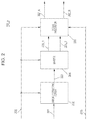
- FIG. 1 is a diagram illustrating an example of a configuration of a transmission apparatus according to an embodiment of the present disclosure
- FIG. 2 is a diagram illustrating an example of a configuration of a signal processor for user #p;
- FIG. 3 is a diagram illustrating an example of a configuration of the signal processor in FIG. 2 ;
- FIG. 4 is a diagram illustrating a different example from FIG. 3 of a configuration of the signal processor in FIG. 2 ;
- FIG. 5 is a diagram illustrating an example of a configuration of a radio section $n in which OFDM is used
- FIG. 6 is a diagram illustrating an example of a configuration of the antenna section in FIG. 1 ;
- FIG. 7 is a diagram illustrating an example of a configuration of a portion related to control information generation for generating the control information symbol signal in FIG. 4 ;
- FIG. 8 is a diagram illustrating an example of the frame configuration of a first baseband signal for user #p;
- FIG. 9 is a diagram illustrating an example of the frame configuration of a second baseband signal for user #p;
- FIG. 10 is a diagram illustrating a different example of the frame configuration of a first baseband signal for user #p;
- FIG. 11 is a diagram illustrating a different example of the frame configuration of a second baseband signal for user #p;
- FIG. 12 is a diagram illustrating an example of a method of arranging symbols with respect to the time axis
- FIG. 13 is a diagram illustrating an example of a method of arranging symbols with respect to the frequency axis
- FIG. 14 is a diagram illustrating an example of arranging symbols with respect to the time-frequency axes
- FIG. 15 is a diagram illustrating an example of arranging symbols with respect to the time axis
- FIG. 16 is a diagram illustrating an example of arranging symbols with respect to the frequency axis
- FIG. 17 is a diagram illustrating an example of arranging symbols with respect to the time-frequency axes
- FIG. 18 is a diagram illustrating a configuration in a case of including an interleaver in a multiplexing signal processor
- FIG. 19 is a diagram illustrating an example of a configuration of a reception apparatus according to the present embodiment.
- FIG. 20 is a diagram illustrating the relationship between the transmission apparatus and the reception apparatus
- FIG. 21 is a diagram illustrating an example of a configuration of the antenna section in FIG. 19 ;
- FIG. 22 is a diagram illustrating an example of a configuration provided together with the transmission apparatus of FIG. 1 in a base station (AP);
- FIG. 23 is a diagram illustrating an example of a configuration provided together with the reception apparatus of FIG. 19 in a terminal;
- FIG. 24 is a diagram illustrating an example of the relationship between a base station (AP) and terminals;
- FIG. 25 is a diagram illustrating an example of the temporal flow of communication between a base station (AP) and terminals;
- FIG. 26 is a diagram illustrating a different example from FIG. 3 of a configuration of the signal processor in FIG. 2 ;
- FIG. 27 is a diagram illustrating an example of communication between a base station (AP) and a terminal #p;
- FIG. 28 is a diagram illustrating an example of data included in receiving ability notification symbols
- FIG. 29 is a diagram illustrating a different example from FIG. 28 of data included in reception capability notification symbols
- FIG. 30 is a diagram illustrating a different example from FIGS. 28 and 29 of data included in reception capability notification symbols;
- FIG. 31 is a diagram illustrating an example of a configuration of a signal processor for user #p;
- FIG. 32 is a diagram illustrating an example of a configuration of a signal processor for user #p;
- FIG. 33 is a diagram illustrating an example of a configuration of a transmission apparatus based on the DVB-NGH standard described in NPL 1;
- FIG. 34 is a diagram illustrating an example of a configuration of a terminal #p on the other end of communication with the base station illustrated in FIG. 24 ;
- FIG. 35 is a diagram illustrating an example of a configuration of the terminal #p illustrated in FIG. 34 ;
- FIG. 36 is a diagram illustrating an example of a frame configuration of a modulated signal of a single stream transmitted using a multi-carrier transmission scheme such as OFDM;
- FIG. 37 is a diagram illustrating an example of a frame configuration of a modulated signal of a single stream transmitted using a single-carrier transmission scheme
- FIG. 38 is a diagram illustrating yet another example of a configuration of the signal processor in FIG. 2 ;
- FIG. 39 is a diagram illustrating yet another example of a configuration of the signal processor in FIG. 2 ;
- FIG. 40 is a diagram illustrating a first example of disposing phase changers upstream and downstream of a weight combiner
- FIG. 41 is a diagram illustrating a second example of disposing phase changers upstream and downstream of a weight combiner
- FIG. 42 is a diagram illustrating a third example of disposing phase changers upstream and downstream of a weight combiner
- FIG. 43 is a diagram illustrating a fourth example of disposing phase changers upstream and downstream of a weight combiner
- FIG. 44 is a diagram illustrating a fifth example of disposing phase changers upstream and downstream of a weight combiner
- FIG. 45 is a diagram illustrating a sixth example of disposing phase changers upstream and downstream of a weight combiner
- FIG. 46 is a diagram illustrating a seventh example of disposing phase changers upstream and downstream of a weight combiner
- FIG. 47 is a diagram illustrating an eighth example of disposing phase changers upstream and downstream of a weight combiner
- FIG. 48 is a diagram illustrating a ninth example of disposing phase changers upstream and downstream of a weight combiner
- FIG. 49 is a diagram illustrating a different example from FIG. 2 of a configuration of a signal processor for user #p;
- FIG. 50A is a diagram illustrating a first example of a state of signal points transmitted in a transmission apparatus that includes the configuration of FIG. 3 ;
- FIG. 50B is a diagram illustrating a first example of a state of signal points of a signal received in a reception apparatus on the other end of communication with a transmission apparatus that includes the configuration of FIG. 3 ;
- FIG. 51A is a diagram illustrating a second example of a state of signal points of a signal transmitted in a transmission apparatus that includes the configuration of FIG. 3 ;
- FIG. 51B is a diagram illustrating a second example of a state of signal points of a signal received in a reception apparatus on the other end of communication with a transmission apparatus that includes FIG. 3 ;
- FIG. 52 is a diagram illustrating a different example from FIG. 1 , of the configuration of a transmission apparatus of a base station (AP);
- FIG. 53 is a diagram illustrating a different example from FIGS. 28, 29, and 30 of data included in reception capability notification symbols;
- FIG. 54 is a diagram illustrating an example of a configuration of a frame
- FIG. 55 is a diagram illustrating an example of carrier groups of modulated signals transmitted by a base station or AP;
- FIG. 56 is a diagram illustrating a different example from FIG. 55 of carrier groups of modulated signals transmitted by a base station or AP;
- FIG. 57 is a diagram illustrating an example of a configuration in which phase changers are added.
- FIG. 58 is a diagram illustrating a first exemplary configuration of the signal processor for user #p in FIGS. 1 and 52 ;
- FIG. 59 is a diagram illustrating a second exemplary configuration of the signal processor for user #p in FIGS. 1 and 52 ;
- FIG. 60 is a diagram illustrating a first example of a configuration included in a control information symbol or the like.
- FIG. 61 is a diagram illustrating a second example of a configuration included in a control information symbol or the like.
- FIG. 62 is a diagram illustrating an example of a configuration of a first signal processor
- FIG. 63 is a diagram illustrating an example of a configuration of a second signal processor
- FIG. 64 is a diagram illustrating an example of the relationship between a base station (AP) and a terminal.
- FIG. 65 is a diagram illustrating a different example from FIG. 1 of the configuration of a transmission apparatus of a base station (AP).
- a transmission method, transmission apparatus, reception method, and reception apparatus of the present embodiment will be described in detail.
- FIG. 1 is a diagram illustrating an example of the configuration of the transmission apparatus in the present embodiment.
- the transmission apparatus illustrated in FIG. 1 is, for example, a base station, an access point, a broadcasting station, or the like.
- the transmission apparatus is an apparatus that generates and transmits multiple modulated signals for transmission to M reception apparatuses (terminals) of user #1 to user #M (where M is an integer equal to 2 or greater).
- the transmission apparatus illustrated in FIG. 1 is provided with a user #1 signal processor 102 _ 1 to a user #M signal processor 102 _M, a multiplexing signal processor 104 , and a radio section $1 ( 106 _ 1 ) to a radio section $N ( 106 _N), an antenna section $1 ( 108 _ 1 ) to an antenna section $N ( 108 _N) (where N is an integer equal to 1 or greater).
- the user #1 signal processor 102 _ 1 accepts a control signal 100 and user #1 data 101 _ 1 as input.
- the user #1 signal processor 102 _ 1 executes signal processing on the basis of information about the transmission method for generating a user #1 modulated signal (for example, an error-correcting coding method (the code rate of the error-correcting code, the code length of the error-correcting code), a modulation scheme, a transmission method (for example, single-stream transmission, multi-stream transmission), and the like) included in the control signal 100 , and generates a user #1 first baseband signal 103 _ 1 _ 1 and/or a user #1 second baseband signal 103 _ 1 _ 2 .
- the user #1 signal processor 102 _ 1 outputs the generated user #1 first baseband signal 103 _ 1 _ 1 and/or user #1 second baseband signal 103 _ 1 _ 2 to the multiplexing signal processor 104 .
- the user #1 signal processor 102 _ 1 In the case in which information indicating that multi-stream transmission has been selected is included in the control signal 100 , the user #1 signal processor 102 _ 1 generates the user #1 first baseband signal 103 _ 1 _ 1 and the user #1 second baseband signal 103 _ 1 _ 2 . In the case in which information indicating that single-stream transmission has been selected is included in the control signal 100 , the user #1 signal processor 102 _ 1 generates the user #1 first baseband signal 103 _ 1 _ 1 .
- the user #2 signal processor 102 _ 2 accepts the control signal 100 and user #2 data 101 _ 2 as input.
- the user #2 signal processor 102 _ 2 executes signal processing on the basis of information about the transmission method for generating a user #2 modulated signal (for example, an error-correcting coding method (the code rate of the error-correcting code, the code length of the error-correcting code), a modulation scheme, a transmission method (for example, single-stream transmission, multi-stream transmission), and the like) included in the control signal 100 , and generates a user #2 first baseband signal 103 _ 2 _ 1 and/or a user #2 second baseband signal 103 _ 2 _ 2 .
- the user #2 signal processor 102 _ 2 outputs the generated user #2 first baseband signal 103 _ 2 _ 1 and/or user #2 second baseband signal 103 _ 2 _ 2 to the multiplexing signal processor 104 .
- the user #2 signal processor 102 _ 2 In the case in which information indicating that multi-stream transmission has been selected is included in the control signal 100 , the user #2 signal processor 102 _ 2 generates the user #2 first baseband signal 103 _ 2 _ 1 and the user #2 second baseband signal 103 _ 2 _ 2 . In the case in which information indicating that single-stream transmission has been selected is included in the control signal 100 , the user #2 signal processor 102 _ 2 generates the user #2 first baseband signal 103 _ 2 _ 1 .
- the user #M signal processor 102 _M accepts the control signal 100 and user #2 data 101 _M as input.
- the user #M signal processor 102 _M executes signal processing on the basis of information about the transmission method for generating a user #M modulated signal (for example, an error-correcting coding method (the code rate of the error-correcting code, the code length of the error-correcting code), a modulation scheme, a transmission method (for example, single-stream transmission, multi-stream transmission), and the like) included in the control signal 100 , and generates a user #M first baseband signal 103 _M_ 1 and/or a user #M second baseband signal 103 _M_ 2 .
- the user #M signal processor 102 _M outputs the generated user #M first baseband signal 103 _M_ 1 and/or user #M second baseband signal 103 _M_ 2 to the multiplexing signal processor 104 .
- the user #M signal processor 102 _M In the case in which information indicating that multi-stream transmission has been selected is included in the control signal 100 , the user #M signal processor 102 _M generates the user #M first baseband signal 103 _M_ 1 and the user #M second baseband signal 103 _M_ 2 . In the case in which information indicating that single-stream transmission has been selected is included in the control signal 100 , the user #M signal processor 102 _M generates the user #M first baseband signal 103 _M_ 1 .
- a user #p signal processor 102 _ p (where p is an integer from 1 to M) accepts the control signal 100 and user #p data 101 _ p as input.
- the user #p signal processor 102 _ p executes signal processing on the basis of information about the transmission method for generating a user #p modulated signal (for example, an error-correcting coding method (the code rate of the error-correcting code, the code length of the error-correcting code), a modulation scheme, a transmission method (for example, single-stream transmission, multi-stream transmission), and the like) included in the control signal 100 , and generates a user #p first baseband signal 103 _ p _ 1 and/or a user #p second baseband signal 103 _ p _ 2 .
- the user #p signal processor 102 _ p outputs the generated user #p first baseband signal 103 _ p _ 1 and/or user #p second baseband signal 103 _ p _ 2 to the multiplex
- the user #p signal processor 102 _ p generates the user #p first baseband signal 103 _ p _ 1 and the user #p second baseband signal 103 _ p _ 2 .
- the user #p signal processor 102 _ p generates the user #p first baseband signal 103 _ p _ 1 .
- each from the user #1 signal processor 102 _ 1 to the user #M signal processor 102 _M will be described later by taking the configuration of the user #p signal processor as an example.
- control signal 100 includes information indicating whether multi-stream transmission or single-stream transmission has been selected with respect to each from the user #1 signal processor 102 _ 1 to the user #M signal processor 102 _M.
- the multiplexing signal processor 104 accepts the control signal 100 , the user #1 first baseband signal 103 _ 1 _ 1 , the user #1 second baseband signal 103 _ 1 _ 2 , the user #2 first baseband signal 103 _ 2 _ 1 , the user #2 second baseband signal 1032 _ 2 _ 2 , . . . , the user #M first baseband signal 103 _M_ 1 , the user #M second baseband signal 103 _M_ 2 , and a (common) reference signal 199 as input.
- the multiplexing signal processor 104 performs multiplexing signal processing on the basis of the control signal 100 , and generates a multiplexed signal $1 baseband signal 105 _ 1 to a multiplexed signal $N baseband signal 105 N (where N is an integer equal to 1 or greater).
- the multiplexing signal processor 104 outputs the generated multiplexed signal $1 baseband signal 105 _ 1 to the multiplexed signal $N baseband signal 105 _N to corresponding radio sections (radio section $1 to radio section $N).
- the (common) reference signal 199 is a signal transmitted from the transmission apparatus for the reception apparatus to estimate the propagation environment.
- the (common) reference signal 199 is inserted into the baseband signal of each user. Note that the multiplexing signal processing will be described later.
- the radio section $1 ( 106 _ 1 ) accepts the control signal 100 and the multiplexed signal $1 baseband signal 105 _ 1 as input. On the basis of the control signal 100 , the radio section $1 ( 106 _ 1 ) executes processes such as frequency conversion and amplification, and outputs a transmission signal 107 _ 1 to the antenna section $1 ( 108 _ 1 ).
- the antenna section $1 ( 108 _ 1 ) accepts the control signal 100 and the transmission signal 107 _ 1 as input.
- the antenna section $1 ( 108 _ 1 ) processes the transmission signal 107 _ 1 on the basis of the control signal 100 .
- the control signal 100 may also not be present as input.
- the transmission signal 107 _ 1 is output as a radio wave from the antenna section $1 ( 108 _ 1 ).
- the radio section $2 ( 106 _ 2 ) accepts the control signal 100 and the multiplexed signal $2 baseband signal 105 _ 2 as input. On the basis of the control signal 100 , the radio section $2 ( 106 _ 2 ) executes processes such as frequency conversion and amplification, and outputs a transmission signal 107 _ 2 to the antenna section $2 ( 108 _ 2 ).
- the antenna section $2 ( 108 _ 2 ) accepts the control signal 100 and the transmission signal 107 _ 2 as input.
- the antenna section $2 ( 108 _ 2 ) processes the transmission signal 107 _ 2 on the basis of the control signal 100 .
- the control signal 100 may also not be present as input.
- the transmission signal 107 _ 2 is output as a radio wave from the antenna section $2 ( 108 _ 2 ).
- the radio section $N ( 106 _N) accepts the control signal 100 and the multiplexed signal $N baseband signal 105 _N as input. On the basis of the control signal 100 , the radio section $N ( 106 _N) executes processes such as frequency conversion and amplification, and outputs a transmission signal 107 _N to the antenna section $N ( 108 _N).
- the antenna section $N ( 108 _N) accepts the control signal 100 and the transmission signal 107 _N as input.
- the antenna section $N ( 108 _N) processes the transmission signal 107 _N on the basis of the control signal 100 .
- the control signal 100 may also not be present as input.
- the transmission signal 107 _N is output as a radio wave from the antenna section $N ( 108 _N).
- the radio section $n ( 106 _ n ) (where n is an integer from 1 to N) accepts the control signal 100 and the multiplexed signal $n baseband signal 105 _ n as input. On the basis of the control signal 100 , the radio section $n ( 106 _ n ) executes processes such as frequency conversion and amplification, and outputs a transmission signal 107 _ n to the antenna section $n ( 108 _ n ).
- the antenna section $n ( 108 _ n ) accepts the control signal 100 and the transmission signal 107 _ n as input.
- the antenna section $n ( 108 _ n ) processes the transmission signal 107 _ n on the basis of the control signal 100 .
- the control signal 100 may also not be present as input.
- the transmission signal 107 _ n is output as a radio wave from the antenna section $n ( 108 _ n ).
- the control signal 100 may be generated on the basis of information transmitted to the transmission apparatus in FIG. 1 by the reception apparatus on the other end of communication in FIG. 1 , or the transmission apparatus in FIG. 1 may be provided with an input section, and the control signal 100 may be generated on the basis of information input from the input section.
- the transmission apparatus in FIG. 1 not all from the user #1 signal processor ( 102 _ 1 ) to the user #M signal processor ( 102 _M) may be operating. All may be operating, or some may be operating. In other words, the number of users that the transmission apparatus is communicating with is from 1 to M. The number of communication peers (users) to which the transmission apparatus in FIG. 1 transmits a modulated signal is from 1 to M.
- radio section $1 ( 106 _ 1 ) to the radio section $N ( 106 _N) may be operating. All may be operating, or some may be operating. Also, not all from the antenna section $1 ( 108 _ 1 ) to the antenna section $N ( 108 _N) may be operating. All may be operating, or some may be operating.
- the transmission apparatus in FIG. 1 is able to transmit the modulated signals (baseband signals) of multiple users using identical times and identical frequencies (bands) by using multiple antennas.
- the transmission apparatus in FIG. 1 is able to transmit the user #1 first baseband signal 103 _ 1 _ 1 , the user #1 second baseband signal 103 _ 1 _ 2 , the user #2 first baseband signal 103 _ 2 _ 1 , and the user #2 second baseband signal 103 _ 2 _ 2 using identical times and identical frequencies (bands). Also, the transmission apparatus in FIG. 1 is able to transmit the user #1 first baseband signal 103 _ 1 _ 1 , the user #1 second baseband signal 103 _ 1 _ 2 , and the user #2 first baseband signal 103 _ 2 _ 1 using identical times and identical frequencies (bands). Note that the combinations of modulated signals (baseband signals) of multiple users to which the transmission apparatus in FIG. 1 transmits are not limited to these examples.
- FIG. 2 is a diagram illustrating an example of a configuration of the user #p signal processor 102 _ p.
- the user #p signal processor 102 _ p is provided with an error-correcting coder 202 , a mapper 204 , and a signal processor 206 .
- the error-correcting coder 202 accepts user #p data 201 and a control signal 200 as input.
- the control signal 200 corresponds to the control signal 100 in FIG. 1
- the user #p data 201 corresponds to the user #p data 101 _ p in FIG. 1 .
- the error-correcting coder 202 executes error-correcting coding on the basis of information related to error-correcting coding (for example, error-correcting code information, the code length (block length), and the code rate) included in the control signal 200 , and outputs user #p coded data 203 to the mapper 204 .
- information related to error-correcting coding for example, error-correcting code information, the code length (block length), and the code rate
- the error-correcting coder 202 may also be provided with an interleaver. In the case of being provided with an interleaver, the error-correcting coder 202 sorts the data after coding, and outputs user #p coded data 203 .
- the mapper 204 accepts the user #p coded data 203 and the control signal 200 as input.
- the mapper 204 executes mapping corresponding to the modulation scheme on the basis of information about the modulation scheme included in the control signal 200 , and generates a user #p mapped signal (baseband signal) 205 _ 1 and/or mapped signal (baseband signal) 205 _ 2 .
- the mapper 204 outputs the generated user #p mapped signal (baseband signal) 205 _ 1 and/or mapped signal (baseband signal) 205 _ 2 to the signal processor 206 .
- the mapper 204 divides the user #p coded data 203 into a first sequence and a second sequence. Subsequently, the mapper 204 uses the first sequence to generate a user #p mapped signal 205 _ 1 , and uses the second sequence to generate a user #p mapped signal 205 _ 2 . At this time, the first sequence and the second sequence are assumed to be different. However, it is possible to carry out the above similarly even if the first sequence and the second sequence are the same.
- the mapper 204 may divide the user #p coded data 203 into three or more sequences, use each sequence to execute mapping, and generate three or more mapped signals.
- the three or more sequences may be different from each other, but some or all of the three or more sequences may also be the same sequences.
- the user #p coded data 203 is treated as a single sequence to generate the user #p mapped signal 205 _ 1 .
- the signal processor 206 accepts the user #p mapped signal 205 _ 1 and/or the user #p mapped signal 205 _ 2 , as well as a signal group 210 and the control signal 200 as input. On the basis of the control signal 200 , the signal processor 206 executes signal processing, and outputs user #p signal-processed signals 207 _A and 207 _B.
- the user #p signal-processed signal 207 _A corresponds to the user #p first baseband signal 103 _ p _ 1 in FIG. 1
- the user #p signal-processed signal 207 _B corresponds to the user #p second baseband signal 103 _ p _ 2 in FIG. 1 .
- the user #p signal-processed signal 207 _A is designated up1(i)
- the user #p signal-processed signal 207 _B is designated up2(i).
- i is taken to be the symbol number.
- i is an integer equal to 0 or greater.
- FIG. 3 is a diagram illustrating an example of the configuration of the signal processor 206 in FIG. 2 .
- the signal processor 206 is provided with a weight combiner 303 , a phase changer 305 B, an inserter 307 A, an inserter 307 B, and a phase changer 309 B.
- FIG. 3 illustrates a case in which the mapper 204 in FIG. 2 generates the user #p mapped signal 205 _ 1 and the user #p mapped signal 205 _ 2 on the basis of information indicating that multi-stream transmission has been selected.
- the weight combiner 303 (precoder) 303 accepts a user #p mapped signal 301 A, a user #p mapped signal 301 B, and a control signal 300 as input.
- the user #p mapped signal 301 A corresponds to the user #p mapped signal 205 _ 1 in FIG. 2
- the user #p mapped signal 301 B corresponds to the user #p mapped signal 205 _ 2 in FIG. 2
- the control signal 300 corresponds to the control signal 200 in FIG. 2 .
- the weight combiner 303 executes weight combining (precoding), and generates a user #p weighted signal 304 A and a user #p weighted signal 304 B.
- the weight combiner 303 outputs the user #p weighted signal 304 A to the inserter 307 A.
- the weight combiner 303 outputs the user #p weighted signal 304 B to the phase changer 305 B.
- the user #p mapped signal 301 A is designated sp1(t)
- the user #p mapped signal 301 B is designated sp2(t)
- the user #p weighted signal 304 A is designated zp1(t)
- the user #p weighted signal 304 B is designated zp2′(t).
- t is taken to be time as an example.
- sp1(t), sp2(t), zp1(t), and zp2′(t) are taken to be defined as complex numbers. Consequently, sp1(t), sp2(t), zp1(t), and zp2′(t) may also be real numbers.
- the weight combiner 303 executes computation based on the following Formula (1).
- a, b, c, and d are defined as complex numbers. However, a, b, c, and d may also be real numbers. Note that i is taken to be the symbol number.
- the phase changer 305 B accepts the weighted signal 304 B and the control signal 300 as input. On the basis of the control signal 300 , the phase changer 305 B changes the phase of the weighted signal 304 B, and outputs a phase-changed signal 306 B to the inserter 307 B.
- the phase-changed signal 306 B is designated zp2(t).
- zp2(t) is taken to be defined as a complex number. Note that zp2(t) may also be a real number.
- phase changer 305 B The specific operation of the phase changer 305 B will be described.
- i is taken to be the symbol number (where i is an integer equal to 0 or greater).
- phase changer 305 B sets the value of the phase change expressed as yp(i) like the following Formula (2).
- yp ⁇ ( i ) e j ⁇ ⁇ 2 ⁇ ⁇ ⁇ i Np ( 2 )
- j is the imaginary unit.
- Np is an integer equal to 2 or greater, and indicates the period of the phase change. If Np is set to an odd number equal to 3 or greater, there is a possibility that the received signal quality of the data will improve.
- zp1(i) and zp2(i) may be expressed as the following Formula (3).
- the phase change value yp(i) is not limited to Formula (2), and for example, a method that changes the phase periodically or regularly is conceivable.
- the matrix used in the computation of the weight combiner 303 illustrated in Formula (1) and Formula (3) will be described.
- the matrix used in the computation of the weight combiner 303 is expressed as Fp, as illustrated in the following Formula (4).
- Fp ( ⁇ ⁇ cos ⁇ ⁇ ⁇ ⁇ ⁇ ⁇ sin ⁇ ⁇ ⁇ ⁇ sin ⁇ ⁇ ⁇ - ⁇ ⁇ cos ⁇ ⁇ ⁇ ) ( 13 )
- Fp ( cos ⁇ ⁇ ⁇ sin ⁇ ⁇ ⁇ sin ⁇ ⁇ ⁇ - cos ⁇ ⁇ ⁇ ) ( 14 )
- Fp ( ⁇ ⁇ cos ⁇ ⁇ ⁇ - ⁇ ⁇ sin ⁇ ⁇ ⁇ ⁇ sin ⁇ ⁇ ⁇ ⁇ cos ⁇ ⁇ ⁇ ) ( 15 )
- Fp ( cos ⁇ ⁇ ⁇ - sin ⁇ ⁇ ⁇ sin ⁇ ⁇ ⁇ cos ⁇ ⁇ ⁇ ) ( 16 )
- Fp ( ⁇ ⁇ sin ⁇ ⁇ ⁇ - ⁇ ⁇ cos ⁇ ⁇ ⁇ ⁇ cos ⁇ ⁇ ⁇ ⁇ ) ( 16 )
- Fp ( ⁇
- ⁇ is a real, fixed value. Note that ⁇ may also not be a fixed value. Also, ⁇ may be a real number or an imaginary number. Also, ⁇ may be a real number or an imaginary number. However, ⁇ is not 0 (zero). Also, ⁇ is not 0 (zero). Also, ⁇ 11 and ⁇ 21 are real numbers.
- the weight combiner 303 in FIG. 3 does not perform signal processing on the mapped signals 301 A and 301 B, and instead outputs the mapped signal 301 A as a weighted signal 304 A, and outputs the mapped signal 301 B as a weighted signal 304 B.
- the weight combiner 303 may also not exist, and in the case in which the weight combiner 303 exists, the weight combiner 303 may be controlled by the control signal 300 to perform weight combining or not perform weight combining.
- the inserter 307 A accepts the weighted signal 304 A, a pilot symbol signal (pa(t)) ( 351 A), a preamble signal 352 , a control information symbol signal 353 , and the control signal 300 as input. On the basis of information about the frame configuration included in the control signal 300 , the inserter 307 A outputs a baseband signal 308 A based on the frame configuration to the multiplexing signal processor 104 .
- the inserter 307 B accepts the phase-changed signal 306 B, a pilot symbol signal (pb(t)) ( 351 B), the preamble signal 352 , the control information symbol signal 353 , and the control signal 300 as input. On the basis of information about the frame configuration included in the control signal 300 , the inserter 307 B outputs a baseband signal 308 B based on the frame configuration to the phase changer 309 B.
- control information for generating the control information symbol signal 353 and the frame configuration in the transmission apparatus used in the inserter 307 B will be described later.
- the phase changer 309 B accepts the baseband signal 308 B and the control signal 300 as input.
- the phase changer 309 B changes the phase of the baseband signal 308 B on the basis of the control signal 300 , and outputs a phase-changed signal 310 B to the multiplexing signal processor 104 .
- the baseband signal 308 B is taken to be a function of the symbol number i, and is expressed as xp′(i).
- the operation of the phase changer 309 B may be cyclic delay diversity (CDD) (cyclic shift diversity (CSD)) described in NPL 2 and NPL 3. Additionally, a characteristic of the phase changer 309 B is that the phase change is executed on symbols existing in the frequency axis direction. The phase changer 309 B performs phase change on data symbols, pilot symbols, control information symbols, and the like.
- CDD cyclic delay diversity
- CSS cyclic shift diversity
- FIG. 3 illustrates the signal processor 206 provided with the phase changer 309 B
- the phase changer 309 B may also not be included in the signal processor 206 .
- whether or not the phase changer 309 B operates may be switched.
- the inserter 307 B outputs the baseband signal 308 B to the multiplexing signal processor 104 of FIG. 1 . In this way, in FIG.
- the baseband signal 308 B becomes the output signal to the multiplexing signal processor 104 instead of the phase-changed signal 310 B.
- the phase changer 309 B does not operate will be described.
- the weight combiner 303 does not perform signal processing for weight combining on the mapped signals 301 A and 301 B, and instead outputs the mapped signal 301 A as the weighted signal 304 A, and outputs the mapped signal 301 B as the weighted signal 304 B.
- the weight combiner 303 controls the switching between a process (i) and a process (ii), namely, (i) a process of performing signal processing corresponding to weight combining to generate and output the weighted signals 304 A and 304 B, and (ii) a process of not executing signal processing for weight combining, and instead outputting the mapped signal 301 A as the weighted signal 304 A, and outputting the mapped signal 301 B as the weighted signal 304 B.
- the signal processor 206 of FIG. 2 may also not be provided with the weight combiner 303 .
- the mapper 204 of FIG. 2 generates the signals of two sequences when multi-stream transmission is selected for user #p.
- the weight combiner 303 , the phase changer 305 B, and the inserter 307 B may not operate, and the user #p mapped signal 301 A may be input into the inserter 307 A without being weighted.
- the user #p signal processor 102 _ p in FIG. 1 may not be provided with the weight combiner 303 , the phase changer 305 B, and the inserter 307 B among the configuration of FIG. 3 .
- the above describes a case in which the mapper 204 of FIG. 2 generates the signals of two sequences when multi-stream transmission is selected for user #p.
- the mapper 204 of FIG. 2 may also generate the signals of three or more sequences when multi-stream transmission is selected for user #p.
- the weight combiner 303 of FIG. 3 executes weight combining using a precoding matrix that depends on the number of input signals, for example, and outputs three or more weighted signals. Note that the number of signals input into the weight combiner 303 of FIG. 3 and the number of signals output from the weight combiner 303 do not have to be the same. In other words, the precoding matrix used by the weight combiner 303 does not have to be a square matrix.
- the signal processor 102 _ p may change the phase of all or some of the three or more weighted signals.
- phase change does not have to be executed on all of the three or more weighted signals which are output.
- FIG. 4 is a diagram illustrating a different example from FIG. 3 of the configuration of the signal processor 206 in FIG. 2 .
- parts of the configuration which are similar to FIG. 3 are denoted with the same numbers. Note that a description will be omitted herein for the parts of the configuration which are similar to FIG. 3 .
- the signal processor 206 of FIG. 4 is a configuration obtained by adding a coefficient multiplier 401 A and a coefficient multiplier 401 B to the signal processor 206 of FIG. 3 .
- the coefficient multiplier 401 A accepts the mapped signal 301 A (sp1(i)) and the control signal 300 as input. On the basis of the control signal 300 , the coefficient multiplier 401 A multiplies the mapped signal 301 A (sp1(i)) by a coefficient, and outputs a coefficient-multiplied signal 402 A to the weight combiner 303 . Note that, provided that the coefficient is up, the coefficient-multiplied signal 402 A is expressed as up ⁇ sp1(i). Herein, up may be a real number or a complex number. However, up is not 0 (zero).
- the coefficient multiplier 401 A does not multiply the mapped signal 301 A (sp1(i)) by the coefficient, and outputs the mapped signal 301 A (sp1(i)) as the coefficient-multiplied signal 402 A.
- the coefficient multiplier 401 B accepts the mapped signal 301 B (sp2(i)) and the control signal 300 as input. On the basis of the control signal 300 , the coefficient multiplier 401 B multiplies the mapped signal 301 B (sp2(i)) by a coefficient, and outputs a coefficient-multiplied signal 402 B to the weight combiner 303 .
- the coefficient-multiplied signal 402 B is expressed as vp ⁇ sp2(i).
- vp may be a real number or a complex number. However, vp is not 0 (zero).
- the coefficient multiplier 401 B does not multiply the mapped signal 301 B (sp2(i)) by the coefficient, and outputs the mapped signal 301 B (sp2(i)) as the coefficient-multiplied signal 402 B.
- the weighted signal 304 A (zp1(i)) output from the weight combiner 303 and the phase-changed signal 306 B (zp2(i)) output from the phase changer 305 B are expressed by the following Formula (37) using the coefficient up of the coefficient multiplier 401 A, the coefficient vp of the coefficient multiplier 401 B, and Formula (3).
- FIGS. 1 to 4 and Formulas (1) to (37) are cited as an example to describe a method by which the user #p signal processor 102 _ p generates symbols (for example, zp1(i), zp2(i)).
- the generated symbols may be arranged in the time axis direction.
- the generated symbols may also be arranged in the frequency axis direction, or in the time-frequency directions.
- the generated symbols may be interleaved (that is, the symbols may be sorted) and arranged in the time axis direction, the frequency axis direction, or the time-frequency axis directions.
- Symbol arranging is executed in the user #p signal processor 102 _ p by the error-correcting coder 202 and/or the mapper 204 illustrated in FIG. 2 , for example.
- the transmission apparatus illustrated in FIG. 1 transmits zp1(i) and zp2(i) having the same symbol number i using identical times and identical frequencies (identical frequency bands).
- the user #1 signal processor 102 _ 1 uses Formula (3) or Formula (37) to generate the user #1 baseband signal 103 _ 1 _ 1 and the user #1 baseband signal 103 _ 1 _ 2 .
- the user #2 signal processor 102 _ 2 uses Formula (3) or Formula (37) to generate the user #2 baseband signal 103 _ 2 _ 1 and the user #2 baseband signal 103 _ 2 _ 2 .
- the user #M signal processor 102 _M generates the user #M baseband signal 103 _M_ 1 and the user #M baseband signal 103 _M_ 2 .
- the precoding matrix Fp made up of a, b, c, and d in Formula (3) and Formula (37) and/or the phase change value yp(i) are set depending on the value of p.
- the precoding matrix Fp and/or the phase change value yp(i) used in the user #p signal processor 102 _ p are set respectively depending on the value of p, or in other words, for each user.
- Information for setting the precoding matrix Fp and/or the phase change value yp(i) is included in the control signal.
- precoding and phase change may not be applied to all from the user #1 signal processor 102 _ 1 to the user #M signal processor 102 _M in FIG. 1 .
- a signal processor for which phase change is not executed may exist among the user #1 signal processor 102 _ 1 to the user #M signal processor 102 _M.
- a signal processor that generates a single baseband signal may exist among the user #1 signal processor 102 _ 1 to the user #M signal processor 102 _M.
- the phase changer 305 B does not execute phase change, or in other words, the phase changer 305 B does not change the phase of the input weighted signal 304 B, and outputs the weighted signal 304 B as 306 B.
- the multiplexing signal process (weight combining process) in the multiplexing signal processor 104 of FIG. 1 will be described specifically.
- the user #p first baseband signal 103 _ p _ 1 and the user #p second baseband signal 103 _ p _ 2 output by the user #p signal processor 102 _ p (where p is an integer from 1 to M) in FIG. 1 are expressed as zp1(i) and zp2(i) on the basis of Formula (3).
- i is taken to be the symbol number.
- i is treated as being an integer equal to 0 or greater.
- the signals b ⁇ 2p ⁇ 1 ⁇ (i) and b ⁇ 2p ⁇ (i) are expressed as in the following Formulas (38) and (39).
- b ⁇ 2 p ⁇ 1 ⁇ ( i ) zp 1( i ) (38)
- b ⁇ 2 p ⁇ ( i ) zp 2( i ) (39)
- the user #1 first baseband signal 103 _ 1 _ 1 and the user #1 second baseband signal 103 _ 1 _ 2 are expressed as b ⁇ 1 ⁇ (i) and b ⁇ 2 ⁇ (i), respectively.
- the output signals are expressed as b ⁇ 1 ⁇ (i) to b ⁇ 2M ⁇ (i).
- the output of the multiplexing signal processor 104 namely the multiplexed signal $1 baseband signal 105 _ 1 to the multiplexed signal $N baseband signal 105 _N, are denoted v1(i) to vN(i), respectively.
- the multiplexed signal $n baseband signal 105 _ n becomes vn(i) (where n is an integer from 1 to N).
- vn(i) may be expressed by the following Formula (40).
- ⁇ n ⁇ k ⁇ is the weighted coefficient of multiplexing, and may be defined as a complex number.
- ⁇ (n)(k) ⁇ may be a real number.
- ⁇ (n)(k) ⁇ is decided by feedback information of each terminal.
- the user #p signal processor 102 _ p in FIG. 1 outputs one or two modulated signals is described as an example, but the configuration is not limited thereto, and the user #p signal processor 102 _ p may also output three or more modulated signals.
- the process of the multiplexing signal processor 104 must be expressed by a different formula from Formula (40).
- the radio section $1 ( 106 _ 1 ) to the radio section $N ( 106 _N) in FIG. 1 execute processes such as frequency conversion and amplification on a signal input into each, and generate a transmission signal.
- a single-carrier scheme or a multi-carrier scheme such as orthogonal frequency-division multiplexing (OFDM) may be used.
- OFDM orthogonal frequency-division multiplexing
- FIG. 5 is a diagram illustrating an example of a configuration of the radio section $n ( 106 _ n ) in which OFDM is used.
- the radio section $n ( 106 _ n ) is provided with a serial-parallel converter 502 , an inverse Fourier transform section 504 , and a processor 506 .
- the serial-parallel converter 502 accepts a signal 501 and a control signal 500 as input. On the basis of the control signal 500 , the serial-parallel converter 502 executes serial-parallel conversion on the input signal 501 , and outputs a serial-parallel converted signal 503 to the inverse Fourier transform section 504 .
- the signal 501 corresponds to the multiplexed signal $n baseband signal 105 _ n in FIG. 1
- the control signal 500 corresponds to the control signal 100 in FIG. 1 .
- the inverse Fourier transform section 504 accepts the serial-parallel converted signal 503 and the control signal 500 as input. On the basis of the control signal 500 , the inverse Fourier transform section 504 performs an inverse Fourier transform (for example, the inverse fast Fourier transform (IFFT)), and outputs an inverse Fourier transformed signal 505 to the processor 506 .
- an inverse Fourier transform for example, the inverse fast Fourier transform (IFFT)
- the processor 506 accepts the inverse Fourier transformed signal 505 and the control signal 500 as input. On the basis of the control signal 500 , the processor 506 performs processes such as frequency conversion and amplification, and outputs a modulated signal 507 to the antenna section $n ( 108 _ n ). The modulated signal 507 output from the processor 506 corresponds to the transmission signal 107 _ n in FIG. 1 .
- FIG. 6 is a diagram illustrating an example of the configuration of the antenna sections (antenna section $1 ( 108 _ 1 ) to antenna section $N ( 108 _N)) in FIG. 1 .
- the configuration in FIG. 6 is an example in which the antenna section $1 ( 108 _ 1 ) to the antenna section $N ( 108 _N) are configured with four antennas.
- An antenna section is provided with a distributor 902 , multipliers 904 _ 1 to 904 _ 4 , and antennas 906 _ 1 to 906 _ 4 .
- the distributor 902 accepts a transmission signal 901 as input.
- the distributor 902 distributes the transmission signal 901 , and outputs transmission signals 903 _ 1 , 903 _ 2 , 903 _ 3 , and 903 _ 4 to the corresponding multipliers (multiplier 904 _ 1 to multiplier 904 _ 4 ).
- the transmission signal 901 corresponds to the transmission signal 107 _ 1 in FIG. 1 .
- the transmission signal 901 corresponds to the transmission signal 107 _ 2 in FIG. 1 .
- the transmission signal 901 corresponds to the transmission signal 107 _N in FIG. 1 .
- the multiplier 904 _ 1 accepts the transmission signal 903 _ 1 and a control signal 900 as input. On the basis of information about a multiplication coefficient included in the control signal 900 , the multiplier 904 _ 1 multiplies the transmission signal 903 _ 1 by the multiplication coefficient, and outputs a multiplied signal 905 _ 1 to the antenna 906 _ 1 .
- the multiplied signal 905 _ 1 is output from the antenna 906 _ 1 as a radio wave.
- the transmission signal 903 _ 1 is Tx1(t) (where t is time), and the multiplication coefficient is W1, the multiplied signal 905 _ 1 is expressed as Tx1(t) ⁇ W1.
- W1 may be defined as a complex number, and consequently, may also be a real number.
- the multiplier 904 _ 2 accepts the transmission signal 903 _ 2 and the control signal 900 as input. On the basis of information about a multiplication coefficient included in the control signal 900 , the multiplier 904 _ 2 multiplies the transmission signal 903 _ 2 by the multiplication coefficient, and outputs a multiplied signal 905 _ 2 to the antenna 906 _ 2 .
- the multiplied signal 905 _ 2 is output from the antenna 906 _ 2 as a radio wave.
- the transmission signal 903 _ 2 is Tx2(t), and the multiplication coefficient is W2, the multiplied signal 905 _ 2 is expressed as Tx2(t) ⁇ W2.
- W2 may be defined as a complex number, and consequently, may also be a real number.
- the multiplier 904 _ 3 accepts the transmission signal 903 _ 3 and the control signal 900 as input. On the basis of information about a multiplication coefficient included in the control signal 900 , the multiplier 904 _ 3 multiplies the transmission signal 903 _ 3 by the multiplication coefficient, and outputs a multiplied signal 905 _ 3 to the antenna 906 _ 3 .
- the multiplied signal 905 _ 3 is output from the antenna 906 _ 3 as a radio wave.
- the transmission signal 903 _ 3 is Tx3(t), and the multiplication coefficient is W3, the multiplied signal 905 _ 3 is expressed as Tx3(t) ⁇ W3.
- W3 may be defined as a complex number, and consequently, may also be a real number.
- the multiplier 904 _ 4 accepts the transmission signal 903 _ 4 and the control signal 900 as input. On the basis of information about a multiplication coefficient included in the control signal 900 , the multiplier 904 _ 4 multiplies the transmission signal 903 _ 4 by the multiplication coefficient, and outputs a multiplied signal 905 _ 4 to the antenna 906 _ 4 .
- the multiplied signal 905 _ 4 is output from the antenna 906 _ 4 as a radio wave.
- the transmission signal 903 _ 4 is Tx4(t), and the multiplication coefficient is W4, the multiplied signal 905 _ 4 is expressed as Tx4(t) ⁇ W4.
- W4 may be defined as a complex number, and consequently, may also be a real number.
- the absolute value of W1, the absolute value of W2, the absolute value of W3, and the absolute value of W4 may be equal”. This case corresponds to executing a phase change. Obviously, the absolute value of W1, the absolute value of W2, the absolute value of W3, and the absolute value of W4 may also not be equal.
- each antenna section is configured with four antennas (and four multipliers), but the number of antennas is not limited to four, and it is sufficient for each antenna section to include one or more antennas.
- each from the antenna section $1 ( 108 _ 1 ) to the antenna section $N ( 108 _N) in FIG. 1 may be configured to include a single antenna or multiple antennas.
- FIG. 7 is a diagram illustrating an example of a configuration of a portion related to control information generation for generating the control information symbol signal 353 in FIGS. 3 and 4 .
- a control information mapper 802 accepts control information-related data 801 and a control signal 800 as input.
- the control information mapper 802 uses a modulation scheme based on the control signal 800 to map the control information-related data 801 , and outputs a control information mapped signal 803 .
- the control information mapped signal 803 corresponds to the control information symbol signal 353 in FIGS. 3 and 4 .
- the frame configuration illustrates the arrangement of data symbols, pilot symbols, and other symbols to be transmitted.
- Information about the frame configuration is included in the control signal 300 (see FIGS. 3 and 4 ).
- the inserter 307 A and the inserter 307 B illustrated in FIGS. 3 and 4 respectively generate the baseband signal 308 A and the baseband signal 308 B based on the frame configuration.
- the following takes, as an example, a case in which a multi-carrier transmission scheme such as OFDM is used, and in the user #p signal processor 102 _ p , the inserter 307 A outputs the user #p first baseband signal 103 _ p _ 1 as the baseband signal 308 A, and the baseband signal 308 B outputs the user #p second baseband signal 103 _ p _ 2 as the baseband signal 308 B.
- the frame configuration in this case will be described by taking the user #p first baseband signal 103 _ p _ 1 and the user #p second baseband signal 103 _ p _ 2 as an example.
- FIG. 8 is a diagram illustrating an example of the frame configuration of the user #p first baseband signal 103 _ p _ 1 .
- the horizontal axis indicates frequency (carrier), while the vertical axis indicates time. Since a multi-carrier transmission scheme such as OFDM is used, symbols exist in the carrier direction.
- FIG. 8 illustrates, as one example, symbols from carrier 1 to carrier 36. Also, FIG. 8 illustrates symbols from time 1 to time 11.
- 601 illustrates pilot symbols (the pilot symbol signal 351 A (corresponding to pa(t)) in FIGS. 3 and 4 ), 602 illustrates data symbols, and 603 illustrates other symbols.
- the pilot symbols are phase-shift keying (PSK) symbols, for example, and are symbols by which the reception apparatus that receives the frame executes channel estimation (estimation of channel variation) and estimation of the frequency offset/phase variation.
- PSK phase-shift keying
- the transmission apparatus in FIG. 1 and the reception apparatus that receives a signal with the frame configuration of FIG. 8 preferably share the pilot symbol transmission method in common.
- the user #p mapped signal 205 _ 1 is designated “stream #1”, and the user #p mapped signal 205 _ 2 is designated “stream #2”. Note that the same also applies to the description hereinafter.
- the data symbols 602 are symbols corresponding to the data symbols included in the baseband signal 207 _A generated in FIG. 2 . Consequently, the data symbols 602 are any of “symbols including both the symbols of ‘stream #1’ and the symbols of ‘stream #2’”, or “the symbols of ‘stream #1’”, or “the symbols of ‘stream #2’”. This is decided by the configuration of the precoding matrix used by the weight combiner 303 in FIG. 3 . In other words, the data symbols 602 correspond to the weighted signal 304 A (zp1(i)).
- the other symbols 603 are taken to be symbols corresponding to the preamble signal 352 and the control information symbol signal 353 in FIGS. 3 and 4 .
- the other symbols may also include symbols other than preamble and control information symbols.
- the preamble may transmit data (for control), or includes symbols for signal detection, symbols for executing frequency synchronization/time synchronization, symbols for channel estimation (symbols for estimating channel variation), and the like.
- the control information symbols are symbols including control information by which the reception apparatus receiving the frame in FIG. 8 achieves the demodulation and decoding of the data symbols.
- carrier 1 to carrier 36 from time 1 to time 4 in FIG. 8 become the other symbols 603 .
- carrier 1 to carrier 11 at time 5 become the data symbols 602 .
- carrier 12 at time 5 becomes a pilot symbol 601
- carrier 13 to carrier 23 at time 5 become data symbols 602
- carrier 24 at time 5 becomes a pilot symbol 601
- carrier 1 and carrier 2 at time 6 become data symbols 602
- carrier 3 at time 6 becomes a pilot symbol 601
- carrier 30 at time 11 becomes a pilot symbol 601
- carrier 31 to carrier 36 at time 11 become data symbols 602 .
- FIG. 9 is a diagram illustrating an example of the frame configuration of the user #p second baseband signal 103 _ p _ 2 .
- the horizontal axis indicates frequency (carrier), while the vertical axis indicates time. Since a multi-carrier transmission scheme such as OFDM is used, symbols exist in the carrier direction.
- FIG. 9 illustrates, as one example, symbols from carrier 1 to carrier 36. Also, FIG. 9 illustrates symbols from time 1 to time 11.
- 701 illustrates pilot symbols (the pilot symbol signal 351 B (corresponding to pb(t)) in FIGS. 3 and 4 ), 702 illustrates data symbols, and 703 illustrates other symbols.
- the pilot symbols are PSK symbols, for example, and are symbols by which the reception apparatus that receives the frame executes channel estimation (estimation of channel variation) and estimation of the frequency offset/phase variation.
- the transmission apparatus in FIG. 1 and the reception apparatus that receives a signal with the frame configuration of FIG. 9 preferably share the pilot symbol transmission method in common.
- the data symbols 702 are symbols corresponding to the data symbols included in the baseband signal 207 B generated in FIG. 2 . Consequently, the data symbols 702 are the symbols of any of the three possibilities of “symbols including both the symbols of ‘stream #1’ and the symbols of ‘stream #2’”, “the symbols of ‘stream #1’”, and “the symbols of ‘stream #2’”. Which symbols among the three possibilities become the data symbols 702 is decided by the configuration of the precoding matrix used by the weight combiner 303 in FIG. 3 . In other words, the data symbols 702 correspond to the phase-changed signal 306 B (zp2(i)).
- the other symbols 703 are taken to be symbols corresponding to the preamble signal 352 and the control information symbol signal 353 in FIGS. 3 and 4 .
- the other symbols may also include symbols other than preamble and control information symbols.
- the preamble may transmit data (for control), or includes symbols for signal detection, symbols for executing frequency synchronization/time synchronization, symbols for channel estimation (symbols for estimating channel variation), and the like.
- the control information symbols are symbols including control information by which the reception apparatus receiving the frame in FIG. 9 achieves the demodulation and decoding of the data symbols.
- carrier 1 to carrier 36 from time 1 to time 4 in FIG. 9 become the other symbols 703 .
- carrier 1 to carrier 11 at time 5 become the data symbols 702 .
- carrier 12 at time 5 becomes a pilot symbol 701
- carrier 13 to carrier 23 at time 5 become data symbols 702
- carrier 24 at time 5 becomes a pilot symbol 701
- carrier 1 and carrier 2 at time 6 become data symbols 702
- carrier 3 at time 6 becomes a pilot symbol 701
- carrier 30 at time 11 becomes a pilot symbol 701
- carrier 31 to carrier 36 at time 11 become data symbols 702 .
- FIG. 8 When a symbol exists at carrier A, time B in FIG. 8 , and a symbol exists at carrier A, time B in FIG. 9 , the symbol at carrier A, time B in FIG. 8 and the symbol at carrier A, time B in FIG. 9 are transmitted at identical times and identical frequencies.
- the frame configuration is not limited to FIGS. 8 and 9 , and that FIGS. 8 and 9 are merely examples of the frame configuration.
- the other symbols 603 and 703 in FIGS. 8 and 9 are symbols corresponding to “the preamble signal 352 and the control symbols 353 in FIGS. 3 and 4 ”. Consequently, in the case in which the other symbols 703 in FIG. 9 at identical times and identical frequencies (identical carriers) as the other symbols 603 in FIG. 8 are transmitting control information, identical data (identical control information) is being transmitted.
- the reception apparatus is expecting to receive the frame in FIG. 8 and the frame in FIG. 9 at the same time, the reception apparatus is able to obtain the data transmitted by the transmission apparatus even if only the frame in FIG. 8 or only the frame in FIG. 9 is received.
- the first baseband signal 103 _ 1 _ 1 and the second baseband signal 103 _ 1 _ 2 take the frame configurations of FIG. 8 and FIG. 9 , respectively.
- the first baseband signal 103 _ 2 _ 1 and the second baseband signal 103 _ 2 _ 2 take the frame configurations of FIG. 8 and FIG. 9 , respectively.
- the first baseband signal 103 _ 2 _ 1 and the second baseband signal 103 _ 2 _ 2 take the frame configurations of FIG. 8 and FIG.
- the first baseband signal 103 _M_ 1 and the second baseband signal 103 _M_ 2 take the frame configurations of FIG. 8 and FIG. 9 , respectively.
- FIGS. 8 and 9 a frame configuration is described for the case in which a multi-carrier transmission scheme such as OFDM is used.
- a frame configuration in a transmission apparatus will be described for the case in which a single-carrier scheme is used.
- FIG. 10 is a diagram illustrating a different example of the frame configuration of the user #p first baseband signal 103 _ p _ 1 .
- the horizontal axis is time.
- FIG. 10 is different from FIG. 8 in that the frame configuration in FIG. 10 is an example of the frame configuration for a single-carrier scheme, and symbols exist in the time direction. Additionally, in FIG. 10 , symbols from time t 1 to t 22 are illustrated.
- a preamble 1001 in FIG. 10 corresponds to the preamble signal 352 in FIGS. 3 and 4 .
- the preamble may transmit data (for control), or may include symbols for signal detection, symbols for executing frequency synchronization/time synchronization, symbols for executing channel estimation (symbols for estimating channel variation), and the like.
- a control information symbol 1002 in FIG. 10 is a symbol corresponding to the control information symbol signal 353 in FIGS. 3 and 4 , and is a symbol including control information by which a reception apparatus that receives a signal with the frame configuration of FIG. 10 achieves demodulation and decoding of the data symbols.
- a pilot symbol 1004 in FIG. 10 is a symbol corresponding to the pilot signal 351 A (pa(t)) in FIGS. 3 and 4 .
- the pilot symbol 1004 is a PSK symbol, for example, and is a symbol by which the reception apparatus that receives the frame executes channel estimation (estimation of channel variation) and estimation of the frequency offset/estimation of phase variation.
- the transmission apparatus in FIG. 1 and the reception apparatus that receives a signal with the frame configuration of FIG. 10 preferably share the pilot symbol transmission method in common.
- 1003 are data symbols for transmitting data.
- the user #p mapped signal 205 _ 1 is designated “stream #1”, and the user #p mapped signal 205 _ 2 is designated “stream #2”.
- the data symbols 1003 are symbols corresponding to the data symbols included in the baseband signal 206 _A generated in FIG. 2 . Consequently, the data symbols 1003 are the symbols of any of the three possibilities of “symbols including both the symbols of ‘stream #1’ and the symbols of ‘stream #2’”, “the symbols of ‘stream #1’”, and “the symbols of ‘stream #2’”. Which symbols among the three possibilities become the data symbols 702 is decided by the configuration of the precoding matrix used by the weight combiner 303 in FIG. 3 . In other words, the data symbols 1003 correspond to the weighted signal 304 A (zp1(i)).
- the transmission apparatus transmits the preamble 1001 at time t 1 in FIG. 10 , transmits the control information symbol 1002 at time t 2 , transmits the data symbols 1003 from time t 3 to t 11 , transmits the pilot symbol 1004 at time t 12 , transmits the data symbols 1003 from time t 13 to t 21 , and transmits the pilot symbol 1004 at time t 22 .
- the frame may also include symbols other than the preamble, the control information symbol, the data symbols, and the pilot symbol. Also, the frame does not have to include all of the preamble, the control information symbol, and the pilot symbol.
- FIG. 11 is a diagram illustrating a different example of the frame configuration of the user #p second baseband signal 103 _ p _ 2 .
- the horizontal axis is time.
- FIG. 11 is different from FIG. 9 in that the frame configuration in FIG. 11 is an example of the frame configuration for a single-carrier scheme, and symbols exist in the time direction. Additionally, in FIG. 11 , symbols from time t 1 to t 22 are illustrated.
- a preamble 1101 in FIG. 11 corresponds to the preamble signal 352 in FIGS. 3 and 4 .
- the preamble may transmit data (for control), or may include symbols for signal detection, symbols for executing frequency synchronization/time synchronization, symbols for executing channel estimation (symbols for estimating channel variation), and the like.
- a control information symbol 1102 in FIG. 11 is a symbol corresponding to the control information symbol signal 353 in FIGS. 3 and 4 , and is a symbol including control information by which a reception apparatus that receives a signal with the frame configuration of FIG. 11 achieves demodulation and decoding of the data symbols.
- a pilot symbol 1104 in FIG. 11 is a symbol corresponding to the pilot signal 351 B (pb(t)) in FIGS. 3 and 4 .
- the pilot symbol 1104 is a PSK symbol, for example, and is a symbol by which the reception apparatus that receives the frame executes channel estimation (estimation of channel variation) and estimation of the frequency offset/estimation of phase variation.
- the transmission apparatus in FIG. 1 and the reception apparatus that receives a signal with the frame configuration of FIG. 11 preferably share the pilot symbol transmission method in common.
- 1103 are data symbols for transmitting data.
- the user #p mapped signal 205 _ 1 is designated “stream #1”, and the user #p mapped signal 205 _ 2 is designated “stream #2”.
- the data symbols 1103 are symbols corresponding to the data symbols included in the baseband signal 206 _B generated in FIG. 2 . Consequently, the data symbols 1103 are the symbols of any of the three possibilities of “symbols including both the symbols of ‘stream #1’ and the symbols of ‘stream #2’”, “the symbols of ‘stream #1’”, and “the symbols of ‘stream #2’”. Which symbols among the three possibilities become the data symbols 702 is decided by the configuration of the precoding matrix used by the weight combiner 303 in FIG. 3 . In other words, the data symbols 1103 correspond to the phase-changed signal 306 B (zp2(i)).
- the transmission apparatus transmits the preamble 1101 at time t 1 in FIG. 11 , transmits the control information symbol 1102 at time t 2 , transmits the data symbols 1103 from time t 3 to t 11 , transmits the pilot symbol 1104 at time t 12 , transmits the data symbols 1103 from time t 13 to t 21 , and transmits the pilot symbol 1104 at time t 22 .
- the frame may also include symbols other than the preamble, the control information symbol, the data symbols, and the pilot symbol. Also, the frame does not have to include all of the preamble, the control information symbol, and the pilot symbol.
- the symbol at time tz in FIG. 10 and the symbol at time tz in FIG. 11 are transmitted at identical times and identical frequencies.
- the data symbol at time t 3 in FIG. 10 and the data symbol at time t 3 in FIG. 11 are transmitted at identical times and identical frequencies.
- the frame configuration is not limited to FIGS. 10 and 11 , and that FIGS. 10 and 11 are merely examples of the frame configuration.
- the reception apparatus is expecting to receive the frame in FIG. 10 and the frame in FIG. 11 at the same time, the reception apparatus is able to obtain the data transmitted by the transmission apparatus even if only the frame in FIG. 10 or only the frame in FIG. 11 is received.
- the first baseband signal 103 _ 1 _ 1 and the second baseband signal 103 _ 1 _ 2 take the frame configurations of FIG. 10 and FIG. 11 , respectively.
- the first baseband signal 103 _ 2 _ 1 and the second baseband signal 103 _ 2 _ 2 take the frame configurations of FIG. 10 and FIG. 11 , respectively.
- the first baseband signal 103 _ 2 _ 1 and the second baseband signal 103 _ 2 _ 2 take the frame configurations of FIG. 10 and FIG.
- the first baseband signal 103 _M_ 1 and the second baseband signal 103 _M_ 2 take the frame configurations of FIG. 10 and FIG. 11 , respectively.
- symbol arrangement method in the present embodiment will be described. Symbols are sorted on the frequency axis and/or the time axis by the interleaver. For example, symbol arranging is executed in the user #p signal processor 102 _ p by the error-correcting coder 202 and/or the mapper 204 illustrated in FIG. 2 , for example.
- FIG. 12 is a diagram illustrating an example of a symbol arrangement method with respect to the time axis of the weighted signal 304 A (zp1(i)) and the phase-changed signal 306 B (zp2(i)).
- zpq(0) symbols are denoted as zpq(0).
- q is 1 or 2.
- the symbols in the weighted signal 304 A (zp1(i)) and the phase-changed signal 306 B (zp2(i)) are arranged with respect to the time axis.
- FIG. 12 is an example, and the relationship between symbol number and time is not limited thereto.
- FIG. 13 is a diagram illustrating an example of a symbol arrangement method with respect to the frequency axis of the weighted signal 304 A (zp1(i)) and the phase-changed signal 306 B (zp2(i)).
- symbols are arranged with respect to the frequency axis of the weighted signal 304 A (zp1(i)) and the phase-changed signal 306 B (zp2(i)).
- FIG. 13 is an example, and the relationship between symbol number and frequency is not limited thereto.
- FIG. 14 is a diagram illustrating an example of symbol arrangement with respect to the time/frequency axes of the weighted signal 304 A (zp1(i)) and the phase-changed signal 306 B (zp2(i)).
- symbols are arranged with respect to the time and frequency axes of the weighted signal 304 A (zp1(i)) and the phase-changed signal 306 B (zp2(i)).
- FIG. 14 is an example, and the relationship between symbol number and time/frequency is not limited thereto.
- FIG. 15 is a diagram illustrating an example of a symbol arrangement with respect to the time axis of the weighted signal 304 A (zp1(i)) and the phase-changed signal 306 B (zp2(i)).
- symbols are arranged with respect to the time axis of the weighted signal 304 A (zp1(i)) and the phase-changed signal 306 B (zp2(i)) in FIG. 3 .
- symbols are sorted in the time axis direction.
- FIG. 15 is an example, and the relationship between symbol number and time is not limited thereto.
- each symbol is designated zpq(i), but the symbols may also be symbols generated by multiplexing signals directed at multiple users by the multiplexing signal processor 104 in FIG. 1 .
- the example of FIG. 15 may also be the symbol arrangement in the case in which each from the radio section $1 ( 106 _ 1 ) to the radio section $N ( 106 _N) in FIG. 1 includes an interleaver (the part that sorts symbols), and each interleaver sorts the symbols.
- the position where interleaving is executed is not limited to the user signal processor or the radio section.
- FIG. 16 is a diagram illustrating an example of a symbol arrangement with respect to the frequency axis of the weighted signal 304 A (zp1(i)) and the phase-changed signal 306 B (zp2(i)).
- symbols are arranged with respect to the frequency axis of the weighted signal 304 A (zp1(i)) and the phase-changed signal 306 B (zp2(i)) in FIG. 3 .
- FIG. 16 is an example, and the relationship between symbol number and frequency is not limited thereto.
- each symbol is designated zpq(i), but the symbols may also be symbols generated by multiplexing signals directed at multiple users by the multiplexing signal processor 104 in FIG. 1 .
- the example of FIG. 16 may also be the symbol arrangement in the case in which each from the radio section $1 ( 106 _ 1 ) to the radio section $N ( 106 _N) in FIG. 1 includes an interleaver (the part that sorts symbols), and each interleaver sorts the symbols.
- the position where interleaving is executed is not limited to the user signal processor or the radio section.
- FIG. 17 is a diagram illustrating an example of symbol arrangement with respect to the time/frequency axes of the weighted signal 304 A (zp1(i)) and the phase-changed signal 306 B (zp2(i)).
- symbols are arranged with respect to the time and frequency axes of the weighted signal 304 A (zp1(i)) and the phase-changed signal 306 B (zp2(i)) in FIG. 3 .
- FIG. 17 is an example, and the relationship between symbol number and time/frequency is not limited thereto.
- each symbol is designated zpq(i), but the symbols may also be symbols generated by multiplexing signals directed at multiple users by the multiplexing signal processor 104 in FIG. 1 .
- the example of FIG. 17 may also be the symbol arrangement in the case in which each from the radio section $1 ( 106 _ 1 ) to the radio section $N ( 106 _N) in FIG. 1 includes an interleaver (the part that sorts symbols), and each interleaver sorts the symbols.
- the position where interleaving is executed is not limited to the user signal processor or the radio section.
- each from the radio section $1 ( 106 _ 1 ) to the radio section $N ( 106 _N) in FIG. 1 includes an interleaver (the part that sorts symbols), and each interleaver sorts the symbols.
- the multiplexing signal processor 104 may include an interleaver, and the interleaver may execute the symbol arranging illustrated in FIGS. 12 to 17 .
- the multiplexing signal processor 104 in the case of including an interleaver will be described using FIG. 18 .
- FIG. 18 is a diagram illustrating the configuration in the case in which the multiplexing signal processor 104 in FIG. 1 includes an interleaver (the part that sorts symbols).
- a user #1 interleaver (sorter) 1802 _ 1 accepts signal-processed signals 1801 _ 1 _ 1 and 1801 _ 1 _ 2 , as well as a control signal 1800 as input.
- the signal-processed signals 1801 _ 1 _ 1 and 1801 _ 1 _ 2 correspond to the user #1 first baseband signal 103 _ 1 _ 1 and the user #1 second baseband signal 103 _ 1 _ 2 in FIG. 1 , respectively.
- the control signal 1800 corresponds to the control signal 100 in FIG. 1 .
- the user #1 interleaver (sorter) 1802 _ 1 following the control signal 1800 , for example, sorts symbols like in FIGS. 12 to 17 , and outputs user #1 sorted signals 1803 _ 1 and 1803 _ 2 .
- multiplexing signal processor 104 is similarly provided with a user #2 interleaver to a user #M interleaver. Each from the user #2 interleaver to the user #M interleaver includes functions similar to the user #1 interleaver 1802 _ 1 .
- a signal processor 1804 accepts the control signal 1800 , the user #1 sorted signals 1803 _ 1 and 1803 _ 2 , and the like as input. Also, the sorted signals of other users are also input into the signal processor 1804 . Following the control signal 1800 , the signal processor 1804 executes signal processing such as the weight combining described earlier on the sorted signals, and outputs multiplexed signal $1 baseband signal 1805 _ 1 to multiplexed signal $N baseband signal 1805 _N.
- multiplexed signal $1 baseband signal 1805 _ 1 to the multiplexed signal $N baseband signal 1805 _N correspond to the multiplexed signal $1 baseband signal 105 _ 1 to the multiplexed signal $N baseband signal 105 _N in FIG. 1 , respectively.
- FIG. 19 is a diagram illustrating an example of the configuration of the reception apparatus in the present embodiment.
- the reception apparatus in FIG. 19 is the reception apparatus of terminals corresponding from user #1 to user #p from among user #M that receive a modulated signal when the transmission apparatus in FIG. 1 transmits a transmission signal with the frame configuration in FIGS. 8 and 9 or FIGS. 10 and 11 , for example.
- a radio section 1903 X accepts a received signal 1902 X received by an antenna section #X ( 1901 X) as input.
- the radio section 1903 X performs reception processing such as frequency conversion and a Fourier transform, and outputs a baseband signal 1904 X to a modulated signal u1 channel estimator 1905 _ 1 and a modulated signal u2 channel estimator 1905 _ 2 .
- the radio section 1903 Y accepts a received signal 1902 Y received by an antenna section #Y ( 1901 Y) as input.
- the radio section 1903 Y performs reception processing such as frequency conversion and a Fourier transform, and outputs a baseband signal 1904 Y.
- FIG. 19 illustrates a configuration in which a control signal 1910 is input into the antenna section #X ( 1901 X) and the antenna section #Y ( 1901 Y), but a configuration in which the control signal 1910 is not input is also acceptable.
- the configuration of the antenna sections in which the control signal 1910 is present as input will be described later.
- the modulated signal u1 channel estimator 1905 _ 1 and the modulated signal u2 channel estimator 1905 _ 2 execute channel estimation on the basis of the baseband signal 1904 X.
- a modulated signal u1 channel estimator 1907 _ 1 and a modulated signal u2 channel estimator 1907 _ 2 execute channel estimation on the basis of the baseband signal 1904 X. Channel estimation will be described with reference to FIG. 20 .
- FIG. 20 is a diagram illustrating the relationship between a transmission apparatus and a reception apparatus.
- the antenna 2001 _ 1 and 2001 _ 2 in FIG. 20 are transmission antennas.
- the antenna 2001 _ 1 in FIG. 20 corresponds to the antenna section in FIG. 1 used to transmit a transmission signal u1(i), for example.
- the antenna 2001 _ 2 in FIG. 20 corresponds to the antenna section in FIG. 1 used to transmit a transmission signal u2(i), for example. Note that the correspondence between FIG. 20 and FIG. 1 is not limited to the above.
- the antenna 2002 _ 1 and 2002 _ 2 in FIG. 20 are reception antennas.
- the antenna 2002 _ 1 in FIG. 20 corresponds to the antenna section #X ( 1901 X) in FIG. 19 .
- the antenna 2002 _ 2 in FIG. 20 corresponds to the antenna section #Y ( 1901 Y) in FIG. 19 .
- the signal transmitted from the transmission antenna 2001 _ 1 is designated u1(i)
- the signal transmitted from the transmission antenna 2001 _ 2 is designated u2(i)
- the signal received by the receiving antenna 2002 _ 1 is designated r1(i)
- the signal received by the reception antenna 2002 _ 2 is designated r2(i).
- i indicates the symbol number, and is, for example, an integer equal to 0 or greater.
- a propagation coefficient from the transmission antenna 2001 _ 1 to the reception antenna 2002 _ 1 is designated h11(i)
- a propagation coefficient from the transmission antenna 2001 _ 1 to the reception antenna 2002 _ 2 is designated h21(i)
- a propagation coefficient from the transmission antenna 2001 _ 2 to the reception antenna 2002 _ 1 is designated h12(i)
- a propagation coefficient from the transmission antenna 2001 _ 2 to the reception antenna 2002 _ 2 is designated h22(i).
- the modulated signal u1 channel estimator 1905 _ 1 in FIG. 19 accepts the baseband signal 1904 X as input, uses the preamble and/or the pilot symbol in FIGS. 8 and 9 (or FIGS. 10 and 11 ) to execute channel estimation of the modulated signal u1, or in other words, estimates h11(i) of Formula (41), and outputs a channel estimation signal 1906 _ 1 .
- the modulated signal u2 channel estimator 1905 _ 2 accepts the baseband signal 1904 X as input, uses the preamble and/or the pilot symbol in FIGS. 8 and 9 (or FIGS. 10 and 11 ) to execute channel estimation of the modulated signal u2, or in other words, estimates h12(i) of Formula (41), and outputs a channel estimation signal 1906 _ 2 .
- the modulated signal u1 channel estimator 1907 _ 1 accepts the baseband signal 1904 Y as input, uses the preamble and/or the pilot symbol in FIGS. 8 and 9 (or FIGS. 10 and 11 ) to execute channel estimation of the modulated signal u1, or in other words, estimates h21(i) of Formula (41), and outputs a channel estimation signal 1908 _ 1 .
- the modulated signal u2 channel estimator 1907 _ 2 accepts the baseband signal 1904 Y as input, uses the preamble and/or the pilot symbol in FIGS. 8 and 9 (or FIGS. 10 and 11 ) to execute channel estimation of the modulated signal u2, or in other words, estimates h22(i) of Formula (41), and outputs a channel estimation signal 1908 _ 2 .
- a control information decoder 1909 that accepts the baseband signals 1904 X and 1904 Y as input demodulates and decodes the control information in FIGS. 8 and 9 (or FIGS. 10 and 11 ), and outputs a control signal 1910 including control information.
- a signal processor 1911 accepts the channel estimation signals 1906 _ 1 , 1906 _ 2 , 1908 _ 1 , and 1908 _ 2 , the baseband signals 1904 X and 1904 Y, and the control signal 1910 as input.
- the signal processor 1911 executes demodulation and decoding using the relationship in Formula (41) and also on the basis of the control information in the control signal 1910 (for example, information about the modulation scheme, and a scheme related to the error-correcting code), and outputs received data 1912 .
- control signal 1910 does not have to be generated by a method like that of FIG. 19 .
- the control signal 1910 in FIG. 19 may also be generated on the basis of information transmitted by the apparatus ( FIG. 1 ) on the other end of the communication in FIG. 19 .
- the reception apparatus in FIG. 19 may be provided with an input section, and the control signal 1910 may also be generated on the basis of information input from the input section.
- FIG. 21 is a diagram illustrating an example of the configuration of the antenna section (antenna section #X ( 1901 X) or antenna section #Y ( 1901 Y)) in FIG. 19 .
- the example in FIG. 19 is an example in which the antenna section is configured with four antennas 2101 _ 1 to 2101 _ 4 .
- a multiplier 2103 _ 1 accepts a received signal 2102 _ 1 received by the antenna 2101 _ 1 and the control signal 2100 as input. On the basis of information about a multiplication coefficient included in the control signal 2100 , the multiplier 2103 _ 1 multiplies the received signal 2102 _ 1 by the multiplication coefficient, and outputs a multiplied signal 2104 _ 1 .
- the received signal 2102 _ 1 is Rx1(t) (where t is time), and the multiplication coefficient is D1 (where D1 may be defined as a complex number, and thus may also be a real number), the multiplied signal 2104 _ 1 is expressed as Rx1(t) ⁇ D1.
- a multiplier 2103 _ 2 accepts a received signal 2102 _ 2 received by the antenna 2101 _ 2 and the control signal 2100 as input. On the basis of information about a multiplication coefficient included in the control signal 2100 , the multiplier 2103 _ 2 multiplies the received signal 2102 _ 2 by the multiplication coefficient, and outputs a multiplied signal 2104 _ 2 .
- the received signal 2102 _ 2 is Rx2(t), and the multiplication coefficient is D2 (where D2 may be defined as a complex number, and thus may also be a real number), the multiplied signal 2104 _ 2 is expressed as Rx2(t) ⁇ D2.
- a multiplier 2103 _ 3 accepts a received signal 2102 _ 3 received by the antenna 2101 _ 3 and the control signal 2100 as input. On the basis of information about a multiplication coefficient included in the control signal 2100 , the multiplier 2103 _ 3 multiplies the received signal 2102 _ 3 by the multiplication coefficient, and outputs a multiplied signal 2104 _ 3 .
- the received signal 2102 _ 3 is Rx3(t), and the multiplication coefficient is D3 (where D3 may be defined as a complex number, and thus may also be a real number), the multiplied signal 2104 _ 3 is expressed as Rx3(t) ⁇ D3.
- a multiplier 2103 _ 4 accepts a received signal 2102 _ 4 received by the antenna 2101 _ 4 and the control signal 2100 as input. On the basis of information about a multiplication coefficient included in the control signal 2100 , the multiplier 2103 _ 4 multiplies the received signal 2102 _ 4 by the multiplication coefficient, and outputs a multiplied signal 2104 _ 4 .
- the received signal 2102 _ 4 is Rx4(t), and the multiplication coefficient is D4 (where D4 may be defined as a complex number, and thus may also be a real number), the multiplied signal 2104 _ 4 is expressed as Rx4(t) ⁇ D4.
- a combiner 2105 accepts the multiplied signals 2104 _ 1 , 2104 _ 2 , 2104 _ 3 , and 2104 _ 4 as input.
- the combiner 2105 combines the multiplied signals 2104 _ 1 , 2104 _ 2 , 2104 _ 3 , and 2104 _ 4 , and outputs a combined signal 2106 .
- the combined signal 2106 is expressed as Rx1(t) ⁇ D1+Rx2(t) ⁇ D2+Rx3(t) ⁇ D3+Rx4(t) ⁇ D4.
- the antenna section is configured with four antennas (and four multipliers), but the number of antennas is not limited to four, and it is sufficient for the antenna section to include two or more antennas.
- the received signal 1902 X corresponds to the combined signal 2106 in FIG. 21
- the control signal 1910 corresponds to the control signal 2100 in FIG. 21
- the received signal 1902 Y corresponds to the combined signal 2106 in FIG. 21
- the control signal 1910 corresponds to the control signal 2100 in FIG. 21 .
- the antenna section #X ( 1901 X) and the antenna section #Y ( 1901 Y) do not have to be configured like FIG. 21 , and as described earlier, the antenna sections do not have to accept the control signal 1910 as input.
- the antenna section #X ( 1901 X) and the antenna section #Y ( 1901 Y) may also have one antenna each.
- control signal 1910 may also be generated on the basis of information transmitted by the transmission apparatus on the other end of the communication.
- an input section may be provided, and the control signal 1910 may also be generated on the basis of information input from the input section.
- the transmission apparatus in FIG. 1 uses multiple antennas to transmit the modulated signals (baseband signals) of multiple users at identical times and identical frequencies (bands), the advantageous effect of improved data transmission efficiency of the transmission apparatus in FIG. 1 may be obtained.
- the transmission apparatus in FIG. 1 sets whether to transmit multiple streams or transmit a single stream (or not to transmit a modulated signal) for each user, and in addition, sets a modulation scheme (in the case of multiple mappers, a set of modulation schemes) and an error-correcting coding scheme for each user, and thereby is able to control the data transmission efficiency favorably.
- the transmission apparatus in FIG. 1 transmits multiple modulated signals (baseband signals) to users, by performing phase change, in an environment in which direct waves are dominant, an advantageous effect of raising the possibility of being able to avoid falling into a steady reception state, and improving the received signal quality of data at a reception apparatus on the other end of communication may be obtained.
- a communication apparatus including the transmission apparatus of FIG. 1 described in Embodiment 1, a communication apparatus provided with the reception apparatus of FIG. 19 described in Embodiment 1, and an example of the flow of communication between the communication apparatus will be described.
- the communication apparatus provided with the transmission apparatus of FIG. 1 will be called the “base station (access point (AP))”, and the communication apparatus provided with the reception apparatus of FIG. 19 will be called the “terminal”.
- the user #1 signal processor 102 _ 1 is a signal processor for generating a modulated signal for transmitting data to terminal #1
- the user #2 signal processor 102 _ 2 is a signal processor for generating a modulated signal for transmitting data to terminal #2
- the user #M signal processor 102 _M is a signal processor for generating a modulated signal for transmitting data to terminal #M.
- FIG. 22 is a diagram illustrating an example of a configuration provided together with the transmission apparatus of FIG. 1 in the base station (AP).
- AP base station
- a radio section group 153 accepts a received signal group 152 received by a reception antenna group 151 as input.
- the radio section group 153 performs processing such as frequency conversion on the received signal group 152 , and outputs a baseband signal group 154 to a signal processor 155 .
- the signal processor 155 executes processing such as demodulation and error-correcting decoding on the input baseband signal group, and outputs received data 156 as well as control information 157 .
- the control information 157 includes feedback information transmitted by each terminal.
- a setting section 158 accepts base station (AP) settings information 159 and the control information 157 as input.
- the setting section 158 “decides the error-correcting coding method, the transmission method, the modulation scheme (or modulation scheme set), and the like in the user #1 signal processor 102 _ 1 of FIG. 1 ”, “decides the error-correcting coding method, the transmission method, the modulation scheme (or modulation scheme set), and the like in the user #2 signal processor 102 _ 2 of FIG. 1 ”, and “decides the error-correcting coding method, the transmission method, the modulation scheme (or modulation scheme set), and the like in the user #M signal processor 102 _M of FIG. 1 ”, and outputs a signal including the decided information as the control signal 100 .
- the setting section 158 decides the processing method to be executed by the multiplexing signal processor 104 , and outputs a signal including information about the decided processing method as the control signal 100 .
- the term “group” is used, but it is sufficient to have at least one reception subsystem.
- FIG. 23 is a diagram illustrating an example of a configuration provided together with the reception apparatus of FIG. 19 in a terminal.
- parts which operate similarly to FIG. 19 are denoted with the same numbers.
- the signal processor 1911 accepts the channel estimation signal 1906 _ 1 , the channel estimation signal 1906 _ 2 , the baseband signal 1904 X, the channel estimation signal 1908 _ 1 , the channel estimation signal 1908 _ 2 , the baseband signal 1904 Y, and the control signal 1910 as input.
- the signal processor 1911 executes demodulation and error-correcting decoding processing, and outputs the received data 1912 .
- the signal processor 1911 on the basis of a signal transmitted by the base station (AP), generates feedback information related to the state of the received signal, and outputs feedback information 1999 .
- a transmission signal processor 1952 accepts data 1951 and the feedback information 1999 as input.
- the transmission signal processor 1952 performs processing such as error-correcting coding and modulation on the data 1951 and the feedback information 1999 , generates a baseband signal group 1953 , and outputs the baseband signal group 1953 to a radio section group 1954 .
- the radio section group 1954 performs processing such as frequency conversion and amplification on the input baseband signal group 1953 , and generates a transmission signal group 1955 .
- the radio section group 1954 outputs the transmission signal group 1955 to a transmission antenna group 1956 .
- the transmission signal group 1955 is output as radio waves from the transmission antenna group 1956 .
- group is used, but it is sufficient to have at least one transmission subsystem.
- the base station (AP) transmits a signal to a terminal with the configuration of the transmission apparatus in FIG. 1 , and receives a signal from the terminal with the configuration in FIG. 22 .
- the terminal receives a signal from the base station (AP) with the configuration of the reception apparatus in FIG. 19 , and transmits a signal to the base station with the configuration in FIG. 23 . With these configurations, communication between the base station (AP) and the terminal is executed.
- FIG. 24 is a diagram illustrating an example of the relationship between a base station (AP) and terminals.
- the base station (AP) 2400 uses the user #1 signal processor 102 _ 1 in FIG. 1 to generate a modulated signal to transmit to terminal #1 ( 2401 _ 1 ), for example, uses user #2 signal processor 102 _ 2 in FIG. 1 to generate a modulated signal to transmit to terminal #2 ( 2401 _ 2 ), for example, and uses the user #M signal processor 102 _M to generate a modulated signal to transmit to terminal #M ( 2401 _M), for example.
- the base station (AP) 2400 generates a transmission directivity 2411 _ 1 , and in addition, terminal #1 ( 2401 _ 1 ) generates a reception directivity 2421 _ 1 . Additionally, by the transmission directivity 2411 _ 1 and the reception directivity 2421 _ 1 , the transmission signal for terminal #1 transmitted by the base station (AP) 2400 is received by terminal #1 ( 2401 _ 1 ).
- the base station (AP) 2400 generates a transmission directivity 2411 _ 2
- terminal #2 ( 2401 _ 2 ) generates a reception directivity 2421 _ 2
- the transmission signal for terminal #2 transmitted by the base station (AP) 2400 is received by terminal #2 ( 2401 _ 2 ).
- the base station (AP) 2400 generates a transmission directivity 2411 _M, and in addition, terminal #M ( 2401 _M) generates a reception directivity 2421 _M. Additionally, by the transmission directivity 2411 _M and the reception directivity 2421 _M, the transmission signal for terminal #M transmitted by the base station (AP) 2400 is received by terminal #M ( 2401 _M).
- FIG. 24 assumes that the base station (AP) 2400 is transmitting the modulated signal to transmit to terminal #1, the modulated signal to transmit to terminal #2, and the modulated signal to transmit to terminal #M at identical times and identical frequencies (bands). This point has been described in Embodiment 1. Note that although FIG. 24 illustrates “transmitting the modulated signal to transmit to terminal #1, the modulated signal to transmit to terminal #2, and the modulated signal to transmit to terminal #M at identical times and identical frequencies (bands)”, this is merely one example. The number of modulated signals that the base station (AP) 2400 transmits at identical times and identical frequencies (bands) is not limited to this example. Also, times at which modulated signals do not overlap may also exist.
- FIG. 25 is a diagram illustrating an example of the temporal flow of communication between the base station (AP) and terminals.
- transmission signals of the base station (AP) transmission signals of terminal #1, transmission signals of terminal #2, and transmission signals of terminal #M are illustrated.
- the horizontal axis in FIG. 25 represents time. Note that terminals other than terminal #1, terminal #2, and terminal #M may also transmit transmission signals.
- terminal #1 issues an access request (transmission of data by the base station (AP)) 2501 _ 1 to the base station (AP).
- terminal #2 issues an access request (transmission of data by the base station (AP)) 2501 _ 2 to the base station (AP).
- terminal #M issues an access request (transmission of data by the base station (AP)) 2501 _M to the base station (AP).
- the base station (AP) transmits reference symbols ( 2502 ).
- reference symbols 2502 assume that PSK symbols which are known to the terminals are transmitted.
- the configuration of the reference symbols 2502 is not limited thereto. Note that the reference symbols 2502 correspond to the (common) reference signal 199 illustrated in FIG. 1 .
- terminal #1 receives the reference symbols 2502 transmitted by the base station. Additionally, for example, terminal #1 estimates the received signal state at each reception antenna of terminal #1, and transmits information about the received signal state at each reception antenna as feedback information 2503 _ 1 .
- terminal #2 receives the reference symbols 2502 transmitted by the base station. Additionally, for example, terminal #2 estimates the received signal state at each reception antenna of terminal #2, and transmits information about the received signal state at each reception antenna as feedback information 2503 _ 2 .
- terminal #M receives the reference symbols 2502 transmitted by the base station. For example, terminal #M estimates the received signal state at each reception antenna of terminal #M, and transmits information about the received signal state at each reception antenna as feedback information 2503 _M.
- the base station (AP) receives the feedback information transmitted by each terminal.
- the control information 157 includes the feedback information transmitted by each terminal.
- the setting section 158 in FIG. 22 accepts the control information 157 including the feedback information transmitted by each terminal as input, decides the processing method to be executed by the multiplexing signal processor 104 in FIG. 1 , and outputs the control signal 100 including this information.
- the base station (AP) transmits each data symbol to each terminal ( 2504 ).
- each data symbol and the like 2504 illustrated in FIG. 25 symbols other than data symbols, such as pilot symbols, control information symbols, reference symbols, and a preamble may also be present.
- the base station (AP) transmits the modulated signals of each terminal using identical times and identical frequencies (bands). Note that this point has been described in detail in Embodiment 1.
- Embodiment 1 an example is described in which primarily, when the transmission apparatus in FIG. 1 transmits multiple modulated signals to user #p, to generate the multiple modulated signals, the phase of at least one of the modulated signals after precoding is changed in the phase changer 305 B (see FIGS. 3 and 4 ).
- Embodiment 3 describes a process in which the transmission apparatus in FIG. 1 switches between “executing phase change, not executing phase change” in the phase changer 305 B with the control signal 300 . Also, Embodiment 3 describes a process of changing the transmission scheme of the signal on the basis of information received from the other end of the communication when the transmission apparatus in FIG. 1 transmits a signal.
- the base station (AP) is able to transmit multiple modulated signals including multiple streams of data to each user (each terminal) using multiple antennas.
- the base station AP
- the transmission apparatus in FIG. 1 to transmit multiple modulated signals including multiple streams of data to user #p (where p is an integer from 1 to M) using multiple antennas.
- the base station (AP) For the base station (AP) to generate multiple modulated signals including multiple streams of data for user #p, suppose that the base station (AP) is able to switch between “executing phase change, not executing phase change” with a control signal.
- the base station (AP) is able to switch between “executing phase change, not executing phase change” with the control signal 300 .
- the phase changer 305 B outputs the signal 304 B as 306 B.
- the base station (AP) executes phase change on at least one modulated signal. Subsequently, the multiple modulated signals are transmitted using multiple antennas.
- the base station executes precoding (weight combining) on the modulated signals (baseband signals) of multiple streams, and transmits the generated multiple modulated signals using multiple antennas.
- precoding weight combining
- the precoder does not have to execute precoding.
- the base station (AP) transmits control information for notifying the terminal on the other end of the communication of the setting for executing or not executing phase change using the preamble.
- phase change is executed on at least one modulated signal”.
- FIG. 3 is used to describe executing phase change on one modulated signal among multiple modulated signals.
- FIG. 26 will be used to described the case of “executing phase change on multiple modulated signals”.
- FIG. 26 is a diagram illustrating a different example from FIG. 3 of the configuration of the signal processor 206 in FIG. 2 .
- the points which are different from FIG. 3 will be described.
- phase changer 305 A accepts the control signal 300 as input. On the basis of the control signal 300 , the phase changer 305 A determines whether or not to execute phase change. In the case of determining to execute phase change, the phase changer 305 A executes phase change on the user #p weighted signal 304 A (zp1′(t)), and outputs a phase-changed signal 306 A. In the case of determining not to execute phase change, the phase changer 305 A outputs a signal 306 A without performing phase change on the user #p weighted signal 304 A (zp1′(t)).
- zp1(i) and zp2(i) are based on Formula (3), similarly to Embodiment 1. Additionally, the case in which phase change is executed on zp1(i) and zp2(i) in FIG. 26 may be expressed by the following Formula (42).
- zp1(i) and zp2(i) are transmitted from the transmission apparatus at identical times and identical frequencies (identical frequency bands). Additionally, for the phase change in the phase changer 305 A, for example, a method that changes the phase periodically or regularly is conceivable.
- FIG. 26 may be used instead of FIG. 3 as the configuration of the signal processor 206 in FIG. 2 , and each embodiment is capable of carrying out the above.
- FIG. 27 is a diagram illustrating an example of communication between the base station (AP) and terminal #p.
- FIG. 27 illustrates the state of the base station (AP) at the time of a transmission signal, and the state of terminal #p at the time of the transmission signal. Note that in FIG. 27 , the horizontal axis is time.
- the base station (AP) transmits a transmission request 2701 indicating “request information for transmitting a modulated signal” to terminal #p.
- terminal #p receives the transmission request 2701 transmitted by the base station (AP), and transmits reception capability notification symbols 2702 , which indicate what the terminal is able to receive, to the base station (AP).
- the base station (AP) receives the reception capability notification symbols 2702 transmitted by terminal #p, and on the basis of the information of the reception capability notification symbols 2702 , decides the error-correcting coding method, the modulation scheme (or set of modulation schemes), and the transmission method. On the basis of these decided methods, the base station (AP) performs error-correcting code, mapping in the modulation scheme, and other signal processing (such as precoding and phase change, for example) on the information (data) to be transmitted, and transmits a modulated signal 2703 including data symbols and the like to terminal #p.
- the data symbols and the like 2703 may also include control information symbols, for example.
- the other end of the communication is able to change the demodulation method easily.
- Terminal #p receives the data symbols and the like 2703 transmitted by the base station, and obtains data.
- the exchange between the base station (AP) and the terminal in FIG. 27 is executed by one or more terminals from among terminal #1 to terminal #M, and the base station (AP). Additionally the data symbols (including other symbols) transmitted to each terminal are transmitted using identical times and identical frequencies (bands) by the base station. This point has been described in Embodiment 1, Embodiment 2, and the like.
- FIG. 28 is a diagram illustrating an example of data included in the reception capability notification symbols 2702 transmitted by terminal #p in FIG. 27 .
- the data included in the reception capability notification symbols 2702 is data indicating the reception capability in terminal #p, for example.
- terminal #p transmit data indicating the reception capability to the base station (AP)
- the base station (AP) is able to transmit a transmission signal to terminal #p in accordance with the reception capability.
- 2801 is data related to “demodulation of modulated signal with phase change supported/unsupported”
- 2802 is data related to “reception directivity control supported/unsupported”.
- terminal #p is able to receive and demodulate the modulated signals.
- terminal #p is able to execute demodulation that takes the phase change into account, and is able to obtain data.
- the transmission method by which phase change is executed on at least one modulated signal and the multiple modulated signals are transmitted using multiple antennas has been described already in an embodiment.
- terminal #p is unable to demodulate even if the modulated signals are received. In other words, this means that terminal #p is unable to execute demodulation that takes the phase change into account. Note that the transmission method by which phase change is executed on at least one modulated signal and the multiple modulated signals are transmitted using multiple antennas has been described already in an embodiment.
- the data 2801 related to “demodulation of modulated signal with phase change supported/unsupported” (hereinafter called the data 2801 ) is expressed by 1-bit data.
- terminal #p supports phase change” as described above
- terminal #p transmits with the data 2801 set to “0”.
- terminal #p transmits with the data 2801 set to “1”.
- the base station (AP) receives the data 2801 transmitted by terminal #p.
- the base station (AP) may generate and transmit modulated signals addressed to user #p by either of ⁇ Method #1> and ⁇ Method #2> described below.
- the base station (AP) generates and transmits modulated signals addressed to user #p by ⁇ Method #2> described below.
- the base station (AP) executes precoding (weight combining) on the modulated signals (baseband signals) of multiple streams to transmit to terminal #p, and transmits the generated multiple modulated signals using multiple antennas. At this time, assumed that phase change is not performed. However, as described already, the precoder (weight combiner) does not have to execute precoding.
- the base station (AP) executes phase change on at least one modulated signal among the multiple modulated signals to transmit to terminal #p. Subsequently, the base station (AP) transmits the multiple modulated signal to terminal #p using multiple antennas.
- ⁇ Method #2> is included as a transmission method selectable by the base station (AP). Consequently, the base station (AP) may also transmit the modulated signals by a method other than ⁇ Method #1> or ⁇ Method #2>.
- the base station (AP) decides to transmit the modulated signals of multiple streams to terminal #p using multiple antennas, for example, the base station (AP) transmits the modulated signals to terminal #p by ⁇ Method #1>.
- the base station (AP) may also transmit the modulated signals to terminal #p by a transmission method which is different from ⁇ Method #1>, but not ⁇ Method #2>.
- reception capability notification symbols 2702 may also include information other than the data 2801 .
- data 2802 related to “reception directivity control supported/unsupported” indicating whether or not the reception apparatus of the terminal supports reception directivity control (hereinafter called the data 2802 ) may be included. Consequently, the configuration of the reception capability notification symbols 2702 is not limited to FIG. 28 .
- the data 2802 is set to “0”. Also, in the case in which terminal #p is unable to execute reception directivity control, the data 2802 is set to “1”.
- Terminal #p transmits reception capability notification symbols 2702 including the data 2802 , and on the basis of the reception capability notification symbols 2702 , the base station (AP) determines whether or not terminal #p is capable of executing reception directivity control. In the case in which the base station (AP) determines that terminal #p “supports reception directivity control”, the base station (AP) and terminal #p may also transmit training symbols, reference symbols, control information symbols, and the like for the reception directivity control of terminal #p.
- FIG. 29 is a diagram illustrating a different example from FIG. 28 of data included in the reception capability notification symbols 2702 transmitted by terminal #p in FIG. 27 .
- terminal #p is able to receive and demodulate the multiple modulated signals addressed to terminal #p transmitted by the base station.
- the base station (AP) transmits multiple modulated signals addressed to terminal #p from multiple antennas
- multiple transmission methods are defined as a transmission method by which the base station (AP) transmits multiple modulated signals addressed to terminal #p by multiple antennas to transmit multiple streams to terminal #p
- multiple transmission methods are defined as a transmission method by which the base station transmits multiple modulated signals addressed to terminal #p by multiple antennas to transmit multiple streams to terminal #p
- the terminal is unable to demodulate no matter which transmission method the base station uses to transmit the modulated signals.
- the data 2901 related to “reception for multiple streams supported/unsupported” (hereinafter called the data 2901 ) is expressed by 1-bit data.
- terminal #p supports reception for multiple streams
- terminal #p sets “0” as the data 2901 .
- terminal #p sets “1” as the data 2901 .
- the base station (AP) executes phase change on at least one modulated signal among the multiple modulated signals (the multiple modulated signals including multiple streams), in the case in which terminal #p does not support reception for multiple streams, the base station (AP) is unable to transmit multiple modulated signals, and as a result, is also unable to execute phase change.
- the base station (AP) decides the transmission method by which to transmit data according to the data 2801 and the data 2901 .
- the base station (AP) decides the transmission method by which to transmit data according to the data 2901 .
- the data 2801 related to “demodulation of modulated signal with phase change supported/unsupported” exists as the reception capability notification symbols 2702 .
- the base station (AP) is able to appropriately select a mode that “transmits modulated signals by a transmission method that performs phase change”, and thus an advantageous effect may be obtained whereby terminal #p obtains data of high received signal quality, even in an environment in which direct waves are dominant.
- the base station (AP) is able to appropriately select a transmission method that the terminal is capable of receiving, and thus an advantageous effect of improving the data transmission efficiency may be obtained.
- the transmission signal of the base station (AP) and the transmission signal of terminal #p are illustrated in FIG. 27 , the transmission signals are not limited thereto.
- the signal illustrated as the transmission signal of the base station (AP) in FIG. 27 may also be the transmission signal of the terminal, and the signal illustrated as the transmission signal of terminal #p in FIG. 27 may also be the transmission signal of the base station (AP).
- the signal illustrated as the transmission signal of the base station (AP) may also be the transmission signal of a terminal other than terminal #p.
- the transmission and reception of the signals illustrated in FIG. 27 may also be transmission and reception between terminals.
- the transmission and reception of the signals illustrated in FIG. 27 may also be transmission and reception between base stations (APs).
- APs base stations
- the data symbols in the data symbols and the like 2703 in FIG. 27 may be signals of a multi-carrier scheme such as OFDM, or signals of a single-carrier scheme.
- the reception capability notification symbols 2702 in FIG. 27 may be signals of a multi-carrier scheme such as OFDM, or signals of a single-carrier scheme.
- the terminal is able to obtain an advantageous effect of reducing power consumption.
- the base station (AP) when the base station (AP) is communicating with multiple terminals, the base station (AP) receives reception capability notification symbols (see 2702 ) from multiple terminals. At this time, each terminal transmits the data illustrated in FIG. 28 or 29 as the “reception capability notification symbols”, for example, and the base station (AP) decides the transmission method for the modulated signals addressed to each terminal. Subsequently, when transmitting modulated signals to multiple terminals, for example, the base station (AP) transmits the modulated signals addressed to each terminal by the method described in Embodiment 1 or Embodiment 2.
- FIG. 30 is a diagram illustrating a different example from FIGS. 28 and 29 of data included in the reception capability notification symbols 2702 transmitted by terminal #p in FIG. 27 .
- the data 2801 related to “demodulation of modulated signal with phase change supported/unsupported” is similar to FIGS. 28 and 29 .
- the data 2901 related to “reception for multiple streams supported/unsupported” is similar to FIG. 29 .
- Data 3001 related to “supported schemes” in FIG. 30 (hereinafter called the data 3001 ) will be described.
- the transmission of modulated signals to the terminals by the base station (AP) and the transmission of modulated signals to the base station (AP) by the terminals in FIG. 24 are assumed to be the transmission of modulated signals in a communication scheme in a certain specific frequency (band). Additionally, suppose that, for example, communication scheme #A and communication scheme #B exist as the “communication scheme in a certain specific frequency (band)”.
- “communication scheme #A” is assumed not to support a “method that transmits multiple modulated signals including multiple streams using multiple antennas”. In other words, “communication scheme #A” lacks a selection option for a “method that transmits multiple modulated signals including multiple streams using multiple antennas”. Also, “communication scheme #B” is assumed to support a “method that transmits multiple modulated signals including multiple streams using multiple antennas”. In other words, as “communication scheme #B”, it is possible to select a “method that transmits multiple modulated signals including multiple streams using multiple antennas”.
- the data 3001 is made up of 2 bits. Additionally, assume that the 2-bit data is set as follows.
- data 3002 related to “multi-carrier scheme supported/unsupported” in FIG. 30 (hereinafter called the data 3002 ) will be described.
- a “single-carrier scheme” and a “multi-carrier scheme such as OFDM” are selectable as the modulated signal transmission method.
- a “single-carrier scheme” and a “multi-carrier scheme such as OFDM” are selectable as the modulated signal transmission method.
- the data 3002 is made up of 2 bits. Additionally, assume that the 2-bit data is set as follows.
- error-correcting coding scheme #C is an “error-correcting coding scheme supporting one or more code rates with a code length (block length) of c bits (where c is an integer equal to 1 or greater)”.
- error-correcting coding scheme #D is an “error-correcting coding scheme supporting one or more code rates with a code length (block length) of d bits (where d is an integer equal to 1 or greater, and the relationship of d being greater than c (d>c) holds)”.
- different error-correcting codes may be used for each code rate, or one or more code rates may be supported by puncturing. Also, one or more code rates may be supported by both of the above.
- the data 3003 is made up of 2 bits. Additionally, assume that the 2-bit data is set as follows.
- the base station (AP) receives the reception capability notification symbols 2702 transmitted by terminal #p and configured like in FIG. 30 , for example. Additionally, on the basis of the content of the reception capability notification symbols 2702 , the base station (AP) decides the method of generating modulated signals including data symbols addressed to terminal #p, and transmits the modulated signals addressed to terminal #p.
- terminal #p transmits with the data 3001 set to “01” (that is, supporting “communication scheme #A”)
- the base station (AP) obtaining this data determines that in “communication scheme #A”, since the “error-correcting coding scheme #D” cannot be selected, the data 3003 is invalid.
- the base station (AP) uses the “error-correcting coding scheme #C” to execute error-correcting coding.
- terminal #p transmits with the data 3001 set to “01” (that is, supporting “communication scheme #A”)
- the base station (AP) obtaining this data determines that in “communication scheme #A”, since the “method that transmits multiple modulated signals including multiple streams using multiple antennas” is not supported, the data 2801 and the data 2901 are invalid. Subsequently, when generating the modulated signals addressed to the terminal, the base station (AP) generates and transmits the modulated signal of a single stream.
- the base station (AP) obtaining this data determines that the data 2801 is invalid. Subsequently, when generating modulated signals addressed to terminal #p, the base station (AP) does not use the method of “changing the phase of at least one modulated signal among multiple modulated signals”.
- FIG. 30 is an example of the reception capability notification symbols 2702 transmitted by terminal #p.
- terminal #p transmits multiple pieces of reception capability information (for example, the data 2801 , the data 2901 , the data 3001 , the data 3002 , and the data 3003 in FIG. 30 )
- the base station (AP) decides the method of generating modulated signals addressed to terminal #p on the basis of the reception capability notification symbols 2702
- the base station (AP) needs to determine that some of the multiple pieces of reception capability information is invalid.
- terminal #p bundles and transmits the multiple pieces of reception capability information as the reception capability notification symbols 2702 , an advantageous effect may be obtained in which the base station (AP) decides the generation of the modulated signals addressed to terminal #p easily and with little processing time.
- Embodiment 3 is merely one example, and the configuration is not limited thereto. Also, the number of bits in each piece of data and method of settings the bits are not limited to the example described in Embodiment 3.
- Embodiment 1, Embodiment 2, and Embodiment 3 describe that both the case of generating multiple modulated signals including multiple streams and the case of generating the modulated signal of a single stream are possible in the user #p signal processor 102 _ p (where p is an integer from 1 to M) in FIG. 1 .
- p is an integer from 1 to M
- Embodiment 4 a different example of the user #p signal processor 102 _ p at this time will be described.
- FIG. 31 is a diagram illustrating an example of a configuration of the user #p signal processor 102 _ p . Note that in FIG. 31 , parts which operate similarly to FIG. 2 are denoted with the same numbers. In FIG. 31 , since the detailed operation of the signal processor 206 has been described in Embodiment 1, a description is omitted here. In the following, the characteristic operation will be described.
- control signal 200 includes information about whether to use the “method of transmitting the modulated signal of a single stream” or the “method of transmitting multiple modulated signals including multiple streams” in the signal processor for each user.
- the signal processor 206 In the user #p signal processor 102 _ p , in the case in which generating modulated signals by the “method of transmitting multiple modulated signals including multiple streams” is specified by the control signal 200 , the signal processor 206 generates multiple modulated signals including multiple streams, outputs a user #p signal-processed signal 206 _A to a signal selector 3101 , and outputs a user #p signal-processed signal 206 _B to an output controller 3102 .
- the signal selector 3101 accepts the control signal 200 , the user #p signal-processed signal 206 _A, and the mapped signal 205 _ 1 as input. Since generating modulated signals by the “method of transmitting multiple modulated signals including multiple streams” is specified by the control signal 200 , the signal selector 3101 outputs the user #p signal-processed signal 206 _A as a selected signal 206 _A′. Additionally, the selected signal 206 _A′ corresponds to the user #p first baseband signal 103 _ p _ 1 in FIG. 1 .
- the output controller 3102 accepts the control signal 200 and the user #p signal-processed signal 206 B as input, and since generating modulated signals by the “method of transmitting multiple modulated signals including multiple streams” is specified by the control signal 200 , the output controller 3102 outputs the user #p signal-processed signal 206 _B as an output signal 206 _B′. Additionally, the output signal 206 _B′ corresponds to the user #p second baseband signal 103 _ p _ 2 in FIG. 1 .
- the signal processor 206 does not operate.
- the mapper 204 does not output the mapped signal 205 _ 2 .
- the signal selector 3101 accepts the control signal 200 , the user #p signal-processed signal 206 _A, and the mapped signal 205 _ 1 as input, and since generating a modulated signal by the “method of transmitting a modulated signal of a single stream” is specified, the signal selector 3101 outputs the mapped signal 205 _ 1 as a selected signal 206 _A′. Additionally, the selected signal 206 _A′ corresponds to the user #p first baseband signal 103 _ p _ 1 in FIG. 1 .
- the output controller 3102 accepts the control signal 200 and the user #p signal-processed signal 206 _B as input, and since generating a modulated signal by the “method of transmitting a modulated signal of a single stream” is specified by the control signal 200 , the output controller 3102 does not output the output signal 206 _B′.
- the output of a modulated signal or signals for the case of generating multiple modulated signals including multiple streams, or the case of generating a modulated signal of a single stream, may be realized.
- FIG. 32 is a diagram illustrating an example of a configuration of the user #p signal processor 102 _ p . Parts of the configuration which are similar to FIGS. 2 and 31 are denoted with the same numbers.
- FIG. 32 since the detailed operation of the signal processor 206 has been described in Embodiment 1, a description is omitted here. In the following, the characteristic operation will be described.
- control signal 200 includes information about whether to use the “method of transmitting the modulated signal of a single stream” or the “method of transmitting multiple modulated signals including multiple streams” in the signal processor for each user.
- the signal processor 206 operates, generating multiple modulated signals including multiple streams, and outputting user #p signal-processed signals 206 _A and 206 _B.
- the signal selector 3101 accepts the control signal 200 , the user #p signal-processed signal 206 _A, and a processed signal 3202 _ 1 as input. Since generating modulated signals by the “method of transmitting multiple modulated signals including multiple streams” is specified by the control signal 200 , the signal selector 3101 outputs the user #p signal-processed signal 206 _A as a selected signal 206 _A′. Additionally, the selected signal 206 _A′ corresponds to the user #p first baseband signal 103 _ p _ 1 in FIG. 1 .
- the signal selector 3203 accepts the control signal 200 , the user #p signal-processed signal 206 _B, and a processed signal 3202 _ 2 as input. Since generating modulated signals by the “method of transmitting multiple modulated signals including multiple streams” is specified by the control signal 200 , the signal selector 3203 outputs the user #p signal-processed signal 206 _B as a selected signal 206 _B′. Additionally, the selected signal 206 _B′ corresponds to the user #p second baseband signal 103 _ p _ 2 in FIG. 1 .
- the signal processor 206 does not operate.
- the mapper 204 does not output the mapped signal 205 _ 2 .
- a processor 3201 accepts the control signal 200 and the mapped signal 205 _ 1 as input. Since generating modulated signals by the “method of transmitting a modulated signal of a single stream” is specified by the control signal 200 , the processor 3201 generates and outputs signal-processed signals 3202 _ 1 and 3202 _ 2 , which correspond to the mapped signal 205 _ 1 . At this time, assume that the data included in the mapped signal 205 _ 1 and the data included in the processed signal 3202 _ 1 are the same, and additionally, the data included in the mapped signal 205 _ 1 and the data included in the processed signal 3202 _ 2 are the same.
- the signal selector 3101 accepts the control signal 200 , the user #p signal-processed signal 206 _A, and a processed signal 3202 _ 1 as input. Since generating modulated signals by the “method of transmitting a modulated signal of a single stream” is specified by the control signal 200 , the signal selector 3101 outputs the processed signal 3202 _ 1 as the selected signal 206 _A′. Additionally, the selected signal 206 _A′ corresponds to the user #p first baseband signal 103 _ p _ 1 in FIG. 1 .
- the signal selector 3203 accepts the control signal 200 , the user #p signal-processed signal 206 _B, and a processed signal 3202 _ 2 as input. Since generating modulated signals by the “method of transmitting a modulated signal of a single stream” is specified by the control signal 200 , the signal selector 3203 outputs the processed signal 3202 _ 2 as the selected signal 206 _B′. Additionally, the selected signal 206 _B′ corresponds to the user #p second baseband signal 103 _ p _ 2 in FIG. 1 .
- two exemplary configurations are used to describe exemplary operation of the case of generating multiple modulated signals including multiple streams and the case of generating the modulated signal of a single stream in the user #p signal processor 102 _ p (where p is an integer from 1 to M) in FIG. 1 .
- the signal processor for each user in FIG. 1 either the generation of multiple modulated signals including multiple streams or the generation of the modulated signal of a single stream as described above may be executed.
- a modulated signal may not be output by the signal processor for a user in FIG. 1 in some cases.
- Formula (1) to Formula (42) formulas which are functions of i (the symbol number) are included. Additionally, FIGS. 12 to 17 are used to describe how symbols may be arranged in the time axis direction, the frequency axis direction, or the time-frequency axis directions. Consequently, in Formula (1) to Formula (42), a formula described as a function of i may be interpreted as being a function of time, interpreted as a function of frequency, or interpreted as being a function of time and frequency.
- the transmission apparatus in FIG. 1 is capable of generating and transmitting “modulated signals using OFDM and modulated signals of a single-carrier scheme in a specific frequency band”.
- the period of the phase change when OFDM is used may be set differently from the period of the phase change when the single-carrier scheme is used. Since the frame configurations are different, setting different periods is favorable in some cases. However, the period of phase change when using OFDM and the period of phase change when using the single-carrier scheme may also be the same.
- the user #1 signal processor 102 _ 1 to the user #M signal processor 102 _M in FIG. 1 may generate single-carrier modulated signals or multi-carrier modulated signals like OFDM, for example. Consequently, the single-carrier modulated signals and the multi-carrier modulated signals like OFDM may be transmitted from the transmission apparatus of FIG. 1 using identical times and identical frequencies (frequency bands that overlap with each other at least partially).
- the user #1 signal processor 102 _ 1 the user #1 first baseband signal 103 _ 1 _ 1 corresponding to a modulated signal of the single-carrier scheme and the user #1 second baseband signal 103 _ 1 _ 2 corresponding to a modulated signal of the single-carrier scheme are generated, while in the user #2 signal processor 102 _ 2 , the user #2 first baseband signal 103 _ 2 _ 1 corresponding to a modulated signal of the multi-carrier scheme like OFDM and the user #2 second baseband signal 103 _ 2 _ 2 corresponding to a modulated signal of the multi-carrier scheme like OFDM are generated, and the transmission apparatus in FIG.
- the user #1 first baseband signal 103 _ 1 _ 1 may transmit “the user #1 first baseband signal 103 _ 1 _ 1 corresponding to a modulated signal of the single-carrier scheme and the user #1 second baseband signal 103 _ 1 _ 2 corresponding to a modulated signal of the single-carrier scheme” and the “user #2 first baseband signal 103 _ 2 _ 1 corresponding to a modulated signal of the multi-carrier scheme like OFDM and the user #2 second baseband signal 103 _ 2 _ 2 corresponding to a modulated signal of the multi-carrier scheme like OFDM” at identical times and identical frequencies (frequency bands that overlap with each other at least partially).
- the “user #1 first baseband signal 103 _ 1 _ 1 corresponding to a modulated signal of the single-carrier scheme and the user #1 second baseband signal 103 _ 1 _ 2 corresponding to a modulated signal of the single-carrier scheme” to be baseband signals generated by any of the methods of “performing precoding and phase change”, “performing precoding”, “performing phase change without precoding”, and “not performing precoding or phase change”.
- the “user #2 first baseband signal 103 _ 2 _ 1 corresponding to a modulated signal of the multi-carrier scheme like OFDM and the user #2 second baseband signal 103 _ 2 _ 2 corresponding to a modulated signal of the multi-carrier scheme like OFDM” to be baseband signals generated by any of the methods of “performing precoding and phase change”, “performing precoding”, “performing phase change without precoding”, and “not performing precoding or phase change”.
- the baseband signal of a single stream of the single-carrier scheme is generated, while in the user #2 signal processor 102 _ 2 , the user #2 first baseband signal 103 _ 2 _ 1 corresponding to a modulated signal of the multi-carrier scheme like OFDM and the user #2 second baseband signal 103 _ 2 _ 2 corresponding to a modulated signal of the multi-carrier scheme like OFDM are generated, and the transmission apparatus in FIG.
- the first baseband signal 103 _ 2 _ 1 may transmit the “baseband signal of a single stream of the single-carrier scheme” and the “user #2 first baseband signal 103 _ 2 _ 1 corresponding to a modulated signal of the multi-carrier scheme like OFDM and the user #2 second baseband signal 103 _ 2 _ 2 corresponding to a modulated signal of the multi-carrier scheme like OFDM” at identical times and identical frequencies (frequency bands that overlap with each other at least partially).
- the “user #2 first baseband signal 103 _ 2 _ 1 corresponding to a modulated signal of the multi-carrier scheme like OFDM and the user #2 second baseband signal 103 _ 2 _ 2 corresponding to a modulated signal of the multi-carrier scheme like OFDM” to be baseband signals generated by any of the methods of “performing precoding and phase change”, “performing precoding”, “performing phase change without precoding”, and “not performing precoding or phase change”.
- the user #1 first baseband signal 103 _ 1 _ 1 corresponding to a modulated signal of the single-carrier scheme and the user #1 second baseband signal 103 _ 1 _ 2 corresponding to a modulated signal of the single-carrier scheme are generated, while in the user #2 signal processor 102 _ 2 , the baseband signal of a single stream of the multi-carrier scheme like OFDM is generated, and the transmission apparatus in FIG.
- the user #1 first baseband signal 103 _ 1 _ 1 corresponding to a modulated signal of the single-carrier scheme and the user #1 second baseband signal 103 _ 1 _ 2 corresponding to a modulated signal of the single-carrier scheme” and the “baseband signal of a single stream of the multi-carrier scheme such as OFDM” at identical times and identical frequencies (frequency bands that overlap with each other at least partially).
- the “user #2 first baseband signal 103 _ 2 _ 1 corresponding to a modulated signal of the multi-carrier scheme like OFDM and the user #2 second baseband signal 103 _ 2 _ 2 corresponding to a modulated signal of the multi-carrier scheme like OFDM” to be baseband signals generated by any of the methods of “performing precoding and phase change”, “performing precoding”, “performing phase change without precoding”, and “not performing precoding or phase change”.
- the baseband signal of a single stream of the single-carrier scheme is generated, while in the user #2 signal processor 102 _ 2 , the baseband signal of a single stream of the multi-carrier scheme like OFDM is generated, and the transmission apparatus in FIG. 1 may transmit “baseband signal of a single stream of the single-carrier scheme” and the “baseband signal of a single stream of the multi-carrier scheme such as OFDM” at identical times and identical frequencies (frequency bands that overlap with each other at least partially).
- FIGS. 2 and 31 illustrate a configuration in which the signal processor for each other is provided with a single error-correcting coder and a single mapper, but the configuration is not limited thereto.
- a first error-correcting coder and a first mapper are provided to generate the user #p mapped signal (baseband signal) 205 _ 1 for transmitting first data
- a second error-correcting coder and a second mapper are provided to generate the user #p mapped signal (baseband signal) 205 _ 2 for transmitting second data.
- the numbers of error-correcting coders and mappers may each be three or more.
- FIG. 34 is a diagram illustrating an example of a configuration of the terminal #p on the other end of communication with the base station in FIG. 24 .
- Terminal #p includes a transmission apparatus 3403 , a reception apparatus 3404 , and a control signal generator 3408 .
- the transmission apparatus 3403 accepts data 3401 , a signal group 3402 , and a control signal 3409 as input.
- the transmission apparatus 3403 generates a modulated signal corresponding to the data 3401 and the signal group 3402 , and transmits the modulated signal from an antenna.
- the reception apparatus 3404 receives a modulated signal transmitted from the other end of communication, such as a base station, for example, executes signal processing, demodulation, and decoding on the modulated signal, and outputs a control information signal 3405 and received data 3406 from the other end of communication.
- a modulated signal transmitted from the other end of communication, such as a base station, for example, executes signal processing, demodulation, and decoding on the modulated signal, and outputs a control information signal 3405 and received data 3406 from the other end of communication.
- the control signal generator 3408 accepts the control information signal 3405 from the other end of communication and a setting signal 3407 as input. On the basis of this information, the control signal generator 3408 generates and outputs the control signal 3409 to the transmission apparatus 3403 .
- FIG. 35 is a diagram illustrating an example of a configuration of the reception apparatus 3404 of the terminal #p illustrated in FIG. 34 .
- the reception apparatus 3404 includes an antenna section 3501 , a radio section 3503 , a channel estimator 3505 , a signal processor 3509 , and a control information decoder 3507 .
- the radio section 3503 accepts a received signal 3502 received by the antenna section 3501 as input.
- the radio section 3503 executes processing such as frequency conversion on the received signal 3502 , and generates a baseband signal 3504 .
- the radio section 3503 outputs the baseband signal 3504 to the channel estimator 3505 , the control information decoder 3507 , and the signal processor 3509 .
- the control information decoder 3507 accepts the baseband signal 3504 as input.
- the control information decoder 3507 outputs control information 3508 obtained by demodulating control information symbols included in the baseband signal 3504 .
- the channel estimator 3505 accepts the baseband signal 3504 as input.
- the channel estimator 3505 extracts a preamble and pilot symbols included in the baseband signal 3504 .
- the channel estimator 3505 estimates channel variation on the basis of the preamble and the pilot symbols, and generates a channel estimation signal 3506 indicating the estimated channel variation.
- the channel estimator 3505 outputs the channel estimation signal 3506 to the signal processor 3509 .
- the signal processor 3509 accepts the baseband signal 3504 , the channel estimation signal 3506 , and the control information 3508 as input. On the basis of the channel estimation signal 3506 and the control information 3508 , the signal processor 3509 executes demodulation and error-correcting decoding on data symbols included in the baseband signal 3504 , and generates received data 3510 . The signal processor 3509 outputs the received data 3510 .
- FIG. 36 is a diagram illustrating an example of a frame configuration of a modulated signal of a single stream transmitted using a multi-carrier transmission scheme such as OFDM.
- the horizontal axis is frequency
- the vertical axis is time.
- FIG. 36 illustrates, as one example, symbols from carrier 1 to carrier 36.
- FIG. 36 illustrates symbols from time 1 to time 11.
- the frame configuration illustrated in FIG. 36 is an example of a frame configuration of a modulated signal of a single stream transmitted using a multi-carrier transmission scheme such as OFDM by the base station (AP) on the other end of communication with terminal #p.
- AP base station
- 3601 are pilot symbols
- 3602 are data symbols
- 3603 are other symbols.
- the pilot symbols 3601 are taken to be symbols by which terminal #p estimates the channel variation.
- the data symbols 3602 are taken to be symbols by which the base station or AP transmits data to terminal #p.
- the other symbols 3603 are taken to include, for example, symbols by which terminal #p executes frequency offset estimation, frequency synchronization, and time synchronization, and/or control information symbols for demodulating the data symbols 3602 (such as information related to the transmission method, the modulation scheme, and the error-correcting coding method of the data symbols 3602 ).
- the transmission apparatus of the base station illustrated in FIG. 1 or 24 may also transmit a modulated signal of a single stream with the frame configuration in FIG. 36 to terminal #p.
- FIG. 37 is a diagram illustrating an example of a frame configuration of a modulated signal of a single stream transmitted using a single-carrier transmission scheme. Note that in FIG. 37 , the parts of the configuration which are similar to FIG. 10 are denoted with the same numbers. In FIG. 37 , the horizontal axis is time, and FIG. 37 illustrates symbols from time t 1 to t 22 .
- the frame configuration illustrated in FIG. 37 is an example of a frame configuration of a modulated signal of a single stream transmitted using a single-carrier transmission scheme by the base station or AP on the other end of communication with terminal #p.
- the transmission apparatus of the base station illustrated in FIG. 1 or 24 may also transmit to terminal #p a modulated signal of a single stream with the frame configuration in FIG. 37 .
- the transmission apparatus of the base station illustrated in FIG. 1 or 24 may also transmit to terminal #p multiple modulated signals of multiple streams with the frame configuration in FIG. 8 or 9 .
- the transmission apparatus of the base station illustrated in FIG. 1 or 24 may also transmit to terminal #p multiple modulated signals of multiple streams with the frame configuration in FIG. 10 or 11 .
- the configuration of the reception apparatus of terminal #p is the configuration illustrated in FIG. 35 , and the reception apparatus of terminal #p supports the following.
- terminal #p does not support the reception of such signals.
- terminal #p does not support the reception of such signals.
- terminal #p having the configuration of FIG. 35 supporting the above generates the reception capability notification symbols 2702 illustrated in FIG. 30 on the basis of the rules described in Embodiment 3, and transmits the reception capability notification symbols 2702 by following the procedure in FIG. 27 , for example.
- terminal #p generates the reception capability notification symbols 2702 illustrated in FIG. 30 in the transmission apparatus 3403 of FIG. 34 , for example. Additionally, following the procedure in FIG. 27 , the transmission apparatus 3403 of FIG. 34 transmits the reception capability notification symbols 2702 illustrated in FIG. 30 .
- the signal processor 155 of the base station (AP) in FIG. 22 acquires a baseband signal group 154 including the reception capability notification symbols 2702 transmitted by terminal #p through the reception antenna group 151 and the radio section group 153 . Additionally, the signal processor 155 of the base station (AP) in FIG. 22 extracts the data included in the reception capability notification symbols 2702 , and learns that terminal #p supports the “communication scheme #A” from the data 3001 related to “supported schemes” (see FIG. 30 ).
- the signal processor 155 of the base station decides not to transmit a phase-changed modulated signal, and outputs control information 157 (see FIG. 22 ) including this information. This is because the communication scheme #A does not support the transmitting and receiving of multiple modulated signals for multiple streams.
- the signal processor 155 of the base station decides not to transmit multiple modulated signals for multiple streams, and outputs a control signal 157 including this information. This is because the communication scheme #A does not support the transmitting and receiving of multiple modulated signals for multiple streams.
- the signal processor 155 of the base station decides to use “error-correcting coding scheme #C”, and outputs a control signal 157 including this information. This is because the communication scheme #A supports the “error-correcting coding scheme #C”.
- the “communication scheme #A” is supported, and consequently, by having the base station or AP execute operations as described above to not transmit multiple modulated signals for multiple streams, the base station (AP) appropriately transmits a modulated signal of the “communication scheme #A”, and an advantageous effect of improving the data transmission efficiency in the system including the base station (AP) and the terminal #p may be obtained.
- the configuration of the reception apparatus of terminal #p is the configuration illustrated in FIG. 35 , and the reception apparatus of terminal #p supports the following.
- the receiving for example, of “communication scheme #B” described in Embodiment 3 is supported.
- terminal #p Since the reception apparatus adopts the configuration illustrated in FIG. 35 , even if the other end of communication transmits multiple modulated signals of multiple streams, terminal #p does not support the reception of such signals.
- terminal #p does not support the reception of such signals.
- the single-carrier scheme and the multi-carrier scheme such as OFDM are supported.
- terminal #p having the configuration of FIG. 35 supporting the above generates the reception capability notification symbols 2702 illustrated in FIG. 30 on the basis of the rules described in Embodiment 3, and transmits the reception capability notification symbols 2702 by following the procedure in FIG. 27 , for example.
- terminal #p generates the reception capability notification symbols 2702 illustrated in FIG. 30 in the transmission apparatus 3403 of FIG. 34 , for example. Additionally, following the procedure in FIG. 27 , the transmission apparatus 3403 of FIG. 34 transmits the reception capability notification symbols 2702 illustrated in FIG. 30 .
- the signal processor 155 of the base station (AP) in FIG. 22 acquires a baseband signal group 154 including the reception capability notification symbols 2702 transmitted by terminal #p through the reception antenna group 151 and the radio section group 153 . Additionally, the signal processor 155 of the base station (AP) in FIG. 22 extracts the data included in the reception capability notification symbols 2702 , and learns that terminal #p supports the “communication scheme #B” from the data 3001 related to “supported schemes”.
- the signal processor 155 of the base station learns that terminal #p on the other end of communication is unable to demodulate multiple modulated signals for multiple streams.
- the signal processor 155 of the base station decides not to transmit a phase-changed modulated signal, and outputs control information 157 including this information. This is because terminal #p does not support “reception for multiple streams”.
- the signal processor 155 of the base station outputs control information 157 including information related to the terminal #p on the other end of communication supporting a multi-carrier scheme and/or supporting a single-carrier scheme.
- the signal processor 155 of the base station outputs control information 157 including information related to the terminal #p on the other end of communication supporting “error-correcting coding scheme #C” and/or “error-correcting coding scheme #D”.
- the base station (AP) executes operations as described above to not transmit multiple modulated signals for multiple streams, the base station (AP) is able to transmit a modulated signal of a single stream appropriately, and with this arrangement, an advantageous effect of improving the data transmission efficiency in the system including the base station (AP) and the terminal #p may be obtained.
- the reception apparatus of terminal #p is the configuration illustrated in FIG. 35 , and the reception apparatus of terminal #p supports the following.
- terminal #p does not support the reception of such signals.
- terminal #p does not support the reception of such signals.
- terminal #p having the configuration of FIG. 35 supporting the above generates the reception capability notification symbols 2702 illustrated in FIG. 30 on the basis of the rules described in Embodiment 3, and transmits the reception capability notification symbols 2702 by following the procedure in FIG. 27 , for example.
- terminal #p generates the reception capability notification symbols 2702 illustrated in FIG. 30 in the transmission apparatus 3403 of FIG. 34 , for example. Additionally, following the procedure in FIG. 27 , the transmission apparatus 3403 of FIG. 34 transmits the reception capability notification symbols 2702 illustrated in FIG. 30 .
- the signal processor 155 of the base station (AP) in FIG. 22 acquires a baseband signal group 154 including the reception capability notification symbols 2702 transmitted by terminal #p through the reception antenna group 151 and the radio section group 153 . Additionally, the signal processor 155 of the base station (AP) in FIG. 22 extracts the data included in the reception capability notification symbols 2702 , and learns that terminal #p supports the “communication scheme #A” and the “communication scheme #B” from the data 3001 related to “supported schemes”.
- the signal processor 155 of the base station learns that terminal #p “does not support reception for multiple streams”.
- the signal processor 155 of the base station decides not to transmit a phase-changed modulated signal, and outputs control information 157 including this information. This is because terminal #p does not support the transmitting and receiving of multiple modulated signals for multiple streams.
- the signal processor 155 of the base station learns whether terminal #p supports the single-carrier scheme and whether terminal #p supports the multi-carrier scheme such as OFDM.
- the signal processor 155 of the base station learns that terminal #p supports the decoding of “error-correcting coding scheme #C” and “error-correcting coding scheme #D”.
- the base station (AP) executes operations as described above to not transmit multiple modulated signals for multiple streams, the base station (AP) is able to transmit a modulated signal of a single stream appropriately, and with this arrangement, an advantageous effect of improving the data transmission efficiency in the system including the base station (AP) and the terminal #p may be obtained.
- the reception apparatus of terminal #p is the configuration illustrated in FIG. 35 , and the reception apparatus of terminal #p supports the following.
- terminal #p does not support the reception of such signals.
- terminal #p does not support the reception of such signals.
- terminal #p having the configuration of FIG. 35 supporting the above generates the reception capability notification symbols 2702 illustrated in FIG. 30 on the basis of the rules described in Embodiment 3, and transmits the reception capability notification symbols 2702 by following the procedure in FIG. 27 , for example.
- the signal processor 155 of the base station (AP) in FIG. 22 acquires a baseband signal group 154 including the reception capability notification symbols 2702 transmitted by terminal #p through the reception antenna group 151 and the radio section group 153 . Additionally, the signal processor 155 of the base station (AP) in FIG. 22 extracts the data included in the reception capability notification symbols 2702 , and learns that terminal #p supports the “communication scheme #A” and the “communication scheme #B” from the data 3001 related to “supported schemes”.
- the signal processor 155 of the base station learns that terminal #p “does not support reception for multiple streams”.
- the signal processor 155 of the base station decides not to transmit a phase-changed modulated signal, and outputs control information 157 including this information. This is because terminal #p does not support the transmitting and reception of multiple modulated signals for multiple streams.
- the signal processor 155 of the base station learns whether terminal #p supports the single-carrier scheme and whether terminal #p supports the multi-carrier scheme such as OFDM.
- the data 3002 related to “multi-carrier scheme supported/unsupported” needs a configuration like the one described below, for example.
- terminal #p sets g0, g1, g2, and g3 as follows according to the reception capability of terminal #p, and transmits the data 3002 related to “multi-carrier scheme supported/unsupported”.
- the signal processor 155 of the base station learns that terminal #p supports the decoding of “error-correcting coding scheme #C” and “error-correcting coding scheme #D”.
- the base station (AP) executes operations as described above to not transmit multiple modulated signals for multiple streams, the base station (AP) is able to transmit a modulated signal of a single stream appropriately, and with this arrangement, an advantageous effect of improving the data transmission efficiency in the system including the base station (AP) and the terminal #p may be obtained.
- the configuration of the reception apparatus of terminal #p is the configuration illustrated in FIG. 19 , and the reception apparatus of terminal #p supports the following, for example.
- terminal #p supports the reception of such signals. Also, in “communication scheme #A” and “communication scheme #B”, if the other end of communication transmits a modulated signal of a single stream, terminal #p supports the reception of such a signal.
- terminal #p supports the reception of such signals.
- terminal #p having the configuration of FIG. 19 supporting the above generates the reception capability notification symbols 2702 illustrated in FIG. 30 on the basis of the rules described in Embodiment 3, and transmits the reception capability notification symbols 2702 by following the procedure in FIG. 27 , for example.
- terminal #p generates the reception capability notification symbols 2702 illustrated in FIG. 30 with the transmission apparatus 3403 in FIG. 34 , for example, and following the procedure in FIG. 27 , the transmission apparatus 3403 of FIG. 34 transmits the reception capability notification symbols 2702 illustrated in FIG. 30 .
- the signal processor 155 of the base station (AP) in FIG. 22 acquires a baseband signal group 154 including the reception capability notification symbols 2702 transmitted by terminal #p through the reception antenna group 151 and the radio section group 153 . Additionally, the signal processor 155 of the base station (AP) in FIG. 22 extracts the data included in the reception capability notification symbols 2702 , and learns that terminal #p supports the “communication scheme #A” and the “communication scheme #B” from the data 3001 related to “supported schemes”.
- the signal processor 155 of the base station learns that “if the other end of communication transmits multiple modulated signals of multiple streams “communication scheme #B”, terminal #p supports the reception of such signals”. Also, from the data 2901 related to “reception for multiple streams supported/unsupported” in FIG. 30 , the signal processor 155 of the base station learns that “if the other end of communication transmits a modulated signal of a single stream in “communication scheme #A” and “communication scheme #B”, terminal #p supports the reception of such a signal”.
- the signal processor 155 of the base station learns that terminal #p “supports demodulation of modulated signal with phase change.
- the signal processor 155 of the base station learns that terminal #p “supports the single-carrier scheme only”.
- the signal processor 155 of the base station learns that terminal #p supports the decoding of “error-correcting coding scheme #C” only.
- the configuration of the reception apparatus of terminal #p is the configuration illustrated in FIG. 19 , and the reception apparatus of terminal #p supports the following, for example.
- terminal #p supports the reception of such signals. Also, in “communication scheme #A” and “communication scheme #B”, if the other end of communication transmits a modulated signal of a single stream, terminal #p supports the reception of such a signal.
- terminal #p does not support the reception of such signals.
- the decoding of “error-correcting coding scheme #C” and the decoding of “error-correcting coding scheme #D” are supported.
- terminal #p having the configuration of FIG. 19 supporting the above generates the reception capability notification symbols 2702 illustrated in FIG. 30 on the basis of the rules described in Embodiment 3, and transmits the reception capability notification symbols 2702 by following the procedure in FIG. 27 , for example.
- terminal #p generates the reception capability notification symbols 2702 illustrated in FIG. 30 with the transmission apparatus 3403 in FIG. 34 , for example, and following the procedure in FIG. 27 , the transmission apparatus 3403 of FIG. 34 transmits the reception capability notification symbols 2702 illustrated in FIG. 30 .
- the signal processor 155 of the base station (AP) in FIG. 22 acquires a baseband signal group 154 including the reception capability notification symbols 2702 transmitted by terminal #p through the reception antenna group 151 and the radio section group 153 . Additionally, the signal processor 155 of the base station (AP) in FIG. 22 extracts the data included in the reception capability notification symbols 2702 , and learns that terminal #p supports the “communication scheme #A” and the “communication scheme #B” from the data 3001 related to “supported schemes”.
- the signal processor 155 of the base station learns that “if the other end of communication transmits multiple modulated signals of multiple streams with terminal #p in “communication scheme #B”, terminal #p supports the reception of such signals”. Also, from the data 2901 related to “reception for multiple streams supported/unsupported” in FIG. 30 , the signal processor 155 of the base station learns that “if the other end of communication transmits a modulated signal of a single stream in “communication scheme #A” and “communication scheme #B”, terminal #p supports the reception of such a signal”.
- the signal processor 155 of the base station learns that terminal #p “does not support demodulation of modulated signal with phase change.” Consequently, when transmitting multiple modulated signals of multiple streams to the terminal #p, the base station (AP) transmits the modulated signals without performing phase change.
- the signal processor 155 of the base station learns that terminal #p “supports the single-carrier scheme only”.
- the signal processor 155 of the base station learns that terminal #p “supports the decoding of ‘error-correcting coding scheme #C’ and the decoding of ‘error-correcting coding scheme #D’”.
- the configuration of the reception apparatus of terminal #p is the configuration illustrated in FIG. 19 , and the reception apparatus of terminal #p supports the following, for example.
- terminal #p supports the reception of such signals. Also, in “communication scheme #A” and “communication scheme #B”, if the other end of communication transmits a modulated signal of a single stream, terminal #p supports the reception of such a signal.
- terminal #p supports the reception of such signals.
- the decoding of “error-correcting coding scheme #C” and the decoding of “error-correcting coding scheme #D” are supported.
- terminal #p having the configuration of FIG. 19 supporting the above generates the reception capability notification symbols 2702 illustrated in FIG. 30 on the basis of the rules described in Embodiment 3 and in the present embodiment, and transmits the reception capability notification symbols 2702 by following the procedure in FIG. 27 , for example.
- terminal #p generates the reception capability notification symbols 2702 illustrated in FIG. 30 with the transmission apparatus 3403 in FIG. 34 , for example, and following the procedure in FIG. 27 , the transmission apparatus 3403 of FIG. 34 transmits the reception capability notification symbols 2702 illustrated in FIG. 30 .
- the signal processor 155 of the base station (AP) in FIG. 22 acquires a baseband signal group 154 including the reception capability notification symbols 2702 transmitted by terminal #p through the reception antenna group 151 and the radio section group 153 . Additionally, the signal processor 155 of the base station (AP) in FIG. 22 extracts the data included in the reception capability notification symbols 2702 , and learns that terminal #p supports the “communication scheme #A” and the “communication scheme #B” from the data 3001 related to “supported schemes”.
- the signal processor 155 of the base station learns that “if the other end of communication transmits multiple modulated signals of multiple streams with terminal #p in “communication scheme #B”, terminal #p supports the reception of such signals”. Also, from the data 2901 related to “reception for multiple streams supported/unsupported” in FIG. 30 , the signal processor 155 of the base station learns that “if the other end of communication transmits a modulated signal of a single stream in “communication scheme #A” and “communication scheme #B”, terminal #p supports the reception of such a signal”.
- the signal processor 155 of the base station learns that terminal #p “does not support phase modulation demodulation”. Consequently, when transmitting multiple modulated signals of multiple streams to the terminal #p, the base station (AP) transmits the modulated signals without performing phase change. Note that when terminal #p obtains information indicating “demodulation of modulated signal with phase change supported” in the data 2801 related to “demodulation of modulated signal with phase change supported/unsupported” as described above, terminal #p understands that this applies only to “communication scheme #B”.
- terminal #p supports the single-carrier scheme as “communication scheme #A”, and supports the single-carrier scheme and the multi-carrier scheme such as OFDM as “communication scheme #B”.
- terminal #p preferably is configured to notify the base station or AP of the conditions of support for the single-carrier scheme and the multi-carrier scheme such as OFDM in “communication scheme #A”, and support for the single-carrier scheme and the multi-carrier scheme such as OFDM in “communication scheme #B”.
- the signal processor 155 of the base station learns that terminal #p “supports the decoding of ‘error-correcting coding scheme #C’ and the decoding of ‘error-correcting coding scheme #D’”.
- the configuration of the reception apparatus of terminal #p is the configuration illustrated in FIG. 19 , and the receiving apparatus of terminal #p supports the following, for example.
- terminal #p supports the reception of such signals. Also, in “communication scheme #A” and “communication scheme #B”, if the other end of communication transmits a modulated signal of a single stream, terminal #p supports the reception of such a signal.
- terminal #p supports the reception of such signals.
- terminal #p does not support the reception of such signals.
- terminal #p supports the reception of such a signal.
- the reception of the multi-carrier scheme such as OFDM is not supported.
- terminal #p supports the reception of such signals.
- the decoding of “error-correcting coding scheme #C” and the decoding of “error-correcting coding scheme #D” are supported.
- terminal #p having the configuration of FIG. 19 supporting the above generates the reception capability notification symbols 2702 illustrated in FIG. 30 on the basis of the rules described in Embodiment 3, and transmits the reception capability notification symbols 2702 by following the procedure in FIG. 27 , for example.
- terminal #p generates the reception capability notification symbols 2702 illustrated in FIG. 30 with the transmission apparatus 3403 in FIG. 34 , for example, and following the procedure in FIG. 27 , the transmission apparatus 3403 of FIG. 34 transmits the reception capability notification symbols 2702 illustrated in FIG. 30 .
- the signal processor 155 of the base station (AP) in FIG. 22 acquires a baseband signal group 154 including the reception capability notification symbols 2702 transmitted by terminal #p through the reception antenna group 151 and the radio section group 153 . Additionally, the signal processor 155 of the base station (AP) in FIG. 22 extracts the data included in the reception capability notification symbols 2702 , and learns that terminal #p supports the “communication scheme #A” and the “communication scheme #B” from the data 3001 related to “supported schemes”.
- the signal processor 155 of the base station learns that “in the case of the single-carrier scheme of “communication scheme #B”, if the base station transmits multiple modulated signals of multiple streams, terminal #p supports the reception of such signals”. Also, from the data 2901 related to “reception for multiple streams supported/unsupported” in FIG. 30 , the signal processor 155 of the base station learns that “in the case of the multi-carrier scheme such as OFDM of “communication scheme #B”, if the base station transmits multiple modulated signals of multiple streams, terminal #p does not support the reception of such signals”. Also, from the data 2901 related to “reception for multiple streams supported/unsupported” in FIG. 30 , the signal processor 155 of the base station learns that “in “communication scheme #A” and “communication scheme #B”, if the base station transmits a modulated signal of a single stream, terminal #p supports the reception of such a signal”.
- the data 2901 related to “reception for multiple streams supported/unsupported” needs a configuration of data like the one described below, for example.
- the data 2901 related to “reception for multiple streams supported/unsupported” is made up of 2 bits, and the 2 bits are expressed as h0 and h0.
- the signal processor 155 of the base station learns that terminal #p “supports demodulation of modulated signal with phase change”.
- the signal processor 155 of the base station learns that terminal #p “supports the single-carrier scheme only”.
- the signal processor 155 of the base station learns that terminal #p supports the decoding of “error-correcting coding scheme #C” and “error-correcting coding scheme #D”.
- the reception apparatus of terminal #p is the configuration illustrated in FIG. 19 , and the reception apparatus of terminal #p supports the following, for example.
- terminal #p supports the reception of such signals. Also, in “communication scheme #A” and “communication scheme #B”, if the other end of communication transmits a modulated signal of a single stream, terminal #p supports the reception of such a signal.
- the base station (AP) on the other end of communication is able to transmit multiple modulated signals for multiple streams in the case of the single-carrier scheme and the multi-carrier scheme such as OFDM.
- the other end of communication is able to perform phase change when transmitting multiple modulated signals of multiple streams only in the case of the multi-carrier scheme such as OFDM of “communication scheme #B”.
- terminal #p supports the reception of such signals.
- the decoding of “error-correcting coding scheme #C” and the decoding of “error-correcting coding scheme #D” are supported.
- terminal #p having the configuration of FIG. 19 supporting the above generates the reception capability notification symbols 2702 illustrated in FIG. 30 on the basis of the rules described in Embodiment 3, and transmits the reception capability notification symbols 2702 by following the procedure in FIG. 27 , for example.
- terminal #p generates the reception capability notification symbols 2702 illustrated in FIG. 30 with the transmission apparatus 3403 in FIG. 34 , for example, and following the procedure in FIG. 27 , the transmission apparatus 3403 of FIG. 34 transmits the reception capability notification symbols 2702 illustrated in FIG. 30 .
- the signal processor 155 of the base station (AP) in FIG. 22 acquires a baseband signal group 154 including the reception capability notification symbols 2702 transmitted by terminal #p through the reception antenna group 151 and the radio section group 153 . Additionally, the signal processor 155 of the base station in FIG. 22 extracts the data included in the reception capability notification symbols 2702 , and learns that terminal #p supports the “communication scheme #A” and the “communication scheme #B” from the data 3001 related to “supported schemes”.
- the signal processor 155 of the base station learns that “if the other end of communication transmits multiple modulated signals of multiple streams with terminal #p in “communication scheme #B”, the reception of such signals is supported”. Also, from the data 2901 related to “reception for multiple streams supported/unsupported” in FIG. 30 , the signal processor 155 of the base station learns that “if the other end of communication transmits a modulated signal of a single stream in “communication scheme #A” and “communication scheme #B”, the reception of such a signal is supported”.
- the signal processor 155 of the base station learns whether terminal #p supports the “single-carrier scheme”, supports the “multi-carrier scheme such as OFDM”, or supports “both the single-carrier scheme and the multi-carrier scheme such as OFDM”.
- the signal processor 155 of the base station When the signal processor 155 of the base station learns that terminal #p “supports the single-carrier scheme”, the signal processor 155 of the base station interprets the data 2801 related to “demodulation of modulated signal with phase change supported/unsupported” in FIG. 30 as being invalid, and interprets that “phase change demodulation is unsupported”. This is because the base station on the other side of communication does not support phase change in the case of the single-carrier scheme.
- the signal processor 155 of the base station learns that terminal #p “supports the multi-carrier scheme such as OFDM” or “supports both the single-carrier scheme and the multi-carrier scheme such as OFDM”, the signal processor 155 of the base station does not interpret the data 2801 related to “demodulation of modulated signal with phase change supported/unsupported” in FIG. 30 as being invalid (that is, interprets the data as being valid). From the data 2801 related to “demodulation of modulated signal with phase change supported/unsupported” in FIG. 30 , the signal processor 155 of the base station obtains information about whether terminal #p supports or does not support demodulation of modulated signal with phase change in the case of the multi-carrier scheme such as OFDM.
- the signal processor 155 of the base station learns that terminal #p “supports the decoding of ‘error-correcting coding scheme #C’ and the decoding of ‘error-correcting coding scheme #D’”.
- the configuration of the reception apparatus of terminal #p is the configuration illustrated in FIG. 19 , and the reception apparatus of terminal #p supports the following, for example.
- terminal #p supports the reception of such signals. Also, in “communication scheme #A” and “communication scheme #B”, if the other end of communication transmits a modulated signal of a single stream, terminal #p supports the reception of such a signal.
- the base station or AP is able to transmit multiple modulated signals for multiple streams in the case of the single-carrier scheme and the multi-carrier scheme such as OFDM.
- the decoding of “error-correcting coding scheme #C” and the decoding of “error-correcting coding scheme #D” are supported.
- terminal #p having the configuration of FIG. 19 supporting the above generates the reception capability notification symbols 2702 illustrated in FIG. 30 on the basis of the rules described in Embodiment 3, and transmits the reception capability notification symbols 2702 by following the procedure in FIG. 27 , for example.
- terminal #p generates the reception capability notification symbols 2702 illustrated in FIG. 30 with the transmission apparatus 3403 in FIG. 34 , for example, and following the procedure in FIG. 27 , the transmission apparatus 3403 of FIG. 34 transmits the reception capability notification symbols 2702 illustrated in FIG. 30 .
- the signal processor 155 of the base station (AP) in FIG. 22 acquires a baseband signal group 154 including the reception capability notification symbols 2702 transmitted by terminal #p through the reception antenna group 151 and the radio section group 153 . Additionally, the signal processor 155 of the base station (AP) in FIG. 22 extracts the data included in the reception capability notification symbols 2702 , and learns that terminal #p supports the “communication scheme #A” and the “communication scheme #B” from the data 3001 related to “supported schemes”.
- the signal processor 155 of the base station learns that “if the other end of communication transmits multiple modulated signals of multiple streams with terminal #p in “communication scheme #B”, the reception of such signals is supported”. Also, from the data 2901 related to “reception for multiple streams supported/unsupported” in FIG. 30 , the signal processor 155 of the base station learns that “if the other end of communication transmits a modulated signal of a single stream in “communication scheme #A” and “communication scheme #B”, the reception of such a signal is supported”.
- the signal processor 155 of the base station learns whether terminal #p supports the “single-carrier scheme”, supports the “multi-carrier scheme such as OFDM”, or supports “both the single-carrier scheme and the multi-carrier scheme such as OFDM”.
- the signal processor 155 of the base station learns the conditions of phase change support in the terminal #p.
- the data 2801 related to “demodulation of modulated signal with phase change supported/unsupported” needs a configuration like the one described below, for example.
- the data 2801 related to “demodulation of modulated signal with phase change supported/unsupported” is made up of 2 bits, and the 2 bits are expressed as k0 and k1.
- the signal processor 155 of the base station learns that terminal #p supports the decoding of “error-correcting coding scheme #C” and “error-correcting coding scheme #D”.
- the base station (AP) acquires information related to the demodulation schemes supported by terminal #p from terminal #p on the other end of communication, and on the basis of the information, decides the number of modulated signals, the modulated signal communication method, the signal processing method of the modulated signal, and the like, and thereby is able to appropriately generate and transmit modulated signals receivable by terminal #p.
- the base station (AP) acquires information related to the demodulation schemes supported by terminal #p from terminal #p on the other end of communication, and on the basis of the information, decides the number of modulated signals, the modulated signal communication method, the signal processing method of the modulated signal, and the like, and thereby is able to appropriately generate and transmit modulated signals receivable by terminal #p.
- the base station (AP) is able to determine the validity/invalidity of the data included in the reception capability notification symbols easily.
- This arrangement has an advantage of enabling fast determination of the modulated signal scheme, signal processing method, and the like for transmission.
- the base station (AP) is able to transmit modulated signals to each terminal #p by a favorable transmission method, thereby improving the data transmission efficiency.
- the method of configuring the data of the reception capability notification symbols described in the present embodiment is an example, and the method of configuring the data of the reception capability notification symbols is not limited thereto.
- the transmission procedure by which terminal #p transmits the reception capability notification symbols to the base station (AP) and the description of the present embodiment regarding the transmission timings are merely one example, and the configuration is not limited thereto.
- each terminal transmits the reception capability notification symbols as described above. However, depending on the terminal, the reception capability notification symbols may also not be transmitted in some cases.
- the base station (AP) receives the reception capability notification symbols transmitted by each terminal, and creates the modulated signals to transmit to each terminal.
- the base station (AP) described in this specification transmit modulated signals to each terminal at identical frequencies (or using a subset of frequencies shared in common) and identical times (or using a subset of times shared in common), an advantageous effect of improved data transmission efficiency in the system including the base station (AP) and the terminals may be obtained thereby.
- FIG. 38 is a diagram illustrating yet another example of the configuration of the signal processor 206 in FIG. 2 . Note that in FIG. 38 , parts which operate similarly to FIG. 3 are denoted with the same numbers, and a description is omitted.
- a phase changer 3801 B accepts the user #p mapped signal 301 B expressed as sp2(t) and the control signal 300 as input. On the basis of the control signal 300 , the phase changer 3801 B changes the phase of the user #p mapped signal 301 B, and outputs a phase-changed signal 3802 B to the weight combiner 303 .
- i is taken to be the symbol number.
- j is the imaginary unit, and ⁇ p(i) is a real number.
- zp1(i) and zp2(i) are transmitted from the transmission apparatus at identical times and identical frequencies (identical frequency bands).
- phase change value vp(i) in the phase changer 3801 B is set like in the following Formula (44).
- vp ⁇ ( i ) e j ⁇ 2 ⁇ ⁇ ⁇ i N ⁇ ⁇ p ( 44 )
- j is the imaginary unit.
- Np is an integer equal to 2 or greater, and indicates the period of the phase change. If Np is set to an odd number equal to 3 or greater, there is a possibility that the received signal quality of the data will improve. Also, Np preferably is set to be greater than 2, the number of streams (number of modulated signals) to transmit to user #p.
- Formula (44) is merely one example, and the value of the phase change set in the phase changer 3801 B is not limited thereto.
- FIG. 39 is a diagram illustrating yet another example of the configuration of the signal processor 206 in FIG. 2 . Note that in FIG. 39 , parts which operate similarly to FIGS. 3 and 38 are denoted with the same numbers, and a description is omitted.
- a phase changer 3801 A accepts the user #p mapped signal 301 A expressed as sp1(t) and the control signal 300 as input. On the basis of the control signal 300 , the phase changer 3801 A changes the phase of the user #p mapped signal 301 A, and outputs a phase-changed signal 3802 A.
- i is taken to be the symbol number.
- j is the imaginary unit, and ⁇ p(i) is a real number.
- zp1(i) and zp2(i) are transmitted from the transmission apparatus at identical times (or using a subset of times shared in common) and identical frequencies (identical frequency bands) (or using a subset of frequencies shared in common).
- the base station By carrying out a configuration as above, particularly in an environment in which direct waves are dominant, the base station transmits modulated signals using the transmission method described above, thereby enabling the terminal on the other end of communication to obtain an advantageous effect of acquiring high data reception quality.
- phase changer In the present embodiment, the arrangement of the phase changer will be described.
- FIGS. 3 and 26 described above a configuration in which a phase changer is disposed on the output side of the weight combiner 303 (hereinafter also referred to as downstream of the weight combiner 303 where appropriate) is illustrated.
- FIGS. 38 and 39 a configuration in which one or more phase changers are disposed on the input side of the weight combiner 303 (hereinafter also referred to as upstream of the weight combiner 303 where appropriate) is illustrated.
- Phase changers may also be disposed both upstream and downstream of the weight combiner 303 . In the present embodiment, an example in which phase changers are disposed upstream and downstream of the weight combiner 303 will be described.
- FIG. 40 is a diagram illustrating a first example of disposing phase changers upstream and downstream of the weight combiner 303 .
- components similar to FIGS. 3, 26, 38, and 39 are denoted with the same numbers, and a description is omitted.
- the phase changer 3801 A is disposed upstream of the weight combiner 303 , on the side where the user #p mapped signal 301 A of sp1(t) is input (that is, the upper part of the page).
- the phase changer 3801 B is disposed upstream of the weight combiner 303 , on the side where the user #p mapped signal 301 B of sp2(t) is input (that is, the lower part).
- the phase changer 305 A is disposed downstream of the weight combiner 303 , on the side where the user #p weighted signal 304 A is output (that is, the upper part).
- the phase changer 305 B is disposed downstream of the weight combiner 303 , on the side where the user #p weighted signal 304 B is output (that is, the lower part).
- the phase changer 3801 A accepts the user #p mapped signal 301 A of sp1(t) and the control signal 300 as input. On the basis of information about the phase change method included in the control signal 300 , for example, the phase changer 3801 A changes the phase of the user #p mapped signal 301 A, and outputs the phase-changed signal 3802 A.
- the phase changer 3801 B accepts the user #p mapped signal 301 B of sp2(t) and the control signal 300 as input. On the basis of information about the phase change method included in the control signal 300 , for example, the phase changer 3801 B changes the phase of the user #p mapped signal 301 B, and outputs the phase-changed signal 3802 B.
- phase-changed signal 306 A is input into the inserter 307 A illustrated in FIGS. 3, 26, 38, and 39
- phase-changed signal 306 B is input into the inserter 307 B illustrated in FIGS. 3, 26, 38, and 39 .
- FIG. 41 is a diagram illustrating a second example of disposing phase changers upstream and downstream of the weight combiner 303 .
- components similar to FIGS. 3, 26, 38, 39, and 40 are denoted with the same numbers, and a description is omitted.
- FIG. 41 unlike FIG. 40 , only the phase changer 305 B is disposed downstream of the weight combiner 303 . Subsequently, the weighted signal 304 A is input into the inserter 307 A illustrated in FIGS. 3, 26, 38, and 39 . Also, the phase-changed signal 306 B is input into the inserter 307 B illustrated in FIGS. 3, 26, 38, and 39 .
- FIG. 42 is a diagram illustrating a third example of disposing phase changers upstream and downstream of the weight combiner 303 .
- components similar to FIGS. 3, 26, 38, 39, and 40 are denoted with the same numbers, and a description is omitted.
- phase changer 305 A exists on the upper part downstream of the weight combiner 303 .
- the phase-changed signal 306 A is input into the inserter 307 A illustrated in FIGS. 3, 26, 38, and 39 .
- the weighted signal 304 B is input into the inserter 307 B illustrated in FIGS. 3, 26, 38, and 39 .
- FIG. 43 is a diagram illustrating a fourth example of disposing phase changers upstream and downstream of the weight combiner 303 .
- components similar to FIGS. 3, 26, 38, 39, and 40 are denoted with the same numbers, and a description is omitted.
- phase-changed signal 306 A is input into the inserter 307 A illustrated in FIGS. 3, 26, 38, and 39 .
- phase-changed signal 306 B is input into the inserter 307 B illustrated in FIGS. 3, 26, 38, and 39 .
- FIG. 44 is a diagram illustrating a fifth example of disposing phase changers upstream and downstream of the weight combiner 303 .
- components similar to FIGS. 3, 26, 38, 39, and 40 are denoted with the same numbers, and a description is omitted.
- phase changer 3801 A exists on the upper part upstream of the weight combiner 303 . Subsequently, the phase-changed signal 306 A is input into the inserter 307 A illustrated in FIGS. 3, 26, 38, and 39 . Also, the phase-changed signal 306 B is input into the inserter 307 B illustrated in FIGS. 3, 26, 38, and 39 .
- FIG. 45 is a diagram illustrating a sixth example of disposing phase changers upstream and downstream of the weight combiner 303 .
- components similar to FIGS. 3, 26, 38, 39, and 40 are denoted with the same numbers, and a description is omitted.
- the phase changer 3801 B is disposed on the lower part upstream of the weight combiner 303
- the phase changer 305 B is disposed on the lower part downstream of the weight combiner 303 .
- the weighted signal 304 A is input into the inserter 307 A illustrated in FIGS. 3, 26, 38, and 39 .
- the phase-changed signal 306 B is input into the inserter 307 B illustrated in FIGS. 3, 26, 38, and 39 .
- FIG. 46 is a diagram illustrating a seventh example of disposing phase changers upstream and downstream of the weight combiner 303 .
- components similar to FIGS. 3, 26, 38, 39, and 40 are denoted with the same numbers, and a description is omitted.
- the phase changer 3801 B is disposed on the lower part upstream of the weight combiner 303
- the phase changer 305 A is disposed on the upper part downstream of the weight combiner 303 .
- the phase-changed signal 306 A is input into the inserter 307 A illustrated in FIGS. 3, 26, 38, and 39 .
- the weighted signal 304 B is input into the inserter 307 B illustrated in FIGS. 3, 26, 38, and 39 .
- FIG. 47 is a diagram illustrating an eighth example of disposing phase changers upstream and downstream of the weight combiner 303 .
- components similar to FIGS. 3, 26, 38, 39, and 40 are denoted with the same numbers, and a description is omitted.
- the phase changer 3801 A is disposed on the upper part upstream of the weight combiner 303
- the phase changer 305 B is disposed on the lower part downstream of the weight combiner 303 .
- the weighted signal 304 A is input into the inserter 307 A illustrated in FIGS. 3, 26, 38, and 39 .
- the phase-changed signal 306 B is input into the inserter 307 B illustrated in FIGS. 3, 26, 38, and 39 .
- FIG. 48 is a diagram illustrating a ninth example of disposing phase changers upstream and downstream of the weight combiner 303 .
- components similar to FIGS. 3, 26, 38, 39, and 40 are denoted with the same numbers, and a description is omitted.
- the phase changer 3801 A is disposed on the upper part upstream of the weight combiner 303
- the phase changer 305 A is disposed on the upper part downstream of the weight combiner 303 .
- the phase-changed signal 306 A is input into the inserter 307 A illustrated in FIGS. 3, 26, 38, and 39 .
- the weighted signal 304 B is input into the inserter 307 B illustrated in FIGS. 3, 26, 38, and 39 .
- each phase change method of the phase changers 3801 A, 3801 B, 305 A, and 305 B in FIGS. 40, 41, 42, 43, 44, 45, 46, 47, and 48 is set by the control signal 300 , for example.
- the exemplary configuration illustrated in FIG. 2 is described as an example of the configuration of the user #p signal processor 102 _ p in FIG. 1 .
- a configuration different from FIG. 2 will be described as the configuration of the user #p signal processor 102 _ p in FIG. 1 .
- FIG. 49 is a diagram illustrating a different example from FIG. 2 of the configuration of the user #p signal processor.
- FIG. 47 parts of the configuration which are similar to FIG. 2 are denoted with the same numbers, and description is omitted.
- the point that differs from FIG. 2 is the existence of multiple error-correcting coders and mappers.
- two error-correcting coders (error-correcting coders 202 _ 1 and 202 _ 2 ) exist.
- FIG. 2 a configuration including one error-correcting coder 202 is illustrated, while in FIG. 49 , a configuration including two error-correcting coders ( 202 _ 1 , 202 _ 2 ) is illustrated, but the number of error-correcting coders is not limited thereto.
- the mapper or mappers 204 execute mapping using the data output by each error-correcting coder.
- the error-correcting coder 202 _ 1 accepts first data 201 _ 1 and the control signal 200 as input.
- the error-correcting coder 202 _ 1 on the basis of information about the error-correcting coding method included in the control signal 200 , executes error-correcting coding on the first data 201 _ 1 , and outputs coded data 203 _ 1 .
- the mapper 204 _ 1 accepts the coded data 203 _ 1 and the control signal 200 as input.
- the mapper 204 _ 1 on the basis of information about the modulation scheme included in the control signal 200 , executes mapping on the coded data 203 _ 1 , and outputs a mapped signal 205 _ 1 .
- the error-correcting coder 202 _ 2 accepts second data 201 _ 2 and the control signal 200 as input.
- the error-correcting coder 202 _ 2 executes error-correcting coding on the second data 201 _ 2 , and outputs coded data 203 _ 2 .
- the mapper 204 _ 2 accepts the coded data 203 _ 2 and the control signal 200 as input.
- the mapper 204 _ 2 executes mapping on the coded data 203 _ 2 , and outputs a mapped signal 205 _ 2 .
- phase change is described as being executed in the phase changer 305 A and/or the phase changer 305 B.
- NA is the period of phase change in the phase changer 305 A, provided that NA is an integer equal to 3 or greater, that is, an integer larger than the number of transmitted streams or the number of transmitted modulated signals (2), there is a high probability that the reception apparatus on the other end of communication will obtain favorable data reception quality.
- NB is the period of phase change in the phase changer 305 B
- NB is an integer equal to 3 or greater, that is, an integer larger than the number of transmitted streams or the number of transmitted modulated signals (2)
- FIGS. 3, 26, 38, 39, 40 to 48 , and the like related to the signal processor 206 in FIG. 2, 49 , or the like in the case in which the weight combining (precoding) process is executed by using only the (precoding) matrix Fp of Formula (33) or Formula (34), the signal processor 206 of FIG. 2, 49 , or the like may also not be provided with the weight combiner 303 .
- phase change is described mainly as being executed in the phase changer 305 A, and/or the phase changer 305 B, and/or the phase changer 3801 A, and/or the phase changer 3801 B.
- switching between carrying out phase change and not carrying out phase change may also be controlled by the control signal 300 input into the phase changer 305 A, the phase changer 305 B, the phase changer 3801 A, and the phase changer 3801 B.
- control signal 300 may also include control information related to “carrying out phase change or not carrying out phase change in the phase changer 305 A”, control information related to “carrying out phase change or not carrying out phase change in the phase changer 305 B”, control information related to “carrying out phase change or not carrying out phase change in the phase changer 3801 A”, and control information related to “carrying out phase change or not carrying out phase change in the phase changer 3801 B”. Also, by this control information, “carrying out phase change or not carrying out phase change in the phase changer 305 A, the phase changer 305 B, the phase changer 3801 A, and the phase changer 3801 B” may also be controlled.
- the phase changer 3801 A accepts the control signal 300 as input, and in the case of receiving an instruction not to carry out phase change by the control signal 300 , the phase changer 3801 A outputs the input signal 301 A as 3802 A.
- the phase changer 3801 B accepts the control signal 300 as input, and in the case of receiving an instruction not to carry out phase change by the control signal 300 , the phase changer 3801 B outputs the input signal 301 B as 3802 B.
- the phase changer 305 A accepts the control signal 300 as input, and in the case of receiving an instruction not to carry out phase change by the control signal 300 , the phase changer 305 A outputs the input signal 304 A as 306 A.
- the phase changer 305 B accepts the control signal 300 as input, and in the case of receiving an instruction not to carry out phase change by the control signal 300 , the phase changer 305 B outputs the input signal 304 B as 306 B.
- phase change is described mainly as being executed in the 309 A and the phase changer 309 B.
- CDD (CSD) process is described mainly as being executed in a CDD (CSD) section 4909 A and a CDD (CSD) section 4909 B.
- switching between carrying phase change or not carrying out phase change may also be controlled by the control signal 300 input into the phase changer 309 A and the phase changer 309 B.
- control signal 300 may also include control information related to “carrying out phase change or not carrying out phase change in the phase changer 309 A” and control information related to “carrying out phase change or not carrying out phase change in the phase changer 309 B”, and by this control information, “carrying out phase change or not carrying out phase change in the phase changer 309 A and the phase changer 308 B” may also be controlled.
- switching between carrying out the CDD (CSD) process or not carrying out the CDD (CSD) process may also be controlled by the control signal 300 input into the CDD (CSD) section 4909 A and the CDD (CSD) section 4909 B.
- the control signal 300 may also including control information related to “carrying out the CDD (CSD) process or not carrying out the CDD (CSD) process in the CDD (CSD) section 4909 A”, and control information related to “carrying out the CDD (CSD) process or not carrying out the CDD (CSD) process in the CDD (CSD) section 4909 B”, and by this control information, “carrying out the CDD (CSD) process or not carrying out the CDD (CSD) process in the CDD (CSD) sections 4909 A and 4909 B” may also be controlled.
- the phase changer 309 A accepts the control signal 300 as input, and in the case of receiving an instruction not to carry out phase change by the control signal 300 , the phase changer 309 A outputs the input signal 308 A as 310 A.
- the phase changer 309 B accepts the control signal 300 as input, and in the case of receiving an instruction not to carry out phase change by the control signal 300 , the phase changer 309 B outputs the input signal 308 B as 310 B.
- the CDD (CSD) section 4909 A accepts the control signal 300 as input, and in the case of receiving an instruction not to carry out the CDD (CSD) process, the CDD (CSD) section 4909 A outputs the input signal 308 A as 4910 A.
- the CDD (CSD) section 4909 B accepts the control signal 300 as input, and in the case of receiving an instruction not to carry out the CDD (CSD) process, the CDD (CSD) section 4909 B outputs the input signal 308 B as 4910 B.
- the terms “base station (or AP)” and “terminal” are used to describe each embodiment, and are non-limiting. Consequently, in each embodiment, the operations described as the operations of the “base station (or AP)” may also be the operations of a “terminal”, a “communication apparatus”, a “broadcasting station”, a “mobile phone”, a “personal computer”, a “television”, or the like. Similarly, in each embodiment, the operations described as the operations of the “terminal” may also be the operations of a “base station (or AP)”, a “communication apparatus”, a “broadcasting station”, a “mobile phone”, a “personal computer”, a “television”, or the like.
- phase change is described as being executed by the phase changers 305 A, 305 B, 3801 A, and 3801 B according to FIGS. 3, 26, 38, 39, 40 to 48 , or the like, and an example of the transmission state and an example of the reception state at this time will be described. Additionally, as an example, the operations in FIG. 3 will be described.
- FIG. 50A is a diagram illustrating a first example of a state of signal points of a signal transmitted in a transmission apparatus that includes the configuration of FIG. 3 .
- FIG. 50B is a diagram illustrating a first example of a state of signal points of a signal received in a reception apparatus on the other end of communication with a transmission apparatus that includes FIG. 3 .
- the state of signal points on the in-phase I-quadrature Q plane is illustrated successively in the direction of the horizontal axis for each symbol number.
- FIGS. 50A and 50B is an example of the case in which, in the transmission apparatus, the phase changer 305 B of FIG. 3 is assumed not to operate, while in the weight combiner 303 , the weight combining of any of Formulas (33), (34), (35), and (36) is assumed to be executed. Also, assume that the modulation scheme performed on sp1(i) of the mapped signal 301 A is QPSK, and that the modulation scheme performed on sp2(i) of the mapped signal 301 B is QPSK.
- 6800 _ 1 illustrates the state of signal points of zp1(i) of the signal 304 A for the symbol number #0, and ⁇ represents the signal points. Note that 4 signal points exist.
- 6800 _ 2 illustrates the state of signal points of zp2(i) of the signal 306 B for the symbol number #0, and ⁇ represents the signal points. Note that 4 signal points exist.
- 6801 _ 1 illustrates the state of signal points of zp1(i) of the signal 304 A for the symbol number #1, and ⁇ represents the signal points. Note that 4 signal points exist.
- FIG. 50A 6800 _ 1 illustrates the state of signal points of zp1(i) of the signal 304 A for the symbol number #1, and ⁇ represents the signal points. Note that 4 signal points exist.
- 50A , 6801 _ 2 illustrates the state of signal points of zp2(i) of the signal 306 B for the symbol number #1, and ⁇ represents the signal points. Note that 4 signal points exist.
- 6802 _ 1 illustrates the state of signal points of zp1(i) of the signal 304 A for the symbol number #2, and ⁇ represents the signal points. Note that 4 signal points exist.
- 6802 _ 2 illustrates the state of signal points of zp2(i) of the signal 306 B for the symbol number #2, and ⁇ represents the signal points. Note that 4 signal points exist.
- FIG. 50B is the state of signal points during reception with respect to the state of signal points in the transmitted signal illustrated in FIG. 50A .
- the channel matrix of Formula (41) is expressed by the following Formula (46).
- 6810 _ 1 indicates the state of signal points during reception of Rx1(i), which is the received signal 1902 X in FIG. 19 for the symbol number #0, and ⁇ represents the signal points.
- 6810 _ 2 indicates the state of signal points during reception of Rx2(i), which is the received signal 1902 Y in FIG. 19 for the symbol number #0, and ⁇ represents the signal points.
- 6811 _ 1 indicates the state of signal points during reception of Rx1(i), which is the received signal 1902 X in FIG. 19 for the symbol number #1, and ⁇ represents the signal points. Note that 9 signal points exist.
- 6811 _ 2 indicates the state of signal points during reception of Rx2(i), which is the received signal 1902 Y in FIG. 19 for the symbol number #1, and ⁇ represents the signal points.
- 6812 _ 1 indicates the state of signal points during reception of Rx1(i), which is the received signal 1902 X in FIG. 19 for the symbol number #2, and ⁇ represents the signal points.
- 6812 _ 2 indicates the state of signal points during reception of Rx2(i), which is the received signal 1902 Y in FIG. 19 for the symbol number #2, and ⁇ represents the signal points. Note that 9 signal points exist.
- the signal points at the reception apparatus become like FIG. 50B .
- the number of signal points during reception becomes 9, and in addition, this state has the characteristic of not changing even if the symbol number changes. Note that, ideally, 16 signal points would exist, but in this state, obtaining a high data reception quality at the reception apparatus is difficult.
- FIG. 51A is a diagram illustrating a second example of a state of signal points of a signal transmitted in a transmission apparatus that includes the configuration of FIG. 3 .
- FIG. 51B is a diagram illustrating a second example of a state of signal points of a signal received in a reception apparatus on the other end of communication with a transmission apparatus that includes FIG. 3 .
- the state of signal points on the in-phase I-quadrature Q plane is illustrated successively in the direction of the horizontal axis for each symbol number.
- FIGS. 51A and 51B is an example of the case in which, in the transmission apparatus, the phase changer 305 B operates, while in the weight combiner 303 , the weight combining of any of Formulas (33), (34), (35), and (36) is executed. Also, assume that the modulation scheme performed on sp1(i) of the mapped signal 301 A is QPSK, and that the modulation scheme performed on sp2(i) of the mapped signal 301 B is QPSK.
- 6900 _ 1 illustrates the state of signal points of zp1(i) of the signal 304 A for the symbol number #0, and ⁇ represents the signal points. Note that 4 signal points exist.
- 6900 _ 2 illustrates the state of signal points of zp2(i) of the signal 306 B for the symbol number #0, and ⁇ represents the signal points. Note that 4 signal points exist.
- 6901 _ 1 illustrates the state of signal points of zp1(i) of the signal 304 A for the symbol number #1, and ⁇ represents the signal points. Note that 4 signal points exist.
- FIG. 51A 6900 _ 1 illustrates the state of signal points of zp1(i) of the signal 304 A for the symbol number #1, and ⁇ represents the signal points. Note that 4 signal points exist.
- FIG. 51A 6900 _ 1 illustrates the state of signal points of zp1(i) of the signal 304 A for the symbol number #0, and ⁇ represents the signal points. Note that 4 signal points exist
- 51A , 6901 _ 2 illustrates the state of signal points of zp2(i) of the signal 306 B for the symbol number #1, and ⁇ represents the signal points. Note that 4 signal points exist. Additionally, since the phase changer 305 B operates, and phase change is performed, the phase of the signal points illustrated in 6901 _ 2 is changed from the signal points illustrated in 6900 _ 2 .
- 6902 _ 1 illustrates the state of signal points of zp1(i) of the signal 304 A for the symbol number #2, and ⁇ represents the signal points. Note that 4 signal points exist.
- FIG. 51A , 6902 _ 1 illustrates the state of signal points of zp1(i) of the signal 304 A for the symbol number #2, and ⁇ represents the signal points. Note that 4 signal points exist.
- FIG. 51A , 6902 _ 1 illustrates the state of signal points of zp1(i) of the signal 304 A for the symbol number #2, and ⁇ represents the signal points. Note
- 51A , 6902 _ 2 illustrates the state of signal points of zp2(i) of the signal 306 B for the symbol number #2, and ⁇ represents the signal points. Note that 4 signal points exist. Additionally, since the phase changer 305 B operates, and phase change is performed, the phase of the signal points illustrated in 6902 _ 2 is changed from the signal points illustrated in 6901 _ 2 .
- FIG. 51B is the state of signal points during reception with respect to the state of signal points in the transmitted signal illustrated in FIG. 51A .
- the channel matrix is expressed by Formula (46).
- 6910 _ 1 indicates the state of signal points during reception of Rx1(i), which is the received signal 1902 X in FIG. 19 for the symbol number #0, and ⁇ represents the signal points. Note that 9 signal points exist.
- 6910 _ 2 indicates the state of signal points during reception of Rx2(i), which is the received signal 1902 Y in FIG. 19 for the symbol number #0, and ⁇ represents the signal points. Note that 9 signal points exist.
- 6911 _ 1 indicates the state of signal points during reception of Rx1(i), which is the received signal 1902 X in FIG. 19 for the symbol number #1, and ⁇ represents the signal points. Note that 16 signal points exist. Although the positions and number of signal points has changed from 6910 _ 1 , as illustrated in FIG. 51A , this is because the phase of the signal points illustrated in 6901 _ 2 has been changed from the signal points illustrated in 6900 _ 2 . In FIG. 51B , 6911 _ 2 indicates the state of signal points during reception of Rx2(i), which is the received signal 1902 Y in FIG. 19 for the symbol number #1, and represents the signal points. Note that 16 signal points exist.
- 6912 _ 1 indicates the state of signal points during reception of Rx1(i), which is the received signal 1902 X in FIG. 19 for the symbol number #2, and ⁇ represents the signal points. Note that 16 signal points exist. Although the positions of signal points has changed from 6911 _ 1 , as illustrated in FIG. 51A , this is because the phase of the signal points illustrated in 6902 _ 2 has been changed from the signal points illustrated in 6901 _ 2 . In FIG.
- 6912 _ 2 indicates the state of signal points during reception of Rx2(i), which is the received signal 1902 Y in FIG. 19 for the symbol number #2, and ⁇ represents the signal points. Note that 16 signal points exist. Although the positions of signal points has changed from 6911 _ 2 , as illustrated in FIG. 51A , this is because the phase of the signal points illustrated in 6902 _ 2 has been changed from the signal points illustrated in 6901 _ 2 .
- the number of existing signal points may be 16, and additionally, if the symbol numbers change, the positions where the signal points exist in the in-phase I-quadrature Q plane change.
- the reception apparatus illustrated in FIG. 19 receives a received signal in which the signal point arrangement during reception changes as a result of phase change being executed.
- a supplementary description of the operation of the reception apparatus in FIG. 19 will be given.
- the transmission apparatus has the configuration illustrated in FIGS. 3, 26 , and the like, or in other words, the configuration in which a phase changer is disposed downstream of the weight combiner, and the transmission apparatus generates and transmits modulated signals will be described.
- the transmission apparatus transmits modulated signals with the frame configuration like ( FIGS. 8 and 9 ) or ( FIGS. 10 and 11 ).
- the control information decoder 1909 obtains information such as the transmission method, the modulation scheme, and the error-correcting coding method used to generate data symbols from the control information symbols in ( FIGS. 8 and 9 ) or ( FIGS. 10 and 11 ). Also, in the case in which the transmission apparatus performs phase change, the control information decoder 1909 obtains information about “how phase change was performed on the data symbols” included in the control information symbols, and in the demodulation of the data symbols, outputs a control signal 1901 including information related to the phase change method so that demodulation that takes the phase change into account can be executed. Note that the control signal 1901 is also assumed to include information about the transmission method, the method of the modulation scheme, the error-correcting coding method, and the like.
- the received signals r1(i) and r2(i) are expressed as in Formula (41). From Formulas (3), (41), and (42), the received signals r1(i) and r2(i) are expressed as in the following Formula (47).
- the modulated signal u1 channel estimator 1905 _ 1 uses the preamble and pilot symbols in ( FIGS. 8 and 9 ) or ( FIGS. 10 and 11 ) to estimate and output h11(i) of Formula (47) (see 1906 _ 1 in FIG. 19 ).
- the modulated signal u2 channel estimator 1905 _ 2 uses the preamble and pilot symbols in ( FIGS. 8 and 9 ) or ( FIGS. 10 and 11 ) to estimate and output h12(i) of Formula (47) (see 1906 _ 2 in FIG. 19 ).
- the modulated signal u1 channel estimator 1907 _ 1 uses the preamble and pilot symbols in ( FIGS. 8 and 9 ) or ( FIGS.
- the modulated signal u2 channel estimator 1907 _ 2 uses the preamble and pilot symbols in ( FIGS. 8 and 9 ) or ( FIGS. 10 and 11 ) to estimate and output h22(i) of Formula (47) (see 1908 _ 2 in FIG. 19 ).
- the signal processor 1911 executes demodulation of sp1(i) and sp2(i) from the relationship of Formula (47), and after that, executed error-correcting decoding to thereby obtain and output the received data 1912 .
- the transmission apparatus has a configuration like in FIGS. 40 to 48 , or in other words, a configuration in which phase changers are disposed both upstream and downstream of the weight combiner, and the transmission apparatus generates and transmits modulated signals will be described.
- the transmission apparatus transmits modulated signals with the frame configuration like ( FIGS. 8 and 9 ) or ( FIGS. 10 and 11 ).
- the control information decoder 1909 obtains information such as the transmission method, the modulation scheme, and the error-correcting coding method used to generate data symbols from the control information symbols in ( FIGS. 8 and 9 ) or ( FIGS. 10 and 11 ). Also, in the case in which the transmission apparatus performs phase change, the control information decoder 1909 obtains information about “how phase change was performed on the data symbols” included in the control information symbols, and in the demodulation of the data symbols, outputs a control signal 1901 including information related to the phase change method so that demodulation that takes the phase change into account can be executed. Note that the control signal 1901 is also assumed to include information about the transmission method, the method of the modulation scheme, the error-correcting coding method, and the like.
- the received signals r1(i) and r2(i) are expressed as in Formula (41).
- the received signals r1(i) and r2(i) are expressed as in the following Formula (48).
- the modulated signal u1 channel estimator 1905 _ 1 uses the preamble and pilot symbols in ( FIGS. 8 and 9 ) or ( FIGS. 10 and 11 ) to estimate and output h11(i) of Formula (48) (see 1906 _ 1 in FIG. 19 ).
- the modulated signal u2 channel estimator 1905 _ 2 uses the preamble and pilot symbols in ( FIGS. 8 and 9 ) or ( FIGS. 10 and 11 ) to estimate and output h12(i) of Formula (48) (see 1906 _ 2 in FIG. 19 ).
- the modulated signal u1 channel estimator 1907 _ 1 uses the preamble and pilot symbols in ( FIGS. 8 and 9 ) or ( FIGS.
- the modulated signal u2 channel estimator 1907 _ 2 uses the preamble and pilot symbols in ( FIGS. 8 and 9 ) or ( FIGS. 10 and 11 ) to estimate and output h22(i) of Formula (48) (see 1908 _ 2 in FIG. 19 ).
- the signal processor 1911 executes demodulation of sp1(i) and sp2(i) from the relationship of Formula (48), and after that, executed error-correcting decoding to thereby obtain and output the received data 1912 .
- a configuration of a transmission apparatus of a base station, an access point, a broadcasting station, or the like, for example, which is a configuration of a transmission apparatus different from FIG. 1 , will be described.
- FIG. 52 is a diagram illustrating a different example from FIG. 1 of the configuration of a transmission apparatus of a base station (AP). Note that in FIG. 52 , parts of the configuration which are similar to FIG. 1 are denoted with the same numbers, and description is omitted.
- FIG. 52 and FIG. 1 are different are that the multiplexing signal processor 104 in FIG. 1 is broken up into per-user multiplexing signal processors (multiplexing signal processors 7000 _ 1 to 7000 _M) in FIG. 52 , and that adders (adder 7002 _ 1 to adder 7002 _N) exist downstream of the multiplexing signal processors.
- per-user multiplexing signal processors multiplexing signal processors 7000 _ 1 to 7000 _M
- adders adder 7002 _ 1 to adder 7002 _N
- the multiplexing signal processor 7000 _ 1 accepts the control signal 100 , the user #1 first baseband signal 103 _ 1 _ 1 , the user #1 second baseband signal 103 _ 1 _ 2 , and the (common) reference signal 199 as input. On the basis of the control signal 100 , the multiplexing signal processor 7000 _ 1 performs multiplexing signal processing on the user #1 first baseband signal 103 _ 1 _ 1 and the user #1 second baseband signal 103 _ 1 _ 2 , and generates and outputs a user #1 multiplexed signal $1 baseband signal 7001 _ 1 _ 1 to a user #1 multiplexed signal $N baseband signal 7001 _ 1 _N. Note that N is an integer equal to 1 or greater.
- a user #1 multiplexed signal $q baseband signal 7001 _ 1 _ q exists.
- a reference signal may be included in the user #1 multiplexed signal $1 baseband signal 7001 _ 1 _ 1 to the user #1 multiplexed signal $N baseband signal 7001 _ 1 _N.
- the multiplexing signal processor 7000 _ 2 accepts the control signal 100 , the user #2 first baseband signal 103 _ 2 _ 1 , the user #2 second baseband signal 103 _ 2 _ 2 , and the (common) reference signal 199 as input.
- the multiplexing signal processor 7000 _ 2 performs multiplexing signal processing on the user #2 first baseband signal 103 _ 2 _ 1 and the user #2 second baseband signal 103 _ 2 _ 2 , and generates and outputs a user #2 multiplexed signal $1 baseband signal 7001 _ 2 _ 1 to a user #2 multiplexed signal $N baseband signal 7001 _ 2 _N.
- N is an integer equal to 1 or greater.
- a user #2 multiplexed signal $q baseband signal 7001 _ 2 _ q exists.
- a reference signal may be included in the user #2 multiplexed signal $1 baseband signal 7001 _ 2 _ 1 to the user #2 multiplexed signal $N baseband signal 7001 _ 2 _N.
- the multiplexing signal processor 7000 _M accepts the control signal 100 , the user #M first baseband signal 103 _M_ 1 , the user #M second baseband signal 103 _M_ 2 , and the (common) reference signal 199 as input. On the basis of the control signal 100 , the multiplexing signal processor 7000 _M performs multiplexing signal processing on the user #M first baseband signal 103 _M_ 1 and the user #2 second baseband signal 103 _M_ 2 , and generates and outputs a user #M multiplexed signal $1 baseband signal 7001 _M_ 1 to a user #M multiplexed signal $N baseband signal 7001 _M_N.
- N is an integer equal to 1 or greater.
- a user #M multiplexed signal $q baseband signal 7001 _M_q exists.
- a reference signal may be included in the user #M multiplexed signal $1 baseband signal 7001 _M_ 1 to the user #M multiplexed signal $N baseband signal 7001 _M_N.
- the multiplexing signal processor 7000 _ p (where p is an integer from 1 to M) accepts the control signal 100 , the user #p first baseband signal 103 _ p _ 1 , and the user #p second baseband signal 103 _ p _ 2 as input.
- the multiplexing signal processor 7000 _ p performs multiplexing signal processing on the user #p first baseband signal 103 _ p _ 1 and the user #p second baseband signal 103 _ p _ 2 , and generates and outputs a user #p multiplexed signal $1 baseband signal 7001 _ p _ 1 to a user #p multiplexed signal $N baseband signal 7001 _ p _N.
- N is an integer equal to 1 or greater.
- a user #p multiplexed signal $q baseband signal 7001 _ p _ q exists.
- a reference signal may be included in the user #p multiplexed signal $1 baseband signal 7001 _ p _ 1 to the user #p multiplexed signal $N baseband signal 7001 _ p _N.
- the adder 7002 _ 1 accepts the user #1 multiplexed signal $1 baseband signal 7001 _ 1 _ 1 to the user #M multiplexed signal $1 baseband signal 7001 _M_ 1 as input. In other words, in the case of treating p as an integer from 1 to M, a user #p multiplexed signal $1 baseband signal 7001 _ p _ 1 is treated as input.
- the adder 7002 _ 1 adds together the user #1 multiplexed signal $1 baseband signal 7001 _ 1 _ 1 to the user #M multiplexed signal $1 baseband signal 7001 _M_ 1 , and outputs a first added signal 7003 _ 1 .
- the adder 7002 _ 2 accepts the user #1 multiplexed signal $2 baseband signal 7001 _ 1 __ 2 to the user #M multiplexed signal $2 baseband signal 7001 _M_ 2 as input.
- a user #p multiplexed signal $2 baseband signal 7001 _ p _ 2 is treated as input.
- the adder 7002 _ 2 adds together the user #1 multiplexed signal $2 baseband signal 7001 _ 1 _ 2 to the user #M multiplexed signal $2 baseband signal 7001 _M_ 2 , and outputs a second added signal 7003 _ 2 .
- the adder 7002 _N accepts the user #1 multiplexed signal $N baseband signal 7001 _ 1 N to the user #M multiplexed signal $N baseband signal 7001 _M_N as input. In other words, in the case of treating p as an integer from 1 to M, a user #p multiplexed signal $N baseband signal 7001 _ p _N is treated as input.
- the adder 7002 _N adds together the user #1 multiplexed signal $N baseband signal 7001 _ 1 _N to the user #M multiplexed signal $N baseband signal 7001 _M_N, and outputs an Nth added signal 7003 _N.
- the adder 7002 _ q accepts the user #1 multiplexed signal $q baseband signal 7001 _ 1 _ q to the user #M multiplexed signal $q baseband signal 7001 _M_q as input.
- a user #p multiplexed signal $q baseband signal 7001 _ p _ q is treated as input.
- the adder 7002 _ q adds together the user #1 multiplexed signal $q baseband signal 7001 _ 1 _ q to the user #M multiplexed signal $q baseband signal 7001 _M_q, and outputs a qth added signal 7003 _ q .
- q is an integer from 1 to N.
- the radio section $1 ( 106 _ 1 ) accepts the control signal 100 and the first added signal 7003 _ 1 as input, executes processes such as frequency conversion and amplification on the first added signal 7003 _ 1 on the basis of the control signal 100 , and outputs the transmission signal 107 _ 1 .
- the radio section $2 ( 106 _ 2 ) accepts the control signal 100 and the second added signal 7003 _ 2 as input, executes processes such as frequency conversion and amplification on the second added signal 7003 _ 2 on the basis of the control signal 100 , and outputs the transmission signal 107 _ 2 .
- the radio section $N ( 106 _N) accepts the control signal 100 and the Nth added signal 7003 _N as input, executes processes such as frequency conversion and amplification on the Nth added signal 7003 _N on the basis of the control signal 100 , and outputs the transmission signal 107 _N.
- the radio section $q ( 106 _ q ) accepts the control signal 100 and the qth added signal 7003 _ q as input, executes processes such as frequency conversion and amplification on the qth added signal 7003 _ q on the basis of the control signal 100 , and outputs the transmission signal 107 _ q .
- q is an integer from 1 to N.
- gpq(i) a_p_q_1( i ) ⁇ zp 1( i )+ a _ p _ q _2( i ) ⁇ zp 2( i ) (49)
- a_p_q_1(i) and a_p_q_2(i) are multiplexing weighting coefficients, and may be defined as complex numbers.
- a_p_q_1(i) and a_p_q_2(i) may also be real numbers.
- a_p_q_1(i) and a_p_q_2(i) are described as functions of the symbol number i, but the value does not have to change for every symbol.
- a_p_q_1(i) and a_p_q_2(i) are decided on the basis of the feedback information of each terminal.
- the number of baseband signals for user #p output by the user #p signal processor 102 _ p is not limited to two or less.
- the number of baseband signals for user #p output by the user #p signal processor 102 _ p is S or less. Note that S is taken to be an integer equal to 1 or greater.
- the user #p kth baseband signal (where k is an integer from 1 to S) is expressed as zpk(i).
- a_p_q_k(i) is a multiplexing weighting coefficient, and may be defined as a complex number.
- a_p_q_k(i) may also be a real number.
- a_p_q_k(i) is described as a function of the symbol number i, but the value does not have to change for every symbol.
- a_p_q_k(i) is decided on the basis of the feedback information of each terminal.
- eq(i) is expressed by the following Formula (51).
- each embodiment described in this specification may be carried out in a similar manner, and the advantageous effects described in each embodiment may be obtained in a similar manner.
- FIG. 35 is illustrated as an example of the configuration of the reception apparatus of terminal #p on the other end of communication with the base station or AP, but the configuration of terminal #p that receives the modulated signal of a single stream is not limited to FIG. 35 , and for example, the reception apparatus of terminal #p may also have a configuration equipped with multiple reception antennas.
- the modulated signal u2 channel estimators 1905 _ 2 and 1907 _ 2 do not operate, the channel estimators operate with respect to a single modulated signal, and thus even with such a configuration, the modulated signal of a single stream may be received.
- the transmission apparatus of the base station (AP) in FIG. 1 may also transmit a modulated signal of a single stream with the frame configuration in FIG. 36 .
- the transmission apparatus of the base station (AP) in FIG. 1 may also transmit a modulated signal of a single stream with the frame configuration in FIG. 37 .
- the transmission apparatus of the base station (AP) in FIG. 1 may also transmit modulated signals of multiple streams with the frame configuration in FIGS. 8 and 9 .
- the transmission apparatus of the base station (AP) in FIG. 1 may also transmit modulated signals of multiple streams with the frame configuration in FIGS. 10 and 11 .
- FIG. 53 is a diagram illustrating a different example from FIGS. 28, 29, and 30 of data included in the reception capability notification symbols 2702 transmitted by terminal #p in FIG. 27 . Note that the parts of the configuration which are similar to FIGS. 28, 29, and 30 are denoted with the same numbers. Additionally, a description is omitted for parts which operate similarly to FIGS. 28, 29, and 30 .
- the example of data illustrated in FIG. 53 takes a configuration in which data 5301 related to “supported precoding methods” has been added to the example of data in FIG. 30 .
- the data 5301 related to “supported precoding methods” will be described.
- the base station or AP when transmitting multiple modulated signals for multiple streams, the base station or AP is able to select one precoding method from among multiple precoding methods, executes weight combining (for example, by the weight combiner 303 in FIG. 3 ) according to the selected precoding method, and generates and transmits the modulated signals. Note that, as described in this specification, the base station or AP may also perform phase change.
- the data by which terminal #p notifies the base station or AP “whether or not demodulation of a modulated signal is possible when the base station or AP performs one precoding among the multiple precoding” becomes the data 5301 related to “supported precoding methods”.
- precoding using the precoding matrix of Formula (33) or Formula (34), for example is supported as a precoding method #A
- the base station or AP selects a precoding method between the precoding method #A and the precoding method #B, performs precoding (weight combining) according to the selected precoding method, and transmits the modulated signals.
- the terminal #p transmits a modulated signal including “information about whether or not the terminal #p is able to receive multiple modulated signals, execute demodulation, and obtain data when the base station or AP transmits multiple modulated signals to the terminal #p according to the precoding method #A” and “information about whether or not the terminal #p is able to receive multiple modulated signals, execute demodulation, and obtain data when the base station or AP transmits multiple modulated signals to the terminal #p according to the precoding method #B”. Additionally, by receiving this modulated signal, the base station or AP is able to learn “whether or not the terminal #p on the other end of communication supports the precoding method #A and the precoding method #B, and is able to demodulate modulated signals”.
- the data 5301 related to “supported precoding methods” in FIG. 53 included in the reception capability notification symbols 2702 transmitted by the terminal #p is configured as follows.
- the data 5301 related to “supported precoding methods” is made up of the 2 bits of bit m 0 and bit m 1 . Additionally, the terminal #p transmits bit m 0 and bit m 1 to the base station or AP on the other end of communication as the data 5301 related to “supported precoding methods”.
- m 0 1 is set, and bit m 0 is transmitted to the base station or AP on the other end of communication as a part of the data 5301 related to “supported precoding methods”.
- m 0 0 is set, and bit m 0 is transmitted to the base station or AP on the other end of communication as a part of the data 5301 related to “supported precoding methods”.
- m 1 1 is set, and bit m 1 is transmitted to the base station or AP on the other end of communication as a part of the data 5301 related to “supported precoding methods”.
- m 1 0 is set, and bit m 1 is transmitted to the base station or AP on the other end of communication as a part of the data 5301 related to “supported precoding methods”.
- the configuration of the reception apparatus of the terminal #p is the configuration illustrated in FIG. 19 , and the reception apparatus of the terminal #p supports the following, for example.
- the terminal #p supports the reception of such signals. Also, in “communication scheme #A” and “communication scheme #B”, if the other end of communication transmits a modulated signal of a single stream to the terminal #p, the terminal #p supports the reception of such a signal.
- the terminal #p supports the reception of such signals.
- the single-carrier scheme and the OFDM scheme are supported.
- the decoding of “error-correcting coding scheme #C” and the decoding of “error-correcting coding scheme #D” are supported.
- terminal #p having the configuration of FIG. 19 supporting the above generates the reception capability notification symbols 2702 adopting the configuration illustrated in FIG. 53 on the basis of the rules described in Embodiment 3 and the description in the present embodiment, and transmits the reception capability notification symbols 2702 by following the procedure in FIG. 27 , for example.
- the terminal #p generates the reception capability notification symbols 2702 adopting the configuration illustrated in FIG. 53 in the transmission apparatus 3403 in FIG. 34 , for example, and following the procedure in FIG. 27 , the transmission apparatus 3403 of FIG. 34 transmits the reception capability notification symbols 2702 adopting the configuration illustrated in FIG. 53 .
- bit m 0 is set to 1 and bit m 1 is set to 1 in the data 5301 related to “supported precoding methods”.
- the signal processor 155 of the base station (AP) in FIG. 22 acquires a baseband signal group 154 including the reception capability notification symbols 2702 transmitted by terminal #p through the reception antenna group 151 and the radio section group 153 . Additionally, the signal processor 155 of the base station (AP) in FIG. 22 extracts the data included in the reception capability notification symbols 2702 , and thereby learns that terminal #p supports the “communication scheme #A” and the “communication scheme #B” from the data 3001 related to “supported schemes”.
- the signal processor 155 of the base station (AP) learns that “if the other end of communication transmits modulated signals of multiple streams to the terminal #p, the terminal #p supports the reception of such signals” and “if the other end of communication transmits a modulated signal of a single stream in “communication scheme #A” and “communication scheme #B” to the terminal #p, the terminal #p supports the reception of such a signal”.
- the signal processor 155 of the base station (AP) learns that terminal #p “supports demodulation of modulated signal with phase change”.
- the signal processor 155 of the base station (AP) learns that “the terminal #p supports the ‘single-carrier scheme’ and the ‘OFDM scheme’”.
- the signal processor 155 of the base station (AP) learns that the terminal #p “supports the decoding of ‘error-correcting coding scheme #C’ and the decoding of ‘error-correcting coding scheme #D’”.
- the signal processor 155 of the base station (AP) learns that the terminal #p “supports the reception of ‘precoding method #A’ and the reception of ‘precoding method #B’”.
- the reception apparatus of the terminal #p is the configuration illustrated in FIG. 35 , and the reception apparatus of the terminal #p supports the following, for example.
- the terminal #p does not support the reception of such signals.
- the terminal #p does not support the reception of such signals.
- the single-carrier scheme and the OFDM scheme are supported.
- the decoding of “error-correcting coding scheme #C” and the decoding of “error-correcting coding scheme #D” are supported.
- terminal #p having the configuration of FIG. 35 supporting the above generates the reception capability notification symbols 2702 adopting the configuration illustrated in FIG. 53 on the basis of the rules described in Embodiment 3 and the description in the present embodiment, and transmits the reception capability notification symbols 2702 by following the procedure in FIG. 27 , for example.
- the terminal #p generates the reception capability notification symbols 2702 adopting the configuration illustrated in FIG. 53 in the transmission apparatus 3403 in FIG. 34 , for example, and following the procedure in FIG. 27 , the transmission apparatus 3403 of FIG. 34 transmits the reception capability notification symbols 2702 adopting the configuration illustrated in FIG. 53 .
- the signal processor 155 of the base station (AP) in FIG. 22 acquires a baseband signal group 154 including the reception capability notification symbols 2702 transmitted by terminal #p through the reception antenna group 151 and the radio section group 153 . Additionally, the signal processor 155 of the base station (AP) in FIG. 22 extracts the data included in the reception capability notification symbols 2702 , and learns that the terminal #p supports the “communication scheme #A” and the “communication scheme #B” from the data 3001 related to “supported schemes”.
- the signal processor 155 of the base station (AP) learns that “if the other end of communication transmits modulated signals of multiple streams to the terminal #p, the terminal #p does not support the reception of such signals”.
- the signal processor 155 of the base station (AP) decides not to transmit a phase-changed modulated signal, and outputs a control signal 157 including this information.
- the signal processor 155 of the base station (AP) decides not to transmit the modulated signals of multiple streams, and outputs a control signal 157 including this information.
- the signal processor 155 of the base station (AP) learns that “the terminal #p supports the ‘single-carrier scheme’ and the ‘OFDM scheme’”.
- the signal processor 155 of the base station (AP) learns that the terminal #p “supports the decoding of ‘error-correcting coding scheme #C’ and the decoding of ‘error-correcting coding scheme #D’”.
- the terminal #p is equipped with the configuration of FIG. 35 , and consequently, by executing operations as described above to cause the base station or AP not to transmit the modulated signals of multiple streams to the terminal #p, the base station or AP is able to appropriately transmit modulated signals that the terminal #p is able to demodulate and decode.
- the base station or AP is able to appropriately transmit modulated signals that the terminal #p is able to demodulate and decode.
- the reception apparatus of the terminal #p is the configuration illustrated in FIG. 19 , and the reception apparatus of the terminal #p supports the following, for example.
- the terminal #p supports the reception of such signals. Also, in “communication scheme #A” and “communication scheme #B”, if the other end of communication transmits a modulated signal of a single stream to the terminal #p, the terminal #p supports the reception of such a signal.
- the terminal #p supports the reception of such signals.
- the single-carrier scheme and the OFDM scheme are supported.
- the decoding of “error-correcting coding scheme #C” and the decoding of “error-correcting coding scheme #D” are supported.
- terminal #p having the configuration of FIG. 19 supporting the above generates the reception capability notification symbols 2702 adopting the configuration illustrated in FIG. 53 on the basis of the rules described in Embodiment 3 and the description in the present embodiment, and transmits the reception capability notification symbols 2702 by following the procedure in FIG. 27 , for example.
- the terminal #p generates the reception capability notification symbols 2702 adopting the configuration illustrated in FIG. 53 in the transmission apparatus 3403 in FIG. 34 , for example, and following the procedure in FIG. 27 , the transmission apparatus 3403 of FIG. 34 transmits the reception capability notification symbols 2702 adopting the configuration illustrated in FIG. 53 .
- bit m 0 is set to 1 and bit m 1 is set to 0 in the data 5301 related to “supported precoding methods”.
- the signal processor 155 of the base station (AP) in FIG. 22 acquires a baseband signal group 154 including the reception capability notification symbols 2702 transmitted by terminal #p through the reception antenna group 151 and the radio section group 153 . Additionally, the signal processor 155 of the base station (AP) in FIG. 22 extracts the data included in the reception capability notification symbols 2702 , and thereby learns that terminal #p supports the “communication scheme #A” and the “communication scheme #B” from the data 3001 related to “supported schemes”.
- the signal processor 155 of the base station (AP) learns that “if the other end of communication transmits modulated signals of multiple streams to the terminal #p, the terminal #p supports the reception of such signals” and “if the other end of communication transmits a modulated signal of a single stream in “communication scheme #A” and “communication scheme B” to the terminal #p, the terminal #p supports the reception of such a signal”.
- the signal processor 155 of the base station (AP) learns that terminal #p “supports demodulation of modulated signal with phase change”.
- the signal processor 155 of the base station (AP) learns that “the terminal #p supports the ‘single-carrier scheme’ and the ‘OFDM scheme’”.
- the signal processor 155 of the base station (AP) learns that the terminal #p “supports the decoding of ‘error-correcting coding scheme #C’ and the decoding of ‘error-correcting coding scheme #D’”.
- the signal processor 155 of the base station (AP) learns that the terminal #p “supports the reception of ‘precoding method #A’”.
- the configuration of the reception apparatus of the terminal #p is the configuration illustrated in FIG. 19 , and the reception apparatus of the terminal #p supports the following, for example.
- the terminal #p supports the reception of such signals. Also, in “communication scheme #A” and “communication scheme #B”, if the other end of communication transmits a modulated signal of a single stream to the terminal #p, the terminal #p supports the reception of such a signal.
- the single-carrier scheme is supported. Note that in the single-carrier scheme, assume that the base station on the other end of communication does not support “performing phase change in the case of modulated signals of multiple streams”, and also does not support “performing precoding”.
- the terminal #p does not support the reception of such signals.
- the decoding of “error-correcting coding scheme #C” and the decoding of “error-correcting coding scheme #D” are supported.
- terminal #p having the configuration of FIG. 19 supporting the above generates the reception capability notification symbols 2702 adopting the configuration illustrated in FIG. 53 on the basis of the rules described in Embodiment 3 and the description in the present embodiment, and transmits the reception capability notification symbols 2702 by following the procedure in FIG. 27 , for example.
- terminal #p generates the reception capability notification symbols 2702 illustrated in FIG. 53 in the transmission apparatus 3403 of FIG. 34 , for example, and following the procedure in FIG. 27 , the transmission apparatus 3403 of FIG. 34 transmits the reception capability notification symbols 2702 illustrated in FIG. 53 .
- the signal processor 155 of the base station (AP) in FIG. 22 acquires a baseband signal group 154 including the reception capability notification symbols 2702 transmitted by terminal #p through the reception antenna group 151 and the radio section group 153 . Additionally, the signal processor 155 of the base station (AP) in FIG. 22 extracts the data included in the reception capability notification symbols 2702 , and from the data 2901 related to “reception for multiple streams supported/unsupported” in FIG.
- the signal processor 155 of the base station (AP) learns that “the terminal #p supports the ‘single-carrier scheme’”.
- the signal processor 155 of the base station (AP) decides not to transmit a phase-changed modulated signal, and outputs a control signal 157 including this information.
- the signal processor 155 of the base station (AP) outputs control information 157 indicating that “precoding is not executed”.
- the signal processor 155 of the base station (AP) learns that the terminal #p “supports the decoding of ‘error-correcting coding scheme #C’ and the decoding of ‘error-correcting coding scheme #D’”.
- the reception apparatus of the terminal #p is the configuration illustrated in FIG. 35 , and the reception apparatus of the terminal #p supports the following, for example.
- the terminal #p does not support the reception of such signals.
- the terminal #p does not support the reception of such signals.
- the terminal #p does not support the reception of such signals. Also, if the other end of communication transmits modulated signals of multiple streams generated using “precoding method #B”, the terminal #p does not support the reception of such signals.
- terminal #p having the configuration of FIG. 35 supporting the above generates the reception capability notification symbols 2702 adopting the configuration illustrated in FIG. 53 on the basis of the rules described in Embodiment 3 and the description in the present embodiment, and transmits the reception capability notification symbols 2702 by following the procedure in FIG. 27 , for example.
- the terminal #p generates the reception capability notification symbols 2702 adopting the configuration illustrated in FIG. 53 in the transmission apparatus 3403 in FIG. 34 , for example, and following the procedure in FIG. 27 , the transmission apparatus 3403 of FIG. 34 transmits the reception capability notification symbols 2702 adopting the configuration illustrated in FIG. 53 .
- the signal processor 155 of the base station (AP) in FIG. 22 acquires a baseband signal group 154 including the reception capability notification symbols 2702 transmitted by terminal #p through the reception antenna group 151 and the radio section group 153 . Additionally, the signal processor 155 of the base station (AP) in FIG. 22 extracts the data included in the reception capability notification symbols 2702 , and learns that terminal #p supports the “communication scheme #B” from the data 3001 related to “supported schemes”.
- the signal processor 155 of the base station (AP) decides not to transmit a phase-changed modulated signal, and outputs a control signal 157 including this information. This is because the communication scheme #A does not support the transmitting and reception of modulated signals for multiple streams.
- the signal processor 155 of the base station (AP) decides not to transmit modulated signals for multiple streams to the terminal #p, and outputs a control signal 157 including this information. This is because the communication scheme #A does not support the transmitting and reception of modulated signals for multiple streams.
- the signal processor 155 of the base station (AP) decides not to transmit the modulated signals of multiple streams, and outputs a control signal 157 including this information.
- the signal processor 155 of the base station (AP) decides to use “error-correcting coding scheme #C”, and outputs a control signal 157 including this information. This is because the communication scheme #A supports the “error-correcting coding scheme #C”.
- “communication scheme #A” is supported, and consequently, by executing operations as described above to cause the base station or AP not to transmit modulated signals for multiple streams to the terminal #p, the base station or AP is able to appropriately transmit modulated signals in “communication scheme #A”.
- an advantageous effect of improved data transmission efficiency in the system including the base station or AP and the terminal #p may be obtained.
- the base station or AP acquires information related to the demodulation schemes supported by the terminal #p from the terminal #p on the other end of communication with the base station or AP, and on the basis of the information, decides the number of modulated signals, the modulated signal communication scheme, the signal processing method of the modulated signal, and the like, and thereby is able to appropriately transmit modulated signals receivable by the terminal #p.
- an advantageous effect of improved data transmission efficiency in the system including the base station or AP and the terminal #p may be obtained.
- the base station or AP is able to determine the validity/invalidity of the information included in the reception capability notification symbols 2702 easily.
- This arrangement has an advantage of enabling fast determination of the modulated signal scheme and/or the signal processing method and the like for transmission.
- the base station or AP is able to transmit modulated signals to each terminal #p by a favorable transmission method, thereby improving the data transmission efficiency.
- the base station or AP in the present embodiment adopts the configuration in FIG. 1 , and communicates with multiple terminals.
- the reception capability (the supported demodulation schemes) of the multiple terminals on the other end of communication with the base station or AP in FIG. 1 may be the same or different from each other.
- Each of the multiple terminals transmits reception capability notification symbols including information related to the supported demodulated schemes.
- the base station or AP acquires the information related to the supported demodulation schemes from each terminal, and on the basis of this information, decides the number of modulated signals, the modulated signal communication scheme, the signal processing method of the modulated signal, and the like, and thereby is able to transmit modulated signals receivable by each terminal on the basis of the reception capability (supported demodulated schemes) for each terminal.
- the base station or AP uses certain time intervals or certain frequencies to transmit modulated signals to multiple terminals, and in this case, transmits one or more modulated signals to each terminal. Consequently, each terminal may also transmit reception capability notification symbols as described above to the base station or AP.
- the method of configuring the information of the reception capability notification symbols described in the present embodiment is an example, and the method of configuring the information of the reception capability notification symbols is not limited thereto.
- the transmission procedure by which terminal #p transmits the reception capability notification symbols to the base station or AP and the description of the present embodiment regarding the transmission timings are merely one example, and the configuration is not limited thereto.
- the present embodiment describes an example in which multiple terminals transmit the reception capability notification symbols, but the method of configuring the information of the reception capability notification symbols transmitted by the multiple terminals may be different or the same among the terminals. Also, the transmission procedure and the transmission timing by which the multiple terminals transmit the reception capability notification symbols may be different or the same among the terminals.
- FIG. 35 is illustrated as an example of the configuration of the reception apparatus of the terminal #p on the other end of communication with the base station or AP, but the configuration of terminal #p that receives the modulated signal of a single stream is not limited to FIG. 35 .
- the reception apparatus of the terminal #p may also have a configuration equipped with multiple reception antennas.
- the channel estimators 1905 _ 2 and 1907 _ 2 do not operate, the channel estimators operate with respect to a single modulated signal, and thus even with such a configuration, the modulated signal of a single stream may be received.
- FIGS. 28, 29, 30, and 53 are described as examples of the configuration of reception capability notification symbols transmitted by the terminal #p.
- an advantageous effect of the reception capability notification symbols “including multiple pieces of information (multiple pieces of data)” is described.
- methods of transmitting the “multiple pieces of information (multiple pieces of data)” included in the reception capability notification symbols transmitted by the terminal #p will be described.
- the data 2801 related to “demodulation of modulated signal with phase change supported/unsupported”, the data 2901 related to “reception for multiple streams supported/unsupported”, the data 3001 related to “supported schemes”, the data 3002 related to “multi-carrier scheme supported/unsupported”, and the data 3003 related to “supported error-correcting coding schemes” in FIG. 30 at least two or more pieces of data (information) are transmitted using the same frame or the same subframe.
- the data 2801 related to “demodulation of modulated signal with phase change supported/unsupported”, the data 2901 related to “reception for multiple streams supported/unsupported”, the data 3001 related to “supported schemes”, the data 3002 related to “multi-carrier scheme supported/unsupported”, the data 3003 related to “supported error-correcting coding schemes”, and the data 5301 related to “supported precoding methods” in FIG. 53 at least two or more pieces of data (information) are transmitted using the same frame or the same subframe.
- FIG. 54 is a diagram illustrating an example of the configuration of a frame.
- the horizontal axis is time.
- the frame includes a preamble 8001 , control information symbols 8002 , and data symbols 8003 .
- the frame does not have to be configured to include all three of the above.
- the frame may “at least include the preamble 8001 ”, “at least include the control information symbols 8002 ”, “at least include the preamble 8001 and the data symbols 8003 ”, “at least include the preamble 8001 and the control information symbols 8002 ”, “at least include the preamble 8001 and the data symbols 8003 ”, or “at least include the preamble 8001 , the control information symbols 8002 , and the data symbols 8003 ”.
- the terminal #p transmits the reception capability notification symbols using the symbols of any of the preamble 8001 , the control information symbols 8002 , or the data symbols 8003 .
- FIG. 54 may also be called a subframe. Also, a term other than frame or subframe may be used.
- the data 2801 related to “demodulation of modulated signal with phase change supported/unsupported”, the data 2901 related to “reception for multiple streams supported/unsupported”, the data 3001 related to “supported schemes”, the data 3002 related to “multi-carrier scheme supported/unsupported”, and the data 3003 related to “supported error-correcting coding schemes” in FIG. 30 at least two or more pieces of data (information) are transmitted using the same packet.
- the data 2801 related to “demodulation of modulated signal with phase change supported/unsupported”, the data 2901 related to “reception for multiple streams supported/unsupported”, the data 3001 related to “supported schemes”, the data 3002 related to “multi-carrier scheme supported/unsupported”, the data 3003 related to “supported error-correcting coding schemes”, and the data 5301 related to “supported precoding methods” in FIG. 53 at least two or more pieces of data (information) are transmitted using the same packet.
- the data symbols 8003 are included in multiple packets. In this case, at least two pieces of data (information) included in the reception capability notification symbols are transmitted by the data symbols 8003 .
- the packet is transmitted by the data symbols of multiple frames.
- at least two or more pieces of data (information) included in the reception capability notification symbols are transmitted using multiple frames.
- the term “preamble” is used, but the term is not limited thereto.
- the “preamble” is assumed to include at least one or more symbols or signals of “a symbol or signal by which the other end of communication detects a modulated signal”, “a symbol or signal by which the other end of communication executes channel estimation (propagation environment estimation)”, “a symbol or signal by which the other end of communication executes time synchronization”, “a symbol or signal by which the other end of communication executes frequency synchronization”, and “a symbol or signal by which the other end of communication executes frequency offset estimation”.
- control information symbols are used, but the term is not limited thereto.
- the “control information symbols” are assumed to be symbols including at least one or more pieces of information of “information about the error-correcting coding scheme for generating data symbols”, “information about the modulation scheme for generating data symbols”, “information about the number of symbols included in the data symbols”, “information related to the data symbol transmission method”, “information other than data symbols that needs to be transmitted to the other end of communication”, and “information other than data symbols”.
- the order in which the preamble 8001 , the control information symbols 8002 , and the data symbols 8003 are transmitted, or in other words, the frame configuration method, is not limited to FIG. 54 .
- the terminal #p is described as transmitting the reception capability notification symbols
- the other end of communication with the terminal #p is described as a base station or AP, but the configuration is not limited thereto.
- the other end of communication with the base station or AP may be the terminal #p, and the base station or AP may transmit reception capability notification symbols to the terminal #p on the other end of communication.
- the other end of communication with the terminal #p may be another terminal, and the terminal #p may transmit reception capability notification symbols to the other terminal on the other end of communication.
- the other end of communication with the base station or AP may be another base station or AP, and the base station or AP may transmit reception capability notification symbols to the other base station or AP on the other end of communication.
- the phase changer 305 B, the phase changer 305 A, the phase changer 3801 B, and the phase changer 3801 A in FIGS. 3, 4, 26, 38, 39, 40, 41, 42, 43, 44, 45, 46, 47, 48, 49 , and the like are described using Formula (2), Formula (44), and the like, for example, while in addition, it is noted that the values of the phase change values do not have to be based on these formulas, and also that “it is sufficient to change the phase periodically or regularly”.
- FIG. 55 is a diagram illustrating an example of carrier groups of modulated signals transmitted by a base station or AP.
- the horizontal axis indicates frequency (carrier), while the vertical axis indicates time.
- the base station or AP uses the first carrier group, the second carrier group, the third carrier group, the fourth carrier group, and the fifth carrier group.
- Yp(i) is the phase change value used by the phase changer 305 A
- yp(i) is the phase change value used by the phase changer 305 B
- Vp(i) is the phase change value used by the phase changer 3801 A
- vp(i) is the phase change value used by the phase changer 3801 B in FIGS. 3, 4, 26, 38, 39, 40, 41, 42, 43, 44, 45, 46, 47, 48, 49 , and the like.
- phase change is executed on symbols belonging to the first carrier group of FIG. 55 , using e j ⁇ E1 as the phase change value Yp(i).
- E1 is assumed to be a real number. For example, E1 is 0 (radians) ⁇ E1 ⁇ 2 ⁇ (radians).
- phase change is executed on symbols belonging to the second carrier group of FIG. 55 , using e j ⁇ E2 as the phase change value Yp(i).
- E2 is assumed to be a real number. For example, E2 is 0 (radians) ⁇ E2 ⁇ 2 ⁇ (radians).
- phase change is executed on symbols belonging to the third carrier group of FIG. 55 , using e j ⁇ E2 as the phase change value Yp(i).
- E3 is assumed to be a real number. For example, E3 is 0 (radians) ⁇ E3 ⁇ 2 ⁇ (radians).
- phase change is executed on symbols belonging to the fourth carrier group of FIG. 55 , using e j ⁇ E4 as the phase change value Yp(i).
- E4 is assumed to be a real number. For example, E4 is 0 (radians) ⁇ E4 ⁇ 2 ⁇ (radians).
- phase change is executed on symbols belonging to the fifth carrier group of FIG. 55 , using e j ⁇ E5 as the phase change value Yp(i).
- E5 is assumed to be a real number. For example, E5 is 0 (radians) ⁇ E5 ⁇ 2 ⁇ (radians).
- E1 ⁇ E2, and E1 ⁇ E3, and E1 ⁇ E4, and E1 ⁇ E5, and E2 ⁇ E3, and E2 ⁇ E4, and E2 ⁇ E5, and E3 ⁇ E4, and E3 ⁇ E5, and E4 ⁇ E5” holds.
- the method is one in which “x is an integer equal to 1 or greater, y is an integer equal to 1 or greater, x ⁇ y holds, and for all x and y satisfying these conditions, Ex ⁇ Ey holds”.
- E1 ⁇ E2, or E1 ⁇ E3, or E1 ⁇ E4, or E1 ⁇ E5, or E2 ⁇ E3, or E2 ⁇ E4, or E2 ⁇ E5, or E3 ⁇ E4, or E3 ⁇ E5, or E4 ⁇ E5 holds.
- the method is one in which “there exists a set of x, y such that x is an integer equal to 1 or greater, y is an integer equal to 1 or greater, x ⁇ y holds, and Ex ⁇ Ey holds”.
- phase change is executed on symbols belonging to the first carrier group of FIG. 55 , using e j ⁇ F1 as the phase change value yp(i).
- F1 is assumed to be a real number. For example, F1 is 0 (radians) ⁇ F1 ⁇ 2 ⁇ (radians).
- phase change is executed on symbols belonging to the second carrier group of FIG. 55 , using e j ⁇ F2 as the phase change value yp(i).
- F2 is assumed to be a real number. For example, F2 is 0 (radians) ⁇ F2 ⁇ 2 ⁇ (radians).
- phase change is executed on symbols belonging to the third carrier group of FIG. 55 , using e j ⁇ F3 as the phase change value yp(i).
- F3 is assumed to be a real number. For example, F3 is 0 (radians) ⁇ F3 ⁇ 2 ⁇ (radians).
- phase change is executed on symbols belonging to the fourth carrier group of FIG. 55 , using e j ⁇ F4 as the phase change value yp(i).
- F4 is assumed to be a real number. For example, F4 is 0 (radians) ⁇ F4 ⁇ 2 ⁇ (radians).
- phase change is executed on symbols belonging to the fifth carrier group of FIG. 55 , using e j ⁇ F5 as the phase change value yp(i).
- F5 is assumed to be a real number. For example, F5 is 0 (radians) ⁇ F5 ⁇ 2 ⁇ (radians).
- F1 ⁇ F2, and F1 ⁇ F3, and F1 ⁇ F4, and F1 ⁇ F5, and F2 ⁇ F3, and F2 ⁇ F4, and F2 ⁇ F5, and F3 ⁇ F4, and F3 ⁇ F5, and F4 ⁇ F5 holds.
- the method is one in which “x is an integer equal to 1 or greater, y is an integer equal to 1 or greater, x ⁇ y holds, and for all x and y satisfying these conditions, Fx ⁇ Fy holds”.
- F1 ⁇ F2, or F1 ⁇ F3, or F1 ⁇ F4, or F1 ⁇ F5, or F2 ⁇ F3, or F2 ⁇ F4, or F2 ⁇ F5, or F3 ⁇ F4, or F3 ⁇ F5, or F4 ⁇ F5 holds.
- the method is one in which “there exists a set of x, y such that x is an integer equal to 1 or greater, y is an integer equal to 1 or greater, x ⁇ y holds, and Fx ⁇ Fy holds”.
- phase change is executed on symbols belonging to the first carrier group of FIG. 55 , using e j ⁇ G1 as the phase change value Vp(i).
- G1 is assumed to be a real number. For example, G1 is 0 (radians) ⁇ G1 ⁇ 2 ⁇ (radians).
- phase change is executed on symbols belonging to the second carrier group of FIG. 55 , using e j ⁇ G2 as the phase change value Vp(i).
- G2 is assumed to be a real number. For example, G2 is 0 (radians) ⁇ G2 ⁇ 2 ⁇ (radians).
- phase change is executed on symbols belonging to the third carrier group of FIG. 55 , using e j ⁇ G3 as the phase change value Vp(i).
- G3 is assumed to be a real number. For example, G3 is 0 (radians) ⁇ G3 ⁇ 2 ⁇ (radians).
- phase change is executed on symbols belonging to the fourth carrier group of FIG. 55 , using e j ⁇ G4 as the phase change value Vp(i).
- G4 is assumed to be a real number. For example, G4 is 0 (radians) ⁇ G4 ⁇ 2 ⁇ (radians).
- phase change is executed on symbols belonging to the fifth carrier group of FIG. 55 , using e j ⁇ G5 as the phase change value Vp(i).
- G5 is assumed to be a real number. For example, G5 is 0 (radians) ⁇ G5 ⁇ 2 ⁇ (radians).
- G1 ⁇ G2, and G1 ⁇ G3, and G1 ⁇ G4, and G1 ⁇ G5, and G2 ⁇ G3, and G2 ⁇ G4, and G2 ⁇ G5, and G3 ⁇ G4, and G3 ⁇ G5, and G4 ⁇ G5 holds.
- the method is one in which “x is an integer equal to 1 or greater, y is an integer equal to 1 or greater, x ⁇ y holds, and for all x and y satisfying these conditions, Gx ⁇ Gy holds”.
- G1 ⁇ G2, or G1 ⁇ G3, or G1 ⁇ G4, or G1 ⁇ G5, or G2 ⁇ G3, or G2 ⁇ G4, or G2 ⁇ G5, or G3 ⁇ G4, or G3 ⁇ G5, or G4 ⁇ G5 holds.
- the method is one in which “there exists a set of x, y such that x is an integer equal to 1 or greater, y is an integer equal to 1 or greater, x ⁇ y holds, and Gx ⁇ Gy holds”.
- phase change is executed on symbols belonging to the first carrier group of FIG. 55 , using e j ⁇ H1 as the phase change value vp(i).
- H1 is assumed to be a real number. For example, H1 is 0 (radians) ⁇ H1 ⁇ 2 ⁇ (radians).
- phase change is executed on symbols belonging to the second carrier group of FIG. 55 , using e j ⁇ H2 as the phase change value vp(i).
- H2 is assumed to be a real number. For example, H2 is 0 (radians) ⁇ H2 ⁇ 2 ⁇ (radians).
- phase change is executed on symbols belonging to the third carrier group of FIG. 55 , using e j ⁇ H3 as the phase change value vp(i).
- H3 is assumed to be a real number. For example, H3 is 0 (radians) ⁇ H3 ⁇ 2 ⁇ (radians).
- phase change is executed on symbols belonging to the fourth carrier group of FIG. 55 , using e j ⁇ H4 as the phase change value vp(i).
- H4 is assumed to be a real number. For example, H4 is 0 (radians) ⁇ H4 ⁇ 2 ⁇ (radians).
- phase change is executed on symbols belonging to the fifth carrier group of FIG. 55 , using e j ⁇ H5 as the phase change value vp(i).
- H5 is assumed to be a real number. For example, H5 is 0 (radians) ⁇ H5 ⁇ 2 ⁇ (radians).
- H1 ⁇ H2, and H1 ⁇ H3, and H1 ⁇ H4, and H1 ⁇ H5, and H2 ⁇ H3, and H2 ⁇ H4, and H2 ⁇ H5, and H3 ⁇ H4, and H3 ⁇ H5, and H4 ⁇ H5 holds.
- the method is one in which “x is an integer equal to 1 or greater, y is an integer equal to 1 or greater, x ⁇ y holds, and for all x and y satisfying these conditions, Hx ⁇ Hy holds”.
- H1 ⁇ H2, or H1 ⁇ H3, or H1 ⁇ H4, or H1 ⁇ H5, or H2 ⁇ H3, or H2 ⁇ H4, or H2 ⁇ H5, or H3 ⁇ H4, or H3 ⁇ H5, or H4 ⁇ H5 holds.
- the method is one in which “there exists a set of x, y such that x is an integer equal to 1 or greater, y is an integer equal to 1 or greater, x ⁇ y holds, and Hx ⁇ Hy holds”.
- the carrier groups may be set to 1.
- one or more carrier groups may be configured to exist, on the basis of communication conditions, feedback information from a terminal, and the like. When the carrier group is 1, phase change is not executed.
- each carrier group may also be set to a fixed number of values.
- a configuration is taken in which all of the first carrier group, the second carrier group, the third carrier group, the fourth carrier group, and the fifth carrier group are provided with five carriers, but the configuration is not limited thereto. Consequently, it is sufficient for a carrier group to be provided with one or more carriers.
- different carrier groups may have the same or different numbers of provided carriers. For example, in FIG. 55 , the number of carriers provided in the first carrier group is 5, and the number of carriers provided in the second carrier group is also 5 (the same). As a different example, the number of carriers provided in the first carrier group of FIG. 55 may be set to 5, while the number of carriers provided in the second carrier group may be set to a different number such as 10.
- FIG. 56 is a diagram illustrating a different example from FIG. 55 of carrier groups of modulated signals transmitted by a base station or AP. Note that in FIG. 56 , the horizontal axis indicates frequency (carrier), while the vertical axis indicates time.
- a first carrier group_1 includes from carrier #1 to carrier #5, and from time $1 to time $3.
- a second carrier group_1 includes from carrier #6 to carrier #10, and from time $1 to time $3.
- a third carrier group_1 includes from carrier #11 to carrier #15, and from time $1 to time $3.
- a fourth carrier group_1 includes from carrier #16 to carrier #20, and from time $1 to time $3.
- a fifth carrier group_1 includes from carrier #21 to carrier #25, and from time $1 to time $3.
- a first carrier group_2 includes from carrier #1 to carrier #5, and from time $4 to time $9.
- a second carrier group_2 includes from carrier #6 to carrier #10, and from time $4 to time $9.
- a third carrier group_2 includes from carrier #11 to carrier #15, and from time $4 to time $9.
- a fourth carrier group_2 includes from carrier #16 to carrier #20, and from time $4 to time $9.
- a fifth carrier group_2 includes from carrier #21 to carrier #25, and from time $4 to time $9.
- a first carrier group_3 includes from carrier #1 to carrier #25, and from time $10 to time $11.
- a first carrier group_4 includes from carrier #1 to carrier #10, and from time $12 to time $14.
- a second carrier group_4 includes from carrier #11 to carrier #15, and from time $12 to time $14.
- a third carrier group_4 includes from carrier #16 to carrier #25, and from time $12 to time $14.
- terminal #p the base station or AP uses from carrier #1 to carrier #25, from time $1 to time $14.
- Yp(i) is the phase change value used by the phase changer 305 A
- yp(i) is the phase change value used by the phase changer 305 B
- Vp(i) is the phase change value used by the phase changer 3801 A
- vp(i) is the phase change value used by the phase changer 3801 B in FIGS. 3, 4, 26, 38, 39, 40, 41, 42, 43, 44, 45, 46, 47, 48, 49 , and the like.
- phase change is executed on symbols belonging to the first carrier group_1 of FIG. 56 , using e j ⁇ E11 as the phase change value Yp(i).
- E11 is assumed to be a real number. For example, E11 is 0 (radians) ⁇ E11 ⁇ 2 ⁇ (radians).
- phase change is executed on symbols belonging to the second carrier group_1 of FIG. 56 , using e j ⁇ E21 as the phase change value Yp(i).
- E21 is assumed to be a real number. For example, E21 is 0 (radians) ⁇ E21 ⁇ 2 ⁇ (radians).
- phase change is executed on symbols belonging to the third carrier group_1 of FIG. 56 , using e j ⁇ E31 as the phase change value Yp(i).
- E31 is assumed to be a real number. For example, E31 is 0 (radians) ⁇ E31 ⁇ 2 ⁇ (radians).
- phase change is executed on symbols belonging to the fourth carrier group_1 of FIG. 56 , using e j ⁇ E41 as the phase change value Yp(i).
- E41 is assumed to be a real number. For example, E41 is 0 (radians) ⁇ E41 ⁇ 2 ⁇ (radians).
- phase change is executed on symbols belonging to the fifth carrier group_1 of FIG. 56 , using e j ⁇ E51 as the phase change value Yp(i).
- E51 is assumed to be a real number. For example, E51 is 0 (radians) ⁇ E51 ⁇ 2 ⁇ (radians).
- E11 ⁇ E21, and E11 ⁇ E31, and E11 ⁇ E41, and E11 ⁇ E51, and E21 ⁇ E31, and E21 ⁇ E41, and E21 ⁇ E51, and E31 ⁇ E41, and E41 ⁇ E51” holds.
- the method is one in which “x is an integer equal to 1 or greater, y is an integer equal to 1 or greater, x ⁇ y holds, and for all x and y satisfying these conditions, Ex 1 ⁇ Ey 1 holds”.
- E11 ⁇ E21, or E11 ⁇ E31, or E11 ⁇ E41, or E11 ⁇ E51, or E21 ⁇ E31, or E21 ⁇ E41, or E21 ⁇ E51, or E31 ⁇ E41, or E31 ⁇ E51, or E41 ⁇ E51” holds.
- the method is one in which “there exists a set of x, y such that x is an integer equal to 1 or greater, y is an integer equal to 1 or greater, x ⁇ y holds, and Ex 1 ⁇ Ey 1 holds”.
- phase change is executed on symbols belonging to the first carrier group_1 of FIG. 56 , using e j ⁇ F11 as the phase change value yp(i).
- F11 is assumed to be a real number. For example, F11 is 0 (radians) ⁇ F11 ⁇ 2 ⁇ (radians).
- phase change is executed on symbols belonging to the second carrier group_1 of FIG. 56 , using e j ⁇ F21 as the phase change value yp(i).
- F21 is assumed to be a real number. For example, F21 is 0 (radians) ⁇ F21 ⁇ 2 ⁇ (radians).
- phase change is executed on symbols belonging to the third carrier group_1 of FIG. 56 , using e j ⁇ F31 as the phase change value yp(i).
- F31 is assumed to be a real number. For example, F31 is 0 (radians) ⁇ F31 ⁇ 2 ⁇ (radians).
- phase change is executed on symbols belonging to the fourth carrier group_1 of FIG. 56 , using e j ⁇ F41 as the phase change value yp(i).
- F41 is assumed to be a real number. For example, F41 is 0 (radians) ⁇ F41 ⁇ 2 ⁇ (radians).
- phase change is executed on symbols belonging to the fifth carrier group_1 of FIG. 56 , using e j ⁇ F51 as the phase change value yp(i).
- F51 is assumed to be a real number. For example, F51 is 0 (radians) ⁇ F51 ⁇ 2 ⁇ (radians).
- F11 ⁇ F21, and F11 ⁇ F31, and F11 ⁇ F41, and F11 ⁇ F51, and F21 ⁇ F31, and F21 ⁇ F41, and F21 ⁇ F51, and F31 ⁇ F41, and F31 ⁇ F51, and F41 ⁇ F51” holds.
- the method is one in which “x is an integer equal to 1 or greater, y is an integer equal to 1 or greater, x ⁇ y holds, and for all x and y satisfying these conditions, Fx 1 ⁇ Fy 1 holds”.
- F11 ⁇ F21, or F11 ⁇ F31, or F11 ⁇ F41, or F11 ⁇ F51, or F21 ⁇ F31, or F21 ⁇ F41, or F21 ⁇ F51, or F31 ⁇ F41, or F31 ⁇ F51, or F41 ⁇ F51” holds.
- the method is one in which “there exists a set of x, y such that x is an integer equal to 1 or greater, y is an integer equal to 1 or greater, x ⁇ y holds, and Fx 1 ⁇ Fy 1 holds”.
- phase change is executed on symbols belonging to the first carrier group_1 of FIG. 56 , using e j ⁇ G11 as the phase change value Vp(i).
- G11 is assumed to be a real number. For example, G11 is 0 (radians) ⁇ G11 ⁇ 2 ⁇ (radians).
- phase change is executed on symbols belonging to the second carrier group_1 of FIG. 56 , using e j ⁇ G21 as the phase change value Vp(i).
- G21 is assumed to be a real number. For example, G21 is 0 (radians) ⁇ G21 ⁇ 2 ⁇ (radians).
- phase change is executed on symbols belonging to the third carrier group_1 of FIG. 56 , using e j ⁇ G31 as the phase change value Vp(i).
- G31 is assumed to be a real number. For example, G31 is 0 (radians) ⁇ G31 ⁇ 2 ⁇ (radians).
- phase change is executed on symbols belonging to the fourth carrier group_1 of FIG. 56 , using e j ⁇ G41 as the phase change value Vp(i).
- G41 is assumed to be a real number. For example, G41 is 0 (radians) ⁇ G41 ⁇ 2 ⁇ (radians).
- phase change is executed on symbols belonging to the fifth carrier group_1 of FIG. 56 , using e j ⁇ G51 as the phase change value Vp(i).
- G51 is assumed to be a real number. For example, G51 is 0 (radians) ⁇ G51 ⁇ 2 ⁇ (radians).
- the method is one in which “x is an integer equal to 1 or greater, y is an integer equal to 1 or greater, x ⁇ y holds, and for all x and y satisfying these conditions, Gx 1 ⁇ Gy 1 holds”.
- G11 ⁇ G21, or G11 ⁇ G31, or G11 ⁇ G41, or G11 ⁇ G51, or G21 ⁇ G31, or G21 ⁇ G41, or G21 ⁇ G51, or G31 ⁇ G41, or G31 ⁇ G51, or G41 ⁇ G51” holds.
- the method is one in which “there exists a set of x, y such that x is an integer equal to 1 or greater, y is an integer equal to 1 or greater, x ⁇ y holds, and Gx 1 ⁇ Gy 1 holds”.
- phase change is executed on symbols belonging to the first carrier group_1 of FIG. 56 , using e j ⁇ H11 as the phase change value vp(i).
- H11 is assumed to be a real number. For example, H11 is 0 (radians) ⁇ H11 ⁇ 2 ⁇ (radians).
- phase change is executed on symbols belonging to the second carrier group_1 of FIG. 56 , using e j ⁇ H21 as the phase change value vp(i).
- H21 is assumed to be a real number. For example, H21 is 0 (radians) ⁇ H21 ⁇ 2 ⁇ (radians).
- phase change is executed on symbols belonging to the third carrier group_1 of FIG. 56 , using e j ⁇ H31 as the phase change value vp(i).
- H31 is assumed to be a real number. For example, H31 is 0 (radians) ⁇ H31 ⁇ 2 ⁇ (radians).
- phase change is executed on symbols belonging to the fourth carrier group_1 of FIG. 56 , using e j ⁇ H41 as the phase change value vp(i).
- H41 is assumed to be a real number. For example, H41 is 0 (radians) ⁇ H41 ⁇ 2 ⁇ (radians).
- phase change is executed on symbols belonging to the fifth carrier group_1 of FIG. 56 , using e j ⁇ H51 as the phase change value vp(i).
- H51 is assumed to be a real number. For example, H51 is 0 (radians) ⁇ H51 ⁇ 2 ⁇ (radians).
- H11 ⁇ H21, and H11 ⁇ H31, and H11 ⁇ H41, and H11 ⁇ H51, and H21 ⁇ H31, and H21 ⁇ H41, and H21 ⁇ H51, and H31 ⁇ H41, and H31 ⁇ H51, and H41 ⁇ H51” holds.
- the method is one in which “x is an integer equal to 1 or greater, y is an integer equal to 1 or greater, x ⁇ y holds, and for all x and y satisfying these conditions, Hx 1 ⁇ Hy 1 holds”.
- H11 ⁇ H21, or H11 ⁇ H31, or H11 ⁇ H41, or H11 ⁇ H51, or H21 ⁇ H31, or H21 ⁇ H41, or H21 ⁇ H51, or H31 ⁇ H41, or H31 ⁇ H51, or H41 ⁇ H51” holds.
- the method is one in which “there exists a set of x, y such that x is an integer equal to 1 or greater, y is an integer equal to 1 or greater, x ⁇ y holds, and Hx 1 ⁇ Hy 1 holds”.
- phase change is executed on symbols belonging to the first carrier group_2 of FIG. 56 , using e j ⁇ E12 as the phase change value Yp(i).
- E12 is assumed to be a real number. For example, E12 is 0 (radians) ⁇ E12 ⁇ 2 ⁇ (radians).
Abstract
Description
In Formula (1), a, b, c, and d are defined as complex numbers. However, a, b, c, and d may also be real numbers. Note that i is taken to be the symbol number.
In Formula (2), j is the imaginary unit. Also, Np is an integer equal to 2 or greater, and indicates the period of the phase change. If Np is set to an odd number equal to 3 or greater, there is a possibility that the received signal quality of the data will improve. However, Formula (2) is merely one example, and the value of the phase change set in the
Note that δp(i) is a real number. Additionally, zp1(i) and zp2(i) are transmitted from the transmission apparatus at identical times and identical frequencies (identical frequency bands).
Note that in Formula (5) to Formula (12), α may be a real number or an imaginary number. Also, β may be a real number or an imaginary number. However, α is not 0 (zero). Also, β is not 0 (zero).
Note that in Formula (13) to Formula (20), θ is a real number. Also, in Formula (13), Formula (15), Formula (17), and Formula (19), β may be a real number or an imaginary number. However, β is not 0 (zero).
Herein, θ11(i), θ21(i), and λ(i) are functions of i (the symbol number), and are real values. For example, λ is a real, fixed value. Note that λ may also not be a fixed value. Also, α may be a real number or an imaginary number. Also, β may be a real number or an imaginary number. However, α is not 0 (zero). Also, β is not 0 (zero). Also, θ11 and θ21 are real numbers.
Note that in Formula (34) and Formula (36), β may be a real number or an imaginary number. However, β is not 0 (zero).
Note that examples of the (precoding) matrix Fp are Formulas (5) to (36), as described already. Also, an example of the phase change value yp(i) is illustrated in Formula (2). However, the (precoding) matrix Fp and the phase change value yp(i) are not limited to the above.
b{2p−1}(i)=zp1(i) (38)
b{2p}(i)=zp2(i) (39)
At this time, Ω{n}{k} is the weighted coefficient of multiplexing, and may be defined as a complex number. Thus, Ω{(n)(k)} may be a real number. Additionally, Ω{(n)(k)} is decided by feedback information of each terminal.
Note that n1(i) and n2(i) are noise.
At this time, λp(i) is a real number. Additionally, zp1(i) and zp2(i) are transmitted from the transmission apparatus at identical times and identical frequencies (identical frequency bands). Additionally, for the phase change in the
-
- In the case in which terminal #p supports “communication scheme #A” only, the
data 3001 is set to “01”. In the case of setting thedata 3001 to “01”, even if the base station (AP) transmits a modulated signal of “communication scheme #B”, terminal #p is unable to demodulate and obtain data. - In the case in which terminal #p supports “communication scheme #B” only, the
data 3001 is set to “10”. In the case of setting thedata 3001 to “10”, even if the base station (AP) transmits a modulated signal of “communication scheme #A”, terminal #p is unable to demodulate and obtain data. - In the case in which terminal #p supports both “communication scheme #A” and “communication scheme #B”, the
data 3001 is set to “11”.
- In the case in which terminal #p supports “communication scheme #A” only, the
-
- In the case in which terminal #p supports the “single-carrier scheme” only, the
data 3002 is set to “01”. In the case of setting thedata 3002 to “01”, even if the base station (AP) transmits a modulated signal by the “multi-carrier scheme such as OFDM”, terminal #p is unable to demodulate and obtain data. - In the case in which terminal #p supports the “multi-carrier scheme such as OFDM” only, the
data 3002 is set to “10”. In the case of setting thedata 3002 to “10”, even if the base station (AP) transmits a modulated signal by the “single-carrier scheme”, terminal #p is unable to demodulate and obtain data. - In the case in which terminal #p supports the both the “single-carrier scheme” and the “multi-carrier scheme such as OFDM”, the
data 3002 is set to “11”.
- In the case in which terminal #p supports the “single-carrier scheme” only, the
-
- In the case in which terminal #p supports “error-correcting coding scheme #C” only, the
data 3003 is set to “01”. In the case of setting thedata 3003 to “01”, even if the base station (AP) uses “error-correcting coding scheme #D” to generate and transmit a modulated signal, terminal #p is unable to demodulate/decode and obtain data. - In the case in which terminal #p supports “error-correcting coding scheme #D” only, the
data 3003 is set to “10”. In the case of setting thedata 3003 to “10”, even if the base station (AP) uses “error-correcting coding scheme #C” to generate and transmit a modulated signal, terminal #p is unable to demodulate/decode and obtain data. - In the case in which terminal #p supports both “error-correcting coding scheme #C” and “error-correcting coding scheme #D”, the
data 3003 is set to “11”.
- In the case in which terminal #p supports “error-correcting coding scheme #C” only, the
Note that a, b, c, and d are defined as complex numbers. Consequently, the above may also be real numbers. Also, i is taken to be the symbol number. Note that j is the imaginary unit, and δp(i) is a real number. Additionally, zp1(i) and zp2(i) are transmitted from the transmission apparatus at identical times and identical frequencies (identical frequency bands).
In Formula (44), j is the imaginary unit. Also, Np is an integer equal to 2 or greater, and indicates the period of the phase change. If Np is set to an odd number equal to 3 or greater, there is a possibility that the received signal quality of the data will improve. Also, Np preferably is set to be greater than 2, the number of streams (number of modulated signals) to transmit to user #p. However, Formula (44) is merely one example, and the value of the phase change set in the phase changer 3801B is not limited thereto.
Note that a, b, c, and d are defined as complex numbers. Consequently, the above may also be real numbers. Also, i is taken to be the symbol number. Note that j is the imaginary unit, and λp(i) is a real number. Additionally, zp1(i) and zp2(i) are transmitted from the transmission apparatus at identical times (or using a subset of times shared in common) and identical frequencies (identical frequency bands) (or using a subset of frequencies shared in common).
gpq(i)=a_p_q_1(i)×zp1(i)+a_p_q_2(i)×zp2(i) (49)
At this time, a_p_q_1(i) and a_p_q_2(i) are multiplexing weighting coefficients, and may be defined as complex numbers. Thus, a_p_q_1(i) and a_p_q_2(i) may also be real numbers. Also, a_p_q_1(i) and a_p_q_2(i) are described as functions of the symbol number i, but the value does not have to change for every symbol. Additionally, a_p_q_1(i) and a_p_q_2(i) are decided on the basis of the feedback information of each terminal.
At this time, a_p_q_k(i) is a multiplexing weighting coefficient, and may be defined as a complex number. Thus, a_p_q_k(i) may also be a real number. Also, a_p_q_k(i) is described as a function of the symbol number i, but the value does not have to change for every symbol. Additionally, a_p_q_k(i) is decided on the basis of the feedback information of each terminal.
-
- Like the “segment from time $1 to time $3” and “from time $4 to time $9”, when the method of dividing frequencies is the same (the frequency used by the first carrier group_1 and the frequency used by the first carrier group_2 are the same, and the frequency used by the second carrier group_1 and the frequency used by the second carrier group_2 are the same, and the frequency used by the third carrier group_1 and the frequency used by the third carrier group_2 are the same, and the frequency used by the fourth carrier group_1 and the frequency used by the fourth carrier group_2 are the same, and the frequency used by the fifth carrier group_1 and the frequency used by the fifth carrier group_2 are the same), the phase change value used by the Xth carrier group_1 (where X is 1, 2, 3, 4, 5) in the “segment from time $1 to time $3” and the phase change value used by the Xth carrier group_2 in the “segment from time $4 to time $9” may be the same or different.
-
- The method of dividing frequency may also be changed together with time. For example, “from time $1 to time $3” in
FIG. 56 , the frequency is divided into 5 fromcarrier # 1 tocarrier # 25, and five carrier groups are generated. Subsequently, “from time $10 to time $11”, a single carrier group containingcarrier # 1 tocarrier # 25 is generated. Also, “from time $12 to time $14”, the frequency is divided into 3 fromcarrier # 1 tocarrier # 25, and three carrier groups are generated.
- The method of dividing frequency may also be changed together with time. For example, “from time $1 to time $3” in
Note that in Formula (52), zp1(i) is the first phase-changed signal, zp2(i) is the second phase-changed signal, sp1(i) is the user #p mapped
Note that in Formula (53), ap(i) may be defined as a complex number. Thus, ap(i) may also be a real number. Also, bp(i) may be defined as a complex number. Thus, bp(i) may also be a real number. Also, cp(i) may be defined as a complex number. Thus, cp(i) may also be a real number. Also, dp(i) may be defined as a complex number. Thus, dp(i) may also be a real number.
-
- Like the “segment from time $1 to time $3” and “from time $4 to time $9”, when the method of dividing frequencies is the same (the frequency used by the first carrier group_1 and the frequency used by the first carrier group_2 are the same, and the frequency used by the second carrier group_1 and the frequency used by the second carrier group_2 are the same, and the frequency used by the third carrier group_1 and the frequency used by the third carrier group_2 are the same, and the frequency used by the fourth carrier group_1 and the frequency used by the fourth carrier group_2 are the same, and the frequency used by the fifth carrier group_1 and the frequency used by the fifth carrier group_2 are the same), the precoding matrix used by the Xth carrier group_1 (where X is 1, 2, 3, 4, 5) in the “segment from time $1 to time $3” and the precoding matrix used by the Xth carrier group_2 in the “segment from time $4 to time $9” may be the same or different.
-
- The method of dividing frequency may also be changed together with time. For example, “from time $1 to time $3” in
FIG. 56 , the frequency is divided into 5 fromcarrier # 1 tocarrier # 25, and five carrier groups are generated. Subsequently, “from time $10 to time $11”, a single carrier group containingcarrier # 1 tocarrier # 25 is generated. Also, “from time $12 to time $14”, the frequency is divided into 3 fromcarrier # 1 tocarrier # 25, and three carrier groups are generated.
- The method of dividing frequency may also be changed together with time. For example, “from time $1 to time $3” in
yp(i=u+v×M)=Phase_1[u] (54)
Note that u is an integer from 0 to M−1. Also, v is taken to be an integer equal to 0 or greater.
yp(i=u+v×Mb)=Phase_1[u] (55)
Note that u is an integer from 0 to
Yp(i=u+v×Ma)=Phase_2[u] (56)
Note that u is an integer from 0 to Ma−1. Also, v is taken to be an integer equal to 0 or greater.
yp(i=u+v×N)=yp(i=u+(v+1)×N) (58)
Note that u is an integer from 0 to N−1, and v is an integer equal to 0 or greater. Additionally, Formula (58) holds for all u, v satisfying these conditions.
yp(i=u+v×Nb)=yp(i=u+(v+1)×Nb) (60)
Note that u is an integer from 0 to Nb−1, and v is an integer equal to 0 or greater. Additionally, Formula (60) holds for all u, v satisfying these conditions.
Yp(i=u+v×Na)=Yp(i=u+(v+1)×Na) (62)
Note that u is an integer from 0 to Na−1, and v is an integer equal to 0 or greater. Additionally, Formula (62) holds for all u, v satisfying these conditions.
yp(i=u+v×N)=yp(i=u+(v+1)×N) (64)
Note that u is an integer from 0 to N−1, and v is an integer equal to 0 or greater. Additionally, Formula (64) holds for all u, v satisfying these conditions.
yp(i=u+v×Nb)=yp(i=u+(v+1)×Nb) (66)
Note that u is an integer from 0 to Nb−1, and v is an integer equal to 0 or greater. Additionally, Formula (66) holds for all u, v satisfying these conditions.
Yp(i=u+v×Na)=Yp(i=u+(v+1)×Na) (68)
Note that u is an integer from 0 to Na−1, and v is an integer equal to 0 or greater. Additionally, Formula (68) holds for all u, v satisfying these conditions.
Claims (8)
Priority Applications (4)
| Application Number | Priority Date | Filing Date | Title |
|---|---|---|---|
| US16/551,084 US11057084B2 (en) | 2016-06-03 | 2019-08-26 | Communication apparatus and communication method |
| US17/339,613 US11349535B2 (en) | 2016-06-03 | 2021-06-04 | Communication apparatus and communication method |
| US17/727,635 US11736160B2 (en) | 2016-06-03 | 2022-04-22 | Communication apparatus and communication method |
| US18/343,620 US20230344475A1 (en) | 2016-06-03 | 2023-06-28 | Communication apparatus and communication method |
Applications Claiming Priority (18)
| Application Number | Priority Date | Filing Date | Title |
|---|---|---|---|
| JP2016112055 | 2016-06-03 | ||
| JP2016-112055 | 2016-06-03 | ||
| JPJP2016-112055 | 2016-06-03 | ||
| JPJP2016-140323 | 2016-07-15 | ||
| JP2016-140323 | 2016-07-15 | ||
| JP2016140323 | 2016-07-15 | ||
| JP2016202979 | 2016-10-14 | ||
| JP2016-202979 | 2016-10-14 | ||
| JPJP2016-202979 | 2016-10-14 | ||
| JP2016215395 | 2016-11-02 | ||
| JPJP2016-215395 | 2016-11-02 | ||
| JP2016-215395 | 2016-11-02 | ||
| JPJP2017-091411 | 2017-05-01 | ||
| JP2017091411 | 2017-05-01 | ||
| JP2017-091411 | 2017-05-01 | ||
| PCT/JP2017/018770 WO2017208850A1 (en) | 2016-06-03 | 2017-05-19 | Transmitting device and transmitting method |
| US16/164,265 US10439689B2 (en) | 2016-06-03 | 2018-10-18 | Transmission apparatus and transmission method |
| US16/551,084 US11057084B2 (en) | 2016-06-03 | 2019-08-26 | Communication apparatus and communication method |
Related Parent Applications (1)
| Application Number | Title | Priority Date | Filing Date |
|---|---|---|---|
| US16/164,265 Continuation US10439689B2 (en) | 2016-06-03 | 2018-10-18 | Transmission apparatus and transmission method |
Related Child Applications (1)
| Application Number | Title | Priority Date | Filing Date |
|---|---|---|---|
| US17/339,613 Continuation US11349535B2 (en) | 2016-06-03 | 2021-06-04 | Communication apparatus and communication method |
Publications (2)
| Publication Number | Publication Date |
|---|---|
| US20190386719A1 US20190386719A1 (en) | 2019-12-19 |
| US11057084B2 true US11057084B2 (en) | 2021-07-06 |
Family
ID=60477905
Family Applications (5)
| Application Number | Title | Priority Date | Filing Date |
|---|---|---|---|
| US16/164,265 Active US10439689B2 (en) | 2016-06-03 | 2018-10-18 | Transmission apparatus and transmission method |
| US16/551,084 Active US11057084B2 (en) | 2016-06-03 | 2019-08-26 | Communication apparatus and communication method |
| US17/339,613 Active US11349535B2 (en) | 2016-06-03 | 2021-06-04 | Communication apparatus and communication method |
| US17/727,635 Active US11736160B2 (en) | 2016-06-03 | 2022-04-22 | Communication apparatus and communication method |
| US18/343,620 Pending US20230344475A1 (en) | 2016-06-03 | 2023-06-28 | Communication apparatus and communication method |
Family Applications Before (1)
| Application Number | Title | Priority Date | Filing Date |
|---|---|---|---|
| US16/164,265 Active US10439689B2 (en) | 2016-06-03 | 2018-10-18 | Transmission apparatus and transmission method |
Family Applications After (3)
| Application Number | Title | Priority Date | Filing Date |
|---|---|---|---|
| US17/339,613 Active US11349535B2 (en) | 2016-06-03 | 2021-06-04 | Communication apparatus and communication method |
| US17/727,635 Active US11736160B2 (en) | 2016-06-03 | 2022-04-22 | Communication apparatus and communication method |
| US18/343,620 Pending US20230344475A1 (en) | 2016-06-03 | 2023-06-28 | Communication apparatus and communication method |
Country Status (13)
| Country | Link |
|---|---|
| US (5) | US10439689B2 (en) |
| EP (2) | EP3468059B1 (en) |
| JP (2) | JP6961584B2 (en) |
| KR (3) | KR102365813B1 (en) |
| CN (2) | CN113765552A (en) |
| AU (1) | AU2017274891B2 (en) |
| BR (1) | BR112018071357A2 (en) |
| MX (1) | MX2018012382A (en) |
| MY (1) | MY188804A (en) |
| RU (2) | RU2769962C2 (en) |
| TW (1) | TWI713336B (en) |
| WO (1) | WO2017208850A1 (en) |
| ZA (1) | ZA201806612B (en) |
Families Citing this family (1)
| Publication number | Priority date | Publication date | Assignee | Title |
|---|---|---|---|---|
| CN114024585A (en) | 2016-07-15 | 2022-02-08 | 松下电器(美国)知识产权公司 | Transmission device, transmission method, and integrated circuit |
Citations (21)
| Publication number | Priority date | Publication date | Assignee | Title |
|---|---|---|---|---|
| US20040002364A1 (en) * | 2002-05-27 | 2004-01-01 | Olav Trikkonen | Transmitting and receiving methods |
| US20060050742A1 (en) * | 2004-08-12 | 2006-03-09 | Interdigital Technology Corporation | Method and system for controlling access to a wireless communication medium |
| US20090016263A1 (en) * | 2005-01-26 | 2009-01-15 | Matsushita Electric Industrial Co., Ltd. | Wireless base station and terminal equipment |
| US20110134850A1 (en) | 2008-08-12 | 2011-06-09 | Panasonic Corporation | Base station device and terminal device |
| JP2012054885A (en) | 2010-09-03 | 2012-03-15 | Sharp Corp | Terminal device, base station device, communication system, and communication method |
| US20120093258A1 (en) | 2009-06-24 | 2012-04-19 | Pantech Co., Ltd. | Method for compensating for frequency attenuation using adaptive cyclic delay diversity, and transmitting apparatus and method and receiving apparatus and method using same |
| WO2012144206A1 (en) | 2011-04-19 | 2012-10-26 | パナソニック株式会社 | Signal generating method and signal generating device |
| US20130051288A1 (en) | 2011-08-22 | 2013-02-28 | Sharp Laboratories Of America, Inc. | User equipment capability signaling |
| US20130100914A1 (en) * | 2010-06-25 | 2013-04-25 | Sharp Kabushiki Kaisha | Communication system, communication apparatus, and communication method |
| US20130121342A1 (en) | 2011-11-16 | 2013-05-16 | Samsung Electronics Co. Ltd. | Method and apparatus for transmitting and receiving signals in multi-antenna communication system |
| JP2013247513A (en) | 2012-05-25 | 2013-12-09 | Sharp Corp | Receiving station device, transmission station device, communication system, receiving method, transmission method, and program |
| WO2015098837A1 (en) | 2013-12-26 | 2015-07-02 | シャープ株式会社 | Terminal device, base station device, communication system, notification method, and integrated circuit |
| WO2015162886A1 (en) | 2014-04-24 | 2015-10-29 | パナソニック インテレクチュアル プロパティ コーポレーション オブ アメリカ | Transmitting apparatus |
| EP2966885A1 (en) | 2013-03-06 | 2016-01-13 | Sharp Kabushiki Kaisha | Terminal device, base station device, communication system, reception method, transmission method, and communication method |
| US20160021548A1 (en) * | 2014-07-15 | 2016-01-21 | Qualcomm Incorporated | Asymmetric capability-driven methods for beam tracking in mm-wave access systems |
| US20160211901A1 (en) * | 2006-04-27 | 2016-07-21 | Sony Corporation | Wireless communication system, wireless communication apparatus, and wireless communication method |
| US9553702B2 (en) | 2011-10-03 | 2017-01-24 | Qualcomm Incorporated | Antenna time offset in multiple-input-multiple-output and coordinated multipoint transmissions |
| US10027428B2 (en) | 2016-01-25 | 2018-07-17 | Innowireless Co., Ltd. | Method of calibrating power for MIMO-OFDM transmitter |
| US20190098688A1 (en) * | 2014-12-11 | 2019-03-28 | Sony Corporation | Communication control device, radio communication device, communication control method, and radio communication method |
| WO2019098688A1 (en) | 2017-11-17 | 2019-05-23 | (주)파인드몰드 | Fastening device having loosening prevention function |
| US20200169303A1 (en) * | 2015-04-10 | 2020-05-28 | Lg Electronics Inc. | Method for reporting channel state information in wireless communication system and device therefor |
Family Cites Families (21)
| Publication number | Priority date | Publication date | Assignee | Title |
|---|---|---|---|---|
| US6785341B2 (en) * | 2001-05-11 | 2004-08-31 | Qualcomm Incorporated | Method and apparatus for processing data in a multiple-input multiple-output (MIMO) communication system utilizing channel state information |
| EP1766806B1 (en) * | 2004-06-22 | 2017-11-01 | Apple Inc. | Closed loop mimo systems and methods |
| KR20060038812A (en) * | 2004-11-01 | 2006-05-04 | 엘지전자 주식회사 | Method for transmitting precoding matrix and transmitting signal using the precoding matrix |
| JP4356756B2 (en) * | 2006-04-27 | 2009-11-04 | ソニー株式会社 | Wireless communication system, wireless communication apparatus, and wireless communication method |
| KR101295576B1 (en) * | 2006-06-22 | 2013-08-09 | 엘지전자 주식회사 | data transfer method using phase-shift based precoding and transmitter implementing the same |
| KR20080026010A (en) * | 2006-09-19 | 2008-03-24 | 엘지전자 주식회사 | Data transmitting method using phase-shift based precoding and tranceiver implementing the same |
| CN101682387B (en) * | 2007-06-19 | 2013-06-12 | 株式会社Ntt都科摩 | Transmission device and transmission method |
| US9100068B2 (en) * | 2008-03-17 | 2015-08-04 | Qualcomm, Incorporated | Multi-resolution beamforming in MIMO systems |
| RU2464718C2 (en) * | 2009-08-31 | 2012-10-20 | Сони Корпорейшн | System, device and method of wireless data transfer |
| US8982823B2 (en) * | 2010-05-16 | 2015-03-17 | Lg Electronics Inc. | Method and apparatus for allocating terminal identifier in wireless access system |
| JP5739521B2 (en) * | 2011-04-19 | 2015-06-24 | パナソニック インテレクチュアル プロパティ コーポレーション オブアメリカPanasonic Intellectual Property Corporation of America | Signal generation method and signal generation apparatus |
| JP2012231340A (en) * | 2011-04-26 | 2012-11-22 | Kyocera Corp | Radio communication method, transmission side communication device, and reception side communication device |
| CN103988449B (en) * | 2011-10-06 | 2018-02-16 | 麻省理工学院 | The coherent transfer of distributed wireless emitter |
| JP2015098837A (en) | 2013-11-20 | 2015-05-28 | 株式会社デンソー | Starter motor |
| CN106464409B (en) * | 2014-05-16 | 2018-07-31 | Lg 电子株式会社 | Interference is eliminated in wireless communication system and receives the method and its equipment of signal |
| US9918326B2 (en) * | 2015-05-27 | 2018-03-13 | Comcast Cable Communications, Llc | Optimizing resources in data transmission |
| EP3435556A4 (en) * | 2016-03-25 | 2019-11-27 | NTT DoCoMo, Inc. | User terminal, wireless base station, and wireless communication method |
| CN116170045A (en) * | 2017-03-21 | 2023-05-26 | 三菱电机株式会社 | Communication system |
| CA3052397C (en) * | 2017-03-31 | 2022-01-11 | Lg Electronics Inc. | Method for transmitting uplink data in wireless communication system and apparatus therefor |
| WO2018232101A1 (en) * | 2017-06-14 | 2018-12-20 | Interdigital Patent Holdings, Inc. | Methods and system for mimo transmissions in millimeter wave wlans |
| CN110475330B (en) * | 2018-05-11 | 2021-05-25 | 电信科学技术研究院有限公司 | Uplink power control method, terminal and network equipment |
-
2017
- 2017-05-19 MY MYPI2018703738A patent/MY188804A/en unknown
- 2017-05-19 RU RU2020120814A patent/RU2769962C2/en active
- 2017-05-19 WO PCT/JP2017/018770 patent/WO2017208850A1/en active Application Filing
- 2017-05-19 KR KR1020217026326A patent/KR102365813B1/en active IP Right Grant
- 2017-05-19 AU AU2017274891A patent/AU2017274891B2/en active Active
- 2017-05-19 KR KR1020187032844A patent/KR102293957B1/en active IP Right Grant
- 2017-05-19 CN CN202111073565.9A patent/CN113765552A/en active Pending
- 2017-05-19 EP EP17806407.7A patent/EP3468059B1/en active Active
- 2017-05-19 CN CN201780029162.XA patent/CN109155648B/en active Active
- 2017-05-19 RU RU2018137060A patent/RU2728526C2/en active
- 2017-05-19 MX MX2018012382A patent/MX2018012382A/en unknown
- 2017-05-19 EP EP20201074.0A patent/EP3787197A1/en active Pending
- 2017-05-19 JP JP2018520797A patent/JP6961584B2/en active Active
- 2017-05-19 BR BR112018071357A patent/BR112018071357A2/en unknown
- 2017-05-19 KR KR1020227004972A patent/KR102535917B1/en active IP Right Grant
- 2017-05-23 TW TW106116991A patent/TWI713336B/en active
-
2018
- 2018-10-04 ZA ZA2018/06612A patent/ZA201806612B/en unknown
- 2018-10-18 US US16/164,265 patent/US10439689B2/en active Active
-
2019
- 2019-08-26 US US16/551,084 patent/US11057084B2/en active Active
-
2021
- 2021-06-04 US US17/339,613 patent/US11349535B2/en active Active
- 2021-10-12 JP JP2021167348A patent/JP7266078B2/en active Active
-
2022
- 2022-04-22 US US17/727,635 patent/US11736160B2/en active Active
-
2023
- 2023-06-28 US US18/343,620 patent/US20230344475A1/en active Pending
Patent Citations (36)
| Publication number | Priority date | Publication date | Assignee | Title |
|---|---|---|---|---|
| US20040002364A1 (en) * | 2002-05-27 | 2004-01-01 | Olav Trikkonen | Transmitting and receiving methods |
| US20060050742A1 (en) * | 2004-08-12 | 2006-03-09 | Interdigital Technology Corporation | Method and system for controlling access to a wireless communication medium |
| JP2008510380A (en) | 2004-08-12 | 2008-04-03 | インターデイジタル テクノロジー コーポレーション | Method and system for controlling access to a wireless communication medium |
| US20090016263A1 (en) * | 2005-01-26 | 2009-01-15 | Matsushita Electric Industrial Co., Ltd. | Wireless base station and terminal equipment |
| US20160211901A1 (en) * | 2006-04-27 | 2016-07-21 | Sony Corporation | Wireless communication system, wireless communication apparatus, and wireless communication method |
| US20110134850A1 (en) | 2008-08-12 | 2011-06-09 | Panasonic Corporation | Base station device and terminal device |
| US20120093258A1 (en) | 2009-06-24 | 2012-04-19 | Pantech Co., Ltd. | Method for compensating for frequency attenuation using adaptive cyclic delay diversity, and transmitting apparatus and method and receiving apparatus and method using same |
| US20130100914A1 (en) * | 2010-06-25 | 2013-04-25 | Sharp Kabushiki Kaisha | Communication system, communication apparatus, and communication method |
| US20130142125A1 (en) | 2010-09-03 | 2013-06-06 | Sharp Kabushiki Kaisha | Terminal device, base station device, communication system, and communication method |
| JP2012054885A (en) | 2010-09-03 | 2012-03-15 | Sharp Corp | Terminal device, base station device, communication system, and communication method |
| US20150092884A1 (en) | 2011-04-19 | 2015-04-02 | Panasonic Intellectual Property Corporation Of America | Signal generating method and signal generating device |
| US20170187444A1 (en) | 2011-04-19 | 2017-06-29 | Sun Patent Trust | Signal generating method and signal generating device |
| US20160204846A1 (en) | 2011-04-19 | 2016-07-14 | Panasonic Intellectual Property Corporation Of America | Signal generating method and signal generating device |
| CN103477584A (en) | 2011-04-19 | 2013-12-25 | 松下电器产业株式会社 | Signal generating method and signal generating device |
| EP2701326A1 (en) | 2011-04-19 | 2014-02-26 | Panasonic Corporation | Signal generating method and signal generating device |
| US20140205032A1 (en) | 2011-04-19 | 2014-07-24 | Panasonic Corporation | Signal generating method and signal generating device |
| WO2012144206A1 (en) | 2011-04-19 | 2012-10-26 | パナソニック株式会社 | Signal generating method and signal generating device |
| US20180083687A1 (en) | 2011-04-19 | 2018-03-22 | Sun Patent Trust | Signal generating method and signal generating device |
| JP2014529203A (en) | 2011-08-22 | 2014-10-30 | シャープ株式会社 | Terminal equipment capability signaling |
| US20130051288A1 (en) | 2011-08-22 | 2013-02-28 | Sharp Laboratories Of America, Inc. | User equipment capability signaling |
| US9553702B2 (en) | 2011-10-03 | 2017-01-24 | Qualcomm Incorporated | Antenna time offset in multiple-input-multiple-output and coordinated multipoint transmissions |
| US20130121342A1 (en) | 2011-11-16 | 2013-05-16 | Samsung Electronics Co. Ltd. | Method and apparatus for transmitting and receiving signals in multi-antenna communication system |
| CN104321990A (en) | 2012-05-25 | 2015-01-28 | 夏普株式会社 | Reception station device, transmission station device, communication system, reception method, transmission method and program |
| US20150171983A1 (en) | 2012-05-25 | 2015-06-18 | Sharp Kabushiki Kaisha | Reception station device, transmission station device, communication system, reception method, transmission method, and program |
| EP2858281A1 (en) | 2012-05-25 | 2015-04-08 | Sharp Kabushiki Kaisha | Reception station device, transmission station device, communication system, reception method, transmission method and program |
| JP2013247513A (en) | 2012-05-25 | 2013-12-09 | Sharp Corp | Receiving station device, transmission station device, communication system, receiving method, transmission method, and program |
| EP2966885A1 (en) | 2013-03-06 | 2016-01-13 | Sharp Kabushiki Kaisha | Terminal device, base station device, communication system, reception method, transmission method, and communication method |
| US20170006598A1 (en) | 2013-12-26 | 2017-01-05 | Sharp Kabushiki Kaisha | Terminal apparatus, base station apparatus, communication system, notification method, and integrated circuit |
| WO2015098837A1 (en) | 2013-12-26 | 2015-07-02 | シャープ株式会社 | Terminal device, base station device, communication system, notification method, and integrated circuit |
| US20170048092A1 (en) | 2014-04-24 | 2017-02-16 | Panasonic Intellectual Property Corporation Of America | Transmitting apparatus |
| WO2015162886A1 (en) | 2014-04-24 | 2015-10-29 | パナソニック インテレクチュアル プロパティ コーポレーション オブ アメリカ | Transmitting apparatus |
| US20160021548A1 (en) * | 2014-07-15 | 2016-01-21 | Qualcomm Incorporated | Asymmetric capability-driven methods for beam tracking in mm-wave access systems |
| US20190098688A1 (en) * | 2014-12-11 | 2019-03-28 | Sony Corporation | Communication control device, radio communication device, communication control method, and radio communication method |
| US20200169303A1 (en) * | 2015-04-10 | 2020-05-28 | Lg Electronics Inc. | Method for reporting channel state information in wireless communication system and device therefor |
| US10027428B2 (en) | 2016-01-25 | 2018-07-17 | Innowireless Co., Ltd. | Method of calibrating power for MIMO-OFDM transmitter |
| WO2019098688A1 (en) | 2017-11-17 | 2019-05-23 | (주)파인드몰드 | Fastening device having loosening prevention function |
Non-Patent Citations (8)
| Title |
|---|
| Armin Dammann et al., "Standard conformable antenna diversity techniques for OFDM and its application to the DVB-T system", IEEE GLOBECOM 2001, Nov. 25, 2001, pp. 3100-3105. |
| Australia Office Action dated Mar. 31, 2021 for the related Australia Patent Application No. 2017274891, 3 pages. |
| David Vargas et al., "MIMO for DVB-NGH, The Next Generation Mobile TV Broadcasting", IEEE Communications Magazine, vol. 57, No. 7, Jul. 15, 2013, pp. 130-137. |
| English Translation of Chinese Search Report dated Oct. 12, 2020 for the related Chinese Patent Application No. 201780029162.X, 3 pages. |
| IEEE P802.11n(TM)/D3.00, Draft Standard for Information Technology—Telecommunications and information exchange between systems—Local and metropolitan area networks—Specific requirements—Part11: Wireless LAN Medium Access Control (MAC) and Physical Layer (PHY) specifications: Amendment 4: Enhancements for Higher Throughput, Sep. 2007. |
| International Search Report of PCT application No. PCT/JP2017/018770 dated Aug. 8, 2017. (With English Translation). |
| The Extended European Search Report dated Apr. 5, 2019 for the related European Patent Application No. 17806407.7. |
| The Extended European Search Report dated Nov. 26, 2020 for the related European Patent Application No. 20201074.0, 12 pages. |
Also Published As
Similar Documents
| Publication | Publication Date | Title |
|---|---|---|
| US11811479B2 (en) | Integrated circuit | |
| US20230344475A1 (en) | Communication apparatus and communication method |
Legal Events
| Date | Code | Title | Description |
|---|---|---|---|
| FEPP | Fee payment procedure |
Free format text: ENTITY STATUS SET TO UNDISCOUNTED (ORIGINAL EVENT CODE: BIG.); ENTITY STATUS OF PATENT OWNER: LARGE ENTITY |
|
| STPP | Information on status: patent application and granting procedure in general |
Free format text: DOCKETED NEW CASE - READY FOR EXAMINATION |
|
| STPP | Information on status: patent application and granting procedure in general |
Free format text: NON FINAL ACTION MAILED |
|
| STPP | Information on status: patent application and granting procedure in general |
Free format text: RESPONSE TO NON-FINAL OFFICE ACTION ENTERED AND FORWARDED TO EXAMINER |
|
| STPP | Information on status: patent application and granting procedure in general |
Free format text: FINAL REJECTION MAILED |
|
| STPP | Information on status: patent application and granting procedure in general |
Free format text: ADVISORY ACTION MAILED |
|
| STPP | Information on status: patent application and granting procedure in general |
Free format text: NON FINAL ACTION MAILED |
|
| STPP | Information on status: patent application and granting procedure in general |
Free format text: RESPONSE TO NON-FINAL OFFICE ACTION ENTERED AND FORWARDED TO EXAMINER |
|
| STPP | Information on status: patent application and granting procedure in general |
Free format text: NOTICE OF ALLOWANCE MAILED -- APPLICATION RECEIVED IN OFFICE OF PUBLICATIONS |
|
| STPP | Information on status: patent application and granting procedure in general |
Free format text: AWAITING TC RESP., ISSUE FEE NOT PAID |
|
| STPP | Information on status: patent application and granting procedure in general |
Free format text: NOTICE OF ALLOWANCE MAILED -- APPLICATION RECEIVED IN OFFICE OF PUBLICATIONS |
|
| STPP | Information on status: patent application and granting procedure in general |
Free format text: PUBLICATIONS -- ISSUE FEE PAYMENT RECEIVED |
|
| STPP | Information on status: patent application and granting procedure in general |
Free format text: PUBLICATIONS -- ISSUE FEE PAYMENT VERIFIED |
|
| STCF | Information on status: patent grant |
Free format text: PATENTED CASE |