WO2017208749A1 - 処理液、基板の洗浄方法及びレジストの除去方法 - Google Patents
処理液、基板の洗浄方法及びレジストの除去方法 Download PDFInfo
- Publication number
- WO2017208749A1 WO2017208749A1 PCT/JP2017/017589 JP2017017589W WO2017208749A1 WO 2017208749 A1 WO2017208749 A1 WO 2017208749A1 JP 2017017589 W JP2017017589 W JP 2017017589W WO 2017208749 A1 WO2017208749 A1 WO 2017208749A1
- Authority
- WO
- WIPO (PCT)
- Prior art keywords
- treatment liquid
- mass
- cleaning
- content
- substrate
- Prior art date
- Legal status (The legal status is an assumption and is not a legal conclusion. Google has not performed a legal analysis and makes no representation as to the accuracy of the status listed.)
- Ceased
Links
Images

Classifications
-
- C—CHEMISTRY; METALLURGY
- C11—ANIMAL OR VEGETABLE OILS, FATS, FATTY SUBSTANCES OR WAXES; FATTY ACIDS THEREFROM; DETERGENTS; CANDLES
- C11D—DETERGENT COMPOSITIONS; USE OF SINGLE SUBSTANCES AS DETERGENTS; SOAP OR SOAP-MAKING; RESIN SOAPS; RECOVERY OF GLYCEROL
- C11D17/00—Detergent materials or soaps characterised by their shape or physical properties
- C11D17/08—Liquid soap, e.g. for dispensers; capsuled
-
- C—CHEMISTRY; METALLURGY
- C11—ANIMAL OR VEGETABLE OILS, FATS, FATTY SUBSTANCES OR WAXES; FATTY ACIDS THEREFROM; DETERGENTS; CANDLES
- C11D—DETERGENT COMPOSITIONS; USE OF SINGLE SUBSTANCES AS DETERGENTS; SOAP OR SOAP-MAKING; RESIN SOAPS; RECOVERY OF GLYCEROL
- C11D3/00—Other compounding ingredients of detergent compositions covered in group C11D1/00
- C11D3/0005—Other compounding ingredients characterised by their effect
- C11D3/0073—Anticorrosion compositions
-
- C—CHEMISTRY; METALLURGY
- C11—ANIMAL OR VEGETABLE OILS, FATS, FATTY SUBSTANCES OR WAXES; FATTY ACIDS THEREFROM; DETERGENTS; CANDLES
- C11D—DETERGENT COMPOSITIONS; USE OF SINGLE SUBSTANCES AS DETERGENTS; SOAP OR SOAP-MAKING; RESIN SOAPS; RECOVERY OF GLYCEROL
- C11D7/00—Compositions of detergents based essentially on non-surface-active compounds
- C11D7/02—Inorganic compounds
-
- C—CHEMISTRY; METALLURGY
- C11—ANIMAL OR VEGETABLE OILS, FATS, FATTY SUBSTANCES OR WAXES; FATTY ACIDS THEREFROM; DETERGENTS; CANDLES
- C11D—DETERGENT COMPOSITIONS; USE OF SINGLE SUBSTANCES AS DETERGENTS; SOAP OR SOAP-MAKING; RESIN SOAPS; RECOVERY OF GLYCEROL
- C11D7/00—Compositions of detergents based essentially on non-surface-active compounds
- C11D7/02—Inorganic compounds
- C11D7/04—Water-soluble compounds
- C11D7/08—Acids
-
- C—CHEMISTRY; METALLURGY
- C11—ANIMAL OR VEGETABLE OILS, FATS, FATTY SUBSTANCES OR WAXES; FATTY ACIDS THEREFROM; DETERGENTS; CANDLES
- C11D—DETERGENT COMPOSITIONS; USE OF SINGLE SUBSTANCES AS DETERGENTS; SOAP OR SOAP-MAKING; RESIN SOAPS; RECOVERY OF GLYCEROL
- C11D7/00—Compositions of detergents based essentially on non-surface-active compounds
- C11D7/02—Inorganic compounds
- C11D7/04—Water-soluble compounds
- C11D7/10—Salts
-
- C—CHEMISTRY; METALLURGY
- C11—ANIMAL OR VEGETABLE OILS, FATS, FATTY SUBSTANCES OR WAXES; FATTY ACIDS THEREFROM; DETERGENTS; CANDLES
- C11D—DETERGENT COMPOSITIONS; USE OF SINGLE SUBSTANCES AS DETERGENTS; SOAP OR SOAP-MAKING; RESIN SOAPS; RECOVERY OF GLYCEROL
- C11D7/00—Compositions of detergents based essentially on non-surface-active compounds
- C11D7/22—Organic compounds
- C11D7/28—Organic compounds containing halogen
-
- C—CHEMISTRY; METALLURGY
- C11—ANIMAL OR VEGETABLE OILS, FATS, FATTY SUBSTANCES OR WAXES; FATTY ACIDS THEREFROM; DETERGENTS; CANDLES
- C11D—DETERGENT COMPOSITIONS; USE OF SINGLE SUBSTANCES AS DETERGENTS; SOAP OR SOAP-MAKING; RESIN SOAPS; RECOVERY OF GLYCEROL
- C11D7/00—Compositions of detergents based essentially on non-surface-active compounds
- C11D7/50—Solvents
-
- C—CHEMISTRY; METALLURGY
- C11—ANIMAL OR VEGETABLE OILS, FATS, FATTY SUBSTANCES OR WAXES; FATTY ACIDS THEREFROM; DETERGENTS; CANDLES
- C11D—DETERGENT COMPOSITIONS; USE OF SINGLE SUBSTANCES AS DETERGENTS; SOAP OR SOAP-MAKING; RESIN SOAPS; RECOVERY OF GLYCEROL
- C11D7/00—Compositions of detergents based essentially on non-surface-active compounds
- C11D7/50—Solvents
- C11D7/5004—Organic solvents
-
- C—CHEMISTRY; METALLURGY
- C23—COATING METALLIC MATERIAL; COATING MATERIAL WITH METALLIC MATERIAL; CHEMICAL SURFACE TREATMENT; DIFFUSION TREATMENT OF METALLIC MATERIAL; COATING BY VACUUM EVAPORATION, BY SPUTTERING, BY ION IMPLANTATION OR BY CHEMICAL VAPOUR DEPOSITION, IN GENERAL; INHIBITING CORROSION OF METALLIC MATERIAL OR INCRUSTATION IN GENERAL
- C23F—NON-MECHANICAL REMOVAL OF METALLIC MATERIAL FROM SURFACE; INHIBITING CORROSION OF METALLIC MATERIAL OR INCRUSTATION IN GENERAL; MULTI-STEP PROCESSES FOR SURFACE TREATMENT OF METALLIC MATERIAL INVOLVING AT LEAST ONE PROCESS PROVIDED FOR IN CLASS C23 AND AT LEAST ONE PROCESS COVERED BY SUBCLASS C21D OR C22F OR CLASS C25
- C23F1/00—Etching metallic material by chemical means
- C23F1/10—Etching compositions
- C23F1/14—Aqueous compositions
- C23F1/16—Acidic compositions
- C23F1/26—Acidic compositions for etching refractory metals
-
- C—CHEMISTRY; METALLURGY
- C23—COATING METALLIC MATERIAL; COATING MATERIAL WITH METALLIC MATERIAL; CHEMICAL SURFACE TREATMENT; DIFFUSION TREATMENT OF METALLIC MATERIAL; COATING BY VACUUM EVAPORATION, BY SPUTTERING, BY ION IMPLANTATION OR BY CHEMICAL VAPOUR DEPOSITION, IN GENERAL; INHIBITING CORROSION OF METALLIC MATERIAL OR INCRUSTATION IN GENERAL
- C23F—NON-MECHANICAL REMOVAL OF METALLIC MATERIAL FROM SURFACE; INHIBITING CORROSION OF METALLIC MATERIAL OR INCRUSTATION IN GENERAL; MULTI-STEP PROCESSES FOR SURFACE TREATMENT OF METALLIC MATERIAL INVOLVING AT LEAST ONE PROCESS PROVIDED FOR IN CLASS C23 AND AT LEAST ONE PROCESS COVERED BY SUBCLASS C21D OR C22F OR CLASS C25
- C23F1/00—Etching metallic material by chemical means
- C23F1/10—Etching compositions
- C23F1/14—Aqueous compositions
- C23F1/16—Acidic compositions
- C23F1/28—Acidic compositions for etching iron group metals
-
- C—CHEMISTRY; METALLURGY
- C23—COATING METALLIC MATERIAL; COATING MATERIAL WITH METALLIC MATERIAL; CHEMICAL SURFACE TREATMENT; DIFFUSION TREATMENT OF METALLIC MATERIAL; COATING BY VACUUM EVAPORATION, BY SPUTTERING, BY ION IMPLANTATION OR BY CHEMICAL VAPOUR DEPOSITION, IN GENERAL; INHIBITING CORROSION OF METALLIC MATERIAL OR INCRUSTATION IN GENERAL
- C23G—CLEANING OR DE-GREASING OF METALLIC MATERIAL BY CHEMICAL METHODS OTHER THAN ELECTROLYSIS
- C23G1/00—Cleaning or pickling metallic material with solutions or molten salts
- C23G1/02—Cleaning or pickling metallic material with solutions or molten salts with acid solutions
- C23G1/04—Cleaning or pickling metallic material with solutions or molten salts with acid solutions using inhibitors
- C23G1/06—Cleaning or pickling metallic material with solutions or molten salts with acid solutions using inhibitors organic inhibitors
-
- C—CHEMISTRY; METALLURGY
- C23—COATING METALLIC MATERIAL; COATING MATERIAL WITH METALLIC MATERIAL; CHEMICAL SURFACE TREATMENT; DIFFUSION TREATMENT OF METALLIC MATERIAL; COATING BY VACUUM EVAPORATION, BY SPUTTERING, BY ION IMPLANTATION OR BY CHEMICAL VAPOUR DEPOSITION, IN GENERAL; INHIBITING CORROSION OF METALLIC MATERIAL OR INCRUSTATION IN GENERAL
- C23G—CLEANING OR DE-GREASING OF METALLIC MATERIAL BY CHEMICAL METHODS OTHER THAN ELECTROLYSIS
- C23G1/00—Cleaning or pickling metallic material with solutions or molten salts
- C23G1/02—Cleaning or pickling metallic material with solutions or molten salts with acid solutions
- C23G1/08—Iron or steel
- C23G1/086—Iron or steel solutions containing HF
-
- C—CHEMISTRY; METALLURGY
- C23—COATING METALLIC MATERIAL; COATING MATERIAL WITH METALLIC MATERIAL; CHEMICAL SURFACE TREATMENT; DIFFUSION TREATMENT OF METALLIC MATERIAL; COATING BY VACUUM EVAPORATION, BY SPUTTERING, BY ION IMPLANTATION OR BY CHEMICAL VAPOUR DEPOSITION, IN GENERAL; INHIBITING CORROSION OF METALLIC MATERIAL OR INCRUSTATION IN GENERAL
- C23G—CLEANING OR DE-GREASING OF METALLIC MATERIAL BY CHEMICAL METHODS OTHER THAN ELECTROLYSIS
- C23G1/00—Cleaning or pickling metallic material with solutions or molten salts
- C23G1/02—Cleaning or pickling metallic material with solutions or molten salts with acid solutions
- C23G1/08—Iron or steel
- C23G1/088—Iron or steel solutions containing organic acids
-
- C—CHEMISTRY; METALLURGY
- C23—COATING METALLIC MATERIAL; COATING MATERIAL WITH METALLIC MATERIAL; CHEMICAL SURFACE TREATMENT; DIFFUSION TREATMENT OF METALLIC MATERIAL; COATING BY VACUUM EVAPORATION, BY SPUTTERING, BY ION IMPLANTATION OR BY CHEMICAL VAPOUR DEPOSITION, IN GENERAL; INHIBITING CORROSION OF METALLIC MATERIAL OR INCRUSTATION IN GENERAL
- C23G—CLEANING OR DE-GREASING OF METALLIC MATERIAL BY CHEMICAL METHODS OTHER THAN ELECTROLYSIS
- C23G1/00—Cleaning or pickling metallic material with solutions or molten salts
- C23G1/02—Cleaning or pickling metallic material with solutions or molten salts with acid solutions
- C23G1/10—Other heavy metals
-
- G—PHYSICS
- G03—PHOTOGRAPHY; CINEMATOGRAPHY; ANALOGOUS TECHNIQUES USING WAVES OTHER THAN OPTICAL WAVES; ELECTROGRAPHY; HOLOGRAPHY
- G03F—PHOTOMECHANICAL PRODUCTION OF TEXTURED OR PATTERNED SURFACES, e.g. FOR PRINTING, FOR PROCESSING OF SEMICONDUCTOR DEVICES; MATERIALS THEREFOR; ORIGINALS THEREFOR; APPARATUS SPECIALLY ADAPTED THEREFOR
- G03F7/00—Photomechanical, e.g. photolithographic, production of textured or patterned surfaces, e.g. printing surfaces; Materials therefor, e.g. comprising photoresists; Apparatus specially adapted therefor
- G03F7/26—Processing photosensitive materials; Apparatus therefor
- G03F7/42—Stripping or agents therefor
-
- G—PHYSICS
- G03—PHOTOGRAPHY; CINEMATOGRAPHY; ANALOGOUS TECHNIQUES USING WAVES OTHER THAN OPTICAL WAVES; ELECTROGRAPHY; HOLOGRAPHY
- G03F—PHOTOMECHANICAL PRODUCTION OF TEXTURED OR PATTERNED SURFACES, e.g. FOR PRINTING, FOR PROCESSING OF SEMICONDUCTOR DEVICES; MATERIALS THEREFOR; ORIGINALS THEREFOR; APPARATUS SPECIALLY ADAPTED THEREFOR
- G03F7/00—Photomechanical, e.g. photolithographic, production of textured or patterned surfaces, e.g. printing surfaces; Materials therefor, e.g. comprising photoresists; Apparatus specially adapted therefor
- G03F7/26—Processing photosensitive materials; Apparatus therefor
- G03F7/42—Stripping or agents therefor
- G03F7/422—Stripping or agents therefor using liquids only
- G03F7/423—Stripping or agents therefor using liquids only containing mineral acids or salts thereof, containing mineral oxidizing substances, e.g. peroxy compounds
-
- G—PHYSICS
- G03—PHOTOGRAPHY; CINEMATOGRAPHY; ANALOGOUS TECHNIQUES USING WAVES OTHER THAN OPTICAL WAVES; ELECTROGRAPHY; HOLOGRAPHY
- G03F—PHOTOMECHANICAL PRODUCTION OF TEXTURED OR PATTERNED SURFACES, e.g. FOR PRINTING, FOR PROCESSING OF SEMICONDUCTOR DEVICES; MATERIALS THEREFOR; ORIGINALS THEREFOR; APPARATUS SPECIALLY ADAPTED THEREFOR
- G03F7/00—Photomechanical, e.g. photolithographic, production of textured or patterned surfaces, e.g. printing surfaces; Materials therefor, e.g. comprising photoresists; Apparatus specially adapted therefor
- G03F7/26—Processing photosensitive materials; Apparatus therefor
- G03F7/42—Stripping or agents therefor
- G03F7/422—Stripping or agents therefor using liquids only
- G03F7/425—Stripping or agents therefor using liquids only containing mineral alkaline compounds; containing organic basic compounds, e.g. quaternary ammonium compounds; containing heterocyclic basic compounds containing nitrogen
-
- G—PHYSICS
- G03—PHOTOGRAPHY; CINEMATOGRAPHY; ANALOGOUS TECHNIQUES USING WAVES OTHER THAN OPTICAL WAVES; ELECTROGRAPHY; HOLOGRAPHY
- G03F—PHOTOMECHANICAL PRODUCTION OF TEXTURED OR PATTERNED SURFACES, e.g. FOR PRINTING, FOR PROCESSING OF SEMICONDUCTOR DEVICES; MATERIALS THEREFOR; ORIGINALS THEREFOR; APPARATUS SPECIALLY ADAPTED THEREFOR
- G03F7/00—Photomechanical, e.g. photolithographic, production of textured or patterned surfaces, e.g. printing surfaces; Materials therefor, e.g. comprising photoresists; Apparatus specially adapted therefor
- G03F7/26—Processing photosensitive materials; Apparatus therefor
- G03F7/42—Stripping or agents therefor
- G03F7/422—Stripping or agents therefor using liquids only
- G03F7/426—Stripping or agents therefor using liquids only containing organic halogen compounds; containing organic sulfonic acids or salts thereof; containing sulfoxides
-
- H—ELECTRICITY
- H10—SEMICONDUCTOR DEVICES; ELECTRIC SOLID-STATE DEVICES NOT OTHERWISE PROVIDED FOR
- H10P—GENERIC PROCESSES OR APPARATUS FOR THE MANUFACTURE OR TREATMENT OF DEVICES COVERED BY CLASS H10
- H10P50/00—Etching of wafers, substrates or parts of devices
- H10P50/20—Dry etching; Plasma etching; Reactive-ion etching
- H10P50/28—Dry etching; Plasma etching; Reactive-ion etching of insulating materials
- H10P50/286—Dry etching; Plasma etching; Reactive-ion etching of insulating materials of organic materials
- H10P50/287—Dry etching; Plasma etching; Reactive-ion etching of insulating materials of organic materials by chemical means
-
- H—ELECTRICITY
- H10—SEMICONDUCTOR DEVICES; ELECTRIC SOLID-STATE DEVICES NOT OTHERWISE PROVIDED FOR
- H10P—GENERIC PROCESSES OR APPARATUS FOR THE MANUFACTURE OR TREATMENT OF DEVICES COVERED BY CLASS H10
- H10P50/00—Etching of wafers, substrates or parts of devices
- H10P50/69—Etching of wafers, substrates or parts of devices using masks for semiconductor materials
- H10P50/691—Etching of wafers, substrates or parts of devices using masks for semiconductor materials for Group V materials or Group III-V materials
-
- H—ELECTRICITY
- H10—SEMICONDUCTOR DEVICES; ELECTRIC SOLID-STATE DEVICES NOT OTHERWISE PROVIDED FOR
- H10P—GENERIC PROCESSES OR APPARATUS FOR THE MANUFACTURE OR TREATMENT OF DEVICES COVERED BY CLASS H10
- H10P50/00—Etching of wafers, substrates or parts of devices
- H10P50/73—Etching of wafers, substrates or parts of devices using masks for insulating materials
-
- H—ELECTRICITY
- H10—SEMICONDUCTOR DEVICES; ELECTRIC SOLID-STATE DEVICES NOT OTHERWISE PROVIDED FOR
- H10P—GENERIC PROCESSES OR APPARATUS FOR THE MANUFACTURE OR TREATMENT OF DEVICES COVERED BY CLASS H10
- H10P52/00—Grinding, lapping or polishing of wafers, substrates or parts of devices
-
- H—ELECTRICITY
- H10—SEMICONDUCTOR DEVICES; ELECTRIC SOLID-STATE DEVICES NOT OTHERWISE PROVIDED FOR
- H10P—GENERIC PROCESSES OR APPARATUS FOR THE MANUFACTURE OR TREATMENT OF DEVICES COVERED BY CLASS H10
- H10P70/00—Cleaning of wafers, substrates or parts of devices
- H10P70/10—Cleaning before device manufacture, i.e. Begin-Of-Line process
- H10P70/15—Cleaning before device manufacture, i.e. Begin-Of-Line process by wet cleaning only
-
- H—ELECTRICITY
- H10—SEMICONDUCTOR DEVICES; ELECTRIC SOLID-STATE DEVICES NOT OTHERWISE PROVIDED FOR
- H10P—GENERIC PROCESSES OR APPARATUS FOR THE MANUFACTURE OR TREATMENT OF DEVICES COVERED BY CLASS H10
- H10P70/00—Cleaning of wafers, substrates or parts of devices
- H10P70/20—Cleaning during device manufacture
-
- H—ELECTRICITY
- H10—SEMICONDUCTOR DEVICES; ELECTRIC SOLID-STATE DEVICES NOT OTHERWISE PROVIDED FOR
- H10P—GENERIC PROCESSES OR APPARATUS FOR THE MANUFACTURE OR TREATMENT OF DEVICES COVERED BY CLASS H10
- H10P70/00—Cleaning of wafers, substrates or parts of devices
- H10P70/20—Cleaning during device manufacture
- H10P70/23—Cleaning during device manufacture during, before or after processing of insulating materials
- H10P70/234—Cleaning during device manufacture during, before or after processing of insulating materials the processing being the formation of vias or contact holes
-
- C—CHEMISTRY; METALLURGY
- C11—ANIMAL OR VEGETABLE OILS, FATS, FATTY SUBSTANCES OR WAXES; FATTY ACIDS THEREFROM; DETERGENTS; CANDLES
- C11D—DETERGENT COMPOSITIONS; USE OF SINGLE SUBSTANCES AS DETERGENTS; SOAP OR SOAP-MAKING; RESIN SOAPS; RECOVERY OF GLYCEROL
- C11D2111/00—Cleaning compositions characterised by the objects to be cleaned; Cleaning compositions characterised by non-standard cleaning or washing processes
- C11D2111/10—Objects to be cleaned
- C11D2111/14—Hard surfaces
- C11D2111/22—Electronic devices, e.g. PCBs or semiconductors
Definitions
- the present invention relates to a processing solution, a substrate cleaning method, and a resist removal method.
- Semiconductor devices such as a CCD (Charge-Coupled Device) and a memory are manufactured by forming a laminate having a fine electronic circuit pattern by using a photolithography technique.
- a resist film is formed on a laminate including a metal layer that is a wiring material or the like, an etching stopper film, and an interlayer insulating film on a substrate, and a photolithography process and a dry etching process (for example, A semiconductor device is manufactured by performing a plasma etching process.
- the metal layer and / or the interlayer insulating film on the substrate is etched by dry etching using the obtained resist film as a mask.
- a residue derived from the metal layer and / or the interlayer insulating film may adhere to the substrate, the metal layer and / or the interlayer insulating film.
- washing with a treatment liquid is usually performed in many cases.
- the resist film used as a mask at the time of etching is then removed from the stacked body by a dry method (dry ashing) by ashing (ashing) or a wet method. Residues derived from a resist film or the like may adhere to the laminate from which the resist has been removed using the dry ashing method.
- washing with a treatment liquid is usually performed in many cases.
- the resist film is removed using a treatment liquid.
- the treatment liquid is used for removing residues (etching residue and ashing residue) and / or resist film in the semiconductor device manufacturing process.
- Patent Document 1 describes a titanium nitride stripping solution containing hydrofluoric acid, hydrogen peroxide, and water, and further containing an inorganic acid other than hydrofluoric acid.
- the present invention has an excellent residue removing ability, an excellent anticorrosive property for a Co-containing metal layer (hereinafter sometimes simply referred to as “excellent anticorrosive property against Co”), and a defect. It is an object of the present invention to provide a treatment liquid that can suppress the occurrence of the above. Another object of the present invention is to provide a method for cleaning a substrate and a method for removing a resist.
- the present inventor is a treatment liquid for a semiconductor device containing a fluorine-containing compound, an anticorrosive, and calcium, with respect to the content of the fluorine-containing compound in the treatment liquid.
- the present inventors have found that the above problems can be solved by a treatment liquid having a calcium content within a predetermined range, and have completed the present invention. That is, the present inventor has found that the above problem can be solved by the following configuration.
- the fluorine-containing compound is hydrofluoric acid, ammonium fluoride, tetramethylammonium fluoride, tetrafluoroboric acid, hexafluorophosphoric acid, hexafluorosilicic acid, ammonium tetrafluoroborate, ammonium hexafluorophosphate, And the treatment liquid according to any one of [1] to [16], which is at least one selected from the group consisting of ammonium hexafluorosilicate. [18] When the viscosity of the treatment liquid at 23 ° C.
- the semiconductor device contains a substrate with a layer containing at least one member selected from the group consisting of SiO X, SiN, and SiOC, the processing solution is used in the processing for the layer, [1 ] To [20].
- X represents a number of 1 to 3.
- a resist film is formed at the time of manufacturing a semiconductor device, and the treatment liquid is used for removing a resist that is at least one selected from the group consisting of a resist film and a residue of the resist film.
- a method for cleaning a substrate including a cleaning step B, in which the substrate having a Co-containing metal layer is cleaned using the treatment liquid according to any one of [1] to [22].
- a method for cleaning a substrate including a cleaning step B, wherein the substrate having a metal layer containing W is cleaned using the processing liquid according to any one of [1] to [22].
- a substrate having a layer containing at least one selected from the group consisting of SiO x , SiN, and SiOC is cleaned using the treatment liquid according to any one of [1] to [22].
- X represents a number of 1 to 3.
- x represents a number greater than 0 and less than 3.
- the processing solution preparation step A for preparing the processing solution is provided, and water is used in the preparation of the processing solution in the processing solution preparation step A.
- At least one selected from the group consisting of a static elimination step I for neutralizing water and a neutralization step J for neutralizing the treatment liquid after the treatment liquid preparation step A and before the cleaning step B The method for cleaning a substrate according to any one of [23] to [28], comprising a seed step.
- the present invention has excellent residue removing ability, has excellent anticorrosive properties for a Co-containing metal layer, and can suppress the occurrence of defects (hereinafter referred to as “the effect of the present invention”). It is also referred to as “.”
- a treatment liquid can be provided. Further, according to the present invention, it is possible to provide a method for cleaning a substrate and a method for removing a resist.
- a numerical range represented by using “to” means a range including numerical values described before and after “to” as a lower limit value and an upper limit value.
- preparation means that a predetermined material is procured by purchasing in addition to synthesizing or preparing a specific material.
- ppm means “parts-per-million (10 ⁇ 6 )”
- ppb means “parts-per-billion (10 ⁇ 9 )”
- ppt Parts-per-trillion (10 ⁇ 12 )” means “parts-per-quadrillion (10 ⁇ 15 )”.
- the description that does not indicate substitution and non-substitution includes those that have a substituent together with those that do not have a substituent, as long as the effects of the present invention are not impaired. It is included.
- the “hydrocarbon group” includes not only a hydrocarbon group having no substituent (unsubstituted hydrocarbon group) but also a hydrocarbon group having a substituent (substituted hydrocarbon group). . This is synonymous also about each compound.
- the “radiation” in the present invention means, for example, an emission line spectrum of a mercury lamp, far ultraviolet rays represented by an excimer laser, extreme ultraviolet rays (EUV light), X-rays, electron beams, or the like.
- light means actinic rays or radiation.
- exposure in the present invention is not limited to exposure with a bright line spectrum of a mercury lamp, far ultraviolet rays typified by an excimer laser, X-rays or EUV light, but also particle beams such as electron beams or ion beams unless otherwise specified. Include drawing in exposure.
- “(meth) acrylate” represents both or one of acrylate and methacrylate.
- the processing liquid which concerns on one embodiment of this invention is a processing liquid for semiconductor devices containing a fluorine-containing compound, an anticorrosive, and calcium, Comprising: The mass of calcium with respect to the fluorine-containing compound in a processing liquid The ratio is 1.0 ⁇ 10 ⁇ 10 to 1.0 ⁇ 10 ⁇ 4 .
- One feature of the treatment liquid according to the above embodiment is that the content of calcium / the content of the fluorine-containing compound in the treatment liquid is controlled within a predetermined range.
- the present inventor considered that the cause of the generation of particulate foreign matters (defects) on the object to be cleaned after cleaning is derived from the components contained in the treatment liquid, and has conducted intensive analysis on the components of the foreign matters. As a result, it was suggested that the foreign substance may be a poorly soluble or insoluble salt compound.
- fluoride ions are generated in the treatment liquid. The present inventor presumes that this fluoride ion and other components contained in the treatment liquid are combined to form a hardly soluble or insoluble salt compound, causing defects.
- the present invention has been completed. That is, by controlling the content of calcium in the treatment liquid / the content of the fluorine-containing compound to 1.0 ⁇ 10 ⁇ 10 to 1.0 ⁇ 10 ⁇ 4 , which contains predetermined components, the present invention The processing liquid which has the effect of this was able to be obtained.
- the content of calcium in the treatment liquid / the content of the fluorine-containing compound exceeds 1.0 ⁇ 10 ⁇ 4 , fluoride ions and calcium ions contained in the treatment liquid produce more sparingly soluble calcium salt compounds.
- the calcium salt compound adheres to the constituent members of the semiconductor device, and defects are likely to occur.
- the content of calcium in the treatment liquid / the content of the fluorine-containing compound is less than 1.0 ⁇ 10 ⁇ 10 , calcium ions that do not form a salt compound are present in the treatment liquid, and the residue removal performance is improved. Hateful. Moreover, the said calcium ion adheres to the structural member of a semiconductor device, and defect performance is hard to improve.
- the pH of the treatment liquid is not particularly limited and is preferably 1.0 or more, more preferably more than 1.5, preferably 14.0 or less, and more preferably less than 7.0. Especially, when a processing liquid is a solvent type processing liquid, 5 or more are still more preferable at the point which has the more excellent anticorrosion property. On the other hand, when the treatment liquid is an aqueous treatment liquid, 5.0 or less is more preferable. When the pH is within the above range, the treatment liquid has more excellent effects of the present invention.
- the pH of the treatment liquid can be measured by the method described in the examples.
- the viscosity characteristics of the treatment liquid are not particularly limited, but when the viscosity of the treatment liquid of the present invention at 23 ° C. is measured using a rotational viscometer, the rotation with respect to the viscosity of the treatment liquid (viscosity ⁇ 2 ) at a rotation speed of 1000 rpm.
- the ratio (viscosity ⁇ 1 / viscosity ⁇ 2 , hereinafter also referred to as “ ⁇ 1 / ⁇ 2 ”) of the viscosity (viscosity ⁇ 1 ) of the treatment liquid at several 100 rpm is preferably 1.0 or more, more preferably 1.2 or more.
- the treatment liquid has more excellent anticorrosion properties, and when it is 1.2 or more, the treatment solution has further excellent anticorrosion properties and is 1.7 or more.
- the treatment liquid has particularly excellent anticorrosion properties.
- the anticorrosion means the anticorrosion performance for the metal layer and / or the interlayer insulating film in the laminate processed using the processing liquid.
- ⁇ 1 / ⁇ 2 is 20 or less, the treatment liquid has a more excellent effect of the present invention.
- the viscosity is a rotational viscometer (product name Brookfield viscometer). The viscosity measured by the measurement conditions described in the Example using the apparatus according to DV3T (made by EKO SEIKI Co., Ltd.) is intended.
- the treatment liquid does not substantially contain coarse particles.
- Coarse particles refer to particles having a diameter of 0.2 ⁇ m or more, for example, when the shape of the particles is regarded as a sphere.
- coarse particles refer to 10 ⁇ l of particles having a size of 0.2 ⁇ m or more in 1 mL of the processing liquid are measured when a processing liquid is measured using a commercially available measuring device of a light scattering type in-liquid particle measurement method. It means that it is less than the number.
- the coarse particles contained in the treatment liquid are particles such as dust, dust, organic solids and inorganic solids contained as impurities in the raw material, and dust, dust, Examples of the particles include organic solids and inorganic solids, which finally exist as particles without being dissolved in the treatment liquid.
- the amount of coarse particles present in the treatment liquid can be measured in a liquid phase using a laser as a light source. Examples of the method for removing coarse particles include processing such as filtering described later.
- the fluorine-containing compound contained in the treatment liquid is not particularly limited as long as it contains a fluorine atom in the compound, and a known fluorine-containing compound can be used.
- the inorganic acid containing a fluorine atom corresponds to a fluorine-containing compound.
- a fluorine-containing compound what dissociates in a process liquid and discharge
- fluorine-containing compound examples include hydrofluoric acid (hydrofluoric acid, HF), ammonium fluoride (NH 4 F), tetramethylammonium fluoride (TMAF), tetrafluoroboric acid (HBF 4 ), and hexafluorophosphoric acid.
- hydrofluoric acid hydrofluoric acid, HF
- ammonium fluoride NH 4 F
- TMAF tetramethylammonium fluoride
- HHF 4 tetrafluoroboric acid
- H 2 SiF 6 hexafluorosilicic acid
- ammonium tetrafluoroborate ammonium hexafluorophosphate
- ammonium hexafluorosilicate etc.
- ammonium fluoride NH 4 F
- a cation other than ammonium such as tetramethylammonium, may be used as the counter ion.
- 0.001 mass% or more is preferable with respect to the said process liquid total mass, 0.01 mass% or more is more preferable, 0.02 mass% or more is still more preferable. 0.03% by mass or more is particularly preferable. As an upper limit, 10 mass% or less is preferable, 5 mass% or less is more preferable, and 3 mass% or less is still more preferable.
- the content of the fluorine-containing compound is 0.001% by mass or more, the treatment liquid has more excellent residue removal ability.
- the content of the fluorine-containing compound is 10% by mass or less, the treatment liquid has more excellent corrosion resistance.
- the content of the fluorine-containing compound is more preferably 0.001 to 1% by mass in that the treatment liquid has better corrosion resistance to Co. A mass% or less is particularly preferred.
- the fluorine-containing compound contains ammonium fluoride, in particular, when the fluorine-containing compound comprises ammonium fluoride, the content of the fluorine-containing compound is preferably from the standpoint that the treatment liquid has better corrosion resistance to Co. 001 to 5% by mass is more preferable, and 0.001% by mass or more and less than 5% by mass is particularly preferable.
- a fluorine-containing compound may be used individually by 1 type, or may use 2 or more types together. When using 2 or more types of fluorine-containing compounds together, it is preferable that total content is in the said range.
- Calcium may be in any form such as ions, complex compounds, salt compounds and alloys. In addition, calcium may be in a particle state. Calcium may be inevitably contained in each component (raw material) contained in the treatment liquid, or may be inevitably mixed in the treatment liquid during the production of the treatment liquid, or the treatment liquid and / or the raw material. May be added intentionally.
- 0.1 mass ppt or more is preferable with respect to the total mass of a process liquid, 0.3 mass ppt or more is more preferable, 1000 mass ppb or less is preferable, 100 mass ppb or less is more preferable, 90 mass ppb or less is still more preferable, 1.0 mass ppb or less is especially preferable, and 0.9 mass ppb or less is the most preferable.
- the occurrence of defects can be further suppressed when the calcium content is 1000 mass ppb or less. Further, when the calcium content is 90 mass ppb or less, the treatment liquid has more excellent residue removal ability.
- the treatment liquid when the calcium content is 1.0 mass ppb or less, the treatment liquid has a more excellent residue removing ability and can further suppress the occurrence of defects. In addition, when the calcium content is 0.9 mass ppb or less, the treatment liquid has more excellent residue removal ability and can further suppress the occurrence of defects. On the other hand, when the calcium content is 0.1 mass ppt or more, the treatment liquid has more excellent residue removal ability.
- the calcium content in the treatment liquid is measured by an ICP-MS method (Inductively Coupled Plasma Mass Spectrometry).
- ICP-MS method Inductively Coupled Plasma Mass Spectrometry
- the measurement of each content of specific metal elements such as Ca atom, Fe atom and Na atom by ICP-MS method is described in the examples using an apparatus according to NexION 350S (product name, manufactured by PerkinElmer), for example.
- the measurement method can be used.
- the ICP-MS method it is quantified as the calcium content in the treatment liquid, that is, the total of calcium ions and non-ionic calcium. Therefore, in the present specification, the simple term “content of calcium in the treatment liquid” means the total content of calcium in the treatment liquid regardless of the form of calcium.
- the mass ratio of calcium to the fluorine-containing compound in the treatment liquid according to the above embodiment is 1. 0.0 ⁇ 10 ⁇ 10 to 1.0 ⁇ 10 ⁇ 4 , preferably 5.0 ⁇ 10 ⁇ 10 or more, more preferably 1.0 ⁇ 10 ⁇ 9 or more, and further more preferably 1.5 ⁇ 10 ⁇ 9 or more.
- it is 1.0 ⁇ 10 ⁇ 5 or less, more preferably less than 1.0 ⁇ 10 ⁇ 5, still more preferably 9.0 ⁇ 10 ⁇ 6 or less, particularly preferably 1.0 ⁇ 10 ⁇ 7 or less.
- 0.0 ⁇ 10 ⁇ 8 or less is most preferable.
- B / A is 1.0 ⁇ 10 ⁇ 9 or more, the treatment liquid has more excellent corrosion resistance.
- B / A is less than 1.0 ⁇ 10 ⁇ 5 , the treatment liquid has a more excellent residue removing ability.
- B / A is 1.0 ⁇ 10 ⁇ 7 or less, generation of defects is further suppressed.
- B / A is 1.0 ⁇ 10 ⁇ 8 or less, the treatment liquid has more excellent anticorrosive properties and the occurrence of defects is further suppressed.
- the anticorrosive is not particularly limited, and a known anticorrosive can be used.
- an anticorrosive agent may be called a corrosion inhibitor.
- the anticorrosive include 1,2,4-triazole (TAZ), 5-aminotetrazole (ATA), 5-amino-1,3,4-thiadiazole-2-thiol, 3-amino-1H-1, 2,4 triazole, 3,5-diamino-1,2,4-triazole, tolyltriazole, 3-amino-5-mercapto-1,2,4-triazole, 1-amino-1,2,4-triazole, 1-amino-1,2,3-triazole, 1-amino-5-methyl-1,2,3-triazole, 3-mercapto-1,2,4-triazole, 3-isopropyl-1,2,4- Triazole, naphthotriazole, 1H-tetrazole-5-acetic acid, 2-mercaptobenzothiazole (2-MB
- anticorrosive examples include aliphatic carboxylic acids such as dodecanoic acid, palmitic acid, 2-ethylhexanoic acid, and cyclohexane acid; citric acid, malic acid, oxalic acid, malonic acid, succinic acid, itaconic acid, maleic acid, glycol Acid, mercaptoacetic acid, mercaptosuccinic acid, mercaptopropionic acid, salicylic acid, sulfosalicylic acid, anthranilic acid, N-methylanthranilic acid, 3-amino-2-naphthoic acid, 1-amino-2-naphthoic acid, 2-amino- Carboxylic acids having chelating ability such as 1-naphthoic acid, 1-aminoanthraquinone-2-carboxylic acid, tannic acid, and gallic acid;
- aliphatic carboxylic acids such as dodecanoic acid,
- the anticorrosive agent includes palm fatty acid salt, castor sulfated oil salt, lauryl sulfate salt, polyoxyalkylene allyl phenyl ether sulfate salt, alkylbenzene sulfonic acid, alkylbenzene sulfonate, alkyl diphenyl ether disulfonate, alkylnaphthalene sulfone.
- Anionic surfactants such as acid salts, dialkylsulfosuccinate salts, isopropyl phosphate, polyoxyethylene alkyl ether phosphate salts, polyoxyethylene allyl phenyl ether phosphate salts (such as Neucargen FS-3PG); oleylamine acetate, laurylpyridinium chloride , Cetylpyridinium chloride, lauryltrimethylammonium chloride, stearyltrimethylammonium chloride, beheny Cationic surfactants such as trimethylammonium chloride and didecyldimethylammonium chloride; coconut alkyldimethylamine oxide, fatty acid amidopropyldimethylamine oxide, alkylpolyaminoethylglycine hydrochloride, amide betaine type activator, alanine type activator, lauryl iminodi Amphoteric surfactants such as propionic acid; polyoxyethylene octyl
- hydrophilic polymer can also be used as an anticorrosive.
- hydrophilic polymers include polyglycols such as polyethylene glycol, alkyl ethers of polyglycols, polysaccharides such as polyvinyl alcohol, polyvinyl pyrrolidone, and alginic acid, carboxylic acid-containing polymers such as polymethacrylic acid, and polyacrylic acid, Examples include polyacrylamide, polymethacrylamide, and polyethyleneimine.
- specific examples of such hydrophilic polymers include water-soluble polymers described in paragraphs 0042 to 0044 of JP2009-88243A and paragraph 0026 of JP2007-194261A.
- a cerium salt can also be used as an anticorrosive.
- the cerium salt is not particularly limited, and a known cerium salt can be used.
- the cerium salt include trivalent cerium salts such as cerium acetate, cerium nitrate, cerium chloride, cerium carbonate, cerium oxalate, and cerium sulfate.
- tetravalent cerium salts include cerium sulfate, cerium ammonium sulfate, cerium ammonium nitrate, diammonium cerium nitrate, and cerium hydroxide.
- the anticorrosive agent may contain a substituted or unsubstituted benzotriazole.
- Suitable substituted benzotriazoles include, but are not limited to, benzotriazoles substituted with alkyl groups, aryl groups, halogen groups, amino groups, nitro groups, alkoxy groups, or hydroxyl groups.
- Substituted benzotriazoles also include those fused with one or more aryl (eg, phenyl) or heteroaryl groups.
- Benzotriazoles suitable for use as anticorrosives include, but are not limited to, benzotriazole (BTA), 5-aminotetrazole, 1-hydroxybenzotriazole, 5-phenylthiol-benzotriazole, 5-chlorobenzotriazole, 4 -Chlorobenzotriazole, 5-bromobenzotriazole, 4-bromobenzotriazole, 5-fluorobenzotriazole, 4-fluorobenzotriazole, naphthotriazole, tolyltriazole, 5-phenyl-benzotriazole, 5-nitrobenzotriazole, 4- Nitrobenzotriazole, 3-amino-5-mercapto-1,2,4-triazole, 2- (5-amino-pentyl) -benzotriazole, 1-amino-benzotriazole, 5-methyl -1H-benzotriazole (5-MBTA), benzotriazole-5-carboxylic acid, 4-methylbenzotriazole, 4-ethylbenz
- benzotriazole examples include 2,2 ′- ⁇ [(4-methyl-1H-benzotriazol-1-yl) methyl] imino ⁇ bisethanol, 2,2 ′- ⁇ [(5-methyl-1H-benzo Triazol-1-yl) methyl] imino ⁇ bisethanol, 2,2 ′- ⁇ [(4-methyl-1H-benzotriazol-1-yl) methyl] imino ⁇ bisethane, or 2,2 ′- ⁇ [(4 -Methyl-1H-benzotriazol-1-yl) methyl] imino ⁇ bispropane, N, N-bis (2-ethylhexyl)-(4 or 5) -methyl-1H-benzotriazol-1-methylamine, etc. Can be used.
- sugar alcohol can also be used as an anticorrosive.
- the sugar alcohol is not particularly limited, and examples thereof include sorbitol, xylitol, sucrose, mannitol, maltitol, and lactitol. Among them, sorbitol is preferable.
- polyaminocarboxylic acid or a salt thereof can also be used as the anticorrosive agent.
- the polyaminocarboxylic acid or a salt thereof is not particularly limited.
- R 1D represents a hydrogen atom or an alkyl group, and two R 1Ds may be the same or different, and may be bonded to each other to form a ring.
- the carbon number of the alkyl group of R 1D is not particularly limited, but is preferably 1 to 6, and more preferably 1 or 2.
- Examples of the compound represented by the formula (D) include N, N′-dimethylpiperazine and 1,4-diazabicyclo [2.2.2] octane (DABCO), and DABCO is preferable.
- R 1E represents —CH 2 — or —NR— (R: a hydrogen atom or an alkyl group), and n represents an integer of 1 to 3.
- Examples of the compound represented by the formula (E) include 1,8-diazabicyclo [5.4.0] undec-7-ene (DBU), 1,5,7-triazabicyclo [4.4.0. ] Deca-5-ene (TBD) and 7-methyl-1,5,7-triazabicyclo [4.4.0] dec-5-ene (MTBD). Among them, DBU is preferable.
- the anticorrosive agent is a compound represented by the following formula (A), a compound represented by the following formula (B), a compound represented by the following formula (C), the above formula (D ), A compound represented by the above formula (E), a sugar alcohol, a polyaminocarboxylic acid or a salt thereof, and a tetrazole (may be substituted or unsubstituted). It is preferable to contain at least one compound selected from the group consisting of: a compound represented by the formula (A) and a compound represented by the formula (A) in that a treatment liquid having a better effect of the present invention can be obtained.
- the anticorrosive agent is a compound represented by the formula (A) containing a hydroxyl group in the structure, a compound represented by the formula (C), and a sugar in that the treatment liquid has more excellent residue removing ability. More preferably, it contains at least one selected from the group consisting of alcohols. The above tendency is more remarkable when the fluorine-containing compound is ammonium fluoride.
- R 1A to R 5A each independently represents a hydrogen atom, a substituted or unsubstituted hydrocarbon group, a hydroxyl group, a carboxy group, or a substituted or unsubstituted amino group.
- the structure contains at least one group selected from a hydroxyl group, a carboxy group, and a substituted or unsubstituted amino group, more preferably contains a hydroxyl group, and further contains two or more hydroxyl groups in the structure. preferable.
- R 1B to R 4B each independently represent a hydrogen atom or a substituted or unsubstituted hydrocarbon group.
- R 1C, R 2C and R N represent each independently a hydrogen atom, or a substituted or unsubstituted hydrocarbon group.
- R 1C and R 2C may be bonded to form a ring.
- the hydrocarbon represented by R 1A to R 5A is an alkyl group (preferably having 1 to 12 carbon atoms, more preferably having 1 to 6 carbon atoms, and further preferably having 1 to 3 carbon atoms), alkenyl A group (preferably 2 to 12 carbon atoms, more preferably 2 to 6 carbon atoms), an alkynyl group (preferably 2 to 12 carbon atoms, more preferably 2 to 6 carbon atoms), an aryl group (preferably 6 to 22 carbon atoms, More preferably 6 to 14 carbon atoms, still more preferably 6 to 10 carbon atoms), and an aralkyl group (preferably 7 to 23 carbon atoms, more preferably 7 to 15 carbon atoms, still more preferably 7 to 11 carbon atoms).
- Examples of the substituent when the hydrocarbon group is substituted include a hydroxyl group, a carboxy group, and a substituted or unsubstituted amino group (the substituent when the amino group is substituted includes An alkyl group having 1 to 6 carbon atoms is preferable, and an alkyl group having 1 to 3 carbon atoms is more preferable.
- a hydroxyl group, a carboxy group and a substituted or unsubstituted amino group in the structure is preferably an alkyl group having 1 to 6 carbon atoms, And at least one group selected from alkyl groups having 1 to 3 carbon atoms.
- examples of the substituted or unsubstituted hydrocarbon group represented by R 1A to R 5A include a C 1-6 hydrocarbon group substituted with a hydroxyl group, a carboxy group, or an amino group. Can be mentioned.
- Examples of the compound represented by the formula (A) include 1-thioglycerol, L-cysteine, mercaptopropionic acid, thiomalic acid (mercaptosuccinic acid), and the like.
- examples of the substituted or unsubstituted hydrocarbon group represented by R 1B to R 4B include the substituted or unsubstituted hydrocarbon group represented by R 1A to R 5A in the above formula (A), respectively. It is synonymous.
- Preferred examples of the substituted or unsubstituted hydrocarbon group represented by R 1B to R 4B include hydrocarbon groups having 1 to 6 carbon atoms such as a methyl group, an ethyl group, a propyl group, and a t-butyl group.
- Examples of the compound represented by the formula (B) include catechol, t-butylcatechol and the like.
- R 1C the substituted or unsubstituted hydrocarbon group represented by R 2C and R N, substituted or unsubstituted hydrocarbon represented by R 1A ⁇ R 5A of the above-mentioned formula (A)
- R 1C, the substituted or unsubstituted hydrocarbon group represented by R 2C and R N e.g., a methyl group, an ethyl group, a propyl group, a hydrocarbon group having 1 to 6 carbon atoms such as butyl group.
- R 1C and R 2C are preferably combined to form a ring, and the ring formed by combining R 1C and R 2C is preferably a benzene ring.
- R 1C and R 2C are bonded to form a ring, it may further have a substituent (for example, a hydrocarbon group having 1 to 5 carbon atoms), and the substituent is preferably a methyl group.
- substituent for example, a hydrocarbon group having 1 to 5 carbon atoms
- the substituent is preferably a methyl group.
- Examples of the compound represented by the formula (C) include 1H-1,2,3-triazole, benzotriazole, and 5-methyl-1H-benzotriazole.
- substituted or unsubstituted tetrazole examples include unsubstituted tetrazole and tetrazole having a hydroxyl group, a carboxy group, or a substituted or unsubstituted amino group as a substituent.
- the amino group is substituted, the substituent is preferably an alkyl group having 1 to 6 carbon atoms, and more preferably an alkyl group having 1 to 3 carbon atoms.
- the content of the anticorrosive agent in the treatment liquid is preferably 0.01 to 5% by mass, more preferably 0.05 to 5% by mass, and further preferably 0.1 to 3% by mass with respect to the total mass of the treatment liquid.
- An anticorrosive agent may be used individually by 1 type, or may use 2 or more types together. When using 2 or more types of anticorrosive agents together, it is preferable that total content is in the said range.
- the mass ratio of calcium to the anticorrosive agent in the treatment liquid according to the above embodiment is not particularly limited.
- 1.0 ⁇ 10 ⁇ 10 or more preferably 6.0 ⁇ 10 ⁇ 10 or more, more preferably 1.0 ⁇ 10 ⁇ 4 or less, more preferably 0.9 ⁇ 10 ⁇ 5 or less, 1.0 ⁇ 10 ⁇ 6 or less is more preferable, 1.0 ⁇ 10 ⁇ 7 or less is more preferable, and 2.0 ⁇ 10 ⁇ 8 or less is particularly preferable.
- the treatment liquid has better corrosion resistance against Co.
- the treatment liquid has more excellent anticorrosive properties.
- the treatment liquid has more excellent residue removal ability.
- the treatment liquid has a more excellent residue removing ability and the occurrence of defects is further suppressed.
- B / C is 2.0 ⁇ 10 ⁇ 8 or less, the treatment liquid has a more excellent residue removal ability, and the generation of defects is further suppressed.
- the treatment liquid according to another embodiment of the present invention may further contain optional components described below.
- the treatment liquid preferably contains an organic solvent. It does not restrict
- the hydrophilic organic solvent is an organic solvent that can be dissolved in an amount of 0.1 g or more in 100 g of water under the condition of 25 ° C.
- An organic solvent that can be uniformly mixed with water in any ratio is preferred.
- organic solvent examples include alcohol solvents, ketone solvents, ester solvents, ether solvents, sulfone solvents, sulfoxide solvents, nitrile solvents, and amide solvents.
- alcohol solvent examples include alkanediol (for example, including alkylene glycol), alkoxy alcohol (for example, including glycol monoether), saturated aliphatic monohydric alcohol, unsaturated non-aromatic monohydric alcohol, and ring structure. And low molecular weight alcohols.
- alkanediol examples include glycol, 2-methyl-1,3-propanediol, 1,3-propanediol, 2,2-dimethyl-1,3-propanediol, 1,4-butanediol, 1,3 -Butanediol, 1,2-butanediol, 2,3-butanediol, pinacol, alkylene glycol and the like.
- alkylene glycol examples include ethylene glycol, propylene glycol, diethylene glycol, dipropylene glycol, triethylene glycol, and tetraethylene glycol.
- alkoxy alcohol examples include 3-methoxy-3-methyl-1-butanol, 3-methoxy-1-butanol, 1-methoxy-2-butanol, and glycol monoether.
- saturated aliphatic monohydric alcohols include methanol, ethanol, n-propyl alcohol, isopropyl alcohol, 1-butanol, 2-butanol, isobutyl alcohol, tert-butyl alcohol, 2-pentanol, t-pentyl alcohol, and Examples include 1-hexanol.
- Examples of the unsaturated non-aromatic monohydric alcohol include allyl alcohol, propargyl alcohol, 2-butenyl alcohol, 3-butenyl alcohol, and 4-penten-2-ol.
- Examples of the low molecular weight alcohol containing a ring structure include tetrahydrofurfuryl alcohol, furfuryl alcohol, 1,3-cyclopentanediol, and the like.
- ether solvents include ethylene glycol monomethyl ether (EGME), ethylene glycol monoethyl ether, ethylene glycol mono-n-propyl ether, ethylene glycol monoisopropyl ether, ethylene glycol mono-n-butyl ether (EGBE), diethylene glycol monomethyl.
- EGME ethylene glycol monomethyl ether
- EGBE ethylene glycol monoethyl ether
- EGBE ethylene glycol mono-n-propyl ether
- diethylene glycol monomethyl diethylene glycol monomethyl
- DEGME diethylene glycol monoethyl ether, diethylene glycol monobutyl ether, triethylene glycol monomethyl ether, triethylene glycol monoethyl ether, triethylene glycol monobutyl ether, 1-methoxy-2-propanol, 2-methoxy-1-propanol, 1 -Ethoxy-2-propanol, 2-ethoxy-1-propanol, propylene Recall mono-n-propyl ether, dipropylene glycol monomethyl ether, dipropylene glycol monoethyl ether, dipropylene glycol mono-n-propyl ether, tripropylene glycol monoethyl ether, tripropylene glycol monomethyl ether, and ethylene glycol monobenzyl ether , And diethylene glycol monobenzyl ether, among which EGME, EGBE, or DEGME is preferable, and EGME is more preferable in that a better effect of the present invention can be obtained.
- ketone solvent examples include acetone, propanone, cyclobutanone, cyclopentanone, cyclohexanone, diacetone alcohol, 2-butanone, 5-hexanedione, 1,4-cyclohexanedione, 3-hydroxyacetophenone, 1,3-cyclohexane.
- examples include dione and cyclohexanone.
- ester solvent examples include glycol monoesters such as ethyl acetate, ethylene glycol monoacetate, diethylene glycol monoacetate, and propylene glycol monomethyl ether acetate, ethylene glycol monomethyl ether acetate, propylene glycol monoethyl ether acetate, Examples thereof include glycol monoether monoesters such as ethylene glycol monoethyl ether acetate.
- sulfone solvent examples include sulfolane, 3-methylsulfolane, and 2,4-dimethylsulfolane.
- sulfoxide solvent examples include dimethyl sulfoxide and the like.
- nitrile solvents examples include acetonitrile.
- amide solvents include N, N-dimethylformamide, 1-methyl-2-pyrrolidone, 2-pyrrolidinone, 1,3-dimethyl-2-imidazolidinone, 2-pyrrolidinone, ⁇ -caprolactam, formamide, and N-methyl.
- Examples include formamide, acetamide, N-methylacetamide, N, N-dimethylacetamide, N-methylpropanamide, and hexamethylphosphoric triamide.
- an ether solvent or a sulfoxide solvent is preferable because the anticorrosive property of the treatment liquid is more excellent, and the treatment liquid has a better anticorrosion property against SiO 2 and a residue removing ability.
- An ether solvent is more preferable.
- organic solvent it is preferable to use a high-purity organic solvent containing few inorganic ions such as sulfate ions, chloride ions, or nitrate ions, and metal ions, or further purified.
- the metal content other than calcium and lead in the organic solvent is preferably less than 0.001 mass ppt.
- the organic solvent used for embodiment of this invention is said organic solvent.
- the organic solvent used in the organic solvent cleaning performed before and after using the treatment liquid is the organic solvent, the effects of the present invention can be obtained more remarkably.
- the organic solvent described above as a solvent used not only for the treatment liquid but also for cleaning the container or a kit described later.
- the content of the organic solvent is not particularly limited, and may be 1 to 99.999% by mass with respect to the total mass of the treatment liquid.
- An organic solvent may be used individually by 1 type, or may use 2 or more types together. When two or more organic solvents are used in combination, the total content is preferably within the above range.
- the treatment liquid preferably contains water.
- the water is not particularly limited, it is preferable to use ultrapure water used in semiconductor manufacturing, and it is more preferable to use water with further refinement of the ultrapure water to reduce inorganic anions and metal ions.
- the purification method is not particularly limited, purification using a filtration membrane or an ion exchange membrane and purification by distillation are preferred. Further, for example, purification is preferably performed by a method described in JP-A-2007-254168.
- the metal content other than calcium and lead in water is preferably less than 0.001 mass ppt.
- the water used for embodiment of this invention is water obtained as mentioned above.
- the effect of the present invention can be more remarkably obtained when the water used in the water washing performed before and after using the treatment liquid of the present invention is the above-mentioned water.
- the above-described water is particularly preferably used as water used not only for the treatment liquid but also for cleaning the storage container or a kit described later.
- the treatment liquid contains water
- the liquid property can be made either water-based or solvent-based.
- a treatment liquid in which the content of water in the treatment liquid is greater than the content of the organic solvent is referred to as an “aqueous treatment liquid”, and the content of the organic solvent in the treatment liquid is greater than the content of water.
- the treatment liquid is also referred to as “solvent-based treatment liquid”.
- the water content is 20 to 98% by mass with respect to the total mass of the processing liquid and the organic solvent content is 1 to 40% by mass with respect to the total mass of the processing liquid Is preferred.
- the water content in the case of an aqueous treatment liquid is preferably 35 to 98% by mass and more preferably 50 to 95% by mass with respect to the total mass of the treatment liquid.
- the content of the organic solvent is preferably 5 to 35% by mass and more preferably 10 to 30% by mass with respect to the total mass of the processing liquid.
- the content of water is 1 to 40% by mass with respect to the total mass of the treatment liquid, and the content of the organic solvent is 20 to 98% by mass with respect to the total mass of the treatment liquid. It is preferable.
- the content of water in the case of using a solvent-based treatment liquid is preferably 1 to 30% by mass, more preferably 2 to 25% by mass, and still more preferably 4 to 20% by mass with respect to the total mass of the treatment liquid.
- the content of the organic solvent in the case of a solvent-based treatment liquid is preferably 40 to 98% by mass, more preferably 45 to 98% by mass, and still more preferably 50 to 95% by mass with respect to the total mass of the treatment liquid.
- the treatment liquid When the content of water is 1 to 40% by mass and the content of the organic solvent is 40 to 98% by mass with respect to the total mass of the treatment liquid, the treatment liquid has better corrosion resistance to Co. In this case, when the content of the organic solvent is more than 58% by mass, the treatment liquid has better anticorrosive properties against tungsten, and when the content of the organic solvent is more than 68% by mass, the treatment liquid Has better anti-corrosion properties against SiO 2 . On the other hand, when the content of the organic solvent is 58% by mass or less, the treatment liquid has more excellent residue removal ability. The above tendency is more remarkable when the fluorine-containing compound is “NH 4 F”.
- the treatment liquid may contain lead.
- Lead may be in any form such as ions, complex compounds, salt compounds and alloys.
- the lead may be in a particle state. Lead may be inevitably contained in each component (raw material) contained in the treatment liquid, or may be inevitably mixed in the treatment liquid during the production of the treatment liquid, or the treatment liquid and / or the raw material. It may be added intentionally.
- the content of lead in the treatment liquid is not particularly limited, but is preferably 0.1 mass ppt or more, more preferably 1 mass ppt or more, and preferably 10 mass ppb or less, 9 mass with respect to the total mass of the treatment liquid. ppb or less is more preferable.
- the lead content is 10 mass ppb or less, the treatment liquid has a more excellent residue removal ability.
- the lead content is 0.1 mass ppt or more and less than 9 mass ppb, generation of defects is further suppressed.
- content of lead in a processing liquid intends content of lead measured by the method similar to content of the above-mentioned calcium.
- Lead content (D) / anticorrosive content (C) is not particularly limited. 6.0 ⁇ 10 ⁇ 11 or more, preferably 1.0 ⁇ 10 ⁇ 10 or more, more preferably 1.0 ⁇ 10 ⁇ 4 or less, more preferably less than 1.0 ⁇ 10 ⁇ 6 , 1.0 ⁇ 10 ⁇ 8 or less is more preferable, and 2.0 ⁇ 10 ⁇ 9 or less is particularly preferable.
- the treatment liquid When D / C is 0.6 ⁇ 10 ⁇ 11 or more, the treatment liquid has a more excellent residue removing ability and the occurrence of defects is further suppressed. On the other hand, when the D / C is less than 1.0 ⁇ 10 ⁇ 6 , the treatment liquid has a better residue removing ability. Further, when D / C is 1.0 ⁇ 10 ⁇ 8 or less, the occurrence of defects is further suppressed.
- the treatment liquid may contain an inorganic acid.
- the inorganic acid is a compound different from the fluorinated anticorrosive and the anticorrosive described above, and the fluorine-containing compound is excluded from the inorganic acid. It does not restrict
- the content of the inorganic acid in the treatment liquid is not particularly limited, but is preferably 0.01% by mass or more, more preferably 0.1% by mass or more, and preferably 20% by mass or less, based on the total mass of the treatment liquid. More preferably, it is more preferably 3% by mass or less.
- An inorganic acid may be used individually by 1 type, or may use 2 or more types together. When two or more inorganic acids are used in combination, the total content is preferably within the above range.
- the content ratio of lead to inorganic acid in the treatment liquid according to the above embodiment is not particularly limited.
- D / E is 1.0 ⁇ 10 ⁇ 4 or less, the treatment liquid has more excellent residue removal ability.
- D / E When D / E is less than 1.0 ⁇ 10 ⁇ 4 , it is presumed that excessive generation of poorly soluble and / or insoluble salt compounds caused by lead and inorganic acid is suppressed, and as a result, generation of defects is suppressed. More suppressed. Further, when D / E is 1.0 ⁇ ⁇ 10 or more, generation of defects is further suppressed.
- the content ratio of the inorganic acid to the anticorrosive in the treatment liquid according to the above embodiment is particularly limited. However, 0.01 or more is preferable, 0.1 or more is more preferable, 10 or less is preferable, and 1 or less is more preferable.
- E / C is within the above range, the treatment liquid has more excellent effects of the present invention. Moreover, when E / C is 10 or less, the treatment liquid has better corrosion resistance against Co. Further, when E / C is 0.1 to 1, the occurrence of defects is further suppressed.
- the treatment liquid preferably contains an oxidizing agent.
- the oxidizing agent is a compound different from the above fluorine-containing compound, anticorrosive, and inorganic acid.
- the oxidizing agent is not particularly limited, and a known oxidizing agent can be used.
- Examples of the oxidizing agent include hydrogen peroxide, peroxide, iodate, periodate, hypochlorite, chlorite, chlorate, perchlorate, persulfate, and dichromic acid. Examples include salts, permanganates, ozone water, silver (II) salts, and iron (III) salts. Among them, hydrogen peroxide is preferable.
- an oxidizing agent may be used individually by 1 type, or may use 2 or more types together. When using 2 or more types of oxidizing agents together, it is preferable that total content is in the said range.
- the treatment liquid may contain additives other than those described above.
- additives include a pH adjuster, a silicon-based surfactant, and a fluorine-based surfactant.
- Another preferred embodiment of the treatment liquid according to the embodiment of the present invention is a treatment liquid for a semiconductor device containing NH 4 F, an anticorrosive, calcium, an organic solvent, and water,
- the mass ratio of calcium to NH 4 F in the liquid is 1.0 ⁇ 10 ⁇ 10 to 1.0 ⁇ 10 ⁇ 4
- the water content is 1 to 10% with respect to the total mass of the treatment liquid.
- the treatment liquid has a content of 40% by mass and an organic solvent (preferably EGME) content of 20 to 98% by mass.
- the treatment liquid has more excellent effects of the present invention.
- a suitable form of each component it is as having already demonstrated.
- the treatment liquid is a treatment liquid for semiconductor devices.
- “for a semiconductor device” means to be used in the manufacture of a semiconductor device.
- the treatment liquid can be used in any process for manufacturing a semiconductor device, for example, for treatment of insulating films, resists, antireflection films, etching residues, ashing residues, etc. present on the substrate. Can be used.
- an etching residue and an ashing residue are collectively referred to as a residue.
- the treatment liquid includes a pre-wet liquid, a resist film, and a pre-wet liquid applied on a substrate in order to improve the coating property of the composition before the step of forming the resist film using the actinic ray-sensitive or radiation-sensitive composition.
- a resist removing solution stripping solution
- a metal layer for example, containing Co or W (tungsten), etc.
- an interlayer insulating film for example, SiO
- Cleaning solution for example, rinsing solution used for removing residues adhered on the surface, and solutions (for example, removal) used for removing various resist films for pattern formation Liquids and stripping liquids), and permanent films (for example, color filters, transparent insulating films, and resin lenses), etc.
- Saeki and stripping solution used as such. It can also be used as a developer for various resists for pattern formation.
- the semiconductor substrate after removal of the permanent film may be used again for use of the semiconductor device, the removal of the permanent film is included in the manufacturing process of the semiconductor device.
- the said process liquid may be used for only one use among the said uses, and may be used for two or more uses.
- the treatment liquid may be a substrate in which the semiconductor device is provided with a metal layer containing Co, a substrate in which the semiconductor device is provided with a metal layer containing W, or the semiconductor device is made of a group consisting of SiO x , SiN, and SiOC. It can also be used for the processing of a substrate provided with a layer containing at least one selected.
- the treatment liquid has the effects of the present invention, and has excellent anticorrosive properties for metal wirings and plugs (referred to collectively as “metal layer” in the present specification) and interlayer insulating films. It can be used for substrate processing.
- the treatment liquid of the present invention is preferably used for removing at least one of the resist film and the resist residue from the viewpoint that the effect of the treatment liquid is more exhibited. Is done.
- the treatment liquid may be a kit obtained by dividing the raw material into a plurality of parts. Although it is not particularly limited, as a specific method of using the treatment liquid as a kit, for example, a liquid composition containing a fluorine-containing compound as the first liquid and other components excluding the fluorine-containing compound as the second liquid The mode which prepares is mentioned. Moreover, you may prepare a process liquid as a concentrate. In this case, it can be diluted with water and / or an organic solvent at the time of use.
- the liquid container contains the processing liquid.
- the liquid container is a liquid container containing a container and a liquid, and the liquid is a treatment liquid for a semiconductor device containing a fluorine-containing compound, an anticorrosive, and calcium.
- a liquid container which is a treatment liquid having a calcium content of 1.0 ⁇ 10 ⁇ 10 to 1.0 ⁇ 10 ⁇ 4 with respect to the content of the fluorine-containing compound in the treatment liquid. Moreover, it can replace with a process liquid and can use the said concentrate and / or kit as said liquid.
- the container is not particularly limited as long as the corrosivity due to the liquid does not cause a problem, and a known container can be used.
- a known container can be used.
- the thing with a high cleanliness in a container and few elutions of an impurity for a semiconductor use is preferable.
- Specific examples of the container include “Clean Bottle” series manufactured by Aisero Chemical Co., Ltd., “Pure Bottle” manufactured by Kodama Resin Industry, and the like.
- a multi-layer container having a six-layer structure composed of six types of resin and a multi-layer container having a seven-layer structure composed of six types of resin are used. It is also preferable.
- Examples of these containers include, but are not limited to, the containers described in JP-A-2015-123351.
- the inner wall of the container is formed of one or more kinds of resins selected from the group consisting of polyethylene resin, polypropylene resin, and polyethylene-polypropylene resin, resins different from these, and metals such as stainless steel, hastelloy, inconel, and monel. Or coated.
- a fluororesin perfluoro resin
- the inner wall of the container is formed of or coated with a fluororesin
- the inner wall is formed of or coated with polyethylene resin, polypropylene resin, or polyethylene-polypropylene resin.
- production of the malfunction called elution of the oligomer of ethylene or a propylene can be suppressed.
- Specific examples of the container having such an inner wall include, for example, a FluoroPure PFA composite drum manufactured by Entegris. Also described on page 4 of JP-T-3-502677, page 3 of WO 2004/016526, page 9 and page 16 of WO 99/46309, etc. These containers can also be used.
- quartz and electropolished metal material are also preferably used for the inner wall of the container.
- the metal material used for manufacturing the electropolished metal material contains at least one selected from the group consisting of chromium and nickel, and the total content of chromium and nickel is 25 with respect to the total mass of the metal material.
- a metal material exceeding mass% is preferable, and examples thereof include stainless steel and nickel-chromium alloy.
- the total content of chromium and nickel in the metal material is preferably 25% by mass or more, and more preferably 30% by mass or more with respect to the total mass of the metal material.
- the upper limit of the total content of chromium and nickel in the metal material is not particularly limited, but generally 90% by mass or less is preferable.
- Stainless steel is not particularly limited, and known stainless steel can be used. Especially, the alloy containing 8 mass% or more of nickel is preferable, and the austenitic stainless steel containing 8 mass% or more of nickel is more preferable.
- austenitic stainless steel for example, SUS (Steel Use Stainless) 304 (Ni content: 8 mass%, Cr content: 18 mass%), SUS304L (Ni content: 9 mass%, Cr content) 18 mass%), SUS316 (Ni content: 10 mass%, Cr content: 16 mass%), SUS316L (Ni content: 12 mass%, Cr content: 16 mass%), etc. Can be mentioned.
- the nickel-chromium alloy is not particularly limited, and a known nickel-chromium alloy can be used. Among these, a nickel-chromium alloy having a nickel content of 40 to 75% by mass and a chromium content of 1 to 30% by mass is preferable. Examples of the nickel-chromium alloy include Hastelloy (trade name, the same applies hereinafter), Monel (trade name, the same applies hereinafter), Inconel (product name, the same applies hereinafter), and the like.
- Hastelloy C-276 (Ni content: 63 mass%, Cr content: 16 mass%), Hastelloy-C (Ni content: 60 mass%, Cr content: 17 mass%) %), Hastelloy C-22 (Ni content: 61 mass%, Cr content: 22 mass%), and the like.
- the nickel-chromium alloy may further contain boron, silicon, tungsten, molybdenum, copper, cobalt, and the like in addition to the above-described alloy as necessary.
- the method for electropolishing the metal material is not particularly limited, and a known method can be used.
- a known method can be used.
- the methods described in paragraphs [0011]-[0014] of JP-A-2015-227501 and paragraphs [0036]-[0042] of JP-A-2008-264929 can be used.
- the metal material is electropolished so that the chromium content in the passive layer on the surface is higher than the chromium content in the parent phase. Therefore, from the inner wall covered with the electropolished metal material, it is difficult for the metal element to flow out into the treatment liquid, so that a treatment liquid having a low content of specific metal elements such as Ca atoms, Fe atoms and Na atoms is obtained. It is speculated that it is possible.
- the metal material is preferably buffed.
- the buffing method is not particularly limited, and a known method can be used.
- the size of the abrasive grains used for buffing finishing is not particularly limited, but is preferably # 400 or less in that the unevenness on the surface of the metal material tends to be smaller.
- the buffing is preferably performed before the electrolytic polishing.
- the metal material may be processed by combining one or two or more of buff polishing, acid cleaning, magnetic fluid polishing, and the like, which are performed by changing the count such as the size of the abrasive grains.
- These containers are preferably cleaned inside the container before filling.
- the liquid used for cleaning may be appropriately selected according to the use, but the organic solvent is purified and the content of calcium is within the same range as the treatment liquid, the treatment liquid, and the treatment liquid are diluted. Or a liquid containing at least one component added to the treatment liquid.
- the inside of the container may be replaced with an inert gas (such as nitrogen or argon) having a purity of 99.99995 volume% or more.
- an inert gas such as nitrogen or argon
- a gas having a low moisture content is preferable.
- the liquid container may be transported and stored at room temperature, but the temperature may be controlled in the range of ⁇ 20 ° C. to 20 ° C. to prevent deterioration.
- the method for producing the treatment liquid is not particularly limited, and a known production method can be used.
- a manufacturing method of the said processing liquid the method of mixing said each component is mentioned, for example.
- the order of mixing the components is not particularly limited.
- Concentrated liquids and kits are preferably produced by the same method as described above.
- a liquid container can be manufactured by filling the container with the processing liquid, concentrated liquid, and kit which were manufactured by said method.
- ⁇ Filtration process> In the above production method, it is preferable to adjust the content of calcium contained in the liquid within a desired range. Furthermore, in order to remove foreign substances and coarse particles from the liquid, it is preferable to include a filtration step of filtering the liquid. It does not restrict
- the filter used for filtering can be used without particular limitation as long as it is conventionally used for filtration.
- the material constituting the filter include fluorine resins such as PTFE (polytetrafluoroethylene), polyamide resins such as nylon, and polyolefin resins such as polyethylene and polypropylene (PP) (including high density and ultra high molecular weight). ) And the like.
- fluorine resins such as PTFE (polytetrafluoroethylene), polyamide resins such as nylon, and polyolefin resins such as polyethylene and polypropylene (PP) (including high density and ultra high molecular weight).
- PP polypropylene
- polyamide-based resin, PTFE, and polypropylene including high-density polypropylene
- the lower limit is preferably 70 mN / m or more, and the upper limit is preferably 95 mN / m or less.
- the critical surface tension of the filter is preferably 75 mN / m or more and 85 mN / m or less.
- the value of critical surface tension is a manufacturer's nominal value.
- the pore size of the filter is preferably about 0.001 to 1.0 ⁇ m, more preferably about 0.02 to 0.5 ⁇ m, and still more preferably about 0.01 to 0.1 ⁇ m.
- the pore diameter of the filter is preferably 0.05 ⁇ m or less in that the content of calcium in the treatment liquid can be adjusted more efficiently.
- the pore size of the filter when adjusting the calcium content is more preferably 0.005 ⁇ m to 0.04 ⁇ m, and still more preferably 0.01 ⁇ m to 0.02 ⁇ m.
- the filtering by the first filter may be performed only once or may be performed twice or more.
- the filters may be of the same type or different from each other, but are preferably different from each other.
- the first filter and the second filter are preferably different in at least one of the hole diameter and the constituent material. It is preferable that the second and subsequent pore diameters are the same or smaller than the first filtering pore diameter.
- the pore diameter here can refer to the nominal value of the filter manufacturer.
- P-nylon filter (pore size 0.02 ⁇ m, critical surface tension 77 mN / m) made of polyamide; (manufactured by Nippon Pole Co., Ltd.), “PE / clean filter (pore size 0.02 ⁇ m)” made of high-density polyethylene; (Manufactured by Nippon Pole Co., Ltd.) and “PE / clean filter (pore diameter 0.01 ⁇ m)” made by high-density polyethylene (made by Nippon Pole Co., Ltd.) can also be used.
- the second filter a filter formed of the same material as the first filter described above can be used.
- the thing with the same hole diameter as the 1st filter mentioned above can be used.
- the ratio of the second filter hole diameter to the first filter hole diameter Is preferably 0.01 to 0.99, more preferably 0.1 to 0.9, and still more preferably 0.3 to 0.9.
- the filtering by the first filter is performed with a mixed solution containing a part of the components of the processing liquid, the remaining components are mixed with this to prepare the processing liquid, and then the second filtering is performed. Also good.
- the filter to be used is treated before the treatment liquid is filtered.
- the liquid used for this process is not specifically limited, The liquid containing the component contained in a process liquid, a concentrate, and a process liquid is preferable.
- the upper limit of the temperature during filtering is preferably room temperature (25 ° C.) or less, more preferably 23 ° C. or less, and even more preferably 20 ° C. or less. Moreover, 0 degreeC or more is preferable, as for the lower limit of the temperature at the time of filtering, 5 degreeC or more is more preferable, and 10 degreeC or more is still more preferable.
- filtering particulate foreign matters and / or impurities can be removed. However, when the above temperature is applied, the amount of particulate foreign matters and / or impurities dissolved in the processing liquid is reduced, so that filtering is more efficient. Done.
- the above-mentioned temperature it is preferable to filter at the above-mentioned temperature in the above-mentioned treatment liquid containing an extremely small amount of calcium.
- the mechanism is not clear, it is considered that most of calcium exists in a particulate colloidal state.
- some of the specific metal elements such as Ca atoms, Fe atoms, and Na atoms floating in a colloidal state aggregate. Therefore, the aggregated elements are efficiently removed by filtering. Therefore, it is conceivable that the calcium content can be easily adjusted within a desired range.
- the manufacturing method may further include a static elimination step of neutralizing at least one selected from the group consisting of a treatment liquid, a concentrated liquid, a kit, and a container.
- a static elimination step of neutralizing at least one selected from the group consisting of a treatment liquid, a concentrated liquid, a kit, and a container is mentioned later.
- the clean room preferably satisfies the ISO (International Organization for Standardization) 14644-1 clean room standards. It is preferable to satisfy any of ISO class 1, ISO class 2, ISO class 3, and ISO class 4, more preferably ISO class 1 or ISO class 2, and still more preferably ISO class 1.
- ISO International Organization for Standardization
- a substrate cleaning method includes a cleaning step B for cleaning a predetermined substrate using the processing liquid.
- the substrate cleaning method may include a processing liquid preparation step A for preparing the processing liquid before the cleaning step B.
- a processing liquid preparation step A for preparing the processing liquid before the cleaning step B.
- the treatment liquid preparation step A is performed before the cleaning step B is shown as an example, but the present invention is not limited thereto, and the substrate cleaning method of the present invention is prepared in advance.
- the treatment liquid may be used.
- the object to be cleaned of the substrate cleaning method preferably includes a Co-containing metal layer. Moreover, it is preferable that the cleaning target object of the said board
- the laminated body may further have a hole formed from the surface (opening) of the metal hard mask toward the substrate so as to expose the surface of the metal layer through a dry etching process or the like.
- the manufacturing method of the laminate having holes as described above is not particularly limited, normally, for the laminate before processing having a substrate, a metal layer, an interlayer insulating film, and a metal hard mask in this order, A method of providing a hole penetrating the metal hard mask and the interlayer insulating film by performing a dry etching process using the metal hard mask as a mask and etching the interlayer insulating film so that the surface of the metal layer is exposed. Can be mentioned.
- the method for manufacturing the metal hard mask is not particularly limited.
- a metal layer containing a predetermined component is formed on the interlayer insulating film, and a resist film having a predetermined pattern is formed thereon.
- a metal hard mask that is, a film in which the metal layer is patterned
- the laminated body may have layers other than the above-mentioned layer, for example, an etching stop film
- FIG. 1 is a schematic cross-sectional view showing an example of a laminate that is an object to be cleaned in the substrate cleaning method.
- a laminated body 10 shown in FIG. 1 includes a metal layer 2, an etching stop layer 3, an interlayer insulating film 4, and a metal hard mask 5 on a substrate 1 in this order.
- a hole 6 through which 2 is exposed is formed. That is, the object to be cleaned shown in FIG. 1 includes a substrate 1, a metal layer 2, an etching stop layer 3, an interlayer insulating film 4, and a metal hard mask 5 in this order, and an opening of the metal hard mask 5.
- the inner wall 11 of the hole 6 is composed of a cross-sectional wall 11 a made up of the etching stop layer 3, the interlayer insulating film 4 and the metal hard mask 5, and a bottom wall 11 b made up of the exposed metal layer 2. It is attached.
- the substrate cleaning method can be suitably used for cleaning for the purpose of removing these dry etching residues 12. That is, while being excellent in the removal performance (residue removal ability) of the dry etching residue 12, it is excellent also in the corrosion prevention (corrosion prevention) with respect to the inner wall 11 (for example, metal layer 2 etc.) of the washing
- the substrate cleaning method may be performed on a laminate in which a dry ashing process is performed after the dry etching process.
- a dry ashing process is performed after the dry etching process.
- the metal hard mask preferably contains at least one component selected from the group consisting of Cu, Co, W, AlOx, AlN, AlOxNy, WOx, Ti, TiN, ZrOx, HfOx, and TaOx.
- the material of the metal hard mask for example, TiN, WO 2, and ZrO 2 and the like.
- the material of the interlayer insulating film is not particularly limited, and examples thereof include those having a dielectric constant k of preferably 3.0 or less, more preferably 2.6 or less.
- Specific examples of the material for the interlayer insulating film include SiO x , SiN, SiOC, and organic polymers such as polyimide.
- X is preferably a number represented by 1 to 3.
- the material of the etching stop layer is not particularly limited. Specific examples of the material for the etching stop layer include SiN, SiON, SiOCN-based materials, and metal oxides such as AlOx. Note that x is greater than 0 and less than 3.
- the material forming the metal layer preferably contains cobalt and / or tungsten.
- cobalt and / or tungsten may be an alloy with another metal.
- the wiring material of the present invention may further contain a metal other than cobalt, a metal nitride, or an alloy. Specific examples include copper, titanium, titanium-tungsten, titanium nitride, tungsten, tantalum, a tantalum compound, chromium, chromium oxide, and aluminum.
- the “substrate” here includes, for example, a semiconductor substrate composed of a single layer and a semiconductor substrate composed of multiple layers.
- the material constituting the semiconductor substrate composed of a single layer is not particularly limited, and is generally preferably composed of a Group III-V compound such as silicon, silicon germanium, GaAs, or any combination thereof.
- the structure is not particularly limited. For example, an exposed integration of interconnect features such as metal lines and dielectric materials on the above-described semiconductor substrate such as silicon. It may have a circuit structure.
- Metals and alloys used in the interconnect structure include, but are not limited to, aluminum, aluminum alloyed with copper, copper, titanium, tantalum, cobalt, silicon, titanium nitride, tantalum nitride, and tungsten. It is not a thing. Further, an interlayer dielectric layer, silicon oxide, silicon nitride, silicon carbide, carbon-doped silicon oxide, or the like may be provided on the semiconductor substrate.
- Treatment liquid preparation step A is a step of preparing the treatment liquid.
- Each component used in this step is as described above.
- the procedure in this step is not particularly limited, and examples thereof include a method of preparing a treatment liquid by stirring and mixing predetermined components.
- Each component may be added all at once, or may be added dividedly over a plurality of times.
- the component having a large amount of impurities at the time of the raw material it is preferable to use a component that has been subjected to foreign substance removal by filtering and ion component reduction by an ion exchange resin or the like.
- Examples of the cleaning object to be cleaned in the cleaning process B include the above-described stacked body, and as described above, the stacked body 10 in which holes are formed by performing the dry etching process is illustrated (see FIG. 1). Note that a dry etching residue 12 is attached to the stacked body 10 in the hole 6. Note that a stacked body on which a dry ashing process has been performed after the dry etching process may be used as an object to be cleaned.
- the method of bringing the treatment liquid into contact with the object to be cleaned is not particularly limited.
- the method of immersing the object to be cleaned in the treatment liquid placed in the tank, the method of spraying the treatment liquid on the object to be cleaned, And a method of flowing the treatment liquid, or any combination thereof is preferable.
- the temperature of the treatment liquid is preferably 90 ° C. or less, more preferably 25 to 80 ° C., further preferably 30 to 75 ° C., and particularly preferably 40 to 65 ° C.
- the cleaning time can be adjusted according to the cleaning method used and the temperature of the treatment liquid.
- the cleaning time is, for example, within 60 minutes, and preferably 1 to 60 minutes. It is more preferably 3 to 20 minutes, and further preferably 4 to 15 minutes.
- the cleaning time is, for example, 10 seconds to 5 minutes, preferably 15 seconds to 4 minutes, more preferably 15 seconds to 3 minutes, and more preferably 20 seconds to More preferably, it is 2 minutes.
- a mechanical stirring method may be used in order to further improve the cleaning ability of the treatment liquid.
- the mechanical agitation method include a method of circulating the treatment liquid on the object to be cleaned, a method of flowing or spraying the treatment liquid on the object to be cleaned, a method of agitating the treatment liquid using ultrasonic waves or megasonics, etc. Is mentioned.
- the cleaning method for the substrate may further include a rinsing step B2 for rinsing the cleaning object with a solvent after the cleaning step B.
- the rinsing step B2 is preferably a step that is performed continuously with the cleaning step B and is rinsed with a rinsing solvent (rinsing liquid) for 5 seconds to 5 minutes.
- the rinsing step B2 may be performed using the mechanical stirring method described above.
- rinsing solvent examples include deionized water, methanol, ethanol, isopropyl alcohol, N-methylpyrrolidinone, ⁇ -butyrolactone, dimethyl sulfoxide, ethyl lactate, and propylene glycol monomethyl ether acetate, but are not limited thereto. Absent. Or you may utilize the aqueous
- the rinse solvent is preferably an aqueous ammonium hydroxide solution, deionized water, methanol, ethanol and isopropyl alcohol, more preferably an aqueous ammonium hydroxide solution, deionized water and isopropyl alcohol, and an aqueous ammonium hydroxide solution and deionized water. More preferably it is.
- a method for bringing the rinse solvent into contact with the object to be cleaned the above-described method for bringing the treatment liquid into contact with the object to be cleaned can be similarly applied.
- the temperature of the rinsing solvent in the rinsing step B2 is preferably 16 to 27 ° C. You may use the process liquid mentioned above as a rinse solvent of rinse process B2.
- the substrate cleaning method may include a drying step B3 for drying the object to be cleaned after the rinsing step B2.
- the drying method is not particularly limited.
- a spin drying method a method of allowing a dry gas to flow over an object to be cleaned, a method of heating a substrate by a heating means such as a hot plate or an infrared lamp, a Marangoni drying method, a rotagoni drying method, an IPA (Isopropyl alcohol) drying method, or any combination thereof.
- the drying time depends on the specific method used, but is generally preferably 30 seconds to several minutes.
- the substrate cleaning method removes calcium ions from at least one selected from the group consisting of the fluorine-containing compound and the anticorrosive before the treatment liquid preparation step A.
- Substrate cleaning method comprising an ion removal step F for removing calcium ions in the treatment liquid after the treatment liquid preparation step A and / or the treatment liquid preparation step A and before the washing step B It is.
- a substrate cleaning method having an ion removal process F, a treatment liquid preparation process A, an ion removal process G, and a cleaning process B in this order a substrate having an ion removal process F, a treatment liquid preparation process A, and a cleaning process B in this order.
- a substrate cleaning method having the cleaning method, the treatment liquid preparation step A, the ion removal step G, and the cleaning step B in this order is given.
- the calcium content with respect to the fluorine-containing compound content in the treatment liquid used in the cleaning step B is adjusted to the above-described range. It is preferable.
- the calcium content with respect to the fluorine-containing compound content can be easily adjusted within the above-described range.
- Specific methods of the ion removal step F and the ion removal step G are not particularly limited, and examples thereof include distillation and / or purification using an ion exchange membrane.
- the ion removal step F includes calcium from at least one selected from the group consisting of the fluorine-containing compound, the anticorrosive, and water.
- a step of removing ions is preferable. Thereby, it becomes easier to adjust the calcium content in the treatment liquid used in the cleaning step B to the above-described range with respect to the fluorine-containing compound content.
- the substrate cleaning method preferably includes a coarse particle removal step H that removes coarse particles in the treatment liquid after the treatment liquid preparation step A and before the washing step B.
- a coarse particle removal step H that removes coarse particles in the treatment liquid after the treatment liquid preparation step A and before the washing step B.
- a specific method for removing coarse particles includes, for example, a method of filtering and purifying the treatment liquid that has undergone the treatment liquid preparation step A using a particle removal membrane having a predetermined particle removal diameter.
- the definition of coarse particles is as described above.
- the method for cleaning the substrate includes a neutralization step I that uses water during the preparation of the treatment liquid in the treatment liquid preparation step A, and neutralizes the water before the treatment liquid preparation step A, and It is preferable to include at least one process selected from the group consisting of a static elimination process J that performs static elimination on the treatment liquid after the treatment liquid preparation process A and before the cleaning process B.
- a substrate cleaning method having the static elimination step I, the treatment liquid preparation step A, the static elimination step J, and the cleaning step B in this order the static elimination step I, the treatment liquid preparation step A, and the cleaning step B in this order
- a substrate cleaning method having the treatment liquid preparation step A, the charge removal step J, and the cleaning step B in this order is given.
- the material of the wetted part for supplying the treatment liquid to the object to be cleaned is metal elution from the treatment liquid in order to maintain the calcium content with respect to the fluorine-containing compound content in the treatment liquid. It is preferably formed of or coated with a material free of any material.
- the material may be a resin.
- the resin often has low electrical conductivity and is insulating. Therefore, for example, when the treatment liquid is passed through a pipe whose inner wall is formed of a resin or a pipe covered with resin, filtration purification is performed using a resin particle removal membrane and a resin ion exchange resin membrane. In such a case, the charged potential of the treatment liquid may increase and cause an electrostatic disaster.
- the substrate cleaning method of the present invention it is preferable to perform at least one of the above-described static elimination step I and static elimination step J to reduce the charged potential of the treatment liquid.
- the static elimination method include a method of bringing water and / or a treatment liquid into contact with a conductive material.
- the contact time for bringing water and / or the treatment liquid into contact with the conductive material is preferably 0.001 to 1 second, and more preferably 0.01 to 0.1 second.
- the resin examples include high density polyethylene (HDPE), high density polypropylene (PP), 6,6-nylon, tetrafluoroethylene (PTFE), a copolymer of tetrafluoroethylene and perfluoroalkyl vinyl ether (PFA). ), Polychlorotrifluoroethylene (PCTFE), ethylene / chlorotrifluoroethylene copolymer (ECTFE), ethylene / tetrafluoroethylene copolymer (ETFE), and tetrafluoroethylene / hexafluoropropylene copolymer Examples include coalescence (FEP). Examples of the conductive material include stainless steel, gold, platinum, diamond, and glassy carbon.
- the substrate cleaning method includes a processing liquid preparation step A, a cleaning step B, a drainage recovery step C for recovering a drainage of the processing liquid used in the cleaning step B, and a recovery.
- a cleaning step D for cleaning a newly prepared substrate having a predetermined layer using the drainage of the processing solution, and a drainage for recovering the drainage of the processing solution used in the cleaning step D
- the substrate cleaning method includes a recovery step E, and a step of repeating the cleaning step D and the drainage recovery step E.
- the processing liquid preparation step A and the cleaning step B are as described above.
- the ion removal process F and G demonstrated in the aspect mentioned above, the coarse particle removal process H, and the static elimination process I and J.
- the aspect of the cleaning process D in which the substrate is cleaned using the collected processing liquid drain is as described above.
- the drainage recovery means in the drainage recovery steps C and E is not particularly limited.
- the collected drainage is preferably stored in the above-described container in the above-described static elimination process J, and at this time, the same static elimination process as in the static elimination process J may be performed. Moreover, you may provide the process of implementing filtration etc. to the collect
- the method for removing a resist includes a step of removing at least one type of resist selected from the group consisting of a resist film and a residue of the resist film using the above-described processing liquid (hereinafter referred to as a resist film). , Also referred to as “resist removal step”).
- resist removal means “removing” the resist from the substrate provided with the resist, etc., “removing and removing the resist” and “dissolving and removing the resist”. Etc. are also included.
- the resist film is provided at a position corresponding to the metal hard mask 5 included in the stacked body 10 of FIG. That is, the resist film is provided on the substrate 1 instead of the metal hard mask 5.
- the method for removing a resist according to the above embodiment may be used for removing the resist film formed in this way, or etching the resist film (dry etching such as plasma etching) and / or ashing (such as plasma ashing). It may be used to remove residues (including by-products) generated by performing dry ashing or the like.
- the resist film to be treated is not particularly limited, and examples thereof include positive type, negative type, and positive / negative type photoresists.
- the positive resist include (meth) acrylate resin, vinyl cinnamate resin, cyclized polyisobutylene resin, azo-novolak resin, diazoketone-novolak resin, and novolak resin and polyhydroxystyrene.
- at least one resin of the base resin include an azide-cyclized polyisoprene resin, an azide-phenol resin, and a chloromethyl polystyrene resin.
- positive / negative resist examples include poly (p-butoxycarbonyloxystyrene) resin.
- resists for patterning include Patent No. 5222804, Patent No. 5244740, Patent No. 5244933, Patent No. 5286236, Patent No. 5210755, Patent No. 5277128, Patent No. 5303604, Patent No. 52161392, Patent No. 5531139, Patent No. And what was indicated by each gazette of patent 5155803 can be referred and is taken in by referring to this specification.
- the resist removal step is performed by bringing a treatment liquid into contact with the resist.
- this method is not particularly limited, for example, a method of immersing a laminate having a resist in a processing solution placed in a tank, a method of spraying a processing solution on the resist, a method of flowing a processing solution over the resist, or those Any combination is mentioned. From the viewpoint of further improving resist removability, a method of immersing the cleaning object in the treatment liquid is preferable.
- the temperature of the treatment liquid in the resist removal step is preferably 80 ° C. or less, more preferably 10 to 70 ° C., and further preferably 20 to 65 ° C.
- the resist removal time (the contact time between the resist and the treatment liquid in the resist removal step) can be adjusted according to the removal method used, the temperature of the treatment liquid, and the like, and is generally 10 seconds to 10 minutes. Seconds to 5 minutes are preferred.
- a mechanical stirring method may be used. Since the mechanical stirring method is as described in the section of the substrate cleaning method described above, the description thereof is omitted.
- the resist removal method of the present invention may have a drying step of drying a member constituting a semiconductor device such as a substrate provided with the resist after the resist removal step. It does not specifically limit as a drying method, Since the method similar to drying process B3 in the board
- a circulation line (circulation filtration line) was formed by using a pore size 15 nm IEX PTFE manufactured by Entegris in the first stage and then a pore size 12 nm PTFE manufactured by Entegris in the second stage.
- this circulation filtration line was used, and circulation was carried out between 1 to 10 times. It was confirmed that the Ca concentration can be reduced as the number of circulations increases.
- the components used for the preparation of the treatment liquids of Examples and Comparative Examples are as follows.
- 5-MBTA 5-methyl-1H-benzotriazole ABA: anthranilic acid
- PAA polyacrylic acid (weight average molecular weight: 25000)
- BTA Benzotriazole-TAZ: 1,2,4-triazole-DdA:
- Dodecanoic acid-FS-3PG Neukalgen FS-3PG (anionic surfactant, manufactured by Takemoto Yushi Co., Ltd.)
- HLP-1 Phosten HLP-1 (anionic surfactant, manufactured by Nikko Chemicals)
- CeCl 3 cerium chloride
- TGC thioglycerol
- TMA mercaptopurine succinic acid (thio malic acid) • Cys: L-cysteine • SBTL: sorbitol • MPA: mercaptopropionic acid
- Measurement of the calcium content and the lead content in the treatment liquid was performed by the following method. First, 1,000 mL of the treatment liquid of each Example and Comparative Example was put in a synthetic quartz container, and heated and ashed using a muffle furnace so as to maintain a boiling state, and the ashed sample was subjected to ultrapure water. To prepare a sample solution. The sample solution was measured using a high frequency inductively coupled plasma optical emission spectrometry (ICP-MS, manufactured by Shimadzu Corporation, ICPMS-2030). The measurement results are summarized in Table 1.
- ICP-MS inductively coupled plasma optical emission spectrometry
- Viscosity ⁇ 2 (rotor rotation speed 1000 rpm) and viscosity ⁇ 1 (rotor rotation speed 100 rpm) at 23 ° C. were measured using each of the treatment liquids of Examples and Comparative Examples. The viscosity ratio (viscosity ⁇ 1 / ⁇ 2 ) was calculated from the obtained value.
- a viscometer “Brookfield Viscometer EV-3T” (product name, manufactured by EKO SEIKI Co., Ltd.) was used.
- a film made of Co (hereinafter also referred to as “Co film”) was prepared, and corrosion resistance was evaluated based on the etching rate.
- the film thickness of the Co film is 1000 mm (1 mm represents 0.1 nm). The lower the etching rate, the more corrosive the processing solution has to the Co film.
- the Co film was etched using each of the treatment liquids of Examples and Comparative Examples. Specifically, the Co film was immersed for 10 minutes in the treatment liquids of Examples and Comparative Examples, and the etching rate ( ⁇ ⁇ ⁇ / min) was calculated based on the film thickness difference of the Co film before and after immersion of the treatment liquid. .
- the Co film thickness before and after the treatment was measured using an ellipsometry (spectroscopy ellipsometer, trade name “Vase”, manufactured by JA Woollam Japan), a measurement range of 250 to 1000 nm, a measurement angle of 70 degrees, and Measurement was performed under the condition of 75 degrees.
- a film made of W and a film made of SiO 2 were prepared, and the etching rate was calculated in the same manner as described above. The results were evaluated according to the following criteria for each type of film, and the measurement results and evaluation are summarized in Table 1.
- the etching rate of the Co film is 20 ⁇ / min or more and less than 30 ⁇ / min.
- C The etching rate of the Co film is 30 ⁇ / min or more and less than 40 ⁇ / min.
- D The etching rate of the Co film is 40 ⁇ / min or more and less than 50 ⁇ / min.
- E The etching rate of the Co film is 50 K / min or more and less than 60 K / min.
- F The etching rate of the Co film is 60 kg / min or more.
- As the anticorrosion property for the Co film “A” to “E” are preferable for practical use.
- ⁇ Corrosion protection against W film> A: The etching rate of the W film is less than 10 mm / min. B: The etching rate of the W film is 10 ⁇ / min or more and less than 20 ⁇ / min. C: The etching rate of the W film is 20 ⁇ / min or more and less than 30 ⁇ / min. D: The etching rate of the W film is 30 kg / min or more.
- ⁇ Anti-corrosion property against SiO 2 film> A: The etching rate of the SiO 2 film is less than 10 ⁇ / min. B: The etching rate of the SiO 2 film is 10 ⁇ / min or more and less than 20 ⁇ / min. C: The etching rate of the SiO 2 film is 20 ⁇ / min or more.
- the measurement of the etching rate of titanium oxide was carried out according to the examples and comparative examples in which the model substrate (manufactured by Advanced Materials Technology) on which a titanium oxide film having a thickness of 1000 mm was formed on a silicon wafer was prepared by the above method. Measure the titanium oxide film thickness after immersion in the treatment liquid for 5 minutes, calculate the reduced titanium oxide film thickness before and after the immersion, and divide this by 5 minutes to treat the titanium oxide in the treatment liquid per unit time (min) The dissolution rate was used.
- the film thickness was measured using an ellipsometry (spectral ellipsometer “MS-2000”, manufactured by JA Woollam Co., Ltd.) in a measurement range: 250-1000 nm, a measurement angle: 70, and 75 degrees.
- the residue removal ability was evaluated according to the following criteria, and the results are shown in Table 1.
- “A” to “C” are preferable.
- -E It does not melt
- the number of foreign matters on the wafer and the occurrence locations of the foreign matters were measured using a wafer surface inspection apparatus.
- the foreign matter newly increased after spin-drying the treatment liquid is subjected to EDX (Energy dispersive X-ray spectrometry) using a defect analyzer (SEM VISION G6, manufactured by APPLIED MATERIALS). ) Elemental analysis. Calcium and lead were used as target metal elements, and foreign substances containing the target metal elements were counted as particles. The number of particles obtained was evaluated according to the following evaluation criteria. The results are shown in Table 1. In practice, “A” to “C” are preferable.
- A The number of particles having a diameter of 32 nm or more containing the target metal element is 0 or more and less than 100.
- B The number of particles having a diameter of 32 nm or more containing the target metal element is 100 or more and less than 500.
- C The number of particles having a diameter of 32 nm or more containing the target metal element is 500 or more and less than 1000.
- D The number of particles having a diameter of 32 nm or more containing the target metal element is 1000 or more.
- Table 1 the components of the treatment liquid and the evaluation of each example are collectively shown for each row of each table.
- Table 1 (Part 1-1) and Table 1 (Part 1-2) are connected horizontally.
- the components and evaluations related to the treatment liquid of Example 1 are shown in Table 1 (Part 1). This is shown over the first line of -1) and the first line of Table 1 (Part 1-2).
- the processing liquid for semiconductor devices containing a fluorine-containing compound, an anticorrosive, and calcium Comprising:
- the containing mass ratio of calcium with respect to the fluorine-containing compound in a processing liquid is 1
- the treatment solutions of Examples 1 to 40 which were treatment solutions of 0.0 ⁇ 10 ⁇ 10 to 1.0 ⁇ 10 ⁇ 4 , had the effects of the present invention.
- the treatment liquids of Comparative Examples 1 to 3 did not have the desired effect.
- the treatment liquids of Examples 1, 34, 29, 6, 12, 13, and 5 having B / C of 1.0 ⁇ 10 ⁇ 4 or less are more resistant to Co than the treatment liquid of Example 7. It had excellent corrosion resistance.
- the treatment liquid of Example 33 having an E / C of 10 or less had better anticorrosive properties against Co as compared with the treatment liquid of Example 34.
- the treatment liquid of Example 37 having a D / E of 1.0 ⁇ 10 ⁇ 10 or more had better defect performance than the treatment liquid of Example 33.
- the treatment liquid of Example 35 having a D / E of 1.0 ⁇ 10 ⁇ 4 or less had a better residue removing ability than the treatment liquid of Example 36.
- the treatment liquid of Example 28 having a D / C of 6.0 ⁇ 10 ⁇ 11 or more has a better residue removing ability than the treatment liquid of Example 4, and the generation of defects is further suppressed. It had been.
- the treatment liquid of Example 35 having a lead content of 10 mass ppb or less had a more excellent residue removing ability than the treatment liquid of Example 36.
- the treatment liquid of Example 1 having a pH of more than 1.5 had better defect performance and residue removal ability than the treatment liquid of Example 20.
- the treatment liquid of Example 19 having a pH of less than 7.0 had better defect performance than the treatment liquid of Example 21.
- the treatment liquid of Example 45 in which the fluorine-containing compound was NH 4 F had better corrosion resistance against Co as compared with the treatment liquid of Example 15.
- the type of anticorrosive is a compound represented by the formula (A), a compound represented by the formula (C), a sugar alcohol, a polyaminocarboxylic acid or a salt thereof, a compound represented by the formula (D), and
- the treatment solutions of Example 42, Example 45, and Examples 47 to 56, which are at least one compound selected from the group consisting of compounds represented by formula (E), are the treatment solutions of Example 25.
- the treatment liquid of Example 15 having a water content of 1 to 40% by mass and an organic solvent content of 40 to 98% by mass relative to the total mass of the treatment liquid is the treatment liquid of Example 1.
- Co it had better corrosion resistance against Co.
Landscapes
- Chemical & Material Sciences (AREA)
- Chemical Kinetics & Catalysis (AREA)
- Engineering & Computer Science (AREA)
- Organic Chemistry (AREA)
- Life Sciences & Earth Sciences (AREA)
- Wood Science & Technology (AREA)
- Oil, Petroleum & Natural Gas (AREA)
- General Chemical & Material Sciences (AREA)
- Materials Engineering (AREA)
- Metallurgy (AREA)
- Mechanical Engineering (AREA)
- General Physics & Mathematics (AREA)
- Physics & Mathematics (AREA)
- Inorganic Chemistry (AREA)
- Cleaning Or Drying Semiconductors (AREA)
- Detergent Compositions (AREA)
- Photosensitive Polymer And Photoresist Processing (AREA)
- Cleaning And De-Greasing Of Metallic Materials By Chemical Methods (AREA)
Abstract
Description
具体的には、フォトリソグラフィー工程では、得られたレジスト膜をマスクとして、ドライエッチング処理により基板上の金属層及び/又は層間絶縁膜がエッチングされる。
この際には、金属層、及び/又は層間絶縁膜等に由来する残渣物が基板、金属層及び/又は層間絶縁膜に付着することがある。この付着した残渣物を除去するために、通常、処理液を用いた洗浄が行われることが多い。
また、エッチング時にマスクとして用いられたレジスト膜は、その後、アッシング(灰化)による乾式の方法(ドライアッシング)、又は、湿式の方法等によって積層体から除去される。ドライアッシング方法を用いてレジストが除去された積層体には、レジスト膜等に由来する残渣物が付着することがある。この付着した残渣物を除去するために、通常、処理液を用いた洗浄が行われることが多い。
上記のとおり、処理液は半導体デバイス製造工程において、残渣物(エッチング残渣及びアッシング残渣)、及び/又はレジスト膜の除去等に用いられている。
また、昨今の処理液には、より優れた残渣除去能に加えて、洗浄後の基板、金属層及び/又は層間絶縁膜に粒子状の異物が付着する不良(欠陥)が生じにくいこと(欠陥性能)も求められるが、特許文献1に記載された水性組成物は、特に欠陥性能が劣ることもまた知見した。
また、本発明は、基板の洗浄方法及びレジストの除去方法を提供することも課題とする。
すなわち、本発明者は、以下の構成により上記課題が解決できることを見出した。
[2] 防食剤に対する、カルシウムの含有質量比が、1.0×10⁻¹⁰~1.0×10⁻⁴である、[1]に記載の処理液。
[3] カルシウムの含有量が、処理液の全質量に対して、0.1質量ppt~1000質量ppbである、[1]又は[2]に記載の処理液。
[4] 更に、有機溶剤を含有する、[1]~[3]のいずれかに記載の処理液。
[5] 更に水を含有し、水の含有量が、処理液の全質量に対して、20~98質量%であり、有機溶剤の含有量が、処理液の全質量に対して、1~40質量%である、[4]に記載の処理液。
[6] 更に水を含有し、水の含有量が、処理液の全質量に対して、1~40質量%であり、有機溶剤の含有量が、処理液の全質量に対して、20~98質量%である、[4]に記載の処理液。
[7] 更に、無機酸を含有する、[1]~[6]のいずれかに記載の処理液。
[8] 防食剤に対する、無機酸の含有質量比が0.01~10である、[7]に記載の処理液。
[9] 更に、鉛を含有する、[1]~[8]のいずれかに記載の処理液。
[10] 更に、鉛を含有し、無機酸に対する、鉛の含有質量比が、1.0×10⁻¹⁰~1.0×10⁻⁴である、[7]又は[8]に記載の処理液。
[11] 防食剤に対する鉛の含有質量比が、6.0×10⁻¹¹~1.0×10⁻⁴である、[9]又は[10]に記載の処理液。
[12] 鉛の含有量が、処理液の全質量に対して、0.1質量ppt~10質量ppbである、[9]~[11]のいずれかに記載の処理液。
[13] 更に、酸化剤を含有する、[1]~[12]のいずれかに記載の処理液。
[14] 更に、酸化剤を含有し、酸化剤に対する無機酸の含有質量比が0.01~10である、[7]、[8]又は[10]に記載の処理液。
[15] 酸化剤が過酸化水素である[13]又は[14]に記載の処理液。
[16] pHが1.5超7.0未満である、[1]~[15]のいずれかに記載の処理液。
[17] 含フッ素化合物が、フッ化水素酸、フッ化アンモニウム、フッ化テトラメチルアンモニウム、テトラフルオロホウ酸、ヘキサフルオロリン酸、ヘキサフルオロケイ酸、テトラフルオロホウ酸アンモニウム、ヘキサフルオロリン酸アンモニウム、及びヘキサフルオロケイ酸アンモニウムからなる群から選択される少なくとも1種である、[1]~[16]のいずれかに記載の処理液。
[18] 回転粘度計を用いて処理液の23℃における粘度を測定した場合に、回転数1000rpmにおける処理液の粘度に対する、回転数100rpmにおける処理液の粘度の比率が、1.0~20である、[1]~[17]のいずれかに記載の処理液。
[19] 半導体デバイスが、Coを含有する金属層を備えた基板を含有し、処理液が、金属層に対する処理に使用される、[1]~[18]のいずれかに記載の処理液。
[20] 半導体デバイスが、Wを含有する金属層を備えた基板を含有し、処理液が、金属層に対する処理に使用される、[1]~[19]のいずれかに記載の処理液。
[21] 半導体デバイスが、SiOX、SiN、及びSiOCからなる群から選択される少なくとも1種を含有する層を備えた基板を含有し、処理液が、層に対する処理に使用される、[1]~[20]のいずれかに記載の処理液。なお、xは1~3の数を表す。
[22] 半導体デバイスの製造時にレジスト膜が形成されて、処理液が、レジスト膜、及びレジスト膜の残渣物からなる群から選択される少なくとも1種であるレジストの除去に使用される、[1]~[21]のいずれかに記載の処理液。
[23] [1]~[22]のいずれかに記載の処理液を用いて、Coを含有する金属層を備えた基板を洗浄する、洗浄工程Bを含有する、基板の洗浄方法。
[24] [1]~[22]のいずれかに記載の処理液を用いて、Wを含有する金属層を備えた基板を洗浄する、洗浄工程Bを含有する、基板の洗浄方法。
[25] [1]~[22]のいずれかに記載の処理液を用いて、SiOX、SiN、及びSiOCからなる群から選択される少なくとも1種を含有する層を備えた基板を洗浄する、洗浄工程Bを含有する、基板の洗浄方法。なお、xは1~3の数を表す。
[26] 洗浄工程Bで使用された処理液の排液を回収する、排液回収工程Cと、回収された処理液の排液を用いて、新たに準備されるCoを含有する金属層、Wを含有する金属層、並びにSiOX、SiN、及びSiOCからなる群から選択される少なくとも1種を含有する層、からなる群から選択される少なくとも1種を備えた基板を洗浄する、洗浄工程Dと、洗浄工程Dで使用された処理液の排液を回収する、排液回収工程Eと、洗浄工程Dと排液回収工程Eとを繰り返す工程とを有する、[23]~[25]のいずれかに記載の基板の洗浄方法。なお、xは、0より大きく、3未満の数を表す。
[27] 洗浄工程Bの前に、処理液を調製する処理液調製工程Aと、処理液調製工程Aの前に、含フッ素化合物、及び防食剤からなる群から選択される少なくとも1種から、カルシウムイオンを除去する、イオン除去工程F、及び/又は、処理液調製工程Aの後であって洗浄工程Bの前に、処理液中のカルシウムイオンを除去する、イオン除去工程Gとを含有する、[23]~[26]のいずれかに記載の基板の洗浄方法。
[28] 処理液調製工程Aにおける処理液の調製の際に水を用いて、イオン除去工程Fが、含フッ素化合物、防食剤、及び水からなる群から選択される少なくとも1種から、カルシウムイオンを除去する工程である、[27]に記載の基板の洗浄方法。
[29] 洗浄工程Bの前に、処理液を調製する処理液調製工程Aを有し、処理液調製工程Aにおける処理液の調製の際に水を用いて、処理液調製工程Aの前に、水に対して除電を行う除電工程I、及び処理液調製工程Aの後であって洗浄工程Bの前に、処理液に対して除電を行う除電工程Jからなる群から選択される少なくとも1種の工程を含有する、[23]~[28]のいずれかに記載の基板の洗浄方法。
[30] レジスト膜及びレジスト膜の残渣物からなる群から選択される少なくとも1種であるレジストを、[1]~[22]のいずれかに記載の処理液を用いて除去する工程を有する、レジストの除去方法。
また、本発明によれば、基板の洗浄方法、及びレジストの除去方法を提供することができる。
なお、本発明において「~」を用いて表される数値範囲は、「~」の前後に記載される数値を下限値及び上限値として含む範囲を意味する。
また、本発明において「準備」というときには、特定の材料を合成ないし調合等して備えることのほか、購入等により所定の物を調達することを含む意味である。
また、本発明において、「ppm」は「parts-per-million(10-6)」を意味し、「ppb」は「parts-per-billion(10-9)」を意味し、「ppt」は「parts-per-trillion(10-12)」を意味し、「ppq」は「parts-per-quadrillion(10-15)」を意味する。
また、本発明における基(原子群)の表記において、置換及び無置換を記していない表記は、本発明の効果を損ねない範囲で、置換基を有さないものと共に置換基を有するものをも包含するものである。例えば、「炭化水素基」とは、置換基を有さない炭化水素基(無置換炭化水素基)のみならず、置換基を有する炭化水素基(置換炭化水素基)をも包含するものである。このことは、各化合物についても同義である。
また、本発明における「放射線」とは、例えば、水銀灯の輝線スペクトル、エキシマレーザーに代表される遠紫外線、極紫外線(EUV光)、X線、又は、電子線等を意味する。また、本発明において光とは、活性光線又は放射線を意味する。本発明中における「露光」とは、特に断らない限り、水銀灯の輝線スペクトル、エキシマレーザーに代表される遠紫外線、X線又はEUV光などによる露光のみならず、電子線又はイオンビーム等の粒子線による描画も露光に含める。
また、本発明において、「(メタ)アクリレート」はアクリレート及びメタクリレートの双方、又は、いずれかを表す。
本発明の一実施態様に係る処理液は、含フッ素化合物と、防食剤と、カルシウムと、を含有する半導体デバイス用の処理液であって、処理液中の含フッ素化合物に対する、カルシウムの含有質量比が、1.0×10⁻¹⁰~1.0×10⁻⁴である。
なかでも、カルシウムイオンは、フッ化物イオンとの間で難溶性のカルシウム塩化合物を形成しやすいと考え、この難溶性のカルシウム塩化合物の発生を抑制することが欠陥を防止することにつながると本発明者は考えた。
しかし、処理液中のカルシウムの含有量を低減した場合、残渣除去能が劣る場合があることも検討の過程で知見した。
処理液におけるカルシウムの含有量/含フッ素化合物の含有量が1.0×10-4超だと、処理液に含有されるフッ化物イオンとカルシウムイオンとが難溶性のカルシウム塩化合物をより多く生成しやすく、上記カルシウム塩化合物が半導体デバイスの構成部材に付着して、欠陥が発生しやすくなる。
一方で、処理液におけるカルシウムの含有量/含フッ素化合物の含有量が1.0×10-10未満だと、処理液中に塩化合物を形成しないカルシウムイオンが存在し、残渣除去能が良化しにくい。また、上記カルシウムイオンは、半導体デバイスの構成部材に付着して、欠陥性能も良化しにくい。
処理液のpHとしては特に制限されず、1.0以上が好ましく、1.5超がより好ましく、14.0以下が好ましく、7.0未満がより好ましい。
なかでも、処理液が溶剤系処理液である場合、より優れた防食性を有する点で、5以上が更に好ましい。
一方、処理液が水系処理液である場合、5.0以下が更に好ましい。
pHが上記範囲内だと、処理液はより優れた本発明の効果を有する。
処理液のpHは、実施例に記載した方法により測定することができる。
処理液の粘度特性については特に制限されないが、回転粘度計を用いて本発明の処理液の23℃における粘度を測定した場合に、回転数1000rpmにおける処理液の粘度(粘度η2)に対する、回転数100rpmにおける処理液の粘度(粘度η1)の比率(粘度η1/粘度η2、以下「η1/η2」ともいう。)が、1.0以上が好ましく、1.2以上がより好ましく、1.7以上が更に好ましく、20以下が好ましく、10以下がより好ましい。
η1/η2が1.0以上だと、処理液はより優れた防食性を有し、1.2以上だと処理液は更に優れた防食性を有し、1.7以上であると、処理液は特に優れた防食性を有する。
なお、本明細書において、防食性とは、処理液を用いて処理される積層体中の、金属層及び/又は層間絶縁膜に対する腐食防止性能を意図する。
また、η1/η2が20以下だと、処理液はより優れた本発明の効果を有する。
なお、本明細書において、粘度とは、回転粘度計(製品名ブルックフィールド粘度計
DV3T、EKO精機社製)に準ずる装置を用いて実施例に記載した測定条件により測定される粘度を意図する。
処理液は、粗大粒子を実質的に含まないことが好ましい。
粗大粒子とは、例えば、粒子の形状を球体とみなした場合において、直径0.2μm以上の粒子を指す。また、粗大粒子を実質的に含まないとは、光散乱式液中粒子測定方式の市販の測定装置を用いた処理液を測定した場合に、処理液1mL中の0.2μm以上の粒子が10個以下であることをいう。
なお、処理液に含まれる粗大粒子とは、原料に不純物として含まれる塵、埃、有機固形物及び無機固形物などの粒子、並びに、処理液の調製中に汚染物として持ち込まれる塵、埃、有機固形物及び無機固形物などの粒子等であり、最終的に処理液中で溶解せずに粒子として存在するものが該当する。
処理液中に存在する粗大粒子の量は、レーザを光源として、液相で測定することができる。
粗大粒子の除去方法としては、例えば、後述するフィルタリング等の処理が挙げられる。
上記処理液に含有される含フッ素化合物としては、化合物内にフッ素原子を含有していれば特に制限されず、公知の含フッ素化合物を用いることができる。
なお、後述する無機酸との関係で、フッ素原子を含む無機酸は、含フッ素化合物に該当する。
なかでも、含フッ素化合物としては、処理液中で解離してフッ化物イオンを放出するものが好ましい。
含フッ素化合物としては、例えば、フッ化水素酸(フッ酸、HF)、フッ化アンモニウム(NH4F)、フッ化テトラメチルアンモニウム(TMAF)、テトラフルオロホウ酸(HBF4)、ヘキサフルオロリン酸(HPF6)、ヘキサフルオロケイ酸(H2SiF6)、テトラフルオロホウ酸アンモニウム、ヘキサフルオロリン酸アンモニウム、及びヘキサフルオロケイ酸アンモニウム等が挙げられ、なかでも、より優れた本発明の効果、特に、Coに対するより優れた防食性を有する点で、フッ化アンモニウム(NH4F)が好ましい。
また、カウンターイオンとしてアンモニウム以外のカチオン、例えばテトラメチルアンモニウム等を用いてもよい。
含フッ素化合物の含有量が、0.001質量%以上だと、処理液は、より優れた残渣除去能を有する。
一方、含フッ素化合物の含有量が、10質量%以下だと、処理液は、より優れた防食性を有する。
含フッ素化合物がフッ化アンモニウムを含有しない場合、処理液がCoに対するより優れた防食性を有する点で、含フッ素化合物の含有量としては、0.001~1質量%が更に好ましく、0.5質量%以下が特に好ましい。
含フッ素化合物がフッ化アンモニウムを含有する、特に、含フッ素化合物がフッ化アンモニウムからなる場合、処理液がCoに対するより優れた防食性を有する点で、含フッ素化合物の含有量としては、0.001~5質量%が更に好ましく、0.001質量%以上、5質量%未満が特に好ましい。
なお、含フッ素化合物は、1種を単独で用いても、2種以上を併用してもよい。2種以上の含フッ素化合物を併用する場合には、合計含有量が上記範囲内であることが好ましい。
カルシウムは、イオン、錯化合物、塩化合物及び合金など、いずれの形態であってもよい。また、カルシウムは、粒子(パーティクル)状態であってもよい。
カルシウムは、処理液に含まれる各成分(原料)に不可避的に含有されていてもよいし、処理液の製造時に、処理液に不可避的に混入されてもよいし、処理液及び/又は原料に意図的に添加されてもよい。
カルシウムの含有量が1000質量ppb以下であると、欠陥の発生をより抑制することができる。
また、カルシウムの含有量が90質量ppb以下であると、処理液はより優れた残渣除去能を有する。
また、カルシウムの含有量が1.0質量ppb以下であると、処理液はより優れた残渣除去能を有し、かつ、欠陥の発生をより抑制することができる。
また、カルシウム含有量が0.9質量ppb以下であると、処理液はより優れた残渣除去能を有し、かつ、欠陥の発生を更に抑制することができる。
一方、カルシウムの含有量が0.1質量ppt以上であると、処理液はより優れた残渣除去能を有する。
される。ICP-MS法によるCa原子、Fe原子およびNa原子等の特定金属元素のそれぞれの含有量の測定は、例えば、NexION350S(製品名、PerkinElmer社製)に準じた装置を用いて、実施例に記載した測定方法により行うことができる。
ここで、ICP-MS法では、処理液中のカルシウムの含有量、すなわち、カルシウムイオンと非イオン状態のカルシウムとの合計として定量される。従い、本明細書において、単に「処理液中のカルシウムの含有量」という場合には、カルシウムの形態に関わらず、処理液中のカルシウムの総含有量を意図する。
上記実施態様に係る処理液中の含フッ素化合物に対するカルシウムの含有質量比(カルシウムの含有量(B)/含フッ素化合物の含有量(A)、以下「B/A」ともいう。)は、1.0×10-10~1.0×10-4であり、5.0×10-10以上が好ましく、1.0×10-9以上がより好ましく、1.5×10-9以上が更に好ましく、1.0×10-5以下が好ましく、1.0×10-5未満がより好ましく、9.0×10-6以下が更に好ましく、1.0×10-7以下が特に好ましく、1.0×10-8以下が最も好ましい。
B/Aが1.0×10-9以上だと、処理液はより優れた防食性を有する。
一方、B/Aが1.0×10-5未満だと、処理液はより優れた残渣除去能を有する。
また、B/Aが1.0×10-7以下だと、欠陥の発生がより抑制される。
また、B/Aが1.0×10-8以下だと、処理液はより優れた防食性を有し、かつ欠陥の発生が更に抑制される。
防食剤としては特に制限されず、公知の防食剤を用いることができる。なお、防食剤は、腐食防止剤と称されることがある。
防食剤としては、例えば、1,2,4-トリアゾール(TAZ)、5-アミノテトラゾール(ATA)、5-アミノ-1,3,4-チアジアゾール-2-チオール、3-アミノ-1H-1,2,4トリアゾール、3,5-ジアミノ-1,2,4-トリアゾール、トリルトリアゾール、3-アミノ-5-メルカプト-1,2,4-トリアゾール、1-アミノ-1,2,4-トリアゾール、1-アミノ-1,2,3-トリアゾール、1-アミノ-5-メチル-1,2,3-トリアゾール、3-メルカプト-1,2,4-トリアゾール、3-イソプロピル-1,2,4-トリアゾール、ナフトトリアゾール、1H-テトラゾール-5-酢酸、2-メルカプトベンゾチアゾール(2-MBT)、1-フェニル-2-テトラゾリン-5-チオン、2-メルカプトベンゾイミダゾール(2-MBI)、4-メチル-2-フェニルイミダゾール、2-メルカプトチアゾリン、2,4-ジアミノ-6-メチル-1,3,5-トリアジン、チアゾール、イミダゾール、ベンゾイミダゾール、トリアジン、メチルテトラゾール、ビスムチオールI、1,3-ジメチル-2-イミダゾリジノン、1,5-ペンタメチレンテトラゾール、1-フェニル-5-メルカプトテトラゾール、ジアミノメチルトリアジン、イミダゾリンチオン、4-メチル-4H-1,2,4-トリアゾール-3-チオール、5-アミノ-1,3,4-チアジアゾール-2-チオール、ベンゾチアゾール、リン酸トリトリル、インダゾール、アデニン、シトシン、グアニン、チミン、ホスフェート阻害剤、アミン類、ピラゾール類、プロパンチオール、シラン類、第2級アミン類、ベンゾヒドロキサム酸類、複素環式窒素阻害剤、アスコルビン酸、チオ尿素、1,1,3,3-テトラメチル尿素、尿素、尿素誘導体類、尿酸、エチルキサントゲン酸カリウム、グリシン、ドデシルホスホン酸、イミノ二酢酸、ホウ酸、マロン酸、コハク酸、ニトリロ三酢酸、スルホラン、2,3,5-トリメチルピラジン、2-エチル-3,5-ジメチルピラジン、キノキサリン、アセチルピロール、ピリダジン、ヒスタジン(histadine)、ピラジン、グルタチオン(還元型)、システイン、シスチン、チオフェン
、メルカプトピリジンN-オキシド、チアミンHCl、テトラエチルチウラムジスルフィド、2,5-ジメルカプト-1,3-チアジアゾールアスコルビン酸、アスコルビン酸、カテコール、t-ブチルカテコール、フェノール、及びピロガロールが挙げられる。
上記の市販品としては、例えばニューカルゲンFS-3PG(竹本油脂社製)、及びホステンHLP-1(日光ケミカルズ社製)等が挙げられる。
親水性ポリマーとしては、例えば、ポリエチレングリコール等のポリグリコール類、ポリグリコール類のアルキルエーテル、ポリビニルアルコール、ポリビニルピロリドン、アルギン酸等の多糖類、ポリメタクリル酸、及びポリアクリル酸等のカルボン酸含有ポリマー、ポリアクリルアミド、ポリメタクリルアミド、及びポリエチレンイミン等が挙げられる。そのような親水性ポリマーの具体例としては、特開2009-88243号公報0042~0044段落、特開2007-194261号公報0026段落に記載されている水溶性ポリマーが挙げられる。
セリウム塩としては特に制限されず、公知のセリウム塩を用いることができる。
セリウム塩としては、例えば、3価のセリウム塩として、酢酸セリウム、硝酸セリウム、塩化セリウム、炭酸セリウム、シュウ酸セリウム、及び硫酸セリウム等が挙げられる。また、4価のセリウム塩として、硫酸セリウム、硫酸セリウムアンモニウム、硝酸セリウムアンモニウム、硝酸二アンモニウムセリウム、及び水酸化セリウム等が挙げられる。
また、ベンゾトリアゾールとしては、2,2’-{[(4-メチル-1H-ベンゾトリアゾール-1-イル)メチル]イミノ}ビスエタノール、2,2’-{[(5-メチル-1H-ベンゾトリアゾール-1-イル)メチル]イミノ}ビスエタノール、2,2’-{[(4-メチル-1H-ベンゾトリアゾール-1-イル)メチル]イミノ}ビスエタン、又は2,2’-{[(4-メチル-1H-ベンゾトリアゾール-1-イル)メチル]イミノ}ビスプロパン、及びN,N-ビス(2-エチルヘキシル)-(4又は5)-メチル-1H-ベンゾトリアゾール-1-メチルアミン等も用いることができる。
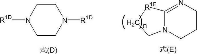
R1Dのアルキル基の炭素数は特に制限されないが、1~6が好ましく、1又は2がより好ましい。式(D)で表される化合物としては、例えば、N,N’-ジメチルピペラジン、及び、1,4-ジアザビシクロ[2.2.2]オクタン(DABCO)等が挙げられ、DABCOが好ましい。
また、処理液がより優れた残渣除去能を有する点で、防食剤としては、構造中に水酸基を含む式(A)で表される化合物、式(C)で表される化合物、及び、糖アルコールからなる群から選択される少なくとも1種を含有することが更に好ましい。上記の傾向は含フッ素化合物がフッ化アンモニウムである場合により顕著である。

上記式(B)において、R1B~R4Bは、それぞれ独立に、水素原子、又は、置換若しくは無置換の炭化水素基を表す。
上記式(C)において、R1C、R2C及びRNは、それぞれ独立に、水素原子、又は、置換若しくは無置換の炭化水素基を表す。また、R1CとR2Cとが結合して環を形成してもよい。
また、炭化水素基が置換されている場合の置換基としては、例えば、水酸基、カルボキシ基、及び、置換若しくは無置換のアミノ基(アミノ基が置換されている場合の置換基としては、炭素数1~6のアルキル基が好ましく、炭素数1~3のアルキル基がより好ましい)が挙げられる。
なお、式(A)においては、構造中に水酸基、カルボキシ基及び置換若しくは無置換のアミノ基(アミノ基が置換されている場合の置換基としては、炭素数1~6のアルキル基が好ましく、炭素数1~3のアルキル基がより好ましい)から選ばれる基を少なくとも1つ含む。
式(A)で表される化合物としては、例えば、1-チオグリセロール、L-システイン、メルカプトプロピオン酸、及び、チオリンゴ酸(メルカプトコハク酸)等が挙げられる。
R1B~R4Bで表される置換若しくは無置換の炭化水素基としては、例えば、メチル基、エチル基、プロピル基及びt-ブチル基等の炭素数1~6の炭化水素基が好ましく挙げられる。
式(B)で表される化合物としては、例えば、カテコール、t-ブチルカテコール等が挙げられる。
R1C、R2C及びRNで表される置換若しくは無置換の炭化水素基としては、例えば、メチル基、エチル基、プロピル基、ブチル基等の炭素数1~6の炭化水素基が好ましい。
また、R1CとR2Cとが結合して環を形成することが好ましく、R1CとR2Cとが結合して形成する環としては、ベンゼン環が好ましい。R1CとR2Cとが結合して環を形成した場合、更に置換基(例えば、炭素数1~5の炭化水素基)を有していてもよく、置換基としては、メチル基が好ましい。
式(C)で表される化合物としては、例えば、1H-1,2,3-トリアゾール、ベンゾトリアゾール、5-メチル-1H-ベンゾトリアゾール等が挙げられる。
防食剤は1種を単独で用いても、2種以上を併用してもよい。2種以上の防食剤を併用する場合には、合計含有量が上記範囲内であることが好ましい。
上記実施態様に係る処理液中の防食剤に対するカルシウムの含有質量比(カルシウムの含有量(B)/防食剤の含有量(C)、以下「B/C」ともいう。)は特に制限されないが、1.0×10-10以上が好ましく、6.0×10-10以上がより好ましく、1.0×10-4以下が好ましく、0.9×10-5以下がより好ましく、1.0×10-6以下がより好ましく、1.0×10-7以下が更に好ましく、2.0×10-8以下が特に好ましい。
B/Cが1.0×10-4以下だと、処理液はCoに対するより優れた防食性を有する。
B/Cが5.0×10-10以上だと、処理液はより優れた防食性を有する。
一方で、B/Cが0.9×10-5以下だと、処理液はより優れた残渣除去能を有する。
また、B/Cが1.0×10-6以下だと、処理液はより優れた残渣除去能を有し、かつ欠陥の発生がより抑制される。
また、B/Cが2.0×10-8以下だと、処理液はより優れた残渣除去能を有し、かつ欠陥の発生が更に抑制される。
本発明の他の実施態様に係る処理液は、以下で説明する任意成分を更に含有してもよい。
有機溶剤としては特に制限されず、公知の有機溶剤を用いることができ、親水性有機溶剤が好ましい。なお、本明細書において親水性有機溶剤とは、25℃の条件下において、100gの水に対して0.1g以上溶解させることができる有機溶剤のことを意図し、親水性有機溶剤としては、水といずれの比率においても均一に混合可能な有機溶剤が好ましい。
例えば、上記処理液を使用する前後に行う有機溶剤洗浄において用いる有機溶剤が上記の有機溶剤であると、本発明の効果がより顕著に得られる。
有機溶剤は、1種を単独で用いても、2種以上を併用してもよい。2種以上の有機溶剤を併用する場合には、合計含有量が上記範囲内であることが好ましい。
上記処理液は、水を含有することが好ましい。
例えば、本発明の処理液を使用する前後に行う水洗浄において用いる水が上記の水であると、本発明の効果がより顕著に得られる。
処理液が水を含有する場合、処理液中の有機溶剤の含有量、及び上記水の含有量を調整することで、その液性を水系、又は溶剤系のいずれの処方にもすることができる。本明細書において、処理液中の水の含有量が有機溶剤の含有量よりも多い処理液を「水系処理液」といい、処理液中の有機溶剤の含有量が水の含有量よりも多い処理液を「溶剤系処理液」ともいう。
水系処理液とする場合、水の含有量が、処理液全質量に対して20~98質量%であり、有機溶剤の含有量が、処理液全質量に対して1~40質量%であることが好ましい。
水系処理液とする場合の水の含有量は、処理液全質量に対して、35~98質量%が好ましく、50~95質量%がより好ましい。
水系処理液とする場合の有機溶剤の含有量は、処理液全質量に対して、5~35質量%が好ましく、10~30質量%がより好ましい。
溶剤系処理液とする場合、水の含有量が、処理液全質量に対して1~40質量%であり、有機溶剤の含有量が、処理液全質量に対して20~98質量%であることが好ましい。
溶剤系処理液とする場合の水の含有量は、処理液全質量に対して、1~30質量%が好ましく、2~25質量%がより好ましく、4~20質量%が更に好ましい。
溶剤系処理液とする場合の有機溶剤の含有量は、処理液全質量に対して、40~98質量%が好ましく、45~98質量%がより好ましく、50~95質量%が更に好ましい。
処理液全質量に対して、水の含有量が1~40質量%であり、有機溶剤の含有量が40~98質量%であると、処理液はCoに対するより優れた防食性を有する。また、この場合、有機溶剤の含有量が58質量%超であると、処理液は、より優れたタングステンに対する防食性を有し、有機溶剤の含有量が68質量%超であると、処理液は、より優れたSiO2に対する防食性を有する。一方で、有機溶剤の含有量が58質量%以下であると、処理液はより優れた残渣除去能を有する。
上記の傾向は、含フッ素化合物が「NH4F」の場合により顕著である。
上記処理液は、鉛を含有してもよい。
鉛は、イオン、錯化合物、塩化合物及び合金など、いずれの形態であってもよい。また、鉛は、粒子(パーティクル)状態であってもよい。
鉛は、処理液に含まれる各成分(原料)に不可避的に含有されていてもよいし、処理液の製造時に、処理液に不可避的に混入されてもよいし、処理液及び/又は原料に意図的に添加されたてもよい。
鉛の含有量が、10質量ppb以下だと、処理液はより優れた残渣除去能を有する。
また、鉛の含有量が0.1質量ppt以上9質量ppb未満だと、欠陥の発生がより抑制される。
上記実施態様に係る処理液中の防食剤に対する鉛の含有質量比(鉛の含有量(D)/防食剤の含有量(C)、以下「D/C」ともいう。)は特に制限されないが、6.0×10-11以上が好ましく、1.0×10-10以上がより好ましく、1.0×10-4以下が好ましく、1.0×10-6未満がより好ましく、1.0×10-8以下が更に好ましく、2.0×10-9以下が特に好ましい。
D/Cが0.6×10-11以上だと、処理液はより優れた残渣除去能を有し、かつ欠陥の発生がより抑制される。
一方で、D/Cが1.0×10-6未満だと、処理液はより優れた残渣除去能を有する。
また、D/Cが1.0×10-8以下だと、欠陥の発生がより抑制される。
処理液は無機酸を含有してもよい。無機酸は上述した含フッ素化防物及び防食剤とは異なる化合物であり、無機酸からは、含フッ素化合物は除く。
無機酸としては特に制限されず、公知の無機酸を用いることができる。
無機酸としては例えば、硝酸、硫酸、及び塩酸等が挙げられ、なかでも、硝酸が好ましい。
処理液中の無機酸の含有量としては特に制限されないが、処理液全質量に対して0.01質量%以上が好ましく、0.1質量%以上がより好ましく、20質量%以下が好ましく、10質量%以下がより好ましく、3質量%以下が更に好ましい。
無機酸の含有量が上記範囲内だと、処理液はより優れた本発明の効果を有する。
無機酸は、1種を単独で用いても、2種以上を併用してもよい。2種以上の無機酸を併用する場合には、合計含有量が上記範囲内であることが好ましい。
上記実施態様に係る処理液中の無機酸に対する鉛の含有質量比(鉛の含有量(D)/無機酸の含有量(E)、以下「D/E」ともいう。)は特に制限されないが、1.0×10-10以上が好ましく、1.0×10-4以下が好ましく、1.0×10-4未満が好ましく、1.0×10-8以下がより好ましい。
D/Eが1.0×10-4以下だと、処理液はより優れた残渣除去能を有する。
D/Eが1.0×10-4未満だと、鉛と無機酸によって生ずる難溶性及び/又は不溶性の塩化合物の過度な発生が抑制されると推測され、結果的に、欠陥の発生がより抑制される。
また、D/Eが1.0×-10以上だと、欠陥の発生がより抑制される。
上記実施態様に係る処理液中の防食剤に対する無機酸の含有質量比(無機酸の含有量(E)/防食剤の含有量(C)、以下「E/C」ともいう。)は特に制限されないが、0.01以上が好ましく、0.1以上がより好ましく、10以下が好ましく、1以下がより好ましい。
E/Cが上記範囲内だと、処理液はより優れた本発明の効果を有する。
また、E/Cが10以下だと、処理液はより優れたCoに対する防食性を有する。
また、E/Cが0.1~1だと、欠陥の発生がより抑制される。
上記処理液は、酸化剤を含有することが好ましい。酸化剤は、上記含フッ素化合物、防食剤、及び無機酸とは異なる化合物である。
酸化剤としては特に制限されず公知の酸化剤を用いることができる。
酸化剤としては例えば、過酸化水素、過酸化物、ヨウ素酸塩、過ヨウ素酸塩、次亜塩素酸塩、亜塩素酸塩、塩素酸塩、過塩素酸塩、過硫酸塩、重クロム酸塩、過マンガン酸塩、オゾン水、銀(II)塩、及び鉄(III)塩等が挙げられ、なかでも、過酸化水素がこのましい。
酸化剤の含有量が上記範囲内だと、処理液はより優れた本発明の効果を有する。
なお、酸化剤は1種を単独で用いても、2種以上を併用してもよい。2種以上の酸化剤を併用する場合には、合計含有量が上記範囲内であることが好ましい。
上記実施態様に係る処理液中の酸化剤に対す無機酸の含有質量比(無機酸の含有量(D)/酸化剤の含有量(F)、以下「E/F」ともいう。)は特に制限されないが、0.01~10が好ましい。
E/Fが上記範囲内だと処理液はより優れた本発明の効果を有する。
処理液は、上記以外の他の添加剤を含有してもよい。他の添加剤としては、例えば、pH調整剤、シリコン系界面活性剤、及びフッ素系界面活性剤等が挙げられる。
次に、上記実施態様に係る処理液の用途について説明する。
上記処理液は、半導体デバイス用の処理液である。本明細書において、「半導体デバイス用」とは、半導体デバイスの製造の際に用いられるという意味である。上記処理液は、半導体デバイスを製造するためのいずれの工程にも用いることができ、例えば、基板上に存在する絶縁膜、レジスト、反射防止膜、エッチング残渣物、及びアッシング残渣物などの処理に用いることができる。なお、本明細書においては、エッチング残渣物、及びアッシング残渣物を併せて残渣物という。
処理液は、感活性光線性又は感放射線性組成物を用いてレジスト膜を形成する工程の前に、組成物の塗布性を改良するために基板上に塗布されるプリウェット液、レジスト膜及びレジスト膜の残渣物の少なくとも一方であるレジストの除去に使用されるレジスト除去液(剥離液)、金属層(例えば、Co、又はW(タングステン)等を含有する。)又は層間絶縁膜(例えばSiOX、SiN、又はSiOC等を含有する。)上に付着した残渣物の除去などに用いられる洗浄液(例えば、リンス液など)、パターン形成用の各種レジスト膜の除去に用いられる溶液(例えば、除去液及び剥離液など)、及び、永久膜(例えば、カラーフィルタ、透明絶縁膜、及び樹脂製のレンズ)等を半導体基板から除去するために用いられる溶液(例えば、除去液及び剥離液など)、などとして用いられる。また、パターン形成用の各種レジストの現像液としても使用できる。なお、永久膜の除去後の半導体基板は、再び半導体デバイスの使用に用いられることがあるため、永久膜の除去は、半導体デバイスの製造工程に含むものとする。
上記処理液は、上記用途のうち、1つの用途のみに用いられてもよいし、2以上の用途に用いられてもよい。
上記処理液は、本発明の効果を有するとともに、金属配線及びプラグ(本明細書においては、これらをあわせて「金属層」という。)、並びに層間絶縁膜に対する優れた防食性を有するため、上記基板の処理に用いることができる。
上記処理液は、その原料を複数に分割したキットとしてもよい。特に限定はされないが、処理液をキットとする具体的な方法としては、例えば、第1液として含フッ素化合物を準備し、第2液として含フッ素化合物を除くその他の成分を含有する液組成物を準備する態様が挙げられる。
また、処理液は、濃縮液として準備してもよい。この場合、使用時に水及び/又は有機溶剤で希釈して使用することができる。
液収容体は、上記処理液を含有する。液収容体としては、容器と、液と、を含有する液収容体であって、上記液は、含フッ素化合物と、防食剤と、カルシウムと、を含有する半導体デバイス用の処理液であって、処理液中の含フッ素化合物の含有量に対する、カルシウムの含有量が、1.0×10⁻¹⁰~1.0×10⁻⁴である処理液である、液収容体が挙げられる。
また、上記液としては、処理液に代えて、上記濃縮液及び/又はキットとすることができる。
上記容器としては、半導体用途向けに、容器内のクリーン度が高く、不純物の溶出が少ないものが好ましい。
上記容器の具体例としては、例えば、アイセロ化学(株)製の「クリーンボトル」シリーズ、及び、コダマ樹脂工業製の「ピュアボトル」などが挙げられる。また、原材料及び薬液への不純物混入(コンタミ)防止を目的として、容器内壁を6種の樹脂からなる6層構造である多層容器、6種の樹脂からなる7層構造である多層容器を使用することも好ましい。これらの容器としては例えば特開2015-123351号公報に記載の容器が挙げられるが、これらに限定されない。
上記容器の内壁は、ポリエチレン樹脂、ポリプロピレン樹脂、及びポリエチレン-ポリプロピレン樹脂からなる群より選択される1種以上の樹脂、これとは異なる樹脂、並びにステンレス、ハステロイ、インコネル、及びモネル等の金属で形成される、又は被覆されることが好ましい。
このような内壁を有する容器の具体例としては、例えば、Entegris社製 FluoroPurePFA複合ドラム等が挙げられる。また、特表平3-502677号公報の第4頁等、国際公開第2004/016526号パンフレットの第3頁等、及び、国際公開第99/46309号パンフレットの第9頁及び16頁等に記載の容器も用いることができる。
上記電解研磨された金属材料の製造に用いられる金属材料は、クロム及びニッケルからなる群から選択される少なくとも1種を含有し、クロム及びニッケルの含有量の合計が金属材料全質量に対して25質量%超である金属材料であることが好ましく、例えばステンレス鋼、及びニッケル-クロム合金等が挙げられる。
金属材料におけるクロム及びニッケルの含有量の合計は、金属材料全質量に対して25質量%以上が好ましく、30質量%以上がより好ましい。
なお、金属材料におけるクロム及びニッケルの含有量の合計の上限値としては特に制限されないが、一般的に90質量%以下が好ましい。
ニッケル-クロム合金としては、例えば、ハステロイ(商品名、以下同じ。)、モネル(商品名、以下同じ)、及びインコネル(商品名、以下同じ)等が挙げられる。より具体的には、ハステロイC-276(Niの含有量:63質量%、Crの含有量:16質量%)、ハステロイ-C(Niの含有量:60質量%、Crの含有量:17質量%)、ハステロイC-22(Niの含有量:61質量%、Crの含有量:22質量%)等が挙げられる。
また、ニッケル-クロム合金は、必要に応じて、上記した合金の他に、更に、ホウ素、ケイ素、タングステン、モリブデン、銅、及びコバルト等を含有していてもよい。
なお、金属材料はバフ研磨されていることが好ましい。バフ研磨の方法は特に制限されず、公知の方法を用いることができる。バフ研磨の仕上げに用いられる研磨砥粒のサイズは特に制限されないが、金属材料の表面の凹凸がより小さくなりやすい点で、#400以下が好ましい。
なお、バフ研磨は、電解研磨の前に行われることが好ましい。
また、金属材料は、研磨砥粒のサイズなどの番手を変えて行われる複数段階のバフ研磨、酸洗浄、及び磁性流体研磨などを、1又は2以上組み合わせて処理されてもよい。
上記処理液の製造方法としては特に制限されず、公知の製造方法を用いることができる。上記処理液の製造方法としては、例えば、上記各成分を混合する方法が挙げられる。
なお、各成分を混合する順序は特に制限されない。濃縮液及びキットについても上記と同様の方法により製造されることが好ましい。
また液収容体は、上記の方法により製造した処理液、濃縮液、及びキットを容器に充填することによって製造することができる。
上記製造方法は、液中に含まれるカルシウムの含有量を所望の範囲内に調整することが好ましい。更に異物及び粗大粒子等を液中から除去するために、液をろ過する、ろ過工程を含有することが好ましい。
ろ過の方法としては特に制限されず、公知のろ過方法を用いることができる。なかでも、フィルタを用いたフィルタリングが好ましい。
これらの素材により形成されたフィルタを使用することで、欠陥の原因となり易い極性の高い異物を、処理液からより効果的に除去でき、又処理液中のカルシウムの含有量をより効率的に調整することができる。
なお、臨界表面張力の値は、製造メーカーの公称値である。臨界表面張力が上記範囲のフィルタを使用することで、欠陥の原因となり易い極性の高い異物を、処理液からより効果的に除去でき、又処理液中のカルシウムの含有量をより効率的に調整することができる。
更に、処理液中のカルシウムの含有量をより効率的に調整することができる点で、フィルタの孔径は0.05μm以下が好ましい。カルシウムの含有量を調整する場合のフィルタの孔径としては、0.005μm以上0.04μm以下がより好ましく、0.01μm以上0.02μm以下が更に好ましい。上記の範囲内であると、ろ過に必要な圧力が低く維持ができ、効率良く濾過することができる。
1回目のフィルタリングの孔径より2回目以降の孔径が同じ、又は、小さい方が好ましい。また、上述した範囲内で異なる孔径の第1のフィルタを組み合わせてもよい。ここでの孔径は、フィルタメーカーの公称値を参照できる。市販のフィルタとしては、例えば、日本ポール株式会社、アドバンテック東洋株式会社、日本インテグリス株式会社(旧日本マイクロリス株式会社)又は株式会社キッツマイクロフィルタ等が提供する各種フィルタの中から選択できる。また、ポリアミド製の「P-ナイロンフィルター(孔径0.02μm、臨界表面張力77mN/m)」;(日本ポール株式会社製)、高密度ポリエチレン製の「PE・クリーンフィルタ(孔径0.02μm)」;(日本ポール株式会社製)、及び高密度ポリエチレン製の「PE・クリーンフィルタ(孔径0.01μm)」;(日本ポール株式会社製)も使用することができる。
フィルタリングでは、粒子性の異物及び/又は不純物が除去できるが、上記温度で行われると、処理液中に溶解している粒子性の異物及び/又は不純物の量が少なくなるため、フィルタリングがより効率的に行われる。
上記製造方法は、更に、処理液、濃縮液、キット及び容器からなる群から選択される少なくとも1種を除電する、除電工程を含有してもよい。なお、除電の具体的方法については後述する。
本発明の一実施態様に係る基板の洗浄方法は、上記処理液を用いて、所定の基板を洗浄する洗浄工程Bを有する。また、上記基板の洗浄方法は、洗浄工程Bの前に、上記処理液を調製する処理液調製工程Aを有していてもよい。
以下の基板の洗浄方法の説明においては、洗浄工程Bの前に処理液調製工程Aを実施する場合を一例として示すが、これに限定されず、本発明の基板の洗浄方法は、予め準備された上記処理液を用いて行われてもよい。
上記基板の洗浄方法の洗浄対象物は、一実施態様において、Coを含有する金属層を備えることが好ましい。
また、上記基板の洗浄方法の洗浄対象物は、一実施態様において、Wを含有する金属層を備えることが好ましい。
また、上記基板の洗浄方法の洗浄対象物は、一実施態様において、SiOx、SiN、及びSiOCからなる群から選択される少なくとも1種を含有する層を備えることが好ましい。なお、xは1~3の数である。
上記洗浄対象物としては、例えば、基板上に、金属層、層間絶縁膜、メタルハードマスクを少なくともこの順に備えた積層体が挙げられる。積層体は、更に、ドライエッチング工程等を経たことにより、金属層の表面を露出するようにメタルハードマスクの表面(開口部)から基板に向かって形成されたホールを有してもよい。
上記のような、ホールを有する積層体の製造方法は特に制限されないが、通常、基板と、金属層と、層間絶縁膜と、メタルハードマスクとをこの順で有する処理前積層体に対して、メタルハードマスクをマスクとして用いてドライエッチング工程を実施して、金属層の表面が露出するように層間絶縁膜をエッチングすることにより、メタルハードマスク及び層間絶縁膜内を貫通するホールを設ける方法が挙げられる。
なお、メタルハードマスクの製造方法は特に制限されず、例えば、まず、層間絶縁膜上に所定の成分を含む金属層を形成して、その上に所定のパターンのレジスト膜を形成する。次に、レジスト膜をマスクとして用いて、金属層をエッチングすることで、メタルハードマスク(すなわち、金属層がパターニングされた膜)を製造する方法が挙げられる。
また、積層体は、上述の層以外の層を有していてもよく、例えば、エッチング停止膜、反射防止層等が挙げられる。
図1に示す積層体10は、基板1上に、金属層2、エッチング停止層3、層間絶縁膜4、メタルハードマスク5をこの順に備え、ドライエッチング工程等を経たことで所定位置に金属層2が露出するホール6が形成されている。つまり、図1に示す洗浄対象物は、基板1と、金属層2と、エッチング停止層3と、層間絶縁膜4と、メタルハードマスク5とをこの順で備え、メタルハードマスク5の開口部の位置において、その表面から金属層2の表面まで貫通するホール6を備える積層体である。ホール6の内壁11は、エッチング停止層3、層間絶縁膜4及びメタルハードマスク5からなる断面壁11aと、露出された金属層2からなる底壁11bとで構成され、ドライエッチング残渣物12が付着している。
また、上記基板の洗浄方法は、ドライエッチング工程の後にドライアッシング工程が行われた積層体に対して実施してもよい。
以下、上述した積層体の各層構成材料について説明する。
メタルハードマスクは、Cu、Co、W、AlOx、AlN、AlOxNy、WOx、Ti、TiN、ZrOx、HfOx及びTaOxからなる群より選択される成分を少なくとも1種含有することが好ましい。ここで、x、yは、それぞれ、x=1~3、y=1~2で表される数が好ましい。
上記メタルハードマスクの材料としては、例えば、TiN、WO2、及びZrO2等が挙げられる。
層間絶縁膜の材料は、特に限定されず、例えば、好ましくは誘電率kが3.0以下、より好ましくは2.6以下のものが挙げられる。
具体的な層間絶縁膜の材料としては、SiOX、SiN、SiOC、及び、ポリイミド等の有機系ポリマー;等が挙げられる。なお、xは1~3で表される数が好ましい。
エッチング停止層の材料は、特に限定されない。具体的なエッチング停止層の材料としてはSiN、SiON、SiOCN系材料、AlOxなどの金属酸化物が挙げられる。なお、xは0より大きく、3未満の数が好ましい。
金属層を形成する材料は、コバルト及び/又はタングステンを含有することが好ましい。また、コバルト及び/又はタングステンは、他の金属との合金であってもよい。
本発明の配線材料は、コバルト以外の金属、窒化金属又は合金を更に含有していてもよい。具体的には、銅、チタン、チタン-タングステン、窒化チタン、タングステン、タンタル、タンタル化合物、クロム、クロム酸化物、及び、アルミニウム等が挙げられる。
ここでいう「基板」には、例えば、単層からなる半導体基板、及び、多層からなる半導体基板が含まれる。
単層からなる半導体基板を構成する材料は特に限定されず、一般的に、シリコン、シリコンゲルマニウム、GaAsのような第III-V族化合物、又はそれらの任意の組み合わせから構成されることが好ましい。
多層からなる半導体基板である場合には、その構成は特に限定されず、例えば、上述のシリコン等の半導体基板上に金属線及び誘電材料のような相互接続構造(interconnect features)などの露出した集積回路構造を有していてもよい。相互接続構造に用いられる金属及び合金としては、アルミニウム、銅と合金化されたアルミニウム、銅、チタン、タンタル、コバルト、シリコン、窒化チタン、窒化タンタル、及びタングステンが挙げられるが、これらに限定されるものではない。また、半導体基板上に、層間誘電体層、酸化シリコン、窒化シリコン、炭化シリコン及び炭素ドープ酸化シリコン等の層を有していてもよい。
処理液調製工程Aは、上記処理液を調製する工程である。本工程で使用される各成分は、上述した通りである。
本工程の手順は特に制限されず、例えば、所定の成分を撹拌混合することにより処理液を調製する方法が挙げられる。なお、各成分は、一括して添加してもよいし、複数回に渡って分割して添加してもよい。
また、処理液に含まれる各成分は、半導体グレードに分類されるもの、又は、それに準ずる高純度グレードに分類されるものを使用することが好ましい。また、原材料の時点で不純物が多い成分に関しては、フィルタリングによる異物除去、イオン交換樹脂などによるイオン成分低減を行ったものを用いることが好ましい。
洗浄工程Bで洗浄される洗浄対象物としては、上述した積層体が挙げられ、上述した通り、ドライエッチング工程が施されてホールが形成された積層体10が例示される(図1参照)。なお、この積層体10には、ホール6内にドライエッチング残渣物12が付着している。
なお、ドライエッチング工程の後に、ドライアッシング工程が行われた積層体を、洗浄対象物としてもよい。
浸漬バッチ方式(処理槽内で複数枚の洗浄対象物を浸漬し処理するバッチ方式)で洗浄する場合には、洗浄時間は、例えば、60分以内であり、1~60分であることが好ましく、3~20分であることがより好ましく、4~15分であることが更に好ましい。
機械的撹拌方法としては、例えば、洗浄対象物上で処理液を循環させる方法、洗浄対象物上で処理液を流過又は噴霧させる方法、超音波又はメガソニックにて処理液を撹拌する方法等が挙げられる。
上記基板の洗浄方法は、洗浄工程Bの後に、洗浄対象物を溶剤ですすいで清浄するリンス工程B2を更に含有してもよい。
リンス工程B2は、洗浄工程Bに連続して行われ、リンス溶剤(リンス液)で5秒~5分にわたってすすぐ工程であることが好ましい。リンス工程B2は、上述の機械的撹拌方法を用いて行ってもよい。
リンス溶剤としては、水酸化アンモニウム水溶液、脱イオン水、メタノール、エタノール及びイソプロピルアルコールが好ましく、水酸化アンモニウム水溶液、脱イオン水及びイソプロピルアルコールであることがより好ましく、水酸化アンモニウム水溶液及び脱イオン水であることが更に好ましい。
リンス溶剤を洗浄対象物に接触させる方法としては、上述した処理液を洗浄対象物に接触させる方法を同様に適用することができる。
リンス工程B2におけるリンス溶剤の温度は、16~27℃であることが好ましい。
上述した処理液は、リンス工程B2のリンス溶剤として使用してもよい。
上記基板の洗浄方法は、リンス工程B2の後に洗浄対象物を乾燥させる乾燥工程B3を含有してもよい。
乾燥方法としては、特に限定されない。乾燥方法としては、例えば、スピン乾燥法、洗浄対象物上に乾性ガスを流過させる方法、ホットプレート若しくは赤外線ランプのような加熱手段によって基板を加熱する方法、マランゴニ乾燥法、ロタゴニ乾燥法、IPA(イソプロピルアルコール)乾燥法、又はそれらの任意の組み合わせが挙げられる。
乾燥時間は、用いる特定の方法に依存するが、一般的には、30秒~数分であることが好ましい。
本発明の一の実施態様に係る基板の洗浄方法は、上記処理液調製工程Aの前に、上記含フッ素化合物、及び上記防食剤からなる群から選択される少なくとも1種から、カルシウムイオンを除去するイオン除去工程F、及び/又は上記処理液調製工程Aの後であって上記洗浄工程Bの前に、上記処理液中のカルシウムイオンを除去するイオン除去工程Gを含有する、基板の洗浄方法である。例えば、イオン除去工程F、処理液調製工程A、イオン除去工程G、及び洗浄工程Bをこの順に有する基板の洗浄方法、イオン除去工程F、処理液調製工程A及び洗浄工程Bをこの順に有する基板の洗浄方法、処理液調製工程A、イオン除去工程G及び洗浄工程Bをこの順に有する基板の洗浄方法が例として挙げられる。
上記イオン除去工程F及びイオン除去工程Gの少なくとも一方を実施することで、洗浄工程Bで用いられる処理液中における、含フッ素化合物の含有量に対する、カルシウムの含有量が、上述した範囲に調整されることが好ましい。特に、イオン除去工程F及びイオン除去工程Gの両方を実施することで、含フッ素化合物の含有量に対する、カルシウムの含有量が上述した範囲内に調整しやすくなるという利点がある。
イオン除去工程F、及び、イオン除去工程Gの具体的な方法としては、特に限定されないが、例えば蒸留及び/又はイオン交換膜による精製が挙げられる。
上記基板の洗浄方法は、上記処理液調製工程Aの後であって上記洗浄工程Bの前に、処理液中の粗大粒子を除去する粗大粒子除去工程Hを有することが好ましい。
処理液中の粗大粒子を低減又は除去することで、洗浄工程Bを経た後の洗浄対象物上に残存する粗大粒子の量を低減することができる。この結果、洗浄対象物上の粗大粒子に起因したパターンダメージを抑制でき、デバイスの歩留まり低下及び信頼性低下への影響も抑制することができる。
粗大粒子を除去するための具体的な方法としては、例えば、処理液調製工程Aを経た処理液を所定の除粒子径の除粒子膜を用いて濾過精製する方法等が挙げられる。
なお、粗大粒子の定義については、上述のとおりである。
上記基板の洗浄方法は、上記処理液調製工程Aにおける上記処理液の調製の際に水を用いて、上記処理液調製工程Aの前に上記水に対して除電を行う除電工程I、及び、上記処理液調製工程Aの後であって上記洗浄工程Bの前に、上記処理液に対して除電を行う除電工程Jからなる群から選択される少なくとも1種の工程を含有することが好ましい。例えば、除電工程I、処理液調製工程A、除電工程J及び洗浄工程Bをこの順に有する基板の洗浄方法、除電工程I、処理液調製工程A及び洗浄工程Bをこの順に有する基板の洗浄方法、処理液調製工程A、除電工程J及び洗浄工程Bをこの順に有する基板の洗浄方法が例として挙げられる。
洗浄対象物へ処理液を供給するための接液部の材質は、処理液中の含フッ素化合物の含有量に対するカルシウムの含有量を所定範囲内に維持するために、処理液に対して金属溶出のない材料で形成される、又は被覆されることが好ましい。上記の材料としては、例えば、液収容体に用いることができる容器の内壁に係る材料として既に説明した材料等が挙げられる。
なお、上記材料は樹脂であっても良い。上記材料が樹脂である場合、樹脂は電気伝導率が低く、絶縁性であることが多い。そのため、例えば、上記処理液を、内壁が樹脂で形成された配管、若しくは被覆された配管に通液した場合、又は、樹脂製の除粒子膜及び樹脂製のイオン交換樹脂膜により濾過精製を行った場合、処理液の帯電電位が増加して静電気災害を引き起こされるおそれがある。
このため、本発明の基板の洗浄方法では、上述の除電工程I及び除電工程Jの少なくとも一方の工程を実施し、処理液の帯電電位を低減させることが好ましい。また、除電を行うことで、基板への異物(粗大粒子など)の付着及び/又は洗浄対象物へのダメージ(腐食)をより抑制することができる。
除電方法としては、具体的には、水及び/又は処理液を導電性材料に接触させる方法が挙げられる。
水及び/又は処理液を導電性材料に接触させる接触時間は、0.001~1秒が好ましく、0.01~0.1秒がより好ましい。
樹脂の具体的な例としては、高密度ポリエチレン(HDPE)、高密度ポリプロピレン(PP)、6,6-ナイロン、テトラフルオロエチレン(PTFE)、テトラフルオロエチレンとパーフロロアルキルビニルエーテルの共重合体(PFA)、ポリクロロトリフルオロエチレン(PCTFE)、エチレン・クロロトリフルオロエチレン共重合体(ECTFE)、エチレン・四フッ化エチレン共重合体(ETFE)、及び、四フッ化エチレン・六フッ化プロピレン共重合体(FEP)などが挙げられる。
導電性材料としては、ステンレス鋼、金、白金、ダイヤモンド、及び、グラッシーカーボンなどが挙げられる。
排液回収工程CおよびEにおける排液回収手段は特に限定されない。回収した排液は、上記除電工程Jにおいて上述した容器に保存されることが好ましく、この時に除電工程Jと同様の除電工程を行ってもよい。また、回収した排液に濾過等を実施し不純物を除去する工程を設けてもよい。
本発明の一実施態様に係るレジストの除去方法は、レジスト膜及び上記レジスト膜の残渣物からなる群から選択される少なくとも1種であるレジストを、上述した処理液を用いて除去する工程(以下、「レジスト除去工程」ともいう。)を含有する。本明細書において、「レジストの除去」とは、レジストの設けられた基板などからレジストを「取り除く」という意味であり、「レジストを剥離して取り除くこと」及び「レジストを溶解して取り除くこと」なども含まれる。
上記実施態様に係るレジストの除去方法は、このように形成されたレジスト膜の除去に使用されてもよいし、レジスト膜をエッチング(プラズマエッチングなどのドライエッチング)及び/又はアッシング(プラズマアッシングなどのドライアッシング)などを行うことで生じた残渣物(副生成物も含む)の除去に使用されてもよい。
上記処理液を用いたレジストの除去においては、処理対象となるレジスト膜は特に限定されないが、例えば、ポジ型、ネガ型、及び、ポジ-ネガ兼用型のフォトレジストが挙げられる。
ポジ型レジストの具体例は、(メタ)アクリレート系樹脂、ケイ皮酸ビニール系樹脂、環化ポリイソブチレン系樹脂、アゾ-ノボラック系樹脂、ジアゾケトン-ノボラック系樹脂、並びに、ノボラック系樹脂及びポリヒドロキシスチレン系樹脂の少なくとも一方の樹脂、などが挙げられる。
ネガ型レジストの具体例は、アジド-環化ポリイソプレン系樹脂系、アジド-フェノール系樹脂、及び、クロロメチルポリスチレン系樹脂などが挙げられる。更に、ポジ-ネガ兼用型レジストの具体例は、ポリ(p-ブトキシカルボニルオキシスチレン)系樹脂などが挙げられる。
その他、パターニング用のレジストの例として、特許5222804号、特許5244740号、特許5244933号、特許5286236号、特許5210755号、特許5277128号、特許5303604号、特許5216892号、特許5531139号、特許5531078号、及び、特許5155803号の各公報に開示されたものを参照することができ、本明細書に引用して取り込む。
レジスト除去工程は、レジストに処理液を接触させることで実施される。この方法は特に限定されないが、例えば、タンクに入れた処理液中にレジストを有する積層体を浸漬する方法、レジスト上に処理液を噴霧する方法、レジスト上に処理液を流す方法、又はそれらの任意の組み合わせが挙げられる。レジスト除去性がより向上するという観点から、洗浄対象物を処理液中に浸漬する方法が好ましい。
レジストの除去時間(レジスト除去工程におけるレジストと処理液との接液時間)は、用いる除去方法及び処理液の温度などに応じて調整することができ、概ね、10秒~10分であり、30秒~5分が好ましい。
処理液のレジスト除去能力をより増進するために、機械的撹拌方法を用いてもよい。機械的撹拌方法としては、上述した基板洗浄方法の項で述べた通りであるので、その説明を省略する。
乾燥方法としては、特に限定されず、上述した基板洗浄方法における乾燥工程B3と同様の方法が挙げられるので、その説明を省略する。
実施例及び比較例の各処理液の調製にあたって、有機溶剤及び水については、特開2007―254168号公報に記載されている方法により精製を行い、処理液の調製に用いた。
表1に示す各成分を混合及び攪拌して混合液を得た後、混合液のフィルタリング処理及びろ過処理の少なくとも一方を実施して、実施例及び比較例の各処理液を得た。なお、各実施例及び比較例の処理液に含まれるカルシウムの含有量が表1に記載のとおりになるように、各処理の実施回数を適宜変えて行った。
なお、処理液中のカルシウム濃度は、フィルタリングによってCaを除去してコントロールした。より具体的には、Entegris社製 ポアサイズ15nm IEX PTFEを1段目に、続いて2段目にEntegris社製 ポアサイズ12nmPTFEを用いて循環ライン(循環ろ過ライン)を形成した。精製にあたってはこの循環ろ過ラインを使用し、循環を1~10回の間で実施した。循環回数の増加に伴ってCa濃度が低減できることを確認した。
また、各処理液のpHが所定の表1に記載した値になるよう、pH調整剤を用いて調整した。実施例及び比較例の各処理液の調製に用いた成分は以下の通りである。
・HF:フッ化水素酸
・TMAF:フッ化テトラメチルアンモニウム
・H2SiF6:ヘキサフルオロケイ酸
・HBF4:テトラフルオロホウ酸
・HPF6:ヘキサフルオロリン酸
・5-MBTA:5-メチル-1H-ベンゾトリアゾール
・ABA:アントラニル酸
・PAA:ポリアクリル酸(重量平均分子量:25000)
・BTA:ベンゾトリアゾール
・TAZ:1,2,4-トリアゾール
・DdA:ドデカン酸
・FS-3PG:ニューカルゲンFS-3PG(アニオン界面活性剤、竹本油脂社製)
・HLP-1:ホステンHLP-1(アニオン界面活性剤、日光ケミカルズ社製)
・CeCl3:塩化セリウム
・TGC:チオグリセロール
・TMA:メルカプトコハク酸(チオりんご酸)
・Cys:L-システイン
・SBTL:ソルビトール
・MPA:メルカプトプロピオン酸
・超純水
・EGME(エチレングリコールモノメチルエーテル)
・EGBE(エチレングリコールモノ-n-ブチルエーテル)
・DEGME(ジエチレングリコールモノメチルエーテル)
・MSA(メタンスルホン酸)
・HNO3:硝酸
・H2O2:過酸化水素
処理液中のカルシウムの含有量、及び鉛の含有量の測定は下記の方法により行った。
まず、各実施例、及び比較例の処理液1,000mLを合成石英製容器に入れ、マッフル炉を用いて、沸騰状態を維持できるよう加熱して灰化し、上記灰化した試料を超純水で溶解し、試料溶液を作製した。上記試料溶液を高周波誘導結合プラズマ発光分光分析(ICP-MS、島津製作所社製、ICPMS-2030)を用いて測定した。なお、測定結果は、表1にまとめた。
η1、η2は以下の方法により求めた。
実施例、及び比較例の各処理液を用いて、23℃における粘度η2(ローターの回転数1000rpm)と、粘度η1(ローターの回転数100rpm)とを測定した。得られた値から粘度の比率(粘度η1/η2)を算出した。粘度の測定には、粘度計「ブルックフィールド粘度計EV-3T」(製品名、EKO精機社製)を用いた。
pHメータ(製品名「卓上型pHメータ F-74BW」、HORIBA社製)を用いて、実施例及び比較例の各処理液の25℃におけるpHを測定した。
Coからなる膜(以下「Co膜」ともいう。)を準備して、そのエッチングレートに基づいて、防食性の評価を行った。Co膜の膜厚は、1000Å(1Åは、0.1nmを表す。)の膜厚である。
エッチングレートが低いほど、処理液はCo膜に対するより優れた腐食性を有する。
実施例及び比較例の各処理液を用いて、Co膜のエッチング処理をした。具体的には、実施例及び比較例の処理液中にCo膜を10分間浸漬して、処理液の浸漬前後におけるCo膜の膜厚差に基づいて、エッチングレート(Å/分)を算出した。
なお、処理前後のCo膜の膜厚は、エリプソメトリー(分光エリプソメーター、商品名「Vase」、ジェー・エー・ウーラム・ジャパン社製)を用いて、測定範囲250-1000nm、測定角度70度及び75度の条件で測定した。
また、Wからなる膜、及びSiO2からなる膜を準備して、上記と同様にしてエッチングレートを算出した。
なお、結果は膜の種類ごとに以下の基準により評価し、測定結果と評価を表1にまとめて示した。
<Co膜に対する防食性>
・A:Co膜のエッチングレートが20Å/分未満である。
・B:Co膜のエッチングレートが20Å/分以上、30Å/分未満である。
・C:Co膜のエッチングレートが30Å/分以上、40Å/分未満である。
・D:Co膜のエッチングレートが40Å/分以上、50Å/分未満である。
・E:Co膜のエッチングレートが50Å/分以上、60Å/分未満である。
・F:Co膜のエッチングレートが60Å/分以上である。
なお、Co膜に対する防食性としては、実用上「A」~「E」が好ましい。
<W膜に対する防食性>
・A:W膜のエッチングレートが10Å/分未満である。
・B:W膜のエッチングレートが10Å/分以上、20Å/分未満である。
・C:W膜のエッチングレートが20Å/分以上、30Å/分未満である。
・D:W膜のエッチングレートが30Å/分以上である。
<SiO2膜に対する防食性>
・A:SiO2膜のエッチングレートが10Å/分未満である。
・B:SiO2膜のエッチングレートが10Å/分以上、20Å/分未満である。
・C:SiO2膜のエッチングレートが20Å/分以上である。
残渣除去能はメタルハードマスクをプラズマエッチングした際に生成される残渣物の一種である酸化チタン(TiO2)からなるモデル膜を準備し、そのエッチングレートを評価した。つまり、エッチングレートが高い場合は、処理液はより優れた残渣除去能(「残渣物溶解性」ともいう。)を有するといえる。
・A:エッチングレートが5Å/分以上である。
・B:エッチングレートが3Å/分以上、5Å/分未満である。
・C:エッチングレートが1Å/分以上、3Å/分未満である。
・D:エッチングレートが0Å/分より大きく、1Å/分未満である。
・E:全く溶解しない。
ウェハ上表面検査装置(SP-5、KLA-Tencor社製)により、直径300mmのシリコン基板表面に存在する直径32nm以上の異物数及び各異物のアドレスを計測した。
そして、スピン回転ウェハ処理装置(イーケーシーテクノロジーズ社製)に、シリコン基板表面に存在する異物数を計測したウェハをセットした。
次に、セットされたウェハの表面に、実施例及び比較例の各処理液を1.5L/minの流量で1分間吐出した。その後、ウェハのスピン乾燥を行った。
得られた乾燥後のウェハについて、ウェハ上表面検査装置を用いて、ウェハ上の異物数及び異物の発生箇所を計測した。
そして、上記処理液をスピン乾燥した後に新たに増加した異物に対して、欠陥解析装置(SEM VISION G6、APPLIED MATERIALS社製)を用いてEDX(Energy dispersive X-ray spectrometry:エネルギー分散型X線分析)による元素解析を行った。カルシウム及び鉛を対象金属元素として、対象金属元素を含有する異物をパーティクルとしてカウントした。得られたパーティクルの数を以下の評価基準にしたがって評価した。結果を表1に示す。なお、実用上「A」~「C」が好ましい。
・A:対象金属元素を含有した直径32nm以上のパーティクルの数が0個以上100個未満である。
・B:対象金属元素を含有した直径32nm以上のパーティクルの数が100個以上500個未満である。
・C:対象金属元素を含有した直径32nm以上のパーティクルの数が500個以上1000個未満である。
・D:対象金属元素を含有した直径32nm以上のパーティクルの数が1000個以上である。
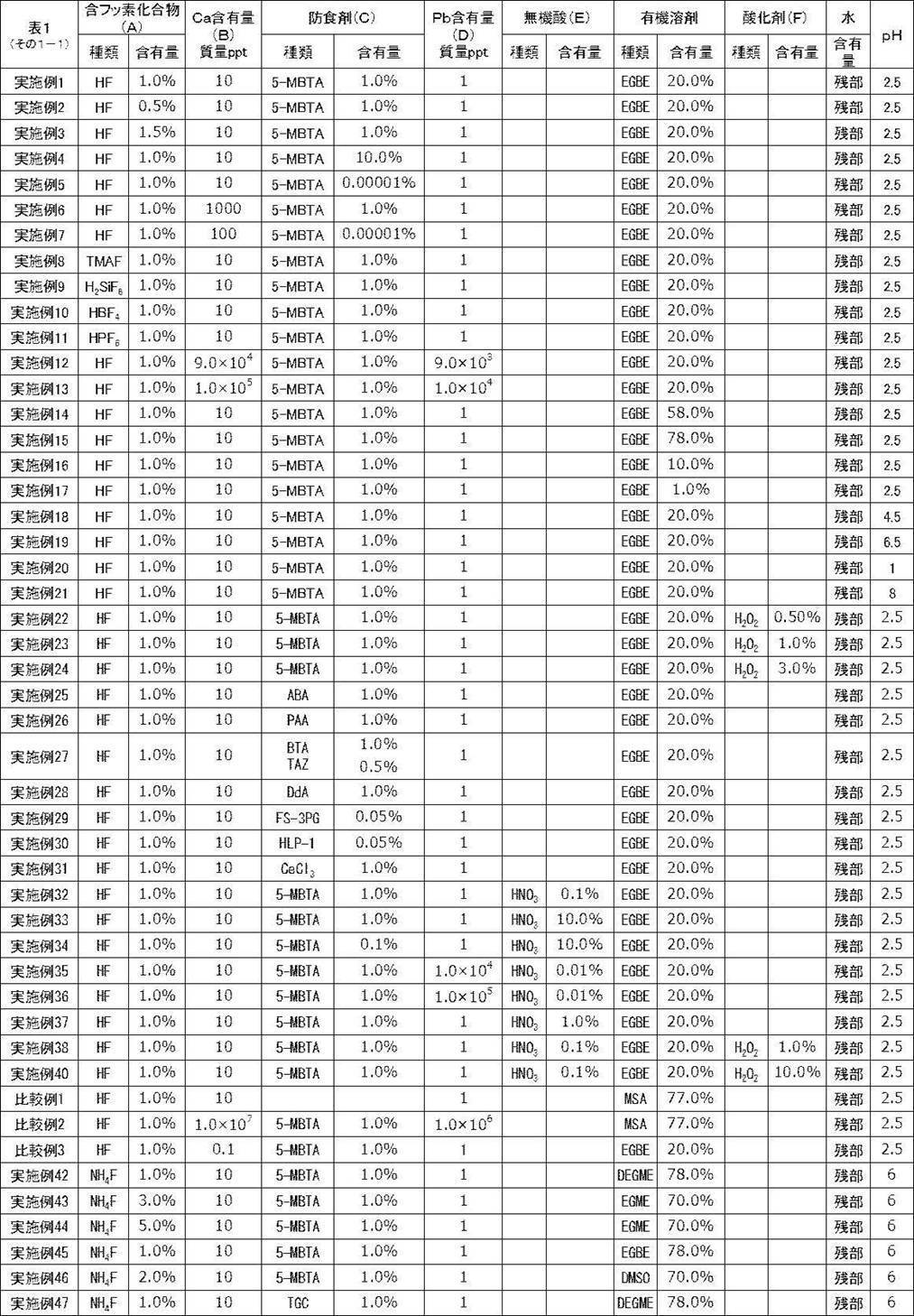
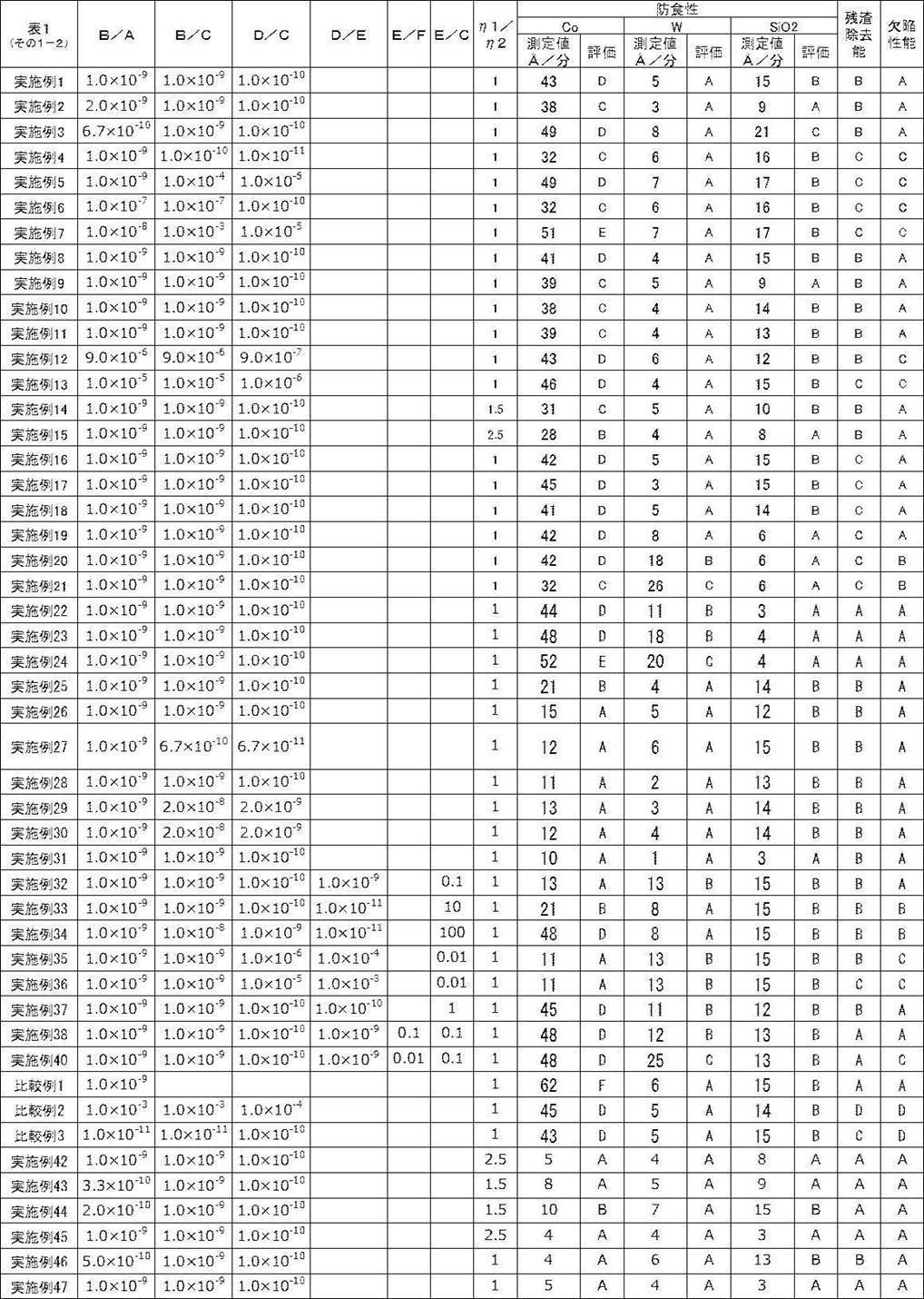
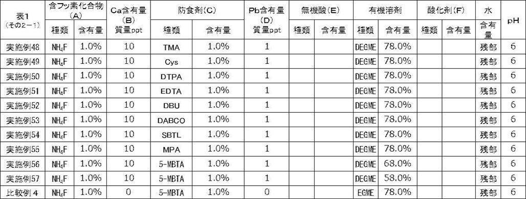

実施例1の処理液について、浸漬時間を20分とし、アース接地した材質SUS316で除電した他は同様にして、除電工程を経た場合と、経ない場合で各種評価を行なった。
実施例1の処理液について、評価試験1~3をそれぞれ5回連続して行った。その後、回収した液をタンクに入れなおし、その液で、再度上記試験を行った。
つまり、処理液を換えずに各5枚の被処理物を連続して処理し、6枚目の被処理物に対して上述の評価を行うことで各種性能を評価した。(上記を「リサイクル試験」とした。)
評価の結果、リサイクル試験をした場合は、リサイクル試験をしない場合と比較して、性能差はなく、問題ないことを確認した。
評価の結果、リサイクル試験をした場合は、リサイクル試験をしない場合と比較して、残渣除去性能及び欠陥性能に悪化が見られた。
一方、比較例1~3の処理液は所望の効果を有していなかった。
また、B/Cが1.0×10-4以下である実施例1、34、29、6、12、13及び5の処理液は、実施例7の処理液と比較して、Coに対するより優れた防食性を有していた。
また、E/Cが10以下である、実施例33の処理液は、実施例34の処理液と比較して、Coに対するより優れた防食性を有していた。
また、D/Eが1.0×10-10以上である、実施例37の処理液は、実施例33の処理液と比較して、より優れた欠陥性能を有していた。また、D/Eが1.0×10-4以下である、実施例35の処理液は、実施例36の処理液と比較して、より優れた残渣除去能を有していた。
また、D/Cが6.0×10-11以上である実施例28の処理液は、実施例4の処理液と比較してより優れた残渣除去能を有し、欠陥の発生がより抑制されていた。
また、鉛の含有量が10質量ppb以下の実施例35の処理液は、実施例36の処理液と比較して、より優れた残渣除去能を有していた。
また、pHが1.5超である、実施例1の処理液は、実施例20の処理液と比較してより優れた欠陥性能、及び残渣除去能を有していた。pHが7.0未満の実施例19の処理液は、実施例21の処理液と比較してより優れた欠陥性能を有していた。
また、含フッ素化合物がNH4Fである実施例45の処理液は、実施例15の処理液と比較して、Coに対するより優れた防食性を有していた。
また、防食剤の種類が、式(A)で表される化合物、式(C)で表される化合物、糖アルコール、ポリアミノカルボン酸又はその塩、式(D)で表される化合物、及び、式(E)で表される化合物からなる群から選択される少なくとも1種の化合物である、実施例42、実施例45、及び、実施例47~56の処理液は、実施例25の処理液と比較して、Coに対するより優れた防食性を有していた。
また、処理液全質量に対して、水の含有量が1~40質量%であり、有機溶剤の含有量が40~98質量%である実施例15の処理液は、実施例1の処理液と比較して、Coに対するより優れた防食性を有していた。
2 金属層
3 エッチング停止層
4 層間絶縁膜
5 メタルハードマスク
6 ホール
10 積層体
11 内壁
11a 断面壁
11b 底壁
12 ドライエッチング残渣物
Claims (30)
- 含フッ素化合物と、防食剤と、カルシウムと、を含有する半導体デバイス用の処理液であって、
前記処理液中の前記含フッ素化合物に対する、前記カルシウムの含有質量比が、1.0×10⁻¹⁰~1.0×10⁻⁴である、処理液。 - 前記防食剤に対する、前記カルシウムの含有質量比が、1.0×10⁻¹⁰~1.0×10⁻⁴である、請求項1に記載の処理液。
- 前記カルシウムの含有量が、前記処理液の全質量に対して、0.1質量ppt~1000質量ppbである、請求項1又は2に記載の処理液。
- 更に、有機溶剤を含有する、請求項1~3のいずれか一項に記載の処理液。
- 更に水を含有し、
前記水の含有量が、前記処理液の全質量に対して、20~98質量%であり、
前記有機溶剤の含有量が、前記処理液の全質量に対して、1~40質量%である、請求項4に記載の処理液。 - 更に水を含有し、
前記水の含有量が、前記処理液の全質量に対して、1~40質量%であり、
前記有機溶剤の含有量が、前記処理液の全質量に対して、20~98質量%である、請求項4に記載の処理液。 - 更に、無機酸を含有する、請求項1~6のいずれか一項に記載の処理液。
- 前記防食剤に対する、前記無機酸の含有質量比が0.01~10である、請求項7に記載の処理液。
- 更に、鉛を含有する、請求項1~8のいずれか一項に記載の処理液。
- 更に、鉛を含有し、前記無機酸に対する、前記鉛の含有質量比が、1.0×10⁻¹⁰~1.0×10⁻⁴である、請求項7又は8に記載の処理液。
- 前記防食剤に対する前記鉛の含有質量比が、6.0×10⁻¹¹~1.0×10⁻⁴である、請求項9又は10に記載の処理液。
- 前記鉛の含有量が、前記処理液の全質量に対して、0.1質量ppt~10質量ppbである、請求項9~11のいずれか一項に記載の処理液。
- 更に、酸化剤を含有する、請求項1~12のいずれか一項に記載の処理液。
- 更に、酸化剤を含有し、前記酸化剤に対する前記無機酸の含有質量比が0.01~10である、請求項7、8又は10に記載の処理液。
- 前記酸化剤が過酸化水素である請求項13又は14に記載の処理液。
- pHが1.5超7.0未満である、請求項1~15のいずれか一項に記載の処理液。
- 前記含フッ素化合物が、フッ化水素酸、フッ化アンモニウム、フッ化テトラメチルアンモニウム、テトラフルオロホウ酸、ヘキサフルオロリン酸、ヘキサフルオロケイ酸、テトラフルオロホウ酸アンモニウム、ヘキサフルオロリン酸アンモニウム、及びヘキサフルオロケイ酸アンモニウムからなる群から選択される少なくとも1種である、請求項1~16のいずれか一項に記載の処理液。
- 回転粘度計を用いて前記処理液の23℃における粘度を測定した場合に、回転数1000rpmにおける前記処理液の粘度に対する、回転数100rpmにおける前記処理液の粘度の比率が、1.0~20である、請求項1~17のいずれか一項に記載の処理液。
- 前記半導体デバイスが、Coを含有する金属層を備えた基板を含有し、
前記処理液が、前記金属層に対する処理に使用される、請求項1~18のいずれか一項に記載の処理液。 - 前記半導体デバイスが、Wを含有する金属層を備えた基板を含有し、
前記処理液が、前記金属層に対する処理に使用される、請求項1~19のいずれか一項に記載の処理液。 - 前記半導体デバイスが、SiOX、SiN、及びSiOCからなる群から選択される少なくとも1種を含有する層を備えた基板を含有し、
前記処理液が、前記層に対する処理に使用される、請求項1~20のいずれか一項に記載の処理液。なお、xは1~3の数を表す。 - 前記半導体デバイスの製造時にレジスト膜が形成され、
前記処理液が、前記レジスト膜、及び前記レジスト膜の残渣物からなる群から選択される少なくとも1種であるレジストの除去に使用される、請求項1~21のいずれか一項に記載の処理液。 - 請求項1~22のいずれか一項に記載の処理液を用いて、Coを含有する金属層を備えた基板を洗浄する、洗浄工程Bを含有する、基板の洗浄方法。
- 請求項1~22のいずれか一項に記載の処理液を用いて、Wを含有する金属層を備えた基板を洗浄する、洗浄工程Bを含有する、基板の洗浄方法。
- 請求項1~22のいずれか一項に記載の処理液を用いて、SiOX、SiN、及びSiOCからなる群から選択される少なくとも1種を含有する層を備えた基板を洗浄する、洗浄工程Bを含有する、基板の洗浄方法。なお、xは1~3の数を表す。
- 前記洗浄工程Bで使用された前記処理液の排液を回収する、排液回収工程Cと、
回収された前記処理液の排液を用いて、新たに準備されるCoを含有する金属層、Wを含有する金属層、並びにSiOX、SiN、及びSiOCからなる群から選択される少なくとも1種を含有する層、からなる群から選択される少なくとも1種を備えた基板を洗浄する、洗浄工程Dと、
前記洗浄工程Dで使用された前記処理液の排液を回収する、排液回収工程Eと、
前記洗浄工程Dと前記排液回収工程Eとを繰り返す工程とを含有する、請求項23~25のいずれか一項に記載の基板の洗浄方法。なお、xは0より大きく3未満の数を表す。 - 前記洗浄工程Bの前に、前記処理液を調製する処理液調製工程Aと、
前記処理液調製工程Aの前に、含フッ素化合物、及び防食剤からなる群から選択される少なくとも1種から、カルシウムイオンを除去する、イオン除去工程F、及び/又は、
前記処理液調製工程Aの後であって前記洗浄工程Bの前に、前記処理液中のカルシウムイオンを除去する、イオン除去工程Gを含有する、請求項23~26のいずれか一項に記載の基板の洗浄方法。 - 前記処理液調製工程Aにおける前記処理液の調製の際に水を用いて、
前記イオン除去工程Fが、含フッ素化合物、防食剤、及び水からなる群から選択される少なくとも1種から、カルシウムイオンを除去する工程である、請求項27に記載の基板の洗浄方法。 - 前記洗浄工程Bの前に、前記処理液を調製する処理液調製工程Aを有し、
前記処理液調製工程Aにおける前記処理液の調製の際に水を用いて、
前記処理液調製工程Aの前に、前記水に対して除電を行う除電工程I、及び前記処理液調製工程Aの後であって前記洗浄工程Bの前に、前記処理液に対して除電を行う除電工程Jからなる群から選択される少なくとも1種の工程を含有する、請求項23~28のいずれか一項に記載の基板の洗浄方法。 - レジスト膜及び前記レジスト膜の残渣物からなる群から選択される少なくとも1種であるレジストを、請求項1~22のいずれか一項に記載の処理液を用いて除去する工程を有する、レジストの除去方法。
Priority Applications (3)
| Application Number | Priority Date | Filing Date | Title |
|---|---|---|---|
| KR1020187033202A KR102111307B1 (ko) | 2016-06-02 | 2017-05-09 | 처리액, 기판의 세정 방법 및 레지스트의 제거 방법 |
| JP2018520750A JP6713044B2 (ja) | 2016-06-02 | 2017-05-09 | 処理液、基板の洗浄方法及びレジストの除去方法 |
| US16/180,107 US11225633B2 (en) | 2016-06-02 | 2018-11-05 | Treatment liquid, method for washing substrate, and method for removing resist |
Applications Claiming Priority (4)
| Application Number | Priority Date | Filing Date | Title |
|---|---|---|---|
| JP2016-111077 | 2016-06-02 | ||
| JP2016111077 | 2016-06-02 | ||
| JP2017016654 | 2017-02-01 | ||
| JP2017-016654 | 2017-02-01 |
Related Child Applications (1)
| Application Number | Title | Priority Date | Filing Date |
|---|---|---|---|
| US16/180,107 Continuation US11225633B2 (en) | 2016-06-02 | 2018-11-05 | Treatment liquid, method for washing substrate, and method for removing resist |
Publications (1)
| Publication Number | Publication Date |
|---|---|
| WO2017208749A1 true WO2017208749A1 (ja) | 2017-12-07 |
Family
ID=60478298
Family Applications (1)
| Application Number | Title | Priority Date | Filing Date |
|---|---|---|---|
| PCT/JP2017/017589 Ceased WO2017208749A1 (ja) | 2016-06-02 | 2017-05-09 | 処理液、基板の洗浄方法及びレジストの除去方法 |
Country Status (5)
| Country | Link |
|---|---|
| US (1) | US11225633B2 (ja) |
| JP (1) | JP6713044B2 (ja) |
| KR (1) | KR102111307B1 (ja) |
| TW (1) | TWI708840B (ja) |
| WO (1) | WO2017208749A1 (ja) |
Cited By (11)
| Publication number | Priority date | Publication date | Assignee | Title |
|---|---|---|---|---|
| WO2018181901A1 (ja) * | 2017-03-31 | 2018-10-04 | 関東化學株式会社 | 洗浄液組成物 |
| WO2019208685A1 (ja) * | 2018-04-27 | 2019-10-31 | 三菱瓦斯化学株式会社 | 水性組成物及びこれを用いた洗浄方法 |
| WO2019208684A1 (ja) * | 2018-04-27 | 2019-10-31 | 三菱瓦斯化学株式会社 | 水性組成物及びこれを用いた洗浄方法 |
| WO2020189683A1 (ja) * | 2019-03-19 | 2020-09-24 | Jsr株式会社 | 組成物及び基板の処理方法 |
| WO2021039701A1 (ja) * | 2019-08-29 | 2021-03-04 | 富士フイルム株式会社 | 処理液 |
| JPWO2021049330A1 (ja) * | 2019-09-11 | 2021-03-18 | ||
| JPWO2019208686A1 (ja) * | 2018-04-27 | 2021-05-27 | 三菱瓦斯化学株式会社 | 水性組成物及びこれを用いた洗浄方法 |
| JP2023124155A (ja) * | 2022-02-25 | 2023-09-06 | 富士フイルム株式会社 | 金属充填微細構造体 |
| JP2023126320A (ja) * | 2018-01-16 | 2023-09-07 | 株式会社トクヤマ | 次亜塩素酸イオンを含む半導体ウェハの処理液 |
| JP2023178293A (ja) * | 2018-01-30 | 2023-12-14 | ピーアールシー-デソト インターナショナル,インコーポレイティド | 金属基板を処理するためのシステムおよび方法 |
| WO2025204631A1 (ja) * | 2024-03-27 | 2025-10-02 | 富士フイルム株式会社 | 薬液、半導体デバイスの製造方法 |
Families Citing this family (14)
| Publication number | Priority date | Publication date | Assignee | Title |
|---|---|---|---|---|
| JP6713044B2 (ja) * | 2016-06-02 | 2020-06-24 | 富士フイルム株式会社 | 処理液、基板の洗浄方法及びレジストの除去方法 |
| JP6808730B2 (ja) * | 2016-06-03 | 2021-01-06 | 富士フイルム株式会社 | 処理液、基板洗浄方法およびレジストの除去方法 |
| US10920179B2 (en) * | 2016-11-10 | 2021-02-16 | Tokyo Ohka Kogyo Co., Ltd. | Cleaning solution and method for cleaning substrate |
| US11193094B2 (en) * | 2017-07-31 | 2021-12-07 | Mitsubishi Gas Chemical Company, Inc. | Liquid composition for reducing damage of cobalt, alumina, interlayer insulating film and silicon nitride, and washing method using same |
| JP7204760B2 (ja) * | 2018-02-14 | 2023-01-16 | メルク パテント ゲゼルシャフト ミット ベシュレンクテル ハフツング | フォトレジストリムーバ組成物 |
| CN120065655A (zh) * | 2018-07-13 | 2025-05-30 | 富士胶片株式会社 | 药液、试剂盒、图案形成方法、药液的制造方法及药液收容体 |
| JPWO2020040042A1 (ja) * | 2018-08-21 | 2021-08-10 | 富士フイルム株式会社 | 薬液、薬液収容体 |
| US11211257B2 (en) | 2018-08-31 | 2021-12-28 | Taiwan Semiconductor Manufacturing Company Limited | Semiconductor device fabrication with removal of accumulation of material from sidewall |
| WO2020054291A1 (ja) * | 2018-09-13 | 2020-03-19 | 富士フイルム株式会社 | 薬液 |
| US20220010206A1 (en) * | 2019-02-13 | 2022-01-13 | Tokuyama Corporation | Semiconductor wafer treatment liquid containing hypochlorite ions and ph buffer |
| US20210317389A1 (en) * | 2020-04-14 | 2021-10-14 | William Quan | Chemical product for rapid removal of food burned on to the surfaces of cooktops |
| CN112391627B (zh) * | 2020-11-16 | 2023-04-14 | 珠海联鼎化工设备有限公司 | 一种无氨氮环保微蚀前处理液及处理方法 |
| JP7686420B2 (ja) * | 2021-03-23 | 2025-06-02 | キオクシア株式会社 | 薬液、エッチング方法、及び半導体装置の製造方法 |
| TWI909053B (zh) * | 2021-05-31 | 2025-12-21 | 日商東京威力科創股份有限公司 | 基板處理方法及基板處理裝置 |
Citations (3)
| Publication number | Priority date | Publication date | Assignee | Title |
|---|---|---|---|---|
| JPH10298589A (ja) * | 1997-02-26 | 1998-11-10 | Tadahiro Omi | 洗浄液及び洗浄方法 |
| JP2010087326A (ja) * | 2008-10-01 | 2010-04-15 | Renesas Technology Corp | 半導体装置の製造方法 |
| WO2016076033A1 (ja) * | 2014-11-13 | 2016-05-19 | 三菱瓦斯化学株式会社 | コバルトのダメージを抑制した半導体素子の洗浄液、およびこれを用いた半導体素子の洗浄方法 |
Family Cites Families (10)
| Publication number | Priority date | Publication date | Assignee | Title |
|---|---|---|---|---|
| US6762132B1 (en) * | 2000-08-31 | 2004-07-13 | Micron Technology, Inc. | Compositions for dissolution of low-K dielectric films, and methods of use |
| JP4738033B2 (ja) * | 2005-03-23 | 2011-08-03 | 大日本スクリーン製造株式会社 | 基板処理装置 |
| JP5364250B2 (ja) | 2007-07-13 | 2013-12-11 | 東京応化工業株式会社 | 窒化チタン剥離液、及び窒化チタン被膜の剥離方法 |
| WO2009058275A1 (en) * | 2007-10-29 | 2009-05-07 | Ekc Technology, Inc. | Methods of post chemical mechanical polishing and wafer cleaning using amidoxime compositions |
| US20100105595A1 (en) * | 2008-10-29 | 2010-04-29 | Wai Mun Lee | Composition comprising chelating agents containing amidoxime compounds |
| US9957469B2 (en) * | 2014-07-14 | 2018-05-01 | Versum Materials Us, Llc | Copper corrosion inhibition system |
| WO2016076034A1 (ja) * | 2014-11-13 | 2016-05-19 | 三菱瓦斯化学株式会社 | 半導体素子を洗浄するためのアルカリ土類金属を含む洗浄液、およびそれを用いた半導体素子の洗浄方法 |
| CN106796878B (zh) * | 2014-11-13 | 2021-02-09 | 三菱瓦斯化学株式会社 | 抑制了包含钨的材料的损伤的半导体元件的清洗液、及使用其的半导体元件的清洗方法 |
| TWI816635B (zh) * | 2015-10-15 | 2023-10-01 | 日商三菱瓦斯化學股份有限公司 | 半導體元件之洗淨用液體組成物、半導體元件之洗淨方法及半導體元件之製造方法 |
| JP6713044B2 (ja) * | 2016-06-02 | 2020-06-24 | 富士フイルム株式会社 | 処理液、基板の洗浄方法及びレジストの除去方法 |
-
2017
- 2017-05-09 JP JP2018520750A patent/JP6713044B2/ja active Active
- 2017-05-09 KR KR1020187033202A patent/KR102111307B1/ko active Active
- 2017-05-09 WO PCT/JP2017/017589 patent/WO2017208749A1/ja not_active Ceased
- 2017-05-18 TW TW106116418A patent/TWI708840B/zh active
-
2018
- 2018-11-05 US US16/180,107 patent/US11225633B2/en active Active
Patent Citations (3)
| Publication number | Priority date | Publication date | Assignee | Title |
|---|---|---|---|---|
| JPH10298589A (ja) * | 1997-02-26 | 1998-11-10 | Tadahiro Omi | 洗浄液及び洗浄方法 |
| JP2010087326A (ja) * | 2008-10-01 | 2010-04-15 | Renesas Technology Corp | 半導体装置の製造方法 |
| WO2016076033A1 (ja) * | 2014-11-13 | 2016-05-19 | 三菱瓦斯化学株式会社 | コバルトのダメージを抑制した半導体素子の洗浄液、およびこれを用いた半導体素子の洗浄方法 |
Cited By (28)
| Publication number | Priority date | Publication date | Assignee | Title |
|---|---|---|---|---|
| WO2018181901A1 (ja) * | 2017-03-31 | 2018-10-04 | 関東化學株式会社 | 洗浄液組成物 |
| JP7590504B2 (ja) | 2018-01-16 | 2024-11-26 | 株式会社トクヤマ | 次亜塩素酸イオンを含む半導体ウェハの処理液 |
| JP2023126320A (ja) * | 2018-01-16 | 2023-09-07 | 株式会社トクヤマ | 次亜塩素酸イオンを含む半導体ウェハの処理液 |
| JP7796086B2 (ja) | 2018-01-30 | 2026-01-08 | ピーアールシー-デソト インターナショナル,インコーポレイティド | 金属基板を処理するためのシステムおよび方法 |
| US12486579B2 (en) | 2018-01-30 | 2025-12-02 | Prc-Desoto International, Inc. | Systems and methods for treating a metal substrate |
| JP2023178293A (ja) * | 2018-01-30 | 2023-12-14 | ピーアールシー-デソト インターナショナル,インコーポレイティド | 金属基板を処理するためのシステムおよび方法 |
| JP7331842B2 (ja) | 2018-04-27 | 2023-08-23 | 三菱瓦斯化学株式会社 | 水性組成物及びこれを用いた洗浄方法 |
| JP2023171815A (ja) * | 2018-04-27 | 2023-12-05 | 三菱瓦斯化学株式会社 | 水性組成物及びこれを用いた洗浄方法 |
| JPWO2019208685A1 (ja) * | 2018-04-27 | 2021-05-27 | 三菱瓦斯化学株式会社 | 水性組成物及びこれを用いた洗浄方法 |
| JPWO2019208686A1 (ja) * | 2018-04-27 | 2021-05-27 | 三菱瓦斯化学株式会社 | 水性組成物及びこれを用いた洗浄方法 |
| EP3787010A4 (en) * | 2018-04-27 | 2021-06-16 | Mitsubishi Gas Chemical Company, Inc. | AQUATIC COMPOSITION AND CLEANING PROCEDURES WITH IT |
| US11352593B2 (en) | 2018-04-27 | 2022-06-07 | Mitsubishi Gas Chemical Company, Inc. | Aqueous composition and cleaning method using same |
| US11613720B2 (en) | 2018-04-27 | 2023-03-28 | Mitsubishi Gas Chemical Company, Inc. | Aqueous composition and cleaning method using same |
| US11629315B2 (en) | 2018-04-27 | 2023-04-18 | Mitsubishi Gas Chemical Company, Inc. | Aqueous composition and cleaning method using same |
| WO2019208685A1 (ja) * | 2018-04-27 | 2019-10-31 | 三菱瓦斯化学株式会社 | 水性組成物及びこれを用いた洗浄方法 |
| WO2019208684A1 (ja) * | 2018-04-27 | 2019-10-31 | 三菱瓦斯化学株式会社 | 水性組成物及びこれを用いた洗浄方法 |
| JP7670097B2 (ja) | 2018-04-27 | 2025-04-30 | 三菱瓦斯化学株式会社 | 水性組成物及びこれを用いた洗浄方法 |
| JPWO2019208684A1 (ja) * | 2018-04-27 | 2021-05-13 | 三菱瓦斯化学株式会社 | 水性組成物及びこれを用いた洗浄方法 |
| JP2023171814A (ja) * | 2018-04-27 | 2023-12-05 | 三菱瓦斯化学株式会社 | 水性組成物及びこれを用いた洗浄方法 |
| JP7670098B2 (ja) | 2018-04-27 | 2025-04-30 | 三菱瓦斯化学株式会社 | 水性組成物及びこれを用いた洗浄方法 |
| IL278234B2 (en) * | 2018-04-27 | 2025-04-01 | Mitsubishi Gas Chemical Co | Water-based preparations and their use for cleaning |
| WO2020189683A1 (ja) * | 2019-03-19 | 2020-09-24 | Jsr株式会社 | 組成物及び基板の処理方法 |
| WO2021039701A1 (ja) * | 2019-08-29 | 2021-03-04 | 富士フイルム株式会社 | 処理液 |
| JPWO2021049330A1 (ja) * | 2019-09-11 | 2021-03-18 | ||
| WO2021049330A1 (ja) * | 2019-09-11 | 2021-03-18 | 富士フイルム株式会社 | 処理液、処理方法 |
| JP2023124155A (ja) * | 2022-02-25 | 2023-09-06 | 富士フイルム株式会社 | 金属充填微細構造体 |
| JP7801150B2 (ja) | 2022-02-25 | 2026-01-16 | 富士フイルム株式会社 | 金属充填微細構造体 |
| WO2025204631A1 (ja) * | 2024-03-27 | 2025-10-02 | 富士フイルム株式会社 | 薬液、半導体デバイスの製造方法 |
Also Published As
| Publication number | Publication date |
|---|---|
| JP6713044B2 (ja) | 2020-06-24 |
| TW201809248A (zh) | 2018-03-16 |
| TWI708840B (zh) | 2020-11-01 |
| KR102111307B1 (ko) | 2020-05-15 |
| KR20180135472A (ko) | 2018-12-20 |
| JPWO2017208749A1 (ja) | 2019-03-14 |
| US11225633B2 (en) | 2022-01-18 |
| US20190071623A1 (en) | 2019-03-07 |
Similar Documents
| Publication | Publication Date | Title |
|---|---|---|
| JP6713044B2 (ja) | 処理液、基板の洗浄方法及びレジストの除去方法 | |
| JP7566826B2 (ja) | 処理液、基板洗浄方法およびレジストの除去方法 | |
| JP6970675B2 (ja) | 処理液および積層体の処理方法 | |
| TWI709644B (zh) | 處理液及基板清洗方法 | |
| US20190177670A1 (en) | Treatment liquid and method for treating laminate | |
| TWI702284B (zh) | 處理液、基板的洗淨方法及半導體裝置的製造方法 |
Legal Events
| Date | Code | Title | Description |
|---|---|---|---|
| ENP | Entry into the national phase |
Ref document number: 2018520750 Country of ref document: JP Kind code of ref document: A |
|
| ENP | Entry into the national phase |
Ref document number: 20187033202 Country of ref document: KR Kind code of ref document: A |
|
| NENP | Non-entry into the national phase |
Ref country code: DE |
|
| 121 | Ep: the epo has been informed by wipo that ep was designated in this application |
Ref document number: 17806307 Country of ref document: EP Kind code of ref document: A1 |
|
| 122 | Ep: pct application non-entry in european phase |
Ref document number: 17806307 Country of ref document: EP Kind code of ref document: A1 |