WO2017208694A1 - 運転支援装置 - Google Patents
運転支援装置 Download PDFInfo
- Publication number
- WO2017208694A1 WO2017208694A1 PCT/JP2017/016677 JP2017016677W WO2017208694A1 WO 2017208694 A1 WO2017208694 A1 WO 2017208694A1 JP 2017016677 W JP2017016677 W JP 2017016677W WO 2017208694 A1 WO2017208694 A1 WO 2017208694A1
- Authority
- WO
- WIPO (PCT)
- Prior art keywords
- host vehicle
- driver
- deceleration
- vehicle
- detection unit
- Prior art date
- Legal status (The legal status is an assumption and is not a legal conclusion. Google has not performed a legal analysis and makes no representation as to the accuracy of the status listed.)
- Ceased
Links
Images


Classifications
-
- G—PHYSICS
- G08—SIGNALLING
- G08G—TRAFFIC CONTROL SYSTEMS
- G08G1/00—Traffic control systems for road vehicles
- G08G1/16—Anti-collision systems
Definitions
- the present disclosure relates to a driving support device.
- Patent Document 1 discloses a technique for alerting a driver when there is another vehicle behind the host vehicle and the driver of the host vehicle does not recognize the other vehicle. Yes.
- This disclosure is intended to provide a driving support device that achieves both a reduction in bothersomeness for the driver and a reduction in danger due to neglecting the backward confirmation.
- the driving support device includes a traveling state detection unit that detects a traveling state of the host vehicle, and a rear state detection unit that detects a state related to a moving object other than the host vehicle within a predetermined range behind the host vehicle.
- a confirmation operation detecting unit for detecting a confirmation operation for the rear of the own vehicle by a driver of the own vehicle, a deceleration detecting unit for detecting deceleration of the own vehicle, and an informing unit for informing the driver, Based on the detection results of the traveling state detection unit, the rear state detection unit, and the confirmation operation detection unit, the host vehicle is in a traveling state, and the moving object exists within a predetermined range behind the host vehicle.
- the notification unit And a control unit for informing the driver.
- the driver when the vehicle is decelerated in a situation where it is considered that safety confirmation for the rear of the vehicle before deceleration is not made, the driver is notified. Therefore, since the notification is not performed when the driver performs safety confirmation for the rear of the host vehicle, it is possible to reduce annoyance for the driver while reducing the risk of neglecting the backward confirmation.
- FIG. 1 is a diagram illustrating an example of a schematic configuration of the driving support apparatus according to the first embodiment.
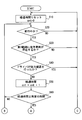
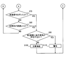
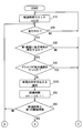
- FIG. 2 is a flowchart illustrating an example of a process flow in the ECU according to the first embodiment.
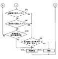
- FIG. 3 is a flowchart illustrating an example of a process flow in the ECU according to the first embodiment.
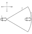
- FIG. 4 is a diagram illustrating an example of a first range according to the first embodiment.
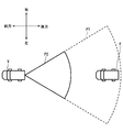
- FIG. 5 is a diagram illustrating an example of an arrangement relationship between the first range and the second range according to the first embodiment.
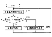
- FIG. 6 is a flowchart showing processing for determining deceleration of the host vehicle according to the first embodiment.
- FIG. 7 is a flowchart showing a process for determining a determination period of deceleration determination according to the second embodiment.
- FIG. 8 is a flowchart showing an example of a process flow in the ECU according to the third embodiment.
- FIG. 9 is a flowchart illustrating an example of a process flow in the ECU according to the third embodiment.
- the driving support device 1 is mounted on the host vehicle V, which is an automobile, and notifies the driver of the host vehicle V which will be described later.
- the driving support device 1 includes a traveling state detection unit 2, a rear detection sensor 3, a confirmation operation detection unit 4, a deceleration detection unit 5, a notification device 6, and an ECU 7.
- the deceleration detection unit 5 is connected to the accelerator pedal 8 and the brake pedal 9.
- the traveling state detection unit 2 detects the traveling state of the host vehicle V and outputs it to the ECU 7 described later.
- the traveling state means whether the host vehicle V is traveling or is stopped. Moreover, about the state which is drive
- a speed sensor can be used to calculate the speed of the host vehicle V.
- a speed sensor a sensor that detects the rotational speed of an axle by a pulse generator attached to the axle of the own vehicle V and calculates the speed of the own vehicle V based on the detected rotational speed is known.
- An acceleration sensor can be used for calculating the acceleration of the host vehicle V.
- the acceleration sensor is preferably attached to the vehicle body of the host vehicle V and detects acceleration generated by the acceleration / deceleration of the host vehicle V.
- the traveling state detection unit 2 detects the speed or acceleration value of the host vehicle V as the host vehicle V travels by using a vehicle speed sensor or an acceleration sensor.
- the traveling state detection unit 2 corresponds to a traveling state detection unit.
- the rear detection sensor 3 detects the presence or absence of a moving object behind the host vehicle V and outputs it to the ECU 7 described later.
- a moving object here is not restricted to vehicles, such as a motor vehicle and a two-wheeled vehicle, for example, but also includes a pedestrian.
- a rear vehicle R an example in which the moving object is an automobile will be described, and for the sake of convenience, it will be referred to as a rear vehicle R hereinafter.
- the rear detection sensor 3 corresponds to a rear situation detection unit.
- the rear detection sensor 3 detects not only the presence or absence of the rear vehicle R but also the relative positional relationship between the host vehicle V and the rear vehicle R, and outputs it to the ECU 7 described later.
- the relative positional relationship here may be the distance between the host vehicle V and the rear vehicle R, the direction in which the rear vehicle R exists with respect to the traveling direction of the host vehicle V, or the like.
- a radar sensor or sonar can be used to calculate the distance between the host vehicle V and the rear vehicle R and the direction in which the rear vehicle R exists. When the distance between the host vehicle V and the rear vehicle R and the direction in which the rear vehicle R exists are calculated, the presence / absence of an object behind the host vehicle V is also detected.
- the radar sensor for example, a so-called millimeter wave radar device using millimeter wave radio waves can be used.
- the millimeter wave radar apparatus scans a substantially fan-shaped range by providing two or more receiving antennas having different directivities at the center of the rear end of the host vehicle V and receiving a reflected wave with respect to the transmitted millimeter wave. Those are preferred.
- the sonar receives ultrasonic waves from two sets of transducers attached to the rear bumper of the host vehicle V at a predetermined distance to receive reflected waves from the object, and from transmission to reception. It is only necessary to calculate the distance from each transducer to the object by measuring the time between.
- a radar sensor or sonar used for detecting the relative positional relationship between the host vehicle V and the rear vehicle R corresponds to the relative position calculation unit.
- the confirmation operation detection unit 4 detects a rear confirmation state by the driver of the host vehicle V and outputs it to the ECU 7 described later.
- the rear confirmation state indicates the presence or absence of a rear confirmation operation such as an operation in which the driver visually observes the rearview mirror or the side mirror, or direct observation by facing the rear.
- the detection of the backward confirmation situation can be performed by, for example, photographing the driver's face from the opposite direction and extracting the face direction and the line-of-sight direction from the photographed image. In order to photograph the driver's face, it is preferable to use a camera disposed near the front of the driver's seat, for example, near the meter or on the steering column.
- a known extraction algorithm can be used as a method for extracting the driver's face direction and line-of-sight direction from the captured image.
- the backward confirmation operation to be detected is not limited to these.
- a camera (not shown) is arranged outside the own vehicle V, and an image showing the rear situation captured by the camera is arranged in the own vehicle V.
- the display device (not shown) may be projected, and the display device may be detected by the driver.
- the confirmation operation detection unit 4 corresponds to a confirmation operation detection unit.
- the deceleration detection unit 5 detects deceleration of the host vehicle V and outputs it to the ECU 7 described later.
- the deceleration detection unit 5 is configured to be connectable to at least one of the accelerator pedal 8 and the brake pedal 9.
- the deceleration of the host vehicle V here may be a case where the driver decelerates as a result of a driving operation intended to decelerate, or a case where the host vehicle V decelerates due to a road surface on which the host vehicle V travels.
- the deceleration detection unit 5 includes a deceleration operation detection unit that detects a deceleration operation that is a driving operation intended for deceleration performed by the driver.
- the driving operation intended for deceleration performed by the driver includes, for example, a case where the accelerator pedal 8 is depressed and a case where the brake pedal 9 is depressed.
- a known accelerator position sensor that detects the position of the accelerator pedal 8 using a Hall IC or the like can be used.
- a stroke sensor that measures the stroke amount of the brake pedal 9 can be used to detect an operation on the brake pedal 9.
- This deceleration operation detection unit corresponds to the deceleration operation detection unit.
- the deceleration detection unit 5 corresponds to a deceleration detection unit.
- the notification device 6 is arranged in the host vehicle V and notifies the driver.
- the notification may be performed using, for example, display, sound, vibration, etc. so that the driver's attention can be drawn. More specifically, for example, a vehicle-mounted display, a HUD unit, a speaker, a buzzer, an LED, a vibrator embedded in a vehicle seat or a steering wheel, or the like used in a navigation device (not shown) can be used.
- This notification device 6 corresponds to a notification unit.
- Alerting is used when the current situation does not immediately lead to an accident, but alerts the driver.
- a notification for example, a voice message such as “There is a vehicle behind.
- a warning is an immediate response from the driver when, for example, the distance between the host vehicle V and the rear vehicle R is short and the host vehicle V is decelerated and there is a high possibility of a collision with the rear vehicle R. Used when is required. As notification in this case, it is necessary to give a stimulus stronger than alerting the driver. It can be used to give vibration.
- the ECU (Electronic Control Unit) 7 includes a CPU and various memories (not shown), and is based on inputs from the above-described traveling state detection unit 2, rear detection sensor 3, confirmation operation detection unit 4, and deceleration detection unit 5. Then, a series of processes related to notification to the driver is executed.
- This ECU 7 corresponds to a control unit.
- ECU7 judges whether the own vehicle V is drive
- FIG. When the determination is made based on the speed of the host vehicle V, it can be determined that the vehicle is traveling when the speed of the host vehicle V detected by the speed sensor is greater than 0 km / h. Further, it is possible to determine whether or not the host vehicle V is traveling from the acceleration of the host vehicle V detected by the acceleration sensor.
- the ECU 7 determines whether or not the driver appropriately confirms the backward direction based on the driver's backward confirmation status input from the confirmation operation detection unit 4. Specifically, the elapsed time from the last time the driver confirmed the rear to the present is measured, and if the elapsed time is equal to or longer than the predetermined time, it is determined that the driver has not properly confirmed the rear. To do.
- step S20 it is determined whether or not the host vehicle V is traveling. If it is determined that the vehicle is not running, the process returns to step S10. If it is determined that the vehicle is traveling, the process proceeds to step S30.
- step S30 based on the input from the rear detection sensor 3, it is determined whether or not the rear vehicle R exists in the first range P1 shown in FIG.
- the first range P1 is a range in which the driver should check the presence or absence of the rear vehicle R. More specifically, the 1st range P1 is provided in the fan shape centering on the rear end of the own vehicle V, and the radius is set to 30 m. However, the radius of the first range P1 is not limited to 30 m, and may be determined according to the vehicle as appropriate. If it is determined that there is no rear vehicle R to be detected in the first range P1, the process returns to step S10. When it is determined that the rear vehicle R as the detection target exists in the first range P1, the process proceeds to step S40.
- step S40 it is determined whether or not the driver has confirmed the situation behind the host vehicle V based on the input from the confirmation operation detection unit 4. If it is determined that the driver has confirmed the situation behind the host vehicle V, the process returns to step S10. If it is determined that the driver has not confirmed the situation behind the host vehicle V, the process proceeds to step S50.
- step S50 the count is added to the counter cnt. Then, after performing the addition process, the process proceeds to step S60.
- the counter cnt is in a state where the host vehicle V is traveling, the rear vehicle R exists in the first range P1 behind the host vehicle V, and the driver has not confirmed the rear. It will indicate the duration.
- step S60 it is determined whether or not the counter cnt has reached a predetermined time.
- the predetermined time is set to a value corresponding to 5 seconds.
- the predetermined time is not limited to this, and may be determined appropriately in consideration of vehicle conditions and the like. If the counter cnt is smaller than the predetermined time as a result of the determination, the process returns to step S20. If the counter cnt is equal to or longer than the predetermined time, the process proceeds to step S70.
- step S70 based on the input from the deceleration detecting unit 5, it is determined whether or not the driver has performed a deceleration operation. Based on the detected depression amount of the accelerator pedal 8, when the driver loosens the depression amount of the accelerator pedal 8, it is determined that the driver has performed a deceleration operation. Further, when determining based on the brake operation, when the stroke amount of the brake pedal 9 is increased and it is determined that the brake pedal 9 is depressed, it is determined that the driver has performed a deceleration operation. If it is determined that the deceleration operation is not performed, the process proceeds to step S80. If it is determined that the deceleration operation has been performed, the process proceeds to step S90.
- step S80 based on the input from the deceleration detection unit 5, it is determined whether or not the speed of the host vehicle V has actually decreased.
- the determination is made based on the temporal change in the speed of the host vehicle V derived from the detection result of the traveling state detection unit 2. More specifically, the determination is made using a deceleration determination flow described later. If it is determined that the speed of the host vehicle V has decreased, the process proceeds to step S90. If it is determined that the speed of the host vehicle V has not decreased, the process returns to step S20.
- the state in which the host vehicle V is traveling, the rear vehicle R exists in the first range P1 behind the host vehicle V, and the driver has not confirmed the rear is predetermined. If the driver performs a deceleration operation or the speed of the host vehicle V decreases while the time continues, the process proceeds to step S90.
- step S90 based on the input from the rear detection sensor 3, the presence / absence of the rear vehicle R in the second range P2, which is a partial range close to the host vehicle V in the first range P1, is determined.
- the second range P2 is provided in a fan shape centered on the rear end of the host vehicle V in the first range P1 described above, and its radius is in a range of 10 m. Is set. However, the radius of the second range P2 is not limited to 10 m, and may be determined according to the vehicle as appropriate.
- the determination in step S90 is performed when the rear vehicle R exists in the first range P1.
- step S90 is that the relative positional relationship between the host vehicle V and the rear vehicle R, in particular, the relative distance is equal to or smaller than the radius of the second range P2, or the relative distance is within the second range P2. It is determined whether the distance is longer than the radius and shorter than the radius of the first range P1.
- step S100 If it is determined that the rear vehicle R does not exist in the second range P2, the process proceeds to step S100. If it is determined in step S90 that the rear vehicle R exists in the second range P2, the process proceeds to step S110.
- step S100 the notification device 6 alerts the driver as described above.
- step S110 the notification device 6 gives the above warning to the driver.
- step S80 the deceleration determination of the host vehicle V performed in step S80 will be described in detail with reference to FIG.
- the flow shown in FIG. 6 is always repeatedly executed on the ECU 7 in parallel with the main flow shown in FIGS.
- step S210 the speed of the host vehicle V is detected based on the input from the traveling state detection unit 2. And it records on the recording part which is not shown in figure provided in ECU7.
- This recording unit is configured by a so-called ring buffer that records input values in the input order and sequentially overwrites the oldest values when the recording content reaches a set upper limit.
- step S220 the latest speed value and the next new speed value are read from the recording unit described above and compared. As a result of the comparison, if the speed is decreasing, the process proceeds to step S230 and it is determined that the host vehicle V has decelerated. As a result of the comparison, if the speed has not changed or has increased, the process proceeds to step S240 and it is determined that the host vehicle V has not decelerated.
- the recording unit described above preferably uses a volatile recording medium that retains a value only while the ECU 7 is energized.
- a volatile recording medium when a volatile recording medium is used, when the determination in step S220 is performed immediately after the start of energization of the ECU 7, only one speed of the host vehicle V is recorded, so that comparison cannot be performed. In such a case, it can be considered that at least the host vehicle V is decelerating, and therefore the process may proceed to step S240.
- the host vehicle V is traveling, the rear vehicle R exists within a predetermined range set behind the host vehicle V, and the driver performs a predetermined time.
- the driver is notified. Therefore, the driver receives a notification when the host vehicle V decelerates in a dangerous situation in which confirmation for the rear is neglected.
- the driver is not excessively notified, and troublesomeness for the driver can be reduced.
- the danger can be reduced at the same time.
- the deceleration of the host vehicle V is determined in two stages: a deceleration operation by the driver and a decrease in the speed of the host vehicle V.
- the structure of 1st Embodiment determines whether alerting alerting
- the traveling state detection unit 2 in the second embodiment detects or calculates the speed or acceleration associated with traveling of the host vehicle V, and in addition, detects the inclination angle of the host vehicle V with respect to the horizontal plane. Detect or calculate. And the determination period of the deceleration determination of the own vehicle V shown in FIG. 6 demonstrated in 1st Embodiment is determined based on the detected inclination angle.
- the traveling state detection unit 2 in the second embodiment includes an inclination angle sensor (not shown) in order to detect or calculate the inclination angle of the host vehicle V with respect to the horizontal plane.
- a well-known gyro sensor can be used as the tilt angle sensor here.
- a known detection algorithm can be used.
- step S310 the tilt angle of the host vehicle V with respect to the horizontal direction is detected based on the input from the tilt angle sensor.
- the inclination angle here is an angle between a virtual straight line connecting the front wheel and the rear wheel of the host vehicle V and the horizontal direction.
- step S320 the inclination angle detected in step S310 is compared with a predetermined threshold value to determine whether the inclination angle is larger than the predetermined threshold value.
- the predetermined threshold is set to 6 degrees.
- the threshold value is not limited to 6 degrees, and may be appropriately determined in consideration of vehicle conditions and the like.
- a predetermined determination period t1 is set as a determination period for deceleration determination.
- the determination cycle t1 is set to 0.5 seconds.
- step S340 a predetermined determination cycle t2 that is longer than the above-described determination cycle t1 is set as the determination cycle for deceleration determination.
- the determination cycle t2 is set to 1 second.
- the determination cycle of the deceleration determination is set shorter than when it is small.
- the speed of the host vehicle V tends to decrease as the slope of the uphill increases.
- the determination cycle of the deceleration determination is shortened.
- the processing load in the ECU 7 can be reduced by lengthening the determination cycle of the deceleration determination.
- the notification indicating the presence of the vehicle is a notification for indicating that the rear vehicle R is present behind the host vehicle V.
- the alert and warning are alerts and warnings for informing the driver that there is a risk of contact between the host vehicle V and the rear vehicle R.
- a timing for notifying the driver of alerting is added.
- the notification that the vehicle is present is immediately sent to the driver when the driver is not aware of the rear vehicle R.
- the state in which the driver is not aware of the rear vehicle R is a state in which the host vehicle V is traveling, the rear vehicle R exists in the first range, and the driver has not confirmed the rear.
- “immediately” here means that, as shown in FIG. 8, after determining whether or not the driver has confirmed backward in S40, notification is executed in the next process (S120) in which the determination is NO. It means to do.
- the time interval for executing S120 after executing S40 is shorter than the elapse of the predetermined time used in step S60 of the first embodiment after it is determined that the driver does not perform backward confirmation. Become.
- the notification indicating the presence of the vehicle displays an icon or the like on, for example, an in-vehicle display or a HUD unit used in a navigation device (not shown).
- a notification instead of a voice notification
- the display may be reduced, or the display color may be inconspicuous.
- the volume of the notification may be lower than the alert or a short voice message.
- the predetermined time used in step S60 of the first embodiment is set as the first threshold time, and the alert detection is performed by the deceleration detection unit 5 in a state in which the first vehicle has not noticed the rear vehicle R and the first threshold time has elapsed.
- the alert detection is performed by the deceleration detection unit 5 in a state in which the first vehicle has not noticed the rear vehicle R and the first threshold time has elapsed.
- deceleration of the vehicle V is detected, it is performed to the driver.
- alerting is performed to the driver when the second threshold time, which is longer than the first threshold time, has elapsed in a state in which the rear vehicle R is not aware.
- the second threshold time is a time determined from this viewpoint, the second threshold time is set to be longer than the first threshold time.
- the driver can be informed that there is a risk of contact between the host vehicle V and the rear vehicle R. And by performing alerting, the possibility that the host vehicle V and the rear vehicle R will contact each other can be reduced.
- step S40 If it is determined in step S40 that the driver has not confirmed the situation behind the host vehicle V, the process proceeds to step S120.
- step S120 it is determined that the driver is not aware of the rear vehicle R, and the driver is notified of the presence of the vehicle. After step S120, the process proceeds to step S50.
- step S80 if it is determined that the speed of the host vehicle V has not decreased, the process proceeds to step S130.
- step S130 it is determined whether or not the counter cnt indicating the elapsed time is equal to or greater than the second threshold time.
- the second threshold time is set to a value corresponding to 20 seconds.
- the second threshold time is not limited to this, and may be appropriately determined in consideration of vehicle conditions and the like as long as it is longer than the first threshold time.
- the process returns to step S20. If the counter cnt is equal to or longer than the second threshold time, the process proceeds to step S100.
- step S130 the state in which the driver is not aware of the rear vehicle R continues for the first threshold time or longer, and even if the deceleration detection unit 5 has not detected the deceleration of the host vehicle V, the second When the threshold time has elapsed, the driver is alerted.
- one of two types of determination periods is set by one determination as to whether or not the inclination angle is larger than a predetermined threshold.
- the determination cycle may be changed depending on the value of the inclination angle.
- the determination period of the deceleration determination may be set shorter as the inclination angle of the host vehicle V with respect to the horizontal plane becomes steeper.
- a biaxial or triaxial acceleration sensor for detecting at least biaxial acceleration in the vehicle longitudinal direction and the vehicle vertical direction may be used. If this acceleration sensor is used, the angle between the direction in which the gravitational acceleration is generated and the vehicle longitudinal direction can be detected. Since the direction in which the gravitational acceleration occurs is a direction perpendicular to the horizontal plane, the inclination angle of the host vehicle V with respect to the horizontal plane can be detected using this acceleration sensor.
- each section is expressed as S10, for example.
- each section can be divided into a plurality of subsections, while a plurality of sections can be combined into one section.
- each section configured in this manner can be referred to as a device, module, or means.
Landscapes
- Physics & Mathematics (AREA)
- General Physics & Mathematics (AREA)
- Traffic Control Systems (AREA)
Abstract
運転支援装置は、自車両(V)の走行状態検出部(2)と、前記自車両後方の移動物体に関する状況を検出する後方状況検出部(3)と、前記自車両のドライバによる、前記自車両後方に対する確認動作を検出する確認動作検出部(4)と、前記自車両の減速を検出する減速検出部(5)と、前記ドライバに対して報知を行う報知部(6)と、前記自車両が走行状態であり、且つ前記自車両後方の所定範囲内に前記移動物体が存在し、且つ前記ドライバが後方確認を行っていない状況が所定の時間継続しているときに、前記自車両が減速した場合には、前記報知部によって前記ドライバに報知させる制御部(7)と、を備える。
Description
本出願は、2016年6月2日に出願された日本特許出願番号2016-110863号および2017年3月15日に出願された日本特許出願番号2017-050297号基づくもので、ここにその記載内容を援用する。
本開示は、運転支援装置に関するものである。
従来、自車両の後方状況について、ドライバに注意を促す技術が知られている。例えば、特許文献1には、自車両の後方に他車両が存在し、自車両のドライバがその他車両を認知していないと考えられる場合に、ドライバに対して注意喚起を行う技術が開示されている。
特許文献1に開示の技術では、自車両の後方に位置する他車両の、位置や速度などの状態が変化する度にドライバに対して注意喚起を行うこととなる。よって、道路状況によっては、必要以上に注意喚起が実行され、ドライバに煩わしさを感じさせる可能性がある。
本開示は、ドライバにとっての煩わしさの低減と、後方確認を怠ることによる危険性の低減とを両立した、運転支援装置を提供することを目的とする。
本開示の態様において、運転支援装置は、自車両の走行状態を検出する走行状態検出部と、前記自車両後方の所定範囲内における前記自車両以外の移動物体に関する状況を検出する後方状況検出部と、前記自車両のドライバによる、前記自車両後方に対する確認動作を検出する確認動作検出部と、前記自車両の減速を検出する減速検出部と、前記ドライバに対して報知を行う報知部と、前記走行状態検出部と、前記後方状況検出部と、前記確認動作検出部の検出結果に基づいて、前記自車両が走行状態であり、且つ前記自車両後方の所定範囲内に前記移動物体が存在し、且つ前記ドライバが後方確認を行っていない状況が所定の時間継続しているときに、前記減速検出部によって前記自車両の減速が検出された場合には、前記報知部によって前記ドライバに報知させる制御部とを備える。
上記の運転支援装置では、減速前の自車両後方に対する安全確認が成されていないと考えられる状況で、自車両が減速する場合に、ドライバに対して報知を行う。よって、ドライバが自車両後方に対する安全確認を行っている場合には報知が行われないので、後方確認を怠ることによる危険性を低減しながらも、ドライバにとっての煩わしさを低減することができる。
本開示についての上記目的およびその他の目的、特徴や利点は、添付の図面を参照しながら下記の詳細な記述により、より明確になる。その図面は、
図1は、第1実施形態に係る運転支援装置の概略的な構成の一例を示す図であり、
図2は、第1実施形態に係るECUでの処理の流れの一例を示すフローチャートであり、
図3は、第1実施形態に係るECUでの処理の流れの一例を示すフローチャートであり、
図4は、第1実施形態に係る第1範囲の一例を示す図であり、
図5は、第1実施形態に係る第1範囲と第2範囲との配置関係の一例を示す図であり、
図6は、第1実施形態に係る自車両の減速判定の処理を示すフローチャートであり、
図7は、第2実施形態に係る減速判定の判定周期を決定する処理を示すフローチャートであり、
図8は、第3実施形態に係るECUでの処理の流れの一例を示すフローチャートであり、
図9は、第3実施形態に係るECUでの処理の流れの一例を示すフローチャートである。
図面を参照しながら、開示のための複数の実施形態及び変形例を説明する。尚、説明の便宜上、複数の実施形態及び変形例の間において、それまでの説明に用いた図に示した部分と同一の機能を有する部分については、同一の符号を付し、その説明を省略する場合がある。同一の符号を付した部分については、他の実施形態及び/又は変形例における説明を参照することができる。また、特段の説明がない限り、説明で用いる前方、後方などの方向指示は、自車両を運転するドライバにとっての前後及び左右方向を基準としている。
[第1実施形態]
以下、第1実施形態について、図面を用いて説明する。
以下、第1実施形態について、図面を用いて説明する。
運転支援装置1は、自動車である自車両Vに搭載されており、自車両Vのドライバに対して後述する報知を行うものである。
図1に示すように、運転支援装置1は、走行状態検出部2、後方検出センサ3、確認動作検出部4、減速検出部5、報知装置6、ECU7を備えている。そして、減速検出部5は、アクセルペダル8およびブレーキペダル9と接続されている。
走行状態検出部2は、自車両Vの走行状態を検出し、後述するECU7へと出力する。ここでの走行状態とは、自車両Vが走行している状態、および、停車している状態のいずれであるかを意味する。また、走行している状態については、前進走行しているか、後進走行しているかを区別する。
この走行状態を検出するために、自車両Vの走行に伴う、速度または加速度を検出あるいは算出する。自車両Vの速度の算出には、例えば速度センサを用いることができる。速度センサとしては自車両Vの車軸に取り付けられたパルス発生器によって該車軸の回転速度を検出し、検出した回転速度に基づいて自車両Vの速度を算出するものが知られている。また、自車両Vの加速度の算出には、加速度センサを用いることができる。加速度センサは、自車両Vの車体に取り付けられ、自車両Vが加減速することによって生じる加速度を検出するものが好適である。走行状態検出部2は、車速センサまたは加速度センサを用いることで、自車両Vの走行に伴う、自車両Vの速度または加速度の値を検出する。
速度がゼロであれば、自車両Vが停止している状態であるとすることができる。また、一定時間、車両前後方向の加速度に変化がない場合にも、自車両Vが停止しているとすることができる。自車両Vが走行している場合、ほぼ速度一定となる状態はあっても、完全に速度一定で運転することは困難である。したがって、車両前後方向の加速度に変化がない場合にも、自車両Vが停止しているとすることができるのである。自車両Vが走行している状態において、その走行が前進であるか後進であるかは、たとえば、シフトポジションから判断する。この走行状態検出部2が、走行状態検出部に相当する。
後方検出センサ3は、自車両Vの後方における移動物体の有無を検出し、後述するECU7へと出力するものである。ここでの移動物体とは、例えば自動車や二輪車などの車両に限られるものではなく、歩行者をも含むものである。尚、本実施形態では移動物体が自動車である例を説明し、便宜上、以降では後方車両Rと呼ぶこととする。この後方検出センサ3が、後方状況検出部に相当する。
また、後方検出センサ3は、後方車両Rの有無だけではなく、自車両Vと後方車両Rとの相対的な位置関係も検出し、後述するECU7へと出力するものである。ここでの相対的な位置関係とは、自車両Vと後方車両Rとの間の距離や、自車両Vの進行方向に対して後方車両Rが存在する方位などが考えられる。尚、自車両Vと後方車両Rとの間の距離、及び後方車両Rが存在する方位の算出には、例えばレーダセンサやソナーを用いることができる。自車両Vと後方車両Rとの間の距離、及び後方車両Rが存在する方位の算出をした場合には、自車両Vの後方における物体の有無の検出も行ったことになる。
レーダセンサは、例えばミリ波帯の電波を用いた、いわゆるミリ波レーダ装置を用いることができる。ミリ波レーダ装置は、それぞれ異なる指向性を有した2以上の受信アンテナを自車両Vの後端中央に設け、送信したミリ波に対する反射波を受信することで、略扇形状の範囲を走査するものが好適である。またソナーは、自車両Vのリアバンパに、所定の距離を空けて取り付けられた2組の送受波器からそれぞれ超音波をパルス送信して対象物からの反射波を受信し、その送信から受信までの間の時間を測定することにより、それぞれの送受波器から対象物までの距離を算出するものであればよい。そして算出した距離を用いて、いわゆる三角測量を行うことにより、対象物の自車両Vに対する相対位置を測定するように構成されたものであればよい。尚、自車両Vと後方車両Rとの相対的な位置関係の検出に用いられたレーダセンサまたはソナーが相対位置算出部に相当する。
確認動作検出部4は、自車両Vのドライバによる後方確認状況を検出し、後述するECU7へと出力するものである。ここでの後方確認状況とは、例えばドライバがバックミラーやサイドミラーを目視する動作や、または自ら後方を向いて直接目視するなどの後方確認動作の有無を示すものである。この後方確認状況の検出は、例えばドライバの顔を対向方向から撮影し、その撮影画像から顔の向きや、視線の向きを抽出することで行うことができる。ドライバの顔を撮影するためには、例えばメータ付近やステアリングコラム上などの運転席の正面に近い位置に配置したカメラを用いると好適である。尚、撮影した画像からドライバの顔の向きや視線の向きを抽出する手法については、周知の抽出アルゴリズムを用いることができる。また、検出すべき後方確認動作はこれらに限られるものではなく、例えば自車両Vの外部に図示しないカメラを配置し、このカメラによって撮像された後方状況を示す画像を、自車両V内に配置した図示しない表示装置に投影させ、この表示装置をドライバが確認する行為を検出するようにしてもよい。この確認動作検出部4が、確認動作検出部に相当する。
減速検出部5は、自車両Vの減速を検出し、後述するECU7へと出力するものである。そして減速検出部5は、アクセルペダル8またはブレーキペダル9の少なくとも一方と接続可能に構成されている。ここでの自車両Vの減速とは、ドライバが減速を意図した運転操作を行った結果として減速する場合と、自車両Vが走行する路面等が要因で減速する場合が考えられる。
減速検出部5は、ドライバが行う減速を意図した運転操作である減速操作を検出する減速操作検出部を備えている。ドライバが行う減速を意図した運転操作としては、例えばアクセルペダル8の踏み込み具合を緩めた場合や、ブレーキペダル9を踏んだ場合などが含まれる。尚、アクセルペダル8の踏込量の検出には、ホールIC等を用いてアクセルペダル8の位置を検出する、周知のアクセルポジションセンサを用いることができる。また、ブレーキペダル9に対する操作の検出には、ブレーキペダル9のストローク量を計測するストロークセンサを用いることができる。この減速操作検出部が減速操作検出部に相当する。
次に、走行する路面等が要因で自車両Vが減速する場合としては、例えば走行中に上り坂に差し掛かり、道路勾配が大きくなった際が考えられる。このような外部要因による減速については、自車両Vの速度や加速度の時間変化に基づいて検出することができる。尚、自車両Vの速度や加速度については、前述した走行状態検出部2の検出結果を用いれば良い。この減速検出部5が、減速検出部に相当する。
報知装置6は、自車両V内に配置され、ドライバに対して報知を行う。報知としては、運転中のドライバの注意を引くことができるよう、例えば表示や音、振動などを用いて行うと良い。より具体的には、例えば図示しないナビゲーション装置等で利用される車載ディスプレイやHUDユニット、スピーカー、ブザー、LED、車両シートやステアリングホイールに埋設されたバイブレータ等を用いることができる。この報知装置6が、報知部に相当する。
報知は、その緊急度に応じて、「注意喚起」と、注意喚起よりも緊急度が高い「警告」の2種類が設定されている。
注意喚起とは、現在の状況がすぐには事故につながらないものの、ドライバに注意を促す場合に用いられる。この場合の報知としては、例えば「後方に車両がいます。注意しましょう。」などのような音声メッセージを出力すると良い。
警告とは、例えば自車両Vと後方車両Rとの間の距離が短く、自車両Vが減速することによって、後方車両Rとの衝突発生の可能性が高い場合など、ドライバの即急な対応が求められる場合に用いられる。この場合の報知としては、ドライバに対して注意喚起よりも強い刺激を与える必要があり、例えばブザーを吹鳴させる、HUDやLED等を用いてドライバの目前で発光や明滅動作を行う、或いはバイブレータを用いて振動を与える、などが考えられる。
ECU(Electronic Control Unit)7は、図示しないCPU及び各種メモリ等を含んで構成され、前述した走行状態検出部2、後方検出センサ3、確認動作検出部4、減速検出部5からの入力に基づいて、ドライバへの報知に関わる一連の処理を実行する。このECU7が、制御部に相当する。
ECU7は、走行状態検出部2からの入力に基づいて、自車両Vが走行中であるか否かを判断する。自車両Vの速度に基づいて判断を行う場合には、速度センサで検出した自車両Vの速度が0km/hより大きいときに走行中であると判断することができる。また、加速度センサで検出した自車両Vの加速度からも自車両Vが走行中か否かを判断することが可能である。
ECU7は、後方検出センサ3からの入力に基づいて、検出された後方車両Rが、後述する所定の範囲内に存在するか否かを判断する。
ECU7は、確認動作検出部4から入力されたドライバの後方確認状況に基づいて、ドライバが後方に対する確認を適切に行っているかどうかを判断する。具体的には、ドライバが最後に後方を確認したときから現在までの経過時間を計測し、その経過時間が所定時間以上である場合に、ドライバが後方に対する確認を適切に行っていないものと判断する。
続いて、ECU7で実行される一連の処理を、図2および図3に示すフローチャートを用いて説明する。
まずステップS10では、ドライバが最後に後方確認を行ってからの経過時間をカウントするためのカウンタcntを0にリセット(cnt=0)する。
次にステップS20では、自車両Vが走行中か否かを判断する。走行中ではないと判断された場合には、ステップS10に戻る。走行中であると判断された場合には、ステップS30へと移行する。
ステップS30では、後方検出センサ3からの入力に基づいて、図4に示す第1範囲P1内に、後方車両Rが存在するか否かを判断する。第1範囲P1は、ドライバが後方車両Rの有無を確認すべき範囲である。より具体的には、第1範囲P1は、自車両Vの後端を中心とした扇形状に設けられており、その半径は30mに設定されている。但し、第1範囲P1の半径は30mに限定されるものではなく、適宜車両に合わせて定めれば良い。第1範囲P1の中に検出対象である後方車両Rが存在しないと判断された場合には、ステップS10に戻る。第1範囲P1の中に検出対象である後方車両Rが存在すると判断された場合には、ステップS40へと移行する。
ステップS40では、確認動作検出部4からの入力に基づいて、ドライバが自車両Vの後方の状況に対する確認を行ったか否かを判断する。ドライバが自車両Vの後方の状況に対する確認を行ったと判断された場合には、ステップS10に戻る。ドライバが自車両Vの後方の状況に対する確認を行わなかったと判断された場合には、ステップS50へと移行する。
ステップS50では、カウンタcntに対して、カウントを加算する。そして、加算処理を行った後に、ステップS60へと移行する。ここで、ステップS20からステップS50の処理が一周する度にカウンタcntに加算されることになる。これにより、カウンタcntは、自車両Vが走行中であり、且つ自車両Vの後方である第1範囲P1の中に後方車両Rが存在し、且つドライバが後方の確認を行っていない状態の継続時間を示すこととなる。
ステップS60では、カウンタcntが所定の時間以上となったか否かを判断する。ここでは、所定の時間は5秒に対応する値に設定されている。但し、所定の時間はこれに限定されるものではなく、車両条件等を考慮し、適宜定めれば良い。判断の結果、カウンタcntが所定の時間より小さい場合には、ステップS20に戻る。そしてカウンタcntが所定の時間以上の場合には、ステップS70へと移行する。
ステップS70では、減速検出部5からの入力に基づいて、ドライバが減速操作を行ったか否かを判断する。検出されたアクセルペダル8の踏み込み量に基づいて、ドライバがアクセルペダル8の踏み込み具合を緩めた場合に、ドライバが減速操作を行ったと判断する。また、ブレーキ操作に基づいて判断する場合には、ブレーキペダル9のストローク量が増加し、ブレーキペダル9が踏み込まれたと判断される場合に、ドライバが減速操作を行ったと判断する。減速操作が行われていないと判断される場合にはステップS80へと移行する。また、減速操作が行われたと判断される場合には、ステップS90へと移行する。
次のステップS80では、減速検出部5からの入力に基づいて、自車両Vの速度が実際に減少したか否かを判断する。ここでは前述したとおり、走行状態検出部2の検出結果から導出した自車両Vの速度の時間変化に基づいて判断を行う。より具体的には、後述する減速判定フローを用いて判断を行う。自車両Vの速度が減少したと判断される場合には、ステップS90へと移行する。自車両Vの速度が減少していないと判断された場合には、ステップS20に戻る。
ここまでの処理によって、自車両Vが走行中であり、且つ自車両Vの後方である第1範囲P1の中に後方車両Rが存在し、且つドライバが後方の確認を行っていない状態が所定時間継続している状況で、ドライバが減速操作を行ったか、自車両Vの速度が減少した場合に、ステップS90へと移行することになる。
続いてステップS90では、後方検出センサ3からの入力に基づいて、前述の第1範囲P1の中でも自車両Vに近い一部の範囲である第2範囲P2における後方車両Rの有無を判断する。第2範囲P2は、図5に示される通り、前述の第1範囲P1の中であって、自車両Vの後端を中心とした扇形状に設けられており、その半径は10mの範囲に設定されている。但し、第2範囲P2の半径は10mに限定されるものではなく、適宜車両に合わせて定めれば良い。このステップS90の判断は、後方車両Rが第1範囲P1に存在している場合に行う。よって、ステップS90の判断は、自車両Vと後方車両Rの相対的な位置関係、特に相対距離が、第2範囲P2の半径以下であるか、あるいは、その相対距離が、第2範囲P2の半径よりも長く、且つ、第1範囲P1の半径よりも短い距離であるかを判断している。
第2範囲P2の中に後方車両Rが存在しないと判断された場合には、ステップS100へと移行する。また、ステップS90で第2範囲P2の中に後方車両Rが存在すると判断された場合には、ステップS110へと移行する。
ステップS100では、報知装置6からドライバに対して、前述の注意喚起を行う。またステップS110では、報知装置6からドライバに対して、前述の警告を行う。
続いて、ステップS80で行われる、自車両Vの減速判定について、図6を用いて詳述する。尚、図6に示されるフローは、図2および図3に示されるメインフローと並行して、ECU7上で常に繰り返し実行されるものである。
まずステップS210では、走行状態検出部2からの入力に基づいて自車両Vの速度を検出する。そして、ECU7に設けられた図示しない記録部に記録する。この記録部は、入力された値を入力された順序で記録し、記録内容が設定された上限に達すると、最も古い値に順次上書きを行う、いわゆるリングバッファで構成されている。記録部に検出した自車両Vの速度を記録した後に、ステップS220へと移行する。
ステップS220では、前述した記録部から、最も新しい速度値と、その次に新しい速度値とを読み込み、比較を行う。比較を行った結果、速度が減少している場合にはステップS230に移行すると共に、自車両Vが減速したと判断する。また、比較を行った結果、速度が変化していない、又は増加している場合には、ステップS240に移行すると共に、自車両Vは減速していないと判断する。
尚、前述した記録部はECU7の通電中のみ値を保持する、揮発性の記録媒体を用いることが好ましい。揮発性の記録媒体を用いる場合には、ECU7の通電開始直後にステップS220の判断を行う際、自車両Vの速度が1つのみ記録されている状態であるため、比較を行うことができない。このような場合には、少なくとも自車両Vが減速している状況とは考えられない為、ステップS240へと移行するようにすれば良い。
以上、第1実施形態の構成によれば、自車両Vが走行しており、且つ、自車両Vの後方に設定された所定の範囲内に後方車両Rが存在し、且つドライバが所定の時間、後方確認を行っていない状態で、自車両Vが減速した場合、ドライバに対して報知を行う。よって、後方に対する確認を怠っているという危険な状況で、自車両Vが減速する場合に、ドライバは報知を受けることとなる。これにより、ドライバは過剰に報知を受けることがなく、ドライバにとっての煩わしさを低減することができる。また、危険な状況に対しては適切に報知が行えるため、危険性の低減も同時に実現することができる。
また、第1実施形態の構成では、自車両Vの減速を、ドライバによる減速操作と、自車両Vの速度減少という2段階で判断している。これにより、ドライバによる減速操作を検出した場合には、自車両Vの速度に反映されるよりも前の段階で報知することができるため、より危険を低減することができる。加えて、ドライバによる減速操作に関わらず自車両Vの速度が減少した場合であってもドライバに対して報知を行うため、より確実に危険を低減することができる。
さらに、第1実施形態の構成では、自車両Vに対して、後方車両Rが第2範囲P2に存在するか否かによって注意喚起の報知を行うか、警告の報知を行うかを決定する。つまり後方車両Rが存在する範囲によって報知内容を変化させる。これにより、ドライバに対して、緊急性が高い警告の報知と注意喚起の報知とに分けて報知を行うことができる。よってドライバは報知内容によって後方車両Rとの衝突の危険性がどの程度なのか理解することができる。
[第2実施形態]
以下、第2実施形態について、図面を用いて説明する。
以下、第2実施形態について、図面を用いて説明する。
第2実施形態における走行状態検出部2は、走行状態を検出するために、自車両Vの走行に伴う、速度または加速度を検出あるいは算出するのに加えて、水平面に対する自車両Vの傾斜角を検出あるいは算出する。そして第1実施形態で説明した、図6に示す自車両Vの減速判定の判定周期を、検出した傾斜角に基づいて決定する。第2実施形態における走行状態検出部2は、水平面に対する自車両Vの傾斜角を検出あるいは算出するために、図示しない傾斜角センサを備えている。ここでの傾斜角センサとしては、例えば周知のジャイロセンサを用いることができる。そして、自車両Vの傾斜角を検出する手法については、周知の検出アルゴリズムを用いることができる。
次に、ECU7で実行される減速判定の周期決定に係る一連の処理を、図7に示すフローチャートを用いて説明する。尚、図7に示されるフローは、図2および図3に示されるメインフローと、図6に示される減速判定フローと並行して、ECU7上で常に繰り返し実行されるものである。
まずステップS310では、前述の傾斜角センサからの入力に基づいて、自車両Vの水平方向に対する傾斜角を検出する。ここでの傾斜角とは、自車両Vの前輪と後輪とを結んだ仮想の直線と、水平方向との間の角度である。
次にステップS320では、ステップS310で検出した傾斜角と、あらかじめ定められた所定の閾値と、を比較し、傾斜角が所定の閾値より大きいか否かを判断する。ここでは、所定の閾値は6度に設定されている。但し、閾値は6度に限定されるものではなく、車両条件等を考慮し、適宜定めれば良い。比較の結果、傾斜角が所定の閾値よりも大きい場合には、ステップS330へと移行する。そして傾斜角が所定の閾値以下である場合には、ステップS340へと移行する。
ステップS330では、減速判定の判定周期として、所定の判定周期t1を設定する。ここでは、判定周期t1は0.5秒に設定されている。
ステップS340では、減速判定の判定周期として、前述の判定周期t1よりも長い周期である、所定の判定周期t2を設定する。ここでは、判定周期t2は1秒に設定されている。
以上の処理により、自車両Vの水平方向に対する傾斜角が所定の閾値より大きい場合には、小さい場合に比べて減速判定の判定周期を短く設定する。
例えば平坦な道路を走行している状況から、上り坂に差し掛かった場合、上り坂の勾配が大きいほど、自車両Vの速度落ちやすい。本実施形態では、このような場合を想定し、自車両Vの傾斜角に基づいて、勾配の大きい道路に差し掛かったと考えられる場合には減速判定の判定周期を短くする。
これにより、自車両Vが減速したか否かを早期に判断できる。また、それ以外の状況においては減速判定の判定周期を長くすることで、ECU7における処理の負荷を低減することができる。
[第3実施形態]
第3実施形態では、報知装置6で行われるドライバに対する報知として「注意喚起」、「警告」に加え、「車両の存在を伝える通知」が追加される。
第3実施形態では、報知装置6で行われるドライバに対する報知として「注意喚起」、「警告」に加え、「車両の存在を伝える通知」が追加される。
車両の存在を伝える通知は、自車両Vの後方に、後方車両Rが存在していることを伝えるための通知である。一方、注意喚起および警告は、ドライバに自車両Vと後方車両Rとの接触のおそれがあることを伝えるための注意喚起および警告である。
また、第3実施形態では、ドライバに対する注意喚起の報知を行うタイミングが追加される。
車両の存在を伝える通知は、ドライバが後方車両Rに気付いていない状態となった際、即座にドライバに対して行われる。ドライバが後方車両Rに気付いていない状態とは、自車両Vが走行しており、且つ、第1の範囲に後方車両Rが存在し、且つ、ドライバが後方確認を行っていない状態である。尚、ここでの即座とは、図8に示すように、S40において、ドライバが後方確認を行ったか否かを判断した後、その判断がNOになった次の処理(S120)で通知を実行することを意味する。S40を実行してからS120を実行する時間間隔は、ドライバが後方確認行っていない状態であると判断されてから、第1実施形態のステップS60で用いた所定の時間経過するよりも短いことになる。
車両の存在を伝える通知は、例えば、図示しないナビゲーション装置等で利用される車載ディスプレイやHUDユニットにアイコン等の表示を行う。車両の存在を伝える通知を音声による通知ではなく、アイコン等の表示によって行うことで、ドライバに煩わしさを与えにくく通知を行える。注意喚起が表示または表示および音声で行われる場合には、車両の存在を伝える通知は、注意喚起の表示よりも、ドライバに煩わしさを与えにくい態様とする。たとえば、表示を小さくする、表示色を目立たない色とする等の態様とする。尚、車両の存在を伝える通知を音声で行ってもよい。注意喚起より、ドライバに煩わしさを与えにくい音声で通知すればよい。例えば、注意喚起より通知の音量を小さくする、または短い音声メッセージとすると良い。
車両の存在を伝える通知により、ドライバにとっての煩わしさを低減させつつ、自車両Vの後方に、後方車両Rが存在していることをドライバに通知することができる。
第1実施形態のステップS60で用いた所定の時間を第1の閾値時間とし、注意喚起は、後方車両Rに気付いていない状態が第1の閾値時間経過した状態で、減速検出部5により自車両Vの減速が検出された場合、ドライバに対して行われる。第3実施形態では、これに加え、注意喚起は、後方車両Rに気付いていない状態が、第1の閾値時間より長い時間である第2の閾値時間経過した場合、ドライバに対して行われる。
後方車両Rに気付いていない状態が第1の閾値時間経過した状態で、減速検出部5により自車両Vの減速が検出された場合、自車両Vと後方車両Rとの接触のおそれが高くなる場合がある。
この状態でさらに時間が経過し、後方車両Rに気付いていない状態が、第1の閾値時間より長い時間である第2の閾値時間経過した場合、第1の閾値時間経過した場合よりも、長時間ドライバが後方車両Rに気付いていない状態である。前進走行中、自車両Vが減速していない状態が継続していても、運転者は、逐次、後方車両の存在を認識しながら運転すべきである。第2の閾値時間はこの観点で定められる時間であるので、第1の閾値時間よりも長い時間に設定される。
後方車両Rに気付いていない状態が、第2の閾値時間経過した場合に注意喚起を行うことで、ドライバに自車両Vと後方車両Rとの接触のおそれがあることを伝えることができる。そして注意喚起を行うことで、自車両Vと後方車両Rとが接触するおそれを低減することができる。
次に、第3実施形態のECU7で実行される一連の処理を、図8および図9に示すフローチャートを用いて説明する。尚、第1実施形態および第2実施形態との変更点のみ記載する。
ステップS40で、ドライバが自車両Vの後方の状況に対する確認を行わなかったと判断された場合には、ステップS120へと移行する。
尚、ステップS20、S30、S40により、ドライバが後方車両Rに気付いていない状態か否かが判断される。
ステップS120では、ドライバが後方車両Rに気付いていない状態であると判断され、ドライバに対して車両の存在を伝える通知を行う。ステップS120の後、ステップS50へと移行する。
そしてステップS80では、自車両Vの速度が減少していないと判断された場合には、ステップS130へと移行する。
ステップS130では、経過時間を示すカウンタcntが第2の閾値時間以上となったか否かを判断する。ここでは、第2の閾値時間は20秒に対応する値に設定されている。但し、第2の閾値時間はこれに限定されるものではなく、第1の閾値時間よりも長い時間であれば、車両条件等を考慮し、適宜定めれば良い。判断の結果、カウンタcntが第2の閾値時間より小さい場合には、ステップS20に戻る。そしてカウンタcntが第2の閾値時間以上の場合には、ステップS100へと移行する。
ステップS130では、ドライバが後方車両Rに気付いていない状態が第1の閾値時間以上継続しており、減速検出部5が自車両Vの減速を検出していない場合であっても、第2の閾値時間以上経過した場合は、ドライバに対して注意喚起を行う。
これにより、自車両Vの減速が検出された時だけでなく、ドライバが本来確認すべき後方確認が疎かになっている場合、後方確認を行うように促すことができる。
[変形例]
この明細書における開示は、例示された実施形態に制限されない。開示は、例示された実施形態と、それらに基づく当業者による変形態様を包含する。例えば、開示は、実施形態において示された部品及び/又は要素の組み合わせに限定されない。開示は、多様な組み合わせによって実施可能である。
この明細書における開示は、例示された実施形態に制限されない。開示は、例示された実施形態と、それらに基づく当業者による変形態様を包含する。例えば、開示は、実施形態において示された部品及び/又は要素の組み合わせに限定されない。開示は、多様な組み合わせによって実施可能である。
[変形例1]
上記第1実施形態では、後方車両Rが第1範囲P1と第2範囲P2のどちらに存在するかに基づいて、注意喚起と警告のどちらの報知を行うかを決定したが、例えば後方状況を行う領域をより細かく分け、それぞれの領域に対応した複数の異なる報知を行うようにしてもよい。
上記第1実施形態では、後方車両Rが第1範囲P1と第2範囲P2のどちらに存在するかに基づいて、注意喚起と警告のどちらの報知を行うかを決定したが、例えば後方状況を行う領域をより細かく分け、それぞれの領域に対応した複数の異なる報知を行うようにしてもよい。
[変形例2]
また上記第1実施形態では、後方検出センサ3としてレーダセンサやソナーを用いて、後方車両Rの有無、及び自車両Vと後方車両Rとの相対的な位置関係も検出したが、これに限定されるものではなく、例えばステレオカメラ等の光学式センサを用いるようにしてもよい。
また上記第1実施形態では、後方検出センサ3としてレーダセンサやソナーを用いて、後方車両Rの有無、及び自車両Vと後方車両Rとの相対的な位置関係も検出したが、これに限定されるものではなく、例えばステレオカメラ等の光学式センサを用いるようにしてもよい。
[変形例3]
第2実施形態では、傾斜角が所定の閾値より大きいか否かの1つの判断で、2種類の判定周期の何れかを設定するものとした。しかし、傾斜角の値によって、判定周期を変化させてもよい。例えば、水平面に対する自車両Vの傾斜角が急なほど、減速判定の判定周期を短く設定するとしてもよい。
第2実施形態では、傾斜角が所定の閾値より大きいか否かの1つの判断で、2種類の判定周期の何れかを設定するものとした。しかし、傾斜角の値によって、判定周期を変化させてもよい。例えば、水平面に対する自車両Vの傾斜角が急なほど、減速判定の判定周期を短く設定するとしてもよい。
[変形例4]
傾斜角センサとしては、ジャイロセンサ以外にも、車両前後方向と車両上下方向の少なくとも2軸の加速度を検出する2軸あるいは3軸の加速度センサを用いてもよい。この加速度センサを用いると、重力加速度が生じている方向と車両前後方向との間の角度を検出することができる。重力加速度が生じている方向は、水平面に垂直な方向であることから、この加速度センサを用いても、水平面に対する自車両Vの傾斜角を検出することができる。
傾斜角センサとしては、ジャイロセンサ以外にも、車両前後方向と車両上下方向の少なくとも2軸の加速度を検出する2軸あるいは3軸の加速度センサを用いてもよい。この加速度センサを用いると、重力加速度が生じている方向と車両前後方向との間の角度を検出することができる。重力加速度が生じている方向は、水平面に垂直な方向であることから、この加速度センサを用いても、水平面に対する自車両Vの傾斜角を検出することができる。
ここで、この出願に記載されるフローチャート、あるいは、フローチャートの処理は、複数のセクション(あるいはステップと言及される)から構成され、各セクションは、たとえば、S10と表現される。さらに、各セクションは、複数のサブセクションに分割されることができる、一方、複数のセクションが合わさって一つのセクションにすることも可能である。さらに、このように構成される各セクションは、デバイス、モジュール、ミーンズとして言及されることができる。
本開示は、実施例に準拠して記述されたが、本開示は当該実施例や構造に限定されるものではないと理解される。本開示は、様々な変形例や均等範囲内の変形をも包含する。加えて、様々な組み合わせや形態、さらには、それらに一要素のみ、それ以上、あるいはそれ以下、を含む他の組み合わせや形態をも、本開示の範疇や思想範囲に入るものである。
Claims (10)
- 自車両(V)の走行状態を検出する走行状態検出部(2)と、
前記自車両後方の所定範囲内における前記自車両以外の移動物体に関する状況を検出する後方状況検出部(3)と、
前記自車両のドライバによる、前記自車両後方に対する確認動作を検出する確認動作検出部(4)と、
前記自車両の減速を検出する減速検出部(5)と、
前記ドライバに対して報知を行う報知部(6)と、
前記走行状態検出部と、前記後方状況検出部と、前記確認動作検出部の検出結果に基づいて、前記自車両が走行状態であり、且つ前記自車両後方の所定範囲内に前記移動物体が存在し、且つ前記ドライバが後方確認を行っていない状況が所定の時間継続しているときに、前記減速検出部によって前記自車両の減速が検出された場合には、前記報知部によって前記ドライバに報知させる制御部(7)と、を備える運転支援装置。 - 前記減速検出部は、前記自車両を減速させるための前記ドライバによる運転操作である減速操作を検出する減速操作検出部を備え、
前記減速操作検出部によって前記減速操作が検出されたことに基づいて、前記自車両の減速を検出する、請求項1に記載の運転支援装置。 - 前記減速操作検出部は、前記ドライバによって行われたアクセル操作、またはブレーキ操作の少なくとも一方に基づいて、前記減速操作を検出する、請求項2に記載の運転支援装置。
- 前記走行状態検出部は、前記走行状態を所定の間隔ごとに検出しており、
前記減速検出部は、前記走行状態検出部が検出した前記走行状態が前回の検出結果と比較して前記自車両の減速を示すものであった場合に、前記自車両が減速したと判断する、請求項1乃至請求項3の何れか一項に記載の運転支援装置。 - 前記走行状態は、水平方向に対する前記自車両の傾斜角を含んでおり
前記制御部は、前記傾斜角に基づいて前記走行状態検出部が前記走行状態を検出する間隔を設定する、請求項4に記載の運転支援装置。 - 前記走行状態は、前記自車両の速度、または加速度の少なくとも一方である、請求項4または請求項5に記載の運転支援装置。
- 前記後方状況検出部は、前記自車両と前記移動物体との相対的な位置関係を算出する相対位置算出部を備え、
前記制御部は、前記相対位置算出部で算出された前記移動物体との相対的な位置関係に基づいて、前記報知部による報知内容を決定する、請求項1乃至請求項6の何れか一項に記載の運転支援装置。 - 前記確認動作検出部は、
前記ドライバの顔の向き又は視線の向きのうち少なくとも一方に基づいて、前記ドライバが前記自車両後方に対する確認動作を行ったか否かを判断する、請求項1乃至請求項7の何れか一項に記載の運転支援装置。 - 前記所定の時間を第1の閾値時間とし、
前記制御部は、前記自車両が走行状態であり、且つ前記自車両後方の所定範囲内に前記移動物体が存在し、且つ前記ドライバが後方確認を行っていない状況が前記第1の閾値時間より長い時間である第2の閾値時間継続した場合、前記報知部によって、前記移動物体の存在を前記ドライバに向けて報知させる、請求項1乃至請求項8の何れか一項に記載の運転支援装置。 - 前記制御部は、
前記自車両が走行状態であり、且つ前記自車両後方の所定範囲内に前記移動物体が存在し、且つ前記ドライバが後方確認を行っていない状況が前記所定の時間継続しているときに、前記減速検出部によって前記自車両の減速が検出された場合には、前記移動物体の存在に対する注意喚起、または、前記注意喚起よりも緊急度が高い警告を意味する報知を、前記報知部から行うことに加えて、
前記自車両が走行状態であり、且つ前記自車両後方の所定範囲内に前記移動物体が存在し、且つ前記ドライバが後方確認を行っていない状況であれば、当該状況の継続時間によらず、前記注意喚起よりも煩わしくない態様であり、前記移動物体の存在を伝える通知を、前記報知部から行う、請求項1乃至請求項9の何れか一項に記載の運転支援装置。
Priority Applications (1)
| Application Number | Priority Date | Filing Date | Title |
|---|---|---|---|
| US16/305,906 US20200324759A1 (en) | 2016-06-02 | 2017-04-27 | Driving assistance apparatus |
Applications Claiming Priority (4)
| Application Number | Priority Date | Filing Date | Title |
|---|---|---|---|
| JP2016-110863 | 2016-06-02 | ||
| JP2016110863 | 2016-06-02 | ||
| JP2017-050297 | 2017-03-15 | ||
| JP2017050297A JP6547787B2 (ja) | 2016-06-02 | 2017-03-15 | 運転支援装置 |
Publications (1)
| Publication Number | Publication Date |
|---|---|
| WO2017208694A1 true WO2017208694A1 (ja) | 2017-12-07 |
Family
ID=60479371
Family Applications (1)
| Application Number | Title | Priority Date | Filing Date |
|---|---|---|---|
| PCT/JP2017/016677 Ceased WO2017208694A1 (ja) | 2016-06-02 | 2017-04-27 | 運転支援装置 |
Country Status (1)
| Country | Link |
|---|---|
| WO (1) | WO2017208694A1 (ja) |
Citations (6)
| Publication number | Priority date | Publication date | Assignee | Title |
|---|---|---|---|---|
| JPH104608A (ja) * | 1996-06-12 | 1998-01-06 | Honda Motor Co Ltd | ハイブリッド車両の制御装置 |
| JP2000329224A (ja) * | 1999-05-21 | 2000-11-30 | Equos Research Co Ltd | 車両制御装置 |
| JP2008021177A (ja) * | 2006-07-13 | 2008-01-31 | Toyota Central Res & Dev Lab Inc | 危険状況判断装置及び危険状況記録装置 |
| JP2008077309A (ja) * | 2006-09-20 | 2008-04-03 | Denso Corp | 車両制御装置 |
| JP2015036967A (ja) * | 2013-08-13 | 2015-02-23 | 喜一 外山 | 車載用緊急情報受信装置 |
| JP2016024778A (ja) * | 2014-07-24 | 2016-02-08 | 株式会社デンソー | 車両用報知システム、報知制御装置、及び報知装置 |
-
2017
- 2017-04-27 WO PCT/JP2017/016677 patent/WO2017208694A1/ja not_active Ceased
Patent Citations (6)
| Publication number | Priority date | Publication date | Assignee | Title |
|---|---|---|---|---|
| JPH104608A (ja) * | 1996-06-12 | 1998-01-06 | Honda Motor Co Ltd | ハイブリッド車両の制御装置 |
| JP2000329224A (ja) * | 1999-05-21 | 2000-11-30 | Equos Research Co Ltd | 車両制御装置 |
| JP2008021177A (ja) * | 2006-07-13 | 2008-01-31 | Toyota Central Res & Dev Lab Inc | 危険状況判断装置及び危険状況記録装置 |
| JP2008077309A (ja) * | 2006-09-20 | 2008-04-03 | Denso Corp | 車両制御装置 |
| JP2015036967A (ja) * | 2013-08-13 | 2015-02-23 | 喜一 外山 | 車載用緊急情報受信装置 |
| JP2016024778A (ja) * | 2014-07-24 | 2016-02-08 | 株式会社デンソー | 車両用報知システム、報知制御装置、及び報知装置 |
Similar Documents
| Publication | Publication Date | Title |
|---|---|---|
| US12403925B2 (en) | Vehicle system and vehicle | |
| CN105882518B (zh) | 防碰撞装置 | |
| RU2689930C2 (ru) | Транспортное средство (варианты) и способ предупреждения о столкновении транспортного средства на основе времени до столкновения | |
| CN104136282B (zh) | 行驶控制装置以及行驶控制方法 | |
| JP6003854B2 (ja) | 運転支援装置 | |
| US20190179308A1 (en) | Vehicle apparatus and vehicle system | |
| CN107004364B (zh) | 防撞系统以及防撞方法 | |
| WO2017199529A1 (ja) | 運転支援装置及び運転支援プログラム | |
| WO2016067544A1 (ja) | 車載注意喚起システム及び報知制御装置 | |
| KR101984520B1 (ko) | 차량 충돌 방지 장치 및 방법 | |
| JP7287301B2 (ja) | 死角情報取得装置、死角情報取得方法、車両及びプログラム | |
| JP6547787B2 (ja) | 運転支援装置 | |
| JP2007072641A (ja) | 危険車両検出装置 | |
| JP6344105B2 (ja) | 車両用警告システム | |
| JP2017220217A5 (ja) | ||
| JP4655730B2 (ja) | 車両用運転支援装置 | |
| KR20150087737A (ko) | 차량 위험 감지 시스템 | |
| JP2014154032A (ja) | 車両安全装置 | |
| JP2007320536A (ja) | 並走車両監視装置 | |
| WO2017208694A1 (ja) | 運転支援装置 | |
| JP6198871B2 (ja) | 車両周辺監視装置、車両周辺監視方法、及び車両周辺監視プログラムとその記録媒体 | |
| JP7282069B2 (ja) | 車両報知装置 | |
| JP2020035043A (ja) | 脇見報知装置 | |
| JP7279390B2 (ja) | 電子制御装置 | |
| KR20180007211A (ko) | 차량의 후방 추돌경보시스템 |
Legal Events
| Date | Code | Title | Description |
|---|---|---|---|
| 121 | Ep: the epo has been informed by wipo that ep was designated in this application |
Ref document number: 17806253 Country of ref document: EP Kind code of ref document: A1 |
|
| NENP | Non-entry into the national phase |
Ref country code: DE |
|
| 122 | Ep: pct application non-entry in european phase |
Ref document number: 17806253 Country of ref document: EP Kind code of ref document: A1 |