WO2017208636A1 - オゾン供給制御装置 - Google Patents
オゾン供給制御装置 Download PDFInfo
- Publication number
- WO2017208636A1 WO2017208636A1 PCT/JP2017/014907 JP2017014907W WO2017208636A1 WO 2017208636 A1 WO2017208636 A1 WO 2017208636A1 JP 2017014907 W JP2017014907 W JP 2017014907W WO 2017208636 A1 WO2017208636 A1 WO 2017208636A1
- Authority
- WO
- WIPO (PCT)
- Prior art keywords
- ozone
- amount
- catalyst
- nox
- concentration
- Prior art date
- Legal status (The legal status is an assumption and is not a legal conclusion. Google has not performed a legal analysis and makes no representation as to the accuracy of the status listed.)
- Ceased
Links
Images




Classifications
-
- B—PERFORMING OPERATIONS; TRANSPORTING
- B01—PHYSICAL OR CHEMICAL PROCESSES OR APPARATUS IN GENERAL
- B01D—SEPARATION
- B01D53/00—Separation of gases or vapours; Recovering vapours of volatile solvents from gases; Chemical or biological purification of waste gases, e.g. engine exhaust gases, smoke, fumes, flue gases, aerosols
- B01D53/34—Chemical or biological purification of waste gases
- B01D53/92—Chemical or biological purification of waste gases of engine exhaust gases
- B01D53/94—Chemical or biological purification of waste gases of engine exhaust gases by catalytic processes
-
- F—MECHANICAL ENGINEERING; LIGHTING; HEATING; WEAPONS; BLASTING
- F01—MACHINES OR ENGINES IN GENERAL; ENGINE PLANTS IN GENERAL; STEAM ENGINES
- F01N—GAS-FLOW SILENCERS OR EXHAUST APPARATUS FOR MACHINES OR ENGINES IN GENERAL; GAS-FLOW SILENCERS OR EXHAUST APPARATUS FOR INTERNAL-COMBUSTION ENGINES
- F01N13/00—Exhaust or silencing apparatus characterised by constructional features
- F01N13/009—Exhaust or silencing apparatus characterised by constructional features having two or more separate purifying devices arranged in series
-
- F—MECHANICAL ENGINEERING; LIGHTING; HEATING; WEAPONS; BLASTING
- F01—MACHINES OR ENGINES IN GENERAL; ENGINE PLANTS IN GENERAL; STEAM ENGINES
- F01N—GAS-FLOW SILENCERS OR EXHAUST APPARATUS FOR MACHINES OR ENGINES IN GENERAL; GAS-FLOW SILENCERS OR EXHAUST APPARATUS FOR INTERNAL-COMBUSTION ENGINES
- F01N3/00—Exhaust or silencing apparatus having means for purifying, rendering innocuous, or otherwise treating exhaust
- F01N3/08—Exhaust or silencing apparatus having means for purifying, rendering innocuous, or otherwise treating exhaust for rendering innocuous
-
- F—MECHANICAL ENGINEERING; LIGHTING; HEATING; WEAPONS; BLASTING
- F01—MACHINES OR ENGINES IN GENERAL; ENGINE PLANTS IN GENERAL; STEAM ENGINES
- F01N—GAS-FLOW SILENCERS OR EXHAUST APPARATUS FOR MACHINES OR ENGINES IN GENERAL; GAS-FLOW SILENCERS OR EXHAUST APPARATUS FOR INTERNAL-COMBUSTION ENGINES
- F01N3/00—Exhaust or silencing apparatus having means for purifying, rendering innocuous, or otherwise treating exhaust
- F01N3/08—Exhaust or silencing apparatus having means for purifying, rendering innocuous, or otherwise treating exhaust for rendering innocuous
- F01N3/0807—Exhaust or silencing apparatus having means for purifying, rendering innocuous, or otherwise treating exhaust for rendering innocuous by using absorbents or adsorbents
- F01N3/0814—Exhaust or silencing apparatus having means for purifying, rendering innocuous, or otherwise treating exhaust for rendering innocuous by using absorbents or adsorbents combined with catalytic converters, e.g. NOx absorption/storage reduction catalysts
-
- F—MECHANICAL ENGINEERING; LIGHTING; HEATING; WEAPONS; BLASTING
- F01—MACHINES OR ENGINES IN GENERAL; ENGINE PLANTS IN GENERAL; STEAM ENGINES
- F01N—GAS-FLOW SILENCERS OR EXHAUST APPARATUS FOR MACHINES OR ENGINES IN GENERAL; GAS-FLOW SILENCERS OR EXHAUST APPARATUS FOR INTERNAL-COMBUSTION ENGINES
- F01N3/00—Exhaust or silencing apparatus having means for purifying, rendering innocuous, or otherwise treating exhaust
- F01N3/08—Exhaust or silencing apparatus having means for purifying, rendering innocuous, or otherwise treating exhaust for rendering innocuous
- F01N3/0807—Exhaust or silencing apparatus having means for purifying, rendering innocuous, or otherwise treating exhaust for rendering innocuous by using absorbents or adsorbents
- F01N3/0828—Exhaust or silencing apparatus having means for purifying, rendering innocuous, or otherwise treating exhaust for rendering innocuous by using absorbents or adsorbents characterised by the absorbed or adsorbed substances
- F01N3/0842—Nitrogen oxides
-
- F—MECHANICAL ENGINEERING; LIGHTING; HEATING; WEAPONS; BLASTING
- F01—MACHINES OR ENGINES IN GENERAL; ENGINE PLANTS IN GENERAL; STEAM ENGINES
- F01N—GAS-FLOW SILENCERS OR EXHAUST APPARATUS FOR MACHINES OR ENGINES IN GENERAL; GAS-FLOW SILENCERS OR EXHAUST APPARATUS FOR INTERNAL-COMBUSTION ENGINES
- F01N9/00—Electrical control of exhaust gas treating apparatus
-
- B—PERFORMING OPERATIONS; TRANSPORTING
- B01—PHYSICAL OR CHEMICAL PROCESSES OR APPARATUS IN GENERAL
- B01D—SEPARATION
- B01D2251/00—Reactants
- B01D2251/10—Oxidants
- B01D2251/104—Ozone
-
- F—MECHANICAL ENGINEERING; LIGHTING; HEATING; WEAPONS; BLASTING
- F01—MACHINES OR ENGINES IN GENERAL; ENGINE PLANTS IN GENERAL; STEAM ENGINES
- F01N—GAS-FLOW SILENCERS OR EXHAUST APPARATUS FOR MACHINES OR ENGINES IN GENERAL; GAS-FLOW SILENCERS OR EXHAUST APPARATUS FOR INTERNAL-COMBUSTION ENGINES
- F01N2240/00—Combination or association of two or more different exhaust treating devices, or of at least one such device with an auxiliary device, not covered by indexing codes F01N2230/00 or F01N2250/00, one of the devices being
- F01N2240/38—Combination or association of two or more different exhaust treating devices, or of at least one such device with an auxiliary device, not covered by indexing codes F01N2230/00 or F01N2250/00, one of the devices being an ozone (O3) generator, e.g. for adding ozone after generation of ozone from air
-
- F—MECHANICAL ENGINEERING; LIGHTING; HEATING; WEAPONS; BLASTING
- F01—MACHINES OR ENGINES IN GENERAL; ENGINE PLANTS IN GENERAL; STEAM ENGINES
- F01N—GAS-FLOW SILENCERS OR EXHAUST APPARATUS FOR MACHINES OR ENGINES IN GENERAL; GAS-FLOW SILENCERS OR EXHAUST APPARATUS FOR INTERNAL-COMBUSTION ENGINES
- F01N2560/00—Exhaust systems with means for detecting or measuring exhaust gas components or characteristics
- F01N2560/02—Exhaust systems with means for detecting or measuring exhaust gas components or characteristics the means being an exhaust gas sensor
- F01N2560/026—Exhaust systems with means for detecting or measuring exhaust gas components or characteristics the means being an exhaust gas sensor for measuring or detecting NOx
-
- F—MECHANICAL ENGINEERING; LIGHTING; HEATING; WEAPONS; BLASTING
- F01—MACHINES OR ENGINES IN GENERAL; ENGINE PLANTS IN GENERAL; STEAM ENGINES
- F01N—GAS-FLOW SILENCERS OR EXHAUST APPARATUS FOR MACHINES OR ENGINES IN GENERAL; GAS-FLOW SILENCERS OR EXHAUST APPARATUS FOR INTERNAL-COMBUSTION ENGINES
- F01N2560/00—Exhaust systems with means for detecting or measuring exhaust gas components or characteristics
- F01N2560/06—Exhaust systems with means for detecting or measuring exhaust gas components or characteristics the means being a temperature sensor
-
- F—MECHANICAL ENGINEERING; LIGHTING; HEATING; WEAPONS; BLASTING
- F01—MACHINES OR ENGINES IN GENERAL; ENGINE PLANTS IN GENERAL; STEAM ENGINES
- F01N—GAS-FLOW SILENCERS OR EXHAUST APPARATUS FOR MACHINES OR ENGINES IN GENERAL; GAS-FLOW SILENCERS OR EXHAUST APPARATUS FOR INTERNAL-COMBUSTION ENGINES
- F01N2900/00—Details of electrical control or of the monitoring of the exhaust gas treating apparatus
- F01N2900/06—Parameters used for exhaust control or diagnosing
- F01N2900/14—Parameters used for exhaust control or diagnosing said parameters being related to the exhaust gas
- F01N2900/1402—Exhaust gas composition
-
- F—MECHANICAL ENGINEERING; LIGHTING; HEATING; WEAPONS; BLASTING
- F01—MACHINES OR ENGINES IN GENERAL; ENGINE PLANTS IN GENERAL; STEAM ENGINES
- F01N—GAS-FLOW SILENCERS OR EXHAUST APPARATUS FOR MACHINES OR ENGINES IN GENERAL; GAS-FLOW SILENCERS OR EXHAUST APPARATUS FOR INTERNAL-COMBUSTION ENGINES
- F01N2900/00—Details of electrical control or of the monitoring of the exhaust gas treating apparatus
- F01N2900/06—Parameters used for exhaust control or diagnosing
- F01N2900/16—Parameters used for exhaust control or diagnosing said parameters being related to the exhaust apparatus, e.g. particulate filter or catalyst
- F01N2900/1602—Temperature of exhaust gas apparatus
Definitions
- the present disclosure relates to an ozone supply control device that controls supply of ozone used for exhaust purification.
- an ozone supply device that supplies ozone to an exhaust passage through which engine exhaust passes.
- NOx nitrogen oxides
- ozone is supplied to the exhaust passage, and nitrogen monoxide (NO) is converted into nitrogen dioxide (NO 2 ) by ozone (0 3 ). It is oxidized to.
- NOx purification catalyst becomes active, and the NOx purification rate is increased.
- the amount of ozone supplied to the exhaust passage is controlled by the exhaust state.
- ozone is supplied so that the molar ratio to the NO concentration, which is the concentration of NO in the exhaust gas, is 1 or more or 2 or more. This promotes the conversion of NO to NO 2 and further to NO 3 and enhances the NOx storage reaction.
- the present disclosure aims to provide an ozone supply control device capable of reducing waste of energy for generating ozone by reducing excess and deficiency of ozone supply.
- An ozone supply control apparatus is an operation of an ozone supply apparatus that supplies ozone to an upstream side of a catalyst in an exhaust passage in which a catalyst that stores and reduces NOx in exhaust gas of an internal combustion engine is disposed. To control.
- the ozone supply control device calculates a storage amount of NOx stored in the catalyst, a control unit that controls the supply amount of ozone to the exhaust passage using the storage amount calculated by the calculation unit, including.
- the amount of ozone supplied to the exhaust passage is controlled using the occlusion amount.
- the required supply amount of ozone varies depending on the storage amount of NOx stored in the catalyst. Therefore, the NOx storage amount is calculated by the calculation unit, and the amount of supply is determined using the storage amount. Therefore, excess or deficiency of ozone supply can be reduced. As a result, it is possible to suppress the generation of ozone and waste of ozone. Moreover, it is possible to suppress a decrease in the purification capacity due to insufficient ozone generation and insufficient ozone. Accordingly, an excessive state in which ozone is generated excessively can be prevented, and waste of energy consumed for ozone generation can be suppressed.
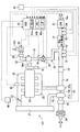
- FIG. 1 is a diagram showing a configuration of a combustion system in the first embodiment.
- FIG. 2 is a diagram showing functional blocks of the ECU
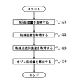
- FIG. 3 is a flowchart showing the processing of the calculation unit
- FIG. 4 is a flowchart showing the processing of the control unit
- FIG. 5 is a graph showing a change in NOx occlusion rate when the ozone supply amount changes
- FIG. 6 is a graph showing the change in the NOx occlusion rate when the CO concentration changes
- FIG. 7 is a graph showing a change in NOx occlusion rate when the catalyst temperature changes
- FIG. 8 is a graph for obtaining a determination line for the ozone supply amount.
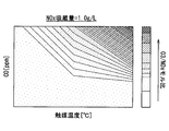
- FIG. 9 is a map for calculating the ozone supply amount.
- FIG. 10 is a diagram showing a configuration of a combustion system in the second embodiment.
- a combustion system 100 shown in FIG. 1 includes an engine 10, a supercharger 11, a NOx purification catalyst 12, and a particulate collection device (hereinafter referred to as DPF) 13.
- Combustion system 100 is mounted on a vehicle, and this vehicle runs using the output of engine 10 as a drive source.
- the engine 10 is a compression self-ignition type diesel engine, and light oil that is a hydrocarbon compound is used as a fuel for combustion.
- An intake passage 15 that supplies air to the engine 10 and an exhaust passage 16 that discharges exhaust from the engine 10 are connected to the engine 10.
- the engine 10 corresponds to an internal combustion engine.
- the supercharger 11 includes an exhaust turbine 11a, a rotating shaft 11b, and a compressor 11c.
- the exhaust turbine 11a is disposed in the exhaust passage 16 of the engine 10 and rotates by the kinetic energy of the exhaust.
- the rotating shaft 11b couples the impellers of the exhaust turbine 11a and the compressor 11c to transmit the rotational force of the exhaust turbine 11a to the compressor 11c.
- the compressor 11 c is disposed in the intake passage 15 and compresses intake air to supercharge the engine 10.
- An intercooler 21 as a cooler for cooling the intake air compressed by the compressor 11c is provided downstream of the compressor 11c in the intake passage 15.
- the intake passage 15 is connected to the intake side of the engine 10 via the intake manifold 22.
- the compressed intake air cooled by the intercooler 21 is adjusted in flow rate by a throttle valve 23 and distributed to a plurality of combustion chambers of the engine 10.
- An air cleaner 24 that purifies the air taken into the engine 10 is provided at the upstream end of the intake passage 15.
- the exhaust passage 16 is connected to the exhaust side of the engine 10 via the exhaust manifold 25.
- the NOx purification catalyst 12 is disposed on the downstream side of the exhaust turbine 11 a in the exhaust passage 16.
- a DPF (Diesel Particulate Filter) 13 is disposed further downstream of the NOx purification catalyst 12 and is a collection device that collects particulate matter PM (Particulate Matter) contained in the exhaust gas.
- Exhaust gas flowing through the exhaust passage 16 passes through both the NOx purification catalyst 12 and the DPF 13 and is then discharged from the exhaust outlet 16a.
- the NOx purification catalyst 12 and the DPF 13 constitute an exhaust purification device.
- PM is solid or liquid fine particles
- solid fine particles are soot, for example, as soot
- liquid fine particles are unburned HC such as liquefied HC, for example.
- the NOx purification catalyst 12 includes a storage catalyst that stores nitrogen oxides (NOx) in the exhaust, a reduction catalyst that reduces NOx to nitrogen, and the like.
- the storage catalyst has a storage power for storing NOx, and in the storage catalyst, the storage power for NO 2 is much larger than the storage power for NO.
- the NOx purification catalyst 12 corresponds to the catalyst.
- the combustion system 100 includes an ozone supply device 30 that supplies ozone to the upstream side of the NOx purification catalyst 12 in the exhaust passage 16.
- ozone is supplied from the ozone supply device 30 to the exhaust passage 16
- NO is oxidized to NO 2 by ozone.
- the ozone supply device 30 can be switched between a supply state in which ozone is supplied to the exhaust passage 16 and a stop state in which ozone is not supplied.
- the ozone supply device 30 includes an ozone passage 31 connected to the exhaust passage 16, an ozone generation section 32 that generates ozone, an air pump 33 that sends air, an exhaust cutoff valve 34 that shuts off the backflow of exhaust, and various sensors.
- an air pump 33 is provided at the upstream end thereof, and an ozone generation unit 32 is provided between the air pump 33 and the exhaust passage 16.
- the ozone passage 31 is formed by connecting a plurality of pipes.
- the air pump 33 sends air to the ozone generator 32 through the ozone passage 31.
- the air pump 33 is a centrifugal air pump 33 and is configured by housing an impeller driven by an electric motor in a case.
- the air pump 33 has a suction port 33a for sucking air, and the suction port 33a is formed in the case.
- a suction port 33 a of the air pump 33 forms the upstream end of the ozone passage 31.
- the ozone generating unit 32 includes a housing that forms a flow path therein, and a plurality of electrodes are disposed in the flow path. These electrodes have a flat plate shape arranged so as to face each other in parallel, and electrodes to which a high voltage is applied and electrodes having a ground voltage are alternately arranged. Air blown by the air pump 33 flows into the housing of the ozone generator 32. This air flows into the flow passage in the housing and flows through the interelectrode passage, which is a passage between the electrodes.
- the electrode of the ozone generator 32 When the electrode of the ozone generator 32 is energized, electrons emitted from the electrode collide with oxygen molecules contained in the air in the interelectrode passage. Then, ozone is generated from oxygen molecules. That is, the ozone generator 32 generates ozone by changing oxygen molecules into a plasma state by discharge. Accordingly, when the ozone generator 32 is energized, ozone is contained in the air flowing from the ozone generator 32 toward the exhaust passage 16. In the ozone generation unit 32, the ozone generation rate increases as the amount of current supplied to the electrode increases.
- the ozone generator 32 can also be called an ozonizer.
- the exhaust shut-off valve 34 is an electromagnetically driven on-off valve, and is provided between the ozone generator 32 and the exhaust passage 16 in the ozone passage 31. In this case, the exhaust cutoff valve 34 is arranged at a position spaced from the downstream end of the ozone passage 31 to the upstream side. The exhaust cutoff valve 34 can be switched between an open state that allows ventilation and a closed state that blocks ventilation.
- the ozone supply device 30 includes a pressure sensor 35 that detects the internal pressure of the ozone passage 31 as a gas pressure as a sensor, and a flow rate sensor 36 that detects the flow rate of air sent from the air pump 33 to the ozone passage 31 as a gas flow rate. ing.
- the pressure sensor 35 is provided between the ozone generator 32 and the exhaust cutoff valve 34 in the ozone passage 31. Specifically, the pressure sensor 35 is disposed at a position near the ozone generator 32. In this case, the pressure change accompanying the opening / closing of the exhaust cutoff valve 34 is easily reflected in the detection result of the pressure sensor 35.
- the flow sensor 36 is provided between the air pump 33 and the ozone generator 32 in the ozone passage 31, and can detect the amount of air discharged from the air pump 33. Specifically, the flow sensor 36 is arranged at a position near the air pump 33. In this case, the detection result of the flow sensor 36 is easily reflected in the change in air flow accompanying the driving and stopping of the air pump 33.
- the combustion system 100 has an electronic control unit (abbreviated as ECU) 40 as a control device.
- the ECU 40 includes a processor 41a, a memory 41b, and an interface (I / F) 41c for inputting and outputting information.
- the memory 41b is a storage unit and is a non-transitional tangible storage medium that stores a computer-readable program and data in a non-temporary manner.
- the memory 41b is realized by a semiconductor memory or a magnetic disk.
- the ECU 40 is connected to an engine rotation sensor 42, an intake pressure sensor 43, an air flow meter 44, an accelerator opening sensor 45, and a throttle opening sensor 46.
- the engine speed is detected by an engine rotation sensor 42 attached in the vicinity of the output shaft 10 a of the engine 10.
- Examples of the physical quantity representing the engine load include intake pressure, intake air amount, accelerator pedal depression amount, and the like.
- the intake pressure is detected by an intake pressure sensor 43 attached to the downstream portion of the compressor 11c in the intake passage 15.
- the intake air amount is detected by an air flow meter 44 attached to the upstream side portion of the compressor 11c in the intake passage 15.
- the accelerator pedal depression amount is detected by an accelerator opening sensor 45 attached to the accelerator pedal.
- the opening of the throttle valve 23 is detected by a throttle opening sensor 46 attached to the throttle valve 23.
- the ECU 40 is connected with an exhaust temperature sensor 51, an exhaust pressure sensor 52, a catalyst temperature sensor 53, a pressure sensor 35, a flow rate sensor 36, and a NOx sensor 54.
- the ECU 40 acquires the physical quantity detected by the sensor in addition to the detected value of the operating state of the engine 10 such as the engine speed and the engine load. Then, the operation of the ozone supply device 30 is controlled based on these physical quantities. Therefore, the ECU 40 functions as an ozone supply control device.
- the exhaust temperature sensor 51 is attached to the exhaust passage 16 and detects the exhaust temperature.
- the exhaust pressure sensor 52 is attached to the exhaust passage 16 and detects the exhaust pressure.
- the exhaust temperature sensor 51 and the exhaust pressure sensor 52 are disposed in the exhaust passage 16 between the NOx purification catalyst 12 and the exhaust turbine 11a.
- the catalyst temperature sensor 53 is provided between the NOx purification catalyst 12 and the DPF 13 in the exhaust passage 16 and detects the internal temperature of the NOx purification catalyst 12 by detecting the temperature of the exhaust gas that has passed through the NOx purification catalyst 12. .
- the catalyst temperature sensor 53 may be attached to the NOx purification catalyst 12.
- the NOx sensor 54 is provided between the NOx purification catalyst 12 and the DPF 13 in the exhaust passage 16 and detects the NOx concentration of the exhaust gas that has passed through the NOx purification catalyst 12.
- the ECU 40 executes the control program stored in the memory 41b by the processor 41a, thereby constructing the control unit 62, the calculation unit 61, the temperature acquisition unit 63, and the concentration acquisition unit 64 shown in FIG. 2 as functional blocks.
- the control unit 62 controls the supply amount of ozone. As shown in FIG. 1, the ozone generator 32, the air pump 33, and the exhaust cutoff valve 34 are connected to the ECU 40 as actuators. The control unit 62 controls the operation of these actuators by outputting a command signal. For the ozone generator 32, the controller 62 adjusts the amount of ozone generated by the ozone generator 32 by controlling voltage application to the electrodes. Moreover, the control part 62 adjusts the ventilation volume by the air pump 33 by controlling the power supply amount to the air pump 33 by duty control about the air pump 33. FIG. As described above, the control unit 62 controls the ozone generation unit 32 and the air pump 33 to control the supply amount of ozone supplied to the exhaust passage 16.
- the temperature acquisition unit 63 uses the detection information acquired from the catalyst temperature sensor 53 to calculate the catalyst temperature.
- the concentration acquisition unit 64 estimates the CO concentration, which is the carbon monoxide concentration in the exhaust, based on the engine operating state.
- the calculation unit 61 calculates the storage amount of NOx stored in the NOx purification catalyst 12.
- the processor 41a repeatedly executes the program of the procedure shown in FIG. 3 at a predetermined cycle.
- S11 the NOx concentration on the upstream side of the NOx purification catalyst 12 is acquired, and the process proceeds to S12.
- estimation according to the operating state of the engine 10 can be cited.
- the NOx concentration with respect to the engine operating state values such as the engine load, the engine speed, the EGR rate, the supercharging pressure, and the like is obtained by testing in advance, and the test result is mapped and stored. Then, based on the actually detected value of the engine operating state, the NOx concentration is calculated with reference to the map.
- the NOx concentration on the downstream side of the NOx purification catalyst 12 is acquired, and the process proceeds to S13.
- the downstream NOx concentration is determined using the detection information acquired by the NOx sensor 54.
- the current storage amount in the NOx purification catalyst 12 is calculated, and the process proceeds to S14.
- the instantaneous storage amount is calculated by using the difference between the upstream NOx concentration in S12 and the downstream NOx concentration in S13.
- the current accumulated storage amount obtained in S13 is added to the previous accumulated storage amount to obtain the latest accumulated storage amount, and this flow is terminated.
- the accumulated occlusion amount is the accumulated NOx occlusion amount.
- the amount of occlusion in the NOx purification catalyst 12 can be currently calculated by the processing of the calculation unit 61 in FIG.
- the information calculated by the calculation unit 61 is stored in the memory 41b.
- the microcomputer repeatedly executes the program of the procedure shown in FIG. 4 at a predetermined cycle.
- the NOx occlusion amount is acquired from the memory 41b, and the process proceeds to S22.
- the NOx occlusion amount read from the memory 41b is the latest accumulated NOx occlusion amount.
- the catalyst temperature is acquired from the catalyst temperature sensor 53, and the process proceeds to S23.
- the CO concentration is acquired, and the process proceeds to S24.
- estimation according to the operating state of the engine 10 can be cited.
- the CO concentration with respect to the values of the engine operating state such as the engine load, the engine speed, the EGR rate, the supercharging pressure, and the like is obtained by testing in advance, and the test result is mapped and stored. Based on the actually detected value of the engine operating state, the CO concentration is calculated with reference to the map.
- the ozone supply amount is calculated using the occlusion amount acquired in S21 as a determination condition, and this flow ends.
- the required ozone supply amount is calculated as a molar ratio with respect to NO in the exhaust based on the NOx occlusion amount, the catalyst temperature, and the CO concentration.
- the ozone supply amount is calculated by a map having three pieces of information as inputs.
- FIG. 5 shows waveforms of three molar ratios.
- the ozone supply amount necessary to obtain a high NOx storage rate increases. Therefore, instead of simply determining the ozone supply amount based on the molar ratio to NOx, it is required to estimate the NOx storage amount of the NOx purification catalyst 12 and to determine the ozone supply amount accordingly.
- the effect of ozone supply actually appears in a state where NOx is occluded in the NOx purification catalyst 12 to some extent, and when the NOx purification catalyst 12 immediately after NOx desorption and reduction is performed is clean.
- the effect of ozone supply is not so great. This is because the clean NOx purification catalyst 12 is easy to occlude even in the NO state. Therefore, a parameter called the NOx occlusion amount to the NOx purification catalyst 12 is added to the calculation of the ozone supply amount, and the ozone supply amount to the exhaust passage 16 is controlled to increase as the occlusion amount increases. This is because even if the NOx purification catalyst 12 has already stored a large amount, the metal stored on the NOx purification catalyst 12 is changed by ozone, or even the same metal is easily stored by ozone.
- the required amount of ozone for a given NOx occlusion amount is not uniquely determined, and the required amount of ozone varies even at the same NOx occlusion amount depending on the catalyst temperature at that time and the CO concentration coexisting in the exhaust gas. Specifically, as shown in FIG. 6, the NOx occlusion rate decreases as the CO concentration increases even at the same molar ratio. As shown in FIG. 7, even if the molar ratio is the same, the NOx occlusion rate decreases as the catalyst temperature increases.
- the control is performed with the minimum ozone supply amount that provides the desired NOx storage performance. In other words, on the condition that the storage rate in the NOx purification catalyst 12 is equal to or greater than a predetermined threshold value, the ozone supply amount is determined to be small.
- FIG. 8 shows the NOx molar ratio and the NOx occlusion rate for each CO concentration when the catalyst temperature is 150 ° C.
- a decision line indicated by a broken line can be determined. For example, when the CO concentration is 200 ppm, the ozone supply amount is determined so that the molar ratio is about 2.5. Information on such decision lines is stored in the memory 41b as a map.
- the ozone supply amount is calculated by a constant map with the NOx storage amount already stored in the NOx purification catalyst 12, the catalyst temperature, and the CO concentration as inputs.
- the NOx storage amount in the NOx purification catalyst 12 is divided into several levels, and a constant map having the catalyst temperature and the CO concentration as axes is created for each level.
- a map in which the NOx occlusion amount is 1.0 g / L is shown, but such a map is stored in the memory 41b for each of a plurality of NOx occlusion amounts.
- the ozone supply amount is obtained as the NO molar ratio by interpolation between the NOx occlusion amount levels.
- the constant value is set so that the lower limit ozone supply amount is within a range in which the NOx occlusion performance can be reliably obtained.
- the amount of ozone supplied to the exhaust passage 16 is controlled using the amount of NOx stored in the NOx purification catalyst 12.
- the required supply amount of ozone varies depending on the storage amount of NOx stored in the catalyst. Accordingly, the NOx storage amount is calculated by the calculation unit 61, and the amount of supply is determined using the storage amount as a determination condition. Therefore, excess or deficiency of ozone supply can be reduced. As a result, it is possible to suppress the generation of ozone and waste of ozone. Moreover, it is possible to suppress a decrease in the purification capacity due to insufficient ozone generation and insufficient ozone. Therefore, since it can suppress that ozone is generated too much, waste of energy consumed for ozone generation can be suppressed.
- the supply amount to the exhaust passage 16 is controlled to increase as the storage amount calculated by the calculation unit 61 increases. If the amount of occlusion is small, NOx can be occluded by the NOx purification catalyst 12 even if the amount of ozone supplied is small. However, if the amount of occlusion increases, the occlusion rate decreases unless NOx is oxidized by ozone. is there. Thereby, the occlusion rate can be improved.
- the NOx purification catalyst 12 suppresses excessive power consumption and heat generation in a clean state with a small amount of occlusion, and even if occlusion progresses and the occlusion performance of the NOx purification catalyst 12 decreases, more reliable NOx occlusion is achieved. Can be realized.
- the supply amount to the exhaust passage 16 is controlled using the storage amount and the catalyst temperature.
- the catalyst temperature is a factor that affects the storage rate in the NOx purification catalyst 12, as shown in FIG. Since the ozone supply amount is determined in consideration of such factors, NOx can be oxidized and occluded more reliably.
- the supply amount to the exhaust passage 16 is controlled using the occlusion amount and the CO concentration.
- the CO concentration is a factor that affects the storage rate in the NOx purification catalyst 12 as shown in FIG.
- the ozone supply amount is determined in consideration of such factors, so that NOx can be oxidized and stored more reliably.
- the supply amount is determined to be small on condition that the storage rate in the catalyst is equal to or greater than a predetermined threshold.
- the ozone supply amount is determined aiming at the lower limit of the range in which the NOx occlusion rate of a certain level or more is obtained. Thereby, ozone can be supplied too much to prevent ozone from being released into the atmosphere.
- a map showing the relationship of the supply amount to the storage amount, the catalyst temperature, and the CO concentration is stored in the memory 41b.
- the control part 62 determines supply_amount
- the calculation unit 61 calculates the occlusion amount using the NOx concentration acquired upstream of the NOx purification catalyst 12 and the NOx concentration acquired downstream of the NOx purification catalyst 12. As a result, the estimation accuracy can be improved as compared with the case where the storage amount is calculated using the NOx concentration acquired only on either the upstream side or the downstream side of the NOx purification catalyst 12. Therefore, the supply amount of ozone can be controlled with high accuracy.
- an oxidation catalyst 71 is disposed upstream of the NOx purification catalyst 12 in the exhaust passage 16.
- the oxidation catalyst 71 has a function of oxidizing CO. Therefore, CO in the exhaust gas is oxidized to carbon dioxide (CO 2 ) when passing through the oxidation catalyst 71. Since CO 2 has little influence on the storage rate of the NOx purification catalyst 12, it is not necessary to consider the amount of CO 2 . Further, since CO is oxidized, there is no need to consider the CO concentration. Thereby, the calculation load for determining the ozone supply amount by the control unit 62 can be reduced.
- the NOx concentration on the upstream side of the NOx purification catalyst 12 is estimated according to the operating state of the engine 10, but is not limited to such an estimation method.
- a NOx sensor 54 may be mounted upstream of the catalyst to directly detect the NOx concentration.
- the ozone supply control device is strengthened for the compression self-ignition type diesel engine.
- it is an internal combustion engine, it may be a gasoline engine instead of a diesel engine.
- the ozone supply amount is determined using the map, but the present invention is not limited to the calculation method using the map.
- the ozone supply amount may be determined by calculating from time to time using a predetermined function or the like.
- the ozone supply amount is determined using the catalyst temperature, but the ozone supply amount may be determined without using the catalyst temperature. Further, the ozone supply amount may be determined using other parameters related to the catalyst temperature and the CO concentration.
- the ozone supply control device is realized by the ECU 40, but is not limited to such a configuration.
- Means and / or functions provided by the ECU 40 as the ozone supply control device may be provided by software recorded in a substantial storage medium and a computer that executes the software, software only, hardware only, or a combination thereof. it can.
- the controller is provided by a circuit that is hardware, it can be provided by a digital circuit including a number of logic circuits, or an analog circuit.
- it replaces with ECU40 and a microcomputer may provide an ozone supply control apparatus, and the processor 41a which a microcomputer has may provide an ozone supply control apparatus.
- the exhaust gas discharged from the in-vehicle internal combustion engine is purified.
- the exhaust gas is not limited to the in-vehicle internal combustion engine, and may be an internal combustion engine mounted on a ship, a railway vehicle, an aircraft, or the like.
- the present invention can also be applied to an exhaust purification system that purifies the exhaust of a fuel engine.
- the present invention is also applicable to an exhaust purification system that purifies exhaust from internal combustion engines and external combustion engines installed for power generation.
Landscapes
- Engineering & Computer Science (AREA)
- Chemical & Material Sciences (AREA)
- Combustion & Propulsion (AREA)
- General Engineering & Computer Science (AREA)
- Mechanical Engineering (AREA)
- Chemical Kinetics & Catalysis (AREA)
- Health & Medical Sciences (AREA)
- General Chemical & Material Sciences (AREA)
- Oil, Petroleum & Natural Gas (AREA)
- Analytical Chemistry (AREA)
- Environmental & Geological Engineering (AREA)
- Biomedical Technology (AREA)
- Exhaust Gas After Treatment (AREA)
- Exhaust Gas Treatment By Means Of Catalyst (AREA)
Abstract
オゾン供給制御装置は、内燃機関(10)の排気中のNOxを吸蔵して還元する触媒(12)が配置されている排気通路(16)のうち、触媒の上流側へオゾンを供給するオゾン供給装置(30)の作動を制御する。オゾン供給制御装置は、触媒に吸蔵されているNOxの吸蔵量を算出する算出部(61)と、算出部によって算出された吸蔵量を用いて、オゾンの排気通路への供給量を制御する制御部(62)と、を含む。
Description
本出願は、2016年5月31日に出願された日本特許出願番号2016-108555号に基づくもので、ここにその記載内容を援用する。
本開示は、排気の浄化に用いられるオゾンの供給を制御するオゾン供給制御装置に関する。
従来、エンジンの排気が通過する排気通路に対してオゾンを供給するオゾン供給装置が知られている。排気通路に窒素酸化物(NOx)を吸蔵するNOx浄化触媒が設けられた構成では、排気通路にオゾンを供給して、一酸化窒素(NO)がオゾン(03)により二酸化窒素(NO2)に酸化される。これによってNOx浄化触媒での吸蔵反応が活発になり、NOxの浄化率が高められる。
オゾンを排気通路に供給する量は、排気の状態によって制御される。特許文献1には、排気中のNOの濃度であるNO濃度に対するモル比率が1以上または2以上となるようにオゾンを供給している。これによってNOのNO2化、さらにはNO3化を促進し、NOx吸蔵反応を高めている。
前述の特許文献1に記載の技術では、NO濃度に対するモル比率が高いほどNO3化が促進されるので、より高い吸蔵効果が得られる。しかしながら、実際にはNOx浄化触媒におけるNOxの吸蔵は、すでにNOx浄化触媒に吸蔵されているNOx吸蔵量によっても影響を受ける。したがってNO濃度のみを考慮してオゾン供給量を決定しても、想定した効果が得られないおそれがある。またNO濃度のみを考慮してオゾン供給量を決定しても、オゾン供給量が多すぎる場合には、オゾンを生成するためのエネルギが無駄になるおそれがある。
本開示は、オゾンの供給の過不足を少なくして、オゾンを生成するためのエネルギの無駄を抑制することができるオゾン供給制御装置を提供することを目的とする。
本開示の一態様によるオゾン供給制御装置は、内燃機関の排気中のNOxを吸蔵して還元する触媒が配置されている排気通路のうち、触媒の上流側へオゾンを供給するオゾン供給装置の作動を制御する。オゾン供給制御装置は、触媒に吸蔵されているNOxの吸蔵量を算出する算出部と、算出部によって算出された吸蔵量を用いて、オゾンの排気通路への供給量を制御する制御部と、を含む。
このような本開示に従えば、吸蔵量を用いてオゾンの排気通路への供給量を制御している。必要なオゾンの供給量は、触媒に吸蔵されているNOxの吸蔵量によって変化する。そこで算出部でNOxの吸蔵量を算出し、吸蔵量を用いて供給量の多寡を判断している。したがってオゾンの供給の過不足を少なくすることができる。これによってオゾンを生成しすぎて、オゾンが無駄になることを抑制することができる。またオゾンの生成が少なすぎて、オゾンが不足して浄化能力が低下することを抑制することができる。したがってオゾンを生成しすぎる過多状態を防ぐことができるため、オゾン生成に消費するエネルギの無駄を抑制することができる。
本開示についての上記目的およびその他の目的、特徴や利点は、添付の図面を参照しながら下記の詳細な記述により、より明確になる。その図面は、
図1は、第1実施形態における燃焼システムの構成を示す図であり、
図2は、ECUの機能ブロックを示す図であり、
図3は、算出部の処理を示すフローチャートであり、
図4は、制御部の処理を示すフローチャートであり、
図5は、オゾン供給量が変化した場合のNOx吸蔵率の変化を示すグラフであり、
図6は、CO濃度が変化した場合のNOx吸蔵率の変化を示すグラフであり、
図7は、触媒温度が変化した場合のNOx吸蔵率の変化を示すグラフであり、
図8は、オゾン供給量の決定ラインを求めるためのグラフであり、
図9は、オゾン供給量を算出するためのマップであり、
図10は、第2実施形態における燃焼システムの構成を示す図である。
以下、図面を参照しながら本開示を実施するための形態を、複数の形態を用いて説明する。各実施形態で先行する実施形態で説明している事項に対応している部分には同一の参照符を付すか、または先行の参照符号に一文字追加し、重複する説明を略する場合がある。また各実施形態にて構成の一部を説明している場合、構成の他の部分は、先行して説明している実施形態と同様とする。各実施形態で具体的に説明している部分の組合せばかりではなく、特に組合せに支障が生じなければ、実施形態同士を部分的に組合せることも可能である。
(第1実施形態)
本開示の第1実施形態に関して、図1~図9を用いて説明する。図1に示す燃焼システム100は、エンジン10、過給機11、NOx浄化触媒12および微粒子捕集装置(以下、DPF)13を備えている。燃焼システム100は車両に搭載されたものであり、この車両は、エンジン10の出力を駆動源として走行する。エンジン10は、圧縮自着火式のディーゼルエンジンであり、燃焼に用いる燃料には、炭化水素化合物である軽油を用いている。エンジン10には、このエンジン10に空気を供給する吸気通路15と、エンジン10からの排気を放出する排気通路16とが接続されている。エンジン10は、内燃機関に相当する。
本開示の第1実施形態に関して、図1~図9を用いて説明する。図1に示す燃焼システム100は、エンジン10、過給機11、NOx浄化触媒12および微粒子捕集装置(以下、DPF)13を備えている。燃焼システム100は車両に搭載されたものであり、この車両は、エンジン10の出力を駆動源として走行する。エンジン10は、圧縮自着火式のディーゼルエンジンであり、燃焼に用いる燃料には、炭化水素化合物である軽油を用いている。エンジン10には、このエンジン10に空気を供給する吸気通路15と、エンジン10からの排気を放出する排気通路16とが接続されている。エンジン10は、内燃機関に相当する。
過給機11は、排気タービン11a、回転軸11bおよびコンプレッサ11cを備える。排気タービン11aは、エンジン10の排気通路16に配置され、排気の運動エネルギにより回転する。回転軸11bは、排気タービン11aおよびコンプレッサ11cの各インペラを結合することで、排気タービン11aの回転力をコンプレッサ11cに伝達する。コンプレッサ11cは、吸気通路15に配置されており、吸気を圧縮してエンジン10に過給する。
吸気通路15においてコンプレッサ11cの下流側には、このコンプレッサ11cで圧縮された吸気を冷却する冷却器としてのインタークーラ21が設けられている。吸気通路15は、吸気マニホールド22を介してエンジン10の吸気側に接続されている。インタークーラ21により冷却された圧縮吸気は、スロットルバルブ23により流量調整され、エンジン10が有する複数の燃焼室へ分配される。吸気通路15の上流端には、エンジン10に吸入される空気の浄化を行うエアクリーナ24が設けられている。
排気通路16は、排気マニホールド25を介してエンジン10の排気側に接続されている。NOx浄化触媒12は、排気通路16において排気タービン11aの下流側に配置されている。DPF(Diesel Particulate Filter)13は、NOx浄化触媒12の更に下流側に配置されており、排気に含まれている粒子状物質PM(Particulate Matter)を捕集する捕集装置である。排気通路16を流れる排気は、NOx浄化触媒12およびDPF13の両方を通過した後に、排気出口16aから放出される。燃焼システム100においては、NOx浄化触媒12およびDPF13が排気浄化装置を構成している。なお、PMは個体や液体の微粒子であり、固体の微粒子は、例えば煤としてのsootであり、液体の微粒子は、例えば液化HCなどの未燃HCである。
NOx浄化触媒12は、排気中の窒素酸化物(NOx)を吸蔵する吸蔵触媒や、NOxを窒素に還元する還元触媒などを有している。吸蔵触媒は、NOxを吸蔵する吸蔵力を有しており、吸蔵触媒においては、NOに対する吸蔵力に比べてNO2に対する吸蔵力の方が非常に大きくなっている。NOx浄化触媒12が触媒に相当する。
燃焼システム100は、排気通路16においてNOx浄化触媒12の上流側にオゾンを供給するオゾン供給装置30を有している。オゾン供給装置30から排気通路16にオゾンが供給された場合、オゾンによりNOがNO2に酸化される。これによって排気中のNO2の割合が増加し、その結果、NOx浄化触媒12でのNOxの吸蔵率が向上する。オゾン供給装置30は、排気通路16にオゾンを供給する供給状態と、オゾンを供給しない停止状態とに切替可能になっている。
オゾン供給装置30は、排気通路16に接続されたオゾン通路31と、オゾンを生成するオゾン生成部32と、空気を送るエアポンプ33と、排気の逆流を遮断する排気遮断弁34と、各種センサを有している。オゾン通路31においては、その上流端にエアポンプ33が設けられており、エアポンプ33と排気通路16との間にオゾン生成部32が設けられている。オゾン通路31は、複数の配管が接続されることなどにより形成されている。
エアポンプ33は、オゾン通路31を通じてオゾン生成部32に空気を送る。エアポンプ33は、遠心式のエアポンプ33であり、電動モータにより駆動されるインペラをケース内に収容して構成される。エアポンプ33は、大気を吸入する吸入口33aを有しており、この吸入口33aはケースに形成されている。エアポンプ33の吸入口33aがオゾン通路31の上流端を形成している。
オゾン生成部32は、その内部に流通路を形成するハウジングを備え、流通路には複数の電極が配置されている。これらの電極は、互いに平行に対向するように配置された平板形状であり、高電圧が印加される電極と接地電圧の電極とが交互に配置されている。オゾン生成部32のハウジングには、エアポンプ33により送風された空気が流入する。この空気は、ハウジング内の流通路に流入し、電極間の通路である電極間通路を流通する。
オゾン生成部32の電極が通電されると、電極から放出された電子が、電極間通路の空気中に含まれる酸素分子に衝突する。すると、酸素分子からオゾンが生成される。つまり、オゾン生成部32は、放電により酸素分子をプラズマ状態にしてオゾンを生成する。したがって、オゾン生成部32への通電時には、オゾン生成部32から排気通路16に向けて流れる空気にオゾンが含まれる。オゾン生成部32においては、電極への通電量が大きいほどオゾンの発生率が大きくなる。オゾン生成部32はオゾナイザと称することもできる。
排気遮断弁34は、電磁駆動式の開閉弁であり、オゾン通路31においてオゾン生成部32と排気通路16との間に設けられている。この場合、排気遮断弁34は、オゾン通路31の下流端から上流側に離間した位置に配置されている。排気遮断弁34は、通気を可能にする開状態と、通気を遮断する閉状態とを切替可能になっている。
オゾン供給装置30は、センサとしてオゾン通路31の内部圧力をガス圧力として検出する圧力センサ35と、エアポンプ33からオゾン通路31に送られる空気の流量をガス流量として検出する流量センサ36とを有している。圧力センサ35は、オゾン通路31においてオゾン生成部32と排気遮断弁34との間に設けられている。具体的には、圧力センサ35は、オゾン生成部32寄りの位置に配置されている。この場合、圧力センサ35の検出結果に、排気遮断弁34の開閉に伴う圧力変化が反映されやすくなっている。
流量センサ36は、オゾン通路31においてエアポンプ33とオゾン生成部32との間に設けられており、エアポンプ33からの空気の吐出量を検出可能になっている。具体的には、流量センサ36は、エアポンプ33寄りの位置に配置されている。この場合、流量センサ36の検出結果に、エアポンプ33の駆動および停止に伴う空気の流量変化が反映されやすくなっている。
次に、燃焼システム100の電気的な構成について説明する。図1に示すように、燃焼システム100は、制御装置としての電子制御装置(Electronic Control Unit:略称ECU)40を有している。ECU40は、プロセッサ41a、メモリ41bおよび情報の入出力を行うインターフェース(I/F)41cを有している。メモリ41bは、記憶部であって、コンピュータによって読み取り可能なプログラムおよびデータを非一時的に格納する非遷移的実体的記憶媒体である。メモリ41bは、半導体メモリまたは磁気ディスクなどによって実現される。
ECU40には、エンジン回転センサ42、吸気圧センサ43、エアフロメータ44、アクセル開度センサ45およびスロットル開度センサ46が接続されている。エンジン回転数は、エンジン10の出力軸10aの近傍に取り付けられたエンジン回転センサ42により検出される。エンジン負荷を表す物理量としては、吸気圧、吸気量、アクセルペダル踏込量等が挙げられる。吸気圧は、吸気通路15のうちコンプレッサ11cの下流側部分に取り付けられた吸気圧センサ43により検出される。吸気量は、吸気通路15のうちコンプレッサ11cの上流側部分に取り付けられたエアフロメータ44により検出される。アクセルペダル踏込量は、アクセルペダルに取り付けられたアクセル開度センサ45により検出される。スロットルバルブ23の開度は、スロットルバルブ23に取り付けられたスロットル開度センサ46により検出される。
また、ECU40には、排気温度センサ51、排気圧センサ52、触媒温度センサ53、圧力センサ35、流量センサ36およびNOxセンサ54が接続されている。ECU40は、エンジン回転数やエンジン負荷等のエンジン10の作動状態の検出値に加え、センサにより検出された物理量を取得する。そして、これらの物理量に基づき、オゾン供給装置30の作動を制御する。したがってECU40は、オゾン供給制御装置として機能する。
排気温度センサ51は、排気通路16に取り付けられて排気温度を検出する。排気圧センサ52は、排気通路16に取り付けられて排気圧力を検出する。排気温度センサ51および排気圧センサ52は、排気通路16においてNOx浄化触媒12と排気タービン11aとの間に配置されている。
触媒温度センサ53は、排気通路16においてNOx浄化触媒12とDPF13との間に設けられており、NOx浄化触媒12を通過した排気の温度を検出することでNOx浄化触媒12の内部温度を検出する。触媒温度センサ53は、NOx浄化触媒12に取り付けられていてもよい。NOxセンサ54は、触媒温度センサ53と同様に、排気通路16においてNOx浄化触媒12とDPF13との間に設けられており、NOx浄化触媒12を通過した排気のNOx濃度を検出する。
ECU40は、メモリ41bに記憶された制御プログラムをプロセッサ41aにより実行することで、図2に示す制御部62、算出部61、温度取得部63および濃度取得部64を機能ブロックとして構築する。
制御部62は、オゾンの供給量を制御する。ECU40には、図1に示すように、オゾン生成部32、エアポンプ33および排気遮断弁34がアクチュエータとして接続されている。制御部62は、指令信号を出力することでこれらアクチュエータの動作制御を行う。制御部62は、オゾン生成部32については、電極への電圧印加を制御することでオゾン生成部32によるオゾンの生成量を調整する。また制御部62は、エアポンプ33については、デューティ制御によりエアポンプ33への供給電力量を制御することでエアポンプ33による送風量を調整する。このように制御部62は、オゾン生成部32およびエアポンプ33を制御して、オゾンを排気通路16に供給する供給量を制御する。
温度取得部63は、触媒温度センサ53から取得した検出情報を用いて、触媒温度を算出する。濃度取得部64は、エンジン運転状態に基づいて排気中の一酸化炭素濃度であるCO濃度を推定する。算出部61は、NOx浄化触媒12に吸蔵されているNOxの吸蔵量を算出する。
次に、算出部61の処理の詳細について、図3を用いて説明する。ECU40は、図3に示す手順のプログラムをプロセッサ41aが所定周期で繰り返し実行する。S11では、NOx浄化触媒12の上流側のNOx濃度を取得し、S12に移る。上流側のNOx濃度の取得方法の一例としては、エンジン10の運転状態に応じた推定が挙げられる。例えば、エンジン負荷、エンジン回転数、EGR率、過給圧等のエンジン運転状態の値に対するNOx濃度を、予め試験して取得しておき、その試験結果をマップ化して記憶させておく。そして、実際に検出されたエンジン運転状態の値に基づき、上記マップを参照してNOx濃度を算出する。
S12では、NOx浄化触媒12の下流側のNOx濃度を取得し、S13に移る。下流側のNOx濃度は、NOxセンサ54によって取得された検出情報を用いて決定する。
S13では、NOx浄化触媒12における今回の吸蔵量を算出し、S14に移る。今回の瞬時の吸蔵量は、S12における上流側のNOx濃度と、S13の下流側のNOx濃度との差分を用いて、NOx吸蔵量が算出される。
S14では、前回の積算吸蔵量に対してS13で求めた今回の瞬時の吸蔵量を加算し、最新の積算吸蔵量を求め、本フローを終了する。この場合、積算吸蔵量は、積算したNOx吸蔵量である。このような図3の算出部61の処理によって、現在、NOx浄化触媒12における吸蔵量を算出することができる。算出部61が算出した情報は、メモリ41bに記憶されている。
次に、制御部62の処理の詳細について、図4を用いて説明する。ECU40は、図4に示す手順のプログラムをマイクロコンピュータが所定周期で繰り返し実行する。S21では、NOx吸蔵量をメモリ41bから取得し、S22に移る。メモリ41bから読み出すNOx吸蔵量は、最新の積算したNOx吸蔵量である。
S22では、触媒温度センサ53から触媒温度を取得し、S23に移る。S23では、CO濃度を取得し、S24に移る。CO濃度の取得方法の一例としては、エンジン10の運転状態に応じた推定が挙げられる。例えば、エンジン負荷、エンジン回転数、EGR率、過給圧等のエンジン運転状態の値に対するCO濃度を、予め試験して取得しておき、その試験結果をマップ化して記憶させておく。そして実際に検出されたエンジン運転状態の値に基づき、上記マップを参照してCO濃度を算出する。
S24では、S21で取得した吸蔵量を判断条件として、オゾン供給量を算出し、本フローを終了する。S24では、具体的には、NOx吸蔵量、触媒温度およびCO濃度の値に基づき、必要となるオゾン供給量を、排気中のNOに対するモル比率として算出する。オゾン供給量は、たとえば3つの情報を入力に持つマップによって算出される。
次に、図4のS24におけるオゾン供給量の算出に関して説明する。図5では、三つのモル比の波形を示している。図5に示すように、NOx浄化触媒12におけるNOx吸蔵量が増えるに従い、高いNOx吸蔵率を得るのに必要なオゾン供給量が大きくなる。したがって単にNOxに対するモル比でオゾン供給量を決めるのではなく、NOx浄化触媒12のNOx吸蔵量を推定し、それに応じてオゾン供給量を決定することが求められる。
換言すると、実際にオゾン供給による効果が大きく現れるのは、ある程度NOx浄化触媒12にNOxが吸蔵した状態であり、NOxの脱離や還元が実施された直後のNOx浄化触媒12がクリーンな状態では、オゾン供給の効果はそれほど大きくない。クリーンなNOx浄化触媒12であると、NOの状態でも吸蔵しやすいからである。そこで、オゾン供給量の算出にNOx浄化触媒12へのNOx吸蔵量というパラメータを加え、吸蔵量が多くなるにつれて、排気通路16へのオゾン供給量を多くなるように制御する。これによって既に多く吸蔵量しているNOx浄化触媒12であっても、オゾンによってNOx浄化触媒12上で吸蔵する金属がかわったり、同じ金属でもオゾンによって吸蔵しやすくなるからである。
あるNOx吸蔵量において、オゾンの必要量が一意に決まるわけではなく、その際の触媒温度や、排気ガス中に共存するCO濃度によって、同じNOx吸蔵量においてもオゾンの必要量が変化する。具体的には、図6に示すように、同じモル比であっても、CO濃度が多くなるにつれて、NOx吸蔵率が低くなる。また図7に示すように、同じモル比であっても、触媒温度が高くなるにつれて、NOx吸蔵率が低くなる。
またモル比を高くすると、NOx吸蔵率の低下は小さくなる傾向になる。これらを考慮すると、より多くのオゾンを供給すれば、NOx吸蔵量などの影響を受けずに、高い吸蔵性能が得られることになるが、オゾンを多量に供給すると、余ったオゾンが大気に放出されるおそれがある。そこで条件に応じて、所望のNOx吸蔵性能が得られる最低限のオゾン供給量で制御する。換言すると、NOx浄化触媒12における吸蔵率が所定の閾値以上であることを条件として、オゾン供給量が少なくなるように決定する。
図8では、触媒温度が150℃のときの、NOxモル比とCO濃度毎のNOx吸蔵率を示している。NOx吸蔵率が0.8を超えて、オゾンの大気放出の回避を考慮すると、破線で示す決定ラインを決定することができる。たとえばCO濃度が200ppmの場合には、モル比が約2.5となるように、オゾン供給量が決定される。このような決定ラインの情報がマップとして、メモリ41bに記憶されている。
換言すると、オゾン供給量は、NOx浄化触媒12に既に吸蔵されているNOx吸蔵量と、触媒温度と、CO濃度を入力とする定数マップによって算出する。具体的には、NOx浄化触媒12におけるNOx吸蔵量をいくつかの水準で分け、その水準ごとに、触媒温度およびCO濃度を軸に持つ定数マップを作成する。図9では、一例として、NOx吸蔵量が1.0g/Lにおけるマップを示しているが、このようなマップが複数のNOx吸蔵量毎にメモリ41bに記憶されている。最終的にはNOx吸蔵量水準間での補間によってオゾン供給量をNOモル比率として求める。また、定数値としては、確実にNOx吸蔵性能を得られる範囲の中で、下限のオゾン供給量となるように設定する。
以上説明したように本実施形態では、NOx浄化触媒12におけるNOxの吸蔵量を用いてオゾンの排気通路16への供給量を制御している。必要なオゾンの供給量は、触媒に吸蔵されているNOxの吸蔵量によって変化する。そこで算出部61でNOxの吸蔵量を算出し、吸蔵量を判断条件として、供給量の多寡を判断している。したがってオゾンの供給の過不足を少なくすることができる。これによってオゾンを生成しすぎて、オゾンが無駄になることを抑制することができる。またオゾンの生成が少なすぎて、オゾンが不足して浄化能力が低下することを抑制することができる。したがってオゾンを生成しすぎることを抑制できるので、オゾン生成に消費するエネルギの無駄を抑制することができる。
また本実施形態では、算出部61によって算出された吸蔵量が多くなるにつれて、排気通路16への供給量を多くなるように制御する。吸蔵量が少ない場合には、オゾン供給量が少なくても、NOxをNOx浄化触媒12にて吸蔵することができるが、吸蔵量が多くなるとオゾンによってNOxを酸化しないと吸蔵率が低下するからである。これによって吸蔵率を向上することができる。したがってNOx浄化触媒12が吸蔵量が少ないクリーンな状態での余分な電力消費および発熱を抑制しつつ、かつ吸蔵が進みNOx浄化触媒12の吸蔵性能が低下しても、より確実なNOxの吸蔵を実現することができる。
さらに本実施形態では、吸蔵量および触媒温度を用いて、排気通路16への供給量を制御する。触媒温度は、図6で示したようにNOx浄化触媒12における吸蔵率に影響を与える因子である。このような因子を考慮しつつ、オゾン供給量を決定するので、NOxを酸化して、よりの確実に吸蔵することができる。
また本実施形態では、吸蔵量およびCO濃度を用いて、排気通路16への供給量を制御する。CO濃度は、図7で示したようにNOx浄化触媒12における吸蔵率に影響を与える因子である。触媒温度と同様に、このような因子を考慮しつつ、オゾン供給量を決定するので、NOxを酸化して、よりの確実に吸蔵することができる。
また本実施形態では、触媒における吸蔵率が所定の閾値以上であることを条件として、供給量が少なくなるように決定している。換言すると、NOx吸蔵量に応じたオゾン供給において、ある一定以上のNOx吸蔵率が得られる範囲の下限を狙ってオゾン供給量を決定する。これによってオゾンを供給しすぎて、オゾンの大気放出を防ぐことができる。
また本実施形態では、吸蔵量、触媒温度およびCO濃度とに対する供給量の関係を示したマップがメモリ41bに記憶されている。そして制御部62は、マップを用いて供給量を決定してる。これによって供給量を決定するさいの、ECU40の演算負荷を低減することができる。
また本実施形態では、NOx浄化触媒12の上流で取得したNOx濃度とNOx浄化触媒12の下流で取得したNOx濃度とを用いて算出部61は吸蔵量を算出している。これによってNOx浄化触媒12の上流側または下流側のいずれか一方のみで取得したNOx濃度を用いて吸蔵量を算出する場合に比べて、推定精度を向上することができる。したがってオゾンの供給量を高精度に制御することができる。
(第2実施形態)
次に、本開示の第2実施形態の燃焼システム101に関して、図10を用いて説明する。本実施形態では、排気通路16において、NOx浄化触媒12の上流側に酸化触媒71が配置されている。
次に、本開示の第2実施形態の燃焼システム101に関して、図10を用いて説明する。本実施形態では、排気通路16において、NOx浄化触媒12の上流側に酸化触媒71が配置されている。
酸化触媒71は、COを酸化する機能を持つ。したがって排気中のCOは、酸化触媒71を通過する際に酸化されて二酸化炭素(CO2)となる。CO2は、NOx浄化触媒12の吸蔵率に与える影響が少ないので、CO2の量を考慮する必要がない。またCOが酸化されるので、CO濃度を考慮する必要がない。これによって制御部62によるオゾン供給量の決定の演算負荷を軽減することができる。
(その他の実施形態)
以上、本開示の好ましい実施形態について説明したが、本開示は前述した実施形態に何ら制限されることなく、本開示の主旨を逸脱しない範囲において種々変形して実施することが可能である。
以上、本開示の好ましい実施形態について説明したが、本開示は前述した実施形態に何ら制限されることなく、本開示の主旨を逸脱しない範囲において種々変形して実施することが可能である。
前述の実施形態の構造は、あくまで例示であって、本開示の範囲はこれらの記載の範囲に限定されるものではない。本開示の範囲は、請求の範囲の記載によって示され、さらに請求の範囲の記載と均等の意味及び範囲内での全ての変更を含むものである。
また前述の第1実施形態では、NOx浄化触媒12の上流側のNOx濃度は、エンジン10の運転状態に応じて推定しているが、このような推定方法に限るものではない。たとえば触媒の上流にもNOxセンサ54を搭載し、NOx濃度を直接検出してもよい。
前述の第1実施形態では、圧縮自着火式のディーゼルエンジンにオゾン供給制御装置を手強しているが、内燃機関であれば、ディーゼルエンジンではなく、ガソリンエンジンであってもよい。
前述の第1実施形態では、マップを用いてオゾン供給量を決定してるが、マップを用いる演算方法に限るものではない。所定の関数などを用いて、随時算出して、オゾン供給量を決定してもよい。
前述の第1実施形態では、触媒温度を用いてオゾン供給量を決定しているが、触媒温度を用いずに、オゾン供給量を決定してもよい。また触媒温度およびCO濃度に関連する他のパラメータを用いて、オゾン供給量を決定してもよい。
前述の第1実施形態は、ECU40によってオゾン供給制御装置を実現しているが、このような構成に限るものではない。オゾン供給制御装置としてのECU40が提供する手段および/または機能は、実体的な記憶媒体に記録されたソフトウェアおよびそれを実行するコンピュータ、ソフトウェアのみ、ハードウェアのみ、あるいはそれらの組合せによって提供することができる。例えば、制御装置がハードウェアである回路によって提供される場合、それは多数の論理回路を含むデジタル回路、またはアナログ回路によって提供することができる。また、ECU40に替えてマイクロコンピュータがオゾン供給制御装置を提供してもよいし、マイクロコンピュータが有するプロセッサ41aがオゾン供給制御装置を提供してもよい。
前述の第1実施形態では、車載の内燃機関から排出される排気を浄化する構成であったが、車載の内燃機関に限らず、船舶、鉄道車両、および航空機等に搭載された内燃機関または外燃機関の排気を浄化する排気浄化システムにも適用可能である。さらに、発電用に設置された内燃機関および外燃機関の排気を浄化する排気浄化システムにも適用可能である。
本開示は、実施例に準拠して記述されたが、本開示は当該実施例や構造に限定されるものではないと理解される。本開示は、様々な変形例や均等範囲内の変形をも包含する。加えて、様々な組み合わせや形態、さらには、それらに一要素のみ、それ以上、あるいはそれ以下、を含む他の組み合わせや形態をも、本開示の範疇や思想範囲に入るものである。
Claims (7)
- 内燃機関(10)の排気中のNOxを吸蔵して還元する触媒(12)が配置されている排気通路(16)のうち、前記触媒の上流側へオゾンを供給するオゾン供給装置(30)の作動を制御するオゾン供給制御装置であって、
前記触媒に吸蔵されているNOxの吸蔵量を算出する算出部(61)と、
前記算出部によって算出された吸蔵量を用いて、前記オゾンの前記排気通路への供給量を制御する制御部(62)と、を含むオゾン供給制御装置。 - 前記制御部は、前記算出部によって算出された吸蔵量が多くなるにつれて、前記排気通路への前記供給量が多くなるように制御する請求項1に記載のオゾン供給制御装置。
- 前記触媒の温度である触媒温度を取得する温度取得部(63)をさらに含み、
前記制御部は、前記吸蔵量および前記触媒温度を用いて、前記排気通路への前記供給量を制御する請求項1または2に記載のオゾン供給制御装置。 - 前記排気中の一酸化炭素の濃度を取得する濃度取得部(64)をさらに含み、
前記制御部は、前記吸蔵量および前記濃度を用いて、前記排気通路への前記供給量を制御する請求項1~3のいずれか1つに記載のオゾン供給制御装置。 - 前記触媒の温度である触媒温度を取得する温度取得部(63)と、
前記排気中の一酸化炭素の濃度を取得する濃度取得部(64)と、
前記吸蔵量、前記触媒温度および前記濃度とに対する前記供給量の関係を示したマップが記憶されている記憶部(41b)と、をさらに含み、
前記制御部は、前記マップを用いて、前記供給量を決定する請求項1に記載のオゾン供給制御装置。 - 前記制御部は、前記触媒における吸蔵率が所定の閾値以上であることを条件として、前記供給量が少なくなるように決定する請求項1~5のいずれか1つに記載のオゾン供給制御装置。
- 前記算出部は、前記触媒の上流で取得したNOx濃度と前記触媒の下流で取得したNOx濃度とを用いて前記吸蔵量を算出する請求項1~6のいずれか1つに記載のオゾン供給制御装置。
Priority Applications (1)
| Application Number | Priority Date | Filing Date | Title |
|---|---|---|---|
| DE112017002702.0T DE112017002702T5 (de) | 2016-05-31 | 2017-04-12 | Ozonzufuhrsteuervorrichtung |
Applications Claiming Priority (2)
| Application Number | Priority Date | Filing Date | Title |
|---|---|---|---|
| JP2016108555A JP6569601B2 (ja) | 2016-05-31 | 2016-05-31 | オゾン供給制御装置 |
| JP2016-108555 | 2016-05-31 |
Publications (1)
| Publication Number | Publication Date |
|---|---|
| WO2017208636A1 true WO2017208636A1 (ja) | 2017-12-07 |
Family
ID=60478108
Family Applications (1)
| Application Number | Title | Priority Date | Filing Date |
|---|---|---|---|
| PCT/JP2017/014907 Ceased WO2017208636A1 (ja) | 2016-05-31 | 2017-04-12 | オゾン供給制御装置 |
Country Status (3)
| Country | Link |
|---|---|
| JP (1) | JP6569601B2 (ja) |
| DE (1) | DE112017002702T5 (ja) |
| WO (1) | WO2017208636A1 (ja) |
Citations (5)
| Publication number | Priority date | Publication date | Assignee | Title |
|---|---|---|---|---|
| JP2010249100A (ja) * | 2009-04-20 | 2010-11-04 | Toyota Motor Corp | 内燃機関の排気浄化装置 |
| JP2011012668A (ja) * | 2009-06-05 | 2011-01-20 | Toyota Motor Corp | 内燃機関の排気浄化装置 |
| JP2012159029A (ja) * | 2011-01-31 | 2012-08-23 | Toyota Central R&D Labs Inc | 二酸化窒素生成装置、二酸化窒素生成方法、及び排ガス浄化装置 |
| JP2015108350A (ja) * | 2013-12-05 | 2015-06-11 | 株式会社デンソー | 高活性物質添加装置 |
| JP2016079871A (ja) * | 2014-10-15 | 2016-05-16 | 株式会社デンソー | オゾン添加制御装置 |
Family Cites Families (2)
| Publication number | Priority date | Publication date | Assignee | Title |
|---|---|---|---|---|
| JP2008163887A (ja) | 2006-12-28 | 2008-07-17 | Toyota Motor Corp | 内燃機関の排気ガス浄化装置 |
| JP6770799B2 (ja) | 2014-11-28 | 2020-10-21 | 三星エスディアイ株式会社Samsung SDI Co., Ltd. | 光学フィルム用粘着剤、光学フィルム用粘着剤層、光学部材および画像表示装置 |
-
2016
- 2016-05-31 JP JP2016108555A patent/JP6569601B2/ja not_active Expired - Fee Related
-
2017
- 2017-04-12 DE DE112017002702.0T patent/DE112017002702T5/de not_active Withdrawn
- 2017-04-12 WO PCT/JP2017/014907 patent/WO2017208636A1/ja not_active Ceased
Patent Citations (5)
| Publication number | Priority date | Publication date | Assignee | Title |
|---|---|---|---|---|
| JP2010249100A (ja) * | 2009-04-20 | 2010-11-04 | Toyota Motor Corp | 内燃機関の排気浄化装置 |
| JP2011012668A (ja) * | 2009-06-05 | 2011-01-20 | Toyota Motor Corp | 内燃機関の排気浄化装置 |
| JP2012159029A (ja) * | 2011-01-31 | 2012-08-23 | Toyota Central R&D Labs Inc | 二酸化窒素生成装置、二酸化窒素生成方法、及び排ガス浄化装置 |
| JP2015108350A (ja) * | 2013-12-05 | 2015-06-11 | 株式会社デンソー | 高活性物質添加装置 |
| JP2016079871A (ja) * | 2014-10-15 | 2016-05-16 | 株式会社デンソー | オゾン添加制御装置 |
Also Published As
| Publication number | Publication date |
|---|---|
| JP6569601B2 (ja) | 2019-09-04 |
| DE112017002702T5 (de) | 2019-02-14 |
| JP2017214860A (ja) | 2017-12-07 |
Similar Documents
| Publication | Publication Date | Title |
|---|---|---|
| CN101415924B (zh) | 用于估算涡轮增压器性能的控制系统和方法 | |
| US10526942B2 (en) | Internal combustion engine and exhaust-gas-component estimating method | |
| JP2005113708A (ja) | エンジンの排気浄化装置 | |
| EP2463501A1 (en) | Internal combustion engine | |
| JP4042388B2 (ja) | 内燃機関の排気浄化装置 | |
| CN100416054C (zh) | 发动机控制装置和发动机运转方法 | |
| CN104641089B (zh) | 柴油发动机控制装置 | |
| JP2015028309A (ja) | 内燃機関の制御装置 | |
| CN110857664A (zh) | 控制汽油排气再循环系统的阀门打开控制设备和方法 | |
| US20200173328A1 (en) | Controller for exhaust gas purification system | |
| JP6569601B2 (ja) | オゾン供給制御装置 | |
| JP6384429B2 (ja) | オゾン供給装置の故障診断システム | |
| JP4503506B2 (ja) | 内燃機関吸気系の異常検出装置 | |
| JP2000220445A (ja) | 排気浄化装置 | |
| JP2008163794A (ja) | 内燃機関の排気再循環装置 | |
| US10519885B2 (en) | Control apparatus for engine | |
| US20070108039A1 (en) | Control of air flow for apparatus to produce reduction agents | |
| JP6394581B2 (ja) | オゾン供給制御装置及びオゾン供給装置 | |
| JP6413998B2 (ja) | オゾン供給装置の制御システム | |
| JP2005171932A (ja) | 内燃機関の排気浄化装置 | |
| JP6953899B2 (ja) | 排気浄化システムの制御装置 | |
| JP7364000B1 (ja) | NOx発生量制御装置 | |
| US20250305432A1 (en) | Systems and methods for controlling the temperature of an aftertreatment system | |
| JP4175267B2 (ja) | 二次空気供給装置 | |
| JP4631680B2 (ja) | 内燃機関の排気浄化装置 |
Legal Events
| Date | Code | Title | Description |
|---|---|---|---|
| 121 | Ep: the epo has been informed by wipo that ep was designated in this application |
Ref document number: 17806196 Country of ref document: EP Kind code of ref document: A1 |
|
| 122 | Ep: pct application non-entry in european phase |
Ref document number: 17806196 Country of ref document: EP Kind code of ref document: A1 |