WO2017208558A1 - 熱交換器 - Google Patents
熱交換器 Download PDFInfo
- Publication number
- WO2017208558A1 WO2017208558A1 PCT/JP2017/009897 JP2017009897W WO2017208558A1 WO 2017208558 A1 WO2017208558 A1 WO 2017208558A1 JP 2017009897 W JP2017009897 W JP 2017009897W WO 2017208558 A1 WO2017208558 A1 WO 2017208558A1
- Authority
- WO
- WIPO (PCT)
- Prior art keywords
- heat transfer
- refrigerant
- transfer tube
- gas
- liquid
- Prior art date
Links
Images


Classifications
-
- F—MECHANICAL ENGINEERING; LIGHTING; HEATING; WEAPONS; BLASTING
- F25—REFRIGERATION OR COOLING; COMBINED HEATING AND REFRIGERATION SYSTEMS; HEAT PUMP SYSTEMS; MANUFACTURE OR STORAGE OF ICE; LIQUEFACTION SOLIDIFICATION OF GASES
- F25B—REFRIGERATION MACHINES, PLANTS OR SYSTEMS; COMBINED HEATING AND REFRIGERATION SYSTEMS; HEAT PUMP SYSTEMS
- F25B39/00—Evaporators; Condensers
- F25B39/02—Evaporators
-
- F—MECHANICAL ENGINEERING; LIGHTING; HEATING; WEAPONS; BLASTING
- F25—REFRIGERATION OR COOLING; COMBINED HEATING AND REFRIGERATION SYSTEMS; HEAT PUMP SYSTEMS; MANUFACTURE OR STORAGE OF ICE; LIQUEFACTION SOLIDIFICATION OF GASES
- F25B—REFRIGERATION MACHINES, PLANTS OR SYSTEMS; COMBINED HEATING AND REFRIGERATION SYSTEMS; HEAT PUMP SYSTEMS
- F25B39/00—Evaporators; Condensers
- F25B39/04—Condensers
-
- F—MECHANICAL ENGINEERING; LIGHTING; HEATING; WEAPONS; BLASTING
- F25—REFRIGERATION OR COOLING; COMBINED HEATING AND REFRIGERATION SYSTEMS; HEAT PUMP SYSTEMS; MANUFACTURE OR STORAGE OF ICE; LIQUEFACTION SOLIDIFICATION OF GASES
- F25B—REFRIGERATION MACHINES, PLANTS OR SYSTEMS; COMBINED HEATING AND REFRIGERATION SYSTEMS; HEAT PUMP SYSTEMS
- F25B43/00—Arrangements for separating or purifying gases or liquids; Arrangements for vaporising the residuum of liquid refrigerant, e.g. by heat
-
- F—MECHANICAL ENGINEERING; LIGHTING; HEATING; WEAPONS; BLASTING
- F28—HEAT EXCHANGE IN GENERAL
- F28D—HEAT-EXCHANGE APPARATUS, NOT PROVIDED FOR IN ANOTHER SUBCLASS, IN WHICH THE HEAT-EXCHANGE MEDIA DO NOT COME INTO DIRECT CONTACT
- F28D1/00—Heat-exchange apparatus having stationary conduit assemblies for one heat-exchange medium only, the media being in contact with different sides of the conduit wall, in which the other heat-exchange medium is a large body of fluid, e.g. domestic or motor car radiators
- F28D1/02—Heat-exchange apparatus having stationary conduit assemblies for one heat-exchange medium only, the media being in contact with different sides of the conduit wall, in which the other heat-exchange medium is a large body of fluid, e.g. domestic or motor car radiators with heat-exchange conduits immersed in the body of fluid
- F28D1/04—Heat-exchange apparatus having stationary conduit assemblies for one heat-exchange medium only, the media being in contact with different sides of the conduit wall, in which the other heat-exchange medium is a large body of fluid, e.g. domestic or motor car radiators with heat-exchange conduits immersed in the body of fluid with tubular conduits
- F28D1/053—Heat-exchange apparatus having stationary conduit assemblies for one heat-exchange medium only, the media being in contact with different sides of the conduit wall, in which the other heat-exchange medium is a large body of fluid, e.g. domestic or motor car radiators with heat-exchange conduits immersed in the body of fluid with tubular conduits the conduits being straight
- F28D1/0535—Heat-exchange apparatus having stationary conduit assemblies for one heat-exchange medium only, the media being in contact with different sides of the conduit wall, in which the other heat-exchange medium is a large body of fluid, e.g. domestic or motor car radiators with heat-exchange conduits immersed in the body of fluid with tubular conduits the conduits being straight the conduits having a non-circular cross-section
- F28D1/05366—Assemblies of conduits connected to common headers, e.g. core type radiators
- F28D1/05391—Assemblies of conduits connected to common headers, e.g. core type radiators with multiple rows of conduits or with multi-channel conduits combined with a particular flow pattern, e.g. multi-row multi-stage radiators
-
- F—MECHANICAL ENGINEERING; LIGHTING; HEATING; WEAPONS; BLASTING
- F28—HEAT EXCHANGE IN GENERAL
- F28F—DETAILS OF HEAT-EXCHANGE AND HEAT-TRANSFER APPARATUS, OF GENERAL APPLICATION
- F28F9/00—Casings; Header boxes; Auxiliary supports for elements; Auxiliary members within casings
- F28F9/02—Header boxes; End plates
- F28F9/026—Header boxes; End plates with static flow control means, e.g. with means for uniformly distributing heat exchange media into conduits
- F28F9/027—Header boxes; End plates with static flow control means, e.g. with means for uniformly distributing heat exchange media into conduits in the form of distribution pipes
- F28F9/0273—Header boxes; End plates with static flow control means, e.g. with means for uniformly distributing heat exchange media into conduits in the form of distribution pipes with multiple holes
-
- F—MECHANICAL ENGINEERING; LIGHTING; HEATING; WEAPONS; BLASTING
- F28—HEAT EXCHANGE IN GENERAL
- F28F—DETAILS OF HEAT-EXCHANGE AND HEAT-TRANSFER APPARATUS, OF GENERAL APPLICATION
- F28F9/00—Casings; Header boxes; Auxiliary supports for elements; Auxiliary members within casings
- F28F9/22—Arrangements for directing heat-exchange media into successive compartments, e.g. arrangements of guide plates
Definitions
- the present invention relates to a heat exchanger using a refrigerant that becomes a gas-liquid two-phase flow.
- heat exchangers used in heat pump systems have been reduced in diameter for heat transfer tubes for the purpose of reducing ventilation resistance outside the tubes and improving heat transfer performance in the tubes.
- the diameter is reduced, the pressure loss in the heat transfer tube increases, so the pressure loss is reduced by combining a plurality of heat transfer tubes and configuring the flow paths in parallel.
- Patent Document 1 As a conventional heat exchanger, for example, there is one described in Patent Document 1.
- Patent Document 1 a flat multi-hole tube having a plurality of micro-diameter elongated holes, a header that arranges a plurality of flat multi-hole tubes in parallel and fixes both ends thereof, and a contact with the flat multi-hole tube
- Patent Document 1 An air-cooled microtube type heat exchanger having corrugated fins arranged in the same manner is shown.
- the refrigerant flows in parallel in each elongated hole.
- Patent Document 2 in a multi-pass heat exchanger in which an inlet header and an outlet header separated in the vertical direction are connected by a plurality of heat transfer thin tubes and mesh fins are provided in the heat transfer thin tube portion, A gas-liquid separation type heat exchanger in which an opening and an outlet header opening are connected by a gas-liquid separation cylinder having a predetermined length and a gas-liquid two-phase refrigerant supply pipe is connected to the upper part of the gas-liquid separation cylinder is shown. ing.
- An object of the present invention is to make the gas-liquid ratio of the refrigerant distributed and supplied to each heat transfer tube uniform in a heat exchanger having a plurality of heat transfer tubes, and to improve the heat transfer performance in the heat transfer tubes. is there.
- a heat exchanger includes an inlet header, an outlet header, and a plurality of heat transfer tubes arranged therebetween, and the inside of the heat transfer tube is a flow path of a refrigerant.
- the lower end portion of the heat transfer tube is disposed inside the inlet header, and the heat transfer tube inside the inlet header has a through hole provided so that the gas refrigerant flows into the heat transfer tube.
- the gas-liquid ratio of the refrigerant distributed and supplied to each heat transfer tube is made uniform, and a two-phase flow is formed at the heat transfer tube inlet. Heat transfer performance can be improved.
- FIG. It is sectional drawing which shows the internal structure of the inlet header 11 of FIG. 1 is a schematic configuration diagram illustrating a heat pump system of Example 1.
- the present invention relates to a heat exchanger used for flowing a low-temperature gas-liquid two-phase refrigerant inside and performing heat exchange with an external high-temperature heat source in a heat pump using refrigerant phase change.
- the heat pump is applied to a refrigerator, a water heater, an air conditioner, and the like.
- FIG. 1 is a perspective view showing a heat exchanger of the present embodiment.
- the heat exchanger 1 includes an inlet header 11, an outlet header 12, a plurality of heat transfer tubes 13, fins 14, a liquid pipe 15, a gas pipe 16, an outlet pipe 17, and the like.
- g indicates the direction of gravity.
- a plurality of heat transfer tubes 13 and fins 14 are disposed between the inlet header 11 and the outlet header 12. The fins 14 are for improving heat transfer characteristics with the outside of the heat transfer tube 13.
- the inlet header 11 is connected to a plurality of heat transfer tubes 13, a liquid pipe 15 and a gas pipe 16.
- the inlet header 11 is configured so that the refrigerant flowing from the liquid pipe 15 and the gas pipe 16 can flow to the plurality of heat transfer pipes 13. Then, the refrigerant that has passed through the heat transfer tube 13 passes through the outlet header 12 and flows out to the outlet pipe 17.
- FIG. 2 is a cross-sectional view showing the internal structure of the inlet header 11 of FIG.
- FIG. 2 shows a cross section including the line segment AA ′ in FIG. 1 as viewed in the direction of the arrow.
- G in FIG. 2 indicates the direction of gravity as in FIG.
- the inlet header 11 is divided into a liquid reservoir 115 and a gas reservoir 116.
- the heat transfer tube 13 penetrates the gas reservoir 116 from the upper part of the inlet header 11 and reaches the liquid reservoir 115.
- a hole 131 (through hole) is provided in the region of the gas reservoir 116 of the heat transfer tube 13 so that the gas refrigerant flows into the heat transfer tube 13. In other words, the hole 131 (through hole) penetrates from the outer wall surface of the heat transfer tube 13 to the inner wall surface.
- liquid pipe 15 and the gas pipe 16 do not penetrate into the inlet header 11, but are shown by broken lines in order to clarify the positional relationship with the liquid reservoir 115 and the gas reservoir 116.
- the refrigerant is separated into liquid refrigerant and gas refrigerant by a gas-liquid separator disposed upstream of the heat exchanger 1 before flowing into the heat exchanger 1.
- the separated liquid refrigerant flows from the liquid pipe 15 to the liquid reservoir 115, and the gas refrigerant flows from the gas pipe 16 to the gas reservoir 116 and flows to the heat transfer tube 13. Therefore, the liquid refrigerant and the gas refrigerant that have entered the inlet header 11 are still separated from each other in the inlet header 11.
- the liquid refrigerant that has flowed into the inlet header 11 flows into the heat transfer tube 13 from the lower end of the heat transfer tube 13.
- the gas refrigerant flowing into the inlet header 11 flows into the heat transfer tube 13 from the hole 131.
- the material of the inlet header 11 is preferably a material having a lower thermal conductivity than the heat transfer tube 13 that mainly exchanges heat with the outside air.
- a resin material or stainless steel is preferable.
- the inlet header 11 is formed of a material having high thermal conductivity such as copper, like the heat transfer tube 13, the liquid in the inlet header 11 is covered by covering the periphery of the inlet header 11 with a heat insulating material or the like. The vaporization of the refrigerant can be prevented.
- the inlet of the heat transfer tube 13 is connected to the liquid reservoir 115, first, the liquid refrigerant flows into the tube inlet (lower end) of the heat transfer tube 13. Thereafter, the gas refrigerant flows into the heat transfer tube 13 from the hole 131 provided in the heat transfer tube 13 in the gas reservoir 116. Therefore, in the heat transfer tube 13, the refrigerant again flows as a two-phase flow.
- the heat transfer tube 13 is disposed between the inlet header 11 and the outlet header 12. Further, the outside of the heat transfer tube 13 is connected to the fins 14, and heat can be exchanged between the air around the fins 14 and the refrigerant inside the heat transfer tubes 13 to vaporize the refrigerant. For this reason, the heat transfer tube 13 is preferably made of a material having high thermal conductivity, such as copper or aluminum.
- the heat transfer tube 13 is a circular tube, but may have other tube shapes such as an elliptical tube or a rectangular tube. Alternatively, a plurality of long holes may be provided in the longitudinal direction of the bar, and the heat transfer tube 13 may be configured using each of the long holes as a tube.
- the heat transfer tube 13 has a hole 131 so that a gas refrigerant can be introduced in the middle of the inlet.
- the shape, size, number, and position of the holes 131 are not limited to the present embodiment, and the liquid refrigerant does not flow back to the gas reservoir 116 and the refrigerant forms a slag flow in the heat transfer tube 13. Therefore, the flow rate can be appropriately designed according to the inner diameter of the heat transfer tube 13, the flow rate of the refrigerant, the power of the compressor, and the like.
- the gas refrigerant gasified by the plurality of heat transfer tubes 13 rejoins and flows to the outlet pipe 17. Since the refrigerant flowing into the outlet header 12 is a single-phase gas, it is not necessary to separate the liquid reservoir and the gas reservoir as in the inlet header 11. Since the material of the outlet header 12 does not need to suppress the vaporization of the liquid refrigerant, it may not be a resin material or stainless steel, and a heat insulating material is not necessary.
- the fin 14 needs to efficiently transfer heat from the high-temperature air to the refrigerant in the heat transfer tube 13. For this reason, it is desirable that the fin 14 is also made of a material having high thermal conductivity such as aluminum or copper, like the heat transfer tube 13. Further, in order to improve the heat transfer coefficient between the external air and the fins 14, grooves or slits may be provided in the fins 14.
- the heat transfer tube 13 is inserted into a hole of the fin 14 that has been opened in advance, and then the heat transfer tube 13 is expanded to increase the surface pressure of the contact portion between the fin 14 and the heat transfer tube 13 or heat conduction. It is preferable to fill the gaps of the connecting portions with a highly adhesive or grease, or to integrate them by welding, brazing, soldering or the like.
- the refrigerant is provided with fins 14 for exchanging heat with air.
- another fluid / solid such as high-temperature water or a heat sink connected to a heat source.
- the fin 14 be a flow path through which a fluid flows like a shell tube heat exchanger, or be integrated with a heat sink, depending on the high temperature medium to be heat exchanged.
- the liquid pipe 15, the gas pipe 16, and the outlet pipe 17 are provided to connect the heat exchanger 1 to other devices such as a compressor and an expansion valve.
- These materials are preferably those that can maintain a heat insulating state without heat exchange with the outside so that there is no wasteful heat intrusion or heat release.
- the position of the device and the length of the piping differ depending on the installation location. Therefore, a material that is easy to process in addition to maintaining heat insulation is good, and a material that can be easily processed, such as copper, is surrounded by a heat insulating material (not shown), so that a heat pump system with higher efficiency can be obtained.
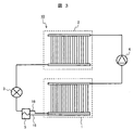
- FIG. 3 shows a schematic configuration of the heat pump system of the present embodiment.
- the heat pump system 10 includes a heat exchanger 1, a condenser 2, an expansion valve 3, a compressor 4, a gas-liquid separator 5, and the like.
- the condenser 2 recondenses the refrigerant by exchanging heat between an external working fluid such as air or water and the refrigerant compressed by the compressor 4.
- the recondensed refrigerant is sent to the expansion valve 3.
- the expansion valve 3 adiabatically expands the refrigerant recondensed by the condenser 2.
- the refrigerant adiabatically expanded becomes a gas-liquid two-phase flow and flows into the gas-liquid separator 5.
- the gas-liquid separator 5 the refrigerant is separated into liquid and gas and flows into the heat exchanger 1 through the liquid pipe 15 and the gas pipe 16.
- the gas-liquid separator 5 is disposed outside the heat exchanger 1.
- the present invention is not limited to this, and the gas-liquid separator 5 is disposed on the heat exchanger 1. It may be arranged inside. Moreover, you may attach the gas-liquid separator 5 to the inlet header 11 of FIG. Further, the gas-liquid separator 5 may be integrated with the inlet header 11 of FIG.
- the liquid refrigerant that has flowed into the heat exchanger 1 is evenly distributed to the plurality of heat transfer tubes 13, and then forms a slag flow with the gas refrigerant that has flowed from the holes 131 to exchange heat with high-temperature air. Then vaporize. Thereafter, the vaporized refrigerant joins again at the outlet header 12 and the outlet pipe 17, is compressed by the compressor 4, and then flows into the condenser 2 again.
- the refrigerant separated into the liquid and the gas by the gas-liquid separator 5 is separately put into the liquid reservoir 115 and the gas reservoir 116 of the heat exchanger 1, and is stored in each heat transfer tube 13. Refrigerant is sent evenly. For this reason, the heat exchanger tube 13 can be functioned without waste, and the efficiency of the heat exchanger 1 can be improved.
- a gas-liquid two-phase slag flow can be formed in the heat transfer tube 13 by reintroducing the gas refrigerant from the hole 131 of the heat transfer tube 13.
- the slag flow as compared with the liquid single-phase flow, evaporation occurs in a thin liquid film layer between the slag bubbles and the wall surface of the heat transfer tube 13, so that the heat transfer coefficient is increased. Therefore, heat from high-temperature air is efficiently transferred to the liquid refrigerant, and a heat exchanger with high heat transfer performance can be obtained.
- the tube diameter of the heat transfer tube 13 is small.
- the inner diameter is 1.0 mm or less. It is preferable to make it 0.5 mm or less.
- the hydraulic equivalent diameter may be 1.0 mm or less. Also in this case, it is more preferable that the thickness is 0.5 mm or less.
- the inner diameter of the circular tube and the hydraulic equivalent diameter other than the circular tube are both referred to as “inner diameter”.
- the lower limit of the tube diameter needs to be determined in consideration of these influences from the physical properties of the refrigerant used.
- the heat pump system 10 needs to determine the circulation amount of the refrigerant according to its capacity.
- the length of each heat transfer tube 13 shown in FIG. 1 is desirably 200 mm or less, and more desirably 100 mm or less, from the viewpoint of the pressure loss of the liquid refrigerant.
- FIG. 4 is a perspective view showing a heat exchanger according to the second embodiment.
- the present embodiment is different from the first embodiment in that gas / liquid separation is not performed before the refrigerant flows in, and the refrigerant flows into the heat exchanger 1 from the inlet pipe 18.
- the gas-liquid separator 5 of FIG. 3 is not used in this embodiment as shown in FIG.
- the internal structure of the inlet header 11 is as shown in FIG. Other configurations are the same as those of the first embodiment.
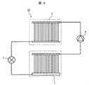
- FIG. 5 shows a configuration of the heat pump system 10 of the present embodiment.
- Example 1 As shown in this figure, the gas-liquid separator used in Example 1 is not used. For this reason, a refrigerant
- the operation of the heat pump system 10 in the present embodiment is as follows.
- the refrigerant whose pressure has been increased by the compressor 4 flows into the condenser 2, where it is condensed and liquefied.
- the liquid refrigerant is adiabatically expanded by the expansion valve 3 and becomes a gas-liquid two-phase flow. Thereafter, it flows into the heat exchanger 1.
- the refrigerant evaporated in the heat exchanger 1 is again pressurized by the compressor 4 and sent to the condenser 2.
- FIG. 6 shows the internal structure of the inlet header 11 of FIG.
- FIG. 6 is a cross-sectional view including the line segment AA ′ in FIG. 4 as viewed in the direction of the arrow. 6 indicates the direction of gravity, as in FIG.
- each heat transfer tube 13 is provided with a hole 131 in a portion where the gas refrigerant accumulates, so that the gas refrigerant flows into the heat transfer tube 13.
- the liquid refrigerant flowing into the inlet header 11 does not evaporate in the inlet header 11 and is accumulated in the inlet header 11.
- the surface is higher than the lower end of the heat transfer tube 13.
- the liquid refrigerant flows from the lower end portion of the heat transfer tube 13.
- the heat transfer tube 13 inside the inlet header 11 has a hole 131 (through hole) provided so that the gas refrigerant flows into the heat transfer tube 13, the gas refrigerant flows from the hole 131.
- the liquid refrigerant and gas refrigerant merge again. Thereby, a two-phase slag flow can be formed, and the heat transfer coefficient can be increased as compared with a liquid single-phase flow.
- the lower end of the heat transfer tube 13 is preferably closer to the bottom surface of the inlet header 11.
- the liquid refrigerant accumulated in the refrigerant reservoir 181 reaches the lower end of the heat transfer tube 13 at an early stage. Assuming that the inlet header 11 is installed horizontally, it is desirable that the lower end portions of all the heat transfer tubes 13 have the same height. Thereby, the liquid level of the liquid refrigerant accumulated in the refrigerant reservoir 181 reaches the lower ends of all the heat transfer tubes 13 almost simultaneously.
- the inlet pipe 18 does not penetrate into the inlet header 11, it is indicated by a broken line in order to clarify the connection position in the inlet header 11.
- the liquid level of the refrigerant is also indicated by a broken line.
- the volume of the refrigerant reservoir 181 is such that the refrigerant level is higher than the lower end of the heat transfer tube 13 and lower than the hole 131.
- the position of the lower end portion of the heat transfer tube 13 and the hole 131 is set sufficiently large.
- the inlet pipe 18 is connected to the upper part of the side part of the refrigerant reservoir 181. It is considered that the liquid refrigerant flowing from the inlet pipe 18 into the refrigerant storage unit 181 hardly disturbs the liquid level of the liquid refrigerant stored in the lower part of the refrigerant storage unit 181 when arranged in this way.
- a partition that serves as a baffle plate (not shown) is provided once for the liquid refrigerant flowing into the refrigerant reservoir 181 from the inlet pipe 18.
- the flow direction of the liquid refrigerant flowing from the inlet pipe 18 into the refrigerant reservoir 181 may be bent so that the liquid refrigerant meanders. In this case, even if the connection position of the inlet pipe 18 is not the upper part of the side surface part of the refrigerant storage part 181, the liquid level of the liquid refrigerant can be stabilized.
- Example 3 will be described with reference to FIGS.
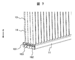
- FIG. 7 is a partial perspective view showing the vicinity of the inlet header of the heat exchanger of the present embodiment.
- the cross section of the inlet header 11 inside the connection part of the inlet piping 18 of the inlet header 11 is shown so that the inside of the inlet header 11 can be understood.
- a convex portion 182 is provided below the refrigerant storage portion 181.
- the lower end portion of the heat transfer tube 13 is disposed below the upper surface portion of the convex portion 182. In other words, the lower end portion of the heat transfer tube 13 is inserted into the groove 183 between the convex portions 182.
- FIG. 8 is a partial cross-sectional view showing the bottom of the inlet header 11 in FIG. 7 (inside the inlet header 11).
- each of the convex portions 182 has a rectangular parallelepiped shape, and a lattice-like groove 183 is formed therebetween.
- the heat transfer tube 13 is disposed in the groove 183 between the convex portions 182 (in the drawing, the portion where the two grooves 183 intersect).
- the convex part 182 may be produced by casting together with the bottom part of the inlet header 11, or may be produced by press-molding a plate-like member. Press molding is desirable in that the inlet header 11 can be reduced in weight.
- the liquid level of the refrigerant can be maintained above the inlet of the heat transfer tube 13 even when the refrigerant is less than that in the second embodiment. Therefore, the amount of refrigerant sealed in the heat pump system 10 (FIG. 5) can be reduced.
- the present invention is not limited to the above-described embodiments, and includes various modifications. Further, a part of the configuration of one embodiment can be replaced with the configuration of another embodiment, and the configuration of another embodiment can be added to the configuration of one embodiment. Further, the above-described embodiments have been described in detail for easy understanding of the present invention, and are not necessarily limited to those having all the configurations described.
Landscapes
- Engineering & Computer Science (AREA)
- Physics & Mathematics (AREA)
- Thermal Sciences (AREA)
- Mechanical Engineering (AREA)
- General Engineering & Computer Science (AREA)
- Chemical & Material Sciences (AREA)
- Analytical Chemistry (AREA)
- Power Engineering (AREA)
- Details Of Heat-Exchange And Heat-Transfer (AREA)
- Heat-Exchange Devices With Radiators And Conduit Assemblies (AREA)
Abstract
入口ヘッダと、出口ヘッダと、これらの間に配置された複数の伝熱管と、を備えた熱交換器であって、伝熱管の内部は、冷媒の流路であり、伝熱管の下端部は、入口ヘッダの内部に配置され、入口ヘッダの内部にある伝熱管は、伝熱管の内部にガス冷媒が流入するように設けられた貫通孔を有する。これにより、複数の伝熱管を有する熱交換器において、それぞれの伝熱管に分配して供給する冷媒の気液比の均一化を図るとともに、伝熱管入口で二相流を形成させて伝熱性能を高めることができる。
Description
本発明は、気液二相流となる冷媒を用いる熱交換器に関する。
近年、ヒートポンプシステムに用いられる熱交換器は、管外の通風抵抗低減および管内伝熱性能向上を目的として、伝熱管の細径化が進んでいる。細径化に伴って、伝熱管内の圧力損失が増加するため、複数の伝熱管を組み合わせて流路を並列に構成することで、圧力損失を低減させている。
従来の熱交換器としては、例えば、特許文献1に記載されたものがある。この特許文献1では、複数の微小径の長孔を備える扁平型多穴管と、この扁平型多穴管を平行に複数配置しその両端を固定するヘッダと、前記扁平型多穴管と接触して配置されるコルゲートフィンとを有する、空冷式のマイクロチューブ型熱交換器が示されている。この特許文献1では、各長孔内を平行に冷媒が流れる構成となっている。
また、その他の熱交換器の例として、例えば、特許文献2に記載されたものがある。この特許文献2では、上下方向に離設した入口ヘッダと出口ヘッダ間を複数本の伝熱細管で連結し、伝熱細管部にメッシュフィンを設けてなる多パス型熱交換器において、入口ヘッダ開口部と出口ヘッダ開口部とを所定の長さの気液分離筒で連結するとともに、気液分離筒上部に気液2相冷媒の供給管を接続した気液分離型熱交換器が示されている。
特許文献1に記載されているような多並列の熱交換器では、入口側のヘッダから流入した気液二相流の冷媒が各長孔に分配される際に、均等な気液比で分配できない課題があった。このため、液冷媒が他の長孔に比べて少なく分配された長孔では、外部空気側からの熱で液冷媒がすぐに蒸発してしまい、長孔内の温度が上昇するために、熱交換性能が低下する問題があった。さらに、液冷媒が他の長孔に比べて多く分配された長孔では、液冷媒がすべて蒸発しきれないため、下流側の圧縮機で液圧縮が発生し、圧縮機が破損する可能性がある課題があった。
また、特許文献2に記載されているような出入口ヘッダ間を気液分離器でバイパスさせる熱交換器では、伝熱管には液冷媒のみが流入するため、冷媒の分配は均一化できる。しかしながら、伝熱管入口付近においては、液単相状態であるために、二相流状態に比べて冷媒側の伝熱性能が低下し、外部空気側からの熱が冷媒に効率よく伝わらない課題があった。
本発明の目的は、複数の伝熱管を有する熱交換器において、それぞれの伝熱管に分配して供給する冷媒の気液比の均一化を図り、かつ、伝熱管における伝熱性能を高めることにある。
上記目的を達成するために、本発明の熱交換器は、入口ヘッダと、出口ヘッダと、これらの間に配置された複数の伝熱管と、を備え、伝熱管の内部は、冷媒の流路であり、伝熱管の下端部は、入口ヘッダの内部に配置され、入口ヘッダの内部にある伝熱管は、伝熱管の内部にガス冷媒が流入するように設けられた貫通孔を有する。
本発明によれば、複数の伝熱管を有する熱交換器において、それぞれの伝熱管に分配して供給する冷媒の気液比の均一化を図るとともに、伝熱管入口で二相流を形成させて伝熱性能を高めることができる。
本発明は、冷媒の相変化を用いたヒートポンプにおいて、内部に低温の気液二相流の冷媒を流し、外部の高温熱源と熱交換を行うために用いられる熱交換器に関する。ヒートポンプは、冷蔵庫、給湯器、空気調和機等に適用される。
以下、本発明の熱交換器に係る具体的な実施例について、図面を用いて説明する。各図において、同一符号を付した部分は、同一の或いは相当する部分を示している。
本実施例1は、図1~図3を用いて説明する。
まず、図1により、本実施例の熱交換器の構成を説明する。
図1は、本実施例の熱交換器を示す斜視図である。
図1において、熱交換器1は、入口ヘッダ11、出口ヘッダ12、複数の伝熱管13、フィン14、液配管15、ガス配管16、出口配管17などを備えている。図1中のgは、重力の方向を示している。入口ヘッダ11と出口ヘッダ12との間には、複数の伝熱管13及びフィン14が配置されている。フィン14は、伝熱管13の外部との伝熱特性を向上するためのものである。
入口ヘッダ11には、複数の伝熱管13、液配管15及びガス配管16が接続されている。本実施例では、入口ヘッダ11は、液配管15及びガス配管16から流入する冷媒を複数の伝熱管13へ流すことができるように構成されている。そして、伝熱管13を通過した冷媒は、出口ヘッダ12を通過し、出口配管17に流出するようになっている。
図2は、図1の入口ヘッダ11の内部構造を示す断面図である。図2は、図1の線分AA’を含む断面を矢印の方向に見たものである。図2中のgは、図1と同様に重力方向を示している。
図2においては、入口ヘッダ11は、液溜部115とガス溜部116とに分けられている。伝熱管13は、入口ヘッダ11の上部からガス溜部116を貫通し、液溜部115に達している。伝熱管13のガス溜部116の領域には、穴131(貫通孔)が設けられ、ガス冷媒が伝熱管13に流入するようになっている。言い換えると、穴131(貫通孔)は、伝熱管13の外壁面から内壁面に貫通している。
なお、液配管15及びガス配管16は、入口ヘッダ11内まで貫通していないが、液溜部115及びガス溜部116との位置関係を明瞭にするため、破線で示している。
冷媒は、熱交換器1へ流入する前に、熱交換器1の上流側に配置された気液分離器により、液冷媒とガス冷媒とに分離される。分離された液冷媒は液配管15から液溜部115へ、ガス冷媒はガス配管16からガス溜部116へ、それぞれ流入し、伝熱管13へ流れる。したがって、入口ヘッダ11内に入った液冷媒及びガス冷媒は、入口ヘッダ11内では気液分離されたままの状態となっている。入口ヘッダ11内に流入した液冷媒は、伝熱管13の下端部から伝熱管13に流入する。一方、入口ヘッダ11内に流入したガス冷媒は、穴131から伝熱管13に流入する。
液冷媒が伝熱管13に流入する前に入口ヘッダ11内で気化すると、複数の伝熱管13における一様な冷媒分配に影響を与える。これを防止するため、入口ヘッダ11は、外気となるべく熱交換せずに伝熱管13へ冷媒を輸送するのがよい。したがって、入口ヘッダ11の材質は、主に外気と熱交換を行う伝熱管13と比べて熱伝導率の低い材料がよく、例えば樹脂材またはステンレス鋼が好適である。なお、入口ヘッダ11を、伝熱管13と同様、銅等の熱伝導率が高い材料で形成した場合であっても、入口ヘッダ11の周囲を断熱材等で覆うことにより、入口ヘッダ11における液冷媒の気化を防止することができる。
次に、入口ヘッダ11から伝熱管13への冷媒の移動について説明する。
伝熱管13入口は、液溜部115とつながっているため、伝熱管13の管入口(下端部)では、まず、液冷媒が流入する。その後、ガス溜部116内にある、伝熱管13に設けた穴131からガス冷媒が伝熱管13へ流入する。したがって、伝熱管13内では、冷媒は、再び二相流として流れる。
伝熱管13は、入口ヘッダ11と出口ヘッダ12との間に配置されている。また、伝熱管13の管外は、フィン14と接続されており、フィン14周囲の空気と伝熱管13内部の冷媒とを熱交換させ、冷媒を気化することができる。このため、伝熱管13は、熱伝導率の高い材料、例えば銅やアルミニウムが好適である。
本実施例においては、伝熱管13は、円管であるが、楕円形の管や四角形の管等、他の管形状としてもよい。また、棒材の長手方向に複数の長孔を設け、それぞれの長孔を管として伝熱管13を構成してもよい。伝熱管13は、入口途中でガス冷媒を導入できるよう、穴131が開けられている。穴131の形状や大きさ、数、位置は、本実施例に限定されるものではなく、液冷媒がガス溜部116へ逆流せず、かつ、冷媒が伝熱管13内でスラグ流を形成して出口ヘッダ12へ流れるように、伝熱管13の内径、冷媒の流量、圧縮機の動力等に応じて適切に設計することができる。
出口ヘッダ12では、複数の伝熱管13でガス化したガス冷媒が再合流し、出口配管17へ流れる。出口ヘッダ12へ流入する冷媒は、ガス単相であるため、入口ヘッダ11のように液溜部とガス溜部のような区切りは必要ない。出口ヘッダ12の材質は、液冷媒の気化を抑制する必要がないため、樹脂材やステンレス鋼で無くてもよく、断熱材も不要である。
フィン14は、高温空気からの熱を効率よく伝熱管13内の冷媒へ伝える必要がある。
このため、フィン14も、伝熱管13と同様、アルミニウムや銅などの熱伝導率の高い材料で構成されることが望ましい。また、外部の空気とフィン14との熱伝達率を向上させるために、フィン14に溝やスリット等を設けてもよい。
このため、フィン14も、伝熱管13と同様、アルミニウムや銅などの熱伝導率の高い材料で構成されることが望ましい。また、外部の空気とフィン14との熱伝達率を向上させるために、フィン14に溝やスリット等を設けてもよい。
フィン14と伝熱管13との接続部では、熱を効率よく伝える必要がある。このために、例えば、あらかじめ開けたフィン14の穴に伝熱管13を挿入し、その後、伝熱管13を拡管してフィン14と伝熱管13との接触部分の面圧を大きくするか、熱伝導性の高い接着剤やグリス等で接続部分の隙間を埋める、または溶接やロウ付け、はんだ付け等により一体化させるのが好ましい。本実施例では、冷媒は空気と熱交換するためにフィン14を設けたが、例えば高温水や熱源と接続されたヒートシンク等、別の流体・固体と熱交換を行う場合も考えられる。その場合は、熱交換する高温媒体に応じて、フィン14をシェルチューブ熱交換器のように流体を流す流路とすること、又はヒートシンクと一体化させることが好ましい。
液配管15、ガス配管16及び出口配管17は、熱交換器1と圧縮機や膨張弁等の他の装置とを接続するために設けられている。これらの材質は、無駄な熱侵入や熱放出がないよう、外部との熱交換のない断熱状態を維持できるものが好ましい。しかし、例えば一般の空気調和機等においては装置の位置や配管の長さが設置場所により異なる。したがって、断熱維持に加えて加工しやすい材料がよく、銅等の加工が容易な材料とし、外周を図示しない断熱材で囲むことでより、効率が高いヒートポンプシステムとすることができる。
次に、本実施例のヒートポンプシステムの構成と動作について図3を用いて説明する。
図3は、本実施例のヒートポンプシステムの概略構成を示したものである。
本図に示すように、ヒートポンプシステム10は、熱交換器1、凝縮器2、膨張弁3、圧縮機4、気液分離器5等から構成されている。
凝縮器2は、空気や水等の外部作動流体と、圧縮機4により圧縮された冷媒とを熱交換させることにより、冷媒を再凝縮させるものである。再凝縮した冷媒は、膨張弁3に送られる。膨張弁3は、凝縮器2で再凝縮した冷媒を断熱膨張させる。断熱膨張した冷媒は、気液二相流となり、気液分離器5へ流入する。気液分離器5では、冷媒は、液とガスとに分離され、液配管15及びガス配管16を通って熱交換器1へ流入する。なお、図3においては、気液分離器5を熱交換器1の外部に配置しているが、本発明は、これに限定されるものではなく、気液分離器5を熱交換器1の内部に配置してもよい。また、気液分離器5は、図1の入口ヘッダ11に付設してもよい。さらに、気液分離器5は、図1の入口ヘッダ11と一体化してもよい。
図2に示すように、熱交換器1に流入した液冷媒は、複数の伝熱管13に均等に分配された後、穴131から流入したガス冷媒とスラグ流を形成し、高温空気と熱交換して気化する。その後、気化した冷媒は、出口ヘッダ12及び出口配管17で再び合流し、圧縮機4により圧縮された後、再度凝縮器2へ流入する。
本実施例によれば、気液分離器5により液とガスとに分離された冷媒が、熱交換器1の液溜部115およびガス溜部116に分けて入れられ、各伝熱管13内の冷媒が均等に送られる。このため、伝熱管13を無駄なく機能させることができ、熱交換器1の効率を高めることができる。
さらに、伝熱管13の穴131からガス冷媒を再導入することで、伝熱管13内に気液二相のスラグ流を形成することができる。スラグ流では、液単相流と比較して、スラグ気泡と伝熱管13壁面との間の薄い液膜層で蒸発が起きるため、熱伝達率が大きくなる。したがって、高温空気からの熱が効率よく液冷媒へ伝わり、伝熱性能の高い熱交換器とすることができる。
伝熱管13を流れる液冷媒への熱伝達性を向上するためには、伝熱管13の管径が小さいほどよく、伝熱管13が円管の場合には、その内径は、1.0mm以下にすることが好ましく、0.5mm以下とすることが更に好ましい。また、伝熱管13が円管以外の場合には、その水力等価直径(冷媒流路の直径)は、1.0mm以下とすればよい。この場合も、0.5mm以下とすれば更に好ましい。なお、本明細書においては、円管の内径及び円管以外の水力等価直径をともに「内径」と呼ぶことにする。
管径を小さくするのに伴って、冷媒の流動に伴う圧力損失の増加や、伝熱管13が閉塞する可能性がある。したがって、管径の下限は、使用する冷媒の物性からこれらの影響を考慮して決める必要がある。
なお、ヒートポンプシステム10は、その能力によって冷媒の循環量を定める必要がある。例えば、数百W程度の小型のヒートポンプシステムであれば、図1に示す伝熱管13のそれぞれの長さは、液冷媒の圧力損失の観点から、200mm以下が望ましく、100mm以下が更に望ましい。
また、熱交換器1が若干傾き、入口ヘッダ11が水平を保っていない場合であっても、本実施例においては、液溜部115とガス溜部116とに分けられているため、液冷媒の均一分配を維持することができる。
本実施例2は、図4~図6を用いて説明する。
図4は、本実施例2の熱交換器を示す斜視図である。
図4に示すように、本実施例では、冷媒が流入する前に気液分離を行わず、冷媒を入口配管18から熱交換器1へ流入させる点が実施例1と異なる。この違いに対応して、図3の気液分離器5は、後述の図5に示すとおり、本実施例においては用いていない。また、入口ヘッダ11の内部構造は、後述の図6に示すとおりとしている。その他の構成は、実施例1と同様である。
図5は、本実施例のヒートポンプシステム10の構成を示したものである。
本図に示すように、実施例1で用いている気液分離器は、用いていない。このため、冷媒は、気液二相流状態のまま熱交換器1へ流入する。
本実施例におけるヒートポンプシステム10の動作は、次のとおりである。
図5において、圧縮機4で昇圧された冷媒は、凝縮器2に流れ、凝縮され、液化する。
液冷媒は、膨張弁3で断熱膨張し、気液二相流となる。その後、熱交換器1へ流入する。
熱交換器1において気化した冷媒は、再び、圧縮機4で昇圧され、凝縮器2に送られる。
液冷媒は、膨張弁3で断熱膨張し、気液二相流となる。その後、熱交換器1へ流入する。
熱交換器1において気化した冷媒は、再び、圧縮機4で昇圧され、凝縮器2に送られる。
図6は、図4の入口ヘッダ11の内部構造を示したものである。図6は、図4の線分AA’を含む断面を矢印の方向に見たものである。図6中のgは、図4と同様に重力方向を示している。
図6においては、入口ヘッダ11の内部に仕切りはなく、冷媒貯留部181が設けられている。入口ヘッダ11の上部を貫通した複数の伝熱管13は、冷媒貯留部181の液冷媒が溜まる部分に達するように配置されている。また、それぞれの伝熱管13には、ガス冷媒が溜まる部分に穴131が設けられ、ガス冷媒が伝熱管13に流入するようになっている。言い換えると、通常、入口ヘッダ11内に流入する液冷媒は、入口ヘッダ11内ですべてが蒸発することはなく、入口ヘッダ11内に蓄積されるため、定常運転に達するまでには、冷媒の液面が伝熱管13の下端部より高くなる。よって、伝熱管13の下端部は、入口ヘッダ11の内部に配置されていれば、液冷媒が伝熱管13の下端部から流入することになる。そして、入口ヘッダ11の内部にある伝熱管13は、伝熱管13の内部にガス冷媒が流入するように設けられた穴131(貫通孔)を有するため、ガス冷媒が穴131から流入することにより、一旦分離された液冷媒とガス冷媒とが再度合流する。これにより、二相のスラグ流を形成することができ、液単相流と比較して、熱伝達率を大きくすることができる。なお、伝熱管13の下端部は、入口ヘッダ11の底面に近いほど望ましい。冷媒貯留部181に蓄積される液冷媒が早期に伝熱管13の下端部に達するようになるからである。なお、入口ヘッダ11が水平に設置されることを前提として、すべての伝熱管13の下端部は、同じ高さとすることが望ましい。これにより、冷媒貯留部181に蓄積される液冷媒の液面がほぼ同時にすべての伝熱管13の下端部に達するようになる。
図5に示す膨張弁3を通過した気液二相流の冷媒は、入口配管18から冷媒貯留部181へ流入する。入口配管18は、入口ヘッダ11内まで貫通していないが、入口ヘッダ11における接続位置を明瞭にするため、破線で示している。また、冷媒の液面も破線で示している。図6に示すように、定常的な運転時には、冷媒の液面が伝熱管13の下端部より高く、かつ、穴131より低い位置となるように、冷媒貯留部181の体積が冷媒の循環量に比べて十分大きい構成とし、伝熱管13の下端部及び穴131の位置を設定している。このような構成とすることによって、冷媒貯留部181内においては、冷媒が気液密度差により自動的に分離される。
また、図6においては、入口配管18は、冷媒貯留部181の側面部のうち上部に接続している。このように配置したほうが、入口配管18から冷媒貯留部181に流入する液冷媒が冷媒貯留部181の下部に溜まっている液冷媒の液面を乱すことが少ないと考えられる。
なお、液冷媒の液面の乱れを抑制するためには、入口配管18から冷媒貯留部181に流入する液冷媒に対してじゃま板(図示していない。)となる仕切りを設けることにより、一旦、入口配管18から冷媒貯留部181に流入する液冷媒の流れの向きを曲げ、液冷媒が蛇行するようにしてもよい。この場合、入口配管18の接続位置は、冷媒貯留部181の側面部のうち上部としなくても、液冷媒の液面を安定させることができる。
上記以外の構成は、実施例1と同様である。
本実施例のように気液分離器を設けない構成においても、実施例1と同様な効果を得ることができる。
なお、本実施例の入口ヘッダ11(図6)に、実施例1の気液分離器5、液配管15及びガス配管16(図3)を付設してもよい。この場合、冷媒は、液とガスとに分離された状態で、仕切りのない入口ヘッダ11に流入するが、入口ヘッダ11における液配管15の接続位置をガス配管16の接続位置の下方とすることにより、入口ヘッダ11において気液が分離した状態が保たれる。
本実施例3は、図7及び図8を用いて説明する。
図7は、本実施例の熱交換器の入口ヘッダ付近を示す部分斜視図である。本図においては、入口ヘッダ11の内部がわかるように、入口ヘッダ11の入口配管18の接続部よりも内側における入口ヘッダ11の断面を示している。
本実施例では、冷媒貯留部181の下側に凸部182が設けられている。伝熱管13の下端部は、凸部182の上面部より下方に配置されている。言い換えると、伝熱管13の下端部は、凸部182の間の溝183に挿入されている。
図8は、図7の入口ヘッダ11の底部(入口ヘッダ11の内側)を示す部分断面図である。
図8においては、凸部182は、1つ1つが直方体形状を有し、これらの間に格子状の溝183が形成されている。凸部182の間の溝183(本図においては2つの溝183が交わる部位)には、伝熱管13が配置されている。
なお、凸部182は、入口ヘッダ11の底部とともに鋳造により作製してもよいし、板状部材をプレス成形することにより作製してもよい。プレス成形は、入口ヘッダ11を軽量化できる点で望ましい。
このような構成とすることで、実施例2に比べて冷媒が少ない場合でも、冷媒の液面を伝熱管13入口より上方に維持することができる。したがって、ヒートポンプシステム10(図5)に封入する冷媒量を低減することができる。
なお、本発明は、上述した実施例に限定されるものではなく、様々な変形例を含むものである。また、ある実施例の構成の一部を他の実施例の構成に置き換えることが可能であり、ある実施例の構成に他の実施例の構成を加えることも可能である。さらに、上述した実施例は、本発明を分かりやすく説明するために詳細に説明したものであり、必ずしも説明した全ての構成を備えるものに限定されるものではない。
1:熱交換器、2:凝縮器、3:膨張弁、4:圧縮機、5:気液分離器、10:ヒートポンプシステム、11:入口ヘッダ、12:出口ヘッダ、13:伝熱管、14:フィン、15:液配管、16:ガス配管、17:出口配管、18:入口配管、115:液溜部、116:ガス溜部、131:穴、181:冷媒貯留部、182:凸部、183:溝。
Claims (5)
- 入口ヘッダと、
出口ヘッダと、
これらの間に配置された複数の伝熱管と、を備え、
前記伝熱管の内部は、冷媒の流路であり、
前記伝熱管の下端部は、前記入口ヘッダの内部に配置され、
前記入口ヘッダの内部にある前記伝熱管は、前記伝熱管の内部にガス冷媒が流入するように設けられた貫通孔を有する、熱交換器。 - 請求項1に記載の熱交換器であって、
さらに、気液分離器を備えた、熱交換器。 - 請求項1又は2に記載の熱交換器であって、
前記入口ヘッダは、液溜部とガス溜部とを有し、
前記伝熱管の下端部は、前記液溜部の内部に配置され、
前記貫通孔は、前記ガス溜部の内部に設けられている、熱交換器。 - 請求項1から3のいずれか一項に記載の熱交換器であって、
前記伝熱管の内径は、1.0mm以下である、熱交換器。 - 請求項1から4のいずれか一項に記載の熱交換器であって、
前記入口ヘッダの底部には、凸部が設けられている、熱交換器。
Priority Applications (2)
| Application Number | Priority Date | Filing Date | Title |
|---|---|---|---|
| JP2018520670A JP6678235B2 (ja) | 2016-06-02 | 2017-03-13 | 熱交換器 |
| DE112017002266.5T DE112017002266T5 (de) | 2016-06-02 | 2017-03-13 | Wärmetauscher |
Applications Claiming Priority (2)
| Application Number | Priority Date | Filing Date | Title |
|---|---|---|---|
| JP2016-110991 | 2016-06-02 | ||
| JP2016110991 | 2016-06-02 |
Publications (1)
| Publication Number | Publication Date |
|---|---|
| WO2017208558A1 true WO2017208558A1 (ja) | 2017-12-07 |
Family
ID=60479277
Family Applications (1)
| Application Number | Title | Priority Date | Filing Date |
|---|---|---|---|
| PCT/JP2017/009897 WO2017208558A1 (ja) | 2016-06-02 | 2017-03-13 | 熱交換器 |
Country Status (3)
| Country | Link |
|---|---|
| JP (1) | JP6678235B2 (ja) |
| DE (1) | DE112017002266T5 (ja) |
| WO (1) | WO2017208558A1 (ja) |
Cited By (3)
| Publication number | Priority date | Publication date | Assignee | Title |
|---|---|---|---|---|
| CN110285603A (zh) * | 2018-03-19 | 2019-09-27 | 松下知识产权经营株式会社 | 热交换器和使用其的制冷系统 |
| WO2020237960A1 (zh) * | 2019-05-31 | 2020-12-03 | 浙江三花智能控制股份有限公司 | 分配管和换热器 |
| JPWO2020230268A1 (ja) * | 2019-05-14 | 2021-11-11 | 三菱電機株式会社 | 熱交換器及び冷凍サイクル装置 |
Families Citing this family (1)
| Publication number | Priority date | Publication date | Assignee | Title |
|---|---|---|---|---|
| CN115371463A (zh) * | 2022-08-03 | 2022-11-22 | 西安交通大学 | 一种双排微通道换热器及其控制方法 |
Citations (6)
| Publication number | Priority date | Publication date | Assignee | Title |
|---|---|---|---|---|
| JPH10267468A (ja) * | 1997-03-25 | 1998-10-09 | Mitsubishi Electric Corp | 分配ヘッダー |
| JP2005172373A (ja) * | 2003-12-12 | 2005-06-30 | Calsonic Kansei Corp | 蒸発器 |
| JP2005299989A (ja) * | 2004-04-09 | 2005-10-27 | T Rad Co Ltd | 熱交換器用タンク |
| JP2009133567A (ja) * | 2007-11-30 | 2009-06-18 | Calsonic Kansei Corp | 気液分離器及び空気調和装置 |
| JP2014070860A (ja) * | 2012-10-01 | 2014-04-21 | Keihin Thermal Technology Corp | 熱交換器 |
| JP2016038115A (ja) * | 2014-08-05 | 2016-03-22 | サンデンホールディングス株式会社 | 熱交換器 |
Family Cites Families (2)
| Publication number | Priority date | Publication date | Assignee | Title |
|---|---|---|---|---|
| JPH0660661B2 (ja) | 1984-07-03 | 1994-08-10 | トヨタ自動車株式会社 | トルク変動吸収クラツチ |
| JP2001263861A (ja) | 2000-03-17 | 2001-09-26 | Sanyo Electric Co Ltd | 熱交換器 |
-
2017
- 2017-03-13 WO PCT/JP2017/009897 patent/WO2017208558A1/ja active Application Filing
- 2017-03-13 JP JP2018520670A patent/JP6678235B2/ja not_active Expired - Fee Related
- 2017-03-13 DE DE112017002266.5T patent/DE112017002266T5/de not_active Ceased
Patent Citations (6)
| Publication number | Priority date | Publication date | Assignee | Title |
|---|---|---|---|---|
| JPH10267468A (ja) * | 1997-03-25 | 1998-10-09 | Mitsubishi Electric Corp | 分配ヘッダー |
| JP2005172373A (ja) * | 2003-12-12 | 2005-06-30 | Calsonic Kansei Corp | 蒸発器 |
| JP2005299989A (ja) * | 2004-04-09 | 2005-10-27 | T Rad Co Ltd | 熱交換器用タンク |
| JP2009133567A (ja) * | 2007-11-30 | 2009-06-18 | Calsonic Kansei Corp | 気液分離器及び空気調和装置 |
| JP2014070860A (ja) * | 2012-10-01 | 2014-04-21 | Keihin Thermal Technology Corp | 熱交換器 |
| JP2016038115A (ja) * | 2014-08-05 | 2016-03-22 | サンデンホールディングス株式会社 | 熱交換器 |
Cited By (5)
| Publication number | Priority date | Publication date | Assignee | Title |
|---|---|---|---|---|
| CN110285603A (zh) * | 2018-03-19 | 2019-09-27 | 松下知识产权经营株式会社 | 热交换器和使用其的制冷系统 |
| CN110285603B (zh) * | 2018-03-19 | 2021-12-24 | 松下知识产权经营株式会社 | 热交换器和使用其的制冷系统 |
| JPWO2020230268A1 (ja) * | 2019-05-14 | 2021-11-11 | 三菱電機株式会社 | 熱交換器及び冷凍サイクル装置 |
| JP7209821B2 (ja) | 2019-05-14 | 2023-01-20 | 三菱電機株式会社 | 熱交換器及び冷凍サイクル装置 |
| WO2020237960A1 (zh) * | 2019-05-31 | 2020-12-03 | 浙江三花智能控制股份有限公司 | 分配管和换热器 |
Also Published As
| Publication number | Publication date |
|---|---|
| DE112017002266T5 (de) | 2019-01-24 |
| JP6678235B2 (ja) | 2020-04-08 |
| JPWO2017208558A1 (ja) | 2019-02-21 |
Similar Documents
| Publication | Publication Date | Title |
|---|---|---|
| JP5097472B2 (ja) | 熱交換器 | |
| US20150021003A1 (en) | Heat exchanger | |
| JP6678235B2 (ja) | 熱交換器 | |
| US10612856B2 (en) | Heat exchanger and air conditioning system | |
| JP2017044428A (ja) | 熱交換器、分流部品、および熱交換装置 | |
| KR20170067351A (ko) | 열교환기 | |
| JP2021148389A (ja) | 熱交換器 | |
| JP2021148388A (ja) | 熱交換器 | |
| WO2015045105A1 (ja) | 熱交換器及びそれを用いた空気調和機 | |
| WO2017110740A1 (ja) | 放熱装置、それを用いた相変化冷却装置、および放熱方法 | |
| JP2011142298A (ja) | 沸騰冷却装置 | |
| JP6747937B2 (ja) | 熱電発電システム | |
| JP2018179325A (ja) | 熱交換器、および、それを用いたヒートポンプシステム | |
| CN112584671A (zh) | 用于冷却电子构件的均温板 | |
| JP2015092120A (ja) | 凝縮器 | |
| CN113716011B (zh) | 一种船舶用泵辅助冷却系统 | |
| WO2018051611A1 (ja) | 熱交換器およびそれを用いたヒートポンプシステム | |
| Kuznetsov et al. | Comparative analysis of boiling and condensation heat transfer in upflow for freon R-21 in minichannels | |
| CN113758324A (zh) | 用于低压驱动器的回路式热管 | |
| JP2015068560A (ja) | 冷凍サイクル装置の利用側ユニット | |
| WO2017082127A1 (ja) | 電子機器の冷却装置 | |
| US11976854B2 (en) | Enhanced tube for direct expansion evaporators | |
| JP4930472B2 (ja) | 冷却装置 | |
| JP2020115070A (ja) | 熱交換器 | |
| JP7296264B2 (ja) | 熱交換器および冷凍サイクル装置 |
Legal Events
| Date | Code | Title | Description |
|---|---|---|---|
| ENP | Entry into the national phase |
Ref document number: 2018520670 Country of ref document: JP Kind code of ref document: A |
|
| 121 | Ep: the epo has been informed by wipo that ep was designated in this application |
Ref document number: 17806120 Country of ref document: EP Kind code of ref document: A1 |
|
| 122 | Ep: pct application non-entry in european phase |
Ref document number: 17806120 Country of ref document: EP Kind code of ref document: A1 |