WO2017204333A1 - 異物除去装置 - Google Patents
異物除去装置 Download PDFInfo
- Publication number
- WO2017204333A1 WO2017204333A1 PCT/JP2017/019706 JP2017019706W WO2017204333A1 WO 2017204333 A1 WO2017204333 A1 WO 2017204333A1 JP 2017019706 W JP2017019706 W JP 2017019706W WO 2017204333 A1 WO2017204333 A1 WO 2017204333A1
- Authority
- WO
- WIPO (PCT)
- Prior art keywords
- foreign matter
- matter removing
- substrate
- cleaning head
- removing apparatus
- Prior art date
- Legal status (The legal status is an assumption and is not a legal conclusion. Google has not performed a legal analysis and makes no representation as to the accuracy of the status listed.)
- Ceased
Links
Images




Classifications
-
- H—ELECTRICITY
- H10—SEMICONDUCTOR DEVICES; ELECTRIC SOLID-STATE DEVICES NOT OTHERWISE PROVIDED FOR
- H10P—GENERIC PROCESSES OR APPARATUS FOR THE MANUFACTURE OR TREATMENT OF DEVICES COVERED BY CLASS H10
- H10P72/00—Handling or holding of wafers, substrates or devices during manufacture or treatment thereof
- H10P72/04—Apparatus for manufacture or treatment
- H10P72/0402—Apparatus for fluid treatment
- H10P72/0406—Apparatus for fluid treatment for cleaning followed by drying, rinsing, stripping, blasting or the like
-
- B—PERFORMING OPERATIONS; TRANSPORTING
- B08—CLEANING
- B08B—CLEANING IN GENERAL; PREVENTION OF FOULING IN GENERAL
- B08B5/00—Cleaning by methods involving the use of air flow or gas flow
-
- H—ELECTRICITY
- H10—SEMICONDUCTOR DEVICES; ELECTRIC SOLID-STATE DEVICES NOT OTHERWISE PROVIDED FOR
- H10P—GENERIC PROCESSES OR APPARATUS FOR THE MANUFACTURE OR TREATMENT OF DEVICES COVERED BY CLASS H10
- H10P52/00—Grinding, lapping or polishing of wafers, substrates or parts of devices
-
- H—ELECTRICITY
- H10—SEMICONDUCTOR DEVICES; ELECTRIC SOLID-STATE DEVICES NOT OTHERWISE PROVIDED FOR
- H10P—GENERIC PROCESSES OR APPARATUS FOR THE MANUFACTURE OR TREATMENT OF DEVICES COVERED BY CLASS H10
- H10P72/00—Handling or holding of wafers, substrates or devices during manufacture or treatment thereof
- H10P72/30—Handling or holding of wafers, substrates or devices during manufacture or treatment thereof for conveying, e.g. between different workstations
Definitions
- the present invention relates to a foreign substance removing device, and more particularly to a structure of a foreign substance removing device that removes foreign substances on the surface of a flat plate member such as a substrate to be conveyed.
- a die bonding apparatus for bonding a semiconductor die cut from a wafer to a substrate, a wire bonding apparatus for bonding an electrode of a semiconductor die bonded to the substrate and an electrode of the substrate with a wire, and a semiconductor die
- Many devices such as a flip chip mounting apparatus are used in which bumps are formed on the electrodes, the semiconductor die is inverted and fixed to the substrate, and the electrodes of the semiconductor die and the electrodes of the substrate are connected.
- a bonding apparatus for laminating and bonding a semiconductor die on a semiconductor die of a wafer has also been used.
- a semiconductor die is bonded to a predetermined position of the substrate while a substrate or the like is transferred in one direction by a transfer device, or a substrate having a semiconductor die fixed on the surface is transferred to the predetermined position.
- the electrode of the semiconductor die and the electrode of the substrate are connected by a wire.
- the adhesive strength of the adhesive may decrease.
- dust adheres to the surface of the substrate electrode or the semiconductor die electrode a crack or the like may occur in the semiconductor die.
- the foreign matter removing apparatus described in Patent Document 1 removes foreign matter on the surface of the substrate by moving the cleaning nozzle on the substrate moving in the carrying direction in a direction perpendicular to the carrying direction of the substrate. That is, the foreign matter on the surface of the substrate is removed when the substrate on which the foreign matter has adhered passes through the cleaning nozzle moving region, and the surface of the substrate becomes clean on the downstream side in the transport direction of the cleaning nozzle.
- the foreign matter may be blown off downstream in the transport direction. In this case, the foreign matter may reattach to the substrate on the downstream side in the transport direction once cleaned, and the substrate surface may not be sufficiently cleaned.
- an object of the present invention is to improve the cleanliness of the surface of the conveyed flat plate member.
- the foreign matter removing device has a rectangular parallelepiped shape including an injection port for injecting air in a strip shape on the surface of a flat plate member conveyed in the horizontal direction, and a rectangular suction port arranged adjacent to the injection port. And a drive unit that moves the cleaning head along the surface of the flat plate member in a direction orthogonal to the conveying direction, and removes foreign matters on the surface of the flat plate member.
- the suction port side end surface in the longitudinal direction is inclined from the direction orthogonal to the transport direction toward the direction opposite to the transport direction.
- the injection port is preferably inclined with respect to the surface of the flat plate-like member and jets air in a direction toward the suction port.
- the injection port is also suitable as a linear slit.
- the injection port is also preferably a line of holes arranged in a straight line.
- the longitudinal length of the suction port is longer than the longitudinal length of the injection port.
- the drive unit may be suitable for moving the cleaning head by a length set according to the width in the direction orthogonal to the conveying direction of the flat plate member.
- the present invention can improve the cleanliness of the surface of the conveyed flat plate member.
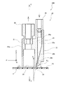
- FIG. 2 is an explanatory perspective view showing a structure of a main body and a lid of the cleaning head of the foreign matter removing apparatus shown in FIG. 1 and an assembly of the lid to the main body. It is the figure which looked at the lower surface in which the suction opening and slit of the cleaning head shown in FIG. 1 are arrange
- the foreign matter removing apparatus 100 includes a cleaning head 20 and a drive unit 30 that moves the cleaning head 20 in a direction orthogonal to the transport direction.
- the transport direction of the substrate 13 which is a flat plate member guided by the guide rails 11 and 12 and transported in the horizontal direction is the X direction
- the direction perpendicular to the X direction on the same plane as the X direction is the Y direction.
- the direction perpendicular to the XY plane will be described as the Z direction.
- the cleaning head 20 has a rectangular parallelepiped shape in which a lid 22 is attached to a rear surface 21b of a main body 21, and an air inlet 25 to which compressed air for removing foreign substances is supplied at an upper portion and a vacuum device (not shown).
- a suction connection pipe 26 to be connected is attached.
- the side with the suction port 24 on the longitudinal surface of the main body 21 is the front surface 21a of the main body 21, the direction perpendicular to the front surface 21a of the main body 21 is the P direction, and the horizontal direction perpendicular to the P direction is the vertical direction.
- the Q direction and the direction perpendicular to the PQ plane will be described as the Z direction.
- the Q direction is a direction parallel to the surface of the main body 21 in plan view.
- the opposite surface of the front surface 21a is described as the rear surface 21b, and the surface in the short side direction is described as the side surface.
- one side surface of the cleaning head 20 is connected to an arm 28 via a wedge-shaped connection member 27.
- the arm 28 reciprocates in the Y direction by the drive unit 30.
- a gap d is opened between the surface of the substrate 13 and the lower surface of the cleaning head 20, and the lower surface of the cleaning head 20 moves along the surface of the substrate 13 on the upper side of the substrate 13.
- the connecting member 27 has an inclination of an angle ⁇ 1, the side surface of the rectangular parallelepiped cleaning head 20 is fixed to one surface, and the surface of the arm 28 extending in the Y direction on the opposite surface. Is fixed. For this reason, as shown in FIG.
- the front surface 21a of the cleaning head 20 is inclined from the Y direction by an angle ⁇ 1 in the direction opposite to the transport direction.
- the angle ⁇ 1 may be about 10 to 15 degrees or about 15 to 45 degrees, for example.
- the angle ⁇ 1 is 10, 11, 12, 13, 14, 15 degrees, and may be a range between any two of these numerical values.
- the angle ⁇ 1 is specifically a positive integer range from 15 to 45, and may be within a range between any two of these numerical values.
- the cleaning head 20 includes a main body 21 and a lid 22 that is fixed to the rear surface 21 b of the main body 21.
- a rectangular suction port 24 is dug in the lower surface of the main body 21.
- a recess 29a that forms a jet header 29 described later is formed on the rear surface 21b of the main body 21.
- the lower side of the recess 29 a is an inclined surface 29 b that is inclined toward the suction port 24.
- the lid 22 includes a flange 22 a that is in close contact with a flat surface other than the recess 29 a of the rear surface 21 b of the main body 21, and a wedge-shaped inclined portion 22 b that is parallel to the inclined surface 29 b of the main body 21. ing.
- the inclined portion 22b of the lid 22 is aligned with the inclined surface 29b of the main body and the flange 22a is screwed to the rear surface 21b as shown in FIG. 3B, the concave portion 29a of the main body 21 and the lid 22 are shown in FIG.
- An injection header 29 extending linearly in the Q direction is formed between the flange 22a.
- a slit 23 is formed between the inclined surface 29 b of the main body 21 and the inclined portion 22 b of the lid 22, which is an injection port for injecting air in a band shape toward the surface of the substrate 13.
- the slit 23 is inclined with respect to the surface of the substrate 13 by an angle ⁇ 2.
- the length of the suction port 24 in the Q direction is longer than the length of the slit 23 in the Q direction, and extends to the vicinity of both side surfaces of the cleaning head 20 from the slit 23.
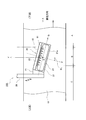
- FIG. 4 is a view of the lower surface of the cleaning head 20 where the suction port 24 and the slit 23 are disposed as viewed from above.
- the operation of the foreign matter removing apparatus 100 configured as described above will be described with reference to FIGS.
- the air jetted obliquely downward from the slit 23 toward the surface of the substrate 13 is directed to the surface of the substrate 13 from the slit 23 toward the P direction inclined in the direction opposite to the conveying direction, as indicated by an arrow 91 in FIG. collide. And the foreign material adhering to the surface of the board
- substrate 13 is blown away toward P direction. The foreign matter blown off is sucked into a rectangular suction port 24 adjacent to the P direction side of the slit 23 and discharged to a vacuum device (not shown).
- the drive unit 30 reciprocates the cleaning head 20 in the Y direction by the width of the substrate 13, the foreign matter in the region B of the substrate 13 shown in FIG. 4 through which the cleaning head 20 has passed is removed.
- the area A on the downstream side in the transport direction of the area B shown in FIG. 4 is an area where foreign matter removal on the surface of the substrate 13 has been completed, and the area C on the upstream side in the transport direction of the area B is a foreign substance on the surface of the substrate 13. This is an area that has not been removed.
- the air ejected from the slit 23 is blown out in the P direction inclined from the Y direction in the direction opposite to the transport direction. That is, air is blown out from the region B toward the region C where the foreign matter is not removed from the substrate 13. For this reason, it is possible to prevent the foreign matter from reattaching to the surface of the substrate 13 in the region A where the foreign matter removal is completed without being blown away in the direction of the region A where the foreign matter removal is finished by the air in which the foreign matter has been ejected. And the cleanliness of the substrate 13 can be improved.
- the length of the suction port 24 in the Q direction is longer than the length of the slit 23 in the Q direction, and extends to the vicinity of both side surfaces of the cleaning head 20 from the slit 23. For this reason, even when the foreign matter is blown away by the air ejected from the slit 23 in the direction inclined from the Y direction to the X direction, the blown foreign matter can be reliably sucked by the suction port 24. For this reason, it can suppress that a foreign material adheres again to the surface of the board
- the reciprocation of the cleaning head 20 in the Y direction may be performed simultaneously with the transport of the substrate 13 or the transport of the substrate 13 may be temporarily stopped and the reciprocation of the cleaning head 20 may be performed. Further, when the width of the substrate 13 in the Y direction changes, the length of the reciprocating movement of the cleaning head 20 in the Y direction may be set to a length set according to the width of the substrate 13 in the Y direction. Thereby, the foreign substance removal apparatus 100 of this embodiment can perform the foreign substance removal of the board
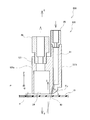
- the foreign matter removing apparatus 200 of the present embodiment is configured such that the slits 23 of the cleaning head 20 of the foreign matter removing apparatus 100 described above are arranged in a row of injection holes 42 arranged linearly. Is.
- the main body 121 of the cleaning head 120 of the foreign matter removing apparatus 200 of the present embodiment includes the suction port 24 dug from the lower side and the injection header 41 dug from the upper side. Yes.
- a suction connection pipe 26 is attached to the upper part of the suction port 24, and an air inlet 25 is attached to the upper part of the jet header 41.
- An injection hole 42 penetrating the injection header 41 is formed in a portion adjacent to the suction port 24 on the lower surface of the main body 121.
- the injection holes 42 are inclined and opened so that the angle with respect to the surface of the substrate 13 is ⁇ 2.
- the injection holes 42 constitute a hole row adjacent to the suction port 24 and arranged in a line in the Q direction.
- the compressed air flowing in from the air inlet 25 shown in FIG. 5 enters the injection header 41, passes through the plurality of injection holes 42 from the injection header 41, and obliquely downwards toward the surface of the substrate 13. It spouts in a strip shape.
- substrate 13 is blown away toward P direction. The blown-off foreign matter is sucked into a rectangular suction port 24 adjacent to the P direction side of the injection hole 42 and discharged to a vacuum device (not shown).
- the drive unit 30 reciprocates the cleaning head 20 in the Y direction by the width of the substrate 13, the foreign matter in the region B of the substrate 13 shown in FIG.
- the area A on the downstream side in the transport direction of the area B shown in FIG. 6 is an area where the foreign matter removal on the surface of the substrate 13 has been completed, and the area C on the upstream side in the transport direction of the area B This is an area that has not been removed.
- the air ejected from the ejection holes 42 is blown out in the P direction inclined from the Y direction in the direction opposite to the transport direction. That is, air is blown out from the region B toward the region C where the foreign matter is not removed from the substrate 13. For this reason, it is possible to prevent the foreign matter from reattaching to the surface of the substrate 13 in the region A where the foreign matter removal is completed without being blown away in the direction of the region A where the foreign matter removal is finished by the air in which the foreign matter has been ejected. And the cleanliness of the substrate 13 can be improved.
- the length of the suction port 24 in the Q direction is longer than the length of the hole array of the injection holes 42 in the Q direction, and extends to the vicinity of both side surfaces of the cleaning head 120 from the injection holes 42. ing. For this reason, even if the foreign matter is blown away by the air ejected from the injection hole 42 in the direction inclined from the Y direction to the X direction, the blown foreign matter can be reliably sucked by the suction port 24. Thereby, it can suppress that a foreign material adheres again to the surface of the board
- the air flows in the direction of the suction port 24 by entraining the air on the rear surface 121 b side of the cleaning head 120. For this reason, the air on the surface of the region A where the removal of the foreign matter in the region adjacent to the region B is completed is sucked toward the suction port 24, and the scattering of the foreign matter from the region B to the region A can be suppressed. Thereby, it is possible to further prevent foreign matters from reattaching to the surface of the substrate 13 in the region A where foreign matter removal has been completed, and the cleanliness of the substrate 13 can be improved.
- the foreign matter removing apparatus 300 of the present embodiment is configured such that the ejection holes 42 of the cleaning head 120 of the foreign matter removing apparatus 200 described above are arranged in a row of vertical ejection holes 43.
- the air ejected from the injection holes 43 is blown in the P direction inclined in the direction opposite to the conveying direction, as in the foreign substance removing apparatus 200 described above. That is, air is blown out from the region B toward the region C where the foreign matter is not removed from the substrate 13. For this reason, it is possible to prevent the foreign matter from reattaching to the surface of the substrate 13 in the region A where the foreign matter removal is completed without being blown away in the direction of the region A where the foreign matter removal is finished by the air in which the foreign matter has been ejected. And the cleanliness of the substrate 13 can be improved.
- the length in the Q direction of the suction port 24 is longer than the length in the Q direction of the hole row of the ejection holes 43, and extends to the vicinity of both side surfaces of the cleaning head 120 from the ejection holes 43. For this reason, even when the foreign matter is blown off in the direction inclined from the Y direction to the X direction by the air ejected from the injection hole 43, the blown foreign matter can be reliably sucked by the suction port 24. Thereby, it can suppress that a foreign material adheres again to the surface of the board
- the foreign matter removing apparatuses 100, 200, and 300 of the present embodiment may be, for example, a semiconductor wafer or a semiconductor die on the substrate.
- the present invention can also be applied when transporting a joined lead frame or the like.
- the foreign matter removing apparatuses 100, 200, and 300 of each embodiment can be incorporated into an electronic component mounting apparatus such as a die bonding apparatus, a wire bonding apparatus, and a flip chip mounting apparatus.
- the foreign matter removing apparatuses 100, 200, and 300 according to the present embodiment can be applied to removing foreign matters on the surface of a flat plate member such as glass or film.
Landscapes
- Cleaning In General (AREA)
- Cleaning Or Drying Semiconductors (AREA)
- Container, Conveyance, Adherence, Positioning, Of Wafer (AREA)
Abstract
Description
Claims (9)
- 水平方向に搬送される平板状部材の表面に帯状に空気を噴射する噴射口と、前記噴射口に隣接して配置される長方形状の吸引口と、を含む直方体状のクリーニングヘッドと、
前記クリーニングヘッドを前記平板状部材の表面に沿って搬送方向と直交方向に移動させる駆動部と、を備え、前記平板状部材の表面の異物を除去する異物除去装置であって、
前記クリーニングヘッドの長手方向の吸引口側端面が、搬送方向と直交方向から搬送方向と反対方向に向かって傾斜している異物除去装置。 - 請求項1に記載の異物除去装置であって、
前記噴射口は、前記平板状部材の表面に対して傾斜し、且つ、前記吸引口に向かう方向に空気を噴出させる異物除去装置。 - 請求項1または2に記載の異物除去装置であって、
前記噴射口は、直線状のスリットである異物除去装置。 - 請求項1または2に記載の異物除去装置であって、
前記噴射口は、直線状に配置された孔列である異物除去装置。 - 請求項1に記載の異物除去装置であって、
前記吸引口の長手方向長さは、前記噴射口の長手方向長さよりも長い異物除去装置。 - 請求項2に記載の異物除去装置であって、
前記吸引口の長手方向長さは、前記噴射口の長手方向長さよりも長い異物除去装置。 - 請求項3に記載の異物除去装置であって、
前記吸引口の長手方向長さは、前記噴射口の長手方向長さよりも長い異物除去装置。 - 請求項4に記載の異物除去装置であって、
前記吸引口の長手方向長さは、前記噴射口の長手方向長さよりも長い異物除去装置。 - 請求項1に記載の異物除去装置であって、
前記駆動部は、前記クリーニングヘッドを前記平板状部材の搬送方向と直交方向の幅に応じて設定された長さだけ移動させる異物除去装置。
Priority Applications (3)
| Application Number | Priority Date | Filing Date | Title |
|---|---|---|---|
| CN201780044149.1A CN109478508A (zh) | 2016-05-27 | 2017-05-26 | 异物去除装置 |
| KR1020187037468A KR102205607B1 (ko) | 2016-05-27 | 2017-05-26 | 이물 제거 장치 |
| JP2018519632A JP6653016B2 (ja) | 2016-05-27 | 2017-05-26 | 異物除去装置 |
Applications Claiming Priority (2)
| Application Number | Priority Date | Filing Date | Title |
|---|---|---|---|
| JP2016-106176 | 2016-05-27 | ||
| JP2016106176 | 2016-05-27 |
Publications (1)
| Publication Number | Publication Date |
|---|---|
| WO2017204333A1 true WO2017204333A1 (ja) | 2017-11-30 |
Family
ID=60412752
Family Applications (1)
| Application Number | Title | Priority Date | Filing Date |
|---|---|---|---|
| PCT/JP2017/019706 Ceased WO2017204333A1 (ja) | 2016-05-27 | 2017-05-26 | 異物除去装置 |
Country Status (5)
| Country | Link |
|---|---|
| JP (1) | JP6653016B2 (ja) |
| KR (1) | KR102205607B1 (ja) |
| CN (1) | CN109478508A (ja) |
| TW (1) | TWI668061B (ja) |
| WO (1) | WO2017204333A1 (ja) |
Cited By (3)
| Publication number | Priority date | Publication date | Assignee | Title |
|---|---|---|---|---|
| KR20190107571A (ko) * | 2018-03-12 | 2019-09-20 | 파스포드 테크놀로지 주식회사 | 다이 본딩 장치 및 반도체 장치의 제조 방법 |
| CN113877891A (zh) * | 2020-07-01 | 2022-01-04 | 帆宣系统科技股份有限公司 | 沾黏吸附式异物去除装置 |
| US12053806B2 (en) | 2020-08-18 | 2024-08-06 | Fasford Technology Co., Ltd. | Die bonding apparatus, cleaning head and manufacturing method for semiconductor device |
Families Citing this family (1)
| Publication number | Priority date | Publication date | Assignee | Title |
|---|---|---|---|---|
| JP7096605B2 (ja) * | 2020-09-03 | 2022-07-06 | 有限会社タクショー | クリーナヘッド |
Citations (2)
| Publication number | Priority date | Publication date | Assignee | Title |
|---|---|---|---|---|
| JPS6292642U (ja) * | 1985-11-29 | 1987-06-13 | ||
| JP2012199458A (ja) * | 2011-03-23 | 2012-10-18 | Hitachi High-Tech Instruments Co Ltd | 異物除去装置及びそれを備えたダイボンダ |
Family Cites Families (5)
| Publication number | Priority date | Publication date | Assignee | Title |
|---|---|---|---|---|
| JPS60184156A (ja) * | 1984-02-29 | 1985-09-19 | 三晃金属工業株式会社 | 既設瓦棒葺屋根の補修屋根 |
| JP4056858B2 (ja) * | 2001-11-12 | 2008-03-05 | 東京エレクトロン株式会社 | 基板処理装置 |
| JP2004074104A (ja) * | 2002-08-22 | 2004-03-11 | Hugle Electronics Inc | 搬送除塵装置 |
| JP4579071B2 (ja) * | 2005-07-06 | 2010-11-10 | ヒューグルエレクトロニクス株式会社 | 基板用搬送除塵装置 |
| JP2013078701A (ja) * | 2010-02-12 | 2013-05-02 | Sharp Corp | 基板処理装置 |
-
2017
- 2017-05-26 KR KR1020187037468A patent/KR102205607B1/ko active Active
- 2017-05-26 TW TW106117601A patent/TWI668061B/zh active
- 2017-05-26 WO PCT/JP2017/019706 patent/WO2017204333A1/ja not_active Ceased
- 2017-05-26 JP JP2018519632A patent/JP6653016B2/ja active Active
- 2017-05-26 CN CN201780044149.1A patent/CN109478508A/zh active Pending
Patent Citations (2)
| Publication number | Priority date | Publication date | Assignee | Title |
|---|---|---|---|---|
| JPS6292642U (ja) * | 1985-11-29 | 1987-06-13 | ||
| JP2012199458A (ja) * | 2011-03-23 | 2012-10-18 | Hitachi High-Tech Instruments Co Ltd | 異物除去装置及びそれを備えたダイボンダ |
Cited By (4)
| Publication number | Priority date | Publication date | Assignee | Title |
|---|---|---|---|---|
| KR20190107571A (ko) * | 2018-03-12 | 2019-09-20 | 파스포드 테크놀로지 주식회사 | 다이 본딩 장치 및 반도체 장치의 제조 방법 |
| KR102185839B1 (ko) | 2018-03-12 | 2020-12-02 | 파스포드 테크놀로지 주식회사 | 다이 본딩 장치 및 반도체 장치의 제조 방법 |
| CN113877891A (zh) * | 2020-07-01 | 2022-01-04 | 帆宣系统科技股份有限公司 | 沾黏吸附式异物去除装置 |
| US12053806B2 (en) | 2020-08-18 | 2024-08-06 | Fasford Technology Co., Ltd. | Die bonding apparatus, cleaning head and manufacturing method for semiconductor device |
Also Published As
| Publication number | Publication date |
|---|---|
| TWI668061B (zh) | 2019-08-11 |
| CN109478508A (zh) | 2019-03-15 |
| KR102205607B1 (ko) | 2021-01-21 |
| TW201808477A (zh) | 2018-03-16 |
| JP6653016B2 (ja) | 2020-02-26 |
| KR20190013903A (ko) | 2019-02-11 |
| JPWO2017204333A1 (ja) | 2019-02-28 |
Similar Documents
| Publication | Publication Date | Title |
|---|---|---|
| US8439478B2 (en) | Ink-jet wiping apparatus, and wiping method using this | |
| JP6389988B2 (ja) | 異物除去装置 | |
| CN102693921B (zh) | 异物除去装置以及具备该装置的芯片接合机 | |
| JP6653016B2 (ja) | 異物除去装置 | |
| TWI573637B (zh) | Cleaning head | |
| JP7129793B2 (ja) | 接合装置 | |
| KR102545475B1 (ko) | 다이 본딩 장치, 클리닝 헤드 및 반도체 장치의 제조 방법 | |
| KR101825231B1 (ko) | 전자 부품의 세정 장치 및 세정 방법 | |
| CN108206147A (zh) | 切断装置 | |
| TWI906411B (zh) | 清洗單元、焊接模組以及焊接設備 | |
| KR20190089182A (ko) | 이물질 제거 장치 및 이물질 제거 방법 | |
| TWI859431B (zh) | 洗淨噴嘴及洗淨方法 | |
| KR102446950B1 (ko) | 기판 세정 모듈 및 이를 구비하는 기판 이송 장치 | |
| JP4933774B2 (ja) | 半導体装置の製造方法 | |
| KR101061979B1 (ko) | 와이어 본딩기 오염물질 제거장치 | |
| KR101939117B1 (ko) | 엑스트라볼 제거용 볼툴 클리너 | |
| US20220250977A1 (en) | Methods and apparatus for manufacturing a glass ribbon | |
| CN109318387A (zh) | 粉尘飞散防止装置及具备该粉尘飞散防止装置的基板加工装置 | |
| JP2005152705A (ja) | 洗浄用スリットノズルおよびこれを備えた洗浄装置 | |
| TW201527025A (zh) | 具乾式潔淨機之板材切斷裝置 | |
| JPH07325311A (ja) | 付着液晶除去装置 |
Legal Events
| Date | Code | Title | Description |
|---|---|---|---|
| DPE1 | Request for preliminary examination filed after expiration of 19th month from priority date (pct application filed from 20040101) | ||
| ENP | Entry into the national phase |
Ref document number: 2018519632 Country of ref document: JP Kind code of ref document: A |
|
| NENP | Non-entry into the national phase |
Ref country code: DE |
|
| 121 | Ep: the epo has been informed by wipo that ep was designated in this application |
Ref document number: 17802919 Country of ref document: EP Kind code of ref document: A1 |
|
| ENP | Entry into the national phase |
Ref document number: 20187037468 Country of ref document: KR Kind code of ref document: A |
|
| 122 | Ep: pct application non-entry in european phase |
Ref document number: 17802919 Country of ref document: EP Kind code of ref document: A1 |