WO2017200041A1 - 速度検出装置 - Google Patents
速度検出装置 Download PDFInfo
- Publication number
- WO2017200041A1 WO2017200041A1 PCT/JP2017/018666 JP2017018666W WO2017200041A1 WO 2017200041 A1 WO2017200041 A1 WO 2017200041A1 JP 2017018666 W JP2017018666 W JP 2017018666W WO 2017200041 A1 WO2017200041 A1 WO 2017200041A1
- Authority
- WO
- WIPO (PCT)
- Prior art keywords
- speed
- range
- vehicle
- relative
- observation range
- Prior art date
- Legal status (The legal status is an assumption and is not a legal conclusion. Google has not performed a legal analysis and makes no representation as to the accuracy of the status listed.)
- Ceased
Links
Images



Classifications
-
- G—PHYSICS
- G01—MEASURING; TESTING
- G01S—RADIO DIRECTION-FINDING; RADIO NAVIGATION; DETERMINING DISTANCE OR VELOCITY BY USE OF RADIO WAVES; LOCATING OR PRESENCE-DETECTING BY USE OF THE REFLECTION OR RERADIATION OF RADIO WAVES; ANALOGOUS ARRANGEMENTS USING OTHER WAVES
- G01S13/00—Systems using the reflection or reradiation of radio waves, e.g. radar systems; Analogous systems using reflection or reradiation of waves whose nature or wavelength is irrelevant or unspecified
- G01S13/02—Systems using reflection of radio waves, e.g. primary radar systems; Analogous systems
- G01S13/50—Systems of measurement based on relative movement of target
- G01S13/58—Velocity or trajectory determination systems; Sense-of-movement determination systems
-
- G—PHYSICS
- G01—MEASURING; TESTING
- G01S—RADIO DIRECTION-FINDING; RADIO NAVIGATION; DETERMINING DISTANCE OR VELOCITY BY USE OF RADIO WAVES; LOCATING OR PRESENCE-DETECTING BY USE OF THE REFLECTION OR RERADIATION OF RADIO WAVES; ANALOGOUS ARRANGEMENTS USING OTHER WAVES
- G01S13/00—Systems using the reflection or reradiation of radio waves, e.g. radar systems; Analogous systems using reflection or reradiation of waves whose nature or wavelength is irrelevant or unspecified
- G01S13/02—Systems using reflection of radio waves, e.g. primary radar systems; Analogous systems
- G01S13/06—Systems determining position data of a target
- G01S13/08—Systems for measuring distance only
- G01S13/10—Systems for measuring distance only using transmission of interrupted, pulse modulated waves
-
- G—PHYSICS
- G01—MEASURING; TESTING
- G01S—RADIO DIRECTION-FINDING; RADIO NAVIGATION; DETERMINING DISTANCE OR VELOCITY BY USE OF RADIO WAVES; LOCATING OR PRESENCE-DETECTING BY USE OF THE REFLECTION OR RERADIATION OF RADIO WAVES; ANALOGOUS ARRANGEMENTS USING OTHER WAVES
- G01S13/00—Systems using the reflection or reradiation of radio waves, e.g. radar systems; Analogous systems using reflection or reradiation of waves whose nature or wavelength is irrelevant or unspecified
- G01S13/02—Systems using reflection of radio waves, e.g. primary radar systems; Analogous systems
- G01S13/06—Systems determining position data of a target
- G01S13/08—Systems for measuring distance only
- G01S13/32—Systems for measuring distance only using transmission of continuous waves, whether amplitude-, frequency-, or phase-modulated, or unmodulated
- G01S13/34—Systems for measuring distance only using transmission of continuous waves, whether amplitude-, frequency-, or phase-modulated, or unmodulated using transmission of continuous, frequency-modulated waves while heterodyning the received signal, or a signal derived therefrom, with a locally-generated signal related to the contemporaneously transmitted signal
-
- G—PHYSICS
- G01—MEASURING; TESTING
- G01S—RADIO DIRECTION-FINDING; RADIO NAVIGATION; DETERMINING DISTANCE OR VELOCITY BY USE OF RADIO WAVES; LOCATING OR PRESENCE-DETECTING BY USE OF THE REFLECTION OR RERADIATION OF RADIO WAVES; ANALOGOUS ARRANGEMENTS USING OTHER WAVES
- G01S13/00—Systems using the reflection or reradiation of radio waves, e.g. radar systems; Analogous systems using reflection or reradiation of waves whose nature or wavelength is irrelevant or unspecified
- G01S13/02—Systems using reflection of radio waves, e.g. primary radar systems; Analogous systems
- G01S13/06—Systems determining position data of a target
- G01S13/08—Systems for measuring distance only
- G01S13/32—Systems for measuring distance only using transmission of continuous waves, whether amplitude-, frequency-, or phase-modulated, or unmodulated
- G01S13/34—Systems for measuring distance only using transmission of continuous waves, whether amplitude-, frequency-, or phase-modulated, or unmodulated using transmission of continuous, frequency-modulated waves while heterodyning the received signal, or a signal derived therefrom, with a locally-generated signal related to the contemporaneously transmitted signal
- G01S13/345—Systems for measuring distance only using transmission of continuous waves, whether amplitude-, frequency-, or phase-modulated, or unmodulated using transmission of continuous, frequency-modulated waves while heterodyning the received signal, or a signal derived therefrom, with a locally-generated signal related to the contemporaneously transmitted signal using triangular modulation
-
- G—PHYSICS
- G01—MEASURING; TESTING
- G01S—RADIO DIRECTION-FINDING; RADIO NAVIGATION; DETERMINING DISTANCE OR VELOCITY BY USE OF RADIO WAVES; LOCATING OR PRESENCE-DETECTING BY USE OF THE REFLECTION OR RERADIATION OF RADIO WAVES; ANALOGOUS ARRANGEMENTS USING OTHER WAVES
- G01S13/00—Systems using the reflection or reradiation of radio waves, e.g. radar systems; Analogous systems using reflection or reradiation of waves whose nature or wavelength is irrelevant or unspecified
- G01S13/02—Systems using reflection of radio waves, e.g. primary radar systems; Analogous systems
- G01S13/50—Systems of measurement based on relative movement of target
- G01S13/58—Velocity or trajectory determination systems; Sense-of-movement determination systems
- G01S13/581—Velocity or trajectory determination systems; Sense-of-movement determination systems using transmission of interrupted pulse modulated waves and based upon the Doppler effect resulting from movement of targets
- G01S13/582—Velocity or trajectory determination systems; Sense-of-movement determination systems using transmission of interrupted pulse modulated waves and based upon the Doppler effect resulting from movement of targets adapted for simultaneous range and velocity measurements
-
- G—PHYSICS
- G01—MEASURING; TESTING
- G01S—RADIO DIRECTION-FINDING; RADIO NAVIGATION; DETERMINING DISTANCE OR VELOCITY BY USE OF RADIO WAVES; LOCATING OR PRESENCE-DETECTING BY USE OF THE REFLECTION OR RERADIATION OF RADIO WAVES; ANALOGOUS ARRANGEMENTS USING OTHER WAVES
- G01S13/00—Systems using the reflection or reradiation of radio waves, e.g. radar systems; Analogous systems using reflection or reradiation of waves whose nature or wavelength is irrelevant or unspecified
- G01S13/02—Systems using reflection of radio waves, e.g. primary radar systems; Analogous systems
- G01S13/50—Systems of measurement based on relative movement of target
- G01S13/58—Velocity or trajectory determination systems; Sense-of-movement determination systems
- G01S13/583—Velocity or trajectory determination systems; Sense-of-movement determination systems using transmission of continuous unmodulated waves, amplitude-, frequency-, or phase-modulated waves and based upon the Doppler effect resulting from movement of targets
- G01S13/584—Velocity or trajectory determination systems; Sense-of-movement determination systems using transmission of continuous unmodulated waves, amplitude-, frequency-, or phase-modulated waves and based upon the Doppler effect resulting from movement of targets adapted for simultaneous range and velocity measurements
-
- G—PHYSICS
- G01—MEASURING; TESTING
- G01S—RADIO DIRECTION-FINDING; RADIO NAVIGATION; DETERMINING DISTANCE OR VELOCITY BY USE OF RADIO WAVES; LOCATING OR PRESENCE-DETECTING BY USE OF THE REFLECTION OR RERADIATION OF RADIO WAVES; ANALOGOUS ARRANGEMENTS USING OTHER WAVES
- G01S13/00—Systems using the reflection or reradiation of radio waves, e.g. radar systems; Analogous systems using reflection or reradiation of waves whose nature or wavelength is irrelevant or unspecified
- G01S13/88—Radar or analogous systems specially adapted for specific applications
- G01S13/93—Radar or analogous systems specially adapted for specific applications for anti-collision purposes
-
- G—PHYSICS
- G01—MEASURING; TESTING
- G01S—RADIO DIRECTION-FINDING; RADIO NAVIGATION; DETERMINING DISTANCE OR VELOCITY BY USE OF RADIO WAVES; LOCATING OR PRESENCE-DETECTING BY USE OF THE REFLECTION OR RERADIATION OF RADIO WAVES; ANALOGOUS ARRANGEMENTS USING OTHER WAVES
- G01S13/00—Systems using the reflection or reradiation of radio waves, e.g. radar systems; Analogous systems using reflection or reradiation of waves whose nature or wavelength is irrelevant or unspecified
- G01S13/88—Radar or analogous systems specially adapted for specific applications
- G01S13/93—Radar or analogous systems specially adapted for specific applications for anti-collision purposes
- G01S13/931—Radar or analogous systems specially adapted for specific applications for anti-collision purposes of land vehicles
-
- G—PHYSICS
- G01—MEASURING; TESTING
- G01S—RADIO DIRECTION-FINDING; RADIO NAVIGATION; DETERMINING DISTANCE OR VELOCITY BY USE OF RADIO WAVES; LOCATING OR PRESENCE-DETECTING BY USE OF THE REFLECTION OR RERADIATION OF RADIO WAVES; ANALOGOUS ARRANGEMENTS USING OTHER WAVES
- G01S13/00—Systems using the reflection or reradiation of radio waves, e.g. radar systems; Analogous systems using reflection or reradiation of waves whose nature or wavelength is irrelevant or unspecified
- G01S13/88—Radar or analogous systems specially adapted for specific applications
- G01S13/93—Radar or analogous systems specially adapted for specific applications for anti-collision purposes
- G01S13/931—Radar or analogous systems specially adapted for specific applications for anti-collision purposes of land vehicles
- G01S2013/932—Radar or analogous systems specially adapted for specific applications for anti-collision purposes of land vehicles using own vehicle data, e.g. ground speed, steering wheel direction
-
- G—PHYSICS
- G01—MEASURING; TESTING
- G01S—RADIO DIRECTION-FINDING; RADIO NAVIGATION; DETERMINING DISTANCE OR VELOCITY BY USE OF RADIO WAVES; LOCATING OR PRESENCE-DETECTING BY USE OF THE REFLECTION OR RERADIATION OF RADIO WAVES; ANALOGOUS ARRANGEMENTS USING OTHER WAVES
- G01S13/00—Systems using the reflection or reradiation of radio waves, e.g. radar systems; Analogous systems using reflection or reradiation of waves whose nature or wavelength is irrelevant or unspecified
- G01S13/88—Radar or analogous systems specially adapted for specific applications
- G01S13/93—Radar or analogous systems specially adapted for specific applications for anti-collision purposes
- G01S13/931—Radar or analogous systems specially adapted for specific applications for anti-collision purposes of land vehicles
- G01S2013/9327—Sensor installation details
- G01S2013/93271—Sensor installation details in the front of the vehicles
-
- G—PHYSICS
- G08—SIGNALLING
- G08G—TRAFFIC CONTROL SYSTEMS
- G08G1/00—Traffic control systems for road vehicles
- G08G1/16—Anti-collision systems
Definitions
- the present disclosure relates to a speed detection device that detects a relative speed of a target from a received signal by an in-vehicle Doppler radar.
- a Doppler radar transmits a radar wave based on a transmission signal that is modulated into a pulse having a constant width and repeated at a constant period, and receives a reflected wave from a target that reflects the radar wave.
- a transmission signal and a reception signal are mixed to generate a mixed signal having phase information of each pulse, thereby detecting a relative velocity corresponding to the phase difference between two pulses. be able to.
- the phase difference exceeds ⁇ 180 °, the relative speed is turned back, and the relative speed is ambiguous.
- the relative velocity corresponding to the 180 ° phase difference is called the Nyquist velocity.
- Non-Patent Document 1 a technique has been used that expands the Nyquist speed and reduces the ambiguity of the relative speed by alternately transmitting the same pulse in two types of cycles. .
- One aspect of the present disclosure can provide a speed detection device that can uniquely detect the relative speed of a target using one type of pulse repetition period.
- One aspect of the present disclosure is an on-vehicle radar that transmits a radar wave based on a transmission signal that is modulated into a pulse with a constant width and repeats at a constant period, and receives a reflected wave from a target that reflects the radar wave.
- a speed detection device that detects a relative speed of a target with respect to a vehicle on which an in-vehicle radar is mounted from a received signal, and includes a speed detection unit, a candidate detection unit, a range setting unit, and a selection unit. Prepare. The speed detector detects the vehicle speed.
- the candidate detection unit detects a candidate for the relative speed according to the phase difference between the plurality of pulses included in the received signal.
- the range setting unit sets the relative speed observation range to a range corresponding to the vehicle speed detected by the speed detection unit and to a range smaller than a width that is twice the Nyquist speed corresponding to the pulse repetition period. To do.
- the selection unit selects, as a relative velocity, a candidate that falls within the observation range set by the range setting unit among the relative velocity candidates detected by the candidate detection unit.
- the relative speed of the target to be watched is determined according to the vehicle speed, so even if the observation range of the relative speed is limited to the vehicle speed, There is no hindrance.
- the observation range can be set to a range smaller than the width that is twice the Nyquist velocity, so the relative velocity that enters the observation range from the detected relative velocity candidates Can be selected uniquely. That is, it is possible to uniquely detect the relative velocity of a target suitable as an observation target using one type of repetition frequency.
- FIG. 1 shows the 1st FFT process with respect to IF signal.
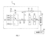
- the radar apparatus 1 includes an oscillator 11, an amplifier 12, a distributor 14, a transmission antenna 16, a reception antenna unit 20, a reception switch 21, an amplifier 22, a mixer 23, a filter 24, and A / D conversion. And a millimeter wave radar mounted on a vehicle.
- the oscillator 11 generates a modulation signal in which a millimeter-wave high-frequency signal having a frequency fc and a wavelength ⁇ c is modulated into a pulse having a certain width and repeated at a certain repetition period ⁇ T in accordance with a command from the processing device 10.
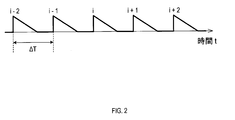
- Each pulse is a coherent pulse, and as shown in FIG. 2, the frequency of the high-frequency signal forming each pulse is modulated so as to decrease linearly at a constant rate within a predetermined band. Therefore, the difference in frequency between the transmission signal Ss and the reception signal Sr includes a change in frequency due to the time from transmission to reception according to the distance to the target and a change in frequency due to the Doppler shift.
- the amplifier 12 amplifies the modulation signal generated by the oscillator 11.
- the distributor 14 distributes the output of the amplifier 12 to the transmission signal Ss and the local signal L.
- the transmission antenna 16 radiates a radar wave corresponding to the transmission signal Ss.
- the receiving antenna unit 20 includes n receiving antennas, and the beam width of each receiving antenna is set to include the entire beam width of the transmitting antenna 16. Each receiving antenna is assigned to CH1 to CHn. Note that n is a natural number.
- the reception switch 21 sequentially selects any one of the n reception antennas included in the reception antenna unit 20, and supplies the reception signal Sr from the selected reception antenna to the subsequent stage of the reception antenna.
- the amplifier 22 amplifies the reception signal Sr supplied from the reception switch 21.
- the mixer 23 mixes the reception signal Sr amplified by the amplifier 22 and the local signal L, which is the same signal as the transmission signal Ss, to generate an intermediate frequency signal (hereinafter referred to as IF signal).
- IF signal the IF signal on the low frequency side having the frequency difference between the reception signal Sr and the local signal L and the high frequency side having the frequency of the sum of the frequencies of the reception signal Sr and the local signal L are used.
- An IF signal is generated.
- the filter 24 is a low-pass filter, removes the high-frequency IF signal from the IF signal generated by the mixer 23, and outputs the low-frequency IF signal.
- the IF signal on the low frequency side corresponds to the mixed signal.
- the A / D converter 25 samples the IF signal output from the filter 24 and converts it into digital data Da.
- the processing device 10 includes a microcomputer and an arithmetic processing device such as a DSP for performing fast Fourier transform (hereinafter, FFT) processing on the digital data Da.
- the processing device 10 realizes the functions of a speed detection unit, a candidate detection unit, a range setting unit, and a selection unit when the CPU executes a program stored in a non-transitional tangible recording medium such as a ROM. Some or all of these functions may be realized by using hardware that combines a logic circuit, an analog circuit, and the like.
- the processing apparatus may include one microcomputer or a plurality of microcomputers.
- the processing device 10 controls starting and stopping of the oscillator 11 and sampling by the A / D converter 25.
- the processing device 10 detects the host vehicle speed Vs from the measurement value of the vehicle speed sensor 50, detects the relative speed Vr of the target from the digital data Da using the detected host vehicle speed Vs, and from the host vehicle.
- Target information such as the distance to the target and the direction of the target is detected.
- the processing device 10 corresponds to a vehicle speed detection device.
- phase change with time is expressed by the following equation (1).
- the Doppler frequency fd becomes the maximum frequency fdmax when the magnitude of the phase difference ⁇ is 180 °.
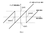
- the Doppler frequency fd becomes larger than the maximum frequency fdmax, that is, when the magnitude of the phase difference ⁇ becomes larger than 180 °, the relative speed Vd is turned back.
- the true relative speed Vr is expressed as shown in Expression (4).
- m is an integer including a negative value, and is a so-called Nyquist number.
- the measured relative speed Vd is referred to as a measured value Vd
- the true relative speed Vr is referred to as a relative speed Vr.
- the period ⁇ T when the period ⁇ T is as close to 0 as possible, no aliasing occurs and the relative speed Vr is always equal to the measured value Vd.
- the period ⁇ T has a certain width, for example, a width of several tens of ⁇ s. Therefore, in reality, aliasing occurs when the relative speed Vr increases. Therefore, it is necessary to correct the measured value Vd to the relative speed Vr. At this time, if the Nyquist number is not uniquely determined, the relative speed Vr is ambiguous. Therefore, the observation range Rg of the relative speed Vr is set.
- FIG. 5 shows the set observation range Rg.
- the relative speed Vr the target speed ⁇ the own vehicle speed Vs.
- the relative speed Vr is a positive value. It has become.
- the observation range Rg is limited according to the own vehicle speed Vs. Specifically, the observation range Rg is set so as to satisfy the following conditions (1) to (3). Further, in order to uniquely determine the Nyquist number, the observation range Rg is set to a range smaller than a width that is twice the Nyquist speed Vn.
- the observation range Rg is made narrower than a preset reference range.
- the speed threshold is set to a value about the slow speed of the vehicle, for example, 10 km / h.
- the reference range is an observation range Rg set with respect to the reference vehicle speed Vs, for example, 50 km / h, in a range smaller than a width that is twice the Nyquist speed Vn. Further, the observation range Rg may be narrowed as the host vehicle speed Vs decreases.
- the driving environment in which the host vehicle speed Vs is lower than the speed threshold is a parking lot, an intersection, or the like.
- a target existing around the host vehicle is a pedestrian having a small relative speed Vr. And slow vehicles. Therefore, when the host vehicle speed Vs is smaller than the speed threshold, there is no problem even if the observation range Rg is narrower than the reference range. By narrowing the observation range Rg, erroneous detection due to noise is reduced.
- Condition (2) The higher the vehicle speed Vs, the smaller the upper limit value of the observation range Rg.
- the host vehicle speed is 150 km / h even if there is another vehicle that overtakes the host vehicle at a relative speed Vr of 50 km / h.
- the host vehicle is traveling at the host vehicle speed Vs of 150 km / h, it is sufficient to observe up to a relative speed Vr of about 20 km / h. Therefore, there is no problem even if the upper limit value of the observation range Rg is reduced as the host vehicle speed Vs increases.
- a relative speed Vr equal to a negative value of the host vehicle speed Vs is entered.
- a target having a relative speed Vr equal to a negative value of the host vehicle speed Vs is a stationary object.
- the relative speed Vr of the stationary object is indicated by a broken line.
- a stationary object is often observed in any driving environment. Therefore, if the relative speed Vr of the stationary object turns back and is recognized as a moving object having a speed, there is a possibility that the stationary object is erroneously tracked. Therefore, the observation range Rg is set to a range in which the relative speed Vr of the stationary object does not return, so that the stationary object is not erroneously recognized as a moving object.
- a map of the observation range Rg with respect to the vehicle speed Vs as shown in FIG. 5 is created in advance and stored in a storage device such as a ROM.
- the map may be created up to the assumed maximum speed of the host vehicle speed Vs, for example, 200 km / h.
- the coherent integration time Ti is preferably set to a value smaller than 10 ms.
- c is the speed of light
- ⁇ F is the amount of change in the transmission frequency during the coherent integration time Ti.
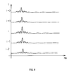
- the frequency spectra for each pulse calculated in S30 are arranged in time series, and FFT processing is performed for each predetermined distance width on the frequency spectra arranged in time series.
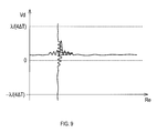
- the frequency spectrum with respect to the distance Re and the measured value Vd is calculated.
- FIG. 9 for the sake of convenience, it is represented by a two-dimensional plane, but is actually three-dimensional data.
- the distance Re and the measured value Vd are detected from the FFT processing result in S40.
- This measured value Vd is detected as a value in the range of ⁇ Vn to Vn.
- a candidate value for the relative speed Vr is calculated from the measured value Vd detected in S50 and Equation (4). For example, assuming that the Nyquist number is ⁇ 5 to 5, a plurality of candidate values for the relative speed Vr are calculated.
- an observation range Rg corresponding to the own vehicle speed Vs detected in S20 is set with reference to a map of the observation range Rg with respect to the own vehicle speed Vs prepared in advance.
- a candidate value that falls within the observation range Rg set in S70 among the candidate values of the relative speed Vr calculated in S60 is selected as the relative speed Vr.
- the relative velocity Vr is uniquely selected from a plurality of candidate values. This process is complete
- S20 corresponds to the process executed by the function of the speed detection unit
- S30 to S60 correspond to the process executed by the function of the candidate detection unit
- S70 corresponds to the process executed by the function of the range setting unit
- S80 corresponds to the process executed by the function of the selection unit.
- the observation range Rg is set to a range corresponding to the host vehicle speed Vs and smaller than a width that is twice the Nyquist speed Vn, the observation range Rg is used as an observation target using one type of period ⁇ T An appropriate target relative velocity Vr can be uniquely detected.
- the two-stage FFT processing is performed on the IF signal received by the FMCW radar and the measurement value Vd and the distance Re are detected.
- the present disclosure is limited to this. is not. Any radar system that can detect the phase between pulses may be used.
- the frequency of the high-frequency signal forming the inside of each pulse of the transmission signal is modulated so as to decrease linearly, but may be modulated so as to increase linearly. Further, the frequency of the high frequency signal may not be modulated.
- the observation range Rg may not be set so as to satisfy all of the conditions (1) to (3).
- the observation range Rg may be designed so as to satisfy only one or two of the conditions (1) to (3).
- a plurality of functions of one constituent element in the above embodiment may be realized by a plurality of constituent elements, or a single function of one constituent element may be realized by a plurality of constituent elements. . Further, a plurality of functions possessed by a plurality of constituent elements may be realized by one constituent element, or one function realized by a plurality of constituent elements may be realized by one constituent element. Moreover, you may abbreviate
- at least a part of the configuration of the above embodiment may be added to or replaced with the configuration of the other embodiment.
- all the aspects included in the technical idea specified only by the wording described in the claim are embodiment of this indication.
Landscapes
- Engineering & Computer Science (AREA)
- Radar, Positioning & Navigation (AREA)
- Remote Sensing (AREA)
- Physics & Mathematics (AREA)
- Computer Networks & Wireless Communication (AREA)
- General Physics & Mathematics (AREA)
- Electromagnetism (AREA)
- Signal Processing (AREA)
- Radar Systems Or Details Thereof (AREA)
- Traffic Control Systems (AREA)
Abstract
速度検出装置(10)は、速度検出部(S20)と、候補検出部(S30~S60)と、範囲設定部(S70)と、選択部(S80)と、を備える。範囲設定部は、相対速度の観測範囲を、速度検出部により検出された車両速度に応じた範囲で、且つ、パルスの繰り返し周期に応じたナイキスト速度の2倍となる幅よりも小さい範囲に設定する。選択部は、候補検出部により検出された相対速度の候補のうち、範囲設定部により設定された観測範囲に入る候補を相対速度として選択する。
Description
本国際出願は、2016年5月18日に日本国特許庁に出願された日本国特許出願第2016-099849号に基づくものであって、その優先権の利益を主張するものであり、日本国特許出願第2016-099849号のすべての内容を参照により本国際出願に援用する。
本開示は、車載ドップラーレーダによる受信信号から、物標の相対速度を検出する速度検出装置に関する。
一般に、ドップラーレーダは、一定の幅のパルス状に変調され且つ一定の周期で繰り返された送信信号に基づくレーダ波を送信し、レーダ波を反射する物標からの反射波を受信する。例として、FMCW方式のドップラーレーダでは、送信信号と受信信号とを混合して、各パルスの位相情報を有する混合信号を生成することで、2つのパルスの位相差に対応する相対速度を検出することができる。ただし、位相差が±180°を超えると、相対速度の折り返しが生じて相対速度に曖昧さが生じる。180°の位相差に対応する相対速度は、ナイキスト速度と呼ばれる。
そこで、下記非特許文献1に記載されているように、同じパルスを2種類の周期で交互に送信することで、ナイキスト速度を拡大し、相対速度の曖昧さを低減する技術が用いられてきた。
David P. Jorgensen, Tom R. Shepherd, and Alan S. Goldstein, 2000:A Dual-Pulse Repetition Frequency Scheme for Mitigating Velocity Ambiguities of the NOAA P-3 Airborne Doppler Radar. J. Atmos. Oceanic Technol., 17, 585-594
二種類の繰り返し周期を用いる場合、繰り返し周期ごとにパルスを分けて処理しなければならない。そのため、発明者の詳細な検討の結果、一種類の繰り返し周期を用いる場合よりも、コヒーレント積分できる反射パルスの数が減り、コヒーレント積分によるS/N比の改善度合いが低下するという課題が見出された。
本開示の1つの局面は、1種類のパルス繰り返し周期を用いて、物標の相対速度を一意に検出することが可能な速度検出装置を提供できることが望ましい。
本開示の1つの局面は、一定の幅のパルス状に変調され且つ一定の周期で繰り返す送信信号に基づくレーダ波を送信し、レーダ波を反射した物標からの反射波を受信する車載レーダにより受信された受信信号から、車載レーダが搭載された車両に対する物標の相対速度を検出する速度検出装置であって、速度検出部と、候補検出部と、範囲設定部と、選択部と、を備える。速度検出部は、車両速度を検出する。候補検出部は、受信信号に含まれる複数のパルスの位相差に応じた相対速度の候補を検出する。範囲設定部は、相対速度の観測範囲を、速度検出部により検出された車両速度に応じた範囲で、且つ、パルスの繰り返し周期に応じたナイキスト速度の2倍となる幅よりも小さい範囲に設定する。選択部は、候補検出部により検出された相対速度の候補のうち、範囲設定部により設定された観測範囲に入る候補を相対速度として選択する。
本開示の1つの局面は、一定の幅のパルス状に変調され且つ一定の周期で繰り返す送信信号に基づくレーダ波を送信し、レーダ波を反射した物標からの反射波を受信する車載レーダにより受信された受信信号から、車載レーダが搭載された車両に対する物標の相対速度を検出する速度検出装置であって、速度検出部と、候補検出部と、範囲設定部と、選択部と、を備える。速度検出部は、車両速度を検出する。候補検出部は、受信信号に含まれる複数のパルスの位相差に応じた相対速度の候補を検出する。範囲設定部は、相対速度の観測範囲を、速度検出部により検出された車両速度に応じた範囲で、且つ、パルスの繰り返し周期に応じたナイキスト速度の2倍となる幅よりも小さい範囲に設定する。選択部は、候補検出部により検出された相対速度の候補のうち、範囲設定部により設定された観測範囲に入る候補を相対速度として選択する。
一般に、車両速度に応じて、どのような相対速度を持った物標を注意すべきかが決まるので、相対速度の観測範囲を車両速度に応じて限定しても、注意すべき物標の観測には支障がない。そして、相対速度の観測範囲を限定することで、観測範囲をナイキスト速度の2倍となる幅よりも小さい範囲に設定することができるため、検出した相対速度の候補から観測範囲に入る相対速度を一意に選択することができる。すなわち、1種類の繰り返し周波数を用いて、観測対象として適切な物標の相対速度を一意に検出することができる。
なお、請求の範囲に記載した括弧内の符号は、本開示の一つの態様として後述する実施形態に記載の具体的手段との対応関係を示すものであって、本開示の技術的範囲を限定するものではない。
以下、図面を参照しながら、本開示を実施するための例示的な実施形態を説明する。
<構成>
まず、図1を参照して、レーダ装置1の構成について説明する。レーダ装置1は、発振器11と、増幅器12と、分配器14と、送信アンテナ16と、受信アンテナ部20と、受信スイッチ21と、増幅器22と、ミキサ23と、フィルタ24と、A/D変換器25と、を備え、車両に搭載されたミリ波レーダである。
<構成>
まず、図1を参照して、レーダ装置1の構成について説明する。レーダ装置1は、発振器11と、増幅器12と、分配器14と、送信アンテナ16と、受信アンテナ部20と、受信スイッチ21と、増幅器22と、ミキサ23と、フィルタ24と、A/D変換器25と、を備え、車両に搭載されたミリ波レーダである。
発振器11は、処理装置10からの指令に従って、周波数fc、波長λcのミリ波帯の高周波信号が一定の幅のパルス状に変調され、且つ一定の繰り返し周期ΔTで繰り返される変調信号を生成する。各パルスはコヒーレントパルスであり、図2に示すように、各パルスを形成する高周波信号の周波数は、所定の帯域内で、一定の割合で直線的に減少するように変調されている。そのため、送信信号Ssと受信信号Srとの周波数の差分には、物標までの距離に応じた送信から受信までの時間による周波数の変化分と、ドップラーシフトによる周波数の変化分が含まれる。ただし、各パルスの幅は、周波数の減少傾きが十分に大きくなるような狭い幅になっており、物標までの距離に応じた周波数の変化分は、ドップラーシフトによる周波数の変化分に比べて十分に大きくなる。よって、単一パルス内でのドップラーシフトによる周波数の変化分は無視することができる。増幅器12は、発振器11が生成する変調信号を増幅する。分配器14は、増幅器12の出力を送信信号Ssとローカル信号Lとに電力分配する。送信アンテナ16は、送信信号Ssに応じたレーダ波を放射する。
受信アンテナ部20は、n個の受信アンテナを含み、各受信アンテナのビーム幅はいずれも、送信アンテナ16のビーム幅全体を含むように設定されている。各受信アンテナはそれぞれCH1~CHnに割り当てられている。なお、nは自然数である。受信スイッチ21は、受信アンテナ部20に含まれるn個の受信アンテナのいずれかを順次選択し、選択した受信アンテナからの受信信号Srを受信アンテナの後段に供給する。増幅器22は、受信スイッチ21から供給される受信信号Srを増幅する。
ミキサ23は、増幅器22により増幅された受信信号Srと、送信信号Ssと同じ信号であるローカル信号Lとを混合して、中間周波数信号(以下、IF信号)を生成する。ここでは、IF信号として、受信信号Srとローカル信号Lとの周波数の差分を周波数とする低周波側のIF信号と、受信信号Srとローカル信号Lとの周波数の和を周波数とする高周波側のIF信号が生成される。フィルタ24は、ローパスフィルタであり、ミキサ23が生成したIF信号のうち高周波側のIF信号を除去して、低周波側のIF信号を出力する。本実施形態では、低周波側のIF信号が混合信号に相当する。A/D変換器25は、フィルタ24から出力されたIF信号をサンプリングしてデジタルデータDaに変換する。
処理装置10は、マイクロコンピュータを備えているとともに、デジタルデータDaについて、高速フーリエ変換(以下、FFT)処理等を実行するためのDSP等の演算処理装置を備えている。処理装置10は、CPUがROM等の非遷移的実体的記録媒体に格納されているプログラムを実行することにより、速度検出部、候補検出部、範囲設定部、及び選択部の機能を実現する。これらの機能の一部又は全部は、論理回路やアナログ回路等を組み合わせたハードウェアを用いて実現してもよい。また、処理装置は、1つのマイクロコンピュータを備えていてよいし、複数のマイクロコンピュータを備えていてもよい。処理装置10は、発振器11の起動及び停止や、A/D変換器25によるサンプリングを制御する。また、処理装置10は、車速センサ50の測定値から自車速度Vsを検出し、検出した自車速度Vsを用いて、デジタルデータDaから物標の相対速度Vrを検出するとともに、自車両から物標までの距離、物標の方位等の物標情報を検出する。本実施形態では、処理装置10が車速検出装置に相当する。
<相対速度の折り返し>
次に、相対速度Vrの折り返しについて説明する。ここでは、パルスi-2~i+2から、相対速度Vrを算出する場合について説明する。
次に、相対速度Vrの折り返しについて説明する。ここでは、パルスi-2~i+2から、相対速度Vrを算出する場合について説明する。
レーダ装置1から距離Reにある物標で反射された反射波を受信した場合、受信信号の位相θは、送信信号の位相θ0から、4πRe/λcの分だけ変化する。よって、位相の時間変化は、次の式(1)のように表される。


<観測範囲の設定>
次に、観測範囲Rgの設定の仕方について説明する。図5に、設定した観測範囲Rgを示す。ここでは、相対速度Vr=物標の速度-自車速度Vsとしており、物標の速度が自車速度Vsと同じ向きで自車速度Vsよりも大きい場合に、相対速度Vrは
正の値となっている。通常、自車速度Vsに応じて、どのような相対速度Vrを持った物標を注意すべきかが決まるため、自車速度Vsに応じて、観測範囲Rgを限定する。詳しくは、次の(1)~(3)の条件を満たすように、観測範囲Rgを設定する。さらに、ナイキスト数を一意に決めるために、観測範囲Rgは、ナイキスト速度Vnの2倍となる幅よりも小さい範囲に設定する。
次に、観測範囲Rgの設定の仕方について説明する。図5に、設定した観測範囲Rgを示す。ここでは、相対速度Vr=物標の速度-自車速度Vsとしており、物標の速度が自車速度Vsと同じ向きで自車速度Vsよりも大きい場合に、相対速度Vrは
正の値となっている。通常、自車速度Vsに応じて、どのような相対速度Vrを持った物標を注意すべきかが決まるため、自車速度Vsに応じて、観測範囲Rgを限定する。詳しくは、次の(1)~(3)の条件を満たすように、観測範囲Rgを設定する。さらに、ナイキスト数を一意に決めるために、観測範囲Rgは、ナイキスト速度Vnの2倍となる幅よりも小さい範囲に設定する。
条件(1):自車速度Vsが予め設定された速度閾値よりも小さい場合は、観測範囲Rgを予め設定された基準範囲よりも狭くする。速度閾値は、車両の徐行速度程度の値、例えば10km/hに設定されている。また、基準範囲は、ナイキスト速度Vnの2倍となる幅よりも小さい範囲で、基準となる自車速度Vs、例えば50km/hに対して設定される観測範囲Rgである。また、自車速度Vsが小さいほど、観測範囲Rgが狭くなるようにしてもよい。
自車速度Vsが速度閾値よりも小さくなる走行環境は、駐車場や交差点等であり、このような走行環境において自車両の周囲に存在する物標は、相対速度Vrの大きさが小さい歩行者や徐行車両等である。そこで、自車速度Vsが速度閾値よりも小さい場合は、観測範囲Rgを基準範囲よりも狭くしても支障がない。観測範囲Rgを狭くすることで、ノイズによる誤検出が低減される。
条件(2):自車速度Vsが大きいほど、観測範囲Rgの上限値を小さくする。自車速度Vsが大きいほど、自車両を追い越す他車両の相対速度Vrは小さくなる。例えば、自車両が50km/hの自車速度Vsで走行中の場合に、50km/hの相対速度Vrで自車両を追い抜く他車両は存在しても、自車両が150km/hの自車速度Vsで走行中の場合に、50km/hの相対速度Vrで追い抜く他車両は存在しないと考えられる。自車両が150km/hの自車速度Vsで走行中の場合は、20km/h程度の相対速度Vrまで観測できれば十分である。よって、自車速度Vsが大きいほど、観測範囲Rgの上限値を小さくしても支障がない。
条件(3):自車速度Vsを負にした値に等しい相対速度Vrが入るようにする。自車速度Vsを負にした値に等しい相対速度Vrを持つ物標は静止物である。図5では、静止物の相対速度Vrを破線で示している。どのような走行環境でも静止物は観測されることが多い。そのため、静止物の相対速度Vrが折り返して、速度を有する移動物として認識されると、誤って静止物をトラッキングするおそれがある。よって、観測範囲Rgを、静止物の相対速度Vrが折り返さない範囲に設定して、静止物を移動物と誤認識されないようにする。
本実施形態では、図5に示すような、自車速度Vsに対する観測範囲Rgのマップを予め作成して、ROM等の記憶装置に記憶しておく。マップは、自車速度Vsの想定される最高速度、例えば200km/hまで作成しておけばよい。
<相対速度検出>
次に、物標の相対速度Vrを検出する処理手順について、図6のフローチャートを参照して説明する。本処理手順は、IF信号が検出される都度、処理装置10が実行する。
次に、物標の相対速度Vrを検出する処理手順について、図6のフローチャートを参照して説明する。本処理手順は、IF信号が検出される都度、処理装置10が実行する。
まず、S10では、IF信号をサンプリングしたデジタルデータDaを取得する。
続いて、S20では、車速センサ50の測定値から自車速度Vsを検出する。
続いて、S30では、S10で取得したデジタルデータDaをコヒーレント積分する。コヒーレント積分するパルス数をNiとすると、コヒーレント積分時間Tiは、Ti=NiΔTとなる。コヒーレント積分時間Tiは、物標が変動していないと見なせる時間であり、レーダの距離分解能ΔR=c/ΔFよりも十分に小さい必要がある。例えば、ΔFを300MHz、物標の相対速度Vrを50m/sとした場合、コヒーレント積分時間Tiは10msよりも小さい値にすることが望ましい。なお、cは光速であり、ΔFは、コヒーレント積分時間Tiにおける送信周波数の周波数変化量である。まず、図7に示すように、パルスごとに周波数解析、具体的にはFFT処理を行う。これにより、パルスごとに、距離Reに対する周波数スペクトルが算出される。
続いて、S20では、車速センサ50の測定値から自車速度Vsを検出する。
続いて、S30では、S10で取得したデジタルデータDaをコヒーレント積分する。コヒーレント積分するパルス数をNiとすると、コヒーレント積分時間Tiは、Ti=NiΔTとなる。コヒーレント積分時間Tiは、物標が変動していないと見なせる時間であり、レーダの距離分解能ΔR=c/ΔFよりも十分に小さい必要がある。例えば、ΔFを300MHz、物標の相対速度Vrを50m/sとした場合、コヒーレント積分時間Tiは10msよりも小さい値にすることが望ましい。なお、cは光速であり、ΔFは、コヒーレント積分時間Tiにおける送信周波数の周波数変化量である。まず、図7に示すように、パルスごとに周波数解析、具体的にはFFT処理を行う。これにより、パルスごとに、距離Reに対する周波数スペクトルが算出される。
続いて、S40では、図8に示すように、S30で算出したパルスごとの周波数スペクトルを時系列に並べ、時系列に並べた周波数スペクトルに対して、所定の距離幅ごとにFFT処理を行う。これにより、図9に示すように、距離Re及び測定値Vdに対する周波数スペクトルが算出される。図9では、便宜上2次元平面で表しているが、実際には3次元データとなる。
続いて、S50では、S40のFFT処理結果から、距離Re及び測定値Vdを検出する。この測定値Vdは、-Vn~Vnの範囲の値として検出される。
続いて、S60では、S50で検出した測定値Vdと式(4)とから、相対速度Vrの候補値を算出する。例えば、ナイキスト数を-5~5として、相対速度Vrの候補値を複数算出する。
続いて、S60では、S50で検出した測定値Vdと式(4)とから、相対速度Vrの候補値を算出する。例えば、ナイキスト数を-5~5として、相対速度Vrの候補値を複数算出する。
続いて、S70では、予め作成されている自車速度Vsに対する観測範囲Rgのマップを参照して、S20で検出した自車速度Vsに応じた観測範囲Rgを設定する。
続いて、S80では、S60で算出した相対速度Vrの候補値のうち、S70で設定した観測範囲Rgに入る候補値を、相対速度Vrとして選択する。上述したように、観測範囲Rgは、ナイキスト速度Vnの2倍の幅よりも小さい範囲に設定されるため、複数の候補値の中から、相対速度Vrが一意に選択される。以上で、本処理を終了する。
続いて、S80では、S60で算出した相対速度Vrの候補値のうち、S70で設定した観測範囲Rgに入る候補値を、相対速度Vrとして選択する。上述したように、観測範囲Rgは、ナイキスト速度Vnの2倍の幅よりも小さい範囲に設定されるため、複数の候補値の中から、相対速度Vrが一意に選択される。以上で、本処理を終了する。
なお、物標の方位推定については説明を省略したが、MUSIC等の周知の手法により、物標の方位も推定することができる。また、本実施形態では、S20が、速度検出部の機能が実行する処理に相当し、S30~S60が、候補検出部の機能が実行する処理に相当する。また、S70が、範囲設定部の機能が実行する処理に相当し、S80が、選択部の機能が実行する処理に相当する。
<効果>
以上説明した本実施形態によれば、以下の効果が得られる。
(1)観測範囲Rgを、自車速度Vsに応じた範囲で、且つナイキスト速度Vnの2倍となる幅よりも小さい範囲に設定したことにより、1種類の周期ΔTを用いて、観測対象として適切な物標の相対速度Vrを一意に検出することができる。
以上説明した本実施形態によれば、以下の効果が得られる。
(1)観測範囲Rgを、自車速度Vsに応じた範囲で、且つナイキスト速度Vnの2倍となる幅よりも小さい範囲に設定したことにより、1種類の周期ΔTを用いて、観測対象として適切な物標の相対速度Vrを一意に検出することができる。
(2)自車速度Vsが小さい場合には、観測範囲Rgを狭くすることにより、ノイズによる誤検出を低減して、相対速度Vrの検出精度を向上させることができる。
(3)自車速度Vsが大きいほど、観測範囲Rgの上限値を小さくすることで、観測対象として不適切な物標を観測範囲Rgから除外し、観測範囲Rgを効率的に設定することができる。特に、自車速度Vsが大きいほど、静止物の相対速度Vrの大きさが大きくなるため観測範囲Rgの下限値を小さくしなければならないが、上限値を小さくすることで、相対速度Vrが一意に決まる範囲内に下限値を収めることができる。
(3)自車速度Vsが大きいほど、観測範囲Rgの上限値を小さくすることで、観測対象として不適切な物標を観測範囲Rgから除外し、観測範囲Rgを効率的に設定することができる。特に、自車速度Vsが大きいほど、静止物の相対速度Vrの大きさが大きくなるため観測範囲Rgの下限値を小さくしなければならないが、上限値を小さくすることで、相対速度Vrが一意に決まる範囲内に下限値を収めることができる。
(4)観測範囲Rgを、自車速度Vsを負にした値に等しい相対速度Vrが入るように設定したことにより、静止物を移動物と誤認識してトラッキングすることを防止または抑制することができる。
(他の実施形態)
以上、本開示を実施するための形態について説明したが、本開示は上述の実施形態に限定されることなく、種々変形して実施することができる。
以上、本開示を実施するための形態について説明したが、本開示は上述の実施形態に限定されることなく、種々変形して実施することができる。
(a)上記実施形態では、FMCW方式のレーダで受信されるIF信号に対して2段階のFFT処理を行って、測定値Vdと距離Reを検出したが、本開示はこれに限定されるものではない。パルス間の位相を検出できるレーダ方式であればどのような方式を用いてもよい。
(b)上記実施形態では、送信信号の各パルス内を形成する高周波信号の周波数を、直線的に減少するように変調したが、直線的に増加するように変調してもよい。また、高周波信号の周波数は変調しなくてもよい。
(c)観測範囲Rgは、条件(1)~(3)の全てを満たすように設定しなくてもよい。観測範囲Rgは、条件(1)~(3)のうちの1つのみ又は2つのみを満たすように設計してもよい。
(d)自車速度Vsに対する観測範囲Rgのマップを記憶しておく代わりに、自車速度Vsに対する観測範囲Rgの関係式を記憶しておき、検出した自車速度Vsと関係式とから、自車速度Vsに応じた観測範囲Rgを設定してもよい。
(e)上記実施形態における1つの構成要素が有する複数の機能を、複数の構成要素によって実現したり、1つの構成要素が有する1つの機能を、複数の構成要素によって実現したりしてもよい。また、複数の構成要素が有する複数の機能を、1つの構成要素によって実現したり、複数の構成要素によって実現される1つの機能を、1つの構成要素によって実現したりしてもよい。また、上記実施形態の構成の一部を省略してもよい。また、上記実施形態の構成の少なくとも一部を、他の上記実施形態の構成に対して付加又は置換してもよい。なお、請求の範囲に記載した文言のみによって特定される技術思想に含まれるあらゆる態様が本開示の実施形態である。
(f)上述した速度検出装置の他、当該速度検出装置を構成要素とするシステム、当該速度検出装置としてコンピュータを機能させるためのプログラム、このプログラムを記録した半導体メモリ等の非遷移的実態的記録媒体、速度検出方法など、種々の形態で本開示を実現することもできる。
Claims (4)
- 一定の幅のパルス状に変調され且つ一定の周期で繰り返す送信信号に基づくレーダ波を送信し、前記レーダ波を反射した物標からの反射波を受信する車載レーダ(1)により受信された受信信号から、前記車載レーダが搭載された車両に対する前記物標の相対速度を検出する速度検出装置(10)であって、
前記車両の車両速度を検出するように構成された速度検出部(S20)と、
前記受信信号に含まれる複数のパルスの位相差に応じた前記相対速度の候補を検出するように構成された候補検出部(S30~S60)と、
前記相対速度の観測範囲を、前記速度検出部により検出された前記車両速度に応じた範囲で、且つ、前記パルスの繰り返し周期に応じたナイキスト速度の2倍となる幅よりも小さい範囲に設定するように構成された範囲設定部(S70)と、
前記候補検出部により検出された前記相対速度の候補のうち、前記範囲設定部により設定された前記観測範囲に入る候補を前記相対速度として選択するように構成された選択部(S80)と、を備える、速度検出装置。 - 前記範囲設定部は、前記速度検出部により検出された前記車両速度が予め設定された速度閾値よりも小さい場合は、前記観測範囲を予め設定された基準範囲よりも狭くなるように、または、前記車両速度が小さいほど、前記観測範囲が狭くなるように、設定するように構成された、請求項1に記載の速度検出装置。
- 前記範囲設定部は、前記速度検出部により検出された前記車両速度が大きいほど、前記観測範囲の上限値を小さく設定するように構成された、請求項1又は2に記載の速度検出装置。
- 前記範囲設定部は、前記観測範囲を、前記自車速度を負にした値に等しい前記相対速度が入るように設定するように構成された、請求項1~3のいずれか1項に記載の速度検出装置。
Priority Applications (3)
| Application Number | Priority Date | Filing Date | Title |
|---|---|---|---|
| US16/302,256 US10871557B2 (en) | 2016-05-18 | 2017-05-18 | Velocity detection apparatus |
| DE112017002559.1T DE112017002559T5 (de) | 2016-05-18 | 2017-05-18 | Geschwindigkeitserfassungsvorrichtung |
| CN201780030467.2A CN109154652B (zh) | 2016-05-18 | 2017-05-18 | 速度检测装置 |
Applications Claiming Priority (2)
| Application Number | Priority Date | Filing Date | Title |
|---|---|---|---|
| JP2016-099849 | 2016-05-18 | ||
| JP2016099849A JP6500838B2 (ja) | 2016-05-18 | 2016-05-18 | 速度検出装置 |
Publications (1)
| Publication Number | Publication Date |
|---|---|
| WO2017200041A1 true WO2017200041A1 (ja) | 2017-11-23 |
Family
ID=60325948
Family Applications (1)
| Application Number | Title | Priority Date | Filing Date |
|---|---|---|---|
| PCT/JP2017/018666 Ceased WO2017200041A1 (ja) | 2016-05-18 | 2017-05-18 | 速度検出装置 |
Country Status (5)
| Country | Link |
|---|---|
| US (1) | US10871557B2 (ja) |
| JP (1) | JP6500838B2 (ja) |
| CN (1) | CN109154652B (ja) |
| DE (1) | DE112017002559T5 (ja) |
| WO (1) | WO2017200041A1 (ja) |
Families Citing this family (12)
| Publication number | Priority date | Publication date | Assignee | Title |
|---|---|---|---|---|
| JP6494712B2 (ja) * | 2017-09-05 | 2019-04-03 | 三菱電機株式会社 | レーダ装置 |
| JP2020030140A (ja) * | 2018-08-23 | 2020-02-27 | 株式会社デンソーテン | 物標検出装置および物標検出方法 |
| JP2020139776A (ja) * | 2019-02-27 | 2020-09-03 | 沖電気工業株式会社 | Fmcw方式レーダ装置 |
| JP7116000B2 (ja) * | 2019-03-15 | 2022-08-09 | 株式会社Soken | 物体追跡装置 |
| EP3951429A4 (en) * | 2019-03-28 | 2022-06-01 | Sony Semiconductor Solutions Corporation | SIGNAL PROCESSING DEVICE, SIGNAL PROCESSING METHOD, PROGRAM AND INFORMATION PROCESSING DEVICE |
| CN112444803B (zh) * | 2019-08-29 | 2024-02-27 | 比亚迪股份有限公司 | 车载雷达的目标检测方法和检测装置、车辆 |
| CN112444802B (zh) * | 2019-08-29 | 2024-06-18 | 比亚迪股份有限公司 | 车载雷达的目标检测方法和检测装置、车辆 |
| US11592548B2 (en) * | 2019-09-27 | 2023-02-28 | Intel Corporation | Methods and apparatus to improve doppler velocity estimation |
| JP7351706B2 (ja) * | 2019-10-15 | 2023-09-27 | 株式会社Soken | 物体追跡装置 |
| JP2022091352A (ja) * | 2020-12-09 | 2022-06-21 | 古河電気工業株式会社 | レーダー処理装置及びレーダー処理方法 |
| JP7620488B2 (ja) * | 2021-04-23 | 2025-01-23 | Jrcモビリティ株式会社 | Fmcwレーダ信号処理装置及びfmcwレーダ信号処理プログラム |
| CN115980736A (zh) * | 2022-12-15 | 2023-04-18 | 成都晨电智能科技有限公司 | Fmcw雷达扩展测速方法、测速系统及车尾警示装置 |
Citations (6)
| Publication number | Priority date | Publication date | Assignee | Title |
|---|---|---|---|---|
| JPH06242234A (ja) * | 1993-02-19 | 1994-09-02 | Nissan Motor Co Ltd | 車両近接警報装置 |
| JP2005173806A (ja) * | 2003-12-09 | 2005-06-30 | Nissan Motor Co Ltd | 先行車両検出装置、自車両制御装置及び先行車両検出方法 |
| WO2011007828A1 (ja) * | 2009-07-16 | 2011-01-20 | 国立大学法人 千葉大学 | Fm-cwレーダ装置、ドップラ速度測定方法 |
| JP2011149871A (ja) * | 2010-01-22 | 2011-08-04 | Toshiba Corp | 周波数検出器、この周波数検出器を備える合成帯域レーダ、及び飛翔体誘導装置 |
| JP2016003873A (ja) * | 2014-06-13 | 2016-01-12 | 株式会社デンソー | レーダ装置 |
| JP2016075524A (ja) * | 2014-10-03 | 2016-05-12 | 株式会社デンソー | レーダ装置 |
Family Cites Families (11)
| Publication number | Priority date | Publication date | Assignee | Title |
|---|---|---|---|---|
| US5027122A (en) * | 1990-03-12 | 1991-06-25 | Raytheon Company | Method and apparatus for doppler velocity de-aliasing |
| US7053813B1 (en) * | 2004-04-22 | 2006-05-30 | University Corporation For Atmospheric Research | Radar system |
| FR2886737B1 (fr) * | 2005-06-02 | 2007-09-07 | Meteo France Etablissement Pub | Procede de mesure de la vitesse de l'air par radar doppler |
| US7504989B2 (en) * | 2006-08-09 | 2009-03-17 | Fujitsu Ten Limited | On-vehicle radar device |
| US7605744B1 (en) * | 2008-06-03 | 2009-10-20 | Vaisala Oyj | Method for extension of unambiguous range and velocity of a weather radar |
| DE102009057191A1 (de) * | 2009-12-05 | 2011-06-09 | Valeo Schalter Und Sensoren Gmbh | Verfahren zum eindeutigen Bestimmen einer Entfernung und/oder einer relativen Geschwindigkeit eines Objektes, Fahrerassistenzeinrichtung und Kraftfahrzeug |
| JP5811804B2 (ja) * | 2011-11-24 | 2015-11-11 | トヨタ自動車株式会社 | 車両用周辺監視装置 |
| JP6075846B2 (ja) * | 2012-10-30 | 2017-02-08 | 古野電気株式会社 | レーダ装置、及び速度算出方法 |
| JP6369035B2 (ja) * | 2013-02-05 | 2018-08-08 | 株式会社デンソー | 物標検出装置 |
| US20150070207A1 (en) * | 2013-09-06 | 2015-03-12 | Valeo Radar Systems, Inc. | Method and Apparatus For Self Calibration of A Vehicle Radar System |
| JP6511253B2 (ja) | 2014-11-25 | 2019-05-15 | 日本光電工業株式会社 | 生体情報表示装置 |
-
2016
- 2016-05-18 JP JP2016099849A patent/JP6500838B2/ja active Active
-
2017
- 2017-05-18 DE DE112017002559.1T patent/DE112017002559T5/de active Pending
- 2017-05-18 CN CN201780030467.2A patent/CN109154652B/zh active Active
- 2017-05-18 US US16/302,256 patent/US10871557B2/en active Active
- 2017-05-18 WO PCT/JP2017/018666 patent/WO2017200041A1/ja not_active Ceased
Patent Citations (6)
| Publication number | Priority date | Publication date | Assignee | Title |
|---|---|---|---|---|
| JPH06242234A (ja) * | 1993-02-19 | 1994-09-02 | Nissan Motor Co Ltd | 車両近接警報装置 |
| JP2005173806A (ja) * | 2003-12-09 | 2005-06-30 | Nissan Motor Co Ltd | 先行車両検出装置、自車両制御装置及び先行車両検出方法 |
| WO2011007828A1 (ja) * | 2009-07-16 | 2011-01-20 | 国立大学法人 千葉大学 | Fm-cwレーダ装置、ドップラ速度測定方法 |
| JP2011149871A (ja) * | 2010-01-22 | 2011-08-04 | Toshiba Corp | 周波数検出器、この周波数検出器を備える合成帯域レーダ、及び飛翔体誘導装置 |
| JP2016003873A (ja) * | 2014-06-13 | 2016-01-12 | 株式会社デンソー | レーダ装置 |
| JP2016075524A (ja) * | 2014-10-03 | 2016-05-12 | 株式会社デンソー | レーダ装置 |
Also Published As
| Publication number | Publication date |
|---|---|
| CN109154652B (zh) | 2022-12-13 |
| US20190120953A1 (en) | 2019-04-25 |
| US10871557B2 (en) | 2020-12-22 |
| JP2017207368A (ja) | 2017-11-24 |
| CN109154652A (zh) | 2019-01-04 |
| JP6500838B2 (ja) | 2019-04-17 |
| DE112017002559T5 (de) | 2019-02-21 |
Similar Documents
| Publication | Publication Date | Title |
|---|---|---|
| JP6500838B2 (ja) | 速度検出装置 | |
| EP3124994B1 (en) | Vehicle radar device | |
| US20200150260A1 (en) | Multiple input multiple output (mimo) frequency-modulated continuous-wave (fmcw) radar system | |
| US9354304B2 (en) | Method for cyclically measuring distances and velocities of objects using an FMCW radar sensor | |
| JP4724694B2 (ja) | 電波レーダ装置 | |
| JP6716984B2 (ja) | 物標検出装置 | |
| CN115087884B (zh) | 雷达装置、观测对象检测方法以及车载装置 | |
| JP2018059813A (ja) | レーダ装置および物標検出方法 | |
| JP2012510055A (ja) | レーダー信号処理方法およびレーダー信号処理装置 | |
| JP2015514971A (ja) | 物標検出の方法 | |
| JP3664671B2 (ja) | ミリ波レーダ装置 | |
| CN106662644B (zh) | 用于检测至少一个对象相对于接收信号的接收器的速度和距离的方法及装置 | |
| US8884814B2 (en) | Processing method for FMCW radar signal with dual pulse repetition frequency | |
| JPWO2019049680A1 (ja) | レーダ装置およびそれを備える自動車 | |
| JP2019045365A (ja) | レーダ装置 | |
| JP7261302B2 (ja) | レーダ装置 | |
| CN102147461B (zh) | 观测信号处理装置 | |
| CN115616562A (zh) | 使用雷达检测目标的装置和方法 | |
| JP7160561B2 (ja) | 方位演算装置及び方位演算方法 | |
| US12560704B2 (en) | Apparatus and method with radar | |
| JP6779415B2 (ja) | レーダ装置および目標距離算出方法 | |
| US12529776B2 (en) | Vehicle radar system | |
| WO2020054031A1 (ja) | レーダ装置および目標距離計測方法 | |
| JP2017167839A (ja) | 車載装置 | |
| CN112771402A (zh) | 用于在雷达系统中进行检测的方法 |
Legal Events
| Date | Code | Title | Description |
|---|---|---|---|
| 121 | Ep: the epo has been informed by wipo that ep was designated in this application |
Ref document number: 17799465 Country of ref document: EP Kind code of ref document: A1 |
|
| 122 | Ep: pct application non-entry in european phase |
Ref document number: 17799465 Country of ref document: EP Kind code of ref document: A1 |