WO2017199874A1 - 弾性体、及びその製造方法 - Google Patents
弾性体、及びその製造方法 Download PDFInfo
- Publication number
- WO2017199874A1 WO2017199874A1 PCT/JP2017/018029 JP2017018029W WO2017199874A1 WO 2017199874 A1 WO2017199874 A1 WO 2017199874A1 JP 2017018029 W JP2017018029 W JP 2017018029W WO 2017199874 A1 WO2017199874 A1 WO 2017199874A1
- Authority
- WO
- WIPO (PCT)
- Prior art keywords
- elastic body
- molding
- tape
- polyurethane
- molding groove
- Prior art date
- Legal status (The legal status is an assumption and is not a legal conclusion. Google has not performed a legal analysis and makes no representation as to the accuracy of the status listed.)
- Ceased
Links
Images


Classifications
-
- B—PERFORMING OPERATIONS; TRANSPORTING
- B29—WORKING OF PLASTICS; WORKING OF SUBSTANCES IN A PLASTIC STATE IN GENERAL
- B29C—SHAPING OR JOINING OF PLASTICS; SHAPING OF MATERIAL IN A PLASTIC STATE, NOT OTHERWISE PROVIDED FOR; AFTER-TREATMENT OF THE SHAPED PRODUCTS, e.g. REPAIRING
- B29C41/00—Shaping by coating a mould, core or other substrate, i.e. by depositing material and stripping-off the shaped article; Apparatus therefor
- B29C41/24—Shaping by coating a mould, core or other substrate, i.e. by depositing material and stripping-off the shaped article; Apparatus therefor for making articles of indefinite length
- B29C41/30—Shaping by coating a mould, core or other substrate, i.e. by depositing material and stripping-off the shaped article; Apparatus therefor for making articles of indefinite length incorporating preformed parts or layers, e.g. moulding around inserts or for coating articles
-
- B—PERFORMING OPERATIONS; TRANSPORTING
- B29—WORKING OF PLASTICS; WORKING OF SUBSTANCES IN A PLASTIC STATE IN GENERAL
- B29C—SHAPING OR JOINING OF PLASTICS; SHAPING OF MATERIAL IN A PLASTIC STATE, NOT OTHERWISE PROVIDED FOR; AFTER-TREATMENT OF THE SHAPED PRODUCTS, e.g. REPAIRING
- B29C41/00—Shaping by coating a mould, core or other substrate, i.e. by depositing material and stripping-off the shaped article; Apparatus therefor
- B29C41/34—Component parts, details or accessories; Auxiliary operations
- B29C41/36—Feeding the material on to the mould, core or other substrate
-
- B—PERFORMING OPERATIONS; TRANSPORTING
- B32—LAYERED PRODUCTS
- B32B—LAYERED PRODUCTS, i.e. PRODUCTS BUILT-UP OF STRATA OF FLAT OR NON-FLAT, e.g. CELLULAR OR HONEYCOMB, FORM
- B32B3/00—Layered products comprising a layer with external or internal discontinuities or unevennesses, or a layer of non-planar shape; Layered products comprising a layer having particular features of form
- B32B3/02—Layered products comprising a layer with external or internal discontinuities or unevennesses, or a layer of non-planar shape; Layered products comprising a layer having particular features of form characterised by features of form at particular places, e.g. in edge regions
-
- G—PHYSICS
- G03—PHOTOGRAPHY; CINEMATOGRAPHY; ANALOGOUS TECHNIQUES USING WAVES OTHER THAN OPTICAL WAVES; ELECTROGRAPHY; HOLOGRAPHY
- G03G—ELECTROGRAPHY; ELECTROPHOTOGRAPHY; MAGNETOGRAPHY
- G03G15/00—Apparatus for electrographic processes using a charge pattern
-
- G—PHYSICS
- G03—PHOTOGRAPHY; CINEMATOGRAPHY; ANALOGOUS TECHNIQUES USING WAVES OTHER THAN OPTICAL WAVES; ELECTROGRAPHY; HOLOGRAPHY
- G03G—ELECTROGRAPHY; ELECTROPHOTOGRAPHY; MAGNETOGRAPHY
- G03G21/00—Arrangements not provided for by groups G03G13/00 - G03G19/00, e.g. cleaning, elimination of residual charge
Definitions
- the present invention relates to an elastic body used for a blade of an electrophotographic apparatus such as a copying machine, a printer, a facsimile machine, or a multifunction machine of these.
- various blades such as a cleaning blade that scrapes off excess toner and a developing blade that uniformizes the thickness of toner in the developing unit are used.
- the blade is composed of an elastic body and a support member.
- thermosetting polyurethane having appropriate hardness and elasticity is used as the elastic body.
- the life of each member has been increasing in an electrophotographic apparatus, and the elastic body is required to have improved wear resistance.
- the elastic body is also required to contribute to a long life of the entire system, such as prevention of filming (adhesion) of toner and external additives to the photosensitive drum and reduction of wear of the photosensitive drum.
- the elastic body is required to have a low coefficient of friction.
- Patent Document 1 discloses that the edge portion and the base portion (backup portion) are formed of polyurethanes having different materials, and only the edge portion is high. An elastic body having hardness has been proposed.
- Patent Document 2 discloses an elastic material in which only an image bearing member contact portion (edge portion) of an elastic body made of a single polyurethane is impregnated with an isocyanate compound, and only the contact portion with the image bearing member is hardened. The body has been proposed. However, the elastic bodies proposed in Patent Documents 1 and 2 have a limit in increasing the hardness because polyurethane is used for the edge portion.
- An object of the present invention is to provide a blade having a low friction coefficient at an edge portion.
- the tape-shaped substrate is made of any one of ultra high molecular weight polyethylene, fluororesin, polyether ether ketone, polyimide, polyphenylene sulfide, and polyethylene terephthalate. Or 2.
- the molding groove is covered with an endless belt that rotates in synchronization with the rotation of the molding drum while the molding drum is rotated, and the polyurethane composition is cured in a cavity formed by the molding groove and the endless belt.
- manufacturing the belt-like elastic body Cutting the strip elastic body; A method for producing an elastic body having an edge portion made of a tape-like base material and a backup portion made of polyurethane. 6).
- the molding groove is covered with an endless belt that rotates in synchronization with the rotation of the molding drum while the molding drum is rotated, and the polyurethane composition is cured in a cavity formed by the molding groove and the endless belt.
- manufacturing the belt-like elastic body Cutting the strip elastic body;
- the elastic body which has the edge part which consists of a tape-shaped base material manufactured by the manufacturing method which has these, and the backup part which consists of polyurethane.
- the edge portion is made of a tape-like substrate, and the friction coefficient of the edge portion can be set to a low value that cannot be achieved with polyurethane.
- the backup portion is made of conventionally used polyurethane. Therefore, the elastic body of the present invention is highly reliable and has excellent cleaning properties while being in contact with the photoreceptor at a pressure equivalent to that of a conventional elastic body. Since the elastic body of the present invention has a low coefficient of friction at the edge portion, it can be suitably used for low-melting-point toners and fine toners that have been used in recent years.
- the elastic body of the present invention has a longer life compared to a conventional elastic body, and can further extend the life of the photoconductor in contact with the elastic body.
- the tape-shaped substrate having a thickness of 3 ⁇ m or more and 500 ⁇ m or less has sufficient flexibility and can follow the deformation of the backup part, and thus is difficult to peel off from the backup part. Moreover, it is excellent also in the handleability at the time of manufacture. Further, the wear resistance can be further improved by using any one of ultra high molecular weight polyethylene, fluororesin, polyether ether ketone, polyimide, polyphenylene sulfide, and polyethylene terephthalate as the tape-like substrate.
- the elastic body of the present invention can be continuously manufactured by using a forming drum having a forming groove on the outer periphery, and is excellent in productivity.
- Schematic view from above of the forming drum during elastic body manufacturing The figure which shows a mode that a sheet-like elastic body is cut
- FIG. 1 shows a structural example of the elastic body of the present invention.
- the elastic body 1 which is one structural example includes an edge portion 11 made of a tape-like substrate and a backup portion 12 made of polyurethane.
- the edge part 11 consists of a tape-shaped base material, and has higher hardness and lower friction than polyurethane.
- the backup part 12 consists of polyurethane, and has moderate elasticity as an elastic body.
- the width of the elastic body of the present invention is about 5 mm to 20 mm, and the thickness is about 1 mm to 3 mm.
- the length of the elastic body is appropriately selected according to the width of the photosensitive drum to be contacted, that is, the width of the paper to be printed, but is about 220 mm when A4 size paper is used. Moreover, it is preferable that an edge part and a backup part have a different color so that it can distinguish at a glance.
- the edge portion 11 is made of a tape-like base material, is provided along one side in the length direction of the elastic body 1, and constitutes one corner in the cross section in the thickness direction of the elastic body 1.
- the elastic body 1 is in contact with the photosensitive drum at a side or surface formed by the edge portion 11.
- the edge portion can be provided on the entire width direction of the elastic body.
- the tape-shaped substrate constituting the edge portion is not particularly limited as long as it has a lower friction coefficient than polyurethane.
- ultrahigh molecular weight polyethylene UHMWPE
- polytetrafluoroethylene PTFE
- tetrafluoroethylene Fluororesin such as perfluoroalkyl vinyl ether copolymer (PFA), tetrafluoroethylene / hexafluoropropylene copolymer (FEP), tetrafluoroethylene / ethylene copolymer (ETFE), polyacetal resin (POM), polyamide resin ( PA, polyimide (PI), polyether ether ketone (PEEK), polyphenylene sulfide (PPS), polyethylene terephthalate (PET), polycarbonate (PC) and the like can be suitably used.
- UHMWPE ultrahigh molecular weight polyethylene
- PTFE polytetrafluoroethylene
- Fluororesin such as perfluoroalkyl vinyl
- ultra high molecular weight polyethylene polytetrafluoroethylene, tetrafluoroethylene / perfluoroalkyl vinyl ether copolymer, tetrafluoroethylene / hexafluoropropylene copolymer, tetrafluoroethylene / ethylene copolymer, which are particularly excellent in wear resistance.
- Fluorine resins such as polymers, polyether ether ketone, polyimide, polyphenylene sulfide, and polyethylene terephthalate are preferable.
- the ultra-high molecular weight polyethylene is a polyethylene having a weight average molecular weight increased to 1 million or more, and is commercially available, for example, under the trade names Dyneema (Ran DSM) and Spectra (Honeywell).
- the thickness of the tape-shaped substrate is preferably thin, preferably 500 ⁇ m or less, more preferably 300 ⁇ m or less, further preferably 100 ⁇ m or less, and most preferably 50 ⁇ m or less.
- the lower limit of the thickness of the tape-shaped substrate is not particularly limited, but it may be 3 ⁇ m or more from the viewpoint of handleability during production.
- the thickness of the tape-like substrate with respect to the thickness of the entire elastic body is preferably 50% or less, and preferably 30% or less. More preferably, it is 10% or less, more preferably 5% or less.
- the width of the tape-shaped substrate is not particularly limited, but generally, the narrower the width, the cheaper the width, and the narrower the width, the better.
- the width of the tape-shaped substrate is preferably 2 mm or more from the viewpoint of handleability during production.
- the edge part of an elastic body consists of a tape-shaped base material, the thickness and width
- the tape-like base material is preferably subjected to a surface treatment for improving the adhesiveness with the polyurethane constituting the backup portion.
- the surface treatment method is not particularly limited, and examples thereof include flame treatment, corona treatment, plasma treatment, UV treatment, ozone treatment, chemical treatment, and roughening treatment.
- the backup unit 12 is made of polyurethane.
- the polyurethane is obtained by reacting a polyurethane composition containing a polyol and a polyisocyanate.
- the back-up portion is a portion that presses the edge portion against the photosensitive drum with an appropriate pressure and makes contact with the elasticity of polyurethane.
- the thickness of the backup part (when the edge part is provided in a part in the width direction of the elastic body is equal to the thickness of the elastic body) is within a range in which an appropriate stiffness can be given to the elastic body. Usually, it is about 500 ⁇ m or more and 3 mm or less.
- Polyol Polyols include polyoxyalkylene glycols such as polyethylene glycol, polypropylene glycol and polyoxytetramethylene glycol, or polyether-type polyols of alkylene oxide adducts such as bisphenol A and glycerin ethylene oxide and propylene oxide; adipic acid Reaction of dibasic acids such as phthalic anhydride, isophthalic acid, maleic acid and fumaric acid with glycols such as ethylene glycol, propylene glycol, 1,4-butanediol, 1,6-hexanediol and trimethylolpropane Polyester-type polyols obtained by the following: polycaprolactone diols; polycarbonate diols and the like. Among these, polyether type polyols having less viscoelastic environmental dependency are preferable.
- Polyisocyanate examples include metaxylene diisocyanate (XDI), tolylene diisocyanate (TDI), 4,4-diphenylmethane diisocyanate (MDI), hexamethylene diisocyanate (HDI), isophorone diisocyanate (IPDI), 1,4-cyclohexane diisocyanate, and the like. Can be mentioned.
- XDI metaxylene diisocyanate
- TDI tolylene diisocyanate
- MDI 4,4-diphenylmethane diisocyanate
- HDI hexamethylene diisocyanate
- IPDI isophorone diisocyanate
- 1,4-cyclohexane diisocyanate 1,4-cyclohexane diisocyanate
- the equivalent ratio of OH group / NCO group is preferably 0.80 or more and 1.10 or less, more preferably 0.90 or more and 1.05 or less, from the physical properties of the polyurethane to be produced.
- a crosslinking agent chain extender
- surfactant flame retardant
- colorant filler
- plasticizer plasticizer
- stabilizer mold release agent
- catalyst etc.
- An agent can be blended.
- a conductive agent and an abrasive can be blended.
- crosslinking agent examples include low molecular weight diols such as ethylene glycol, 1,4-butanediol, diethylene glycol, 1,6-hexanediol, and neopentyl glycol, and diamines such as ethylenediamine, hexamethylenediamine, and isophoronediamine. Can be mentioned. Desirably, a low molecular weight diol is used.
- triamines such as trimethylolpropane and glycerol, triamines such as triethanolamine, and these ethylene oxide and propylene oxide adducts can be added as polyfunctional components as necessary.
- reaction accelerators such as a general amine compound and an organic tin type compound, can be used as needed.
- examples thereof include imidazole derivatives disclosed in Japanese Patent No. 2942183 and paragraphs 0022 to 0023. Specific examples thereof include 2-methylimidazole and 1,2-dimethylimidazole which are highly dependent on reaction temperature in terms of chemical structure.
- the reaction accelerator is preferably used in a range of 0.001 part by weight to 0.5 part by weight with respect to a total of 100 parts by weight of polyol and polyisocyanate, and 0.01 part by weight or more and 0.3 part by weight or less. It is more preferable to use within a range.
- reaction accelerator those having temperature sensitivity or slow-acting property prevent the urethane resin composition mixed with the reaction accelerator from being cured before molding, can extend the pot life, and the demolding time. Is preferable because of shortening. Specifically, 1,8-diazabicyclo (5,4,0) undecene-7-organic acid salt, 1,5-diazabicyclo (4,3,0) nonene-5-organic acid salt called block amine Or a mixture thereof.
- the elastic body of the present invention can be produced by a continuous molding method using a molding drum having a molding groove on the outer periphery, as described in detail below.
- the time from when the polyurethane composition is cast into the molding groove of the molding drum until it is taken out as a belt-like elastic body is about 30 to 60 seconds when the molding drum rotates about half a half.
- the composition of the polyurethane composition is designed by selecting a polyol, a polyisocyanate, a crosslinking agent, a catalyst, and the like so that the polyurethane composition is polymerized to such an extent that it can be removed from the molding drum in about 30 to 60 seconds.
- FIG. 2 shows a configuration example of the blade of the present invention.
- the blade 3 as an example of the configuration includes an elastic body 1 having an edge portion 11 made of a tape-like substrate and a backup portion 12 made of polyurethane, and a support member 2 joined to the elastic body 1.
- the method for joining the elastic body and the support member is not particularly limited as long as it can be firmly joined, and an adhesive, a double-sided tape, or the like can be used.
- the shape of the support member and the location where the elastic member is joined to the support member are not particularly limited, and can be appropriately designed according to the space around the photoreceptor where the blade is installed.
- the elastic body of the present invention can be produced by a continuous molding method.
- the method for producing the elastic body of the present invention by a continuous molding method 1.
- the molding groove is covered with an endless belt that rotates in synchronization with the rotation of the molding drum while the molding drum is rotated, and the polyurethane composition is cured in a cavity formed by the molding groove and the endless belt.
- manufacturing the belt-like elastic body 4). Cutting the strip elastic body; At least.
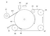
- the molding apparatus 4 as one configuration example includes a molding drum 40, a feeding device 41 for feeding out the resin tape 411 in order along the rotation direction of the molding drum 40, a discharge port 42 for supplying a polyurethane composition, an external heating device 43, An endless belt 44 and the like are included.
- the molding drum 40 includes molding grooves on the outer peripheral surface and an internal heating device (not shown) inside, and is rotated at a predetermined speed by a driving device (not shown).
- the forming groove has a concave cross section carved at a predetermined depth corresponding to the thickness of the elastic body.
- molding groove should just be more than the width
- the internal heating device supplies heat for curing the polyurethane composition.
- the internal heating device is not particularly limited, such as an electric heater, heating oil, steam or the like.
- the heating temperature is determined by the polyurethane composition, the rotation speed, and the like, and is set, for example, in the range of 110 ° C. or higher and 150 ° C. or lower.
- the feeding device 41 feeds the resin tape 411 into the forming groove.
- the resin tape 411 is wound in a roll shape, and is fed out to the center in the width direction of the forming groove as the forming drum 40 rotates.
- the feeding device 41 only needs to hold the roll-shaped resin tape 411 in a rotatable manner, and can be rotated in synchronization with the rotation of the molding drum 40.
- the molding apparatus may be provided with a surface treatment apparatus (not shown) for performing surface treatment before the resin tape fed from the feeding apparatus reaches the molding drum.
- the discharge port 42 continuously supplies a polyurethane composition in which each component is uniformly mixed to the forming groove with a constant discharge amount.
- a resin tape 411 is fed out into the molding groove, and the polyurethane composition is discharged onto the resin tape 411.
- the molding groove is heated by an internal heating device, and the polyurethane composition supplied to the molding groove starts a thermosetting reaction immediately after casting into the molding groove.
- the external heating device 43 is provided as necessary.
- the external heating device 43 heats the polyurethane composition cast into the forming groove from the discharge port 42 from the surface side, and promotes thermosetting on the surface side.
- the cast polyurethane composition is prevented from flowing into the contact point between the molding drum 40 and the endless belt 44 by the thermosetting reaction progressing by the internal heating device and the external heating device 43 to increase the viscosity. .
- liquidity of a polyurethane composition can be reduced rapidly, the band-shaped elastic body B to manufacture can be thickened and a molding speed can be raised.
- the external heating device 43 a non-contact type far infrared ray, laser beam, ultraviolet ray, induction heating or the like can be used.
- the heating temperature is adjusted by the reactivity and viscosity of the polyurethane composition, the production speed, the thickness of the elastic band B to be produced, the distance to the forming groove, and the like.
- the installation position of the external heating device 43 can be adjusted between the discharge port 42 and the preheating roll 45 according to the reactivity of the polyurethane composition and the thickness of the elastic band B to be produced. In this configuration example, it is installed near the top of the forming drum 40.
- the endless belt 44 covers approximately half of the outer periphery of the forming drum 40, and cools the preheating roll 45 that preheats the endless belt 44, the guide roll 46 that adjusts belt running, the tension roll 47 that applies tension, and the endless belt 44. It is wound around the cooling roll 48 and runs in synchronization with the rotation of the forming drum 40.
- the endless belt 44 covers the molding groove of the molding drum 40, thereby forming a cavity filled with the polyurethane composition together with the molding groove. That is, the molding groove and the endless belt 44 have a function as a mold when the polyurethane composition is cured.
- the endless belt 44 is heated by the preheating roll 45, and the temperature of the polyurethane composition is prevented from being lowered when contacting the endless belt 44.
- the section in which the endless belt 44 covers the molding groove is not limited to about a half circumference of the outer periphery of the molding drum 40, and may be any section that is necessary for curing until the polyurethane composition can be peeled from the endless belt 44. Good.
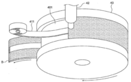
- FIG. 4 the schematic diagram which looked down at the forming drum 40 during elastic body manufacture from upper direction is shown.
- the resin tape 411 is fed out to the center portion in the width direction of the molding groove 401 and wound around the rotation of the molding drum 40.
- the polyurethane composition is supplied from above the resin tape 411 to the molding groove 401 and embeds the resin tape.
- an endless belt (not shown) covers the molding groove, and the polyurethane composition is filled in a cavity formed by the molding groove 401 and the endless belt, and is thermoset in a state where the outer shape is adjusted, and the resin is formed.
- the band-like elastic body B is obtained by integrating the tape 411 and polyurethane.
- the cured elastic band B is peeled off from the endless belt 44 and the forming groove.
- a cooling device 49 for cooling by blowing cool air or the like from the outside of the endless belt 44 can be installed as necessary.
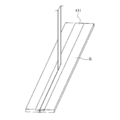
- the peeled strip-shaped elastic body B is cut in the length direction to form a sheet-shaped elastic body S.
- the resin tape 411 becomes the edge part 11 which consists of a tape-shaped base material of the elastic body 1 by being cut
- the blade 3 of the present invention is obtained by joining the obtained elastic body 1 and the support member 2 (FIG. 2).
- the width of the molding groove is three times the width of the elastic body, two resin tapes are fed into the molding groove in parallel, and the obtained belt-like elastic body is divided into three in the width direction.
- An elastic body can also be manufactured.
- by cutting a band-shaped elastic body made using a resin tape having substantially the same width as the forming groove width into a plurality of pieces with a predetermined width an edge portion made of a tape-shaped substrate is formed on the entire width direction of the elastic body.
- the elastic body provided can also be manufactured.
- PCT / JP2014 / 071565 and two or more attachment reference structures are formed, and fitted to the machining reference structure of the blade support.
- a jig that has a fitting structure that fits and can be mounted so that the elastic body joints face each other with two blade supports, and a blade receiving space is provided between the facing parts. Thereby, after joining a blade support body to the both sides of a sheet-like elastic body, it can also cut
- Example 1 The elastic body of the present invention was produced by the continuous molding method described above.
- resin tape an ultra high molecular weight polyethylene tape (manufactured by Nitto Denko Corporation, trade name: No. 440, width 5 mm, thickness 100 ⁇ m) was used.
- Polytetramethylene ether glycol manufactured by Hodogaya Chemical Co., Ltd., trade name: PTG2000SN, number average molecular weight 2000 was dehydrated under reduced pressure at 110 ° C. for 2 hours.
- the resin tape was fed out into the forming groove of the forming drum, and then the above mixed and stirred composition was supplied from the casting machine to the forming groove.
- the supply amount was set so as to just fill the cavity formed by the forming groove and the endless belt.
- the cavity cross-sectional dimensions were a width of 25 mm, a depth of 2 mm, a mold temperature of 140 ° C., and a crosslinking time of 45 seconds.
- the obtained belt-like elastic body was cut to 232 mm in the length direction and then cut in the center in the width direction to obtain an elastic body having an edge portion made of a tape-like base material having a width of 2.5 mm and a thickness of 100 ⁇ m. .
- the elastic body has a width of 12.5 mm and a thickness of 2 mm.
- the elastic body and the support member were joined to manufacture the blade 1.
- Example 2 A blade 2 was produced in the same manner as in Example 1 except that ETFE (manufactured by Asahi Glass Co., Ltd., trade name: Aflex, width 5 mm, thickness 100 ⁇ m) was used as the resin tape.
- Comparative Example 1 A blade 3 was produced in the same manner as in Example 1 except that no resin tape was used.
- Example 3 A blade 4 was produced in the same manner as in Example 1 except that PEEK (manufactured by Victrex (UK), trade name: APTIV film 1000 series, width 5 mm, thickness 50 ⁇ m) was used as the resin tape.
- Example 4 Blade 5 was produced in the same manner as in Example 1 except that PI (manufactured by Toray DuPont, trade name: Kapton 200V, width 5 mm, thickness 50 ⁇ m) was used as the resin tape.
- Example 5" A blade 6 was produced in the same manner as in Example 1 except that PPS (product name: Torelina, width 5 mm, thickness 50 ⁇ m) was used as the resin tape.
- Example 6 A blade 7 was produced in the same manner as in Example 1 except that PET (trade name: Lumirror S10, width 5 mm, thickness 50 ⁇ m) was used as the resin tape.
- Example 7 A blade 8 was produced in the same manner as in Example 1 except that an ultrahigh molecular weight polyethylene tape (manufactured by Nitto Denko Corporation, trade name: No. 440, width 5 mm, thickness 500 ⁇ m) was used as the resin tape. .
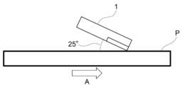
- FIG. 6 the schematic diagram of a friction coefficient measurement test is shown.
- a surface property measuring instrument manufactured by Shinto Kagaku Co., Ltd., device name: TYPE14
- the edge portion of the elastic body 1 of the blades 1 to 8 is brought into contact with the PET film P placed on the flat plate at an angle of 25 degrees.
- the load W was set to 100 g / cm.
- a printing running test (30000 sheets) was conducted using the blades 1 to 8 as cleaning blades of a commercially available digital color multifunction peripheral (manufactured by Ricoh Co., Ltd., MP C2503).
- the edge portion after the test was visually checked for wear and evaluated according to the following criteria. Further, occurrence of inconvenience due to the blade was visually confirmed in the printed matter and the charging roller after the test.
- ⁇ Wear and chipping of 0.01 mm or less are observed at the edge portion.
- ⁇ Abrasion and chipping of 0.03 mm or less are observed at the edge portion.
- X Wear and chipping larger than 0.05 mm are observed at the edge portion.
- Toner slipping ⁇ No slipping ⁇ : Through slipping • External additive slipping ⁇ : No charging roller contamination ⁇ : Charging roller uniformly thinly dirty ⁇ : Charging roller local contamination ⁇ : Fault image due to charging roller contamination Occurrence / toner filming ⁇ : No abnormal image due to filming ⁇ : Abnormal image due to filming appears partially faint ⁇ : Abnormal image due to filming appears faint ⁇ : Abnormal image due to filming is clearly visible
- the blades of the present invention produced in Examples 1 to 7 had a low coefficient of friction, with the edge portion having a dynamic friction coefficient less than half that of the conventional polyurethane blade produced in Comparative Example 1.
- the backup portion is made of conventionally used polyurethane, and is pressed against the photoreceptor by the elasticity of the polyurethane, so that the toner can be prevented from slipping through.
- the blades of the present invention produced in Examples 1 to 7 since the edge portion had low friction, the external additive slipped out and toner filming was not observed. That is, the blade of the present invention can extend the life of the entire system including the photoreceptor to which the blade contacts.
- the life of the blade itself can be remarkably increased as compared with the conventional blades.
- the blades of the present invention manufactured in Examples 1 to 7 can prevent toner filming, they are suitable for use in low-melting-point toners and fine toners that are prone to toner filming.
- the blade manufactured in Comparative Example 1 was confirmed to have an abnormal image due to toner filming and contamination of the charging roller. This is because the dynamic friction coefficient of the edge portion is large and heat is easily generated by frictional heat.
Landscapes
- Engineering & Computer Science (AREA)
- Mechanical Engineering (AREA)
- Physics & Mathematics (AREA)
- General Physics & Mathematics (AREA)
- Cleaning In Electrography (AREA)
- Electrophotography Configuration And Component (AREA)
- Laminated Bodies (AREA)
- Moulding By Coating Moulds (AREA)
Abstract
エッジ部の摩擦係数が低いブレードを提供することを課題とする。解決手段として、テープ状基材からなるエッジ部と、ポリウレタンからなるバックアップ部と、を有する弾性体を提供する。
Description
本発明は、複写機、プリンタ、ファクシミリ、これらの複合機等の電子写真装置のブレードに用いられる弾性体に関する。
複写機、プリンタ等の電子写真装置において、余分なトナーを掻き落とすクリーニングブレードや、現像部におけるトナーの厚さを均一にする現像ブレード等の各種ブレードが用いられている。ブレードは、弾性体と支持部材とからなり、通常、弾性体は、適度な硬度、弾性を有する熱硬化性ポリウレタンが用いられる。
近年、電子写真装置において各部材の長寿命化が進んでおり、弾性体には、耐摩耗性の向上が求められている。また、弾性体には、感光体ドラムへのトナー・外添剤などのフィルミング(固着)防止、感光体ドラムの摩耗低減等、システム全体の長寿命化に寄与することも求められている。これらを達成するために、弾性体は、低い摩擦係数が求められている。
弾性体の摩擦係数を低くするには、硬度を高くすればよい。しかし、ブレード全体の硬度を高くすると、弾性率が増加して感光体ドラムへの圧力が増加してしまう。硬度の高い弾性体を、適切な圧力で感光体ドラムに接触させるには、接触させる角度等が制限されるため、設計の自由度が狭くなってしまう。そのため、エッジ部のみを高硬度化する方法が提案されており、例えば、特許文献1には、エッジ部とベース部(バックアップ部)とを、材質が異なるポリウレタンから形成し、エッジ部のみを高硬度とした弾性体が提案されている。また、特許文献2には、単一なポリウレタンからなる弾性体の像担持体当接部(エッジ部)のみにイソシアネート化合物を含浸させ、像担持体との当接部のみを高硬度化した弾性体が提案されている。
しかし、特許文献1、2に提案されている弾性体は、エッジ部にポリウレタンを使用している以上、高硬度化には限界があった。
しかし、特許文献1、2に提案されている弾性体は、エッジ部にポリウレタンを使用している以上、高硬度化には限界があった。
本発明は、エッジ部の摩擦係数が低いブレードを提供することを課題とする。
1.テープ状基材からなるエッジ部と、
ポリウレタンからなるバックアップ部と、
を有することを特徴とする弾性体。
2.前記テープ状基材の厚さが、3μm以上500μm以下であることを特徴とする1.に記載の弾性体。
3.前記テープ状基材が、超高分子量ポリエチレン、フッ素樹脂、ポリエーテルエーテルケトン、ポリイミド、ポリフェニレンスルフィド、ポリエチレンテレフタレートのいずれかからなることを特徴とする1.または2.に記載の弾性体。
4.1.~3.のいずれかに記載の弾性体と、
前記弾性体と接合された支持部材と、
を有することを特徴とするブレード。
5.外周に成形溝を備えた成形ドラムを回転させながら、前記成形溝に樹脂テープを繰り出す工程、
前記成形ドラムを回転させながら、前記成形溝にポリウレタン組成物を供給する工程、
前記成形ドラムを回転させながら、前記成形ドラムの回転に同期して回走するエンドレスベルトで前記成形溝を覆い、前記ポリウレタン組成物を前記成形溝と前記エンドレスベルトとから形成されるキャビティ内で硬化して帯状弾性体を製造する工程、
前記帯状弾性体を切断する工程、
を有することを特徴とするテープ状基材からなるエッジ部とポリウレタンからなるバックアップ部とを有する弾性体の製造方法。
6.外周に成形溝を備えた成形ドラムを回転させながら、前記成形溝に樹脂テープを繰り出す工程、
前記成形ドラムを回転させながら、前記成形溝にポリウレタン組成物を供給する工程、
前記成形ドラムを回転させながら、前記成形ドラムの回転に同期して回走するエンドレスベルトで前記成形溝を覆い、前記ポリウレタン組成物を前記成形溝と前記エンドレスベルトとから形成されるキャビティ内で硬化して帯状弾性体を製造する工程、
前記帯状弾性体を切断する工程、
を有する製造方法により製造されたテープ状基材からなるエッジ部とポリウレタンからなるバックアップ部とを有する弾性体。
ポリウレタンからなるバックアップ部と、
を有することを特徴とする弾性体。
2.前記テープ状基材の厚さが、3μm以上500μm以下であることを特徴とする1.に記載の弾性体。
3.前記テープ状基材が、超高分子量ポリエチレン、フッ素樹脂、ポリエーテルエーテルケトン、ポリイミド、ポリフェニレンスルフィド、ポリエチレンテレフタレートのいずれかからなることを特徴とする1.または2.に記載の弾性体。
4.1.~3.のいずれかに記載の弾性体と、
前記弾性体と接合された支持部材と、
を有することを特徴とするブレード。
5.外周に成形溝を備えた成形ドラムを回転させながら、前記成形溝に樹脂テープを繰り出す工程、
前記成形ドラムを回転させながら、前記成形溝にポリウレタン組成物を供給する工程、
前記成形ドラムを回転させながら、前記成形ドラムの回転に同期して回走するエンドレスベルトで前記成形溝を覆い、前記ポリウレタン組成物を前記成形溝と前記エンドレスベルトとから形成されるキャビティ内で硬化して帯状弾性体を製造する工程、
前記帯状弾性体を切断する工程、
を有することを特徴とするテープ状基材からなるエッジ部とポリウレタンからなるバックアップ部とを有する弾性体の製造方法。
6.外周に成形溝を備えた成形ドラムを回転させながら、前記成形溝に樹脂テープを繰り出す工程、
前記成形ドラムを回転させながら、前記成形溝にポリウレタン組成物を供給する工程、
前記成形ドラムを回転させながら、前記成形ドラムの回転に同期して回走するエンドレスベルトで前記成形溝を覆い、前記ポリウレタン組成物を前記成形溝と前記エンドレスベルトとから形成されるキャビティ内で硬化して帯状弾性体を製造する工程、
前記帯状弾性体を切断する工程、
を有する製造方法により製造されたテープ状基材からなるエッジ部とポリウレタンからなるバックアップ部とを有する弾性体。
本発明の弾性体は、エッジ部がテープ状基材からなり、エッジ部の摩擦係数を、ポリウレタンでは達成不可能な低い値にすることができる。また、本発明の弾性体は、バックアップ部が、従来用いられているポリウレタンからなる。そのため、本発明の弾性体は、信頼性が高く、従来の弾性体と同等の圧力で感光体に接触しながらも、優れたクリーニング性を有する。
本発明の弾性体は、エッジ部の摩擦係数が低いため、近年、使用が拡大している低融点トナーや微細トナーに対して好適に使用することができる。また、本発明の弾性体は、従来の弾性体と比較して長寿命であり、さらに、弾性体が接する感光体の寿命も長くすることができる。
厚さが3μm以上500μm以下であるテープ状基材は、十分な可撓性を有し、バックアップ部の変形に追従することができるため、バックアップ部から剥がれにくい。また、製造時の取り扱い性にも優れる。
また、テープ状基材として、超高分子量ポリエチレン、フッ素樹脂、ポリエーテルエーテルケトン、ポリイミド、ポリフェニレンスルフィド、ポリエチレンテレフタレートのいずれかを用いることにより、さらに耐摩耗性を向上させることができる。
本発明の弾性体は、外周に成形溝を備える成形ドラムを用いることにより、連続的に製造することができ、生産性に優れている。
本発明の弾性体は、エッジ部の摩擦係数が低いため、近年、使用が拡大している低融点トナーや微細トナーに対して好適に使用することができる。また、本発明の弾性体は、従来の弾性体と比較して長寿命であり、さらに、弾性体が接する感光体の寿命も長くすることができる。
厚さが3μm以上500μm以下であるテープ状基材は、十分な可撓性を有し、バックアップ部の変形に追従することができるため、バックアップ部から剥がれにくい。また、製造時の取り扱い性にも優れる。
また、テープ状基材として、超高分子量ポリエチレン、フッ素樹脂、ポリエーテルエーテルケトン、ポリイミド、ポリフェニレンスルフィド、ポリエチレンテレフタレートのいずれかを用いることにより、さらに耐摩耗性を向上させることができる。
本発明の弾性体は、外周に成形溝を備える成形ドラムを用いることにより、連続的に製造することができ、生産性に優れている。
1 弾性体
11 エッジ部(テープ状基材)
12 バックアップ部
2 支持部材
3 ブレード
4 成形装置
40 成形ドラム
401 成形溝
41 繰出装置
42 吐出口
43 外部加熱装置
44 エンドレスベルト
45 予熱ロール
46 ガイドロール
47 テンションロール
48 冷却ロール
49 冷却装置
411 樹脂テープ
B 帯状弾性体
S シート状弾性体
11 エッジ部(テープ状基材)
12 バックアップ部
2 支持部材
3 ブレード
4 成形装置
40 成形ドラム
401 成形溝
41 繰出装置
42 吐出口
43 外部加熱装置
44 エンドレスベルト
45 予熱ロール
46 ガイドロール
47 テンションロール
48 冷却ロール
49 冷却装置
411 樹脂テープ
B 帯状弾性体
S シート状弾性体
図1に、本発明の弾性体の一構成例を示す。
一構成例である弾性体1は、テープ状基材からなるエッジ部11とポリウレタンからなるバックアップ部12とを有する。
エッジ部11は、テープ状基材からなり、ポリウレタンよりも高硬度、低摩擦である。また、バックアップ部12は、ポリウレタンからなり、弾性体として、適度な弾性を有している。
一構成例である弾性体1は、テープ状基材からなるエッジ部11とポリウレタンからなるバックアップ部12とを有する。
エッジ部11は、テープ状基材からなり、ポリウレタンよりも高硬度、低摩擦である。また、バックアップ部12は、ポリウレタンからなり、弾性体として、適度な弾性を有している。
本発明の弾性体の幅は、5mm以上20mm以下、厚さは1mm以上3mm以下程度である。また、弾性体の長さは、接触する感光体ドラムの幅、すなわち、印刷する用紙の幅に応じて適宜選択されるが、A4サイズの紙を使用する場合、220mm程度である。また、エッジ部とバックアップ部とは、一目で区別できるように、異なる色を有することが好ましい。
「エッジ部」
エッジ部11は、テープ状基材からなり、弾性体1の長さ方向の一辺に沿って設けられ、弾性体1の厚さ方向断面における一つの角を構成している。そして、弾性体1は、エッジ部11からなる辺または面で感光体ドラムに接触する。なお、本発明の弾性体において、エッジ部は、弾性体の幅方向全面に設けることもできる。
エッジ部11は、テープ状基材からなり、弾性体1の長さ方向の一辺に沿って設けられ、弾性体1の厚さ方向断面における一つの角を構成している。そして、弾性体1は、エッジ部11からなる辺または面で感光体ドラムに接触する。なお、本発明の弾性体において、エッジ部は、弾性体の幅方向全面に設けることもできる。
エッジ部を構成するテープ状基材としては、ポリウレタンよりも摩擦係数が低い材料であれば特に限定されず、例えば、超高分子量ポリエチレン(UHMWPE)、ポリテトラフルオロエチレン(PTFE)、テトラフルオロエチレン・パーフルオロアルキルビニルエーテル共重合体(PFA)、テトラフルオロエチレン・ヘキサフルオロプロピレン共重合体(FEP)、テトラフルオロエチレン・エチレン共重合体(ETFE)等のフッ素樹脂、ポリアセタール樹脂(POM)、ポリアミド樹脂(PA)、ポリイミド(PI)、ポリエーテルエーテルケトン(PEEK)、ポリフェニレンスルフィド(PPS)、ポリエチレンテレフタレート(PET)、ポリカーボネート(PC)等を好適に利用することができる。これらの中で、特に耐摩耗性に優れる超高分子量ポリエチレン、ポリテトラフルオロエチレン、テトラフルオロエチレン・パーフルオロアルキルビニルエーテル共重合体、テトラフルオロエチレン・ヘキサフルオロプロピレン共重合体、テトラフルオロエチレン・エチレン共重合体等のフッ素樹脂、ポリエーテルエーテルケトン、ポリイミド、ポリフェニレンスルフィド、ポリエチレンテレフタレートが好ましい。なお、超高分子量ポリエチレンとは、重量平均分子量を100万以上に高めたポリエチレンのことであり、例えば、商品名Dyneema(蘭DSM社)、Spectra(米ハネウェル社)として市販されている。
テープ状基材は、製造時、使用時の変形に追従できるだけの可撓性を有する必要がある。そのため、テープ状基材の厚さは薄いほうが好ましく、500μm以下が好ましく、300μm以下がより好ましく、100μm以下がさらに好ましく、50μm以下が最も好ましい。テープ状基材の厚さの下限値は特に制限されないが、製造時の取り扱い性から、3μm以上あればよい。また、弾性体からテープ状基材が剥がれることを防止する為に、弾性体全体の厚さに対するテープ状基材の厚さは、50%以下であることが好ましく、30%以下であることがより好ましく、10%以下であることがさらに好ましく、5%以下であることが最も好ましい。
テープ状基材の幅は、特に制限されないが、一般に幅が狭いほど安価であるため、幅が狭い方が好ましい。ただし、製造時の取り扱い性の点から、テープ状基材の幅は2mm以上であることが好ましい。
なお、弾性体のエッジ部は、テープ状基材からなるため、エッジ部の厚さ、幅は、テープ状基材の厚さ、幅と同一となる。
テープ状基材の幅は、特に制限されないが、一般に幅が狭いほど安価であるため、幅が狭い方が好ましい。ただし、製造時の取り扱い性の点から、テープ状基材の幅は2mm以上であることが好ましい。
なお、弾性体のエッジ部は、テープ状基材からなるため、エッジ部の厚さ、幅は、テープ状基材の厚さ、幅と同一となる。
テープ状基材は、バックアップ部を構成するポリウレタンとの接着性を向上させるための表面処理を施すことが好ましい。表面処理の方法としては特に制限されず、火炎処理、コロナ処理、プラズマ処理、UV処理、オゾン処理、化学処理、粗面化処理等が挙げられる。
また、テープ状基材とバックアップ部を構成するポリウレタンとの間に、接着剤層を設けることもできる。
「バックアップ部」
バックアップ部12は、ポリウレタンからなる。ポリウレタンは、ポリオールとポリイソシアネートとを含有するポリウレタン組成物を反応させて得られる。
バックアップ部は、ポリウレタンの弾性により、エッジ部を感光体ドラムに適度な圧力で押し付けて接触させるものである。バックアップ部の厚さ(エッジ部が、弾性体の幅方向の一部に設けられている場合は、弾性体の厚さと等しい)は、弾性体に適度なコシの強さを付与できる範囲であればよく、通常、500μm以上3mm以下程度である。
バックアップ部12は、ポリウレタンからなる。ポリウレタンは、ポリオールとポリイソシアネートとを含有するポリウレタン組成物を反応させて得られる。
バックアップ部は、ポリウレタンの弾性により、エッジ部を感光体ドラムに適度な圧力で押し付けて接触させるものである。バックアップ部の厚さ(エッジ部が、弾性体の幅方向の一部に設けられている場合は、弾性体の厚さと等しい)は、弾性体に適度なコシの強さを付与できる範囲であればよく、通常、500μm以上3mm以下程度である。
「ポリオール」
ポリオールとしては、ポリエチレングルコール、ポリプロピレングリコール、ポリオキシテトラメチレングリコール等のポリオキシアルキレングリコール類、あるいは、ビスフェノールA、グリセリンのエチレンオキシド、プロピレンオキシド等のアルキレンオキシド付加物類のポリエーテル型ポリオール;アジピン酸、無水フタル酸、イソフタル酸、マレイン酸、フマール酸等の2塩基酸とエチレングリコール、プロピレングリコール、1,4-ブタンジオール、1,6-ヘキサンジオール、トリメチロールプロパン等のグリコール類との重合反応により得られるポリエステル型ポリオール;ポリカプロラクトンジオール;ポリカーボネートジオール等を挙げることができる。
これらの中で、粘弾性の環境依存性が少ないポリエーテル型ポリオールが好ましい。
ポリオールとしては、ポリエチレングルコール、ポリプロピレングリコール、ポリオキシテトラメチレングリコール等のポリオキシアルキレングリコール類、あるいは、ビスフェノールA、グリセリンのエチレンオキシド、プロピレンオキシド等のアルキレンオキシド付加物類のポリエーテル型ポリオール;アジピン酸、無水フタル酸、イソフタル酸、マレイン酸、フマール酸等の2塩基酸とエチレングリコール、プロピレングリコール、1,4-ブタンジオール、1,6-ヘキサンジオール、トリメチロールプロパン等のグリコール類との重合反応により得られるポリエステル型ポリオール;ポリカプロラクトンジオール;ポリカーボネートジオール等を挙げることができる。
これらの中で、粘弾性の環境依存性が少ないポリエーテル型ポリオールが好ましい。
「ポリイソシアネート」
ポリイソシアネートとしては、メタキシレンジイソシアネート(XDI)、トリレンジイソシアネート(TDI)、4,4-ジフェニルメタンジイソシアネート(MDI)、ヘキサメチレンジイソシアネート(HDI)、イソホロンジイソシアネート(IPDI)、1,4-シクロヘキサンジイソシアネート等を挙げることができる。
ポリイソシアネートとしては、メタキシレンジイソシアネート(XDI)、トリレンジイソシアネート(TDI)、4,4-ジフェニルメタンジイソシアネート(MDI)、ヘキサメチレンジイソシアネート(HDI)、イソホロンジイソシアネート(IPDI)、1,4-シクロヘキサンジイソシアネート等を挙げることができる。
上記のポリウレタンの製造においては、OH基/NCO基の当量比は生成するポリウレタンの物性から0.80以上1.10以下が好ましく、0.90以上1.05以下がより好ましい。
ポリウレタン組成物には、上記したポリオール、ポリイソシアネート以外に、架橋剤(鎖延長剤)、界面活性剤、難燃剤、着色剤、充填剤、可塑剤、安定剤、離型剤、触媒等の添加剤を配合することができる。また、導電剤、研磨剤を配合することもできる。
架橋剤(鎖延長剤)としては、エチレングリコール、1,4-ブタンジオール、ジエチレングリコール、1,6-ヘキサンジオール、ネオペンチルグリコール等の低分子量ジオール並びにエチレンジアミン、ヘキサメチレンジアミン、イソホロンジアミン等のジアミンを挙げることができる。望ましくは、低分子量ジオールが用いられる。さらに必要に応じて多官能成分としてトリメチロールプロパン、グリセリン等のトリオール、トリエタノールアミン等のトリアミン、及びこれらのエチレンオキシド、プロピレンオキシド付加物を添加することもできる。
また、必要に応じて一般的なアミン化合物や有機錫系化合物等の反応促進剤を用いることができる。例えば、特許第2942183号公報、第0022~0023段落に開示されるイミダゾール誘導体等が挙げられる。その具体例としては、化学構造上から反応温度依存性の高い2-メチルイミダゾールや1,2-ジメチルイミダゾール等を挙げることができる。
反応促進剤は、ポリオールとポリイソシアネート合計100重量部に対して、0.001重量部以上0.5重量部以下の範囲で用いることが好ましく、0.01重量部以上0.3重量部以下の範囲で用いることがより好ましい。反応促進剤としては、感温性、あるいは遅効性を有するものが、反応促進剤を混合したウレタン樹脂組成物が成形前に硬化してしまうことを防ぎ、可使時間を長くでき、脱型時間が短くなるため好ましい。具体的には、ブロックアミンと称される1,8-ジアザビシクロ(5,4,0)ウンデセン-7-有機酸塩、1,5-ジアザビシクロ(4,3,0)ノネン-5-有機酸塩、またはこれらの混合物等が挙げられる。
反応促進剤は、ポリオールとポリイソシアネート合計100重量部に対して、0.001重量部以上0.5重量部以下の範囲で用いることが好ましく、0.01重量部以上0.3重量部以下の範囲で用いることがより好ましい。反応促進剤としては、感温性、あるいは遅効性を有するものが、反応促進剤を混合したウレタン樹脂組成物が成形前に硬化してしまうことを防ぎ、可使時間を長くでき、脱型時間が短くなるため好ましい。具体的には、ブロックアミンと称される1,8-ジアザビシクロ(5,4,0)ウンデセン-7-有機酸塩、1,5-ジアザビシクロ(4,3,0)ノネン-5-有機酸塩、またはこれらの混合物等が挙げられる。
本発明の弾性体は、下記で詳述するように、外周に成形溝を備えた成形ドラムを用いる連続成形法により製造することができる。連続成形法では、ポリウレタン組成物が、成形ドラムの成形溝に注型されてから帯状弾性体として取り出されるまでの時間は、成形ドラムが約半回転する30~60秒程度である。ポリウレタン組成物は、30~60秒程度で成形ドラムから剥離可能な程度に重合するように、ポリオール、ポリイソシアネート、架橋剤、触媒等を選定し、組成を設計する。
「ブレード」
図2に、本発明のブレードの一構成例を示す。
一構成例であるブレード3は、テープ状基材からなるエッジ部11とポリウレタンからなるバックアップ部12とを有する弾性体1と、この弾性体1に接合された支持部材2とを有する。弾性体と支持部材との接合方法は、強固に接合できるものであれば特に制限されず、接着剤、両面テープ等を用いることができる。また、支持部材の形状や、弾性体の支持部材との接合箇所は特に制限されず、ブレードを設置する感光体周囲のスペース等に応じて、適宜設計することができる。
図2に、本発明のブレードの一構成例を示す。
一構成例であるブレード3は、テープ状基材からなるエッジ部11とポリウレタンからなるバックアップ部12とを有する弾性体1と、この弾性体1に接合された支持部材2とを有する。弾性体と支持部材との接合方法は、強固に接合できるものであれば特に制限されず、接着剤、両面テープ等を用いることができる。また、支持部材の形状や、弾性体の支持部材との接合箇所は特に制限されず、ブレードを設置する感光体周囲のスペース等に応じて、適宜設計することができる。
「弾性体の製造方法」
本発明の弾性体は、連続成形法により製造することができる。
連続成形法による、本発明の弾性体の製造方法は、
1.外周に成形溝を備えた成形ドラムを回転させながら、前記成形溝に樹脂テープを繰り出す工程、
2.前記成形ドラムを回転させながら、前記成形溝にポリウレタン組成物を供給する工程、
3.前記成形ドラムを回転させながら、前記成形ドラムの回転に同期して回走するエンドレスベルトで前記成形溝を覆い、前記ポリウレタン組成物を前記成形溝と前記エンドレスベルトとから形成されるキャビティ内で硬化して帯状弾性体を製造する工程、
4.前記帯状弾性体を切断する工程、
を少なくとも有する。
本発明の弾性体は、連続成形法により製造することができる。
連続成形法による、本発明の弾性体の製造方法は、
1.外周に成形溝を備えた成形ドラムを回転させながら、前記成形溝に樹脂テープを繰り出す工程、
2.前記成形ドラムを回転させながら、前記成形溝にポリウレタン組成物を供給する工程、
3.前記成形ドラムを回転させながら、前記成形ドラムの回転に同期して回走するエンドレスベルトで前記成形溝を覆い、前記ポリウレタン組成物を前記成形溝と前記エンドレスベルトとから形成されるキャビティ内で硬化して帯状弾性体を製造する工程、
4.前記帯状弾性体を切断する工程、
を少なくとも有する。
「成形装置」
弾性体の連続成形法に用いる成形装置の一構成例を図3に示す。本発明の弾性体の製造方法の一例を、一構成例である成形装置とともに説明する。
一構成例である成形装置4は、成形ドラム40と、成形ドラム40の回転方向に沿って順に、樹脂テープ411を繰り出す繰出装置41、ポリウレタン組成物を供給する吐出口42、外部加熱装置43、エンドレスベルト44等を有する。
弾性体の連続成形法に用いる成形装置の一構成例を図3に示す。本発明の弾性体の製造方法の一例を、一構成例である成形装置とともに説明する。
一構成例である成形装置4は、成形ドラム40と、成形ドラム40の回転方向に沿って順に、樹脂テープ411を繰り出す繰出装置41、ポリウレタン組成物を供給する吐出口42、外部加熱装置43、エンドレスベルト44等を有する。
成形ドラム40は、外周面に成形溝、内部に内部加熱装置(図示せず)を備え、駆動装置(図示せず)により所定速度で回転する。
成形溝は、弾性体の厚みに相当する所定の深さで彫り込まれた断面凹状である。成形溝の幅は、弾性体の幅以上であればよいが、弾性体の2倍幅とすることが好ましい。成形溝の幅が、弾性体の2倍幅であれば、得られた帯状弾性体Bを、所定の長さと幅方向中央とで切断することにより、効率的に弾性体を製造することができる。
内部加熱装置は、ポリウレタン組成物を硬化させる熱を供給する。内部加熱装置は、電気ヒータ、加熱オイル、蒸気等、特に限定されるものではない。その加熱温度は、ポリウレタン組成物や回転速度等によって決定され、例えば110℃以上150℃以下の範囲で設定される。
成形溝は、弾性体の厚みに相当する所定の深さで彫り込まれた断面凹状である。成形溝の幅は、弾性体の幅以上であればよいが、弾性体の2倍幅とすることが好ましい。成形溝の幅が、弾性体の2倍幅であれば、得られた帯状弾性体Bを、所定の長さと幅方向中央とで切断することにより、効率的に弾性体を製造することができる。
内部加熱装置は、ポリウレタン組成物を硬化させる熱を供給する。内部加熱装置は、電気ヒータ、加熱オイル、蒸気等、特に限定されるものではない。その加熱温度は、ポリウレタン組成物や回転速度等によって決定され、例えば110℃以上150℃以下の範囲で設定される。
繰出装置41は、樹脂テープ411を成形溝に繰り出すものである。樹脂テープ411は、ロール状に巻かれており、成形ドラム40の回転に従って、成形溝の幅方向中央に繰り出される。繰出装置41は、ロール状の樹脂テープ411を回転可能に保持するものであればよく、成形ドラム40の回転と同期して回転させることもできる。成形装置には、繰出装置から繰り出した樹脂テープが成形ドラムに達する前に、表面処理を行う表面処理装置(図示せず)を設けることもできる。
吐出口42は、各成分が均一に混合されたポリウレタン組成物を、一定の吐出量で成形溝に連続して供給する。成形溝には、樹脂テープ411が繰り出されており、ポリウレタン組成物は、樹脂テープ411上に吐出される。成形溝は、内部加熱装置により加熱されており、成形溝に供給されたポリウレタン組成物は、成形溝への注型直後から熱硬化反応を開始する。
外部加熱装置43は、必要に応じて設けられる。外部加熱装置43は、吐出口42から成形溝に注型されたポリウレタン組成物を、表面側から加熱して、表面側の熱硬化を促進する。注型されたポリウレタン組成物は、内部加熱装置と外部加熱装置43とによって熱硬化反応が進行して粘度が上がることにより、成形ドラム40とエンドレスベルト44との接触点への流れ込みが抑制される。また、ポリウレタン組成物の流動性を素早く低下させることができるため、製造する帯状弾性体Bを厚くすること、成形スピードを上げることができる。
外部加熱装置43としては、非接触タイプである遠赤外線、レーザー光、紫外線、誘導加熱等を使用することができる。加熱温度は、ポリウレタン組成物の反応性や粘度、製造スピード、製造する帯状弾性体Bの厚さ、成形溝までの距離等によって調整する。また、外部加熱装置43の設置位置は、吐出口42と予熱ロール45の間でポリウレタン組成物の反応性や製造する帯状弾性体Bの厚みに応じて調整することができる。本構成例では、成形ドラム40の頂点上方付近に設置している。
エンドレスベルト44は、成形ドラム40外周の約半周部分を覆い、このエンドレスベルト44を予熱する予熱ロール45、ベルト走行を調整するガイドロール46、張力を付与するテンションロール47およびエンドレスベルト44を冷却する冷却ロール48に掛け渡されて、成形ドラム40の回転に同期して回走する。
エンドレスベルト44は、成形ドラム40の成形溝を覆うことで、ポリウレタン組成物が充満するキャビティを、成形溝と共に形成する。すなわち、成形溝とエンドレスベルト44とは、ポリウレタン組成物が硬化する際の金型としての機能を有する。また、エンドレスベルト44は、予熱ロール45により加熱されており、ポリウレタン組成物の温度が、エンドレスベルト44との接触時に低下することを防止する。なお、エンドレスベルト44が成形溝を覆う区間は、成形ドラム40外周の約半周部分に限定されず、ポリウレタン組成物がエンドレスベルト44から剥離可能となるまで硬化するのに必要な区間以上であればよい。
エンドレスベルト44は、成形ドラム40の成形溝を覆うことで、ポリウレタン組成物が充満するキャビティを、成形溝と共に形成する。すなわち、成形溝とエンドレスベルト44とは、ポリウレタン組成物が硬化する際の金型としての機能を有する。また、エンドレスベルト44は、予熱ロール45により加熱されており、ポリウレタン組成物の温度が、エンドレスベルト44との接触時に低下することを防止する。なお、エンドレスベルト44が成形溝を覆う区間は、成形ドラム40外周の約半周部分に限定されず、ポリウレタン組成物がエンドレスベルト44から剥離可能となるまで硬化するのに必要な区間以上であればよい。
図4に、弾性体製造中の成形ドラム40を上方から俯瞰した模式図を示す。
樹脂テープ411が、成形溝401の幅方向中央部に繰り出され、成形ドラム40の回転に伴い巻き付けられる。ポリウレタン組成物は、樹脂テープ411の上から成形溝401に供給され、樹脂テープを包埋する。続いて、エンドレスベルト(図示せず)が成形溝を覆い、ポリウレタン組成物は、成形溝401とエンドレスベルトとが形成するキャビティ内に充填され、外形が整えられた状態で熱硬化して、樹脂テープ411とポリウレタンとが一体化した帯状弾性体Bとなる。
樹脂テープ411が、成形溝401の幅方向中央部に繰り出され、成形ドラム40の回転に伴い巻き付けられる。ポリウレタン組成物は、樹脂テープ411の上から成形溝401に供給され、樹脂テープを包埋する。続いて、エンドレスベルト(図示せず)が成形溝を覆い、ポリウレタン組成物は、成形溝401とエンドレスベルトとが形成するキャビティ内に充填され、外形が整えられた状態で熱硬化して、樹脂テープ411とポリウレタンとが一体化した帯状弾性体Bとなる。
硬化した帯状弾性体Bは、エンドレスベルト44と成形溝とから剥離される。帯状弾性体Bを剥離する直前には、エンドレスベルト44の外側から冷風等を吹き付けて冷却する冷却装置49を必要に応じて設置することができる。
剥離された帯状弾性体Bは、長さ方向に切断され、シート状弾性体Sとなる。
このシート状弾性体Sを、幅方向中央部で樹脂テープ411とともに切断することにより(図5)、二本の本発明の弾性体1を製造することができる(図1)。樹脂テープ411は、切断されることにより、弾性体1のテープ状基材からなるエッジ部11となる。そして、切断により生じた新たな角はシャープであるため、そのままエッジ部11として用いることができる。
続いて、得られた弾性体1と支持部材2とを接合することにより、本発明のブレード3が得られる(図2)。
剥離された帯状弾性体Bは、長さ方向に切断され、シート状弾性体Sとなる。
このシート状弾性体Sを、幅方向中央部で樹脂テープ411とともに切断することにより(図5)、二本の本発明の弾性体1を製造することができる(図1)。樹脂テープ411は、切断されることにより、弾性体1のテープ状基材からなるエッジ部11となる。そして、切断により生じた新たな角はシャープであるため、そのままエッジ部11として用いることができる。
続いて、得られた弾性体1と支持部材2とを接合することにより、本発明のブレード3が得られる(図2)。
上記製造方法は一例であり、例えば、成形溝幅を弾性体の3倍幅とし、2本の樹脂テープを平行に成形溝に繰り出し、得られた帯状弾性体を幅方向で3分割して、弾性体を製造することもできる。また、成形溝幅とほぼ同幅の樹脂テープを用いて作成した帯状弾性体を、所定の幅で複数本に切断することにより、弾性体の幅方向全面にテープ状基材からなるエッジ部を備える弾性体を製造することもできる。さらに、国際出願番号PCT/JP2014/071565に記載の2つ以上の加工基準構造と、2つ以上の取付基準構造とが形成されているブレード支持体と、このブレード支持体の加工基準構造に嵌合する嵌合構造を有し、2本のブレード支持体を弾性体接合部が対向するように載置することができ、その対向間部に刃受け空間が設けられている治具とを用いることにより、シート状弾性体の両側部にブレード支持体を接合した後に、長さ方向に切断することもできる。また、検査、梱包、出荷等の工程を有することもできる。
さらに、予め、片面に接着剤層が設けられたテープ状基材を用いること、あるいは、繰出装置と成形ドラムとの間にテープ状基材の片面に接着剤を塗布する塗布装置を設けることもできる。
「実施例1」
上記した連続成形法により、本発明の弾性体を製造した。
樹脂テープとしては、超高分子量ポリエチレンテープ(日東電工株式会社製、商品名:No.440、幅5mm、厚さ100μm)を用いた。
ポリテトラメチレンエーテルグリコール(保土谷化学工業株式会社製、商品名:PTG2000SN、数平均分子量2000)を110℃で2時間減圧脱水した。このポリオール100重量部に対し、ポリイソシアネートとして4,4-ジフェニルメタンジイソシアネート(MDI)(東ソー株式会社製、商品名:モノメリックMDI)を103重量部加え、100℃で3時間、窒素雰囲気下で合成し、プレポリマーを得た。このプレポリマーのNCO%は、14.7%である。
注型機のプレポリマー用タンクに上記プレポリマー(100重量部)、ポリオール用タンクにポリテトラメチレンエーテルグリコール(PTG2000SN)(80重量部)、架橋剤用タンクに1,4-ブタンジオール(9.2重量部)、1,1,1-トリメチロールプロパン(2.3重量部)、1,8-ジアザビシクロ(5,4,0)-ウンデセン-7(0.2重量部)を仕込み(液温60℃)、混合撹拌した。
上記した連続成形法により、本発明の弾性体を製造した。
樹脂テープとしては、超高分子量ポリエチレンテープ(日東電工株式会社製、商品名:No.440、幅5mm、厚さ100μm)を用いた。
ポリテトラメチレンエーテルグリコール(保土谷化学工業株式会社製、商品名:PTG2000SN、数平均分子量2000)を110℃で2時間減圧脱水した。このポリオール100重量部に対し、ポリイソシアネートとして4,4-ジフェニルメタンジイソシアネート(MDI)(東ソー株式会社製、商品名:モノメリックMDI)を103重量部加え、100℃で3時間、窒素雰囲気下で合成し、プレポリマーを得た。このプレポリマーのNCO%は、14.7%である。
注型機のプレポリマー用タンクに上記プレポリマー(100重量部)、ポリオール用タンクにポリテトラメチレンエーテルグリコール(PTG2000SN)(80重量部)、架橋剤用タンクに1,4-ブタンジオール(9.2重量部)、1,1,1-トリメチロールプロパン(2.3重量部)、1,8-ジアザビシクロ(5,4,0)-ウンデセン-7(0.2重量部)を仕込み(液温60℃)、混合撹拌した。
樹脂テープを成形ドラムの成形溝に繰り出し、続いて、注型機から上記混合撹拌した組成物を成形溝に供給した。供給量は、成形溝とエンドレスベルトからなるキャビティーを丁度満たす量とした。キャビティー断面寸法は幅25mm、深さ2mm、金型温度は140℃、架橋時間は45秒とした。
得られた帯状弾性体を、長さ方向で232mmに切断し、次いで幅方向の中心で切断し、幅2.5mm、厚さ100μmのテープ状基材からなるエッジ部を有する弾性体を得た。弾性体の幅は12.5mm、厚さは2mmである。この弾性体と支持部材とを接合して、ブレード1を製造した。
得られた帯状弾性体を、長さ方向で232mmに切断し、次いで幅方向の中心で切断し、幅2.5mm、厚さ100μmのテープ状基材からなるエッジ部を有する弾性体を得た。弾性体の幅は12.5mm、厚さは2mmである。この弾性体と支持部材とを接合して、ブレード1を製造した。
「実施例2」
樹脂テープとして、ETFE(旭硝子株式会社製、商品名:アフレックス、幅5mm、厚さ100μm)を用いた以外は、上記実施例1と同様にして、ブレード2を製造した。
「比較例1」
樹脂テープを用いない以外は、上記実施例1と同様にして、ブレード3を製造した。
樹脂テープとして、ETFE(旭硝子株式会社製、商品名:アフレックス、幅5mm、厚さ100μm)を用いた以外は、上記実施例1と同様にして、ブレード2を製造した。
「比較例1」
樹脂テープを用いない以外は、上記実施例1と同様にして、ブレード3を製造した。
「実施例3」
樹脂テープとして、PEEK(Victrex社(英国)製、商品名:APTIVフィルム1000シリーズ、幅5mm、厚さ50μm)を用いた以外は、上記実施例1と同様にして、ブレード4を製造した。
「実施例4」
樹脂テープとして、PI(東レ・デュポン株式会社製、商品名:カプトン200V、幅5mm、厚さ50μm)を用いた以外は、上記実施例1と同様にして、ブレード5を製造した。
樹脂テープとして、PEEK(Victrex社(英国)製、商品名:APTIVフィルム1000シリーズ、幅5mm、厚さ50μm)を用いた以外は、上記実施例1と同様にして、ブレード4を製造した。
「実施例4」
樹脂テープとして、PI(東レ・デュポン株式会社製、商品名:カプトン200V、幅5mm、厚さ50μm)を用いた以外は、上記実施例1と同様にして、ブレード5を製造した。
「実施例5」
樹脂テープとして、PPS(東レ株式会社製、商品名:トレリナ、幅5mm、厚さ50μm)を用いた以外は、上記実施例1と同様にして、ブレード6を製造した。
「実施例6」
樹脂テープとして、PET(東レ株式会社製、商品名:ルミラーS10、幅5mm、厚さ50μm)を用いた以外は、上記実施例1と同様にして、ブレード7を製造した。
「実施例7」
樹脂テープとして、超高分子量ポリエチレンテープ(日東電工株式会社製、商品名:No.440、幅5mm、厚さ500μm)を用いた以外は、上記実施例1と同様にして、ブレード8を製造した。
樹脂テープとして、PPS(東レ株式会社製、商品名:トレリナ、幅5mm、厚さ50μm)を用いた以外は、上記実施例1と同様にして、ブレード6を製造した。
「実施例6」
樹脂テープとして、PET(東レ株式会社製、商品名:ルミラーS10、幅5mm、厚さ50μm)を用いた以外は、上記実施例1と同様にして、ブレード7を製造した。
「実施例7」
樹脂テープとして、超高分子量ポリエチレンテープ(日東電工株式会社製、商品名:No.440、幅5mm、厚さ500μm)を用いた以外は、上記実施例1と同様にして、ブレード8を製造した。
得られたブレードを、下記基準にて評価した。結果を表1に示す。
<評価>
・摩擦係数
図6に、摩擦係数測定試験の模式図を示す。表面性測定機(新東科学株式会社製、装置名:TYPE14)を用い、その平板上に設置したPETフィルムPに、ブレード1~8の弾性体1のエッジ部を角度25度で当接させ、荷重Wが100g/cmとなるように設定した。次に、PETフィルムを移動速度100mm/秒で矢印A方向に移動させた際の抵抗値Fを測定し、各ブレードのPETフィルムに対する23℃での動摩擦係数μ=F/W(単位なし)を測定した。測定は、各ブレードについて3回行い、その相加平均値を示す。
(試験方法・条件)
試験機 :新東科学株式会社製、装置名:TYPE14
試験環境:23℃
相手材 :PETフィルム(未処理面)
荷重 :100g
当接角 :25°(専用治具)
摺動方向:トレーリング
摺動巾 :20mm
摺動速度:100mm/sec
計算式 :μ=F/W
<評価>
・摩擦係数
図6に、摩擦係数測定試験の模式図を示す。表面性測定機(新東科学株式会社製、装置名:TYPE14)を用い、その平板上に設置したPETフィルムPに、ブレード1~8の弾性体1のエッジ部を角度25度で当接させ、荷重Wが100g/cmとなるように設定した。次に、PETフィルムを移動速度100mm/秒で矢印A方向に移動させた際の抵抗値Fを測定し、各ブレードのPETフィルムに対する23℃での動摩擦係数μ=F/W(単位なし)を測定した。測定は、各ブレードについて3回行い、その相加平均値を示す。
(試験方法・条件)
試験機 :新東科学株式会社製、装置名:TYPE14
試験環境:23℃
相手材 :PETフィルム(未処理面)
荷重 :100g
当接角 :25°(専用治具)
摺動方向:トレーリング
摺動巾 :20mm
摺動速度:100mm/sec
計算式 :μ=F/W
・印字テスト
上記ブレード1~8を、市販のデジタルカラー複合機(株式会社リコー製、MP C2503)のクリーニングブレードとして印字走行試験(30000枚)を実施した。
試験後のエッジ部の摩耗を目視で確認し、下記基準で評価した。また、試験後の印刷物と帯電ローラに、ブレード起因の不都合の発生を目視で確認した。
・耐摩耗性(エッジ部)
◎: エッジ部に変形が見られない。
○: エッジ部に0.01mm以下の摩耗、欠けが見られる。
△: エッジ部に0.03mm以下の摩耗、欠けが見られる。
×: エッジ部に0.05mmより大きな摩耗、欠けが見られる。
上記ブレード1~8を、市販のデジタルカラー複合機(株式会社リコー製、MP C2503)のクリーニングブレードとして印字走行試験(30000枚)を実施した。
試験後のエッジ部の摩耗を目視で確認し、下記基準で評価した。また、試験後の印刷物と帯電ローラに、ブレード起因の不都合の発生を目視で確認した。
・耐摩耗性(エッジ部)
◎: エッジ部に変形が見られない。
○: エッジ部に0.01mm以下の摩耗、欠けが見られる。
△: エッジ部に0.03mm以下の摩耗、欠けが見られる。
×: エッジ部に0.05mmより大きな摩耗、欠けが見られる。
・トナーすり抜け
○: すり抜けなし
×: すり抜けあり
・外添剤すり抜け
◎:帯電ローラの汚れなし
○:帯電ローラが均一に薄ら汚れ
△:帯電ローラが局所的に汚れ
×:帯電ローラ汚れによる不具合画像発生
・トナーフィルミング
◎:フィルミングによる異常画像なし
○:フィルミングによる異常画像が部分的に薄ら見える
△:フィルミングによる異常画像が薄ら見える
×:フィルミングによる異常画像がはっきり見える
○: すり抜けなし
×: すり抜けあり
・外添剤すり抜け
◎:帯電ローラの汚れなし
○:帯電ローラが均一に薄ら汚れ
△:帯電ローラが局所的に汚れ
×:帯電ローラ汚れによる不具合画像発生
・トナーフィルミング
◎:フィルミングによる異常画像なし
○:フィルミングによる異常画像が部分的に薄ら見える
△:フィルミングによる異常画像が薄ら見える
×:フィルミングによる異常画像がはっきり見える

実施例1~7で製造した本発明のブレードは、比較例1で製造した従来のポリウレタンからなるブレードと比較して、エッジ部の動摩擦係数が半分以下であり低摩擦であった。また、本発明のブレードは、バックアップ部が従来用いられているポリウレタンからなり、ポリウレタンの弾性により感光体に押し付けられているため、トナーのすり抜けを防止することができた。
実施例1~7で製造した本発明のブレードは、エッジ部が低摩擦であるため、外添剤のすり抜け、トナーフィルミングが見られなかった。すなわち、本発明のブレードにより、ブレードが接触する感光体を含むシステム全体を長寿命化できる。特に、エッジ部に耐摩耗性に優れた素材である超高分子量ポリエチレン、ポリエーテルエーテルケトン、ポリイミドを使用した実施例1、3、4は、30000枚印字後もエッジ部の変形が全く見られず、これまでのブレードと比較してブレード自体を顕著に長寿命化することができる。また、実施例1~7で製造した本発明のブレードは、トナーフィルミングを防止することができるため、トナーフィルミングが起こりやすい低融点トナーや微細トナーへの使用に適している。
それに対し、比較例1で製造したブレードは、トナーフィルミングによる異常画像と、帯電ローラの汚れが確認できた。これは、エッジ部の動摩擦係数が大きく、摩擦熱により発熱しやすいためである。
実施例1~7で製造した本発明のブレードは、エッジ部が低摩擦であるため、外添剤のすり抜け、トナーフィルミングが見られなかった。すなわち、本発明のブレードにより、ブレードが接触する感光体を含むシステム全体を長寿命化できる。特に、エッジ部に耐摩耗性に優れた素材である超高分子量ポリエチレン、ポリエーテルエーテルケトン、ポリイミドを使用した実施例1、3、4は、30000枚印字後もエッジ部の変形が全く見られず、これまでのブレードと比較してブレード自体を顕著に長寿命化することができる。また、実施例1~7で製造した本発明のブレードは、トナーフィルミングを防止することができるため、トナーフィルミングが起こりやすい低融点トナーや微細トナーへの使用に適している。
それに対し、比較例1で製造したブレードは、トナーフィルミングによる異常画像と、帯電ローラの汚れが確認できた。これは、エッジ部の動摩擦係数が大きく、摩擦熱により発熱しやすいためである。
Claims (6)
- テープ状基材からなるエッジ部と、
ポリウレタンからなるバックアップ部と、
を有することを特徴とする弾性体。 - 前記テープ状基材の厚さが、3μm以上500μm以下であることを特徴とする請求項1に記載の弾性体。
- 前記テープ状基材が、超高分子量ポリエチレン、フッ素樹脂、ポリエーテルエーテルケトン、ポリイミド、ポリフェニレンスルフィド、ポリエチレンテレフタレートのいずれかからなることを特徴とする請求項1または2に記載の弾性体。
- 請求項1~3のいずれかに記載の弾性体と、
前記弾性体と接合された支持部材と、
を有することを特徴とするブレード。 - 外周に成形溝を備えた成形ドラムを回転させながら、前記成形溝に樹脂テープを繰り出す工程、
前記成形ドラムを回転させながら、前記成形溝にポリウレタン組成物を供給する工程、
前記成形ドラムを回転させながら、前記成形ドラムの回転に同期して回走するエンドレスベルトで前記成形溝を覆い、前記ポリウレタン組成物を前記成形溝と前記エンドレスベルトとから形成されるキャビティ内で硬化して帯状弾性体を製造する工程、
前記帯状弾性体を切断する工程、
を有することを特徴とするテープ状基材からなるエッジ部とポリウレタンからなるバックアップ部とを有する弾性体の製造方法。 - 外周に成形溝を備えた成形ドラムを回転させながら、前記成形溝に樹脂テープを繰り出す工程、
前記成形ドラムを回転させながら、前記成形溝にポリウレタン組成物を供給する工程、
前記成形ドラムを回転させながら、前記成形ドラムの回転に同期して回走するエンドレスベルトで前記成形溝を覆い、前記ポリウレタン組成物を前記成形溝と前記エンドレスベルトとから形成されるキャビティ内で硬化して帯状弾性体を製造する工程、
前記帯状弾性体を切断する工程、
を有する製造方法により製造されたテープ状基材からなるエッジ部とポリウレタンからなるバックアップ部とを有する弾性体。
Priority Applications (1)
| Application Number | Priority Date | Filing Date | Title |
|---|---|---|---|
| JP2017553450A JPWO2017199874A1 (ja) | 2016-05-16 | 2017-05-12 | 弾性体、及びその製造方法 |
Applications Claiming Priority (2)
| Application Number | Priority Date | Filing Date | Title |
|---|---|---|---|
| JP2016097539 | 2016-05-16 | ||
| JP2016-097539 | 2016-05-16 |
Publications (1)
| Publication Number | Publication Date |
|---|---|
| WO2017199874A1 true WO2017199874A1 (ja) | 2017-11-23 |
Family
ID=60326242
Family Applications (1)
| Application Number | Title | Priority Date | Filing Date |
|---|---|---|---|
| PCT/JP2017/018029 Ceased WO2017199874A1 (ja) | 2016-05-16 | 2017-05-12 | 弾性体、及びその製造方法 |
Country Status (2)
| Country | Link |
|---|---|
| JP (2) | JPWO2017199874A1 (ja) |
| WO (1) | WO2017199874A1 (ja) |
Citations (8)
| Publication number | Priority date | Publication date | Assignee | Title |
|---|---|---|---|---|
| JPH1015967A (ja) * | 1996-07-01 | 1998-01-20 | Bando Chem Ind Ltd | 熱硬化型エラストマー連続成形装置 |
| JP2001166657A (ja) * | 1999-12-03 | 2001-06-22 | Ntn Corp | クリーニングブレード |
| US20040057747A1 (en) * | 1995-01-10 | 2004-03-25 | Michlin Steven Bruce | Pressure-sensitive seal assemblies and strip assemblies using kiss-cuts, adhesive-masking, multiple seal-assembly pages and multiple strip-assembly pages |
| JP2006091566A (ja) * | 2004-09-24 | 2006-04-06 | Fuji Xerox Co Ltd | クリーニングブレード、及びそれを備えた画像形成装置。 |
| JP2006184796A (ja) * | 2004-12-28 | 2006-07-13 | Fuji Xerox Co Ltd | ベルト搬送装置 |
| JP2008176307A (ja) * | 2006-12-22 | 2008-07-31 | Kyocera Mita Corp | 感光体クリーニング装置及び画像形成装置 |
| WO2011125824A1 (ja) * | 2010-03-31 | 2011-10-13 | バンドー化学株式会社 | 電子写真用ブレード |
| JP2014066786A (ja) * | 2012-09-25 | 2014-04-17 | Fuji Xerox Co Ltd | クリーニングブレード、クリーニング装置、プロセスカートリッジ、および画像形成装置 |
Family Cites Families (3)
| Publication number | Priority date | Publication date | Assignee | Title |
|---|---|---|---|---|
| JPH0635385A (ja) * | 1992-05-21 | 1994-02-10 | Canon Inc | ブレード装置及びこのブレード装置を用いた画像形成装置 |
| JP2003145559A (ja) * | 2001-11-12 | 2003-05-20 | Bando Chem Ind Ltd | 弾性シートとその製造方法 |
| JP5611004B2 (ja) * | 2010-03-30 | 2014-10-22 | キヤノン株式会社 | 電子写真装置用ブレード |
-
2017
- 2017-05-12 WO PCT/JP2017/018029 patent/WO2017199874A1/ja not_active Ceased
- 2017-05-12 JP JP2017553450A patent/JPWO2017199874A1/ja active Pending
-
2018
- 2018-06-05 JP JP2018107819A patent/JP2018159939A/ja active Pending
Patent Citations (8)
| Publication number | Priority date | Publication date | Assignee | Title |
|---|---|---|---|---|
| US20040057747A1 (en) * | 1995-01-10 | 2004-03-25 | Michlin Steven Bruce | Pressure-sensitive seal assemblies and strip assemblies using kiss-cuts, adhesive-masking, multiple seal-assembly pages and multiple strip-assembly pages |
| JPH1015967A (ja) * | 1996-07-01 | 1998-01-20 | Bando Chem Ind Ltd | 熱硬化型エラストマー連続成形装置 |
| JP2001166657A (ja) * | 1999-12-03 | 2001-06-22 | Ntn Corp | クリーニングブレード |
| JP2006091566A (ja) * | 2004-09-24 | 2006-04-06 | Fuji Xerox Co Ltd | クリーニングブレード、及びそれを備えた画像形成装置。 |
| JP2006184796A (ja) * | 2004-12-28 | 2006-07-13 | Fuji Xerox Co Ltd | ベルト搬送装置 |
| JP2008176307A (ja) * | 2006-12-22 | 2008-07-31 | Kyocera Mita Corp | 感光体クリーニング装置及び画像形成装置 |
| WO2011125824A1 (ja) * | 2010-03-31 | 2011-10-13 | バンドー化学株式会社 | 電子写真用ブレード |
| JP2014066786A (ja) * | 2012-09-25 | 2014-04-17 | Fuji Xerox Co Ltd | クリーニングブレード、クリーニング装置、プロセスカートリッジ、および画像形成装置 |
Also Published As
| Publication number | Publication date |
|---|---|
| JPWO2017199874A1 (ja) | 2018-06-07 |
| JP2018159939A (ja) | 2018-10-11 |
Similar Documents
| Publication | Publication Date | Title |
|---|---|---|
| JP5893776B2 (ja) | 現像剤担持体、電子写真プロセスカートリッジ及び電子写真画像形成装置 | |
| US10078291B2 (en) | Developing apparatus having a projecting regulating member and process cartridge | |
| US10073374B2 (en) | Developing apparatus having multi-part regulating member, process cartridge and electrophotographic image forming apparatus | |
| JP2022071172A (ja) | 現像ローラ及びその製造方法 | |
| JP5326002B2 (ja) | 電子写真機器用現像ロール | |
| EP4592762A1 (en) | Cleaning blade, cleaning unit, intermediater transfer unit, and image forming apparatus | |
| CN108369398A (zh) | 清洁刮板 | |
| JP2018159939A (ja) | 弾性体、及びその製造方法 | |
| JP6483295B2 (ja) | プロセスカートリッジ | |
| CN112824978A (zh) | 清洁刮板,处理卡盒,以及图像形成装置 | |
| JP2025017340A (ja) | 電子写真用ブレード、及び画像形成装置 | |
| WO2018235853A1 (ja) | 弾性体、及びその製造方法 | |
| JP2007114373A (ja) | クリーニング装置、プロセスカートリッジ及び画像形成装置 | |
| JP7735680B2 (ja) | 潤滑剤均しブレード、プロセスカートリッジ、画像形成装置および画像形成方法 | |
| JP2010085518A (ja) | 無端ベルト及び画像形成装置 | |
| JP6488166B2 (ja) | 現像ローラ、現像装置及び画像形成装置 | |
| JP6170828B2 (ja) | ポリウレタンエラストマーからなる弾性層を有する現像ローラ | |
| JP4889009B2 (ja) | 無端ベルトの製造方法及び画像形成装置 | |
| JP2015059958A (ja) | 中間転写ベルトの製造方法 | |
| JP2013200501A (ja) | 帯電装置、画像形成装置およびプロセスカートリッジ | |
| JP2012073309A (ja) | 導電性ローラ、その製造方法、現像装置及び画像形成装置 | |
| US11906909B2 (en) | Developing roller of electrophotographic device without prone to scumming in a nonprinting area | |
| US20250013183A1 (en) | Image forming apparatus and process cartridge | |
| JP6484483B2 (ja) | 現像ローラ、現像装置及び画像形成装置 | |
| CN119535929A (zh) | 传送带用清洁刮板、图像形成装置及转印装置 |
Legal Events
| Date | Code | Title | Description |
|---|---|---|---|
| ENP | Entry into the national phase |
Ref document number: 2017553450 Country of ref document: JP Kind code of ref document: A |
|
| NENP | Non-entry into the national phase |
Ref country code: DE |
|
| 121 | Ep: the epo has been informed by wipo that ep was designated in this application |
Ref document number: 17799298 Country of ref document: EP Kind code of ref document: A1 |
|
| 122 | Ep: pct application non-entry in european phase |
Ref document number: 17799298 Country of ref document: EP Kind code of ref document: A1 |