WO2017199469A1 - Système de dispositif de commande - Google Patents
Système de dispositif de commande Download PDFInfo
- Publication number
- WO2017199469A1 WO2017199469A1 PCT/JP2017/002707 JP2017002707W WO2017199469A1 WO 2017199469 A1 WO2017199469 A1 WO 2017199469A1 JP 2017002707 W JP2017002707 W JP 2017002707W WO 2017199469 A1 WO2017199469 A1 WO 2017199469A1
- Authority
- WO
- WIPO (PCT)
- Prior art keywords
- shot timer
- input
- output control
- activation
- control device
- Prior art date
Links
Images


Classifications
-
- G—PHYSICS
- G05—CONTROLLING; REGULATING
- G05B—CONTROL OR REGULATING SYSTEMS IN GENERAL; FUNCTIONAL ELEMENTS OF SUCH SYSTEMS; MONITORING OR TESTING ARRANGEMENTS FOR SUCH SYSTEMS OR ELEMENTS
- G05B19/00—Programme-control systems
- G05B19/02—Programme-control systems electric
- G05B19/04—Programme control other than numerical control, i.e. in sequence controllers or logic controllers
- G05B19/042—Programme control other than numerical control, i.e. in sequence controllers or logic controllers using digital processors
- G05B19/0423—Input/output
- G05B19/0425—Safety, monitoring
-
- G—PHYSICS
- G05—CONTROLLING; REGULATING
- G05B—CONTROL OR REGULATING SYSTEMS IN GENERAL; FUNCTIONAL ELEMENTS OF SUCH SYSTEMS; MONITORING OR TESTING ARRANGEMENTS FOR SUCH SYSTEMS OR ELEMENTS
- G05B15/00—Systems controlled by a computer
- G05B15/02—Systems controlled by a computer electric
-
- G—PHYSICS
- G05—CONTROLLING; REGULATING
- G05B—CONTROL OR REGULATING SYSTEMS IN GENERAL; FUNCTIONAL ELEMENTS OF SUCH SYSTEMS; MONITORING OR TESTING ARRANGEMENTS FOR SUCH SYSTEMS OR ELEMENTS
- G05B19/00—Programme-control systems
- G05B19/02—Programme-control systems electric
- G05B19/04—Programme control other than numerical control, i.e. in sequence controllers or logic controllers
- G05B19/042—Programme control other than numerical control, i.e. in sequence controllers or logic controllers using digital processors
-
- G—PHYSICS
- G06—COMPUTING; CALCULATING OR COUNTING
- G06F—ELECTRIC DIGITAL DATA PROCESSING
- G06F13/00—Interconnection of, or transfer of information or other signals between, memories, input/output devices or central processing units
- G06F13/38—Information transfer, e.g. on bus
- G06F13/40—Bus structure
- G06F13/4004—Coupling between buses
- G06F13/4027—Coupling between buses using bus bridges
-
- G—PHYSICS
- G06—COMPUTING; CALCULATING OR COUNTING
- G06F—ELECTRIC DIGITAL DATA PROCESSING
- G06F9/00—Arrangements for program control, e.g. control units
- G06F9/06—Arrangements for program control, e.g. control units using stored programs, i.e. using an internal store of processing equipment to receive or retain programs
- G06F9/46—Multiprogramming arrangements
- G06F9/48—Program initiating; Program switching, e.g. by interrupt
-
- G—PHYSICS
- G05—CONTROLLING; REGULATING
- G05B—CONTROL OR REGULATING SYSTEMS IN GENERAL; FUNCTIONAL ELEMENTS OF SUCH SYSTEMS; MONITORING OR TESTING ARRANGEMENTS FOR SUCH SYSTEMS OR ELEMENTS
- G05B2219/00—Program-control systems
- G05B2219/20—Pc systems
- G05B2219/25—Pc structure of the system
- G05B2219/25054—Calibration timer, compare 1st, number of pulses during calibration with second counter
Definitions
- the present invention relates to a controller system including a controller and a plurality of input / output control devices each connectable to a sensor device.
- a periodic interrupt generation circuit outputs a hardware periodic interrupt signal to a processor at a fixed period.
- the control program in the processor adds or subtracts the timer of the control program by the timer processing of the timer interrupt routine activated by the periodic interrupt signal, and activates predetermined control by the added value or the subtracted value.
- the control program in the processor monitors counter addition, subtraction, and stop due to a failure in the hardware periodic interrupt generation circuit, and detects a failure based on the monitoring result.
- an interrupt signal generated from the interrupt signal generation circuit is counted as a clock pulse. Is reset at When the count value reaches a specific value without being reset, an interrupt signal is output to the CPU, and an abnormality in the interrupt generation circuit is detected by determining whether the value before resetting the counter is a normal value or an abnormal value. .
- a technique is disclosed in Patent Document 2, for example.
- the interrupt signal monitoring circuit having an interrupt circuit that outputs an interrupt signal to the CPU
- the number of occurrences of the interrupt signal generated within the monitoring time set by the time measuring means is counted, and the counted value is equal to or greater than a predetermined value. If it is, the CPU notifies the CPU that the interrupt signal is abnormal.
- Patent Document 3 Such a technique is disclosed in Patent Document 3, for example.
- an interrupt is generated to the CPU at a fixed period, and the counter is increased or decreased in the program started by the interrupt, or whether the number of occurrences of the interrupt is normal or abnormal is determined.
- OS Operating System
- start timer interval calculation and abnormality report processing at a specific timing. For this reason, a queue search for performing activation detection and timeout detection is required at regular intervals, and there is a problem that the load on the CPU, and hence the controller including the CPU, increases.
- the present invention has been made in view of the above problems, and an object thereof is to provide a technique capable of suppressing the load on the controller.
- the controller system includes a controller and a plurality of input / output control devices that are connected in series so as to be communicable with the controller and each of which can be connected to a sensor device.
- Each of the plurality of input / output control devices generates a one-shot timer interrupt based on the one-shot timer that periodically increments or decrements the one-shot timer count, and the one-shot timer count and the one-shot timer activation counter
- Each of the plurality of input / output control devices is a target for starting the one-shot timer among the sensor devices connected to another input / output control device between the own input / output control device and the controller.
- An activation counter calculation unit that calculates the one-shot timer activation counter based on the total number of the sensor devices that are included.
- each of the plurality of input / output control devices includes a target for starting a one-shot timer among sensor devices connected to another input / output control device between the own input / output control device and the controller.
- a one-shot timer activation counter is calculated based on the total number of sensor devices.
- FIG. 1 is a block diagram illustrating an overall configuration of a controller system according to Embodiment 1.
- FIG. 1 is a block diagram illustrating a configuration of an input / output control device according to a first embodiment.
- FIG. 6 is a diagram showing parameters stored in a one-shot timer control register according to the first embodiment.
- FIG. 6 is a diagram for explaining processing of the controller system according to the first embodiment.
- 3 is a timing chart for explaining processing of the controller system according to the first embodiment. 3 is a flowchart showing processing of the input / output control device according to the first embodiment.
- FIG. 4 is a block diagram illustrating a configuration of an input / output control device according to a second embodiment.
- FIG. 6 is a diagram for explaining processing of a controller system according to Embodiment 2.
- FIG. 6 is a flowchart illustrating processing of the input / output control device according to the second embodiment.
- FIG. 10 is a diagram illustrating parameters stored in a one-shot timer control register according to the third embodiment.
- FIG. 10 is a diagram for explaining processing of a controller system according to a third embodiment.
- 10 is a timing chart for explaining processing of the controller system according to the third embodiment.
- 10 is a flowchart illustrating processing of the input / output control device according to the third embodiment.
- FIG. 15 is a diagram illustrating parameters stored in a one-shot timer control register according to the fourth embodiment.
- FIG. 10 is a diagram for explaining processing of a controller system according to a fourth embodiment. 10 is a timing chart for explaining processing of the controller system according to the fourth embodiment. It is a figure which shows the overlap mode starting space
- FIG. 10 is a flowchart illustrating processing of the input / output control device according to the fourth embodiment.
- FIG. 10 is a block diagram illustrating a configuration of an input / output control device according to a fifth embodiment.
- FIG. 16 is a diagram illustrating parameters stored in a one-shot timer control register according to the fifth embodiment.
- FIG. 10 is a diagram for explaining processing of a controller system according to a fifth embodiment.
- 10 is a timing chart for explaining processing of the controller system according to the fifth embodiment.
- 10 is a flowchart illustrating processing of the input / output control device according to the fifth embodiment.
- 10 is a flowchart illustrating processing of the input / output control device according to the fifth embodiment.
- FIG. 20 is a diagram illustrating parameters stored in a one-shot timer control register according to a sixth embodiment.
- FIG. 10 is a diagram for explaining processing of a controller system according to a sixth embodiment.
- 14 is a flowchart illustrating processing of the input / output control device according to the sixth embodiment.
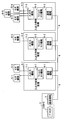
- FIG. 1 is a block diagram showing an overall configuration of a controller system according to Embodiment 1 of the present invention.
- the overall configuration of a controller system according to another embodiment described later is the same as the overall configuration of the controller system of FIG.
- the input / output control device 4-1 includes a controller 1 and input / output control devices 4-1, 4-2 and 4-3.
- input / output control device 4-1 to the input / output control device 4-3 may be simply referred to as “input / output control device 4”.
- the plurality of input / output control devices according to the present invention is not limited to the three input / output control devices 4, and may be two or more input / output control devices other than three.
- the controller 1 includes a processor 2 and a communication function 3.
- the processor 2 is composed of, for example, a CPU.
- the communication function 3 can communicate with the input / output control device 4 and here communicates with the input / output control device 4-1.
- the controller 1 is connected via the communication bus 6 so that it can communicate with the input / output control device 4-1.
- the input / output control device 4-1 is connected to the input / output control device 4-2 via the communication bus 6 so that the input / output control device 4-2 can communicate with the input / output control device 4-3.
- the plurality of input / output control devices 4 are connected in series so as to be communicable with the controller 1.
- the input / output control device 4-1 is connected to the sensor devices 5-1 and 5-2
- the input / output control device 4-2 is connected to the sensor device 5-3
- the input / output control device 4- 3 is connected to sensor devices 5-4, 5-5 and 5-6.
- each may be simply referred to as “sensor device 5”.
- the sensor device according to the present invention is not limited to the six sensor devices 5, and may be one or more sensor devices other than six.
- the sensor device 5 inputs / outputs sensor data from / to the outside of the sensor device 5.
- the input / output control device 4 can be connected to the sensor device 5 and inputs / outputs sensor data to / from the connected sensor device 5.
- the input / output control device 4-1 includes an input / output function 7-1, a one-shot timer function 8-1, and a communication function 9-1.
- the input / output control device 4-2 includes an input / output function 7-2, a one-shot timer function 8-2, and a communication function 9-2.
- the input / output control device 4-3 includes an input / output function 4-2. 7-3, a one-shot timer function 8-3, and a communication function 9-3.
- each may be simply referred to as “input / output function 7”.
- the one-shot timer functions 8-1 to 8-3 each may be simply referred to as “one-shot timer function 8”.
- communication function 9 each may be simply referred to as “communication function 9”.
- the input / output function 7 inputs and outputs data such as sensor data with the sensor device 5.
- the one-shot timer function 8 generates an interrupt when the counter counted after obtaining the activation request for the one-shot timer 12 from the controller 1 is equal to the one-shot timer activation counter described later.
- the communication function 9 transmits and receives data such as sensor data to and from the controller 1 and one input / output control device 4 or two input / output control devices 4.
- the one-shot timer 12 is a circuit that outputs a pulse signal for a predetermined time only once after the activation time is set and activated.
- the counter is a register used by software or hardware. Throughout the specification, the counter is a value calculated by counting time based on the frequency of each device. Throughout the specification, values or times that are compared by software or hardware are used to define intervals or times.
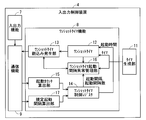
- FIG. 2 is a block diagram showing a configuration of the input / output control device 4 according to the first embodiment.
- one input / output control device 4 of interest among the plurality of input / output control devices 4 may be referred to as “own device”.
- the 2 includes a timer generation unit 11, a one-shot timer 12, a one-shot timer interrupt generation unit 13, a one-shot timer control register 14, and an activation counter calculation unit 15.
- the timer generation unit 11 has a common timer generation frequency for each input / output control device, and generates a trigger for periodically incrementing the count.
- the one-shot timer 12 periodically increments the one-shot timer count based on a trigger from the timer generation unit 11 when activated.
- the one-shot timer interrupt generation unit 13 generates a one-shot timer interrupt when the one-shot timer count is equal to the timer activation counter.
- the one-shot timer control register 14 stores parameters for controlling the operation of the input / output control device 4.
- the activation counter calculation unit 15 is the total of the sensor devices 5 that are targets to activate the one-shot timer 12 among the sensor devices 5 connected to the other input / output control devices 4 between the own device and the controller 1.
- the one-shot timer activation counter is calculated based on the number and the unit conversion coefficient obtained by converting the one-shot timer activation time based on the timer generation frequency.
- the calculation result of the activation counter calculation unit 15 is stored in the one-shot timer control register 14.
- the one-shot timer counter is a register indicating the number of times the clock signal has become valid after the one-shot timer is activated.
- the timer activation counter is a register for the one-shot timer to output a pulse signal when equal to the one-shot timer counter.
- the one-shot timer activation time indicates a common interval / time that does not depend on the frequency of the apparatus.
- the one-shot timer activation counter is a register that stores a value calculated using time as a counter based on the frequency of the apparatus.
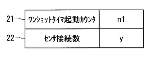
- FIG. 3 is a diagram showing parameters stored in the one-shot timer control register 14 according to the first embodiment.
- the one-shot timer control register 14 stores a timer start counter 21 and a sensor connection number 22 as parameters.
- the timer activation counter 21 is a counter that is compared with the one-shot timer count of the one-shot timer 12 in order to determine whether or not a one-shot timer interrupt should be generated.
- the sensor connection number 22 is the total of the sensor devices 5 that are targets for starting the one-shot timer 12 among the sensor devices 5 connected to the other input / output control devices 4 between the own device and the controller 1. Is a number.
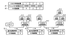
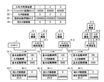
- FIG. 4 is a diagram for explaining processing of the controller system according to the first embodiment.
- the calculation of the following one-shot timer activation counter is performed by the activation counter calculation unit 15 of each of the input / output control devices 4-1 to 4-3.
- Initialization registration data 31-1 which is data for defining parameters of the one-shot timer control register 14 to the input / output control device 4-1.
- Initialization registration data 31-1 includes a basic activation time that is a predetermined time for activating a single one-shot timer 12, and the number of sensor connections.
- the basic activation time of the registration data 31-1 at initialization is “100”, and the number of sensor connections of the registration data 31-1 at initialization is “0”, which is an initial value.
- the input / output control device 4-1 calculates a one-shot timer start counter based on the number of sensor connections.
- the input / output control device 4-1 calculates a value obtained by basic start time + basic start time ⁇ number of connected sensors as a one-shot timer start counter, and the calculated one-shot timer start counter
- the received number of sensor connections is stored in the one-shot timer control register 14.
- the input / output control device 4-1 transmits initialization data 31-2 similar to the initialization data 31-1 to the input / output control device 4-2.
- the basic activation time of the initialization registration data 31-2 is “100”.
- the number of sensor connections in the initialization registration data 31-2 is “0” as the number of sensor connections in the initialization registration data 31-1, and the sensor devices 5-1 and 5 connected to the input / output control device 4-1.
- -2 is "2" with "2" added.
- the input / output control device 4-2 calculates a one-shot timer start counter based on the number of sensor connections.
- the input / output control device 4-2 calculates the one-shot timer start counter in the same manner as the calculation of the one-shot timer start counter by the input / output control device 4-1, and the calculated one-shot timer
- the activation counter and the number of received sensor connections are stored in the one-shot timer control register 14.
- the input / output control device 4-2 transmits initialization data 31-3 similar to the initialization data 31-1 to the input / output control device 4-3.
- the basic activation time of the initialization registration data 31-3 is “100”.
- the number of sensor connections in the registration data 31-3 at initialization is “2” as the number of sensor connections in the registration data 31-2 at initialization, and the “number of sensor connections” in the sensor device 5-3 connected to the input / output control device 4-2. “3” with “1” added.
- the input / output control device 4-3 calculates a one-shot timer start counter based on the number of connected sensors.
- the input / output control device 4-3 calculates the one-shot timer activation counter in the same manner as the calculation of the one-shot timer activation counter by the input / output control device 4-1, and the calculated one-shot timer
- the activation counter and the number of received sensor connections are stored in the one-shot timer control register 14.
- registration data 31-1 to 31-3 at initialization each may be simply referred to as “registration data 31 at initialization”.
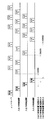
- FIG. 5 is a timing chart showing the timing for transmitting sensor data to the controller 1 by a one-shot timer interrupt in the controller system according to the first embodiment.
- 5 corresponds to the input / output control devices 4-1, 4-2, 4-3 in FIG. 1, and the input / output control device 1 start counter in FIG. This corresponds to the one-shot timer start counter of the input / output control device 4-1.
- 5 corresponds to the initialization registration data 31 described with reference to FIG. 4.
- the sensors 1, 2, 3, 4, 5, and 6 in FIG. It corresponds to the sensor data of 5-2, 5-3, 5-4, 5-5 and 5-6. These notations are used similarly in the subsequent timing charts.
- the initialization registration data 31 from the controller 1 is transmitted to the input / output control devices 4-1, 4-2, 4-3 in order, so that the input / output control device 4
- the one-shot timer start counters are sequentially set in the one-shot timer control registers 14 of -1, 4-2 and 4-3.
- the one-shot timer start counter of the input / output control device 4-1 When the one-shot timer start counter of the input / output control device 4-1 is set, the one-shot timer 12 of the input / output control device 4-1 starts. When the one-shot timer count becomes equal to the one-shot timer start counter (in this example, “100000”) of the input / output control device 4-1, the input / output control device 4-1 The sensor data 5-1 and 5-2 are transmitted to the controller 1 in order.
- the one-shot timer activation counter of the input / output control device 4-2 is set, the one-shot timer 12 of the input / output control device 4-2 is activated.
- the one-shot timer count becomes equal to the one-shot timer start counter (“300000” in this example) of the input / output control device 4-2, the input / output control device 4-2
- the sensor data 5-3 is transmitted to the controller 1 via the input / output control device 4-1.
- the one-shot timer start counter of the input / output control device 4-3 when the one-shot timer start counter of the input / output control device 4-3 is set, the one-shot timer 12 of the input / output control device 4-3 starts.
- the one-shot timer count becomes equal to the one-shot timer start counter (“400000” in this example) of the input / output control device 4-3, the input / output control device 4-3
- the sensor data 5-4, 5-5, and 5-6 are sequentially transmitted to the controller 1 via the input / output control devices 4-1 and 4-2.
- FIG. 6 is a flowchart showing a one-shot timer interrupt generation process in the input / output control device 4 according to the first embodiment. The processing of this flowchart is executed when a trigger is generated by the timer generation unit 11, in other words, when a trigger is received.
- step S1 the input / output control device 4 turns off the one-shot timer interrupt.
- step S2 the input / output control device 4 determines whether or not the one-shot timer 12 is currently activated. If it is determined that it has been started, the process proceeds to step S3. If it is determined that it has been stopped, the process proceeds to step S6.
- step S3 the one-shot timer 12 increments the one-shot timer count.
- step S4 the one-shot timer interrupt generation unit 13 determines whether or not the one-shot timer count is equal to the one-shot timer activation counter. If it is determined that they are equal, the process proceeds to step S5. If it is determined that they are not equal, the process of FIG. 6 ends.
- step S5 the one-shot timer interrupt generator 13 turns on the one-shot timer interrupt and generates a one-shot timer interrupt. Further, the input / output control device 4 stops activation of the one-shot timer 12. Thereafter, the process of FIG. 6 ends.
- step S6 the input / output control device 4 determines whether or not the activation request for the one-shot timer 12, such as the registration data 31 at initialization, has been acquired from the controller 1. If it is determined that it has been acquired, the process proceeds to step S7. If it is determined that it has not been acquired, the process of FIG. 6 ends.
- step S7 the input / output control device 4 resets the one-shot timer count to 0 and activates the one-shot timer 12. Thereafter, the process of FIG. 6 ends.
- each activation counter calculation unit 15 of the plurality of input / output control devices 4 calculates a one-shot timer activation counter based on the number of sensor connections. According to such a configuration, even if the timer is provided in the controller 1 and the controller 1 does not manage the time event queue, that is, does not manage the time for generating an interrupt, the controller 1 Can be obtained. For this reason, the load of the controller 1 can be suppressed. In addition, an improvement in the responsiveness of the controller system can be expected.
- the one-shot timer interrupt generation unit 13 generates a one-shot timer interrupt when the one-shot timer count is equal to the one-shot timer activation counter.
- the present invention is not limited to this example, and the one-shot timer interrupt generation unit 13 may generate a one-shot timer interrupt when the one-shot timer count is equal to or greater than the one-shot timer activation counter.
- the one-shot timer 12 periodically increments the one-shot timer count.
- the present invention is not limited to this example, and the one-shot timer 12 may periodically decrement the one-shot timer count in which the initial value is set to a relatively large value.
- the one-shot timer interrupt generator 13 may generate a one-shot timer interrupt when the difference between the initial value and the one-shot timer count is equal to or greater than the one-shot timer activation counter. That is, the one-shot timer interrupt generation unit 13 may be configured to generate a one-shot timer interrupt based on the one-shot timer count and the one-shot timer activation counter.
- FIG. 7 is a block diagram showing the configuration of the input / output control apparatus according to Embodiment 2 of the present invention.
- the same or similar constituent elements as those in the first embodiment are denoted by the same reference numerals, and different constituent elements will be mainly described.
- the one-shot timer function 8 in FIG. 7 includes a one-shot timer activation interval abnormality management unit 16 and a specified activation interval calculation unit 17 in addition to the one-shot timer function 8 according to the first embodiment in FIG.
- the one-shot timer activation interval abnormality management unit 16 defines the interval between the time when the one-shot timer 12 was activated last time and the time when the one-shot timer 12 is activated next time, that is, the activation interval of the one-shot timer 12. Detects whether or not it is more than the startup interval. Then, the one-shot timer activation interval abnormality management unit 16 notifies the controller 1 of the activation interval abnormality when the activation interval of the one-shot timer 12 is equal to or greater than the specified activation interval.
- the specified activation interval calculation unit 17 is defined based on the total number of sensor devices 5 that are the targets for starting the one-shot timer 12 among all the sensor devices 5 connected to the plurality of input / output control devices 1. Calculate the startup interval counter. The calculation result of the prescribed activation interval calculation unit 17 is stored in the one-shot timer control register 14. The specified activation interval calculation unit 17 is not necessarily provided in each of the plurality of input / output control devices 1, and may be provided in at least one of the plurality of input / output control devices 1.
- FIG. 8 is a diagram showing parameters stored in the one-shot timer control register 14 according to the second embodiment.
- the one-shot timer control register 14 according to the second embodiment stores a specified activation interval counter 23 and a total sensor connection number 24 in addition to the parameters shown in FIG.
- the prescribed activation interval counter 23 is a predefined counter for determining whether or not the activation interval of the one-shot timer 12 is abnormal.
- the total number of sensor connections 24 is the sensor device for which the one-shot timer 12 is activated among all the sensor devices 5-1 to 5-6 connected to the input / output control devices 4-1 to 4-3. Is the total number of That is, the total number of sensor connections 24 is the total number of sensor devices that are targets for starting the one-shot timer 12 among all the sensor devices 5 connected to the controller system.
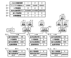
- FIG. 9 is a diagram for explaining processing of the controller system according to the second embodiment.
- the controller 1 transmits initialization data 31-1 to the input / output control device 4-1.
- the initialization registration data 31-1 according to the second embodiment includes a basic activation interval in addition to the initialization registration data 31-1 according to the first embodiment in FIG.
- the initialization registration data 31-2 and 31-3 according to the second embodiment further includes a basic activation interval.
- the basic activation interval of the initialization registration data 31-1 to 31-3 is “2000000”.
- the prescribed activation interval calculation unit 17 calculates a prescribed activation interval counter based on the total number of sensor connections.
- the specified activation interval calculation unit 17 is provided in the input / output control device 4-3 which is a termination device in the column of the input / output control devices 4-1 to 4-3, and the basic activation interval ⁇ A value obtained by the total number of sensor connections ⁇ unit conversion coefficient is calculated as a specified activation interval counter.
- the input / output control device 4-3 stores the calculated total sensor connection number and the specified activation interval counter in the one-shot timer control register 14 of the input / output control device 4-3. Further, the input / output control device 4-3 transmits the initialization return data 41-3 including the total number of sensor connections and the specified activation interval counter to the input / output control device 4-2.
- the input / output control device 4-2 stores the transmitted total number of sensor connections and the specified activation interval counter in the one-shot timer control register 14 of the input / output control device 4-2. Further, the input / output control device 4-2 transmits initialization return data 41-2 including the total number of sensor connections and the specified activation interval counter to the input / output control device 4-1.
- the input / output control device 4-1 stores the transmitted total number of sensor connections and the specified activation interval counter in the one-shot timer control register 14 of the input / output control device 4-1. Further, the input / output control device 4-1 transmits the initialization return data 41-1 including the total number of sensor connections and the prescribed activation interval counter to the controller 1.
- initialization return data 41 when the initialization return data 41-1 to 41-3 are not specified, each may be simply referred to as “initialization return data 41”.
- the one-shot timer activation interval abnormality management unit 16 of the input / output control device 4 notifies the controller 1 of the activation interval abnormality when the one-shot timer count exceeds the specified activation interval counter.
- FIG. 10 is a flowchart showing the calculation processing of the total number of connected sensors and the prescribed activation interval counter in the input / output control device 4 according to the second embodiment.
- step S11 when the input / output control device 4 receives the registration data 31 at initialization including the basic activation time, the number of sensor connections, and the basic activation interval, the input / output control device 4 is connected to the device at the received number of sensor connections.
- a value obtained by adding the number of sensor devices 5 is stored in the one-shot timer control register 14 of the own device as the number of sensor connections of the own device.
- step S12 the input / output control device 4 determines whether or not the own device is a termination device in the row of the plurality of input / output control devices 4. If it is determined that the device is not a terminal device, the process proceeds to step S13. If it is determined that the device is a terminal device, the process proceeds to step S14.
- step S ⁇ b> 13 the input / output control device 4 transmits the initialization registration data 31 including the calculated number of sensor connections and the received basic activation time and basic activation interval to the termination-side input / output control device 4. To do. Thereafter, the process of FIG. 10 ends.
- step S14 since the input / output control device 4 is a termination device, the calculated number of sensor connections is stored in the one-shot timer control register 14 of its own device as the total number of sensor connections. To do.
- the specified activation interval calculation unit 17 multiplies the basic activation interval, the total number of sensor connections, and the unit conversion coefficient, and stores the result in the one-shot timer control register 14 of its own apparatus as a specified activation interval counter.
- step S15 the input / output control device 4 transmits the initialization return data 41 including the total number of connected sensors and the specified activation interval counter to the input / output control device 4 on the controller 1 side or the controller 1. Thereafter, the process of FIG. 10 ends.
- the specified activation interval counter is calculated based on the total number of sensor connections. According to such a configuration, even if the total number of sensor connections is increased or decreased, the specified activation interval counter can be appropriately changed. As a result, it is possible to appropriately detect the activation interval abnormality.
- Embodiment 3 The configuration of the input / output control device according to Embodiment 3 of the present invention is the same as the configuration of the input / output control device according to Embodiment 2 of FIG.
- constituent elements that are the same as or similar to those in the second embodiment are denoted by the same reference numerals, and different constituent elements are mainly described.
- the one-shot timer activation interval abnormality management unit 16 determines whether or not the unit interval counter whose unit is a predetermined number of activation intervals of the one-shot timer 12 is equal to or greater than a specified activation interval counter. Is detected. Then, the one-shot timer activation interval abnormality management unit 16 notifies the controller 1 of the activation interval abnormality when the unit interval counter of the one-shot timer 12 is greater than or equal to the specified activation interval counter.
- the specified activation interval calculation unit 17 includes the total number of sensor devices 5 that are to be activated by the one-shot timer 12 among all the sensor devices 5 connected to the plurality of input / output control devices 1 and unit conversion coefficients. And the prescribed activation interval counter is calculated based on the above-described multiple times.
- the specified activation interval calculation unit 17 is not necessarily provided in each of the plurality of input / output control devices 1, and may be provided in at least one of the plurality of input / output control devices 1.
- FIG. 11 is a diagram showing parameters stored in the one-shot timer control register 14 according to the third embodiment.
- the one-shot timer control register 14 according to the third embodiment stores the activation interval number 25 in addition to the parameters shown in FIG.
- the activation interval number 25 indicates the above-described multiple times in the unit interval.
- FIG. 12 is a diagram for explaining processing of the controller system according to the third embodiment.
- the controller 1 transmits initialization data 31-1 to the input / output control device 4-1.
- the initialization registration data 31-1 according to the third embodiment includes the number of activation intervals in addition to the initialization registration data 31-1 according to the second embodiment in FIG.
- the initialization registration data 31-2 and 31-3 according to the third embodiment further includes the number of activation intervals.
- the activation interval number of the registration data 31-1 to 31-3 at initialization is “2”.
- the prescribed activation interval calculation unit 17 calculates a prescribed activation interval counter based on the total sensor connection number and the activation interval number.
- the input / output control device 4 stores the total number of connected sensors and the specified activation interval counter in the one-shot timer control register 14 of its own device. Then, the input / output control device 4 transmits the initialization return data 41 including the total number of sensor connections and the specified activation interval counter to the input / output control device 4 on the controller 1 side or the controller 1.
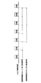
- FIG. 13 is a timing chart showing an interval for detecting a startup interval abnormality in the controller system according to the third embodiment and an interval for detecting a startup interval abnormality in the controller system according to the second embodiment.
- FIG. 13 shows the input / output control device 4-1, the same applies to the input / output control devices 4-2 and 4-3.
- the monitoring interval when there is no activation interval number in FIG. 13 means a monitoring interval when the activation interval number is 1, and corresponds to the detection interval of the activation interval abnormality in the second embodiment.
- the detection interval of the activation interval abnormality in the second embodiment corresponds to the activation interval for one time of the one-shot timer 12.
- the monitoring section when the number of activation intervals in FIG. 13 is 2 corresponds to the detection interval of the activation interval abnormality in the third embodiment.
- the detection interval of the activation interval abnormality in the third embodiment corresponds to the activation interval of two times of the one-shot timer 12, that is, the activation interval of the activation interval number.
- FIG. 14 is a flowchart showing a detection process of an abnormal start interval in the input / output control device 4 according to the third embodiment. The following description is based on the assumption that the trigger of the timer generation unit 11 has been received and the interrupt handler has already been started.
- step S21 the activation interval timer (not shown) of the input / output control device 4 increments the activation interval timer count.
- step S22 the one-shot timer activation interval abnormality management unit 16 determines whether the activation interval timer count matches the specified activation interval counter. If it is determined that they match, the process proceeds to step S23, and if it is determined that they do not match, the process proceeds to step S24.
- step S23 the one-shot timer activation interval abnormality management unit 16 activates a one-shot timer activation interval abnormality interrupt and notifies the controller 1 of the activation interval abnormality. Thereafter, the process of FIG. 14 ends.
- the one-shot timer activation interval abnormality management unit 16 determines whether or not the activation request for the one-shot timer 12 such as registration data 31 at initialization is acquired from the controller 1. judge. If it is determined that it has been acquired, the process proceeds to step S25. If it is determined that it has not been acquired, the process proceeds to step S26.
- step S25 the one-shot timer activation interval abnormality management unit 16 increments the activation count. Then, the process proceeds to step S26.
- step S26 the one-shot timer activation interval abnormality management unit 16 determines whether or not the activation count matches the activation interval number. If it is determined that they match, the process proceeds to step S27. If it is determined that they do not match, the process of FIG. 14 ends.
- step S27 the one-shot timer activation interval abnormality management unit 16 resets the activation count and the activation interval timer count to zero. Thereafter, the process of FIG. 14 ends.
- the specified activation interval counter is calculated based on the total number of sensor connections, the activation interval number, and the unit conversion coefficient. The effect of can be obtained.
- an activation interval abnormality can be detected.
- Embodiment 4 The configuration of the input / output control device according to Embodiment 4 of the present invention is the same as the configuration of the input / output control device according to Embodiment 2 of FIG.
- constituent elements that are the same as or similar to those in the third embodiment are denoted by the same reference numerals, and different constituent elements are mainly described.
- the one-shot timer activation interval abnormality management unit 16 includes a first mode for detecting an activation interval abnormality starting from one activation of the one-shot timer 12, and the number of activation intervals of the one-shot timer. And a second mode in which an activation interval abnormality is detected starting from the activation.
- the one-shot timer activation interval abnormality management unit 16 selectively implements the first mode and the second mode.
- the first mode will be described as a superposition mode
- the second mode will be described as a normal mode.
- FIG. 15 is a diagram showing parameters stored in the one-shot timer control register 14 according to the fourth embodiment.
- the one-shot timer control register 14 according to the fourth embodiment stores an operation mode 26 in addition to the parameters shown in FIG.
- the operation mode 26 indicates whether the control method for monitoring the activation interval of the one-shot timer is the normal mode or the overlap mode.
- the operation mode 26 is “0”, it may indicate that the control method is the normal mode, and when the operation mode 26 is “1”, the control method is the overlap mode. It is configured.
- FIG. 16 is a diagram for explaining processing of the controller system according to the fourth embodiment.
- the controller 1 transmits initialization data 31-1 to the input / output control device 4-1.
- the initialization registration data 31-1 according to the fourth embodiment includes an operation mode in addition to the initialization registration data 31-1 according to the third embodiment of FIG.
- the initialization registration data 31-2 and 31-3 according to the fourth embodiment further includes an operation mode.
- the operation mode of the registration data 31-1 to 31-3 at initialization is “overlapping mode”.
- the initialization registration data 31 from the controller 1 is sequentially transmitted to the input / output control devices 4-1, 4-2, 4-3, so that the input / output control devices 4-1, 4-2, In the 4-3 one-shot timer control register 14, the “overlapping mode” is set in order.
- FIG. 17 is a timing chart showing the intervals at which the activation interval abnormality is detected in the controller system according to the fourth embodiment.
- FIG. 17 shows the input / output control device 4-1, but the same applies to the input / output control devices 4-2 and 4-3.
- the number of activation intervals is “2”.
- the normal mode starting of the same number of activation intervals as the number of activation intervals of the one-shot timer 12 is used as a starting point, monitoring of the activation interval is started, and detection of an abnormal activation interval is performed.
- the overlap mode monitoring of all the activation intervals is started with one activation of the one-shot timer 12 as a starting point, and the activation interval abnormality is detected.
- FIG. 18 is a diagram showing the overlap mode activation interval management table. This overlap mode activation interval management table stores information for managing all activation intervals using the overlap mode.
- This table has the same number of records as the number of activation intervals.
- the timer number is a number indicating the ID of the record, and numbers are given in the order of 0, 1, 2,.
- the activation interval timer count is incremented to monitor the activation interval, while being reset at activation.
- the reset trigger is data for deciding how many times the activation request is received and resetting the activation interval timer count, and is a variable that is changed as the processing proceeds.
- the specified activation interval counter is the same as described above.
- the number of activation requests is the number of times an activation interval timer (not shown) provided in the input / output control device 4 has been activated so far, and is a variable that is changed as processing proceeds.
- FIG. 19 is a flowchart showing a detection process of a start interval abnormality when the overlap mode is applied in the input / output control device 4 according to the fourth embodiment. The following description is based on the assumption that the trigger of the timer generation unit 11 has been received and the interrupt handler has already been started.
- steps S31 to S38 described below is repeatedly executed by the same number as the number of activation intervals and consequently the number of timer numbers.
- the timer number compared in step S31 is changed so as to increase in order of 0, 1, 2,... Each time the flow of steps S31 to S38 is repeated.
- step S31 the input / output control device 4 determines whether the number of activation requests is larger than the timer number. If it is determined that the number of activation requests is greater than the timer number, the process proceeds to step S32. If it is determined that the number of activation requests is equal to or less than the timer number, the process of FIG. Thus, only when an activation request is received, the process proceeds to step S32 and each timer detects an abnormality.
- step S32 the activation interval timer (not shown) of the input / output control device 4 increments the activation interval timer count.
- step S33 the one-shot timer activation interval abnormality management unit 16 determines whether or not the activation interval timer count matches the specified activation interval counter. If it is determined that they match, the process proceeds to step S34, and if it is determined that they do not match, the process proceeds to step S35.
- step S34 the one-shot timer activation interval abnormality management unit 16 activates a one-shot timer activation interval abnormality interrupt and notifies the controller 1 of the activation interval abnormality. Thereafter, if the number of repetitions of the flow of steps S31 to S38 has not reached the number of activation intervals, the process returns to step S31, and if it has reached the number of activation intervals, the process of FIG.
- the one-shot timer activation interval abnormality management unit 16 determines whether or not the activation request for the one-shot timer 12 such as the registration data 31 at initialization is acquired from the controller 1. judge. If it is determined that it has been acquired, the process proceeds to step S36. If it is determined that it has not been acquired, the process proceeds to step S37.
- step S36 the one-shot timer activation interval abnormality management unit 16 increments the number of activation requests. Then, the process proceeds to step S37.
- step S37 the one-shot timer activation interval abnormality management unit 16 determines whether or not the number of activation requests matches the reset trigger. If it is determined that they match, the process proceeds to step S38. If it is determined that they do not match, the process returns to step S31 if the number of repetitions of the flow of steps S31 to S38 has not reached the number of activation intervals, and if the number of activation intervals has been reached, the process of FIG. finish.
- step S38 the one-shot timer activation interval abnormality management unit 16 resets the activation interval timer count to 0, and adds the activation interval number to the reset trigger. Thereafter, if the number of repetitions of the flow of steps S31 to S38 has not reached the number of activation intervals, the process returns to step S31, and if it has reached the number of activation intervals, the process of FIG.
- the overlap mode in which the activation interval abnormality can be detected every time the one-shot timer 12 is activated, and the activation interval of the one-shot timer 12 The normal mode capable of detecting the activation interval abnormality every number of activations is selectively performed. Thereby, the electric power used in a circuit can be reduced as needed.
- FIG. 20 is a block diagram showing the configuration of the input / output control apparatus according to Embodiment 5 of the present invention.
- constituent elements described in the fifth embodiment constituent elements that are the same as or similar to those in the fourth embodiment are denoted by the same reference numerals, and different constituent elements are mainly described.
- the one-shot timer 12 increments the one-shot timer count. Then, the one-shot timer prohibition / permission unit 18 controls permission / prohibition of increment of the one-shot timer count by controlling activation and stop of the one-shot timer 12.
- the present invention is not limited to this example.
- the one-shot timer 12 decrements, the one-shot timer prohibition / permission unit 18 controls the one-shot timer 12 to start and stop, thereby controlling the one-shot timer count. The decrement permission and prohibition may be controlled.
- the input / output control device 4 detects the start interval abnormality when all of the sensor devices 5 connected to the own device are not the targets for starting the one-shot timer 12. Ban.
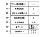
- FIG. 21 is a diagram showing parameters stored in the one-shot timer control register 14 according to the fifth embodiment.
- the one-shot timer control register 14 according to the fifth embodiment stores a timer enable 27 in addition to the parameters shown in FIG.
- the timer enable 27 indicates count-up of the one-shot timer 12 for each sensor device 5, that is, permission or prohibition of increment. Here, if the timer enable 27 is “0”, it indicates that activation and increment of the one-shot timer 12 are prohibited. If the timer enable 27 is “1”, activation and increment of the one-shot timer 12 are indicated. Indicates that is allowed.
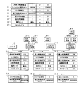
- FIG. 22 is a diagram for explaining processing of the controller system according to the fifth embodiment.
- the controller 1 transmits the initialization registration data 31-1 to the input / output control device 4-1.
- the initialization registration data 31-1 according to the fifth embodiment includes a timer enable in addition to the initialization registration data 31-1 according to the fourth embodiment in FIG.
- the initialization registration data 31-2 and 31-3 according to the fifth embodiment further includes a timer enable.
- the timer enable of the registration data 31-1 to 31-3 at the time of initialization is “1” for permitting activation of the one-shot timer 12 of the input / output control device 4-1, and the input / output control.
- 3-bit “101” in which “0” prohibiting activation of the one-shot timer 12 of the device 4-2 and “1” permitting activation of the one-shot timer 12 of the input / output control device 4-3 are arranged. It is.
- the input / output control device 4-1 when the initialization registration data 31-1 is transmitted from the controller 1 to the input / output control device 4-1, the input / output control device 4-1 enables the timer enable of the received initialization registration data 31-1. “1” and the number of sensor connections “0” are stored in the one-shot timer control register 14 of the own apparatus. Then, the input / output control device 4-1 transmits the initialization registration data 31-2 to the input / output control device 4-2.
- the sensor devices 5-1 and 5-2 connected to the input / output control device 4-1 are targets for starting the one-shot timer 12, that is, targets for counting by the one-shot timer 12. For this reason, the number of sensor connections in the registration data 31-2 at initialization is obtained by adding “2” of the sensor devices 5-1 and 5-2 to “0” of the number of sensor connections in the registration data 31-1 at initialization. Is "2".
- the input / output control device 4-2 transmits the received initialization registration data 31-2.
- the timer enable “0” is stored in the one-shot timer control register 14 of the device itself.
- the input / output control device 4-2 transmits initialization data 31-3 to the input / output control device 4-3. Since the timer enable of the input / output control device 4-2 is “0”, the sensor device 5-3 connected to the input / output control device 4-2 is not a target for starting the one-shot timer 12. For this reason, the number of sensor connections in the registration data 31-3 at initialization remains “2” as the number of sensor connections in the registration data 31-2 at initialization without adding “1” of the sensor device 5-3. It becomes.
- the input / output control device 4-3 stores the received initialization registration data 31-3.
- the timer enable “1” and the sensor connection number “2” are stored in the one-shot timer control register 14 of the own apparatus. Since the input / output control device 4-3 is a terminal device, the sensor device 5-4 connected to the own device is set to “2” as the number of sensor connections in the received initialization registration data 31-3. “5” obtained by adding “3” of 5-5 and 5-6 is stored in the one-shot timer control register 14 of the own apparatus as the total number of sensor connections. This total sensor connection number is transmitted as the return data 41 at the time of initialization as described in the second embodiment.
- FIG. 23 is a timing chart showing the timing at which sensor data is transmitted to the controller 1 by a one-shot timer interrupt in the controller system according to the fifth embodiment.
- initialization not described in FIG. 5 corresponds to the return data upon initialization in FIG.
- the one-shot timer 12 is not activated for the sensor device 5-3 of the input / output control device 4-2. For this reason, the sensor data of the sensor device 5-3 is not transmitted from the input / output control device 4-2 to the controller 1 via the input / output control device 4-1.
- FIG. 24 is a flowchart showing a one-shot timer interrupt generation process in the input / output control device 4 according to the fifth embodiment.
- the processing of this flowchart is executed when a trigger is generated by the timer generation unit 11, in other words, when a trigger is received.
- the process of FIG. 24 is obtained by adding step S41 and changing step S5 to step S42 in the process of FIG. For this reason, the description of the processes in FIG. 24 other than steps S41 and S42 will be omitted as appropriate.
- step S41 the one-shot timer prohibition and permission unit 18 determines whether or not the timer enable is “1”, that is, whether or not the one-shot timer 12 is allowed to start and increment. If it is determined that the timer enable is “1”, the process proceeds to step S1. If it is determined that the timer enable is “0”, the process of FIG. 24 ends.
- step S4 If it is determined in step S4 from step S1 through steps S2 and S3 that the one-shot timer count is equal to the one-shot timer activation counter, the process proceeds to step S42.
- step S42 the one-shot timer interrupt generator 13 turns on the one-shot timer interrupt and generates a one-shot timer interrupt. Further, the input / output control device 4 stops starting the one-shot timer 12 and resets the one-shot timer count to zero. Thereafter, the process of FIG.
- FIG. 25 is a flowchart showing a start interval abnormality detection process in the input / output control device 4 according to the fifth embodiment. Note that the process of FIG. 25 is obtained by adding step S51 to the process of FIG. 19 of the fourth embodiment using the overlap mode. For this reason, description of processes other than step S51 in the process of FIG. 25 is omitted as appropriate.
- step S51 the input / output control device 4 determines whether or not the timer enable is “1”, that is, whether or not the one-shot timer 12 is allowed to start and increment. If it is determined that the timer enable is “1”, the trigger of the timer generation unit 11 is received and the interrupt handler has already been started, and then the process proceeds to step S31. Thereafter, processing similar to that in the fourth embodiment in FIG. 19 is performed. On the other hand, if it is determined that the timer enable is “0”, the processing in FIG. 25 ends.
- the one-shot timer 12 of only the necessary input / output control device 4 can be started. As a result, unnecessary sensor data need not be collected and transmitted, and the load on the controller 1 can be suppressed.
- Embodiment 6 The configuration of the input / output control device according to Embodiment 6 of the present invention is the same as the configuration of the input / output control device according to Embodiment 5 of FIG.
- the same or similar constituent elements as those in the fifth embodiment are denoted by the same reference numerals, and different constituent elements will be mainly described.
- the input / output control device 4 permits and prohibits the detection of the activation interval abnormality when the sensor device 5 connected to the own device is a target for starting the one-shot timer 12. It is possible to control.
- FIG. 26 is a diagram showing parameters stored in the one-shot timer control register 14 according to the sixth embodiment.
- the one-shot timer control register 14 according to the sixth embodiment stores a start interval enable 28 in addition to the parameters shown in FIG.
- the start interval enable 28 indicates permission and prohibition of detection of the start interval abnormality, and notification of the start interval abnormality to the controller 1 and non-notification.
- the start interval enable 28 is “0”, it indicates that detection of the start interval abnormality is prohibited.
- the start interval enable 28 is “1”, detection of the start interval abnormality is permitted. Indicates that
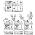
- FIG. 27 is a diagram for explaining processing of the controller system according to the sixth embodiment.
- the controller 1 transmits initialization data 31-1 to the input / output control device 4-1.
- the initialization registration data 31-1 according to the sixth embodiment includes a start interval enable in addition to the initialization registration data 31-1 according to the fifth embodiment of FIG.
- the initialization registration data 31-2 and 31-3 according to the sixth embodiment further include a start interval enable.
- the activation interval enable of the registration data 31-1 to 31-3 at the time of initialization is “0” prohibiting the detection of abnormality in the activation interval of the input / output control device 4-1, and the input / output control.
- This is a 3-bit “001” in which “1” that permits detection of the startup interval abnormality of the device 4-2 and “1” that allows detection of the startup interval abnormality of the input / output control device 4-3 are arranged. .
- the initialization registration data 31 from the controller 1 is sequentially transmitted to the input / output control devices 4-1, 4-2 and 4-3, thereby controlling the one-shot timer of the input / output control device 4-1.
- “0” is set as the activation interval enable 28 in the register 14
- “1” is set as the activation interval enable 28 in the one-shot timer control register 14 of the input / output control devices 4-2 and 4-3.
- the input / output control device 4-1 does not detect the start interval abnormality because the start interval abnormality is prohibited from being detected by the start interval enable.
- the input / output control device 4-2 is not allowed to detect the start interval abnormality because the start interval is permitted to be detected by the start interval enable but the start of the one-shot timer 12 is prohibited by the timer enable. .
- the input / output control device 4-3 detects the activation interval abnormality because the activation interval is permitted to be detected by the activation interval and the one-shot timer 12 is permitted to be activated by the timer enable.
- FIG. 28 is a flowchart showing detection processing for an abnormal start interval in the input / output control device 4 according to the sixth embodiment.
- the process of FIG. 28 is obtained by adding steps S51 and S61 to the process of FIG. 19 of the fourth embodiment using the overlap mode. For this reason, the description of the processes in FIG. 28 other than steps S51 and S61 will be omitted as appropriate.
- step S51 the input / output control device 4 determines whether or not the timer enable is “1”, that is, whether or not the one-shot timer 12 is allowed to start and increment. If it is determined that the timer enable is “1”, the process proceeds to step S61. If it is determined that the timer enable is “0”, the process of FIG. 28 ends.
- step S61 the input / output control device 4 determines whether or not the activation interval enable is “1”, that is, whether or not detection of the activation interval abnormality is permitted. If it is determined that the activation interval enable is “1”, the trigger of the timer generation unit 11 is received and the interrupt handler has already been activated, and then the process proceeds to step S31. Thereafter, processing similar to that in the fourth embodiment in FIG. 19 is performed. On the other hand, if it is determined that the activation interval enable is “0”, the processing in FIG. 28 ends.
- the controller system even if the sensor device 5 is a target for starting the one-shot timer 12, it controls the permission and prohibition of detection of the start interval abnormality. Thus, it is possible to detect the start interval abnormality of only the necessary input / output control device 4. As a result, it is possible to further enhance the effect that it is not necessary to detect and transmit an unnecessary activation interval abnormality, and the load on the controller 1 can be suppressed.
- controller 4-1 to 4-3 input / output control device, 5-1 to 5-6 sensor device, 12 one-shot timer, 13 one-shot timer interrupt generation unit, 15 activation counter calculation unit, 16 one-shot timer activation interval Anomaly management part, 17 Specified start interval calculation part, 18 One shot timer prohibition and permission part.
Landscapes
- Engineering & Computer Science (AREA)
- Physics & Mathematics (AREA)
- General Physics & Mathematics (AREA)
- Theoretical Computer Science (AREA)
- General Engineering & Computer Science (AREA)
- Automation & Control Theory (AREA)
- Software Systems (AREA)
- Computer Hardware Design (AREA)
- Programmable Controllers (AREA)
- Debugging And Monitoring (AREA)
Abstract
La présente invention a pour but de fournir une technologie capable de réduire rapidement une charge sur un dispositif de commande. Le système de commande comprend un dispositif de commande et une pluralité d'unités de commande d'E/S qui sont connectées en série au dispositif de commande de manière à pouvoir communiquer avec celui-ci et qui sont chacune individuellement capables de se connecter à des dispositifs de capteur. Chaque unité de commande d'E/S calcule un compteur d'activation de minuterie monostable sur la base, parmi les capteurs connectés aux autres unités de commande d'E/S entre cette unité de commande d'E/S et le dispositif de commande, du nombre total de dispositifs de capteur pour lesquels la minuterie monostable doit être activée.
Priority Applications (4)
| Application Number | Priority Date | Filing Date | Title |
|---|---|---|---|
| JP2018518074A JP6594533B2 (ja) | 2016-05-17 | 2017-01-26 | コントローラシステム |
| DE112017002556.7T DE112017002556B4 (de) | 2016-05-17 | 2017-01-26 | Steuerungssystem |
| US16/094,612 US10935949B2 (en) | 2016-05-17 | 2017-01-26 | Controller system |
| CN201780029386.0A CN109074046B (zh) | 2016-05-17 | 2017-01-26 | 控制器系统 |
Applications Claiming Priority (2)
| Application Number | Priority Date | Filing Date | Title |
|---|---|---|---|
| JP2016-098938 | 2016-05-17 | ||
| JP2016098938 | 2016-05-17 |
Publications (1)
| Publication Number | Publication Date |
|---|---|
| WO2017199469A1 true WO2017199469A1 (fr) | 2017-11-23 |
Family
ID=60325805
Family Applications (1)
| Application Number | Title | Priority Date | Filing Date |
|---|---|---|---|
| PCT/JP2017/002707 WO2017199469A1 (fr) | 2016-05-17 | 2017-01-26 | Système de dispositif de commande |
Country Status (5)
| Country | Link |
|---|---|
| US (1) | US10935949B2 (fr) |
| JP (1) | JP6594533B2 (fr) |
| CN (1) | CN109074046B (fr) |
| DE (1) | DE112017002556B4 (fr) |
| WO (1) | WO2017199469A1 (fr) |
Cited By (1)
| Publication number | Priority date | Publication date | Assignee | Title |
|---|---|---|---|---|
| CN108333969A (zh) * | 2018-02-12 | 2018-07-27 | 凯立自动化有限公司 | 串列式信号传输控制模块 |
Families Citing this family (1)
| Publication number | Priority date | Publication date | Assignee | Title |
|---|---|---|---|---|
| JP1710763S (ja) * | 2021-07-21 | 2022-03-25 | プログラマブルコントローラ用メモリーカードリーダー |
Citations (5)
| Publication number | Priority date | Publication date | Assignee | Title |
|---|---|---|---|---|
| JPS6349855A (ja) * | 1986-08-18 | 1988-03-02 | Sansha Electric Mfg Co Ltd | Cpuの割込み周期異常検出装置 |
| JPH0397041A (ja) * | 1989-09-11 | 1991-04-23 | Nec Corp | 割込信号監視回路 |
| JPH09146796A (ja) * | 1995-11-20 | 1997-06-06 | Hitachi Ltd | ハードウェア周期割込み回路の故障回復方法 |
| JP2006215873A (ja) * | 2005-02-04 | 2006-08-17 | Toshiba Corp | 制御装置、情報処理装置、及び転送処理方法 |
| JP2014160367A (ja) * | 2013-02-20 | 2014-09-04 | Mitsubishi Electric Corp | 演算処理装置 |
Family Cites Families (17)
| Publication number | Priority date | Publication date | Assignee | Title |
|---|---|---|---|---|
| US4124285A (en) | 1977-05-23 | 1978-11-07 | Levi Strauss & Co. | Marker projector system |
| CN1010621B (zh) * | 1986-09-06 | 1990-11-28 | 福建省机械科学研究院 | 多功能可编程时间控制器 |
| EP0477986B1 (fr) * | 1990-09-28 | 1996-11-20 | Isuzu Motors Limited | Système de détection d'image pour voiture |
| JPH05307617A (ja) | 1992-04-28 | 1993-11-19 | Mitsubishi Electric Corp | 半導体装置 |
| EP0636955B1 (fr) * | 1993-07-26 | 1998-11-04 | Hitachi, Ltd. | Unité de contrÔle pour véhicule et son système de contrÔle total |
| JPH0887752A (ja) * | 1994-09-14 | 1996-04-02 | Canon Inc | 光学的情報記録再生装置 |
| EP0704642B1 (fr) * | 1994-09-30 | 1999-07-21 | Mazda Motor Corporation | Système de commande de transmission automatique |
| US5911083A (en) * | 1996-12-27 | 1999-06-08 | Unisys Corporation | Programmable processor execution rate controller |
| EP1421704B1 (fr) * | 2001-08-29 | 2007-11-14 | Analog Devices, Inc. | Procedes et appareil pour controle d'horloge et d'alimentation dans des systemes sans fil |
| CA2418612C (fr) * | 2002-12-06 | 2005-12-27 | Marian Gavrila | Systeme hybride terminal de communication - alarme |
| DE10326542B4 (de) * | 2003-06-12 | 2016-12-08 | Siemens Aktiengesellschaft | Betriebsverfahren und Steuerungsprogramm für eine Zentraleinheit eines Automatisierungssystems sowie Zentraleinheit eines Automatisierungssystems und Automatisierungssystem selbst |
| US7986287B2 (en) * | 2005-08-26 | 2011-07-26 | Semiconductor Energy Laboratory Co., Ltd. | Display device and method of driving the same |
| JP4851855B2 (ja) * | 2006-06-09 | 2012-01-11 | 株式会社日立製作所 | 作業実績収集システム |
| EP2513792B1 (fr) * | 2009-12-17 | 2016-08-17 | Intel Corporation | Modération d'interruption en coopération pour un environnement de virtualisation |
| US8914551B2 (en) * | 2013-04-09 | 2014-12-16 | Analog Devices, Inc. | Sensor polling unit for microprocessor integration |
| JP2016031274A (ja) * | 2014-07-29 | 2016-03-07 | 日本電気株式会社 | 抵抗変化素子を用いたデジタル温度センサ及びコントローラ |
| EP3205949B1 (fr) * | 2014-10-10 | 2021-03-10 | Mitsubishi Electric Corporation | Dispositif de diagnostic d'économie d'énergie, procédé de diagnostic d'économie d'énergie et programme |
-
2017
- 2017-01-26 JP JP2018518074A patent/JP6594533B2/ja active Active
- 2017-01-26 CN CN201780029386.0A patent/CN109074046B/zh active Active
- 2017-01-26 US US16/094,612 patent/US10935949B2/en active Active
- 2017-01-26 WO PCT/JP2017/002707 patent/WO2017199469A1/fr active Application Filing
- 2017-01-26 DE DE112017002556.7T patent/DE112017002556B4/de active Active
Patent Citations (5)
| Publication number | Priority date | Publication date | Assignee | Title |
|---|---|---|---|---|
| JPS6349855A (ja) * | 1986-08-18 | 1988-03-02 | Sansha Electric Mfg Co Ltd | Cpuの割込み周期異常検出装置 |
| JPH0397041A (ja) * | 1989-09-11 | 1991-04-23 | Nec Corp | 割込信号監視回路 |
| JPH09146796A (ja) * | 1995-11-20 | 1997-06-06 | Hitachi Ltd | ハードウェア周期割込み回路の故障回復方法 |
| JP2006215873A (ja) * | 2005-02-04 | 2006-08-17 | Toshiba Corp | 制御装置、情報処理装置、及び転送処理方法 |
| JP2014160367A (ja) * | 2013-02-20 | 2014-09-04 | Mitsubishi Electric Corp | 演算処理装置 |
Cited By (1)
| Publication number | Priority date | Publication date | Assignee | Title |
|---|---|---|---|---|
| CN108333969A (zh) * | 2018-02-12 | 2018-07-27 | 凯立自动化有限公司 | 串列式信号传输控制模块 |
Also Published As
| Publication number | Publication date |
|---|---|
| US10935949B2 (en) | 2021-03-02 |
| CN109074046A (zh) | 2018-12-21 |
| JP6594533B2 (ja) | 2019-10-23 |
| DE112017002556B4 (de) | 2024-03-28 |
| CN109074046B (zh) | 2021-07-13 |
| US20190129370A1 (en) | 2019-05-02 |
| JPWO2017199469A1 (ja) | 2018-08-09 |
| DE112017002556T5 (de) | 2019-01-31 |
Similar Documents
| Publication | Publication Date | Title |
|---|---|---|
| JP5176813B2 (ja) | 冷却ファンの故障診断システム、故障診断装置、故障診断方法、故障診断プログラムおよび冷却装置 | |
| JP6594533B2 (ja) | コントローラシステム | |
| WO2013137425A1 (fr) | Circuit de surveillance d'anomalies dans une ecu | |
| JP2017208108A (ja) | 車載用電子機器の制御装置及び制御方法 | |
| JPWO2016047576A1 (ja) | 車載用電子機器の制御装置及び制御方法 | |
| KR101646210B1 (ko) | 기능 안전성을 고려한 모터 제어 시스템 | |
| JP2008532125A (ja) | プロセス実行を監視するための方法および装置 | |
| JP2019008787A5 (ja) | 2つの制御ループを制御するデカップラ、方法及びシステム | |
| US7424641B2 (en) | Control system and method for validating operation of the control system | |
| JP6246447B1 (ja) | コントローラシステム | |
| JP6502211B2 (ja) | 車両制御装置 | |
| JP2010282352A (ja) | Dma転送制御装置 | |
| KR101988723B1 (ko) | Mcu 동작 감시 시스템 및 제어방법 | |
| KR101713572B1 (ko) | 자동차 | |
| JP6925954B2 (ja) | 車両制御装置 | |
| JP5916785B2 (ja) | 送信アンテナをグループ毎に駆動制御する磁気共鳴設備およびその動作方法 | |
| JP2015112962A (ja) | 情報処理装置 | |
| JP2007283788A (ja) | 車両用電子制御装置 | |
| JP2012196071A (ja) | 電力変換器 | |
| JP2014146222A (ja) | 車両用マイクロコンピュータ装置 | |
| JP2015219896A (ja) | 複数の演算サーバを備えるクラウド制御システム、その制御プログラムのスケジューリング方法、及び演算サーバの冗長化方法 | |
| TWI833975B (zh) | 狀態管理系統及狀態管理方法 | |
| JP6132097B2 (ja) | 測定システムおよび測定方法 | |
| JP6960531B2 (ja) | エンジン制御装置及びエンジン制御方法 | |
| KR20190036104A (ko) | 마이컴 감시 장치 및 그 제어 방법 |
Legal Events
| Date | Code | Title | Description |
|---|---|---|---|
| ENP | Entry into the national phase |
Ref document number: 2018518074 Country of ref document: JP Kind code of ref document: A |
|
| 121 | Ep: the epo has been informed by wipo that ep was designated in this application |
Ref document number: 17798907 Country of ref document: EP Kind code of ref document: A1 |
|
| 122 | Ep: pct application non-entry in european phase |
Ref document number: 17798907 Country of ref document: EP Kind code of ref document: A1 |