WO2017199373A1 - 空気調和機 - Google Patents
空気調和機 Download PDFInfo
- Publication number
- WO2017199373A1 WO2017199373A1 PCT/JP2016/064749 JP2016064749W WO2017199373A1 WO 2017199373 A1 WO2017199373 A1 WO 2017199373A1 JP 2016064749 W JP2016064749 W JP 2016064749W WO 2017199373 A1 WO2017199373 A1 WO 2017199373A1
- Authority
- WO
- WIPO (PCT)
- Prior art keywords
- unit
- detection sensor
- indoor unit
- remote controller
- control unit
- Prior art date
Links
Images


Classifications
-
- F—MECHANICAL ENGINEERING; LIGHTING; HEATING; WEAPONS; BLASTING
- F24—HEATING; RANGES; VENTILATING
- F24F—AIR-CONDITIONING; AIR-HUMIDIFICATION; VENTILATION; USE OF AIR CURRENTS FOR SCREENING
- F24F11/00—Control or safety arrangements
- F24F11/89—Arrangement or mounting of control or safety devices
-
- G—PHYSICS
- G05—CONTROLLING; REGULATING
- G05B—CONTROL OR REGULATING SYSTEMS IN GENERAL; FUNCTIONAL ELEMENTS OF SUCH SYSTEMS; MONITORING OR TESTING ARRANGEMENTS FOR SUCH SYSTEMS OR ELEMENTS
- G05B23/00—Testing or monitoring of control systems or parts thereof
- G05B23/02—Electric testing or monitoring
- G05B23/0205—Electric testing or monitoring by means of a monitoring system capable of detecting and responding to faults
- G05B23/0259—Electric testing or monitoring by means of a monitoring system capable of detecting and responding to faults characterized by the response to fault detection
- G05B23/0267—Fault communication, e.g. human machine interface [HMI]
-
- F—MECHANICAL ENGINEERING; LIGHTING; HEATING; WEAPONS; BLASTING
- F24—HEATING; RANGES; VENTILATING
- F24F—AIR-CONDITIONING; AIR-HUMIDIFICATION; VENTILATION; USE OF AIR CURRENTS FOR SCREENING
- F24F11/00—Control or safety arrangements
- F24F11/30—Control or safety arrangements for purposes related to the operation of the system, e.g. for safety or monitoring
- F24F11/32—Responding to malfunctions or emergencies
- F24F11/36—Responding to malfunctions or emergencies to leakage of heat-exchange fluid
-
- F—MECHANICAL ENGINEERING; LIGHTING; HEATING; WEAPONS; BLASTING
- F24—HEATING; RANGES; VENTILATING
- F24F—AIR-CONDITIONING; AIR-HUMIDIFICATION; VENTILATION; USE OF AIR CURRENTS FOR SCREENING
- F24F11/00—Control or safety arrangements
- F24F11/30—Control or safety arrangements for purposes related to the operation of the system, e.g. for safety or monitoring
- F24F11/49—Control or safety arrangements for purposes related to the operation of the system, e.g. for safety or monitoring ensuring correct operation, e.g. by trial operation or configuration checks
-
- F—MECHANICAL ENGINEERING; LIGHTING; HEATING; WEAPONS; BLASTING
- F24—HEATING; RANGES; VENTILATING
- F24F—AIR-CONDITIONING; AIR-HUMIDIFICATION; VENTILATION; USE OF AIR CURRENTS FOR SCREENING
- F24F11/00—Control or safety arrangements
- F24F11/50—Control or safety arrangements characterised by user interfaces or communication
- F24F11/52—Indication arrangements, e.g. displays
-
- F—MECHANICAL ENGINEERING; LIGHTING; HEATING; WEAPONS; BLASTING
- F24—HEATING; RANGES; VENTILATING
- F24F—AIR-CONDITIONING; AIR-HUMIDIFICATION; VENTILATION; USE OF AIR CURRENTS FOR SCREENING
- F24F11/00—Control or safety arrangements
- F24F11/50—Control or safety arrangements characterised by user interfaces or communication
- F24F11/56—Remote control
-
- G—PHYSICS
- G05—CONTROLLING; REGULATING
- G05B—CONTROL OR REGULATING SYSTEMS IN GENERAL; FUNCTIONAL ELEMENTS OF SUCH SYSTEMS; MONITORING OR TESTING ARRANGEMENTS FOR SUCH SYSTEMS OR ELEMENTS
- G05B19/00—Programme-control systems
- G05B19/02—Programme-control systems electric
- G05B19/04—Programme control other than numerical control, i.e. in sequence controllers or logic controllers
- G05B19/042—Programme control other than numerical control, i.e. in sequence controllers or logic controllers using digital processors
- G05B19/0423—Input/output
-
- G—PHYSICS
- G05—CONTROLLING; REGULATING
- G05B—CONTROL OR REGULATING SYSTEMS IN GENERAL; FUNCTIONAL ELEMENTS OF SUCH SYSTEMS; MONITORING OR TESTING ARRANGEMENTS FOR SUCH SYSTEMS OR ELEMENTS
- G05B2219/00—Program-control systems
- G05B2219/20—Pc systems
- G05B2219/26—Pc applications
- G05B2219/2614—HVAC, heating, ventillation, climate control
Definitions
- the present invention relates to an air conditioner that performs air conditioning using a refrigerant.
- Patent Document 1 discloses an air conditioner that transmits an abnormality content and data relating to a method for dealing with the occurring abnormality from an indoor unit to a remote controller when the abnormality occurs.
- the remote controller may be referred to as a remote controller.
- refrigerant leakage detection may be detected using a refrigerant leakage detection sensor.
- some of the sensors that detect the leakage of the refrigerant may deteriorate the detection performance of the refrigerant leakage depending on the life.
- the detection performance of the refrigerant leakage is lowered, the refrigerant leakage may not be detected accurately, and the reliability of the air conditioner refrigerant leakage detection is lowered.
- the present invention has been made in view of the above, and an object of the present invention is to obtain an air conditioner that can maintain the refrigerant leak detection performance of the refrigerant leak detection sensor in a normal state and has high reliability of refrigerant leak detection.
- an air conditioner includes an indoor unit arranged indoors and an outdoor unit in which refrigerant is circulated between the indoor units arranged outdoors. And a remote controller that is communicably connected to the indoor unit, and a refrigerant leakage detection sensor that detects refrigerant leakage.
- the indoor unit includes an indoor unit control unit that controls the operation of the indoor unit, and the remote controller includes a remote controller control unit that controls the operation of the remote controller, and a display unit that displays various types of information in the remote controller.
- the indoor unit control unit determines that the necessity for replacement of the refrigerant leakage detection sensor has been detected, the indoor unit control unit performs control for transmitting replacement time notification information for instructing notification of the necessity for replacement of the refrigerant leakage detection sensor to the remote controller. Do.
- the remote controller control unit performs control to display a message notifying the necessity of replacement of the refrigerant leakage detection sensor on the display unit based on the replacement time notification information.
- the air conditioner according to the present invention can maintain the refrigerant leak detection performance of the refrigerant leak detection sensor in a normal state, and has an effect of obtaining an air conditioner with high reliability of refrigerant leak detection.
- the schematic diagram which shows the structure of the air conditioner in Embodiment 1 of this invention.
- the principal part functional block diagram of the air conditioner in Embodiment 1 of this invention The figure which shows an example of the hardware constitutions of the processing circuit in Embodiment 1 of this invention
- the figure which shows an example of the external appearance structure of the remote control of the air conditioner in Embodiment 1 of this invention The figure which shows an example of the message which notifies the necessity of replacement
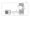
- FIG. 1 is a schematic diagram showing a configuration of an air conditioner 1 according to Embodiment 1 of the present invention.
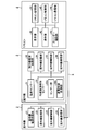
- FIG. 2 is a main part functional block diagram of the air conditioner 1 according to Embodiment 1 of the present invention.
- the air conditioner 1 according to the first embodiment includes an outdoor unit 2 arranged outdoors, an indoor unit 3 arranged indoors, and a remote controller 4 for remotely controlling the operation of the air conditioner 1.
- the outdoor unit 2 and the indoor unit 3 are connected by a refrigerant pipe 5 and an internal / external communication line 6, and a refrigerant for performing heat exchange flows through the refrigerant pipe 5.
- the air conditioner 1 forms one complete refrigeration cycle with the outdoor unit 2 and the indoor unit 3.
- the air conditioner 1 uses a refrigerant that circulates between the outdoor unit 2 and the indoor unit 3 through the refrigerant pipe 5 to transfer heat between indoor air and outdoor air that are air-conditioning target spaces.
- a refrigeration cycle mechanism including a blower fan and a compressor is omitted.
- the outdoor unit 2 has, as main components, various types of information necessary for air conditioning by the outdoor unit power supply circuit unit 21 that generates a control power source for operating each component in the outdoor unit 2 and the air conditioner 1.
- the outdoor unit storage unit 22 for storing the air conditioner, the outdoor unit control unit 23 for controlling the operation of the outdoor unit 2 by controlling each component in the outdoor unit 2 in order to perform air conditioning by the air conditioner 1, and the indoor unit 3
- an outdoor unit communication unit 24 that communicates information with the indoor unit communication unit 36 of the outdoor unit.
- the components of the outdoor unit 2 can exchange information with each other.
- the outdoor unit control unit 23 is realized, for example, as a processing circuit having a hardware configuration shown in FIG.
- FIG. 3 is a diagram illustrating an example of a hardware configuration of the processing circuit according to the first embodiment of the present invention.
- each component configuring the outdoor unit control unit 23 executes a program stored in the memory 102 by the processor 101. This is realized.
- a plurality of processors and a plurality of memories may cooperate to realize the above function.
- a part of the functions of the outdoor unit control unit 23 may be mounted as an electronic circuit, and the other parts may be realized using the processor 101 and the memory 102.
- the outdoor unit communication unit 24 may be configured to be realized by the processor 101 executing a program stored in the memory 102. Further, the processor and memory for realizing the outdoor unit communication unit 24 may be the same as the processor and memory for realizing the outdoor unit control unit 23, or may be another processor and memory.
- the indoor unit 3 includes, as a main configuration, a temperature sensor 31 that is an indoor temperature detection unit that detects various temperatures necessary for air conditioning processing in the air conditioner 1 such as the temperature of the room in which the indoor unit 3 is disposed and the temperature of the piping. Necessary for air-conditioning processing in the air conditioner 1, a refrigerant leak detection sensor 32 that detects refrigerant leakage, an indoor unit power supply circuit unit 33 that generates a control power source for operating each component in the indoor unit 3 An indoor unit storage unit 34 that stores various types of information, an indoor unit control unit 35 that controls the operation of the indoor unit 3 by controlling each component in the indoor unit 3 in order to perform air conditioning by the air conditioner 1, And an indoor unit communication unit 36 that communicates information with the remote controller 4.
- a temperature sensor 31 that is an indoor temperature detection unit that detects various temperatures necessary for air conditioning processing in the air conditioner 1 such as the temperature of the room in which the indoor unit 3 is disposed and the temperature of the piping.
- a refrigerant leak detection sensor 32 that detect
- the refrigerant leakage detection sensor 32 includes a sensor unit 32a that detects refrigerant leakage, an energization time measurement unit 32b that measures the time during which the refrigerant leakage detection sensor 32 is energized from the indoor unit power supply circuit unit 33 of the indoor unit 3, Is provided.
- the refrigerant leak detection sensor 32 is a semiconductor type gas sensor.
- the refrigerant leak detection sensor 32 is not limited to a semiconductor gas sensor, and may be a gas sensor of another detection method such as an infrared gas sensor.
- the refrigerant leakage detection sensor 32 deteriorates the detection performance in detecting refrigerant leakage according to the energization time. For this reason, the energization time measurement unit 32b measures the energization time of the refrigerant leak detection sensor 32 in order to inform the user of the replacement time before the deterioration of the detection accuracy in the detection of the refrigerant leak occurs. In order to notify the replacement time when the time elapses, the indoor unit control unit 35 is notified accordingly.
- the replacement here includes the meaning of repair.
- the indoor unit power supply circuit unit 33 is connected to a commercial AC power supply, which is an external power supply (not shown), by a power supply line.
- the indoor unit power supply circuit unit 33 generates a control power source for operating each component in the indoor unit 3 from an AC power source supplied from a commercial AC power source.
- the indoor unit power supply circuit unit 33 is connected to the temperature sensor 31, the refrigerant leakage detection sensor 32, the indoor unit storage unit 34, the indoor unit control unit 35, and the indoor unit communication unit 36 so that the generated control power can be fed.
- the indoor unit storage unit 34 stores various information necessary for air conditioning by the air conditioner 1.
- the indoor unit control unit 35 controls each component in the indoor unit 3 in order to perform air conditioning by the air conditioner 1. Further, the indoor unit control unit 35 controls the notification operation of the replacement time of the refrigerant leakage detection sensor 32 in the air conditioner 1.
- the indoor unit communication unit 36 can bidirectionally communicate information with the outdoor unit communication unit 24 of the outdoor unit 2 via the internal / external communication line 6.
- the indoor unit control unit 35 is realized, for example, as a processing circuit having a hardware configuration shown in FIG.
- each component configuring the indoor unit control unit 35 executes a program stored in the memory 102.
- a plurality of processors and a plurality of memories may cooperate to realize the above function.
- a part of the functions of the indoor unit control unit 35 may be mounted as an electronic circuit, and the other part may be realized using the processor 101 and the memory 102.
- the indoor unit communication unit 36 may be configured to be realized by the processor 101 executing a program stored in the memory 102.
- the processor and the memory for realizing the indoor unit communication unit 36 may be the same as the processor and the memory for realizing the indoor unit control unit 35, or may be a different processor and memory.
- the remote controller 4 is an operation device that sets information necessary for air conditioning by the air conditioner 1, such as a clock function for setting the current time, and a set temperature that is a target temperature of the indoor temperature in the air conditioning by the air conditioner 1.
- the remote controller 4 mainly includes a display unit 41 that displays various information, an operation unit 42 that accepts setting operations, a calendar function unit 43 that has a clock function related to date and time, and various types of air conditioning that are required for the air conditioner 1.
- the remote controller control unit 45 that controls the operation of the remote controller 4 and the notification of the replacement timing of the refrigerant leakage detection sensor 32, and the indoor unit communication unit 36 of the indoor unit 3.
- a remote controller communication unit 46 that performs information communication.
- the remote control communication unit 46 can bidirectionally communicate information with the indoor unit communication unit 36 of the indoor unit 3 by wire or wireless.
- the remote control unit 45 is realized, for example, as a processing circuit having the hardware configuration shown in FIG. 3 is realized by the processing circuit shown in FIG. 3, each component constituting the remote control unit 45 is executed by the processor 101 executing a program stored in the memory 102. Realized. A plurality of processors and a plurality of memories may cooperate to realize the above function. Also, a part of the functions of the remote control unit 45 may be mounted as an electronic circuit, and the other parts may be realized using the processor 101 and the memory 102. Similarly, the remote control communication unit 46 may be configured to be realized by the processor 101 executing a program stored in the memory 102. Further, the processor and memory for realizing the remote control communication unit 46 may be the same as the processor and memory for realizing the remote control unit 45, or may be another processor and memory.
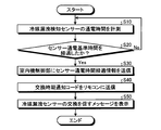
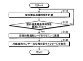
- FIG. 4 is a flowchart for explaining the notification operation of the replacement timing of the refrigerant leakage detection sensor 32 of the air conditioner 1 according to Embodiment 1 of the present invention.
- the process shown in FIG. 4 is performed not only during the air conditioning operation of the air conditioner 1 but in a state where the air conditioner 1 is energized.
- the energization time measuring unit 32b of the refrigerant leak detection sensor 32 is a sensor energization that is the time during which the refrigerant leak detection sensor 32 is energized from the indoor unit power supply circuit unit 33 of the indoor unit 3 since the initial startup. Measure time.
- the sensor energization time is measured by connecting a voltmeter to a power line that energizes the refrigerant leakage detection sensor 32 from the indoor unit power supply circuit unit 33 and measuring the time during which a predetermined supply voltage to the refrigerant leakage detection sensor 32 is detected. By doing so, measurement is possible.
- the energization time measurement unit 32b determines whether the measured sensor energization time has passed a predetermined sensor reference energization time.
- the sensor reference energization time is a sensor energization time serving as a reference for determining the necessity of replacement of the refrigerant leakage detection sensor 32 due to deterioration over time.
- the energization time measurement unit 32b determines that the refrigerant leakage detection sensor 32 needs to be replaced when the measured sensor energization time has exceeded a predetermined sensor reference energization time.
- the sensor reference energization time is stored in advance in the energization time measurement unit 32b.
- An energization time that is less than the energization time of the refrigerant leak detection sensor 32 that is estimated to cause a decrease in detection performance of the refrigerant leak detection sensor 32 is set. That is, the sensor reference energization time is provided with a time difference from the energization time of the refrigerant leak detection sensor 32, which is estimated to cause a decrease in detection performance of the refrigerant leak detection sensor 32. This time difference is set in consideration of the time when it is considered that the user can cope with the replacement of the refrigerant leakage detection sensor 32 after the user is notified of the necessity of replacement of the refrigerant leakage detection sensor 32.
- step S20 If it is determined that the sensor energization time has not passed the predetermined sensor reference energization time, that is, if No in step S20, the process returns to step S10.
- the energization time measurement unit 32b in step S30 passes the predetermined sensor reference energization time.
- the sensor energization time elapsed information to the effect is transmitted to the indoor unit control unit 35 of the indoor unit 3.
- the indoor unit control unit 35 determines that the necessity of replacement of the refrigerant leakage detection sensor 32 has been detected when the sensor energization time elapsed information is received. That is, the indoor unit control unit 35 determines that the necessity of replacement of the refrigerant leakage detection sensor 32 has been detected when the energization time measurement unit 32b detects that the predetermined sensor reference energization time has elapsed.
- the indoor unit control unit 35 sends a message as replacement time notification information instructing notification of the necessity of replacement of the refrigerant leakage detection sensor 32. Is sent to the remote control unit 45 of the remote controller 4.
- the remote control unit 45 When receiving the replacement time notification code, the remote control unit 45 refers to the information for determining the contents of the code stored in the remote control storage unit 44 in advance, and the replacement time notification code is detected by the refrigerant leak detection sensor 32. It is determined that the message is an instruction to display on the display unit 41 a message prompting replacement of the refrigerant, that is, a message notifying the necessity of replacement of the refrigerant leakage detection sensor 32.
- the remote controller control unit 45 causes the display unit 41 to display a message including a message character string corresponding to the replacement time notification code and notifying the necessity of replacement of the refrigerant leakage detection sensor 32. That is, the remote control unit 45 performs control to display a message on the display unit 41 notifying the necessity of replacement of the refrigerant leakage detection sensor 32 based on the replacement time notification code, which is maintenance information.
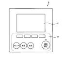
- FIG. 5 is a diagram showing an example of the external configuration of the air conditioner remote control 4 according to Embodiment 1 of the present invention.
- FIG. 6 is a diagram showing an example of a message notifying the necessity of replacement of the refrigerant leakage detection sensor 32 displayed on the display unit 41 of the remote controller 4 of the air conditioner according to Embodiment 1 of the present invention.
- FIG. 6 shows a state in which the message “Replace refrigerant leak detection sensor” is displayed on the display unit 41 of the remote controller 4 as a message notifying that the refrigerant leak detection sensor 32 needs to be replaced.
- the user can quickly leak the refrigerant.
- the necessity of replacement of the detection sensor 32 can be grasped. Thereby, the user can replace the refrigerant leak detection sensor 32 before the detection performance of the refrigerant leak detection sensor 32 is deteriorated due to the energization time of the refrigerant leak detection sensor 32.
- the message notifying the necessity of replacement of the refrigerant leak detection sensor 32 is a message prompting the user to replace the refrigerant leak detection sensor 32 and is not related to the operation of the air conditioner 1. That is, even when a message notifying that the refrigerant leakage detection sensor 32 needs to be replaced is displayed on the display unit 41 of the remote controller 4, the outdoor unit control unit 23 and the indoor unit control unit 35 stop the operation of the air conditioner. There is no control to do. Therefore, even when a message notifying that the refrigerant leakage detection sensor 32 needs to be replaced is displayed on the display unit 41 of the remote controller 4 during the operation of the air conditioner 1, the outdoor unit control unit 23 and the indoor unit control unit 35 are The operation of the air conditioner 1 can be maintained.
- the refrigerant leakage detection sensor 32 is provided in the indoor unit 3, but the arrangement of the refrigerant leakage detection sensor 32 is not limited to this.
- the refrigerant leakage detection sensor 32 may be provided in the outdoor unit 2 and is a position separated from the outdoor unit 2 or a position separated from the indoor unit 3 and a position where refrigerant leakage in the air conditioner 1 can be detected. What is necessary is just to be provided.
- a plurality of refrigerant leak detection sensors 32 may be provided.
- the air conditioner 1 when the air conditioner 1 according to the first embodiment detects that the sensor energization time has passed the predetermined sensor reference energization time, the air conditioner 1 notifies the necessity of replacement of the refrigerant leakage detection sensor 32. Control to display the message on the display unit 41 of the remote controller 4 is performed. As a result, the air conditioner 1 determines that the user needs to replace the refrigerant leak detection sensor 32, that is, the time for the user to replace the refrigerant leak detection sensor 32 is due to the deterioration of the refrigerant leak detection sensor 32 over time. It is possible to notify the user before the deterioration of the detection performance of the refrigerant leakage detection sensor 32 due to the occurrence.
- the user can quickly replace the refrigerant leak detection sensor 32 before the detection performance of the refrigerant leak detection sensor 32 is deteriorated. Thereby, it becomes possible to always maintain the detection performance of the refrigerant leakage detection sensor 32 in a normal state, the detection performance of the refrigerant leakage in the refrigerant leakage detection sensor 32 can be maintained in a normal state, and the refrigerant leakage in the air conditioner 1 The reliability of detection is improved.
- Embodiment 2 FIG. In the first embodiment described above, the case where the energization time measurement unit 32b of the refrigerant leak detection sensor 32 measures the sensor energization time and determines that the refrigerant leak detection sensor 32 needs to be replaced has been described. When it is determined that the refrigerant leak detection sensor 32 has detected the necessity for replacement of the refrigerant leak detection sensor 32 and notifies the indoor unit control unit 35 to that effect, the indoor unit control unit 35 determines whether the refrigerant leak detection sensor 32 We do not know energization time.
- the indoor unit control unit 35 stores the lifetime of the refrigerant leak detection sensor 32 in advance. Further, the indoor unit control unit 35 measures the elapsed time from the initial activation of the air conditioner 1, that is, the indoor unit energization time that is the energization time of the indoor unit 3.
- the indoor unit energization time is the same as the sensor energization time.
- the indoor unit control unit 35 calculates a grace time that is a difference time between the sensor energization time and the lifetime of the refrigerant leakage detection sensor 32.
- the lifetime is the time when the detection performance of the refrigerant leakage detection sensor 32 is lowered due to the energization time of the refrigerant leakage detection sensor 32, that is, the detection performance of the refrigerant leakage detection sensor 32 is lowered due to deterioration over time. It is.
- the grace time is the remaining time from when it is determined that the sensor energization time has passed the predetermined sensor reference energization time until the time when it is estimated that the detection performance of the refrigerant leakage detection sensor 32 is deteriorated.
- the indoor unit control unit 35 transmits the calculated grace time to the remote control unit 45 of the remote controller 4 together with the replacement time notification code in step S40 described in the first embodiment.
- the remote control control unit 45 causes the display unit 41 to display the grace time together with a message notifying the necessity of replacement of the refrigerant leakage detection sensor 32.
- the refrigerant leak detection sensor 32 when the refrigerant leak detection sensor 32 is replaced, it is necessary to newly start measuring the indoor unit energization time in the indoor unit control unit 35. In this case, by performing a reset operation for resetting the measured value of the indoor unit energization time in the indoor unit control unit 35 from the remote controller 4, the measurement of the indoor unit energization time in the indoor unit control unit 35 can be newly started.
- the air conditioner in the second embodiment can provide a grace period to the user in addition to the effects in the first embodiment.
- the user can systematically advance replacement of the refrigerant leakage detection sensor 32 with reference to the grace time.
- Embodiment 3 the indoor unit control unit 35 of the indoor unit 3 measures the elapsed time from the initial start-up of the air conditioner 1, that is, the indoor unit energization time that is the energization time of the indoor unit 3, and detects refrigerant leakage. A case where the necessity of replacing the sensor 32 is determined will be described.
- the air conditioner according to the third embodiment is basically the same as the embodiment except that the indoor unit energization time, which is the energization time of the indoor unit 3, is measured to determine the necessity of replacement of the refrigerant leakage detection sensor 32. 1 has the same configuration and function as the air conditioner 1 in FIG.
- Embodiment 3 items that are not particularly described are the same as those in Embodiment 1, and the same functions and configurations are described using the same reference numerals. Further, the description of the same function and configuration of the air conditioner of the third embodiment as that of the air conditioner 1 of the first embodiment will be omitted.
- FIG. 7 is a flowchart for explaining the notification operation of the replacement timing of the refrigerant leak detection sensor 32 of the air conditioner according to Embodiment 3 of the present invention. The process shown in FIG. 7 is performed while the air conditioner is energized.
- the indoor unit control unit 35 of the indoor unit 3 is an elapsed time from the initial activation of the air conditioner 1, that is, an energization time of the indoor unit 3 from the initial activation of the air conditioner 1. Measure machine energization time.
- the indoor unit control unit 35 determines whether or not the measured indoor unit energization time has passed a predetermined indoor unit reference energization time.
- the predetermined indoor unit reference energization time is the energization time of the indoor unit 3 that serves as a reference for determining the necessity of replacement of the refrigerant leakage detection sensor 32 due to deterioration over time.
- the indoor unit control unit 35 determines that the refrigerant leakage detection sensor 32 needs to be replaced when the measured indoor unit energization time has passed the predetermined indoor unit reference energization time.
- the indoor unit reference energization time is stored in advance in the indoor unit control unit 35.
- the indoor unit reference energization time is used to notify the user of the necessity to replace the refrigerant leak detection sensor 32 before the detection performance of the refrigerant leak detection sensor 32 is deteriorated due to deterioration over time.
- step S120 If it is determined that the indoor unit energization time has not passed the predetermined indoor unit reference energization time, that is, if No in step S120, the process returns to step S110.
- the indoor unit control unit 35 When it is determined that the indoor unit energization time has passed the predetermined indoor unit reference energization time, that is, in the case of Yes in step S120, the indoor unit control unit 35 detects the necessity of replacement of the refrigerant leakage detection sensor 32. Is determined. If the indoor unit control unit 35 determines that the necessity for replacement of the refrigerant leakage detection sensor 32 has been detected, the indoor unit control unit 35 transmits a replacement time notification code to the remote control unit 45 of the remote controller 4 in step S130.
- the remote control unit 45 When receiving the replacement time notification code, the remote control unit 45 refers to the information for determining the contents of the code stored in the remote control storage unit 44 in advance, and the replacement time notification code is detected by the refrigerant leak detection sensor 32. It is determined that the instruction is to display a message notifying the necessity of replacement on the display unit 41. Then, in step S140, the remote control unit 45 causes the display unit 41 to display a message consisting of a message character string that corresponds to the replacement time notification code and notifying the necessity of replacement of the refrigerant leakage detection sensor 32. That is, the remote control unit 45 performs control to display on the display unit 41 a message notifying the necessity of replacement of the refrigerant leakage detection sensor 32 based on the replacement time notification code.
- the refrigerant leakage is also detected by the indoor unit control unit 35 of the indoor unit 3 measuring the indoor unit energization time that is the energization time of the indoor unit 3 and determining the necessity of replacement of the refrigerant leak detection sensor 32.
- the need for replacement of the detection sensor 32 that is, the replacement timing of the refrigerant leakage detection sensor 32, indicates that the detection performance of the refrigerant leakage detection sensor 32 is deteriorated due to deterioration over time of the refrigerant leakage detection sensor 32. The user can be notified before.
- the indoor unit control unit 35 of the indoor unit 3 can also determine whether the refrigerant leakage detection sensor 32 needs to be replaced properly due to a defect in the refrigerant leakage detection sensor 32. By determining whether or not the refrigerant leakage detection sensor 32 needs to be replaced, it is determined that the replacement timing of the refrigerant leakage detection sensor 32 has come.
- the refrigerant leakage detection sensor 32 caused by the deterioration of the refrigerant leakage detection sensor 32 over time.
- the user can be notified before the degradation of the detection performance occurs. That is, by using the two determination processes in combination, the refrigerant leak detection sensor 32 is not notified to the user that it is time to replace the refrigerant leak detection sensor 32 due to a defect in the refrigerant leak detection sensor 32.
- the reliability of refrigerant leakage detection in the air conditioner 1 that can prevent the lifetime from being exceeded is further improved.
- a high-accuracy transmitter or a dedicated integrated circuit may be mounted on the circuit constituting the indoor unit control unit 35. Further, the indoor unit control unit 35 may periodically receive time data from the remote controller 4 and correct the measured value of the indoor unit energization time in the indoor unit control unit 35.
- the operation time of the indoor unit 3 or the time during which the compressor provided in the outdoor unit 2 is operating may be measured and used. It is also possible to detect refrigerant leakage by determining that the refrigerant leakage detection sensor 32 needs to be replaced using the indoor unit energization time, the operation time of the indoor unit 3, or the time during which the compressor included in the outdoor unit 2 is operating. It is possible to notify the user that it is time to replace the sensor 32 before the detection performance of the refrigerant leak detection sensor 32 is deteriorated due to deterioration of the refrigerant leak detection sensor 32 over time.
- the state value measured in the indoor unit 3 or the outdoor unit 2 is used in place of the energization time of the refrigerant leakage detection sensor 32.
- the energization time measurement unit 32b is not necessary, and the configuration of the refrigerant leakage detection sensor 32 can be simplified.
- the indoor unit control unit 35 of the indoor unit 3 may be replaced depending on the situation. For this reason, the measured value of the indoor unit energization time is transmitted to the outdoor unit 2, and the information on the measured value of the indoor unit energization time is shared, so that the backup can be performed when the indoor unit 3 or the outdoor unit 2 is replaced. can do.
- the air conditioner according to Embodiment 3 performs the determination that the refrigerant leakage detection sensor 32 needs to be replaced by the indoor unit control unit 35, thereby replacing the refrigerant leakage detection sensor 32. Can be notified to the user before the deterioration of the detection performance of the refrigerant leak detection sensor 32 due to the deterioration of the refrigerant leak detection sensor 32 over time, and the reliability of the detection of the refrigerant leak can be improved.
- a high air conditioner can be provided.
- Embodiment 4 FIG.
- the remote controller control unit 45 displays on the display unit 41 a message that includes a message character string and notifies the necessity of replacement of the refrigerant leakage detection sensor 32 corresponding to the replacement time notification code.
- the remote control control unit 45 may cause the display unit 41 to display a message code corresponding to the replacement time notification code instead of the message character string.
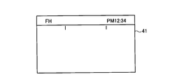
- FIG. 8 is a diagram illustrating an example of a message notifying the necessity of replacement of the refrigerant leakage detection sensor 32 displayed on the display unit 41 of the remote controller 4 of the air conditioner according to Embodiment 4 of the present invention.
- FIG. 8 shows a state in which the message code “FH” is displayed on the display unit 41 of the remote controller 4 as a message notifying the necessity of replacement of the refrigerant leakage detection sensor 32.
- the user can also quickly display the refrigerant by displaying a message notifying the necessity of replacement of the refrigerant leakage detection sensor 32 as a message code on the display unit 41 of the remote controller 4 that is the user's operating device.
- the necessity of replacement of the leak detection sensor 32 can be grasped. Thereby, the user can respond
- the message character string shown in FIG. 6 and the message code shown in FIG. 8 may be alternately displayed on the display unit 41 of the remote controller 4 at predetermined intervals. Also in this case, the above-described grace time may be displayed together.
- the air conditioner also displays the message code corresponding to the replacement time notification code on the display unit 41 of the remote controller 4, so that the user needs to replace the refrigerant leakage detection sensor 32, that is, the user It is possible to notify the user that it is time to replace the leak detection sensor 32 before the detection performance of the refrigerant leak detection sensor 32 deteriorates.
- the configuration described in the above embodiment shows an example of the contents of the present invention, and can be combined with another known technique, and can be combined with other configurations without departing from the gist of the present invention. It is also possible to omit or change the part.
Landscapes
- Engineering & Computer Science (AREA)
- Chemical & Material Sciences (AREA)
- Combustion & Propulsion (AREA)
- Mechanical Engineering (AREA)
- General Engineering & Computer Science (AREA)
- Human Computer Interaction (AREA)
- Physics & Mathematics (AREA)
- General Physics & Mathematics (AREA)
- Automation & Control Theory (AREA)
- Air Conditioning Control Device (AREA)
Abstract
室内機(3)は、室内機(3)の動作を制御する室内機制御部(35)を備え、リモートコントローラー(4)は、リモートコントローラー(4)の動作を制御するリモートコントローラー制御部(45)と、リモートコントローラー(4)内の各種情報を表示する表示部(41)と、を備える。室内機制御部(35)は、冷媒漏洩検知センサー(32)の交換の必要性を検知したと判定した場合に、冷媒漏洩検知センサー(32)の交換の必要性の通知を指示する交換時期通知情報をリモートコントローラー(4)に送信する制御を行う。リモートコントローラー制御部(45)は、交換時期通知情報に基づいて、冷媒漏洩検知センサー(32)の交換の必要性を通知するメッセージを表示部(41)に表示する制御を行う。
Description
本発明は、冷媒を使用して空気調和を行う空気調和機に関する。
従来、空気調和機の異常に対応する技術として、特許文献1には、異常発生時に室内機からリモートコントローラーに対して、異常内容と、発生した異常に対する対処方法に関するデータとを送信する空気調和機が開示されている。以下、リモートコントローラーを、リモコンと呼ぶ場合がある。
空気調和機の異常の1つに、冷媒の漏洩がある。冷媒の漏洩が発生した場合には、空気調和機における運転効率の低下が生じ、最終的には運転不可能な状態となる。冷媒の漏洩に対する対策として、冷媒漏洩検知センサーを用いて冷媒の漏洩を検知することがある。
しかしながら、冷媒の漏洩を検知するセンサーの中には、寿命により冷媒の漏洩の検知性能の低下が発生するものがある。冷媒の漏洩の検知性能の低下が発生した場合には、冷媒の漏洩を正確に検知できなくなる場合があり、空気調和機の冷媒漏洩の検知の信頼性が低下する。
本発明は、上記に鑑みてなされたものであって、冷媒漏洩検知センサーにおける冷媒漏洩の検知性能を正常な状態に維持でき、冷媒漏洩の検知の信頼性の高い空気調和機を得ることを目的とする。
上述した課題を解決し、目的を達成するために、本発明にかかる空気調和機は、室内に配置された室内機と、屋外に配置されて室内機との間で冷媒が循環される室外機と、室内機と通信可能に接続されたリモートコントローラーと、冷媒の漏洩を検知する冷媒漏洩検知センサーと、を備える。室内機は、室内機の動作を制御する室内機制御部を備え、リモートコントローラーは、リモートコントローラーの動作を制御するリモートコントローラー制御部と、リモートコントローラー内の各種情報を表示する表示部と、を備える。室内機制御部は、冷媒漏洩検知センサーの交換の必要性を検知したと判定した場合に、冷媒漏洩検知センサーの交換の必要性の通知を指示する交換時期通知情報をリモートコントローラーに送信する制御を行う。リモートコントローラー制御部は、交換時期通知情報に基づいて、冷媒漏洩検知センサーの交換の必要性を通知するメッセージを表示部に表示する制御を行う。
本発明にかかる空気調和機は、冷媒漏洩検知センサーにおける冷媒漏洩の検知性能を正常な状態に維持でき、冷媒漏洩の検知の信頼性の高い空気調和機が得られる、という効果を奏する。
以下に、本発明の実施の形態における空気調和機を図面に基づいて詳細に説明する。なお、この実施の形態によりこの発明が限定されるものではない。
実施の形態1.
図1は、本発明の実施の形態1における空気調和機1の構成を示す模式図である。図2は、本発明の実施の形態1における空気調和機1の要部機能ブロック図である。本実施の形態1における空気調和機1は、屋外に配置された室外機2、室内に配置された室内機3および空気調和機1の動作を遠隔操作するリモートコントローラー4を備える。
図1は、本発明の実施の形態1における空気調和機1の構成を示す模式図である。図2は、本発明の実施の形態1における空気調和機1の要部機能ブロック図である。本実施の形態1における空気調和機1は、屋外に配置された室外機2、室内に配置された室内機3および空気調和機1の動作を遠隔操作するリモートコントローラー4を備える。
室外機2と室内機3とは、冷媒配管5および内外通信線6で接続されており、冷媒配管5には熱交換を行うための冷媒が流れている。空気調和機1は、一つの完結した冷凍サイクルを室外機2と室内機3とで形成している。空気調和機1は、冷媒配管5を通って室外機2と室内機3との間を循環する冷媒を使用して、空調対象空間である室内の空気と室外の空気との間で熱移動を行い、室内に対する空気調和を実現している。図1および図2では空気調和機1の要部の構成のみを示しており、送風ファン、圧縮機を含む冷凍サイクル機構といった各種構成部の図示は省略している。
室外機2は、主たる構成として、室外機2内の各構成部を動作させるための制御電源を生成する室外機電源回路部21と、空気調和機1により空調を行う際に必要な各種の情報を記憶する室外機記憶部22と、空気調和機1により空調を行うために室外機2内の各構成部を制御して室外機2の動作を制御する室外機制御部23と、室内機3の室内機通信部36との間で情報の通信を行う室外機通信部24と、を備える。室外機2の構成部は、互いに情報の授受が可能である。
室外機制御部23は、例えば、図3に示したハードウェア構成の処理回路として実現される。図3は、本発明の実施の形態1における処理回路のハードウェア構成の一例を示す図である。室外機制御部23を構成する各構成要素が図3に示す処理回路により実現される場合、室外機制御部23を構成する各構成要素は、プロセッサ101がメモリ102に記憶されたプログラムを実行することにより、実現される。また、複数のプロセッサおよび複数のメモリが連携して上記機能を実現してもよい。また、室外機制御部23の機能のうちの一部を電子回路として実装し、他の部分をプロセッサ101およびメモリ102を用いて実現するようにしてもよい。また、室外機通信部24を、同様にプロセッサ101がメモリ102に記憶されたプログラムを実行することにより、実現されるように構成してもよい。また、室外機通信部24を実現するためのプロセッサおよびメモリは、室外機制御部23を実現するプロセッサおよびメモリと同一であってもよいし、別のプロセッサおよびメモリであってもよい。
室内機3は、主たる構成として、室内機3が配置された室内の温度、配管の温度といった空気調和機1における空調処理に必要な各種の温度を検知する室内温度検知部である温度センサー31と、冷媒の漏洩を検知する冷媒漏洩検知センサー32と、室内機3内の各構成部を動作させるための制御電源を生成する室内機電源回路部33と、空気調和機1における空調処理に必要な各種の情報を記憶する室内機記憶部34と、空気調和機1により空調を行うために室内機3内の各構成部を制御して室内機3の動作を制御する室内機制御部35と、リモコン4との間で情報の通信を行う室内機通信部36と、を備える。
冷媒漏洩検知センサー32は、冷媒の漏洩を検知するセンサー部32aと、室内機3の室内機電源回路部33から冷媒漏洩検知センサー32に通電されている時間を計測する通電時間計測部32bと、を備える。
冷媒漏洩検知センサー32は、半導体式ガスセンサーが用いられる。なお、冷媒漏洩検知センサー32は、半導体式ガスセンサーに限定されず、赤外線式ガスセンサーといった他の検知方式のガスセンサーであってもよい。
冷媒漏洩検知センサー32は通電時間に応じて、冷媒漏洩の検知における検知性能の劣化が発生する。このため、通電時間計測部32bは、冷媒漏洩の検知における検知精度の劣化が発生する前にユーザに交換時期を知らせるために、冷媒漏洩検知センサー32の通電時間を計測し、ある一定の通電時間を経過した場合に交換時期を知らせるために、室内機制御部35にその旨を通知する。なお、ここでの交換には、修理の意味が含まれる。
室内機電源回路部33は、図示しない外部電源である商用交流電源と電源線により接続されている。室内機電源回路部33は、商用交流電源から供給される交流電源から、室内機3内の各構成部を動作させるための制御電源を生成する。室内機電源回路部33は、温度センサー31、冷媒漏洩検知センサー32、室内機記憶部34、室内機制御部35および室内機通信部36に、生成した制御電源を給電可能に接続されている。
室内機記憶部34は、空気調和機1により空調を行う際に必要な各種の情報を記憶する。
室内機制御部35は、空気調和機1により空調を行うために室内機3内の各構成部を制御する。また、室内機制御部35は、空気調和機1における冷媒漏洩検知センサー32の交換時期の通知動作を制御する。
室内機通信部36は、内外通信線6を介して室外機2の室外機通信部24との間で互いに情報の双方向通信が可能である。
室内機制御部35は、例えば、図3に示したハードウェア構成の処理回路として実現される。室内機制御部35を構成する各構成要素が図3に示す処理回路により実現される場合、室内機制御部35を構成する各構成要素は、プロセッサ101がメモリ102に記憶されたプログラムを実行することにより、実現される。また、複数のプロセッサおよび複数のメモリが連携して上記機能を実現してもよい。また、室内機制御部35の機能のうちの一部を電子回路として実装し、他の部分をプロセッサ101およびメモリ102を用いて実現するようにしてもよい。また、室内機通信部36を、同様にプロセッサ101がメモリ102に記憶されたプログラムを実行することにより、実現されるように構成してもよい。また、室内機通信部36を実現するためのプロセッサおよびメモリは、室内機制御部35を実現するプロセッサおよびメモリと同一であってもよいし、別のプロセッサおよびメモリであってもよい。
リモコン4は、現在の時刻を設定する時計機能、空気調和機1による空調における室内温度の目標となる設定温度といった、空気調和機1による空調において必要となる情報を設定する操作装置である。リモコン4は、主たる構成として、各種情報を表示する表示部41と、設定操作を受け付ける操作部42と日時に関する時計機能を有するカレンダー機能部43と、空気調和機1における空調処理に必要な各種の情報を記憶するリモートコントローラー記憶部44と、リモコン4の動作および冷媒漏洩検知センサー32の交換時期の通知動作を制御するリモートコントローラー制御部45と、室内機3の室内機通信部36との間で情報の通信を行うリモートコントローラー通信部46と、を備える。リモコン通信部46は、室内機3の室内機通信部36との間で有線または無線より互いに情報の双方向通信が可能である。
リモコン制御部45は、例えば、図3に示したハードウェア構成の処理回路として実現される。リモコン制御部45を構成する各構成要素が図3に示す処理回路により実現される場合、リモコン制御部45を構成する各構成要素は、プロセッサ101がメモリ102に記憶されたプログラムを実行することにより、実現される。また、複数のプロセッサおよび複数のメモリが連携して上記機能を実現してもよい。また、リモコン制御部45の機能のうちの一部を電子回路として実装し、他の部分をプロセッサ101およびメモリ102を用いて実現するようにしてもよい。また、リモコン通信部46を、同様にプロセッサ101がメモリ102に記憶されたプログラムを実行することにより、実現されるように構成してもよい。また、リモコン通信部46を実現するためのプロセッサおよびメモリは、リモコン制御部45を実現するプロセッサおよびメモリと同一であってもよいし、別のプロセッサおよびメモリであってもよい。
つぎに、本実施の形態1における空気調和機1の動作について説明する。図4は、本発明の実施の形態1における空気調和機1の冷媒漏洩検知センサー32の交換時期の通知動作を説明するフローチャートである。図4に示す処理は、空気調和機1の空調運転動作時に限らず、空気調和機1に通電されている状態において行われる。
まず、ステップS10において、冷媒漏洩検知センサー32の通電時間計測部32bは、初期の起動時から室内機3の室内機電源回路部33より冷媒漏洩検知センサー32に通電されている時間であるセンサー通電時間を計測する。センサー通電時間の計測は、室内機電源回路部33から冷媒漏洩検知センサー32に通電する電源線に電圧計を接続し、冷媒漏洩検知センサー32への既定の供給電圧が検知されている時間を計測することにより、計測可能である。
つぎに、ステップS20において、通電時間計測部32bは、計測したセンサー通電時間が既定のセンサー基準通電時間を経過したか否かを判定する。センサー基準通電時間は、経時的劣化に起因した冷媒漏洩検知センサー32の交換の必要性を判定するための基準となる、センサー通電時間である。通電時間計測部32bは、計測したセンサー通電時間が既定のセンサー基準通電時間を経過した場合に、冷媒漏洩検知センサー32の交換の必要性があると判定する。センサー基準通電時間は、あらかじめ通電時間計測部32bに記憶されている。
センサー基準通電時間は、冷媒漏洩検知センサー32の通電時間に起因した冷媒漏洩検知センサー32の検知性能の低下が発生する前に冷媒漏洩検知センサー32の交換の必要性をユーザに通知するために、冷媒漏洩検知センサー32の検知性能の低下が発生すると推定される冷媒漏洩検知センサー32の通電時間よりも少ない通電時間が設定されている。すなわち、センサー基準通電時間には、冷媒漏洩検知センサー32の検知性能の低下が発生すると推定される冷媒漏洩検知センサー32の通電時間との時間差が設けられている。この時間差は、冷媒漏洩検知センサー32の交換の必要性がユーザに通知されてからユーザが冷媒漏洩検知センサー32の交換に対応可能と考えられる時間を考慮して設定される。
センサー通電時間が既定のセンサー基準通電時間を経過していないと判定された場合、すなわちステップS20においてNoの場合は、ステップS10に戻る。
センサー通電時間が既定のセンサー基準通電時間を経過したと判定された場合、すなわちステップS20においてYesの場合は、ステップS30において通電時間計測部32bは、センサー通電時間が既定のセンサー基準通電時間を経過した旨のセンサー通電時間経過情報を室内機3の室内機制御部35に送信する。
室内機制御部35は、センサー通電時間経過情報を受信すると冷媒漏洩検知センサー32の交換の必要性を検知したと判定する。すなわち、室内機制御部35は、通電時間計測部32bにおいて既定のセンサー基準通電時間を経過したことを検知した場合に、冷媒漏洩検知センサー32の交換の必要性を検知したと判定する。室内機制御部35は、冷媒漏洩検知センサー32の交換の必要性を検知したと判定すると、ステップS40において、冷媒漏洩検知センサー32の交換の必要性の通知を指示する交換時期通知情報として、メッセージに対応した交換時期通知コードをリモコン4のリモコン制御部45に送信する。
リモコン制御部45は、交換時期通知コードを受信すると、あらかじめリモコン記憶部44に記憶している、コードの内容を判別するための情報を参照して、交換時期通知コードが、冷媒漏洩検知センサー32の交換を促すメッセージ、すなわち冷媒漏洩検知センサー32の交換の必要性を通知するメッセージを表示部41に表示させる指示であると判定する。そして、リモコン制御部45は、ステップS50において、交換時期通知コードに対応したメッセージ文字列からなり冷媒漏洩検知センサー32の交換の必要性を通知するメッセージを表示部41に表示させる。すなわち、リモコン制御部45は、メンテナンス情報であり交換時期通知コードに基づいて冷媒漏洩検知センサー32の交換の必要性を通知するメッセージを表示部41に表示する制御を行う。
図5は、本発明の実施の形態1における空気調和機のリモコン4の外観構成の一例を示す図である。図6は、本発明の実施の形態1における空気調和機のリモコン4の表示部41に表示された、冷媒漏洩検知センサー32の交換の必要性を通知するメッセージの一例を示す図である。図6においては、冷媒漏洩検知センサー32の交換の必要性を通知するメッセージとして、「冷媒漏洩検知センサー交換」のメッセージがリモコン4の表示部41に表示された状態を示している。
図6に示すように、冷媒漏洩検知センサー32の交換の必要性を通知するメッセージを、ユーザの操作装置であるリモコン4の表示部41においてメッセージ文として表示することにより、ユーザは、すばやく冷媒漏洩検知センサー32の交換の必要性を把握することできる。これにより、ユーザは、冷媒漏洩検知センサー32の通電時間に起因した冷媒漏洩検知センサー32の検知性能の低下が発生する前に、冷媒漏洩検知センサー32の交換を行うことができる。
これにより、冷媒漏洩検知センサー32の通電時間に起因した冷媒漏洩検知センサー32の検知性能の低下が発生する前に、ユーザに冷媒漏洩検知センサー32の交換の必要性を通知すること、すなわちユーザに冷媒漏洩検知センサー32の交換時期が来ていることを通知することができる。
また、冷媒漏洩検知センサー32の交換の必要性を通知するメッセージは、ユーザに対して冷媒漏洩検知センサー32の交換を促すメッセージであり、空気調和機1の運転には関係しない。すなわち、冷媒漏洩検知センサー32の交換の必要性を通知するメッセージがリモコン4の表示部41に表示された場合でも、室外機制御部23および室内機制御部35は、空気調和機の運転を停止する制御を行うことはない。したがって、空気調和機1の運転中に冷媒漏洩検知センサー32の交換の必要性を通知するメッセージがリモコン4の表示部41に表示された場合でも、室外機制御部23および室内機制御部35は、空気調和機1の運転を維持することができる。
なお、上記においては、冷媒漏洩検知センサー32が室内機3に設けられた場合について示したが、冷媒漏洩検知センサー32の配置はこれに限定されない。冷媒漏洩検知センサー32は、室外機2に設けられてもよく、また室外機2から離間した位置もしくは室内機3から離間した位置であって空気調和機1における冷媒の漏洩を検知可能な位置に設けられればよい。また、冷媒漏洩検知センサー32は、複数設けられてもよい。
冷媒漏洩検知センサー32が室外機2または室内機3から離れて設けられる場合には、室外機2の室外機通信部24との間または室内機3の室内機通信部36との間で有線または無線より情報の通信が可能な室内機通信部を冷媒漏洩検知センサー32に設ければよい。
上述したように、本実施の形態1における空気調和機1は、センサー通電時間が既定のセンサー基準通電時間を経過したことを検知した場合に、冷媒漏洩検知センサー32の交換の必要性を通知するメッセージをリモコン4の表示部41に表示する制御を行う。これにより、空気調和機1は、ユーザに冷媒漏洩検知センサー32の交換の必要性、すなわちユーザに冷媒漏洩検知センサー32の交換時期が来ていることを、冷媒漏洩検知センサー32の経時的劣化に起因した冷媒漏洩検知センサー32の検知性能の低下が発生する前にユーザに通知することができる。
そして、ユーザは、冷媒漏洩検知センサー32の検知性能の低下が発生する前に、迅速に冷媒漏洩検知センサー32の交換することが可能となる。これにより、冷媒漏洩検知センサー32の検知性能を常に正常な状態に維持することが可能となり、冷媒漏洩検知センサー32における冷媒漏洩の検知性能を正常な状態に維持でき、空気調和機1における冷媒漏洩の検知の信頼性が向上する。
実施の形態2.
上述した実施の形態1では、冷媒漏洩検知センサー32の通電時間計測部32bがセンサー通電時間を計測して冷媒漏洩検知センサー32の交換の必要性があると判定する場合について説明した。冷媒漏洩検知センサー32が冷媒漏洩検知センサー32の交換の必要性を検知したと判定し、その旨を室内機制御部35に通知する場合には、室内機制御部35は冷媒漏洩検知センサー32の通電時間を把握していない。
上述した実施の形態1では、冷媒漏洩検知センサー32の通電時間計測部32bがセンサー通電時間を計測して冷媒漏洩検知センサー32の交換の必要性があると判定する場合について説明した。冷媒漏洩検知センサー32が冷媒漏洩検知センサー32の交換の必要性を検知したと判定し、その旨を室内機制御部35に通知する場合には、室内機制御部35は冷媒漏洩検知センサー32の通電時間を把握していない。
そこで、本実施の形態2では、室内機制御部35が、あらかじめ冷媒漏洩検知センサー32の寿命時間を記憶している。また、室内機制御部35が、空気調和機1の初期の起動からの経過時間、すなわち室内機3の通電時間である室内機通電時間を計測する。ここで、空気調和機1が起動しているときに、室内機3および冷媒漏洩検知センサー32の両方に通電されている場合には、室内機通電時間は、センサー通電時間と同じ時間である。
そして、室内機制御部35が、センサー通電時間と冷媒漏洩検知センサー32の寿命時間との差分時間である猶予時間を算出する。ここで寿命時間とは、冷媒漏洩検知センサー32の通電時間に起因した冷媒漏洩検知センサー32の検知性能の低下、すなわち経時的劣化に起因した冷媒漏洩検知センサー32の検知性能の低下が発生する時間である。猶予時間は、センサー通電時間が既定のセンサー基準通電時間を経過したと判定された時から、冷媒漏洩検知センサー32の検知性能の低下が発生すると推定される時間までの残り時間である。
この場合、室内機制御部35は、実施の形態1において説明したステップS40において、算出した猶予時間を交換時期通知コードとともにリモコン4のリモコン制御部45に送信する。リモコン制御部45は、この猶予時間の時間を、冷媒漏洩検知センサー32の交換の必要性を通知するメッセージとともに表示部41に表示させる。これにより、ユーザは、猶予時間を把握できるため、冷媒漏洩検知センサー32の交換の手配を、猶予時間を参考にして計画的に進めることが可能となる。
なお、冷媒漏洩検知センサー32を交換した場合、室内機制御部35における室内機通電時間の計測も新たに開始させることが必要である。この場合、室内機制御部35における室内機通電時間の計測値をリセットするリセット操作をリモコン4から行うことで、室内機制御部35における室内機通電時間の計測も新たに開始させることができる。
上述したように、実施の形態2における空気調和機は、実施の形態1における効果に加え、猶予時間をユーザに提供することができる。これにより、ユーザは、冷媒漏洩検知センサー32の交換の手配を、猶予時間を参考にして計画的に進めることが可能となる。
実施の形態3.
本実施の形態3では、室内機3の室内機制御部35が空気調和機1の初期の起動からの経過時間、すなわち室内機3の通電時間である室内機通電時間を計測して冷媒漏洩検知センサー32の交換の必要性を判定する場合について説明する。本実施の形態3における空気調和機は、室内機3の通電時間である室内機通電時間を計測して冷媒漏洩検知センサー32の交換の必要性を判定すること以外は、基本的に実施の形態1における空気調和機1と同じ構成および機能を有する。
本実施の形態3では、室内機3の室内機制御部35が空気調和機1の初期の起動からの経過時間、すなわち室内機3の通電時間である室内機通電時間を計測して冷媒漏洩検知センサー32の交換の必要性を判定する場合について説明する。本実施の形態3における空気調和機は、室内機3の通電時間である室内機通電時間を計測して冷媒漏洩検知センサー32の交換の必要性を判定すること以外は、基本的に実施の形態1における空気調和機1と同じ構成および機能を有する。
本実施の形態3において、特に記述しない項目については実施の形態1の場合と同様とし、同一の機能および構成については同一の符号を用いて述べることとする。また、本実施の形態3における空気調和機の、実施の形態1における空気調和機1と同一の機能および構成についての説明は省略する。
本実施の形態3における空気調和機の動作について説明する。図7は、本発明の実施の形態3における空気調和機の冷媒漏洩検知センサー32の交換時期の通知動作を説明するフローチャートである。図7に示す処理は、空気調和機の通電中において行われる。
まず、ステップS110において、室内機3の室内機制御部35は、空気調和機1の初期の起動からの経過時間、すなわち空気調和機1の初期の起動からの室内機3の通電時間である室内機通電時間を計測する。
つぎに、ステップS120において、室内機制御部35は、計測した室内機通電時間が既定の室内機基準通電時間を経過したか否かを判定する。既定の室内機基準通電時間は、経時的劣化に起因した冷媒漏洩検知センサー32の交換の必要性を判定するための基準となる室内機3の通電時間である。室内機制御部35は、計測した室内機通電時間が既定の室内機基準通電時間を経過した場合に、冷媒漏洩検知センサー32の交換の必要性があると判定する。室内機基準通電時間は、あらかじめ室内機制御部35に記憶されている。
室内機基準通電時間は、経時的劣化に起因した冷媒漏洩検知センサー32の検知性能の低下が発生する前に冷媒漏洩検知センサー32の交換の必要性をユーザに通知するために、冷媒漏洩検知センサー32の検知性能の低下が発生すると推定される冷媒漏洩検知センサー32の通電時間よりも少ない通電時間が設定されている。すなわち、室内機基準通電時間には、冷媒漏洩検知センサー32の検知性能の低下が発生すると推定される室内機通電時間との時間差が設けられている。この時間差は、冷媒漏洩検知センサー32の交換の必要性がユーザに通知されてからユーザが冷媒漏洩検知センサー32の交換に対応可能と考えられる時間を考慮して設定される。
室内機通電時間が既定の室内機基準通電時間を経過していないと判定された場合、すなわちステップS120においてNoの場合は、ステップS110に戻る。
室内機通電時間が既定の室内機基準通電時間を経過したと判定された場合、すなわちステップS120においてYesの場合は、室内機制御部35は、冷媒漏洩検知センサー32の交換の必要性を検知したと判定する。室内機制御部35は、冷媒漏洩検知センサー32の交換の必要性を検知したと判定すると、ステップS130において、交換時期通知コードをリモコン4のリモコン制御部45に送信する。
リモコン制御部45は、交換時期通知コードを受信すると、あらかじめリモコン記憶部44に記憶している、コードの内容を判別するための情報を参照して、交換時期通知コードが、冷媒漏洩検知センサー32の交換の必要性を通知するメッセージを表示部41に表示させる指示であると判定する。そして、リモコン制御部45は、ステップS140において、交換時期通知コードに対応した、メッセージ文字列からなり冷媒漏洩検知センサー32の交換の必要性を通知するメッセージを表示部41に表示させる。すなわち、リモコン制御部45は、交換時期通知コードに基づいて冷媒漏洩検知センサー32の交換の必要性を通知するメッセージを表示部41に表示する制御を行う。
上記のように、室内機3の室内機制御部35が室内機3の通電時間である室内機通電時間を計測して冷媒漏洩検知センサー32の交換の必要性を判定することによっても、冷媒漏洩検知センサー32の交換の必要性、すなわち冷媒漏洩検知センサー32の交換時期が来ていることを、冷媒漏洩検知センサー32の経時的劣化に起因した冷媒漏洩検知センサー32の検知性能の低下が発生する前にユーザに通知することができる。そして、冷媒漏洩検知センサー32の通電時間計測部32bによる冷媒漏洩検知センサー32の交換の必要性の判定と、室内機3の室内機制御部35による冷媒漏洩検知センサー32の交換の必要性の判定とを併用することが好ましい。2つの判定処理を併用することにより、冷媒漏洩検知センサー32の不良により冷媒漏洩検知センサー32の交換の必要性の判定が適切に行われない場合においても、室内機3の室内機制御部35による冷媒漏洩検知センサー32の交換の必要性の判定が行われることにより、冷媒漏洩検知センサー32の交換時期が来ていることを、冷媒漏洩検知センサー32の経時的劣化に起因した冷媒漏洩検知センサー32の検知性能の低下が発生する前にユーザに通知することができる。すなわち、2つの判定処理を併用することにより、冷媒漏洩検知センサー32の不良に起因して、ユーザに冷媒漏洩検知センサー32の交換時期が来ていることを通知せずに冷媒漏洩検知センサー32の寿命時間が超過することを防止できる、空気調和機1における冷媒漏洩の検知の信頼性がより向上する。
また、室内機通電時間の計測精度を向上させるために、室内機制御部35を構成する回路に精度の高い発信子または専用の集積回路(Integrated Circuit:IC)を搭載してもよい。さらに、室内機制御部35は、リモコン4から定期的に時刻データを受信して、室内機制御部35での室内機通電時間の計測値を補正してもよい。
また、室内機制御部35の通電時間の代わりに、室内機3の運転時間または室外機2に備える圧縮機が稼動している時間を計測して使用してもよい。室内機通電時間、室内機3の運転時間または室外機2に備える圧縮機が稼動している時間を用いて冷媒漏洩検知センサー32の交換の必要性があると判定することによっても、冷媒漏洩検知センサー32の交換時期が来ていることを、冷媒漏洩検知センサー32の経時的劣化に起因した冷媒漏洩検知センサー32の検知性能の低下が発生する前にユーザに通知することができる。冷媒漏洩検知センサー32の交換の必要性の判定に、冷媒漏洩検知センサー32の通電時間の代わりに、室内機3または室外機2において計測される状態値を用いることにより、冷媒漏洩検知センサー32における通電時間計測部32bが不要であり、冷媒漏洩検知センサー32の構成の簡略化が可能である。
また室内機3の室内機制御部35は、状況によっては交換することがありうる。このため、室内機通電時間の計測値を室外機2に伝達し、室内機通電時間の計測値の情報を共有させることで、室内機3または室外機2が交換されたときのバックアップにも対応することができる。
上述したように、本実施の形態3における空気調和機は、冷媒漏洩検知センサー32の交換の必要性があると判定を室内機制御部35で実施することにより、冷媒漏洩検知センサー32の交換時期が来ていることを、冷媒漏洩検知センサー32の経時的劣化に起因した冷媒漏洩検知センサー32の検知性能の低下が発生する前にユーザに通知することができ、冷媒漏洩の検知の信頼性の高い空気調和機を提供することができる。
実施の形態4.
上記においては、リモコン制御部45が交換時期通知コードに対応した、メッセージ文字列からなり冷媒漏洩検知センサー32の交換の必要性を通知するメッセージを表示部41に表示させる場合について説明した。リモコン制御部45は、メッセージ文字列の代わりに、交換時期通知コードに対応したメッセージコードを表示部41に表示させてもよい。
上記においては、リモコン制御部45が交換時期通知コードに対応した、メッセージ文字列からなり冷媒漏洩検知センサー32の交換の必要性を通知するメッセージを表示部41に表示させる場合について説明した。リモコン制御部45は、メッセージ文字列の代わりに、交換時期通知コードに対応したメッセージコードを表示部41に表示させてもよい。
図8は、本発明の実施の形態4における空気調和機のリモコン4の表示部41に表示された、冷媒漏洩検知センサー32の交換の必要性を通知するメッセージの一例を示す図である。図8においては、冷媒漏洩検知センサー32の交換の必要性を通知するメッセージとして、「FH」のメッセージコードがリモコン4の表示部41に表示された状態を示している。
図8に示すように、冷媒漏洩検知センサー32の交換の必要性を通知するメッセージを、ユーザの操作器であるリモコン4の表示部41においてメッセージコードとして表示することによっても、ユーザは、すばやく冷媒漏洩検知センサー32の交換の必要性を把握することできる。これにより、ユーザは、迅速に冷媒漏洩検知センサー32の交換に対応できる。
また、図6に示したメッセージ文字列と、図8に示したメッセージコードとを既定の間隔で交互にリモコン4の表示部41に表示させてもよい。また、この場合も、上述した猶予時間を一緒に表示してもよい。
上述したように、空気調和機は、交換時期通知コードに対応したメッセージコードをリモコン4の表示部41に表示することによっても、ユーザに冷媒漏洩検知センサー32の交換の必要性、すなわちユーザに冷媒漏洩検知センサー32の交換時期が来ていることを、冷媒漏洩検知センサー32の検知性能の低下が発生する前にユーザに通知することができる。
以上の実施の形態に示した構成は、本発明の内容の一例を示すものであり、別の公知の技術と組み合わせることも可能であるし、本発明の要旨を逸脱しない範囲で、構成の一部を省略、変更することも可能である。
1 空気調和機、2 室外機、3 室内機、4 リモートコントローラー、5 冷媒配管、6 内外通信線、21 室外機電源回路部、22 室外機記憶部、23 室外機制御部、24 室外機通信部、31 温度センサー、32 冷媒漏洩検知センサー、32a センサー部、32b 通電時間計測部、33 室内機電源回路部、34 室内機記憶部、35 室内機制御部、36 室内機通信部、41 表示部、42 操作部、43 カレンダー機能部、44 リモートコントローラー記憶部、45 リモートコントローラー制御部、46 リモートコントローラー通信部、101 プロセッサ、102 メモリ。
Claims (6)
- 室内に配置された室内機と、
屋外に配置されて前記室内機との間で冷媒が循環される室外機と、
前記室内機と通信可能に接続されたリモートコントローラーと、
前記冷媒の漏洩を検知する冷媒漏洩検知センサーと、
を備え、
前記室内機は、前記室内機の動作を制御する室内機制御部を備え、
前記リモートコントローラーは、
前記リモートコントローラーの動作を制御するリモートコントローラー制御部と、
前記リモートコントローラー内の各種情報を表示する表示部と、
を備え、
前記室内機制御部は、前記冷媒漏洩検知センサーの交換の必要性を検知したと判定した場合に、前記冷媒漏洩検知センサーの交換の必要性の通知を指示する交換時期通知情報を前記リモートコントローラーに送信する制御を行い、
前記リモートコントローラー制御部は、前記交換時期通知情報に基づいて、前記冷媒漏洩検知センサーの交換の必要性を通知するメッセージを前記表示部に表示する制御を行うこと、
を特徴とする空気調和機。 - 前記冷媒漏洩検知センサーは、前記冷媒漏洩検知センサーが通電されている通電時間を計測する通電時間計測部を備え、
前記室内機制御部は、前記通電時間計測部において既定のセンサー基準通電時間が経過したことを検知した場合に、前記冷媒漏洩検知センサーの交換の必要性を検知したと判定すること、
を特徴とする請求項1に記載の空気調和機。 - 前記室内機制御部は、前記室内機の通電時間を計測し、前記冷媒漏洩検知センサーの検知能力が低下するまでの寿命時間と、前記通電時間との差分時間を算出し、前記差分時間を前記リモートコントローラーに送信する制御を行い、
前記リモートコントローラー制御部は、前記差分時間を前記表示部に表示する制御を行うこと、
を特徴とする請求項2に記載の空気調和機。 - 前記室内機制御部は、前記室内機の通電時間を計測し、前記室内機の通電時間が既定の室内機基準通電時間を経過したことを検知した場合に、前記冷媒漏洩検知センサーの交換の必要性を検知したと判定すること、
を特徴とする請求項1に記載の空気調和機。 - 前記室内機制御部は、前記冷媒漏洩検知センサーの交換の必要性の通知を指示する交換時期通知情報である、前記メッセージに対応したコードを前記リモートコントローラーに送信する制御を行い、
前記リモートコントローラー制御部は、前記コードに対応したメッセージ文字列を前記表示部に表示する制御を行うこと、
を特徴とする請求項1から4のいずれか1つに記載の空気調和機。 - 前記室内機制御部は、前記冷媒漏洩検知センサーの交換の必要性の通知を指示する交換時期通知情報である、前記メッセージに対応したコードを前記リモートコントローラーに送信する制御を行い、
前記リモートコントローラー制御部は、前記コードに対応したメッセージコードを前記表示部に表示する制御を行うこと、
を特徴とする請求項1から4のいずれか1つに記載の空気調和機。
Priority Applications (4)
| Application Number | Priority Date | Filing Date | Title |
|---|---|---|---|
| CN201680084916.7A CN109073259B (zh) | 2016-05-18 | 2016-05-18 | 空调机 |
| EP16902392.6A EP3460347B1 (en) | 2016-05-18 | 2016-05-18 | Air conditioner |
| PCT/JP2016/064749 WO2017199373A1 (ja) | 2016-05-18 | 2016-05-18 | 空気調和機 |
| JP2018518002A JP6532605B2 (ja) | 2016-05-18 | 2016-05-18 | 空気調和機 |
Applications Claiming Priority (1)
| Application Number | Priority Date | Filing Date | Title |
|---|---|---|---|
| PCT/JP2016/064749 WO2017199373A1 (ja) | 2016-05-18 | 2016-05-18 | 空気調和機 |
Publications (1)
| Publication Number | Publication Date |
|---|---|
| WO2017199373A1 true WO2017199373A1 (ja) | 2017-11-23 |
Family
ID=60325058
Family Applications (1)
| Application Number | Title | Priority Date | Filing Date |
|---|---|---|---|
| PCT/JP2016/064749 WO2017199373A1 (ja) | 2016-05-18 | 2016-05-18 | 空気調和機 |
Country Status (4)
| Country | Link |
|---|---|
| EP (1) | EP3460347B1 (ja) |
| JP (1) | JP6532605B2 (ja) |
| CN (1) | CN109073259B (ja) |
| WO (1) | WO2017199373A1 (ja) |
Cited By (3)
| Publication number | Priority date | Publication date | Assignee | Title |
|---|---|---|---|---|
| CN109357357A (zh) * | 2018-10-10 | 2019-02-19 | 珠海格力电器股份有限公司 | 压缩机排气温度检测异常的诊断方法、多联机及存储介质 |
| WO2019220631A1 (ja) * | 2018-05-18 | 2019-11-21 | 三菱電機株式会社 | 空気調和機の室内機 |
| WO2021234857A1 (ja) * | 2020-05-20 | 2021-11-25 | ダイキン工業株式会社 | 冷凍サイクル装置 |
Families Citing this family (3)
| Publication number | Priority date | Publication date | Assignee | Title |
|---|---|---|---|---|
| US11231198B2 (en) | 2019-09-05 | 2022-01-25 | Trane International Inc. | Systems and methods for refrigerant leak detection in a climate control system |
| JP7401795B2 (ja) * | 2019-09-09 | 2023-12-20 | ダイキン工業株式会社 | 冷媒漏洩判定システム |
| JP2023150256A (ja) * | 2022-03-31 | 2023-10-16 | パナソニックIpマネジメント株式会社 | 空気調和装置 |
Citations (5)
| Publication number | Priority date | Publication date | Assignee | Title |
|---|---|---|---|---|
| JPS6380151A (ja) * | 1986-09-24 | 1988-04-11 | Toshiba Corp | 空気調和機の故障表示制御方式 |
| JPH10111061A (ja) * | 1996-10-04 | 1998-04-28 | Hitachi Ltd | 冷蔵庫 |
| JP2005055009A (ja) * | 2003-08-06 | 2005-03-03 | Hitachi Ltd | 空調システム |
| JP2011185547A (ja) * | 2010-03-09 | 2011-09-22 | Sharp Corp | 寿命管理装置、電気製品、及び寿命管理方法 |
| JP2014224612A (ja) * | 2011-09-16 | 2014-12-04 | パナソニック株式会社 | 空気調和機 |
Family Cites Families (10)
| Publication number | Priority date | Publication date | Assignee | Title |
|---|---|---|---|---|
| JP2000346433A (ja) * | 1999-06-01 | 2000-12-15 | Mitsubishi Electric Corp | 空気調和システムのリモートコントローラ |
| JP2002277015A (ja) * | 2001-03-14 | 2002-09-25 | Matsushita Refrig Co Ltd | 空気調和機 |
| JP2011117655A (ja) * | 2009-12-02 | 2011-06-16 | Toshiba Carrier Corp | 空気調和機 |
| CN102252404A (zh) * | 2010-05-17 | 2011-11-23 | 珠海格力电器股份有限公司 | 空调器及其控制方法 |
| CN101876474B (zh) * | 2010-07-22 | 2012-06-27 | 四川长虹空调有限公司 | 空调器缺少制冷剂的自动检测方法 |
| KR20130074486A (ko) * | 2011-12-26 | 2013-07-04 | 코웨이 주식회사 | 공기청정기 및 그의 필터 수명 표시 방법 |
| JP2015117931A (ja) * | 2013-11-14 | 2015-06-25 | ダイキン工業株式会社 | 室内機 |
| CN104089383A (zh) * | 2014-07-04 | 2014-10-08 | 珠海格力电器股份有限公司 | 传感器安装盒、空调器检漏装置及传感器 |
| CN204880543U (zh) * | 2015-07-20 | 2015-12-16 | 崔超 | 定频空调控制器以及定频空调 |
| CN105333571B (zh) * | 2015-11-09 | 2018-03-27 | 广东美的制冷设备有限公司 | 空调器及用于空调器的湿度检测方法和装置 |
-
2016
- 2016-05-18 WO PCT/JP2016/064749 patent/WO2017199373A1/ja unknown
- 2016-05-18 EP EP16902392.6A patent/EP3460347B1/en active Active
- 2016-05-18 JP JP2018518002A patent/JP6532605B2/ja active Active
- 2016-05-18 CN CN201680084916.7A patent/CN109073259B/zh active Active
Patent Citations (5)
| Publication number | Priority date | Publication date | Assignee | Title |
|---|---|---|---|---|
| JPS6380151A (ja) * | 1986-09-24 | 1988-04-11 | Toshiba Corp | 空気調和機の故障表示制御方式 |
| JPH10111061A (ja) * | 1996-10-04 | 1998-04-28 | Hitachi Ltd | 冷蔵庫 |
| JP2005055009A (ja) * | 2003-08-06 | 2005-03-03 | Hitachi Ltd | 空調システム |
| JP2011185547A (ja) * | 2010-03-09 | 2011-09-22 | Sharp Corp | 寿命管理装置、電気製品、及び寿命管理方法 |
| JP2014224612A (ja) * | 2011-09-16 | 2014-12-04 | パナソニック株式会社 | 空気調和機 |
Non-Patent Citations (1)
| Title |
|---|
| See also references of EP3460347A4 * |
Cited By (5)
| Publication number | Priority date | Publication date | Assignee | Title |
|---|---|---|---|---|
| WO2019220631A1 (ja) * | 2018-05-18 | 2019-11-21 | 三菱電機株式会社 | 空気調和機の室内機 |
| JPWO2019220631A1 (ja) * | 2018-05-18 | 2021-03-11 | 三菱電機株式会社 | 空気調和機の室内機 |
| CN109357357A (zh) * | 2018-10-10 | 2019-02-19 | 珠海格力电器股份有限公司 | 压缩机排气温度检测异常的诊断方法、多联机及存储介质 |
| WO2021234857A1 (ja) * | 2020-05-20 | 2021-11-25 | ダイキン工業株式会社 | 冷凍サイクル装置 |
| JP7336595B2 (ja) | 2020-05-20 | 2023-08-31 | ダイキン工業株式会社 | 冷凍サイクル装置 |
Also Published As
| Publication number | Publication date |
|---|---|
| EP3460347A1 (en) | 2019-03-27 |
| JPWO2017199373A1 (ja) | 2018-09-06 |
| EP3460347A4 (en) | 2019-05-01 |
| EP3460347B1 (en) | 2024-04-10 |
| CN109073259B (zh) | 2020-12-22 |
| JP6532605B2 (ja) | 2019-06-19 |
| CN109073259A (zh) | 2018-12-21 |
Similar Documents
| Publication | Publication Date | Title |
|---|---|---|
| WO2017199373A1 (ja) | 空気調和機 | |
| JP6625239B2 (ja) | 空気調和機および空気調和システム | |
| CN104374049B (zh) | 空调器的控制方法、空调器的控制装置和空调器 | |
| JP6537714B2 (ja) | 空気調和機 | |
| JP2015045487A (ja) | 空気調和機 | |
| WO2017068686A1 (ja) | 冷凍サイクル装置 | |
| JP6503246B2 (ja) | エアハンドリングユニット用熱源機の制御装置 | |
| JP2005257219A (ja) | 空気調和機 | |
| JP2012127625A (ja) | 空気調和装置に用いられる故障診断装置 | |
| WO2019224890A1 (ja) | 空気調和機システム用リモートコントローラおよび空気調和機システム | |
| CN108885022B (zh) | 空调吹出温度估计装置及计算机能读取的记录介质 | |
| JP6576566B2 (ja) | 空気調和装置 | |
| JP2009145006A (ja) | 空気調和機 | |
| JP7175719B2 (ja) | 空調制御装置、冷媒回路制御装置、検査方法及びプログラム | |
| JP2009275943A (ja) | 空気調和機 | |
| JP6625196B2 (ja) | 空調システム | |
| KR101871724B1 (ko) | 공기조화장치의 제어방법 | |
| JP2013137149A (ja) | 空気調和システム | |
| JP2011242085A (ja) | 空気調和機 | |
| JP5279383B2 (ja) | 冷蔵・冷凍ショーケース構成機器の寿命検知装置 | |
| JP4415801B2 (ja) | 空気調和機 | |
| JP6667673B2 (ja) | 熱源システム | |
| JP2007192492A (ja) | 空気調和機の自己診断表示装置 | |
| JP2006349195A (ja) | 機器の異常表示方法 | |
| JP2018179380A (ja) | 温度調整設備 |
Legal Events
| Date | Code | Title | Description |
|---|---|---|---|
| ENP | Entry into the national phase |
Ref document number: 2018518002 Country of ref document: JP Kind code of ref document: A |
|
| NENP | Non-entry into the national phase |
Ref country code: DE |
|
| 121 | Ep: the epo has been informed by wipo that ep was designated in this application |
Ref document number: 16902392 Country of ref document: EP Kind code of ref document: A1 |
|
| ENP | Entry into the national phase |
Ref document number: 2016902392 Country of ref document: EP Effective date: 20181218 |