WO2017195896A1 - 電気部品用ソケット - Google Patents
電気部品用ソケット Download PDFInfo
- Publication number
- WO2017195896A1 WO2017195896A1 PCT/JP2017/018080 JP2017018080W WO2017195896A1 WO 2017195896 A1 WO2017195896 A1 WO 2017195896A1 JP 2017018080 W JP2017018080 W JP 2017018080W WO 2017195896 A1 WO2017195896 A1 WO 2017195896A1
- Authority
- WO
- WIPO (PCT)
- Prior art keywords
- temperature sensor
- heat transfer
- socket
- transfer member
- electrical component
- Prior art date
- Legal status (The legal status is an assumption and is not a legal conclusion. Google has not performed a legal analysis and makes no representation as to the accuracy of the status listed.)
- Ceased
Links
Images








Classifications
-
- H—ELECTRICITY
- H01—ELECTRIC ELEMENTS
- H01R—ELECTRICALLY-CONDUCTIVE CONNECTIONS; STRUCTURAL ASSOCIATIONS OF A PLURALITY OF MUTUALLY-INSULATED ELECTRICAL CONNECTING ELEMENTS; COUPLING DEVICES; CURRENT COLLECTORS
- H01R33/00—Coupling devices specially adapted for supporting apparatus and having one part acting as a holder providing support and electrical connection via a counterpart which is structurally associated with the apparatus, e.g. lamp holders; Separate parts thereof
- H01R33/74—Devices having four or more poles, e.g. holders for compact fluorescent lamps
- H01R33/76—Holders with sockets, clips, or analogous contacts adapted for axially-sliding engagement with parallely-arranged pins, blades, or analogous contacts on counterpart, e.g. electronic tube socket
-
- G—PHYSICS
- G01—MEASURING; TESTING
- G01K—MEASURING TEMPERATURE; MEASURING QUANTITY OF HEAT; THERMALLY-SENSITIVE ELEMENTS NOT OTHERWISE PROVIDED FOR
- G01K1/00—Details of thermometers not specially adapted for particular types of thermometer
- G01K1/14—Supports; Fastening devices; Arrangements for mounting thermometers in particular locations
-
- G—PHYSICS
- G01—MEASURING; TESTING
- G01K—MEASURING TEMPERATURE; MEASURING QUANTITY OF HEAT; THERMALLY-SENSITIVE ELEMENTS NOT OTHERWISE PROVIDED FOR
- G01K1/00—Details of thermometers not specially adapted for particular types of thermometer
- G01K1/16—Special arrangements for conducting heat from the object to the sensitive element
-
- G—PHYSICS
- G01—MEASURING; TESTING
- G01R—MEASURING ELECTRIC VARIABLES; MEASURING MAGNETIC VARIABLES
- G01R1/00—Details of instruments or arrangements of the types included in groups G01R5/00 - G01R13/00 and G01R31/00
- G01R1/02—General constructional details
- G01R1/04—Housings; Supporting members; Arrangements of terminals
- G01R1/0408—Test fixtures or contact fields; Connectors or connecting adaptors; Test clips; Test sockets
- G01R1/0433—Sockets for IC's or transistors
- G01R1/0441—Details
- G01R1/0458—Details related to environmental aspects, e.g. temperature
-
- G—PHYSICS
- G01—MEASURING; TESTING
- G01R—MEASURING ELECTRIC VARIABLES; MEASURING MAGNETIC VARIABLES
- G01R31/00—Arrangements for testing electric properties; Arrangements for locating electric faults; Arrangements for electrical testing characterised by what is being tested not provided for elsewhere
- G01R31/26—Testing of individual semiconductor devices
-
- G—PHYSICS
- G01—MEASURING; TESTING
- G01R—MEASURING ELECTRIC VARIABLES; MEASURING MAGNETIC VARIABLES
- G01R31/00—Arrangements for testing electric properties; Arrangements for locating electric faults; Arrangements for electrical testing characterised by what is being tested not provided for elsewhere
- G01R31/28—Testing of electronic circuits, e.g. by signal tracer
- G01R31/2851—Testing of integrated circuits [IC]
- G01R31/2855—Environmental, reliability or burn-in testing
- G01R31/2872—Environmental, reliability or burn-in testing related to electrical or environmental aspects, e.g. temperature, humidity, vibration, nuclear radiation
- G01R31/2874—Environmental, reliability or burn-in testing related to electrical or environmental aspects, e.g. temperature, humidity, vibration, nuclear radiation related to temperature
- G01R31/2875—Environmental, reliability or burn-in testing related to electrical or environmental aspects, e.g. temperature, humidity, vibration, nuclear radiation related to temperature related to heating
-
- G—PHYSICS
- G01—MEASURING; TESTING
- G01R—MEASURING ELECTRIC VARIABLES; MEASURING MAGNETIC VARIABLES
- G01R1/00—Details of instruments or arrangements of the types included in groups G01R5/00 - G01R13/00 and G01R31/00
- G01R1/02—General constructional details
- G01R1/06—Measuring leads; Measuring probes
- G01R1/067—Measuring probes
- G01R1/073—Multiple probes
- G01R1/07307—Multiple probes with individual probe elements, e.g. needles, cantilever beams or bump contacts, fixed in relation to each other, e.g. bed of nails fixture or probe card
- G01R1/07357—Multiple probes with individual probe elements, e.g. needles, cantilever beams or bump contacts, fixed in relation to each other, e.g. bed of nails fixture or probe card with flexible bodies, e.g. buckling beams
-
- G—PHYSICS
- G01—MEASURING; TESTING
- G01R—MEASURING ELECTRIC VARIABLES; MEASURING MAGNETIC VARIABLES
- G01R31/00—Arrangements for testing electric properties; Arrangements for locating electric faults; Arrangements for electrical testing characterised by what is being tested not provided for elsewhere
- G01R31/28—Testing of electronic circuits, e.g. by signal tracer
- G01R31/2851—Testing of integrated circuits [IC]
- G01R31/2855—Environmental, reliability or burn-in testing
- G01R31/286—External aspects, e.g. related to chambers, contacting devices or handlers
- G01R31/2863—Contacting devices, e.g. sockets, burn-in boards or mounting fixtures
-
- H—ELECTRICITY
- H01—ELECTRIC ELEMENTS
- H01R—ELECTRICALLY-CONDUCTIVE CONNECTIONS; STRUCTURAL ASSOCIATIONS OF A PLURALITY OF MUTUALLY-INSULATED ELECTRICAL CONNECTING ELEMENTS; COUPLING DEVICES; CURRENT COLLECTORS
- H01R2201/00—Connectors or connections adapted for particular applications
- H01R2201/20—Connectors or connections adapted for particular applications for testing or measuring purposes
Definitions
- the present invention relates to an electrical component socket for electrically connecting an electrical component and a wiring substrate by accommodating the electrical component and being fixed to the wiring substrate, and particularly includes a temperature sensor for detecting the temperature of the electrical component.
- the present invention relates to a socket for electrical parts.
- Conventional sockets for electrical components include an IC socket that houses an IC (Integrated Circuit) package as an electrical component, electrically connects the IC package and a wiring board, and conducts an energization test at an elevated temperature. It is known (see, for example, Patent Document 1).
- IC Integrated Circuit
- the temperature controllable heat transfer member and the temperature sensor are brought into contact with the IC package, and the temperature of the heat transfer member is controlled according to the detected temperature of the IC package detected by the temperature sensor.
- heat insulation between the temperature sensor and the heat transfer member is made. The material is interposed.
- the temperature sensor can be thermally affected by the heat transfer member through a solid part included in the heat insulating material, there is a possibility that an error may occur between the temperature detected by the temperature sensor and the actual temperature of the IC package. is there.
- an object of the present invention is to provide a socket for an electrical component that can cope with such problems and improve the accuracy of temperature detection of the electrical component by a temperature sensor.
- the socket for electrical parts according to the present invention is attached to the socket body so as to be able to come into contact with the electrical part and to be brought into contact with the electrical part.
- a temperature sensor in which the tip including the temperature sensing element extends in a rod shape toward the electrical component, and the tip contacts the electrical component together with the heat transfer member.
- a support structure that supports the temperature sensor at a portion other than the tip of the temperature sensor, and is separated from the heat transfer member and the air layer with the tip in contact with the electrical component. is doing.
- the socket for electric parts of the present invention heat transfer through the solid portion between the heat transfer member and the tip of the temperature sensor is reduced, so that the temperature sensing element at the tip is thermally affected by the heat transfer member. It becomes difficult to receive, and the detection accuracy of the temperature of the electrical component by a temperature sensor can be improved.
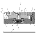
- FIG. 2 is a cross-sectional view taken along line AA of FIG. 1 regarding the IC socket.
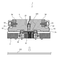
- FIG. 3 is a cross-sectional view taken along line BB in FIG. 1 regarding the IC socket.
- FIG. 4 is sectional drawing which shows the open state of FIG. 4 regarding the IC socket.
- FIG. drawing which shows the whole accommodation unit of the IC socket.
- It is a fragmentary sectional view which shows the detail of the accommodation unit of the IC socket.
- the electrical component socket is an IC socket 1 that electrically connects the IC package 100 and the wiring substrate 200 by accommodating the IC package 100 that is an electrical component and being fixed to the wiring substrate 200, for example, a burn-in test.
- the IC package 100 is used for an energization test under a temperature rise.
- the IC package 100 accommodated in the IC socket 1 has a hemispherical terminal 100b in a matrix shape on the bottom surface 100a of the substantially rectangular package body in plan view as shown in FIG.
- the IC package is a BGA (Ball Grid Array) format in which a plurality of arrays and the upper surface 100c of the package body are substantially flat.
- the present invention is not limited to the BGA type IC package, and the present invention may be applied to other types of IC packages such as an LGA (Land Grid Array) type IC package in which a large number of planar electrode pads are arranged on the bottom surface of the package body. Can be applied.
- the IC socket 1 includes a socket body 2 that houses the IC package 100 and is fixed to the wiring board 200, and a socket cover 3 that is rotatably attached to the socket body 2.
- the heat transfer member 4 that transfers heat to and from the IC package 100 and the lock mechanism 5 that fixes the socket cover 3 are provided.
- the socket body 2 has a substantially rectangular parallelepiped outer shape, and when one surface is fixed facing the wiring substrate 200, the IC package 100 starts from the surface opposite to the surface facing the wiring substrate 200 (accommodating surface 2a). To accommodate.
- the socket main body 2 is provided with a first rotation axis X1 at one end on the receiving surface 2a, and at the other end opposite to the one end, substantially parallel to the first rotation axis X1. Two rotation axes X2 are provided.
- the socket body 2 is formed with a notch 2b penetrating in a direction from the accommodation surface 2a toward the wiring board 200 between the first rotation axis X1 and the second rotation axis X2, and this notch 2b.
- the housing unit 10 disposed in the housing accommodates the IC package 100 with the upper surface 100c of the IC package 100 appearing on the housing surface 2a side of the socket body 2.
- the accommodation unit 10 includes the floating plate 12 that accommodates the IC package 100 in order in the direction from the accommodation surface 2 a toward the wiring substrate 200 and can move in parallel with the wiring substrate 200. And a contact pin array 16 in which a plurality of conductive contact pins 14 are arrayed between the floating plate 12 and the wiring board 200.
- the floating plate 12 is a plate-like electrical insulator that accommodates the IC package 100 so that the bottom surface 100a comes into contact therewith.
- the floating plate 12 is formed with a through hole 12a toward the wiring substrate 200 at a position corresponding to the hemispherical terminal 100b, and the hemispherical terminal 100b protrudes into the through hole 12a.
- the floating plate 12 is moved away from the wiring board 200 by the elastic member 12b interposed between the floating plate 12 and the contact pin array 16 when the parallel movement toward the wiring board 200 is started. Be energized.
- the contact pin 14 has a first straight portion 14a whose tip contacts a predetermined hemispherical terminal 100b of the IC package 100, a second straight portion 14b whose tip contacts a predetermined electrode (not shown) of the wiring board 200, Between the 1 straight part 14a and the 2nd straight part 14b, it has the spring part 14c curved, for example in S shape.
- the contact pin 14 is sandwiched between the hemispherical terminal 100b of the IC package 100 and a predetermined electrode of the wiring substrate 200, and a compressive force is applied, so that the first straight portion 14a and the first linear portion 14a
- the two straight portions 14b approach each other and the spring portion 14c is elastically deformed.
- the contact pin 14 is connected between the first straight portion 14a and the hemispherical terminal 100b of the IC package 100 and between the second straight portion 14b and a predetermined electrode of the wiring board 200 by a restoring force against the elastic deformation of the spring portion 14c.
- the IC package 100 and the wiring board 200 are electrically connected while generating a predetermined range of contact pressure therebetween.
- the contact pin 14 In the state where the compression force is not applied to the elastic member 12 b interposed between the floating plate 12 and the contact pin array 16, the contact pin 14 has the first straight portion 14 a connected to the hemispherical terminal 100 b of the IC package 100. Dimensions and shape are set so as not to touch.
- the contact pin array 16 is formed of an electrically insulating material including a first facing surface 16a facing the floating plate 12 and a second facing surface 16b facing the wiring board 200, and the first facing surface 16a has a first straight line.
- the first opposing surface 16a and the second opposing surface 16b The spring portion 14c is positioned in the space V between the two.
- the first insertion hole 16c positions the first straight portion 14a so that the first straight portion 14a contacts the predetermined hemispherical terminal 100b of the IC package 100 through the through hole 12a.
- the second insertion hole 16d positions the second straight portion 14b so that the second straight portion 14b contacts a predetermined electrode of the wiring board 200. Further, when the contact pin 14 is sandwiched between the hemispherical terminal 100b of the IC package 100 and a predetermined electrode of the wiring substrate 200 and a compressive force is applied, the first straight portion 14a is slid in the first insertion hole 16c. The second linear portion 14b is supported while sliding in the second insertion hole 16d.
- the socket cover 3 has a base end portion 3a that is pivotally supported by the first rotation axis X1 of the socket body 2, and a tip end portion 3b extending from the base end portion 3a is Then, from the state in which the socket cover 3 is opened (hereinafter referred to as “open state”), the socket cover 3 is rotated around the first rotation axis X1 and tilted toward the socket body 2 (second rotation axis X2). In other words, when the socket cover 3 is closed (hereinafter referred to as “closed state”), it is configured to be engaged with a later-described latch member attached to the socket body 2.
- the socket cover 3 has, for example, a configuration in which one end portion of the torsion spring 3c extrapolated to the first rotation axis X1 is locked to the socket cover 3 and the other end portion is locked to the socket body 2. When the socket cover 3 is closed, it is biased in the opposite direction, that is, in the opening direction.
- the heat transfer member 4 is pivotally supported on the third rotation axis X3 so as to be attached to the socket cover 3, and when the socket cover 3 is closed, the heat transfer member faces the upper surface 100c of the IC package 100. It has a surface (contact surface) 4a.
- the heat transfer surface 4 a is in contact with the upper surface 100 c of the IC package 100 in parallel with the heat transfer member 4 being rotatably attached to the socket body 2.
- the heat transfer member 4 has a heater (not shown) whose output can be controlled by an external control device, and can be controlled in temperature by having a heat radiation fin 4b on the outer surface, and the heat transfer surface 4a is the upper surface of the IC package 100. When it comes into contact with 100c, heat is transferred to and from the IC package 100 through the heat transfer surface 4a.
- the heater drive circuit may be provided in an external control device, the IC socket 1 or any other device.
- the lock mechanism 5 includes a lever member 5a pivotally supported on the second rotation axis X2 and the socket body 2 so as to be locked to the tip 3b of the socket cover 3 when the socket cover 3 is closed.
- a latch member that is attached to the other side end and is configured to move in a direction toward the socket body 2 via a cam mechanism (not shown) by rotating the lever member 5a around the second rotation axis X2. 5b.
- the lock mechanism 5 is configured such that when the heat transfer member 4 is moved by the movement of the latch member 5b, the heat transfer member 4 presses the upper surface 100c of the IC package 100 and moves the floating plate 12 to a predetermined position. Further, the lock mechanism 5 restricts the operation of the lever member 5a and fixes the socket cover 3 when the heat transfer member 4 presses the upper surface 100c of the IC package 100 and moves the floating plate 12 to a predetermined position. Configured to be locked. That is, the lock mechanism 5 can change the socket cover 3 from a simple closed state to a locked state.
- the heat transfer surface 4 a of the heat transfer member 4 faces the heat transfer surface 4 a and the upper surface 100 c of the IC package 100 in the closed state.
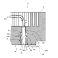
- An opening 18 penetrating in the opposite direction is formed, and a temperature sensor 20 for detecting the temperature of the IC package 100 is disposed inside the opening 18.
- the temperature sensor 20 includes a temperature sensing element 20a for detecting temperature and an electric conducting wire 20b connected to the temperature sensing element.
- the temperature sensing element 20a is built in and fixed to a tip portion 20c of a linearly extending rod-like body. It is led out from the rear end 20d through the inside of the rod-shaped body.
- various temperature detection means such as a resistance temperature detector using the temperature dependence of the electrical resistance of a metal, a thermocouple using the Seebeck effect, or a thermistor can be used. It should be noted that the temperature sensing element 20a of the temperature sensor 20 does not matter whether it is exposed on the tip end surface 20e of the rod-shaped body as long as it does not interfere with temperature detection of the IC package 100.
- the rod-shaped body may be formed of any material such as metal, nonmetal, and resin.
- the rod-shaped body is a concept that includes both solid bodies such as columns and prisms, and hollow bodies (tubular bodies) such as cylinders and square tubes.
- the heat transfer member 4 has a support structure that supports the temperature sensor 20 at a portion other than the tip portion 20c of the temperature sensor 20.
- a support structure is a fitting structure F in which the outer surface of a portion (for example, the rear end portion 20d) excluding the front end portion 20c of the temperature sensor 20 is slidably fitted in the axial direction of the temperature sensor 20 in this embodiment.
- the heat transfer member 4 is configured as a separate cylindrical part 22.
- the cylindrical component 22 is a heat insulating component made of a heat insulating material so as to cut off heat transfer between the portion excluding the tip 20c of the temperature sensor 20 and the heat transfer member 4 as much as possible.
- a part of the temperature sensor 20 excluding the tip part 20 c is formed by retreating a part of the inner surface of the insertion hole 22 a that slides with the outer surface of the part excluding the tip part 20 c of the temperature sensor 20.
- the heat transfer between the temperature sensor 20 and the heat transfer member 4 may be reduced by reducing the contact area between the temperature sensor 20 and the tubular part 22.
- the temperature sensor 20 is formed to protrude from the outer surface of the temperature sensor 20 at a portion excluding the tip portion 20c and a sliding portion that slides on the inner surface of the insertion hole 22a of the cylindrical part 22, for example, a flange-shaped protrusion. It has a portion 20f. Then, when the temperature sensor 20 moves toward the IC package 100, the heat transfer member 4 has a step 4c that is locked by the protruding portion 20f and is restricted from moving from the cylindrical component 22 to the heat transfer surface 4a. On the inner surface of the opening 18.
- the step 4 c is a step structure D that suppresses the temperature sensor 20 from falling off the opening 18.
- the inner surface of the opening 18 and the protruding portion 20f are not in contact with the inner surface of the opening 18 and the protruding portion 20f except for the step 4c so as to cut off heat transfer between the temperature sensor 20 and the heat transfer member 4 as much as possible. Dimensions and shape are set.
- the IC socket 1 accommodates the IC package 100 and is fixed to the wiring board 200. With this, the IC package 100 and the wiring board 200 are electrically connected to each other, for example, in a burn-in test or the like, An energization test is performed. In such an energization test, as shown in FIG. 11, the IC socket 1 is electrically connected to an external control device 300, and the external control device 300 inputs an output signal of the temperature sensor 20 and heat transfer member. An instruction signal can be output to the heater drive circuit of 4.
- the bottom surface 100a of the IC package 100 is in contact with the socket cover 3 and the lever member 5a of the IC socket 1 being opened. Is housed in the floating plate 12 of the housing unit 10 (see FIGS. 7 and 8).
- the arrangement of the temperature sensor 20 with respect to the opening 18 of the heat transfer member 4 is performed as follows. That is, in the state where the spring 24 is extrapolated from the rear end portion 20d of the temperature sensor 20 toward the projecting portion 20f, the temperature sensor is arranged with the tip end portion 20c first from the side opposite to the heat transfer surface 4a of the heat transfer member 4. 20 is inserted into the opening 18. Then, the tubular member 22 is mounted in the opening 18 in a state where the rear end portion 20 d of the temperature sensor 20 is fitted into the insertion hole 22 a of the tubular part 22 while passing the electric conductor 20 b of the temperature sensor 20. Thereby, the temperature sensor 20 is arranged with respect to the opening 18 of the heat transfer member 4.
- the protrusion 20f of the temperature sensor 20 is locked to the step 4c of the step structure D, thereby preventing the temperature sensor 20 from dropping from the heat transfer surface 4a side of the opening 18. is doing.
- the temperature sensor 20 is disposed inside the opening 18 of the heat transfer member 4, the protruding portion 20 f of the temperature sensor 20 is pressed against the step 4 c of the step structure D by the urging force of the spring 24 when the socket cover 3 is open.
- the tip 20c of the temperature sensor 20 protrudes from the heat transfer surface 4a.
- the lever member 5a of the lock mechanism 5 is rotated around the second rotation axis X2 to lock the socket cover 3, and the heat transfer member 4 causes the upper surface 100c of the IC package 100 to move.
- the floating plate 12 is moved to a predetermined position (see FIGS. 2 and 5).
- the tip portion 20c of the temperature sensor 20 protruding from the heat transfer surface 4a as shown in FIG.
- the sensor 20 moves backward until the tip surface 20e of the temperature sensor 20 is flush with the heat transfer surface 4a against the elastic force of the spring 24 (see FIG. 12).
- the front end surface 20e of the temperature sensor 20 comes into contact with the upper surface 100c of the IC package 100 with an appropriate pressure due to the restoring force of the spring 24, so that a temperature close to the actual temperature of the IC package 100 can be easily detected. Will improve.
- the temperature sensor 20 retreats while the outer surface of the portion excluding the tip 20c of the temperature sensor 20 slides with the inner surface of the insertion hole 22a of the cylindrical part 22.
- the axial direction of the temperature sensor 20 remains coincident with the facing direction in which the heat transfer surface 4a and the upper surface 100c of the IC package 100 face each other in the closed state. Therefore, when the temperature sensor 20 moves backward, the tip portion 20c hardly swings and remains separated from the inner surface of the opening 18, so that the air layer G is maintained between the inner surface of the opening 18 and the tip portion 20c. Has been.
- the ambient temperature of the IC socket 1 is raised to the test temperature, and the IC package 100 and the wiring board 200 are energized through the IC socket 1.
- the external control device 300 determines the actual temperature of the IC package 100 based on the detected temperature of the IC package 100 detected by the temperature sensor 20 through feedback control such as PID (Proportional-Integral-Differential) control.
- PID Proportional-Integral-Differential
- the output of the heater of the heat transfer member 4 is controlled so as to approach the temperature.
- the electrical component socket accommodates the IC package 100 that is an electrical component and is fixed to the wiring board 200, thereby electrically connecting the IC package 100 and the wiring board 200.
- the IC socket 1 ⁇ / b> A has a fitting structure F in which the outer surface of the portion (for example, the rear end portion 20 d) except the tip portion 20 c of the temperature sensor 20 is slidably fitted in the axial direction of the temperature sensor 20. It differs from the IC socket 1 of the first embodiment in that it is integrally molded. That is, in the IC socket 1 ⁇ / b> A, the portion excluding the tip end portion 20 c of the temperature sensor 20 is fitted, and the insertion hole 4 d through which the electric conductor 20 b of the temperature sensor 20 is inserted is directly formed in the heat transfer member 4. For example, the insertion hole 4d is formed by projecting the inner surface of the opening 18 opposite to the heat transfer surface 4a side inward.
- the step structure D that suppresses this is formed by a tubular part 26 that is separate from the heat transfer member 4.
- the cylindrical part 26 has an insertion hole 26a through which the temperature sensor 20 is inserted in the axial direction.
- the circular outer periphery of the cylindrical part 26 is screwed into the circular inner periphery of the opening 18, and the like.
- the temperature sensor 20 is attached to the inner surface of the opening 18 so as to coincide with the axial direction.
- An end surface 26 b opposite to the heat transfer surface 4 a side of the cylindrical component 26 attached to the inner surface of the opening 18 forms a step structure D in the axial direction with respect to the inner surface of the opening 18.
- the protruding portion 20 f of the temperature sensor 20 is locked to the end surface 26 b of the cylindrical part 26 from the insertion hole 4 d side, and the temperature The sensor 20 is prevented from dropping from the opening 18.
- the inner surface of the insertion hole 26 a of the cylindrical part 26 is formed so as to be separated from the outer surface of the temperature sensor 20.
- the arrangement of the temperature sensor 20 with respect to the opening 18 of the heat transfer member 4 is performed as follows. That is, in the state where the spring 24 is extrapolated from the rear end portion 20d of the temperature sensor 20 toward the protruding portion 20f, the temperature sensor 20 from the heat transfer surface 4a side of the heat transfer member 4 with the rear end portion 20d first. Is inserted into the opening 18, and the rear end portion 20 d is fitted into the insertion hole 4 d of the heat transfer member 4 through the electric conductor 20 b of the temperature sensor 20.
- the temperature sensor 20 moves backward until the front end surface 20e is flush with the heat transfer surface 4a (the state shown in FIG. 13). Since the outer surface is supported while sliding with the inner surface of the insertion hole 4 d of the heat transfer member 4, the axial direction of the temperature sensor 20 is opposed to the heat transfer surface 4 a facing the upper surface 100 c of the IC package 100 in the closed state. It remains consistent with the direction. Therefore, when the temperature sensor 20 moves backward, the tip end portion 20c hardly swings and remains separated from the inner surface of the insertion hole 26a of the cylindrical component 26, so that there is no gap between the inner surface of the insertion hole 26a and the tip end portion 20c. The air layer G is maintained.
- the heat transfer member 4 is integrally formed with the fitting structure F in which the outer surface of the portion excluding the tip 20c of the temperature sensor 20 is slidably fitted in the axial direction of the temperature sensor 20. ing.
- the tubular part 26, which is separate from the heat transfer member 4 is formed as a step structure D that suppresses the drop-off of the temperature sensor 20 from the heat transfer surface 4 a side.
- the inner surface of the insertion hole 26a of the cylindrical part 26 is formed so as to be separated from the outer surface of the temperature sensor 20 via the air layer G.
- the electrical component socket according to the third embodiment accommodates the IC package 100 that is an electrical component and is fixed to the wiring board 200, so that the IC package 100 and the wiring board 200 are connected.
- the IC socket 1B is electrically connected.
- the IC socket 1B has a fitting structure F (cylindrical component 22) in which the outer surface of the portion excluding the tip 20c of the temperature sensor 20 is slidably fitted in the axial direction of the temperature sensor 20 and the tip surface 20e of the temperature sensor 20.
- the two configurations of the first embodiment including the elastic body (spring 24) that urges the protruding portion 20f toward the IC package 100 in a state where the projection 20f is in contact with the upper surface 100c of the IC package 100 are made of, for example, a resin material or the like. It differs from 1st Embodiment by the point comprised by the one heat insulating spring 28 formed.
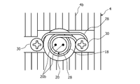
- the heat insulating spring 28 extends through the opening 18 from one end fixed to the heat transfer member 4 with a fixing tool 30 such as a bolt to the other end contacting the protruding portion 20 f of the temperature sensor 20 disposed inside the opening 18. It extends without contacting the inner surface of the opening 18.
- the heat insulating spring 28 is externally fitted to a portion of the temperature sensor 20 excluding the tip portion 20c, and biases the temperature sensor 20 toward the IC package 100.
- the size and shape of the inner peripheral surface of the heat insulating spring 28 are set so as to be slidably fitted in the axial direction of the temperature sensor 20 with the outer surface of the temperature sensor 20 excluding the tip 20c.
- the temperature sensor 20 moves backward until the front end surface 20e is flush with the heat transfer surface 4a, but the outer surface of the portion excluding the front end 20c of the temperature sensor 20 is the heat insulating spring 28. Therefore, the axial direction of the temperature sensor 20 remains coincident with the facing direction in which the heat transfer surface 4a and the upper surface 100c of the IC package 100 face each other in the closed state. Therefore, when the temperature sensor 20 moves backward, the tip portion 20c hardly swings and remains separated from the inner surface of the opening 18, so that the air layer G is maintained between the inner surface of the opening 18 and the tip portion 20c. Has been.
- the fitting structure F in which the outer surface of the portion excluding the tip 20c of the temperature sensor 20 is slidably fitted in the axial direction of the temperature sensor 20 and the tip 20c of the temperature sensor 20 are provided.
- the two heat-insulating springs 28 realize the two configurations of the first embodiment including the elastic body that urges the protruding portion 20 f toward the IC package in a state of being in contact with the IC package 100.
- the tip portion 20c of the temperature sensor 20 is in contact with the IC package 100 and is separated via the heat transfer member 4 and the air layer G, the heat transfer member 4 and temperature Heat transfer due to contact with the tip 20c of the sensor 20 through the solid is reduced, and the temperature sensing element 20a of the tip 20c is less likely to be thermally affected by the heat transfer member 4. Accordingly, the temperature detection accuracy of the IC package 100 by the temperature sensor 20 can be improved while reducing the number of parts of the IC socket 1.
- the fitting structure F is configured by the cylindrical part 22 that is separate from the heat transfer member 4, and the step structure D is directly formed as a step 4 c on the inner surface of the opening 18 of the heat transfer member 4.
- the fitting structure F was directly formed in the heat-transfer member 4 as the insertion hole 4d, and the level
- the fitting structure F is configured by a separate cylindrical part 22 from the heat transfer member 4, and the step structure D is formed separately from the heat transfer member 4. You may comprise by the cylindrical component 26.
- the outer surface of the portion excluding the tip portion 20 c of the temperature sensor 20 is the axis of the temperature sensor 20.
- the fitting structure F which is slidably fitted in the direction was used.
- a portion excluding the front end portion 20c of the temperature sensor 20 (for example, the rear end portion 20d) is used as a support structure.
- a structure that is fixed to the insertion hole 22a of the cylindrical part 22 or the insertion hole 4d of the heat transfer member 4 may be employed.
- the temperature sensor 20 has a shaft inside the insertion hole 22 a of the tubular part 22, the insertion hole 4 d of the heat transfer member 4, or the heat insulating spring 28.
- the protrusion 20f of the temperature sensor 20 may be formed intermittently around the axis instead of being continuously formed around the entire axis of the temperature sensor 20.
- the step structure D is also provided on the inner surface of the opening 18 so that the protruding portion 20f formed intermittently around the axis is locked in the axial direction. It may be formed intermittently. Thereby, the heat transfer by the contact through the solid of the temperature sensor 20 and the heat-transfer member 4 can be reduced.
Landscapes
- Physics & Mathematics (AREA)
- General Physics & Mathematics (AREA)
- Engineering & Computer Science (AREA)
- Computer Hardware Design (AREA)
- Microelectronics & Electronic Packaging (AREA)
- Environmental & Geological Engineering (AREA)
- Health & Medical Sciences (AREA)
- Toxicology (AREA)
- General Engineering & Computer Science (AREA)
- Testing Of Individual Semiconductor Devices (AREA)
- Connecting Device With Holders (AREA)
Abstract
電気部品(100)と当接可能にソケット本体に取り付けられ、ソケット本体に収容された電気部品(100)と当接する当接面(4c)に貫通形成された開口(18)を有する伝熱部材(4)と、伝熱部材(4)の開口(18)の内部において、感温素子を含む先端部(20c)が電気部品(100)に向けて棒状に延び、先端部(20c)が伝熱部材(4)とともに電気部品(100)と当接する温度センサ(20)と、を備えるICソケット(1)において、開口(18)には、温度センサ(20)の先端部(20c)を除く部分の外面が温度センサ(20)の軸方向で摺動自在に嵌合する挿通孔(22a)を備えた筒状部品(22)が取り付けられる。これにより、温度センサ(20)の軸方向における移動を可能にしつつ、温度センサ(20)の先端部(20c)が揺動して開口(18)の内面と接触しないように、温度センサ(20)を支持する。
Description
本発明は、電気部品を収容して配線基板に固定されることで、電気部品と配線基板とを電気的に接続する電気部品用ソケットに関し、特に、電気部品の温度を検出する温度センサを備えた電気部品用ソケットに関する。
従来の電気部品用ソケットには、電気部品として、例えばIC(Integrated Circuit)パッケージを収容して、このICパッケージと配線基板とを電気的に接続し、昇温下で通電試験を行うICソケットが知られている(例えば、特許文献1参照)。
かかるICソケットでは、温度制御可能な伝熱部材と温度センサとをICパッケージに接触させ、温度センサで検出されたICパッケージの検出温度に応じて伝熱部材の温度を制御することで、ICパッケージの実際の温度を所定温度に近づけて均一な試験条件となるようにしているが、温度センサが伝熱部材から受ける熱的影響を低減するために、温度センサと伝熱部材との間に断熱材を介在させている。
しかしながら、温度センサは、断熱材に含まれる固体部分を介して伝熱部材から熱的影響を受け得るため、温度センサの検出温度とICパッケージの実際の温度との間に誤差が生じる可能性がある。
そこで、本発明は、このような問題点に対処し、温度センサによる電気部品の温度の検出精度を向上可能な電気部品用ソケットを提供することを目的とする。
かかる課題を解決するために、本発明による電気部品用ソケットは、電気部品を収容するソケット本体と、電気部品と当接可能にソケット本体に取り付けられ、電気部品と当接する当接面に貫通形成された開口を有する伝熱部材と、伝熱部材の開口の内部において、感温素子を含む先端部が電気部品に向けて棒状に延び、先端部が伝熱部材とともに電気部品と当接する温度センサと、を備えるものであって、温度センサの先端部を除く部分で温度センサを支持する支持構造を有し、先端部が電気部品に当接した状態で伝熱部材と空気層を介して離間している。
本発明の電気部品用ソケットによれば、伝熱部材と温度センサの先端部との間における固体部分を介した熱伝達が減少するため、先端部の感温素子が伝熱部材から熱的影響を受け難くなり、温度センサによる電気部品の温度の検出精度を向上させることができる。
以下、添付された図面を参照し、本発明を実施するための実施形態について詳述する。
図1~図6は、第1実施形態に係る電気部品用ソケットの一例を示す。
電気部品用ソケットは、電気部品であるICパッケージ100を収容して配線基板200に固定されることで、ICパッケージ100と配線基板200とを電気的に接続するICソケット1であり、例えばバーンイン試験等、昇温下におけるICパッケージ100の通電試験に用いられる。
図1~図6は、第1実施形態に係る電気部品用ソケットの一例を示す。
電気部品用ソケットは、電気部品であるICパッケージ100を収容して配線基板200に固定されることで、ICパッケージ100と配線基板200とを電気的に接続するICソケット1であり、例えばバーンイン試験等、昇温下におけるICパッケージ100の通電試験に用いられる。
なお、以下の説明において、ICソケット1に収容されるICパッケージ100は、一例として、図16に示されるように、平面視で略矩形のパッケージ本体の底面100aに半球状端子100bがマトリックス状に複数配列され、パッケージ本体の上面100cが略平坦なBGA(Ball Grid Array)形式のICパッケージであるものとする。ただし、BGA形式のICパッケージに限らず、例えば、パッケージ本体の底面に多数の平面電極パッドを並べたLGA(Land Grid Array)形式のICパッケージ等、他の形式のICパッケージであっても本発明の適用が可能である。
図1~図6に示されるように、ICソケット1は、ICパッケージ100を収容して配線基板200に固定されるソケット本体2と、ソケット本体2に回動自在に取り付けられたソケットカバー3と、ICパッケージ100との間で熱伝達を行う伝熱部材4と、ソケットカバー3を固定するロック機構5と、を備えている。
ソケット本体2は、略直方体状の外形を有し、一面が配線基板200に対向して固定されたときに、配線基板200と対向する面の反対側の面(収容面2a)からICパッケージ100を収容する。ソケット本体2には、収容面2aにおいて、一側端部に第1回動軸X1が設けられ、一側端部と反対側の他側端部に第1回動軸X1と略平行に第2回動軸X2が設けられている。
また、ソケット本体2には、第1回動軸X1と第2回動軸X2との間において、収容面2aから配線基板200に向かう方向に貫通する切欠部2bが形成され、この切欠部2bに配設された収容ユニット10により、ICパッケージ100の上面100cがソケット本体2の収容面2a側に表れた状態で収容される。
図7及び図8に示されるように、収容ユニット10は、収容面2aから配線基板200に向かう方向で、順に、ICパッケージ100を収容して配線基板200に対し平行移動可能なフローティングプレート12と、フローティングプレート12と配線基板200との間に導電性の複数のコンタクトピン14を配列したコンタクトピン配列体16と、を含んでいる。
フローティングプレート12は、ICパッケージ100を底面100aが当接するように収容する板状の電気絶縁体である。フローティングプレート12には、半球状端子100bに対応する位置に配線基板200に向かう貫通孔12aが形成され、この貫通孔12aの内部に半球状端子100bが突出する。
また、フローティングプレート12は、配線基板200に向けて平行移動を開始したときに、フローティングプレート12とコンタクトピン配列体16との間に介装された弾性部材12bによって、配線基板200から離れる方向へ付勢される。
コンタクトピン14は、ICパッケージ100の所定の半球状端子100bに先端が接触する第1直線部14aと、配線基板200の所定電極(図示省略)に先端が接触する第2直線部14bと、第1直線部14aと第2直線部14bとの間において、例えばS字状に湾曲したバネ部14cと、を有している。コンタクトピン14は、フローティングプレート12が所定位置にあるときに、ICパッケージ100の半球状端子100bと配線基板200の所定電極とに挟まれて圧縮力を加えられて、第1直線部14aと第2直線部14bとが互いに接近してバネ部14cが弾性変形する。そして、コンタクトピン14は、バネ部14cの弾性変形に対する復元力によって、第1直線部14aとICパッケージ100の半球状端子100bとの間及び第2直線部14bと配線基板200の所定電極との間に所定範囲の接触圧を生じさせつつ、ICパッケージ100と配線基板200とを電気的に接続する。
コンタクトピン14は、フローティングプレート12とコンタクトピン配列体16との間に介装された弾性部材12bに圧縮力が働いていない状態では、第1直線部14aがICパッケージ100の半球状端子100bと接触しないように寸法・形状が設定されている。
コンタクトピン配列体16は、フローティングプレート12に対向する第1対向面16aと配線基板200に対向する第2対向面16bとを含む電気絶縁材料で形成され、第1対向面16aには第1直線部14aが挿通する第1挿通孔16cを有し、第2対向面16bには第2直線部14bが挿通する第2挿通孔16dを有し、第1対向面16aと第2対向面16bとの間の空間Vにバネ部14cを位置させている。第1挿通孔16cは、第1直線部14aがICパッケージ100の所定の半球状端子100bと貫通孔12aを通して接触するように第1直線部14aを位置決めしている。第2挿通孔16dは、第2直線部14bが配線基板200の所定電極と接触するように第2直線部14bを位置決めしている。また、コンタクトピン14がICパッケージ100の半球状端子100bと配線基板200の所定電極とに挟まれて圧縮力を加えられたとき、第1挿通孔16cでは第1直線部14aが摺動しつつ支持され、第2挿通孔16dでは第2直線部14bが摺動しつつ支持される。
再び図1~図6を参照して、ソケットカバー3は、ソケット本体2の第1回動軸X1に軸支される基端部3aを有し、基端部3aから延びた先端部3bは、ソケットカバー3が開いた状態(以下、「開状態」という)から、ソケットカバー3を第1回動軸X1周りに回動させてソケット本体2(第2回動軸X2)に向けて倒したときに、すなわち、ソケットカバー3を閉じたとき(以下、「閉状態」という)に、ソケット本体2に取り付けられた後述のラッチ部材と係止するように構成されている。
ソケットカバー3は、例えば、第1回動軸X1に外挿されたトーションばね3cの一端部がソケットカバー3に係止され、他端部がソケット本体2に係止される等の構成により、ソケットカバー3を閉じたときに、反対方向すなわち開く方向に付勢される。
また、ソケットカバー3は、基端部3aと先端部3bとの間で伝熱部材4を取り付けるための枠構造3dを有し、この枠構造3dには、第1回動軸X1と略平行な第3回動軸X3が設けられている。
伝熱部材4は、第3回動軸X3に回動自在に軸支されることでソケットカバー3に取り付けられ、ソケットカバー3を閉じたときに、ICパッケージ100の上面100cと対向する伝熱面(当接面)4aを有している。伝熱面4aは、伝熱部材4がソケット本体2に回動自在に取り付けられていることで、ICパッケージ100の上面100cと平行に当接する。
また、伝熱部材4は、外部の制御装置によって出力制御可能なヒータ(図示省略)を有するとともに外面に放熱フィン4bを有することで温度制御可能であり、伝熱面4aがICパッケージ100の上面100cと当接したときに、伝熱面4aを介してICパッケージ100との間で熱伝達を行う。なお、ヒータの駆動回路は、外部の制御装置若しくはICソケット1又はその他のいずれに備えていてもよい。
ロック機構5は、第2回動軸X2に回動自在に軸支されたレバー部材5aと、ソケットカバー3を閉じたときにソケットカバー3の先端部3bに係止されるようにソケット本体2の他側端部に取り付けられ、レバー部材5aを第2回動軸X2周りに回動させることで図示省略のカム機構を介してソケット本体2に向かう方向へ移動するように構成されたラッチ部材5bと、を備えている。
ソケットカバー3をラッチ部材5bに係止した状態(閉状態)でレバー部材5aを回動させたときに、ラッチ部材5bがソケット本体2に向けて移動することで、ソケットカバー3の微小回動とともに伝熱部材4がソケット本体2に向けてさらに移動する。ロック機構5は、ラッチ部材5bの移動による伝熱部材4の移動によって、伝熱部材4がICパッケージ100の上面100cを押圧してフローティングプレート12を所定位置まで移動するように構成される。また、ロック機構5は、伝熱部材4がICパッケージ100の上面100cを押圧してフローティングプレート12を所定位置まで移動したときに、レバー部材5aの動作が制限されてソケットカバー3が固定されるロック状態となるように構成される。すなわち、ロック機構5によりソケットカバー3を単なる閉状態からロック状態まで変化させることができる。
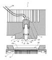
ここで、図1及び図4~6に加えて、特に図9を参照すると、伝熱部材4の伝熱面4aには、閉状態で伝熱面4aとICパッケージ100の上面100cとが対向する対向方向に貫通する開口18が形成され、この開口18の内部に、ICパッケージ100の温度を検出するための温度センサ20が配置される。
温度センサ20は、温度を検知する感温素子20aとこれに接続された電気導線20bとを含み、直線的に延びる棒状体の先端部20cに感温素子20aを内蔵固定し、電気導線20bが棒状体の内部を通って後端部20dから導出されて構成されている。温度センサ20としては、例えば、金属の電気抵抗の温度依存性を利用した測温抵抗体、ゼーベック効果を利用した熱電対、又はサーミスタ等、種々の温度検出手段を用い得る。なお、温度センサ20の感温素子20aは、ICパッケージ100の温度検出に支障がなければ、棒状体の先端面20eに露出しているか否かは問わない。また、棒状体は、金属・非金属・樹脂等のいずれの材料で形成されてもよい。さらに、棒状体は、円柱、角柱等の中実体、及び円筒、角筒等の中空体(管状体)のいずれも含む概念である。
温度センサ20は、伝熱部材4の開口18の内部において、先端面20eがICパッケージ100の上面100cに当接するように、先端部20cをICパッケージ100に向け、かつ、後端部20dをその反対方向に向けて配置される。すなわち、温度センサ20は、伝熱部材4の開口18の内部において、温度センサ20の軸方向が伝熱面4a及び上面100cの対向方向と一致するように配置される。
伝熱部材4において、開口18の大きさは、温度センサ20が開口18の内部に配置された状態で、温度センサ20の軸方向と直交する方向において温度センサ20の外面と開口18の内面との間に隙間ができるように設定されている。特に、伝熱部材4は、開口18の内面が温度センサ20の先端部20cの外面から離間して形成される。
また、伝熱部材4は、温度センサ20の先端部20cを除く部分で温度センサ20を支持する支持構造を有している。かかる支持構造は、本実施形態において、温度センサ20の先端部20cを除く部分(例えば後端部20d)の外面が温度センサ20の軸方向で摺動自在に嵌合する嵌合構造Fであり、伝熱部材4と別体の筒状部品22として構成されている。
筒状部品22は、温度センサ20の先端部20cを除く部分が嵌合し、温度センサ20の電気導線20bが挿通する挿通孔22aを軸方向に有し、例えば、筒状部品22の円形外周を開口18の円形内周に螺合させる等、伝熱部材4のうち伝熱面4aと反対側から、温度センサ20と軸方向を一致させて開口18内に取り付けられる。挿通孔22aは、温度センサ20の先端部20cを除く部分の外面と温度センサ20の軸方向で摺動自在に嵌合し、かつ、筒状部品22が開口18内に取り付けられた状態で、温度センサ20の外面が開口18の内面と離間するように、寸法・形状・位置が設定されている。これにより、筒状部品22は、温度センサ20の軸方向における移動を可能にしつつ、温度センサ20の先端部20cが揺動して開口18の内面と接触しないように、温度センサ20を支持している。
なお、筒状部品22は、温度センサ20の先端部20cを除く部分と伝熱部材4との間の熱伝達を極力遮断すべく、断熱材で構成された断熱部品とすることが好ましい。
また、図10に示すように、温度センサ20の先端部20cを除く部分の外面と摺動する挿通孔22aの内面を一部外方に後退させて、温度センサ20の先端部20cを除く部分と筒状部品22との接触面積を減少させ、温度センサ20と伝熱部材4との間における熱伝達を低減するようにしてもよい。
温度センサ20は、先端部20cと、筒状部品22の挿通孔22aの内面と摺動する摺動部と、を除く部分に、温度センサ20の外面から突出形成された、例えばフランジ状の突出部20fを有している。そして、伝熱部材4は、温度センサ20がICパッケージ100に向けて移動したときに、突出部20fが係止して移動が規制される段差4cを、筒状部品22から伝熱面4aまでの開口18の内面に有している。段差4cは、温度センサ20が開口18から脱落することを抑制する段差構造Dである。
ただし、開口18の内面及び突出部20fは、温度センサ20と伝熱部材4との間の熱伝達を極力遮断すべく、開口18の内面と突出部20fとが段差4c以外では接触しないように寸法・形状が設定されている。
温度センサ20の突出部20fと筒状部品22との間において、温度センサ20にはスプリング24が外挿され、このスプリング24は、温度センサ20の先端部20c(先端面20e)がICパッケージ100の上面100cに当接すると、突出部20fのうち筒状部品22側の端面に当接するスプリング24の一端が、筒状部品22のうち突出部20f側の端面に当接するスプリング24の他端に向けて圧縮され、その弾性変形による復元力によって突出部20fをICパッケージ100に向けて付勢するように構成されている。
なお、温度センサ20の突出部20fと筒状部品22との間に介装され、温度センサ20の先端部20cがICパッケージに当接した状態で突出部20fをICパッケージ100に向けて付勢する弾性体のうち、弾性変形によって伝熱部材4の開口18の内面と接触するものでなければ、前述のスプリング24に限定されず、ゴム等の種々の弾性体を用い得る。また、スプリング24は金属製に限らず、非金属や、熱伝達率の比較的低い樹脂材料等も用い得る。
次に、ICソケット1の使用方法について説明する。
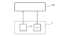
ICソケット1はICパッケージ100を収容して配線基板200に固定され、これによりICパッケージ100と配線基板200とを電気的に接続した状態で、例えばバーンイン試験等、昇温下におけるICパッケージ100の通電試験が行われる。かかる通電試験において、図11に示すように、ICソケット1は外部の制御装置300と電気的に接続され、外部の制御装置300は、温度センサ20の出力信号を入力し、かつ、伝熱部材4が有するヒータの駆動回路に対して指示信号を出力できるように構成されている。
ICソケット1はICパッケージ100を収容して配線基板200に固定され、これによりICパッケージ100と配線基板200とを電気的に接続した状態で、例えばバーンイン試験等、昇温下におけるICパッケージ100の通電試験が行われる。かかる通電試験において、図11に示すように、ICソケット1は外部の制御装置300と電気的に接続され、外部の制御装置300は、温度センサ20の出力信号を入力し、かつ、伝熱部材4が有するヒータの駆動回路に対して指示信号を出力できるように構成されている。
図1のうちICパッケージ100が表れている方、及び図2の破線で示すように、ICソケット1のソケットカバー3及びレバー部材5aを開いた状態で、ICパッケージ100を底面100aが当接するように収容ユニット10のフローティングプレート12に収容する(図7及び図8参照)。
図9を参照して、伝熱部材4の開口18に対する温度センサ20の配置は、次のようにして行われる。すなわち、温度センサ20の後端部20dから突出部20fに向けてスプリング24を外挿した状態で、伝熱部材4のうち伝熱面4aと反対側から、先端部20cを先にして温度センサ20を開口18に挿入する。そして、筒状部品22の挿通孔22aに温度センサ20の電気導線20bを通しつつ温度センサ20の後端部20dを嵌合させた状態で、筒状部材22を開口18内に取り付ける。これにより、伝熱部材4の開口18に対して温度センサ20が配置される。温度センサ20を開口18に挿入したとき、温度センサ20の突出部20fが段差構造Dの段差4cに係止することで、温度センサ20が開口18の伝熱面4a側から脱落することを抑制している。温度センサ20を伝熱部材4の開口18の内部に配置すると、ソケットカバー3が開いた状態では、スプリング24の付勢力により温度センサ20の突出部20fが段差構造Dの段差4cに押し付けられて、温度センサ20の先端部20cが伝熱面4aから突出している。
フローティングプレート12にICパッケージ100を収容した状態で、図6に示すように、ソケットカバー3を第1回動軸X1周りに回動させてソケット本体2に向けて倒し、先端部3bをソケット本体2のラッチ部材5bに係止させて、ソケットカバー3を閉状態とする。
ソケットカバー3を閉状態にした後、ロック機構5のレバー部材5aを第2回動軸X2周りに回動させてソケットカバー3をロック状態にし、伝熱部材4がICパッケージ100の上面100cを押圧することで、フローティングプレート12を所定位置まで移動させる(図2及び図5参照)。
フローティングプレート12が所定位置まで移動すると、伝熱部材4は、第1回動軸X1に略平行な第3回動軸X3に回動自在に軸支されているためICパッケージ100の上面100cと平行に当接する。このため、伝熱部材4からICパッケージ100に加えられる押圧力の圧力分布の偏りを緩和できるので、ICパッケージ100と伝熱部材4との熱伝達効率を向上させることができる。
また、フローティングプレート12が所定位置まで移動すると、コンタクトピン14は、ICパッケージ100の半球状端子100bと配線基板200の所定電極とに挟まれて圧縮力を加えられてバネ部14cが弾性変形し、その復元力によって、第1直線部14aとICパッケージ100の半球状端子100bとの間、及び第2直線部14bと配線基板200の所定電極との間に所定範囲の接触圧が生じる。これにより、第1直線部14aとICパッケージ100との間、及び第2直線部14bと配線基板200との間における電気抵抗を、試験結果に影響を与えない程度に抑制しつつ、ICパッケージ100と配線基板200とが電気的に接続される。
さらに、フローティングプレート12が所定位置まで移動する際、ICパッケージ100の上面100cには、図9に示すように伝熱面4aから突出している温度センサ20の先端部20cが最初に接触し、温度センサ20は、スプリング24の弾性力に抗して、温度センサ20の先端面20eが伝熱面4aと面一となるまで後退する(図12参照)。そして、スプリング24の復元力によって、温度センサ20の先端面20eがICパッケージ100の上面100cと適切な圧力で当接するので、ICパッケージ100の実際の温度に近い温度を検出しやすくなって検出精度が向上する。
また、図9及び図12に示されるように、温度センサ20は、温度センサ20の先端部20cを除く部分の外面が筒状部品22の挿通孔22aの内面と摺動しつつ後退するので、温度センサ20の軸方向は、閉状態で伝熱面4aとICパッケージ100の上面100cとが対向する対向方向と一致したままである。したがって、温度センサ20が後退する際、先端部20cは殆ど揺動せずに開口18の内面と離間したままであるので、開口18の内面と先端部20cとの間には空気層Gが維持されている。
この状態でICソケット1の周囲温度を試験温度まで昇温し、ICソケット1を介してICパッケージ100と配線基板200との間で通電を行う。
そして、外部の制御装置300は、温度センサ20により検出されたICパッケージ100の検出温度に基づいて、PID(Proportional-Integral-Differential)制御等のフィードバック制御によって、ICパッケージ100の実際の温度が所定温度に近づくように伝熱部材4のヒータの出力を制御する。
例えば、外部の制御装置300は、温度センサ20により検出されたICパッケージ100の検出温度が所定温度より低い場合に、伝熱部材4のヒータの出力を増大させ、伝熱部材4から伝熱面4aを通してICパッケージ100の温度を上昇させる。一方、外部の制御装置は、温度センサ20により検出されたICパッケージ100の検出温度が所定温度より高い場合に、伝熱部材4のヒータの出力を減少又は遮断するとともに、伝熱部材4がICパッケージ100の発熱を伝熱面4aから受けて、放熱フィン4bを介して周囲空気中へ放熱する。
このようなICソケット1によれば、温度センサ20の先端部20cを除く部分で温度センサ20を支持し、温度センサ20の先端部20cがICパッケージ100に当接した状態で伝熱部材4と空気層Gを介して離間している。したがって、伝熱部材4と温度センサ20の先端部20cとの間における固体を介した接触による熱伝達が減少するため、先端部20cの感温素子20aが伝熱部材4から熱的影響を受け難くなり、温度センサ20によるICパッケージ100の温度の検出精度を向上させることができる。
次に、図13を参照して、第2実施形態に係る電気部品用ソケットの一例を示す。なお、第1実施形態と共通の構成については、同一の符号を付してその説明を極力省略する。以下の実施形態において同様である。
第2実施形態に係る電気部品用ソケットは、第1実施形態と同様、電気部品であるICパッケージ100を収容して配線基板200に固定されることで、ICパッケージ100と配線基板200とを電気的に接続するICソケット1Aである。
第2実施形態に係る電気部品用ソケットは、第1実施形態と同様、電気部品であるICパッケージ100を収容して配線基板200に固定されることで、ICパッケージ100と配線基板200とを電気的に接続するICソケット1Aである。
ICソケット1Aは、温度センサ20の先端部20cを除く部分(例えば後端部20d)の外面が温度センサ20の軸方向で摺動自在に嵌合する嵌合構造Fを、伝熱部材4に一体成形している点で、第1実施形態のICソケット1と異なる。すなわち、ICソケット1Aでは、温度センサ20の先端部20cを除く部分が嵌合し、温度センサ20の電気導線20bが挿通する挿通孔4dが、伝熱部材4に直接形成されている。例えば、挿通孔4dは、開口18の内面のうち伝熱面4a側と反対側を内方に向けて突出させることで形成される。第1実施形態と同様に、挿通孔4dは、温度センサ20の先端部20cを除く部分の外面が温度センサ20の軸方向で摺動自在に嵌合し、かつ、開口18の内面は、温度センサ20の外面と離間するように、寸法・形状が設定されている。これにより、温度センサ20の軸方向における移動を可能にしつつ、温度センサ20の先端部20cが揺動して開口18の内面と接触しないように、温度センサ20を支持している。
ICソケット1Aは、開口18の内部において温度センサ20がICパッケージ100に向けて移動したときに、温度センサ20の突出部20fと軸方向で係止して、温度センサ20が開口18から脱落することを抑制する段差構造Dを、第1実施形態と異なり、伝熱部材4と別体の筒状部品26により形成している。
筒状部品26は、軸方向に温度センサ20が挿通する挿通孔26aを有し、例えば、筒状部品26の円形外周を開口18の円形内周に螺合させる等、伝熱部材4のうち伝熱面4a側から、温度センサ20と軸方向を一致させて開口18の内面に取り付けられている。そして、開口18の内面に取り付けられた筒状部品26のうち伝熱面4a側と反対側の端面26bが、開口18の内面に対し軸方向で段差構造Dを形成している。これにより、開口18の内部において温度センサ20がICパッケージ100に向けて移動したときに、温度センサ20の突出部20fが、筒状部品26の端面26bに挿通孔4d側から係止し、温度センサ20が開口18から脱落することを抑制している。ただし、筒状部品26の挿通孔26aの内面は、温度センサ20の外面から離間するように形成される。
伝熱部材4の開口18に対する温度センサ20の配置は、次のようにして行われる。すなわち、温度センサ20の後端部20dから突出部20fに向けてスプリング24を外挿した状態で、伝熱部材4のうち伝熱面4a側から、後端部20dを先にして温度センサ20を開口18に挿入し、伝熱部材4の挿通孔4dに温度センサ20の電気導線20bを通して後端部20dを嵌合させる。その後、筒状部品26の挿通孔26aに先端部20cを挿入させた状態で、伝熱部材4のうち伝熱面4a側から、筒状部品26を開口18の内面に取り付ける。これにより、伝熱部材4の開口18に対して温度センサ20が配置される。筒状部品26を開口18の内面に取り付ける際、温度センサ20の突出部20fが筒状部品26の端面26bに係止することで、温度センサ18が開口18から脱落することを抑制している。
フローティングプレート12が所定位置まで移動すると、温度センサ20は、先端面20eが伝熱面4aと面一になるまで後退するが(図13の状態)、温度センサ20の先端部20cを除く部分の外面が伝熱部材4の挿通孔4dの内面と摺動しつつ支持されているので、温度センサ20の軸方向は、閉状態で伝熱面4aとICパッケージ100の上面100cとが対向する対向方向と一致したままである。したがって、温度センサ20が後退する際、先端部20cは殆ど揺動せずに筒状部品26の挿通孔26aの内面と離間したままであるので、挿通孔26aの内面と先端部20cとの間には空気層Gが維持されている。
このようなICソケット1Aによれば、温度センサ20の先端部20cを除く部分の外面が温度センサ20の軸方向で摺動自在に嵌合する嵌合構造Fを伝熱部材4に一体成形している。そして、温度センサ20を開口18の内部に配置可能にすべく、伝熱部材4と別体の筒状部品26を温度センサ20の脱落を抑制する段差構造Dとして伝熱面4a側から開口18の内面に取り付けて、筒状部品26の挿通孔26aの内面を、空気層Gを介して温度センサ20の外面から離間して形成している。したがって、伝熱部材4と温度センサ20の先端部20cとの間における固体を介した接触による熱伝達が減少するため、先端部20cの感温素子20aが伝熱部材4から熱的影響を受け難くなり、温度センサ20によるICパッケージ100の温度の検出精度を向上させることができる。
次に、図14及び図15を参照して、第3実施形態に係る電気部品用ソケットの一例を示す。
第3実施形態に係る電気部品用ソケットは、第1実施形態と同様に、電気部品であるICパッケージ100を収容して配線基板200に固定されることで、ICパッケージ100と配線基板200とを電気的に接続するICソケット1Bである。
第3実施形態に係る電気部品用ソケットは、第1実施形態と同様に、電気部品であるICパッケージ100を収容して配線基板200に固定されることで、ICパッケージ100と配線基板200とを電気的に接続するICソケット1Bである。
ICソケット1Bは、温度センサ20の先端部20cを除く部分の外面が温度センサ20の軸方向で摺動自在に嵌合する嵌合構造F(筒状部品22)と温度センサ20の先端面20eがICパッケージ100の上面100cに当接した状態で突出部20fをICパッケージ100に向けて付勢する弾性体(スプリング24)とからなる第1実施形態の2つの構成を、例えば樹脂材料等で形成された1つの断熱性スプリング28で構成している点で第1実施形態と異なる。
断熱性スプリング28は、伝熱部材4にボルト等の固定具30で固定された一端から、開口18の内部に配置された温度センサ20の突出部20fに当接する他端まで、開口18内を開口18の内面と接触せずに延びる。そして、断熱性スプリング28は、温度センサ20の先端部20cを除く部分に外嵌し、温度センサ20をICパッケージ100に向けて付勢している。断熱性スプリング28の内周面は、温度センサ20の先端部20cを除く部分の外面と温度センサ20の軸方向で摺動自在に嵌合するように寸法・形状が設定されている。例えば、温度センサ20が円柱状に形成されている場合、断熱性スプリング28は円筒状に形成され、その内径が温度センサ20の外径に対して僅かに大きくなるように設定される。これにより、温度センサ20の軸方向における移動を可能にしつつ、温度センサ20の先端部20cが揺動しないように、温度センサ20を支持している。
伝熱部材4の開口18に対する温度センサ20の配置は、次のようにして行われる。すなわち、伝熱部材4のうち伝熱面4aと反対側から、先端部20cを先にして温度センサ20を開口18に挿入する。そして、断熱性スプリング28の他端を温度センサ20の電気導線20bを通しつつ後端部20dに嵌合させて突出部20fまで移動させ、断熱性スプリング28の一端を伝熱部材4(例えば、開口18の周縁部)に固定することで行われる。温度センサ20を開口18に挿入したときに、温度センサ20の突出部20fが段差構造Dの段差4cに係止することで、温度センサ20が開口18の伝熱面4a側から脱落することを抑制している。
フローティングプレート12が所定位置まで移動すると、温度センサ20は、先端面20eが伝熱面4aと面一になるまで後退するが、温度センサ20の先端部20cを除く部分の外面が断熱性スプリング28の内周面と摺動しつつ支持されているので、温度センサ20の軸方向は、閉状態で伝熱面4aとICパッケージ100の上面100cとが対向する対向方向と一致したままである。したがって、温度センサ20が後退する際、先端部20cは殆ど揺動せずに開口18の内面と離間したままであるので、開口18の内面と先端部20cとの間には空気層Gが維持されている。
このようなICソケット1Bによれば、温度センサ20の先端部20cを除く部分の外面が温度センサ20の軸方向で摺動自在に嵌合する嵌合構造Fと温度センサ20の先端部20cがICパッケージ100に当接した状態で突出部20fをICパッケージに向けて付勢する弾性体とからなる第1実施形態の2つの構成を1つの断熱性スプリング28で実現している。そして、第1実施形態と同様に、温度センサ20の先端部20cがICパッケージ100に当接した状態で伝熱部材4と空気層Gを介して離間しているので、伝熱部材4と温度センサ20の先端部20cとの間における固体を介した接触による熱伝達が減少し、先端部20cの感温素子20aが伝熱部材4から熱的影響を受け難くなる。したがって、ICソケット1の部品点数を削減しつつ、温度センサ20によるICパッケージ100の温度の検出精度を向上させることができる。
なお、第1実施形態では、嵌合構造Fを伝熱部材4と別体の筒状部品22で構成するとともに、段差構造Dを伝熱部材4の開口18の内面に段差4cとして直接形成する一方、第2実施形態では、嵌合構造Fを伝熱部材4に挿通孔4dとして直接形成し、段差構造Dを伝熱部材4と別体の筒状部品22で構成していた。これらの嵌合構造F及び段差構造Dの組み合せに代えて、嵌合構造Fを伝熱部材4と別体の筒状部品22で構成するとともに、段差構造Dを伝熱部材4と別体の筒状部品26で構成してもよい。
第1実施形態及び第2実施形態において、温度センサ20の先端部20cを除く部分で温度センサ20を支持する支持構造として、温度センサ20の先端部20cを除く部分の外面が温度センサ20の軸方向で摺動自在に嵌合する嵌合構造Fを用いていた。これに対し、伝熱面4aと温度センサ20の先端面20eとを面一に寸法管理できる場合には、支持構造として、温度センサ20の先端部20cを除く部分(例えば後端部20d)を筒状部品22の挿通孔22a又は伝熱部材4の挿通孔4dに固定する構造を嵌合構造Fに代えて採用してもよい。温度センサ20の先端部20cを除く部分(例えば後端部20d)を筒状部品22の挿通孔22a又は伝熱部材4の挿通孔4dに固定する場合、スプリング24、温度センサ20の突出部20f及び段差構造Dは省略することができる。
第1~3実施形態において、ソケットカバー3は第1回動軸X1周りに回動する構成としていたが、これに限定されず、例えば、ソケットカバー3がソケット本体2の収容面2aに対し平行移動可能にソケット本体2に取り付けられる構成等、ソケットカバー3に取り付けられた伝熱部材4の伝熱面4aがICパッケージ100の上面100cと平行に当接できるように構成されていればよい。
第1~3実施形態において、温度センサ20の横断面が円形でない等、温度センサ20が、筒状部品22の挿通孔22a、伝熱部材4の挿通孔4d又は断熱性スプリング28の内側で軸中心に殆ど回転できない場合には、温度センサ20の突出部20fを温度センサ20の軸周り全周に連続的に形成せず、軸周りに断続的に形成してもよい。これに対し、温度センサ20がICパッケージ100に向けて移動したときに、軸周りに断続的に形成された突出部20fが軸方向で係止されるように、段差構造Dも開口18の内面に断続的に形成してもよい。これにより、温度センサ20と伝熱部材4との固体を介した接触による熱伝達を減少させることができる。
第1~3実施形態において、電気部品用ソケットとして、電気部品であるICパッケージ100を収容するICソケット1,1A及び1Bを例示したが、これに限らず、他の電気部品を収容するものであってもよい。また、コンタクトピン14に代えて、プローブピンを用いてもよい。
1,1A,1B…ICソケット、2…ソケット本体、3…ソケットカバー、4…伝熱部材、4a…伝熱面、4c…段差、4d…挿通孔、18…開口、20…温度センサ、20a…感温素子、20c…先端部、20d…後端部、20e…先端面、20f…突出部、22…筒状部品、22a…挿通孔、24…スプリング、26…筒状部品、26a…挿通孔、26b…端面、28…断熱性スプリング、100…ICパッケージ、100c…上面
Claims (12)
- 電気部品を収容するソケット本体と、
前記電気部品と当接可能に前記ソケット本体に取り付けられ、前記電気部品と当接する当接面に貫通形成された開口を有する伝熱部材と、
前記開口の内部において、感温素子を含む先端部が前記電気部品に向けて棒状に延び、前記先端部が前記伝熱部材とともに前記電気部品と当接する温度センサと、
を備えた電気部品用ソケットであって、
前記先端部を除く部分で前記温度センサを支持する支持構造を有し、前記先端部が前記電気部品に当接した状態で前記伝熱部材と空気層を介して離間している、電気部品用ソケット。 - 前記支持構造は、前記温度センサの前記先端部を除く部分の外面が軸方向で摺動自在に嵌合する嵌合構造である、請求項1に記載の電気部品用ソケット。
- 前記嵌合構造は、前記伝熱部材と別体の断熱部品で構成された、請求項2に記載の電気部品用ソケット。
- 前記断熱部品は、該断熱部品の外周が前記伝熱部材のうち前記当接面と反対側から前記開口の内周に螺合して固定された、請求項3に記載の電気部品用ソケット。
- 前記伝熱部材は、前記開口の内面において、前記温度センサの前記先端部を除く部分で前記温度センサの外面から突出形成された突出部が軸方向で係止される段差構造を有する、請求項3に記載の電気部品用ソケット。
- 前記伝熱部材は、前記開口の内面において、前記温度センサの前記先端部を除く部分で前記温度センサの外面から突出形成された突出部が軸方向で係止される段差構造を有する、請求項4に記載の電気部品用ソケット。
- 前記突出部と前記嵌合構造との間に介装され、前記先端部が前記電気部品に当接した状態で前記突出部を前記電気部品に向けて付勢する弾性体を更に備えた、請求項5に記載の電気部品用ソケット。
- 前記突出部と前記嵌合構造との間に介装され、前記先端部が前記電気部品に当接した状態で前記突出部を前記電気部品に向けて付勢する弾性体を更に備えた、請求項6に記載の電気部品用ソケット。
- 前記嵌合構造は、前記伝熱部材に一体成形された、請求項2に記載の電気部品用ソケット。
- 前記伝熱部材と別体の部品を前記当接面から前記開口の内面に取り付けて、前記温度センサの前記先端部を除く部分で前記温度センサの外面から突出形成された突出部が軸方向で係止する段差構造を形成し、前記別体の部品と前記温度センサの前記突出部を除く部分とが離間している、請求項9に記載の電気部品用ソケット。
- 前記断熱部品は、前記伝熱部材に固定された一端から、前記温度センサの前記先端部を除く部分で前記軸方向と直交する方向に突出形成された突出部に当接する他端まで延びて、前記温度センサの前記先端部を除く部分に摺動自在に外嵌し、前記温度センサを前記電気部品に向けて付勢可能なスプリングである、請求項3に記載の電気部品用ソケット。
- 前記スプリングは樹脂材料で形成された、請求項11に記載の電気部品用ソケット。
Priority Applications (3)
| Application Number | Priority Date | Filing Date | Title |
|---|---|---|---|
| US16/301,411 US10476220B2 (en) | 2016-05-13 | 2017-05-12 | Socket for electrical component |
| KR1020187033565A KR102406786B1 (ko) | 2016-05-13 | 2017-05-12 | 전기 부품용 소켓 |
| CN201780029144.1A CN109075514B (zh) | 2016-05-13 | 2017-05-12 | 电气部件用插座 |
Applications Claiming Priority (2)
| Application Number | Priority Date | Filing Date | Title |
|---|---|---|---|
| JP2016-097247 | 2016-05-13 | ||
| JP2016097247A JP6775997B2 (ja) | 2016-05-13 | 2016-05-13 | 電気部品用ソケット |
Publications (1)
| Publication Number | Publication Date |
|---|---|
| WO2017195896A1 true WO2017195896A1 (ja) | 2017-11-16 |
Family
ID=60267978
Family Applications (1)
| Application Number | Title | Priority Date | Filing Date |
|---|---|---|---|
| PCT/JP2017/018080 Ceased WO2017195896A1 (ja) | 2016-05-13 | 2017-05-12 | 電気部品用ソケット |
Country Status (6)
| Country | Link |
|---|---|
| US (1) | US10476220B2 (ja) |
| JP (1) | JP6775997B2 (ja) |
| KR (1) | KR102406786B1 (ja) |
| CN (1) | CN109075514B (ja) |
| TW (1) | TW201742340A (ja) |
| WO (1) | WO2017195896A1 (ja) |
Cited By (2)
| Publication number | Priority date | Publication date | Assignee | Title |
|---|---|---|---|---|
| CN111505348A (zh) * | 2019-01-31 | 2020-08-07 | 杭州广立微电子有限公司 | 一种用于探针台的测试头 |
| WO2021070840A1 (ja) * | 2019-10-10 | 2021-04-15 | 株式会社エンプラス | ソケット及び検査用ソケット |
Families Citing this family (7)
| Publication number | Priority date | Publication date | Assignee | Title |
|---|---|---|---|---|
| WO2022080069A1 (ja) * | 2020-10-15 | 2022-04-21 | 株式会社フジキン | 圧力センサ用のカバー部品およびこれを備える圧力センサ装置 |
| KR102433590B1 (ko) * | 2020-12-29 | 2022-08-19 | 리노공업주식회사 | 검사장치 |
| CN214335132U (zh) * | 2021-01-13 | 2021-10-01 | 迪科特测试科技(苏州)有限公司 | 探测系统及探测装置 |
| TWI782443B (zh) * | 2021-03-10 | 2022-11-01 | 陽榮科技股份有限公司 | 半導體測試之溫度控制裝置 |
| DE102021211940A1 (de) * | 2021-10-22 | 2023-04-27 | Siemens Aktiengesellschaft | Temperaturmessvorrichtung zur nichtinvasen Temperaturmessung, Temperaturmesssystem und Computerprogrammprodukt |
| KR102682685B1 (ko) * | 2022-10-11 | 2024-07-08 | 주식회사 아이에스시 | 검사용 소켓 |
| CN117054772B (zh) * | 2023-07-25 | 2024-03-19 | 深圳市言达电气有限公司 | 基于线材快速插拔的电气自动化设备检测装置及方法 |
Citations (3)
| Publication number | Priority date | Publication date | Assignee | Title |
|---|---|---|---|---|
| JP2003065859A (ja) * | 2001-07-31 | 2003-03-05 | Applied Materials Inc | 温度測定装置及び半導体製造装置 |
| JP2006090762A (ja) * | 2004-09-22 | 2006-04-06 | Kawaso Electric Industrial Co Ltd | 測温装置 |
| JP2015069852A (ja) * | 2013-09-30 | 2015-04-13 | 株式会社エンプラス | 電気部品用ソケット |
Family Cites Families (8)
| Publication number | Priority date | Publication date | Assignee | Title |
|---|---|---|---|---|
| US20060072302A1 (en) * | 2004-10-01 | 2006-04-06 | Chien Tseng L | Electro-luminescent (EL) illuminated wall plate device with push-tighten frame means |
| US7123037B2 (en) | 2004-02-27 | 2006-10-17 | Wells-Cti, Llc | Integrated circuit temperature sensing device and method |
| JP2010066123A (ja) * | 2008-09-10 | 2010-03-25 | Denso Corp | 温度センサ |
| US8858032B2 (en) * | 2008-10-24 | 2014-10-14 | Cree, Inc. | Lighting device, heat transfer structure and heat transfer element |
| CZ2009611A3 (cs) * | 2009-09-16 | 2011-03-23 | Šimka@Pavel | Tepelné svítidlo |
| US20110079427A1 (en) * | 2009-10-07 | 2011-04-07 | Lakshmikant Suryakant Powale | Insulated non-halogenated covered aluminum conductor and wire harness assembly |
| JP2013195147A (ja) * | 2012-03-16 | 2013-09-30 | Auto Network Gijutsu Kenkyusho:Kk | 温度センサ、及び温度センサの取り付け構造 |
| US10582570B2 (en) * | 2016-01-22 | 2020-03-03 | Applied Materials, Inc. | Sensor system for multi-zone electrostatic chuck |
-
2016
- 2016-05-13 JP JP2016097247A patent/JP6775997B2/ja active Active
-
2017
- 2017-05-12 CN CN201780029144.1A patent/CN109075514B/zh active Active
- 2017-05-12 WO PCT/JP2017/018080 patent/WO2017195896A1/ja not_active Ceased
- 2017-05-12 KR KR1020187033565A patent/KR102406786B1/ko active Active
- 2017-05-12 TW TW106115898A patent/TW201742340A/zh unknown
- 2017-05-12 US US16/301,411 patent/US10476220B2/en active Active
Patent Citations (3)
| Publication number | Priority date | Publication date | Assignee | Title |
|---|---|---|---|---|
| JP2003065859A (ja) * | 2001-07-31 | 2003-03-05 | Applied Materials Inc | 温度測定装置及び半導体製造装置 |
| JP2006090762A (ja) * | 2004-09-22 | 2006-04-06 | Kawaso Electric Industrial Co Ltd | 測温装置 |
| JP2015069852A (ja) * | 2013-09-30 | 2015-04-13 | 株式会社エンプラス | 電気部品用ソケット |
Cited By (2)
| Publication number | Priority date | Publication date | Assignee | Title |
|---|---|---|---|---|
| CN111505348A (zh) * | 2019-01-31 | 2020-08-07 | 杭州广立微电子有限公司 | 一种用于探针台的测试头 |
| WO2021070840A1 (ja) * | 2019-10-10 | 2021-04-15 | 株式会社エンプラス | ソケット及び検査用ソケット |
Also Published As
| Publication number | Publication date |
|---|---|
| TW201742340A (zh) | 2017-12-01 |
| JP2017204446A (ja) | 2017-11-16 |
| KR102406786B1 (ko) | 2022-06-10 |
| KR20190006976A (ko) | 2019-01-21 |
| JP6775997B2 (ja) | 2020-10-28 |
| CN109075514B (zh) | 2020-07-24 |
| CN109075514A (zh) | 2018-12-21 |
| US10476220B2 (en) | 2019-11-12 |
| US20190207351A1 (en) | 2019-07-04 |
Similar Documents
| Publication | Publication Date | Title |
|---|---|---|
| KR102406786B1 (ko) | 전기 부품용 소켓 | |
| TWI417997B (zh) | 用於測量電子構件溫度之散熱器 | |
| US10466273B1 (en) | Socket device for testing IC | |
| CN103282785B (zh) | 接触端子 | |
| KR20180037305A (ko) | 전도성 온도 제어 | |
| US20100127712A1 (en) | Electronic component tester | |
| WO2017069028A1 (ja) | プローブカード及び接触検査装置 | |
| CN109425812B (zh) | 半导体封装元件的检测系统及其热阻障层元件 | |
| JP2007525672A (ja) | 通電テスト用の装置とその方法 | |
| JP2011060496A (ja) | 電気接続装置 | |
| JP2005055426A (ja) | 電子コンポーネント試験装置及び電子コンポーネントの試験方法 | |
| JP2016003965A (ja) | 湿度センサ検査装置 | |
| JP6373130B2 (ja) | 電気部品用ソケット | |
| US20060132159A1 (en) | Burn-in apparatus | |
| JP6404104B2 (ja) | 電気部品用ソケット | |
| JP6822991B2 (ja) | 可動端子装置と可動端子の出力を検出する装置 | |
| JP6213382B2 (ja) | 測定装置 | |
| JP6682353B2 (ja) | 電気部品用ソケット | |
| US7852096B2 (en) | Spring-loaded, removable test fixture for circuit board testers | |
| WO2018030197A1 (ja) | 電気部品用ソケット | |
| US7556518B2 (en) | Burn-in socket having loading plate with uneven seating surface | |
| JP2007064925A (ja) | 電子部品試験装置 | |
| JP6239380B2 (ja) | ヒートシンクの取付構造及び電気部品用ソケット | |
| KR102728570B1 (ko) | 마이크로 프로브 시스템 | |
| JP6604784B2 (ja) | 電気部品用ソケット |
Legal Events
| Date | Code | Title | Description |
|---|---|---|---|
| NENP | Non-entry into the national phase |
Ref country code: DE |
|
| ENP | Entry into the national phase |
Ref document number: 20187033565 Country of ref document: KR Kind code of ref document: A |
|
| 121 | Ep: the epo has been informed by wipo that ep was designated in this application |
Ref document number: 17796254 Country of ref document: EP Kind code of ref document: A1 |
|
| 122 | Ep: pct application non-entry in european phase |
Ref document number: 17796254 Country of ref document: EP Kind code of ref document: A1 |