WO2017195589A1 - 液圧回転機械の傾転角制御装置 - Google Patents
液圧回転機械の傾転角制御装置 Download PDFInfo
- Publication number
- WO2017195589A1 WO2017195589A1 PCT/JP2017/016337 JP2017016337W WO2017195589A1 WO 2017195589 A1 WO2017195589 A1 WO 2017195589A1 JP 2017016337 W JP2017016337 W JP 2017016337W WO 2017195589 A1 WO2017195589 A1 WO 2017195589A1
- Authority
- WO
- WIPO (PCT)
- Prior art keywords
- spool
- receiving chamber
- pressure receiving
- tilt angle
- servo piston
- Prior art date
- Legal status (The legal status is an assumption and is not a legal conclusion. Google has not performed a legal analysis and makes no representation as to the accuracy of the status listed.)
- Ceased
Links
Images


Classifications
-
- F—MECHANICAL ENGINEERING; LIGHTING; HEATING; WEAPONS; BLASTING
- F04—POSITIVE - DISPLACEMENT MACHINES FOR LIQUIDS; PUMPS FOR LIQUIDS OR ELASTIC FLUIDS
- F04B—POSITIVE-DISPLACEMENT MACHINES FOR LIQUIDS; PUMPS
- F04B1/00—Multi-cylinder machines or pumps characterised by number or arrangement of cylinders
- F04B1/12—Multi-cylinder machines or pumps characterised by number or arrangement of cylinders having cylinder axes coaxial with, or parallel or inclined to, main shaft axis
- F04B1/26—Control
-
- F—MECHANICAL ENGINEERING; LIGHTING; HEATING; WEAPONS; BLASTING
- F04—POSITIVE - DISPLACEMENT MACHINES FOR LIQUIDS; PUMPS FOR LIQUIDS OR ELASTIC FLUIDS
- F04B—POSITIVE-DISPLACEMENT MACHINES FOR LIQUIDS; PUMPS
- F04B49/00—Control, e.g. of pump delivery, or pump pressure of, or safety measures for, machines, pumps, or pumping installations, not otherwise provided for, or of interest apart from, groups F04B1/00 - F04B47/00
- F04B49/12—Control, e.g. of pump delivery, or pump pressure of, or safety measures for, machines, pumps, or pumping installations, not otherwise provided for, or of interest apart from, groups F04B1/00 - F04B47/00 by varying the length of stroke of the working members
-
- F—MECHANICAL ENGINEERING; LIGHTING; HEATING; WEAPONS; BLASTING
- F04—POSITIVE - DISPLACEMENT MACHINES FOR LIQUIDS; PUMPS FOR LIQUIDS OR ELASTIC FLUIDS
- F04B—POSITIVE-DISPLACEMENT MACHINES FOR LIQUIDS; PUMPS
- F04B49/00—Control, e.g. of pump delivery, or pump pressure of, or safety measures for, machines, pumps, or pumping installations, not otherwise provided for, or of interest apart from, groups F04B1/00 - F04B47/00
- F04B49/06—Control using electricity
Definitions
- the present invention relates to a tilt angle control device for a variable capacity hydraulic rotating machine.
- ⁇ Variable capacity hydraulic rotating machines include a hydraulic pump that can change the discharge flow rate according to the tilt angle and a hydraulic motor that can change the rotation speed according to the tilt angle.
- the tilt angle of such a hydraulic rotary machine is controlled by a tilt angle control device.
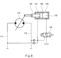
- Patent Document 1 discloses a tilt angle control device 100 for a hydraulic motor 110 as shown in FIG.
- the tilt angle control device 100 switches the tilt angle of the hydraulic motor 110 in two steps by an electric signal.
- the tilt angle control device 100 includes a servo piston 120 that moves in a flow rate increasing direction that increases the tilt angle of the hydraulic motor 110 and a flow rate decreasing direction that decreases the tilt angle.
- a housing 130 forming a first pressure receiving chamber 131 and a second pressure receiving chamber 132.
- the first pressure receiving chamber 131 is for moving the servo piston 120 in the flow rate increasing direction
- the second pressure receiving chamber 132 is for moving the servo piston 120 in the flow rate decreasing direction.
- the cross-sectional area of the second pressure receiving chamber 132 is larger than the cross-sectional area of the first pressure receiving chamber 131.
- a hydraulic pressure (the higher pressure of the pair of supply / discharge passages 111 and 112) flowing into the hydraulic motor 110 is guided.
- the second pressure receiving chamber 132 is connected to the electromagnetic valve 140.
- the solenoid valve 140 communicates the second pressure receiving chamber 132 with the tank when the command current is not supplied. Thereby, the tilt angle of the hydraulic motor 110 is maximized.
- the electromagnetic valve 140 guides the hydraulic pressure flowing into the hydraulic motor 110 to the second pressure receiving chamber 132 when the command current is supplied. As a result, the tilt angle of the hydraulic motor 110 is minimized.
- an object of the present invention is to make it possible to adjust the tilt angle of the hydraulic rotating machine to an arbitrary angle according to an electric signal.
- the present invention provides a servo piston that moves in a flow rate increasing direction that increases a tilt angle of a variable displacement hydraulic rotating machine and a flow rate decreasing direction that decreases the tilt angle, and the servo
- a first housing that forms a pressure receiving chamber with the servo piston, and a second housing hole that is adjacent to the first housing on the side of the servo piston and extends parallel to the axial direction of the servo piston.
- a housing a supply passage formed in a casing of the hydraulic rotary machine, a reference flow path communicating with the first pressure receiving chamber, and the housing hole, the second pressure receiving chamber being A spool that allows the second pressure receiving chamber to communicate with one of the supply path and the tank according to the moving direction when moved from a pressure adjusting position that is cut off from both the supply path and the tank, and a feedback piston disposed in the accommodation hole And a feedback lever that connects the servo piston and the feedback piston, a spring that biases the spool and the feedback lever away from each other, and a pressing force proportional to a command current from the opposite side of the spring.
- a tilt angle control device for a hydraulic rotary machine comprising a solenoid that presses the spool.
- the servo piston moves, the feedback piston also moves, so the urging force of the spool by the spring changes. Then, when the pressing force of the spool by the solenoid and the biasing force of the spool by the spring are balanced, the spool is again positioned at the pressure adjusting position.
- the servo piston moves by the amount of change in the command current to the solenoid (that is, the tilt angle of the hydraulic rotating machine changes). Therefore, the tilt angle of the hydraulic rotary machine can be adjusted to an arbitrary angle according to the electrical signal.
- the tilt angle control device is a sleeve that is disposed in the accommodation hole and through which the spool is inserted, and is connected to the input port connected to the reference flow path and the second pressure receiving chamber.
- a sleeve having an output port may be further provided, and the spool may have a land portion that opens and closes the output port.
- the spool has an enlarged diameter portion at an end portion on the solenoid side
- the solenoid includes a plunger for pressing the spool, a fixed magnetic pole penetrating the plunger, and a movable iron core to which the plunger is fixed.
- a cylindrical portion surrounding the enlarged diameter portion of the spool, and the tilt angle control device is disposed in the receiving hole and is pressed against the cylindrical portion of the solenoid by a spring
- the tilt angle is not affected by the command current near the stroke end due to the adsorption of the movable iron core to the fixed magnetic pole. May change rapidly. This phenomenon occurs even when a current dither is applied to the solenoid (when a command current to the solenoid is vibrated).
- the stroke end of the spool is set using a stopper ring arranged in the accommodation hole, the continuous change of the tilt angle by the command current can be ensured even in the vicinity of the stroke end.
- the tilt angle of the hydraulic rotary machine can be adjusted to an arbitrary angle according to the electric signal.
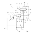
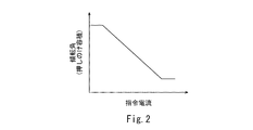
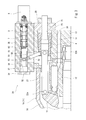
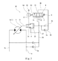
- FIG. 1 is a hydraulic circuit diagram of a tilt angle control device for a hydraulic rotary machine according to an embodiment of the present invention. It is a graph which shows the relationship between the command current to the solenoid in 1st Embodiment, and a tilt angle. It is sectional drawing of the tilt angle control apparatus shown in FIG.
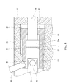
- FIG. 4 is an enlarged view around a servo piston in FIG. 3.
- FIG. 4 is an enlarged view around the spool in FIG. 3.
- FIG. 1 shows a tilt angle control device 2A of a variable displacement hydraulic rotating machine 1 according to an embodiment of the present invention.
- the hydraulic rotary machine 1 is a hydraulic motor 1A.
- the hydraulic rotary machine 1 may be a hydraulic pump.
- the tilt angle control device 2A is a negative type in which a command current to a solenoid 9 described later and a tilt angle (that is, displacement volume) have a negative correlation as shown in FIG.
- the tilt angle control device of the present invention may be a positive type in which the command current and the tilt angle have a positive correlation.
- the hydraulic motor 1A has a structure in which a swash plate 11 and a cylinder block 12 are encased in a first casing 13 and a second casing.
- a pair of supply / discharge passages 1 a and 1 b is formed in the first casing 13 that supports the cylinder block 12.
- the second casing 14 is a cover having a hollow inside.
- a space surrounded by the first casing 13 and the second casing 14 is filled with hydraulic fluid (typically hydraulic fluid) for operating the hydraulic motor 1A, and communicates with the tank.
- the tilt angle control device 2A includes a first housing 3A integrated with the first casing 13 of the hydraulic motor 1A, and a second housing 3B attached to the first housing 3A.
- the first housing 3 ⁇ / b> A may be a separate body from the first casing 13.
- the second housing 3B may be integrated with the first housing 3A.
- the servo piston 4 is slidably held in the first housing 3A.
- the second housing 3B is adjacent to the first housing 3A on the side of the servo piston 4.
- the axial direction of the servo piston 4 is parallel to the axial direction of the hydraulic motor 1A, but the axial direction of the servo piston 4 may be inclined with respect to the axial direction of the hydraulic motor 1A.
- the second casing 14 side left side in FIG. 3) is referred to as the front
- the first casing 13 side (right side in FIG. 3) is referred to as the rear.
- the servo piston 4 is connected to the swash plate 11 of the hydraulic motor 1A by a rod 21 extending in the front-rear direction. More specifically, the front end of the rod 21 is connected to the swash plate 11 by a pin 22a, and the rear end of the rod 21 is connected to the front end of the servo piston 4 by a pin 22b. However, instead of the connection by the pin 22a, the swash plate 11 may be pressed against the front end portion of the rod 21 by a spring. In this case, the rod 21 may be omitted.
- the tilt angle of the hydraulic motor 1A which is the angle of the swash plate 11 with respect to the plane orthogonal to the axial direction of the hydraulic motor 1A, increases, and when the servo piston 4 moves forward, The tilt angle of the pressure motor 1A is reduced. That is, with respect to the servo piston 4, the rear is the flow rate increasing direction and the front is the flow rate decreasing direction.
- the first housing 3 ⁇ / b> A forms a first pressure receiving chamber 31 and a second pressure receiving chamber 32 with the servo piston 4.
- the first pressure receiving chamber 31 is for moving the servo piston 4 in the flow rate increasing direction (backward)
- the second pressure receiving chamber 32 is for moving the servo piston 4 in the flow rate decreasing direction (forward). is there.
- the effective cross-sectional area of the second pressure receiving chamber 32 is larger than the effective cross-sectional area of the first pressure receiving chamber 31. The effective cross-sectional area will be described later.
- the servo piston 4 has a peripheral wall 41 extending in the front-rear direction, a bottom wall 42 that closes the inside of the peripheral wall 41 from the rear, and a flange 43 that protrudes radially outward from the rear end portion of the peripheral wall 41.
- the rear surface of the flange 43 is flush with the rear surface of the bottom wall 42, but they may be displaced in the front-rear direction.
- the rear end portion of the rod 21 described above is inserted into the front end portion of the peripheral wall 41.
- the first pressure receiving chamber 31 described above is a space facing the front surface of the flange 43 and the outer peripheral surface of the peripheral wall 41
- the second pressure receiving chamber 32 is a space facing the rear surface of the flange 43 and the rear surface of the bottom wall 42.
- the effective sectional area of the first pressure receiving chamber 31 described above is an area between the outer peripheral surface of the flange 43 and the outer peripheral surface of the peripheral wall 41 when viewed from the axial direction of the servo piston 4.
- the cross-sectional area is an area between the outer peripheral surface of the flange 43 and the peripheral surface of a shaft portion 23b of the defining member 23 described later when viewed from the axial direction of the servo piston 4.
- the first pressure receiving chamber 31 is connected to the pair of supply / discharge paths 1a and 1b by the reference flow path 36.
- the reference flow path 36 includes one main flow path connected to the first pressure receiving chamber 31 and two branch paths connected to the pair of supply / discharge paths 1a and 1b. Each branch passage is provided with a check valve 3a. That is, the reference flow path 36 communicates the first pressure receiving chamber 31 with the higher pressure supply / discharge path of the pair of supply / discharge paths 1 a, 1 b.
- the higher pressure functions as a supply passage for supplying hydraulic fluid to the hydraulic motor 1A, and the lower pressure as a discharge passage for discharging hydraulic oil from the hydraulic motor 1A.
- the second pressure receiving chamber 32 is connected to an output port 73 of the sleeve 7 which will be described later by a pressure adjusting path 38.
- the pressure adjusting path 38 will be described later.
- Servo piston 4 can move forward until it comes into contact with regulating member 23. That is, the defining member 23 defines the minimum tilt angle.
- the defining member 23 is a rod-shaped member extending in the front-rear direction.
- the defining member 23 includes a head 23 a located in the peripheral wall 41 of the servo piston 4, and a shaft portion 23 b that extends rearward from the head 23 a through the bottom wall 42. Yes.
- a screw thread (not shown) is formed on the rear portion of the shaft portion 23b.
- the defining member 23 is fixed to the first housing 3 ⁇ / b> A via a fixing member 24 having a screw hole and a nut 25.
- the second housing 3 ⁇ / b> B is provided with a receiving hole 33 extending in parallel with the axial direction of the servo piston 4.
- the accommodation hole 33 penetrates the second housing 3B in the front-rear direction.
- the front opening of the receiving hole 33 is closed by a cap 34 attached to the front surface of the second housing 3B, and the rear opening of the receiving hole 33 is closed by a solenoid 9 attached to the rear face of the second housing 3B. ing.
- the feedback piston 54 In the accommodation hole 33, the feedback piston 54, the sleeve 7 and the spool 8 are arranged.
- the feedback piston 54 is located on the front side of the accommodation hole 33, and the sleeve 7 is located on the rear side of the accommodation hole 33.
- the spool 8 is inserted through the sleeve 7.
- a first spring 61 and a spring seat 62 are disposed between the feedback piston 54 and the spool 8.
- the feedback piston 54 is slidably held in the second housing 3B.
- the feedback piston 54 is connected to the servo piston 4 by a feedback lever 51.
- the feedback lever 51 has a length straddling the servo piston 4 and the feedback piston 54 and is supported by a pin 52 so as to be swingable at a substantially central position.
- the pin 52 is fixed to the second housing 3B.
- the feedback lever 51 has one end that engages with the servo piston 4.
- An engagement hole 44 (see FIG. 4) is formed in the front end portion of the peripheral wall 41 of the servo piston 4, and one end of the feedback lever 51 is inserted into the engagement hole 44.
- an engagement pin 53 is provided at the other end of the feedback lever 51.
- the feedback piston 54 is a tubular member, and is provided with a slit 55 extending in a direction orthogonal to the axial direction.
- An engagement pin 53 provided at the other end of the feedback lever 51 is engaged with the slit 55. Therefore, when the servo piston 4 moves forward, the feedback piston 51 moves backward by the clockwise swing of the feedback lever 51 in FIG. 3, and when the servo piston 4 moves backward, the feedback lever 51 in FIG.
- the feedback piston 54 moves forward by the counterclockwise swing.
- a stepped portion 56 is formed on the inner peripheral surface of the feedback piston 54 by expanding the diameter of the rear portion, and the front portion of the first spring 61 is inserted into the stepped portion 56.
- the first spring 61 presses the front end portion of the spool 8 via the spring seat 62.
- the first spring 61 biases the feedback piston 54 and the spool 8 so as to be separated from each other.
- the first spring 61 may directly press the front end portion of the spool 8.
- a ring-shaped protrusion 35 is formed substantially at the center of the accommodation hole 33.
- the sleeve 7 is pressed against the protrusion 35 by a second spring 63 disposed in the accommodation hole 33.
- a tank port 72, an output port 73, and an input port 71 are formed in this order from the front side.
- Each of the tank port 72, the output port 73, and the input port 71 includes a circumferentially continuous groove formed on the outer peripheral surface of the sleeve 7 and a plurality of through holes extending from the groove to the inner peripheral surface of the sleeve 7. Is done.
- the input port 71 is connected to the main flow path of the reference flow path 36 by the input path 37, and the tank port 72 is connected to the tank by the tank path 74.
- the contact between the inner side of the sleeve 7 and the front side of the projection 35 of the accommodation hole 33 may be cut off by the contact of the spring seat 62 with the sleeve 7.
- the tank port 72 is for coping with the disconnection. However, the tank port 72 can be omitted when communication between the inside of the sleeve 7 and the front side of the projection 35 of the accommodation hole 33 is always ensured.
- the output port 73 is connected to the second pressure receiving chamber 32 by the pressure adjusting path 38.
- the pressure regulating path 38 is provided with a throttle 3b.
- the pressure adjusting path 38 is connected to a bypass path 39 that bypasses the throttle 3b.
- the bypass passage 39 is provided with a check valve 3c that allows a flow from the second pressure receiving chamber 32 to the output port 73 but prohibits a flow from the output port 73 to the second pressure receiving chamber 32.
- the spool 8 is normally located at a pressure adjusting position where the second pressure receiving chamber 32 is cut off from both the supply path (the higher pressure of the supply / discharge paths 1a and 1b) and the tank. Then, when the spool 8 moves from the pressure adjusting position, the spool 8 communicates with the one of the supply path and the tank according to the moving direction.
- the spool 8 includes a first small diameter portion 81, a first land portion 82, a second small diameter portion 83, a second land portion 84, a third small diameter portion 85, and an enlarged diameter portion 86. These portions 81 to 86 are arranged in this order from the front side. That is, the enlarged diameter portion 86 is located at the rear end portion (end portion on the solenoid 9 side) of the spool 8.
- the first land portion 82 closes the output port 73 when the spool 8 is located at the pressure adjusting position, and opens the output port 73 when the spool 8 moves from the pressure adjusting position.
- the output port 73 passes through the annular flow path between the first small diameter portion 81 and the inner peripheral surface of the sleeve 7 and the front side portion of the housing hole 33 and the tank It communicates with port 72.
- the output port 73 communicates with the input port 71 through the annular flow path between the second small diameter portion 83 and the inner peripheral surface of the sleeve 7.
- the second land portion 84 serves to close the gap between the second small diameter portion 83 and the inner peripheral surface of the sleeve 7 from the rear.
- the solenoid 9 presses the spool 8 from the opposite side to the first spring 61 with a pressing force proportional to the command current supplied to the solenoid 9.
- the solenoid 9 includes a plunger 93 extending in the front-rear direction for pressing the rear end portion of the spool 8, a fixed magnetic pole 92 penetrating the plunger 93, and a rear end of the plunger 93. Includes a movable iron core 94 that is fixed.
- the solenoid 9 includes a cylindrical portion 91 that is inserted into the accommodation hole 33 and surrounds the enlarged diameter portion 86 of the spool 8.
- a stopper ring 64 is disposed in the accommodation hole 33 in the vicinity of the cylindrical portion 91.
- the stopper ring 64 is pressed against the cylindrical portion 91 by the second spring 63 described above.
- the inner diameter of the stopper ring 64 is smaller than the diameter of the enlarged diameter portion 86 of the spool 8.
- a gap S2 is formed between the enlarged diameter portion 86 of the spool 8 and the stopper ring 64.
- the gap S2 is smaller than the gap S1 between the movable iron core 94 of the solenoid 9 and the fixed magnetic pole 92. For this reason, when the command current is supplied to the solenoid 9 and the movable iron core 94 is advanced toward the fixed magnetic pole 92, the diameter-expanded portion 86 of the spool 8 stops the stopper before the movable iron core 94 contacts the fixed magnetic pole 92. It abuts on the ring 64.
- the servo piston 4 moves by the amount of change in the command current to the solenoid 9 (that is, the tilt angle of the hydraulic motor 1A changes). Therefore, the tilt angle of the hydraulic motor 1A can be adjusted to an arbitrary angle according to the electrical signal.
- the position of the servo piston 4 is fed back by the biasing force of the first spring 61, so that the stroke of the spool 8 is sufficient even if it is short. Therefore, a small solenoid 9 can be used.
- a stopper ring 64 for contacting the enlarged diameter portion 86 of the spool 8 is disposed in the accommodation hole 33.
- the command current is increased in the vicinity of the stroke end due to the adsorption of the movable iron core 94 to the fixed magnetic pole 92. Regardless of this, the tilt angle may change abruptly. This phenomenon occurs even when current dither is applied to the solenoid 9.
- the stroke end of the spool 8 is set using the stopper ring 64 disposed in the accommodation hole 33, the continuous change of the tilt angle by the command current can be secured even in the vicinity of the stroke end. .
- the reference flow path 36 may be a single flow path branched from the discharge path 1d.
- the tilt angle control device 2B of the hydraulic pump 1B can be realized.
- the hydraulic pump 1B has the same structure as the hydraulic motor 1A except that it has a suction path 1c and a discharge path 1d instead of the pair of supply / discharge paths 1a and 1b.
- a pin 52 for swingably supporting the feedback lever 51 is disposed on the opposite side of the servo piston 4 with respect to the feedback piston 54, and the input port 71 and the tank port 72 of the sleeve 7 are connected. If the positions are switched, the positive tilt angle control device 2C can be realized. This modification can also be applied to the tilt angle control device 2B of the hydraulic pump 1B shown in FIG.
- the sleeve 7 may be omitted, and the input port 71, the tank port 72, and the output port 73 may be formed in the second housing 3B.
Landscapes
- Engineering & Computer Science (AREA)
- Mechanical Engineering (AREA)
- General Engineering & Computer Science (AREA)
- Reciprocating Pumps (AREA)
- Control Of Positive-Displacement Pumps (AREA)
Abstract
液圧回転機械の傾転角制御装置は、流量増加方向および流量減少方向に移動するサーボピストンと、サーボピストンとの間に第1受圧室および第2受圧室を形成する第1ハウジングと、サーボピストンの軸方向と平行に延びる収容穴が設けられた第2ハウジングと、液圧回転機械のケーシングに形成された供給路と第1受圧室を連通する基準流路と、収容穴内に配置され、調圧位置から移動したときに第2受圧室を移動方向に応じて供給路とタンクの一方と連通させるスプールと、収容穴内に配置された、フィードバックレバーによりサーボピストンと連結されたフィードバックピストンと、スプールとフィードバックレバーとを互いに離間するように付勢するスプリングと、指令電流と比例する押圧力でスプリングと反対側からスプールを押圧するソレノイドと、を備える。
Description
本発明は、可変容量型の液圧回転機械の傾転角制御装置に関する。
可変容量型の液圧回転機械には、傾転角に応じて吐出流量が変更可能な液圧ポンプと、傾転角に応じて回転速度が変更可能な液圧モータがある。このような液圧回転機械の傾転角は、傾転角制御装置により制御される。
例えば、特許文献1には、図8に示すような液圧モータ110の傾転角制御装置100が開示されている。この傾転角制御装置100は、電気信号により液圧モータ110の傾転角を二段階で切り換えるものである。
具体的に、傾転角制御装置100は、液圧モータ110の傾転角を大きくする流量増加方向および傾転角を小さくする流量減少方向に移動するサーボピストン120と、サーボピストン120との間に第1受圧室131および第2受圧室132を形成するハウジング130を含む。第1受圧室131は、サーボピストン120を流量増加方向に移動させるためのものであり、第2受圧室132は、サーボピストン120を流量減少方向に移動させるためのものである。第2受圧室132の断面積は、第1受圧室131の断面積よりも大きい。
第1受圧室131には、液圧モータ110へ流入する液圧の圧力(一対の給排路111,112のうちの高い方の圧力)が導かれる。第2受圧室132は、電磁弁140と接続されている。電磁弁140は、指令電流が送給されないときは第2受圧室132をタンクと連通する。これにより、液圧モータ110の傾転角が最大とされる。一方、電磁弁140は、指令電流が送給されたときに、液圧モータ110へ流入する液圧の圧力を第2受圧室132へ導く。これにより、液圧モータ110の傾転角が最小とされる。
ところで、液圧回転機械の傾転角については、電気信号に応じて傾転角を任意の角度に調整したいという要望がある。
そこで、本発明は、液圧回転機械の傾転角を電気信号に応じて任意の角度に調整できるようにすることを目的とする。
前記課題を解決するために、本発明は、可変容量型の液圧回転機械の傾転角を大きくする流量増加方向および前記傾転角を小さくする流量減少方向に移動するサーボピストンと、前記サーボピストンを前記流量増加方向に移動させるための第1受圧室および前記サーボピストンを前記流量減少方向に移動させるための第2受圧室であって前記第1受圧室よりも有効断面積の大きな第2受圧室を前記サーボピストンとの間に形成する第1ハウジングと、前記サーボピストンの側方で前記第1ハウジングに隣接する、前記サーボピストンの軸方向と平行に延びる収容穴が設けられた第2ハウジングと、前記液圧回転機械のケーシングに形成された供給路と前記第1受圧室を連通する基準流路と、前記収容穴内に配置され、前記第2受圧室を前記供給路とタンクの双方から遮断する調圧位置から移動したときに前記第2受圧室を移動方向に応じて前記供給路とタンクの一方と連通させるスプールと、前記収容穴内に配置されたフィードバックピストンと、前記サーボピストンと前記フィードバックピストンとを連結するフィードバックレバーと、前記スプールと前記フィードバックレバーとを互いに離間するように付勢するスプリングと、指令電流と比例する押圧力で前記スプリングと反対側から前記スプールを押圧するソレノイドと、を備える、液圧回転機械の傾転角制御装置を提供する。
上記の構成によれば、スプールが調圧位置に位置する状態でソレノイドへの指令電流を変更すると、第2受圧室へ導かれる圧力が変わり、サーボピストンが移動する。サーボピストンが移動すると、フィードバックピストンも移動するため、スプリングによるスプールの付勢力が変わる。そして、ソレノイドによるスプールの押圧力とスプリングによるスプールの付勢力が釣り合うと、スプールが再び調圧位置に位置する。このような原理によって、ソレノイドへの指令電流の変更量分だけ、サーボピストンが移動する(つまり、液圧回転機械の傾転角が変わる)。従って、液圧回転機械の傾転角を電気信号に応じて任意の角度に調整することができる。
例えば、上記の傾転角制御装置は、前記収容穴内に配置された、前記スプールが挿通されるスリーブであって、前記基準流路と接続された入力ポートおよび前記第2受圧室と接続された出力ポートが形成されたスリーブをさらに備え、前記スプールは、前記出力ポートを開閉するランド部を有してもよい。
前記スプールは、前記ソレノイド側の端部に拡径部を有し、前記ソレノイドは、前記スプールを押圧するためのプランジャと、前記プランジャに貫通される固定磁極と、前記プランジャが固定された可動鉄心と、前記スプールの拡径部を囲繞する筒状部と、を含み、上記の傾転角制御装置は、前記収容穴内に配置された、スプリングによって前記ソレノイドの筒状部に押し付けられたストッパーリングをさらに備え、前記ソレノイドに指令電流が供給されて前記可動鉄心が前記固定磁極に向かって前進させられたときに、前記可動鉄心が前記固定磁極に当接する前に前記拡径部が前記ストッパーリングに当接してもよい。
スプールのストロークエンドを設定するためにソレノイドの固定磁極を可動鉄心のストッパーとして使用した場合には、固定磁極への可動鉄心の吸着によって、ストロークエンドの近傍で、指令電流によらずに傾転角が急激に変化することがある。この現象は、ソレノイドに電流ディザを印加した場合(ソレノイドへの指令電流を振動させた場合)でも発生する。これに対し、収容穴内に配置されたストッパーリングを用いてスプールのストロークエンドを設定すれば、ストロークエンドの近傍でも、指令電流による傾転角の連続変化性を確保することができる。
本発明によれば、液圧回転機械の傾転角を電気信号に応じて任意の角度に調整することができる。
図1に、本発明の一実施形態に係る、可変容量型の液圧回転機械1の傾転角制御装置2Aを示す。本実施形態では、液圧回転機械1が液圧モータ1Aである。ただし、液圧回転機械1は、液圧ポンプであってもよい。
本実施形態では、傾転角制御装置2Aが、図2に示すように後述するソレノイド9への指令電流と傾転角(つまり、押しのけ容積)が負の相関を示すネガティブ型である。ただし、本発明の傾転角制御装置は、指令電流と傾転角が正の相関を示すポジティブ型であってもよい。
図1および図3に示すように、液圧モータ1Aは、斜板11とシリンダブロック12が第1ケーシング13および第2ケーシング14で包み込まれた構造を有している。シリンダブロック12を支持する第1ケーシング13には、一対の給排路1a,1bが形成されている。第2ケーシング14は、内部が空洞のカバーである。第1ケーシング13および第2ケーシング14で囲まれる空間は、液圧モータ1Aの作動用の作動液(典型的には、作動油)で満たされており、タンクと連通している。
傾転角制御装置2Aは、液圧モータ1Aの第1ケーシング13と一体となった第1ハウジング3Aと、第1ハウジング3Aに取り付けられた第2ハウジング3Bを含む。ただし、第1ハウジング3Aは、第1ケーシング13と別体となっていてもよい。この場合、第2ハウジング3Bは、第1ハウジング3Aと一体となっていてもよい。
第1ハウジング3Aには、サーボピストン4が摺動可能に保持されている。第2ハウジング3Bは、サーボピストン4の側方で第1ハウジング3Aに隣接している。本実施形態では、サーボピストン4の軸方向が液圧モータ1Aの軸方向と平行であるが、サーボピストン4の軸方向は液圧モータ1Aの軸方向に対して傾斜していてもよい。以下、説明の便宜上、液圧モータ1Aの軸方向のうち第2ケーシング14側(図3の左方)を前方、第1ケーシング13側(図3の右方)を後方という。
サーボピストン4は、前後方向に延びるロッド21により液圧モータ1Aの斜板11と連結されている。より詳しくは、ロッド21の前端部がピン22aにより斜板11と結合されており、ロッド21の後端部がピン22bによりサーボピストン4の前端部と結合されている。ただし、ピン22aによる結合に代えて、スプリングによって斜板11をロッド21の前端部に押圧してもよい。この場合、ロッド21が省略されてもよい。
サーボピストン4が後方に移動すると、液圧モータ1Aの軸方向と直交する面に対する斜板11の角度である液圧モータ1Aの傾転角が大きくなり、サーボピストン4が前方に移動すると、液圧モータ1Aの傾転角が小さくなる。つまり、サーボピストン4に関しては、後方が流量増加方向であり、前方が流量減少方向である。
図4に示すように、第1ハウジング3Aは、サーボピストン4との間に第1受圧室31および第2受圧室32を形成する。第1受圧室31は、サーボピストン4を流量増加方向(後方)に移動させるためのものであり、第2受圧室32は、サーボピストン4を流量減少方向(前方)に移動するためのものである。第2受圧室32の有効断面積は、第1受圧室31の有効断面積よりも大きい。有効断面積については、後述する。
サーボピストン4は、前後方向に延びる周壁41と、周壁41の内側を後方から閉塞する底壁42と、周壁41の後端部から径方向外向きに突出するフランジ43を有する。本実施形態では、フランジ43の後面が底壁42の後面と面一であるが、それらは前後方向にずれていてもよい。上述したロッド21の後端部は、周壁41の前端部内に挿入されている。上述した第1受圧室31は、フランジ43の前面および周壁41の外周面に面する空間であり、第2受圧室32は、フランジ43の後面および底壁42の後面に面する空間である。
上述した第1受圧室31の有効断面積は、サーボピストン4の軸方向から見たときの、フランジ43の外周面と周壁41の外周面の間の面積であり、第2受圧室32の有効断面積は、サーボピストン4の軸方向から見たときの、フランジ43の外周面と後述する規定部材23の軸部23bの周面との間の面積である。
本実施形態では、液圧回転機械1が液圧モータ1Aであるため、第1受圧室31が基準流路36により一対の給排路1a,1bと接続されている。基準流路36は、第1受圧室31に接続された1本の主流路と、一対の給排路1a,1bに接続された2本の分岐路を含む。各分岐路には、逆止弁3aが設けられている。つまり、基準流路36は、一対の給排路1a,1bのうち圧力が高い方の給排路を第1受圧室31と連通する。給排路1a,1bのうち、圧力が高い方が、液圧モータ1Aへ作動液を供給する供給路として機能し、圧力が低い方が、液圧モータ1Aから作動油を排出する排出路として機能する。一方、第2受圧室32は、調圧路38により後述するスリーブ7の出力ポート73と接続されている。調圧路38については、後述する。
サーボピストン4は、規定部材23に当接するまで前進可能である。つまり、規定部材23は、最小傾転角を規定する。規定部材23は、前後方向に延びる棒状部材である。
より詳しくは、図4に示すように、規定部材23は、サーボピストン4の周壁41内に位置するヘッド23aと、ヘッド23aから底壁42を貫通して後方へ延びる軸部23bを有している。軸部23bの後側部分にはネジ山(図示せず)が形成されている。規定部材23は、ネジ穴を有する固定部材24およびナット25を介して第1ハウジング3Aに固定されている。
図3に示すように、第2ハウジング3Bには、サーボピストン4の軸方向と平行に延びる収容穴33が設けられている。本実施形態では、収容穴33が第2ハウジング3Bを前後方向に貫通している。収容穴33の前側開口は、第2ハウジング3Bの前面に取り付けられたキャップ34によって閉塞されており、収容穴33の後側開口は、第2ハウジング3Bの後面に取り付けられたソレノイド9によって閉塞されている。
収容穴33内には、フィードバックピストン54、スリーブ7およびスプール8が配置されている。フィードバックピストン54は、収容穴33の前側に位置しており、スリーブ7は、収容穴33の後側に位置している。スプール8は、スリーブ7に挿通されている。フィードバックピストン54とスプール8の間には、第1スプリング61およびスプリング座62が配置されている。
フィードバックピストン54は、第2ハウジング3Bに摺動可能に保持されている。また、フィードバックピストン54は、フィードバックレバー51によってサーボピストン4と連結されている。フィードバックレバー51は、サーボピストン4とフィードバックピストン54とに跨る長さを有しており、略中央でピン52によって揺動可能に支持されている。ピン52は、第2ハウジング3Bに固定されている。
より詳しくは、フィードバックレバー51は、サーボピストン4に係合する一端を有している。サーボピストン4の周壁41の前端部には、係合穴44(図4参照)が形成されており、この係合穴44にフィードバックレバー51の一端が挿入されている。一方、フィードバックレバー51の他端には、係合ピン53が設けられている。
フィードバックピストン54は、管状の部材であり、軸方向と直交する方向に延びるスリット55が設けられている。このスリット55に、フィードバックレバー51の他端に設けられた係合ピン53が係合している。このため、サーボピストン4が前方に移動すると、フィードバックレバー51の図3における時計回りの揺動によってフィードバックピストン54が後方に移動し、サーボピストン4が後方に移動すると、フィードバックレバー51の図3における反時計回りの揺動によってフィードバックピストン54が前方に移動する。
フィードバックピストン54の内周面には、後側部分に拡径によって段差部56が形成されており、この段差部56内に第1スプリング61の前側部分が挿入されている。第1スプリング61は、スプリング座62を介してスプール8の前端部を押圧する。換言すれば、第1スプリング61は、フィードバックピストン54とスプール8とを互いに離間するように付勢する。ただし、スプール8の形状によっては、第1スプリング61がスプール8の前端部を直接的に押圧してもよい。
図5に示すように、収容穴33の略中央には、リング状の突起35が形成されている。スリーブ7は、収容穴33内に配置された第2スプリング63によって突起35に押し付けられている。
スリーブ7には、前側から順に、タンクポート72、出力ポート73および入力ポート71が形成されている。タンクポート72、出力ポート73および入力ポート71のそれぞれは、スリーブ7の外周面に形成された周方向に連続する溝と、前記溝からスリーブ7の内周面に至る複数の貫通穴とで構成される。
図1に示すように、入力ポート71は、入力路37により基準流路36の主流路と接続されており、タンクポート72は、タンク路74によりタンクと接続されている。本実施形態では、スプリング座62のスリーブ7への当接によって、スリーブ7の内側と収容穴33の突起35よりも前側部分との連通が切断されることがある。タンクポート72は、その切断に対処するためのものである。ただし、スリーブ7の内側と収容穴33の突起35よりも前側部分との連通が常に確保される場合は、タンクポート72は省略可能である。出力ポート73は、上述したように、調圧路38により第2受圧室32と接続されている。
調圧路38には、絞り3bが設けられている。また、調圧路38には、絞り3bをバイパスするバイパス路39が接続されている。バイパス路39には、第2受圧室32から出力ポート73への流れは許容する一方、出力ポート73から第2受圧室32の流れは禁止する逆止弁3cが設けられている。
スプール8は、通常は、第2受圧室32を上述した供給路(給排路1a,1bのうちの圧力の高い方)とタンクの双方から遮断する調圧位置に位置する。そして、スプール8は、調圧位置から移動したときに、第2受圧室32を移動方向に応じて供給路とタンクの一方と連通させる。具体的に、スプール8は、図5に示すように、第1小径部81、第1ランド部82、第2小径部83、第2ランド部84、第3小径部85および拡径部86を有し、これらの部81~86は、前側からこの順に並んでいる。つまり、拡径部86は、スプール8の後端部(ソレノイド9側の端部)に位置する。
第1ランド部82は、スプール8が調圧位置に位置するときに出力ポート73を閉じ、スプール8が調圧位置から移動したときに出力ポート73を開く。出力ポート73は、スプール8が調圧位置から後方に移動したときに、第1小径部81とスリーブ7の内周面の間の環状流路を通じて収容穴33の突起35よりも前側部分およびタンクポート72と連通する。逆に、スプール8が調圧位置から前方に移動したときに、出力ポート73は、第2小径部83とスリーブ7の内周面の間の環状流路を通じて入力ポート71と連通する。第2ランド部84は、第2小径部83とスリーブ7の内周面の間の隙間を後方から閉塞する役割を果たす。
ソレノイド9は、当該ソレノイド9に送給される指令電流と比例する押圧力で第1スプリング61と反対側からスプール8を押圧する。具体的に、ソレノイド9は、図5に示すように、スプール8の後端部を押圧するための前後方向に延びるプランジャ93と、プランジャ93に貫通された固定磁極92と、プランジャ93の後端が固定された可動鉄心94を含む。さらに、ソレノイド9は、収容穴33内に挿入されて、スプール8の拡径部86を囲繞する筒状部91を含む。
一方、収容穴33内には、筒状部91の近傍にストッパーリング64が配置されている。ストッパーリング64は、上述した第2スプリング63によって筒状部91に押し付けられている。ストッパーリング64の内径は、スプール8の拡径部86の直径よりも小さい。
スプール8が調圧位置に位置するとき、スプール8の拡径部86とストッパーリング64の間には隙間S2が形成されている。この隙間S2は、ソレノイド9の可動鉄心94と固定磁極92の間の隙間S1よりも小さい。このため、ソレノイド9に指令電流が供給されて可動鉄心94が固定磁極92に向かって前進させられたときに、可動鉄心94が固定磁極92に当接する前にスプール8の拡径部86がストッパーリング64に当接する。
ソレノイド9には、電流ディザが印加される。つまり、ソレノイド9への指令電流が振動させられる。このような電流ディザによって、スプール8が安定的に移動する。ただし、ソレノイド9に電流ディザが印加されなくてもよい。
以上説明した構成の傾転角制御装置2Aでは、スプール8が調圧位置に位置する状態でソレノイド9への指令電流を変更すると、第2受圧室32へ導かれる圧力が変わり、サーボピストン4が移動する。サーボピストン4が移動すると、フィードバックピストン54も移動するため、第1スプリング61によるスプール8の付勢力が変わる。そして、ソレノイド9によるスプール8の押圧力と第1スプリング61によるスプール8の付勢力が釣り合うと、スプール8が再び調圧位置に位置する。このような原理によって、ソレノイド9への指令電流の変更量分だけ、サーボピストン4が移動する(つまり、液圧モータ1Aの傾転角が変わる)。従って、液圧モータ1Aの傾転角を電気信号に応じて任意の角度に調整することができる。
しかも、本実施形態では、サーボピストン4の位置を第1スプリング61の付勢力でフィードバックしているので、スプール8のストロークは短くても十分である。従って、小型のソレノイド9を使用することができる。
さらに、本実施形態では、収容穴33内にスプール8の拡径部86との当接用のストッパーリング64が配置されている。スプール8のストロークエンドを設定するためにソレノイド9の固定磁極92を可動鉄心94のストッパーとして使用した場合には、固定磁極92への可動鉄心94の吸着によって、ストロークエンドの近傍で、指令電流によらずに傾転角が急激に変化することがある。この現象は、ソレノイド9に電流ディザを印加した場合でも発生する。これに対し、収容穴33内に配置されたストッパーリング64を用いてスプール8のストロークエンドを設定すれば、ストロークエンドの近傍でも、指令電流による傾転角の連続変化性を確保することができる。
(その他の実施形態)
本発明は上述した実施形態に限定されるものではなく、本発明の要旨を逸脱しない範囲で種々の変形が可能である。
本発明は上述した実施形態に限定されるものではなく、本発明の要旨を逸脱しない範囲で種々の変形が可能である。
例えば、図6に示すように、液圧回転機械1が液圧ポンプ1Bである場合は、基準流路36が吐出路1dから分岐する1本の流路であってもよい。これにより、液圧ポンプ1Bの傾転角制御装置2Bを実現できる。液圧ポンプ1Bは、一対の給排路1a,1bの代わりに、吸入路1cおよび吐出路1dを有する点以外は、液圧モータ1Aと同様の構造を有している。
また、図7に示すように、フィードバックレバー51を揺動可能に支持するピン52をフィードバックピストン54に対してサーボピストン4と反対側に配置するとともに、スリーブ7の入力ポート71とタンクポート72の位置を入れ替えれば、ポジティブ型の傾転角制御装置2Cを実現できる。この変形は、図6に示す液圧ポンプ1Bの傾転角制御装置2Bにも適用可能である。
また、スリーブ7が省略されて、入力ポート71、タンクポート72および出力ポート73が第2ハウジング3Bに形成されてもよい。
1 液圧回転機械
1a,1b 給排路(供給路)
1c 吐出路(供給路)
13,14 ケーシング
2A~2C 傾転角制御装置
3A 第1ハウジング
3B 第2ハウジング
31 第1受圧室
32 第2受圧室
34 収容穴
35 基準流路
4 サーボピストン
51 フィードバックレバー
54 フィードバックピストン
61 第1スピリング
63 第2スプリング
64 ストッパーリング
7 スリーブ
71 入力ポート
72 タンクポート
73 出力ポート
8 スプール
82,84 ランド部
86 拡径部
9 ソレノイド
91 筒状部
92 固定磁極
93 プランジャ
94 可動鉄心
1a,1b 給排路(供給路)
1c 吐出路(供給路)
13,14 ケーシング
2A~2C 傾転角制御装置
3A 第1ハウジング
3B 第2ハウジング
31 第1受圧室
32 第2受圧室
34 収容穴
35 基準流路
4 サーボピストン
51 フィードバックレバー
54 フィードバックピストン
61 第1スピリング
63 第2スプリング
64 ストッパーリング
7 スリーブ
71 入力ポート
72 タンクポート
73 出力ポート
8 スプール
82,84 ランド部
86 拡径部
9 ソレノイド
91 筒状部
92 固定磁極
93 プランジャ
94 可動鉄心
Claims (3)
- 可変容量型の液圧回転機械の傾転角を大きくする流量増加方向および前記傾転角を小さくする流量減少方向に移動するサーボピストンと、
前記サーボピストンを前記流量増加方向に移動させるための第1受圧室および前記サーボピストンを前記流量減少方向に移動させるための第2受圧室であって前記第1受圧室よりも有効断面積の大きな第2受圧室を前記サーボピストンとの間に形成する第1ハウジングと、
前記サーボピストンの側方で前記第1ハウジングに隣接する、前記サーボピストンの軸方向と平行に延びる収容穴が設けられた第2ハウジングと、
前記液圧回転機械のケーシングに形成された供給路と前記第1受圧室を連通する基準流路と、
前記収容穴内に配置され、前記第2受圧室を前記供給路とタンクの双方から遮断する調圧位置から移動したときに前記第2受圧室を移動方向に応じて前記供給路とタンクの一方と連通させるスプールと、
前記収容穴内に配置されたフィードバックピストンと、
前記サーボピストンと前記フィードバックピストンとを連結するフィードバックレバーと、
前記スプールと前記フィードバックレバーとを互いに離間するように付勢するスプリングと、
指令電流と比例する押圧力で前記スプリングと反対側から前記スプールを押圧するソレノイドと、
を備える、液圧回転機械の傾転角制御装置。 - 前記収容穴内に配置された、前記スプールが挿通されるスリーブであって、前記基準流路と接続された入力ポートおよび前記第2受圧室と接続された出力ポートが形成されたスリーブをさらに備え、
前記スプールは、前記出力ポートを開閉するランド部を有する、請求項1に記載の液圧回転機械の傾転角制御装置。 - 前記スプールは、前記ソレノイド側の端部に拡径部を有し、
前記ソレノイドは、前記スプールを押圧するためのプランジャと、前記プランジャに貫通される固定磁極と、前記プランジャが固定された可動鉄心と、前記スプールの拡径部を囲繞する筒状部と、を含み、
前記収容穴内に配置された、スプリングによって前記ソレノイドの筒状部に押し付けられたストッパーリングをさらに備え、
前記ソレノイドに指令電流が供給されて前記可動鉄心が前記固定磁極に向かって前進させられたときに、前記可動鉄心が前記固定磁極に当接する前に前記拡径部が前記ストッパーリングに当接する、請求項1または2に記載の液圧回転機械の傾転角制御装置。
Applications Claiming Priority (2)
| Application Number | Priority Date | Filing Date | Title |
|---|---|---|---|
| JP2016094712A JP6749137B2 (ja) | 2016-05-10 | 2016-05-10 | 液圧回転機械の傾転角制御装置 |
| JP2016-094712 | 2016-05-10 |
Publications (1)
| Publication Number | Publication Date |
|---|---|
| WO2017195589A1 true WO2017195589A1 (ja) | 2017-11-16 |
Family
ID=60266591
Family Applications (1)
| Application Number | Title | Priority Date | Filing Date |
|---|---|---|---|
| PCT/JP2017/016337 Ceased WO2017195589A1 (ja) | 2016-05-10 | 2017-04-25 | 液圧回転機械の傾転角制御装置 |
Country Status (2)
| Country | Link |
|---|---|
| JP (1) | JP6749137B2 (ja) |
| WO (1) | WO2017195589A1 (ja) |
Families Citing this family (2)
| Publication number | Priority date | Publication date | Assignee | Title |
|---|---|---|---|---|
| JP7051475B2 (ja) * | 2018-02-09 | 2022-04-11 | ナブテスコ株式会社 | 油圧ポンプ |
| US12331740B2 (en) * | 2022-12-05 | 2025-06-17 | Hamilton Sundstrand Corporation | Variable displacement pumps |
Citations (4)
| Publication number | Priority date | Publication date | Assignee | Title |
|---|---|---|---|---|
| JPS59140975A (ja) * | 1983-11-29 | 1984-08-13 | Kayaba Ind Co Ltd | パイロツト切換弁のダンピング装置 |
| JPS643089U (ja) * | 1987-06-23 | 1989-01-10 | ||
| JPH0482384U (ja) * | 1990-11-29 | 1992-07-17 | ||
| WO2006129431A1 (ja) * | 2005-05-30 | 2006-12-07 | Hitachi Construction Machinery Co., Ltd. | 可変容量型斜板式液圧回転機 |
-
2016
- 2016-05-10 JP JP2016094712A patent/JP6749137B2/ja active Active
-
2017
- 2017-04-25 WO PCT/JP2017/016337 patent/WO2017195589A1/ja not_active Ceased
Patent Citations (4)
| Publication number | Priority date | Publication date | Assignee | Title |
|---|---|---|---|---|
| JPS59140975A (ja) * | 1983-11-29 | 1984-08-13 | Kayaba Ind Co Ltd | パイロツト切換弁のダンピング装置 |
| JPS643089U (ja) * | 1987-06-23 | 1989-01-10 | ||
| JPH0482384U (ja) * | 1990-11-29 | 1992-07-17 | ||
| WO2006129431A1 (ja) * | 2005-05-30 | 2006-12-07 | Hitachi Construction Machinery Co., Ltd. | 可変容量型斜板式液圧回転機 |
Also Published As
| Publication number | Publication date |
|---|---|
| JP2017203399A (ja) | 2017-11-16 |
| JP6749137B2 (ja) | 2020-09-02 |
Similar Documents
| Publication | Publication Date | Title |
|---|---|---|
| JP6613135B2 (ja) | 斜板ポンプの容量調整装置 | |
| US8100142B2 (en) | Bleed-type electromagnetic valve | |
| KR101702250B1 (ko) | 펌프 용적 제어 장치 | |
| JP2012154389A (ja) | スプールバルブ | |
| KR20150074164A (ko) | 완충 밸브 | |
| WO2019216193A1 (ja) | 電磁流量制御弁 | |
| JP6749137B2 (ja) | 液圧回転機械の傾転角制御装置 | |
| CN109790931B (zh) | 滑阀和阀系统 | |
| JP3820273B2 (ja) | 油圧ポンプの流量制御弁 | |
| JP7033463B2 (ja) | スプール弁装置 | |
| JP4998315B2 (ja) | 電磁弁 | |
| JP5355170B2 (ja) | パイロットバルブ | |
| JP6284469B2 (ja) | 油圧回路 | |
| JP2011163433A (ja) | 電磁比例絞り弁 | |
| JP4998366B2 (ja) | 電磁弁 | |
| JP2008534887A (ja) | 方向制御弁および方向制御弁を備えた制御装置 | |
| JP3758109B2 (ja) | 減圧弁 | |
| JP2019196777A (ja) | スプール弁 | |
| EP3594541A1 (en) | Electromagnetic pressure reduction valve and fluid pressure control device provided with electromagnetic pressure reduction valve | |
| CN220268070U (zh) | 集成式压力补偿阀 | |
| JP2012067890A (ja) | 減圧弁装置 | |
| JP2003227459A (ja) | 斜板形アキシャルピストンポンプの制御装置 | |
| KR101925516B1 (ko) | 차량용 보조제동장치의 유압밸브 | |
| JP4871774B2 (ja) | リリーフ弁 | |
| JP2001323903A (ja) | 油圧シリンダの流量制御装置 |
Legal Events
| Date | Code | Title | Description |
|---|---|---|---|
| NENP | Non-entry into the national phase |
Ref country code: DE |
|
| 121 | Ep: the epo has been informed by wipo that ep was designated in this application |
Ref document number: 17795950 Country of ref document: EP Kind code of ref document: A1 |
|
| 122 | Ep: pct application non-entry in european phase |
Ref document number: 17795950 Country of ref document: EP Kind code of ref document: A1 |