WO2017191790A1 - Rare-earth permanent magnet, and method for manufacturing same - Google Patents
Rare-earth permanent magnet, and method for manufacturing same Download PDFInfo
- Publication number
- WO2017191790A1 WO2017191790A1 PCT/JP2017/016506 JP2017016506W WO2017191790A1 WO 2017191790 A1 WO2017191790 A1 WO 2017191790A1 JP 2017016506 W JP2017016506 W JP 2017016506W WO 2017191790 A1 WO2017191790 A1 WO 2017191790A1
- Authority
- WO
- WIPO (PCT)
- Prior art keywords
- rare earth
- permanent magnet
- earth permanent
- group
- alloy
- Prior art date
Links
Images

Classifications
-
- B—PERFORMING OPERATIONS; TRANSPORTING
- B22—CASTING; POWDER METALLURGY
- B22F—WORKING METALLIC POWDER; MANUFACTURE OF ARTICLES FROM METALLIC POWDER; MAKING METALLIC POWDER; APPARATUS OR DEVICES SPECIALLY ADAPTED FOR METALLIC POWDER
- B22F3/00—Manufacture of workpieces or articles from metallic powder characterised by the manner of compacting or sintering; Apparatus specially adapted therefor ; Presses and furnaces
- B22F3/24—After-treatment of workpieces or articles
-
- B—PERFORMING OPERATIONS; TRANSPORTING
- B22—CASTING; POWDER METALLURGY
- B22F—WORKING METALLIC POWDER; MANUFACTURE OF ARTICLES FROM METALLIC POWDER; MAKING METALLIC POWDER; APPARATUS OR DEVICES SPECIALLY ADAPTED FOR METALLIC POWDER
- B22F9/00—Making metallic powder or suspensions thereof
- B22F9/02—Making metallic powder or suspensions thereof using physical processes
- B22F9/04—Making metallic powder or suspensions thereof using physical processes starting from solid material, e.g. by crushing, grinding or milling
-
- C—CHEMISTRY; METALLURGY
- C22—METALLURGY; FERROUS OR NON-FERROUS ALLOYS; TREATMENT OF ALLOYS OR NON-FERROUS METALS
- C22C—ALLOYS
- C22C38/00—Ferrous alloys, e.g. steel alloys
-
- H—ELECTRICITY
- H01—ELECTRIC ELEMENTS
- H01F—MAGNETS; INDUCTANCES; TRANSFORMERS; SELECTION OF MATERIALS FOR THEIR MAGNETIC PROPERTIES
- H01F1/00—Magnets or magnetic bodies characterised by the magnetic materials therefor; Selection of materials for their magnetic properties
- H01F1/01—Magnets or magnetic bodies characterised by the magnetic materials therefor; Selection of materials for their magnetic properties of inorganic materials
- H01F1/03—Magnets or magnetic bodies characterised by the magnetic materials therefor; Selection of materials for their magnetic properties of inorganic materials characterised by their coercivity
- H01F1/032—Magnets or magnetic bodies characterised by the magnetic materials therefor; Selection of materials for their magnetic properties of inorganic materials characterised by their coercivity of hard-magnetic materials
- H01F1/04—Magnets or magnetic bodies characterised by the magnetic materials therefor; Selection of materials for their magnetic properties of inorganic materials characterised by their coercivity of hard-magnetic materials metals or alloys
- H01F1/047—Alloys characterised by their composition
- H01F1/053—Alloys characterised by their composition containing rare earth metals
- H01F1/055—Alloys characterised by their composition containing rare earth metals and magnetic transition metals, e.g. SmCo5
- H01F1/057—Alloys characterised by their composition containing rare earth metals and magnetic transition metals, e.g. SmCo5 and IIIa elements, e.g. Nd2Fe14B
-
- H—ELECTRICITY
- H01—ELECTRIC ELEMENTS
- H01F—MAGNETS; INDUCTANCES; TRANSFORMERS; SELECTION OF MATERIALS FOR THEIR MAGNETIC PROPERTIES
- H01F41/00—Apparatus or processes specially adapted for manufacturing or assembling magnets, inductances or transformers; Apparatus or processes specially adapted for manufacturing materials characterised by their magnetic properties
- H01F41/02—Apparatus or processes specially adapted for manufacturing or assembling magnets, inductances or transformers; Apparatus or processes specially adapted for manufacturing materials characterised by their magnetic properties for manufacturing cores, coils, or magnets
-
- C—CHEMISTRY; METALLURGY
- C21—METALLURGY OF IRON
- C21D—MODIFYING THE PHYSICAL STRUCTURE OF FERROUS METALS; GENERAL DEVICES FOR HEAT TREATMENT OF FERROUS OR NON-FERROUS METALS OR ALLOYS; MAKING METAL MALLEABLE, e.g. BY DECARBURISATION OR TEMPERING
- C21D6/00—Heat treatment of ferrous alloys
Definitions
- the present invention relates to a rare earth permanent magnet often used in motors, actuators, and the like, and a method for manufacturing the same.
- rare earth magnets are widely used for home appliances, information equipment, industrial applications, etc. due to the high properties of magnets, and in particular, recently, hybrid vehicles (HEV), plug-in hybrid vehicles (PHV), electric vehicles (EV). ) Drive motors, electrical drive motors, actuators, etc.
- HEV hybrid vehicles
- PHY plug-in hybrid vehicles
- EV electric vehicles
- the so-called Nd 2 Fe 14 B structure (which includes additives other than Nd, Fe and B, and Nd is a composition of other rare earth elements, for example, Nd is Pr, Tb, Dy, etc.
- Magnets having various compositions such as compositions substituted with rare earth elements of the present invention (hereinafter referred to as 2-14-1 phases) (hereinafter referred to as RFeB magnets, rare earth elements being mainly Nd).
- the NdFeB magnet has been expanded as a favorite material for rare earth magnets for more than 30 years since its discovery in 1982.
- the NdFeB magnet is a magnet mainly composed of Nd, which has a medium amount of resources among rare earth elements, and Fe, which is the most common transition metal, and these elements have parallel magnetic moments of Nd and Fe. Therefore, it is a combination that has the highest saturation magnetization Ms, and is a combination of magnets that are excellent in terms of economy and resources, and also excellent in magnetic properties.
- the NdFeB magnet is a very good magnet, but unfortunately has some problems with magnetic properties.
- the biggest problem is that the coercive force Hc is low, which is particularly fatal when used at a high temperature exceeding 100 ° C. such as in-vehicle use.
- the Curie temperature Tc is about 310 ° C., and the temperature change of the magnetic characteristics is also a factor that limits the use range in high temperature applications.
- a high Fe ratio is a merit from an economic point of view, but a point of being easily rusted is a demerit.
- the coercive force Hc can be increased by replacing Nd with a heavy rare earth element (for example, Tb, Dy, etc.), which is applied to a mass-produced magnet.
- a heavy rare earth element for example, Tb, Dy, etc.
- Tb Curie temperature
- Dy Dy
- various surface coatings including plating are used depending on the purpose of the magnet, which is an important technique in corrosion resistance.
- Replacing Nd with heavy rare earth elements to improve the coercive force Hc is very effective, but causes two major problems.
- the first problem is that since the magnetic moment of heavy rare earth elements is antiparallel to the magnetic moment of Fe, the saturation magnetization Ms decreases in proportion to the amount of substitution of heavy rare earth elements, that is, the use of heavy rare earth elements.
- the problem is that the coercive force Hc and the saturation magnetization Ms, which are the two main elements of the magnetic characteristics, increase the coercive force Hc but reduce the saturation magnetization Ms.
- the second problem is that heavy rare earth elements are rare resources, so if the demand for raw materials is high and the demand exceeds the amount in the market, the price will rise rapidly. It is. Furthermore, heavy rare earth elements have high geopolitical risks, as evidenced by the turmoil of rare earth resources generated in the past and the confusion of resource shortages, as resources are unevenly distributed in specific countries.
- the coercive force Hc and the saturation magnetization Ms are compatible with each other by the addition of Al, Cu, Ga, etc., and the development of a rare earth magnet manufacturing process called a two-alloy method or a grain boundary diffusion method.
- the disadvantages of using heavy rare earth elements have been improved to some extent.
- the grain boundary diffusion method is effective in reducing heavy rare earth elements such as Tb and Dy.
- the present invention has been made in view of the above circumstances, and in an RFeB magnet having a 2-14-1 phase, the content of heavy rare earth elements is reduced as much as possible, and light rare earth elements containing Y as the rare earth elements are mainly used. It is an object of the present invention to provide a rare earth permanent magnet having a practically sufficient coercive force Hc and saturation magnetization Ms, and high temperature characteristics, and a method for producing the same.
- the present inventor as a rare earth element in a rare earth permanent magnet that contains one or more selected from rare earth elements including Y, Fe, and B, and may contain inevitable impurities
- the composition excluding inevitable impurities is represented by the following composition formula (1).
- R is at least one selected from rare earth elements including Y, and at least one light rare earth element selected from the group consisting of Y, La, Ce, Pr, Nd, Pm, Sm, and Eu.
- R is Ce
- AE is one or more alkaline earth metal elements selected from the group consisting of Ca, Sr and Ba
- M is Cu
- Ni , Ti, Mo, Zr, Hf, Ga, Al and Si are one or more elements selected from the group consisting of x, y and z, where 0 ⁇ x ⁇ 0.4 and 10 ⁇ y ⁇ 20, respectively.
- R in the above formula is composed of only one or more light rare earth elements selected from the group consisting of Y, La, Ce, Pr, Nd, Pm, Sm and Eu.
- the present inventors have found that it can be provided and have come to make the present invention.
- the composition excluding the above inevitable impurities is the following composition formula (1) (R 1-x AE x ) y (Fe 1-a M a ) 100-yz B z (1)
- R is at least one selected from rare earth elements including Y, and at least one light rare earth element selected from the group consisting of Y, La, Ce, Pr, Nd, Pm, Sm, and Eu.
- R is Ce
- AE is one or more alkaline earth metal elements selected from the group consisting of Ca, Sr and Ba
- M is Cu
- Ni , Ti, Mo, Zr, Hf, Ga, Al and Si are one or more elements selected from the group consisting of x, y and z, where 0 ⁇ x ⁇ 0.4 and 10 ⁇ y ⁇ 20, respectively.
- 4 is a positive number that satisfies 4 ⁇ z ⁇ 12
- a is a positive number that satisfies 0 or 0 ⁇ a ⁇ 0.1.
- a rare earth permanent magnet characterized by the following.
- the R in the composition formula (1) is composed of only one or more light rare earth elements selected from the group consisting of Y, La, Ce, Pr, Nd, Pm, Sm and Eu.
- the rare earth permanent magnet according to [1] or [2], wherein 50 atomic% or more of R in the composition formula (1) is a Ce atom having an orbital angular momentum of one 4f electron. .
- LR 2 Fe 14 B (LR is one or more light rare earth elements selected from the group consisting of Y, La, Ce, Pr, Nd, Pm, Sm and Eu, part of which is Ca, Sr and (1), which is substituted with one or more alkaline earth metal elements selected from the group consisting of Ba).
- R in the composition formula (1) is composed of Ce or Ce and one or more rare earth elements selected from the group consisting of La, Pr and Nd. 5] The rare earth permanent magnet according to any one of [5].
- [7] x, y and z in the composition formula (1) are positive numbers satisfying 0.01 ⁇ x ⁇ 0.30, 12 ⁇ y ⁇ 18, and 5 ⁇ z ⁇ 10, respectively, and a is 0.
- the rare earth permanent magnet according to any one of [1] to [6] which is a positive number satisfying 0 ⁇ a ⁇ 0.07.
- x, y, and z in the composition formula (1) are positive numbers satisfying 0.05 ⁇ x ⁇ 0.25, 12 ⁇ y ⁇ 16, and 6 ⁇ z ⁇ 10, respectively, and a is 0.
- the rare earth permanent magnet according to any one of [1] to [8], which is an anisotropic sintered magnet having an apparent density of 95% or more of the true density.
- the composition excluding the above inevitable impurities is the following composition formula (1) (R 1-x AE x ) y (Fe 1-a M a ) 100-yz B z (1) (In the formula, R is at least one selected from rare earth elements including Y, and at least one light rare earth element selected from the group consisting of Y, La, Ce, Pr, Nd, Pm, Sm, and Eu.
- R is Ce
- AE is one or more alkaline earth metal elements selected from the group consisting of Ca, Sr and Ba
- M is Cu
- Ni , Ti, Mo, Zr, Hf, Ga, Al and Si are one or more elements selected from the group consisting of x, y and z, where 0 ⁇ x ⁇ 0.4 and 10 ⁇ y ⁇ 20, respectively.
- a step of preparing an alloy fine powder represented by the following by melting and grinding a single metal and / or an alloy composed of two or more metals and boron and / or an alloy composed of a metal and boron; Applying a magnetic field in a uniaxial direction to the alloy fine powder and orienting the alloy fine powder in the magnetic field direction; A process of compressing and molding oriented alloy fines; A method for producing a rare earth sintered magnet, comprising: a step of sintering a compacted compact, and a step of heat treating the sintered body. [11] The method for producing a rare earth sintered magnet according to [10], wherein an anisotropic sintered magnet having an apparent density of 95% or more of the true density is produced.
- the present invention it is possible to provide a rare earth permanent magnet which can reduce the content of heavy rare earth elements as much as possible and achieve both practically sufficient coercive force Hc and saturation magnetization Ms and high temperature characteristics.
- a candidate material for a permanent magnet capable of exhibiting a sufficient coercive force Hc needs to satisfy the following three requirements. ⁇ High saturation magnetization Ms ⁇ High uniaxial crystal magnetic anisotropy Ku ⁇ Practical enough Curie temperature Tc
- the high saturation magnetization Ms and the high Curie temperature Tc are mainly carried by the transition metal, and in particular, one or both of Fe and Co. This is achieved by using.
- high uniaxial magnetocrystalline anisotropy Ku is influenced mainly by rare earth elements, although transition metals also have a corresponding effect depending on the crystal structure.
- the R-TM compound is a material suitable as a permanent magnet material in which the above three requirements are shared by the rare earth element and the transition metal. The reason why the rare earth element bears the high uniaxial crystal magnetic anisotropy Ku is due to the 4f orbital electron characteristic of the rare earth atom.
- the electron arrangement of the rare earth atoms is (4f) n 5s 2 5p 6 5d6s 2 , and the electrons should be buried first from the 4f orbit, but in reality, the 5s, 5p, 5d and 6s orbitals After the electrons are accommodated in the 4f orbit, the electrons are accommodated in the 4f orbit. Therefore, the 4f electrons of the rare earth atoms are located behind the 5s, 5p, 5d, and 6s electrons. Even after the rare earth atoms form a compound or the like, the orbital angular momentum of the 4f electrons is preserved, and the surrounding electric field ( Although influenced by the crystal field, the orbital angular momentum of 4f electrons is well maintained.
- FIG. 1 shows a 4f electron cloud of rare earth atoms described in RL Coehoorn, “Supermagnets-Hard Magnetic Materials”, GJ Long and F. Grandjean (ed.), Kluwer, 1991, Chapter 8 (Non-patent Document 1).
- the 4f electron cloud of rare earth atoms changes from a flat electron cloud of Ce with a small atomic number to an electron cloud of Sm rugby ball shape from the small atomic number to the large side.
- Gd becomes a spherical electron cloud
- Tb to Lu it again becomes a spherical electron cloud from a flat electron cloud through a rugby ball-shaped electron cloud.
- Uniaxial crystal magnetic anisotropy Ku as a permanent magnet material is that an electron cloud distorted from a spherical shape takes the lowest energy due to the influence of the surrounding electric field (crystal field) (towards the C-axis direction).
- Examples where the flat electron cloud faces the C axis are Nd 2 Fe 14 B, Pr 2 Fe 14 B, etc., and examples where the rugby ball-shaped electron cloud faces the C axis include SmCo 5 and Sm 2 Co 17. Sm 2 Fe 17 N 3 , SmTiFe 11 or the like.
- the high uniaxial magnetocrystalline anisotropy Ku of the R-TM compound is superimposed on the magnetocrystalline anisotropy derived from the transition metal sublattice, but the R-TM compound is highly uniaxial magnetocrystalline anisotropic at room temperature or higher.
- the main factor indicating the property Ku is the shape of the electron cloud of 4f electrons of rare earth atoms (orbital angular momentum).
- an R-TM compound composed of atoms having no or missing 4f electrons or atoms having 4f electrons but having a spherical electron cloud is a permanent magnet. It is unsuitable as a material.
- Table 1 shows the magnetic properties of typical R-TM compounds.
- the magnet has a high potential when R is Nd or Sm, and a magnet with R being Nd or Sm has been put to practical use. Some magnets in which R is Pr are put into practical use.
- the Ce atom has one 4f electron, and shows a very flat electron cloud. Accordingly, the Ce 2 Fe 14 B compound can be considered to have a high uniaxial crystal magnetic anisotropy Ku from the shape of the electron cloud.
- the uniaxial crystal magnetic anisotropy Ku of the Ce 2 Fe 14 B compound is Y 2 Fe 14 B It is the same level as the compound. Since yttrium Y originally does not have 4f electrons, the uniaxial crystal magnetic anisotropy Ku of the Y 2 Fe 14 B compound is derived from the Fe sublattice.
- the Curie temperature Tc of the Ce 2 Fe 14 B compound is 427 K (154 ° C.), which is practically a little lower, but can be improved by substituting part of Fe with Co.
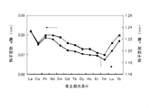
- FIG. 2 is a graph showing changes in the lattice constant of the R 2 Fe 14 B compound.
- Ce 2 lattice constant of a-axis and c-axis of the Fe 14 B compound, from the trend of change is considered to take an intermediate value between the La 2 Fe 14 B compound and Pr 2 Fe 14 B compound, Ce 2
- the lattice constants of the a-axis and c-axis of Fe 14 B deviate from this tendency, and both are depressed.
- Patent Document 1 JP-A-59-46008 (Patent Document 1) and JP-A-59-64733 (Patent Document 2), a magnet having a mixed composition of Nd and Ce, respectively, A magnet with a mixed composition of Tb and Ce is shown.
- the Ce atom originally has one 4f electron, but in the Ce 2 Fe 14 B compound, the 4f electron of the Ce atom is mixed with the conduction electron, and the 4f electron is lost from the Ce atom. ing.
- the loss of 4f electrons in the Ce atom is not limited to the Ce 2 Fe 14 B compound, but is a cerium-transition metal compound (Ce-TM compound) CeCo 5 , Ce 2 Co 17 , Ce 2 Fe 17 , CeTiFe It is a phenomenon commonly seen in 11 etc. In these compounds, a drop in lattice constant similar to that of the Ce 2 Fe 14 B compound in the R 2 Fe 14 B compound described above is observed, and the uniaxial magnetocrystalline anisotropy Ku is also low.
- Ce-TM compound cerium-transition metal compound
- a Ce-TM compound mainly composed of Ce As a permanent magnet material was conducted except for an example in which a CeCo 5 compound having a high crystal magnetic anisotropy of a Co sublattice was put into practical use as a Ce (CoFeCu) 5 magnet.
- a Ce 2 Fe 14 B compound As a candidate material for permanent magnets, a Ce 2 Fe 14 B compound, which is a Ce-TM compound, has not attracted attention.
- a Ce 2 Fe 14 B compound which is a Ce-TM compound of a Ce atom that originally has a potential to give a high uniaxial crystal magnetic anisotropy Ku, recalls 4f electrons to the Ce atom and isolates it, Has recovered its inherent magnetism (magnetic moment and magnetic anisotropy), and this Ce atom isolation can be achieved by replacing part of Ce in the Ce 2 Fe 14 B compound with other elements, specifically , Ca, Sr, and Ba.
- the composition is substituted with one or more alkaline earth metal elements selected from the group consisting of Ca, Sr, and Ba, thereby achieving a structure in which the crystal lattice is expanded.
- Patent Document 9 discloses that an R—Fe—M—B—C—C-based alloy magnet to which Ba, Sr, Ca, or the like is added as M has a reduced boron B content.
- carbon C By adding carbon C, the magnetic temperature characteristics of the grain boundary phase containing carbon C are improved, and further, diffusion of carbon C into the grain boundary phase is promoted by the M addition element, and irreversible demagnetization is reduced.
- carbon C is an essential component
- a Ce— such as a Ce 2 Fe 14 B compound has been conventionally used.
- the TM compound has low magnetic properties, and the specific example of the rare earth element R in this case is only a combination of Nd or Nd and a rare earth element other than Ce, and there is no specific example using Ce.
- the present invention is an RFeB magnet having a so-called Nd 2 Fe 14 B structure phase (2-14-1 phase), and R is a magnet mainly composed of Ce.
- the rare earth permanent magnet of the present invention has a composition containing one or more alkaline earth metal elements selected from the group consisting of Ca, Sr and Ba. It is not certain in what form the alkaline earth metal element of the present invention is contained, but the high magnetic properties of the rare earth permanent magnet of which the main component of the rare earth element of the present invention is Ce.
- a structure in which the crystal lattice is expanded by an alkaline earth metal atom in a part of the Ce site of the 2-14-1 phase of the RFeB magnet mainly composed of Ce, particularly, the Ce site with an alkaline earth metal atom. Is presumed to have a substituted structure.
- the rare earth permanent magnet of the present invention has a Ce 2 Fe 14 B structure phase as a 2-14-1 phase in that the essential magnetic anisotropy of Ce atoms is recovered by such a structure. This is completely different from the RFeB magnet.
- one 4f electron of the Ce atom is isolated, in other words, this electron is called back to the 4f orbit instead of being mixed with the conduction electron. Therefore, it is necessary to exist as localized electrons, by increasing the lattice constant without breaking the basic crystal structure of Ce 2 Fe 14 B, and by widening the space for accommodating Ce atoms in the crystal lattice. Have realized it.
- the rare earth permanent magnet of the present invention contains one or more selected from rare earth elements including Y, Fe, and B, and may contain inevitable impurities.
- Inevitable impurities are elements mixed in, for example, a powder sintering process, and mainly include O (oxygen), C (carbon), N (nitrogen), H (hydrogen), and the like.
- the rare earth permanent magnet of the present invention has a composition excluding inevitable impurities having the following composition formula (1): (R 1-x AE x ) y (Fe 1-a M a ) 100-yz B z (1)
- R is at least one selected from rare earth elements including Y, and at least one light rare earth element selected from the group consisting of Y, La, Ce, Pr, Nd, Pm, Sm, and Eu.
- R is Ce
- AE is one or more alkaline earth metal elements selected from the group consisting of Ca, Sr and Ba
- M is Cu
- Ni , Ti, Mo, Zr, Hf, Ga, Al and Si are one or more elements selected from the group consisting of x, y and z, where 0 ⁇ x ⁇ 0.4 and 10 ⁇ y ⁇ 20, respectively.
- 4 is a positive number that satisfies 4 ⁇ z ⁇ 12
- a is a positive number that satisfies 0 or 0 ⁇ a ⁇ 0.1.
- Nd 2 Fe 14 B structure phase tetragonal Nd 2 Fe 14 B type rare earth intermetallic compound phase
- 2-14-1 phase for example, a crystal phase
- RFeB magnet (2-14-1 phase is the largest.
- the element represented by R contained in the rare earth permanent magnet of the present invention is at least one selected from rare earth elements including Y, and R is composed of Y, La, Ce, Pr, Nd, Pm, Sm and Eu.
- the rare earth permanent magnet of the present invention is LR 2 Fe 14 B (LR is one or more light rare earth elements selected from the group consisting of Y, La, Ce, Pr, Nd, Pm, Sm and Eu, preferably Is partially substituted with one or more alkaline earth metal elements selected from the group consisting of Ca, Sr and Ba.) Phase), and the Curie temperature of this phase is more preferably 500K or more.
- the rare earth element R preferably 60 atom% or more, more preferably 70 atom% or more, still more preferably 95 atom% or more, particularly preferably 100 atom% is Ce.
- the Stevens factor ⁇ J preferably contains 0 or a negative light rare earth element such as La, Pr, Nd, etc.
- the rare earth element R contains Ce, La, More preferably, it comprises one or more rare earth elements selected from the group consisting of Pr and Nd.
- heavy rare earth elements other than light rare earth elements such as Y, La, Ce, Pr, Nd, Pm, Sm and Eu, that is, selected from the group consisting of Gd, Tb, Dy, Ho, Er, Tm, Yb and Lu.
- the content thereof is preferably 20 atomic% or less, preferably 10 atomic% or less, more preferably 5 atomic% or less in the rare earth element represented by R.
- N atoms or C atoms are introduced in the vicinity of R atoms in an interstitial manner, such as R 2 Fe 17 N 3 or RTiFe 11 N. If this method is applied, even in an RFeB magnet, a method of introducing N atoms such as R 2 Fe 14 BN x around the R atoms in an interstitial manner is possible, but such interstitial nitrogen compounds are Decomposes at 1,000 ° C. or lower to become RN x , Fe—Me (Me is an additive metal such as Ti) or the like. Interstitial nitrogen compounds can be mixed with organic resin binders as fine powders, compacted and used as bonded magnets, but when sintered magnets are used, lattice expansion by the method of introducing interstitial types Is not applicable.
- the R atom sites in the crystal lattice are partially substituted with atoms having different atomic radii to stabilize the structure, develop the inherent magnetism of the R atoms, It is considered possible to adjust the interaction with the rare earth atom sublattice other than the RFeB magnet mainly composed of Ce of the present invention.
- the content ratio of the alkaline earth metal element AE (x in the composition formula (1)) can be up to 0.4 with respect to the rare earth element R.
- the content x exceeds 0.4, the structure of the 2-14-1 phase becomes unstable, and the Ce amount decreases, resulting in a significant decrease in uniaxial crystal magnetic anisotropy Ku.
- the content ratio x is less than 0.01, lattice expansion is insufficient, 4f electrons of Ce atoms are not sufficiently recovered, and sufficient uniaxial crystal magnetic anisotropy Ku may not be obtained.
- the content ratio x of the alkaline earth metal element AE is that the recovery of the magnetic anisotropy of the Ce atom and the loss of the magnetic anisotropy caused by the electron orbit of the Ce atom in the structure of the 2-14-1 phase.
- the composition of the rare earth permanent magnet of the present invention is such that at least a part of Ce atoms is 4f of Ce atoms in both cases where R is only Ce and R contains Ce and a rare earth element other than Ce. It is necessary that one electron is recovered in the orbit, one 4f electron of Ce atom is isolated, and the 2-14-1 phase has a uniaxial magnetocrystalline anisotropy Ku.
- 50 atom% or more, particularly 60 atom% or more, particularly 70 atom% or more in the rare earth element R is preferably a Ce atom having an orbital angular momentum of one 4f electron.
- the Fe sublattice in the Ce 2 Fe 14 B compound does not change the value of the uniaxial crystal magnetic anisotropy Ku even when the Ce site is expanded.
- the ratio of the alloy of the corresponding composition to the anisotropic magnetic field Ha is preferably 1.5 times or more, particularly preferably 2 times or more, and particularly preferably 2.5 times or more.
- the rare earth permanent magnet of the present invention may contain an element that substitutes Fe as a main component.
- the substitution element M is an additive element used in an RFeB magnet such as an NdFeB magnet, and can be applied to the rare earth permanent magnet of the present invention, and is not particularly limited. Transition metal elements such as Cu, Ni, Ti, Mo, Zr, and Hf, and typical elements such as Ga, Al, and Si, which are not transition metal elements, and transition metal elements and typical elements can be used to improve coercive force. The combination with is also effective. Therefore, the substitution element M may not be included, but one or more elements selected from the group consisting of Cu, Ni, Ti, Mo, Zr, Hf, Ga, Al, and Si are included as the substitution element M.
- the content ratio of the substitution element M (a in the above composition formula (1)) is a positive number satisfying 0 or 0 ⁇ a ⁇ 0.1, and preferably 0.01 ⁇ a. If it is too high, the saturation magnetization Ms may be remarkably lowered. Therefore, it is preferable that a ⁇ 0.07, particularly a ⁇ 0.05.
- the total composition excluding inevitable impurities is 100, and the content ratio of the rare earth element R and the alkaline earth metal element AE (y in the composition formula (1)) is 10 ⁇ y ⁇ A positive number range satisfying 20. If y ⁇ 10, the Ce-rich phase decreases in the alloy structure of the rare earth permanent magnet, and a magnetic soft phase such as an Fe phase or Fe 3 B phase is generated, resulting in a decrease in sintered body density or coercive force. It is not preferable from the viewpoint. If y> 20, the non-magnetic phase in the Ce-rich phase increases in the alloy structure of the rare earth permanent magnet, and the ratio of the 2-14-1 phase, which is the magnetic phase, decreases.
- the content ratio y of the rare earth element R and the alkaline earth metal element AE is 12 ⁇ y from the balance between the Ce-rich phase contributing to the formation of the high-density sintered body and the 2-14-1 phase contributing to the high magnetic properties. It is preferable that y ⁇ 18, particularly y ⁇ 16.
- the total composition excluding inevitable impurities is 100, and the boron B content ratio (z in the above composition formula (1)) is a positive number in the range satisfying 4 ⁇ z ⁇ 12. is there.
- a magnetic soft phase such as an Fe phase or an R 2 Fe 17 phase is generated in the alloy structure of the rare earth permanent magnet, which is not preferable from the viewpoint of a sintered body density and a reduction in coercive force.
- z> 12 a magnetic soft phase such as an Fe 3 B phase and other nonmagnetic phases are generated, resulting in a decrease in coercive force and a decrease in saturation magnetization.
- the boron B content ratio z is preferably 5 ⁇ z, particularly 6 ⁇ z. , Z ⁇ 10 is preferable.
- the present invention may be a bonded magnet using magnetic powder, but is preferably a sintered magnet.
- a sintered magnet an anisotropic sintered magnet produced mainly by a powder metallurgy method is suitable.
- an anisotropic sintered magnet having an apparent density of 95% or more of the true density can be obtained.
- an alloy fine powder represented by the above composition formula (1) is converted into an alloy composed of a single metal and / or two or more metals, boron and / or Or a step of melting and pulverizing an alloy composed of a metal and boron, Applying a magnetic field in a uniaxial direction to the alloy fine powder and orienting the alloy fine powder in the magnetic field direction;
- a process of compressing and molding oriented alloy fines It can be manufactured by a method including a step of sintering the compacted compact and a step of heat-treating the sintered body.
- R alloys such as rare earth metals R, alloys of R and Fe, alkaline earth metals AE, AE alloys, Fe, Fe alloys, substitution elements M, M A metal, an alloy, or boron selected from the above alloys, boron B, ferroboron, and the like is used as a raw material, and the raw material is weighed so that the constituent elements have a predetermined ratio.
- the raw material with a high vapor pressure is slightly larger in consideration of evaporation during the production process such as during the production of the alloy represented by the composition formula (1), during the pulverization, and during the sintering by the powder metallurgy technique. Can be weighed.
- the weighed raw material is heated to a melting point or higher by resistance heating, high-frequency induction heating, or the like, and is made into an alloy of predetermined constituent elements.
- the melting step is preferably performed in an inert atmosphere such as a rare gas or in vacuum so that the alloy is not oxidized or nitrided.
- the obtained alloy (bulk alloy) is applied to one or a plurality of pulverization methods (for example, multistage pulverization using a jaw crusher, a brown mill, or a jet mill), for example, a fine powder having an average particle diameter of 1 to 20 ⁇ m.
- the pulverization step is preferably performed in an inert atmosphere such as a nitrogen gas atmosphere or a rare gas or in a vacuum so that the alloy is not oxidized.
- a magnetic field is applied to the obtained alloy fine powder in a uniaxial direction to orient the alloy fine powder in the magnetic field direction.
- the C axis of the alloy fine powder is oriented in the magnetic field direction.
- the alloy fine powder is compressed and molded while maintaining this orientation state (preferably while applying a magnetic field).
- the applied magnetic field is preferably higher in direction and strength in both the orientation process and the compression molding process.
- there are physical limitations of the apparatus generally 400 kA / m to 1,200 kA / m. The following.
- the compressed molded body is sintered at a temperature of 800 to 1,200 ° C., preferably in an inert atmosphere such as a nitrogen gas atmosphere or a rare gas, or in a vacuum, depending on the composition.
- an inert atmosphere such as a nitrogen gas atmosphere or a rare gas
- the obtained sintered body is subjected to a temperature suitable for the composition, for example, a temperature of 600 to 800 ° C., preferably in an inert atmosphere such as a nitrogen gas atmosphere or a rare gas, or in a vacuum.
- Heat treatment is performed at
- the sintered magnet manufactured by such a method can be obtained as an anisotropic sintered magnet reflecting the magnetic field orientation in the molding process. Practically, it is possible to perform a process such as cutting into a predetermined shape, and a corrosion-resistant coating such as plating, PVD, or painting depending on the purpose of use.
- a bonded magnet for example, a bulk alloy is obtained by the same method as the above-described sintered magnet manufacturing method, and this is pulverized, for example, coarse powder after Brown mill and fine powder after jet mill And then mixed with an organic resin binder (for example, epoxy resin), and the mixed powder of the alloy fine powder and organic resin binder is oriented in a magnetic field, and then compacted by compacting. Then, the molded body can be heat-cured to form a compression-molded anisotropic bonded magnet.
- an organic resin binder for example, epoxy resin
- alloy fine powder after orienting the alloy fine powder in a magnetic field, compacting is performed to obtain a compact, and the compact is impregnated with a liquid resin composition and heat-cured to obtain a compression-molded anisotropic bonded magnet.
- mixed powder of alloy fine powder and organic resin binder especially thermoplastic resin
- a magnetic field is applied in a state where the organic resin binder is melted, thereby injection molding.
- An anisotropic bonded magnet can also be used.
- the rare earth permanent magnet of the present invention usually contains inevitable impurities.
- This inevitable impurity is an element other than the constituent element of the composition formula (1), and is not particularly limited.
- Inevitable impurities mainly include oxygen, nitrogen, carbon, hydrogen, and the like.
- oxygen O is mainly mixed by oxidation in the alloy crushing process or derived from the raw material, and may be mixed from the raw material.
- Nitrogen N may be mixed by using N 2 gas in the pulverization step, for example, and may be mixed from the raw material.
- Carbon C is also mixed from the melting process and the sintering process and from the raw material.
- hydrogen H when hydrogen H is used in the pulverization process and pulverized, a small amount of hydrogen H may be mixed.
- Other elements may also be included from the raw material.
- the content of inevitable impurities cannot be controlled by setting a specific content, but it is desirable that the content of inevitable impurities not contributing to the magnetic properties of the permanent magnet is as small as possible. Therefore, the content of inevitable impurities is usually preferably 5,000 ppm (mass ratio) or less, particularly 1,000 ppm (mass ratio) or less, and in particular, the oxygen, nitrogen, carbon, and hydrogen content is 3 or less. It is preferably 1,000 ppm (mass ratio) or less, particularly 1,000 ppm (mass ratio) or less.
- boron B which is a constituent element
- boron alone pure boron
- Fe—B alloy ferrroboron
- Al is mixed in the Fe—B alloy at a constant rate because it is reduced by an Al thermit reaction. Therefore, Al may be included as a metal impurity in the raw material, but Al is an element that may be included as the substitution element M in the rare earth permanent magnet of the present invention, and Al contributes to an increase in coercive force. Therefore, a certain amount of Al derived from the raw material is allowed.
- the Ce atom originally has one 4f electron, and the Stevens factor ( ⁇ J: constant that determines the shape of the 4f electron cloud) of the 4f electron is negative, and as shown in FIG. It is a flat electron cloud.
- ⁇ J constant that determines the shape of the 4f electron cloud
- a Ce atom having one 4f electron has a very flat 4f electron cloud, and therefore, a light atom other than Ce is obtained by the 2-14-1 phase of the Ce atom having one 4f electron.
- a higher uniaxial magnetocrystalline anisotropy Ku can be obtained than the 2-14-1 phase of rare earth elements or heavy rare earth elements.
- the rare earth permanent magnet of the present invention containing the 2-14-1 phase containing Ce atoms having one 4f electron has high magnetic properties even if heavy rare earth elements are not substituted to increase the coercive force. have. Further, since Ce atoms are light rare earth elements, the magnetic moments of Ce and Fe are parallel, and there is almost no decrease in saturation magnetization Ms. Furthermore, Ce has the largest number of Clarkes among the rare earth elements and is abundant among the rare earth elements, so that it is least likely to cause resource problems.
- Hc coercive force
- Examples 1 to 6, Comparative Examples 1 to 3 Ce and La, rare earth element R, alkaline earth metal AE (Ca, Sr or Ba), Fe, substitution element M (Cu or Ga) and boron B (both having a purity of 99% by mass or more) are evaporated during melting. Considering this, the rare earth element R and the alkaline earth metal AE were weighed by 0.5 atomic% more than the predetermined composition. The atomic ratio of Ce and La was 85:15. Next, after filling the weighed raw materials into a crucible of a high-frequency vacuum melting furnace, the inside of the furnace was depressurized to 1 ⁇ 10 ⁇ 3 Pa, and a high-frequency alternating current was applied to the high-frequency coil to raise the temperature.
- the obtained alloy was pulverized.
- Coarse pulverization was performed by pulverizing to 200 mesh under with a jaw crusher and a brown mill, and further pulverizing to an average particle size of 4 ⁇ m with a jet mill using N 2 airflow.
- the obtained alloy fine powder has a particle size distribution, but is generally in the range of 1 ⁇ m to 10 ⁇ m. Since the fine pulverization is performed in an N 2 gas stream, the oxidation of the alloy fine powder is suppressed, and the oxygen content in the alloy is approximately 0.3% by mass or less.
- Composition analysis was performed by ICP (inductively coupled plasma emission spectrometry), and each value of x, y, z and a in the composition formula (1) was determined. These values obtained from the composition analysis are shown in Table 4.
- Each alloy fine powder was subjected to XRD (X-ray diffraction measurement).
- XRD X-ray diffraction measurement
- Comparative Examples 1 to 3 in addition to the peak that can be indexed as the 2-14-1 phase, there are ⁇ -Fe phases that are not alloyed and peaks that can be indexed as the Ce 2 Fe 17 phase. Phases other than the 14-1 phase were included.
- the alloy fine powder is filled into a die mold having square filling holes, a static magnetic field of 800 kA / m is applied to the alloy fine powder, the C axis of the alloy fine powder is oriented in the magnetic field direction, and the orientation state is maintained.
- compacting was performed at a pressure of 100 kg / cm 2 (about 9.8 MPa) to produce a compact.
- the obtained compact was heated and heated with a VSM (vibrating sample magnetometer), and the temperature at which the magnetization of the alloy fine powder disappeared (Curie temperature Tc) was measured.
- the phases other than the ⁇ -Fe phase and the Ce 2 Fe 17 phase in the thermomagnetic curve were regarded as the 2-14-1 phase, and this was set as the Curie temperature of the 2-14-1 phase.
- a liquid adhesive is soaked in a molded body obtained by the same method, and the adhesive is solidified at room temperature to produce a bonded magnet.
- the magnetic field orientation direction and the perpendicular magnetization curve of the bonded magnet are represented by VSM.
- the saturation magnetization Ms and the anisotropic magnetic field (theoretical maximum coercive force) Ha were determined.
- the intersection of both magnetization curves can be simply regarded as the anisotropic magnetic field Ha.
- the saturation magnetization Ms in this case is not only the value of the 2-14-1 phase because the measured saturation magnetization Ms is superposed with the magnetization of the ⁇ -Fe phase or the like.
- the amount of unalloyed Fe ( ⁇ -Fe phase) was large, and the anisotropic magnetic field Ha could not be accurately evaluated.
- Comparative Example 3 since the ⁇ -Fe phase was relatively small, the amount was estimated from the thermomagnetic curve, and the amount was subtracted to obtain the value of the anisotropic magnetic field Ha of the 2-14-1 phase.
- the anisotropic magnetic field Ha of the example is greatly improved as compared with the anisotropic magnetic field Ha of the comparative example, and in the rare earth permanent magnet of the present invention, Ce atoms recover the magnetic anisotropy. It is presumed that On the other hand, it is presumed that the relative increase in the saturation magnetization Ms and the Curie temperature Tc is mainly due to the effect of increasing the magnetic moment of Fe due to the increase in the Fe-Fe distance.
- the rare earth element R is Ce and Pr
- the substitution element M is Si, Cu, Ga, or Ni
- the atomic ratio of Ce and Pr is 85:15
- Fe—B alloy (ferroboron) is used without boron B.
- An alloy fine powder and a compact were produced in the same manner as in Example 1 except that was used.
- Example 8 the composition and physical properties of the alloy fine powder, and the physical properties and magnetic properties of the compact or bonded magnet were evaluated. The results are shown in Table 5.
- Al was contained as the substitution element M in any alloy fine powder by using the Fe-B alloy.
- the atomic ratio between Al and Si is 2: 1
- the atomic ratio between Al and Cu in Example 9 is 2: 2
- the atomic ratio between Al and Ga in Example 10 is 1: 1.
- the atomic ratio of Ca and Sr is 1: 3
- the atomic ratio of Al and Ni is 3: 1
- the atomic ratio of Ba and Sr in Example 12 is 3: 2 (x in the above composition formula (1)).
- the rare earth element R is Ce and Nd
- the substitution element M is Si, Cu, Ga or Ni
- the atomic ratio of Ce and Nd is 95: 5
- Fe—B alloy (ferroboron) without boron B is used.
- An alloy fine powder was produced in the same manner as in Example 1 except that was used.
- the alloy fine powder is filled into the die mold, and a static magnetic field of 800 kA / m is applied to the alloy fine powder to orient the fine powder C axis in the magnetic field direction, and the die mold is formed by the upper and lower punches while maintaining the orientation state.
- the filled alloy fine powder was compression molded at a pressure of 100 kg / cm 2 (about 9.8 MPa) to produce a molded body.
- the obtained molded body is put into a sintering furnace, and the pressure is reduced to a level of 10 ⁇ 5 Pa.
- Ar gas is introduced and sintered in an Ar gas atmosphere of 10 Pa at a temperature of about 1,100 ° C.
- the sintered magnet was obtained by heat treatment (aging treatment) at about 1,050 to 1,150 ° C. in a heat treatment furnace. The obtained sintered magnet was sintered and densified to an apparent density of 95% or more of the true density.
- the composition and physical properties of the alloy fine powder were evaluated in the same manner as in Example 1. The results are shown in Table 6.
- Al was contained as the substitution element M in any alloy fine powder by using the Fe-B alloy.
- the atomic ratio of Al and Si in Example 14 is 4: 1
- the atomic ratio of Al and Cu in Example 15 is 2: 3
- the atomic ratio of Al and Ga in Example 16 is 1: 1.
- the atomic ratio of Ca and Sr was 2: 1 (in the composition formula (1) x, Ca was 0.134, Sr was 0.066), and the atomic ratio of Al and Ni was 5: 1. It was.
- the oxygen content in the alloy was generally 0.3% by mass or less.
- the Curie temperature Tc was evaluated in the same manner as in Example 1 except that a sintered magnet was used instead of the compact, and the hysteresis curve was measured with a BH tracer using the sintered magnet. The magnetic force Hc was evaluated. The results are shown in Table 6.
Abstract
A rare-earth permanent magnet that includes Fe, B, and one or more elements selected from the rare-earth elements including Y, the structure of the rare-earth magnet, aside from unavoidable impurities, being expressed by the formula (R1-xAEx)y(Fe1-aMa)100-y-zBz (where R is one or more elements selected from among the rare-earth elements including Y, and includes 70 at% or more of one or more elements selected from the group consisting of Y, La, Ce, Pr, Nd, Pm, Sm, and Eu, 50 at% or more of R being Ce; AE is one or more elements selected from the group consisting of Ca, Sr, and Ba; M is one or more elements selected from the group consisting of Cu, Ni, Ti, Mo, Zr, Hf, Ga, Al, and Si; x, y, and z are each positive numbers satisfying the conditions 0 < x ≤ 0.4, 10 ≤ y ≤ 20, and 4 ≤ z ≤ 12; and a is 0 or a positive number satisfying the condition 0 < a ≤ 0.1), whereby a rare-earth permanent magnet is provided in which the heavy rare-earth element content is reduced as much as possible, the rare-earth permanent magnet is sufficient for practical use, and coercivity Hc and saturation magnetization Ms are balanced with high-temperature characteristics.
Description
本発明は、モータやアクチュエータなどに多く用いられる希土類永久磁石及びその製造方法に関するものである。
The present invention relates to a rare earth permanent magnet often used in motors, actuators, and the like, and a method for manufacturing the same.
近年、希土類磁石は、磁石が有する高い特性により、家電用途、情報機器用途、産業用途などで広く用いられ、とりわけ、最近ではハイブリット自動車(HEV)、プラグインハイブリッド自動車(PHV)、電気自動車(EV)の駆動用モータや、電装駆動モータ、アクチュエータなどの車載用途で、使用分野が拡大している。
In recent years, rare earth magnets are widely used for home appliances, information equipment, industrial applications, etc. due to the high properties of magnets, and in particular, recently, hybrid vehicles (HEV), plug-in hybrid vehicles (PHV), electric vehicles (EV). ) Drive motors, electrical drive motors, actuators, etc.
希土類磁石の中でも、いわゆるNd2Fe14B構造(これには、Nd、Fe及びB以外の添加物を含むものや、Ndが他の希土類元素の組成、例えば、NdをPr、Tb、Dyなどの希土類元素で置換した組成など、種々の組成のものが含まれる。)の相(以下、2-14-1相と称する。)を有する磁石(以下、RFeB磁石とし、希土類元素が主にNdからなるものをNdFeB磁石と称する。)は、1982年の発見以来、希土類磁石の本命材料として、30年以上に亘り、用途を拡大してきている。NdFeB磁石は、希土類元素の中でも資源量が中程度のNdと、最もありふれた遷移金属であるFeとを主成分とする磁石であり、これらの元素は、NdとFeの磁気モーメント同士が平行となることから、飽和磁化Msが最も高くなる組み合わせであり、経済的、資源的に優れ、また、磁気特性的にも優れた組み合わせの磁石である。
Among rare earth magnets, the so-called Nd 2 Fe 14 B structure (which includes additives other than Nd, Fe and B, and Nd is a composition of other rare earth elements, for example, Nd is Pr, Tb, Dy, etc. Magnets having various compositions such as compositions substituted with rare earth elements of the present invention (hereinafter referred to as 2-14-1 phases) (hereinafter referred to as RFeB magnets, rare earth elements being mainly Nd). The NdFeB magnet has been expanded as a favorite material for rare earth magnets for more than 30 years since its discovery in 1982. The NdFeB magnet is a magnet mainly composed of Nd, which has a medium amount of resources among rare earth elements, and Fe, which is the most common transition metal, and these elements have parallel magnetic moments of Nd and Fe. Therefore, it is a combination that has the highest saturation magnetization Ms, and is a combination of magnets that are excellent in terms of economy and resources, and also excellent in magnetic properties.
NdFeB磁石は、上述のように、非常に優れた磁石であるが、残念なことに、いくつかの磁気特性上の問題がある。一番の問題は、保磁力Hcが低く、これは、特に、車載用途のような100℃を超える高温で使用する場合に致命的である。また、温度特性では、キュリー温度Tcが310℃程度であり、磁気特性の温度変化が大きい点も、高温用途での使用範囲を制限する要因である。更に、Fe比率が高いことは、経済的にはメリットではあるが、錆びやすい点はディメリットである。これらの問題は、重大ではあるが、現在では対策がなされている。保磁力Hcの問題に対しては、重希土類元素(例えば、Tb、Dyなど)でNdを置換することにより、保磁力Hcを大きくできることが知られており、量産磁石に適用されている。また、キュリー温度Tcの向上には、CoでFeを置換することが有効である。更に、耐食性確保のために、めっきをはじめ、種々の表面コーティングが、磁石の用途により使い分けて適用されており、耐食性における重要な技術となっている。
As described above, the NdFeB magnet is a very good magnet, but unfortunately has some problems with magnetic properties. The biggest problem is that the coercive force Hc is low, which is particularly fatal when used at a high temperature exceeding 100 ° C. such as in-vehicle use. Further, in the temperature characteristics, the Curie temperature Tc is about 310 ° C., and the temperature change of the magnetic characteristics is also a factor that limits the use range in high temperature applications. Furthermore, a high Fe ratio is a merit from an economic point of view, but a point of being easily rusted is a demerit. These problems are serious, but are currently being addressed. With respect to the problem of the coercive force Hc, it is known that the coercive force Hc can be increased by replacing Nd with a heavy rare earth element (for example, Tb, Dy, etc.), which is applied to a mass-produced magnet. In order to improve the Curie temperature Tc, it is effective to replace Fe with Co. Furthermore, in order to ensure corrosion resistance, various surface coatings including plating are used depending on the purpose of the magnet, which is an important technique in corrosion resistance.
重希土類元素でNdを置換して保磁力Hcを改善することは、非常に有効であるが、2つの大きな問題を引き起こす。1つ目の問題は、重希土類元素の磁気モーメントはFeの磁気モーメントと反平行になるため、重希土類元素の置換量に比例して、飽和磁化Msが低下する、つまり、重希土類元素の使用は、磁気特性の主要な2つの要素である保磁力Hcと飽和磁化Msについて、保磁力Hcは増加するが、飽和磁化Msが減少する二律背反の関係をもたらすという問題である。また、2つ目の問題は、重希土類元素は、資源的に希少な元素であるため、原料価格が高く、かつ市場に流通している量を超える需要が生じると、価格が急騰するという問題である。更に、重希土類元素は、資源が特定の国に偏在しているため、過去に発生した希土類資源の高騰と資源不足の混乱から明らかなように、地政学的リスクも高い。
Replacing Nd with heavy rare earth elements to improve the coercive force Hc is very effective, but causes two major problems. The first problem is that since the magnetic moment of heavy rare earth elements is antiparallel to the magnetic moment of Fe, the saturation magnetization Ms decreases in proportion to the amount of substitution of heavy rare earth elements, that is, the use of heavy rare earth elements. The problem is that the coercive force Hc and the saturation magnetization Ms, which are the two main elements of the magnetic characteristics, increase the coercive force Hc but reduce the saturation magnetization Ms. The second problem is that heavy rare earth elements are rare resources, so if the demand for raw materials is high and the demand exceeds the amount in the market, the price will rise rapidly. It is. Furthermore, heavy rare earth elements have high geopolitical risks, as evidenced by the turmoil of rare earth resources generated in the past and the confusion of resource shortages, as resources are unevenly distributed in specific countries.
上述した重希土類元素によるNdの置換により引き起こされる種々の課題、問題を改善するために、重希土類元素を使わずに保磁力Hcを向上させる技術の開発や、重希土類元素をできるだけ少ない量として、効果的に特性改善に結びつける技術の開発が数多くなされてきた。現在では、例えば、Al、Cu、Gaなどの添加や、二合金法、粒界拡散法などと呼ばれる希土類磁石の製造プロセスの開発により、保磁力Hcと飽和磁化Msとの両立が、相応の水準まで実現しており、重希土類元素を使うディメリットは、ある程度改善されている。例えば、粒界拡散法は、Tb、Dyなどの重希土類元素の低減に有効である。この方法では、磁石表面から重希土類元素を拡散させるため、磁石の表面部と内部との間で重希土類元素の濃度分布が生じ、表面部と内部との間で保磁力Hcの分布を有する磁石が得られる。しかし、今後、NdFeB磁石の使用量が増加していけば、重希土類元素を使用する上での経済的、資源的な問題が再度浮上してくるため、根本的な解決にはつながらない。
In order to improve the various problems and problems caused by the substitution of Nd with heavy rare earth elements as described above, development of a technique for improving the coercive force Hc without using heavy rare earth elements, and making the amount of heavy rare earth elements as small as possible, There have been many developments of techniques that effectively lead to improved characteristics. At present, the coercive force Hc and the saturation magnetization Ms are compatible with each other by the addition of Al, Cu, Ga, etc., and the development of a rare earth magnet manufacturing process called a two-alloy method or a grain boundary diffusion method. The disadvantages of using heavy rare earth elements have been improved to some extent. For example, the grain boundary diffusion method is effective in reducing heavy rare earth elements such as Tb and Dy. In this method, since the heavy rare earth element is diffused from the magnet surface, a concentration distribution of the heavy rare earth element is generated between the surface portion and the inside of the magnet, and the magnet having the distribution of the coercive force Hc between the surface portion and the inside. Is obtained. However, if the amount of NdFeB magnet used increases in the future, economic and resource problems in using heavy rare earth elements will rise again, and this will not lead to a fundamental solution.
NdFeB磁石が本来もっている理論ポテンシャルの上限まで磁気特性を向上させることができれば、重希土類元素を使用する必要はなくなる。これを目指して、焼結粒径の微細化や均一化、低酸素プロセス、焼結粒間磁気結合の切断と孤立化、粒界相の制御などが精力的に研究されているが、未だ十分な成果が得られているとは言い難い。そのため、重希土類元素を本質的に使用しなくてもよい磁石組成や製造技術が求められている。
If the magnetic properties can be improved up to the upper limit of the theoretical potential inherent in the NdFeB magnet, it is not necessary to use heavy rare earth elements. Aiming at this, vigorous researches such as refinement and homogenization of sintered grain size, low oxygen process, cutting and isolation of magnetic coupling between sintered grains, control of grain boundary phase, etc. are still sufficient. It is hard to say that a good result has been obtained. Therefore, there is a demand for a magnet composition and manufacturing technology that do not require the use of heavy rare earth elements.
本発明は、上記事情に鑑みなされたものであり、2-14-1相を有するRFeB磁石において、重希土類元素の含有量を極力低減し、希土類元素としてYを含む軽希土類元素を主として用いた磁石として、実用上十分な、保磁力Hc及び飽和磁化Msと、高温特性とを両立させた希土類永久磁石及びその製造方法を提供することを目的とする。
The present invention has been made in view of the above circumstances, and in an RFeB magnet having a 2-14-1 phase, the content of heavy rare earth elements is reduced as much as possible, and light rare earth elements containing Y as the rare earth elements are mainly used. It is an object of the present invention to provide a rare earth permanent magnet having a practically sufficient coercive force Hc and saturation magnetization Ms, and high temperature characteristics, and a method for producing the same.
本発明者は、上記課題を解決するために、Yを含む希土類元素から選ばれる1種以上と、Feと、Bとを含み、不可避不純物を含んでいてもよい希土類永久磁石において、希土類元素としてYを含む軽希土類元素を主として用いた磁石について、鋭意検討を重ねた結果、不可避不純物を除く組成が、下記組成式(1)
(R1-xAEx)y(Fe1-aMa)100-y-zBz (1)
(式中、Rは、Yを含む希土類元素から選ばれる1種以上であり、かつY、La、Ce、Pr、Nd,Pm、Sm及びEuからなる群より選ばれる1種以上の軽希土類元素を70原子%以上含み、Rの50原子%以上はCeであり、AEは、Ca、Sr及びBaからなる群より選ばれる1種以上のアルカリ土類金属元素であり、Mは、Cu、Ni、Ti、Mo、Zr、Hf、Ga、Al及びSiからなる群より選ばれる1種以上の元素であり、x、y及びzは、各々、0<x≦0.4、10≦y≦20、4≦z≦12を満たす正数、aは、0又は0<a≦0.1を満たす正数である。)
で示される希土類永久磁石、特に、上記式中のRが、Y、La、Ce、Pr、Nd,Pm、Sm及びEuからなる群より選ばれる1種以上の軽希土類元素のみからなる希土類永久磁石が、重希土類元素の含有量を極力低減して、更には、重希土類元素を用いることなく、実用上十分な、保磁力Hc及び飽和磁化Msと、高温特性とを両立させた希土類永久磁石を提供できることを見出し、本発明をなすに至った。 In order to solve the above problems, the present inventor, as a rare earth element in a rare earth permanent magnet that contains one or more selected from rare earth elements including Y, Fe, and B, and may contain inevitable impurities, As a result of intensive studies on a magnet mainly using light rare earth elements including Y, the composition excluding inevitable impurities is represented by the following composition formula (1).
(R 1-x AE x ) y (Fe 1-a M a ) 100-yz B z (1)
(In the formula, R is at least one selected from rare earth elements including Y, and at least one light rare earth element selected from the group consisting of Y, La, Ce, Pr, Nd, Pm, Sm, and Eu. 70 atomic% or more, 50 atomic% or more of R is Ce, AE is one or more alkaline earth metal elements selected from the group consisting of Ca, Sr and Ba, and M is Cu, Ni , Ti, Mo, Zr, Hf, Ga, Al and Si are one or more elements selected from the group consisting of x, y and z, where 0 <x ≦ 0.4 and 10 ≦ y ≦ 20, respectively. 4 is a positive number that satisfies 4 ≦ z ≦ 12, and a is a positive number that satisfies 0 or 0 <a ≦ 0.1.)
In particular, a rare earth permanent magnet in which R in the above formula is composed of only one or more light rare earth elements selected from the group consisting of Y, La, Ce, Pr, Nd, Pm, Sm and Eu. However, a rare earth permanent magnet that has both the coercive force Hc and the saturation magnetization Ms, and the high temperature characteristics, which are practically sufficient without reducing the content of heavy rare earth elements as much as possible and without using any heavy rare earth elements. The present inventors have found that it can be provided and have come to make the present invention.
従って、本発明は、以下の希土類永久磁石及びその製造方法を提供する。
[1] Yを含む希土類元素から選ばれる1種以上と、Feと、Bとを含み、不可避不純物を含んでいてもよい希土類永久磁石であって、
上記不可避不純物を除く組成が、下記組成式(1)
(R1-xAEx)y(Fe1-aMa)100-y-zBz (1)
(式中、Rは、Yを含む希土類元素から選ばれる1種以上であり、かつY、La、Ce、Pr、Nd,Pm、Sm及びEuからなる群より選ばれる1種以上の軽希土類元素を70原子%以上含み、Rの50原子%以上はCeであり、AEは、Ca、Sr及びBaからなる群より選ばれる1種以上のアルカリ土類金属元素であり、Mは、Cu、Ni、Ti、Mo、Zr、Hf、Ga、Al及びSiからなる群より選ばれる1種以上の元素であり、x、y及びzは、各々、0<x≦0.4、10≦y≦20、4≦z≦12を満たす正数、aは、0又は0<a≦0.1を満たす正数である。)
で示されることを特徴とする希土類永久磁石。
[2] 上記組成式(1)中のRが、Y、La、Ce、Pr、Nd,Pm、Sm及びEuからなる群より選ばれる1種以上の軽希土類元素のみからなることを特徴とする[1]記載の希土類永久磁石。
[3] 上記組成式(1)中のRの50原子%以上が、4f電子1個の軌道角運動量を有するCe原子であることを特徴とする[1]又は[2]記載の希土類永久磁石。
[4] LR2Fe14B(LRはY、La、Ce、Pr、Nd,Pm、Sm及びEuからなる群より選ばれる1種以上の軽希土類元素であり、その一部はCa、Sr及びBaからなる群より選ばれる1種以上のアルカリ土類金属元素で置換されている。)で示される正方晶の希土類金属間化合物の相を含むことを特徴とする[1]~[3]のいずれかに記載の希土類永久磁石。
[5] 上記正方晶の希土類金属間化合物の相のキュリー温度が500K以上であることを特徴とする[4]記載の希土類永久磁石。
[6] 上記組成式(1)中のRが、Ce、又はCeと、La、Pr及びNdからなる群より選ばれる1種以上の希土類元素とからなることを特徴とする[1]~[5]のいずれかに記載の希土類永久磁石。
[7] 上記組成式(1)中のx、y及びzが、各々、0.01<x≦0.30、12≦y≦18、5≦z≦10を満たす正数、aが、0又は0<a≦0.07を満たす正数であることを特徴とする[1]~[6]のいずれかに記載の希土類永久磁石。
[8] 上記組成式(1)中のx、y及びzが、各々、0.05≦x≦0.25、12≦y≦16、6≦z≦10を満たす正数、aが、0.01≦a≦0.05を満たす正数であることを特徴とする[1]~[6]のいずれかに記載の希土類永久磁石。
[9] 見かけ密度が真密度の95%以上の異方性焼結磁石であることを特徴とする[1]~[8]のいずれかに記載の希土類永久磁石。
[10] Yを含む希土類元素から選ばれる1種以上と、Feと、Bとを含み、不可避不純物を含んでいてもよい希土類永久磁石を製造する方法であって、
上記不可避不純物を除く組成が、下記組成式(1)
(R1-xAEx)y(Fe1-aMa)100-y-zBz (1)
(式中、Rは、Yを含む希土類元素から選ばれる1種以上であり、かつY、La、Ce、Pr、Nd,Pm、Sm及びEuからなる群より選ばれる1種以上の軽希土類元素を70原子%以上含み、Rの50原子%以上はCeであり、AEは、Ca、Sr及びBaからなる群より選ばれる1種以上のアルカリ土類金属元素であり、Mは、Cu、Ni、Ti、Mo、Zr、Hf、Ga、Al及びSiからなる群より選ばれる1種以上の元素であり、x、y及びzは、各々、0<x≦0.4、10≦y≦20、4≦z≦12を満たす正数、aは、0又は0<a≦0.1を満たす正数である。)
で示される合金微粉を、単一の金属及び/又は2種以上の金属からなる合金と、ホウ素及び/又は金属とホウ素とからなる合金とを溶融し、粉砕することにより調製する工程、
上記合金微粉に一軸方向に磁場を印加して、磁場方向に上記合金微粉を配向させる工程、
配向した合金微粉を圧縮して成形する工程、
圧縮された成形体を焼結する工程、及び
焼結体を熱処理する工程
を含むことを特徴とする希土類焼結磁石の製造方法。
[11] 見かけ密度が真密度の95%以上の異方性焼結磁石を製造することを特徴とする[10]記載の希土類焼結磁石の製造方法。 Accordingly, the present invention provides the following rare earth permanent magnet and method for producing the same.
[1] A rare earth permanent magnet including one or more selected from rare earth elements including Y, Fe, and B, which may include inevitable impurities,
The composition excluding the above inevitable impurities is the following composition formula (1)
(R 1-x AE x ) y (Fe 1-a M a ) 100-yz B z (1)
(In the formula, R is at least one selected from rare earth elements including Y, and at least one light rare earth element selected from the group consisting of Y, La, Ce, Pr, Nd, Pm, Sm, and Eu. 70 atomic% or more, 50 atomic% or more of R is Ce, AE is one or more alkaline earth metal elements selected from the group consisting of Ca, Sr and Ba, and M is Cu, Ni , Ti, Mo, Zr, Hf, Ga, Al and Si are one or more elements selected from the group consisting of x, y and z, where 0 <x ≦ 0.4 and 10 ≦ y ≦ 20, respectively. 4 is a positive number that satisfies 4 ≦ z ≦ 12, and a is a positive number that satisfies 0 or 0 <a ≦ 0.1.)
A rare earth permanent magnet characterized by the following.
[2] The R in the composition formula (1) is composed of only one or more light rare earth elements selected from the group consisting of Y, La, Ce, Pr, Nd, Pm, Sm and Eu. [1] The rare earth permanent magnet according to [1].
[3] The rare earth permanent magnet according to [1] or [2], wherein 50 atomic% or more of R in the composition formula (1) is a Ce atom having an orbital angular momentum of one 4f electron. .
[4] LR 2 Fe 14 B (LR is one or more light rare earth elements selected from the group consisting of Y, La, Ce, Pr, Nd, Pm, Sm and Eu, part of which is Ca, Sr and (1), which is substituted with one or more alkaline earth metal elements selected from the group consisting of Ba). The rare earth permanent magnet according to any one of the above.
[5] The rare earth permanent magnet according to [4], wherein the Curie temperature of the phase of the tetragonal rare earth intermetallic compound is 500K or higher.
[6] R in the composition formula (1) is composed of Ce or Ce and one or more rare earth elements selected from the group consisting of La, Pr and Nd. 5] The rare earth permanent magnet according to any one of [5].
[7] x, y and z in the composition formula (1) are positive numbers satisfying 0.01 <x ≦ 0.30, 12 ≦ y ≦ 18, and 5 ≦ z ≦ 10, respectively, and a is 0. Alternatively, the rare earth permanent magnet according to any one of [1] to [6], which is a positive number satisfying 0 <a ≦ 0.07.
[8] x, y, and z in the composition formula (1) are positive numbers satisfying 0.05 ≦ x ≦ 0.25, 12 ≦ y ≦ 16, and 6 ≦ z ≦ 10, respectively, and a is 0. The rare earth permanent magnet according to any one of [1] to [6], wherein the rare earth permanent magnet is a positive number satisfying .01 ≦ a ≦ 0.05.
[9] The rare earth permanent magnet according to any one of [1] to [8], which is an anisotropic sintered magnet having an apparent density of 95% or more of the true density.
[10] A method for producing a rare earth permanent magnet that includes one or more selected from rare earth elements including Y, Fe, and B, and may contain inevitable impurities,
The composition excluding the above inevitable impurities is the following composition formula (1)
(R 1-x AE x ) y (Fe 1-a M a ) 100-yz B z (1)
(In the formula, R is at least one selected from rare earth elements including Y, and at least one light rare earth element selected from the group consisting of Y, La, Ce, Pr, Nd, Pm, Sm, and Eu. 70 atomic% or more, 50 atomic% or more of R is Ce, AE is one or more alkaline earth metal elements selected from the group consisting of Ca, Sr and Ba, and M is Cu, Ni , Ti, Mo, Zr, Hf, Ga, Al and Si are one or more elements selected from the group consisting of x, y and z, where 0 <x ≦ 0.4 and 10 ≦ y ≦ 20, respectively. 4 is a positive number that satisfies 4 ≦ z ≦ 12, and a is a positive number that satisfies 0 or 0 <a ≦ 0.1.)
A step of preparing an alloy fine powder represented by the following by melting and grinding a single metal and / or an alloy composed of two or more metals and boron and / or an alloy composed of a metal and boron;
Applying a magnetic field in a uniaxial direction to the alloy fine powder and orienting the alloy fine powder in the magnetic field direction;
A process of compressing and molding oriented alloy fines;
A method for producing a rare earth sintered magnet, comprising: a step of sintering a compacted compact, and a step of heat treating the sintered body.
[11] The method for producing a rare earth sintered magnet according to [10], wherein an anisotropic sintered magnet having an apparent density of 95% or more of the true density is produced.
本発明によれば、重希土類元素の含有量を極力低減して、実用上十分な、保磁力Hc及び飽和磁化Msと、高温特性とを両立させた希土類永久磁石を提供することができる。
According to the present invention, it is possible to provide a rare earth permanent magnet which can reduce the content of heavy rare earth elements as much as possible and achieve both practically sufficient coercive force Hc and saturation magnetization Ms and high temperature characteristics.
以下、本発明について、更に詳しく説明する。
十分な保磁力Hcを発現可能な永久磁石の候補材料は、次の3つの要件を具備している必要がある。
・高い飽和磁化Ms
・高い一軸結晶磁気異方性Ku
・実用上十分なキュリー温度Tc Hereinafter, the present invention will be described in more detail.
A candidate material for a permanent magnet capable of exhibiting a sufficient coercive force Hc needs to satisfy the following three requirements.
・ High saturation magnetization Ms
・ High uniaxial crystal magnetic anisotropy Ku
・ Practical enough Curie temperature Tc
希土類元素Rと遷移金属TMとの化合物(R-TM化合物)の場合、高い飽和磁化Msと、高いキュリー温度Tcは、主に遷移金属が担っており、特に、Fe及びCoの一方又は双方を用いることにより達成される。一方、高い一軸結晶磁気異方性Kuは、遷移金属も結晶構造次第では相応に影響するが、主に希土類元素が担っている。R-TM化合物は、上記3つの要件を希土類元素と遷移金属が分担して担う、永久磁石材料として好適な材料である。希土類元素が高い一軸結晶磁気異方性Kuを担う理由は、希土類原子に特徴的な4f軌道の電子によるものである。希土類原子の電子配列は、(4f)n5s25p65d6s2となっており、電子は、本来4f軌道から先に埋まっていくはずであるが、現実は、5s、5p、5d及び6s軌道に電子が収容された後に、4f軌道への電子の収容が始まる。そのため、希土類原子の4f電子は、5s、5p、5d及び6s電子より奥に位置しており、希土類原子が化合物等を形成した後も、4f電子の軌道角運動量は保存され、周囲の電場(結晶場)の影響を受けるが、4f電子の軌道角運動量は良く保たれる。
In the case of a compound of the rare earth element R and the transition metal TM (R-TM compound), the high saturation magnetization Ms and the high Curie temperature Tc are mainly carried by the transition metal, and in particular, one or both of Fe and Co. This is achieved by using. On the other hand, high uniaxial magnetocrystalline anisotropy Ku is influenced mainly by rare earth elements, although transition metals also have a corresponding effect depending on the crystal structure. The R-TM compound is a material suitable as a permanent magnet material in which the above three requirements are shared by the rare earth element and the transition metal. The reason why the rare earth element bears the high uniaxial crystal magnetic anisotropy Ku is due to the 4f orbital electron characteristic of the rare earth atom. The electron arrangement of the rare earth atoms is (4f) n 5s 2 5p 6 5d6s 2 , and the electrons should be buried first from the 4f orbit, but in reality, the 5s, 5p, 5d and 6s orbitals After the electrons are accommodated in the 4f orbit, the electrons are accommodated in the 4f orbit. Therefore, the 4f electrons of the rare earth atoms are located behind the 5s, 5p, 5d, and 6s electrons. Even after the rare earth atoms form a compound or the like, the orbital angular momentum of the 4f electrons is preserved, and the surrounding electric field ( Although influenced by the crystal field, the orbital angular momentum of 4f electrons is well maintained.
図1は、R. L. Coehoorn, "Supermagnets-Hard Magnetic Materials", G. J. Long and F. Grandjean(ed.), Kluwer, 1991, Chapter 8(非特許文献1)に記載されている希土類原子の4f電子雲を示しているが、希土類原子の4f電子雲は、原子番号が小さい側から大きい側に向かって、原子番号の小さいCeの扁平な電子雲から、Smのラグビーボール形状の電子雲に変化していき、Gdでは球形の電子雲となり、TbからLuに向かって、再び、扁平な電子雲から、ラグビーボール形状の電子雲を経て、球形の電子雲となる。永久磁石材料としての一軸結晶磁気異方性Kuは、球形から歪んだ電子雲が、周囲の電場(結晶場)の影響で、エネルギーが最も低い状態を取ること(C軸方向を向くこと)により生み出される。扁平な電子雲がC軸を向いた例が、Nd2Fe14B、Pr2Fe14Bなどであり、ラグビーボール形状の電子雲がC軸を向いた例が、SmCo5、Sm2Co17、Sm2Fe17N3、SmTiFe11などである。R-TM化合物の高い一軸結晶磁気異方性Kuには、遷移金属副格子に由来する結晶磁気異方性も重畳されているが、R-TM化合物が、室温以上で高い一軸結晶磁気異方性Kuを示す主たる要因は、希土類原子の4f電子の電子雲の形(軌道角運動量)にある。換言すれば、磁石を構成する原子が、4f電子をもたない若しくは失った原子又は4f電子を有していてもその電子雲が球形である原子で構成されたR-TM化合物は、永久磁石材料としては不向きであるということである。
FIG. 1 shows a 4f electron cloud of rare earth atoms described in RL Coehoorn, “Supermagnets-Hard Magnetic Materials”, GJ Long and F. Grandjean (ed.), Kluwer, 1991, Chapter 8 (Non-patent Document 1). As shown, the 4f electron cloud of rare earth atoms changes from a flat electron cloud of Ce with a small atomic number to an electron cloud of Sm rugby ball shape from the small atomic number to the large side. , Gd becomes a spherical electron cloud, and from Tb to Lu, it again becomes a spherical electron cloud from a flat electron cloud through a rugby ball-shaped electron cloud. Uniaxial crystal magnetic anisotropy Ku as a permanent magnet material is that an electron cloud distorted from a spherical shape takes the lowest energy due to the influence of the surrounding electric field (crystal field) (towards the C-axis direction). Produced. Examples where the flat electron cloud faces the C axis are Nd 2 Fe 14 B, Pr 2 Fe 14 B, etc., and examples where the rugby ball-shaped electron cloud faces the C axis include SmCo 5 and Sm 2 Co 17. Sm 2 Fe 17 N 3 , SmTiFe 11 or the like. The high uniaxial magnetocrystalline anisotropy Ku of the R-TM compound is superimposed on the magnetocrystalline anisotropy derived from the transition metal sublattice, but the R-TM compound is highly uniaxial magnetocrystalline anisotropic at room temperature or higher. The main factor indicating the property Ku is the shape of the electron cloud of 4f electrons of rare earth atoms (orbital angular momentum). In other words, an R-TM compound composed of atoms having no or missing 4f electrons or atoms having 4f electrons but having a spherical electron cloud is a permanent magnet. It is unsuitable as a material.
表1に代表的なR-TM化合物の磁気特性を示す。磁石としてのポテンシャルが高いのは、RがNd又はSmの場合であり、RがNd又はSmの磁石は実用化されている。また、RがPrの磁石にも、実用化されているものがある。
Table 1 shows the magnetic properties of typical R-TM compounds. The magnet has a high potential when R is Nd or Sm, and a magnet with R being Nd or Sm has been put to practical use. Some magnets in which R is Pr are put into practical use.
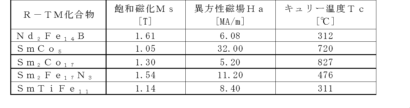
一方、図1の4f電子雲からわかるように、Ce原子は4f電子1個を有し、非常に扁平な電子雲を示す。従って、Ce2Fe14B化合物は、電子雲の形状からは、高い一軸結晶磁気異方性Kuを有していると考えることができる。しかるに、表2に示されるR2Fe14B化合物(R2Fe14B金属間化合物)の磁気特性のとおり、Ce2Fe14B化合物の一軸結晶磁気異方性Kuは、Y2Fe14B化合物と同程度である。イットリウムYは、元々4f電子を有していないため、Y2Fe14B化合物の一軸結晶磁気異方性KuはFe副格子に由来するものである。Ce2Fe14B化合物のKuは、Y2Fe14B化合物のそれと同程度であることから、これは、ほとんどがFe副格子に由来し、Ce原子は4f電子を何らかの理由により失っていると考えることができる。また、Ce2Fe14B化合物のキュリー温度Tcは、427K(154℃)で、実用的には少し低いが、Feの一部をCoで置換することにより向上可能である。
On the other hand, as can be seen from the 4f electron cloud in FIG. 1, the Ce atom has one 4f electron, and shows a very flat electron cloud. Accordingly, the Ce 2 Fe 14 B compound can be considered to have a high uniaxial crystal magnetic anisotropy Ku from the shape of the electron cloud. However, according to the magnetic properties of the R 2 Fe 14 B compound (R 2 Fe 14 B intermetallic compound) shown in Table 2, the uniaxial crystal magnetic anisotropy Ku of the Ce 2 Fe 14 B compound is Y 2 Fe 14 B It is the same level as the compound. Since yttrium Y originally does not have 4f electrons, the uniaxial crystal magnetic anisotropy Ku of the Y 2 Fe 14 B compound is derived from the Fe sublattice. Since the Ku of the Ce 2 Fe 14 B compound is similar to that of the Y 2 Fe 14 B compound, this is mostly due to the Fe sublattice, and the Ce atom has lost 4f electrons for some reason. Can think. The Curie temperature Tc of the Ce 2 Fe 14 B compound is 427 K (154 ° C.), which is practically a little lower, but can be improved by substituting part of Fe with Co.
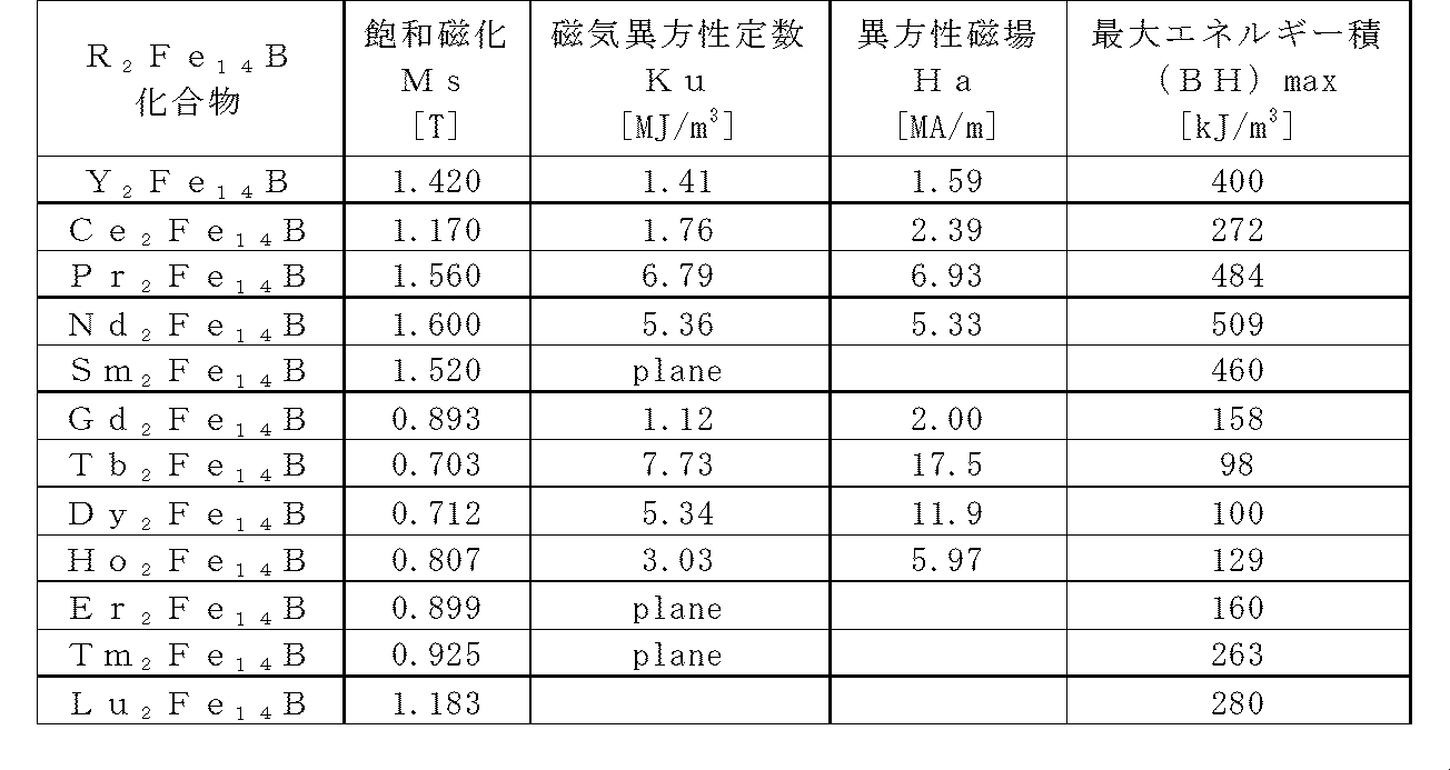
Ce2Fe14B化合物のCe原子が4f原子を失っていることは、R2Fe14B化合物の格子定数を原子番号順に並べて比較したときのCe2Fe14B化合物の格子定数の特異的な変化からも裏付けられる。図2は、R2Fe14B化合物の格子定数の変化を示すグラフである。Ce2Fe14B化合物のa軸及びc軸の格子定数は、変化の傾向からは、La2Fe14B化合物とPr2Fe14B化合物との中間の値を取ると考えられるが、Ce2Fe14Bのa軸及びc軸の格子定数は、この傾向から外れて、両方共に落ち込んでいる。これは、Ce原子から4f電子が失われ、その結果、原子半径が収縮したため、格子定数も減少したためと考えられる。Ce原子から4f電子が失われた詳細なメカニズムは、伝導電子のバンドの詳細な計算によって明らかにすることができるが、R2Fe14B化合物の伝導電子のバンドの上限エネルギー(フェルミエネルギー:EF)より、Ceの4f電子のバンドが高いエネルギー準位をもつため、4f電子が伝導電子と混成して、伝導バンド側に移行してCe原子のサイトから失われたためと推測される。
The fact that the Ce atom of the Ce 2 Fe 14 B compound has lost the 4f atom is that the lattice constant of the Ce 2 Fe 14 B compound when comparing the lattice constants of the R 2 Fe 14 B compound in order of atomic numbers is unique. It is supported by changes. FIG. 2 is a graph showing changes in the lattice constant of the R 2 Fe 14 B compound. Ce 2 lattice constant of a-axis and c-axis of the Fe 14 B compound, from the trend of change is considered to take an intermediate value between the La 2 Fe 14 B compound and Pr 2 Fe 14 B compound, Ce 2 The lattice constants of the a-axis and c-axis of Fe 14 B deviate from this tendency, and both are depressed. This is presumably because the 4f electrons were lost from the Ce atoms, and as a result, the atomic radius contracted and the lattice constant was also reduced. The detailed mechanism of the loss of 4f electrons from the Ce atom can be clarified by detailed calculation of the conduction electron band, but the upper limit energy (Fermi energy: E of the conduction electron band of the R 2 Fe 14 B compound). From F ), it is presumed that the 4f electron band of Ce has a high energy level, so that the 4f electron is mixed with the conduction electron, moved to the conduction band side and lost from the site of the Ce atom.
従来、希土類元素としてCeを主体とするRFeB磁石を開発する試みは、RFeB磁石に関する膨大な開発検討がなされたにもかかわらず、検討されてこなかった。希土類元素としてCeを用いたRFeB磁石については、例えば、CeをNd、Tb、Prを主体とするRFeB磁石に添加した、Nd(Ce)FeB磁石、Tb(Ce)FeB磁石、Pr(Ce)FeB磁石の形での開発事例はあるが、これは、単に、Ceによる置換によりNd、Tb又はPrの磁性を犠牲にして、Nd、Tb又はPrの使用量を減らしただけのものである。具体的には、特開昭59-46008号公報(特許文献1)及び特開昭59-64733号公報(特許文献2)の実施例には、各々、NdとCeとの混合組成の磁石及びTbとCeとの混合組成の磁石が示されている。
Conventionally, an attempt to develop an RFeB magnet mainly composed of Ce as a rare earth element has not been studied even though an enormous development study on the RFeB magnet has been made. For RFeB magnets using Ce as a rare earth element, for example, Nd (Ce) FeB magnets, Tb (Ce) FeB magnets, Pr (Ce) FeBs in which Ce is added to an RFeB magnet mainly composed of Nd, Tb, and Pr. There are development cases in the form of magnets, but this is merely a reduction in the amount of Nd, Tb or Pr used at the expense of Nd, Tb or Pr magnetism by substitution with Ce. Specifically, in the examples of JP-A-59-46008 (Patent Document 1) and JP-A-59-64733 (Patent Document 2), a magnet having a mixed composition of Nd and Ce, respectively, A magnet with a mixed composition of Tb and Ce is shown.
上述したように、Ce原子は、本来4f電子を1個有するものであるが、Ce2Fe14B化合物においては、Ce原子の4f電子が伝導電子と混成し、Ce原子から4f電子が失われている。Ce原子における4f電子の喪失は、Ce2Fe14B化合物に限られたものではなく、セリウム-遷移金属化合物(Ce-TM化合物)であるCeCo5、Ce2Co17、Ce2Fe17、CeTiFe11などにおいて一般的に見られる現象である。これらの化合物では、上述したR2Fe14B化合物におけるCe2Fe14B化合物と同様な格子定数の落ち込みが見られ、一軸結晶磁気異方性Kuも低い。そのため、Ceを主体とするCe-TM化合物を永久磁石材料とする検討は、Co副格子の結晶磁気異方性が高いCeCo5化合物が、Ce(CoFeCu)5磁石として実用化された例を除き、永久磁石の候補材料として、Ce-TM化合物であるCe2Fe14B化合物が着目されることはなかった。
As described above, the Ce atom originally has one 4f electron, but in the Ce 2 Fe 14 B compound, the 4f electron of the Ce atom is mixed with the conduction electron, and the 4f electron is lost from the Ce atom. ing. The loss of 4f electrons in the Ce atom is not limited to the Ce 2 Fe 14 B compound, but is a cerium-transition metal compound (Ce-TM compound) CeCo 5 , Ce 2 Co 17 , Ce 2 Fe 17 , CeTiFe It is a phenomenon commonly seen in 11 etc. In these compounds, a drop in lattice constant similar to that of the Ce 2 Fe 14 B compound in the R 2 Fe 14 B compound described above is observed, and the uniaxial magnetocrystalline anisotropy Ku is also low. Therefore, the study of using a Ce-TM compound mainly composed of Ce as a permanent magnet material was conducted except for an example in which a CeCo 5 compound having a high crystal magnetic anisotropy of a Co sublattice was put into practical use as a Ce (CoFeCu) 5 magnet. As a candidate material for permanent magnets, a Ce 2 Fe 14 B compound, which is a Ce-TM compound, has not attracted attention.
本発明は、本来高い一軸結晶磁気異方性Kuを与えるポテンシャルがあるCe原子のCe-TM化合物であるCe2Fe14B化合物において、Ce原子に4f電子を呼び戻して孤立化させて、Ce原子が本来有している磁性(磁気モーメントと磁気異方性)を回復させており、このCe原子の孤立化を、Ce2Fe14B化合物のCeの一部を他の元素、具体的には、Ca、Sr及びBaからなる群より選ばれる1種以上のアルカリ土類金属元素に置換した組成とし、これにより、結晶格子を拡張させた構造としたことにより達成したものである。その結果、重希土類元素の含有量を極力低減して、重希土類元素を積極的に用いることなく、更には、重希土類元素を全く用いることなくても、Ceを主体とするRFeB磁石によって、実用上十分な保磁力Hcを得ている。
In the present invention, a Ce 2 Fe 14 B compound, which is a Ce-TM compound of a Ce atom that originally has a potential to give a high uniaxial crystal magnetic anisotropy Ku, recalls 4f electrons to the Ce atom and isolates it, Has recovered its inherent magnetism (magnetic moment and magnetic anisotropy), and this Ce atom isolation can be achieved by replacing part of Ce in the Ce 2 Fe 14 B compound with other elements, specifically , Ca, Sr, and Ba. The composition is substituted with one or more alkaline earth metal elements selected from the group consisting of Ca, Sr, and Ba, thereby achieving a structure in which the crystal lattice is expanded. As a result, it is possible to reduce the content of heavy rare earth elements as much as possible without using heavy rare earth elements actively, or even using no heavy rare earth elements at all. A sufficient coercive force Hc is obtained.
上述した観点によりCe-TM化合物のCe原子が本来有している磁性を回復させることに着眼した発明は、従来は、全くなされていなかった。例えば、特開昭59-177346号公報(特許文献6)には、Ca還元法により作製したFe-B-R合金又はFe-Co-B-R合金の原料合金において、還元後の洗浄で除去しきれなかったCaが0.01wt%以下の含有率で含まれていることが示されているが、特開昭59-46008号公報(特許文献1)の表1にも示されているように、従来、Ce2Fe14B化合物などのCe-TM化合物は、磁気特性が低いと認識されており、この場合の希土類元素Rの具体例はNdのみで、Ceを用いた具体例はない。
From the above viewpoint, the invention that focuses on restoring the magnetic properties inherent in the Ce atom of the Ce-TM compound has never been made. For example, in Japanese Patent Application Laid-Open No. 59-177346 (Patent Document 6), an Fe—BR alloy or an alloy alloy of Fe—Co—BR alloy produced by a Ca reduction method is removed by washing after reduction. Although it has been shown that Ca that has not been exhausted is contained at a content of 0.01 wt% or less, it is also shown in Table 1 of Japanese Patent Application Laid-Open No. 59-46008 (Patent Document 1). Conventionally, Ce-TM compounds such as Ce 2 Fe 14 B compounds have been recognized as having low magnetic properties. In this case, the specific example of the rare earth element R is only Nd, and there is no specific example using Ce. .
また、特開平3-219056号公報(特許文献8)には、Ce13Fe77B8合金に酸化カルシウムCaOを添加して焼結磁石としたR2TM14B1(R=Ceなど)型正方晶を主相とする希土類磁石合金において、耐食性が向上することが示されているが、この場合、カルシウムを酸化カルシウムとして添加しているので、カルシウム原子は、酸化カルシウム結晶として、R2TM14B1(R=Ceなど)型正方晶とは別に存在していると考えられる。
JP-A-3-219056 (Patent Document 8) describes a R 2 TM 14 B 1 (R = Ce or the like) type in which a calcium oxide CaO is added to a Ce 13 Fe 77 B 8 alloy to form a sintered magnet. It has been shown that the corrosion resistance of a rare earth magnet alloy having a tetragonal crystal as the main phase is improved. In this case, since calcium is added as calcium oxide, calcium atoms are converted into calcium oxide crystals as R 2 TM. It is thought that it exists separately from 14 B 1 (R = Ce, etc.) type tetragonal crystal.
更に、特開平4-268052号公報(特許文献9)には、MとしてBa、Sr、Caなどを添加したR-Fe-M-B-C系合金磁石において、ホウ素Bの含有量を抑えて炭素Cを添加することで、炭素Cを含有する粒界相の磁気温度特性を改善し、更に、M添加元素により粒界相への炭素Cの拡散が促進され、不可逆減磁が減少することが示されているが、この場合、炭素Cが必須成分であり、また、特開昭59-177346号公報(特許文献6)の場合と同様、従来、Ce2Fe14B化合物などのCe-TM化合物は磁気特性が低いと認識されており、この場合の希土類元素Rの具体例も、Nd又はNdとCe以外の希土類元素との組み合わせのみで、Ceを用いた具体例はない。
Furthermore, Japanese Patent Laid-Open No. 4-26852 (Patent Document 9) discloses that an R—Fe—M—B—C—C-based alloy magnet to which Ba, Sr, Ca, or the like is added as M has a reduced boron B content. By adding carbon C, the magnetic temperature characteristics of the grain boundary phase containing carbon C are improved, and further, diffusion of carbon C into the grain boundary phase is promoted by the M addition element, and irreversible demagnetization is reduced. In this case, carbon C is an essential component, and as in the case of Japanese Patent Application Laid-Open No. 59-177346 (Patent Document 6), a Ce— such as a Ce 2 Fe 14 B compound has been conventionally used. It is recognized that the TM compound has low magnetic properties, and the specific example of the rare earth element R in this case is only a combination of Nd or Nd and a rare earth element other than Ce, and there is no specific example using Ce.
本発明は、いわゆるNd2Fe14B構造の相(2-14-1相)を有するRFeB磁石であり、かつRがCeを主体とする磁石である。本発明の希土類永久磁石は、Ca、Sr及びBaからなる群より選ばれる1種以上のアルカリ土類金属元素を含む組成となっている。本発明のアルカリ土類金属元素が、どのような相にどのような形態で含有されているかは定かではないが、本発明の希土類元素の主成分がCeである希土類永久磁石の高い磁気特性を考慮すれば、Ceを主体とするRFeB磁石の2-14-1相のCeのサイトの一部において、アルカリ土類金属原子により結晶格子が拡張した構造、特に、アルカリ土類金属原子でCeサイトが置換された構造を有しているものと推測される。本発明の希土類永久磁石は、このような構造により、Ce原子の本質的な磁気異方性を回復させている点において、2-14-1相としてCe2Fe14B構造の相を有する従来のRFeB磁石と全く異なるものである。本発明においては、Ce原子に磁気異方性を回復させるために、Ce原子の4f電子1個を孤立化させること、言い換えれば、この電子を、伝導電子との混成ではなく、4f軌道に呼び戻して、局在電子として存在させることが必要であり、Ce2Fe14Bの基本結晶構造を壊すことなく、格子定数を大きくし、結晶格子中のCe原子が収容される空間を広くすることによって、それを実現している。
The present invention is an RFeB magnet having a so-called Nd 2 Fe 14 B structure phase (2-14-1 phase), and R is a magnet mainly composed of Ce. The rare earth permanent magnet of the present invention has a composition containing one or more alkaline earth metal elements selected from the group consisting of Ca, Sr and Ba. It is not certain in what form the alkaline earth metal element of the present invention is contained, but the high magnetic properties of the rare earth permanent magnet of which the main component of the rare earth element of the present invention is Ce. In consideration, a structure in which the crystal lattice is expanded by an alkaline earth metal atom in a part of the Ce site of the 2-14-1 phase of the RFeB magnet mainly composed of Ce, particularly, the Ce site with an alkaline earth metal atom. Is presumed to have a substituted structure. The rare earth permanent magnet of the present invention has a Ce 2 Fe 14 B structure phase as a 2-14-1 phase in that the essential magnetic anisotropy of Ce atoms is recovered by such a structure. This is completely different from the RFeB magnet. In the present invention, in order to restore the magnetic anisotropy of the Ce atom, one 4f electron of the Ce atom is isolated, in other words, this electron is called back to the 4f orbit instead of being mixed with the conduction electron. Therefore, it is necessary to exist as localized electrons, by increasing the lattice constant without breaking the basic crystal structure of Ce 2 Fe 14 B, and by widening the space for accommodating Ce atoms in the crystal lattice. Have realized it.
本発明の希土類永久磁石は、Yを含む希土類元素から選ばれる1種以上と、Feと、Bとを含み、不可避不純物を含んでいてもよい。不可避不純物は、例えば、粉末焼結プロセスなどにおいて混入する元素であり、主に、O(酸素)、C(炭素)、N(窒素)、H(水素)などが挙げられる。また、本発明の希土類永久磁石は、不可避不純物を除く組成が、下記組成式(1)
(R1-xAEx)y(Fe1-aMa)100-y-zBz (1)
(式中、Rは、Yを含む希土類元素から選ばれる1種以上であり、かつY、La、Ce、Pr、Nd,Pm、Sm及びEuからなる群より選ばれる1種以上の軽希土類元素を70原子%以上含み、Rの50原子%以上はCeであり、AEは、Ca、Sr及びBaからなる群より選ばれる1種以上のアルカリ土類金属元素であり、Mは、Cu、Ni、Ti、Mo、Zr、Hf、Ga、Al及びSiからなる群より選ばれる1種以上の元素であり、x、y及びzは、各々、0<x≦0.4、10≦y≦20、4≦z≦12を満たす正数、aは、0又は0<a≦0.1を満たす正数である。)
で示される希土類永久磁石である。そして、結晶相として、いわゆるNd2Fe14B構造の相(正方晶Nd2Fe14B型希土類金属間化合物の相)、即ち2-14-1相を主相とする(例えば、結晶相のうち2-14-1相が最大の相である)RFeB磁石である。 The rare earth permanent magnet of the present invention contains one or more selected from rare earth elements including Y, Fe, and B, and may contain inevitable impurities. Inevitable impurities are elements mixed in, for example, a powder sintering process, and mainly include O (oxygen), C (carbon), N (nitrogen), H (hydrogen), and the like. In addition, the rare earth permanent magnet of the present invention has a composition excluding inevitable impurities having the following composition formula (1):
(R 1-x AE x ) y (Fe 1-a M a ) 100-yz B z (1)
(In the formula, R is at least one selected from rare earth elements including Y, and at least one light rare earth element selected from the group consisting of Y, La, Ce, Pr, Nd, Pm, Sm, and Eu. 70 atomic% or more, 50 atomic% or more of R is Ce, AE is one or more alkaline earth metal elements selected from the group consisting of Ca, Sr and Ba, and M is Cu, Ni , Ti, Mo, Zr, Hf, Ga, Al and Si are one or more elements selected from the group consisting of x, y and z, where 0 <x ≦ 0.4 and 10 ≦ y ≦ 20, respectively. 4 is a positive number that satisfies 4 ≦ z ≦ 12, and a is a positive number that satisfies 0 or 0 <a ≦ 0.1.)
Is a rare earth permanent magnet. As a crystal phase, a so-called Nd 2 Fe 14 B structure phase (tetragonal Nd 2 Fe 14 B type rare earth intermetallic compound phase), that is, a 2-14-1 phase (for example, a crystal phase) RFeB magnet (2-14-1 phase is the largest).
本発明の希土類永久磁石に含まれるRで示される元素は、Yを含む希土類元素から選ばれる1種以上であり、Rは、Y、La、Ce、Pr、Nd,Pm、Sm及びEuからなる群より選ばれる1種以上の軽希土類元素を70原子%以上、好ましくは80原子%以上、より好ましくは90原子%以上含み、Rが、Y、La、Ce、Pr、Nd,Pm、Sm及びEuからなる群より選ばれる1種以上の軽希土類元素のみからなる、即ち、Rの100%が、Y、La、Ce、Pr、Nd,Pm、Sm及びEuからなる群より選ばれる1種以上の軽希土類元素であることが、更に好ましい。
The element represented by R contained in the rare earth permanent magnet of the present invention is at least one selected from rare earth elements including Y, and R is composed of Y, La, Ce, Pr, Nd, Pm, Sm and Eu. One or more light rare earth elements selected from the group comprising 70 atomic% or more, preferably 80 atomic% or more, more preferably 90 atomic% or more, and R is Y, La, Ce, Pr, Nd, Pm, Sm and It consists of only one or more light rare earth elements selected from the group consisting of Eu, that is, one or more selected from the group consisting of Y, La, Ce, Pr, Nd, Pm, Sm and Eu, where 100% of R The light rare earth element is more preferable.
また、本発明の希土類永久磁石は、LR2Fe14B(LRはY、La、Ce、Pr、Nd,Pm、Sm及びEuからなる群より選ばれる1種以上の軽希土類元素であり、好ましくはその一部はCa、Sr及びBaからなる群より選ばれる1種以上のアルカリ土類金属元素で置換されている。)で示される正方晶の希土類金属間化合物の相(2-14-1相)を含んでいることが好ましく、この相のキュリー温度が500K以上であることがより好ましい。
The rare earth permanent magnet of the present invention is LR 2 Fe 14 B (LR is one or more light rare earth elements selected from the group consisting of Y, La, Ce, Pr, Nd, Pm, Sm and Eu, preferably Is partially substituted with one or more alkaline earth metal elements selected from the group consisting of Ca, Sr and Ba.) Phase), and the Curie temperature of this phase is more preferably 500K or more.
また、希土類元素Rの50原子%以上、好ましくは60原子%以上、より好ましくは70原子%以上、更に好ましくは95原子%以上、特に好ましくは100原子%がCeである。RがCe以外の希土類元素を含む場合、スティーブンス因子αJが0又は負の軽希土類元素、例えば、La、Pr、Ndなどを含んでいることが好ましく、希土類元素Rが、Ceと、La、Pr及びNdからなる群より選ばれる1種以上の希土類元素とからなることがより好ましい。一方、Y、La、Ce、Pr、Nd,Pm、Sm及びEuの軽希土類元素以外の重希土類元素、即ち、Gd、Tb、Dy、Ho、Er、Tm、Yb及びLuからなる群より選ばれる1種以上の重希土類元素を含む場合、それらの含有率は、Rで示される希土類元素中、20原子%以下、好ましくは10原子%以下、より好ましくは5原子%以下であることが好ましい。
Further, 50 atom% or more of the rare earth element R, preferably 60 atom% or more, more preferably 70 atom% or more, still more preferably 95 atom% or more, particularly preferably 100 atom% is Ce. When R contains a rare earth element other than Ce, the Stevens factor αJ preferably contains 0 or a negative light rare earth element such as La, Pr, Nd, etc., and the rare earth element R contains Ce, La, More preferably, it comprises one or more rare earth elements selected from the group consisting of Pr and Nd. On the other hand, heavy rare earth elements other than light rare earth elements such as Y, La, Ce, Pr, Nd, Pm, Sm and Eu, that is, selected from the group consisting of Gd, Tb, Dy, Ho, Er, Tm, Yb and Lu. In the case where one or more heavy rare earth elements are contained, the content thereof is preferably 20 atomic% or less, preferably 10 atomic% or less, more preferably 5 atomic% or less in the rare earth element represented by R.
原子が収容される空間を広げる格子拡張の例としては、R2Fe17N3やRTiFe11Nのように、N原子やC原子をR原子の周囲に侵入型で導入する方法が挙げられる。この方法を適用すれば、RFeB磁石においても、R2Fe14BNxのようなN原子をR原子の周囲に侵入型で導入する方法は可能であるが、このような侵入型の窒素化合物は1,000℃以下で分解し、RNx、Fe-Me(Meは、Ti等の添加金属)などになる。侵入型の窒素化合物は、微粉として有機樹脂バインダと混合し、圧粉成形してボンド磁石として使用することができるが、焼結磁石を対象とする場合は、侵入型で導入する方法による格子拡張は適用できない。
As an example of lattice expansion that expands the space in which atoms are accommodated, there is a method in which N atoms or C atoms are introduced in the vicinity of R atoms in an interstitial manner, such as R 2 Fe 17 N 3 or RTiFe 11 N. If this method is applied, even in an RFeB magnet, a method of introducing N atoms such as R 2 Fe 14 BN x around the R atoms in an interstitial manner is possible, but such interstitial nitrogen compounds are Decomposes at 1,000 ° C. or lower to become RN x , Fe—Me (Me is an additive metal such as Ti) or the like. Interstitial nitrogen compounds can be mixed with organic resin binders as fine powders, compacted and used as bonded magnets, but when sintered magnets are used, lattice expansion by the method of introducing interstitial types Is not applicable.
Ce原子が収容される空間を広げる格子拡張のために、希土類永久磁石の組成において、Ceの一部を、Ce原子より大きな原子半径を有する元素で置換すること、特に、Ceサイトの一部を、Ce原子より大きな原子半径を有する原子で置換することは有効である。例えば、表3に示されるように、La原子は、希土類原子の中では原子半径が最も大きいため、La原子であっても、格子拡張が可能である。Ce原子の原子半径は、表3に示されるように、Nd原子やPr原子とほぼ同等である。格子拡張の一つの目安は、Nd2Fe14B化合物と同等か、又はそれより大きな格子定数を実現することである。しかし、Ce原子の置換率が高すぎると、Ce原子が減少して、Ce原子が本来有する磁気異方性に基づく磁気特性が得られず、結果として異方性が大幅に低下し、また、2-14-1相が安定でなくなってしまうため、La原子より大きな原子半径を有し、2-14-1相を安定に保ったままでCe原子の置換が可能であり、かつできるだけ少ない量で格子拡張を実現できる原子による置換が好ましい。この観点から、本発明においては、表3に示されるように、Ce原子より大きな原子半径を有するCa、Sr及びBaからなる群より選ばれる1種以上のアルカリ土類金属元素を所定量添加した組成により、Ce原子が本来有する磁気異方性に基づく高い磁気特性を得ている。
In order to expand the lattice to expand the space in which Ce atoms are accommodated, in the composition of the rare earth permanent magnet, a part of Ce is replaced with an element having an atomic radius larger than that of Ce atoms. Substitution with an atom having an atomic radius larger than that of Ce atom is effective. For example, as shown in Table 3, since La atoms have the largest atomic radius among rare earth atoms, lattice expansion is possible even with La atoms. As shown in Table 3, the atomic radius of Ce atoms is almost equal to Nd atoms and Pr atoms. One measure of lattice expansion is to achieve a lattice constant that is equal to or greater than that of the Nd 2 Fe 14 B compound. However, if the substitution rate of Ce atoms is too high, Ce atoms will decrease, and magnetic properties based on the magnetic anisotropy inherent in Ce atoms will not be obtained, resulting in a significant decrease in anisotropy, Since the 2-14-1 phase becomes unstable, it has a larger atomic radius than the La atom, the Ce atom can be replaced while keeping the 2-14-1 phase stable, and in the smallest possible amount Substitution with atoms capable of realizing lattice expansion is preferred. From this point of view, in the present invention, as shown in Table 3, a predetermined amount of one or more alkaline earth metal elements selected from the group consisting of Ca, Sr and Ba having an atomic radius larger than Ce atoms was added. High magnetic properties based on the magnetic anisotropy inherent in Ce atoms are obtained by the composition.
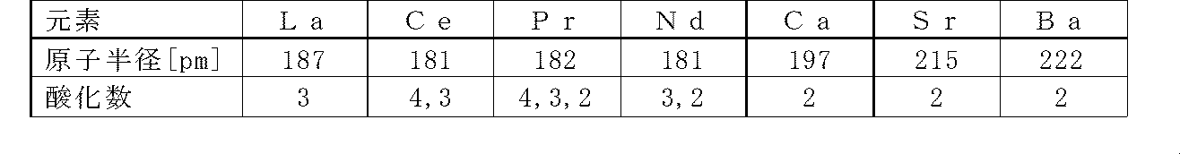
なお、このような、結晶格子のR原子のサイトを原子半径の異なる原子で一部置換し、構造を安定化したり、R原子が本来もつ磁性を発現させたり、また、遷移金属原子副格子と希土類原子副格子との間の相互作用を調整したりすることは、本発明のCeを主体とするRFeB磁石以外でも可能と考えられる。
It should be noted that the R atom sites in the crystal lattice are partially substituted with atoms having different atomic radii to stabilize the structure, develop the inherent magnetism of the R atoms, It is considered possible to adjust the interaction with the rare earth atom sublattice other than the RFeB magnet mainly composed of Ce of the present invention.
アルカリ土類金属元素AEの含有比率(上記組成式(1)中のx)は、希土類元素Rに対して最大0.4まで可能である。この含有率xが0.4を超えると、2-14-1相の構造が不安定になり、かつCe量が低下して一軸結晶磁気異方性Kuが大きく低下する。含有比率xが0.01未満の場合、格子拡張が不十分で、Ce原子の4f電子が十分に回復せず、十分な一軸結晶磁気異方性Kuが得られない場合がある。このように、アルカリ土類金属元素AEの含有比率xは、Ce原子の磁気異方性の回復と、2-14-1相の構造におけるCe原子の電子軌道に起因する磁気異方性の喪失の回避との両立の観点から、0<x≦0.4の範囲を満たす正数であり、0.01<x、特に0.05≦xであることが好ましく、また、x≦0.30、特にx≦0.25、とりわけx≦0.20であることが好ましい。
The content ratio of the alkaline earth metal element AE (x in the composition formula (1)) can be up to 0.4 with respect to the rare earth element R. When the content x exceeds 0.4, the structure of the 2-14-1 phase becomes unstable, and the Ce amount decreases, resulting in a significant decrease in uniaxial crystal magnetic anisotropy Ku. When the content ratio x is less than 0.01, lattice expansion is insufficient, 4f electrons of Ce atoms are not sufficiently recovered, and sufficient uniaxial crystal magnetic anisotropy Ku may not be obtained. As described above, the content ratio x of the alkaline earth metal element AE is that the recovery of the magnetic anisotropy of the Ce atom and the loss of the magnetic anisotropy caused by the electron orbit of the Ce atom in the structure of the 2-14-1 phase. Is a positive number satisfying the range of 0 <x ≦ 0.4, preferably 0.01 <x, particularly preferably 0.05 ≦ x, and x ≦ 0.30. In particular, it is preferable that x ≦ 0.25, especially x ≦ 0.20.
本発明の希土類永久磁石の組成は、RがCeのみの場合及びRがCeと、Ce以外の希土類元素とを含む場合のいずれの場合においても、少なくとも一部のCe原子において、Ce原子の4f軌道に電子1個が回復し、Ce原子の4f電子1個が孤立化して、2-14-1相が一軸結晶磁気異方性Kuを示している組成であることが必要である。特に、例えば、希土類元素R中の50原子%以上、特に60原子%以上、とりわけ70原子%以上が、4f電子1個の軌道角運動量を有するCe原子であることが好ましい。
The composition of the rare earth permanent magnet of the present invention is such that at least a part of Ce atoms is 4f of Ce atoms in both cases where R is only Ce and R contains Ce and a rare earth element other than Ce. It is necessary that one electron is recovered in the orbit, one 4f electron of Ce atom is isolated, and the 2-14-1 phase has a uniaxial magnetocrystalline anisotropy Ku. In particular, for example, 50 atom% or more, particularly 60 atom% or more, particularly 70 atom% or more in the rare earth element R is preferably a Ce atom having an orbital angular momentum of one 4f electron.
また、Ce2Fe14B化合物におけるFe副格子は、Ceサイトが拡張しても一軸結晶磁気異方性Kuの値に変化を与えないと考えられる。一方、Ceサイトが拡張し、Ce原子の4f軌道に電子1個が回復して、4f電子1個が孤立化したCe原子の割合が高くなることによって、異方性磁場Haが増大する。従って、アルカリ土類金属元素AEを含む本発明の希土類永久磁石の異方性磁場Haは、アルカリ土類金属元素AEを含まない組成、即ち、上記組成式(1)においてx=0の場合に相当する組成の合金の異方性磁場Haに対する割合として、好ましくは1.5倍以上、特に2倍以上、とりわけ2.5倍以上であることが好ましい。
Further, it is considered that the Fe sublattice in the Ce 2 Fe 14 B compound does not change the value of the uniaxial crystal magnetic anisotropy Ku even when the Ce site is expanded. On the other hand, the Ce site expands, one electron recovers in the 4f orbit of the Ce atom, and the ratio of the Ce atom in which one 4f electron is isolated increases to increase the anisotropic magnetic field Ha. Therefore, the anisotropic magnetic field Ha of the rare earth permanent magnet of the present invention containing the alkaline earth metal element AE has a composition not containing the alkaline earth metal element AE, that is, when x = 0 in the composition formula (1). The ratio of the alloy of the corresponding composition to the anisotropic magnetic field Ha is preferably 1.5 times or more, particularly preferably 2 times or more, and particularly preferably 2.5 times or more.
本発明の希土類永久磁石においては、主成分であるFeを置換する元素を含んでいてもよい。この置換元素Mは、NdFeB磁石などのRFeB磁石において用いられる添加元素が本発明の希土類永久磁石においても適用可能であり、特に限定されるものではないが、主に保磁力向上に資するもの、例えば、Cu、Ni、Ti、Mo、Zr、Hf等の遷移金属元素や、遷移金属元素ではないがGa、Al、Siなどの典型元素が挙げられ、保磁力向上には、遷移金属元素と典型元素との組み合わせも有効である。そのため、置換元素Mは含まれていなくてもよいが、Cu、Ni、Ti、Mo、Zr、Hf、Ga、Al及びSiからなる群より選ばれる1種以上の元素を置換元素Mとして含んでいることが好適である。置換元素Mの含有比率(上記組成式(1)中のa)は、0又は0<a≦0.1を満たす正数であり、0.01≦aであることが好ましいが、含有比率が高すぎると飽和磁化Msが著しく低下するおそれがあるため、a≦0.07、特にa≦0.05であることが好ましい。
The rare earth permanent magnet of the present invention may contain an element that substitutes Fe as a main component. The substitution element M is an additive element used in an RFeB magnet such as an NdFeB magnet, and can be applied to the rare earth permanent magnet of the present invention, and is not particularly limited. Transition metal elements such as Cu, Ni, Ti, Mo, Zr, and Hf, and typical elements such as Ga, Al, and Si, which are not transition metal elements, and transition metal elements and typical elements can be used to improve coercive force. The combination with is also effective. Therefore, the substitution element M may not be included, but one or more elements selected from the group consisting of Cu, Ni, Ti, Mo, Zr, Hf, Ga, Al, and Si are included as the substitution element M. It is preferable that The content ratio of the substitution element M (a in the above composition formula (1)) is a positive number satisfying 0 or 0 <a ≦ 0.1, and preferably 0.01 ≦ a. If it is too high, the saturation magnetization Ms may be remarkably lowered. Therefore, it is preferable that a ≦ 0.07, particularly a ≦ 0.05.
本発明の希土類永久磁石においては、不可避不純物を除く組成の全体を100として、希土類元素R及びアルカリ土類金属元素AEの含有比率(上記組成式(1)中のy)は、10≦y≦20を満たす正数の範囲である。y<10であると、希土類永久磁石の合金組織中に、Ceリッチ相が減少し、かつFe相、Fe3B相などの磁気的ソフト相が生成し、焼結体密度や保磁力低下の観点から好ましくない。y>20であると、希土類永久磁石の合金組織中に、Ceリッチ相のうち、非磁性の相が増加し、磁性相である2-14-1相の比率が低下するため好ましくない。高密度焼結体の生成に資するCeリッチ相と、高磁気特性に資する2-14-1相のバランスから、希土類元素R及びアルカリ土類金属元素AEの含有比率yは、12≦yであることが好ましく、y≦18、特にy≦16であることが好ましい。
In the rare earth permanent magnet of the present invention, the total composition excluding inevitable impurities is 100, and the content ratio of the rare earth element R and the alkaline earth metal element AE (y in the composition formula (1)) is 10 ≦ y ≦ A positive number range satisfying 20. If y <10, the Ce-rich phase decreases in the alloy structure of the rare earth permanent magnet, and a magnetic soft phase such as an Fe phase or Fe 3 B phase is generated, resulting in a decrease in sintered body density or coercive force. It is not preferable from the viewpoint. If y> 20, the non-magnetic phase in the Ce-rich phase increases in the alloy structure of the rare earth permanent magnet, and the ratio of the 2-14-1 phase, which is the magnetic phase, decreases. The content ratio y of the rare earth element R and the alkaline earth metal element AE is 12 ≦ y from the balance between the Ce-rich phase contributing to the formation of the high-density sintered body and the 2-14-1 phase contributing to the high magnetic properties. It is preferable that y ≦ 18, particularly y ≦ 16.
本発明の希土類永久磁石においては、不可避不純物を除く組成の全体を100として、ホウ素Bの含有比率(上記組成式(1)中のz)は、4≦z≦12を満たす正数の範囲である。z<4であると、希土類永久磁石の合金組織中に、Fe相、R2Fe17相などの磁気的ソフト相が生成し、焼結体密度や保磁力低下の観点から好ましくない。z>12であると、Fe3B相などの磁気的ソフト相や、その他非磁性相が生成し、保磁力低下や飽和磁化低下を招く。高密度焼結体の生成に資するCeリッチ相と、高磁気特性に資する2-14-1相のバランスから、ホウ素Bの含有比率zは、5≦z、特に6≦zであることが好ましく、z≦10であることが好ましい。
In the rare earth permanent magnet of the present invention, the total composition excluding inevitable impurities is 100, and the boron B content ratio (z in the above composition formula (1)) is a positive number in the range satisfying 4 ≦ z ≦ 12. is there. When z <4, a magnetic soft phase such as an Fe phase or an R 2 Fe 17 phase is generated in the alloy structure of the rare earth permanent magnet, which is not preferable from the viewpoint of a sintered body density and a reduction in coercive force. When z> 12, a magnetic soft phase such as an Fe 3 B phase and other nonmagnetic phases are generated, resulting in a decrease in coercive force and a decrease in saturation magnetization. From the balance between the Ce-rich phase that contributes to the formation of a high-density sintered body and the 2-14-1 phase that contributes to high magnetic properties, the boron B content ratio z is preferably 5 ≦ z, particularly 6 ≦ z. , Z ≦ 10 is preferable.
本発明は、磁性粉を使用するボンド磁石でもよいが、焼結磁石であることが好ましい。焼結磁石は、主に粉末冶金法により作製される異方性焼結磁石が好適である。焼結磁石の場合、見かけ密度が真密度の95%以上の異方性焼結磁石とすることができる。
The present invention may be a bonded magnet using magnetic powder, but is preferably a sintered magnet. As the sintered magnet, an anisotropic sintered magnet produced mainly by a powder metallurgy method is suitable. In the case of a sintered magnet, an anisotropic sintered magnet having an apparent density of 95% or more of the true density can be obtained.
本発明の希土類永久磁石を焼結磁石として製造する場合、例えば、上記組成式(1)で示される合金微粉を、単一の金属及び/又は2種以上の金属からなる合金と、ホウ素及び/又は金属とホウ素とからなる合金とを溶融し、粉砕することにより調製する工程、
合金微粉に一軸方向に磁場を印加して、磁場方向に合金微粉を配向させる工程、
配向した合金微粉を圧縮して成形する工程、
圧縮された成形体を焼結する工程、及び
焼結体を熱処理する工程
を含む方法により製造することができる。 When the rare earth permanent magnet of the present invention is produced as a sintered magnet, for example, an alloy fine powder represented by the above composition formula (1) is converted into an alloy composed of a single metal and / or two or more metals, boron and / or Or a step of melting and pulverizing an alloy composed of a metal and boron,
Applying a magnetic field in a uniaxial direction to the alloy fine powder and orienting the alloy fine powder in the magnetic field direction;
A process of compressing and molding oriented alloy fines;
It can be manufactured by a method including a step of sintering the compacted compact and a step of heat-treating the sintered body.
具体的には、まず、構成元素に応じて、希土類金属R、RとFeとの合金等のRの合金、アルカリ土類金属AE、AEの合金、Fe、Feの合金、置換元素M、Mの合金、ホウ素B、フェロボロンなどから選ばれる、金属、合金又はホウ素を原料とし、原料を構成元素が所定の比率となるように秤量する。ここで、蒸気圧の高い原料は、上記組成式(1)で示される合金の作製中や粉砕中、粉末冶金の手法による焼結中などの製造過程において蒸発することを考慮して、若干多めに秤量することができる。次に、秤量した原料を、抵抗加熱、高周波誘導加熱などにより、融点以上に加熱して溶融し、所定の構成元素の合金とする。溶融工程は、合金が酸化又は窒化しないように、希ガスなどの不活性雰囲気中又は真空中で行うことが好ましい。
Specifically, first, depending on the constituent elements, R alloys such as rare earth metals R, alloys of R and Fe, alkaline earth metals AE, AE alloys, Fe, Fe alloys, substitution elements M, M A metal, an alloy, or boron selected from the above alloys, boron B, ferroboron, and the like is used as a raw material, and the raw material is weighed so that the constituent elements have a predetermined ratio. Here, the raw material with a high vapor pressure is slightly larger in consideration of evaporation during the production process such as during the production of the alloy represented by the composition formula (1), during the pulverization, and during the sintering by the powder metallurgy technique. Can be weighed. Next, the weighed raw material is heated to a melting point or higher by resistance heating, high-frequency induction heating, or the like, and is made into an alloy of predetermined constituent elements. The melting step is preferably performed in an inert atmosphere such as a rare gas or in vacuum so that the alloy is not oxidized or nitrided.
次に、得られた合金(バルク合金)は、一種又は複数種の粉砕方法(例えば、ジョークラッシャー、ブラウンミル、ジェットミルによる多段階粉砕)を適用して、例えば平均粒径1~20μmの微粉とする。粉砕工程は、合金が酸化しないように、窒素ガス雰囲気、希ガスなどの不活性雰囲気中又は真空中で行うことが好ましい。
Next, the obtained alloy (bulk alloy) is applied to one or a plurality of pulverization methods (for example, multistage pulverization using a jaw crusher, a brown mill, or a jet mill), for example, a fine powder having an average particle diameter of 1 to 20 μm. And The pulverization step is preferably performed in an inert atmosphere such as a nitrogen gas atmosphere or a rare gas or in a vacuum so that the alloy is not oxidized.
次に、得られた合金微粉を、一軸方向に磁場を印加して、磁場方向に合金微粉を配向させる。具体的には、合金微粉のC軸を磁場方向に配向させる。次に、この配向状態を維持したまま(好ましくは、磁場を印加したまま)合金微粉を圧縮して成形する。印加する磁場は、配向工程及び圧縮成形工程のいずれにおいても、方向と強度が均一で高いほど好ましいが、装置の物理的制約もあるため、一般的には、400kA/m以上1,200kA/m以下とする。
Next, a magnetic field is applied to the obtained alloy fine powder in a uniaxial direction to orient the alloy fine powder in the magnetic field direction. Specifically, the C axis of the alloy fine powder is oriented in the magnetic field direction. Next, the alloy fine powder is compressed and molded while maintaining this orientation state (preferably while applying a magnetic field). The applied magnetic field is preferably higher in direction and strength in both the orientation process and the compression molding process. However, since there are physical limitations of the apparatus, generally 400 kA / m to 1,200 kA / m. The following.
次に、圧縮された成形体を、組成により異なるが、800~1,200℃の温度で、好ましくは窒素ガス雰囲気、希ガスなどの不活性雰囲気中又は真空中で焼結する。この焼結工程では、得られる焼結体の見かけ密度が真密度の95%以上となるように焼結して緻密化することが好ましい。そして、焼結工程の後、得られた焼結体に対して、組成に適した温度、例えば600~800℃の温度で、好ましくは窒素ガス雰囲気、希ガスなどの不活性雰囲気中又は真空中で熱処理(時効処理)を行う。このような方法で製造した焼結磁石は、成形工程における磁場配向を反映して、異方性焼結磁石として得ることができる。実用上は、更に、所定形状に切削などの加工や、使用目的に応じてメッキ、PVD、塗装などの耐食性被覆などを行うことができる。
Next, the compressed molded body is sintered at a temperature of 800 to 1,200 ° C., preferably in an inert atmosphere such as a nitrogen gas atmosphere or a rare gas, or in a vacuum, depending on the composition. In this sintering step, it is preferable to sinter and densify so that the apparent density of the obtained sintered body is 95% or more of the true density. After the sintering step, the obtained sintered body is subjected to a temperature suitable for the composition, for example, a temperature of 600 to 800 ° C., preferably in an inert atmosphere such as a nitrogen gas atmosphere or a rare gas, or in a vacuum. Heat treatment (aging treatment) is performed at The sintered magnet manufactured by such a method can be obtained as an anisotropic sintered magnet reflecting the magnetic field orientation in the molding process. Practically, it is possible to perform a process such as cutting into a predetermined shape, and a corrosion-resistant coating such as plating, PVD, or painting depending on the purpose of use.
一方、ボンド磁石を製造する場合は、例えば、上述した焼結磁石の製造方法と同様の方法でバルク合金を得、これを、粉砕し、例えば、ブラウンミル後の粗粉とジェットミル後の微粉とを混合した合金微粉とし、更に、有機樹脂バインダ(例えばエポキシ樹脂など)と混合して、合金微粉と有機樹脂バインダとの混合粉を磁場中で配向させた後、圧粉成形を行い成形体とし、成形体を加熱硬化して、圧縮成形異方性ボンド磁石とすることができる。また、合金微粉を磁場中で配向させた後、圧粉成形を行い成形体とし、成形体に、液状の樹脂組成物を含浸させて、加熱硬化して、圧縮成形異方性ボンド磁石とすることもできる。更に、合金微粉と有機樹脂バインダ(特に、熱可塑性樹脂)との混合粉を、射出成形機により加熱、射出成形し、有機樹脂バインダが溶融している状態で磁場を印加することで、射出成形異方性ボンド磁石とすることも可能である。
On the other hand, when manufacturing a bonded magnet, for example, a bulk alloy is obtained by the same method as the above-described sintered magnet manufacturing method, and this is pulverized, for example, coarse powder after Brown mill and fine powder after jet mill And then mixed with an organic resin binder (for example, epoxy resin), and the mixed powder of the alloy fine powder and organic resin binder is oriented in a magnetic field, and then compacted by compacting. Then, the molded body can be heat-cured to form a compression-molded anisotropic bonded magnet. Also, after orienting the alloy fine powder in a magnetic field, compacting is performed to obtain a compact, and the compact is impregnated with a liquid resin composition and heat-cured to obtain a compression-molded anisotropic bonded magnet. You can also. Furthermore, mixed powder of alloy fine powder and organic resin binder (especially thermoplastic resin) is heated and injection molded by an injection molding machine, and a magnetic field is applied in a state where the organic resin binder is melted, thereby injection molding. An anisotropic bonded magnet can also be used.
本発明の希土類永久磁石においては、通常、不可避不純物が含まれる。この不可避不純物は、上記組成式(1)の構成元素以外の元素であり、特に限定されるものではないが、希土類永久磁石の実製造において、原料中の不純物や、製造中の雰囲気などによって混入するものであり、不可避不純物には、主に、酸素、窒素、炭素、水素などが含まれる。例えば、酸素Oは、主に、合金粉砕工程での酸化により又は原料由来で混入し、原料由来での混入もあり得る。窒素Nは、例えば、粉砕工程においてN2ガスを用いることにより混入する場合があり、原料由来での混入もあり得る。また、炭素Cも、溶融工程や焼結工程での混入や原料由来で混入する。更に、粉砕工程で水素Hを使用して微粉化した場合、水素Hが微量混入することもある。その他の元素も原料由来で含まれる場合がある。
The rare earth permanent magnet of the present invention usually contains inevitable impurities. This inevitable impurity is an element other than the constituent element of the composition formula (1), and is not particularly limited. However, in actual production of a rare earth permanent magnet, it is mixed depending on impurities in the raw material, atmosphere in production, etc. Inevitable impurities mainly include oxygen, nitrogen, carbon, hydrogen, and the like. For example, oxygen O is mainly mixed by oxidation in the alloy crushing process or derived from the raw material, and may be mixed from the raw material. Nitrogen N may be mixed by using N 2 gas in the pulverization step, for example, and may be mixed from the raw material. Carbon C is also mixed from the melting process and the sintering process and from the raw material. Furthermore, when hydrogen H is used in the pulverization process and pulverized, a small amount of hydrogen H may be mixed. Other elements may also be included from the raw material.
不可避不純物の含有率は、特定の含有率を定めてその値に制御できるものではないが、永久磁石の磁気特性に寄与しない不可避不純物はできるだけ少ない方が望ましい。そのため、不可避不純物の含有率は、通常、5,000ppm(質量比)以下、特に1,000ppm(質量比)以下であることが好ましく、特に、酸素、窒素、炭素及び水素の含有率が、3,000ppm(質量比)以下、特に1,000ppm(質量比)以下であることが好ましい。
The content of inevitable impurities cannot be controlled by setting a specific content, but it is desirable that the content of inevitable impurities not contributing to the magnetic properties of the permanent magnet is as small as possible. Therefore, the content of inevitable impurities is usually preferably 5,000 ppm (mass ratio) or less, particularly 1,000 ppm (mass ratio) or less, and in particular, the oxygen, nitrogen, carbon, and hydrogen content is 3 or less. It is preferably 1,000 ppm (mass ratio) or less, particularly 1,000 ppm (mass ratio) or less.
なお、構成元素であるホウ素Bの原料としては、ホウ素単体(純ボロン)を用いることが可能であるが、一般的には、より廉価なFe-B合金(フェロボロン)が原料として使用される。Fe-B合金を作製する場合、Alテルミット反応で還元するため、Fe-B合金には、Alが一定割合で混入する。そのため、原料中の金属不純物としてAlが含まれることがあるが、Alは、本発明の希土類永久磁石において、置換元素Mとして含まれていてよい元素であり、Alは、保磁力増大に寄与するため、原料由来のAlは一定量であれば許容される。
In addition, as a raw material for boron B, which is a constituent element, boron alone (pure boron) can be used, but generally a cheaper Fe—B alloy (ferroboron) is used as a raw material. When an Fe—B alloy is produced, Al is mixed in the Fe—B alloy at a constant rate because it is reduced by an Al thermit reaction. Therefore, Al may be included as a metal impurity in the raw material, but Al is an element that may be included as the substitution element M in the rare earth permanent magnet of the present invention, and Al contributes to an increase in coercive force. Therefore, a certain amount of Al derived from the raw material is allowed.
上述したとおり、Ce原子は本来4f電子を1個有しており、4f電子のスティーブンス因子(αJ:4f電子雲の形状を決める定数)が負であり、図1に示されるように、非常に扁平な電子雲となっている。4f電子雲の形状は、球形から歪んだ電子雲になるほど、大きな磁気異方性が発現する。4f電子を1個有しているCe原子は非常に扁平な4f電子雲を有しているため、4f電子を1個有しているCe原子による2-14-1相によって、Ce以外の軽希土類元素や重希土類元素による2-14-1相より、更に高い一軸結晶磁気異方性Kuを得ることができる。4f電子を1個有しているCe原子を含む2-14-1相を含む本発明の希土類永久磁石は、保磁力増大のための重希土類元素の置換がなされていなくても、高い磁気特性を有している。また、Ce原子は軽希土類元素であるため、CeとFeの磁気モーメントは平行であり、飽和磁化Msの低下がほとんどない。更に、Ceのクラーク数は、希土類元素の中で最も大きく、希土類元素の中では豊富にあるため、資源的な問題が生じる可能性が最も低い。
As described above, the Ce atom originally has one 4f electron, and the Stevens factor (αJ: constant that determines the shape of the 4f electron cloud) of the 4f electron is negative, and as shown in FIG. It is a flat electron cloud. As the shape of the 4f electron cloud changes from a spherical shape to a distorted electron cloud, a larger magnetic anisotropy appears. A Ce atom having one 4f electron has a very flat 4f electron cloud, and therefore, a light atom other than Ce is obtained by the 2-14-1 phase of the Ce atom having one 4f electron. A higher uniaxial magnetocrystalline anisotropy Ku can be obtained than the 2-14-1 phase of rare earth elements or heavy rare earth elements. The rare earth permanent magnet of the present invention containing the 2-14-1 phase containing Ce atoms having one 4f electron has high magnetic properties even if heavy rare earth elements are not substituted to increase the coercive force. have. Further, since Ce atoms are light rare earth elements, the magnetic moments of Ce and Fe are parallel, and there is almost no decrease in saturation magnetization Ms. Furthermore, Ce has the largest number of Clarkes among the rare earth elements and is abundant among the rare earth elements, so that it is least likely to cause resource problems.
本発明によれば、希土類元素の主成分がCeである希土類永久磁石において、保磁力Hcが、例えば、400kA/m以上、特に800kA/m以上、とりわけ1.2MA/m以上の希土類永久磁石を提供することができる。また、本発明によれば、希土類元素の主成分がCeである希土類永久磁石において、飽和磁化Msが、例えば、1T以上、特に1.1T以上、とりわけ1.2T以上の希土類永久磁石を提供することができる。
According to the present invention, in a rare earth permanent magnet whose main component of the rare earth element is Ce, a rare earth permanent magnet having a coercive force Hc of, for example, 400 kA / m or more, particularly 800 kA / m or more, particularly 1.2 MA / m or more. Can be provided. Further, according to the present invention, there is provided a rare earth permanent magnet having a saturation magnetization Ms of, for example, 1T or more, particularly 1.1T or more, particularly 1.2T or more in a rare earth permanent magnet whose main component is a rare earth element. be able to.
以下、実施例及び比較例を示して本発明を具体的に説明するが、本発明は下記の実施例に制限されるものではない。
Hereinafter, the present invention will be specifically described with reference to examples and comparative examples, but the present invention is not limited to the following examples.
[実施例1~6、比較例1~3]
希土類元素RとしてCe及びLa、アルカリ土類金属AE(Ca、Sr又はBa)、Fe、置換元素M(Cu又はGa)及びホウ素B(いずれも純度99質量%以上)を、溶融時の蒸発を考慮して、希土類元素Rとアルカリ土類金属AEについては、所定の組成に対して0.5原子%ずつ多めにして秤量した。CeとLaとの原子比は85:15とした。次に、秤量した原料を、高周波真空溶解炉のルツボに充填した後、炉内を1×10⁻³Paまで減圧し、高周波コイルに高周波交番電流を印加して昇温した。放射温度計で、ルツボ内が900℃を超えた時点で、炉内にArを導入して10Paとした。これは希土類元素やアルカリ土類金属の蒸発を抑制するためである。各原料が十分溶解し、溶湯が均一化した後、水冷鋳造板の上に溶湯を流し込んで、急冷して合金とした。 [Examples 1 to 6, Comparative Examples 1 to 3]
Ce and La, rare earth element R, alkaline earth metal AE (Ca, Sr or Ba), Fe, substitution element M (Cu or Ga) and boron B (both having a purity of 99% by mass or more) are evaporated during melting. Considering this, the rare earth element R and the alkaline earth metal AE were weighed by 0.5 atomic% more than the predetermined composition. The atomic ratio of Ce and La was 85:15. Next, after filling the weighed raw materials into a crucible of a high-frequency vacuum melting furnace, the inside of the furnace was depressurized to 1 × 10 −3 Pa, and a high-frequency alternating current was applied to the high-frequency coil to raise the temperature. When the inside of the crucible exceeded 900 ° C. with a radiation thermometer, Ar was introduced into the furnace to 10 Pa. This is to suppress evaporation of rare earth elements and alkaline earth metals. After each raw material was sufficiently melted and the molten metal became uniform, the molten metal was poured onto a water-cooled cast plate and rapidly cooled to obtain an alloy.
次に、得られた合金を粉砕した。粗粉砕は、ジョークラッシャーとブラウンミルとで200メッシュアンダーまで粉砕し、更に、N2気流によるジェットミルで平均粒径4μmまで微粉砕した。得られた合金微粉は、粒度分布をもっているが、概ね1μm以上10μm以下の範囲にある。微粉砕がN2気流中で行われているため、合金微粉の酸化は抑制されており、合金に対する酸素の含有率は概ね0.3質量%以下であった。ICP(誘導結合プラズマ発光分析)にて組成分析を行い、上記組成式(1)のx、y、z及びaの各値を求めた。組成分析から求めたこれらの値を表4に示す。
Next, the obtained alloy was pulverized. Coarse pulverization was performed by pulverizing to 200 mesh under with a jaw crusher and a brown mill, and further pulverizing to an average particle size of 4 μm with a jet mill using N 2 airflow. The obtained alloy fine powder has a particle size distribution, but is generally in the range of 1 μm to 10 μm. Since the fine pulverization is performed in an N 2 gas stream, the oxidation of the alloy fine powder is suppressed, and the oxygen content in the alloy is approximately 0.3% by mass or less. Composition analysis was performed by ICP (inductively coupled plasma emission spectrometry), and each value of x, y, z and a in the composition formula (1) was determined. These values obtained from the composition analysis are shown in Table 4.
各々の合金微粉について、XRD(X線回折測定)を行った。実施例1~6では、回折ピークのほとんどが、2-14-1相のピークとして指数付けでき、この相が主相で、ほぼ2-14-1相のみであった。一方、比較例1~3では、2-14-1相として指数付けできるピークの他に、合金化していないα-Fe相や、Ce2Fe17相として指数付けできるピークが存在し、2-14-1相以外の相が含まれていた。
Each alloy fine powder was subjected to XRD (X-ray diffraction measurement). In Examples 1 to 6, most of the diffraction peaks could be indexed as peaks of the 2-14-1 phase, and this phase was the main phase and was almost only the 2-14-1 phase. On the other hand, in Comparative Examples 1 to 3, in addition to the peak that can be indexed as the 2-14-1 phase, there are α-Fe phases that are not alloyed and peaks that can be indexed as the Ce 2 Fe 17 phase. Phases other than the 14-1 phase were included.
次に、合金微粉を正方形の充填孔をもつダイス金型中に充填し、800kA/mの静磁場を合金微粉に印加して、合金微粉のC軸を磁場方向に配向させ、配向状態を維持したまま100kg/cm2(約9.8MPa)の圧力で圧粉成形し、成形体を作製した。次に、熱磁気曲線を求めるため、得られた成形体をVSM(振動試料型磁力計)にて加熱昇温し、合金微粉の磁化が消滅する温度(キュリー温度Tc)を測定した。キュリー温度Tcは、熱磁気曲線のα-Fe相及びCe2Fe17相以外の相を2-14-1相とみなして、これを2-14-1相のキュリー温度とした。
Next, the alloy fine powder is filled into a die mold having square filling holes, a static magnetic field of 800 kA / m is applied to the alloy fine powder, the C axis of the alloy fine powder is oriented in the magnetic field direction, and the orientation state is maintained. As it was, compacting was performed at a pressure of 100 kg / cm 2 (about 9.8 MPa) to produce a compact. Next, in order to obtain a thermomagnetic curve, the obtained compact was heated and heated with a VSM (vibrating sample magnetometer), and the temperature at which the magnetization of the alloy fine powder disappeared (Curie temperature Tc) was measured. Regarding the Curie temperature Tc, the phases other than the α-Fe phase and the Ce 2 Fe 17 phase in the thermomagnetic curve were regarded as the 2-14-1 phase, and this was set as the Curie temperature of the 2-14-1 phase.
また、同様の方法で得られた成形体に、液状接着剤を浸み込ませて、接着剤を室温で固化させてボンド磁石を作製し、ボンド磁石の磁場配向方向と垂直方向磁化曲線をVSMで4MA/mの磁場まで測定し、飽和磁化Msと異方性磁場(理論最大保磁力)Haとを求めた。両磁化曲線の交点が、簡易的に異方性磁場Haとみなせる。両磁化曲線の交差が4MA/mの印加磁場までで生じない場合は、両磁化曲線を外挿してその交点を求めた。なお、測定された飽和磁化Msの値にはα-Fe相などの磁化が重畳しているため、この場合の飽和磁化Msは2-14-1相のみの値ではない。また、比較例1及び2では、合金化されていないFe(α-Fe相)が多く、異方性磁場Haを正確に評価することができなかった。一方、比較例3では、相対的にα-Fe相が少なかったため、熱磁気曲線から量を推定してその分を差し引いて、2-14-1相の異方性磁場Haの値とした。比較例3では、SEM-EDX(走査電子顕微鏡-エネルギー分散型X線分光法)の元素マッピングにより、α-Fe相及びCe2Fe17相を確認したが、異方性磁場Haの推定におけるα-Fe相の差し引き量は、SEM-EDXによるα-Fe相の量にほぼ対応していた。
Further, a liquid adhesive is soaked in a molded body obtained by the same method, and the adhesive is solidified at room temperature to produce a bonded magnet. The magnetic field orientation direction and the perpendicular magnetization curve of the bonded magnet are represented by VSM. Then, the saturation magnetization Ms and the anisotropic magnetic field (theoretical maximum coercive force) Ha were determined. The intersection of both magnetization curves can be simply regarded as the anisotropic magnetic field Ha. When the intersection of the two magnetization curves did not occur up to the applied magnetic field of 4 MA / m, the intersection point was obtained by extrapolating the two magnetization curves. Note that the saturation magnetization Ms in this case is not only the value of the 2-14-1 phase because the measured saturation magnetization Ms is superposed with the magnetization of the α-Fe phase or the like. In Comparative Examples 1 and 2, the amount of unalloyed Fe (α-Fe phase) was large, and the anisotropic magnetic field Ha could not be accurately evaluated. On the other hand, in Comparative Example 3, since the α-Fe phase was relatively small, the amount was estimated from the thermomagnetic curve, and the amount was subtracted to obtain the value of the anisotropic magnetic field Ha of the 2-14-1 phase. In Comparative Example 3, the α-Fe phase and the Ce 2 Fe 17 phase were confirmed by elemental mapping of SEM-EDX (scanning electron microscope-energy dispersive X-ray spectroscopy). The amount of subtraction of the —Fe phase almost corresponded to the amount of α-Fe phase by SEM-EDX.

以上の結果から、実施例の異方性磁場Haが、比較例の異方性磁場Haに比べて大きく向上しており、本発明の希土類永久磁石において、Ce原子が磁気異方性を回復しているものと推測される。一方、飽和磁化Ms及びキュリー温度Tcの相対的な増加は、主にFe-Fe間距離の増大によるFeの磁気モーメントの増大効果によると推測される。
From the above results, the anisotropic magnetic field Ha of the example is greatly improved as compared with the anisotropic magnetic field Ha of the comparative example, and in the rare earth permanent magnet of the present invention, Ce atoms recover the magnetic anisotropy. It is presumed that On the other hand, it is presumed that the relative increase in the saturation magnetization Ms and the Curie temperature Tc is mainly due to the effect of increasing the magnetic moment of Fe due to the increase in the Fe-Fe distance.
[実施例7~12、比較例4]
原料として、希土類元素RをCe及びPr、置換元素MをSi、Cu、Ga又はNiとし、CeとPrとの原子比を85:15とし、ホウ素Bを用いずにFe-B合金(フェロボロン)を用いた以外は、実施例1と同様の方法で、合金微粉及び成形体を作製した。 [Examples 7 to 12, Comparative Example 4]
As raw materials, the rare earth element R is Ce and Pr, the substitution element M is Si, Cu, Ga, or Ni, the atomic ratio of Ce and Pr is 85:15, and Fe—B alloy (ferroboron) is used without boron B. An alloy fine powder and a compact were produced in the same manner as in Example 1 except that was used.
実施例1と同様の方法で、合金微粉の組成及び物性、並びに成形体又はボンド磁石の物性及び磁気特性を評価した。結果を表5に示す。なお、Fe-B合金を用いたことにより、いずれの合金微粉にも置換元素MとしてAlが含まれていた。実施例8におけるAlとSiとの原子比は2:1、実施例9におけるAlとCuとの原子比は2:2、実施例10におけるAlとGaとの原子比は1:1、実施例11におけるCaとSrとの原子比は1:3、AlとNiとの原子比は3:1、実施例12におけるBaとSrとの原子比は3:2(上記組成式(1)のx中、Baが0.15、Srが0.10)、AlとNiとの原子比は2:1(上記組成式(1)のa中、Alが0.0066、Niが0.0034)であった。なお、比較例4ではCaの量が多すぎて2-14-1相以外も多数の相が生成していたため、2-14-1相の磁気特性を評価できなかった。
In the same manner as in Example 1, the composition and physical properties of the alloy fine powder, and the physical properties and magnetic properties of the compact or bonded magnet were evaluated. The results are shown in Table 5. In addition, Al was contained as the substitution element M in any alloy fine powder by using the Fe-B alloy. In Example 8, the atomic ratio between Al and Si is 2: 1, the atomic ratio between Al and Cu in Example 9 is 2: 2, and the atomic ratio between Al and Ga in Example 10 is 1: 1. 11, the atomic ratio of Ca and Sr is 1: 3, the atomic ratio of Al and Ni is 3: 1, and the atomic ratio of Ba and Sr in Example 12 is 3: 2 (x in the above composition formula (1)). Ba is 0.15, Sr is 0.10), and the atomic ratio between Al and Ni is 2: 1 (in the composition formula (1), Al is 0.0066 and Ni is 0.0034). there were. In Comparative Example 4, since the amount of Ca was too large and many phases other than the 2-14-1 phase were generated, the magnetic properties of the 2-14-1 phase could not be evaluated.

[実施例13~17]
原料として、希土類元素RをCe及びNd、置換元素MをSi、Cu、Ga又はNiとし、CeとNdとの原子比を95:5とし、ホウ素Bを用いずにFe-B合金(フェロボロン)を用いた以外は、実施例1と同様の方法で、合金微粉を作製した。 [Examples 13 to 17]
As raw materials, the rare earth element R is Ce and Nd, the substitution element M is Si, Cu, Ga or Ni, the atomic ratio of Ce and Nd is 95: 5, and Fe—B alloy (ferroboron) without boron B is used. An alloy fine powder was produced in the same manner as in Example 1 except that was used.
次に、合金微粉をダイス金型中に充填し、800kA/mの静磁場を合金微粉に印加して微粉C軸を磁場方向に配向させ、配向状態を維持したまま上下パンチによりダイス金型に充填された合金微粉を100kg/cm2(約9.8MPa)の圧力で圧縮成形し、成形体を作製した。次に、得られた成形体を、焼結炉に入れ、10-5Pa台まで減圧し、その後、Arガスを導入して、約1,100℃の温度で10PaのArガス雰囲気中で焼結し、更に、熱処理炉にて、約1,050~1,150℃で熱処理(時効処理)して焼結磁石を得た。得られた焼結磁石は、見かけ密度が真密度の95%以上まで焼結し、緻密化していた。
Next, the alloy fine powder is filled into the die mold, and a static magnetic field of 800 kA / m is applied to the alloy fine powder to orient the fine powder C axis in the magnetic field direction, and the die mold is formed by the upper and lower punches while maintaining the orientation state. The filled alloy fine powder was compression molded at a pressure of 100 kg / cm 2 (about 9.8 MPa) to produce a molded body. Next, the obtained molded body is put into a sintering furnace, and the pressure is reduced to a level of 10 −5 Pa. After that, Ar gas is introduced and sintered in an Ar gas atmosphere of 10 Pa at a temperature of about 1,100 ° C. Further, the sintered magnet was obtained by heat treatment (aging treatment) at about 1,050 to 1,150 ° C. in a heat treatment furnace. The obtained sintered magnet was sintered and densified to an apparent density of 95% or more of the true density.
実施例1と同様の方法で、合金微粉の組成及び物性を評価した。結果を表6に示す。なお、Fe-B合金を用いたことにより、いずれの合金微粉にも置換元素MとしてAlが含まれていた。実施例14におけるAlとSiとの原子比は4:1、実施例15におけるAlとCuとの原子比は2:3、実施例16におけるAlとGaとの原子比は1:1、実施例17におけるCaとSrとの原子比は2:1(上記組成式(1)のx中、Caが0.134、Srが0.066)、AlとNiとの原子比は5:1であった。一方、合金に対する酸素の含有率は概ね0.3質量%以下であった。更に、成形体の代わりに焼結磁石を用いた以外は、実施例1と同様の方法で、キュリー温度Tcを評価し、焼結磁石を用いてBHトレーサーにてヒステリシス曲線を測定して、保磁力Hcを評価した。結果を表6に示す。
The composition and physical properties of the alloy fine powder were evaluated in the same manner as in Example 1. The results are shown in Table 6. In addition, Al was contained as the substitution element M in any alloy fine powder by using the Fe-B alloy. The atomic ratio of Al and Si in Example 14 is 4: 1, the atomic ratio of Al and Cu in Example 15 is 2: 3, and the atomic ratio of Al and Ga in Example 16 is 1: 1. In FIG. 17, the atomic ratio of Ca and Sr was 2: 1 (in the composition formula (1) x, Ca was 0.134, Sr was 0.066), and the atomic ratio of Al and Ni was 5: 1. It was. On the other hand, the oxygen content in the alloy was generally 0.3% by mass or less. Further, the Curie temperature Tc was evaluated in the same manner as in Example 1 except that a sintered magnet was used instead of the compact, and the hysteresis curve was measured with a BH tracer using the sintered magnet. The magnetic force Hc was evaluated. The results are shown in Table 6.
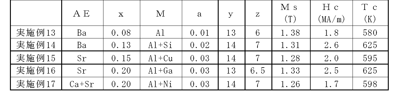
Claims (11)
- Yを含む希土類元素から選ばれる1種以上と、Feと、Bとを含み、不可避不純物を含んでいてもよい希土類永久磁石であって、
上記不可避不純物を除く組成が、下記組成式(1)
(R1-xAEx)y(Fe1-aMa)100-y-zBz (1)
(式中、Rは、Yを含む希土類元素から選ばれる1種以上であり、かつY、La、Ce、Pr、Nd,Pm、Sm及びEuからなる群より選ばれる1種以上の軽希土類元素を70原子%以上含み、Rの50原子%以上はCeであり、AEは、Ca、Sr及びBaからなる群より選ばれる1種以上のアルカリ土類金属元素であり、Mは、Cu、Ni、Ti、Mo、Zr、Hf、Ga、Al及びSiからなる群より選ばれる1種以上の元素であり、x、y及びzは、各々、0<x≦0.4、10≦y≦20、4≦z≦12を満たす正数、aは、0又は0<a≦0.1を満たす正数である。)
で示されることを特徴とする希土類永久磁石。 A rare earth permanent magnet including one or more selected from rare earth elements including Y, Fe, and B, and may include inevitable impurities,
The composition excluding the above inevitable impurities is the following composition formula (1)
(R 1-x AE x ) y (Fe 1-a M a ) 100-yz B z (1)
(In the formula, R is at least one selected from rare earth elements including Y, and at least one light rare earth element selected from the group consisting of Y, La, Ce, Pr, Nd, Pm, Sm, and Eu. 70 atomic% or more, 50 atomic% or more of R is Ce, AE is one or more alkaline earth metal elements selected from the group consisting of Ca, Sr and Ba, and M is Cu, Ni , Ti, Mo, Zr, Hf, Ga, Al and Si are one or more elements selected from the group consisting of x, y and z, where 0 <x ≦ 0.4 and 10 ≦ y ≦ 20, respectively. 4 is a positive number that satisfies 4 ≦ z ≦ 12, and a is a positive number that satisfies 0 or 0 <a ≦ 0.1.)
A rare earth permanent magnet characterized by the following. - 上記組成式(1)中のRが、Y、La、Ce、Pr、Nd,Pm、Sm及びEuからなる群より選ばれる1種以上の軽希土類元素のみからなることを特徴とする請求項1記載の希土類永久磁石。 2. The R in the composition formula (1) is composed of only one or more light rare earth elements selected from the group consisting of Y, La, Ce, Pr, Nd, Pm, Sm and Eu. The rare earth permanent magnet described.
- 上記組成式(1)中のRの50原子%以上が、4f電子1個の軌道角運動量を有するCe原子であることを特徴とする請求項1又は2記載の希土類永久磁石。 3. The rare earth permanent magnet according to claim 1, wherein 50 atomic% or more of R in the composition formula (1) is a Ce atom having an orbital angular momentum of one 4f electron.
- LR2Fe14B(LRはY、La、Ce、Pr、Nd,Pm、Sm及びEuからなる群より選ばれる1種以上の軽希土類元素であり、その一部はCa、Sr及びBaからなる群より選ばれる1種以上のアルカリ土類金属元素で置換されている。)で示される正方晶の希土類金属間化合物の相を含むことを特徴とする請求項1~3のいずれか1項記載の希土類永久磁石。 LR 2 Fe 14 B (LR is one or more light rare earth elements selected from the group consisting of Y, La, Ce, Pr, Nd, Pm, Sm and Eu, part of which is composed of Ca, Sr and Ba. 4. A phase of a tetragonal rare earth intermetallic compound represented by the formula (1), which is substituted with one or more alkaline earth metal elements selected from the group: Rare earth permanent magnet.
- 上記正方晶の希土類金属間化合物の相のキュリー温度が500K以上であることを特徴とする請求項4記載の希土類永久磁石。 The rare earth permanent magnet according to claim 4, wherein the Curie temperature of the phase of the tetragonal rare earth intermetallic compound is 500K or more.
- 上記組成式(1)中のRが、Ce、又はCeと、La、Pr及びNdからなる群より選ばれる1種以上の希土類元素とからなることを特徴とする請求項1~5のいずれか1項記載の希土類永久磁石。 The R in the composition formula (1) is composed of Ce or Ce and one or more rare earth elements selected from the group consisting of La, Pr and Nd. 2. A rare earth permanent magnet according to item 1.
- 上記組成式(1)中のx、y及びzが、各々、0.01<x≦0.30、12≦y≦18、5≦z≦10を満たす正数、aが、0又は0<a≦0.07を満たす正数であることを特徴とする請求項1~6のいずれか1項記載の希土類永久磁石。 X, y and z in the composition formula (1) are positive numbers satisfying 0.01 <x ≦ 0.30, 12 ≦ y ≦ 18, and 5 ≦ z ≦ 10, respectively, a is 0 or 0 < The rare earth permanent magnet according to any one of claims 1 to 6, wherein the rare earth permanent magnet is a positive number satisfying a≤0.07.
- 上記組成式(1)中のx、y及びzが、各々、0.05≦x≦0.25、12≦y≦16、6≦z≦10を満たす正数、aが、0.01≦a≦0.05を満たす正数であることを特徴とする請求項1~6のいずれか1項記載の希土類永久磁石。 X, y, and z in the composition formula (1) are positive numbers satisfying 0.05 ≦ x ≦ 0.25, 12 ≦ y ≦ 16, and 6 ≦ z ≦ 10, respectively, and a is 0.01 ≦ 7. The rare earth permanent magnet according to claim 1, wherein the rare earth permanent magnet is a positive number satisfying a ≦ 0.05.
- 見かけ密度が真密度の95%以上の異方性焼結磁石であることを特徴とする請求項1~8のいずれか1項記載の希土類永久磁石。 The rare earth permanent magnet according to any one of claims 1 to 8, wherein the rare earth permanent magnet is an anisotropic sintered magnet having an apparent density of 95% or more of a true density.
- Yを含む希土類元素から選ばれる1種以上と、Feと、Bとを含み、不可避不純物を含んでいてもよい希土類永久磁石を製造する方法であって、
上記不可避不純物を除く組成が、下記組成式(1)
(R1-xAEx)y(Fe1-aMa)100-y-zBz (1)
(式中、Rは、Yを含む希土類元素から選ばれる1種以上であり、かつY、La、Ce、Pr、Nd,Pm、Sm及びEuからなる群より選ばれる1種以上の軽希土類元素を70原子%以上含み、Rの50原子%以上はCeであり、AEは、Ca、Sr及びBaからなる群より選ばれる1種以上のアルカリ土類金属元素であり、Mは、Cu、Ni、Ti、Mo、Zr、Hf、Ga、Al及びSiからなる群より選ばれる1種以上の元素であり、x、y及びzは、各々、0<x≦0.4、10≦y≦20、4≦z≦12を満たす正数、aは、0又は0<a≦0.1を満たす正数である。)
で示される合金微粉を、単一の金属及び/又は2種以上の金属からなる合金と、ホウ素及び/又は金属とホウ素とからなる合金とを溶融し、粉砕することにより調製する工程、
上記合金微粉に一軸方向に磁場を印加して、磁場方向に上記合金微粉を配向させる工程、
配向した合金微粉を圧縮して成形する工程、
圧縮された成形体を焼結する工程、及び
焼結体を熱処理する工程
を含むことを特徴とする希土類焼結磁石の製造方法。 A method for producing a rare earth permanent magnet containing one or more selected from rare earth elements including Y, Fe, and B, and optionally containing inevitable impurities,
The composition excluding the above inevitable impurities is the following composition formula (1)
(R 1-x AE x ) y (Fe 1-a M a ) 100-yz B z (1)
(In the formula, R is at least one selected from rare earth elements including Y, and at least one light rare earth element selected from the group consisting of Y, La, Ce, Pr, Nd, Pm, Sm, and Eu. 70 atomic% or more, 50 atomic% or more of R is Ce, AE is one or more alkaline earth metal elements selected from the group consisting of Ca, Sr and Ba, and M is Cu, Ni , Ti, Mo, Zr, Hf, Ga, Al and Si are one or more elements selected from the group consisting of x, y and z, where 0 <x ≦ 0.4 and 10 ≦ y ≦ 20, respectively. 4 is a positive number that satisfies 4 ≦ z ≦ 12, and a is a positive number that satisfies 0 or 0 <a ≦ 0.1.)
A step of preparing an alloy fine powder represented by the following by melting and grinding a single metal and / or an alloy composed of two or more metals and boron and / or an alloy composed of a metal and boron;
Applying a magnetic field in a uniaxial direction to the alloy fine powder and orienting the alloy fine powder in the magnetic field direction;
A process of compressing and molding oriented alloy fines;
A method for producing a rare earth sintered magnet, comprising: a step of sintering a compacted compact, and a step of heat treating the sintered body. - 見かけ密度が真密度の95%以上の異方性焼結磁石を製造することを特徴とする請求項10記載の希土類焼結磁石の製造方法。 The method for producing a rare earth sintered magnet according to claim 10, wherein an anisotropic sintered magnet having an apparent density of 95% or more of the true density is produced.
Applications Claiming Priority (2)
| Application Number | Priority Date | Filing Date | Title |
|---|---|---|---|
| JP2016-092301 | 2016-05-02 | ||
| JP2016092301 | 2016-05-02 |
Publications (1)
| Publication Number | Publication Date |
|---|---|
| WO2017191790A1 true WO2017191790A1 (en) | 2017-11-09 |
Family
ID=60203572
Family Applications (1)
| Application Number | Title | Priority Date | Filing Date |
|---|---|---|---|
| PCT/JP2017/016506 WO2017191790A1 (en) | 2016-05-02 | 2017-04-26 | Rare-earth permanent magnet, and method for manufacturing same |
Country Status (1)
| Country | Link |
|---|---|
| WO (1) | WO2017191790A1 (en) |
Cited By (1)
| Publication number | Priority date | Publication date | Assignee | Title |
|---|---|---|---|---|
| CN112447351A (en) * | 2019-08-29 | 2021-03-05 | 丰田自动车株式会社 | Rare earth magnet |
Citations (2)
| Publication number | Priority date | Publication date | Assignee | Title |
|---|---|---|---|---|
| JPS5495917A (en) * | 1978-01-13 | 1979-07-28 | Tdk Corp | Permanent magnet material |
| JPS6180805A (en) * | 1984-09-27 | 1986-04-24 | Daido Steel Co Ltd | Permanent magnet material |
-
2017
- 2017-04-26 WO PCT/JP2017/016506 patent/WO2017191790A1/en active Application Filing
Patent Citations (2)
| Publication number | Priority date | Publication date | Assignee | Title |
|---|---|---|---|---|
| JPS5495917A (en) * | 1978-01-13 | 1979-07-28 | Tdk Corp | Permanent magnet material |
| JPS6180805A (en) * | 1984-09-27 | 1986-04-24 | Daido Steel Co Ltd | Permanent magnet material |
Cited By (2)
| Publication number | Priority date | Publication date | Assignee | Title |
|---|---|---|---|---|
| CN112447351A (en) * | 2019-08-29 | 2021-03-05 | 丰田自动车株式会社 | Rare earth magnet |
| CN112447351B (en) * | 2019-08-29 | 2024-02-23 | 丰田自动车株式会社 | Rare earth magnet |
Similar Documents
| Publication | Publication Date | Title |
|---|---|---|
| JP4830024B2 (en) | Composite magnetic material for magnet and manufacturing method thereof | |
| JP4805998B2 (en) | Permanent magnet and permanent magnet motor and generator using the same | |
| JP5218869B2 (en) | Rare earth-iron-nitrogen alloy material, method for producing rare earth-iron-nitrogen alloy material, rare earth-iron alloy material, and method for producing rare earth-iron alloy material | |
| JP6094612B2 (en) | Method for producing RTB-based sintered magnet | |
| JP2001093713A (en) | Multi-element-based rare earth-iron lattice interstitial permanent magnet material, permanent magnet composed of the material and manufacture of the material and the permanent magnet | |
| JP2001189206A (en) | Permanent magnet | |
| WO2015159612A1 (en) | Rare-earth permanent magnet | |
| JP4700578B2 (en) | Method for producing high resistance rare earth permanent magnet | |
| JP6860808B2 (en) | Manufacturing method of RTB-based sintered magnet | |
| JP4900085B2 (en) | Rare earth magnet manufacturing method | |
| JP6569408B2 (en) | Rare earth permanent magnet | |
| JP6511844B2 (en) | RTB based sintered magnet | |
| WO2017191790A1 (en) | Rare-earth permanent magnet, and method for manufacturing same | |
| EP3276639A1 (en) | Magnet material, permanent magnet, motor, and generator | |
| JP6623998B2 (en) | Method for producing RTB based sintered magnet | |
| JPWO2019065481A1 (en) | Method for producing RTB-based sintered magnet | |
| WO2018101409A1 (en) | Rare-earth sintered magnet | |
| KR102399418B1 (en) | Manufacturing method of sintered magnetic and sintered magnetic manufactured by the same | |
| JP4534553B2 (en) | R-T-B system sintered magnet and manufacturing method thereof | |
| JPH045739B2 (en) | ||
| JPH03170643A (en) | Alloy for permanent magnet | |
| JPH044386B2 (en) | ||
| JP2019169560A (en) | Manufacturing method of r-t-b-based sintered magnet | |
| WO2022202197A1 (en) | Rare-earth anisotropic magnet powder, and method for producing same | |
| JPH044385B2 (en) |
Legal Events
| Date | Code | Title | Description |
|---|---|---|---|
| NENP | Non-entry into the national phase |
Ref country code: DE |
|
| 121 | Ep: the epo has been informed by wipo that ep was designated in this application |
Ref document number: 17792723 Country of ref document: EP Kind code of ref document: A1 |
|
| 122 | Ep: pct application non-entry in european phase |
Ref document number: 17792723 Country of ref document: EP Kind code of ref document: A1 |
|
| NENP | Non-entry into the national phase |
Ref country code: JP |