WO2017191790A1 - Aimant permanent aux terres rares et son procédé de fabrication - Google Patents
Aimant permanent aux terres rares et son procédé de fabrication Download PDFInfo
- Publication number
- WO2017191790A1 WO2017191790A1 PCT/JP2017/016506 JP2017016506W WO2017191790A1 WO 2017191790 A1 WO2017191790 A1 WO 2017191790A1 JP 2017016506 W JP2017016506 W JP 2017016506W WO 2017191790 A1 WO2017191790 A1 WO 2017191790A1
- Authority
- WO
- WIPO (PCT)
- Prior art keywords
- rare earth
- permanent magnet
- earth permanent
- group
- alloy
- Prior art date
Links
Images

Classifications
-
- B—PERFORMING OPERATIONS; TRANSPORTING
- B22—CASTING; POWDER METALLURGY
- B22F—WORKING METALLIC POWDER; MANUFACTURE OF ARTICLES FROM METALLIC POWDER; MAKING METALLIC POWDER; APPARATUS OR DEVICES SPECIALLY ADAPTED FOR METALLIC POWDER
- B22F3/00—Manufacture of workpieces or articles from metallic powder characterised by the manner of compacting or sintering; Apparatus specially adapted therefor ; Presses and furnaces
- B22F3/24—After-treatment of workpieces or articles
-
- B—PERFORMING OPERATIONS; TRANSPORTING
- B22—CASTING; POWDER METALLURGY
- B22F—WORKING METALLIC POWDER; MANUFACTURE OF ARTICLES FROM METALLIC POWDER; MAKING METALLIC POWDER; APPARATUS OR DEVICES SPECIALLY ADAPTED FOR METALLIC POWDER
- B22F9/00—Making metallic powder or suspensions thereof
- B22F9/02—Making metallic powder or suspensions thereof using physical processes
- B22F9/04—Making metallic powder or suspensions thereof using physical processes starting from solid material, e.g. by crushing, grinding or milling
-
- C—CHEMISTRY; METALLURGY
- C22—METALLURGY; FERROUS OR NON-FERROUS ALLOYS; TREATMENT OF ALLOYS OR NON-FERROUS METALS
- C22C—ALLOYS
- C22C38/00—Ferrous alloys, e.g. steel alloys
-
- H—ELECTRICITY
- H01—ELECTRIC ELEMENTS
- H01F—MAGNETS; INDUCTANCES; TRANSFORMERS; SELECTION OF MATERIALS FOR THEIR MAGNETIC PROPERTIES
- H01F1/00—Magnets or magnetic bodies characterised by the magnetic materials therefor; Selection of materials for their magnetic properties
- H01F1/01—Magnets or magnetic bodies characterised by the magnetic materials therefor; Selection of materials for their magnetic properties of inorganic materials
- H01F1/03—Magnets or magnetic bodies characterised by the magnetic materials therefor; Selection of materials for their magnetic properties of inorganic materials characterised by their coercivity
- H01F1/032—Magnets or magnetic bodies characterised by the magnetic materials therefor; Selection of materials for their magnetic properties of inorganic materials characterised by their coercivity of hard-magnetic materials
- H01F1/04—Magnets or magnetic bodies characterised by the magnetic materials therefor; Selection of materials for their magnetic properties of inorganic materials characterised by their coercivity of hard-magnetic materials metals or alloys
- H01F1/047—Alloys characterised by their composition
- H01F1/053—Alloys characterised by their composition containing rare earth metals
- H01F1/055—Alloys characterised by their composition containing rare earth metals and magnetic transition metals, e.g. SmCo5
- H01F1/057—Alloys characterised by their composition containing rare earth metals and magnetic transition metals, e.g. SmCo5 and IIIa elements, e.g. Nd2Fe14B
-
- H—ELECTRICITY
- H01—ELECTRIC ELEMENTS
- H01F—MAGNETS; INDUCTANCES; TRANSFORMERS; SELECTION OF MATERIALS FOR THEIR MAGNETIC PROPERTIES
- H01F41/00—Apparatus or processes specially adapted for manufacturing or assembling magnets, inductances or transformers; Apparatus or processes specially adapted for manufacturing materials characterised by their magnetic properties
- H01F41/02—Apparatus or processes specially adapted for manufacturing or assembling magnets, inductances or transformers; Apparatus or processes specially adapted for manufacturing materials characterised by their magnetic properties for manufacturing cores, coils, or magnets
-
- C—CHEMISTRY; METALLURGY
- C21—METALLURGY OF IRON
- C21D—MODIFYING THE PHYSICAL STRUCTURE OF FERROUS METALS; GENERAL DEVICES FOR HEAT TREATMENT OF FERROUS OR NON-FERROUS METALS OR ALLOYS; MAKING METAL MALLEABLE, e.g. BY DECARBURISATION OR TEMPERING
- C21D6/00—Heat treatment of ferrous alloys
Definitions
- the present invention relates to a rare earth permanent magnet often used in motors, actuators, and the like, and a method for manufacturing the same.
- rare earth magnets are widely used for home appliances, information equipment, industrial applications, etc. due to the high properties of magnets, and in particular, recently, hybrid vehicles (HEV), plug-in hybrid vehicles (PHV), electric vehicles (EV). ) Drive motors, electrical drive motors, actuators, etc.
- HEV hybrid vehicles
- PHY plug-in hybrid vehicles
- EV electric vehicles
- the so-called Nd 2 Fe 14 B structure (which includes additives other than Nd, Fe and B, and Nd is a composition of other rare earth elements, for example, Nd is Pr, Tb, Dy, etc.
- Magnets having various compositions such as compositions substituted with rare earth elements of the present invention (hereinafter referred to as 2-14-1 phases) (hereinafter referred to as RFeB magnets, rare earth elements being mainly Nd).
- the NdFeB magnet has been expanded as a favorite material for rare earth magnets for more than 30 years since its discovery in 1982.
- the NdFeB magnet is a magnet mainly composed of Nd, which has a medium amount of resources among rare earth elements, and Fe, which is the most common transition metal, and these elements have parallel magnetic moments of Nd and Fe. Therefore, it is a combination that has the highest saturation magnetization Ms, and is a combination of magnets that are excellent in terms of economy and resources, and also excellent in magnetic properties.
- the NdFeB magnet is a very good magnet, but unfortunately has some problems with magnetic properties.
- the biggest problem is that the coercive force Hc is low, which is particularly fatal when used at a high temperature exceeding 100 ° C. such as in-vehicle use.
- the Curie temperature Tc is about 310 ° C., and the temperature change of the magnetic characteristics is also a factor that limits the use range in high temperature applications.
- a high Fe ratio is a merit from an economic point of view, but a point of being easily rusted is a demerit.
- the coercive force Hc can be increased by replacing Nd with a heavy rare earth element (for example, Tb, Dy, etc.), which is applied to a mass-produced magnet.
- a heavy rare earth element for example, Tb, Dy, etc.
- Tb Curie temperature
- Dy Dy
- various surface coatings including plating are used depending on the purpose of the magnet, which is an important technique in corrosion resistance.
- Replacing Nd with heavy rare earth elements to improve the coercive force Hc is very effective, but causes two major problems.
- the first problem is that since the magnetic moment of heavy rare earth elements is antiparallel to the magnetic moment of Fe, the saturation magnetization Ms decreases in proportion to the amount of substitution of heavy rare earth elements, that is, the use of heavy rare earth elements.
- the problem is that the coercive force Hc and the saturation magnetization Ms, which are the two main elements of the magnetic characteristics, increase the coercive force Hc but reduce the saturation magnetization Ms.
- the second problem is that heavy rare earth elements are rare resources, so if the demand for raw materials is high and the demand exceeds the amount in the market, the price will rise rapidly. It is. Furthermore, heavy rare earth elements have high geopolitical risks, as evidenced by the turmoil of rare earth resources generated in the past and the confusion of resource shortages, as resources are unevenly distributed in specific countries.
- the coercive force Hc and the saturation magnetization Ms are compatible with each other by the addition of Al, Cu, Ga, etc., and the development of a rare earth magnet manufacturing process called a two-alloy method or a grain boundary diffusion method.
- the disadvantages of using heavy rare earth elements have been improved to some extent.
- the grain boundary diffusion method is effective in reducing heavy rare earth elements such as Tb and Dy.
- the present invention has been made in view of the above circumstances, and in an RFeB magnet having a 2-14-1 phase, the content of heavy rare earth elements is reduced as much as possible, and light rare earth elements containing Y as the rare earth elements are mainly used. It is an object of the present invention to provide a rare earth permanent magnet having a practically sufficient coercive force Hc and saturation magnetization Ms, and high temperature characteristics, and a method for producing the same.
- the present inventor as a rare earth element in a rare earth permanent magnet that contains one or more selected from rare earth elements including Y, Fe, and B, and may contain inevitable impurities
- the composition excluding inevitable impurities is represented by the following composition formula (1).
- R is at least one selected from rare earth elements including Y, and at least one light rare earth element selected from the group consisting of Y, La, Ce, Pr, Nd, Pm, Sm, and Eu.
- R is Ce
- AE is one or more alkaline earth metal elements selected from the group consisting of Ca, Sr and Ba
- M is Cu
- Ni , Ti, Mo, Zr, Hf, Ga, Al and Si are one or more elements selected from the group consisting of x, y and z, where 0 ⁇ x ⁇ 0.4 and 10 ⁇ y ⁇ 20, respectively.
- R in the above formula is composed of only one or more light rare earth elements selected from the group consisting of Y, La, Ce, Pr, Nd, Pm, Sm and Eu.
- the present inventors have found that it can be provided and have come to make the present invention.
- the composition excluding the above inevitable impurities is the following composition formula (1) (R 1-x AE x ) y (Fe 1-a M a ) 100-yz B z (1)
- R is at least one selected from rare earth elements including Y, and at least one light rare earth element selected from the group consisting of Y, La, Ce, Pr, Nd, Pm, Sm, and Eu.
- R is Ce
- AE is one or more alkaline earth metal elements selected from the group consisting of Ca, Sr and Ba
- M is Cu
- Ni , Ti, Mo, Zr, Hf, Ga, Al and Si are one or more elements selected from the group consisting of x, y and z, where 0 ⁇ x ⁇ 0.4 and 10 ⁇ y ⁇ 20, respectively.
- 4 is a positive number that satisfies 4 ⁇ z ⁇ 12
- a is a positive number that satisfies 0 or 0 ⁇ a ⁇ 0.1.
- a rare earth permanent magnet characterized by the following.
- the R in the composition formula (1) is composed of only one or more light rare earth elements selected from the group consisting of Y, La, Ce, Pr, Nd, Pm, Sm and Eu.
- the rare earth permanent magnet according to [1] or [2], wherein 50 atomic% or more of R in the composition formula (1) is a Ce atom having an orbital angular momentum of one 4f electron. .
- LR 2 Fe 14 B (LR is one or more light rare earth elements selected from the group consisting of Y, La, Ce, Pr, Nd, Pm, Sm and Eu, part of which is Ca, Sr and (1), which is substituted with one or more alkaline earth metal elements selected from the group consisting of Ba).
- R in the composition formula (1) is composed of Ce or Ce and one or more rare earth elements selected from the group consisting of La, Pr and Nd. 5] The rare earth permanent magnet according to any one of [5].
- [7] x, y and z in the composition formula (1) are positive numbers satisfying 0.01 ⁇ x ⁇ 0.30, 12 ⁇ y ⁇ 18, and 5 ⁇ z ⁇ 10, respectively, and a is 0.
- the rare earth permanent magnet according to any one of [1] to [6] which is a positive number satisfying 0 ⁇ a ⁇ 0.07.
- x, y, and z in the composition formula (1) are positive numbers satisfying 0.05 ⁇ x ⁇ 0.25, 12 ⁇ y ⁇ 16, and 6 ⁇ z ⁇ 10, respectively, and a is 0.
- the rare earth permanent magnet according to any one of [1] to [8], which is an anisotropic sintered magnet having an apparent density of 95% or more of the true density.
- the composition excluding the above inevitable impurities is the following composition formula (1) (R 1-x AE x ) y (Fe 1-a M a ) 100-yz B z (1) (In the formula, R is at least one selected from rare earth elements including Y, and at least one light rare earth element selected from the group consisting of Y, La, Ce, Pr, Nd, Pm, Sm, and Eu.
- R is Ce
- AE is one or more alkaline earth metal elements selected from the group consisting of Ca, Sr and Ba
- M is Cu
- Ni , Ti, Mo, Zr, Hf, Ga, Al and Si are one or more elements selected from the group consisting of x, y and z, where 0 ⁇ x ⁇ 0.4 and 10 ⁇ y ⁇ 20, respectively.
- a step of preparing an alloy fine powder represented by the following by melting and grinding a single metal and / or an alloy composed of two or more metals and boron and / or an alloy composed of a metal and boron; Applying a magnetic field in a uniaxial direction to the alloy fine powder and orienting the alloy fine powder in the magnetic field direction; A process of compressing and molding oriented alloy fines; A method for producing a rare earth sintered magnet, comprising: a step of sintering a compacted compact, and a step of heat treating the sintered body. [11] The method for producing a rare earth sintered magnet according to [10], wherein an anisotropic sintered magnet having an apparent density of 95% or more of the true density is produced.
- the present invention it is possible to provide a rare earth permanent magnet which can reduce the content of heavy rare earth elements as much as possible and achieve both practically sufficient coercive force Hc and saturation magnetization Ms and high temperature characteristics.
- a candidate material for a permanent magnet capable of exhibiting a sufficient coercive force Hc needs to satisfy the following three requirements. ⁇ High saturation magnetization Ms ⁇ High uniaxial crystal magnetic anisotropy Ku ⁇ Practical enough Curie temperature Tc
- the high saturation magnetization Ms and the high Curie temperature Tc are mainly carried by the transition metal, and in particular, one or both of Fe and Co. This is achieved by using.
- high uniaxial magnetocrystalline anisotropy Ku is influenced mainly by rare earth elements, although transition metals also have a corresponding effect depending on the crystal structure.
- the R-TM compound is a material suitable as a permanent magnet material in which the above three requirements are shared by the rare earth element and the transition metal. The reason why the rare earth element bears the high uniaxial crystal magnetic anisotropy Ku is due to the 4f orbital electron characteristic of the rare earth atom.
- the electron arrangement of the rare earth atoms is (4f) n 5s 2 5p 6 5d6s 2 , and the electrons should be buried first from the 4f orbit, but in reality, the 5s, 5p, 5d and 6s orbitals After the electrons are accommodated in the 4f orbit, the electrons are accommodated in the 4f orbit. Therefore, the 4f electrons of the rare earth atoms are located behind the 5s, 5p, 5d, and 6s electrons. Even after the rare earth atoms form a compound or the like, the orbital angular momentum of the 4f electrons is preserved, and the surrounding electric field ( Although influenced by the crystal field, the orbital angular momentum of 4f electrons is well maintained.
- FIG. 1 shows a 4f electron cloud of rare earth atoms described in RL Coehoorn, “Supermagnets-Hard Magnetic Materials”, GJ Long and F. Grandjean (ed.), Kluwer, 1991, Chapter 8 (Non-patent Document 1).
- the 4f electron cloud of rare earth atoms changes from a flat electron cloud of Ce with a small atomic number to an electron cloud of Sm rugby ball shape from the small atomic number to the large side.
- Gd becomes a spherical electron cloud
- Tb to Lu it again becomes a spherical electron cloud from a flat electron cloud through a rugby ball-shaped electron cloud.
- Uniaxial crystal magnetic anisotropy Ku as a permanent magnet material is that an electron cloud distorted from a spherical shape takes the lowest energy due to the influence of the surrounding electric field (crystal field) (towards the C-axis direction).
- Examples where the flat electron cloud faces the C axis are Nd 2 Fe 14 B, Pr 2 Fe 14 B, etc., and examples where the rugby ball-shaped electron cloud faces the C axis include SmCo 5 and Sm 2 Co 17. Sm 2 Fe 17 N 3 , SmTiFe 11 or the like.
- the high uniaxial magnetocrystalline anisotropy Ku of the R-TM compound is superimposed on the magnetocrystalline anisotropy derived from the transition metal sublattice, but the R-TM compound is highly uniaxial magnetocrystalline anisotropic at room temperature or higher.
- the main factor indicating the property Ku is the shape of the electron cloud of 4f electrons of rare earth atoms (orbital angular momentum).
- an R-TM compound composed of atoms having no or missing 4f electrons or atoms having 4f electrons but having a spherical electron cloud is a permanent magnet. It is unsuitable as a material.
- Table 1 shows the magnetic properties of typical R-TM compounds.
- the magnet has a high potential when R is Nd or Sm, and a magnet with R being Nd or Sm has been put to practical use. Some magnets in which R is Pr are put into practical use.
- the Ce atom has one 4f electron, and shows a very flat electron cloud. Accordingly, the Ce 2 Fe 14 B compound can be considered to have a high uniaxial crystal magnetic anisotropy Ku from the shape of the electron cloud.
- the uniaxial crystal magnetic anisotropy Ku of the Ce 2 Fe 14 B compound is Y 2 Fe 14 B It is the same level as the compound. Since yttrium Y originally does not have 4f electrons, the uniaxial crystal magnetic anisotropy Ku of the Y 2 Fe 14 B compound is derived from the Fe sublattice.
- the Curie temperature Tc of the Ce 2 Fe 14 B compound is 427 K (154 ° C.), which is practically a little lower, but can be improved by substituting part of Fe with Co.
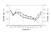
- FIG. 2 is a graph showing changes in the lattice constant of the R 2 Fe 14 B compound.
- Ce 2 lattice constant of a-axis and c-axis of the Fe 14 B compound, from the trend of change is considered to take an intermediate value between the La 2 Fe 14 B compound and Pr 2 Fe 14 B compound, Ce 2
- the lattice constants of the a-axis and c-axis of Fe 14 B deviate from this tendency, and both are depressed.
- Patent Document 1 JP-A-59-46008 (Patent Document 1) and JP-A-59-64733 (Patent Document 2), a magnet having a mixed composition of Nd and Ce, respectively, A magnet with a mixed composition of Tb and Ce is shown.
- the Ce atom originally has one 4f electron, but in the Ce 2 Fe 14 B compound, the 4f electron of the Ce atom is mixed with the conduction electron, and the 4f electron is lost from the Ce atom. ing.
- the loss of 4f electrons in the Ce atom is not limited to the Ce 2 Fe 14 B compound, but is a cerium-transition metal compound (Ce-TM compound) CeCo 5 , Ce 2 Co 17 , Ce 2 Fe 17 , CeTiFe It is a phenomenon commonly seen in 11 etc. In these compounds, a drop in lattice constant similar to that of the Ce 2 Fe 14 B compound in the R 2 Fe 14 B compound described above is observed, and the uniaxial magnetocrystalline anisotropy Ku is also low.
- Ce-TM compound cerium-transition metal compound
- a Ce-TM compound mainly composed of Ce As a permanent magnet material was conducted except for an example in which a CeCo 5 compound having a high crystal magnetic anisotropy of a Co sublattice was put into practical use as a Ce (CoFeCu) 5 magnet.
- a Ce 2 Fe 14 B compound As a candidate material for permanent magnets, a Ce 2 Fe 14 B compound, which is a Ce-TM compound, has not attracted attention.
- a Ce 2 Fe 14 B compound which is a Ce-TM compound of a Ce atom that originally has a potential to give a high uniaxial crystal magnetic anisotropy Ku, recalls 4f electrons to the Ce atom and isolates it, Has recovered its inherent magnetism (magnetic moment and magnetic anisotropy), and this Ce atom isolation can be achieved by replacing part of Ce in the Ce 2 Fe 14 B compound with other elements, specifically , Ca, Sr, and Ba.
- the composition is substituted with one or more alkaline earth metal elements selected from the group consisting of Ca, Sr, and Ba, thereby achieving a structure in which the crystal lattice is expanded.
- Patent Document 9 discloses that an R—Fe—M—B—C—C-based alloy magnet to which Ba, Sr, Ca, or the like is added as M has a reduced boron B content.
- carbon C By adding carbon C, the magnetic temperature characteristics of the grain boundary phase containing carbon C are improved, and further, diffusion of carbon C into the grain boundary phase is promoted by the M addition element, and irreversible demagnetization is reduced.
- carbon C is an essential component
- a Ce— such as a Ce 2 Fe 14 B compound has been conventionally used.
- the TM compound has low magnetic properties, and the specific example of the rare earth element R in this case is only a combination of Nd or Nd and a rare earth element other than Ce, and there is no specific example using Ce.
- the present invention is an RFeB magnet having a so-called Nd 2 Fe 14 B structure phase (2-14-1 phase), and R is a magnet mainly composed of Ce.
- the rare earth permanent magnet of the present invention has a composition containing one or more alkaline earth metal elements selected from the group consisting of Ca, Sr and Ba. It is not certain in what form the alkaline earth metal element of the present invention is contained, but the high magnetic properties of the rare earth permanent magnet of which the main component of the rare earth element of the present invention is Ce.
- a structure in which the crystal lattice is expanded by an alkaline earth metal atom in a part of the Ce site of the 2-14-1 phase of the RFeB magnet mainly composed of Ce, particularly, the Ce site with an alkaline earth metal atom. Is presumed to have a substituted structure.
- the rare earth permanent magnet of the present invention has a Ce 2 Fe 14 B structure phase as a 2-14-1 phase in that the essential magnetic anisotropy of Ce atoms is recovered by such a structure. This is completely different from the RFeB magnet.
- one 4f electron of the Ce atom is isolated, in other words, this electron is called back to the 4f orbit instead of being mixed with the conduction electron. Therefore, it is necessary to exist as localized electrons, by increasing the lattice constant without breaking the basic crystal structure of Ce 2 Fe 14 B, and by widening the space for accommodating Ce atoms in the crystal lattice. Have realized it.
- the rare earth permanent magnet of the present invention contains one or more selected from rare earth elements including Y, Fe, and B, and may contain inevitable impurities.
- Inevitable impurities are elements mixed in, for example, a powder sintering process, and mainly include O (oxygen), C (carbon), N (nitrogen), H (hydrogen), and the like.
- the rare earth permanent magnet of the present invention has a composition excluding inevitable impurities having the following composition formula (1): (R 1-x AE x ) y (Fe 1-a M a ) 100-yz B z (1)
- R is at least one selected from rare earth elements including Y, and at least one light rare earth element selected from the group consisting of Y, La, Ce, Pr, Nd, Pm, Sm, and Eu.
- R is Ce
- AE is one or more alkaline earth metal elements selected from the group consisting of Ca, Sr and Ba
- M is Cu
- Ni , Ti, Mo, Zr, Hf, Ga, Al and Si are one or more elements selected from the group consisting of x, y and z, where 0 ⁇ x ⁇ 0.4 and 10 ⁇ y ⁇ 20, respectively.
- 4 is a positive number that satisfies 4 ⁇ z ⁇ 12
- a is a positive number that satisfies 0 or 0 ⁇ a ⁇ 0.1.
- Nd 2 Fe 14 B structure phase tetragonal Nd 2 Fe 14 B type rare earth intermetallic compound phase
- 2-14-1 phase for example, a crystal phase
- RFeB magnet (2-14-1 phase is the largest.
- the element represented by R contained in the rare earth permanent magnet of the present invention is at least one selected from rare earth elements including Y, and R is composed of Y, La, Ce, Pr, Nd, Pm, Sm and Eu.
- the rare earth permanent magnet of the present invention is LR 2 Fe 14 B (LR is one or more light rare earth elements selected from the group consisting of Y, La, Ce, Pr, Nd, Pm, Sm and Eu, preferably Is partially substituted with one or more alkaline earth metal elements selected from the group consisting of Ca, Sr and Ba.) Phase), and the Curie temperature of this phase is more preferably 500K or more.
- the rare earth element R preferably 60 atom% or more, more preferably 70 atom% or more, still more preferably 95 atom% or more, particularly preferably 100 atom% is Ce.
- the Stevens factor ⁇ J preferably contains 0 or a negative light rare earth element such as La, Pr, Nd, etc.
- the rare earth element R contains Ce, La, More preferably, it comprises one or more rare earth elements selected from the group consisting of Pr and Nd.
- heavy rare earth elements other than light rare earth elements such as Y, La, Ce, Pr, Nd, Pm, Sm and Eu, that is, selected from the group consisting of Gd, Tb, Dy, Ho, Er, Tm, Yb and Lu.
- the content thereof is preferably 20 atomic% or less, preferably 10 atomic% or less, more preferably 5 atomic% or less in the rare earth element represented by R.
- N atoms or C atoms are introduced in the vicinity of R atoms in an interstitial manner, such as R 2 Fe 17 N 3 or RTiFe 11 N. If this method is applied, even in an RFeB magnet, a method of introducing N atoms such as R 2 Fe 14 BN x around the R atoms in an interstitial manner is possible, but such interstitial nitrogen compounds are Decomposes at 1,000 ° C. or lower to become RN x , Fe—Me (Me is an additive metal such as Ti) or the like. Interstitial nitrogen compounds can be mixed with organic resin binders as fine powders, compacted and used as bonded magnets, but when sintered magnets are used, lattice expansion by the method of introducing interstitial types Is not applicable.
- the R atom sites in the crystal lattice are partially substituted with atoms having different atomic radii to stabilize the structure, develop the inherent magnetism of the R atoms, It is considered possible to adjust the interaction with the rare earth atom sublattice other than the RFeB magnet mainly composed of Ce of the present invention.
- the content ratio of the alkaline earth metal element AE (x in the composition formula (1)) can be up to 0.4 with respect to the rare earth element R.
- the content x exceeds 0.4, the structure of the 2-14-1 phase becomes unstable, and the Ce amount decreases, resulting in a significant decrease in uniaxial crystal magnetic anisotropy Ku.
- the content ratio x is less than 0.01, lattice expansion is insufficient, 4f electrons of Ce atoms are not sufficiently recovered, and sufficient uniaxial crystal magnetic anisotropy Ku may not be obtained.
- the content ratio x of the alkaline earth metal element AE is that the recovery of the magnetic anisotropy of the Ce atom and the loss of the magnetic anisotropy caused by the electron orbit of the Ce atom in the structure of the 2-14-1 phase.
- the composition of the rare earth permanent magnet of the present invention is such that at least a part of Ce atoms is 4f of Ce atoms in both cases where R is only Ce and R contains Ce and a rare earth element other than Ce. It is necessary that one electron is recovered in the orbit, one 4f electron of Ce atom is isolated, and the 2-14-1 phase has a uniaxial magnetocrystalline anisotropy Ku.
- 50 atom% or more, particularly 60 atom% or more, particularly 70 atom% or more in the rare earth element R is preferably a Ce atom having an orbital angular momentum of one 4f electron.
- the Fe sublattice in the Ce 2 Fe 14 B compound does not change the value of the uniaxial crystal magnetic anisotropy Ku even when the Ce site is expanded.
- the ratio of the alloy of the corresponding composition to the anisotropic magnetic field Ha is preferably 1.5 times or more, particularly preferably 2 times or more, and particularly preferably 2.5 times or more.
- the rare earth permanent magnet of the present invention may contain an element that substitutes Fe as a main component.
- the substitution element M is an additive element used in an RFeB magnet such as an NdFeB magnet, and can be applied to the rare earth permanent magnet of the present invention, and is not particularly limited. Transition metal elements such as Cu, Ni, Ti, Mo, Zr, and Hf, and typical elements such as Ga, Al, and Si, which are not transition metal elements, and transition metal elements and typical elements can be used to improve coercive force. The combination with is also effective. Therefore, the substitution element M may not be included, but one or more elements selected from the group consisting of Cu, Ni, Ti, Mo, Zr, Hf, Ga, Al, and Si are included as the substitution element M.
- the content ratio of the substitution element M (a in the above composition formula (1)) is a positive number satisfying 0 or 0 ⁇ a ⁇ 0.1, and preferably 0.01 ⁇ a. If it is too high, the saturation magnetization Ms may be remarkably lowered. Therefore, it is preferable that a ⁇ 0.07, particularly a ⁇ 0.05.
- the total composition excluding inevitable impurities is 100, and the content ratio of the rare earth element R and the alkaline earth metal element AE (y in the composition formula (1)) is 10 ⁇ y ⁇ A positive number range satisfying 20. If y ⁇ 10, the Ce-rich phase decreases in the alloy structure of the rare earth permanent magnet, and a magnetic soft phase such as an Fe phase or Fe 3 B phase is generated, resulting in a decrease in sintered body density or coercive force. It is not preferable from the viewpoint. If y> 20, the non-magnetic phase in the Ce-rich phase increases in the alloy structure of the rare earth permanent magnet, and the ratio of the 2-14-1 phase, which is the magnetic phase, decreases.
- the content ratio y of the rare earth element R and the alkaline earth metal element AE is 12 ⁇ y from the balance between the Ce-rich phase contributing to the formation of the high-density sintered body and the 2-14-1 phase contributing to the high magnetic properties. It is preferable that y ⁇ 18, particularly y ⁇ 16.
- the total composition excluding inevitable impurities is 100, and the boron B content ratio (z in the above composition formula (1)) is a positive number in the range satisfying 4 ⁇ z ⁇ 12. is there.
- a magnetic soft phase such as an Fe phase or an R 2 Fe 17 phase is generated in the alloy structure of the rare earth permanent magnet, which is not preferable from the viewpoint of a sintered body density and a reduction in coercive force.
- z> 12 a magnetic soft phase such as an Fe 3 B phase and other nonmagnetic phases are generated, resulting in a decrease in coercive force and a decrease in saturation magnetization.
- the boron B content ratio z is preferably 5 ⁇ z, particularly 6 ⁇ z. , Z ⁇ 10 is preferable.
- the present invention may be a bonded magnet using magnetic powder, but is preferably a sintered magnet.
- a sintered magnet an anisotropic sintered magnet produced mainly by a powder metallurgy method is suitable.
- an anisotropic sintered magnet having an apparent density of 95% or more of the true density can be obtained.
- an alloy fine powder represented by the above composition formula (1) is converted into an alloy composed of a single metal and / or two or more metals, boron and / or Or a step of melting and pulverizing an alloy composed of a metal and boron, Applying a magnetic field in a uniaxial direction to the alloy fine powder and orienting the alloy fine powder in the magnetic field direction;
- a process of compressing and molding oriented alloy fines It can be manufactured by a method including a step of sintering the compacted compact and a step of heat-treating the sintered body.
- R alloys such as rare earth metals R, alloys of R and Fe, alkaline earth metals AE, AE alloys, Fe, Fe alloys, substitution elements M, M A metal, an alloy, or boron selected from the above alloys, boron B, ferroboron, and the like is used as a raw material, and the raw material is weighed so that the constituent elements have a predetermined ratio.
- the raw material with a high vapor pressure is slightly larger in consideration of evaporation during the production process such as during the production of the alloy represented by the composition formula (1), during the pulverization, and during the sintering by the powder metallurgy technique. Can be weighed.
- the weighed raw material is heated to a melting point or higher by resistance heating, high-frequency induction heating, or the like, and is made into an alloy of predetermined constituent elements.
- the melting step is preferably performed in an inert atmosphere such as a rare gas or in vacuum so that the alloy is not oxidized or nitrided.
- the obtained alloy (bulk alloy) is applied to one or a plurality of pulverization methods (for example, multistage pulverization using a jaw crusher, a brown mill, or a jet mill), for example, a fine powder having an average particle diameter of 1 to 20 ⁇ m.
- the pulverization step is preferably performed in an inert atmosphere such as a nitrogen gas atmosphere or a rare gas or in a vacuum so that the alloy is not oxidized.
- a magnetic field is applied to the obtained alloy fine powder in a uniaxial direction to orient the alloy fine powder in the magnetic field direction.
- the C axis of the alloy fine powder is oriented in the magnetic field direction.
- the alloy fine powder is compressed and molded while maintaining this orientation state (preferably while applying a magnetic field).
- the applied magnetic field is preferably higher in direction and strength in both the orientation process and the compression molding process.
- there are physical limitations of the apparatus generally 400 kA / m to 1,200 kA / m. The following.
- the compressed molded body is sintered at a temperature of 800 to 1,200 ° C., preferably in an inert atmosphere such as a nitrogen gas atmosphere or a rare gas, or in a vacuum, depending on the composition.
- an inert atmosphere such as a nitrogen gas atmosphere or a rare gas
- the obtained sintered body is subjected to a temperature suitable for the composition, for example, a temperature of 600 to 800 ° C., preferably in an inert atmosphere such as a nitrogen gas atmosphere or a rare gas, or in a vacuum.
- Heat treatment is performed at
- the sintered magnet manufactured by such a method can be obtained as an anisotropic sintered magnet reflecting the magnetic field orientation in the molding process. Practically, it is possible to perform a process such as cutting into a predetermined shape, and a corrosion-resistant coating such as plating, PVD, or painting depending on the purpose of use.
- a bonded magnet for example, a bulk alloy is obtained by the same method as the above-described sintered magnet manufacturing method, and this is pulverized, for example, coarse powder after Brown mill and fine powder after jet mill And then mixed with an organic resin binder (for example, epoxy resin), and the mixed powder of the alloy fine powder and organic resin binder is oriented in a magnetic field, and then compacted by compacting. Then, the molded body can be heat-cured to form a compression-molded anisotropic bonded magnet.
- an organic resin binder for example, epoxy resin
- alloy fine powder after orienting the alloy fine powder in a magnetic field, compacting is performed to obtain a compact, and the compact is impregnated with a liquid resin composition and heat-cured to obtain a compression-molded anisotropic bonded magnet.
- mixed powder of alloy fine powder and organic resin binder especially thermoplastic resin
- a magnetic field is applied in a state where the organic resin binder is melted, thereby injection molding.
- An anisotropic bonded magnet can also be used.
- the rare earth permanent magnet of the present invention usually contains inevitable impurities.
- This inevitable impurity is an element other than the constituent element of the composition formula (1), and is not particularly limited.
- Inevitable impurities mainly include oxygen, nitrogen, carbon, hydrogen, and the like.
- oxygen O is mainly mixed by oxidation in the alloy crushing process or derived from the raw material, and may be mixed from the raw material.
- Nitrogen N may be mixed by using N 2 gas in the pulverization step, for example, and may be mixed from the raw material.
- Carbon C is also mixed from the melting process and the sintering process and from the raw material.
- hydrogen H when hydrogen H is used in the pulverization process and pulverized, a small amount of hydrogen H may be mixed.
- Other elements may also be included from the raw material.
- the content of inevitable impurities cannot be controlled by setting a specific content, but it is desirable that the content of inevitable impurities not contributing to the magnetic properties of the permanent magnet is as small as possible. Therefore, the content of inevitable impurities is usually preferably 5,000 ppm (mass ratio) or less, particularly 1,000 ppm (mass ratio) or less, and in particular, the oxygen, nitrogen, carbon, and hydrogen content is 3 or less. It is preferably 1,000 ppm (mass ratio) or less, particularly 1,000 ppm (mass ratio) or less.
- boron B which is a constituent element
- boron alone pure boron
- Fe—B alloy ferrroboron
- Al is mixed in the Fe—B alloy at a constant rate because it is reduced by an Al thermit reaction. Therefore, Al may be included as a metal impurity in the raw material, but Al is an element that may be included as the substitution element M in the rare earth permanent magnet of the present invention, and Al contributes to an increase in coercive force. Therefore, a certain amount of Al derived from the raw material is allowed.
- the Ce atom originally has one 4f electron, and the Stevens factor ( ⁇ J: constant that determines the shape of the 4f electron cloud) of the 4f electron is negative, and as shown in FIG. It is a flat electron cloud.
- ⁇ J constant that determines the shape of the 4f electron cloud
- a Ce atom having one 4f electron has a very flat 4f electron cloud, and therefore, a light atom other than Ce is obtained by the 2-14-1 phase of the Ce atom having one 4f electron.
- a higher uniaxial magnetocrystalline anisotropy Ku can be obtained than the 2-14-1 phase of rare earth elements or heavy rare earth elements.
- the rare earth permanent magnet of the present invention containing the 2-14-1 phase containing Ce atoms having one 4f electron has high magnetic properties even if heavy rare earth elements are not substituted to increase the coercive force. have. Further, since Ce atoms are light rare earth elements, the magnetic moments of Ce and Fe are parallel, and there is almost no decrease in saturation magnetization Ms. Furthermore, Ce has the largest number of Clarkes among the rare earth elements and is abundant among the rare earth elements, so that it is least likely to cause resource problems.
- Hc coercive force
- Examples 1 to 6, Comparative Examples 1 to 3 Ce and La, rare earth element R, alkaline earth metal AE (Ca, Sr or Ba), Fe, substitution element M (Cu or Ga) and boron B (both having a purity of 99% by mass or more) are evaporated during melting. Considering this, the rare earth element R and the alkaline earth metal AE were weighed by 0.5 atomic% more than the predetermined composition. The atomic ratio of Ce and La was 85:15. Next, after filling the weighed raw materials into a crucible of a high-frequency vacuum melting furnace, the inside of the furnace was depressurized to 1 ⁇ 10 ⁇ 3 Pa, and a high-frequency alternating current was applied to the high-frequency coil to raise the temperature.
- the obtained alloy was pulverized.
- Coarse pulverization was performed by pulverizing to 200 mesh under with a jaw crusher and a brown mill, and further pulverizing to an average particle size of 4 ⁇ m with a jet mill using N 2 airflow.
- the obtained alloy fine powder has a particle size distribution, but is generally in the range of 1 ⁇ m to 10 ⁇ m. Since the fine pulverization is performed in an N 2 gas stream, the oxidation of the alloy fine powder is suppressed, and the oxygen content in the alloy is approximately 0.3% by mass or less.
- Composition analysis was performed by ICP (inductively coupled plasma emission spectrometry), and each value of x, y, z and a in the composition formula (1) was determined. These values obtained from the composition analysis are shown in Table 4.
- Each alloy fine powder was subjected to XRD (X-ray diffraction measurement).
- XRD X-ray diffraction measurement
- Comparative Examples 1 to 3 in addition to the peak that can be indexed as the 2-14-1 phase, there are ⁇ -Fe phases that are not alloyed and peaks that can be indexed as the Ce 2 Fe 17 phase. Phases other than the 14-1 phase were included.
- the alloy fine powder is filled into a die mold having square filling holes, a static magnetic field of 800 kA / m is applied to the alloy fine powder, the C axis of the alloy fine powder is oriented in the magnetic field direction, and the orientation state is maintained.
- compacting was performed at a pressure of 100 kg / cm 2 (about 9.8 MPa) to produce a compact.
- the obtained compact was heated and heated with a VSM (vibrating sample magnetometer), and the temperature at which the magnetization of the alloy fine powder disappeared (Curie temperature Tc) was measured.
- the phases other than the ⁇ -Fe phase and the Ce 2 Fe 17 phase in the thermomagnetic curve were regarded as the 2-14-1 phase, and this was set as the Curie temperature of the 2-14-1 phase.
- a liquid adhesive is soaked in a molded body obtained by the same method, and the adhesive is solidified at room temperature to produce a bonded magnet.
- the magnetic field orientation direction and the perpendicular magnetization curve of the bonded magnet are represented by VSM.
- the saturation magnetization Ms and the anisotropic magnetic field (theoretical maximum coercive force) Ha were determined.
- the intersection of both magnetization curves can be simply regarded as the anisotropic magnetic field Ha.
- the saturation magnetization Ms in this case is not only the value of the 2-14-1 phase because the measured saturation magnetization Ms is superposed with the magnetization of the ⁇ -Fe phase or the like.
- the amount of unalloyed Fe ( ⁇ -Fe phase) was large, and the anisotropic magnetic field Ha could not be accurately evaluated.
- Comparative Example 3 since the ⁇ -Fe phase was relatively small, the amount was estimated from the thermomagnetic curve, and the amount was subtracted to obtain the value of the anisotropic magnetic field Ha of the 2-14-1 phase.
- the anisotropic magnetic field Ha of the example is greatly improved as compared with the anisotropic magnetic field Ha of the comparative example, and in the rare earth permanent magnet of the present invention, Ce atoms recover the magnetic anisotropy. It is presumed that On the other hand, it is presumed that the relative increase in the saturation magnetization Ms and the Curie temperature Tc is mainly due to the effect of increasing the magnetic moment of Fe due to the increase in the Fe-Fe distance.
- the rare earth element R is Ce and Pr
- the substitution element M is Si, Cu, Ga, or Ni
- the atomic ratio of Ce and Pr is 85:15
- Fe—B alloy (ferroboron) is used without boron B.
- An alloy fine powder and a compact were produced in the same manner as in Example 1 except that was used.
- Example 8 the composition and physical properties of the alloy fine powder, and the physical properties and magnetic properties of the compact or bonded magnet were evaluated. The results are shown in Table 5.
- Al was contained as the substitution element M in any alloy fine powder by using the Fe-B alloy.
- the atomic ratio between Al and Si is 2: 1
- the atomic ratio between Al and Cu in Example 9 is 2: 2
- the atomic ratio between Al and Ga in Example 10 is 1: 1.
- the atomic ratio of Ca and Sr is 1: 3
- the atomic ratio of Al and Ni is 3: 1
- the atomic ratio of Ba and Sr in Example 12 is 3: 2 (x in the above composition formula (1)).
- the rare earth element R is Ce and Nd
- the substitution element M is Si, Cu, Ga or Ni
- the atomic ratio of Ce and Nd is 95: 5
- Fe—B alloy (ferroboron) without boron B is used.
- An alloy fine powder was produced in the same manner as in Example 1 except that was used.
- the alloy fine powder is filled into the die mold, and a static magnetic field of 800 kA / m is applied to the alloy fine powder to orient the fine powder C axis in the magnetic field direction, and the die mold is formed by the upper and lower punches while maintaining the orientation state.
- the filled alloy fine powder was compression molded at a pressure of 100 kg / cm 2 (about 9.8 MPa) to produce a molded body.
- the obtained molded body is put into a sintering furnace, and the pressure is reduced to a level of 10 ⁇ 5 Pa.
- Ar gas is introduced and sintered in an Ar gas atmosphere of 10 Pa at a temperature of about 1,100 ° C.
- the sintered magnet was obtained by heat treatment (aging treatment) at about 1,050 to 1,150 ° C. in a heat treatment furnace. The obtained sintered magnet was sintered and densified to an apparent density of 95% or more of the true density.
- the composition and physical properties of the alloy fine powder were evaluated in the same manner as in Example 1. The results are shown in Table 6.
- Al was contained as the substitution element M in any alloy fine powder by using the Fe-B alloy.
- the atomic ratio of Al and Si in Example 14 is 4: 1
- the atomic ratio of Al and Cu in Example 15 is 2: 3
- the atomic ratio of Al and Ga in Example 16 is 1: 1.
- the atomic ratio of Ca and Sr was 2: 1 (in the composition formula (1) x, Ca was 0.134, Sr was 0.066), and the atomic ratio of Al and Ni was 5: 1. It was.
- the oxygen content in the alloy was generally 0.3% by mass or less.
- the Curie temperature Tc was evaluated in the same manner as in Example 1 except that a sintered magnet was used instead of the compact, and the hysteresis curve was measured with a BH tracer using the sintered magnet. The magnetic force Hc was evaluated. The results are shown in Table 6.
Abstract
L'invention concerne un aimant permanent aux terres rares qui comprend Fe, B et un ou plusieurs éléments choisis parmi les éléments des terres rares y compris Y, la structure de l'aimant aux terres rares, à l'exception d'impuretés inévitables, étant exprimée par la formule (R1-xAEx)y(Fe1-aMa)100-y-zBz (dans laquelle R représente un ou plusieurs éléments choisis parmi les éléments des terres rares y compris Y, et comprend au moins 70 % atomique d'un ou plusieurs éléments choisis dans le groupe constitué par Y, La, Ce, Pr, Nd, Pm, Sm et Eu, au moins 50 % atomique de R étant Ce ; AE représente un ou plusieurs éléments choisis dans le groupe constitué par Ca, Sr et Ba ; M représente un ou plusieurs éléments choisis dans le groupe constitué par Cu, Ni, Ti, Mo, Zr, Hf, Ga, Al et Si ; x, y et z sont tous des nombres positifs satisfaisant les conditions 0 < x ≤ 0,4, 10 ≤ y ≤ 20, et 4 ≤ z ≤ 12 ; et a vaut 0 ou un nombre positif satisfaisant la condition 0 < a ≤ 0,1), ce qui permet d'obtenir un aimant permanent aux terres rares dans lequel la teneur en éléments lourds des terres rares est réduite autant que possible, l'aimant permanent aux terres rares est suffisant pour une utilisation pratique, et le champ coercitif Hc et l'aimantation à saturation Ms sont équilibrés avec des caractéristiques à haute température.
Applications Claiming Priority (2)
| Application Number | Priority Date | Filing Date | Title |
|---|---|---|---|
| JP2016-092301 | 2016-05-02 | ||
| JP2016092301 | 2016-05-02 |
Publications (1)
| Publication Number | Publication Date |
|---|---|
| WO2017191790A1 true WO2017191790A1 (fr) | 2017-11-09 |
Family
ID=60203572
Family Applications (1)
| Application Number | Title | Priority Date | Filing Date |
|---|---|---|---|
| PCT/JP2017/016506 WO2017191790A1 (fr) | 2016-05-02 | 2017-04-26 | Aimant permanent aux terres rares et son procédé de fabrication |
Country Status (1)
| Country | Link |
|---|---|
| WO (1) | WO2017191790A1 (fr) |
Cited By (1)
| Publication number | Priority date | Publication date | Assignee | Title |
|---|---|---|---|---|
| CN112447351A (zh) * | 2019-08-29 | 2021-03-05 | 丰田自动车株式会社 | 稀土磁体 |
Citations (2)
| Publication number | Priority date | Publication date | Assignee | Title |
|---|---|---|---|---|
| JPS5495917A (en) * | 1978-01-13 | 1979-07-28 | Tdk Corp | Permanent magnet material |
| JPS6180805A (ja) * | 1984-09-27 | 1986-04-24 | Daido Steel Co Ltd | 永久磁石材料 |
-
2017
- 2017-04-26 WO PCT/JP2017/016506 patent/WO2017191790A1/fr active Application Filing
Patent Citations (2)
| Publication number | Priority date | Publication date | Assignee | Title |
|---|---|---|---|---|
| JPS5495917A (en) * | 1978-01-13 | 1979-07-28 | Tdk Corp | Permanent magnet material |
| JPS6180805A (ja) * | 1984-09-27 | 1986-04-24 | Daido Steel Co Ltd | 永久磁石材料 |
Cited By (2)
| Publication number | Priority date | Publication date | Assignee | Title |
|---|---|---|---|---|
| CN112447351A (zh) * | 2019-08-29 | 2021-03-05 | 丰田自动车株式会社 | 稀土磁体 |
| CN112447351B (zh) * | 2019-08-29 | 2024-02-23 | 丰田自动车株式会社 | 稀土磁体 |
Similar Documents
| Publication | Publication Date | Title |
|---|---|---|
| JP4830024B2 (ja) | 磁石用複合磁性材料、及びその製造方法 | |
| JP4805998B2 (ja) | 永久磁石とそれを用いた永久磁石モータおよび発電機 | |
| JP5218869B2 (ja) | 希土類−鉄−窒素系合金材、希土類−鉄−窒素系合金材の製造方法、希土類−鉄系合金材、及び希土類−鉄系合金材の製造方法 | |
| JP6094612B2 (ja) | R−t−b系焼結磁石の製造方法 | |
| JP2001093713A (ja) | 多元系希土類−鉄格子浸入型永久磁石材料、およびそれからなる永久磁石、ならびにそれらの製造方法 | |
| JP2001189206A (ja) | 永久磁石 | |
| WO2015159612A1 (fr) | Aimant permanent en terres rares | |
| JP4700578B2 (ja) | 高抵抗希土類系永久磁石の製造方法 | |
| JP6860808B2 (ja) | R−t−b系焼結磁石の製造方法 | |
| JP4900085B2 (ja) | 希土類磁石の製造方法 | |
| JP6569408B2 (ja) | 希土類永久磁石 | |
| JP6511844B2 (ja) | R−t−b系焼結磁石 | |
| WO2017191790A1 (fr) | Aimant permanent aux terres rares et son procédé de fabrication | |
| EP3276639A1 (fr) | Matériau d'aimant, aimant permanent, moteur et génératrice | |
| JP6623998B2 (ja) | R−t−b系焼結磁石の製造方法 | |
| JPWO2019065481A1 (ja) | R−t−b系焼結磁石の製造方法 | |
| WO2018101409A1 (fr) | Aimant fritté à base de terres rares | |
| KR102399418B1 (ko) | 소결 자석 제조 방법 및 이에 따라 제조된 소결 자석 | |
| JP4534553B2 (ja) | R−t−b系焼結磁石及びその製造方法 | |
| JPH045739B2 (fr) | ||
| JPH03170643A (ja) | 永久磁石用合金 | |
| JPH044386B2 (fr) | ||
| JP2019169560A (ja) | R−t−b系焼結磁石の製造方法 | |
| WO2022202197A1 (fr) | Poudre magnétique anisotrope à base de terres rares et procédé pour sa production | |
| JPH044385B2 (fr) |
Legal Events
| Date | Code | Title | Description |
|---|---|---|---|
| NENP | Non-entry into the national phase |
Ref country code: DE |
|
| 121 | Ep: the epo has been informed by wipo that ep was designated in this application |
Ref document number: 17792723 Country of ref document: EP Kind code of ref document: A1 |
|
| 122 | Ep: pct application non-entry in european phase |
Ref document number: 17792723 Country of ref document: EP Kind code of ref document: A1 |
|
| NENP | Non-entry into the national phase |
Ref country code: JP |