WO2017188247A1 - 表示制御装置 - Google Patents
表示制御装置 Download PDFInfo
- Publication number
- WO2017188247A1 WO2017188247A1 PCT/JP2017/016367 JP2017016367W WO2017188247A1 WO 2017188247 A1 WO2017188247 A1 WO 2017188247A1 JP 2017016367 W JP2017016367 W JP 2017016367W WO 2017188247 A1 WO2017188247 A1 WO 2017188247A1
- Authority
- WO
- WIPO (PCT)
- Prior art keywords
- image
- obstacle
- vehicle
- display control
- display
- Prior art date
- Legal status (The legal status is an assumption and is not a legal conclusion. Google has not performed a legal analysis and makes no representation as to the accuracy of the status listed.)
- Ceased
Links
Images






Classifications
-
- H—ELECTRICITY
- H04—ELECTRIC COMMUNICATION TECHNIQUE
- H04N—PICTORIAL COMMUNICATION, e.g. TELEVISION
- H04N5/00—Details of television systems
- H04N5/44—Receiver circuitry for the reception of television signals according to analogue transmission standards
- H04N5/445—Receiver circuitry for the reception of television signals according to analogue transmission standards for displaying additional information
- H04N5/44504—Circuit details of the additional information generator, e.g. details of the character or graphics signal generator, overlay mixing circuits
-
- B—PERFORMING OPERATIONS; TRANSPORTING
- B60—VEHICLES IN GENERAL
- B60R—VEHICLES, VEHICLE FITTINGS, OR VEHICLE PARTS, NOT OTHERWISE PROVIDED FOR
- B60R1/00—Optical viewing arrangements; Real-time viewing arrangements for drivers or passengers using optical image capturing systems, e.g. cameras or video systems specially adapted for use in or on vehicles
- B60R1/20—Real-time viewing arrangements for drivers or passengers using optical image capturing systems, e.g. cameras or video systems specially adapted for use in or on vehicles
- B60R1/22—Real-time viewing arrangements for drivers or passengers using optical image capturing systems, e.g. cameras or video systems specially adapted for use in or on vehicles for viewing an area outside the vehicle, e.g. the exterior of the vehicle
- B60R1/23—Real-time viewing arrangements for drivers or passengers using optical image capturing systems, e.g. cameras or video systems specially adapted for use in or on vehicles for viewing an area outside the vehicle, e.g. the exterior of the vehicle with a predetermined field of view
- B60R1/27—Real-time viewing arrangements for drivers or passengers using optical image capturing systems, e.g. cameras or video systems specially adapted for use in or on vehicles for viewing an area outside the vehicle, e.g. the exterior of the vehicle with a predetermined field of view providing all-round vision, e.g. using omnidirectional cameras
-
- G—PHYSICS
- G06—COMPUTING OR CALCULATING; COUNTING
- G06T—IMAGE DATA PROCESSING OR GENERATION, IN GENERAL
- G06T1/00—General purpose image data processing
-
- G—PHYSICS
- G06—COMPUTING OR CALCULATING; COUNTING
- G06T—IMAGE DATA PROCESSING OR GENERATION, IN GENERAL
- G06T7/00—Image analysis
- G06T7/10—Segmentation; Edge detection
- G06T7/13—Edge detection
-
- G—PHYSICS
- G06—COMPUTING OR CALCULATING; COUNTING
- G06V—IMAGE OR VIDEO RECOGNITION OR UNDERSTANDING
- G06V20/00—Scenes; Scene-specific elements
- G06V20/50—Context or environment of the image
- G06V20/56—Context or environment of the image exterior to a vehicle by using sensors mounted on the vehicle
- G06V20/58—Recognition of moving objects or obstacles, e.g. vehicles or pedestrians; Recognition of traffic objects, e.g. traffic signs, traffic lights or roads
-
- H—ELECTRICITY
- H04—ELECTRIC COMMUNICATION TECHNIQUE
- H04N—PICTORIAL COMMUNICATION, e.g. TELEVISION
- H04N5/00—Details of television systems
- H04N5/222—Studio circuitry; Studio devices; Studio equipment
- H04N5/262—Studio circuits, e.g. for mixing, switching-over, change of character of image, other special effects ; Cameras specially adapted for the electronic generation of special effects
- H04N5/2628—Alteration of picture size, shape, position or orientation, e.g. zooming, rotation, rolling, perspective, translation
-
- H—ELECTRICITY
- H04—ELECTRIC COMMUNICATION TECHNIQUE
- H04N—PICTORIAL COMMUNICATION, e.g. TELEVISION
- H04N5/00—Details of television systems
- H04N5/222—Studio circuitry; Studio devices; Studio equipment
- H04N5/262—Studio circuits, e.g. for mixing, switching-over, change of character of image, other special effects ; Cameras specially adapted for the electronic generation of special effects
- H04N5/272—Means for inserting a foreground image in a background image, i.e. inlay, outlay
-
- H—ELECTRICITY
- H04—ELECTRIC COMMUNICATION TECHNIQUE
- H04N—PICTORIAL COMMUNICATION, e.g. TELEVISION
- H04N7/00—Television systems
- H04N7/18—Closed-circuit television [CCTV] systems, i.e. systems in which the video signal is not broadcast
-
- B—PERFORMING OPERATIONS; TRANSPORTING
- B60—VEHICLES IN GENERAL
- B60R—VEHICLES, VEHICLE FITTINGS, OR VEHICLE PARTS, NOT OTHERWISE PROVIDED FOR
- B60R2300/00—Details of viewing arrangements using cameras and displays, specially adapted for use in a vehicle
- B60R2300/30—Details of viewing arrangements using cameras and displays, specially adapted for use in a vehicle characterised by the type of image processing
- B60R2300/304—Details of viewing arrangements using cameras and displays, specially adapted for use in a vehicle characterised by the type of image processing using merged images, e.g. merging camera image with stored images
-
- B—PERFORMING OPERATIONS; TRANSPORTING
- B60—VEHICLES IN GENERAL
- B60R—VEHICLES, VEHICLE FITTINGS, OR VEHICLE PARTS, NOT OTHERWISE PROVIDED FOR
- B60R2300/00—Details of viewing arrangements using cameras and displays, specially adapted for use in a vehicle
- B60R2300/30—Details of viewing arrangements using cameras and displays, specially adapted for use in a vehicle characterised by the type of image processing
- B60R2300/304—Details of viewing arrangements using cameras and displays, specially adapted for use in a vehicle characterised by the type of image processing using merged images, e.g. merging camera image with stored images
- B60R2300/305—Details of viewing arrangements using cameras and displays, specially adapted for use in a vehicle characterised by the type of image processing using merged images, e.g. merging camera image with stored images merging camera image with lines or icons
-
- B—PERFORMING OPERATIONS; TRANSPORTING
- B60—VEHICLES IN GENERAL
- B60R—VEHICLES, VEHICLE FITTINGS, OR VEHICLE PARTS, NOT OTHERWISE PROVIDED FOR
- B60R2300/00—Details of viewing arrangements using cameras and displays, specially adapted for use in a vehicle
- B60R2300/30—Details of viewing arrangements using cameras and displays, specially adapted for use in a vehicle characterised by the type of image processing
- B60R2300/307—Details of viewing arrangements using cameras and displays, specially adapted for use in a vehicle characterised by the type of image processing virtually distinguishing relevant parts of a scene from the background of the scene
-
- B—PERFORMING OPERATIONS; TRANSPORTING
- B60—VEHICLES IN GENERAL
- B60R—VEHICLES, VEHICLE FITTINGS, OR VEHICLE PARTS, NOT OTHERWISE PROVIDED FOR
- B60R2300/00—Details of viewing arrangements using cameras and displays, specially adapted for use in a vehicle
- B60R2300/60—Details of viewing arrangements using cameras and displays, specially adapted for use in a vehicle characterised by monitoring and displaying vehicle exterior scenes from a transformed perspective
- B60R2300/607—Details of viewing arrangements using cameras and displays, specially adapted for use in a vehicle characterised by monitoring and displaying vehicle exterior scenes from a transformed perspective from a bird's eye viewpoint
-
- B—PERFORMING OPERATIONS; TRANSPORTING
- B60—VEHICLES IN GENERAL
- B60R—VEHICLES, VEHICLE FITTINGS, OR VEHICLE PARTS, NOT OTHERWISE PROVIDED FOR
- B60R2300/00—Details of viewing arrangements using cameras and displays, specially adapted for use in a vehicle
- B60R2300/80—Details of viewing arrangements using cameras and displays, specially adapted for use in a vehicle characterised by the intended use of the viewing arrangement
- B60R2300/8093—Details of viewing arrangements using cameras and displays, specially adapted for use in a vehicle characterised by the intended use of the viewing arrangement for obstacle warning
-
- G—PHYSICS
- G06—COMPUTING OR CALCULATING; COUNTING
- G06T—IMAGE DATA PROCESSING OR GENERATION, IN GENERAL
- G06T2207/00—Indexing scheme for image analysis or image enhancement
- G06T2207/30—Subject of image; Context of image processing
- G06T2207/30248—Vehicle exterior or interior
- G06T2207/30252—Vehicle exterior; Vicinity of vehicle
- G06T2207/30261—Obstacle
-
- G—PHYSICS
- G06—COMPUTING OR CALCULATING; COUNTING
- G06V—IMAGE OR VIDEO RECOGNITION OR UNDERSTANDING
- G06V2201/00—Indexing scheme relating to image or video recognition or understanding
- G06V2201/08—Detecting or categorising vehicles
Definitions
- the present disclosure relates to a display control device that displays an image photographed by a camera mounted on a vehicle on a display device provided in the vehicle.
- Patent Document 1 discloses a technique for displaying an image of a rear part of a vehicle on a display device and displaying a symbol indicating the direction and distance of an obstacle detected by a back sonar.
- the driver can know the approximate direction of the obstacle and the distance to the obstacle based on the position and color of the symbol displayed together with the photographed image.
- information such as the position and color of the pattern alone is not sufficient to grasp the specific properties such as what shape the obstacle is facing. A certain problem was found.
- a display control device displays an image created based on a video in which a predetermined range around a vehicle is captured by a camera mounted on the vehicle on a display device provided in the vehicle. It is configured to let you.
- the display control device includes an image acquisition unit, an obstacle specifying unit, and a control unit.
- symbol in the parenthesis described in the claim shows the correspondence with the specific means as described in embodiment mentioned later as one aspect, Comprising: The technical scope of this indication is limited is not.
- the image acquisition unit is configured to acquire a peripheral image that is an image based on a video taken by a camera.
- the peripheral image is an image that directly represents a video captured by the camera, or an image obtained by coordinate-converting a video captured by the camera into an image from another viewpoint (for example, a bird's-eye view image).
- the obstacle specifying unit specifies the shape of the obstacle including at least an inclination in a road surface direction of a portion where the obstacle faces the vehicle with respect to the obstacle specified from the range shown in the peripheral image acquired by the image acquisition unit. It is configured.
- the control unit creates a superimposed image in which a sign image created as a symbol indicating the obstacle is superimposed on a position corresponding to the obstacle on the peripheral image,
- the generated superimposed image is configured to be displayed on the display device.
- the control unit is configured to make the property of the sign image variable according to the inclination of the obstacle specified by the obstacle specifying unit.
- the property of the sign image that is a symbol indicating the obstacle can be freely changed according to the shape including at least the inclination of the obstacle.
- operator of a vehicle can grasp
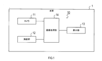
- FIG. 1 is a block diagram illustrating a schematic configuration of an in-vehicle display system.
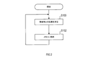
- FIG. 2 is a flowchart showing the procedure of the distance measurement process.
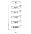
- FIG. 3 is a flowchart showing the procedure of the obstacle display process.
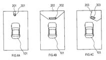
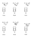
- FIG. 4A is a diagram illustrating a display example of a superimposed image.
- FIG. 4B is a diagram illustrating a display example of a superimposed image.
- FIG. 4C is a diagram illustrating a display example of a superimposed image.
- FIG. 5A is a diagram illustrating a time-series transition of the superimposed image.
- FIG. 5B is a diagram illustrating time-series transition of the superimposed image.
- FIG. 5C is a diagram illustrating a time-series transition of the superimposed image.
- FIG. 6A is a diagram illustrating a variant of the marked image.
- FIG. 6B is a diagram illustrating a variation of the sign image.
- FIG. 6C is a diagram illustrating a variation of the sign image.
- FIG. 6D is a diagram illustrating a variant of the sign image.
- FIG. 6E is a diagram illustrating a variation of the sign image.
- FIG. 6F is a diagram illustrating a variation of the sign image.
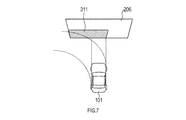
- FIG. 7 is a diagram illustrating a display example of a superimposed image.
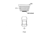
- FIG. 8 is a diagram illustrating a display example of a superimposed image.
- FIG. 7 is a diagram illustrating a display example of a superimposed image.
- FIG. 9 is a diagram illustrating a display example of a superimposed image.
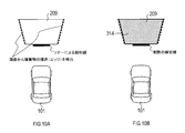
- FIG. 10A is a diagram illustrating a boundary of a detected obstacle.
- FIG. 10B is a diagram illustrating a display example of a superimposed image.
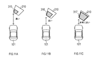
- FIG. 11A is a diagram illustrating a display example of a superimposed image at a long distance.
- FIG. 11B is a diagram illustrating a display example of a superimposed image at a short distance.
- FIG. 11C is a diagram illustrating a display example of a superimposed image at a close distance.
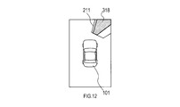
- FIG. 12 is a diagram illustrating a display example of a superimposed image.
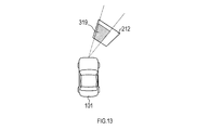
- FIG. 13 is a diagram illustrating a display example of a superimposed image.
- FIG. 14A is a diagram illustrating a display example of a superimposed image.
- FIG. 14B is a diagram illustrating a display example of a superimposed image.
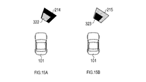
- FIG. 15A is a diagram illustrating a display example of a superimposed image.
- FIG. 15B is a diagram illustrating a display example of a superimposed image.
- FIG. 16 is a diagram illustrating a display example of a superimposed image.
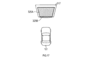
- FIG. 17 is a diagram illustrating a display example of a superimposed image.
- FIG. 18A is a diagram illustrating a display example of a superimposed image at a long distance.
- FIG. 18B is a diagram illustrating a display example of a superimposed image at a short distance.
- FIG. 18C is a diagram illustrating a display example of a superimposed image at a close distance.
- FIG. 19A is a diagram in which an image of the host vehicle is arranged on an original image including surrounding vehicles.
- FIG. 19B is a diagram illustrating a boundary line of a surrounding vehicle that is actually detected.
- FIG. 19C is a diagram in which icons representing vehicles are arranged in accordance with the detection lines.
- FIG. 19D is a diagram in which an icon representing a vehicle is superimposed on an original image of surrounding vehicles.
- FIG. 19E is a diagram in which a transparent icon representing a vehicle is superimposed on an original image of surrounding vehicles.
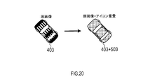
- FIG. 20 is a diagram in which an icon representing a vehicle is superimposed on an original image of surrounding vehicles.
- the in-vehicle display system 10 is a system that supports driving by displaying an image that is mounted on the vehicle 1 and created based on video captured by a camera. As illustrated in FIG. 1, the in-vehicle display system 10 includes an image processing unit 14, a camera 11, a distance measuring unit 12, and a display unit 13 connected to the image processing unit 14.
- the camera 11 is an imaging device installed toward the periphery of the vehicle 1 such as the front, side, and rear.
- the camera 11 is configured to image a peripheral region of the vehicle 1 and output data of an image representing the captured image (hereinafter also referred to as a captured image) to the image processing unit 14.
- the distance measuring unit 12 scans a range photographed by the camera 11, so that obstacles (for example, other vehicles, pedestrians, building walls and pillars) existing in the scanned range, the vehicle 1, And a sensor configured to acquire information representing the direction of the obstacle and the direction viewed from the vehicle 1.
- the distance measuring unit 12 is embodied by, for example, an ultrasonic sonar, a millimeter wave radar, a laser radar, a stereo camera, a monocular camera, a peripheral monitoring camera, or the like. From the measurement result obtained by the distance measuring unit 12, the position of the obstacle, the shape of the boundary, the inclination of the surface, and the approximate width can be recognized.
- the display unit 13 is a display configured to display image information supplied from the image processing unit 14.
- the display unit 13 is provided in a place such as an instrument panel of the vehicle 1 that is easily visible from the driver of the vehicle 1.
- the image processing unit 14 is an information processing apparatus mainly configured with a CPU, a RAM, a ROM, a semiconductor memory such as a flash memory (not shown), an input / output interface, and the like.
- the image processing unit 14 is realized by, for example, a microcontroller or the like in which functions as a computer system are integrated.
- the function of the image processing unit 14 is realized by the CPU executing a program stored in a non-transitional physical storage medium such as a ROM or a semiconductor memory.
- the number of microcontrollers constituting the image processing unit 14 may be one or more.
- the method for realizing the functions of the image processing unit 14 is not limited to software, and some or all of the elements may be realized using hardware in which a logic circuit, an analog circuit, or the like is combined.
- the image processing unit 14 executes distance measurement processing and obstacle display processing according to the above-described program. Details of these processes will be described later. [Description of distance measurement processing] The procedure of the distance measurement process executed by the image processing unit 14 will be described with reference to the flowchart of FIG. This distance measurement process is repeatedly executed every predetermined control period while the in-vehicle display system 10 is in operation.
- the image processing unit 14 uses the distance measuring unit 12 to measure the distance to the obstacle existing around the vehicle 1 and acquires position information regarding the obstacle. Specifically, the image processing unit 14 continuously scans the periphery of the vehicle 1 with detection waves such as radar and sonar constituting the distance measuring unit 12 and receives reflected waves from obstacles, thereby scanning. Position information representing the distribution of the distances of obstacles existing in the specified range is acquired. Alternatively, position information representing the distribution of the distance to the obstacle may be acquired by a known image recognition technique that recognizes the distance to the object from an image captured by a stereo camera, a monocular camera, a peripheral monitoring camera, or the like.
- the image processing unit 14 stores the position information acquired in S100, that is, information indicating the distribution of the distance between the vehicle 1 and the obstacle in the memory in the image processing unit 14. After S102, the image processing unit 14 returns the process to S100.
- the image processing unit 14 acquires the latest captured image for one frame from the camera 11.
- the image processing unit 14 converts the coordinates of the pixels constituting the captured image acquired in S200 using a known bird's-eye conversion process so that the captured image of the camera 11 is located above the vehicle 1. The image is converted into a bird's-eye view image simulating the state seen from the set viewpoint.
- the image processing unit 14 reads the latest position information acquired in the above-described distance measurement process (see FIG. 2) from the memory.
- the image processing unit 14 designates the obstacle present on the bird's-eye image according to the position information read in S204 and the shape of the obstacle shown in the bird's-eye image created in S202.
- a sign image is created. Specific properties of the sign image created here will be described later.
- the image processing unit 14 creates a superimposed image in which the sign image created in S206 is superimposed at a position corresponding to the obstacle reflected on the bird's-eye image created in S202, and the created superimposed image is displayed. It is displayed on the display unit 13.
- the image processing unit 14 superimposes the obstacle image on the obstacle image according to the shape, inclination, position, color, and the like of the obstacle identified in the image captured by the camera 11 and the distance measuring unit 12.
- the superimposed image is created by changing the properties of.
- the property of the sign image here is, for example, the shape, size, inclination, blinking, color, density, transparency, etc. of the symbol.
- FIGS. 1-10 a specific application example of the sign image superimposed on the obstacle image will be described with reference to FIGS.
- FIG. 4A, 4B, and 4C are examples of superimposed images displayed on the display unit 13.
- a vehicle image 101 that is a virtual image representing the appearance of the vehicle 1 (that is, the host vehicle) is arranged.
- the vehicle image 101 is drawn by the image processing unit 14 when an image captured by the camera 11 is converted to a bird's eye view.
- a sign image that is a symbol indicating an obstacle reflected in the bird's-eye view image is drawn by the image processing unit 14.
- the image processing unit 14 creates a sign image 301 composed of a plate-like symbol having a width approximately equal to the width of the obstacle image 201. Then, the image processing unit 14 creates a superimposed image by superimposing the indication image 301 in accordance with the position of the obstacle image 201 on the bird's-eye view image.
- the image processing unit 14 creates a sign image 302 composed of a plate-like symbol having a width wider than that of the case of FIG. 4A according to the width of the obstacle being reflected. Then, the image processing unit 14 creates a superimposed image by superimposing the indication image 302 in accordance with the position of the obstacle image 202 on the bird's-eye view image.
- the image processing unit 14 creates a sign image 303 composed of symbols whose plate-like surfaces are inclined in accordance with the inclination of the obstacle image 203 with respect to the front direction of the vehicle image 101. Then, the image processing unit 14 creates a superimposed image by superimposing the indication image 303 in accordance with the position of the obstacle image 203 on the bird's-eye view image.
- the image processing unit 14 changes the direction of the sign image formed of a plate-like pattern according to the inclination in the road surface direction of the portion where the obstacles 201, 202, and 203 face the vehicle 1. It is configured to be variable. Specifically, the image processing unit 14 determines that the obstacles 201, 202, 203 are connected to the vehicle 1 based on the boundary shape of the obstacles 201, 202, 203 represented by the position information acquired by the distance measuring unit 12. Recognize the slope in the road surface direction of the facing part.
- the image processing unit 14 creates sign images 301, 302, and 303 that are configured with geometric symbols having the same inclination as that of the obstacles 201, 202, and 203 in the bird's-eye image coordinate system.
- the image is superimposed on the images of the obstacles 201, 202, and 203.
- the image processing unit 14 may be configured to periodically blink a sign image displayed to be superimposed on an obstacle image. Moreover, as illustrated in FIGS. 5A, 5B, and 5C, the length of the cycle of blinking the indication image 304 may be changed according to the distance between the vehicle 1 and the obstacle 204. By doing so, the driver can accurately grasp the distance to the obstacle.
- the example of FIG. 5A is a time series representing the temporal transition of the superimposed image displayed by the image processing unit 14 in a situation where the distance between the vehicle 1 and the obstacle is relatively far.
- the image processing unit 14 displays a superimposed image that blinks the sign image 304 superimposed on the obstacle image 204 at a relatively long period.
- the case of FIG. 5B is a time series representing the temporal transition of the superimposed image displayed by the image processing unit 14 in a situation where the distance between the vehicle 1 and the obstacle is relatively short (that is, closer to the case of FIG. 5A). is there.
- the image processing unit 14 displays a superimposed image that blinks the indication image 304 superimposed on the obstacle image 204 at a relatively shorter cycle than the case of FIG. 5A.
- the case of FIG. 5C is a time series representing the temporal transition of the superimposed image displayed by the image processing unit 14 in a situation where the distance between the vehicle 1 and the obstacle is very close (that is, closer to the case of FIG. 5B). It is.
- the image processing unit 14 continuously displays the indication image 304 superimposed on the obstacle image 204, or displays a superimposed image that blinks at a shorter cycle than the case of FIG. 5B.
- the image processing unit 14 displays a sign image that can include various shapes of figures, symbols, icons, and character information on an obstacle image. The structure which overlaps may be sufficient.
- the example of FIG. 6A is an example of a superimposed image in which a sign image 305 composed of a plate-shaped symbol is superimposed along the surface of the obstacle image 205.
- the example in FIG. 6B is an example of a superimposed image in which a sign image 306 configured with a polygonal line pattern along the surface of the obstacle image 205 is superimposed.
- the example of FIG. 6C is an example of a superimposed image in which a sign image 307 configured with wavy lines along the surface of the obstacle image 205 is superimposed.
- the example in FIG. 6D is an example of a superimposed image in which a sign image 308 configured with a dot-sequence pattern along the surface of the obstacle image 205 is superimposed.
- the example in FIG. 6E is an example of a superimposed image in which a marking image 309 composed of an icon including a symbol for prompting attention is superimposed along the surface of the obstacle image 205.
- the example in FIG. 6F is an example of a superimposed image in which a marking image 310 composed of character information representing the distance to the obstacle is superimposed along the surface of the obstacle image 205.
- the image processing unit 14 may have a configuration in which a sign image is arranged for an obstacle corresponding to a course predicted to travel the vehicle 1 or a range in which the vehicle width is extended in the longitudinal direction of the vehicle length. In that case, for other ranges, it is not necessary to display the sign image even if an obstacle is detected.
- the image processing unit 14 predicts the course of the vehicle 1 by acquiring vehicle information indicating the steering status of the vehicle 1 and the like, and information on the vehicle width and the vehicle length of the vehicle 1 registered in advance. Based on the above, the range of the predicted course on the bird's-eye view image and the range in the front-rear direction of the vehicle length are specified.
- the example of FIG. 7 is an example of a superimposed image displayed in a situation in which a course in which the vehicle 1 turns to the left is predicted.
- along the obstacle image 206 along the lateral range corresponding to the range of the trajectory on the predicted course where the vehicle 1 turns leftward and the range where the vehicle width of the vehicle 1 is projected in the front direction.
- a sign image 311 is arranged. By doing so, obstacles can be presented to the driver in an easy-to-understand manner in a range where the vehicle 1 may come into contact.
- Figure 8 Application Example 5
- the image processing unit 14 is configured to arrange a sign image for an obstacle corresponding to a range based on the vehicle width of the vehicle 1 in consideration of the possibility that the vehicle 1 and the obstacle come into contact with each other. Good.
- the sign image may be arranged in a range slightly wider than the vehicle width of the vehicle 1.
- the example of FIG. 8 is an example of a superimposed image displayed in a situation where an obstacle exists diagonally forward of the vehicle 1.
- the indication image 312 is arranged in a portion corresponding to a display range obtained by enlarging the range in which the vehicle width of the vehicle 1 is projected in the front direction by a predetermined distance from side to side. By doing so, obstacles can be presented to the driver in an easy-to-understand manner in a range where the vehicle 1 may come into contact.
- the image processing unit 14 relates to the obstacle in a range wider than the width of the detection line with respect to a boundary line (hereinafter also referred to as a detection line) representing the shape of the obstacle detected by the radar or sonar of the distance measuring unit 12.
- a boundary line hereinafter also referred to as a detection line
- positions a marking image may be sufficient.
- the image processing unit 14 specifies the width of the obstacle detection line represented by the position information acquired by the distance measuring unit 12, and arranges the indication image based on the width of the detection line. Identify the range.
- the example of FIG. 9 is an example of a superimposed image displayed in a situation where an obstacle exists in front of the vehicle.
- the indication image 313 is arranged in a portion corresponding to a display range in which the width of the actually detected detection line is enlarged to the left and right by a predetermined distance in the obstacle image 208. In this way, even when the actual obstacle width is larger than the width of the detection line, the scale of the obstacle can be accurately presented to the driver.
- the image processing unit 14 recognizes the boundary of the obstacle by image recognition from the bird's-eye view image regarding the obstacle detected by the radar or sonar of the distance measuring unit 12, and indicates the obstacle along the recognized boundary.
- positions an image may be sufficient.
- the image processing unit 14 extracts feature quantities such as edges from the image area around the detection line of the obstacle image 209 shown in the bird's-eye view image, and the extracted features.
- the vertical boundary of the obstacle is detected based on the amount.
- the image processing unit 14 superimposes the sign image 314 having a width along the boundary of the obstacle image 209 on the obstacle image 209. In this way, even when the actual obstacle width is larger than the width of the detection line, the scale of the obstacle can be accurately presented to the driver.
- the image processing unit 14 is configured to change the properties (for example, shape, size, color, transmittance, etc.) of the sign image superimposed on the obstacle image according to the distance between the vehicle 1 and the obstacle. Also good. By doing so, the driver can accurately grasp the distance to the obstacle.
- 11A is an example of a superimposed image displayed by the image processing unit 14 in a situation where the distance between the vehicle 1 and the obstacle is relatively long.
- the image processing unit 14 displays a superimposed image in which a sign image 315 having a relatively small shape is superimposed on the obstacle image 210.
- FIG. 11B is an example of a superimposed image displayed by the image processing unit 14 in a situation where the distance between the vehicle 1 and the obstacle is relatively short (that is, closer to the case of FIG. 11A).
- the image processing unit 14 displays a superimposed image in which the indication image 316 having a relatively larger shape than the case of FIG. 11A is superimposed on the obstacle image 210.
- the image processing unit 14 may change the color and transmittance of the sign image 316 to an aspect more emphasized than the sign image 315 in FIG. 11A.
- FIG. 11C is an example of a superimposed image displayed by the image processing unit 14 in a situation where the distance between the vehicle 1 and the obstacle is very close (that is, closer to the case of FIG. 11B).
- the image processing unit 14 displays a superimposed image in which a sign image 317 having a larger shape than the case of FIG. 11B is superimposed on the obstacle image 210.
- the image processing unit 14 may change the color and transmittance of the sign image 317 to an aspect more emphasized than the sign image 316 in FIG. 11B.
- the image processing unit 14 may be configured to draw a sign image superimposed on the obstacle image in a manner in which the sign image is extended to the outer edge of the display range of the superimposed image in a direction corresponding to the upper side of the obstacle. Specifically, as illustrated in FIG. 12, the image processing unit 14 displays a superimposed image in the direction corresponding to the upper side of the obstacle image 211 for the indication image 318 arranged on the obstacle image 211. Draw in a shape stretched to the top of the range. By doing in this way, the sign image regarding an obstacle can be shown to a driver in the mode which emphasizes the height of an obstacle.
- FIG. 13 Application Example 10
- image distortion for example, the image is radially expanded as it is farther from the center
- the image processing unit 14 converts the image captured by the camera 11 into a bird's-eye image
- the image is displayed as an obstacle image on the bird's-eye image.
- You may comprise so that the shape of the indication image to superimpose may be extended radially.
- the image processing unit 14 radiates the indication image 318 superimposed on the obstacle image 211 with the image position on the bird's-eye image corresponding to the position of the camera 11 as a center. Draw in a shape stretched to. By doing in this way, the discomfort given to a driver can be reduced.
- the image processing unit 14 may be configured to draw a sign image to be superimposed on the obstacle image in a manner that emphasizes the lower end side of the obstacle. Specifically, as illustrated in FIGS. 14A and 14B, the image processing unit 14 changes the color, density, and transmittance of the symbols constituting the marking images 320 and 321 from the upper end side to the lower end side of the obstacle image 213. The lower end side of the obstacle image 213 is emphasized by drawing it while changing it continuously or stepwise. By doing in this way, an indication image can be displayed in the mode which emphasizes the lower part of an obstacle which may be in contact with vehicles 1.
- the image processing unit 14 may be configured to recognize the color of an obstacle from a captured image and draw a sign image using a color corresponding to a color complementary to the recognized color of the obstacle. Specifically, as illustrated in FIGS. 15A and 15B, the indication images 322 and 323 composed of symbols that are complementary to the colors of the obstacle images 214 and 215 are superimposed on the obstacle images 214 and 215. To do. By doing in this way, an obstruction image and a sign image can be made to stand out mutually, and the visibility by a driver can be improved.
- the image processing unit 14 estimates that the obstacle detected by the distance measuring unit 12 is a slope, the image processing unit 14 also arranges a sign image in a range closer to the vehicle 1 than the detection line representing the boundary of the detected obstacle. It may be a configuration.
- the image processing unit 14 arranges the marking image 324 in the range including the region closer to the vehicle image 101 than the actual detection line, regarding the slope image 216 detected as an obstacle. To do. By doing in this way, the driver's attention can be alerted to the part of the slope that is not detected by the radar or sonar of the distance measuring unit 12.
- the image processing unit 14 may be configured to draw an area actually detected by the distance measuring unit 12 in a manner that emphasizes more than other areas, with respect to a sign image superimposed on an obstacle image. Specifically, as illustrated in FIG. 17, the image processing unit 14 displays a sign image 325 ⁇ / b> A composed of a plate-shaped symbol on the obstacle image 217, and also includes a radar and sonar of the distance measuring unit 12.
- the enhanced image 325B is displayed in an image area corresponding to the area detected by the above. It is assumed that the enhanced image 325B is composed of a pattern drawn using colors, densities, and transmittances that are more emphasized than the sign image 325A. In this way, the driver's attention can be drawn to the boundary of the obstacle.
- the image processing unit 14 is configured to display a grid-like line (hereinafter referred to as a grid line) that serves as a measure of the distance between the vehicle 1 and the obstacle in the superimposed image according to the distance between the vehicle 1 and the obstacle. It may be. Further, the fineness of the grid of the grid line may be made variable according to the distance between the vehicle 1 and the obstacle. By doing so, the driver can accurately grasp the distance to the obstacle.
- a grid line a grid-like line that serves as a measure of the distance between the vehicle 1 and the obstacle in the superimposed image according to the distance between the vehicle 1 and the obstacle. It may be. Further, the fineness of the grid of the grid line may be made variable according to the distance between the vehicle 1 and the obstacle. By doing so, the driver can accurately grasp the distance to the obstacle.
- the example in FIG. 18A is an example of a superimposed image displayed by the image processing unit 14 in a situation where the distance between the vehicle 1 and the obstacle is relatively long.
- the image processing unit 14 displays a superimposed image in which the indication image 315 is superimposed on the obstacle image 218.
- a grid line that is a measure of the distance between the vehicle 1 and the obstacle is not displayed.
- 18B is an example of a superimposed image displayed by the image processing unit 14 in a situation where the distance between the vehicle 1 and the obstacle is relatively close (that is, closer to the case of FIG. 18A).
- the image processing unit 14 superimposes the indication image 327 on the obstacle image 218 and draws a grid line composed of relatively rough grids around the vehicle image 101 and the obstacle image 218. The superimposed image is displayed.
- 18C is an example of a superimposed image displayed by the image processing unit 14 in a situation where the distance between the vehicle 1 and the obstacle is very close (that is, even closer than the case of FIG. 18B).
- the image processing unit 14 superimposes the indication image 328 on the obstacle image 218, and displays a grid line composed of finer meshes than the case of FIG. 18B in the vehicle image 101 and the obstacle image 218. A superimposed image drawn around is displayed.
- FIG. 19 Application Example 16
- the image processing unit 14 estimates that the obstacle detected by the distance measuring unit 12 is a vehicle
- the orientation and size of the vehicle detected as an obstacle is represented by an indication image configured with an icon imitating the vehicle.
- the display may be superimposed and displayed in accordance with the above. In this way, the driver can accurately recognize other vehicles existing around the vehicle 1.
- FIG. 19A represents a situation in which images 401 and 402 of two other vehicles are shown around the vehicle image 101 corresponding to the vehicle 1 in the bird's-eye view image created from the image captured by the camera 11. .
- FIG. 19B shows a detection line representing the boundary of another vehicle actually detected by the distance measuring unit 12 under the situation illustrated in FIG. 19A.
- the image processing unit 14 creates the indication images 501 and 502 composed of icons simulating a vehicle along the shape and inclination of the detection line as illustrated in FIG. 19C. Note that the sign images 501 and 502 created in the example of FIG. 19C are assumed to be drawn using an opaque color. Then, as illustrated in FIG. 19D, the image processing unit 14 displays superimposed images in which the created indication images 501 and 502 are superimposed on the images 401 and 402 of other vehicles, respectively.
- the image processing unit 14 is configured to superimpose the sign images 601 and 602, in which the inside of the vehicle symbol is transparent only, on the images 401 and 402 of other vehicles. May be.
- the image processing unit 14 may be configured to use a single representative color acquired from an original image of another vehicle that is a target for overlaying the marking image when drawing the marking image configured with an icon simulating a vehicle. .
- the image processing unit 14 extracts a specific color from the image 403 of the other vehicle shown in the bird's-eye view image, and draws using the extracted color.
- the displayed indication image 503 is displayed so as to be superimposed on the image 403 of the other vehicle. By doing in this way, even when a complicated pattern is drawn on another vehicle detected as an obstacle, or when a complicated pattern is received by receiving light passing through the grating of a multilevel parking lot, etc.
- the sign image can be displayed in a simple and easy-to-view manner.
- the vehicle-mounted display system has the following effects.
- the orientation and shape of the sign image representing the obstacle can be freely changed.
- the display mode such as the size, color, and blinking of the sign image can be freely changed according to the distance from the obstacle.
- the image processing unit 14 corresponds to an example of a display control device.
- the processing of S200 and S202 executed by the image processing unit 14 corresponds to an example of processing as an image acquisition unit.
- the process of S206 executed by the image processing unit 14 corresponds to an example of a process as an obstacle specifying unit and a control unit.
- the configuration may be such that the properties such as the color and pattern of the sign image are changed according to the inclination of the obstacle.
- an example has been described in which an image captured by the camera 11 is converted into a bird's-eye image, and then a sign image is superimposed on an obstacle image on the converted bird's-eye image.
- a sign image may be superimposed on the image captured by the camera 11 itself.
- a sign image may be superimposed on an image converted into an image of a different viewpoint from the bird's-eye view image.
- the present disclosure can also be realized in various forms such as a program for causing a computer to function as the above-described image processing unit 14 and a non-transition actual recording medium such as a semiconductor memory in which the program is recorded.
Landscapes
- Engineering & Computer Science (AREA)
- Multimedia (AREA)
- Signal Processing (AREA)
- Physics & Mathematics (AREA)
- General Physics & Mathematics (AREA)
- Theoretical Computer Science (AREA)
- Mechanical Engineering (AREA)
- Computer Graphics (AREA)
- Computer Vision & Pattern Recognition (AREA)
- Traffic Control Systems (AREA)
- Closed-Circuit Television Systems (AREA)
- Image Processing (AREA)
- Image Analysis (AREA)
Abstract
画像処理部は、カメラにより撮影された映像に基づく周辺画像に映る範囲から特定された障害物について、障害物が車両と向き合う部分の路面方向における傾きを少なくとも含む障害物の形状を特定する。画像処理部は、特定された障害物について、当該障害物を示す図柄として作成した標示画像を周辺画像上の当該障害物に対応する位置に重畳した重畳画像を作成する。このとき、画像処理部は、障害物特定部により特定された障害物の傾きに応じて、標示画像の性状を可変にする。そして、画像処理部は、作成された重畳画像を表示装置に表示させる。
Description
本国際出願は、2016年4月26日に日本国特許庁に出願された日本国特許出願第2016-088183号に基づく優先権を主張するものであり、日本国特許出願第2016-088183号の全内容を本国際出願に参照により援用する。
本開示は、車両に搭載されたカメラによって撮影された画像を車両内に備えられた表示装置に表示させる表示制御装置に関する。
車両に搭載されたカメラで車両の周辺における所定の範囲を撮影し、撮影された撮影画像を車両内に備えられたディスプレイ等の表示装置に表示させる技術が知られている。
このような技術において、撮影画像内に存在する障害物を示す情報を撮影画像と共に表示させる技術である障害物検出表示技術が知られている。例えば、特許文献1には、表示装置に車両後部の映像を表示させると共に、バックソーナーにより検出された障害物の方向や距離を表す図柄を表示する技術が開示されている。
このような技術において、撮影画像内に存在する障害物を示す情報を撮影画像と共に表示させる技術である障害物検出表示技術が知られている。例えば、特許文献1には、表示装置に車両後部の映像を表示させると共に、バックソーナーにより検出された障害物の方向や距離を表す図柄を表示する技術が開示されている。
特許文献1に記載の技術によれば、撮影画像と共に表示される図柄の位置や色によって、運転者が障害物のおおよその方向や障害物までの距離を知ることができる。しかしながら、発明者の詳細な検討の結果、図柄の位置や色といった情報だけでは、その障害物がどのような形状でどちらを向いているのかといった、具体的な性状を把握するには不十分であるといった課題が見出された。
本開示の一局面では、車両の周辺における撮影範囲に存在する障害物の形状や傾きといった性状を、運転者が容易に把握できるようにするための情報を表示する技術を提供することが望ましい。
本開示の一態様に係る表示制御装置は、車両に搭載されたカメラによって車両の周辺における所定の範囲が撮影された映像に基づいて作成された画像を、車両内に備えられた表示装置に表示させるように構成されている。この表示制御装置は、画像取得部と、障害物特定部と、制御部とを備える。なお、特許請求の範囲に記載した括弧内の符号は、一つの態様として後述する実施形態に記載の具体的手段との対応関係を示すものであって、本開示の技術的範囲を限定するものではない。
画像取得部は、カメラにより撮影された映像に基づく画像である周辺画像を取得するように構成されている。周辺画像は、カメラにより撮影された映像をそのまま表す画像、あるいはカメラにより撮影された映像を別の視点からの画像(例えば、鳥瞰画像等)に座標変換した画像である。障害物特定部は、画像取得部により取得された周辺画像に映る範囲から特定された障害物について、障害物が車両と向き合う部分の路面方向における傾きを少なくとも含む前記障害物の形状を特定するように構成されている。
制御部は、障害物特定部により特定された障害物について、当該障害物を示す図柄として作成した標示画像を前記周辺画像上の当該障害物に対応する位置に重畳した重畳画像を作成し、その作成された重畳画像を表示装置に表示させるように構成されている。さらに、制御部は、障害物特定部により特定された障害物の傾きに応じて、標示画像の性状を可変にするように構成されている。
このように構成された表示制御装置によれば、障害物の傾きを少なくとも含む形状に応じて、その障害物を示す図柄である標示画像の性状を自在に変化させることができる。そして、周辺画像上に重畳される標示画像を車両の運転者が見ることで、その障害物の形状や傾きを運転者が容易に把握することができる。
本開示についての上記目的及びその他の目的、特徴や利点は、添付の図面を参照しながら下記の詳細な記述により、より明確になる。その図面の概要は次のとおりである。
図1は、車載表示システムの概略構成を表すブロック図である。
図2は、距離測定処理の手順を表すフローチャートである。
図3は、障害物表示処理の手順を表すフローチャートである。
図4Aは、重畳画像の表示例を表す図である。図4Bは、重畳画像の表示例を表す図である。図4Cは、重畳画像の表示例を表す図である。
図5Aは、重畳画像の時系列の推移を表す図である。図5Bは、重畳画像の時系列の推移を表す図である。図5Cは、重畳画像の時系列の推移を表す図である。
図6Aは、標示画像の変種を表す図である。図6Bは、標示画像の変種を表す図である。図6Cは、標示画像の変種を表す図である。図6Dは、標示画像の変種を表す図である。図6Eは、標示画像の変種を表す図である。図6Fは、標示画像の変種を表す図である。
図7は、重畳画像の表示例を表す図である。
図8は、重畳画像の表示例を表す図である。
図9は、重畳画像の表示例を表す図である。
図10Aは、検出された障害物の境界を表す図である。図10Bは、重畳画像の表示例を表す図である。
図11Aは、遠距離における重畳画像の表示例を表す図である。図11Bは、近距離における重畳画像の表示例を表す図である。図11Cは、至近距離における重畳画像の表示例を表す図である。
図12は、重畳画像の表示例を表す図である。
図13は、重畳画像の表示例を表す図である。
図14Aは、重畳画像の表示例を表す図である。図14Bは、重畳画像の表示例を表す図である。
図15Aは、重畳画像の表示例を表す図である。図15Bは、重畳画像の表示例を表す図である。
図16は、重畳画像の表示例を表す図である。
図17は、重畳画像の表示例を表す図である。
図18Aは、遠距離における重畳画像の表示例を表す図である。図18Bは、近距離における重畳画像の表示例を表す図である。図18Cは、至近距離における重畳画像の表示例を表す図である。
図19Aは、周辺車両を含む原画像に自車両の画像を配置した図である。図19Bは、実際に検知された周辺車両の境界線を表す図である。図19Cは、検知線に合わせて車両を表すアイコンを配置した図である。図19Dは、周辺車両の原画像に車両を表すアイコンを重畳した図である。図19Eは、周辺車両の原画像に車両を表す透明色のアイコンを重畳した図である。
図20は、周辺車両の原画像に車両を表すアイコンを重畳した図である。
以下、本開示の実施形態を図面に基づいて説明する。なお、本開示は下記の実施形態に限定されるものではなく様々な態様にて実施することが可能である。
[車載表示システム構成の説明]
実施形態の車載表示システム10の構成について、図1を参照しながら説明する。車載表示システム10は、車両1に搭載され、カメラにより撮影された映像に基づいて作成した画像を表示することで運転を支援するシステムである。図1に例示されるとおり、車載表示システム10は、画像処理部14と、この画像処理部14に接続されるカメラ11、測距部12及び表示部13とを有する。
[車載表示システム構成の説明]
実施形態の車載表示システム10の構成について、図1を参照しながら説明する。車載表示システム10は、車両1に搭載され、カメラにより撮影された映像に基づいて作成した画像を表示することで運転を支援するシステムである。図1に例示されるとおり、車載表示システム10は、画像処理部14と、この画像処理部14に接続されるカメラ11、測距部12及び表示部13とを有する。
カメラ11は、車両1の前方や側方、後方等の周辺に向けて設置された撮像装置である。カメラ11は、車両1の周辺領域を撮影し、撮影された映像を表す画像(以下、撮影画像ともいう)のデータを画像処理部14に出力するように構成されている。測距部12は、カメラ11によって撮影される範囲を走査することにより、走査された範囲に存在する障害物(例えば、他の車両、歩行者、建造物の壁や柱等)と車両1との距離や、車両1から見た障害物との方向を表す情報を取得するように構成されたセンサである。測距部12は、例えば、超音波ソナーや、ミリ波レーダ、レーザレーダ、ステレオカメラ、単眼カメラ、周辺監視カメラ等により具現化される。この測距部12により得られる測定結果により、障害物の位置や、境界の形状、面の傾き、およその幅を認識することができる。
表示部13は、画像処理部14により供給される画像情報を表示するように構成されたディスプレイである。この表示部13は、例えば、車両1のインストルメントパネルのような、車両1の運転者から視認しやすい場所に設けられる。
画像処理部14は、図示しないCPU、RAM、ROM、フラッシュメモリ等の半導体メモリ、及び入出力インタフェース等を中心に構成された情報処理装置である。画像処理部14は、例えば、コンピュータシステムとしての機能が集約されたマイクロコントローラ等により具現化される。画像処理部14の機能は、CPUがROMや、半導体メモリ等の非遷移的実体的記憶媒体に格納されたプログラムを実行することにより実現される。なお、画像処理部14を構成するマイクロコントローラの数は1つでも複数でもよい。なお、画像処理部14の機能を実現する手法はソフトウェアに限るものではなく、その一部又は全部の要素を論理回路やアナログ回路等を組合せたハードウェアを用いて実現してもよい。
画像処理部14は、上述のプログラムに従って、距離測定処理及び障害物表示処理を実行する。これらの処理についての詳細な説明については後述する。
[距離測定処理の説明]
画像処理部14が実行する距離測定処理の手順について、図2のフローチャートを参照しながら説明する。この距離測定処理は、車載表示システム10の稼働中において所定の制御周期ごとに繰返し実行される。
[距離測定処理の説明]
画像処理部14が実行する距離測定処理の手順について、図2のフローチャートを参照しながら説明する。この距離測定処理は、車載表示システム10の稼働中において所定の制御周期ごとに繰返し実行される。
S100では、画像処理部14は、測距部12を用いて車両1の周辺に存在する障害物との距離を測定し、障害物に関する位置情報を取得する。具体的には、画像処理部14は、測距部12を構成するレーダやソナー等の検知波によって車両1の周辺を連続的に走査し、障害物からの反射波を受信することによって、走査された範囲に存在する障害物の距離の分布を表す位置情報を取得する。あるいは、ステレオカメラや単眼カメラ、周辺監視カメラ等によって撮影された画像から物体との距離を認識する周知の画像認識技術により、障害物との距離の分布を表す位置情報を取得してもよい。
S102では、画像処理部14は、S100において取得された位置情報、すなわち、車両1と障害物との距離の分布を表す情報を画像処理部14内のメモリに格納する。S102の後、画像処理部14は処理をS100に戻す。
[障害物表示処理の説明]
画像処理部14が実行する障害物表示処理の手順について、図3のフローチャートを参照しながら説明する。この障害物表示処理は、車載表示システム10の稼働中において上述の距離測定処理と並行して所定の制御周期ごとに繰返し実行される。
画像処理部14が実行する障害物表示処理の手順について、図3のフローチャートを参照しながら説明する。この障害物表示処理は、車載表示システム10の稼働中において上述の距離測定処理と並行して所定の制御周期ごとに繰返し実行される。
S200では、画像処理部14は、カメラ11から1フレーム分の最新の撮影画像を取得する。S202では、画像処理部14は、S200において取得された撮影画像を構成する画素の座標を周知の鳥瞰変換処理の技法を用いて座標変換することにより、カメラ11の撮影画像を車両1の上方に設定された視点から俯瞰した状態を模擬した鳥瞰画像に変換する。
S204では、画像処理部14は、上述の距離測定処理(図2参照)において取得された最新の位置情報をメモリから読込む。S206では、画像処理部14は、S204において読込まれた位置情報、及びS202において作成された鳥瞰画像に映っている障害物の形状に応じて、鳥瞰画像上に存在する障害物を指し示すための図柄である標示画像を作成する。ここで作成される標示画像の具体的な性状については後述する。S208では、画像処理部14は、S206において作成された標示画像を、S202において作成された鳥瞰画像上に映る障害物に対応する位置に重畳した重畳画像を作成し、その作成された重畳画像を表示部13に表示させる。
なお、画像処理部14は、カメラ11による撮影画像内や測距部12によって特定された障害物の形状や傾き、位置、色彩等の状態に応じて、障害物の画像上に重畳する標示画像の性状を変えて重畳画像を作成するように構成されている。ここでいう標示画像の性状とは、例えば、図柄の形、大きさ、傾き、点滅、色彩、濃度、透明度等である。以下、障害物の画像上に重畳される標示画像の具体的な応用例について、図4~20を参照しながら説明する。
(図4:応用例1)
図4A,4B,4Cは、表示部13に表示される重畳画像の一例である。これらの重畳画像には、車両1(すなわち、自車両)の外観を表す仮想的な画像である車両画像101が配置されている。以下、他の応用例おいて説明する重畳画像についても同様に、車両画像101が配置されていることを前提とする。この車両画像101は、カメラ11による撮影画像が鳥瞰変換されるときに、画像処理部14によって描き込まれる。また、重畳画像には、鳥瞰画像に映っている障害物を指し示す図柄である標示画像が、画像処理部14によって描き込まれている。
図4A,4B,4Cは、表示部13に表示される重畳画像の一例である。これらの重畳画像には、車両1(すなわち、自車両)の外観を表す仮想的な画像である車両画像101が配置されている。以下、他の応用例おいて説明する重畳画像についても同様に、車両画像101が配置されていることを前提とする。この車両画像101は、カメラ11による撮影画像が鳥瞰変換されるときに、画像処理部14によって描き込まれる。また、重畳画像には、鳥瞰画像に映っている障害物を指し示す図柄である標示画像が、画像処理部14によって描き込まれている。
図4Aの事例では、車両画像101の正面側に細長い柱状の障害物の画像201が映っている状況を想定している。図4Aの事例において、画像処理部14は、障害物画像201の幅と同程度の幅の板状の図柄で構成される標示画像301を作成する。そして、画像処理部14は、鳥瞰画像上の障害物画像201の位置に合わせて標示画像301を重畳させることによって重畳画像を作成する。
図4Bの事例では、車両画像101の正面側に車両1と同程度の幅の壁状の障害物の画像202が映っている状況を想定している。図4Bの事例において、画像処理部14は、映っている障害物の幅に応じて図4Aの事例よりも幅の広い板状の図柄で構成される標示画像302を作成する。そして、画像処理部14は、鳥瞰画像上の障害物画像202の位置に合わせて標示画像302を重畳させることによって重畳画像を作成する。
図4Cの事例では、車両画像101の斜め前方に、車両画像101の正面方向に対して面が傾いた状態で相対している壁状の障害物の画像203が映っている状況を想定している。図4Cの事例において、画像処理部14は、車両画像101の正面方向に対する障害物画像203の傾きに合わせて、板状の面が傾いた図柄で構成される標示画像303を作成する。そして、画像処理部14は、鳥瞰画像上の障害物画像203の位置に合わせて標示画像303を重畳させることによって重畳画像を作成する。
図4A,4B,4Cの各事例において、画像処理部14は、障害物201,202,203が車両1と向き合う部分の路面方向における傾きに応じて、板状の図柄からなる標示画像の向きを可変にするように構成されている。具体的は、画像処理部14は、測距部12により取得された位置情報で表される障害物201,202,203の境界の形状に基づいて、障害物201,202,203が車両1と向き合う部分の路面方向における傾きを認識する。そして、画像処理部14は、鳥瞰画像の座標系において障害物201,202,203の傾きと同じ傾きとなる幾何学的な図柄で構成される標示画像301,302,303を作成し、その標示画像を障害物201,202,203の画像上に重畳する。
(図5:応用例2)
画像処理部14は、障害物画像に重ねて表示する標示画像を周期的に点滅させる構成であってもよい。また、図5A,5B,5Cに例示されるように、車両1と障害物204との距離の遠近に応じて標示画像304を点滅させる周期の長短を変えてもよい。このようにすることで、運転者が障害物との距離を的確に把握することができる。
画像処理部14は、障害物画像に重ねて表示する標示画像を周期的に点滅させる構成であってもよい。また、図5A,5B,5Cに例示されるように、車両1と障害物204との距離の遠近に応じて標示画像304を点滅させる周期の長短を変えてもよい。このようにすることで、運転者が障害物との距離を的確に把握することができる。
図5Aの事例は、車両1と障害物との距離が比較的遠い状況において、画像処理部14が表示する重畳画像の時間的推移を表す時系列である。図5Aの事例において、画像処理部14は、障害物画像204上に重畳した標示画像304を比較的長い周期で点滅させる重畳画像を表示させる。
図5Bの事例は、車両1と障害物との距離が比較的近い(すなわち、図5Aの事例よりも近い)状況において、画像処理部14が表示する重畳画像の時間的推移を表す時系列である。図5Bの事例において、画像処理部14は、障害物画像204上に重畳した標示画像304を図5Aの事例より比較的短い周期で点滅させる重畳画像を表示させる。
図5Cの事例は、車両1と障害物との距離が非常に近い(すなわち、図5Bの事例よりも更に近い)状況において、画像処理部14が表示する重畳画像の時間的推移を表す時系列である。図5Cの事例において、画像処理部14は、障害物画像204上に重畳した標示画像304を連続的に表示させる、あるいは図5Bの事例より更に短い周期で点滅させる重畳画像を表示させる。
(図6:応用例3)
画像処理部14は、図6A,6B,6C,6D,6E,6Fに例示されるように、様々な形状の図形や、記号、アイコン、文字情報を含み得る標示画像を障害物の画像上に重畳する構成であってもよい。
画像処理部14は、図6A,6B,6C,6D,6E,6Fに例示されるように、様々な形状の図形や、記号、アイコン、文字情報を含み得る標示画像を障害物の画像上に重畳する構成であってもよい。
図6Aの事例は、障害物画像205の面に沿って板状の図柄で構成された標示画像305が重畳された重畳画像の一例である。図6Bの事例は、障害物画像205の面に沿って折線状の図柄で構成された標示画像306が重畳された重畳画像の一例である。図6Cの事例は、障害物画像205の面に沿って波線状の図柄で構成された標示画像307が重畳された重畳画像の一例である。
図6Dの事例は、障害物画像205の面に沿って点列状の図柄で構成された標示画像308が重畳された重畳画像の一例である。図6Eの事例は、障害物画像205の面に沿って、注意喚起を促す旨の記号を含むアイコンで構成された標示画像309が重畳された重畳画像の一例である。図6Fの事例は、障害物画像205の面に沿って、障害物までの距離を表す文字情報で構成された標示画像310が重畳された重畳画像の一例である。
(図7:応用例4)
画像処理部14は、車両1が進むと予測される進路や、車幅を車長の前後方向に延長した範囲に該当する障害物を対象に標示画像を配置する構成であってもよい。その場合、他の範囲については、たとえ障害物が検知されていても標示画像を表示させなくてもよい。具体的には、画像処理部14は、車両1の操舵状況を表す車両情報を取得する等して車両1の進路を予測し、予め登録されている車両1の車幅や車長等の情報に基づいて、鳥瞰画像上における予測進路の範囲や車長の前後方向の範囲を特定する。
画像処理部14は、車両1が進むと予測される進路や、車幅を車長の前後方向に延長した範囲に該当する障害物を対象に標示画像を配置する構成であってもよい。その場合、他の範囲については、たとえ障害物が検知されていても標示画像を表示させなくてもよい。具体的には、画像処理部14は、車両1の操舵状況を表す車両情報を取得する等して車両1の進路を予測し、予め登録されている車両1の車幅や車長等の情報に基づいて、鳥瞰画像上における予測進路の範囲や車長の前後方向の範囲を特定する。
図7の事例は、車両1が左方向に曲がる進路が予測された状況において表示される重畳画像の一例である。図7の事例では、障害物画像206のうち、車両1が左方向へ曲がる予測進路における軌跡の範囲と、車両1の車幅を正面方向に投影した範囲とに該当する横方向の範囲に沿って標示画像311が配置されている。このようにすることで、車両1が接触する可能性のある範囲において障害物を運転者に対して分かりやすく提示できる。
(図8:応用例5)
画像処理部14は、車両1と障害物とが接触する可能性を考慮して、車両1の車幅を基準とする範囲に該当する障害物を対象に標示画像を配置する構成であってもよい。その場合、図8に例示されるように、車両1の車幅よりやや広い範囲まで、標示画像を配置する構成であってもよい。
画像処理部14は、車両1と障害物とが接触する可能性を考慮して、車両1の車幅を基準とする範囲に該当する障害物を対象に標示画像を配置する構成であってもよい。その場合、図8に例示されるように、車両1の車幅よりやや広い範囲まで、標示画像を配置する構成であってもよい。
図8の事例は、車両1の斜め前方に障害物が存在する状況において表示される重畳画像の一例である。図8の事例では、障害物画像207のうち、車両1の車幅を正面方向に投影した範囲を左右に所定距離だけ拡大した表示範囲に該当する部分において、標示画像312が配置されている。このようにすることで、車両1が接触する可能性のある範囲において障害物を運転者に対して分かりやすく提示できる。
(図9:応用例6)
画像処理部14は、測距部12のレーダやソナーにより検知された障害物の形状を表す境界線(以下、検知線ともいう)について、検知線の幅よりも広い範囲に当該障害物に係る標示画像を配置する構成であってもよい。具体的には、画像処理部14は、測距部12により取得された位置情報で表される障害物の検知線の幅を特定し、その検知線の幅を基準にして標示画像を配置する範囲を特定する。
画像処理部14は、測距部12のレーダやソナーにより検知された障害物の形状を表す境界線(以下、検知線ともいう)について、検知線の幅よりも広い範囲に当該障害物に係る標示画像を配置する構成であってもよい。具体的には、画像処理部14は、測距部12により取得された位置情報で表される障害物の検知線の幅を特定し、その検知線の幅を基準にして標示画像を配置する範囲を特定する。
図9の事例は、車両の前方に障害物が存在する状況において表示される重畳画像の一例である。図9の事例では、障害物画像208のうち実際に検知された検知線の幅を左右に所定距離だけ拡大した表示範囲に該当する部分に、標示画像313が配置されている。このようにすることで、検知線の幅よりも実際の障害物の幅が大きい場合であっても、障害物の規模を運転者に的確に提示することができる。
(図10:応用例7)
画像処理部14は、測距部12のレーダやソナーにより検知された障害物について、鳥瞰画像から画像認識により障害物の境界を認識し、その認識された境界に沿って当該障害物に係る標示画像を配置する構成であってもよい。
画像処理部14は、測距部12のレーダやソナーにより検知された障害物について、鳥瞰画像から画像認識により障害物の境界を認識し、その認識された境界に沿って当該障害物に係る標示画像を配置する構成であってもよい。
具体的には、図10Aに例示されるとおり、画像処理部14は、鳥瞰画像に映っている障害物画像209の検知線周辺の画像領域からエッジ等の特徴量を抽出し、抽出された特徴量に基づいて障害物の縦方向の境界を検出する。そして、図10Bに例示されるとおり、画像処理部14は、障害物画像209の境界に沿った幅の標示画像314を、障害物画像209に重畳する。このようにすることで、検知線の幅よりも実際の障害物の幅が大きい場合であっても、障害物の規模を運転者に的確に提示することができる。
(図11:応用例8)
画像処理部14は、車両1と障害物との距離の遠近に応じて障害物の画像に重畳する標示画像の性状(例えば、形状、大きさ、色彩、透過率等)を変える構成であってもよい。このようにすることで、運転者が障害物との距離を的確に把握することができる。
画像処理部14は、車両1と障害物との距離の遠近に応じて障害物の画像に重畳する標示画像の性状(例えば、形状、大きさ、色彩、透過率等)を変える構成であってもよい。このようにすることで、運転者が障害物との距離を的確に把握することができる。
図11Aの事例は、車両1と障害物との距離が比較的遠い状況において、画像処理部14が表示する重畳画像の一例である。図11Aの事例において、画像処理部14は、障害物画像210上に比較的小さな形状の標示画像315を重畳した重畳画像を表示させる。
図11Bの事例は、車両1と障害物との距離が比較的近い(すなわち、図11Aの事例よりも近い)状況において、画像処理部14が表示する重畳画像の一例である。図11Bの事例において、画像処理部14は、図11Aの事例よりも比較的大きな形状の標示画像316を障害物画像210上に重畳した重畳画像を表示させる。このとき、画像処理部14は、標示画像316の色彩や透過率を図11Aの標示画像315よりも強調的な態様に変えてもよい。
図11Cの事例は、車両1と障害物との距離が非常に近い(すなわち、図11Bの事例よりも更に近い)状況において、画像処理部14が表示する重畳画像の一例である。図11Cの事例において、画像処理部14は、図11Bの事例よりも更に大きな形状の標示画像317を障害物画像210上に重畳した重畳画像を表示させる。このとき、画像処理部14は、標示画像317の色彩や透過率を図11Bの標示画像316よりも強調的な態様に変えてもよい。
(図12:応用例9)
画像処理部14は、障害物の画像に重畳する標示画像を、障害物の上方に相当する方向に向かって重畳画像の表示範囲の外縁まで引き伸ばした態様で描画する構成であってもよい。具体的には、図12に例示されるように、画像処理部14は、障害物画像211上に配置する標示画像318について、障害物画像211の上方に相当する方向に向かって重畳画像の表示範囲の上端部まで引き伸ばした形状で描画する。このようにすることで、障害物の高さを強調する態様にて運転者に障害物に関する標示画像を提示できる。
画像処理部14は、障害物の画像に重畳する標示画像を、障害物の上方に相当する方向に向かって重畳画像の表示範囲の外縁まで引き伸ばした態様で描画する構成であってもよい。具体的には、図12に例示されるように、画像処理部14は、障害物画像211上に配置する標示画像318について、障害物画像211の上方に相当する方向に向かって重畳画像の表示範囲の上端部まで引き伸ばした形状で描画する。このようにすることで、障害物の高さを強調する態様にて運転者に障害物に関する標示画像を提示できる。
(図13:応用例10)
画像処理部14がカメラ11による撮影画像を鳥瞰画像へと変換する際に生じる画像の歪み(例えば、中心から遠いほど画像が放射状に引き伸ばされる)を考慮し、鳥瞰画像上の障害物の画像に重畳する標示画像の形状を放射状に引き伸ばすように構成してもよい。具体的には、図13に例示されるように、画像処理部14は、障害物画像211上に重畳する標示画像318を、カメラ11の位置に相当する鳥瞰画像上の画像位置を中心として放射状に引き伸ばした形状で描画する。このようにすることで、運転者に与える違和感を低減することができる。
画像処理部14がカメラ11による撮影画像を鳥瞰画像へと変換する際に生じる画像の歪み(例えば、中心から遠いほど画像が放射状に引き伸ばされる)を考慮し、鳥瞰画像上の障害物の画像に重畳する標示画像の形状を放射状に引き伸ばすように構成してもよい。具体的には、図13に例示されるように、画像処理部14は、障害物画像211上に重畳する標示画像318を、カメラ11の位置に相当する鳥瞰画像上の画像位置を中心として放射状に引き伸ばした形状で描画する。このようにすることで、運転者に与える違和感を低減することができる。
(図14:応用例11)
画像処理部14は、障害物の画像に重畳する標示画像を、障害物の下端側を強調する態様で描画する構成であってもよい。具体的には、図14A,14Bに例示されるように、画像処理部14は、標示画像320,321を構成する図柄の色彩や濃淡、透過率を障害物画像213の上端側から下端側にかけて連続的又は段階的に変化させて描画することで、障害物画像213の下端側を強調する。このようにすることで、車両1と接触する可能性がある障害物の下側の部位を強調する態様で、標示画像を表示させることができる。
画像処理部14は、障害物の画像に重畳する標示画像を、障害物の下端側を強調する態様で描画する構成であってもよい。具体的には、図14A,14Bに例示されるように、画像処理部14は、標示画像320,321を構成する図柄の色彩や濃淡、透過率を障害物画像213の上端側から下端側にかけて連続的又は段階的に変化させて描画することで、障害物画像213の下端側を強調する。このようにすることで、車両1と接触する可能性がある障害物の下側の部位を強調する態様で、標示画像を表示させることができる。
(図15:応用例12)
画像処理部14は、撮影された画像から障害物の色を認識し、認識された障害物の色の補色の相当する色を用いた標示画像を描画する構成であってもよい。具体的には、図15A,15Bに例示されるように、障害物画像214,215の色と補色の関係となる図柄で構成された標示画像322,323を障害物画像214,215上に重畳する。このようにすることで、障害物画像と標示画像とを互いに引き立たせて、運転者による視認性を向上させることができる。
画像処理部14は、撮影された画像から障害物の色を認識し、認識された障害物の色の補色の相当する色を用いた標示画像を描画する構成であってもよい。具体的には、図15A,15Bに例示されるように、障害物画像214,215の色と補色の関係となる図柄で構成された標示画像322,323を障害物画像214,215上に重畳する。このようにすることで、障害物画像と標示画像とを互いに引き立たせて、運転者による視認性を向上させることができる。
(図16:応用例13)
画像処理部14は、測距部12により検知された障害物が斜面であると推定した場合、検知された障害物の境界を表す検知線よりも車両1寄りの範囲にも標示画像を配置する構成であってもよい。
画像処理部14は、測距部12により検知された障害物が斜面であると推定した場合、検知された障害物の境界を表す検知線よりも車両1寄りの範囲にも標示画像を配置する構成であってもよい。
例えば、測距部12のレーダやソナーにより上り坂等の斜面が検知された場合、レーダやソナーによる縦方向の検知範囲の下限よりも下方の領域において、検知されていない斜面が車両1に向かって続いている可能性がある。そこで、図16に例示されるように、画像処理部14は、障害物として検出された斜面の画像216について、実際の検知線よりも車両画像101寄りの領域を含む範囲に標示画像324を配置する。このようにすることで、測距部12のレーダやソナーにより検知されない斜面の部位に対する運転者の注意を喚起できる。
(図17:応用例14)
画像処理部14は、障害物の画像に重畳する標示画像について、測距部12により実際に検知された領域を他の領域よりも強調する態様で描画する構成であってもよい。具体的には、図17に例示されるように、画像処理部14は、障害物画像217上に板状の図柄で構成される標示画像325Aを表示させると共に、測距部12のレーダやソナーにより検出された領域に相当する画像領域に強調画像325Bを表示させる。この強調画像325Bは、標示画像325Aよりも強調的な色彩や濃度、透過率を用いて描画された図柄で構成されていることを想定している。このようにすることで、障害物の境界に対する運転者の注意を喚起できる。
画像処理部14は、障害物の画像に重畳する標示画像について、測距部12により実際に検知された領域を他の領域よりも強調する態様で描画する構成であってもよい。具体的には、図17に例示されるように、画像処理部14は、障害物画像217上に板状の図柄で構成される標示画像325Aを表示させると共に、測距部12のレーダやソナーにより検出された領域に相当する画像領域に強調画像325Bを表示させる。この強調画像325Bは、標示画像325Aよりも強調的な色彩や濃度、透過率を用いて描画された図柄で構成されていることを想定している。このようにすることで、障害物の境界に対する運転者の注意を喚起できる。
(図18:応用例15)
画像処理部14は、車両1と障害物との距離の遠近に応じて、重畳画像に車両1と障害物との距離の目安となる方眼状の線(以下、グリット線という)を表示させる構成であってもよい。また、車両1と障害物との距離の遠近に応じて、グリット線の升目の細かさを可変にしてもよい。このようにすることで、運転者が障害物との距離を的確に把握することができる。
画像処理部14は、車両1と障害物との距離の遠近に応じて、重畳画像に車両1と障害物との距離の目安となる方眼状の線(以下、グリット線という)を表示させる構成であってもよい。また、車両1と障害物との距離の遠近に応じて、グリット線の升目の細かさを可変にしてもよい。このようにすることで、運転者が障害物との距離を的確に把握することができる。
図18Aの事例は、車両1と障害物との距離が比較的遠い状況において、画像処理部14が表示する重畳画像の一例である。図18Aの事例において、画像処理部14は、障害物画像218上に標示画像315を重畳した重畳画像を表示させる。ただし、この距離においては、車両1と障害物との距離の目安となるグリット線は表示しない。
図18Bの事例は、車両1と障害物との距離が比較的近い(すなわち、図18Aの事例よりも近い)状況において、画像処理部14が表示する重畳画像の一例である。図18Bの事例において、画像処理部14は、標示画像327を障害物画像218上に重畳すると共に、比較的大まかな升目で構成されたグリット線を車両画像101及び障害物画像218の周囲に描画した重畳画像を表示させる。
図18Cの事例は、車両1と障害物との距離が非常に近い(すなわち、図18Bの事例よりも更に近い)状況において、画像処理部14が表示する重畳画像の一例である。図18Cの事例において、画像処理部14は、標示画像328を障害物画像218上に重畳すると共に、図18Bの事例よりも細かい升目で構成されたグリット線を車両画像101及び障害物画像218の周囲に描画した重畳画像を表示させる。
(図19:応用例16)
画像処理部14は、測距部12により検知された障害物が車両であると推定した場合、車両を模したアイコンで構成された標示画像を、障害物として検出された車両の向きや大きさに合わせて重畳表示する構成であってもよい。このようにすることで、車両1の周辺に存在する他車両を運転者が的確に認識することができる。
画像処理部14は、測距部12により検知された障害物が車両であると推定した場合、車両を模したアイコンで構成された標示画像を、障害物として検出された車両の向きや大きさに合わせて重畳表示する構成であってもよい。このようにすることで、車両1の周辺に存在する他車両を運転者が的確に認識することができる。
図19Aの事例は、カメラ11による撮影画像から作成された鳥瞰画像において、車両1に相当する車両画像101の周辺に、2台の他車両の画像401,402が映っている状況を表している。図19Bは、図19Aに例示される状況下で測距部12により実際に検知された他車両の境界を表す検知線を表している。
画像処理部14は、図19Cに例示されるとおり、検知線の形状や傾きに沿って、車両を模したアイコンからなる標示画像501,502を作成する。なお、図19Cの事例において作成される標示画像501,502は、不透明な色を用いて描画されていることを想定している。そして、画像処理部14は、図19Dに例示されるとおり、作成された標示画像501,502を他車両の画像401,402にそれぞれ重畳した重畳画像を表示させる。
あるいは、画像処理部14は、図19Dに例示されるように、車両の図柄を輪郭のみで表した内部が透明の標示画像601,602を、他車両の画像401,402に重畳する構成であってもよい。
(図20:応用例17)
画像処理部14は、車両を模したアイコンで構成された標示画像を描画する際、標示画像を重ねる対象である他車両の原画像から取得した単一の代表色を用いる構成であってもよい。具体的には、画像処理部14は、図20に例示されるように、鳥瞰画像に映っている他車両の画像403の中から特定の色を抽出し、その抽出された色を用いて描画した標示画像503を他車両の画像403上に重ねて表示させる。このようにすることで、障害物として検知された他車両に複雑な図柄が描かれている場合や、立体駐車場のグレーチングを通った光等を受けて複雑な模様を呈する場合であっても、単純で見やすい態様にて標示画像を表示させることができる。
画像処理部14は、車両を模したアイコンで構成された標示画像を描画する際、標示画像を重ねる対象である他車両の原画像から取得した単一の代表色を用いる構成であってもよい。具体的には、画像処理部14は、図20に例示されるように、鳥瞰画像に映っている他車両の画像403の中から特定の色を抽出し、その抽出された色を用いて描画した標示画像503を他車両の画像403上に重ねて表示させる。このようにすることで、障害物として検知された他車両に複雑な図柄が描かれている場合や、立体駐車場のグレーチングを通った光等を受けて複雑な模様を呈する場合であっても、単純で見やすい態様にて標示画像を表示させることができる。
[効果]
実施形態の車載表示システムによれば、以下の効果を奏する。
車両1の周辺において検知された障害物の傾きや大きさ等の形状に応じて、その障害物を示す図柄である標示画像の向きや形状等の性状を自在に変えることができる。また、障害物との距離に応じて標示画像の大きさや色彩、点滅等の表示態様を自在に変えることができる。このようにして障害物の画像上に標示画像が重畳された重畳画像を車両の運転者が見ることで、その障害物の状態を容易に把握することができる。
実施形態の車載表示システムによれば、以下の効果を奏する。
車両1の周辺において検知された障害物の傾きや大きさ等の形状に応じて、その障害物を示す図柄である標示画像の向きや形状等の性状を自在に変えることができる。また、障害物との距離に応じて標示画像の大きさや色彩、点滅等の表示態様を自在に変えることができる。このようにして障害物の画像上に標示画像が重畳された重畳画像を車両の運転者が見ることで、その障害物の状態を容易に把握することができる。
[実施形態の構成との対応]
画像処理部14が、表示制御装置の一例に相当する。画像処理部14が実行するS200及びS202の処理が、画像取得部としての処理の一例に相当する。画像処理部14が実行するS206の処理が、障害物特定部及び制御部としての処理の一例に相当する。
画像処理部14が、表示制御装置の一例に相当する。画像処理部14が実行するS200及びS202の処理が、画像取得部としての処理の一例に相当する。画像処理部14が実行するS206の処理が、障害物特定部及び制御部としての処理の一例に相当する。
[変形例]
上記各実施形態における1つの構成要素が有する機能を複数の構成要素に分担させたり、複数の構成要素が有する機能を1つの構成要素に発揮させたりしてもよい。また、上記各実施形態の構成の一部を省略してもよい。また、上記各実施形態の構成の少なくとも一部を、他の上記実施形態の構成に対して付加、置換等してもよい。なお、特許請求の範囲に記載の文言から特定される技術思想に含まれるあらゆる態様が、本開示の実施形態である。
上記各実施形態における1つの構成要素が有する機能を複数の構成要素に分担させたり、複数の構成要素が有する機能を1つの構成要素に発揮させたりしてもよい。また、上記各実施形態の構成の一部を省略してもよい。また、上記各実施形態の構成の少なくとも一部を、他の上記実施形態の構成に対して付加、置換等してもよい。なお、特許請求の範囲に記載の文言から特定される技術思想に含まれるあらゆる態様が、本開示の実施形態である。
例えば、上述の応用例1(図4参照)では、障害物の向きや幅に応じて、障害物の画像に重畳する標示画像の傾きや幅等の形状を可変する事例について説明した。さらに、障害物の傾きに応じて、標示画像の色や模様等の性状を変化させる構成であってもよい。
また、上述の実施形態では、カメラ11による撮影画像を鳥瞰画像に変換した上で、変換された鳥瞰画像上の障害物の画像に対して標示画像を重畳する事例について説明した。鳥瞰画像に限らず、カメラ11による撮影画像そのものに標示画像を重畳してもよい。あるいは、鳥瞰画像とは別の視点の画像に変換された画像に標示画像を重畳してもよい。
上述した画像処理部14としてコンピュータを機能させるためのプログラム、このプログラムを記録した半導体メモリ等の非遷移的実態的記録媒体等、種々の形態で本開示を実現することもできる。
Claims (15)
- 車両に搭載されたカメラ(11)によって前記車両の周辺における所定の範囲が撮影された映像に基づいて作成された画像を、前記車両内にある表示装置(13)に表示させる表示制御装置であって、
前記カメラにより撮影された映像に基づく画像である周辺画像を取得するように構成された画像取得部(14,S200,S202)と、
前記画像取得部により取得された周辺画像に映る範囲から特定された障害物について、前記障害物が前記車両と向き合う部分の路面方向における傾きを少なくとも含む前記障害物の形状を特定するように構成された障害物特定部(14,S206)と、
前記障害物特定部により特定された障害物について、当該障害物を示す図柄として作成した標示画像を前記周辺画像上の当該障害物に対応する位置に重畳した重畳画像を作成し、その作成された重畳画像を前記表示装置に表示させるように構成された制御部(14,S206)とを備え、
前記制御部は、前記障害物特定部により特定された前記障害物の傾きに応じて、前記標示画像の性状を可変にするように構成されている、表示制御装置。 - 請求項1に記載の表示制御装置において、
前記制御部は、前記障害物特定部により特定された前記障害物の傾きに合わせて、前記標示画像を傾けた態様で表示させるように構成されている、表示制御装置。 - 請求項1又は請求項2に記載の表示制御装置において、
前記制御部は、前記障害物と前記車両との距離を測定するように構成された測距部(12)により測定された距離に応じて、その障害物に対して重畳する標示画像の表示態様を可変にするように構成されている、表示制御装置。 - 請求項1ないし請求項3の何れか1項に記載の表示制御装置において、
前記制御部は、前記障害物特定部により特定された障害物のうち、前記車両が進行すると予測される軌跡上の範囲、及び前記車両の車幅を前記車両の前方又は後方に投影した範囲に存在する障害物の画像上に前記標示画像を配置するように構成されている、表示制御装置。 - 請求項1ないし請求項3の何れか1項に記載の表示制御装置において、
前記制御部は、前記障害物特定部により特定された障害物のうち、前記車両の車幅を一定量拡張した範囲を前記車両の前方又は後方に投影した範囲に存在する障害物の画像上に前記標示画像を配置するように構成されている、表示制御装置。 - 請求項1ないし請求項5の何れか1項に記載の表示制御装置において、
前記制御部は、前記障害物特定部により特定された障害物の境界を拡張した範囲に前記標示画像を配置するように構成されている、表示制御装置。 - 請求項1ないし請求項6の何れか1項に記載の表示制御装置において、
前記障害物特定部は、前記車両の周辺に存在する障害物を検知する対物センサ(12)により障害物が検知された範囲に対応する前記周辺画像の画像部分を基準とする周辺画像の特徴量に基づいて、前記周辺画像上における当該障害物の境界を特定するように構成されており、
前記制御部は、前記障害物特定部によって特定された前記障害物の境界に沿って前記標示画像を配置するように構成されている、表示制御装置。 - 請求項1ないし請求項7の何れか1項に記載の表示制御装置において、
前記制御部は、前記標示画像が前記障害物の上方に相当する方向に向かって前記重畳画像の表示範囲の外縁部まで達するように、前記標示画像を描画するように構成されている、表示制御装置。 - 請求項1ないし請求項8の何れか1項に記載の表示制御装置において、
前記画像取得部は、前記カメラによって撮影された映像を鳥瞰によって表される画像に変更した鳥瞰画像を前記周辺画像として取得するように構成されており、
前記制御部は、前記鳥瞰画像上に前記標示画像を重畳して表示するものであって、前記カメラの位置を中心に放射状に広がる形状の前記標示画像を描画するように構成されている、表示制御装置。 - 請求項1ないし請求項9の何れか1項に記載の表示制御装置において、
前記制御部は、前記障害物の下端側を上端側よりも強調して表示する態様の前記標示画像を描画するように構成されている、表示制御装置。 - 請求項1ないし請求項10の何れか1項に記載の表示制御装置において、
前記制御部は、前記標示画像に用いる標準の表示色が前記障害物の色と同系色に該当する場合、前記標準の表示色とは異なる表示色を用いて前記標示画像を描画するように構成されている、表示制御装置。 - 請求項1ないし請求項11の何れか1項に記載の表示制御装置において、
前記制御部は、前記障害物が斜面に該当する場合、前記標示画像を前記障害物が検出された領域よりも前記車両寄りの範囲に延長して配置するように構成されている、表示制御装置。 - 請求項1ないし請求項12の何れか1項に記載の表示制御装置において、
前記制御部は、障害物を検知する対物センサにより障害物が検知された範囲に対応する前記周辺画像の画像部分を、前記障害物に対応する他の画像部分よりも強調して表示する態様の前記標示画像を描画するように構成されている、表示制御装置。 - 請求項1ないし請求項7の何れか1項に記載の表示制御装置において、
前記障害物特定部は、他車両を前記障害物として認識するように構成されており、
前記制御部は、前記障害物特定部により認識された他車両について、前記周辺画像上の前記他車両に対応する位置に、車両を表す図柄である前記標示画像を前記他車両の傾きに合わせて配置するように構成されている、表示制御装置。 - 請求項14に記載の表示制御装置において、
前記制御部は、前記標示画像として、一部に透明色を用いて描画した車両の図柄、又は前記周辺画像から認識された前記他車両の色を用いて描画した車両の図柄を用いるように構成されている、表示制御装置。
Priority Applications (4)
| Application Number | Priority Date | Filing Date | Title |
|---|---|---|---|
| US16/096,042 US11064151B2 (en) | 2016-04-26 | 2017-04-25 | Display control apparatus |
| DE112017002189.8T DE112017002189T5 (de) | 2016-04-26 | 2017-04-25 | Anzeigesteuerungsgerät |
| CN201780025745.5A CN109076197B (zh) | 2016-04-26 | 2017-04-25 | 显示控制装置 |
| US17/346,662 US11750768B2 (en) | 2016-04-26 | 2021-06-14 | Display control apparatus |
Applications Claiming Priority (2)
| Application Number | Priority Date | Filing Date | Title |
|---|---|---|---|
| JP2016088183A JP6595401B2 (ja) | 2016-04-26 | 2016-04-26 | 表示制御装置 |
| JP2016-088183 | 2016-04-26 |
Related Child Applications (2)
| Application Number | Title | Priority Date | Filing Date |
|---|---|---|---|
| US16/096,042 A-371-Of-International US11064151B2 (en) | 2016-04-26 | 2017-04-25 | Display control apparatus |
| US17/346,662 Continuation US11750768B2 (en) | 2016-04-26 | 2021-06-14 | Display control apparatus |
Publications (1)
| Publication Number | Publication Date |
|---|---|
| WO2017188247A1 true WO2017188247A1 (ja) | 2017-11-02 |
Family
ID=60159728
Family Applications (1)
| Application Number | Title | Priority Date | Filing Date |
|---|---|---|---|
| PCT/JP2017/016367 Ceased WO2017188247A1 (ja) | 2016-04-26 | 2017-04-25 | 表示制御装置 |
Country Status (5)
| Country | Link |
|---|---|
| US (2) | US11064151B2 (ja) |
| JP (1) | JP6595401B2 (ja) |
| CN (1) | CN109076197B (ja) |
| DE (1) | DE112017002189T5 (ja) |
| WO (1) | WO2017188247A1 (ja) |
Families Citing this family (12)
| Publication number | Priority date | Publication date | Assignee | Title |
|---|---|---|---|---|
| JP6595401B2 (ja) | 2016-04-26 | 2019-10-23 | 株式会社Soken | 表示制御装置 |
| JP2018005091A (ja) * | 2016-07-06 | 2018-01-11 | 富士通株式会社 | 表示制御プログラム、表示制御方法および表示制御装置 |
| JP6541097B2 (ja) * | 2017-10-10 | 2019-07-10 | マツダ株式会社 | 車両用表示装置 |
| CN110197097B (zh) * | 2018-02-24 | 2024-04-19 | 北京图森智途科技有限公司 | 一种港区监控方法及系统、中控系统 |
| JP7189695B2 (ja) * | 2018-08-07 | 2022-12-14 | 日立Astemo株式会社 | 運転支援装置 |
| JP6696558B1 (ja) * | 2018-12-26 | 2020-05-20 | 株式会社Jvcケンウッド | 車両用記録制御装置、車両用記録装置、車両用記録制御方法およびプログラム |
| US11829128B2 (en) | 2019-10-23 | 2023-11-28 | GM Global Technology Operations LLC | Perception system diagnosis using predicted sensor data and perception results |
| CN114108219A (zh) * | 2020-08-28 | 2022-03-01 | 青岛海高设计制造有限公司 | 洗衣机 |
| USD1015342S1 (en) * | 2021-01-08 | 2024-02-20 | Sony Group Corporation | Display screen or portion thereof with animated graphical user interface |
| JP7586020B2 (ja) * | 2021-07-27 | 2024-11-19 | トヨタ自動車株式会社 | 移動体 |
| DE102022205393A1 (de) * | 2022-05-30 | 2023-11-30 | Volkswagen Aktiengesellschaft | Verfahren zum Betreiben eines Informationssystems, Computerprogrammprodukt sowie Fahrzeug |
| JP2025087423A (ja) * | 2023-11-29 | 2025-06-10 | トヨタ自動車株式会社 | 表示制御装置、方法およびプログラム |
Citations (4)
| Publication number | Priority date | Publication date | Assignee | Title |
|---|---|---|---|---|
| JP2007295043A (ja) * | 2006-04-20 | 2007-11-08 | Matsushita Electric Ind Co Ltd | 車両周囲監視装置 |
| JP2012175314A (ja) * | 2011-02-21 | 2012-09-10 | Nissan Motor Co Ltd | 車両の運転支援装置 |
| JP2012244600A (ja) * | 2011-05-24 | 2012-12-10 | Fujitsu Ten Ltd | 画像表示システム、画像処理装置、及び、画像表示方法 |
| JP2016052867A (ja) * | 2014-09-04 | 2016-04-14 | 株式会社デンソー | 運転支援装置 |
Family Cites Families (42)
| Publication number | Priority date | Publication date | Assignee | Title |
|---|---|---|---|---|
| JP3626613B2 (ja) | 1998-11-13 | 2005-03-09 | 日産車体株式会社 | 障害物検出表示装置 |
| JP3645196B2 (ja) * | 2001-02-09 | 2005-05-11 | 松下電器産業株式会社 | 画像合成装置 |
| JP2002359839A (ja) * | 2001-03-29 | 2002-12-13 | Matsushita Electric Ind Co Ltd | リアビューカメラの画像表示方法及びその装置 |
| WO2004083889A1 (ja) * | 2003-03-20 | 2004-09-30 | Matsushita Electric Industrial Co. Ltd. | 障害物検知装置 |
| DE102004009924A1 (de) * | 2004-02-23 | 2005-09-01 | Valeo Schalter Und Sensoren Gmbh | Verfahren und Warnvorrichtung zum grafischen Aufbereiten eines Bildes einer Kamera |
| WO2007015446A1 (ja) * | 2005-08-02 | 2007-02-08 | Nissan Motor Co., Ltd. | 車両周囲監視装置及び車両周囲監視方法 |
| JP4720386B2 (ja) * | 2005-09-07 | 2011-07-13 | 株式会社日立製作所 | 運転支援装置 |
| JP4887980B2 (ja) * | 2005-11-09 | 2012-02-29 | 日産自動車株式会社 | 車両用運転操作補助装置および車両用運転操作補助装置を備えた車両 |
| JP4687411B2 (ja) * | 2005-11-15 | 2011-05-25 | 株式会社デンソー | 車両周辺画像処理装置及びプログラム |
| JP2008219063A (ja) * | 2007-02-28 | 2008-09-18 | Sanyo Electric Co Ltd | 車両周辺監視装置及び方法 |
| WO2009026223A2 (en) * | 2007-08-16 | 2009-02-26 | Gentex Corporation | Vehicle rearview assembly including a display for displaying video captured by a camera and user instructions |
| JP4458138B2 (ja) * | 2007-09-18 | 2010-04-28 | 株式会社デンソー | 車両周辺監視装置 |
| CN201154669Y (zh) * | 2008-01-03 | 2008-11-26 | 李植滔 | 一种倒车可视测距系统 |
| JP2012040883A (ja) * | 2008-12-19 | 2012-03-01 | Panasonic Corp | 車両周囲画像生成装置 |
| JP5240149B2 (ja) * | 2009-09-28 | 2013-07-17 | 三菱自動車工業株式会社 | 車両周辺監視装置 |
| JP2011109170A (ja) * | 2009-11-12 | 2011-06-02 | Clarion Co Ltd | 車両周囲表示装置、車両周囲表示方法 |
| JP5071743B2 (ja) * | 2010-01-19 | 2012-11-14 | アイシン精機株式会社 | 車両周辺監視装置 |
| JP5505702B2 (ja) * | 2010-02-24 | 2014-05-28 | アイシン精機株式会社 | 車両周辺監視装置 |
| DE112010005395B4 (de) * | 2010-03-16 | 2014-05-15 | Mitsubishi Electric Corp. | Strasse-Fahrzeugkooperations-Fahrsicherheits-Unterstützungsvorrrichtung |
| WO2011145141A1 (ja) * | 2010-05-19 | 2011-11-24 | 三菱電機株式会社 | 車両後方監視装置 |
| DE112010005661B4 (de) * | 2010-06-15 | 2014-10-30 | Mitsubishi Electric Corporation | Fahrzeugumgebungs-Überwachungsvorrichtung |
| FR2968262B1 (fr) * | 2010-12-06 | 2012-11-23 | Peugeot Citroen Automobiles Sa | Dispositif d'aide pour permettre a un conducteur d'un vehicule de verifier d'une zone de stationnement quittee |
| EP2717238B1 (en) * | 2011-06-02 | 2016-11-09 | Toyota Jidosha Kabushiki Kaisha | Vehicular field of view assistance device |
| CN103609101A (zh) * | 2011-06-16 | 2014-02-26 | 爱信精机株式会社 | 车辆周边监视装置 |
| CN103732480B (zh) * | 2011-06-17 | 2017-05-17 | 罗伯特·博世有限公司 | 用于在行车道上车辆的线路引导中辅助驾驶员的方法和设备 |
| CN103733239B (zh) * | 2011-11-01 | 2016-05-18 | 爱信精机株式会社 | 障碍物警报装置 |
| JP6014442B2 (ja) * | 2012-09-27 | 2016-10-25 | 富士通テン株式会社 | 画像生成装置、画像表示システム、および、画像生成方法 |
| WO2014076769A1 (ja) * | 2012-11-13 | 2014-05-22 | 株式会社東芝 | 検出装置、方法及びプログラム |
| US10179543B2 (en) * | 2013-02-27 | 2019-01-15 | Magna Electronics Inc. | Multi-camera dynamic top view vision system |
| JP2014191763A (ja) * | 2013-03-28 | 2014-10-06 | Fujitsu Ltd | 車両認識装置、システム、プログラム及び方法 |
| JP5991647B2 (ja) * | 2013-03-28 | 2016-09-14 | 株式会社デンソー | 車両用周辺監視制御装置 |
| JP6287237B2 (ja) * | 2014-01-17 | 2018-03-07 | 株式会社リコー | 情報処理装置、情報処理方法及びプログラム |
| JP2015184874A (ja) * | 2014-03-24 | 2015-10-22 | 株式会社東芝 | 移動体操作支援装置、移動体操作支援方法、および移動体操作支援プログラム |
| JP6262068B2 (ja) * | 2014-04-25 | 2018-01-17 | 日立建機株式会社 | 車体近傍障害物報知システム |
| JP6075331B2 (ja) * | 2014-06-13 | 2017-02-08 | トヨタ自動車株式会社 | 車両用照明装置 |
| JP6464673B2 (ja) | 2014-10-31 | 2019-02-06 | 株式会社Ihi | 支障物検知システムおよび鉄道車両 |
| GB2532953A (en) * | 2014-12-02 | 2016-06-08 | Ibm | Overlay display |
| JP6542539B2 (ja) * | 2015-02-10 | 2019-07-10 | クラリオン株式会社 | 車両用進入可否判定装置 |
| US9505404B2 (en) * | 2015-04-10 | 2016-11-29 | Jaguar Land Rover Limited | Collision avoidance system |
| EP3292024A4 (en) * | 2015-05-06 | 2018-06-20 | Magna Mirrors of America, Inc. | Vehicle vision system with blind zone display and alert system |
| FR3036353B1 (fr) * | 2015-05-20 | 2018-12-07 | Valeo Comfort And Driving Assistance | Procede de controle interactif du stationnement automatique d'un vehicule automobile au moyen d'un terminal mobile |
| JP6595401B2 (ja) | 2016-04-26 | 2019-10-23 | 株式会社Soken | 表示制御装置 |
-
2016
- 2016-04-26 JP JP2016088183A patent/JP6595401B2/ja active Active
-
2017
- 2017-04-25 DE DE112017002189.8T patent/DE112017002189T5/de active Pending
- 2017-04-25 US US16/096,042 patent/US11064151B2/en active Active
- 2017-04-25 CN CN201780025745.5A patent/CN109076197B/zh active Active
- 2017-04-25 WO PCT/JP2017/016367 patent/WO2017188247A1/ja not_active Ceased
-
2021
- 2021-06-14 US US17/346,662 patent/US11750768B2/en active Active
Patent Citations (4)
| Publication number | Priority date | Publication date | Assignee | Title |
|---|---|---|---|---|
| JP2007295043A (ja) * | 2006-04-20 | 2007-11-08 | Matsushita Electric Ind Co Ltd | 車両周囲監視装置 |
| JP2012175314A (ja) * | 2011-02-21 | 2012-09-10 | Nissan Motor Co Ltd | 車両の運転支援装置 |
| JP2012244600A (ja) * | 2011-05-24 | 2012-12-10 | Fujitsu Ten Ltd | 画像表示システム、画像処理装置、及び、画像表示方法 |
| JP2016052867A (ja) * | 2014-09-04 | 2016-04-14 | 株式会社デンソー | 運転支援装置 |
Also Published As
| Publication number | Publication date |
|---|---|
| US11750768B2 (en) | 2023-09-05 |
| US11064151B2 (en) | 2021-07-13 |
| DE112017002189T5 (de) | 2019-01-10 |
| JP2017200006A (ja) | 2017-11-02 |
| CN109076197A (zh) | 2018-12-21 |
| JP6595401B2 (ja) | 2019-10-23 |
| US20210306590A1 (en) | 2021-09-30 |
| US20190132543A1 (en) | 2019-05-02 |
| CN109076197B (zh) | 2020-09-04 |
Similar Documents
| Publication | Publication Date | Title |
|---|---|---|
| JP6595401B2 (ja) | 表示制御装置 | |
| CN109017570B (zh) | 车辆周围场景呈现方法和装置、车辆 | |
| CN105745122B (zh) | 用于显示车辆周围环境的驾驶员辅助系统 | |
| KR101911610B1 (ko) | 어떤 차량의 차량 주변을 왜곡 없이 표시하기 위한 방법 및 장치 | |
| US11321911B2 (en) | Method for representing the surroundings of a vehicle | |
| JP7283059B2 (ja) | 周辺監視装置 | |
| JP6379779B2 (ja) | 車両用表示装置 | |
| CN103959341A (zh) | 用于呈现车辆环境的方法 | |
| JP7263731B2 (ja) | 画像処理装置 | |
| WO2016002163A1 (ja) | 画像表示装置、画像表示方法 | |
| EP2642364B1 (en) | Method for warning the driver of a motor vehicle about the presence of an object in the surroundings of the motor vehicle, camera system and motor vehicle | |
| CN114531568B (zh) | 周边图像生成装置和显示控制方法 | |
| WO2017122294A1 (ja) | 周囲監視装置、画像処理方法、及び画像処理プログラム | |
| JP5966513B2 (ja) | 車両の後側方撮影装置 | |
| CN103999122A (zh) | 用于改进多摄像机系统中的对象探测的方法 | |
| JP4872245B2 (ja) | 歩行者認識装置 | |
| JP2022121370A (ja) | 表示制御装置及び表示制御プログラム | |
| CN113302661B (zh) | 信息显示控制装置及方法、以及记录介质 | |
| JP5374549B2 (ja) | 車両周辺監視装置 | |
| US20210323471A1 (en) | Method and arrangement for generating a representation of surroundings of a vehicle, and vehicle having such an arrangement | |
| JP5310616B2 (ja) | 車両周辺表示装置 | |
| JP2005217482A (ja) | 車両周辺監視方法および装置 | |
| JP2013207747A (ja) | 車両の後側方撮影装置 | |
| CN120886863A (zh) | 车辆用显示装置、车辆用显示系统、车辆用显示方法以及计算机程序产品 | |
| CN105930764B (zh) | 能对立体视野摄像的摄像装置、摄像方法以及存储介质 |
Legal Events
| Date | Code | Title | Description |
|---|---|---|---|
| 121 | Ep: the epo has been informed by wipo that ep was designated in this application |
Ref document number: 17789529 Country of ref document: EP Kind code of ref document: A1 |
|
| 122 | Ep: pct application non-entry in european phase |
Ref document number: 17789529 Country of ref document: EP Kind code of ref document: A1 |