WO2017187875A1 - 燃料供給装置 - Google Patents
燃料供給装置 Download PDFInfo
- Publication number
- WO2017187875A1 WO2017187875A1 PCT/JP2017/013164 JP2017013164W WO2017187875A1 WO 2017187875 A1 WO2017187875 A1 WO 2017187875A1 JP 2017013164 W JP2017013164 W JP 2017013164W WO 2017187875 A1 WO2017187875 A1 WO 2017187875A1
- Authority
- WO
- WIPO (PCT)
- Prior art keywords
- main body
- liquid level
- detection unit
- fuel
- level detection
- Prior art date
- Legal status (The legal status is an assumption and is not a legal conclusion. Google has not performed a legal analysis and makes no representation as to the accuracy of the status listed.)
- Ceased
Links
Images






Classifications
-
- F—MECHANICAL ENGINEERING; LIGHTING; HEATING; WEAPONS; BLASTING
- F02—COMBUSTION ENGINES; HOT-GAS OR COMBUSTION-PRODUCT ENGINE PLANTS
- F02M—SUPPLYING COMBUSTION ENGINES IN GENERAL WITH COMBUSTIBLE MIXTURES OR CONSTITUENTS THEREOF
- F02M37/00—Apparatus or systems for feeding liquid fuel from storage containers to carburettors or fuel-injection apparatus; Arrangements for purifying liquid fuel specially adapted for, or arranged on, internal-combustion engines
- F02M37/04—Feeding by means of driven pumps
- F02M37/08—Feeding by means of driven pumps electrically driven
- F02M37/10—Feeding by means of driven pumps electrically driven submerged in fuel, e.g. in reservoir
-
- F—MECHANICAL ENGINEERING; LIGHTING; HEATING; WEAPONS; BLASTING
- F02—COMBUSTION ENGINES; HOT-GAS OR COMBUSTION-PRODUCT ENGINE PLANTS
- F02M—SUPPLYING COMBUSTION ENGINES IN GENERAL WITH COMBUSTIBLE MIXTURES OR CONSTITUENTS THEREOF
- F02M37/00—Apparatus or systems for feeding liquid fuel from storage containers to carburettors or fuel-injection apparatus; Arrangements for purifying liquid fuel specially adapted for, or arranged on, internal-combustion engines
-
- F—MECHANICAL ENGINEERING; LIGHTING; HEATING; WEAPONS; BLASTING
- F02—COMBUSTION ENGINES; HOT-GAS OR COMBUSTION-PRODUCT ENGINE PLANTS
- F02M—SUPPLYING COMBUSTION ENGINES IN GENERAL WITH COMBUSTIBLE MIXTURES OR CONSTITUENTS THEREOF
- F02M37/00—Apparatus or systems for feeding liquid fuel from storage containers to carburettors or fuel-injection apparatus; Arrangements for purifying liquid fuel specially adapted for, or arranged on, internal-combustion engines
- F02M37/0011—Constructional details; Manufacturing or assembly of elements of fuel systems; Materials therefor
-
- F—MECHANICAL ENGINEERING; LIGHTING; HEATING; WEAPONS; BLASTING
- F02—COMBUSTION ENGINES; HOT-GAS OR COMBUSTION-PRODUCT ENGINE PLANTS
- F02M—SUPPLYING COMBUSTION ENGINES IN GENERAL WITH COMBUSTIBLE MIXTURES OR CONSTITUENTS THEREOF
- F02M37/00—Apparatus or systems for feeding liquid fuel from storage containers to carburettors or fuel-injection apparatus; Arrangements for purifying liquid fuel specially adapted for, or arranged on, internal-combustion engines
- F02M37/04—Feeding by means of driven pumps
- F02M37/08—Feeding by means of driven pumps electrically driven
- F02M37/10—Feeding by means of driven pumps electrically driven submerged in fuel, e.g. in reservoir
- F02M37/103—Mounting pumps on fuel tanks
-
- F—MECHANICAL ENGINEERING; LIGHTING; HEATING; WEAPONS; BLASTING
- F02—COMBUSTION ENGINES; HOT-GAS OR COMBUSTION-PRODUCT ENGINE PLANTS
- F02M—SUPPLYING COMBUSTION ENGINES IN GENERAL WITH COMBUSTIBLE MIXTURES OR CONSTITUENTS THEREOF
- F02M37/00—Apparatus or systems for feeding liquid fuel from storage containers to carburettors or fuel-injection apparatus; Arrangements for purifying liquid fuel specially adapted for, or arranged on, internal-combustion engines
- F02M37/04—Feeding by means of driven pumps
- F02M37/08—Feeding by means of driven pumps electrically driven
- F02M37/10—Feeding by means of driven pumps electrically driven submerged in fuel, e.g. in reservoir
- F02M37/106—Feeding by means of driven pumps electrically driven submerged in fuel, e.g. in reservoir the pump being installed in a sub-tank
Definitions
- the disclosure according to this specification relates to a fuel supply device that is disposed in a fuel tank and supplies fuel in the fuel tank to an internal combustion engine.
- Patent Document 1 discloses a fuel supply device including a sender gauge that detects the height of a fuel level using a float.
- the sender gauge has a main body fixed to the pump unit of the fuel supply device, and a liquid level detection unit such as a gauge arm and a float that can rotate relative to the pump unit.
- the pump unit and the sender gauge of the fuel supply device are inserted into the fuel tank through the insertion opening, and are disposed inside the fuel tank.
- the main body of the sender gauge is provided with a stopper that regulates the rotation range of the liquid level detection unit by regulating the displacement of the rotatable liquid level detection unit.
- the rotation range of the liquid level detection unit is defined to include at least the insertion direction of the pump unit. Therefore, when the pump unit or the like is inserted into the fuel tank, the float attached to the front end side of the liquid level detection unit contacts the bottom wall surface of the fuel tank and receives a reaction force from the bottom wall surface.
- the float of Patent Document 1 receives the buoyancy from the fuel even when the remaining amount of fuel stored in the fuel tank becomes small, and can follow the liquid level height near the bottom wall surface. It is set as the shape which has the volume below the upper side rather than the upper side. Therefore, when the float interferes with the bottom wall surface during the insertion operation, the liquid level detection unit is rotated downward by the force acting on the float from the bottom wall surface, and is strongly pressed against the stopper that regulates the downward displacement. It can end up. As a result, the liquid level detection unit and the stopper may be damaged.
- the present disclosure has been made in view of such a problem, and an object thereof is to provide a fuel supply device capable of avoiding damage to a liquid level detection unit, a stopper, and the like before use.
- the disclosed first aspect is to provide a float that floats on the fuel when the supply body is inserted into the insertion opening in a posture in which a specific insertion direction is directed to the insertion opening provided in the fuel tank.
- a fuel supply apparatus including a liquid level detector that detects the liquid level using a lower limit stopper that regulates the downward displacement of the float, and is disposed inside the fuel tank and disposed outside the fuel tank.
- a liquid level detection unit whose rotation range is defined so as to include at least a tip portion farthest from the virtual rotation center axis among the liquid level detection units, and the center of gravity of the rotation center axis and the liquid level detection unit With respect to a virtual plane including, a fuel supply device provided on the upper side of the rotational direction of the liquid level detecting unit.
- the liquid level detection unit is positioned partially in the insertion direction of the supply main body portion, and the virtual rotation center axis Take a posture with the center of gravity in the direction of gravity.
- the distal end portion farthest from the rotation center axis in the liquid level detection unit is located on the upper side in the rotation direction with respect to a virtual plane including the rotation center axis and the center of gravity. Therefore, even when the tip part interferes with the bottom wall surface of the fuel tank by the insertion operation, the liquid level detection unit rotates upward due to the force acting from the bottom wall surface.
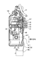
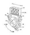
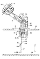
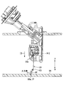
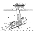
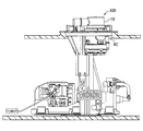
- FIG. 2 is a sectional view taken along line II-II in FIG. It is a perspective view of a liquid level detector. It is a figure which shows the process of assembling a fuel supply apparatus to a fuel tank. It is a figure which shows the process of assembling a fuel supply apparatus to a fuel tank. It is a figure which shows the process of assembling a fuel supply apparatus to a fuel tank. It is a figure which shows the process of assembling a fuel supply apparatus to a fuel tank. It is a figure which shows the process of assembling a fuel supply apparatus to a fuel tank. It is a figure which shows the process of assembling a fuel supply apparatus to a fuel tank.
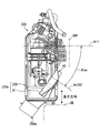
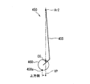
- FIG. 12 is a cross-sectional view taken along line XII-XII in FIG. 11. It is a figure which shows typically the structure of the liquid level detection unit by the modification 1. It is a figure which shows typically the structure of the liquid level detection unit by the modification 2.
- a fuel supply device 100 according to the first embodiment of the present disclosure shown in FIG. 1 is installed inside a fuel tank 90.
- the fuel tank 90 is formed in a hollow shape by a resin material or a metal material.
- the fuel tank 90 is mounted on the vehicle together with the internal combustion engine 110 and stores liquid fuel such as gasoline or light oil consumed by the internal combustion engine 110.
- a circular insertion opening 92 is provided in the ceiling wall 91 of the fuel tank 90.
- a part of the configuration of the fuel supply device 100 is inserted into the fuel tank 90 through the insertion opening 92.
- positioned inside the fuel tank 90 substantially corresponds with the vertical direction of the vehicle stopped on the horizontal surface.
- the fuel supply device 100 includes a flange 10, a sub tank 20, a support 30, a liquid level detector 40, and the like.
- the flange 10 is formed in a disk shape as a whole by a resin material.
- the flange 10 closes the insertion opening 92 by being attached to the ceiling wall 91 of the fuel tank 90.
- a fuel supply pipe 11 and a connector 12 are formed on the flange 10.
- the fuel supply pipe 11 forms a fuel path through which the fuel supplied from the sub tank 20 flows to the internal combustion engine 110.
- a plug portion electrically connected to the control circuit system 120 is fitted to the connector 12.
- the sub tank 20 is accommodated in the fuel tank 90 and is located below the flange 10.
- the sub tank 20 is formed in a longitudinal shape as a whole, and is pressed against the bottom wall surface 94 in an installation posture in which the longitudinal direction is along the inner surface (hereinafter referred to as “bottom wall surface”) 94 of the bottom wall 93 of the fuel tank 90. ing.
- the sub tank 20 includes a sub tank main body 21 and a fuel pump 22.
- the sub tank main body 21 is formed in a flat rectangular parallelepiped shape as a whole.
- the sub tank main body 21 is placed on the bottom wall surface 94 of the fuel tank 90.
- the fuel stored in the fuel tank 90 flows into the sub tank main body 21.
- the sub tank main body 21 temporarily stores the fuel sucked into the fuel pump 22.
- the fuel pump 22 is an electric pump such as an impeller pump or a trochoid pump.
- the fuel pump 22 is formed in a cylindrical shape as a whole.
- the fuel pump 22 is fixed to the sub tank main body 21 in a posture in which the axial direction is along the longitudinal direction of the sub tank 20.
- the fuel pump 22 is connected to the connector 12 via a flexible wiring that can be bent.
- a control signal is supplied from the control circuit system 120 to the fuel pump 22 via the connector 12.
- the fuel pump 22 is controlled by the control circuit system 120 to suck in the fuel stored in the sub tank main body 21.
- the fuel pump 22 supplies the fuel sucked in the fuel tank 90 to the internal combustion engine 110 outside the fuel tank 90.
- the support column 30 is accommodated inside the fuel tank 90.
- the support column 30 mechanically connects the flange 10 and the sub tank 20 independently.
- pillar 30 is supporting the subtank 20 rotatably.
- the column 30 includes a lower column 31, an upper column 32, and an elastic member 33.
- the lower column part 31 and the upper column part 32 are made of a resin material.
- the lower column 31 is attached to the sub tank main body 21.
- the lower support column 31 is rotatable relative to the sub tank main body 21 around the virtual main body rotation axis Ar1.
- the support column 30 supports the sub tank 20 so as to be rotatable about the main body rotation axis Ar ⁇ b> 1 as a rotation center.
- the main body rotation axis Ar ⁇ b> 1 is defined at a position shifted to one side from the longitudinal center of the sub tank 20.
- the main body rotation axis Ar ⁇ b> 1 is in a posture along the bottom wall surface 94.
- the upper support column 32 is formed in a cylindrical shape extending downward from the flange 10.
- the lower column 31 is slidably fitted to the upper column 32 from below.
- the elastic member 33 is a coil spring formed of a metal material.
- the elastic member 33 is disposed in a state of being compressed between the lower support column portion 31 and the upper support column portion 32.
- the elastic member 33 applies a downward restoring force to the lower support 31.
- the sub tank 20 is pressed against the bottom wall 93 by fixing the flange 10 to the ceiling wall 91. Further, the relative position between the lower support column 31 and the upper support unit 32 can be changed according to the expansion and contraction of the fuel tank 90.
- the liquid level detector 40 shown in FIGS. 1 to 3 is accommodated in the fuel tank 90 together with the sub tank 20.
- the liquid level detector 40 detects the height of the liquid level of the fuel stored in the fuel tank 90 by using the float 60 floating on the fuel.
- the liquid level detector 40 includes a sender body 41 and a liquid level detection unit 50.
- the sender body 41 is made of a resin material.
- the sender body 41 is fixed to the sub tank 20 by being attached to the sub tank main body 21.
- the sender body 41 and the sub tank 20 constitute a supply main body 20a that rotatably supports the liquid level detection unit 50.
- the sender body 41 accommodates a Hall IC.
- the Hall IC is a sensor that detects the rotational phase of the liquid level detection unit 50.
- a plurality of pairs of upper limit stoppers 42 and lower limit stoppers 43 are formed on the sender body 41.
- the upper limit stopper 42 and the lower limit stopper 43 are arranged to face each other in the vertical direction.
- the liquid level detection unit 50 can rotate relative to the supply main body 20a around the virtual rotation center axis Ar2.
- the virtual rotation center axis Ar2 is defined in a posture along the main body rotation axis Ar1. Therefore, when the supply main body 20a (sub tank 20) is in the installation posture, the posture is along the bottom wall surface 94.
- the rotation center axis Ar2 is located above the main body rotation axis Ar1 of the supply main body 20a.
- the rotation center axis Ar2 is located on the opposite side of the main body rotation axis Ar1 across the center in the longitudinal direction of the supply main body 20a.
- the liquid level detection unit 50 includes a magnet holder 51, a sender arm 55, and a float 60.
- the magnet holder 51 is formed in a disk shape as a whole by a resin material.
- the magnet holder 51 houses a pair of magnets.
- the pair of magnets are arranged so as to sandwich the Hall IC, and apply a magnetic field to the Hall IC.
- a plurality of stopper holes 52 are formed in the magnet holder 51.
- the sender arm 55 is formed of a metal material in a round bar shape. One end of the sender arm 55 is bent with respect to the main body. The sender arm 55 is attached to the magnet holder 51 in a state where one end portion is inserted into any one of the plurality of stopper holes 52. One end inserted through the stopper hole 52 comes into contact with the upper limit stopper 42 and the lower limit stopper 43 by the rotation of the liquid level detection unit 50.
- the float 60 is formed in a flat rectangular parallelepiped shape as a whole by a material such as foamed ebonite. Each side of the float 60 is rounded and chamfered by a minute (several mm) R.
- the float 60 is attached to the other end of the sender arm 55.
- the float 60 can float on the liquid level of the fuel, and is displaced in the vertical direction following the change in the liquid level of the fuel while sliding in the longitudinal direction along the liquid level. Due to the vertical displacement of the float 60, the liquid level detection unit 50 rotates relative to the supply main body 20a.
- one end of the sender arm 55 comes into contact with the upper limit stopper 42 due to the upward displacement of the float 60 as the liquid level rises. Thereby, the upward displacement of the float 60 and the upward rotation of the liquid level detection unit 50 are restricted. As a result, contact of the float 60 with the ceiling wall 91 is prevented.
- the liquid level detector 40 detects the rotational phase of the liquid level detection unit 50 that rotates due to the displacement of the float 60 using a Hall IC.
- the Hall IC is electrically connected to an in-vehicle device provided outside the fuel tank 90, for example, a combination meter. When the detection result of the Hall IC is acquired by the combination meter, information indicating the remaining amount of fuel is provided to the driver of the vehicle.
- the sub tank 20 and the liquid level detector 40 are inserted into the fuel tank 90 through the insertion opening 92.
- the configuration and function for preventing the damage of the liquid level detector 40 during such insertion work, and the respective assembly steps including the insertion work will be described below with reference to FIGS. 4 to 10, the sub tank 20 and the liquid level detector 40 are inserted in a posture in which the longitudinal direction of the supply main body portion 20a is along the vertical direction as the worst state in which the float 60 is most likely to interfere with the bottom wall surface 94. The case where it inserts in the opening 92 is shown.
- the insertion direction ID used in the following description is a direction defined with respect to the supply main body 20a, and specifically, the rotation center from the main body rotation axis Ar1 along the longitudinal direction of the supply main body 20a.
- the direction is toward the axis Ar2.
- the “upper side” and “lower side” used so far are relative directions defined with respect to the supply main body portion 20a, and are therefore used in the following description, distinguished from the absolute vertical direction.
- the rotation direction of the liquid level detection unit is also based on the “upper side” and “lower side” of the supply main body 20a in the installed state.
- the direction approaching the ceiling wall 91 in the installed state is the “upper side”
- the direction approaching the bottom wall 93 is the “lower side”.
- the left side with respect to the rotation center axis Ar2 is “upper side”
- the right side with respect to the rotation center axis Ar2 is “downward”. Side ".
- insertion form As shown in FIG. 4, the form of the fuel supply device 100 at the start of the insertion operation (hereinafter referred to as “insertion form”) ", See Fig. 1).
- the support column 30 in the insertion form is in a state of being most stretched in the axial direction by the restoring force of the elastic member 33 (see FIG. 2).
- the relative posture of the supply main body 20a with respect to the support column 30 differs between the insertion form and the installation form.
- the supply main body 20a in the insertion configuration is in an insertion posture in which the support portion of the liquid level detection unit 50 is relatively rotated downward with respect to the support column 30 as compared with the state of the installation configuration.
- a virtual line that extends along the extending direction of the support column 30 and intersects with the main body rotation axis Ar1 on a virtual vertical plane orthogonal to the main body rotation axis Ar1 is defined as a support axis CAL.
- a virtual line that extends along the longitudinal direction of the supply main body 20a and intersects the main body rotation axis Ar1 on the vertical plane is defined as a main body axis BAL.
- the angle formed by the support axis CAL and the main body axis BAL is substantially 90 degrees when the supply main body 20a is in the installation posture.
- the angle formed by the support axis CAL and the main body axis BAL is an obtuse angle of 90 degrees or more, and is expanded to, for example, about 130 degrees.
- the rotation range of the liquid level detection unit 50 is defined to include at least the space in the insertion direction ID of the supply main body 20a.
- the supply main body 20 a is inserted into the insertion opening 92 in a posture in which a specific insertion direction ID is directed to the insertion opening 92.
- the support column 30 and the flange 10 and the supply main body 20a are each gripped by an operator.
- the insertion opening can be freely rotated with respect to the supply main body 20a. 92.
- the liquid level detection unit 50 passes through the insertion opening 92 in a state where the liquid level detection unit 50 hangs down from the supply body 20a due to the action of gravity. That is, the liquid level detection unit 50 is inserted into the insertion opening 92 at a rotation phase in which the center of gravity CG is positioned in the gravity direction (directly below) the rotation center axis Ar2 in the rotation range.
- the tip 50a farthest from the rotation center axis Ar2 in the liquid level detection unit 50 is in the insertion direction ID most in the supply body 20a and the liquid level detection unit 50 inserted into the insertion opening 92. It becomes a part to be located.
- one side farthest from the rotation center axis Ar2 is the tip 50a.
- the tip 50a first contacts the bottom wall surface 94 (see FIG. 5).
- the liquid level detection unit 50 is rotated downward by a force acting on the tip 50a from the bottom wall surface 94, one end of the sender arm 55 is strongly pressed against the lower limit stopper 43 (see FIG. 3). It will be. As a result, breakage may occur at each location of the liquid level detector 40.
- the tip 50a of the liquid level detection unit 50 is provided above the rotation direction of the liquid level detection unit 50 with respect to a virtual plane VP including the rotation center axis Ar2 and the center of gravity CG. Yes.
- the virtual plane VP becomes substantially parallel to the vertical direction due to the gravity acting on the liquid level detection unit 50. Therefore, the liquid level detection unit 50 that is freely rotatable with respect to the supply main body 20a during the insertion operation is in a state in which the tip 50a is positioned on the upper side with respect to the rotation center axis Ar2.
- the distal end portion 50 a moved in the insertion direction ID by continuing the insertion operation of the supply main body portion 20 a and the liquid level detection unit 50 interferes with the bottom wall surface 94.
- the contact point IP between the tip 50a and the bottom wall surface 94 is above the rotation center axis Ar2. Therefore, the reaction force RF that acts on the tip 50a from the bottom wall surface 94 at the contact location IP is a force that rotates the liquid level detection unit 50 upward.
- the supply main body 20 a passes through the insertion opening 92, the operator rotates the entire fuel supply device 100.
- the supply main body 20a is gradually rotated in a direction in which the supply main body 20a rises from a posture along the vertical direction to a posture along the bottom wall surface 94.
- the reaction force RF (see FIG. 5) acting on the float 60 from the bottom wall surface 94 gradually disappears, so that the liquid level detection unit 50 starts to rotate downward due to the action of gravity.
- the downward rotation of the liquid level detection unit 50 is performed within a predetermined rotation range. Therefore, a load that leads to breakage does not act on the liquid level detection unit 50.
- the supply main body portion 20 a seats the bottom surface on the bottom wall surface 94 by the relative rotation with respect to the support column 30.
- the angle formed between the support axis CAL and the main body axis BAL around the main body rotation axis Ar1 is substantially 90 degrees.
- the supply main body portion 20a has an installation posture in which the supply main body portion 20a is rotated upward with respect to the support column 30 with respect to the insertion posture capable of passing through the insertion opening 92.
- the operator presses the flange 10 toward the insertion opening 92 against the restoring force of the elastic member 33 (see FIG. 2).
- the insertion opening 92 is blocked by the flange 10.
- the tip 50a is provided on the upper side with respect to the virtual plane VP including the rotation center axis Ar2 and the center of gravity CG. Therefore, even if the tip 50a comes into contact with the bottom wall surface 94 by the insertion operation, these contact locations IP are located above the rotation center axis Ar2 (see FIG. 5). As a result, the liquid level detection unit 50 can rotate upward due to the force acting on the float 60 from the bottom wall surface 94.
- the liquid level detection unit 50 is prevented from rotating downward, the liquid level detection unit 50 is strongly pressed against the lower limit stopper 43 by the force acting on the float 60 from the bottom wall surface 94. Can be prevented. Therefore, damage to the liquid level detection unit 50 and the lower limit stopper 43 before use of the fuel supply device 100 is avoided.
- the fuel supply device 100 of the first embodiment has a configuration in which the supply main body 20 a can rotate with respect to the support column 30. Then, the supply main body portion 20a is inserted into the insertion opening 92 in an insertion posture in which the supply main body portion 20a is rotated downward relative to the support column 30 with respect to the installation posture of the supply main body portion 20a.
- the rotation range of the liquid level detection unit 50 is defined in the space of the insertion direction ID of the supply main body portion 20a in order to enable insertion into the insertion opening 92 having a limited opening area. The Therefore, the above-described configuration in which the damage is avoided by preventing the rotation to the lower side is particularly effective for the fuel supply device 100 in which the supply main body portion 20 a can rotate with respect to the support column 30.
- the rotation center axis Ar2 of the liquid level detection unit 50 is located above the main body rotation axis Ar1 of the supply main body 20a. Therefore, when the supply main body 20a rotates relatively upward with respect to the support column 30, the float 60 is quickly lifted up and separated from the bottom wall surface 94 (see FIG. 5). According to the above, breakage of the liquid level detector 40 during the insertion work is less likely to occur.
- the rotation center axis Ar2 is defined in a posture along the main body rotation axis Ar1. Therefore, when starting the insertion operation, if the longitudinal direction of the supply main body 20a is aligned with the axial direction of the insertion opening 92, the rotation center axis Ar2 is also in a posture along the horizontal direction (see FIG. 4). According to the above, since the liquid level detection unit 50 is easily rotated smoothly with respect to the supply main body 20a at the start of the insertion operation, the center of gravity CG is reliably positioned in the gravity direction of the rotation center axis Ar2. Can do.
- a fuel supply device 200 according to the second embodiment of the present disclosure shown in FIGS. 11 and 12 is a modification of the first embodiment.
- the mounting posture of the liquid level detector 40 with respect to the sub tank 220 is different from that of the first embodiment.
- the liquid level detector 40 is fixed to the sub tank 220 so that the rotation center axis Ar202 is inclined with respect to the main body rotation axis Ar1. According to the mounting posture of the liquid level detector 40 as described above, it is possible to set the rotation range of the liquid level detection unit 50 while avoiding the obstacle OB present in the fuel tank 90.
- the rotation center axis Ar202 of the second embodiment is set to a posture along the bottom wall surface 94, similarly to the main body rotation axis Ar1.
- the rotation center axis Ar202 and the main body rotation axis Ar1 are projected on the same virtual horizontal plane along the vertical direction (see FIG. 12)
- the rotation center axis Ar202 is the main body rotation axis Ar1 on the virtual horizontal plane. It is inclined with respect to.
- the tilt angle ⁇ ax of the second embodiment is set to about 35 °, for example.
- the rotation center axis Ar202 of the second embodiment described so far is defined in a posture intersecting with a virtual orthogonal plane VOP orthogonal to the main body rotation axis Ar1, and is not parallel to the orthogonal plane VOP. Therefore, even if the longitudinal direction of the supply main body 220a is set in the vertical direction during the insertion operation, the rotation center axis Ar202 is not vertical. According to the above, the liquid level detection unit 50 can rotate with respect to the supply main body 220a at the start of the insertion work, and can position the tip 250a above the rotation center axis Ar202. Accordingly, even in the fuel supply device 200 of the second embodiment, damage to the liquid level detector 40 is avoided. In the second embodiment, among the plurality of corner portions formed in the float 60, one corner portion farthest from the rotation center axis Ar202 and farthest from the supply main body portion 20a is the tip portion. 250a.
- the sender arm 55 of the above embodiment has a shape in which an intermediate portion is curved downward in the rotational direction. Moreover, the float 60 of the said embodiment was formed in the flat rectangular parallelepiped shape. However, if the tip can be positioned above the virtual plane VP including the rotation center axis and the center of gravity, the shapes of the sender arm and the float can be changed as appropriate.
- the liquid level detection unit 350 of the first modification shown in FIG. 13 includes a sender arm 355 and a float 360 having shapes different from those of the first embodiment.
- An intermediate portion of the sender arm 355 is curved or bent upward in the rotational direction of the liquid level detection unit 350.
- the float 360 is formed in a triangular prism shape, and is attached to the sender arm 355 in a posture in which the axial direction is along the rotation center axis Ar2.
- the tip portion 350 a of the liquid level detection unit 350 is the tip portion 350 a of the liquid level detection unit 350.
- the tip 350a is located above the virtual plane VP including the rotation center axis Ar2 and the center of gravity CG. Therefore, even in the first modification, damage to the liquid level detection unit 350 due to interference with the bottom wall surface 94 (see FIG. 4) during the insertion operation is prevented.
- the 14 also includes a sender arm 455 and a float 460 having shapes different from those of the first embodiment.
- An intermediate portion of the sender arm 455 is curved or bent downward in the rotational direction of the liquid level detection unit 450.
- the float 460 is formed in a columnar shape, and is attached to the sender arm 455 in a posture in which the axial direction is along the rotation center axis Ar2.
- a strip-like region farthest from the rotation center axis Ar2 is the tip portion 450a of the liquid level detection unit 450.
- the tip portion 450a is located above the virtual plane VP including the rotation center axis Ar2 and the center of gravity CG. Therefore, even in the second modification, damage to the liquid level detection unit 450 due to interference with the bottom wall surface 94 (see FIG. 4) during insertion work is prevented.
- the tip may form other parts of the liquid level detection unit other than the float.
- the float forms the tip portion, it is desirable that the surface roughness of the outer surface of the float is set to a value that allows the bottom wall surface to slide smoothly without being in close contact with the bottom wall surface.
- the shape of the tip portion may be any of a planar shape, a linear shape, and a dotted shape.
- a plurality of locations farthest from the rotation center axis may be defined as the tip portion. With such a form, all the front-end
- tip parts are provided in the upper surface side rather than a virtual plane.
- the inclination angle ⁇ ax viewed from above can be appropriately changed. Specifically, the inclination angle may be changed as appropriate within the range of 0 ° ⁇ ⁇ ax ⁇ 90 °. Within such an angle range, the liquid level detection unit can rotate with respect to the supply main body during insertion work by the action of gravity.
- the rotation center axis Ar202 of the second embodiment is defined horizontally, the rotation center axis may be defined in a posture inclined with respect to the bottom wall surface or the horizontal plane. As described above, if the rotation center axis is defined in a posture that intersects the orthogonal plane VOP, an effect of avoiding damage and deformation by rotating the liquid level detection unit upward can be exhibited.
- the “upper side” and the “lower side” of the rotation direction of the liquid level detection unit are the supply main body in the installed state, regardless of how the liquid level detector is attached to the sub tank. Defined on the basis of the part. That is, the liquid level detection unit in the installed state rotates to the “upper side” by the rise of the liquid level and to the “lower side” by the drop of the liquid level, regardless of the posture of the rotation center axis. Rotate.
- the upper limit stopper and the lower limit stopper are provided in the sender body among the sub tank and the sender body constituting the supply main body.
- at least one of the upper limit stopper and the lower limit stopper is not a sender body but a member or a part provided in the sub tank, and can be formed by a configuration formed so as to protrude on the rotation track of the liquid level detection unit. .
- the main body rotation axis Ar1 and the rotation center axis Ar2 of the above embodiment were arranged on opposite sides of the center of the supply main body in the longitudinal direction.
- the main body rotation axis Ar1 and the rotation center axis Ar2 may be arranged on the same side with respect to the center in the longitudinal direction of the supply main body.
- the liquid level detector 40 (see FIG. 3) of the above embodiment has a detection configuration that detects the rotational phase of the liquid level detection unit using a Hall IC and a magnet.
- the detection configuration of the liquid level detector can be changed as appropriate.
- a liquid level detector that outputs the rotational phase of the liquid level detection unit as a resistance value by a detection configuration in which the variable resistance value and the sliding freight are displaced relative to each other may be provided in the fuel supply device.
- the fuel supply device of the above embodiment has a configuration in which the supply main body is rotated around the main body rotation axis with respect to the flange and the support in the fuel tank.
- the supply main body portion may simply be slid with respect to the flange and the support column, and may not be rotated with respect to these.
- the rotation center axis of the above embodiment is defined on the upper side of the main body rotation axis.
- the vertical position of the main body rotation axis and the rotation center axis in the supply main body may be aligned with each other.
- the main body rotation axis may be provided above the rotation center axis.
Landscapes
- Engineering & Computer Science (AREA)
- Chemical & Material Sciences (AREA)
- Combustion & Propulsion (AREA)
- Mechanical Engineering (AREA)
- General Engineering & Computer Science (AREA)
- Level Indicators Using A Float (AREA)
- Cooling, Air Intake And Gas Exhaust, And Fuel Tank Arrangements In Propulsion Units (AREA)
Abstract
燃料供給装置(100)は、燃料に浮かぶフロート(60)を用いて液面の高さを検出する液面検出器(40)を含んでいる。燃料供給装置(100)の供給本体部(20a)は、挿入開口(92)を通じて燃料タンク(90)の内部に配置され、燃料タンク(90)の外部に燃料を供給する。フロート(60)を有する液面検出ユニット(50)は、供給本体部(20a)に対して相対回転可能であり、供給本体部(20a)の挿入方向(ID)を少なくとも含むよう回転範囲を規定されている。液面検出ユニット(50)のうちで仮想の回転中心軸線(Ar2)から最も遠い先端部(50a)は、回転中心軸線(Ar2)と液面検出ユニット(50)の重心(CG)とを含む仮想平面(VP)に対して、液面検出ユニット(50)の回転方向の上方側に設けられている。
Description
本願は、2016年4月28日に出願された日本国特許出願第2016-90582号に基づくものであり、この開示をもってその内容を本明細書中に開示したものとする。
この明細書による開示は、燃料タンク内に配置され、燃料タンクの燃料を内燃機関へ供給する燃料供給装置に関する。
従来、例えば特許文献1には、フロートを用いて燃料の液面の高さを検出するセンダゲージを備えた燃料供給装置が開示されている。センダゲージは、燃料供給装置のポンプユニットに固定される本体、並びにポンプユニットに対して相対回転可能なゲージアーム及びフロート等の液面検出ユニットを有している。燃料供給装置のポンプユニット及びセンダゲージは、挿入開口を通じて燃料タンクに挿入され、燃料タンクの内部に配置される。
一般に、センダゲージの本体には、回転可能な液面検出ユニットの変位を規制することで、液面検出ユニットの回転範囲を規定するストッパが設けられている。加えて特許文献1のように、液面検出ユニットの回転範囲は、ポンプユニットの挿入方向を少なくとも含むよう規定されている。そのため、ポンプユニット等を燃料タンクに挿入する挿入作業に際して、液面検出ユニットの先端側に取り付けられたフロートは、燃料タンクの底壁面に接触して、底壁面から反力を受ける。
ここで、特許文献1のフロートは、燃料タンクに貯留された燃料の残量が僅かとなった場合でも燃料から浮力を受けて、底壁面近傍でも液面高さに追従できるように、回転方向の上方側よりも下方側に容積を持った形状とされている。そのため、挿入作業に際して、フロートが底壁面に干渉した場合、液面検出ユニットは、底壁面からフロートに作用する力によって下方側に回転し、下方側への変位を規制するストッパに強く押し当てられてしまい得る。その結果、液面検出ユニット及びストッパ等に破損が生じる虞があった。
本開示は、このような問題に鑑みてなされたものであり、その目的は、使用前における液面検出ユニット及びストッパ等の破損を回避可能な燃料供給装置を提供することにある。
上記目的を達成するため、開示された第一の態様は、燃料タンクに設けられた挿入開口に特定の挿入方向を向けた姿勢で供給本体部がこの挿入開口に挿入され、燃料に浮かぶフロートを用いて液面の高さを検出する液面検出器を含む燃料供給装置において、フロートの下方への変位を規制する下限ストッパを有し、燃料タンクの内部に配置されて、燃料タンクの外部に燃料を供給する供給本体部と、フロートを有し、供給本体部に対して相対回転可能であり、下限ストッパとの接触によって下方側への回転が制限され、供給本体部の挿入方向の空間を少なくとも含むように回転範囲が規定された液面検出ユニットと、を備え、液面検出ユニットのうちで仮想の回転中心軸線から最も遠い先端部は、回転中心軸線と液面検出ユニットの重心とを含む仮想平面に対して、液面検出ユニットの回転方向の上方側に設けられている燃料供給装置とする。
この態様によれば、燃料供給装置の供給本体部を燃料タンクの内部に挿入する挿入作業に際して、液面検出ユニットは、供給本体部の挿入方向に一部を位置させて、仮想の回転中心軸線の重力方向に、重心を位置させた姿勢をとる。このとき、液面検出ユニットのうちで回転中心軸線から最も遠い先端部は、回転中心軸線と重心とを含む仮想平面に対して、回転方向の上方側に位置する。故に、挿入作業によって、燃料タンクの底壁面に先端部が干渉した場合でも、液面検出ユニットは、底壁面から作用する力により、上方側へ向けて回転する。このように、液面検出ユニットの下方側への回転が阻止されれば、燃料タンクの底壁面から作用する力によって液面検出ユニットが下限ストッパに強く押し当てられる事態は、防がれ得る。したがって、燃料供給装置の使用前における液面検出ユニット及びストッパ等の破損は、回避される。
本開示についての上記目的およびその他の目的、特徴や利点は、添付の図面を参照しながら下記の詳細な記述により、より明確になる。
以下、本開示の複数の実施形態を図面に基づいて説明する。尚、各実施形態において対応する構成要素には同一の符号を付すことにより、重複する説明を省略する場合がある。各実施形態において構成の一部分のみを説明している場合、当該構成の他の部分については、先行して説明した他の実施形態の構成を適用することができる。また、各実施形態の説明において明示している構成の組み合わせばかりではなく、特に組み合わせに支障が生じなければ、明示していなくても複数の実施形態の構成同士を部分的に組み合わせることができる。そして、複数の実施形態及び変形例に記述された構成同士の明示されていない組み合わせも、以下の説明によって開示されているものとする。
(第一実施形態)
図1に示す本開示の第一実施形態による燃料供給装置100は、燃料タンク90の内部に設置されている。燃料タンク90は、樹脂材料又は金属材料によって中空状に形成されている。燃料タンク90は、内燃機関110と共に車両に搭載されており、内燃機関110によって消費されるガソリン又は軽油等の液体燃料を貯留している。燃料タンク90の天井壁91には、円形状の挿入開口92が設けられている。燃料供給装置100の構成の一部は、挿入開口92を通じて燃料タンク90の内部に挿入される。尚、燃料タンク90の内部に配置された構成の上下方向は、水平面上に停止した車両の鉛直方向と実質的に一致している。
図1に示す本開示の第一実施形態による燃料供給装置100は、燃料タンク90の内部に設置されている。燃料タンク90は、樹脂材料又は金属材料によって中空状に形成されている。燃料タンク90は、内燃機関110と共に車両に搭載されており、内燃機関110によって消費されるガソリン又は軽油等の液体燃料を貯留している。燃料タンク90の天井壁91には、円形状の挿入開口92が設けられている。燃料供給装置100の構成の一部は、挿入開口92を通じて燃料タンク90の内部に挿入される。尚、燃料タンク90の内部に配置された構成の上下方向は、水平面上に停止した車両の鉛直方向と実質的に一致している。
燃料供給装置100は、図1及び図2に示すように、フランジ10、サブタンク20、支柱30、及び液面検出器40等によって構成されている。
フランジ10は、樹脂材料によって全体として円板状に形成されている。フランジ10は、燃料タンク90の天井壁91に取り付けられることにより、挿入開口92を塞いでいる。フランジ10には、燃料供給管11及びコネクタ12が形成されている。燃料供給管11は、サブタンク20から供給された燃料を内燃機関110へ向けて流通させる燃料経路を形成している。コネクタ12には、制御回路系120と電気接続されたプラグ部が嵌合している。
サブタンク20は、燃料タンク90の内部に収容され、フランジ10の下方に位置している。サブタンク20は、全体として長手形状に形成されており、長手方向を燃料タンク90の底壁93の内面(以下、「底壁面」)94に沿わせた設置姿勢にて、底壁面94に押し付けられている。サブタンク20は、サブタンク本体部21及び燃料ポンプ22を有している。
サブタンク本体部21は、全体として偏平の直方体状に形成されている。サブタンク本体部21は、燃料タンク90の底壁面94に載置されている。サブタンク本体部21の内部には、燃料タンク90に貯留された燃料が流入する。サブタンク本体部21は、燃料ポンプ22に吸入される燃料を一時的に貯留している。
燃料ポンプ22は、例えばインペラポンプ又はトロコイドポンプ等の電動ポンプである。燃料ポンプ22は、全体として円柱状に形成されている。燃料ポンプ22は、軸方向をサブタンク20の長手方向に沿わせた姿勢で、サブタンク本体部21に固定されている。燃料ポンプ22は、湾曲自在なフレキシブル配線を介して、コネクタ12と接続されている。燃料ポンプ22には、制御回路系120から制御信号がコネクタ12を経由して供給される。燃料ポンプ22は、サブタンク本体部21に貯留された燃料を吸入する作動を、制御回路系120によって制御される。燃料ポンプ22は、燃料タンク90の内部にて吸入した燃料を、燃料タンク90の外部の内燃機関110に供給する。
支柱30は、燃料タンク90の内部に収容されている。支柱30は、フランジ10とサブタンク20とを単独で機械的に連結している。支柱30は、サブタンク20を回転可能に支持している。支柱30は、ロア支柱部31、アッパ支柱部32、及び弾性部材33等によって構成されている。
ロア支柱部31及びアッパ支柱部32は、樹脂材料によって形成されている。ロア支柱部31は、サブタンク本体部21に取り付けられている。ロア支柱部31は、サブタンク本体部21に対して、仮想の本体回転軸線Ar1まわりに相対回転可能である。こうしたロア支柱部31の構成により、支柱30は、本体回転軸線Ar1を回転中心として、サブタンク20を回転可能に支持している。本体回転軸線Ar1は、サブタンク20の長手方向の中央から一方にずれた位置に規定されている。サブタンク20が設置姿勢である場合、本体回転軸線Ar1は、底壁面94に沿った姿勢となる。アッパ支柱部32は、フランジ10から下方に延伸した筒状に形成されている。アッパ支柱部32には、ロア支柱部31が下方からスライド嵌合している。
弾性部材33は、金属材料によって形成されたコイルスプリングである。弾性部材33は、ロア支柱部31とアッパ支柱部32との間に押し縮められた状態で配置されている。弾性部材33は、下方へ向かう復元力をロア支柱部31に作用させる。以上の構成によれば、フランジ10の天井壁91への固定により、サブタンク20は、底壁93に押し付けられる。また、ロア支柱部31とアッパ支柱部32との相対位置は、燃料タンク90の膨縮に応じて変化可能となる。
図1~図3に示す液面検出器40は、サブタンク20と共に燃料タンク90の内部に収容されている。液面検出器40は、燃料に浮かぶフロート60を用いることにより、燃料タンク90に貯留されている燃料の液面の高さを検出する。液面検出器40は、センダボディ41及び液面検出ユニット50を有している。
センダボディ41は、樹脂材料によって形成されている。センダボディ41は、サブタンク本体部21への取り付けによって、サブタンク20に固定されている。センダボディ41及びサブタンク20は、液面検出ユニット50を回転可能に支持する供給本体部20aを構成している。センダボディ41には、ホールICが収容されている。ホールICは、液面検出ユニット50の回転位相を検出するセンサである。センダボディ41には、複数対の上限ストッパ42及び下限ストッパ43が形成されている。上限ストッパ42及び下限ストッパ43は、上下方向に対向配置されている。
液面検出ユニット50は、供給本体部20aに対して、仮想の回転中心軸線Ar2まわりに相対回転可能である。仮想の回転中心軸線Ar2は、本体回転軸線Ar1に沿った姿勢に規定されている。そのため、供給本体部20a(サブタンク20)が設置姿勢である場合に、底壁面94に沿った姿勢となる。加えて回転中心軸線Ar2は、供給本体部20aの本体回転軸線Ar1よりも上方側に位置している。また回転中心軸線Ar2は、供給本体部20aの長手方向の中央を挟んで、本体回転軸線Ar1とは反対側に位置している。
液面検出ユニット50には、マグネットホルダ51、センダアーム55、及びフロート60が含まれている。
マグネットホルダ51は、樹脂材料によって全体として円板状に形成されている。マグネットホルダ51には、一対のマグネットが収容されている。一対のマグネットは、ホールICを挟むように配置され、ホールICに磁場を作用させている。マグネットホルダ51には、複数のストッパ孔52が形成されている。
センダアーム55は、金属材料によって丸棒状に形成されている。センダアーム55の一方の端部は、本体部分に対して屈曲されている。センダアーム55は、一方の端部を複数のストッパ孔52のいずれか一つに挿通させた状態で、マグネットホルダ51に取り付けられている。ストッパ孔52に挿通された一方の端部は、液面検出ユニット50の回転によって上限ストッパ42及び下限ストッパ43と接触する。
フロート60は、発泡させたエボナイト等の材料により、全体として扁平の直方体状に形成されている。フロート60の各辺は、微小(数mm)なRによって丸く面取りされている。フロート60は、センダアーム55の他方の端部に取り付けられている。フロート60は、燃料の液面に浮揚可能であり、液面に沿って長手方向にスライドしつつ燃料の液位の変化に追従して上下方向に変位する。フロート60の上下方向の変位により、液面検出ユニット50は、供給本体部20aに対して相対回転する。
以上の液面検出ユニット50では、液位の上昇に伴うフロート60の上方への変位により、センダアーム55の一方の端部が上限ストッパ42と接触する。これにより、フロート60の上方への変位及び液面検出ユニット50の上方側への回転が制限される。その結果、フロート60の天井壁91への接触が防がれる。
また、液位の降下に伴うフロート60の下方への変位によれば、センダアーム55の端部が下限ストッパ43と接触する。これにより、フロート60の下方への変位及び液面検出ユニット50の下方側への回転が制限される。その結果、フロート60の底壁93への接触が防がれる。
液面検出器40は、フロート60の変位によって回転する液面検出ユニット50の回転位相を、ホールICを用いて検出する。ホールICは、燃料タンク90の外部に設けられた車載機器、例えばコンビニネーションメータと電気接続されている。ホールICの検出結果がコンビネーションメータに取得されることで、燃料残量を示す情報が車両の運転者等に提供される。
以上の燃料供給装置100では、上述したように、サブタンク20及び液面検出器40等が挿入開口92を通じて燃料タンク90の内部に挿入される。こうした挿入作業の際に液面検出器40の破損を防止する構成及び機能と、挿入作業を含む各組み付け工程とを、図4~図10に基づいて以下説明する。図4~図10には、フロート60が底壁面94に最も干渉し易い最悪状態として、供給本体部20aの長手方向を上下方向に沿わせた姿勢で、サブタンク20及び液面検出器40を挿入開口92に挿入した場合が示されている。
ここで、以下の説明で用いる挿入方向IDは、供給本体部20aに対して規定された方向であり、具体的には、供給本体部20aの長手方向に沿って、本体回転軸線Ar1から回転中心軸線Ar2へ向かう方向とする。また、ここまで使用した「上方側」及び「下方側」は、供給本体部20aに対し規定された相対的な方向であるため、絶対的な上下方向とは区別して、以下の説明でも使用する。加えて、液面検出ユニットの回転方向についても、設置状態における供給本体部20aの「上方側」及び「下方側」を基準とする。即ち、供給本体部20aの姿勢が挿入作業に際してどのような向きに変化しても、設置状態にて天井壁91に近づく方向が「上方側」であり、底壁93に近づく方向が「下方側」となる。具体的に、液面検出器40を正面から見た図4~図10においては、回転中心軸線Ar2に対して左方側が「上方側」となり、回転中心軸線Ar2に対して右方側が「下方側」となる。
図4に示すように、挿入作業の開始時における燃料供給装置100の形態(以下、「挿入形態」)は、燃料タンク90に設置された状態の燃料供給装置100の形態(以下、「設置形態」,図1参照)とは異なる。
具体的に、挿入形態における支柱30は、弾性部材33(図2参照)の復元力によって軸方向に最も延伸した状態となっている。加えて、挿入形態と設置形態とでは、支柱30に対する供給本体部20aの相対的な姿勢が異なっている。挿入形態における供給本体部20aは、設置形態の状態よりも、液面検出ユニット50の支持部分を、支柱30に対して下方側に相対回転した挿入姿勢とされている。詳記すると、本体回転軸線Ar1に直交する仮想の垂直平面上にて、支柱30の延伸方向に沿い、且つ、本体回転軸線Ar1と交差する仮想線を支柱軸線CALとする。また、上記の垂直平面上にて、供給本体部20aの長手方向に沿い、且つ、本体回転軸線Ar1と交差する仮想線を本体軸線BALとする。上記の垂直平面上にて、支柱軸線CALと本体軸線BALとがなす角度は、供給本体部20aが設置姿勢である場合、実質的に90度となる。一方で、供給本体部20aが挿入姿勢である場合、支柱軸線CALと本体軸線BALとがなす角度は、90度以上の鈍角とされ、例えば130度程度まで拡大される。
加えて、液面検出ユニット50の回転範囲は、供給本体部20aの挿入方向IDの空間を少なくとも含むよう規定されている。挿入作業に際して、供給本体部20aは、特定の挿入方向IDを挿入開口92に向けた姿勢にて、この挿入開口92に挿入される。このとき、支柱30及びフランジ10と供給本体部20aとは、それぞれ作業者によって把持される。一方で、液面検出ユニット50は、供給本体部20aに対して固定されておらず、且つ、作業者によっても把持されていないため、供給本体部20aに対して回転自由な状態で、挿入開口92に挿入される。そのため液面検出ユニット50は、重力の作用によって供給本体部20aから垂れ下がった状態で、挿入開口92を通過する。即ち、液面検出ユニット50は、回転範囲のうちで回転中心軸線Ar2の重力方向(真下)に重心CGを位置させた回転位相にて、挿入開口92に挿入される。
以上の状態では、液面検出ユニット50のうちで回転中心軸線Ar2から最も遠い先端部50aが、挿入開口92に挿入される供給本体部20a及び液面検出ユニット50のうちで最も挿入方向IDに位置する部分となる。第一実施形態では、回転中心軸線Ar2に沿うフロート60の四つの辺のうちで、回転中心軸線Ar2から最も離れた一辺が先端部50aとなる。先端部50aは、底壁面94と最初に接触する(図5参照)。このとき、仮に底壁面94から先端部50aに作用する力で液面検出ユニット50が下方側に回転した場合、センダアーム55の一方の端部は、下限ストッパ43(図3参照)に強く押し当てられてしまう。その結果、液面検出器40の各箇所に破損が生じ得る。
こうした破損を回避するため、液面検出ユニット50の先端部50aは、回転中心軸線Ar2と重心CGとを含む仮想平面VPに対して、液面検出ユニット50の回転方向の上方側に設けられている。挿入作業において、仮想平面VPは、液面検出ユニット50に作用する重力によって上下方向と実質的に平行となる。そのため、挿入作業に際して供給本体部20aに対し回転自由な液面検出ユニット50は、先端部50aを、回転中心軸線Ar2に対して上方側に位置させた状態となる。
図5に示すように、供給本体部20a及び液面検出ユニット50の挿入作業の継続によって挿入方向IDへ移動した先端部50aは、底壁面94と干渉する。このとき、先端部50aと底壁面94との接触箇所IPは、回転中心軸線Ar2の上方側となる。そのため、接触箇所IPにて底壁面94から先端部50aに作用する反力RFは、液面検出ユニット50を上方側へ回転させる力となる。
以上によれば、供給本体部20aの姿勢が概ね垂直状態に維持されたまま挿入作業が継続されても、図6に示すように、液面検出ユニット50は、R面取りされた先端部50aを底壁面94に対して上方側へ滑らせつつ、満タン指示側へと回動する。その結果、供給本体部20aは、サブタンク20と底壁面94との間からフロート60を退避させつつ、挿入開口92を通過することができる。
図7に示すように、挿入開口92を供給本体部20aが通過すると、作業者は、燃料供給装置100の全体を回転させる。こうした工程により、供給本体部20aは、長手方向を上下方向に沿わせた姿勢から、底壁面94に沿わせた姿勢へと、起き上がる方向に徐々に回転する。その結果、底壁面94からフロート60に作用する反力RF(図5参照)が徐々に消失するため、液面検出ユニット50は、重力の作用によって下方側への回転を開始する。この液面検出ユニット50の下方側への回転は、所定の回転範囲内で行われる。故に、破損に繋がるような負荷は、液面検出ユニット50に作用しない。
図8に示すように、供給本体部20aが底壁面94に到達すると、底壁面94からの反力は、供給本体部20aに作用するようになる。故に、挿入方向IDへフランジ10を押し込む作業者の動作により、供給本体部20aは、本体回転軸線Ar1まわりに支柱30に対して上方側に回転する。以上によれば、支柱軸線CALと本体軸線BALとがなす角度は、挿入形態の際の鈍角から徐々に90度に近づいていく。その結果、センダアーム55の一方の端部と下限ストッパ43(図3参照)との接触が生じ、フロート60は、底壁面94から持ち上げられる。
図9に示すように、支柱30に対する相対回転により、供給本体部20aは、底壁面94に底面を着座させる。このとき、本体回転軸線Ar1を中心として支柱軸線CALと本体軸線BALとがなす角度は、実質的に90度となる。その結果、供給本体部20aは、挿入開口92を通過可能な挿入姿勢よりも、支柱30に対して上方側に回転した設置姿勢となる。作業者は、弾性部材33(図2参照)の復元力に抗して、フランジ10を挿入開口92へ向けて押し付ける。その結果、図10に示すように、フランジ10によって挿入開口92が塞がれる。以上により、燃料供給装置100の組み付ける一連の工程は完了する。
ここまで説明した第一実施形態の液面検出ユニット50において、先端部50aは、回転中心軸線Ar2と重心CGとを含む仮想平面VPに対して上方側に設けられている。故に、挿入作業によって底壁面94に先端部50aが接触しても、これらの接触箇所IPは、回転中心軸線Ar2よりも上方側となる(図5参照)。その結果、液面検出ユニット50は、底壁面94からフロート60に作用する力により、上方側へ向けて回転し得る。
以上のように、液面検出ユニット50の下方側への回転が阻止されれば、底壁面94からフロート60に作用する力により、液面検出ユニット50が下限ストッパ43に強く押し当てられる事態は、防がれ得る。したがって、燃料供給装置100の使用前における液面検出ユニット50及び下限ストッパ43等の破損は、回避される。
加えて第一実施形態の燃料供給装置100は、支柱30に対して供給本体部20aが回転可能な構成である。そして、設置時における供給本体部20aの設置姿勢よりも、支柱30に対して下方側に回転させた挿入姿勢にて、供給本体部20aは、挿入開口92に挿入される。こうした形態の燃料供給装置100では、開口面積の限られた挿入開口92への挿入を可能にするため、液面検出ユニット50の回転範囲は、供給本体部20aの挿入方向IDの空間に規定される。そのため、下方側への回転阻止によって破損を回避させる上述の構成は、供給本体部20aが支柱30に対して回転可能な燃料供給装置100に特に有効なのである。
また第一実施形態では、液面検出ユニット50の回転中心軸線Ar2が供給本体部20aの本体回転軸線Ar1よりも上方側に位置している。そのため、支柱30に対して供給本体部20aが上方側に相対回転すると、フロート60は、いち早く持ち上げられて、底壁面94から離間するようになる(図5参照)。以上によれば、挿入作業における液面検出器40の破損は、いっそう生じ難くなる。
さらに第一実施形態では、回転中心軸線Ar2は、本体回転軸線Ar1に沿った姿勢に規定されている。故に、挿入作業を開始するとき、供給本体部20aの長手方向を挿入開口92の軸方向に沿わせると、回転中心軸線Ar2も水平方向に沿った姿勢となる(図4参照)。以上によれば、液面検出ユニット50は、挿入作業の開始時において、供給本体部20aに対して円滑に回転し易くなるので、回転中心軸線Ar2の重力方向に重心CGを確実に位置させることができる。その結果、フロート60が干渉した際には、先端部50aと底壁面94との接触箇所IPは、確実に回転中心軸線Ar2の上方側となる。したがって、液面検出ユニット50を上方側に回転させて破損を回避する効果が安定的に発揮される。
(第二実施形態)
図11及び図12に示す本開示の第二実施形態による燃料供給装置200は、第一実施形態の変形例である。第二実施形態では、サブタンク220に対する液面検出器40の取り付け姿勢が、第一実施形態とは異なっている。液面検出器40は、回転中心軸線Ar202が本体回転軸線Ar1に対して傾斜した姿勢となるよう、サブタンク220に固定されている。以上のような液面検出器40の取り付け姿勢によれば、燃料タンク90の内部に存在する障害物OBを避けて、液面検出ユニット50の回転範囲を設定することが可能になる。
図11及び図12に示す本開示の第二実施形態による燃料供給装置200は、第一実施形態の変形例である。第二実施形態では、サブタンク220に対する液面検出器40の取り付け姿勢が、第一実施形態とは異なっている。液面検出器40は、回転中心軸線Ar202が本体回転軸線Ar1に対して傾斜した姿勢となるよう、サブタンク220に固定されている。以上のような液面検出器40の取り付け姿勢によれば、燃料タンク90の内部に存在する障害物OBを避けて、液面検出ユニット50の回転範囲を設定することが可能になる。
具体的に、第二実施形態の回転中心軸線Ar202は、本体回転軸線Ar1と同様に、底壁面94に沿った姿勢に設定されている。一方で、上下方向に沿って回転中心軸線Ar202及び本体回転軸線Ar1を同一の仮想水平面上に投影したとすると(図12参照)、この仮想水平面上において、回転中心軸線Ar202は、本体回転軸線Ar1に対して傾斜している。仮想水平面上において回転中心軸線Ar202と本体回転軸線Ar1とがなす角度を傾斜角度θaxとすると、第二実施形態の傾斜角度θaxは、例えば35°程度に設定されている。
ここまで説明した第二実施形態の回転中心軸線Ar202は、本体回転軸線Ar1に直交する仮想の直交平面VOPと交差した姿勢に規定されており、直交平面VOPと平行でない。故に、挿入作業の際に供給本体部220aの長手方向を上下方向に沿わせたとしても、回転中心軸線Ar202は、垂直とはならない。以上によれば、液面検出ユニット50は、挿入作業の開始時に供給本体部220aに対して回転し、先端部250aを回転中心軸線Ar202よりも上方側に位置させることができる。したがって、第二実施形態の燃料供給装置200でも、液面検出器40の破損は、回避される。尚、第二実施形態では、フロート60に形成される複数の角部のうちで、回転中心軸線Ar202から最も遠く、且つ、供給本体部20aから最も離れて位置する一つの角部が、先端部250aとなる。
(他の実施形態)
以上、複数の実施形態について説明したが、本開示は、上記実施形態に限定して解釈されるものではなく、本開示の要旨を逸脱しない範囲内において種々の実施形態及び組み合わせに適用することができる。
以上、複数の実施形態について説明したが、本開示は、上記実施形態に限定して解釈されるものではなく、本開示の要旨を逸脱しない範囲内において種々の実施形態及び組み合わせに適用することができる。
上記実施形態のセンダアーム55は、中間部分を回転方向の下方側に湾曲させた形状であった。また、上記実施形態のフロート60は、扁平の直方体状に形成されていた。しかし、回転中心軸線と重心とを含む仮想平面VPよりも上方側に先端部を位置させることができれば、センダアーム及びフロートの形状は、適宜変更可能である。
例えば図13に示す変形例1の液面検出ユニット350は、第一実施形態とは異なる形状のセンダアーム355及びフロート360を有している。センダアーム355の中間部分は、液面検出ユニット350の回転方向の上方側に湾曲又は屈曲している。フロート360は、三角柱状に形成されており、軸方向を回転中心軸線Ar2に沿わせた姿勢にて、センダアーム355に取り付けられている。回転中心軸線Ar2に沿うフロート360の三つの辺のうちで、回転中心軸線Ar2から最も遠い一辺が、液面検出ユニット350の先端部350aとなる。先端部350aは、回転中心軸線Ar2及び重心CGを含む仮想平面VPよりも上方側に位置している。そのため変形例1でも、挿入作業時における底壁面94(図4参照)との干渉に起因した液面検出ユニット350の破損は、防止される。
また図14に示す変形例2の液面検出ユニット450も、第一実施形態とは異なる形状のセンダアーム455及びフロート460を有している。センダアーム455の中間部分は、液面検出ユニット450の回転方向の下方側に湾曲又は屈曲している。フロート460は、円柱状に形成されており、軸方向を回転中心軸線Ar2に沿わせた姿勢にて、センダアーム455に取り付けられている。フロート460の円筒状の側面のうちで、回転中心軸線Ar2から最も遠い帯状の領域が、液面検出ユニット450の先端部450aとなる。先端部450aは、回転中心軸線Ar2及び重心CGを含む仮想平面VPよりも上方側に位置している。そのため変形例2でも、挿入作業時における底壁面94(図4参照)との干渉に起因した液面検出ユニット450の破損は、防止される。
さらに、液面検出ユニットのうちでフロートを除く他の部品が、先端部を形成していてもよい。また、フロートが先端部を形成する場合、フロートの外表面の面粗度は、底壁面に密着することなく、底壁面を円滑に滑り得る値に設定されることが望ましい。さらに先端部の形状は、面状、線状、及び点状のいずれであってもよい。加えて回転中心軸線から最も離れた複数の箇所が先端部として規定されてもよい。こうした形態では、全ての先端部が仮想平面よりも上面側に設けられる。
上記第二実施形態(図12参照)のように本体回転軸線Ar1に対して回転中心軸線Ar202が傾斜した形態において、上方から見た傾斜角度θaxは、適宜変更可能である。具体的に傾斜角度は、0°≦θax<90°の範囲で適宜変更されてよい。こうした角度範囲内であれば、液面検出ユニットは、重力の作用で挿入作業時に供給本体部に対し回転できる。
また、上記第二実施形態の回転中心軸線Ar202は、水平に規定されていたが、回転中心軸線は、底壁面又は水平面に対して傾斜した姿勢に規定されていてもよい。以上のように、回転中心軸線が直交平面VOPと交差する姿勢に規定されていれば、液面検出ユニットを上方側に回転させて損傷や変形を回避する効果が発揮可能となる。
さらに、サブタンクに対する液面検出器の取り付け姿勢がどのように規定されていても、上述したように、液面検出ユニットの回転方向の「上方側」及び「下方側」は、設置状態における供給本体部を基準に規定される。即ち、設置状態にある液面検出ユニットは、回転中心軸線がどのような姿勢で規定されていても、液位の上昇によって「上方側」に回転し、液位の降下によって「下方側」に回転する。
上記実施形態の上限ストッパ及び下限ストッパは、供給本体部を構成するサブタンク及びセンダボディのうちで、センダボディに設けられていた。しかし、上限ストッパ及び下限ストッパの少なくとも一方は、センダボディではなく、サブタンクに設けられた部材又は部位であって、液面検出ユニットの回転軌道上に突出するよう形成された構成によっても形成可能である。
上記実施形態の本体回転軸線Ar1及び回転中心軸線Ar2は、供給本体部の長手方向の中央を挟んで、互いに反対側に配置されていた。しかし、本体回転軸線Ar1及び回転中心軸線Ar2は、供給本体部の長手方向の中央に対して同じ側に配置されていてもよい。
上記実施形態の液面検出器40(図3参照)は、ホールICとマグネットとを用いて、液面検出ユニットの回転位相を検出する検出構成を備えていた。しかし、液面検出器の検出構成は、適宜変更可能である。例えば、可変抵抗値及び摺動フレートを互いに相対変位させる検出構成により、液面検出ユニットの回転位相を抵抗値として出力する液面検出器が、燃料供給装置に設けられていてもよい。
上記実施形態の燃料供給装置は、燃料タンクの内部において、フランジ及び支柱に対し、本体回転軸線を中心として、供給本体部を回転させる構成であった。しかし、供給本体部は、フランジ及び支柱に対して単にスライド変位するだけであり、これらに対して回転しない構成であってもよい。
上記実施形態の回転中心軸線は、本体回転軸線よりも上方側に規定されていた。しかし、供給本体部における本体回転軸線及び回転中心軸線の上下方向の位置は、互いに揃えられていてもよい。或いは、本体回転軸線は、回転中心軸線よりも上方側に設けられていてもよい。
Claims (5)
- 燃料タンク(90)に設けられた挿入開口(92)に特定の挿入方向(ID)を向けた姿勢で供給本体部(20a,220a)が当該挿入開口(92)に挿入され、燃料に浮かぶフロート(60,360,460)を用いて液面の高さを検出する液面検出器(40)を含む燃料供給装置において、
前記フロート(60,360,460)の下方への変位を規制する下限ストッパ(43)を有し、前記燃料タンク(90)の内部に配置されて、前記燃料タンク(90)の外部に燃料を供給する前記供給本体部(20a,220a)と、
前記フロート(60,360,460)を有し、前記供給本体部(20a,220a)に対して相対回転可能であり、前記下限ストッパ(43)との接触によって下方側への回転が制限され、前記供給本体部(20a,220a)の前記挿入方向(ID)の空間を少なくとも含むように回転範囲が規定された液面検出ユニット(50,350,450)と、を備え、
前記液面検出ユニット(50,350,450)のうちで仮想の回転中心軸線(Ar2,Ar202)から最も遠い先端部(50a,250a,350a,450a)は、前記回転中心軸線(Ar2,Ar202)と前記液面検出ユニット(50,350,450)の重心(CG)とを含む仮想平面(VP)に対して、前記液面検出ユニット(50,350,450)の回転方向の上方側に設けられている燃料供給装置。 - 仮想の本体回転軸線(Ar1)を回転中心として前記供給本体部(20a,220a)を回転可能に支持する支柱(30)、をさらに備え、
前記燃料タンク(90)の内部に設置された状態での前記供給本体部(20a,220a)の設置姿勢は、前記挿入開口(92)を通過可能な前記供給本体部(20a,220a)の挿入姿勢よりも、前記支柱(30)に対して上方側に回転した姿勢である請求項1に記載の燃料供給装置。 - 前記液面検出ユニット(50,350,450)の前記回転中心軸線(Ar2,Ar202)は、前記供給本体部(20a,220a)の前記本体回転軸線(Ar1)よりも上方側に位置している請求項2に記載の燃料供給装置。
- 前記液面検出ユニット(50,350,450)の前記回転中心軸線(Ar2,Ar202)は、前記本体回転軸線(Ar1)に直交する仮想の直交平面(VOP)と交差した姿勢に規定されている請求項2又は3に記載の燃料供給装置。
- 前記液面検出ユニット(50,350,450)の前記回転中心軸線(Ar2)は、前記供給本体部(20a)の前記本体回転軸線(Ar1)に沿った姿勢に規定されている請求項2~4のいずれか一項に記載の燃料供給装置。
Priority Applications (2)
| Application Number | Priority Date | Filing Date | Title |
|---|---|---|---|
| CN201780026010.4A CN109154259B (zh) | 2016-04-28 | 2017-03-30 | 燃料供给装置 |
| US16/096,783 US11111890B2 (en) | 2016-04-28 | 2017-03-30 | Fuel supply device |
Applications Claiming Priority (2)
| Application Number | Priority Date | Filing Date | Title |
|---|---|---|---|
| JP2016090582A JP6394636B2 (ja) | 2016-04-28 | 2016-04-28 | 燃料供給装置 |
| JP2016-090582 | 2016-04-28 |
Publications (1)
| Publication Number | Publication Date |
|---|---|
| WO2017187875A1 true WO2017187875A1 (ja) | 2017-11-02 |
Family
ID=60160329
Family Applications (1)
| Application Number | Title | Priority Date | Filing Date |
|---|---|---|---|
| PCT/JP2017/013164 Ceased WO2017187875A1 (ja) | 2016-04-28 | 2017-03-30 | 燃料供給装置 |
Country Status (4)
| Country | Link |
|---|---|
| US (1) | US11111890B2 (ja) |
| JP (1) | JP6394636B2 (ja) |
| CN (1) | CN109154259B (ja) |
| WO (1) | WO2017187875A1 (ja) |
Families Citing this family (10)
| Publication number | Priority date | Publication date | Assignee | Title |
|---|---|---|---|---|
| JP6599248B2 (ja) * | 2016-01-21 | 2019-10-30 | 愛三工業株式会社 | 燃料供給装置 |
| JP6390681B2 (ja) * | 2016-03-14 | 2018-09-19 | 株式会社デンソー | 燃料供給装置 |
| JP6388001B2 (ja) * | 2016-04-20 | 2018-09-12 | 株式会社デンソー | 燃料供給装置 |
| JP6662757B2 (ja) * | 2016-11-18 | 2020-03-11 | 株式会社デンソー | 燃料供給装置、並びに、燃料供給装置の取り付け及び取り外し方法 |
| JP6918733B2 (ja) * | 2018-03-28 | 2021-08-11 | 愛三工業株式会社 | 燃料タンク用蓋 |
| WO2019189178A1 (ja) * | 2018-03-28 | 2019-10-03 | 愛三工業株式会社 | 燃料タンク用蓋 |
| JP6968737B2 (ja) * | 2018-03-28 | 2021-11-17 | 愛三工業株式会社 | 燃料供給装置 |
| JP6968738B2 (ja) * | 2018-03-28 | 2021-11-17 | 愛三工業株式会社 | 燃料タンク用蓋 |
| JP6992669B2 (ja) * | 2018-04-27 | 2022-01-13 | 株式会社デンソー | 燃料供給装置 |
| JP7083734B2 (ja) * | 2018-10-15 | 2022-06-13 | 愛三工業株式会社 | 燃料供給装置 |
Citations (4)
| Publication number | Priority date | Publication date | Assignee | Title |
|---|---|---|---|---|
| JPH02144654U (ja) * | 1989-05-09 | 1990-12-07 | ||
| JPH11264353A (ja) * | 1998-03-19 | 1999-09-28 | Denso Corp | 車両の燃料供給装置 |
| US6216908B1 (en) * | 1999-04-29 | 2001-04-17 | Daimlerchrysler Corporation | Pivotal fuel sending unit |
| JP2012184760A (ja) * | 2011-02-17 | 2012-09-27 | Aisan Industry Co Ltd | 燃料供給装置 |
Family Cites Families (14)
| Publication number | Priority date | Publication date | Assignee | Title |
|---|---|---|---|---|
| JP2595697B2 (ja) | 1988-11-25 | 1997-04-02 | 富士通株式会社 | メッセージ処理システム |
| US5168891A (en) * | 1992-02-06 | 1992-12-08 | Gt Development Corporation | Float valve and utilization system |
| US6230690B1 (en) * | 1998-03-19 | 2001-05-15 | Denso Corporation | Fuel supply apparatus for vehicle |
| JP2003065829A (ja) * | 2001-08-28 | 2003-03-05 | Nippon Seiki Co Ltd | 液面検出装置 |
| JP3833513B2 (ja) * | 2001-10-22 | 2006-10-11 | ヤマハ発動機株式会社 | 自動二輪車用燃料タンクの油面検出装置 |
| JP2004068768A (ja) * | 2002-08-09 | 2004-03-04 | Mitsubishi Electric Corp | 燃料供給装置及びこの燃料供給装置の燃料残量表示装置 |
| JP4112971B2 (ja) * | 2002-12-27 | 2008-07-02 | 株式会社日立製作所 | 燃料供給装置 |
| US6864445B1 (en) * | 2003-09-03 | 2005-03-08 | Lewis J. Daly | Latching fluid level switch |
| JP4619685B2 (ja) * | 2004-05-07 | 2011-01-26 | 矢崎総業株式会社 | フロ−トを用いた液面レベルセンサ及びフロ−トを用いた液面レベル検出方法 |
| FR2875858B1 (fr) * | 2004-09-28 | 2010-10-22 | Marwal Systems | Ensemble compose d'un module de puisage et d'un accessoire, inserable dans un reservoir de carburant de vehicule automobile |
| JP4340898B2 (ja) * | 2004-11-17 | 2009-10-07 | 株式会社デンソー | 燃料供給装置 |
| JP4613917B2 (ja) * | 2007-03-07 | 2011-01-19 | 三菱電機株式会社 | 燃料供給装置 |
| JP5983494B2 (ja) * | 2013-03-28 | 2016-08-31 | 株式会社デンソー | 液面検出装置 |
| JP6297451B2 (ja) * | 2014-08-26 | 2018-03-20 | 愛三工業株式会社 | 燃料供給装置 |
-
2016
- 2016-04-28 JP JP2016090582A patent/JP6394636B2/ja active Active
-
2017
- 2017-03-30 WO PCT/JP2017/013164 patent/WO2017187875A1/ja not_active Ceased
- 2017-03-30 US US16/096,783 patent/US11111890B2/en active Active
- 2017-03-30 CN CN201780026010.4A patent/CN109154259B/zh active Active
Patent Citations (4)
| Publication number | Priority date | Publication date | Assignee | Title |
|---|---|---|---|---|
| JPH02144654U (ja) * | 1989-05-09 | 1990-12-07 | ||
| JPH11264353A (ja) * | 1998-03-19 | 1999-09-28 | Denso Corp | 車両の燃料供給装置 |
| US6216908B1 (en) * | 1999-04-29 | 2001-04-17 | Daimlerchrysler Corporation | Pivotal fuel sending unit |
| JP2012184760A (ja) * | 2011-02-17 | 2012-09-27 | Aisan Industry Co Ltd | 燃料供給装置 |
Also Published As
| Publication number | Publication date |
|---|---|
| JP2017198157A (ja) | 2017-11-02 |
| CN109154259A (zh) | 2019-01-04 |
| US20190211785A1 (en) | 2019-07-11 |
| JP6394636B2 (ja) | 2018-09-26 |
| US11111890B2 (en) | 2021-09-07 |
| CN109154259B (zh) | 2020-09-25 |
Similar Documents
| Publication | Publication Date | Title |
|---|---|---|
| JP6394636B2 (ja) | 燃料供給装置 | |
| CN106574582B (zh) | 燃料供给装置 | |
| JP5983494B2 (ja) | 液面検出装置 | |
| JP6662757B2 (ja) | 燃料供給装置、並びに、燃料供給装置の取り付け及び取り外し方法 | |
| KR102090362B1 (ko) | 액면 검출 장치 | |
| US10704950B2 (en) | Liquid level detecting device | |
| US10209120B2 (en) | Level sender with contactless sensor | |
| US20180348042A1 (en) | Liquid level detecting device | |
| US9624839B2 (en) | Electronic throttle body assembly | |
| CN100430683C (zh) | 无源磁性位置传感器和安装无源磁性位置传感器的方法 | |
| US10317268B2 (en) | Liquid level detection device | |
| US10697819B2 (en) | Liquid level detecting device with arm fixing portion having holding groove for receiving float arm | |
| CN111164298B (zh) | 燃料吸入口构件 | |
| JP7286473B2 (ja) | 燃料タンク装置 | |
| JP2018159333A (ja) | 燃料タンク、および、これを用いた燃料供給システム | |
| JP2013178141A (ja) | 液面検出モジュール、及び液面検出モジュールに用いられる固定部材 | |
| JP7015096B2 (ja) | 液位検出装置 | |
| US20170343408A1 (en) | Liquid level detection device | |
| JP6540447B2 (ja) | 液面検出装置 | |
| JP2019007929A (ja) | 液面検出装置 | |
| JP2016180317A (ja) | 燃料供給装置 | |
| JP2017075876A (ja) | 液面検出装置 |
Legal Events
| Date | Code | Title | Description |
|---|---|---|---|
| NENP | Non-entry into the national phase |
Ref country code: DE |
|
| 121 | Ep: the epo has been informed by wipo that ep was designated in this application |
Ref document number: 17789164 Country of ref document: EP Kind code of ref document: A1 |
|
| 122 | Ep: pct application non-entry in european phase |
Ref document number: 17789164 Country of ref document: EP Kind code of ref document: A1 |