WO2017187840A1 - 熱交換器及び空気調和機 - Google Patents
熱交換器及び空気調和機 Download PDFInfo
- Publication number
- WO2017187840A1 WO2017187840A1 PCT/JP2017/011035 JP2017011035W WO2017187840A1 WO 2017187840 A1 WO2017187840 A1 WO 2017187840A1 JP 2017011035 W JP2017011035 W JP 2017011035W WO 2017187840 A1 WO2017187840 A1 WO 2017187840A1
- Authority
- WO
- WIPO (PCT)
- Prior art keywords
- heat transfer
- pipe
- refrigerant
- heat exchanger
- transfer pipe
- Prior art date
- Legal status (The legal status is an assumption and is not a legal conclusion. Google has not performed a legal analysis and makes no representation as to the accuracy of the status listed.)
- Ceased
Links
Images


Classifications
-
- F—MECHANICAL ENGINEERING; LIGHTING; HEATING; WEAPONS; BLASTING
- F25—REFRIGERATION OR COOLING; COMBINED HEATING AND REFRIGERATION SYSTEMS; HEAT PUMP SYSTEMS; MANUFACTURE OR STORAGE OF ICE; LIQUEFACTION SOLIDIFICATION OF GASES
- F25B—REFRIGERATION MACHINES, PLANTS OR SYSTEMS; COMBINED HEATING AND REFRIGERATION SYSTEMS; HEAT PUMP SYSTEMS
- F25B39/00—Evaporators; Condensers
- F25B39/04—Condensers
-
- F—MECHANICAL ENGINEERING; LIGHTING; HEATING; WEAPONS; BLASTING
- F28—HEAT EXCHANGE IN GENERAL
- F28F—DETAILS OF HEAT-EXCHANGE AND HEAT-TRANSFER APPARATUS, OF GENERAL APPLICATION
- F28F1/00—Tubular elements; Assemblies of tubular elements
- F28F1/10—Tubular elements and assemblies thereof with means for increasing heat-transfer area, e.g. with fins, with projections, with recesses
- F28F1/12—Tubular elements and assemblies thereof with means for increasing heat-transfer area, e.g. with fins, with projections, with recesses the means being only outside the tubular element
- F28F1/24—Tubular elements and assemblies thereof with means for increasing heat-transfer area, e.g. with fins, with projections, with recesses the means being only outside the tubular element and extending transversely
- F28F1/32—Tubular elements and assemblies thereof with means for increasing heat-transfer area, e.g. with fins, with projections, with recesses the means being only outside the tubular element and extending transversely the means having portions engaging further tubular elements
Definitions
- the present invention relates to a heat exchanger and an air conditioner.
- Patent Document 1 discloses a horizontal flat tube disposed at a predetermined pitch in the vertical direction and 2 disposed at both ends of the horizontal flat tube. And a vertical header pipe of the book.
- the heat exchanger is configured such that the space in the vertical header pipe is divided by the partition plate into a plurality of sections, and the sections flow through the refrigerant sequentially and gradually descend. ing. Then, for example, when the heat exchanger is made to function as a condenser, the temperature distribution of the refrigerant is biased in the vertical direction, and heat exchange is difficult to be performed in the lower part of the heat exchanger whose temperature is relatively low. is there.
- this invention makes it a subject to provide the heat exchanger etc. with which heat exchange is performed with high efficiency.
- the heat exchanger according to the present invention is characterized in that the refrigerant is led from one of the upper heat transfer pipe and the lower heat transfer pipe to the other through a connection pipe.
- FIG. 1 It is a block diagram of an air conditioner provided with the outdoor heat exchanger which is a heat exchanger concerning a 1st embodiment of the present invention, and an indoor heat exchanger. It is a block diagram of the heat exchanger which concerns on 1st Embodiment of this invention. It is an explanatory view of a heat exchange part and a connecting pipe with which a heat exchanger concerning a 1st embodiment is provided.
- the heat exchanger which concerns on 1st Embodiment of this invention functions as a condenser, it is explanatory drawing which shows the change of the pressure in case the flow volume of a refrigerant
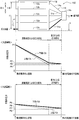
- FIG. 1 It is an explanatory view of a comparative example, the upper figure is a block diagram of a heat exchanger according to the comparative example, and the middle figure is a case where the heat exchanger according to the comparative example functions as a condenser, the flow rate of the refrigerant is relatively large. It is an explanatory view showing change of pressure of a refrigerant in a case, and a lower figure is an explanatory view showing change of pressure of a refrigerant in case flow volume of a refrigerant is comparatively small.
- FIG. 1 is a block diagram of the air conditioner W provided with the outdoor heat exchanger 10t which is a heat exchanger which concerns on 1st Embodiment, and the indoor heat exchanger 10i.
- the air conditioner W is a device that performs air conditioning such as cooling operation and heating operation. As shown in FIG. 1, the air conditioner W includes a refrigerant circuit R, an outdoor fan Ft (fan), and an indoor fan Fi (fan).
- the refrigerant circuit R is a circuit in which a refrigerant circulates in a refrigeration cycle, and includes a compressor G, a four-way valve Vf, an outdoor heat exchanger 10t (heat exchanger), and an indoor heat exchanger 10i (heat exchanger)
- the outdoor expansion valve Vt (expansion valve) and the indoor expansion valve Vi (expansion valve) are provided.
- the refrigerant circuit R includes a compressor G, an outdoor heat exchanger 10t, an outdoor expansion valve Vt, an indoor expansion valve Vi, and an indoor heat exchanger 10i via a four-way valve Vf. It is configured to be sequentially connected in a ring.
- the compressor G is a device that compresses a gaseous refrigerant.
- the type of the compressor G is not particularly limited, and a scroll-type, piston-type, rotary-type, screw-type, centrifugal-type or the like compressor can be used.
- An accumulator (not shown) may be provided on the suction side of the compressor G for gas-liquid separation of the refrigerant.
- the four-way valve Vf is a valve that switches the flow direction of the refrigerant. That is, during the cooling operation (see solid arrows), the discharge side of the compressor G is connected to one end n of the outdoor heat exchanger 10t by the four-way valve Vf, and the suction side of the compressor G is the indoor heat exchanger 10i Is connected to one end u. Thereby, the outdoor heat exchanger 10t functions as a condenser, and the indoor heat exchanger 10i functions as an evaporator.
- the discharge side of the compressor G is connected to one end u of the indoor heat exchanger 10i by the four-way valve Vf, and the suction side of the compressor G is the outdoor heat exchanger 10t Is connected to one end n.
- the indoor heat exchanger 10i functions as a condenser
- the outdoor heat exchanger 10t functions as an evaporator.
- the outdoor heat exchanger 10t is a heat exchanger in which heat exchange is performed between the outside air and the refrigerant.
- the outdoor fan Ft is a fan that sends outside air to the outdoor heat exchanger 10t, and is installed near the outdoor heat exchanger 10t.
- the indoor heat exchanger 10i is a heat exchanger in which heat exchange is performed between indoor air (air in the space to be air-conditioned) and a refrigerant.
- the other end p of the indoor heat exchanger 10i is connected to the other end q of the outdoor heat exchanger 10t through a pipe k.
- the indoor fan Fi is a fan that sends indoor air to the indoor heat exchanger 10i, and is installed near the indoor heat exchanger 10i.
- the outdoor expansion valve Vt is a valve that depressurizes the refrigerant flowing into itself, and is provided in the vicinity of the outdoor heat exchanger 10t in the pipe k.
- the indoor expansion valve Vi is a valve for reducing the pressure of the refrigerant flowing into itself, and is provided in the vicinity of the indoor heat exchanger 10i in the pipe k.
- the compressor G, the four-way valve Vf, the outdoor heat exchanger 10t, the outdoor fan Ft, and the outdoor expansion valve Vt are installed in the outdoor unit Wt. Further, the indoor heat exchanger 10i, the indoor expansion valve Vi, and the indoor fan Fi are installed in the indoor unit Wi. And each apparatus of the air conditioner W is controlled by the control apparatus (not shown) based on the operation signal of each sensor (not shown), a remote control (not shown), etc.
- heat exchangers 10 configurations of the outdoor heat exchanger 10t and the indoor heat exchanger 10i provided in the air conditioner W will be described. Hereinafter, these two heat exchangers will be referred to as “heat exchangers 10”. In addition, since the heat exchanger 10 is installed based on predetermined construction conditions, the "vertical direction" and the “horizontal direction” which are described below should not be interpreted strictly.
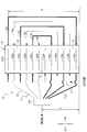
- FIG. 2 is a block diagram of the heat exchanger 10 according to the first embodiment.
- the heat exchanger 10 illustrated in FIG. 2 is a fin-tube type heat exchanger, and includes a first distribution pipe 11, a heat exchange unit 12, connection pipes 13a, 13b,..., 13f, and a second distribution pipe 14. And.
- the first distribution pipe 11 causes the gas refrigerant to be transferred to the upper heat transfer pipes 12Ua, 12Uc, 12Ue and the lower heat transfer pipes 12Db, 12Dd, 12Df as shown by the arrows in FIG. It is piping to distribute.
- the outdoor heat exchanger 10t functions as an evaporator, the gas refrigerants evaporated in the heat exchange unit 12 join in the first distribution pipe 11 in the opposite direction to the arrow in FIG.
- the heat exchange unit 12 shown in FIG. 2 is a structure in which heat exchange between the refrigerant and the air is performed.
- FIG. 3 is explanatory drawing of the heat exchange part 12 and the connection pipe 13a with which the heat exchanger 10 which concerns on 1st Embodiment is equipped.
- the heat exchange unit 12 includes a plurality of fins J, a plurality of upper heat transfer tubes 12Ua and the like (heat transfer tubes), and a plurality of lower heat transfer tubes 12Da and the like (heat transfer tubes).
- the plurality of fins J are metal plates for fixing the positions of the upper heat transfer pipe 12Ua and the lower heat transfer pipe 12Da and promoting heat exchange between the refrigerant and the air.
- the plurality of fins J are arranged such that the plane direction is parallel with a predetermined interval between each other adjacent fin J.
- the plurality of fins J are arranged such that the heat transfer surfaces thereof are parallel to the vertical direction.
- Each of the plurality of fins J has an upper area JU and a lower area JD.
- the upper area JU is an area of the upper portion of the fin J in the vertical direction.
- a plurality of holes (not shown) for penetrating the upper heat transfer pipe 12Ua and the like are formed in the upper region JU.
- the lower region JD is a region under the fin J in the vertical direction.
- a plurality of holes (not shown) for penetrating the lower heat transfer pipe 12Da and the like are formed. The holes are arranged in a line along the vertical direction.
- boundary line Q may be set such that the width in the vertical direction of upper region JU and the width in the vertical direction of lower region JD are substantially equal as shown in FIG. It is not a thing.
- the upper heat transfer pipes 12Ua, 12Ub, ..., 12Uf and the lower heat transfer pipes 12Da, 12Da, 12Db, ..., 12Df shown in Fig. 2 respectively have a refrigerant passing therethrough and a fan (for example, an outdoor fan Ft: It is a metal pipe in which heat exchange with air from 1) takes place.
- the upper heat transfer tubes 12Ua, 12Ub,..., 12Uf penetrate the upper region JU of the fin J.
- the lower heat transfer tubes 12Da, 12Db,..., 12Df penetrate the lower region JD of the fin J.
- 'U' included in the symbols of the upper heat transfer tubes 12Ua, 12Ub,..., 12Uf means being disposed at the upper portion of the heat exchange unit 12.
- “D” included in the reference numerals of the lower heat transfer tubes 12Da, 12Db,..., 12Df means being disposed at the lower part of the heat exchange unit 12.
- 'A' included in the symbols of the upper heat transfer pipe 12Ua and the lower heat transfer pipe 12Da means connected to a connection pipe 13a described later. The same applies to the other upper heat transfer pipes 12Ub, 12Uc, ..., 12Uf and the lower heat transfer pipes 12Db, 12Dc, ..., 12Df.
- upper heat transfer pipes 12Ua, 12Ub, ..., 12Uf and lower heat transfer pipes 12Da, 12Db, ..., 12Df are schematically illustrated in Fig. 2, for example, the upper heat transfer pipes 12Ua are illustrated in Fig. 3. It is configured as shown in. That is, the upper heat transfer pipe 12Ua is disposed such that the refrigerant reciprocates in the fin J in one reciprocation (halfways) in the left-right direction in which the upper heat transfer pipe 12Ua penetrates the fin J. The same applies to the other upper heat transfer pipes 12Ub, 12Uc, ..., 12Uf and the lower heat transfer pipes 12Da, 12Db, ..., 12Df.
- the refrigerant may be guided to the second distribution pipe 14 without reciprocating the refrigerant in the upper heat transfer pipe 12Ua.
- the upper heat transfer pipe 12Ua or the like may be disposed so that the refrigerant reciprocates twice or more in the left-right direction.
- heat transfer pipes having different numbers of reciprocations may be mixed.
- connection pipe 13a shown in FIG. 2 is a pipe that connects the upper heat transfer pipe 12Ua and the lower heat transfer pipe 12Da.
- the refrigerant flowing through the upper heat transfer pipe 12Ua is led to the lower heat transfer pipe 12Da via the connection pipe 13a.
- the connection pipe 13b is a pipe that connects the lower heat transfer pipe 12Db and the upper heat transfer pipe 12Ub.
- the refrigerant flowing through the lower heat transfer pipe 12Db is led to the upper heat transfer pipe 12Ub via the connection pipe 13b.
- the connecting pipe 13a has a height H (a height based on the lower end of the heat exchange portion 12) at the connection position with the upper heat transfer pipe 12Ua, the other connecting pipes 13b, 13c,. It is the highest compared to 13f, while the height of the connection position with the lower heat transfer tube 12Da is the lowest. Further, the height of the connection position of the connection pipe 13b with the upper heat transfer pipe 12Ub is the second highest, while the height of the connection position with the lower heat transfer pipe 12Db is the second lowest. The same applies to the other connection pipes 13c,..., 13f. That is, the height of the connection position with the lower heat transfer pipe is lower as the height of the connection position with the upper heat transfer pipe is higher in the connection pipes 13a, 13b,.
- the height of the connection position with the upper heat transfer tubes 12Ua, 12Ub, ..., 12Uf is the (2n-1) th highest in the upper region JU
- the connection pipes whose heights at the connection positions with the lower heat transfer pipes 12Da, 12Db, ..., 12Df are the (2n-1) th lowest in the lower region JD are arranged to lead the refrigerant from the upper heat transfer pipe to the lower heat transfer pipe It is done.
- 'n' is a natural number.
- the heights of the connection positions with the upper heat transfer tubes 12Ua, 12Ub, ..., 12Uf are the second highest in the upper region JU, and the lower heat transfer tubes 12Da, 12Db,
- the connecting pipe having the 2n-th lowest height in the lower region JD is arranged to lead the refrigerant from the lower heat transfer pipe to the upper heat transfer pipe.
- the refrigerant is transferred from one of the upper heat transfer pipe and the lower heat transfer pipe to the other (for example, from the upper heat transfer pipe 12Ua to the lower heat transfer pipe 12Da) via the connection pipe (for example, the connection pipe 13a) Are configured to be guided.
- the second distribution pipe 14 shown in FIG. 2 causes the liquid refrigerant condensed in the heat exchange unit 12 to merge at the connection unit 14s as shown by the arrow in FIG. Piping.
- the heat exchanger 10 functions as an evaporator
- the upper heat transfer pipes 12Ub, 12Ud, 12Uf and the lower heat transfer pipes 12Da, 12Dc via the second distribution pipe 14 in the direction opposite to the arrow in FIG. , 12De are distributed gas-liquid two-phase refrigerant.
- the height based on the lower end of the heat exchanger 10 of the connection portion 14s of the second distribution pipe 14 is h.
- the upper diagram in FIG. 12 is a configuration diagram of a heat exchanger 10Z according to a comparative example.
- the refrigerant flowing through the heat transfer tube 12a having the highest height is led to the connection 14s via the upper path 14a having the highest height.
- the refrigerant flowing through the heat transfer tube 12e having the lowest height is led to the connection 14s via the lower path 14e having the lowest height. That is, in the heat exchanger 10Z according to the comparative example, the order of the heights of the heat transfer pipes 12a, 12b, ..., 12e through which the refrigerant flows, and the paths 14a, 14b, through which the refrigerant flows through the second distribution pipe 14.
- the order of the height of ..., 14e is the same.
- the explanatory view of ⁇ at a large flow rate> shown in FIG. 12 is an explanatory view showing a change in pressure of the refrigerant when the flow rate of the refrigerant is relatively large when the heat exchanger 10Z according to the comparative example functions as a condenser. is there.
- the horizontal axis of this explanatory view indicates the position in the horizontal direction (left and right direction) of the heat exchanger 10Z, and the vertical axis indicates the pressure of the refrigerant. That is, in the case where the heat exchanger 10Z functions as a condenser, this explanatory view shows the change in the pressure of the refrigerant from the upstream end of the heat exchange unit 12 to the downstream end of the second distribution pipe 14.
- the thin line of the graph of ⁇ at large flow rate> shown in FIG. 12 shows a change in pressure of the refrigerant flowing through the heat transfer pipe 12a and the upper path 14a having the highest height.
- the thick line in the graph indicates the pressure change of the refrigerant flowing through the heat transfer tube 12e having the lowest height and the lower path 14e.
- the upstream end of the heat transfer pipe 12a (the upstream end of the heat exchange unit 12) with the highest height and the upstream end of the heat transfer pipe 12e with the lowest height ( At the upstream end of the heat exchange unit 12, the pressure of the refrigerant is substantially equal. Further, since the refrigerant merges at the downstream end of the second distribution pipe 14, the pressure of the refrigerant at the downstream end of the upper path 14a and the pressure of the refrigerant at the downstream end of the lower path 14e are equal.
- the flow resistance is relatively large when the refrigerant flows through the heat transfer tubes 12a, 12b, ..., 12e at a large flow rate, the refrigerant flowing through the upper heat transfer tube 12a and the lower heat transfer tube 12e The pressure of any of the flowing refrigerants is greatly reduced (pressure change due to flow resistance).
- the pressure of the refrigerant which descends via the upper path 14a rises due to the influence of gravity, and the pressure of the refrigerant which rises via the lower path 14e falls due to the influence of gravity (pressure change due to gravity).
- the pressure decrease width (P1) due to flow resistance is higher than the pressure increase width (P3-P4) due to gravity.
- -P4 is overwhelmingly larger. Further, the same can be said for the pressure change of the refrigerant flowing through the heat transfer tube 12e and the lower path 14e having the lowest height.
- the diagram of ⁇ at a low flow rate> shown in FIG. 12 is an explanatory view showing a change in pressure of the refrigerant when the flow rate of the refrigerant is relatively small when the heat exchanger 10Z according to the comparative example functions as a condenser. .
- the flow resistance when the refrigerant flows through the heat transfer pipes 12a, 12b, ..., 12e becomes smaller than that when the flow rate is large.
- the pressure decrease width due to flow resistance (P5 to P8) is smaller than the pressure increase width due to gravity (P7 to P8) -P7) is not so big. Further, the same can be said for the pressure change of the refrigerant flowing through the heat transfer tube 12e and the lower path 14e having the lowest height.
- the pressure difference ⁇ p (uppermost stage) due to the influence of the gravity of the refrigerant flowing through the uppermost stage is represented by the following formula (1).
- V V is the density of the gas refrigerant
- ⁇ L is the density of the liquid refrigerant
- g is the gravitational acceleration
- H is the height of the heat transfer pipe 12 a relative to the lower end of the heat exchange portion 12
- h is the height of the connection portion 14 s of the second distribution pipe 14.
- ⁇ p (uppermost stage) ⁇ ⁇ V ⁇ g ⁇ H + L L ⁇ g ⁇ (H ⁇ h) (1)
- the first term of the equation (1) represents the pressure drop when the gas refrigerant rises via the first distribution pipe 11.
- the second term of the equation (1) represents the pressure rise when the liquid refrigerant descends through the upper path 14a.
- ⁇ p (bottom stage) ⁇ - L ⁇ g ⁇ h (2)
- Formula (2) represents the pressure drop when the liquid refrigerant moves up and down through the lower path 14e.
- the height of the lower path of the first distribution pipe 11 is substantially zero, there is almost no pressure change when the refrigerant flows through the lower path.
- the difference ⁇ p (comparative example) between the equation (1) and the equation (2) described above is expressed by the following equation (3).
- Formula (3) represents the difference of the influence of gravity in the refrigerant flowing through the top stage and the refrigerant flowing through the bottom stage. Since ⁇ ⁇ V ⁇ ⁇ L , in the equation (3), approximation of ( ⁇ L ⁇ V ) ⁇ L L is performed. Incidentally, in the configuration of the heat exchanger 10Z of the comparative example, even if the height of the connection portion 14s is changed, the above-mentioned pressure difference ⁇ p (comparative example) hardly changes.
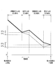
- FIG. 4 is an explanatory view showing a change in pressure when the flow rate of the refrigerant refrigerant is relatively small when the heat exchanger 10 according to the first embodiment functions as a condenser.
- the horizontal axis in FIG. 4 indicates the position in the horizontal direction (left and right direction) of the heat exchanger 10 (see FIG. 2), and the vertical axis indicates the pressure of the refrigerant. That is, in the case where the heat exchanger 10 functions as a condenser, this explanatory view shows the change of the pressure of the refrigerant from the upstream end of the heat exchange unit 12 to the downstream end of the second distribution pipe 14.
- the thick lines in the graph shown in FIG. 4 indicate changes in the pressure of the refrigerant flowing sequentially through the upper heat transfer pipe 12Ua, the connection pipe 13a, the lower heat transfer pipe 12Da, and the lower path 14a of the second distribution pipe 14 shown in FIG. ing.
- thin lines in the graph show changes in pressure of the refrigerant that sequentially flows through the lower heat transfer pipe 12Db, the connection pipe 13b, the upper heat transfer pipe 12Ub, and the upper path 14b of the second distribution pipe 14.
- the pressure difference ⁇ p (uppermost stage) due to the influence of gravity is expressed by the following equation (4).
- M M is the density of the gas-liquid two-phase refrigerant flowing through the connection pipe 13a.
- ⁇ p (uppermost stage) -V V ⁇ g ⁇ H + M M ⁇ g ⁇ H- L L ⁇ g ⁇ h (4)
- the first term of the equation (4) represents the pressure drop when the gas refrigerant rises via the first distribution pipe 11.
- the second term of the equation (4) represents the pressure rise when the gas-liquid two-phase refrigerant descends via the connection pipe 13a.
- the pressure rise in the connection pipe 13a is one of the main features of the present embodiment.
- the third term of the equation (4) represents the pressure drop when the liquid refrigerant rises through the lower path 14 a of the second distribution pipe 14.
- the pressure difference ⁇ p (lowermost stage) due to the influence of gravity is expressed by the following equation (5).
- the height of the heat transfer tube 12Ub shown in FIG. 2 is slightly lower than the height H of the uppermost heat transfer tube 12Ua, in the equation (5), the height of the heat transfer tube 12Ub is H (approximated Yes).
- ⁇ p (lowermost stage) ⁇ ⁇ M ⁇ g ⁇ H + ⁇ L ⁇ g ⁇ (H ⁇ h) (5)
- the first term of the equation (5) represents the pressure drop when the gas-liquid two-phase refrigerant rises via the connection pipe 13b.
- the pressure drop in the connection pipe 13b is one of the main features of the present embodiment.
- the second term of the equation (5) represents the pressure rise when the liquid refrigerant descends via the upper path 14 b of the second distribution pipe 14.
- the difference ⁇ p (in the present embodiment) between the above-mentioned equation (4) and the equation (5) is expressed by the following equation (6).
- Formula (6) represents the difference of the influence of gravity in the refrigerant flowing through the uppermost stage and the refrigerant flowing through the lowermost stage. Since ⁇ ⁇ V ⁇ ⁇ L , in Equation (6), approximation is performed as (2 M M- L L- V V ) ((2 M M- L L ). Further, the magnitude relationship between the densities V v , M M and L L is expressed by the following equation (7).
- the pressure drop of the refrigerant rising in the second distribution pipe 14 is caused by the pressure rise (pressure difference ⁇ p ⁇ shown in FIG. 4) of the refrigerant falling in the connection pipe 13a. At least a part of the pressure difference ⁇ p ⁇ ) is canceled out.
- at least one of the pressure rise (pressure difference ⁇ p ⁇ shown in FIG. 4) of the refrigerant falling in the second distribution pipe 14 due to the pressure drop (pressure difference ⁇ p ⁇ shown in FIG. 4) of the refrigerant rising the connection pipe 13b. Department is canceled. Therefore, according to the present embodiment, the pressure difference ⁇ p (present embodiment) due to the influence of gravity can be made smaller than that of the comparative example.
- the refrigerant is distributed substantially equally to the upper heat transfer pipes 12Ua, 12Ub,... 12Uf and the lower heat transfer pipes 12Da, 12Db,. Accordingly, liquid accumulation in the lower heat transfer pipes 12Da, 12Db and the like can be suppressed, and the heat exchange in the heat exchange section 12 can be made more efficient. In particular, even when the air conditioner W performs low load operation and the flow rate of the refrigerant in the heat exchanger 10 is relatively small, the above-described liquid accumulation can be suppressed.
- the high temperature gas refrigerant is distributed to both the upper and lower portions of the heat exchange unit 12, and the relatively low temperature gas-liquid two-phase refrigerant is connected to the connecting pipes 13a, 13b,. It distributes to both the upper part and the lower part of the heat exchange part 12 via. Therefore, compared with the structure which temperature distribution of a heat exchanger has deviated in the perpendicular direction like above-mentioned patent document 1, the efficiency improvement of heat exchange in the heat exchange part 12 can be achieved.
- the heat transfer pipes 12Ug and 12Ug connected via the connection pipe 13g are adjacent to each other in the vertical direction. It differs from one embodiment. The other aspects are the same as in the first embodiment. Therefore, only the parts different from the first embodiment will be described, and the descriptions of the overlapping parts will be omitted.
- FIG. 5 is a block diagram of a heat exchanger 10A according to the second embodiment.
- the fins J of the heat exchange unit 12 have an intermediate region JM in the vertical direction.
- the middle region JM is a region including the lower portion of the upper region JU of the fin J and the upper portion of the lower region JD.
- the upper heat transfer pipes 12Ug and 12Ug, the lower heat transfer pipes 12Di and 12Di, and the like penetrate the intermediate region JM.
- the upper upper heat transfer pipe 12Ug is connected to the lower upper heat transfer pipe 12Ug adjacent in the vertical direction via a connection pipe 13g.
- the refrigerant is led from the upper heat transfer pipe 12Ua to the lower heat transfer pipe 12Da via the connection pipe 13a, and the lower heat transfer pipe 12Db
- the refrigerant is led to the upper heat transfer pipe 12Ub from the above through the connection pipe 13b.
- the third embodiment is different from the first embodiment in the connection positions of the connection pipes 13j, 13k and the like (see FIG. 6), but the other is the same as the first embodiment. Therefore, only the parts different from the first embodiment will be described, and the descriptions of the overlapping parts will be omitted.
- FIG. 6 is a block diagram of a heat exchanger 10B according to a third embodiment.
- Connection tube 13j shown in FIG. 6 has the highest height in the upper region JU at the connection position with the upper heat transfer tube 12Uj, and has the second highest height in the lower region JD with the connection position with the lower heat transfer tube 12Dj. .
- the refrigerant is led from the upper heat transfer pipe 12Uj to the lower heat transfer pipe 12Dj via the connection pipe 13j.
- Connection tube 13k shown in FIG. 6 is the third highest in connection position with upper heat transfer tube 12Uk in upper region JU, and fourth in the lower region JD in connection position with lower heat transfer tube 12Dk. High.
- the refrigerant is led from the upper heat transfer pipe 12Uk to the lower heat transfer pipe 12Dk via the connection pipe 13k. The same applies to the other connection pipes 13m.
- the heat exchange unit 12 functions as a condenser
- the heights of the connection positions with the upper heat transfer tubes 12Uj, 12Uk, 12Um are the (2n-1) th highest in the upper region JU
- the lower heat transfer tubes 12Dj, 12Dk , 12Dm are led from the upper heat transfer pipe to the lower heat transfer pipe via the 2n-th highest connection pipe in the lower region JD.
- 'n' is a natural number.
- Connection tube 13q shown in FIG. 6 has the second highest height in the upper region JU at the connection position with the upper heat transfer tube 12Uq, and the highest in the lower region JD at the connection position with the lower heat transfer tube 12Dq. .
- the refrigerant is led from the lower heat transfer pipe 12Dq to the upper heat transfer pipe 12Uq via the connection pipe 13q.
- Connection tube 13p shown in FIG. 6 is the fourth highest in connection position with upper heat transfer tube 12Up in upper region JU, and third in the lower region JD in connection position with lower heat transfer tube 12Dp. High.
- the refrigerant is led from the lower heat transfer pipe 12Dp to the upper heat transfer pipe 12Up via the connection pipe 13p. The same applies to the other connection pipes 13n.
- the heights of the connection positions with upper heat transfer tubes 12Uq, 12Up, 12Un are 2n-th highest in upper region JU, and lower heat transfer tubes 12Dq, 12Dp, 12Dn
- the refrigerant is led from the lower heat transfer pipe to the upper heat transfer pipe via the (2n-1) th highest connection pipe in the lower region JD at the height of the connection position.
- the lengths of the connection pipes 13j, 13k,..., 13q can be made shorter than the connection pipes 13a, 13b (see FIG. 2) described in the first embodiment.
- the connection pipes 13j, 13k,..., 13q are smaller than that of the connection pipes 13a, 13b of the first embodiment, the refrigerant easily flows.
- the liquid accumulation in the lower part of the heat exchange part 12 can be suppressed, and the efficiency of heat exchange can be raised.
- the fourth embodiment two rows of holes arranged in the vertical direction are provided in the fin J (see FIG. 7), and the upper heat transfer pipe 12Ua, the lower heat transfer pipe 12Da, and the like pass through these holes. It differs from the first embodiment. Further, the first embodiment is that the refrigerant flowing through the upper heat transfer tube 12Ua in the rear row is led to the lower heat transfer tube 12Da in the front row, and the refrigerant flowing through the lower heat transfer tube 12Db in the rear row is guided to the upper heat transfer tube 12Ub in the front row. It is different from The other aspects are the same as in the first embodiment. Therefore, only the parts different from the first embodiment will be described, and the description of the overlapping parts will be omitted.
- FIG. 7 is a block diagram of a heat exchanger 10C according to the fourth embodiment.
- connection pipes 13a and 13b for guiding the refrigerant from one of the uppermost stage and the lowermost stage to the other are illustrated, and other connection pipes (corresponding to the connection pipes 13c, 13d, 13e and 13f shown in FIG. 2) are shown. Illustration is omitted.
- the heat exchange part 12C functions as a condenser, the flow direction of the refrigerant
- coolant is shown by the arrow.
- a fan F for sending air toward the heat exchange portion 12C is installed.
- two rows of holes (not shown) arranged in the vertical direction are respectively provided. Of the two rows described above, the row on the fan F side (upstream side in the air flow direction) is referred to as the “front row”, and the row on the opposite side (downstream side in the air flow direction) to the fan F It is called "the back row”.
- the upper heat transfer pipes 12Ua and the like pass through the holes in the rear row of the upper area JU, and the upper heat transfer pipes 12Ub and the like pass through the holes in the front line of the upper area JU.
- Lower heat transfer pipes 12Da and the like pass through holes in the front row of the lower region JD, and lower heat transfer pipes 12Db and the like pass through holes in the rear row of the lower region JD.
- connection pipe 13a is a pipe that leads the refrigerant flowing through the upper heat transfer pipe 12Ua to the lower heat transfer pipe 12Da. That is, when the heat exchange unit 12C functions as a condenser, the refrigerant flowing through the upper heat transfer pipe 12Ua in the rear row is led to the lower heat transfer pipe 12Da in the front row via the connection pipe 13a.
- the connection pipe 13b is a pipe that leads the refrigerant flowing through the lower heat transfer pipe 12Db to the upper heat transfer pipe 12Ub. That is, when the heat exchange section 12C functions as a condenser, the refrigerant flowing through the lower heat transfer pipe 12Db in the rear row is led to the upper heat transfer pipe 12Ub in the front row via the connection pipe 13b.
- relatively high temperature gas refrigerant flows through the upper heat transfer pipe 12Ua and the lower heat transfer pipe 12Db in the rear row, and a relatively low temperature gas-liquid two-phase flow in the upper heat transfer pipe 12Ub and the lower heat transfer pipe 12Da in the front row.
- the refrigerant flows. That is, the air heat-exchanged with the relatively low temperature gas-liquid two-phase refrigerant in the front row goes to the rear row, and exchanges heat with the relatively high temperature gas refrigerant in the rear row.
- heat exchange between the refrigerant and the air can be performed with high efficiency by making the temperature distribution of the refrigerant and the flow direction of the air into the counterflow type.
- connection pipes other than the connection pipes 13a and 13b are also disposed so as to guide the refrigerant from one of the upper heat transfer pipe and the lower heat transfer pipe to the other.
- the heights of the connection positions of the lower heat transfer pipes 12Da, 12Db,... are lower as the heights of the connection positions of the connection pipes 13a, 13b, ... with the upper heat transfer pipes 12Ua, 12Ub,.
- liquid accumulation in the lower heat transfer pipes 12Da, 12Db and the like can be prevented, and high efficiency of heat exchange can be achieved.
- the fifth embodiment is different from the fourth embodiment in that the refrigerant flowing through the upper heat transfer pipe 12Ua (see FIG. 8) in the rear row is led to the connection pipe 13a via the upper heat transfer pipe 12Ua in the front row. ing.
- the refrigerant flowing through the lower heat transfer pipe 12Db (see FIG. 8) in the rear row is led to the connection pipe 13b via the lower heat transfer pipe 12Db in the front row, and the fourth embodiment Are different.
- the other aspects are the same as in the fourth embodiment. Therefore, the parts different from the fourth embodiment will be described, and the descriptions of the overlapping parts will be omitted.
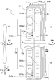
- FIG. 8 is a block diagram of a heat exchanger 10D according to the fifth embodiment.
- connection pipes 13 a and 13 b for guiding the refrigerant from one of the uppermost stage and the lowermost stage to the other are illustrated, and the other connection pipes are not illustrated.
- the fin J shown in FIG. 8 is provided with a plurality of holes (not shown) arranged in the vertical direction in two rows.
- the upper heat transfer tubes 12Ua, 12Ub, etc. pass through the holes of the upper region JU.
- the lower heat transfer tubes 12Da, 12Db, etc. pass through the holes in the lower region JD.
- the heat exchange unit 12D functions as a condenser
- the refrigerant flowing through the upper heat transfer pipe 12Ua in the rear row is led to the upper heat transfer pipe 12Ua in the front row, and then through the connection pipe 13a.
- the heat exchanger 10D is configured to be guided to the lower heat transfer tubes 12Da in the front row.
- the heat exchange unit 12D functions as a condenser
- the refrigerant flowing through the lower heat transfer pipe 12Db in the rear row is led to the lower heat transfer pipe 12Db in the front row, and then the upper portion of the front row is connected via the connection pipe 13b.
- the heat exchanger 10D is configured to be led to the heat transfer tube 12Ub.
- the density M M of the gas-liquid two-phase refrigerant is the density of the liquid refrigerant If it is close to 1 ⁇ 2 of ⁇ L (that is, if the pressure difference ⁇ p in equation (6) approaches zero), the heat exchange can be made more efficient.
- the density M M of the gas-liquid two-phase refrigerant flowing through the connection pipes 13a, 13b, ... is increased to be close to 1 ⁇ 2 of the density L L of the liquid refrigerant,
- the influence of gravity when the refrigerant is distributed to the upper heat transfer tube 12Ua, the lower heat transfer tube 12Da, and the like can be reduced.
- the flow rates of the refrigerant flowing through the upper heat transfer pipe 12Ua, the lower heat transfer pipe 12Da, and the like become substantially equal, and therefore, it is possible to achieve high efficiency of heat exchange in the heat exchanger 10D.
- the sixth embodiment is different from the fourth embodiment in that the refrigerant is guided to the lower heat transfer pipe 12Da in the rear row via the connection pipe 13a (see FIG. 9) and is further guided to the lower heat transfer pipe 12Da in the front row. There is. Further, the sixth embodiment is different from the fourth embodiment in that the refrigerant is led to the upper heat transfer pipe 12Ub in the rear row via the connection pipe 13b (see FIG. 9) and is further led to the upper heat transfer pipe 12Ub in the front row. There is.
- the other aspects are the same as in the fourth embodiment. Therefore, the parts different from the fourth embodiment will be described, and the descriptions of the overlapping parts will be omitted.
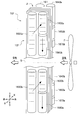
- FIG. 9 is a configuration diagram of a heat exchanger 10E according to a sixth embodiment.
- connection pipes 13a and 13b for guiding the refrigerant from one of the uppermost stage and the lowermost stage to the other are illustrated, and the other connection pipes are not shown.
- the fin J shown in FIG. 9 is provided with a plurality of holes (not shown) arranged in the vertical direction in two rows.
- the upper heat transfer tubes 12Ua, 12Ub, etc. pass through the holes of the upper region JU.
- the lower heat transfer tubes 12Da, 12Db, etc. pass through the holes in the lower region JD.
- the heat exchange unit 12E functions as a condenser
- the refrigerant flowing through the upper heat transfer pipe 12Ua in the rear row is led to the lower heat transfer pipe 12Da in the rear row via the connection pipe 13a.
- the heat exchanger 10E is configured to be led to the lower heat transfer pipe 12Da in the front row afterward.
- the refrigerant flowing through the lower heat transfer pipe 12Db in the rear row is led to the upper heat transfer pipe 12Ub in the rear row via the connection pipe 13b, and then the upper portion in the front row
- the heat exchanger 10E is configured to be led to the heat transfer tube 12Ub.
- the density M M of the gas-liquid two-phase refrigerant is 1 of the density L L of the liquid refrigerant If it becomes equal to / 2, pressure difference (DELTA) p of above-mentioned Formula (6) can be made into zero. This can reduce the influence of gravity when the refrigerant is distributed to the upper heat transfer pipe 12Ua, the lower heat transfer pipe 12Da, and the like.
- the density ⁇ M of the gas-liquid two-phase refrigerant flowing through the connection pipes 13a, 13b, ... is reduced to be close to 1 ⁇ 2 of the density L L of the liquid refrigerant,
- the influence of gravity when the refrigerant is distributed to the upper heat transfer tube 12Ua, the lower heat transfer tube 12Da, and the like can be reduced.
- the flow rates of the refrigerant flowing through the upper heat transfer pipe 12Ua, the lower heat transfer pipe 12Da, and the like become substantially equal, and therefore, the heat exchange efficiency in the heat exchanger 10E can be improved.
- the seventh embodiment is different from the first embodiment in that the heat exchange unit 12F allows the refrigerant to flow through the flat porous pipe 15 (a porous pipe: see FIG. 7).
- the other aspects are the same as in the first embodiment. Therefore, only the parts different from the first embodiment will be described, and the descriptions of the overlapping parts will be omitted.
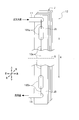
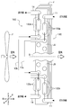
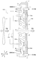
- FIG. 10 is a front view of a heat exchanger 10F according to a seventh embodiment.
- the heat exchange part 12F functions as a condenser
- the solid line arrow shown in FIG. 10 shows the flow path of the refrigerant in the front side
- the broken line arrow shows the flow path of the refrigerant in the back side (refer FIG. 11). It shows.
- connection pipes 13a and 13b for guiding the refrigerant from one of the upper portion and the lower portion of the heat exchange portion 12F to the other are illustrated, and the other connection pipes are not illustrated.
- the heat exchanger 10F includes a heat exchange portion 12F, header pipes 161, 162Ua, 162Db, etc., and connection pipes 13a, 13b,.
- the heat exchange unit 12F includes a plurality of fins J and a plurality of flat porous tubes 15.
- the plurality of fins J are arranged such that the plane direction is parallel with a predetermined interval between each other adjacent fin J.
- the plurality of fins J are arranged such that the heat transfer surfaces thereof are parallel to the vertical direction.
- a plurality of holes for penetrating the flat porous tube 15 (porous tube) are respectively formed.
- the flat porous pipe 15 is a heat transfer pipe in which heat exchange between the refrigerant flowing through the inside thereof and the air from the fan F is performed, and the fin J is penetrated.
- the flat porous tube 15 has a configuration in which a plurality of holes are arranged in the horizontal direction, and exhibits a flat shape (a rectangular shape elongated in the horizontal direction in a cross sectional view). As shown in FIG. 10, in the front row on the fan F side, the plurality of flat porous tubes 15 are arranged in the vertical direction, and in the rear row opposite to the fan F, the plurality of flat porous tubes 15 are in the vertical direction Are arranged in
- the plurality of flat porous tubes 15 penetrating the upper region JU of the fins J correspond to "upper heat transfer tubes”.
- the plurality of flat porous tubes 15 penetrating the lower region JD of the fin J correspond to "lower heat transfer tubes”.
- the header pipe 161 is a pipe for distributing the gas refrigerant flowing into itself to the flat porous pipes 15 in the rear row.
- a part of the refrigerant led to each flat porous pipe 15 in the rear row through the header pipe 161 is directed to the header pipe 162Ua in the rear row through each flat porous pipe 15 in the upper region JU, and the remaining refrigerant is It goes to the header pipe 162Db (refer to FIG. 11) in the rear row through each flat porous pipe 15 in the area JD.
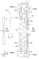
- FIG. 11 is a rear view of the heat exchanger 10F according to the seventh embodiment.
- the refrigerant flowing through the header pipe 162Ua in the rear row is led to the header pipe 163Ua in the front row via piping (not shown), and further, the header pipe in the front row of the upper region JU via the five flat porous pipes 15 It is led to 164Ua.
- the refrigerant flowing through the header pipe 164Ua is lowered via the connection pipe 13a and is led to the header pipe 165Da of the front row of the lower region JD.
- the refrigerant flowing through the header pipe 165Da is led to the header pipe 166Da shown in FIG. 11 through the three flat porous pipes 15. Then, the refrigerant flowing through the header pipe 166Da flows out as a liquid refrigerant via the two flat porous pipes 15 and the header pipe 167Da in the lower region JD shown in FIG.
- the refrigerant flowing through the header pipe 162Db (see FIG. 11) in the rear row is led to the header pipe 163Db in the front row via a pipe (not shown), and further, the lower portion via the five flat porous pipes 15. It is led to the header pipe 164Db of the front row of the area JD. As shown in FIG. 10, the refrigerant flowing through the header pipe 164Db rises via the connection pipe 13b and is led to the header pipe 165Ub in the front row of the upper region JU. The refrigerant flowing through the header pipe 165Ub is led to the header pipe 166Ub shown in FIG. 11 through the three flat porous pipes 15. Then, the refrigerant flowing through the header pipe 166Ub flows out as liquid refrigerant via the two flat porous pipes 15 and the header pipe 167Ub of the upper region JU shown in FIG.
- connection pipes other than the connection pipes 13a and 13b are also arranged to lead the refrigerant from one of the upper heat transfer pipe and the lower heat transfer pipe to the other. Further, as the heights of the connection positions of the connection pipes 13a, 13b, ... with the header pipes 164Ua, 165Ub, ... provided in the upper area JU increase, the header pipes 165Da, 164Db, ... provided in the lower area JD. The height of the connection position with is lowered. By this, the liquid accumulation in the lower part of the heat exchange part 12F can be prevented, and high efficiency-ization of heat exchange can be achieved.
- the refrigerant flowing through the flat porous pipe 15 in the upper area JU is led to the flat porous pipe 15 in the lower area JD via the connection pipe 13a and the like. Further, the refrigerant flowing through the flat porous pipe 15 in the lower area JD is led to the flat porous pipe 15 in the upper area JU via the connection pipe 13b and the like.
- the influence of gravity when the refrigerant is distributed to the flat porous tubes 15 can be reduced. Therefore, it is possible to suppress the deviation in the vertical direction of the flow rate of the refrigerant flowing through each flat porous pipe 15, and to achieve high efficiency of heat exchange in the heat exchanger 10F.
- the heat exchanger 10F is configured to include the plurality of flat porous tubes 15, the density M M of the gas-liquid two-phase refrigerant is higher than that of the finned tube type heat exchanger.
- the density M M of the gas-liquid two-phase refrigerant is higher than that of the finned tube type heat exchanger.
- a flat porous pipe is provided which flows through the front row on the fan F side before the refrigerant flows into the connection pipe 13a etc. You can increase the number of fifteen.
- the number of flat porous pipes 15 flowing in the front row on the fan F side may be reduced.
- the height of the connection position with the upper heat transfer tube is 2n-th highest in the upper region JU
- the height of the connection position with the lower heat transfer tube is 2 n-th lowest in the lower region JD via the upper heat transfer tube
- the refrigerant may be led from the lower heat transfer pipe to the lower heat transfer pipe.
- the height of the connection position with the upper heat transfer tube is (2n-1) th highest in the upper region JU
- the height of the connection position with the lower heat transfer tube is (2 n in the lower region JD -1)
- the refrigerant may be led from the lower heat transfer pipe to the upper heat transfer pipe via the lowest connection pipe.
- the fourth embodiment although a plurality of holes arranged in the vertical direction are provided in two rows in the fin J, and the upper heat transfer pipe 12Ua, the lower heat transfer pipe 12Da, etc. are penetrated in these holes. Not exclusively. That is, three or more rows of holes arranged in the vertical direction may be provided in the fin J.
- the refrigerant flowing through the upper heat transfer tube in the rear row (the row opposite to the fan F) is led to the lower heat transfer tube in the front row (the row on the fan F side) through the connection tube
- the refrigerant flowing through the lower row heat transfer tubes in the rear row may be led to the upper heat transfer tube in the front row via the connection tube.
- the air conditioner W (refer FIG. 1) demonstrated the structure provided with the four-way valve Vf in each embodiment, you may abbreviate
- each embodiment demonstrated the structure in which the air conditioner W (refer FIG. 1) was equipped with the outdoor expansion valve Vt and the indoor expansion valve Vi, it does not restrict to this. That is, one expansion valve may be provided between the outdoor heat exchanger 10t and the indoor heat exchanger 10i, or three or more expansion valves connected in series may be provided. In addition, in the configuration including the plurality of expansion valves, a subcooler for increasing the degree of subcooling of the refrigerant may be provided between the expansion valve and another expansion valve.
- both the outdoor heat exchanger 10t (see FIG. 1) and the indoor heat exchanger 10i (see FIG. 1) have the configuration of the heat exchanger 10 shown in FIGS. 2 and 3.
- one of the outdoor heat exchanger 10 t and the indoor heat exchanger 10 i may have the configuration of the heat exchanger 10 shown in FIGS. 2 and 3.
- each embodiment can be combined suitably.
- the flat porous pipe 15 is made to penetrate each hole, and further in the third embodiment
- the connection pipes 13a, 13b,..., 13f may be arranged as described.
- each embodiment can be applied to a multi-type air conditioner in which a plurality of indoor units Wi are connected to one outdoor unit Wt.
- each embodiment can be applied to an air conditioner having a configuration in which a plurality of outdoor units Wt are connected in parallel.
- the air conditioner W described in each of the embodiments may be a packaged air conditioner or a room air conditioner, or may be an integrated air conditioner in which the outdoor unit Wt and the indoor unit Wi are integrated.
- etc., Demonstrated by each embodiment is applicable to a chiller and a refrigerator other than air conditioner W.
- each embodiment is described in detail for easy understanding of the present invention, and the present invention is not necessarily limited to one having all the configurations described. Moreover, it is possible to add, delete, and replace other configurations for part of the configurations of the respective embodiments. Further, the mechanisms and configurations described above indicate what is considered to be necessary for the description, and not all the mechanisms and configurations of the product are necessarily shown.
Landscapes
- Engineering & Computer Science (AREA)
- Physics & Mathematics (AREA)
- Mechanical Engineering (AREA)
- Thermal Sciences (AREA)
- General Engineering & Computer Science (AREA)
- Geometry (AREA)
- Heat-Exchange Devices With Radiators And Conduit Assemblies (AREA)
Priority Applications (1)
| Application Number | Priority Date | Filing Date | Title |
|---|---|---|---|
| CN201780025312.XA CN109073334B (zh) | 2016-04-26 | 2017-03-17 | 换热器以及空调机 |
Applications Claiming Priority (2)
| Application Number | Priority Date | Filing Date | Title |
|---|---|---|---|
| JP2016087815A JP6531063B2 (ja) | 2016-04-26 | 2016-04-26 | 熱交換器及び空気調和機 |
| JP2016-087815 | 2016-04-26 |
Publications (1)
| Publication Number | Publication Date |
|---|---|
| WO2017187840A1 true WO2017187840A1 (ja) | 2017-11-02 |
Family
ID=60161357
Family Applications (1)
| Application Number | Title | Priority Date | Filing Date |
|---|---|---|---|
| PCT/JP2017/011035 Ceased WO2017187840A1 (ja) | 2016-04-26 | 2017-03-17 | 熱交換器及び空気調和機 |
Country Status (4)
| Country | Link |
|---|---|
| JP (1) | JP6531063B2 (enExample) |
| CN (1) | CN109073334B (enExample) |
| TW (1) | TWI634305B (enExample) |
| WO (1) | WO2017187840A1 (enExample) |
Families Citing this family (1)
| Publication number | Priority date | Publication date | Assignee | Title |
|---|---|---|---|---|
| KR20200053137A (ko) * | 2018-11-08 | 2020-05-18 | 엘지전자 주식회사 | 열교환기 및 이를 포함하는 공기조화기 |
Citations (7)
| Publication number | Priority date | Publication date | Assignee | Title |
|---|---|---|---|---|
| US3489209A (en) * | 1968-12-23 | 1970-01-13 | Herbert G Johnson | Heat exchanger having plastic and metal components |
| JP2005083607A (ja) * | 2003-09-05 | 2005-03-31 | Matsushita Electric Ind Co Ltd | 空気調和機の熱交換器 |
| JP2007163013A (ja) * | 2005-12-13 | 2007-06-28 | Mitsubishi Electric Corp | 冷凍サイクル装置 |
| DE202007009383U1 (de) * | 2007-07-02 | 2007-09-06 | Kalor Thermotechnik Gmbh | Heizkörper |
| JP2009063216A (ja) * | 2007-09-06 | 2009-03-26 | Hitachi Appliances Inc | 熱交換器およびそれを用いた空気調和機 |
| KR20120043916A (ko) * | 2010-10-27 | 2012-05-07 | 엘지전자 주식회사 | 열교환 장치 |
| JP2013053812A (ja) * | 2011-09-05 | 2013-03-21 | Sharp Corp | パラレルフロー型熱交換器及びそれを搭載した空気調和機 |
Family Cites Families (12)
| Publication number | Priority date | Publication date | Assignee | Title |
|---|---|---|---|---|
| JPH0835741A (ja) * | 1994-07-22 | 1996-02-06 | Sanyo Electric Co Ltd | 熱交換器 |
| JP3344218B2 (ja) * | 1996-06-17 | 2002-11-11 | 株式会社日立製作所 | 熱交換器 |
| US6142220A (en) * | 1996-10-02 | 2000-11-07 | Matsushita Electric Industrial Co., Ltd. | Finned heat exchanger |
| FR2758876B1 (fr) * | 1997-01-27 | 1999-04-02 | Valeo Thermique Moteur Sa | Condenseur muni d'un reservoir de fluide refrigerant pour circuit de climatisation |
| JP4814907B2 (ja) * | 2008-05-29 | 2011-11-16 | 日立アプライアンス株式会社 | 冷凍サイクル装置 |
| JP4845943B2 (ja) * | 2008-08-26 | 2011-12-28 | 三菱電機株式会社 | フィンチューブ型熱交換器および冷凍サイクル空調装置 |
| JP5716496B2 (ja) * | 2011-03-31 | 2015-05-13 | ダイキン工業株式会社 | 熱交換器および空気調和機 |
| JP5627635B2 (ja) * | 2012-04-26 | 2014-11-19 | 三菱電機株式会社 | 空気調和機 |
| JP2015108495A (ja) * | 2013-12-06 | 2015-06-11 | 株式会社コロナ | 空気調和機 |
| JP6456088B2 (ja) * | 2014-09-29 | 2019-01-23 | 三菱重工サーマルシステムズ株式会社 | 放熱器および冷凍サイクル装置 |
| CN104596155B (zh) * | 2015-01-27 | 2017-11-07 | 珠海格力电器股份有限公司 | 一种翅片换热器及空调器 |
| JP2017036900A (ja) * | 2015-08-13 | 2017-02-16 | 三菱重工業株式会社 | 放熱器およびそれを用いた超臨界圧冷凍サイクル |
-
2016
- 2016-04-26 JP JP2016087815A patent/JP6531063B2/ja active Active
-
2017
- 2017-03-17 WO PCT/JP2017/011035 patent/WO2017187840A1/ja not_active Ceased
- 2017-03-17 CN CN201780025312.XA patent/CN109073334B/zh active Active
- 2017-04-26 TW TW106113970A patent/TWI634305B/zh active
Patent Citations (7)
| Publication number | Priority date | Publication date | Assignee | Title |
|---|---|---|---|---|
| US3489209A (en) * | 1968-12-23 | 1970-01-13 | Herbert G Johnson | Heat exchanger having plastic and metal components |
| JP2005083607A (ja) * | 2003-09-05 | 2005-03-31 | Matsushita Electric Ind Co Ltd | 空気調和機の熱交換器 |
| JP2007163013A (ja) * | 2005-12-13 | 2007-06-28 | Mitsubishi Electric Corp | 冷凍サイクル装置 |
| DE202007009383U1 (de) * | 2007-07-02 | 2007-09-06 | Kalor Thermotechnik Gmbh | Heizkörper |
| JP2009063216A (ja) * | 2007-09-06 | 2009-03-26 | Hitachi Appliances Inc | 熱交換器およびそれを用いた空気調和機 |
| KR20120043916A (ko) * | 2010-10-27 | 2012-05-07 | 엘지전자 주식회사 | 열교환 장치 |
| JP2013053812A (ja) * | 2011-09-05 | 2013-03-21 | Sharp Corp | パラレルフロー型熱交換器及びそれを搭載した空気調和機 |
Also Published As
| Publication number | Publication date |
|---|---|
| TWI634305B (zh) | 2018-09-01 |
| JP2017198367A (ja) | 2017-11-02 |
| CN109073334A (zh) | 2018-12-21 |
| JP6531063B2 (ja) | 2019-06-12 |
| CN109073334B (zh) | 2020-05-12 |
| TW201738524A (zh) | 2017-11-01 |
Similar Documents
| Publication | Publication Date | Title |
|---|---|---|
| CN112204312B (zh) | 空气调节装置的室外机及空气调节装置 | |
| AU2015325721B2 (en) | Heat exchanger and air conditioning apparatus | |
| JP5754490B2 (ja) | 熱交換器および空気調和装置 | |
| CN107003048B (zh) | 空调机 | |
| JP6419882B2 (ja) | 空気調和機 | |
| JP5975971B2 (ja) | 熱交換器及び冷凍サイクル装置 | |
| JP2018162900A (ja) | 熱交換器、および、それを備えた空気調和機 | |
| JP6576577B1 (ja) | 冷媒分配器、熱交換器及び空気調和装置 | |
| WO2018116929A1 (ja) | 熱交換器及び空気調和機 | |
| JP6925393B2 (ja) | 空気調和装置の室外機及び空気調和装置 | |
| JP2018194251A (ja) | 熱交換器 | |
| US12000633B2 (en) | Outdoor unit and air-conditioning apparatus | |
| JP6531063B2 (ja) | 熱交換器及び空気調和機 | |
| JP6458432B2 (ja) | 熱交換器 | |
| JP6169199B2 (ja) | 熱交換器及び冷凍サイクル装置 | |
| WO2022264348A1 (ja) | 熱交換器および冷凍サイクル装置 | |
| JP2020085267A (ja) | 熱交換器 | |
| JP6952797B2 (ja) | 熱交換器および冷凍サイクル装置 | |
| JP2020115070A (ja) | 熱交換器 | |
| JP2020112274A (ja) | 熱交換器 | |
| WO2016092655A1 (ja) | 冷凍サイクル装置 | |
| CN111750573B (zh) | 热交换器分流器 | |
| JP2020085268A (ja) | 熱交換器 | |
| WO2021234961A1 (ja) | 熱交換器、空気調和装置の室外機及び空気調和装置 | |
| JP2020115069A (ja) | 熱交換器 |
Legal Events
| Date | Code | Title | Description |
|---|---|---|---|
| NENP | Non-entry into the national phase |
Ref country code: DE |
|
| 121 | Ep: the epo has been informed by wipo that ep was designated in this application |
Ref document number: 17789129 Country of ref document: EP Kind code of ref document: A1 |
|
| 122 | Ep: pct application non-entry in european phase |
Ref document number: 17789129 Country of ref document: EP Kind code of ref document: A1 |