WO2017187655A1 - 冷凍サイクル装置 - Google Patents
冷凍サイクル装置 Download PDFInfo
- Publication number
- WO2017187655A1 WO2017187655A1 PCT/JP2016/081206 JP2016081206W WO2017187655A1 WO 2017187655 A1 WO2017187655 A1 WO 2017187655A1 JP 2016081206 W JP2016081206 W JP 2016081206W WO 2017187655 A1 WO2017187655 A1 WO 2017187655A1
- Authority
- WO
- WIPO (PCT)
- Prior art keywords
- refrigerant
- heat
- refrigeration cycle
- compressor
- storage member
- Prior art date
- Legal status (The legal status is an assumption and is not a legal conclusion. Google has not performed a legal analysis and makes no representation as to the accuracy of the status listed.)
- Ceased
Links
Images




Classifications
-
- F—MECHANICAL ENGINEERING; LIGHTING; HEATING; WEAPONS; BLASTING
- F25—REFRIGERATION OR COOLING; COMBINED HEATING AND REFRIGERATION SYSTEMS; HEAT PUMP SYSTEMS; MANUFACTURE OR STORAGE OF ICE; LIQUEFACTION SOLIDIFICATION OF GASES
- F25B—REFRIGERATION MACHINES, PLANTS OR SYSTEMS; COMBINED HEATING AND REFRIGERATION SYSTEMS; HEAT PUMP SYSTEMS
- F25B47/00—Arrangements for preventing or removing deposits or corrosion, not provided for in another subclass
- F25B47/02—Defrosting cycles
- F25B47/022—Defrosting cycles hot gas defrosting
-
- B—PERFORMING OPERATIONS; TRANSPORTING
- B60—VEHICLES IN GENERAL
- B60H—ARRANGEMENTS OF HEATING, COOLING, VENTILATING OR OTHER AIR-TREATING DEVICES SPECIALLY ADAPTED FOR PASSENGER OR GOODS SPACES OF VEHICLES
- B60H1/00—Heating, cooling or ventilating devices
- B60H1/00492—Heating, cooling or ventilating devices comprising regenerative heating or cooling means, e.g. heat accumulators
-
- B—PERFORMING OPERATIONS; TRANSPORTING
- B60—VEHICLES IN GENERAL
- B60H—ARRANGEMENTS OF HEATING, COOLING, VENTILATING OR OTHER AIR-TREATING DEVICES SPECIALLY ADAPTED FOR PASSENGER OR GOODS SPACES OF VEHICLES
- B60H1/00—Heating, cooling or ventilating devices
- B60H1/00642—Control systems or circuits; Control members or indication devices for heating, cooling or ventilating devices
- B60H1/00814—Control systems or circuits characterised by their output, for controlling particular components of the heating, cooling or ventilating installation
- B60H1/00878—Control systems or circuits characterised by their output, for controlling particular components of the heating, cooling or ventilating installation the components being temperature regulating devices
- B60H1/00899—Controlling the flow of liquid in a heat pump system
- B60H1/00921—Controlling the flow of liquid in a heat pump system where the flow direction of the refrigerant does not change and there is an extra subcondenser, e.g. in an air duct
-
- C—CHEMISTRY; METALLURGY
- C09—DYES; PAINTS; POLISHES; NATURAL RESINS; ADHESIVES; COMPOSITIONS NOT OTHERWISE PROVIDED FOR; APPLICATIONS OF MATERIALS NOT OTHERWISE PROVIDED FOR
- C09K—MATERIALS FOR MISCELLANEOUS APPLICATIONS, NOT PROVIDED FOR ELSEWHERE
- C09K5/00—Heat-transfer, heat-exchange or heat-storage materials, e.g. refrigerants; Materials for the production of heat or cold by chemical reactions other than by combustion
- C09K5/02—Materials undergoing a change of physical state when used
- C09K5/04—Materials undergoing a change of physical state when used the change of state being from liquid to vapour or vice versa
- C09K5/041—Materials undergoing a change of physical state when used the change of state being from liquid to vapour or vice versa for compression-type refrigeration systems
- C09K5/044—Materials undergoing a change of physical state when used the change of state being from liquid to vapour or vice versa for compression-type refrigeration systems comprising halogenated compounds
- C09K5/045—Materials undergoing a change of physical state when used the change of state being from liquid to vapour or vice versa for compression-type refrigeration systems comprising halogenated compounds containing only fluorine as halogen
-
- F—MECHANICAL ENGINEERING; LIGHTING; HEATING; WEAPONS; BLASTING
- F25—REFRIGERATION OR COOLING; COMBINED HEATING AND REFRIGERATION SYSTEMS; HEAT PUMP SYSTEMS; MANUFACTURE OR STORAGE OF ICE; LIQUEFACTION SOLIDIFICATION OF GASES
- F25B—REFRIGERATION MACHINES, PLANTS OR SYSTEMS; COMBINED HEATING AND REFRIGERATION SYSTEMS; HEAT PUMP SYSTEMS
- F25B41/00—Fluid-circulation arrangements
- F25B41/20—Disposition of valves, e.g. of on-off valves or flow control valves
- F25B41/26—Disposition of valves, e.g. of on-off valves or flow control valves of fluid flow reversing valves
-
- F—MECHANICAL ENGINEERING; LIGHTING; HEATING; WEAPONS; BLASTING
- F25—REFRIGERATION OR COOLING; COMBINED HEATING AND REFRIGERATION SYSTEMS; HEAT PUMP SYSTEMS; MANUFACTURE OR STORAGE OF ICE; LIQUEFACTION SOLIDIFICATION OF GASES
- F25B—REFRIGERATION MACHINES, PLANTS OR SYSTEMS; COMBINED HEATING AND REFRIGERATION SYSTEMS; HEAT PUMP SYSTEMS
- F25B41/00—Fluid-circulation arrangements
- F25B41/30—Expansion means; Dispositions thereof
- F25B41/39—Dispositions with two or more expansion means arranged in series, i.e. multi-stage expansion, on a refrigerant line leading to the same evaporator
-
- F—MECHANICAL ENGINEERING; LIGHTING; HEATING; WEAPONS; BLASTING
- F25—REFRIGERATION OR COOLING; COMBINED HEATING AND REFRIGERATION SYSTEMS; HEAT PUMP SYSTEMS; MANUFACTURE OR STORAGE OF ICE; LIQUEFACTION SOLIDIFICATION OF GASES
- F25B—REFRIGERATION MACHINES, PLANTS OR SYSTEMS; COMBINED HEATING AND REFRIGERATION SYSTEMS; HEAT PUMP SYSTEMS
- F25B47/00—Arrangements for preventing or removing deposits or corrosion, not provided for in another subclass
- F25B47/02—Defrosting cycles
-
- F—MECHANICAL ENGINEERING; LIGHTING; HEATING; WEAPONS; BLASTING
- F25—REFRIGERATION OR COOLING; COMBINED HEATING AND REFRIGERATION SYSTEMS; HEAT PUMP SYSTEMS; MANUFACTURE OR STORAGE OF ICE; LIQUEFACTION SOLIDIFICATION OF GASES
- F25B—REFRIGERATION MACHINES, PLANTS OR SYSTEMS; COMBINED HEATING AND REFRIGERATION SYSTEMS; HEAT PUMP SYSTEMS
- F25B6/00—Compression machines, plants or systems, with several condenser circuits
- F25B6/04—Compression machines, plants or systems, with several condenser circuits arranged in series
-
- F—MECHANICAL ENGINEERING; LIGHTING; HEATING; WEAPONS; BLASTING
- F28—HEAT EXCHANGE IN GENERAL
- F28D—HEAT-EXCHANGE APPARATUS, NOT PROVIDED FOR IN ANOTHER SUBCLASS, IN WHICH THE HEAT-EXCHANGE MEDIA DO NOT COME INTO DIRECT CONTACT
- F28D20/00—Heat storage plants or apparatus in general; Regenerative heat-exchange apparatus not covered by groups F28D17/00 or F28D19/00
- F28D20/003—Heat storage plants or apparatus in general; Regenerative heat-exchange apparatus not covered by groups F28D17/00 or F28D19/00 using thermochemical reactions
-
- F—MECHANICAL ENGINEERING; LIGHTING; HEATING; WEAPONS; BLASTING
- F28—HEAT EXCHANGE IN GENERAL
- F28D—HEAT-EXCHANGE APPARATUS, NOT PROVIDED FOR IN ANOTHER SUBCLASS, IN WHICH THE HEAT-EXCHANGE MEDIA DO NOT COME INTO DIRECT CONTACT
- F28D20/00—Heat storage plants or apparatus in general; Regenerative heat-exchange apparatus not covered by groups F28D17/00 or F28D19/00
- F28D20/0056—Heat storage plants or apparatus in general; Regenerative heat-exchange apparatus not covered by groups F28D17/00 or F28D19/00 using solid heat storage material
-
- F—MECHANICAL ENGINEERING; LIGHTING; HEATING; WEAPONS; BLASTING
- F28—HEAT EXCHANGE IN GENERAL
- F28D—HEAT-EXCHANGE APPARATUS, NOT PROVIDED FOR IN ANOTHER SUBCLASS, IN WHICH THE HEAT-EXCHANGE MEDIA DO NOT COME INTO DIRECT CONTACT
- F28D20/00—Heat storage plants or apparatus in general; Regenerative heat-exchange apparatus not covered by groups F28D17/00 or F28D19/00
- F28D20/02—Heat storage plants or apparatus in general; Regenerative heat-exchange apparatus not covered by groups F28D17/00 or F28D19/00 using latent heat
-
- F—MECHANICAL ENGINEERING; LIGHTING; HEATING; WEAPONS; BLASTING
- F28—HEAT EXCHANGE IN GENERAL
- F28F—DETAILS OF HEAT-EXCHANGE AND HEAT-TRANSFER APPARATUS, OF GENERAL APPLICATION
- F28F3/00—Plate-like or laminated elements; Assemblies of plate-like or laminated elements
- F28F3/08—Elements constructed for building-up into stacks, e.g. capable of being taken apart for cleaning
- F28F3/10—Arrangements for sealing the margins
-
- B—PERFORMING OPERATIONS; TRANSPORTING
- B60—VEHICLES IN GENERAL
- B60H—ARRANGEMENTS OF HEATING, COOLING, VENTILATING OR OTHER AIR-TREATING DEVICES SPECIALLY ADAPTED FOR PASSENGER OR GOODS SPACES OF VEHICLES
- B60H1/00—Heating, cooling or ventilating devices
- B60H1/00642—Control systems or circuits; Control members or indication devices for heating, cooling or ventilating devices
- B60H1/00814—Control systems or circuits characterised by their output, for controlling particular components of the heating, cooling or ventilating installation
- B60H1/00878—Control systems or circuits characterised by their output, for controlling particular components of the heating, cooling or ventilating installation the components being temperature regulating devices
- B60H2001/00935—Control systems or circuits characterised by their output, for controlling particular components of the heating, cooling or ventilating installation the components being temperature regulating devices comprising four way valves for controlling the fluid direction
-
- B—PERFORMING OPERATIONS; TRANSPORTING
- B60—VEHICLES IN GENERAL
- B60H—ARRANGEMENTS OF HEATING, COOLING, VENTILATING OR OTHER AIR-TREATING DEVICES SPECIALLY ADAPTED FOR PASSENGER OR GOODS SPACES OF VEHICLES
- B60H1/00—Heating, cooling or ventilating devices
- B60H1/00642—Control systems or circuits; Control members or indication devices for heating, cooling or ventilating devices
- B60H1/00814—Control systems or circuits characterised by their output, for controlling particular components of the heating, cooling or ventilating installation
- B60H1/00878—Control systems or circuits characterised by their output, for controlling particular components of the heating, cooling or ventilating installation the components being temperature regulating devices
- B60H2001/00961—Control systems or circuits characterised by their output, for controlling particular components of the heating, cooling or ventilating installation the components being temperature regulating devices comprising means for defrosting outside heat exchangers
-
- C—CHEMISTRY; METALLURGY
- C09—DYES; PAINTS; POLISHES; NATURAL RESINS; ADHESIVES; COMPOSITIONS NOT OTHERWISE PROVIDED FOR; APPLICATIONS OF MATERIALS NOT OTHERWISE PROVIDED FOR
- C09K—MATERIALS FOR MISCELLANEOUS APPLICATIONS, NOT PROVIDED FOR ELSEWHERE
- C09K2205/00—Aspects relating to compounds used in compression type refrigeration systems
- C09K2205/10—Components
- C09K2205/12—Hydrocarbons
- C09K2205/126—Unsaturated fluorinated hydrocarbons
-
- F—MECHANICAL ENGINEERING; LIGHTING; HEATING; WEAPONS; BLASTING
- F25—REFRIGERATION OR COOLING; COMBINED HEATING AND REFRIGERATION SYSTEMS; HEAT PUMP SYSTEMS; MANUFACTURE OR STORAGE OF ICE; LIQUEFACTION SOLIDIFICATION OF GASES
- F25B—REFRIGERATION MACHINES, PLANTS OR SYSTEMS; COMBINED HEATING AND REFRIGERATION SYSTEMS; HEAT PUMP SYSTEMS
- F25B2313/00—Compression machines, plants or systems with reversible cycle not otherwise provided for
- F25B2313/021—Indoor unit or outdoor unit with auxiliary heat exchanger not forming part of the indoor or outdoor unit
- F25B2313/0211—Indoor unit or outdoor unit with auxiliary heat exchanger not forming part of the indoor or outdoor unit the auxiliary heat exchanger being only used during defrosting
-
- F—MECHANICAL ENGINEERING; LIGHTING; HEATING; WEAPONS; BLASTING
- F25—REFRIGERATION OR COOLING; COMBINED HEATING AND REFRIGERATION SYSTEMS; HEAT PUMP SYSTEMS; MANUFACTURE OR STORAGE OF ICE; LIQUEFACTION SOLIDIFICATION OF GASES
- F25B—REFRIGERATION MACHINES, PLANTS OR SYSTEMS; COMBINED HEATING AND REFRIGERATION SYSTEMS; HEAT PUMP SYSTEMS
- F25B2339/00—Details of evaporators; Details of condensers
- F25B2339/04—Details of condensers
-
- F—MECHANICAL ENGINEERING; LIGHTING; HEATING; WEAPONS; BLASTING
- F25—REFRIGERATION OR COOLING; COMBINED HEATING AND REFRIGERATION SYSTEMS; HEAT PUMP SYSTEMS; MANUFACTURE OR STORAGE OF ICE; LIQUEFACTION SOLIDIFICATION OF GASES
- F25B—REFRIGERATION MACHINES, PLANTS OR SYSTEMS; COMBINED HEATING AND REFRIGERATION SYSTEMS; HEAT PUMP SYSTEMS
- F25B2339/00—Details of evaporators; Details of condensers
- F25B2339/04—Details of condensers
- F25B2339/042—Details of condensers of pcm condensers
-
- F—MECHANICAL ENGINEERING; LIGHTING; HEATING; WEAPONS; BLASTING
- F25—REFRIGERATION OR COOLING; COMBINED HEATING AND REFRIGERATION SYSTEMS; HEAT PUMP SYSTEMS; MANUFACTURE OR STORAGE OF ICE; LIQUEFACTION SOLIDIFICATION OF GASES
- F25B—REFRIGERATION MACHINES, PLANTS OR SYSTEMS; COMBINED HEATING AND REFRIGERATION SYSTEMS; HEAT PUMP SYSTEMS
- F25B2400/00—Component parts or details not otherwise provided for in this subclass
- F25B2400/04—Refrigeration circuit bypassing means
- F25B2400/0409—Refrigeration circuit bypassing means for evaporators
-
- F—MECHANICAL ENGINEERING; LIGHTING; HEATING; WEAPONS; BLASTING
- F25—REFRIGERATION OR COOLING; COMBINED HEATING AND REFRIGERATION SYSTEMS; HEAT PUMP SYSTEMS; MANUFACTURE OR STORAGE OF ICE; LIQUEFACTION SOLIDIFICATION OF GASES
- F25B—REFRIGERATION MACHINES, PLANTS OR SYSTEMS; COMBINED HEATING AND REFRIGERATION SYSTEMS; HEAT PUMP SYSTEMS
- F25B2400/00—Component parts or details not otherwise provided for in this subclass
- F25B2400/24—Thermal storage element
-
- F—MECHANICAL ENGINEERING; LIGHTING; HEATING; WEAPONS; BLASTING
- F25—REFRIGERATION OR COOLING; COMBINED HEATING AND REFRIGERATION SYSTEMS; HEAT PUMP SYSTEMS; MANUFACTURE OR STORAGE OF ICE; LIQUEFACTION SOLIDIFICATION OF GASES
- F25B—REFRIGERATION MACHINES, PLANTS OR SYSTEMS; COMBINED HEATING AND REFRIGERATION SYSTEMS; HEAT PUMP SYSTEMS
- F25B2500/00—Problems to be solved
- F25B2500/09—Improving heat transfers
-
- F—MECHANICAL ENGINEERING; LIGHTING; HEATING; WEAPONS; BLASTING
- F25—REFRIGERATION OR COOLING; COMBINED HEATING AND REFRIGERATION SYSTEMS; HEAT PUMP SYSTEMS; MANUFACTURE OR STORAGE OF ICE; LIQUEFACTION SOLIDIFICATION OF GASES
- F25B—REFRIGERATION MACHINES, PLANTS OR SYSTEMS; COMBINED HEATING AND REFRIGERATION SYSTEMS; HEAT PUMP SYSTEMS
- F25B2600/00—Control issues
- F25B2600/11—Fan speed control
-
- F—MECHANICAL ENGINEERING; LIGHTING; HEATING; WEAPONS; BLASTING
- F25—REFRIGERATION OR COOLING; COMBINED HEATING AND REFRIGERATION SYSTEMS; HEAT PUMP SYSTEMS; MANUFACTURE OR STORAGE OF ICE; LIQUEFACTION SOLIDIFICATION OF GASES
- F25B—REFRIGERATION MACHINES, PLANTS OR SYSTEMS; COMBINED HEATING AND REFRIGERATION SYSTEMS; HEAT PUMP SYSTEMS
- F25B2600/00—Control issues
- F25B2600/25—Control of valves
- F25B2600/2513—Expansion valves
-
- F—MECHANICAL ENGINEERING; LIGHTING; HEATING; WEAPONS; BLASTING
- F25—REFRIGERATION OR COOLING; COMBINED HEATING AND REFRIGERATION SYSTEMS; HEAT PUMP SYSTEMS; MANUFACTURE OR STORAGE OF ICE; LIQUEFACTION SOLIDIFICATION OF GASES
- F25B—REFRIGERATION MACHINES, PLANTS OR SYSTEMS; COMBINED HEATING AND REFRIGERATION SYSTEMS; HEAT PUMP SYSTEMS
- F25B47/00—Arrangements for preventing or removing deposits or corrosion, not provided for in another subclass
- F25B47/02—Defrosting cycles
- F25B47/022—Defrosting cycles hot gas defrosting
- F25B47/025—Defrosting cycles hot gas defrosting by reversing the cycle
-
- F—MECHANICAL ENGINEERING; LIGHTING; HEATING; WEAPONS; BLASTING
- F25—REFRIGERATION OR COOLING; COMBINED HEATING AND REFRIGERATION SYSTEMS; HEAT PUMP SYSTEMS; MANUFACTURE OR STORAGE OF ICE; LIQUEFACTION SOLIDIFICATION OF GASES
- F25B—REFRIGERATION MACHINES, PLANTS OR SYSTEMS; COMBINED HEATING AND REFRIGERATION SYSTEMS; HEAT PUMP SYSTEMS
- F25B5/00—Compression machines, plants or systems, with several evaporator circuits, e.g. for varying refrigerating capacity
- F25B5/04—Compression machines, plants or systems, with several evaporator circuits, e.g. for varying refrigerating capacity arranged in series
-
- F—MECHANICAL ENGINEERING; LIGHTING; HEATING; WEAPONS; BLASTING
- F28—HEAT EXCHANGE IN GENERAL
- F28D—HEAT-EXCHANGE APPARATUS, NOT PROVIDED FOR IN ANOTHER SUBCLASS, IN WHICH THE HEAT-EXCHANGE MEDIA DO NOT COME INTO DIRECT CONTACT
- F28D20/00—Heat storage plants or apparatus in general; Regenerative heat-exchange apparatus not covered by groups F28D17/00 or F28D19/00
-
- Y—GENERAL TAGGING OF NEW TECHNOLOGICAL DEVELOPMENTS; GENERAL TAGGING OF CROSS-SECTIONAL TECHNOLOGIES SPANNING OVER SEVERAL SECTIONS OF THE IPC; TECHNICAL SUBJECTS COVERED BY FORMER USPC CROSS-REFERENCE ART COLLECTIONS [XRACs] AND DIGESTS
- Y02—TECHNOLOGIES OR APPLICATIONS FOR MITIGATION OR ADAPTATION AGAINST CLIMATE CHANGE
- Y02E—REDUCTION OF GREENHOUSE GAS [GHG] EMISSIONS, RELATED TO ENERGY GENERATION, TRANSMISSION OR DISTRIBUTION
- Y02E60/00—Enabling technologies; Technologies with a potential or indirect contribution to GHG emissions mitigation
- Y02E60/14—Thermal energy storage
-
- Y—GENERAL TAGGING OF NEW TECHNOLOGICAL DEVELOPMENTS; GENERAL TAGGING OF CROSS-SECTIONAL TECHNOLOGIES SPANNING OVER SEVERAL SECTIONS OF THE IPC; TECHNICAL SUBJECTS COVERED BY FORMER USPC CROSS-REFERENCE ART COLLECTIONS [XRACs] AND DIGESTS
- Y02—TECHNOLOGIES OR APPLICATIONS FOR MITIGATION OR ADAPTATION AGAINST CLIMATE CHANGE
- Y02P—CLIMATE CHANGE MITIGATION TECHNOLOGIES IN THE PRODUCTION OR PROCESSING OF GOODS
- Y02P20/00—Technologies relating to chemical industry
- Y02P20/10—Process efficiency
Definitions
- This disclosure relates to a refrigeration cycle apparatus that performs a defrosting operation for defrosting an evaporator when frost is formed.
- Patent Document 1 discloses a refrigeration cycle apparatus that performs a defrosting operation for defrosting an evaporator that evaporates a refrigerant when frosting occurs.
- high temperature refrigerant that is, hot gas
- discharged from the compressor is caused to flow into the evaporator to defrost the evaporator. Is going.
- the refrigeration cycle apparatus that heats the heating target fluid by exchanging heat between the high-temperature refrigerant discharged from the compressor by the radiator and the heating target fluid (for example, blown air blown into the air-conditioning target space), During the frost operation, the heating capacity of the fluid to be heated is reduced.
- the present disclosure aims to suppress an increase in energy consumption of a compressor in a refrigeration cycle apparatus capable of performing a defrosting operation.
- a refrigeration cycle apparatus includes a compressor that compresses and discharges a refrigerant, a radiator that dissipates the refrigerant, a decompression device that depressurizes the refrigerant, and an evaporator that evaporates the refrigerant.
- a compressor that compresses and discharges a refrigerant
- a radiator that dissipates the refrigerant
- a decompression device that depressurizes the refrigerant
- an evaporator that evaporates the refrigerant.
- the refrigeration cycle apparatus includes a solid heat storage member that stores heat of the high-pressure refrigerant that flows through the refrigerant flow path from the discharge side of the compressor to the inlet side of the decompression device during normal operation, and the heat storage member is insulated from the metal. It has a strongly correlated electronic material that stores or dissipates heat by phase change with the body, and heats the evaporator using the heat stored in the heat storage member as a heat source during defrosting operation to remove frost generated in the evaporator .
- the evaporator since the evaporator is heated using the heat stored in the heat storage member as a heat source during the defrosting operation, the evaporator can be defrosted while suppressing an increase in energy consumption of the compressor.
- the heat storage member since a solid member having a strongly correlated electron system material is adopted as the heat storage member, heat storage or heat dissipation necessary for defrosting can be performed in the solid state. Therefore, it is extremely easy to arrange the heat storage member in the refrigeration cycle device as compared with the case of using a heat storage agent that stores or releases heat by phase change between liquid and solid or phase change between gas and solid. it can.
- the transition temperature (phase transition temperature between the metal and the insulator) can be adjusted. Therefore, the transition temperature can be appropriately adjusted in advance according to the temperature range of the refrigerant of the refrigeration cycle apparatus to be applied. Thereby, efficient heat storage or heat dissipation of the heat storage member can be realized.
- FIGS. 1-4 1st Embodiment of this indication is described using FIGS. 1-4.
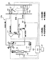
- the refrigeration cycle apparatus 10 shown in the overall configuration diagram of FIG. 1 is applied to a heating apparatus.
- the refrigeration cycle apparatus 10 fulfills the function of heating the air blown into the room, which is the air-conditioning target space, in the heating apparatus. Therefore, the heating target fluid of the refrigeration cycle apparatus 10 is blown air.
- the normal operation heating the blown air and the frost formation on the outdoor heat exchanger 16 that functions as an evaporator are removed.
- Switching between defrosting operation for frosting can be performed. Therefore, in FIG. 1, the refrigerant flow during normal operation is indicated by a white arrow, and the refrigerant flow during defrosting operation is indicated by a black arrow.
- the refrigeration cycle apparatus 10 includes a compressor 11, an indoor radiator 12, a four-way valve 14, an expansion valve 15, an outdoor heat exchanger 16, and the like.
- the compressor 11 sucks, compresses and discharges the refrigerant in the refrigeration cycle apparatus 10.
- the compressor 11 is an electric compressor configured by housing a fixed capacity type compression mechanism and an electric motor for driving the compression mechanism in a housing. The operation (the number of rotations) of the electric motor is controlled by a control signal output from the control device 40 described later.
- the inlet side of the indoor radiator 12 is connected to the discharge port of the compressor 11.
- the indoor radiator 12 is a radiator that heats the blown air by exchanging heat between the refrigerant discharged from the compressor 11 and the blown air blown from the blower 12a during normal operation.
- the blower 12a is an electric blower in which the rotation speed (the amount of blown air) is controlled by a control voltage output from the control device 40.
- the refrigeration cycle apparatus 10 is provided with a bypass passage 13a that guides the refrigerant discharged from the compressor 11 to the refrigerant outlet side of the indoor radiator 12 by bypassing the indoor radiator 12.
- An open / close valve 13 for opening and closing the bypass passage 13a is disposed in the bypass passage 13a.
- the on-off valve 13 is an electromagnetic valve whose operation is controlled by a control signal output from the control device 40.
- the on-off valve 13 constitutes a refrigerant circuit switching device that switches the refrigerant circuit of the refrigeration cycle apparatus 10. More specifically, the on-off valve 13 closes the bypass passage 13a during normal operation and opens the bypass passage 13a during defrosting operation.
- the pressure loss that occurs when the refrigerant passes through the bypass passage 13 a is extremely small compared to the pressure loss that occurs when the refrigerant passes through the indoor radiator 12. For this reason, when the on-off valve 13 opens the bypass passage 13 a, almost the entire flow rate of the refrigerant discharged from the compressor 11 flows through the bypass passage 13 a and is guided to the refrigerant outlet side of the indoor radiator 12.
- the four-way valve 14 is an electric four-way valve whose operation is controlled by a control voltage output from the control device 40.
- the four-way valve 14 and the on-off valve 13 constitute a refrigerant circuit switching device that switches the refrigerant circuit.
- the four-way valve 14 connects the refrigerant outlet side of the indoor radiator 12 and the one inlet / outlet of the expansion valve 15 (that is, the refrigerant inlet during normal operation) and at the same time outdoor heat. It switches to the refrigerant circuit which connects the one refrigerant
- the refrigerant outlet side of the indoor radiator 12 and one refrigerant inlet / outlet side of the outdoor heat exchanger 16 are connected, and at the same time, one inlet / outlet side of the expansion valve 15 and the inlet side of the compressor 11. And switch to the refrigerant circuit to connect.
- the expansion valve 15 includes a variable throttle mechanism having a valve element configured to change the throttle opening degree and an electric actuator including a stepping motor that changes the throttle opening degree by displacing the valve element. It is.
- the operation of the expansion valve 15 is controlled by a control signal (control pulse) output from the control device 40.
- the other refrigerant inlet / outlet side of the outdoor heat exchanger 16 is connected to the other inlet / outlet of the expansion valve 15 (that is, the refrigerant outlet during normal operation).
- the outdoor heat exchanger 16 is an evaporator that evaporates by exchanging heat with the outdoor air (outside air) blown from the blower fan 16a during the normal operation.
- the blower fan 16 a is an electric blower in which the rotation speed (the amount of blown air) is controlled by a control voltage output from the control device 40.
- the heat storage member 17 is disposed in the refrigerant circuit that connects the four-way valve 14 and the expansion valve 15.
- the heat storage member 17 having a strongly correlated electron material is employed.
- the strongly correlated electron material is a substance having a strong effective Coulomb interaction acting between electrons among substances.
- strong correlation electron materials include transition metal oxides, organic ⁇ -electron complexes, and the like.
- metal-insulator transition which is one of the properties of strongly correlated electron materials
- VO 2 vanadium dioxide
- a VO 2 added with an additive is employed.
- the transition metal oxide has a property of changing from an insulator to a metal when heat energy is applied from the outside.
- the effective Coulomb interaction between the outermost shell electrons of the transition metal atom is strong. Therefore, when the temperature is lower than the metal-insulator transition temperature, the outermost electrons are free to move freely. It will be unable to move (insulator). When the transition metal oxide serving as an insulator is given thermal energy from the outside until the temperature exceeds the metal insulator transition temperature, the outermost shell electrons can move freely (metal).
- transition metal oxide stores heat.
- the heat stored at this time is stored when, for example, ice (solid) in which water molecules cannot move freely changes to water (liquid) in which water molecules can move freely. Heat corresponding to latent heat of fusion.
- the transition metal oxide undergoes a phase transition from a metal to an insulator, the stored heat is dissipated.
- the heat stored at this time is, for example, when ice (solid), in which water molecules cannot move freely, changes phase to water (liquid) in which water molecules can move freely.
- This heat is equivalent to the latent heat of fusion that is stored.
- the transition metal oxide undergoes a phase transition from a metal to an insulator, the stored heat is dissipated. Therefore, the transition metal oxide can perform heat storage or heat dissipation by changing the phase between a metal and an insulator.
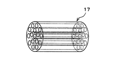
- the heat storage member 17 is formed by forming a transition metal oxide in a columnar shape and forming a plurality of through holes in the axial direction.
- the heat storage member 17 is arranged in the refrigerant pipe connecting the four-way valve 14 and the expansion valve 15 so as to be directly in contact with the refrigerant and capable of heat transfer without being housed in a dedicated container or the like. Yes. Therefore, the heat storage member 17 is disposed in the refrigerant flow path through which the refrigerant in a range from the discharge port side of the compressor 11 to the inlet side of the expansion valve 15 flows during normal operation.
- transition metal oxide phase transition temperature between metal and insulator
- transition temperature of VO 2 is 68 ° C.
- the transition temperature is adjusted to about 20 ° C. to 40 ° C. by adding W (tungsten) to VO 2. Yes.
- the control device 40 is composed of a well-known microcomputer including a CPU, a ROM, a RAM and the like and its peripheral circuits.
- the control device 40 performs various calculations and processes based on the control program stored in the ROM. And the action
- ⁇ A sensor group for air conditioning control such as an inside air temperature sensor, an outside air temperature sensor, and an outdoor unit temperature sensor is connected to the input side of the control device 40, and detection values of these sensor groups are input.
- the inside air temperature sensor is an inside air temperature detecting device that detects the temperature in the room that is the air-conditioning target space.
- the outside air temperature sensor is an outside air temperature detecting device that detects outside air temperature.
- the outdoor temperature sensor is an evaporator temperature detection device that detects the temperature of the outdoor heat exchanger 16 (the refrigerant evaporation temperature in the outdoor heat exchanger 16).
- an operation panel 41 is connected to the input side of the control device 40, and operation signals from various operation switches provided on the operation panel 41 are input to the control device 40.
- various operation switches an operation switch that requires air conditioning (heating in this embodiment), a temperature setting switch that sets a room temperature, and the like are provided.
- control apparatus 40 of this embodiment is comprised integrally, among each control apparatus 40, each control A configuration (hardware and software) for controlling the operation of the target device constitutes a control unit of each control target device.
- the normal operation and the defrosting operation can be switched.
- the normal operation is performed when the operation switch of the operation panel 41 is turned on (ON), and the frost determination unit of the control device 40 determines that frost is not generated in the outdoor heat exchanger 16.
- a frost determination part when the detection value Te of the outdoor unit temperature sensor is lower than the value obtained by subtracting a predetermined reference temperature ⁇ from the detection value Tam of the outside air temperature sensor ( That is, a control program that determines that frost formation has occurred in the outdoor heat exchanger 16 (when Te ⁇ Tam ⁇ ) can be employed.
- control device 40 closes the on-off valve 13 and connects the refrigerant outlet side of the indoor radiator 12 and one inlet / outlet side of the expansion valve 15 and at the same time one refrigerant inlet / outlet side of the outdoor heat exchanger 16. And the operation of the four-way valve 14 is controlled so that the suction port side of the compressor 11 is connected.
- control device 40 responds to the detection signal of the air conditioning control sensor group so that the detected value of the internal air temperature sensor approaches the set temperature set by the temperature setting switch, the compressor 11, the blower 12a, and the expansion.
- the operation of the valve 15 and the blower fan 16a is controlled.
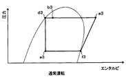
- the refrigerant circuit is switched to the refrigerant circuit through which the refrigerant flows as shown by the white arrow in FIG. That is, switching to the refrigerant circuit in which the refrigerant circulates in the order of the compressor 11 ⁇ indoor radiator 12 ⁇ (four-way valve 14 ⁇ ) heat storage member 17 ⁇ expansion valve 15 ⁇ outdoor heat exchanger 16 ⁇ (four-way valve 14 ⁇ ) compressor 11. It is done. Accordingly, during normal operation, the state of the refrigerant changes as shown in the Mollier diagram of FIG.
- the refrigerant flowing into the indoor radiator 12 radiates heat by exchanging heat with the blown air blown from the blower 12a (point a3 ⁇ b3 in FIG. 3). Thereby, blowing air is heated.
- the high-pressure refrigerant flowing out of the indoor radiator 12 radiates heat to the heat storage member 17 until the temperature of the heat storage member 17 becomes equal to that of the high-pressure refrigerant when flowing through the refrigerant pipe from the four-way valve 14 to the expansion valve 15 (FIG. 3 b3 point ⁇ d3 point).
- the transition metal oxide undergoes a phase transition from the insulator to the metal, thereby storing the heat released from the high-pressure refrigerant.
- the refrigerant flowing into the expansion valve 15 is depressurized until it becomes a low-pressure refrigerant (d3 point ⁇ e3 point in FIG. 3).
- the low-pressure refrigerant decompressed by the expansion valve 15 flows into the outdoor heat exchanger 16.
- the refrigerant flowing into the outdoor heat exchanger 16 absorbs heat from the outside air blown from the blower fan 16a and evaporates (point e3 ⁇ f3 in FIG. 3).
- the low-pressure refrigerant flowing out of the outdoor heat exchanger 16 is sucked into the compressor 11 via the four-way valve 14 and compressed again (point f3 ⁇ a3 in FIG. 3).
- indoor air can be heated by heating the blown air with the indoor radiator 12 and blowing the heated blown air into the room.
- the heat storage member 17 can store heat.
- the defrosting operation is executed until a predetermined defrosting time elapses when the frosting determination unit of the control device 40 determines that the outdoor heat exchanger 16 is frosted during the normal operation. Is done.
- the control device 40 opens the on-off valve 13 to connect the refrigerant outlet side of the indoor radiator 12 and one refrigerant inlet / outlet side of the outdoor heat exchanger 16 and at the same time one inlet / outlet of the expansion valve 15.
- the operation of the four-way valve 14 is controlled so as to connect the side and the suction port side of the compressor 11.
- the control apparatus 40 reduces the refrigerant
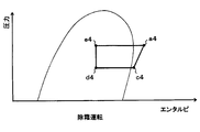
- the refrigerant circuit is switched to the refrigerant circuit through which the refrigerant flows as shown by the black arrow in FIG. That is, the refrigerant circuit is switched to the refrigerant circuit in which the refrigerant circulates in the order of the compressor 11 ⁇ (the bypass passage 13a ⁇ the four-way valve 14) ⁇ the heat storage member 17 ⁇ the expansion valve 15 ⁇ the outdoor heat exchanger 16 ⁇ (the four-way valve 14). . Therefore, during the defrosting operation, the state of the refrigerant changes as shown in the Mollier diagram of FIG.
- the refrigerant discharged from the compressor 11 flows into the outdoor heat exchanger 16 via the bypass passage 13a and the four-way valve 14 because the on-off valve 13 is open. .
- the refrigerant flowing into the outdoor heat exchanger 16 dissipates heat to the outdoor heat exchanger 16 to melt frost (point a4 ⁇ point e4 in FIG. 4).
- frost point a4 ⁇ point e4 in FIG. 4
- the outdoor heat exchanger 16 is defrosted.
- the refrigerant flowing out of the outdoor heat exchanger 16 is depressurized by the expansion valve 15 (point e4 ⁇ point d4 in FIG. 4).
- the refrigerant depressurized by the expansion valve 15 stores heat until the temperature of the heat storage member 17 becomes equal to the refrigerant depressurized by the expansion valve 15 when flowing through the refrigerant piping from the expansion valve 15 to the four-way valve 14.
- the heat stored in the member 17 is absorbed (d4 point ⁇ c4 point in FIG. 4).
- the transition metal oxide undergoes a phase transition from a metal to an insulator, thereby radiating the stored heat.
- the outdoor heat exchanger 16 can be defrosted by heating the outdoor heat exchanger 16 using the heat stored in the heat storage member 17 as a heat source.
- the refrigerant discharge capacity of the compressor 11 is reduced as compared with that during normal operation, and the outdoor heat exchanger 16 is heated using the heat stored in the heat storage member 17 as a heat source.
- the outdoor heat exchanger 16 can be defrosted while suppressing an increase in
- a solid member having a strongly correlated electron material is employed as the heat storage member 17, so that the solid state is changed by the phase change between the metal and the insulator.
- heat storage or heat dissipation necessary for defrosting can be performed. Therefore, compared with the case where a heat storage agent that performs heat storage or heat dissipation by adopting a phase change between a liquid and a solid or a phase change between a gas and a solid is employed, the heat storage member is extremely easily contained in the refrigerant pipe of the refrigeration cycle apparatus 10. 17 can be arranged.
- the heat storage member 17 is disposed in the refrigerant pipe from the discharge port side of the compressor 11 to the inlet side of the expansion valve 15 during normal operation, the heat of the high-pressure refrigerant can be very easily obtained.
- the heat storage member 17 can store heat.
- a strongly correlated electron material having a transition temperature adjusted to about 20 ° C. to 40 ° C. by adding W to VO 2 which is a transition metal oxide is adopted. is doing. Therefore, the strongly correlated electron material can be phase-shifted according to the temperature of the refrigerant flowing through the refrigerant pipe from the expansion valve 15 to the four-way valve 14, and efficient heat storage or heat dissipation can be realized.
- the basic configuration of the heat storage member 17a for heating is the same as that of the heat storage member 17 described in the first embodiment.
- the heat storage member 17a for heating is disposed so as to be able to store the heat of the refrigerant flowing through the indoor radiator 12 during normal operation.
- the heat storage member 17a for heating is formed similarly to the heat storage member 17 of the first embodiment, and is not accommodated in a dedicated container or the like in the refrigerant flow path of the indoor radiator 12. It is arranged so that heat transfer is possible by direct contact with the refrigerant circulating in the indoor radiator 12.
- the heat storage member 17a for heating the one in which the transition temperature is adjusted to about 40 ° C. to about 60 ° C. by adding an additive to the transition metal oxide is employed.
- the blower 12a is operated during the defrosting operation as in the normal operation.
- Other configurations and operations of the refrigeration cycle apparatus 10 are the same as those in the first embodiment.
- the outdoor heat exchanger 16 can be defrosted while suppressing an increase in energy consumption of the compressor 11 as in the first embodiment. Furthermore, in the refrigeration cycle apparatus 10 of the present embodiment, during the defrosting operation, the blown air blown into the room from the blower 12a can be heated using the heat stored in the heat storage member 17a as a heat source. Therefore, the room can be heated even during the defrosting operation.
- the heat storage member 17 of the present embodiment is in direct contact with the refrigerant without being housed in a dedicated container or the like in the refrigerant pipe connecting the refrigerant discharge port of the compressor 11 and the refrigerant inlet of the indoor radiator 12.
- the heat transfer is arranged. Therefore, the heat storage member 17 is disposed in the refrigerant flow path through which the refrigerant in a range from the discharge port side of the compressor 11 to the inlet side of the expansion valve 15 flows during normal operation.
- the heat storage member 17 is adjusted by adding an additive to the transition metal oxide so that the transition temperature is adjusted from about 60 ° C. to about 80 ° C.
- the inlet side of the expansion valve 15 is connected to the refrigerant inlet of the indoor radiator 12, and the inlet side of the compressor 11 is connected to the refrigerant outlet of the outdoor heat exchanger 16.
- Other configurations and operations are the same as those in the first embodiment.
- the refrigerant circuit is switched to the refrigerant circuit through which the refrigerant flows as shown by the white arrow in FIG. That is, a refrigeration cycle in which the refrigerant circulates in the order of the compressor 11 ⁇ the heat storage member 17 ⁇ the indoor radiator 12 ⁇ the expansion valve 15 ⁇ the outdoor heat exchanger 16 ⁇ the compressor 11 is configured.
- the state of the refrigerant changes as shown in the Mollier diagram of FIG.
- the high-temperature and high-pressure refrigerant (point a7 in FIG. 7) discharged from the compressor 11 stores heat when flowing through the refrigerant pipe from the discharge port of the compressor 11 to the refrigerant inlet of the indoor radiator 12. Heat is radiated to the heat storage member 17 until the temperature of the member 17 becomes equal to that of the high-temperature and high-pressure refrigerant (point a7 ⁇ point g7 in FIG. 7). At this time, the heat storage member 17 stores the heat of the high-temperature and high-pressure refrigerant by the phase transition of the strongly correlated electron material from the insulator to the metal.
- the refrigerant flowing into the indoor radiator 12 dissipates heat by exchanging heat with the blown air blown from the blower 12a (g7 point ⁇ b7 point in FIG. 7). Thereby, blowing air is heated.
- the high-pressure refrigerant flowing out of the indoor radiator 12 flows into the expansion valve 15 and is depressurized (b7 point ⁇ e7 point in FIG. 7).
- the low-pressure refrigerant decompressed by the expansion valve 15 flows into the outdoor heat exchanger 16.
- the low-pressure refrigerant flowing into the outdoor heat exchanger 16 absorbs heat from the outside air blown from the blower fan 16a and evaporates (point e7 ⁇ point f7 in FIG. 7).
- the low-pressure refrigerant that has flowed out of the outdoor heat exchanger 16 is sucked into the compressor 11 and compressed again (point f7 ⁇ point a7 in FIG. 7).
- the indoor radiator 12 can heat the blown air to heat the room.
- the heat storage member 17 can store heat.
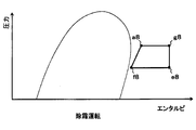
- the refrigerant circuit is switched to a refrigerant circuit through which the refrigerant flows as shown by the black arrows in FIG. That is, a refrigeration cycle in which the refrigerant circulates in the order of the compressor 11 ⁇ the heat storage member 17 ⁇ (the bypass passage 13 a ⁇ ) the expansion valve 15 ⁇ the outdoor heat exchanger 16 ⁇ the compressor 11 is configured. And in the refrigeration cycle apparatus 10a at the time of a defrost operation, as shown to the Mollier diagram of FIG. 8, the state of a refrigerant
- the heat storage member 17 is used. Until the temperature becomes equal to that of the refrigerant, the heat stored in the heat storage member 17 is absorbed (a8 point ⁇ g8 point in FIG. 8). At this time, the heat storage member 17 radiates the stored heat by the phase transition of the strongly correlated electron material from the metal to the insulator.
- the refrigerant that has absorbed heat from the heat storage member 17 flows into the expansion valve 15 via the bypass passage 13a and is depressurized (point g8 ⁇ point e8 in FIG. 8).
- the refrigerant decompressed by the expansion valve 15 flows into the outdoor heat exchanger 16.
- the refrigerant flowing into the outdoor heat exchanger 16 dissipates heat to the outdoor heat exchanger 16 and melts frost (point e8 ⁇ point f8 in FIG. 8). As a result, the outdoor heat exchanger 16 is defrosted.
- the refrigerant that has flowed out of the outdoor heat exchanger 16 is sucked into the compressor 11 and the pressure is increased again (point f8 ⁇ point a8 in FIG. 8).
- the outdoor heat exchanger 16 can be defrosted by heating the outdoor heat exchanger 16 using the heat stored in the heat storage member 17 as a heat source.
- the outdoor heat exchanger 16 can be heated using the heat stored in the heat storage member 17 as a heat source, as in the first embodiment. As a result, the outdoor heat exchanger 16 can be defrosted while suppressing an increase in energy consumption of the compressor 11.
- the refrigeration cycle apparatus 10b fulfills the function of cooling or heating the blown air that is blown into the vehicle interior that is the air-conditioning target space in the vehicle air conditioner. Accordingly, the blown air becomes a fluid to be heated by the refrigeration cycle apparatus 10b.
- a cooling operation for cooling the blown air, a dehumidifying heating operation for reheating the blown air that has been cooled and dehumidified, and a heating operation for heating the blown air (normal in the first embodiment) Corresponding to operation) and defrosting operation for defrosting the outdoor heat exchanger 16 can be switched. Therefore, in FIG. 9, the refrigerant flow during the cooling operation is indicated by hatched arrows, the refrigerant flow during the dehumidifying heating operation is indicated by hatched arrows, and the refrigerant flow during the heating operation is indicated by white arrows. The refrigerant flow during the frost operation is indicated by black arrows.
- an indoor evaporator 21, a cooling expansion valve 22, a heating bypass passage 23a, a heating on-off valve 23, and an accumulator 24 are added to the refrigeration cycle apparatus 10 described in the first embodiment.
- the bypass passage 13a and the on-off valve 13 are eliminated.
- the indoor evaporator 21 is disposed in a refrigerant flow path that connects the four-way valve 14 and the suction port side of the compressor 11.
- the indoor evaporator 21 evaporates the low-pressure refrigerant decompressed by the cooling expansion valve 22 by heat exchange with the blown air blown from the blower 12a during the dehumidifying heating operation and the cooling operation, thereby A cooling heat exchanger for cooling.
- the basic configuration of the cooling expansion valve 22 is the same as that of the expansion valve 15 described in the first embodiment. Further, the cooling expansion valve 22 has a fully closed function of closing the refrigerant passage from the four-way valve 14 to the refrigerant inlet of the indoor evaporator 21 with the throttle passage fully closed. Therefore, the cooling expansion valve 22 and the four-way valve 14 constitute a refrigerant circuit switching device that switches the refrigerant circuit.
- the cooling expansion valve 22 is in a throttle state that exerts a refrigerant decompression action during the dehumidifying heating operation and the cooling operation. Further, during the heating operation and the defrosting operation, the refrigerant passage is fully closed.
- the refrigeration cycle apparatus 10b is provided with a bypass passage 23a for heating that causes the refrigerant flowing out of the four-way valve 14 to bypass the cooling expansion valve 22 and the indoor evaporator 21 and lead to the refrigerant outlet side of the indoor evaporator 21. It has been.
- a heating on / off valve 23 that opens and closes the heating bypass passage 23a is disposed in the heating bypass passage 23a.
- the basic configuration of the heating on-off valve 23 is the same as that of the on-off valve 13 described in the first embodiment.
- the heating on-off valve 23 forms a refrigerant circuit switching device together with the four-way valve 14 and the cooling expansion valve 22. More specifically, the heating on-off valve 23 closes the heating bypass passage 23a during the dehumidifying heating operation and the cooling operation, and opens the heating bypass passage 23a during the heating operation and the defrosting operation.
- the accumulator 24 separates the gas / liquid of the refrigerant that has flowed out of the indoor evaporator 21 or the refrigerant that has flowed out of the bypass passage 23a for heating, stores excess liquid-phase refrigerant in the cycle, and separates the vapor-phase refrigerant that has been separated. Is a gas-liquid separator that flows out to the suction side of the compressor 11.
- blower 12a the indoor evaporator 21, and the indoor radiator 12 of the present embodiment are disposed in the air conditioning casing 30.
- the air conditioning casing 30 forms an air passage through which blown air flows.
- the blower 12a is disposed on the most upstream side of the air flow in the air passage.
- the indoor evaporator 21 and the indoor radiator 12 are arranged in this order on the downstream side of the air passage blower 12a. Therefore, in the air conditioning casing 30, the blown air that has passed through the indoor evaporator 21 can further flow into the indoor radiator 12.
- An air mix door 31 is disposed downstream of the indoor evaporator 21 in the air passage and upstream of the indoor radiator 12.
- the air mix door 31 adjusts the air volume ratio between the blown air that has passed through the indoor evaporator 21 and the blown air that flows into the indoor radiator 12 and the blown air that bypasses the indoor radiator 12 and flows downstream. It is a ratio adjustment device.
- the air mix door 31 is connected to an electric actuator (servo motor) that drives and displaces the air mix door 31.
- the operation of the electric actuator is controlled by a control signal output from the control device 40.
- Other configurations are the same as those of the first embodiment.
- the cooling operation, the dehumidifying heating operation, the heating operation, and the defrosting operation can be switched. Switching between these operations is performed by executing an air conditioning control program stored in advance in the control device 40.
- the air conditioning control program is executed when the operation switch of the operation panel 41 is turned on.
- the detection signals of the air conditioning control sensor group and the operation signals from various operation switches are read. And based on the value of the read detection signal and operation signal, the target blowing temperature TAO which is the target temperature of the blowing air which blows into the vehicle interior is calculated.
- the cooling operation is executed. Further, in the state where the cooling switch is turned on, when the target blowing temperature TAO is equal to or higher than the cooling reference temperature KT, the dehumidifying heating operation is executed. Further, when the cooling switch is not turned on, the heating operation is executed.
- the cooling operation is executed when the outside air temperature is relatively high mainly in summer. Also, dehumidifying and heating operation is performed mainly in early spring or early winter. Also, the heating operation is performed when the outside air temperature is relatively low, such as in winter. Further, during the heating operation, the defrosting operation is performed when it is determined by the frost determination unit that frost formation has occurred in the outdoor heat exchanger 16. Below, the operation
- Cooling operation First, the operation during the cooling operation will be described.
- the control device 40 fully opens the expansion valve 15, closes the cooling expansion valve 22, closes the heating on-off valve 23, and closes the refrigerant outlet side of the indoor radiator 12 and one of the outdoor heat exchanger 16.
- the operation of the four-way valve 14 is controlled so that one refrigerant inlet / outlet side of the expansion valve 15 and the inlet side of the compressor 11 are connected simultaneously with the refrigerant inlet / outlet side.
- the control device 40 controls the operation of the electric actuator of the air mix door 31 so that the blown air that has passed through the indoor evaporator 21 bypasses the indoor radiator 12. Further, the control device 40 responds to the detection signal of the air conditioning control sensor group so that the temperature of the blown air blown into the passenger compartment approaches the target blown temperature TAO, the compressor 11, the blower 12a, and the blower fan 16a. And the operation of the cooling expansion valve 22 is controlled.
- control device 40 of the present embodiment controls the operation of the compressor 11 so that the refrigerant evaporation temperature in the indoor evaporator 21 is 3 ° C. or higher during the cooling operation and the dehumidifying heating operation. Therefore, in the refrigeration cycle apparatus 10b of this embodiment, frost formation does not occur in the indoor evaporator 21, and defrosting of the indoor evaporator 21 is not necessary.
- the refrigerant circuit is switched to the refrigerant circuit through which the refrigerant flows as shown by the hatched arrows in FIG. That is, compressor 11 ⁇ (indoor radiator 12 ⁇ four-way valve 14 ⁇ ) outdoor heat exchanger 16 ⁇ (expansion valve 15 ⁇ ) heat storage member 17 ⁇ (four-way valve 14 ⁇ ) cooling expansion valve 22 ⁇ indoor evaporator 21 ⁇
- compressor 11 indoor radiator 12 ⁇ four-way valve 14 ⁇
- outdoor heat exchanger 16 ⁇ (expansion valve 15 ⁇ ) heat storage member 17 ⁇ (four-way valve 14 ⁇ ) cooling expansion valve 22 ⁇ indoor evaporator 21 ⁇
- the refrigerant circuit in which the refrigerant circulates in the order of accumulator 24 ⁇ compressor 11 is switched.
- the high-temperature and high-pressure refrigerant discharged from the compressor 11 flows into the outdoor heat exchanger 16 through the indoor radiator 12 and the four-way valve 14.
- the blown air that has been blown from the blower 12 a and passed through the indoor evaporator 21 flows around the indoor radiator 12 by the air mix door 31.
- coolant which passes the indoor heat radiator 12 does not thermally radiate to blowing air.
- the high-temperature and high-pressure refrigerant flowing into the outdoor heat exchanger 16 exchanges heat with the outside air blown from the blower fan 16a to radiate heat.
- the high-pressure refrigerant that has flowed out of the outdoor heat exchanger 16 flows into the cooling expansion valve 22 via the four-way valve 14 without being depressurized because the expansion valve 15 is fully open.
- the high-pressure refrigerant radiates heat to the heat storage member 17 until the temperature of the heat storage member 17 becomes equal to that of the high-pressure refrigerant when flowing through the refrigerant pipe from the expansion valve 15 to the four-way valve 14.
- the refrigerant that has flowed into the cooling expansion valve 22 in the throttle state is depressurized until it becomes a low-pressure refrigerant.
- the low-pressure refrigerant decompressed by the cooling expansion valve 22 flows into the indoor evaporator 21.
- the refrigerant flowing into the indoor evaporator 21 absorbs heat from the blown air blown from the blower 12a and evaporates. Thereby, blowing air is cooled.
- the low-pressure refrigerant that has flowed out of the indoor evaporator 21 flows into the accumulator 24 and is separated into gas and liquid.
- the gas-phase refrigerant separated by the accumulator 24 is sucked into the compressor 11 and compressed again.
- the vehicle interior can be cooled by cooling the blown air with the indoor evaporator 21 and blowing the cooled blown air into the vehicle interior.
- the control device 40 causes the expansion valve 15 and the cooling expansion valve 22 to be in a throttle state, closes the heating on-off valve 23, and closes the refrigerant outlet side of the indoor radiator 12 and one inlet / outlet side of the expansion valve 15. And the operation of the four-way valve 14 is controlled so that one refrigerant inlet / outlet side of the outdoor heat exchanger 16 and the inlet side of the compressor 11 are connected.
- the control device 40 controls the operation of the electric actuator of the air mix door 31 so that the blown air that has passed through the indoor evaporator 21 passes through the indoor radiator 12. Further, the control device 40 responds to the detection signal of the air conditioning control sensor group so that the temperature of the blown air blown into the passenger compartment approaches the target blown temperature TAO, the compressor 11, the blower 12a, and the blower fan 16a. The operation of the expansion valve 15 and the cooling expansion valve 22 is controlled.
- the refrigerant circuit is switched to the refrigerant circuit through which the refrigerant flows as shown by the hatched arrows in FIG. That is, compressor 11 ⁇ indoor radiator 12 ⁇ (four-way valve 14 ⁇ ) heat storage member 17 ⁇ expansion valve 15 ⁇ outdoor heat exchanger 16 ⁇ (four-way valve 14 ⁇ ) cooling expansion valve 22 ⁇ indoor evaporator 21 ⁇ accumulator 24 ⁇
- the refrigerant circuit is switched to the refrigerant circuit in the order of the compressor 11.
- the high-temperature and high-pressure refrigerant discharged from the compressor 11 flows into the indoor radiator 12.
- the air mix door 31 is displaced so that the blown air (cold air) that has passed through the indoor evaporator 21 passes through the indoor radiator 12
- the refrigerant that passes through the indoor radiator 12 Heat is radiated to the blown air after passing through the evaporator 21.
- the blast air after passing through the indoor evaporator 21 is heated.
- the high-pressure refrigerant that has flowed out of the indoor radiator 12 flows into the expansion valve 15 via the four-way valve 14.
- the high-pressure refrigerant radiates heat to the heat storage member 17 until the temperature of the heat storage member 17 becomes equal to that of the high-pressure refrigerant when flowing through the refrigerant pipe from the four-way valve 14 to the expansion valve 15.
- the refrigerant decompressed by the expansion valve 15 flows into the outdoor heat exchanger 16. At this time, when the temperature of the refrigerant decompressed by the expansion valve 15 is higher than the outside air temperature, the refrigerant flowing into the outdoor heat exchanger 16 radiates heat to the outside air blown from the blower fan 16a. On the other hand, when the temperature of the refrigerant decompressed by the expansion valve 15 is lower than the outside air temperature, the refrigerant flowing into the outdoor heat exchanger 16 absorbs heat from the outside air blown from the blower fan 16a.
- the throttle opening of the expansion valve 15 is reduced and the throttle opening of the cooling expansion valve 22 is reduced as the heating capacity required for heating the blown air is increased.
- the outdoor heat exchanger 16 is caused to function as a heat exchanger for radiating the refrigerant, and when the heating capacity is relatively large, the outdoor heat exchanger 16 16 functions as a heat exchanger for evaporating the refrigerant.
- the refrigerant that has flowed out of the outdoor heat exchanger 16 flows into the cooling expansion valve 22 through the four-way valve 14.
- the refrigerant flowing into the cooling expansion valve 22 is depressurized until it becomes a low-pressure refrigerant.
- the low-pressure refrigerant decompressed by the cooling expansion valve 22 flows into the indoor evaporator 21.
- the refrigerant flowing into the indoor evaporator 21 absorbs heat from the blown air blown from the blower 12a and evaporates. Thereby, blowing air is cooled. Subsequent operations are the same as in the cooling operation.
- the blower air is cooled and dehumidified by the indoor evaporator 21, and the dehumidified blown air is reheated by the indoor radiator 12.
- the dehumidification heating in a vehicle interior can be performed by blowing off the reheated ventilation air to a vehicle interior.
- the control device 40 sets the expansion valve 15 in the throttle state, fully closes the cooling expansion valve 22, opens the heating on-off valve 23, and opens one of the expansion valve 15 and the refrigerant outlet side of the indoor radiator 12.
- the operation of the four-way valve 14 is controlled so that one refrigerant inflow / outlet side of the outdoor heat exchanger 16 and the suction port side of the compressor 11 are connected simultaneously with connection to the inflow / outlet side.
- the control device 40 controls the operation of the electric actuator of the air mix door 31 so that the blown air that has passed through the indoor evaporator 21 passes through the indoor radiator 12. Further, the control device 40 responds to the detection signal of the air conditioning control sensor group so that the temperature of the blown air blown into the passenger compartment approaches the target blown temperature TAO, the compressor 11, the blower 12a, and the blower fan 16a. And the operation of the expansion valve 15 is controlled.
- the refrigerant circuit is switched to the refrigerant circuit through which the refrigerant flows as shown by the white arrow in FIG. That is, compressor 11 ⁇ indoor radiator 12 ⁇ (four-way valve 14 ⁇ ) heat storage member 17 ⁇ expansion valve 15 ⁇ outdoor heat exchanger 16 ⁇ (four-way valve 14 ⁇ bypass path for heating 23 a ⁇ ) accumulator 24 ⁇ compressor 11 It switches to the refrigerant circuit in which a refrigerant circulates in order.
- a refrigeration cycle substantially equivalent to that during normal operation of the refrigeration cycle apparatus 10 described in the first embodiment is configured.
- indoor air can be heated by heating the blown air with the indoor radiator 12 and blowing the heated blown air into the room.
- the heat storage member 17 can store heat.
- the control device 40 sets the expansion valve 15 in the throttle state, fully closes the cooling expansion valve 22, opens the heating on-off valve 23, opens the refrigerant outlet side of the indoor radiator 12, and the outdoor heat exchanger 16.
- the operation of the four-way valve 14 is controlled so that one refrigerant inlet / outlet side of the expansion valve 15 and one inlet side of the compressor 11 are connected simultaneously.
- the control device 40 controls the operation of the electric actuator of the air mix door 31 so that the blown air that has passed through the indoor evaporator 21 bypasses the indoor radiator 12. Further, the control device 40 lowers the refrigerant discharge capacity of the compressor 11 than during the heating operation, stops the operation of the blower 12a, and increases the throttle opening of the expansion valve 15 than during the heating operation.
- the refrigerant circuit is switched to the refrigerant circuit through which the refrigerant flows as shown by the black arrows in FIG. That is, compressor 11 ⁇ (indoor radiator 12 ⁇ four-way valve 14 ⁇ ) outdoor heat exchanger 16 ⁇ expansion valve 15 ⁇ heat storage member 17 ⁇ (four-way valve 14 ⁇ heating bypass passage 23a ⁇ ) accumulator 24 ⁇ compressor 11 It switches to the refrigerant circuit in which a refrigerant circulates in order.
- the air blower 12a is stopped, and the air mix door 31 is displaced so that the blown air (cold air) that has passed through the indoor evaporator 21 bypasses the indoor radiator 12.
- the refrigerant passing through the vessel 12 does not radiate heat to the blown air. Therefore, during the defrosting operation, a refrigeration cycle substantially equivalent to that during the defrosting operation of the refrigeration cycle apparatus 10 described in the first embodiment is configured.
- the frost attached to the outdoor heat exchanger 16 can be melted and removed as in the first embodiment. That is, according to the refrigeration cycle apparatus 10b of the present embodiment, the outdoor heat exchanger 16 can be defrosted while suppressing an increase in energy consumption of the compressor 11 as in the first embodiment.
- the refrigeration cycle apparatus 10c of the present embodiment also performs cooling operation for cooling the blown air by switching the refrigerant circuit, dehumidifying heating operation for reheating the blown air that has been cooled and dehumidified, The heating operation for heating the blown air and the defrosting operation for defrosting the outdoor heat exchanger 16 can be switched.
- the refrigeration cycle apparatus 10c is similar to the refrigeration cycle apparatus 10a described in the third embodiment in the same manner as in the fourth embodiment, except that the indoor evaporator 21, the cooling expansion valve 22, the heating bypass passage 23a, and the heating on-off valve 23, the accumulator 24 is added, and the bypass passage 13a and the on-off valve 13 are abolished.
- Other configurations are the same as those of the third embodiment.
- the operation of the refrigeration cycle apparatus 10c of the present embodiment having the above configuration will be described.
- the cooling operation, the dehumidifying heating operation, the heating operation, and the defrosting operation are switched as in the refrigeration cycle apparatus 10b described in the fourth embodiment.
- operation is demonstrated.
- Cooling operation First, the operation during the cooling operation will be described. During the cooling operation, the control device 40 opens the expansion valve 15 fully, sets the cooling expansion valve 22 in the throttle state, and closes the heating on-off valve 23.
- the control device 40 controls the operation of the electric actuator of the air mix door 31 so that the blown air that has passed through the indoor evaporator 21 bypasses the indoor radiator 12. Further, the control device 40 responds to the detection signal of the air conditioning control sensor group so that the temperature of the blown air blown into the passenger compartment approaches the target blown temperature TAO, the compressor 11, the blower 12a, and the blower fan 16a. And the operation of the cooling expansion valve 22 is controlled.
- the refrigerant circuit is switched to the refrigerant circuit through which the refrigerant flows as shown by the hatched arrows in FIG. That is, the refrigerant circulates in the order of the compressor 11 ⁇ the heat storage member 17 ⁇ (the indoor radiator 12 ⁇ the expansion valve 15 ⁇ ) the outdoor heat exchanger 16 ⁇ the cooling expansion valve 22 ⁇ the indoor evaporator 21 ⁇ the accumulator 24 ⁇ the compressor 11. Switch to refrigerant circuit.
- a refrigeration cycle substantially equivalent to that during the cooling operation of the refrigeration cycle apparatus 10b described in the fourth embodiment is configured.
- the vehicle interior can be cooled by cooling the blown air by the indoor evaporator 21 and blowing the cooled blown air into the vehicle interior, as in the fourth embodiment.
- the control device 40 controls the operation of the electric actuator of the air mix door 31 so that the blown air that has passed through the indoor evaporator 21 passes through the indoor radiator 12. Furthermore, the control device 40 further controls the compressor 11 so that the temperature of the blown air blown into the vehicle interior approaches the target blowing temperature TAO according to the detection signal of the sensor group for air conditioning control. The operation of the blower 12a, the blower fan 16a, the expansion valve 15 and the cooling expansion valve 22 is controlled.
- the refrigerant circuit is switched to the refrigerant circuit through which the refrigerant flows as shown by the hatched arrows in FIG. That is, the refrigerant circuit in which the refrigerant circulates in the order of the compressor 11 ⁇ the heat storage member 17 ⁇ the indoor radiator 12 ⁇ the expansion valve 15 ⁇ the outdoor heat exchanger 16 ⁇ the cooling expansion valve 22 ⁇ the indoor evaporator 21 ⁇ the accumulator 24 ⁇ the compressor 11. Can be switched to.
- a refrigeration cycle substantially equivalent to that during the dehumidifying heating operation of the refrigeration cycle apparatus 10b described in the fourth embodiment is configured.
- the blower air is cooled and dehumidified by the indoor evaporator 21 as in the fourth embodiment, and the dehumidified blown air is reheated by the indoor radiator 12.
- the dehumidification heating in a vehicle interior can be performed by blowing off the reheated ventilation air to a vehicle interior.
- the control device 40 controls the operation of the electric actuator of the air mix door 31 so that the blown air that has passed through the indoor evaporator 21 passes through the indoor radiator 12. Further, the control device 40 responds to the detection signal of the air conditioning control sensor group so that the temperature of the blown air blown into the passenger compartment approaches the target blown temperature TAO, the compressor 11, the blower 12a, and the blower fan 16a. And the operation of the expansion valve 15 is controlled.
- the refrigerant circuit is switched to the refrigerant circuit through which the refrigerant flows as shown by the white arrow in FIG. That is, it is switched to a refrigerant circuit in which refrigerant circulates in the order of the compressor 11 ⁇ the heat storage member 17 ⁇ the indoor radiator 12 ⁇ the expansion valve 15 ⁇ the outdoor heat exchanger 16 ⁇ (heating bypass passage 23 a ⁇ ) accumulator 24 ⁇ compressor 11. .
- a refrigeration cycle substantially equivalent to that during normal operation of the refrigeration cycle apparatus 10a described in the third embodiment is configured.
- indoor air can be heated by heating the blown air by the indoor radiator 12 and blowing the heated blown air into the room.
- the heat storage member 17 can store heat.
- the control device 40 controls the operation of the electric actuator of the air mix door 31 so that the blown air that has passed through the indoor evaporator 21 bypasses the indoor radiator 12. Further, the control device 40 lowers the refrigerant discharge capacity of the compressor 11 than during the heating operation, stops the operation of the blower 12a, and increases the throttle opening of the expansion valve 15 than during the heating operation.
- the refrigerant circuit is switched to the refrigerant circuit through which the refrigerant flows as shown by the black arrows in FIG. That is, in the refrigerant circuit in which the refrigerant circulates in the order of the compressor 11 ⁇ the heat storage member 17 ⁇ (the indoor radiator 12 ⁇ ) the expansion valve 15 ⁇ the outdoor heat exchanger 16 ⁇ (the bypass passage 23 a for heating) ⁇ the accumulator 24 ⁇ the compressor 11. Can be switched.
- the air blower 12a is stopped, and the air mix door 31 is displaced so that the blown air (cold air) that has passed through the indoor evaporator 21 passes through the indoor radiator 12.
- the refrigerant passing through the vessel 12 does not radiate heat to the blown air. Accordingly, during the defrosting operation, a refrigeration cycle substantially equivalent to that during the defrosting operation of the refrigeration cycle apparatus 10a described in the third embodiment is configured.
- the frost attached to the outdoor heat exchanger 16 can be melted and removed as in the third embodiment. That is, according to the refrigeration cycle apparatus 10c of the present embodiment, the outdoor heat exchanger 16 can be defrosted while suppressing an increase in energy consumption of the compressor 11 as in the third embodiment.
- the additive that can be used for adjusting the transition temperature is not limited to W.
- Cr chromium
- Nb niobium
- Ti titanium
- Al aluminum
- Mn manganese
- Fe iron
- Co cobalt
- Ni nickel
- Cu copper
- Y yttrium
- Zr zirconium
- Mo molecular weight
- Ru ruthenium
- Rh Rhodium
- Pd palladium
- Hf hafnium
- Ta tantalum
- Re (rhenium) Can be adopted.
- the indoor radiator 12 includes a tank that collects or distributes refrigerant, a plurality of tubes that distribute the refrigerant, and a tank that collects or distributes refrigerant by connecting a plurality of tubes.
- Adopt a mold heat exchanger. And you may fix the heat storage member 17a for heating formed in the thin plate shape to a tube by adhesion
- the heating target fluid (blast air) is used in the heating heat storage member 17a. ) Can be heated.
- the compressor 11 is not limited to this.
- the compressor 11 an engine-driven variable displacement compressor or a fixed displacement compressor may be employed.
- the indoor radiator 12 a so-called subcool type condenser having a condensing part for condensing the high-temperature and high-pressure refrigerant and a supercooling part for supercooling the refrigerant condensed in the condensing part may be adopted.
- the refrigerant of the refrigeration cycle apparatuses 10, 10a to 10c is not mentioned.
- any refrigerant that can be used in a general refrigeration cycle will affect the heat storage performance of the heat storage members 17, 17a. I know I will not give it. Accordingly, R1234yf, R134a, R600a, R410A, R404A, R32, R407C, HFO-1234ze, HFO-1234zd, and the like can be used as the refrigerant.
- the refrigeration cycle apparatuses 10, 10a to 10c according to the present disclosure are applied to an air conditioner has been described, but application of the refrigeration cycle apparatuses 10, 10a to 10c is not limited thereto. That is, the refrigeration cycle apparatus according to the present disclosure can be applied to an apparatus that is in a usage mode in which frost formation can occur in the evaporator (outdoor heat exchanger 16).
- the present invention may be applied to a hot water supply apparatus that heats hot water that is a fluid to be heated with a radiator using heat absorbed from outside air by an evaporator as a heat source.
- the means disclosed in the above embodiments may be appropriately combined within a practicable range.
- the heating heat storage member 17a described in the second embodiment may be applied to the refrigeration cycle apparatuses 10a to 10c described in the third to fifth embodiments.
Landscapes
- Engineering & Computer Science (AREA)
- Physics & Mathematics (AREA)
- Thermal Sciences (AREA)
- Mechanical Engineering (AREA)
- General Engineering & Computer Science (AREA)
- Chemical & Material Sciences (AREA)
- Chemical Kinetics & Catalysis (AREA)
- General Chemical & Material Sciences (AREA)
- Fluid Mechanics (AREA)
- Combustion & Propulsion (AREA)
- Materials Engineering (AREA)
- Organic Chemistry (AREA)
- Air Conditioning Control Device (AREA)
- Defrosting Systems (AREA)
Abstract
通常運転時に室内放熱器(12)から流出した高圧冷媒の有する熱を蓄熱部材(17)に蓄熱させる冷媒回路に切り替え、蒸発器として機能する室外熱交換器(16)に着霜が生じた際には、蓄熱部材(17)に蓄熱された熱を熱源として室外熱交換器(16)を加熱して除霜する冷媒回路に切り替える。蓄熱部材(17)として、金属絶縁体転移する性質を有する遷移金属酸化物であるVO2(二酸化バナジウム)に添加物としてW(タングステン)を加えたものを採用し、冷媒の温度帯に応じた効率的な蓄熱あるいは放熱を行わせることによって、圧縮機の消費エネルギの増加を抑制する。
Description
本出願は、当該開示内容が参照によって本出願に組み込まれた、2016年4月28日に出願された日本特許出願2016-090708号を基にしている。
本開示は、蒸発器に着霜が生じた際に、これを除霜する除霜運転を行う冷凍サイクル装置に関する。
従来、特許文献1に、冷媒を蒸発させる蒸発器に着霜が生じた際に、これを除霜する除霜運転を行う冷凍サイクル装置が開示されている。この特許文献1の冷凍サイクル装置では、蒸発器に着霜が生じた際に、圧縮機から吐出された高温冷媒(すなわち、ホットガス)を蒸発器へ流入させることによって、蒸発器の除霜を行っている。
しかし、本開示の発明者らの検討によると、特許文献1の冷凍サイクル装置のように、ホットガスによって蒸発器の除霜を行うためには、除霜運転時であってもホットガスを吐出できるように圧縮機を作動させなければならない。このため、除霜運転を実行することは、圧縮機の消費エネルギを増加させてしまう原因となる。
さらに、放熱器にて圧縮機から吐出された高温冷媒と加熱対象流体(例えば、空調対象空間へ送風される送風空気)とを熱交換させて、加熱対象流体を加熱する冷凍サイクル装置では、除霜運転時には加熱対象流体の加熱能力が低下してしまう。
本開示は、上記点に鑑み、除霜運転を行う可能な冷凍サイクル装置において、圧縮機の消費エネルギの増加を抑制することを目的とする。
本開示の一つの態様による冷凍サイクル装置は、冷媒を圧縮して吐出する圧縮機と、冷媒を放熱させる放熱器と、冷媒を減圧させる減圧装置と、冷媒を蒸発させる蒸発器と、を備える。通常運転時には、圧縮機から吐出された高圧冷媒を放熱器にて放熱させ、放熱器から流出した冷媒を減圧装置にて減圧し、減圧装置にて減圧された低圧冷媒を蒸発器にて蒸発させ、さらに、蒸発器から流出した冷媒を前記圧縮機へ吸入させる。さらに、冷凍サイクル装置は、通常運転時に圧縮機の吐出側から減圧装置の入口側へ至る冷媒流路を流通する高圧冷媒の有する熱を蓄える固体の蓄熱部材を備え、蓄熱部材は、金属と絶縁体とに相変化することによって蓄熱あるいは放熱を行う強相関電子系材料を有し、蒸発器に生じた霜を取り除く除霜運転時には、蓄熱部材に蓄熱された熱を熱源として蒸発器を加熱する。
これによれば、除霜運転時に、蓄熱部材に蓄熱された熱を熱源として蒸発器を加熱するので、圧縮機の消費エネルギの増加を抑制しつつ、蒸発器の除霜を行うことができる。
さらに、蓄熱部材として、強相関電子系材料を有する固体のものを採用しているので、固体の状態のままで除霜に必要な熱の蓄熱あるいは放熱を行うことができる。従って、液体と固体との相変化、または、気体と固体との相変化によって蓄熱あるいは放熱を行う蓄熱剤を採用する場合に比べて、極めて容易に、冷凍サイクル装置に蓄熱部材を配置することができる。
また、強相関電子系材料として、遷移金属酸化物に添加物を加えたものを採用することで、転移温度(金属と絶縁体との相転移温度)を調整することが可能となる。従って、適用される冷凍サイクル装置の冷媒の温度帯に応じて、予め転移温度を適切に調整しておくことができる。これにより、蓄熱部材の効率的な蓄熱あるいは放熱を実現することができる。
(第1実施形態)
図1~図4を用いて、本開示の第1実施形態を説明する。本実施形態では、図1の全体構成図に示す冷凍サイクル装置10を、暖房装置に適用している。冷凍サイクル装置10は、暖房装置において、空調対象空間である室内へ送風される送風空気を加熱する機能を果たす。従って、冷凍サイクル装置10の加熱対象流体は、送風空気である。
図1~図4を用いて、本開示の第1実施形態を説明する。本実施形態では、図1の全体構成図に示す冷凍サイクル装置10を、暖房装置に適用している。冷凍サイクル装置10は、暖房装置において、空調対象空間である室内へ送風される送風空気を加熱する機能を果たす。従って、冷凍サイクル装置10の加熱対象流体は、送風空気である。
冷凍サイクル装置10では、冷媒回路を切り替えることによって、送風空気を加熱する通常運転(暖房運転)と、蒸発器としての機能を果たす室外熱交換器16に着霜が生じた際に、これを除霜するための除霜運転とを切り替えることができる。そこで、図1では、通常運転時の冷媒流れを白抜き矢印で示し、除霜運転時の冷媒流れを黒塗り矢印で示している。
冷凍サイクル装置10は、圧縮機11、室内放熱器12、四方弁14、膨張弁15、室外熱交換器16等を備えている。
圧縮機11は、冷凍サイクル装置10において、冷媒を吸入し、圧縮して吐出するものである。圧縮機11は、ハウジング内に固定容量型の圧縮機構、および圧縮機構を駆動する電動モータを収容して構成された電動圧縮機である。電動モータは、後述する制御装置40から出力される制御信号によって、その作動(回転数)が制御される。
圧縮機11の吐出口には、室内放熱器12の入口側が接続されている。室内放熱器12は、通常運転時に、圧縮機11から吐出された冷媒と送風機12aから送風された送風空気とを熱交換させて、送風空気を加熱する放熱器である。送風機12aは、制御装置40から出力される制御電圧によって回転数(送風空気量)が制御される電動式送風機である。
さらに、冷凍サイクル装置10には、圧縮機11から吐出された冷媒を、室内放熱器12を迂回させて、室内放熱器12の冷媒出口側へ導く迂回通路13aが設けられている。迂回通路13aには、迂回通路13aを開閉する開閉弁13が配置されている。
開閉弁13は、制御装置40から出力される制御信号によって、その作動が制御される電磁弁である。開閉弁13は、冷凍サイクル装置10の冷媒回路を切り替える冷媒回路切替装置を構成している。より具体的には、開閉弁13は、通常運転時には、迂回通路13aを閉じ、除霜運転時には、迂回通路13aを開く。
ここで、冷媒が迂回通路13aを通過する際に生じる圧力損失は、冷媒が室内放熱器12を通過する際に生じる圧力損失に対して極めて小さい。このため、開閉弁13が迂回通路13aを開いた際には、圧縮機11から吐出された冷媒のほぼ全流量が迂回通路13aを流通して室内放熱器12の冷媒出口側へ導かれる。
室内放熱器12の冷媒出口には、四方弁14の1つの冷媒入口側が接続されている。四方弁14は、制御装置40から出力される制御電圧によって、その作動が制御される電気式四方弁である。四方弁14は、開閉弁13とともに、冷媒回路を切り替える冷媒回路切替装置を構成している。
より具体的には、四方弁14は、通常運転時には、室内放熱器12の冷媒出口側と膨張弁15の一方の流入出口(すなわち、通常運転時における冷媒入口)側とを接続すると同時に室外熱交換器16の一方の冷媒流入出口(すなわち、通常運転時における冷媒出口)側と圧縮機11の吸入口側とを接続する冷媒回路に切り替える。また、除霜運転時には、室内放熱器12の冷媒出口側と室外熱交換器16の一方の冷媒流入出口側とを接続すると同時に膨張弁15の一方の流入出口側と圧縮機11の吸入口側とを接続する冷媒回路に切り替える。
膨張弁15は、絞り開度を変更可能に構成された弁体と、この弁体を変位させて絞り開度を変化させるステッピングモータからなる電動アクチュエータとを有する可変絞り機構で構成された減圧装置である。膨張弁15は、制御装置40から出力される制御信号(制御パルス)によって、その作動が制御される。
膨張弁15の他方の流入出口(すなわち、通常運転時における冷媒出口)には、室外熱交換器16の他方の冷媒流入出口側が接続されている。室外熱交換器16は、通常運転時に、内部を流通する冷媒を、送風ファン16aから送風された室外空気(外気)と熱交換させて蒸発させる蒸発器である。送風ファン16aは、制御装置40から出力される制御電圧によって回転数(送風空気量)が制御される電動式送風機である。
さらに、本実施形態の冷凍サイクル装置10では、四方弁14と膨張弁15とを接続する冷媒回路に蓄熱部材17を配置している。
本実施形態では、蓄熱部材17として、強相関電子系材料を有するものを採用している。ここで、強相関電子系材料とは、物質の中でも電子間に働く有効クーロン相互作用が強い物質である。
また、強相関電子系材料には、遷移金属酸化物、有機π電子系錯体等がある。本実施形態では、強相関電子系材料が持つ性質の一つである金属絶縁体転移の性質を利用するため、強相関電子系材料として、遷移金属酸化物であるVO2(二酸化バナジウム)、またはVO2に添加物を加えたものを採用している。遷移金属酸化物は、外部から熱エネルギを与えられると絶縁体から金属へ変化する性質を有する。
より詳細には、遷移金属酸化物では、遷移金属原子の最外殻電子間の有効クーロン相互作用が強いため、金属絶縁体転移温度より低い温度になっていると、最外殻電子が自由に動けない状態(絶縁体)となる。そして、絶縁体となっている遷移金属酸化物が、外部から金属絶縁体転移温度度以上となるまで熱エネルギを与えられると、最外殻電子が自由に動ける状態(金属)となる。
この絶縁体から金属への相転移の際に、熱エネルギが遷移金属酸化物に蓄えられる。すなわち、遷移金属酸化物が蓄熱する。この際に蓄熱される熱は、例えば、水分子が互いに自由に動けない状態になっている氷(固体)が、水分子が互いに自由に動ける水(液体)に相変化する際に、蓄えられる融解潜熱に相当する熱である。一方、遷移金属酸化物が金属から絶縁体へ相転移する際には、蓄えられていた熱が放熱される。
すなわち、この際に蓄熱される熱は、例えば、水分子が互いに自由に動けない状態になっている氷(固体)が、水分子が互いに自由に動ける水(液体)に相変化する際に、蓄えられる融解潜熱に相当する熱である。一方、遷移金属酸化物が金属から絶縁体へ相転移する際には、蓄えられていた熱が放熱される。従って、遷移金属酸化物は、金属と絶縁体とに相変化することによって、蓄熱あるいは放熱を行うことができる。
さらに、この相変化は、固体のままで行われる。そこで、本実施形態では、図2に示すように、遷移金属酸化物を円柱状に形成し、軸方向に複数の貫通穴を形成したものを蓄熱部材17としている。この蓄熱部材17は、四方弁14と膨張弁15とを接続する冷媒配管中に、専用の容器等に収容されることなく、冷媒と直接接触して熱移動が可能となるように配置されている。従って、蓄熱部材17は、通常運転時に圧縮機11の吐出口側から膨張弁15の入口側へ至る範囲の冷媒が流通する冷媒流路中に配置されている。
また、遷移金属酸化物は、添加物を加えることによって、転移温度(金属と絶縁体との相転移温度)を調整することができる。例えば、VO2の転移温度は、68℃であるが、本実施形態では、VO2にW(タングステン)を添加することによって、転移温度を20℃~40℃程度に調整したものを採用している。
次に、本実施形態の電気制御部について説明する。制御装置40は、CPU、ROMおよびRAM等を含む周知のマイクロコンピュータとその周辺回路から構成されている。制御装置40は、そのROM内に記憶された制御プログラムに基づいて各種演算、処理を行う。そして、出力側に接続された各種電気式のアクチュエータ(11、12a、13、14、15、16a)の作動を制御する。
制御装置40の入力側には、内気温センサ、外気温センサ、室外器温度センサ等の空調制御用のセンサ群が接続され、これらのセンサ群の検出値が入力される。内気温センサは、空調対象空間である室内の温度を検出する内気温検出装置である。外気温センサは、外気温を検出する外気温検出装置である。室外器温度センサは、室外熱交換器16の温度(室外熱交換器16における冷媒蒸発温度)を検出する蒸発器温度検出装置である。
さらに、制御装置40の入力側には、操作パネル41が接続され、操作パネル41に設けられた各種操作スイッチからの操作信号が制御装置40へ入力される。各種操作スイッチとしては、空調(本実施形態では、暖房)を行うことを要求する作動スイッチ、室内温度を設定する温度設定スイッチ等が設けられている。
なお、本実施形態の制御装置40は、その出力側に接続された各種の制御対象機器の作動を制御する制御部が一体的に構成されたものであるが、制御装置40のうち、各制御対象機器の作動を制御する構成(ハードウェアおよびソフトウェア)が各制御対象機器の制御部を構成している。
次に、上記構成における本実施形態の冷凍サイクル装置10の作動について説明する。本実施形態の冷凍サイクル装置10では、通常運転と除霜運転とを切り替えることができる。まず、通常運転時の作動について説明する。通常運転は、操作パネル41の作動スイッチが投入(ON)され、制御装置40の着霜判定部が室外熱交換器16に着霜が生じていないと判定した際に実行される。
ここで、このような着霜判定部としては、室外器温度センサの検出値Teが、外気温センサの検出値Tamから予め定めた基準温度αを減算した値よりも低くなっている際に(すなわち、Te<Tam-αになっている際に)、室外熱交換器16に着霜が生じていると判定する制御プログラム等を採用することができる。
通常運転時には、制御装置40が、開閉弁13を閉じ、室内放熱器12の冷媒出口側と膨張弁15の一方の流入出口側とを接続すると同時に室外熱交換器16の一方の冷媒流入出口側と圧縮機11の吸入口側とを接続するように四方弁14の作動を制御する。
また、制御装置40は、空調制御用のセンサ群の検出信号に応じて、内気温センサの検出値が温度設定スイッチにて設定された設定温度に近づくように、圧縮機11、送風機12a、膨張弁15、および送風ファン16aの作動を制御する。
これにより、通常運転時には、図1の白抜き矢印に示すように冷媒が流れる冷媒回路に切り替えられる。すなわち、圧縮機11→室内放熱器12→(四方弁14→)蓄熱部材17→膨張弁15→室外熱交換器16→(四方弁14→)圧縮機11の順に冷媒が循環する冷媒回路に切り替えられる。従って、通常運転時には、図3のモリエル線図に示すように、冷媒の状態が変化する。
より詳細には、圧縮機11から吐出された高温高圧冷媒(図3のa3点)は、開閉弁13が閉じているので、室内放熱器12へ流入する。室内放熱器12へ流入した冷媒は、送風機12aから送風された送風空気と熱交換して放熱する(図3のa3点→b3点)。これにより、送風空気が加熱される。
室内放熱器12から流出した高圧冷媒は、四方弁14から膨張弁15へ至る冷媒配管を流通する際に、蓄熱部材17の温度が高圧冷媒と同等となるまで、蓄熱部材17に放熱する(図3のb3点→d3点)。この際、蓄熱部材17では、遷移金属酸化物が絶縁体から金属へ相転移することによって、高圧冷媒が放熱した熱を蓄熱する。
膨張弁15へ流入した冷媒は、低圧冷媒となるまで減圧される(図3のd3点→e3点)。膨張弁15にて減圧された低圧冷媒は、室外熱交換器16へ流入する。室外熱交換器16へ流入した冷媒は、送風ファン16aから送風された外気から吸熱して蒸発する(図3のe3点→f3点)。
室外熱交換器16から流出した低圧冷媒は、四方弁14を介して、圧縮機11へ吸入され、再び圧縮される(図3のf3点→a3点)。以上の如く、通常運転時の冷凍サイクル装置10では、室内放熱器12にて送風空気を加熱し、加熱された送風空気を室内へ吹き出すことによって、室内の暖房を行うことができる。さらに、蓄熱部材17に蓄熱させることができる。
次に、除霜運転について説明する。除霜運転は、通常運転の実行中に、制御装置40の着霜判定部が室外熱交換器16に着霜が生じていると判定した際に、予め定めた除霜時間が経過するまで実行される。
除霜運転時には、制御装置40が、開閉弁13を開き、室内放熱器12の冷媒出口側と室外熱交換器16の一方の冷媒流入出口側とを接続すると同時に膨張弁15の一方の流入出口側と圧縮機11の吸入口側とを接続するように四方弁14の作動を制御する。また、制御装置40は、通常運転時よりも圧縮機11の冷媒吐出能力を低下させ、送風機12aの作動を停止し、通常運転時よりも膨張弁15の絞り開度を増加させる。
これにより、除霜運転時には、図1の黒塗り矢印に示すように冷媒が流れる冷媒回路に切り替えられる。すなわち、圧縮機11→(迂回通路13a→四方弁14→)蓄熱部材17→膨張弁15→室外熱交換器16→(四方弁14→)圧縮機11の順に冷媒が循環する冷媒回路に切り替えられる。従って、除霜運転時には、図4のモリエル線図に示すように、冷媒の状態が変化する。
なお、図4のモリエル線図では、通常運転で説明した図3のモリエル線図とサイクル構成上同等の箇所の冷媒の状態を、図3と同一の符号(アルファベット)で示し、添字(数字)のみ変更している。このことは、後述する実施形態で説明するモリエル線図においても同様である。
より詳細には、圧縮機11から吐出された冷媒(図4のa4点)は、開閉弁13が開いているので、迂回通路13aおよび四方弁14を介して、室外熱交換器16へ流入する。室外熱交換器16へ流入した冷媒は、室外熱交換器16に放熱して霜を融解する(図4のa4点→e4点)。これにより、室外熱交換器16の除霜がなされる。室外熱交換器16から流出した冷媒は、膨張弁15にて減圧される(図4のe4点→d4点)。
膨張弁15にて減圧された冷媒は、膨張弁15から四方弁14へ至る冷媒配管を流通する際に、蓄熱部材17の温度が膨張弁15にて減圧された冷媒と同等となるまで、蓄熱部材17に蓄えられた熱を吸熱する(図4のd4点→c4点)。この際、蓄熱部材17では、遷移金属酸化物が金属から絶縁体へ相転移することによって、蓄熱された熱を放熱する。
蓄熱部材17から吸熱した冷媒は、四方弁14を介して、圧縮機11へ吸入され、再び昇圧される(図4のc4点→a4点)。以上の如く、除霜運転時の冷凍サイクル装置10では、蓄熱部材17に蓄熱された熱を熱源として室外熱交換器16を加熱して、室外熱交換器16の除霜を行うことができる。
さらに、除霜運転では、圧縮機11の冷媒吐出能力を通常運転時よりも低下させ、蓄熱部材17に蓄えられた熱を熱源として室外熱交換器16を加熱するので、圧縮機11の消費エネルギの増加を抑制しつつ、室外熱交換器16の除霜を行うことができる。
これに加えて、本実施形態の冷凍サイクル装置10では、蓄熱部材17として、強相関電子系材料を有する固体のものを採用しているので、金属と絶縁体との相変化によって固体の状態のままで除霜に必要な熱の蓄熱あるいは放熱を行うことができる。従って、液体と固体との相変化、または、気体と固体との相変化によって蓄熱あるいは放熱を行う蓄熱剤を採用する場合に比べて、極めて容易に、冷凍サイクル装置10の冷媒配管内に蓄熱部材17を配置することができる。
そして、具体的に、蓄熱部材17を、通常運転時に圧縮機11の吐出口側から膨張弁15の入口側へ至る冷媒配管中に配置しているので、極めて容易に、高圧冷媒の有する熱を蓄熱部材17に蓄熱させることができる。
また、本実施形態の冷凍サイクル装置10では、強相関電子系材料として、遷移金属酸化物であるVO2にWを添加することによって、転移温度を20℃~40℃程度に調整したものを採用している。従って、膨張弁15から四方弁14へ至る冷媒配管を流通する冷媒の温度に応じて、強相関電子系材料を相転移させることができ、効率的な蓄熱あるいは放熱を実現することができる。
(第2実施形態)
本実施形態では、第1実施形態に対して、図5の全体構成図に示すように、加熱用蓄熱部材17aを追加した例を説明する。図5では、第1実施形態と同一もしくは均等部分には同一の符号を付している。このことは、以下の図面でも同様である。
本実施形態では、第1実施形態に対して、図5の全体構成図に示すように、加熱用蓄熱部材17aを追加した例を説明する。図5では、第1実施形態と同一もしくは均等部分には同一の符号を付している。このことは、以下の図面でも同様である。
加熱用蓄熱部材17aの基本的構成は、第1実施形態で説明した蓄熱部材17と同様である。加熱用蓄熱部材17aは、通常運転時に室内放熱器12を流通する冷媒の有する熱を蓄熱できるように配置されている。
より具体的には、加熱用蓄熱部材17aは、第1実施形態の蓄熱部材17と同様に形成されており、室内放熱器12の冷媒流路中に、専用の容器等に収容されることなく、室内放熱器12を流通する冷媒と直接接触して熱移動が可能となるように配置されている。本実施形態では、加熱用蓄熱部材17aとして、遷移金属酸化物に添加物を添加することによって、転移温度を40℃から60℃程度に調整したものを採用している。
さらに、本実施形態の冷凍サイクル装置10では、除霜運転時にも、通常運転時と同様に送風機12aを作動させる。その他の冷凍サイクル装置10の構成および作動は、第1実施形態と同様である。
従って、本実施形態の冷凍サイクル装置10においても、第1実施形態と同様に圧縮機11の消費エネルギの増加を抑制しつつ、室外熱交換器16の除霜を行うことができる。さらに、本実施形態の冷凍サイクル装置10では、除霜運転時に、送風機12aから室内へ送風される送風空気を、加熱用蓄熱部材17aに蓄熱された熱を熱源として加熱することができる。従って、除霜運転時であっても室内の暖房を行うことができる。
(第3実施形態)
本実施形態では、第1実施形態の冷凍サイクル装置10に対して、図6の全体構成図に示すように、蓄熱部材17の配置を変更し、四方弁14を廃止した冷凍サイクル装置10aについて説明する。
本実施形態では、第1実施形態の冷凍サイクル装置10に対して、図6の全体構成図に示すように、蓄熱部材17の配置を変更し、四方弁14を廃止した冷凍サイクル装置10aについて説明する。
本実施形態の蓄熱部材17は、圧縮機11の冷媒吐出口と室内放熱器12の冷媒入口とを接続する冷媒配管中に、専用の容器等に収容されることなく、冷媒と直接接触して熱移動可能に配置されている。従って、蓄熱部材17は、通常運転時に圧縮機11の吐出口側から膨張弁15の入口側へ至る範囲の冷媒が流通する冷媒流路中に配置されている。さらに、本実施形態では、蓄熱部材17として、遷移金属酸化物に添加物を添加することによって、転移温度を60℃から80℃程度に調整したものを採用している。
また、本実施形態では、室内放熱器12の冷媒入口に、膨張弁15の入口側が接続されており、室外熱交換器16の冷媒出口に、圧縮機11の吸入口側が接続されている。その他の構成および作動は第1実施形態と同様である。
従って、通常運転時には、図6の白抜き矢印に示すように冷媒が流れる冷媒回路に切り替えられる。すなわち、圧縮機11→蓄熱部材17→室内放熱器12→膨張弁15→室外熱交換器16→圧縮機11の順に冷媒が循環する冷凍サイクルが構成される。そして、通常運転時の冷凍サイクル装置10aでは、図7のモリエル線図に示すように、冷媒の状態が変化する。
より詳細には、圧縮機11から吐出された高温高圧冷媒(図7のa7点)は、圧縮機11の吐出口から室内放熱器12の冷媒流入口へ至る冷媒配管を流通する際に、蓄熱部材17の温度が高温高圧冷媒と同等となるまで、蓄熱部材17に放熱する(図7のa7点→g7点)。この際、蓄熱部材17では、強相関電子系材料が絶縁体から金属へ相転移することによって、高温高圧冷媒の有する熱を蓄熱する。
室内放熱器12へ流入した冷媒は、送風機12aから送風された送風空気と熱交換して放熱する(図7のg7点→b7点)。これにより、送風空気が加熱される。室内放熱器12から流出した高圧冷媒は、膨張弁15へ流入して減圧される(図7のb7点→e7点)。膨張弁15にて減圧された低圧冷媒は、室外熱交換器16へ流入する。
室外熱交換器16へ流入した低圧冷媒は、送風ファン16aから送風された外気から吸熱して蒸発する(図7のe7点→f7点)。室外熱交換器16から流出した低圧冷媒は、圧縮機11へ吸入され、再び圧縮される(図7のf7点→a7点)。以上の如く、通常運転時の冷凍サイクル装置10aでは、室内放熱器12にて送風空気を加熱して、室内の暖房を行うことができる。さらに、蓄熱部材17に蓄熱させることができる。
次に、除霜運転時には、図6の黒塗り矢印に示すように冷媒が流れる冷媒回路に切り替えられる。すなわち、圧縮機11→蓄熱部材17→(迂回通路13a→)膨張弁15→室外熱交換器16→圧縮機11の順に冷媒が循環する冷凍サイクルが構成される。そして、除霜運転時の冷凍サイクル装置10aでは、図8のモリエル線図に示すように、冷媒の状態が変化する。
より詳細には、圧縮機11から吐出された冷媒(図8のa8点)は、圧縮機11の吐出口から室内放熱器12の冷媒流入口へ至る冷媒配管を流通する際に、蓄熱部材17の温度が冷媒と同等となるまで、蓄熱部材17に蓄えられた熱を吸熱する(図8のa8点→g8点)。この際、蓄熱部材17では、強相関電子系材料が金属から絶縁体へ相転移することによって、蓄熱された熱を放熱する。
蓄熱部材17から吸熱した冷媒は、迂回通路13aを介して、膨張弁15へ流入して減圧される(図8のg8点→e8点)。膨張弁15にて減圧された冷媒は、室外熱交換器16へ流入する。室外熱交換器16へ流入した冷媒は、室外熱交換器16に放熱して霜を融解する(図8のe8点→f8点)。これにより、室外熱交換器16の除霜がなされる。
室外熱交換器16から流出した冷媒は、圧縮機11へ吸入され、再び昇圧される(図8のf8点→a8点)。以上の如く、除霜運転時の冷凍サイクル装置10aでは、蓄熱部材17に蓄熱された熱を熱源として室外熱交換器16を加熱して、室外熱交換器16の除霜を行うことができる。
従って、本実施形態のように、蓄熱部材17を配置しても、第1実施形態と同様に、蓄熱部材17に蓄えられた熱を熱源として室外熱交換器16を加熱することができる。その結果、圧縮機11の消費エネルギの増加を抑制しつつ、室外熱交換器16の除霜を行うことができる。
(第4実施形態)
本実施形態では、図9の全体構成図に示す冷凍サイクル装置10bを、車両用空調装置に適用した例を説明する。冷凍サイクル装置10bは、車両用空調装置において、空調対象空間である車室内へ送風される送風空気を冷却あるいは加熱する機能を果たす。従って、送風空気は冷凍サイクル装置10bの加熱対象流体となる。
本実施形態では、図9の全体構成図に示す冷凍サイクル装置10bを、車両用空調装置に適用した例を説明する。冷凍サイクル装置10bは、車両用空調装置において、空調対象空間である車室内へ送風される送風空気を冷却あるいは加熱する機能を果たす。従って、送風空気は冷凍サイクル装置10bの加熱対象流体となる。
冷凍サイクル装置10bでは、冷媒回路を切り替えることによって、送風空気を冷却する冷房運転、冷却して除湿した送風空気を再加熱する除湿暖房運転、送風空気を加熱する暖房運転(第1実施形態の通常運転に対応)、および室外熱交換器16の除霜を行う除霜運転を切り替えることができる。そこで、図9では、冷房運転時の冷媒流れを斜線ハッチング付き矢印で示し、除湿暖房運転時の冷媒流れを網掛けハッチング付き矢印で示し、暖房運転時の冷媒流れを白抜き矢印で示し、除霜運転時の冷媒流れを黒塗り矢印で示している。
冷凍サイクル装置10bには、第1実施形態で説明した冷凍サイクル装置10に対して、室内蒸発器21、冷房用膨張弁22、暖房用迂回通路23a、暖房用開閉弁23、アキュムレータ24が追加され、迂回通路13aおよび開閉弁13が廃止されている。
室内蒸発器21は、四方弁14と圧縮機11の吸入口側とを接続する冷媒流路に配置されている。室内蒸発器21は、除湿暖房運転時および冷房運転時に、冷房用膨張弁22にて減圧された低圧冷媒を、送風機12aから送風された送風空気と熱交換させることによって蒸発させて、送風空気を冷却する冷却用熱交換器である。
冷房用膨張弁22の基本的構成は、第1実施形態で説明した膨張弁15と同様である。さらに、冷房用膨張弁22は、絞り通路を全閉として四方弁14から室内蒸発器21の冷媒入口へ至る冷媒通路を閉塞する全閉機能を有している。従って、冷房用膨張弁22は、四方弁14とともに、冷媒回路を切り替える冷媒回路切替装置を構成している。
より具体的には、冷房用膨張弁22は、除湿暖房運転時および冷房運転時には、冷媒減圧作用を発揮する絞り状態となる。また、暖房運転時および除霜運転時には、冷媒通路を閉塞する全閉状態となる。
さらに、冷凍サイクル装置10bには、四方弁14から流出した冷媒を、冷房用膨張弁22および室内蒸発器21を迂回させて、室内蒸発器21の冷媒出口側へ導く暖房用迂回通路23aが設けられている。暖房用迂回通路23aには、暖房用迂回通路23aを開閉する暖房用開閉弁23が配置されている。
暖房用開閉弁23の基本的構成は、第1実施形態で説明した開閉弁13と同様である。暖房用開閉弁23は、四方弁14および冷房用膨張弁22とともに、冷媒回路切替装置を構成している。より具体的には、暖房用開閉弁23は、除湿暖房運転時および冷房運転時には、暖房用迂回通路23aを閉じ、暖房運転時および除霜運転時には、暖房用迂回通路23aを開く。
アキュムレータ24は、室内蒸発器21から流出した冷媒、あるいは、暖房用迂回通路23aから流出した冷媒の気液を分離して、サイクル内の余剰の液相冷媒を蓄えるとともに、分離された気相冷媒を圧縮機11の吸入側へ流出させる気液分離器である。
また、本実施形態の送風機12a、室内蒸発器21、および室内放熱器12は、空調ケーシング30内に配置されている。空調ケーシング30は、内部に送風空気を流通させる空気通路を形成するものである。送風機12aは、この空気通路の空気流れ最上流側に配置されている。
空気通路の送風機12aの下流側には、室内蒸発器21および室内放熱器12が、この順で配置されている。従って、空調ケーシング30では、室内蒸発器21を通過した送風空気を、さらに室内放熱器12へ流入させることができる。
空気通路の室内蒸発器21の下流側であって、室内放熱器12の上流側には、エアミックスドア31が配置されている。エアミックスドア31は、室内蒸発器21を通過した送風空気のうち、室内放熱器12へ流入させる送風空気と室内放熱器12を迂回させて下流側へ流す送風空気との風量割合を調整する風量割合調整装置である。
エアミックスドア31は、エアミックスドア31を駆動変位させる電動アクチューエータ(サーボモータ)に連結されている。電動アクチュエータは、制御装置40から出力される制御信号によって、その作動が制御される。その他の構成は、第1実施形態と同様である。
次に、上記構成における本実施形態の冷凍サイクル装置10bの作動について説明する。前述の如く、本実施形態の冷凍サイクル装置10bでは、冷房運転、除湿暖房運転、暖房運転、および除霜運転を切り替えることができる。これらの運転の切り替えは、制御装置40に予め記憶された空調制御プログラムが実行されることによって行われる。空調制御プログラムは、操作パネル41の作動スイッチが投入(ON)された際に実行される。
より具体的には、空調制御プログラムのメインルーチンでは、上述の空調制御用のセンサ群の検出信号および各種操作スイッチからの操作信号を読み込む。そして、読み込んだ検出信号および操作信号の値に基づいて、車室内へ吹き出す吹出空気の目標温度である目標吹出温度TAOを算出する。
さらに、操作パネル41の冷房スイッチが投入されており、かつ、目標吹出温度TAOが予め定めた冷房基準温度KTよりも低くなっている場合には、冷房運転を実行する。また、冷房スイッチが投入された状態で、目標吹出温度TAOが冷房基準温度KT以上になっている場合には、除湿暖房運転を実行する。また、冷房スイッチが投入されていない場合には、暖房運転を実行する。
これにより、本実施形態の冷凍サイクル装置10bでは、主に夏季のように比較的外気温が高い場合に冷房運転を実行する。また、主に早春季あるいは初冬季等に除湿暖房運転を実行する。また、主に冬季のように比較的外気温が低い場合に暖房運転を実行する。また、暖房運転の実行中に、着霜判定部によって室外熱交換器16に着霜が生じていると判定された際に除霜運転を実行する。以下に、各運転時の作動について説明する。
(1)冷房運転
まず、冷房運転時の作動について説明する。冷房運転時には、制御装置40は、膨張弁15を全開とし、冷房用膨張弁22を絞り状態とし、暖房用開閉弁23を閉じ、室内放熱器12の冷媒出口側と室外熱交換器16の一方の冷媒流入出口側とを接続すると同時に膨張弁15の一方の流入出口側と圧縮機11の吸入口側とを接続するように四方弁14の作動を制御する。
まず、冷房運転時の作動について説明する。冷房運転時には、制御装置40は、膨張弁15を全開とし、冷房用膨張弁22を絞り状態とし、暖房用開閉弁23を閉じ、室内放熱器12の冷媒出口側と室外熱交換器16の一方の冷媒流入出口側とを接続すると同時に膨張弁15の一方の流入出口側と圧縮機11の吸入口側とを接続するように四方弁14の作動を制御する。
また、制御装置40は、室内蒸発器21を通過した送風空気が室内放熱器12を迂回するようにエアミックスドア31の電動アクチュエータの作動を制御する。さらに、制御装置40は、空調制御用のセンサ群の検出信号に応じて、車室内へ吹き出される送風空気の温度が目標吹出温度TAOに近づくように、圧縮機11、送風機12a、送風ファン16aおよび冷房用膨張弁22の作動を制御する。
ここで、本実施形態の制御装置40は、冷房運転時おより除湿暖房運転時に、室内蒸発器21における冷媒蒸発温度が、3℃以上となるように圧縮機11の作動を制御している。従って、本実施形態の冷凍サイクル装置10bにおいては、室内蒸発器21に着霜が生じることはなく、室内蒸発器21の除霜が必要となることはない。
これにより、冷房運転時には、図9の斜線ハッチング付き矢印に示すように冷媒が流れる冷媒回路に切り替えられる。すなわち、圧縮機11→(室内放熱器12→四方弁14→)室外熱交換器16→(膨張弁15→)蓄熱部材17→(四方弁14→)冷房用膨張弁22→室内蒸発器21→アキュムレータ24→圧縮機11の順に冷媒が循環する冷媒回路に切り替えられる。
従って、冷房運転時には、圧縮機11から吐出された高温高圧冷媒が、室内放熱器12および四方弁14を介して、室外熱交換器16へ流入する。この際、送風機12aから送風されて室内蒸発器21を通過した送風空気は、エアミックスドア31によって、室内放熱器12を迂回して流れる。このため、室内放熱器12を通過する冷媒が送風空気へ放熱してしまうことはない。
室外熱交換器16へ流入した高温高圧冷媒は、送風ファン16aから送風された外気と熱交換して放熱する。室外熱交換器16から流出した高圧冷媒は、膨張弁15が全開となっているので、減圧されることなく四方弁14を介して、冷房用膨張弁22へ流入する。そして、高圧冷媒は、膨張弁15から四方弁14へ至る冷媒配管を流通する際に、蓄熱部材17の温度が高圧冷媒と同等となるまで、蓄熱部材17に放熱する。
絞り状態となっている冷房用膨張弁22へ流入した冷媒は、低圧冷媒となるまで減圧される。冷房用膨張弁22にて減圧された低圧冷媒は、室内蒸発器21へ流入する。室内蒸発器21へ流入した冷媒は、送風機12aから送風された送風空気から吸熱して蒸発する。これにより、送風空気が冷却される。
室内蒸発器21から流出した低圧冷媒は、アキュムレータ24へ流入して気液分離される。アキュムレータ24にて分離された気相冷媒は、圧縮機11へ吸入され、再び圧縮される。以上の如く、冷房運転時の冷凍サイクル装置10bでは、室内蒸発器21にて送風空気を冷却し、冷却された送風空気を車室内へ吹き出すことによって、車室内の冷房を行うことができる。
(2)除湿暖房運転
次に、除湿暖房運転時の作動について説明する。除湿暖房運転時には、制御装置40は、膨張弁15および冷房用膨張弁22を絞り状態とし、暖房用開閉弁23を閉じ、室内放熱器12の冷媒出口側と膨張弁15の一方の流入出口側とを接続すると同時に室外熱交換器16の一方の冷媒流入出口側と圧縮機11の吸入口側とを接続するように四方弁14の作動を制御する。
次に、除湿暖房運転時の作動について説明する。除湿暖房運転時には、制御装置40は、膨張弁15および冷房用膨張弁22を絞り状態とし、暖房用開閉弁23を閉じ、室内放熱器12の冷媒出口側と膨張弁15の一方の流入出口側とを接続すると同時に室外熱交換器16の一方の冷媒流入出口側と圧縮機11の吸入口側とを接続するように四方弁14の作動を制御する。
また、制御装置40は、室内蒸発器21を通過した送風空気が室内放熱器12を通過するようにエアミックスドア31の電動アクチュエータの作動を制御する。さらに、制御装置40は、空調制御用のセンサ群の検出信号に応じて、車室内へ吹き出される送風空気の温度が目標吹出温度TAOに近づくように、圧縮機11、送風機12a、送風ファン16a、膨張弁15および冷房用膨張弁22の作動を制御する。
これにより、冷除湿暖房運転時には、図9の網掛けハッチング付き矢印に示すように冷媒が流れる冷媒回路に切り替えられる。すなわち、圧縮機11→室内放熱器12→(四方弁14→)蓄熱部材17→膨張弁15→室外熱交換器16→(四方弁14→)冷房用膨張弁22→室内蒸発器21→アキュムレータ24→圧縮機11の順に冷媒が循環する冷媒回路に切り替えられる。
従って、除湿暖房運転時には、圧縮機11から吐出された高温高圧冷媒が、室内放熱器12へ流入する。除湿暖房運転時には、室内蒸発器21を通過した送風空気(冷風)が室内放熱器12を通過するように、エアミックスドア31が変位しているので、室内放熱器12を通過する冷媒は、室内蒸発器21を通過後の送風空気に放熱する。これにより、室内蒸発器21を通過後の送風空気が加熱される。
室内放熱器12から流出した高圧冷媒は、四方弁14を介して、膨張弁15へ流入する。そして、高圧冷媒は、四方弁14から膨張弁15へ至る冷媒配管を流通する際に、蓄熱部材17の温度が高圧冷媒と同等となるまで、蓄熱部材17に放熱する。
膨張弁15にて減圧された冷媒は、室外熱交換器16へ流入する。この際、膨張弁15にて減圧された冷媒の温度が外気温よりも高い場合は、室外熱交換器16へ流入した冷媒は、送風ファン16aから送風された外気に放熱する。一方、膨張弁15にて減圧された冷媒の温度が外気温よりも低い場合は、室外熱交換器16へ流入した冷媒は、送風ファン16aから送風された外気から吸熱する。
ここで、本実施形態の除湿暖房運転時には、送風空気を加熱するために必要な加熱能力の増加に伴って、膨張弁15の絞り開度を縮小させるとともに、冷房用膨張弁22の絞り開度を拡大させる。これにより、加熱能力が比較的小さくなっている際には、室外熱交換器16を冷媒放熱用の熱交換器として機能させ、加熱能力が比較的大きくなっている際には、室外熱交換器16を冷媒蒸発用の熱交換器として機能させている。
室外熱交換器16から流出した冷媒は、四方弁14を介して、冷房用膨張弁22へ流入する。冷房用膨張弁22へ流入した冷媒は、低圧冷媒となるまで減圧される。冷房用膨張弁22にて減圧された低圧冷媒は、室内蒸発器21へ流入する。室内蒸発器21へ流入した冷媒は、送風機12aから送風された送風空気から吸熱して蒸発する。これにより、送風空気が冷却される。以降の作動は、冷房運転と同様である。
以上の如く、冷房運転時の冷凍サイクル装置10bでは、室内蒸発器21にて送風空気を冷却して除湿し、除湿された送風空気を室内放熱器12にて再加熱する。そして、再加熱された送風空気を車室内へ吹き出すことによって、車室内の除湿暖房を行うことができる。
(3)暖房運転
次に、暖房運転時の作動について説明する。暖房運転時には、制御装置40は、膨張弁15を絞り状態とし、冷房用膨張弁22を全閉とし、暖房用開閉弁23を開き、室内放熱器12の冷媒出口側と膨張弁15の一方の流入出口側とを接続すると同時に室外熱交換器16の一方の冷媒流入出口側と圧縮機11の吸入口側とを接続するように四方弁14の作動を制御する。
次に、暖房運転時の作動について説明する。暖房運転時には、制御装置40は、膨張弁15を絞り状態とし、冷房用膨張弁22を全閉とし、暖房用開閉弁23を開き、室内放熱器12の冷媒出口側と膨張弁15の一方の流入出口側とを接続すると同時に室外熱交換器16の一方の冷媒流入出口側と圧縮機11の吸入口側とを接続するように四方弁14の作動を制御する。
また、制御装置40は、室内蒸発器21を通過した送風空気が室内放熱器12を通過するようにエアミックスドア31の電動アクチュエータの作動を制御する。さらに、制御装置40は、空調制御用のセンサ群の検出信号に応じて、車室内へ吹き出される送風空気の温度が目標吹出温度TAOに近づくように、圧縮機11、送風機12a、送風ファン16aおよび膨張弁15の作動を制御する。
これにより、暖房運転時には、図9の白抜き矢印に示すように冷媒が流れる冷媒回路に切り替えられる。すなわち、圧縮機11→室内放熱器12→(四方弁14→)蓄熱部材17→膨張弁15→室外熱交換器16→(四方弁14→暖房用迂回通路23a→)アキュムレータ24→圧縮機11の順に冷媒が循環する冷媒回路に切り替えられる。
従って、暖房運転時には、実質的に第1実施形態で説明した冷凍サイクル装置10の通常運転時と同等の冷凍サイクルが構成される。その結果、暖房運転時には、第1実施形態と同様に、室内放熱器12にて送風空気を加熱し、加熱された送風空気を室内へ吹き出すことによって、室内の暖房を行うことができる。さらに、蓄熱部材17に蓄熱させることができる。
(4)除霜運転
次に、除霜運転時の作動について説明する。除霜運転時には、制御装置40は、膨張弁15を絞り状態とし、冷房用膨張弁22を全閉とし、暖房用開閉弁23を開き、室内放熱器12の冷媒出口側と室外熱交換器16の一方の冷媒流入出口側とを接続すると同時に膨張弁15の一方の流入出口側と圧縮機11の吸入口側とを接続するように四方弁14の作動を制御する。
次に、除霜運転時の作動について説明する。除霜運転時には、制御装置40は、膨張弁15を絞り状態とし、冷房用膨張弁22を全閉とし、暖房用開閉弁23を開き、室内放熱器12の冷媒出口側と室外熱交換器16の一方の冷媒流入出口側とを接続すると同時に膨張弁15の一方の流入出口側と圧縮機11の吸入口側とを接続するように四方弁14の作動を制御する。
また、制御装置40は、室内蒸発器21を通過した送風空気が室内放熱器12を迂回するようにエアミックスドア31の電動アクチュエータの作動を制御する。さらに、制御装置40は、暖房運転時よりも圧縮機11の冷媒吐出能力を低下させ、送風機12aの作動を停止し、暖房運転時よりも膨張弁15の絞り開度を増加させる。
これにより、除霜運転時には、図9の黒塗り付き矢印に示すように冷媒が流れる冷媒回路に切り替えられる。すなわち、圧縮機11→(室内放熱器12→四方弁14→)室外熱交換器16→膨張弁15→蓄熱部材17→(四方弁14→暖房用迂回通路23a→)アキュムレータ24→圧縮機11の順に冷媒が循環する冷媒回路に切り替えられる。
ここで、除霜運転時には、送風機12aが停止し、室内蒸発器21を通過した送風空気(冷風)が室内放熱器12を迂回するように、エアミックスドア31が変位しているので、室内放熱器12を通過する冷媒が送風空気へ放熱してしまうことはない。従って、除霜運転時には、実質的に第1実施形態で説明した冷凍サイクル装置10の除霜運転時と同等の冷凍サイクルが構成される。
その結果、除霜運転時には、第1実施形態と同様に、室外熱交換器16に着いた霜を融解して取り除くことができる。すなわち、本実施形態の冷凍サイクル装置10bによれば、第1実施形態と同様に圧縮機11の消費エネルギの増加を抑制しつつ、室外熱交換器16の除霜を行うことができる。
(第5実施形態)
本実施形態では、図10の全体構成図に示す冷凍サイクル装置10cを、第4実施形態と同様に、車両用空調装置に適用した例を説明する。
本実施形態では、図10の全体構成図に示す冷凍サイクル装置10cを、第4実施形態と同様に、車両用空調装置に適用した例を説明する。
従って、本実施形態の冷凍サイクル装置10cも、第4実施形態と同様に、冷媒回路を切り替えることによって、送風空気を冷却する冷房運転、冷却して除湿した送風空気を再加熱する除湿暖房運転、送風空気を加熱する暖房運転、および室外熱交換器16の除霜を行う除霜運転を切り替えることができる。
冷凍サイクル装置10cは、第3実施形態で説明した冷凍サイクル装置10aに対して、第4実施形態と同様に、室内蒸発器21、冷房用膨張弁22、暖房用迂回通路23a、暖房用開閉弁23、アキュムレータ24が追加され、迂回通路13aおよび開閉弁13が廃止されている。その他の構成は、第3実施形態と同様である。
次に、上記構成における本実施形態の冷凍サイクル装置10cの作動について説明する。冷凍サイクル装置10cでは、第4実施形態で説明した冷凍サイクル装置10bと同様に、冷房運転、除湿暖房運転、暖房運転、および除霜運転が切り替えられる。以下に、各運転時の作動について説明する。
(1)冷房運転
まず、冷房運転時の作動について説明する。冷房運転時には、制御装置40は、膨張弁15を全開とし、冷房用膨張弁22を絞り状態とし、暖房用開閉弁23を閉じる。
まず、冷房運転時の作動について説明する。冷房運転時には、制御装置40は、膨張弁15を全開とし、冷房用膨張弁22を絞り状態とし、暖房用開閉弁23を閉じる。
また、制御装置40は、室内蒸発器21を通過した送風空気が室内放熱器12を迂回するようにエアミックスドア31の電動アクチュエータの作動を制御する。さらに、制御装置40は、空調制御用のセンサ群の検出信号に応じて、車室内へ吹き出される送風空気の温度が目標吹出温度TAOに近づくように、圧縮機11、送風機12a、送風ファン16aおよび冷房用膨張弁22の作動を制御する。
これにより、冷房運転時には、図10の斜線ハッチング付き矢印に示すように冷媒が流れる冷媒回路に切り替えられる。すなわち、圧縮機11→蓄熱部材17→(室内放熱器12→膨張弁15→)室外熱交換器16→冷房用膨張弁22→室内蒸発器21→アキュムレータ24→圧縮機11の順に冷媒が循環する冷媒回路に切り替えられる。
従って、冷房運転時には、実質的に第4実施形態で説明した冷凍サイクル装置10bの冷房運転時と同等の冷凍サイクルが構成される。その結果、冷房運転時には、第4実施形態と同様に、室内蒸発器21にて送風空気を冷却し、冷却された送風空気を車室内へ吹き出すことによって、車室内の冷房を行うことができる。
(2)除湿暖房運転
次に、除湿暖房運転時の作動について説明する。除湿暖房運転時には、制御装置40は、膨張弁15および冷房用膨張弁22を絞り状態とし、暖房用開閉弁23を閉じる。
次に、除湿暖房運転時の作動について説明する。除湿暖房運転時には、制御装置40は、膨張弁15および冷房用膨張弁22を絞り状態とし、暖房用開閉弁23を閉じる。
また、制御装置40は、室内蒸発器21を通過した送風空気が室内放熱器12を通過するようにエアミックスドア31の電動アクチュエータの作動を制御する。さらに、制御装置40は、さらに、制御装置40は、空調制御用のセンサ群の検出信号に応じて、車室内へ吹き出される送風空気の温度が目標吹出温度TAOに近づくように、圧縮機11、送風機12a、送風ファン16a、膨張弁15および冷房用膨張弁22の作動を制御する。
これにより、除湿暖房運転時には、図10の網掛けハッチング付き矢印に示すように冷媒が流れる冷媒回路に切り替えられる。すなわち、圧縮機11→蓄熱部材17→室内放熱器12→膨張弁15→室外熱交換器16→冷房用膨張弁22→室内蒸発器21→アキュムレータ24→圧縮機11の順に冷媒が循環する冷媒回路に切り替えられる。
従って、除湿暖房運転時には、実質的に第4実施形態で説明した冷凍サイクル装置10bの除湿暖房運転時と同等の冷凍サイクルが構成される。その結果、除湿暖房運転時には、第4実施形態と同様に、室内蒸発器21にて送風空気を冷却して除湿し、除湿された送風空気を室内放熱器12にて再加熱する。そして、再加熱された送風空気を車室内へ吹き出すことによって、車室内の除湿暖房を行うことができる。
(3)暖房運転
次に、暖房運転時の作動について説明する。暖房運転時には、制御装置40は、膨張弁15を絞り状態とし、冷房用膨張弁22を全閉とし、暖房用開閉弁23を開く。
次に、暖房運転時の作動について説明する。暖房運転時には、制御装置40は、膨張弁15を絞り状態とし、冷房用膨張弁22を全閉とし、暖房用開閉弁23を開く。
また、制御装置40は、室内蒸発器21を通過した送風空気が室内放熱器12を通過するようにエアミックスドア31の電動アクチュエータの作動を制御する。さらに、制御装置40は、空調制御用のセンサ群の検出信号に応じて、車室内へ吹き出される送風空気の温度が目標吹出温度TAOに近づくように、圧縮機11、送風機12a、送風ファン16aおよび膨張弁15の作動を制御する。
これにより、暖房運転時には、図10の白抜き矢印に示すように冷媒が流れる冷媒回路に切り替えられる。すなわち、圧縮機11→蓄熱部材17→室内放熱器12→膨張弁15→室外熱交換器16→(暖房用迂回通路23a→)アキュムレータ24→圧縮機11の順に冷媒が循環する冷媒回路に切り替えられる。
従って、暖房運転時には、実質的に第3実施形態で説明した冷凍サイクル装置10aの通常運転時と同等の冷凍サイクルが構成される。その結果、暖房運転時には、第3実施形態と同様に、室内放熱器12にて送風空気を加熱し、加熱された送風空気を室内へ吹き出すことによって、室内の暖房を行うことができる。さらに、蓄熱部材17に蓄熱させることができる。
(4)除霜運転
次に、除霜運転時の作動について説明する。除霜運転時には、制御装置40は、膨張弁15を絞り状態とし、冷房用膨張弁22を全閉とし、暖房用開閉弁23を開く。
次に、除霜運転時の作動について説明する。除霜運転時には、制御装置40は、膨張弁15を絞り状態とし、冷房用膨張弁22を全閉とし、暖房用開閉弁23を開く。
また、制御装置40は、室内蒸発器21を通過した送風空気が室内放熱器12を迂回するようにエアミックスドア31の電動アクチュエータの作動を制御する。さらに、制御装置40は、暖房運転時よりも圧縮機11の冷媒吐出能力を低下させ、送風機12aの作動を停止し、暖房運転時よりも膨張弁15の絞り開度を増加させる。
これにより、除霜運転時には、図10の黒塗り付き矢印に示すように冷媒が流れる冷媒回路に切り替えられる。すなわち、圧縮機11→蓄熱部材17→(室内放熱器12→)膨張弁15→室外熱交換器16→(暖房用迂回通路23a→)アキュムレータ24→圧縮機11の順に冷媒が循環する冷媒回路に切り替えられる。
ここで、除霜運転時には、送風機12aが停止し、室内蒸発器21を通過した送風空気(冷風)が室内放熱器12を通過するように、エアミックスドア31が変位しているので、室内放熱器12を通過する冷媒が送風空気へ放熱してしまうことはない。従って除霜運転時には、実質的に第3実施形態で説明した冷凍サイクル装置10aの除霜運転時と同等の冷凍サイクルが構成される。
その結果、除霜運転時には、第3実施形態と同様に、室外熱交換器16に着いた霜を融解して取り除くことができる。すなわち、本実施形態の冷凍サイクル装置10cによれば、第3実施形態と同様に圧縮機11の消費エネルギの増加を抑制しつつ、室外熱交換器16の除霜を行うことができる。
(他の実施形態)
本開示は上述の実施形態に限定されることなく、本開示の趣旨を逸脱しない範囲内で、以下のように種々変形可能である。
本開示は上述の実施形態に限定されることなく、本開示の趣旨を逸脱しない範囲内で、以下のように種々変形可能である。
(1)上述の実施形態では、遷移金属酸化物であるVO2(二酸化バナジウム)の添加物として、W(タングステン)を採用した例を説明したが、もちろん、適用される冷凍サイクル装置の冷媒の温度帯に応じてVO2を採用してもよい。
さらに、転移温度の調整のため採用可能な添加物はWに限定されない。例えば、添加物として、Cr(クロム)、Nb(ニオブ)、Ti(チタン)、Al(アルミニウム)、Mn(マンガン)、Fe(鉄)、Co(コバルト)、Ni(ニッケル)、Cu(銅)、Y(イットリウム)、Zr(ジルコニウム)、Mo(モリブデン)、Ru(ルテニウム)、Rh(ロジウム)、Pd(パラジウム)、Hf(ハフニウム)、Ta(タンタル)、Re(レニウム)の少なくとも1つを採用することができる。
(2)上述の第2実施形態では、加熱用蓄熱部材17aを冷媒流路中に配置した例を説明したが、加熱用蓄熱部材17aの配置はこれに限定されない。すなわち、室内放熱器12を流通する冷媒の有する熱を蓄熱可能であれば、どのように配置されていてもよい。
例えば、室内放熱器12として、冷媒の集合あるいは分配を行うタンクおよび冷媒を流通させる複数本のチューブと、複数のチューブが接続されて冷媒の集合あるいは分配を行うタンクとを有する、いわゆるタンクアンドチューブ型の熱交換器を採用する。そして、薄板状に形成した加熱用蓄熱部材17aを、チューブに接着等で固定してもよい。
また、第2実施形態の冷凍サイクル装置10において、蓄熱部材17を廃止して、除霜運転時にホットガスによる除霜を行うようにしても、加熱用蓄熱部材17aにて加熱対象流体(送風空気)を加熱できる。
(3)冷凍サイクル装置10、10a~10cを構成する各構成機器は、上述の実施形態に開示されたものに限定されない。
上述の実施形態では、圧縮機11として、電動圧縮機を採用した例を説明したが、圧縮機11はこれに限定されない。例えば、圧縮機11として、エンジン駆動式の可変容量型圧縮機あるいは固定容量型圧縮機を採用してもよい。また、室内放熱器12として、高温高圧冷媒を凝縮させる凝縮部、および凝縮部にて凝縮した冷媒を過冷却させる過冷却部を有する、いわゆるサブクール型の凝縮器等を採用してもよい。
また、上述の実施形態では、着霜判定部として、室外器温度センサの検出値Teと外気温センサの検出値Tamとを比較する制御プログラムを採用した例を説明したが、着霜判定部はこれに限定されない。例えば、室外器温度センサの検出値Teが、予め定めた着霜基準温度KT1以下となった際に、室外熱交換器16に着霜が生じていると判定する制御プログラムを採用してもよい。この場合は、着霜基準温度KT1を0℃よりも低い値とすることが望ましい。
また、上述の実施形態では、冷凍サイクル装置10、10a~10cの冷媒について言及していないが、一般的な冷凍サイクルに採用可能な冷媒であれば、蓄熱部材17、17aの蓄熱性能に影響を与えないことが判っている。従って、冷媒として、R1234yf、R134a、R600a、R410A、R404A、R32、R407C、HFO-1234ze、HFO-1234zd等を採用することができる。
(4)上述の実施形態では、本開示に係る冷凍サイクル装置10、10a~10cを空調装置に適用した例を説明したが、冷凍サイクル装置10、10a~10cの適用はこれに限定されない。すなわち、本開示に係る冷凍サイクル装置は、蒸発器(室外熱交換器16)に着霜が生じ得る使用態様となる装置に適用することができる。例えば、蒸発器にて外気から吸熱した熱を熱源として、放熱器にて加熱対象流体である給湯水を加熱する給湯装置に適用してもよい。
(5)また、上記各実施形態に開示された手段は、実施可能な範囲で適宜組み合わせてもよい。例えば、第2実施形態で説明した加熱用蓄熱部材17aを、第3~第5実施形態で説明した冷凍サイクル装置10a~10cに適用してもよい。
Claims (7)
- 冷媒を圧縮して吐出する圧縮機(11)と、
冷媒を放熱させる放熱器(12)と、
冷媒を減圧させる減圧装置(15)と、
冷媒を蒸発させる蒸発器(16)と、を備え、
通常運転時には、前記圧縮機から吐出された高圧冷媒を前記放熱器にて放熱させ、前記放熱器から流出した冷媒を前記減圧装置にて減圧し、前記減圧装置にて減圧された低圧冷媒を前記蒸発器にて蒸発させ、さらに、前記蒸発器から流出した冷媒を前記圧縮機へ吸入させる冷凍サイクル装置であって、
さらに、前記通常運転時に前記圧縮機の吐出側から前記減圧装置の入口側へ至る冷媒流路を流通する高圧冷媒の有する熱を蓄える固体の蓄熱部材(17)を備え、
前記蓄熱部材は、金属と絶縁体とに相変化することによって蓄熱あるいは放熱を行う強相関電子系材料を有し、
前記蒸発器に生じた霜を取り除く除霜運転時には、前記蓄熱部材に蓄熱された熱を熱源として前記蒸発器を加熱する冷凍サイクル装置。 - 前記強相関電子系材料は、遷移金属酸化物である請求項1に記載の冷凍サイクル装置。
- 前記遷移金属酸化物は、二酸化バナジウムである請求項2に記載の冷凍サイクル装置
- 前記遷移金属酸化物は、二酸化バナジウムに添加物を加えたものであり、
前記添加物は、タングステン、クロム、ニオブ、チタン、アルミニウム、マンガン、鉄、コバルト、ニッケル、銅、イットリウム、ジルコニウム、モリブデン、ルテニウム、ロジウム、パラジウム、ハフニウム、タンタル、レニウムの少なくとも1つである請求項2に記載の冷凍サイクル装置。 - 前記蓄熱部材は、前記通常運転時に前記圧縮機の吐出口側から前記減圧装置の入口側へ至る範囲の冷媒が流通する冷媒流路中に配置されている請求項1ないし4のいずれか1つに記載の冷凍サイクル装置。
- さらに、前記通常運転時に前記放熱器を流通する冷媒の有する熱を蓄える加熱用蓄熱部材(17a)を備え、
前記放熱器は、前記通常運転時に冷媒の有する熱を加熱対象流体に放熱させて、前記加熱対象流体を加熱するものであり、
前記除霜運転時には、前記加熱用蓄熱部材に蓄熱された熱を熱源として前記加熱対象流体を加熱する請求項1ないし5のいずれか1つに記載の冷凍サイクル装置。 - 前記通常運転と前記除霜運転を含む運転モードを切り替え可能な切替装置(13、14、23)と、
切替装置の運転を制御する制御装置(40)を備える請求項1ないし6のいずれか1つに記載の冷凍サイクル装置。
Priority Applications (2)
| Application Number | Priority Date | Filing Date | Title |
|---|---|---|---|
| CN201680084975.4A CN109073303A (zh) | 2016-04-28 | 2016-10-21 | 冷冻循环装置 |
| US16/082,297 US10921034B2 (en) | 2016-04-28 | 2016-10-21 | Refrigeration cycle device |
Applications Claiming Priority (2)
| Application Number | Priority Date | Filing Date | Title |
|---|---|---|---|
| JP2016-090708 | 2016-04-28 | ||
| JP2016090708A JP6642247B2 (ja) | 2016-04-28 | 2016-04-28 | 冷凍サイクル装置 |
Publications (1)
| Publication Number | Publication Date |
|---|---|
| WO2017187655A1 true WO2017187655A1 (ja) | 2017-11-02 |
Family
ID=60160233
Family Applications (1)
| Application Number | Title | Priority Date | Filing Date |
|---|---|---|---|
| PCT/JP2016/081206 Ceased WO2017187655A1 (ja) | 2016-04-28 | 2016-10-21 | 冷凍サイクル装置 |
Country Status (4)
| Country | Link |
|---|---|
| US (1) | US10921034B2 (ja) |
| JP (1) | JP6642247B2 (ja) |
| CN (1) | CN109073303A (ja) |
| WO (1) | WO2017187655A1 (ja) |
Cited By (1)
| Publication number | Priority date | Publication date | Assignee | Title |
|---|---|---|---|---|
| CN108361883A (zh) * | 2018-01-08 | 2018-08-03 | 东北电力大学 | 一种具有基于自体化霜水的蓄热除霜加湿装置的热泵型空调机 |
Families Citing this family (18)
| Publication number | Priority date | Publication date | Assignee | Title |
|---|---|---|---|---|
| US12228344B2 (en) | 2019-03-22 | 2025-02-18 | Solvcor Technologies Llc | Systems and adjustable and high energy density thermal storage |
| US11796229B2 (en) * | 2019-03-22 | 2023-10-24 | Solvcor Technologies. Llc | Systems and methods for high energy density heat transfer |
| EP3745053A4 (en) * | 2018-01-26 | 2021-01-13 | Mitsubishi Electric Corporation | REFRIGERATION CIRCUIT DEVICE |
| EP3553422B1 (en) | 2018-04-11 | 2023-11-08 | Rolls-Royce North American Technologies, Inc. | Mechanically pumped system for direct control of two-phase isothermal evaporation |
| JP2020037881A (ja) * | 2018-09-03 | 2020-03-12 | 株式会社デンソー | 圧縮機及び冷凍サイクル装置 |
| CN109520031A (zh) * | 2018-12-20 | 2019-03-26 | 珠海格力电器股份有限公司 | 同时进行化霜和制热的空调系统 |
| KR102173504B1 (ko) | 2019-01-18 | 2020-11-03 | 에스피엑스플로우테크놀로지 주식회사 | 2단계 에어 드라이어 시스템 |
| US11473809B2 (en) * | 2019-02-21 | 2022-10-18 | Johnson Controls Tyco Ip Holdngs Llp | System and method for modulating hot gas reheat utilizing multiple compressor systems |
| US11022360B2 (en) | 2019-04-10 | 2021-06-01 | Rolls-Royce North American Technologies Inc. | Method for reducing condenser size and power on a heat rejection system |
| US10921042B2 (en) * | 2019-04-10 | 2021-02-16 | Rolls-Royce North American Technologies Inc. | Method for reducing condenser size and power on a heat rejection system |
| KR102172372B1 (ko) * | 2019-09-10 | 2020-10-30 | (주)바우만테크 | 2단계 에어 드라이어 시스템 |
| CN115605558B (zh) * | 2020-05-14 | 2026-03-13 | 国立研究开发法人产业技术综合研究所 | 调节了热传导率的固体蓄热材料和复合体 |
| GB202015531D0 (en) * | 2020-09-30 | 2020-11-11 | Univ Court Univ Of Glasgow | A heat pump system |
| JP7677093B2 (ja) * | 2021-09-27 | 2025-05-15 | スズキ株式会社 | 空調システム及び空調制御装置 |
| US12247771B2 (en) * | 2022-07-13 | 2025-03-11 | Daikin Comfort Technologies Manufacturing, L.P. | Systems and methods for defrost of heat pump systems |
| WO2024069722A1 (ja) * | 2022-09-26 | 2024-04-04 | 株式会社Kokusai Electric | 配管加熱システム、基板処理装置及び半導体装置の製造方法 |
| EP4471357A1 (en) * | 2023-05-31 | 2024-12-04 | Thermo King LLC | A vapour-compression circuit |
| KR102786475B1 (ko) * | 2024-07-16 | 2025-03-26 | 주식회사 쿨맥스 | 에너지 절감형 냉장냉동장치 |
Citations (5)
| Publication number | Priority date | Publication date | Assignee | Title |
|---|---|---|---|---|
| JP2004293857A (ja) * | 2003-03-26 | 2004-10-21 | Matsushita Electric Ind Co Ltd | ヒートポンプ装置 |
| JP2009287903A (ja) * | 2008-06-02 | 2009-12-10 | Kansai Electric Power Co Inc:The | 蓄熱式ヒートポンプ装置 |
| JP2010236830A (ja) * | 2009-03-31 | 2010-10-21 | Mitsubishi Heavy Ind Ltd | 輸送用冷凍装置 |
| JP2011174928A (ja) * | 2010-02-24 | 2011-09-08 | Itt Manufacturing Enterprises Inc | 化合物、生物学的化合物および爆発性化合物の検出のための、表面修飾された相変化材料を備える光学センサ |
| JP2015222150A (ja) * | 2014-05-23 | 2015-12-10 | 株式会社デンソー | 熱交換器 |
Family Cites Families (14)
| Publication number | Priority date | Publication date | Assignee | Title |
|---|---|---|---|---|
| NL168929C (nl) * | 1978-03-23 | 1982-05-17 | Stichting Bouwcentrum | Zonnewarmte-inrichting en warmteaccumulatie-middelen ten gebruike daarin. |
| US4646539A (en) * | 1985-11-06 | 1987-03-03 | Thermo King Corporation | Transport refrigeration system with thermal storage sink |
| CN1052937A (zh) * | 1989-12-27 | 1991-07-10 | 施国梁 | 通用聚焦式太阳能收集和利用装置 |
| US5269151A (en) * | 1992-04-24 | 1993-12-14 | Heat Pipe Technology, Inc. | Passive defrost system using waste heat |
| JP2007218537A (ja) | 2006-02-17 | 2007-08-30 | Denso Corp | 冷凍装置 |
| CN101217838B (zh) * | 2008-01-11 | 2012-02-22 | 北京大学 | 基于强关联电子体系的有机电致发光器件及其制备方法 |
| JP5688725B2 (ja) | 2009-01-14 | 2015-03-25 | 独立行政法人理化学研究所 | 蓄熱材 |
| US8259381B2 (en) * | 2009-06-05 | 2012-09-04 | Exelis Inc. | Phase-change materials and optical limiting devices utilizing phase-change materials |
| JP5930315B2 (ja) * | 2010-04-09 | 2016-06-08 | ビーエーエスエフ ソシエタス・ヨーロピアBasf Se | 熱媒としての、粘度が改善された液体硫黄 |
| JP6153194B2 (ja) * | 2013-04-17 | 2017-06-28 | 国立研究開発法人理化学研究所 | 蓄熱材 |
| CN103289654B (zh) * | 2013-07-03 | 2015-07-08 | 西北大学 | 一种膨胀石墨复合蓄热材料及其制备方法和应用 |
| JP6312300B2 (ja) | 2013-12-26 | 2018-04-18 | 福島工業株式会社 | ホットガス除霜式の冷凍冷蔵機器、および除霜方法 |
| WO2016111139A1 (ja) * | 2015-01-06 | 2016-07-14 | 富士高分子工業株式会社 | 蓄熱性熱伝導シート |
| JP6032686B2 (ja) | 2015-01-21 | 2016-11-30 | 国立研究開発法人理化学研究所 | 蓄熱材 |
-
2016
- 2016-04-28 JP JP2016090708A patent/JP6642247B2/ja active Active
- 2016-10-21 CN CN201680084975.4A patent/CN109073303A/zh active Pending
- 2016-10-21 US US16/082,297 patent/US10921034B2/en active Active
- 2016-10-21 WO PCT/JP2016/081206 patent/WO2017187655A1/ja not_active Ceased
Patent Citations (5)
| Publication number | Priority date | Publication date | Assignee | Title |
|---|---|---|---|---|
| JP2004293857A (ja) * | 2003-03-26 | 2004-10-21 | Matsushita Electric Ind Co Ltd | ヒートポンプ装置 |
| JP2009287903A (ja) * | 2008-06-02 | 2009-12-10 | Kansai Electric Power Co Inc:The | 蓄熱式ヒートポンプ装置 |
| JP2010236830A (ja) * | 2009-03-31 | 2010-10-21 | Mitsubishi Heavy Ind Ltd | 輸送用冷凍装置 |
| JP2011174928A (ja) * | 2010-02-24 | 2011-09-08 | Itt Manufacturing Enterprises Inc | 化合物、生物学的化合物および爆発性化合物の検出のための、表面修飾された相変化材料を備える光学センサ |
| JP2015222150A (ja) * | 2014-05-23 | 2015-12-10 | 株式会社デンソー | 熱交換器 |
Cited By (1)
| Publication number | Priority date | Publication date | Assignee | Title |
|---|---|---|---|---|
| CN108361883A (zh) * | 2018-01-08 | 2018-08-03 | 东北电力大学 | 一种具有基于自体化霜水的蓄热除霜加湿装置的热泵型空调机 |
Also Published As
| Publication number | Publication date |
|---|---|
| US20190032979A1 (en) | 2019-01-31 |
| US10921034B2 (en) | 2021-02-16 |
| JP2017198407A (ja) | 2017-11-02 |
| CN109073303A (zh) | 2018-12-21 |
| JP6642247B2 (ja) | 2020-02-05 |
Similar Documents
| Publication | Publication Date | Title |
|---|---|---|
| JP6642247B2 (ja) | 冷凍サイクル装置 | |
| JP6361830B2 (ja) | ヒートポンプサイクル | |
| JP6432339B2 (ja) | 冷凍サイクル装置 | |
| JP5533207B2 (ja) | ヒートポンプサイクル | |
| JP2014228190A (ja) | 冷凍サイクル装置 | |
| WO2017217099A1 (ja) | 冷凍サイクル装置 | |
| JP5846094B2 (ja) | 冷凍サイクル装置 | |
| JPH05178078A (ja) | 空気調和装置 | |
| WO2012169146A1 (ja) | 冷凍サイクル | |
| JP5935625B2 (ja) | 冷凍サイクル制御装置 | |
| WO2013145537A1 (ja) | 車両用の空調装置 | |
| CN110740888A (zh) | 热泵循环装置和阀装置 | |
| JP6390437B2 (ja) | 車両用空調装置 | |
| JP4246189B2 (ja) | 冷凍サイクル装置 | |
| WO2016136288A1 (ja) | ヒートポンプサイクル | |
| JP2019105409A (ja) | ヒートポンプサイクル | |
| JP6167891B2 (ja) | ヒートポンプサイクル装置。 | |
| WO2018180291A1 (ja) | 冷凍サイクル装置 | |
| JP2005201500A (ja) | 冷凍サイクル装置 | |
| JP2017150730A (ja) | 冷凍サイクル装置 | |
| JPH07243728A (ja) | 空気調和機 | |
| JP2008164256A (ja) | 冷凍サイクル装置 | |
| JP2007071529A (ja) | 冷凍サイクル装置 | |
| JP2009220760A (ja) | 熱遮断板 | |
| JP6522295B2 (ja) | 冷凍装置 |
Legal Events
| Date | Code | Title | Description |
|---|---|---|---|
| NENP | Non-entry into the national phase |
Ref country code: DE |
|
| 121 | Ep: the epo has been informed by wipo that ep was designated in this application |
Ref document number: 16900525 Country of ref document: EP Kind code of ref document: A1 |
|
| 122 | Ep: pct application non-entry in european phase |
Ref document number: 16900525 Country of ref document: EP Kind code of ref document: A1 |