WO2017183632A1 - Dispositif médical - Google Patents
Dispositif médical Download PDFInfo
- Publication number
- WO2017183632A1 WO2017183632A1 PCT/JP2017/015565 JP2017015565W WO2017183632A1 WO 2017183632 A1 WO2017183632 A1 WO 2017183632A1 JP 2017015565 W JP2017015565 W JP 2017015565W WO 2017183632 A1 WO2017183632 A1 WO 2017183632A1
- Authority
- WO
- WIPO (PCT)
- Prior art keywords
- unit
- patient
- chest
- waist
- medical device
- Prior art date
Links
Images


Classifications
-
- A—HUMAN NECESSITIES
- A61—MEDICAL OR VETERINARY SCIENCE; HYGIENE
- A61G—TRANSPORT, PERSONAL CONVEYANCES, OR ACCOMMODATION SPECIALLY ADAPTED FOR PATIENTS OR DISABLED PERSONS; OPERATING TABLES OR CHAIRS; CHAIRS FOR DENTISTRY; FUNERAL DEVICES
- A61G13/00—Operating tables; Auxiliary appliances therefor
- A61G13/009—Physiotherapeutic tables, beds or platforms; Chiropractic or osteopathic tables
-
- A—HUMAN NECESSITIES
- A61—MEDICAL OR VETERINARY SCIENCE; HYGIENE
- A61H—PHYSICAL THERAPY APPARATUS, e.g. DEVICES FOR LOCATING OR STIMULATING REFLEX POINTS IN THE BODY; ARTIFICIAL RESPIRATION; MASSAGE; BATHING DEVICES FOR SPECIAL THERAPEUTIC OR HYGIENIC PURPOSES OR SPECIFIC PARTS OF THE BODY
- A61H1/00—Apparatus for passive exercising; Vibrating apparatus ; Chiropractic devices, e.g. body impacting devices, external devices for briefly extending or aligning unbroken bones
- A61H1/006—Apparatus for applying pressure or blows for compressive stressing of a part of the skeletal structure, e.g. for preventing or alleviating osteoporosis
-
- A—HUMAN NECESSITIES
- A61—MEDICAL OR VETERINARY SCIENCE; HYGIENE
- A61F—FILTERS IMPLANTABLE INTO BLOOD VESSELS; PROSTHESES; DEVICES PROVIDING PATENCY TO, OR PREVENTING COLLAPSING OF, TUBULAR STRUCTURES OF THE BODY, e.g. STENTS; ORTHOPAEDIC, NURSING OR CONTRACEPTIVE DEVICES; FOMENTATION; TREATMENT OR PROTECTION OF EYES OR EARS; BANDAGES, DRESSINGS OR ABSORBENT PADS; FIRST-AID KITS
- A61F5/00—Orthopaedic methods or devices for non-surgical treatment of bones or joints; Nursing devices; Anti-rape devices
- A61F5/01—Orthopaedic devices, e.g. splints, casts or braces
- A61F5/02—Orthopaedic corsets
- A61F5/024—Orthopaedic corsets having pressure pads connected in a frame for reduction or correction of the curvature of the spine
-
- A—HUMAN NECESSITIES
- A61—MEDICAL OR VETERINARY SCIENCE; HYGIENE
- A61F—FILTERS IMPLANTABLE INTO BLOOD VESSELS; PROSTHESES; DEVICES PROVIDING PATENCY TO, OR PREVENTING COLLAPSING OF, TUBULAR STRUCTURES OF THE BODY, e.g. STENTS; ORTHOPAEDIC, NURSING OR CONTRACEPTIVE DEVICES; FOMENTATION; TREATMENT OR PROTECTION OF EYES OR EARS; BANDAGES, DRESSINGS OR ABSORBENT PADS; FIRST-AID KITS
- A61F5/00—Orthopaedic methods or devices for non-surgical treatment of bones or joints; Nursing devices; Anti-rape devices
- A61F5/01—Orthopaedic devices, e.g. splints, casts or braces
- A61F5/04—Devices for stretching or reducing fractured limbs; Devices for distractions; Splints
- A61F5/042—Devices for stretching or reducing fractured limbs; Devices for distractions; Splints for extension or stretching
-
- A—HUMAN NECESSITIES
- A61—MEDICAL OR VETERINARY SCIENCE; HYGIENE
- A61F—FILTERS IMPLANTABLE INTO BLOOD VESSELS; PROSTHESES; DEVICES PROVIDING PATENCY TO, OR PREVENTING COLLAPSING OF, TUBULAR STRUCTURES OF THE BODY, e.g. STENTS; ORTHOPAEDIC, NURSING OR CONTRACEPTIVE DEVICES; FOMENTATION; TREATMENT OR PROTECTION OF EYES OR EARS; BANDAGES, DRESSINGS OR ABSORBENT PADS; FIRST-AID KITS
- A61F5/00—Orthopaedic methods or devices for non-surgical treatment of bones or joints; Nursing devices; Anti-rape devices
- A61F5/37—Restraining devices for the body or for body parts, e.g. slings; Restraining shirts
- A61F5/3769—Restraining devices for the body or for body parts, e.g. slings; Restraining shirts for attaching the body to beds, wheel-chairs or the like
-
- A—HUMAN NECESSITIES
- A61—MEDICAL OR VETERINARY SCIENCE; HYGIENE
- A61G—TRANSPORT, PERSONAL CONVEYANCES, OR ACCOMMODATION SPECIALLY ADAPTED FOR PATIENTS OR DISABLED PERSONS; OPERATING TABLES OR CHAIRS; CHAIRS FOR DENTISTRY; FUNERAL DEVICES
- A61G13/00—Operating tables; Auxiliary appliances therefor
- A61G13/10—Parts, details or accessories
- A61G13/12—Rests specially adapted therefor; Arrangements of patient-supporting surfaces
- A61G13/1205—Rests specially adapted therefor; Arrangements of patient-supporting surfaces for specific parts of the body
- A61G13/122—Upper body, e.g. chest
-
- A—HUMAN NECESSITIES
- A61—MEDICAL OR VETERINARY SCIENCE; HYGIENE
- A61G—TRANSPORT, PERSONAL CONVEYANCES, OR ACCOMMODATION SPECIALLY ADAPTED FOR PATIENTS OR DISABLED PERSONS; OPERATING TABLES OR CHAIRS; CHAIRS FOR DENTISTRY; FUNERAL DEVICES
- A61G13/00—Operating tables; Auxiliary appliances therefor
- A61G13/10—Parts, details or accessories
- A61G13/12—Rests specially adapted therefor; Arrangements of patient-supporting surfaces
- A61G13/1205—Rests specially adapted therefor; Arrangements of patient-supporting surfaces for specific parts of the body
- A61G13/123—Lower body, e.g. pelvis, hip, buttocks
-
- A—HUMAN NECESSITIES
- A61—MEDICAL OR VETERINARY SCIENCE; HYGIENE
- A61G—TRANSPORT, PERSONAL CONVEYANCES, OR ACCOMMODATION SPECIALLY ADAPTED FOR PATIENTS OR DISABLED PERSONS; OPERATING TABLES OR CHAIRS; CHAIRS FOR DENTISTRY; FUNERAL DEVICES
- A61G13/00—Operating tables; Auxiliary appliances therefor
- A61G13/10—Parts, details or accessories
- A61G13/12—Rests specially adapted therefor; Arrangements of patient-supporting surfaces
- A61G13/1205—Rests specially adapted therefor; Arrangements of patient-supporting surfaces for specific parts of the body
- A61G13/1255—Shoulders
-
- A—HUMAN NECESSITIES
- A61—MEDICAL OR VETERINARY SCIENCE; HYGIENE
- A61H—PHYSICAL THERAPY APPARATUS, e.g. DEVICES FOR LOCATING OR STIMULATING REFLEX POINTS IN THE BODY; ARTIFICIAL RESPIRATION; MASSAGE; BATHING DEVICES FOR SPECIAL THERAPEUTIC OR HYGIENIC PURPOSES OR SPECIFIC PARTS OF THE BODY
- A61H1/00—Apparatus for passive exercising; Vibrating apparatus ; Chiropractic devices, e.g. body impacting devices, external devices for briefly extending or aligning unbroken bones
- A61H1/02—Stretching or bending or torsioning apparatus for exercising
- A61H1/0218—Drawing-out devices
- A61H1/0222—Traction tables
-
- A—HUMAN NECESSITIES
- A61—MEDICAL OR VETERINARY SCIENCE; HYGIENE
- A61H—PHYSICAL THERAPY APPARATUS, e.g. DEVICES FOR LOCATING OR STIMULATING REFLEX POINTS IN THE BODY; ARTIFICIAL RESPIRATION; MASSAGE; BATHING DEVICES FOR SPECIAL THERAPEUTIC OR HYGIENIC PURPOSES OR SPECIFIC PARTS OF THE BODY
- A61H1/00—Apparatus for passive exercising; Vibrating apparatus ; Chiropractic devices, e.g. body impacting devices, external devices for briefly extending or aligning unbroken bones
- A61H1/02—Stretching or bending or torsioning apparatus for exercising
- A61H1/0292—Stretching or bending or torsioning apparatus for exercising for the spinal column
-
- A—HUMAN NECESSITIES
- A61—MEDICAL OR VETERINARY SCIENCE; HYGIENE
- A61G—TRANSPORT, PERSONAL CONVEYANCES, OR ACCOMMODATION SPECIALLY ADAPTED FOR PATIENTS OR DISABLED PERSONS; OPERATING TABLES OR CHAIRS; CHAIRS FOR DENTISTRY; FUNERAL DEVICES
- A61G13/00—Operating tables; Auxiliary appliances therefor
- A61G13/0036—Orthopaedic operating tables
- A61G13/0054—Orthopaedic operating tables specially adapted for back or spinal surgeries
-
- A—HUMAN NECESSITIES
- A61—MEDICAL OR VETERINARY SCIENCE; HYGIENE
- A61G—TRANSPORT, PERSONAL CONVEYANCES, OR ACCOMMODATION SPECIALLY ADAPTED FOR PATIENTS OR DISABLED PERSONS; OPERATING TABLES OR CHAIRS; CHAIRS FOR DENTISTRY; FUNERAL DEVICES
- A61G2200/00—Information related to the kind of patient or his position
- A61G2200/30—Specific positions of the patient
- A61G2200/32—Specific positions of the patient lying
- A61G2200/325—Specific positions of the patient lying prone
-
- A—HUMAN NECESSITIES
- A61—MEDICAL OR VETERINARY SCIENCE; HYGIENE
- A61H—PHYSICAL THERAPY APPARATUS, e.g. DEVICES FOR LOCATING OR STIMULATING REFLEX POINTS IN THE BODY; ARTIFICIAL RESPIRATION; MASSAGE; BATHING DEVICES FOR SPECIAL THERAPEUTIC OR HYGIENIC PURPOSES OR SPECIFIC PARTS OF THE BODY
- A61H1/00—Apparatus for passive exercising; Vibrating apparatus ; Chiropractic devices, e.g. body impacting devices, external devices for briefly extending or aligning unbroken bones
- A61H1/02—Stretching or bending or torsioning apparatus for exercising
- A61H2001/0203—Rotation of a body part around its longitudinal axis
-
- A—HUMAN NECESSITIES
- A61—MEDICAL OR VETERINARY SCIENCE; HYGIENE
- A61H—PHYSICAL THERAPY APPARATUS, e.g. DEVICES FOR LOCATING OR STIMULATING REFLEX POINTS IN THE BODY; ARTIFICIAL RESPIRATION; MASSAGE; BATHING DEVICES FOR SPECIAL THERAPEUTIC OR HYGIENIC PURPOSES OR SPECIFIC PARTS OF THE BODY
- A61H2201/00—Characteristics of apparatus not provided for in the preceding codes
- A61H2201/01—Constructive details
- A61H2201/0119—Support for the device
- A61H2201/0138—Support for the device incorporated in furniture
- A61H2201/0149—Seat or chair
-
- A—HUMAN NECESSITIES
- A61—MEDICAL OR VETERINARY SCIENCE; HYGIENE
- A61H—PHYSICAL THERAPY APPARATUS, e.g. DEVICES FOR LOCATING OR STIMULATING REFLEX POINTS IN THE BODY; ARTIFICIAL RESPIRATION; MASSAGE; BATHING DEVICES FOR SPECIAL THERAPEUTIC OR HYGIENIC PURPOSES OR SPECIFIC PARTS OF THE BODY
- A61H2201/00—Characteristics of apparatus not provided for in the preceding codes
- A61H2201/01—Constructive details
- A61H2201/0192—Specific means for adjusting dimensions
-
- A—HUMAN NECESSITIES
- A61—MEDICAL OR VETERINARY SCIENCE; HYGIENE
- A61H—PHYSICAL THERAPY APPARATUS, e.g. DEVICES FOR LOCATING OR STIMULATING REFLEX POINTS IN THE BODY; ARTIFICIAL RESPIRATION; MASSAGE; BATHING DEVICES FOR SPECIAL THERAPEUTIC OR HYGIENIC PURPOSES OR SPECIFIC PARTS OF THE BODY
- A61H2201/00—Characteristics of apparatus not provided for in the preceding codes
- A61H2201/12—Driving means
- A61H2201/1253—Driving means driven by a human being, e.g. hand driven
-
- A—HUMAN NECESSITIES
- A61—MEDICAL OR VETERINARY SCIENCE; HYGIENE
- A61H—PHYSICAL THERAPY APPARATUS, e.g. DEVICES FOR LOCATING OR STIMULATING REFLEX POINTS IN THE BODY; ARTIFICIAL RESPIRATION; MASSAGE; BATHING DEVICES FOR SPECIAL THERAPEUTIC OR HYGIENIC PURPOSES OR SPECIFIC PARTS OF THE BODY
- A61H2201/00—Characteristics of apparatus not provided for in the preceding codes
- A61H2201/16—Physical interface with patient
- A61H2201/1602—Physical interface with patient kind of interface, e.g. head rest, knee support or lumbar support
- A61H2201/1614—Shoulder, e.g. for neck stretching
- A61H2201/1616—Holding means therefor
-
- A—HUMAN NECESSITIES
- A61—MEDICAL OR VETERINARY SCIENCE; HYGIENE
- A61H—PHYSICAL THERAPY APPARATUS, e.g. DEVICES FOR LOCATING OR STIMULATING REFLEX POINTS IN THE BODY; ARTIFICIAL RESPIRATION; MASSAGE; BATHING DEVICES FOR SPECIAL THERAPEUTIC OR HYGIENIC PURPOSES OR SPECIFIC PARTS OF THE BODY
- A61H2201/00—Characteristics of apparatus not provided for in the preceding codes
- A61H2201/16—Physical interface with patient
- A61H2201/1602—Physical interface with patient kind of interface, e.g. head rest, knee support or lumbar support
- A61H2201/1619—Thorax
- A61H2201/1621—Holding means therefor
-
- A—HUMAN NECESSITIES
- A61—MEDICAL OR VETERINARY SCIENCE; HYGIENE
- A61H—PHYSICAL THERAPY APPARATUS, e.g. DEVICES FOR LOCATING OR STIMULATING REFLEX POINTS IN THE BODY; ARTIFICIAL RESPIRATION; MASSAGE; BATHING DEVICES FOR SPECIAL THERAPEUTIC OR HYGIENIC PURPOSES OR SPECIFIC PARTS OF THE BODY
- A61H2201/00—Characteristics of apparatus not provided for in the preceding codes
- A61H2201/16—Physical interface with patient
- A61H2201/1602—Physical interface with patient kind of interface, e.g. head rest, knee support or lumbar support
- A61H2201/1628—Pelvis
- A61H2201/163—Pelvis holding means therefor
-
- A—HUMAN NECESSITIES
- A61—MEDICAL OR VETERINARY SCIENCE; HYGIENE
- A61H—PHYSICAL THERAPY APPARATUS, e.g. DEVICES FOR LOCATING OR STIMULATING REFLEX POINTS IN THE BODY; ARTIFICIAL RESPIRATION; MASSAGE; BATHING DEVICES FOR SPECIAL THERAPEUTIC OR HYGIENIC PURPOSES OR SPECIFIC PARTS OF THE BODY
- A61H2201/00—Characteristics of apparatus not provided for in the preceding codes
- A61H2201/16—Physical interface with patient
- A61H2201/1602—Physical interface with patient kind of interface, e.g. head rest, knee support or lumbar support
- A61H2201/164—Feet or leg, e.g. pedal
- A61H2201/1642—Holding means therefor
-
- A—HUMAN NECESSITIES
- A61—MEDICAL OR VETERINARY SCIENCE; HYGIENE
- A61H—PHYSICAL THERAPY APPARATUS, e.g. DEVICES FOR LOCATING OR STIMULATING REFLEX POINTS IN THE BODY; ARTIFICIAL RESPIRATION; MASSAGE; BATHING DEVICES FOR SPECIAL THERAPEUTIC OR HYGIENIC PURPOSES OR SPECIFIC PARTS OF THE BODY
- A61H2201/00—Characteristics of apparatus not provided for in the preceding codes
- A61H2201/16—Physical interface with patient
- A61H2201/1657—Movement of interface, i.e. force application means
- A61H2201/1664—Movement of interface, i.e. force application means linear
- A61H2201/1666—Movement of interface, i.e. force application means linear multidimensional
-
- A—HUMAN NECESSITIES
- A61—MEDICAL OR VETERINARY SCIENCE; HYGIENE
- A61H—PHYSICAL THERAPY APPARATUS, e.g. DEVICES FOR LOCATING OR STIMULATING REFLEX POINTS IN THE BODY; ARTIFICIAL RESPIRATION; MASSAGE; BATHING DEVICES FOR SPECIAL THERAPEUTIC OR HYGIENIC PURPOSES OR SPECIFIC PARTS OF THE BODY
- A61H2201/00—Characteristics of apparatus not provided for in the preceding codes
- A61H2201/16—Physical interface with patient
- A61H2201/1657—Movement of interface, i.e. force application means
- A61H2201/1676—Pivoting
-
- A—HUMAN NECESSITIES
- A61—MEDICAL OR VETERINARY SCIENCE; HYGIENE
- A61H—PHYSICAL THERAPY APPARATUS, e.g. DEVICES FOR LOCATING OR STIMULATING REFLEX POINTS IN THE BODY; ARTIFICIAL RESPIRATION; MASSAGE; BATHING DEVICES FOR SPECIAL THERAPEUTIC OR HYGIENIC PURPOSES OR SPECIFIC PARTS OF THE BODY
- A61H2201/00—Characteristics of apparatus not provided for in the preceding codes
- A61H2201/16—Physical interface with patient
- A61H2201/1683—Surface of interface
- A61H2201/169—Physical characteristics of the surface, e.g. material, relief, texture or indicia
-
- A—HUMAN NECESSITIES
- A61—MEDICAL OR VETERINARY SCIENCE; HYGIENE
- A61H—PHYSICAL THERAPY APPARATUS, e.g. DEVICES FOR LOCATING OR STIMULATING REFLEX POINTS IN THE BODY; ARTIFICIAL RESPIRATION; MASSAGE; BATHING DEVICES FOR SPECIAL THERAPEUTIC OR HYGIENIC PURPOSES OR SPECIFIC PARTS OF THE BODY
- A61H2203/00—Additional characteristics concerning the patient
- A61H2203/04—Position of the patient
- A61H2203/0443—Position of the patient substantially horizontal
- A61H2203/0468—Prone
Definitions
- the present invention relates to a medical device for treating spinal deformity, and more particularly to a spinal correction device for correcting a deformed spinal column.
- an anterior or posterior part of the spinal column is incised, a plurality of screws are installed in the spinal column, and rods are connected to the spine, and the spine is untwisted or compressed or pulled. By doing so, the displacement of the spine is corrected.
- the spine correction device shown in Patent Document 1 has a mechanism for pulling a patient's spine by attaching a headgear to a patient, hooking the headgear, and winding a rope attached to the hook with a motor, and upper and lower body.
- a mechanism for pulling a patient's spine by attaching a headgear to a patient, hooking the headgear, and winding a rope attached to the hook with a motor, and upper and lower body.
- spinal deformity surgery is performed by incising the anterior or posterior part of the spinal column as described above, and correcting the spinal deformation by making full use of various operation techniques.
- the patient is overburdened and the number of doctors that can be operated on is limited.
- the spinal correction device shown in Patent Document 1 performs a pulling operation by pulling a headgear attached to a patient's head, and loads other parts than the spine, which makes the patient uncomfortable. May be caused.
- the present application aims to provide a medical device for reducing the burden on the patient and performing the spinal deformity surgery more easily in the spinal deformity surgery. To do.
- the medical device (1) includes a chest unit (5A) that supports the chest of the patient (2) and a waist unit (5B) that supports the waist of the patient.
- a medical device arranged side by side on a base (10), the first moving means (15) moving the chest unit in a first direction approaching or moving away from the waist unit, and the chest unit Or it has 2nd moving means (25, 46) which moves the other to the horizontal direction which intersects perpendicularly with the 1st direction to one side of the waist unit.
- the medical device according to claim 2 further comprises first holding means (18) for holding the state moved by the first moving means in the medical device according to claim 1.
- the moving means moves the waist unit or the chest unit in a state where the waist unit or the chest unit is moved and held by the first moving means.
- the medical device according to claim 3 further comprises second holding means (18) for holding the state moved by the second moving means in the medical device according to claim 2.
- the medical device according to claim 4 is the medical device according to any one of claims 1 to 3, wherein the chest unit has a width of a rear portion with respect to a width of a front portion in a length direction.
- the waist unit is characterized in that the width of the front part is narrower than the width of the rear part in the length direction.
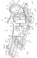
- FIG. 1A is a perspective view
- FIG. 1B is a side view
- FIG. 1C is a plan view, showing an example of mounting a patient placed on a medical device.
- FIG. 4A is a schematic diagram showing a fixed state
- FIG. 4B is a schematic diagram showing a released state, showing an example of a fixed release mechanism provided in the chest unit.
- It is a schematic diagram which shows the operation example of a chest unit.
- the medical device 1 will be described on the assumption that it is used for spinal correction treatment performed before spinal deformity surgery. I do not care.
- spinal deformity surgery requires an incision in the front or back of the spinal column and various operating techniques, making the operation difficult, overloading the patient, and enabling surgery Limited physicians.
- this treatment is performed before spinal deformity surgery.
- the spine is stretched and pulled in the axial direction of the body, and then the chest and waist are moved left and right according to the deformed state of the spine. Correct spinal displacement.
- the lumbar part is first positioned (fixed) and then the chest part is moved in the left-right direction according to the deformed state of the spinal column. It is also possible to move the lumbar region after fixing the chest. Depending on the deformed state of the spinal column, it may be moved in the left-right direction including the legs.
- the treatment performed before this operation is performed using the medical device 1 described below, and then the spinal deformity is performed.
- the medical device 1 shown in FIG. 1 and FIG. 2 is used when correcting the displacement of the spine as described above.
- pre-surgery that is performed before surgery is performed by incising a part of the body, installing a screw, connecting a rod, and operating an operation tool such as a hook. Used for treatment and operated by an orthopedic surgeon (hereinafter referred to as “operator”).
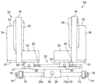
- the medical device 1 includes a base 10 including a holding unit 5 that holds the patient 2 in a prone position, and the base 10 has a substantially rectangular frame 11. Consists of.
- the frame 11 extends in the front-rear direction and extends in the left-right direction with a predetermined interval in front and rear of the pair of left and right vertical rails 13, 13 arranged in parallel and the vertical rails 13, 13. , And horizontal rails 15, 15 arranged in parallel.
- the horizontal rails 15 are slidably attached to the vertical rails 13 as shown by arrows in FIG. 1 via the connecting members 16, and each horizontal rail 15 is movable along the vertical rails 13.
- the fixing member 16 is attached to the connecting member 16 to fix the horizontal rail 15 to the vertical rail 13 or to release the horizontal rail 15 so as to be movable.
- the fixing / releasing mechanism is configured such that a lever 18 having an eccentric cam (not shown) is pivotally supported by the connecting member 16, and the vertical rail 13 is connected to the connecting member 16 by the displacement of the eccentric cam caused by the rotation of the lever 18.
- the connecting member 16 can be fixed to the vertical rail 13 and the connecting member 16 can be released from the vertical rail 13 by clamping the eccentric cam or separating the eccentric cam from the vertical rail 13. Then, after the connecting member 16 is released from the vertical rail 13 and the horizontal rail 15 is slid along the vertical rail 13, the horizontal rail 15 is positioned at an optimal position by fixing the connecting member 16 to the vertical rail 13. It is possible.
- the horizontal rail 15 is fixed to the vertical rail 13 by the rotation of the lever 18.
- the fixing form such as fixing by general screwing is used. It does not matter.
- the holding unit 5 includes a chest unit 5A that holds the chest of the patient 2, a waist unit 5B that holds the patient's waist, and a leg unit 5C that holds the leg of the patient 2.
- the chest unit 5A is attached to the upper part of the horizontal rail 15a arranged at the front part, and the waist unit 5B is bridged between the vertical rails 13 and 13 between the horizontal rails 15 and 15 arranged at the front and rear. Attached. Further, the leg unit 5C is attached to an upper portion of the horizontal rail 15b disposed at the rear portion.
- the chest unit 5 ⁇ / b> A holds a pair of supports 21, 21 that respectively support the left and right breasts of the patient 2, and both shoulders of the patient 2 attached to the support 21. Holding body 23.
- the support 21 is attached to a slider 25 that is slidably attached to the horizontal rail 15a.
- the slider 25 has a through hole 26a into which the horizontal rail 15a is inserted, and is slidably attached to the horizontal rail 15a.
- a slider main body 27 mounted on the pedestal 26.
- the lower surface of the slider body 27 is formed in an arcuate arc shape, and the upper surface of the pedestal 26 has a curved surface formed according to the curvature of the arc.
- the chest unit 5A can be turned with a predetermined curvature by moving the slider body 27 left and right on the pedestal 26, and the chest of the patient 2 can be twisted.
- the pedestal 26 is movable along the horizontal rail 15a, and can move the chest of the patient 2 in the left-right direction.
- a recess 27a is formed on the lower surface of the slider body 27. Between the recess 27a and the base 26, the movement of the slider body 27 and the base 26 is fixed, or the slider body 27 and the base 26 are fixed.
- a fixed release mechanism is provided for movably releasing 26.
- the fixing / releasing mechanism includes two engagements that are vertically overlapped with each other in a square hole 26b that is formed in the vertical direction from the upper surface of the base 26 and communicates with the through hole 26a.
- the members 37a and 37b and the screw 36 for separating the two engaging members 37a and 37b in the vertical direction are provided.
- the lower surface of one engaging member 37a is in contact with the upper surface of the horizontal rail 15a, and the upper surface of the other member 37b is in contact with the concave portion 27a of the slider body 27.
- the screw 36 includes a head portion 36a that functions as a handle and a shaft portion 36b.
- the shaft portion 36b is inserted into a hole 26c formed on the side surface of the base 26. Is done.
- the shaft portion 36b has a tapered shape, and the tip portion of the shaft portion 36b is abutted against the boundary between the two engagement members 37a and 37b, whereby the two engagement members 37a and 37b can be separated.
- the slider main body 27 when the screw 36 is not inserted into the hole 26c, the slider main body 27 is moved by the load of the patient 2 to the other engagement member 37b.
- the slider main body 27 is in contact with the upper surface
- the upper surface of the horizontal rail 15a is in contact with the lower surface of one of the engaging members 37a
- the two engaging members 37a and 37b are in contact with each other.
- the movement of the pedestal 26 is restricted (fixed).
- the pedestal 26 and the slider body 27 are fixed or released by the fixing / releasing mechanism.
- the pedestal 26 and the slider body 27 may be fixed or released by using another fixing / releasing mechanism. Absent.
- long grooves 29 extending in the left-right direction are formed on the left and right sides of the slider body 27, and each support body 21 has a protruding portion 28 that protrudes downward. By being engaged with and attached to the long groove 29, each support body 21 can freely move in the long groove 29.
- the projecting portion 28 is attached so as to sandwich the upper surface of the slider main body 27, and a screw 30 for adjusting the sandwiching force is attached to the side surface of the projecting portion 28. Then, the projecting portion 28 is clamped and fixed by the tightening by the rotation of the screw 30, while the fixing state of the projecting portion 28 to the slider main body 27 is released by releasing the tightening force by the rotation of the screw 30.
- the protrusion 28 can be moved freely. And the position of each support body 21 is adjusted by moving the protrusion part 28 within the range of the long groove 29.
- each support body 21 and 21 is attached to the slider main body 27 so that movement to the left-right direction is carried out, and according to a patient's body shape, each support body 21 and 21 is moved and between support bodies 21 and 21 is carried out. The width is adjusted.
- the holding body 23 is erected on the end portion of the support body 21 and holds the side of the patient 2, and the support body 21 is provided integrally with the support body 21 on the inside thereof.
- An annular body 34 for holding the outside of the shoulder, and the arm of the patient 2 is inserted between the standing body 33 and the annular body 34 to hold the shoulder of the patient 2 around.
- An elastic pad 35 is provided on the upper portion of the support body 21, around the standing body 33, and on the front inner side of the annular body 34 to hold the patient's shoulders and fix the chest.
- the pad 35 is preferably made of a material that can transmit X-rays, and the body of the patient 2 bites into the pad 35, so that there is a slight error in the width between the supports 21 and 21 with respect to the body shape. Even if there is, the chest of the patient 2 is firmly fixed.
- the chest unit 5A can move or turn (twist) in the left-right direction as shown by the arrows in FIG. 5 while holding the patient's chest as shown in FIG.
- An operator performs an operation of twisting the patient's body and an operation of moving in the left-right direction according to the state of the spinal deformity.
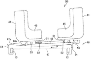
- the waist unit 5 ⁇ / b> B has a pair of support bodies 41, 41 that are formed in a substantially L shape that supports the left and right waists of the patient 2.
- the support body 41 holds the patient's waist.
- the support body 41 is attached to a slider 46 that spans between the vertical rails 13 and 13, and the slider 46 is fixed to the left and right vertical rails 13 and 13, and a pedestal 47 that is attached. And a slider main body 48 attached to the pedestal 47.
- the lower surface of the slider body 48 is formed in an arcuate arc shape, and the upper surface of the pedestal 47 has a curved surface formed according to the curvature of the arc. Further, a concave portion 48a is formed on the lower surface of the slider body 48, and a convex portion 47a fitted to the concave portion 48a is formed on the upper surface of the pedestal 47.
- the slider main body 48 moves in the left-right direction on the pedestal 47. Can be moved (turned).
- the slider 46 also includes a turning mechanism (not shown) that turns the slider body 48 in the left-right direction with respect to the base 47.
- the turning mechanism is, for example, a first screw that is exposed to a part of the convex portion 47 a formed on the pedestal 47, and is screwed with the first screw to the concave portion 48 a of the slider body 48.
- a second screw provided, and the slide main body 48 can be moved by rotation of the second screw.
- a knob 54 for rotating the first screw is provided on the left and right side surfaces of the pedestal 47, and the slide main body 48 rotates the first screw by rotating the knob 54, thereby The screw is rotated, and as shown by an arrow in FIG. 6, the screw moves and turns while sliding in the left-right direction on the pedestal 47.
- the lumbar unit 5B can turn with a predetermined curvature by moving the slider body 48 left and right on the pedestal 26, and can twist the patient's lumbar region.
- the patient's waist is first positioned by the waist unit 5B, and the chest unit 5A and the leg unit 5C are used after the waist is fixed. The patient's spinal correction is performed.
- each support body 41, 41 has a protruding portion 51 that protrudes downward. Since the 51 is engaged with and attached to the long groove 52, each support body 41, 41 can freely move in the long groove 52.
- the projecting portion 51 is attached so as to sandwich the upper surface of the slider body 48, and a screw 53 for adjusting the sandwiching force is attached to the side surface of the projecting portion 51. . Then, the projecting portion 51 is clamped and fixed by the tightening by the rotation of the screw 53, while the fixing state of the projecting portion 51 to the slider main body 48 is released by releasing the tightening force by the rotation of the screw 53.
- the protrusion 51 can be freely moved (FIG. 6).
- each support body 41 and 41 is adjusted by moving the protrusion part 51 within the range of the long groove 52.
- each support body 41 and 41 is attached to the slider main body 48 so that movement to right and left is possible, and according to the patient's 2 body shape, each support body 41 and 41 is moved and between support bodies 41 and 41 is carried out. The width is adjusted.
- the support body 41 is provided with an elastic pad 45 to hold the waist of the patient 2.
- the pad 45 is preferably made of a material that can transmit X-rays, and the body of the patient 2 bites into the pad 45, so that there is a slight error in the width between the support bodies 41 and 41 with respect to the body shape. Even if there is, the waist of the patient 2 is firmly fixed.
- the lumbar unit 5B is capable of turning (twisting) in the left-right direction while holding the lumbar part of the patient 2, and an operation for twisting the lumbar part of the patient 2 by the operator according to the state of spinal deformation. And the patient's waist is positioned and secured.
- the leg unit 5 ⁇ / b> C includes a pair of supports 61, 61 that support the left and right crus of the patient 2, and the crus are held by the support 61.
- the support 61 is attached to a slider 65 that is slidably attached to the horizontal rail 15b.
- the slider 65 is slidably attached to the horizontal rail 15b, and a slider main body 67 that is attached to the pedestal 66. And.
- the lower surface of the slider body 67 is formed in an arcuate arc shape, and the upper surface of the pedestal 66 has a curved surface formed according to the curvature of the arc.
- the leg unit 5C can turn with a predetermined curvature by moving the slider body 67 left and right on the pedestal 66, and can twist the leg of the patient.
- the pedestal 66 is movable along the horizontal rail 15b, and the patient's legs can be moved in the left-right direction (FIG. 8).
- a recess 67a is formed on the lower surface of the slider body 67. Between the recess 67a and the pedestal 66, the movement of the slider body 67 and the pedestal 66 is fixed, or the slider body 67 and the pedestal 66 are movably released. A fixed release mechanism is provided.
- this fixed release mechanism uses the same mechanism as the above-mentioned chest unit 5A, the description is omitted.
- the pedestal 66 and the slider main body 67 are fixed or released by the fixing / releasing mechanism.
- the pedestal 66 and the slider main body 67 may be fixed or released by using another fixing / releasing mechanism. Absent.
- long grooves 69 extending in the left-right direction are formed on the left and right sides of the slider body 67, and each support body 61 has a protrusion 68 protruding downward, and the protrusion 68 is a long groove.
- each support body 61 can freely move in the long groove 69.
- the projecting portion 68 is attached so as to sandwich the upper surface of the slider body 67, and a screw 70 for adjusting the sandwiching force is attached to the side surface of the projecting portion 68. Then, the projecting portion 68 is clamped and fixed by the tightening by the rotation of the screw 70, while the fixing state of the projecting portion 68 to the slider main body 67 is released by releasing the tightening force by the rotation of the screw 70. It is possible to move the protrusion 68 freely.
- each support body 61 is adjusted by moving the protrusion 68 within the range of the long groove 69.
- each support body 61 and 61 is attached to the slider main body 67 so that it can move to right and left, and according to a patient's body shape, each support body 61 and 61 is moved, and the width
- the support 61 includes a plate-like base 62 that holds the front of the lower leg of the patient 2, and a knee of the patient 2 is disposed on the base end side of the base 62.
- An elastic pad 64 a on which the portion is placed is provided, and an annular member 63 is provided on the distal end side of the base body 62 so as to be integrated with the base body 62 and hold the ankle portion of the patient 2.
- An elastic pad 64b is provided inside the annular member 63.
- the pads 64a and 64b are preferably made of a material that can transmit X-rays. The body of the patient 2 bites into the pads 64a and 64b, so that the width between the support bodies 61 and 61 with respect to the body shape. Even if there is some error, the leg (crus) of the patient 2 is firmly fixed.
- the leg unit 5C can be moved or turned (twisted) in the left-right direction while holding the leg of the patient 2, and the operator can change the patient 2 according to the state of spinal deformation.
- An operation of twisting the leg portion and an operation of moving in the left-right direction are performed.
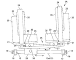
- the medical device 1 is detachably attachable with a pressure correction tool 80 for pressing a part of the spine constituting the spine arranged between the chest unit 5A and the lumbar unit 5B. Provided.
- the pressure correction tool 80 includes an upright body 81 that is attached to the vertical rail 13 and stands in the vertical direction, and an extruded body 85 that is attached to the upright body 81 via a connecting portion 83 and can be extruded in the left-right direction.
- the raising body 81 is detachably provided on the vertical rail 13 via the connecting portion 82, and an elastic pad 87 is provided at the distal end portion of the extruded body 85, and a part of the spine that constitutes the spinal column is provided by the pad 87. The thrust is pressed.
- the extruded body 85 is provided so as to be slidable in the vertical direction via the connecting portion 83 and can be adjusted in height.
- the pad 87 is provided at the tip of a rod-like extruded body 85 extending in the left-right direction, and the extruded body 85 is provided so as to be movable in the left-right direction via the connecting portion 83. The position of can be adjusted.
- this pressure correction tool 80 may be installed in a plurality of places according to the state of spinal deformation.
- the treatment of this embodiment is performed with emphasis on pelvic alignment, and is performed with the lumbar part fixed.
- the waist unit 5B is fixedly attached to the vertical rail 13, and after positioning the patient's waist, the chest unit 5A is moved forward and pulled, and then The spine is corrected by moving the chest unit 5A in the left-right direction according to the state of the spine deformation.
- the patient 2 is placed face down on the chest unit 5A, the waist unit 5B, and the leg unit 5C arranged side by side on the base 10.
- various screws 30, 53, 70 are used to support the chest unit 5 ⁇ / b> A between the supports 21, 21, between the waist unit 5 ⁇ / b> B supports 41, 41, and the leg unit 5 ⁇ / b> C support 61.
- 61 is adjusted so that each support 21, 41, 61 fits the patient 2.
- the waist of the patient 2 is fixed (positioned) using the waist unit 5B, and then the positions of the chest unit 5A and the leg unit 5C are adjusted according to the body shape of the patient 2 so that the body of the patient 2 Fixed.
- the chest unit 5A is moved and held away from the waist unit 5B. As a result, the spine of the patient 2 is pulled.
- the chest unit 5A is turned left and right according to the deformed state of the spinal column. Thereby, only the chest can be pressed in the left-right direction with the patient's 2 waist fixed, and the spinal column can be easily corrected.
- the pressure correction tool 80 is attached between the chest unit 5A and the lumbar unit 5B, and a part of the calculus constituting the spinal column is pressed to correct the spinal column.
- the medical device according to the present embodiment is the same as the medical device according to the first embodiment, in which the waist unit 5B is fixed and the chest unit 5A and the leg unit 5C are close to or away from the waist unit 5B. Whereas the slider 65 of 5B was only swiveled, the waist unit 5B is movable along the vertical rail 13 like the chest unit 5A and the leg unit 5C. It differs in that it can move and turn.
- the structure of the slider 46 of the chest unit 5A of the present embodiment is the same as that of the chest unit 5A or the leg unit 5C, and a description thereof will be omitted.
- the chest unit 5A and the waist unit 5B can be moved relatively in the left-right direction, or the waist can be moved or turned in the left-right direction with the chest fixed. is there. Moreover, within the range of the vertical rail 13, it is possible to move freely while fixing the patient.
- the medical device according to the present embodiment is capable of turning the chest unit 5A, the waist unit 5B, or the leg unit 5C while the medical device according to the first or second embodiment is capable of turning the chest unit 5A and the waist unit.
- 5B or the leg unit 5C is different in that it only moves in the left-right direction.
- the chest unit 5A and the waist unit 5B of this embodiment are realized by integrally fixing the slider main bodies 27 and 67 and the bases 26 and 66 shown in FIG. 3 or FIG. Since other structures are the same, the description thereof is omitted.
- the correction range of the patient is narrowed due to the inability to turn, but the manufacturing cost can be significantly reduced.
- the medical device 1X of the present embodiment is another example of the fixing / releasing mechanism provided in the chest unit 5A and the leg unit 5C of the medical device 1 of the first embodiment.
- the following fixing and releasing mechanism will be described as a fixing and releasing mechanism provided in the chest unit 5A, but may be used as a fixing and releasing mechanism provided in the leg unit 5C.
- the fixing / releasing mechanism of the present embodiment includes two gears 105, 106 that are formed in a vertical direction from the upper surface of the base 26 and disposed in a space 120 that communicates with the through hole 26a. And a screw 110 connected to the gears 105 and 106.
- the gears 105 and 106 include worm gears 105a and 106a and helical gears 105b and 106b arranged on the same axis.
- One worm gear 105 a meshes with the rack gear 101 formed on the lower surface of the slider body 27, and the other worm gear 106 a meshes with the rack gear 102 formed on the upper surface of the base 26.
- the screw 110 includes a head portion 110 a that functions as a handle and a shaft portion 110 b.
- the shaft portion 110 b is inserted into a long hole 121 that extends in the vertical direction and is formed on the side surface of the base 26 that communicates with the space 120.
- a helical gear 109 that meshes with the helical gears 105b and 106b of the gears 105 and 106 is provided at the tip portion.
- the screw 110 is disposed in the elongated hole 121 via a positioning piece 125 disposed on the outer peripheral surface of the shaft portion 110b. By moving the piece 125 in the up and down direction within the elongated hole 121, the screw 110 is screwed. 110 can be moved to a desired position.
- the screw 110 moves upward to engage with the worm gear 105a on the slider body 27 side, and moves downward to engage with the worm gear 106a on the base 26 side.
- the screw 110 moves in one of the upper and lower directions and rotates the head portion 110a to transmit the rotational driving force to one of the worm gears 105a and 106a, thereby passing through the one rack gear 101 and 102.
- the driving force is transmitted and the slider body 27 or the pedestal 26 can be moved.
- the helical gear 109 of the screw 110 may be able to move the screw 110 to a central position where it does not mesh with the helical gears 105b and 106b of the gears 105 and 106. By doing so, it is possible to prevent the slide body 27 and the base 26 from moving due to an erroneous operation by moving the screw 110 to the center position.
- the slider body 27 or the pedestal 26 can be moved via the gears, positioning can be easily performed even after the patient 2 is mounted on the medical device 1. .
- the medical device 1 includes, on the base 10, the chest unit 5 ⁇ / b> A that supports the chest of the patient 2, the waist unit 5 ⁇ / b> B that supports the waist of the patient 2, and the legs of the patient 2.
- the horizontal rail 15 is slidably provided on the vertical rail 13 via a connecting member 16 that moves the chest unit 5A or the leg unit 5C in a first direction that is separated from the waist unit 5B in the horizontal direction.
- sliders 46 and 25 for moving the waist unit 5B or the chest unit 5A in a horizontal direction orthogonal to the first direction.
- the chest unit 5A or the leg unit 5C is provided with a lever 18 as a fixing / releasing mechanism for fixing or releasing the horizontal rail 15 with respect to the vertical rail 13.
- the chest unit 5A or the leg unit 5C is moved and held so as to be separated from the waist unit 5B, and after the patient's spinal column is pulled, the chest unit 5A or the chest unit 5A or By moving or turning the lumbar unit 5B left and right, the spinal column can be easily deformed.
- the medical device 1 is configured with a simple mechanism as described above, can reduce the manufacturing cost without increasing the size, and has good operability when correcting the deformation of the spine.
- the medical device 200 of the present embodiment is an embodiment of the medical device 200 in which the leg unit 5C of the medical device 1 shown in the first embodiment is excluded and the chest unit 5A and the waist unit 5B are simplified.
- the medical device 200 is the same in that the chest unit 5A and the waist unit 5B can be moved in the front-rear direction, but the pair of supports 21, 21 of the chest unit 5A of the first embodiment, and the waist unit While the pair of support bodies 41, 41 of 5B move integrally in the left-right direction, the pair of support bodies 227 of the chest unit 5A of this embodiment and the pair of support bodies 247 of the lumbar unit 5B are in the left-right direction. However, it is different in that it does not have a turning mechanism.
- the medical device 200 of the present embodiment includes a base 220 including a holding unit 210 that holds the patient 2 in the prone position as an example.
- the medical device 200 is used by being placed on a bed device such as an operating table (not shown) that is generally used.
- the medical device 200 is fixed to the bed device.
- the medical device 200 may have any form as long as the medical device 200 can be fixed to the bed device, and a known mechanism is appropriately employed for the fixing mechanism, and the description thereof is omitted. To do.
- the base 220 includes a pair of left and right vertical rails 215 and 215 that extend in the front-rear direction and are arranged in parallel, and a horizontal rail 216 that is bridged between the vertical rails 215 and 215.
- the holding unit 210 includes a chest unit 5A that holds the chest of the patient 2 and a waist unit 5B that holds the waist of the patient 2, and the chest unit 5A is disposed in front of the pair of vertical rails 215 and 215.
- the waist unit 5B is disposed on the substantially same plane behind the chest unit 5A.
- the chest unit 5A includes a base 221 on which the chest of the patient 2 is placed, and a holding unit 225 that is attached to the left and right of the base 221 and holds the side of the chest of the patient 2.
- the base 221 is slidably attached to the vertical rails 215 and 215 via the connecting body 235 so that a flat plate member is bridged between the vertical rails 215 and 215.
- the base 221 includes an extension part 221a extending forward, and the shoulder and face of the patient 2 are placed on the extension part 221a.
- the connecting body 235 is disposed so as to surround the periphery of the vertical rail 215, and a fixing tool 237 for fixing the connecting body 235 to the vertical rail 215 is attached to a side surface of the connecting body 235.
- the fixture 237 includes a rotatable head and a shaft portion extending vertically downward from the head, and is attached by being screwed to a hole (not shown) formed in the side surface of the coupling body 235.
- the connecting body 235 is fixed to the vertical rail 215 by tightening the fixture 237 and bringing the tip of the shaft portion into contact with the side surface of the vertical rail 215.
- the coupling body 235 can freely move with respect to the vertical rail 215 by rotating the head of the fixing tool 237 in the reverse direction to loosen it and separating the tip of the shaft portion from the side surface of the vertical rail 215.
- the fixing tool 237 may be attached to each of the left and right coupling bodies 235, or may be attached to only one of them.
- the holding unit 225 is erected on a pair of pedestals 226 and 226 that are slidably attached in the width (left and right) direction on both the left and right sides of the base body 221, and the chest 2 side (both arms) of the patient 2
- support bodies 227 and 227 for supporting the lower part of the base of the arm (under the armpits), and the left and right support bodies 227 and 227 apply a predetermined pressing force to support both sides of the chest of the patient 2.
- a plate-like member having a size for supporting the side of the chest of the patient 2 is used as the support 227.
- the side of the patient 2 is supported. Since it functions also as a pressing body for pressing the one side of the part, it is not necessary to simply support the chest of the patient 2, and at least the height and strength corresponding to the thickness of the chest of the patient 2 are necessary. The height and strength are appropriately set.
- a protrusion 229 that protrudes inward is formed behind the support 227.
- This protrusion 229 is formed with an inclined surface 229a for gradually narrowing the width between the supports 227, 227 from the center to the rear in the length direction of the support 227, and between the supports 227, 227, The rear width is narrower than the front width.
- the pedestal 226 is provided with an adjustment mechanism for adjusting the installation position of each support 227 with respect to the base body 221 according to the body shape of the patient 2, and this adjustment mechanism is attached to the front and rear upper surfaces of the pedestal 226. .
- the adjustment mechanism is, for example, a fixture 228 having a rotatable head and a shaft extending vertically downward from the head, and is screwed into a hole (not shown) formed on the upper surface of the base 226.
- the pedestal 226 is fixed to the base body 221 by attaching the fixture 228 and bringing the tip of the shaft portion into contact with the upper surface of the base body 221.
- the pedestal 226 can move freely with respect to the base 221 by rotating the fixing tool 228 in the reverse direction to loosen it and separating the tip of the shaft portion from the upper surface of the base 221.
- the waist unit 5B includes a base 241 on which the waist of the patient 2 is placed, and a holding unit 245 that is attached to the left and right of the base 241 and holds the side of the waist of the patient 2.
- the base 241 is slidably attached to the vertical rails 215 and 215 via the connecting body 235 so that a flat plate member is bridged between the vertical rails 215 and 215.
- connection body 235 and the fixing member 237 attached to the connection body 235 have the same structure as the connection body 235 provided in the chest unit 5A, and thus the description thereof is omitted.
- the holding unit 245 is a pair of pedestals 246 and 246 that are slidably attached to the left and right sides of the base 221, and a support 247 that is erected on each pedestal 246 and supports the lumbar side of the patient 2. 247, and the left and right supports 247, 247 apply a predetermined pressing force to support both sides of the waist of the patient 2.
- the support 247 is a plate-like member having a size for supporting the side of the waist of the patient 2, but when performing spinal correction treatment using the medical device 200 of this embodiment, the patient 2 Since it functions also as a pressing body for pressing one side of the patient, it is not necessary to simply support the waist of the patient 2, and at least the height and strength corresponding to the thickness of the patient's waist are required. The height and strength are appropriately set.
- a protrusion 249 protruding inward is formed in front of the support 247.
- This protrusion 249 is formed with an inclined surface 249a that gradually narrows the width between the supports 247 and 247 from the center to the front in the length direction of the support 247, and between the supports 247 and 247, The width is narrower than the rear width.
- the pedestal 246 is provided with an adjustment mechanism for adjusting the installation position of the support 247 with respect to the base body 241 in accordance with the body shape of the patient 2, and this adjustment mechanism is attached to the front and rear upper surfaces of the pedestal 246.
- the adjustment mechanism has the same structure as the fixture 228 provided in the above-described chest unit 5A, description thereof will be omitted.
- the support members 227 and 247 of the chest unit 5A and the waist unit 5B are provided with a predetermined area around the support members 227 and 247 in order to ease contact with the body of the patient 2.
- a buffer material 250 having a thickness is attached.
- the cushioning material 250 is disposed at least in the region of the supports 227 and 247 that come into contact with the body of the patient 2.
- the buffer material 250 may also be disposed on the upper surfaces of the base body 221 and the base body 241. Further, when the supports 227 and 247 are formed of an elastic body, it is not necessary to provide the buffer material 250, and the buffer material 250 is provided as necessary.
- the medical device 200 of the present embodiment is a medical device in which the chest unit 5A that supports the chest of the patient 2 and the waist unit 5B that supports the waist of the patient 2 are arranged side by side on the base 220.
- the waist unit 5B is fixed on the base 220, and the fixture 237 attached to the connecting body 235 provided in the chest unit 5A is loosened, so that the chest unit 5A is moved back and forth. Since it can move freely in the direction, the chest unit 5A can be moved toward or away from the waist unit 5B, and the patient can be easily pulled.
- the medical device 200 fixes the chest unit 5A and the waist unit 5B on the base 220 and loosens the fixture 228, so that the bases 226 and 246 can be freely moved in the width direction of the bases 221 and 241. Since it can move, the chest unit or 5A can easily perform treatment for correcting the deformation of the spine by fixing one of the waist unit 5B and moving the other in the width direction.
- the support members 227 and 247 of the chest unit 5A and the waist unit 5B are provided with the protruding portions 229 and 249, when performing the patient's pulling operation, the body of the patient 2 and the support members 227 and 247 Therefore, the patient 2 can be prevented from slipping with respect to the supports 227 and 247, and the traction operation can be performed reliably.
- the projecting portions 229 and 249 are inclined surfaces 229a and 249a.
- the shape is not limited, and any shape may be used as long as the anti-slip effect can be obtained.
- the protrusions 229 and 249 are provided on the supports 227 and 247 so that the contact pressure between the body of the patient 2 and the supports 227 and 247 is increased when the patient is towing.
- the support bodies 227 and 247 are formed in a curved shape, or the support bodies 227 and 247 are attached to the bases 226 and 246 so as to be rotatable about an axis with respect to the vertical direction. You may make it raise contact pressure by inclining and fixing.
- the patient 2 is placed face down on the chest unit 5A and the waist unit 5B, which are arranged side by side on the base 220.
- the adjustment mechanism adjusts between the holding units 225 of the chest unit 5 ⁇ / b> A and between the holding units 245 of the waist unit 5 ⁇ / b> B so that the supports 227 and 247 fit the patient 2.
- the patient's body is fixed.
- the chest unit 5A and the waist unit 5B are fixed by first fixing (positioning) the waist of the patient 2 using the waist unit 5B, and then adjusting and fixing the position of the chest unit 5A.
- the chest unit 5A is moved and held away from the waist unit 5B. As a result, the spine of the patient 2 is pulled.
- the other of the lumbar unit 5A and the chest unit is pressed against either the left or right direction to correct the spinal column.
- one support body 227, 247 is fixed, the other support body 227, 247 is unfixed, and the other support body 227, 247 is pressed in one direction to perform orthodontic treatment.
- the medical device 200 of the present embodiment can easily perform spinal correction treatment including traction with a simple configuration. Moreover, since it is a simple structure, productivity can be improved easily and the medical device 200 can be manufactured at low cost.
- this embodiment is one form, Comprising: It is not limited to this form.
- each adjustment mechanism of the present embodiment can adopt a known technique even if it is not configured as described above.
- Examples 1 to 5 may be used in appropriate combination.
- the form of the moving mechanism for moving the chest unit 5A and the waist unit 5B in the front-rear direction with respect to the base 220 is not limited to the present embodiment, and a known technique can be adopted.
- a moving mechanism for moving the holding units 225 and 245 in the width direction and a mechanism for fixing or releasing the holding units 225 and 245 with respect to the bases 221 and 241 are not limited to the present embodiment, and a known technique is used. Can be adopted.
Abstract
Priority Applications (4)
| Application Number | Priority Date | Filing Date | Title |
|---|---|---|---|
| CN201780024499.1A CN109310510A (zh) | 2016-04-19 | 2017-04-18 | 医疗装置 |
| JP2018513186A JP6537152B2 (ja) | 2016-04-19 | 2017-04-18 | 医療装置 |
| EP17785970.9A EP3446662A4 (fr) | 2016-04-19 | 2017-04-18 | Dispositif médical |
| US16/094,648 US20190117488A1 (en) | 2016-04-19 | 2017-04-18 | Medical device |
Applications Claiming Priority (2)
| Application Number | Priority Date | Filing Date | Title |
|---|---|---|---|
| JP2016-083917 | 2016-04-19 | ||
| JP2016083917 | 2016-04-19 |
Publications (1)
| Publication Number | Publication Date |
|---|---|
| WO2017183632A1 true WO2017183632A1 (fr) | 2017-10-26 |
Family
ID=60116755
Family Applications (1)
| Application Number | Title | Priority Date | Filing Date |
|---|---|---|---|
| PCT/JP2017/015565 WO2017183632A1 (fr) | 2016-04-19 | 2017-04-18 | Dispositif médical |
Country Status (5)
| Country | Link |
|---|---|
| US (1) | US20190117488A1 (fr) |
| EP (1) | EP3446662A4 (fr) |
| JP (1) | JP6537152B2 (fr) |
| CN (1) | CN109310510A (fr) |
| WO (1) | WO2017183632A1 (fr) |
Cited By (5)
| Publication number | Priority date | Publication date | Assignee | Title |
|---|---|---|---|---|
| CN109512622A (zh) * | 2018-11-20 | 2019-03-26 | 河南省中医院(河南中医药大学第二附属医院) | 一种麻醉科用辅助固定装置 |
| WO2020067470A1 (fr) * | 2018-09-27 | 2020-04-02 | ミズホ株式会社 | Dispositif d'assistance à la chirurgie d'ancrage/de correction de déformation de la colonne vertébrale |
| EP3653179A1 (fr) * | 2018-11-16 | 2020-05-20 | Fundación para la Investigación e Innovación Biosanitaria de Asturias (FINBA) | Dispositif pour la fabrication d'un corset pour le traitement de la scoliose |
| JPWO2021124612A1 (fr) * | 2019-12-16 | 2021-06-24 | ||
| US20210236369A1 (en) * | 2020-02-03 | 2021-08-05 | Alphatec Spine, Inc. | Patient positioning system |
Families Citing this family (10)
| Publication number | Priority date | Publication date | Assignee | Title |
|---|---|---|---|---|
| US10568797B1 (en) * | 2015-11-04 | 2020-02-25 | ScoliWRx, Inc. | Spinal cord and meninges stretching frame and method to prevent and treat the root cause of scoliosis |
| US11160709B2 (en) * | 2016-06-14 | 2021-11-02 | Warsaw Orthopedic, Inc. | Surgical table with movement capabilities of lower body support structures |
| CN111281770A (zh) * | 2020-03-18 | 2020-06-16 | 郑灵芝 | 一种用于妇产科产后护理的康复训练床 |
| CN111449857B (zh) * | 2020-04-16 | 2022-04-08 | 江西省人民医院 | 一种神经外科用康复治疗装置 |
| CN111956383B (zh) * | 2020-08-28 | 2022-07-29 | 王泽昊 | 一种数控气压式骨科牵引器 |
| CN111904687B (zh) * | 2020-09-10 | 2022-08-30 | 赵晓东 | 一种具有夹角可调和自锁功能的骨科牵引装置 |
| CN113350102A (zh) * | 2020-10-12 | 2021-09-07 | 浙江德康医疗器械有限公司 | 脊柱矫形支架 |
| US20230190255A1 (en) * | 2021-12-22 | 2023-06-22 | Globus Medical, Inc. | Patient positioner |
| CN114432081B (zh) * | 2022-02-07 | 2024-04-16 | 中国人民解放军海军军医大学第一附属医院 | 一种骨盆固定装置的使用方法 |
| CN114533478B (zh) * | 2022-03-01 | 2023-01-24 | 南华大学附属第一医院 | 针对肝胆外科术前检查用智能体位矫正设备 |
Citations (8)
| Publication number | Priority date | Publication date | Assignee | Title |
|---|---|---|---|---|
| US4660549A (en) * | 1985-09-12 | 1987-04-28 | Standex International | Adjustable head support for chiropractic table |
| US6007568A (en) * | 1998-08-17 | 1999-12-28 | Harrell; Eric A. | Traction table |
| US6076525A (en) * | 1999-01-28 | 2000-06-20 | Hoffman; Michael D. | Frame for prone surgical positioning |
| US6428497B1 (en) * | 2001-09-01 | 2002-08-06 | Richard A. Crouch | Therapeutic table system |
| JP2004081638A (ja) * | 2002-08-28 | 2004-03-18 | Howa Mach Ltd | 腰痛治療装置 |
| US20040171974A1 (en) * | 2002-12-16 | 2004-09-02 | Cert Health Sciences, Llc | Method and apparatus for therapeutic treatment of back pain |
| JP2007508073A (ja) * | 2003-10-17 | 2007-04-05 | エコール・ポリテクニック・ドゥ・モンレアル | 腹臥位手術の位置決めのためのダイナミック・フレーム |
| JP2012170763A (ja) * | 2011-02-24 | 2012-09-10 | Kochi Univ | 脊椎整復フレーム |
Family Cites Families (4)
| Publication number | Priority date | Publication date | Assignee | Title |
|---|---|---|---|---|
| KR200438814Y1 (ko) * | 2007-08-08 | 2008-03-06 | 아주메딕스 주식회사 | 척추교정기 |
| WO2009076483A1 (fr) * | 2007-12-10 | 2009-06-18 | Scott Spann | Table réglable pour chirurgie orthopédique et techniques pour implanter un implant vertébral |
| CN101559012A (zh) * | 2009-05-15 | 2009-10-21 | 三峡大学 | 便携式腰椎牵引器 |
| KR101453069B1 (ko) * | 2014-06-02 | 2014-10-22 | 주식회사 제이엠텍 | 정형용 교정장치 |
-
2017
- 2017-04-18 EP EP17785970.9A patent/EP3446662A4/fr not_active Withdrawn
- 2017-04-18 WO PCT/JP2017/015565 patent/WO2017183632A1/fr active Application Filing
- 2017-04-18 CN CN201780024499.1A patent/CN109310510A/zh active Pending
- 2017-04-18 US US16/094,648 patent/US20190117488A1/en not_active Abandoned
- 2017-04-18 JP JP2018513186A patent/JP6537152B2/ja active Active
Patent Citations (8)
| Publication number | Priority date | Publication date | Assignee | Title |
|---|---|---|---|---|
| US4660549A (en) * | 1985-09-12 | 1987-04-28 | Standex International | Adjustable head support for chiropractic table |
| US6007568A (en) * | 1998-08-17 | 1999-12-28 | Harrell; Eric A. | Traction table |
| US6076525A (en) * | 1999-01-28 | 2000-06-20 | Hoffman; Michael D. | Frame for prone surgical positioning |
| US6428497B1 (en) * | 2001-09-01 | 2002-08-06 | Richard A. Crouch | Therapeutic table system |
| JP2004081638A (ja) * | 2002-08-28 | 2004-03-18 | Howa Mach Ltd | 腰痛治療装置 |
| US20040171974A1 (en) * | 2002-12-16 | 2004-09-02 | Cert Health Sciences, Llc | Method and apparatus for therapeutic treatment of back pain |
| JP2007508073A (ja) * | 2003-10-17 | 2007-04-05 | エコール・ポリテクニック・ドゥ・モンレアル | 腹臥位手術の位置決めのためのダイナミック・フレーム |
| JP2012170763A (ja) * | 2011-02-24 | 2012-09-10 | Kochi Univ | 脊椎整復フレーム |
Non-Patent Citations (1)
| Title |
|---|
| See also references of EP3446662A4 * |
Cited By (12)
| Publication number | Priority date | Publication date | Assignee | Title |
|---|---|---|---|---|
| WO2020067470A1 (fr) * | 2018-09-27 | 2020-04-02 | ミズホ株式会社 | Dispositif d'assistance à la chirurgie d'ancrage/de correction de déformation de la colonne vertébrale |
| CN112770708A (zh) * | 2018-09-27 | 2021-05-07 | 瑞穗株式会社 | 脊椎变形矫正固定手术辅助装置 |
| JPWO2020067470A1 (ja) * | 2018-09-27 | 2021-09-24 | ミズホ株式会社 | 脊柱変形矯正固定手術補助装置 |
| CN112770708B (zh) * | 2018-09-27 | 2023-10-20 | 瑞穗株式会社 | 脊椎变形矫正固定手术辅助装置 |
| JP7462228B2 (ja) | 2018-09-27 | 2024-04-05 | ミズホ株式会社 | 脊柱変形矯正固定手術補助装置 |
| EP3653179A1 (fr) * | 2018-11-16 | 2020-05-20 | Fundación para la Investigación e Innovación Biosanitaria de Asturias (FINBA) | Dispositif pour la fabrication d'un corset pour le traitement de la scoliose |
| CN109512622A (zh) * | 2018-11-20 | 2019-03-26 | 河南省中医院(河南中医药大学第二附属医院) | 一种麻醉科用辅助固定装置 |
| CN109512622B (zh) * | 2018-11-20 | 2020-08-11 | 河南省中医院(河南中医药大学第二附属医院) | 一种麻醉科用辅助固定装置 |
| JPWO2021124612A1 (fr) * | 2019-12-16 | 2021-06-24 | ||
| JP7310923B2 (ja) | 2019-12-16 | 2023-07-19 | 株式会社島津製作所 | X線撮影用被検体固定具およびx線撮影システム |
| US20210236369A1 (en) * | 2020-02-03 | 2021-08-05 | Alphatec Spine, Inc. | Patient positioning system |
| US11744758B2 (en) * | 2020-02-03 | 2023-09-05 | Alphatec Spine, Inc. | Patient positioning system |
Also Published As
| Publication number | Publication date |
|---|---|
| CN109310510A (zh) | 2019-02-05 |
| JPWO2017183632A1 (ja) | 2019-01-10 |
| US20190117488A1 (en) | 2019-04-25 |
| JP6537152B2 (ja) | 2019-07-03 |
| EP3446662A1 (fr) | 2019-02-27 |
| EP3446662A4 (fr) | 2020-03-11 |
Similar Documents
| Publication | Publication Date | Title |
|---|---|---|
| WO2017183632A1 (fr) | Dispositif médical | |
| CN107753167B (zh) | 一种腰椎牵引床 | |
| KR101030336B1 (ko) | 경추교정기 | |
| CN108578125A (zh) | 一种重症病房用临床固定装置 | |
| KR20210007389A (ko) | 환자치료용 장비 반복사용에 따른 팔·어깨 누적피로와 집중력저하를 개선한 죽지 부위 활동 보조장치 | |
| CN211382039U (zh) | 一种便于调节的骨科临床用牵引架 | |
| CN214968409U (zh) | 肩关节手术专用沙滩椅位手术床 | |
| CN113081628A (zh) | 肩关节手术专用沙滩椅位手术床 | |
| CN202459134U (zh) | 脊柱矫正床 | |
| CN215652359U (zh) | 一种神经介入术中固定头颅下颌辅助装置 | |
| CN208693705U (zh) | 一种可调节腰椎弯度的腰椎穿刺床 | |
| CN211131430U (zh) | 一种麻醉辅助固定装置 | |
| CN111544281B (zh) | 一种多功能骨伤愈合防护护理装置 | |
| CN209966688U (zh) | 一种脊柱侧弯矫正装置 | |
| KR101886679B1 (ko) | 척추 측만증 교정기 | |
| CN207722016U (zh) | 一种骨外科用支撑装置 | |
| CN113648065A (zh) | 一种骨盆骨折复位机器人的夹持器械 | |
| CN213431417U (zh) | 一种骨科关节镜手术辅助装置 | |
| CN205268447U (zh) | 一种预防足下垂器具 | |
| CN114053527B (zh) | 一种适用于picc置管术和动脉穿刺置管术的多点固定装置 | |
| CN219089333U (zh) | 一种检查床托手架 | |
| CN211985736U (zh) | 一种适用于手术的医生座椅 | |
| CN109793636A (zh) | 一种新型小儿科外科手术体位固定器装置 | |
| CN218943772U (zh) | 膝关节镜手术下肢支撑架及手术床 | |
| CN213697718U (zh) | 脊柱打石膏用体位架 |
Legal Events
| Date | Code | Title | Description |
|---|---|---|---|
| WWE | Wipo information: entry into national phase |
Ref document number: 2018513186 Country of ref document: JP |
|
| NENP | Non-entry into the national phase |
Ref country code: DE |
|
| WWE | Wipo information: entry into national phase |
Ref document number: 2017785970 Country of ref document: EP |
|
| ENP | Entry into the national phase |
Ref document number: 2017785970 Country of ref document: EP Effective date: 20181119 |
|
| 121 | Ep: the epo has been informed by wipo that ep was designated in this application |
Ref document number: 17785970 Country of ref document: EP Kind code of ref document: A1 |