以下、本発明の実施の形態を、添付の図面に示した本発明の実施例に基づいて説明する。なお、以下に示す医療装置1はそのまま単独でも用いられるが、一般的には、手術台や治療台上に載置又は固定されて用いられる。また、以下の医療装置1において、図1の左右方向を医療装置の前後方向として便宜的に説明を行う。
Hereinafter, embodiments of the present invention will be described based on examples of the present invention shown in the accompanying drawings. In addition, although the medical apparatus 1 shown below can be used alone as it is, it is generally used by being mounted or fixed on an operating table or treatment table. In the following medical device 1, the left-right direction in FIG. 1 will be described as the front-back direction of the medical device for convenience.
また、以下に示す実施の形態では、医療装置1が脊柱変形の手術を行う前に行われる脊椎の矯正治療に用いられることを前提として説明するが、手術中に上記矯正治療が用いられても構わない。
In the embodiment described below, the medical device 1 will be described on the assumption that it is used for spinal correction treatment performed before spinal deformity surgery. I do not care.
一般的に脊柱変形の手術は、脊柱の前方部又は後方部を切開して、様々な操作手法を駆使する必要があり、手術の難易度が高く、患者に過度の負担がかかるとともに、手術可能な医師が限られる。
In general, spinal deformity surgery requires an incision in the front or back of the spinal column and various operating techniques, making the operation difficult, overloading the patient, and enabling surgery Limited physicians.
本発明は、従来の脊柱手術における経験等を踏まえ、脊柱変形の矯正において、まず、牽引操作を行うことが非常に効果的であることを発見し、以下に示す医療装置1を用いて、脊椎の変位をできる限り矯正する治療を行った上で、体の一部を切開して脊柱変形の手術を行い、その手術上で行う操作をできる限り簡易化し、手術時間を大幅に短縮することで、手術の難易度を低くするとともに患者の身体的負担の軽減化を図るものである。また、この治療は、患者をうつ伏せにした状態で、脊柱の変位を矯正するものである。
In the present invention, based on experience in conventional spinal column surgery, etc., it was first discovered that traction operation is very effective in correcting spinal deformity, and using the medical device 1 shown below, By performing treatment to correct as much displacement as possible, incising a part of the body and performing spinal deformity surgery, simplifying the operations performed on the surgery as much as possible, and greatly shortening the operation time It is intended to reduce the difficulty of the operation and reduce the physical burden on the patient. This treatment also corrects the spinal displacement while the patient is lying down.
この治療では、一例として脊柱変形の手術を行う前に行われ、まず、脊柱を体の軸方向に伸ばし牽引した後、脊柱の変形状態に応じて、胸部、腰部を左右方向に移動させることで脊柱の変位を矯正する。以下に示す第1実施例における治療では、まず腰部を位置決め(固定)した上で、胸部を脊柱の変形状態に応じて左右方向に移動させるものであるが、胸部と腰部を左右方向に相対的に移動させたり、胸部を固定した上で腰部を移動させても構わない。なお、脊柱の変形状態によっては、脚部も含めて左右方向に移動させても構わない。
As an example, this treatment is performed before spinal deformity surgery. First, the spine is stretched and pulled in the axial direction of the body, and then the chest and waist are moved left and right according to the deformed state of the spine. Correct spinal displacement. In the treatment in the first embodiment shown below, the lumbar part is first positioned (fixed) and then the chest part is moved in the left-right direction according to the deformed state of the spinal column. It is also possible to move the lumbar region after fixing the chest. Depending on the deformed state of the spinal column, it may be moved in the left-right direction including the legs.
本実施形態形態において、この手術前に行われる治療は、以下に説明する医療装置1を用いて行われ、その後、脊柱変形の手術が行われる。
In the present embodiment, the treatment performed before this operation is performed using the medical device 1 described below, and then the spinal deformity is performed.
(第1実施例)
図1及び図2に示す医療装置1は、上述したように脊柱の変位を矯正する際に使用され、特に、脊柱側弯症、脊柱後弯症、前弯性異常などの胸郭部脊髄や腰部脊髄または腰仙骨脊髄変形をもった患者に対して、体の一部を切開してスクリューを設置するとともにロッドを連結させて、フック等の操作具を操作して行う手術の前に行われる手術前の治療に用いられ、整形外科医(以下、「操作者」という。)によって操作される。
(First embodiment)
The medical device 1 shown in FIG. 1 and FIG. 2 is used when correcting the displacement of the spine as described above. For patients with lumbo-sacral spinal deformity, pre-surgery that is performed before surgery is performed by incising a part of the body, installing a screw, connecting a rod, and operating an operation tool such as a hook. Used for treatment and operated by an orthopedic surgeon (hereinafter referred to as “operator”).
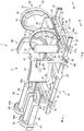
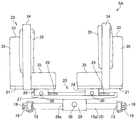
医療装置1は、図1及び図2に示すように、患者2を腹臥位にて保持する保持部5を備えた基台10を備え、この基台10は、略長方形状のフレーム枠11で構成される。
As shown in FIGS. 1 and 2, the medical device 1 includes a base 10 including a holding unit 5 that holds the patient 2 in a prone position, and the base 10 has a substantially rectangular frame 11. Consists of.
フレーム枠11は、前後方向に延在し、平行に配置される左右一対の縦レール13、13と、縦レール13、13の前方及び後方に所定の間隔を有して左右方向に延在し、平行に配置される横レール15、15と、を備える。
The frame 11 extends in the front-rear direction and extends in the left-right direction with a predetermined interval in front and rear of the pair of left and right vertical rails 13, 13 arranged in parallel and the vertical rails 13, 13. , And horizontal rails 15, 15 arranged in parallel.
横レール15は、連結部材16を介して図1中矢印に示すように摺動可能に縦レール13に取り付けられ、各横レール15は、縦レール13に沿って移動可能である。
The horizontal rails 15 are slidably attached to the vertical rails 13 as shown by arrows in FIG. 1 via the connecting members 16, and each horizontal rail 15 is movable along the vertical rails 13.
この連結部材16には、縦レール13に対して横レール15を固定、又は横レール15を移動可能に解放する固定解放機構が取り付けられている。この固定解放機構は、例えば、図示しない偏芯カムを有するレバー18が連結部材16に軸支されて構成され、レバー18の回転による偏芯カムの変位によって連結部材16との間で縦レール13を挟持し、又は偏芯カムを縦レール13から離反させることで、連結部材16を縦レール13に固定・縦レール13から連結部材16を解放可能である。そして、縦レール13から連結部材16を解放して縦レール13に沿って横レール15をスライドさせた後、連結部材16を縦レール13に固定することで横レール15を最適な位置に位置決めすることが可能である。
The fixing member 16 is attached to the connecting member 16 to fix the horizontal rail 15 to the vertical rail 13 or to release the horizontal rail 15 so as to be movable. For example, the fixing / releasing mechanism is configured such that a lever 18 having an eccentric cam (not shown) is pivotally supported by the connecting member 16, and the vertical rail 13 is connected to the connecting member 16 by the displacement of the eccentric cam caused by the rotation of the lever 18. The connecting member 16 can be fixed to the vertical rail 13 and the connecting member 16 can be released from the vertical rail 13 by clamping the eccentric cam or separating the eccentric cam from the vertical rail 13. Then, after the connecting member 16 is released from the vertical rail 13 and the horizontal rail 15 is slid along the vertical rail 13, the horizontal rail 15 is positioned at an optimal position by fixing the connecting member 16 to the vertical rail 13. It is possible.
なお、本実施形態ではレバー18の回転動作によって、横レール15を縦レール13に固定するようになっているが、例えば、一般的なねじ止めによる固定等、その固定形態はどのような形態であっても構わない。
In this embodiment, the horizontal rail 15 is fixed to the vertical rail 13 by the rotation of the lever 18. However, for example, the fixing form such as fixing by general screwing is used. It does not matter.
保持部5は、患者2の胸部を保持する胸部ユニット5Aと、患者の腰部を保持する腰部ユニット5Bと、患者2の脚部を保持する脚部ユニット5Cと、を備えている。
The holding unit 5 includes a chest unit 5A that holds the chest of the patient 2, a waist unit 5B that holds the patient's waist, and a leg unit 5C that holds the leg of the patient 2.
胸部ユニット5Aは、前方部に配置される横レール15aの上部に取り付けられ、腰部ユニット5Bは、前後に配置される横レール15、15の間であって縦レール13、13間に架け渡されて取り付けられる。また、脚部ユニット5Cは、後方部に配置される横レール15bの上部に取り付けられる。
The chest unit 5A is attached to the upper part of the horizontal rail 15a arranged at the front part, and the waist unit 5B is bridged between the vertical rails 13 and 13 between the horizontal rails 15 and 15 arranged at the front and rear. Attached. Further, the leg unit 5C is attached to an upper portion of the horizontal rail 15b disposed at the rear portion.
胸部ユニット5Aは、図1及び図3に示すように、患者2の左右の胸をそれぞれ支持する一対の支持体21、21と、この支持体21に取り付けられ患者2の両肩回りを保持する保持体23と、を備えている。
As shown in FIGS. 1 and 3, the chest unit 5 </ b> A holds a pair of supports 21, 21 that respectively support the left and right breasts of the patient 2, and both shoulders of the patient 2 attached to the support 21. Holding body 23.
支持体21は、横レール15aに摺動可能に取り付けられるスライダ25に取り付けられ、このスライダ25は、横レール15aが挿入される貫通孔26aを有し、この横レール15aに摺動可能に取り付けられる台座26と、この台座26上に取り付けられるスライダ本体27と、を備えている。
The support 21 is attached to a slider 25 that is slidably attached to the horizontal rail 15a. The slider 25 has a through hole 26a into which the horizontal rail 15a is inserted, and is slidably attached to the horizontal rail 15a. And a slider main body 27 mounted on the pedestal 26.
スライダ本体27の下面は、弓型の円弧状に形成され、台座26の上面は、この円弧の曲率にしたがって形成された曲面を有する。
The lower surface of the slider body 27 is formed in an arcuate arc shape, and the upper surface of the pedestal 26 has a curved surface formed according to the curvature of the arc.
そして、胸部ユニット5Aは、このスライダ本体27を台座26上において左右に移動させることで所定の曲率で旋回可能となっており、患者2の胸部をひねることが可能である。また、台座26は、横レール15aに沿って移動可能となっており、患者2の胸部を左右方向に移動可能である。
The chest unit 5A can be turned with a predetermined curvature by moving the slider body 27 left and right on the pedestal 26, and the chest of the patient 2 can be twisted. The pedestal 26 is movable along the horizontal rail 15a, and can move the chest of the patient 2 in the left-right direction.
また、図4に示すように、スライダ本体27の下面には凹部27aが形成され、この凹部27aと台座26の間には、スライダ本体27と台座26の移動を固定、又はスライダ本体27と台座26を移動可能に解放する固定解放機構が設けられている。
As shown in FIG. 4, a recess 27a is formed on the lower surface of the slider body 27. Between the recess 27a and the base 26, the movement of the slider body 27 and the base 26 is fixed, or the slider body 27 and the base 26 are fixed. A fixed release mechanism is provided for movably releasing 26.
この固定解放機構は、例えば、図4に示すように、台座26の上面から鉛直方向に形成され貫通孔26aと連絡する角孔26b内に鉛直方向に重ね合されて配置される2つの係合部材37a、37bと、この2つの係合部材37a、37bを鉛直方向に離反させるネジ36と、を備えている。
For example, as shown in FIG. 4, the fixing / releasing mechanism includes two engagements that are vertically overlapped with each other in a square hole 26b that is formed in the vertical direction from the upper surface of the base 26 and communicates with the through hole 26a. The members 37a and 37b and the screw 36 for separating the two engaging members 37a and 37b in the vertical direction are provided.
一方の係合部材37aの下面は横レール15aの上面と接触し、他方の部材37bの上面はスライダ本体27の凹部27aと接触して配置される。
The lower surface of one engaging member 37a is in contact with the upper surface of the horizontal rail 15a, and the upper surface of the other member 37b is in contact with the concave portion 27a of the slider body 27.
また、ネジ36は、図4(a)に示すように、取手として機能する頭部36aと軸部36bとを具備し、この軸部36bは、台座26の側面に形成された孔26cに挿入される。軸部36bは、先細り形状となっており、その先端部が2つの係合部材37a、37bの境界に突き当てられることによって、2つの係合部材37a、37bを分離することが可能である。
As shown in FIG. 4A, the screw 36 includes a head portion 36a that functions as a handle and a shaft portion 36b. The shaft portion 36b is inserted into a hole 26c formed on the side surface of the base 26. Is done. The shaft portion 36b has a tapered shape, and the tip portion of the shaft portion 36b is abutted against the boundary between the two engagement members 37a and 37b, whereby the two engagement members 37a and 37b can be separated.
このように構成された固定解放機構によれば、図4(a)に示すように、ネジ36を孔26cに挿入しない場合、患者2の荷重によって、スライダ本体27が他方の係合部材37bの上面と接触するとともに、横レール15aの上面が一方の係合部材37aの下面と接触し、さらに、2つの係合部材37a、37bが接触することで、部材同士の接触抵抗により、スライダ本体27と台座26の移動が規制(固定)される。
According to the fixing / releasing mechanism configured as described above, as shown in FIG. 4A, when the screw 36 is not inserted into the hole 26c, the slider main body 27 is moved by the load of the patient 2 to the other engagement member 37b. The slider main body 27 is in contact with the upper surface, the upper surface of the horizontal rail 15a is in contact with the lower surface of one of the engaging members 37a, and the two engaging members 37a and 37b are in contact with each other. The movement of the pedestal 26 is restricted (fixed).
一方、図4(b)に示すように、ネジ36が孔26cに挿入され、その先端部が2つの係合部材37a、37bの境界に突き当てられると、2つの係合部材37a、37bが上下に離反することで、係合部材37a、37b同士の接触抵抗が低くなり、スライダ本体27を左右に移動させたり、台座26を横レール15aに沿って左右に移動させることが可能である。
On the other hand, as shown in FIG. 4B, when the screw 36 is inserted into the hole 26c and its tip is abutted against the boundary between the two engaging members 37a and 37b, the two engaging members 37a and 37b are By separating up and down, the contact resistance between the engaging members 37a and 37b is lowered, and the slider body 27 can be moved to the left and right, and the pedestal 26 can be moved to the left and right along the horizontal rail 15a.
なお、本実施形態では、上記固定解放機構によって台座26及びスライダ本体27を固定又は解放しているが、他の固定解放機構を用いて、台座26とスライダ本体27を固定又は解放しても構わない。
In this embodiment, the pedestal 26 and the slider body 27 are fixed or released by the fixing / releasing mechanism. However, the pedestal 26 and the slider body 27 may be fixed or released by using another fixing / releasing mechanism. Absent.
また、図3に示すように、スライダ本体27の左右には、左右方向に延びる長溝29が形成され、各支持体21には、下方に突出する突出部28を有し、この突出部28が長溝29に係合して取り付けられることによって、各支持体21は、長溝29内を自由に移動することが可能である。
As shown in FIG. 3, long grooves 29 extending in the left-right direction are formed on the left and right sides of the slider body 27, and each support body 21 has a protruding portion 28 that protrudes downward. By being engaged with and attached to the long groove 29, each support body 21 can freely move in the long groove 29.
また、突出部28は、スライダ本体27の上面を挟持するようにして取り付けられており、突出部28の側面には、この挟持力を調整するネジ30が取り付けられている。そして、ネジ30の回転による締付によって突出部28がスライダ本体27を挟持して固定される一方、ネジ30の回転による締付力の解放によって突出部28によるスライダ本体27への固定状態を解き、突出部28を自由に移動させることが可能である。そして、突出部28を長溝29の範囲内で移動することで、各支持体21の位置が調整される。
Further, the projecting portion 28 is attached so as to sandwich the upper surface of the slider main body 27, and a screw 30 for adjusting the sandwiching force is attached to the side surface of the projecting portion 28. Then, the projecting portion 28 is clamped and fixed by the tightening by the rotation of the screw 30, while the fixing state of the projecting portion 28 to the slider main body 27 is released by releasing the tightening force by the rotation of the screw 30. The protrusion 28 can be moved freely. And the position of each support body 21 is adjusted by moving the protrusion part 28 within the range of the long groove 29.
このように各支持体21、21は、左右方向に移動可能にスライダ本体27に取り付けられており、患者の体型に応じて、各支持体21、21が移動されて支持体21、21間の幅が調整される。
Thus, each support body 21 and 21 is attached to the slider main body 27 so that movement to the left-right direction is carried out, and according to a patient's body shape, each support body 21 and 21 is moved and between support bodies 21 and 21 is carried out. The width is adjusted.
図1に示すように、保持体23は、支持体21の端部に立設し患者2の脇を保持する立設体33と、その内側に支持体21と一体的に設けられ患者2の肩の外側を保持する環状体34と、を備え、この立設体33と環状体34の間に患者2の腕が挿入されて患者2の肩回りが保持される。
As shown in FIG. 1, the holding body 23 is erected on the end portion of the support body 21 and holds the side of the patient 2, and the support body 21 is provided integrally with the support body 21 on the inside thereof. An annular body 34 for holding the outside of the shoulder, and the arm of the patient 2 is inserted between the standing body 33 and the annular body 34 to hold the shoulder of the patient 2 around.
支持体21上部、立設体33の周囲、環状体34の前方内側には、弾性を有するパッド35が設けられ、患者の肩回りが保持されるとともに胸部が固定される。このパッド35は、好適には、X線が透過可能な材料で製作されることが好ましく、パッド35に患者2の体が食い込むことで、体型に対する支持体21、21間の幅に多少の誤差があってもしっかりと患者2の胸部が固定される。
An elastic pad 35 is provided on the upper portion of the support body 21, around the standing body 33, and on the front inner side of the annular body 34 to hold the patient's shoulders and fix the chest. The pad 35 is preferably made of a material that can transmit X-rays, and the body of the patient 2 bites into the pad 35, so that there is a slight error in the width between the supports 21 and 21 with respect to the body shape. Even if there is, the chest of the patient 2 is firmly fixed.
このようにして胸部ユニット5Aは、図5に示すように、患者の胸部を保持しつつ、図5中矢印に示すように、左右方向に移動、又は旋回(ひねる)可能となっており、操作者によって、脊椎変形の状態に応じて、患者の体をひねる操作と左右方向に移動させる操作が行われる。
In this way, the chest unit 5A can move or turn (twist) in the left-right direction as shown by the arrows in FIG. 5 while holding the patient's chest as shown in FIG. An operator performs an operation of twisting the patient's body and an operation of moving in the left-right direction according to the state of the spinal deformity.
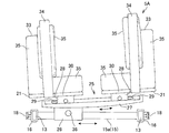
次に、腰部ユニット5Bは、図1、図2及び図6に示すように、患者2の左右の腰をそれぞれ支持する略L字状に形成された一対の支持体41、41を対向配置して備え、この支持体41によって患者の腰回りは保持される。
Next, as shown in FIGS. 1, 2, and 6, the waist unit 5 </ b> B has a pair of support bodies 41, 41 that are formed in a substantially L shape that supports the left and right waists of the patient 2. The support body 41 holds the patient's waist.
図6に示すように、支持体41は、縦レール13、13間に架け渡されるスライダ46に取り付けられ、このスライダ46は、左右の縦レール13、13に固定されて取り付けられる台座47と、この台座47に取り付けられたスライダ本体48と、を備えている。
As shown in FIG. 6, the support body 41 is attached to a slider 46 that spans between the vertical rails 13 and 13, and the slider 46 is fixed to the left and right vertical rails 13 and 13, and a pedestal 47 that is attached. And a slider main body 48 attached to the pedestal 47.
スライダ本体48の下面は、弓型の円弧状に形成され、台座47の上面は、この円弧の曲率にしたがって形成された曲面を有する。また、スライダ本体48の下面には凹部48aが形成され、台座47の上面には、この凹部48aと嵌合される凸部47aが形成されており、スライダ本体48は、台座47上を左右方向に移動(旋回)可能である。
The lower surface of the slider body 48 is formed in an arcuate arc shape, and the upper surface of the pedestal 47 has a curved surface formed according to the curvature of the arc. Further, a concave portion 48a is formed on the lower surface of the slider body 48, and a convex portion 47a fitted to the concave portion 48a is formed on the upper surface of the pedestal 47. The slider main body 48 moves in the left-right direction on the pedestal 47. Can be moved (turned).
また、スライダ46は、台座47に対してスライダ本体48を左右方向に旋回させる図示しない旋回機構を備えている。旋回機構は、図示しないが、例えば、台座47に形成される凸部47aの一部に露出して設けられる第1のスクリューと、この第1のスクリューと螺合しスライダ本体48の凹部48aに設けられる第2のスクリューと、を備え、この第2のスクリューの回転によってスライド本体48を移動可能である。
The slider 46 also includes a turning mechanism (not shown) that turns the slider body 48 in the left-right direction with respect to the base 47. Although not shown, the turning mechanism is, for example, a first screw that is exposed to a part of the convex portion 47 a formed on the pedestal 47, and is screwed with the first screw to the concave portion 48 a of the slider body 48. A second screw provided, and the slide main body 48 can be moved by rotation of the second screw.
また、台座47の左右側面には、当該第1のスクリュを回転するつまみ54が設けられており、スライド本体48は、このつまみ54の回転により第1のスクリューを回転させることで、第2のスクリューを回転させ、図6中矢印に示すように、台座47上を左右方向に摺動しつつ移動し旋回する。
Further, a knob 54 for rotating the first screw is provided on the left and right side surfaces of the pedestal 47, and the slide main body 48 rotates the first screw by rotating the knob 54, thereby The screw is rotated, and as shown by an arrow in FIG. 6, the screw moves and turns while sliding in the left-right direction on the pedestal 47.
そして、腰部ユニット5Bは、このスライダ本体48が台座26上を左右に移動することで所定の曲率で旋回可能となっており、患者の腰部をひねることが可能である。
The lumbar unit 5B can turn with a predetermined curvature by moving the slider body 48 left and right on the pedestal 26, and can twist the patient's lumbar region.
なお、本実施形態では、骨盤アライメントを重視して行われるため、まず、この腰部ユニット5Bによって、患者の腰部が位置決めされ、腰部が固定された後に、胸部ユニット5Aや脚部ユニット5Cが用いられて患者の脊椎矯正が行われる。
In this embodiment, since the pelvic alignment is emphasized, the patient's waist is first positioned by the waist unit 5B, and the chest unit 5A and the leg unit 5C are used after the waist is fixed. The patient's spinal correction is performed.
また、図6に示すように、スライダ本体48の左右には、左右方向に延びる長溝52が形成され、各支持体41、41には、下方に突出する突出部51を有し、この突出部51が長溝52に係合して取り付けられることによって、各支持体41、41は、長溝52内を自由に移動することが可能である。
As shown in FIG. 6, long grooves 52 extending in the left-right direction are formed on the left and right sides of the slider body 48, and each support body 41, 41 has a protruding portion 51 that protrudes downward. Since the 51 is engaged with and attached to the long groove 52, each support body 41, 41 can freely move in the long groove 52.
また、突出部51は、スライダ本体48の上面を挟持するようにして取り付けられており、突出部51の側面には、この挟持力を調整するネジ53が取り付けられている。。そして、ネジ53の回転による締付によって突出部51がスライダ本体48を挟持して固定される一方、ネジ53の回転による締付力の解放によって突出部51によるスライダ本体48への固定状態を解き、突出部51を自由に移動させることが可能である(図6)。
Further, the projecting portion 51 is attached so as to sandwich the upper surface of the slider body 48, and a screw 53 for adjusting the sandwiching force is attached to the side surface of the projecting portion 51. . Then, the projecting portion 51 is clamped and fixed by the tightening by the rotation of the screw 53, while the fixing state of the projecting portion 51 to the slider main body 48 is released by releasing the tightening force by the rotation of the screw 53. The protrusion 51 can be freely moved (FIG. 6).
そして、突出部51を長溝52の範囲内で移動することで、各支持体41、41の位置が調整される。
And the position of each support body 41 and 41 is adjusted by moving the protrusion part 51 within the range of the long groove 52.
このように各支持体41、41は、左右に移動可能にスライダ本体48に取り付けられており、患者2の体型に応じて、各支持体41、41が移動されて支持体41、41間の幅が調整される。
Thus, each support body 41 and 41 is attached to the slider main body 48 so that movement to right and left is possible, and according to the patient's 2 body shape, each support body 41 and 41 is moved and between support bodies 41 and 41 is carried out. The width is adjusted.
支持体41には、弾性を有するパッド45が設けられ、患者2の腰部が保持される。このパッド45は、好適には、X線が透過可能な材料で製作されることが好ましく、パッド45に患者2の体が食い込むことで、体型に対する支持体41、41間の幅に多少の誤差があってもしっかりと患者2の腰部が固定される。
The support body 41 is provided with an elastic pad 45 to hold the waist of the patient 2. The pad 45 is preferably made of a material that can transmit X-rays, and the body of the patient 2 bites into the pad 45, so that there is a slight error in the width between the support bodies 41 and 41 with respect to the body shape. Even if there is, the waist of the patient 2 is firmly fixed.
このようにして腰部ユニット5Bは、患者2の腰部を保持しつつ、左右方向に旋回(ひねる)可能となっており、操作者によって、脊椎変形の状態に応じて、患者2の腰部をひねる操作が行われ、患者の腰部が位置決めされて固定される。
In this way, the lumbar unit 5B is capable of turning (twisting) in the left-right direction while holding the lumbar part of the patient 2, and an operation for twisting the lumbar part of the patient 2 by the operator according to the state of spinal deformation. And the patient's waist is positioned and secured.
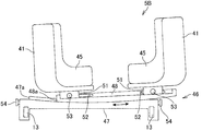
次に、図7及び図8に示すように、脚部ユニット5Cは、患者2の左右下腿部を支持する一対の支持体61、61を備え、この支持体61によって下腿部が保持される。支持体61は、横レール15bに摺動可能に取り付けられるスライダ65に取り付けられ、このスライダ65は、横レール15bに摺動可能に取り付けられる台座66と、この台座66上に取り付けられるスライダ本体67と、を備えている。
Next, as shown in FIGS. 7 and 8, the leg unit 5 </ b> C includes a pair of supports 61, 61 that support the left and right crus of the patient 2, and the crus are held by the support 61. The The support 61 is attached to a slider 65 that is slidably attached to the horizontal rail 15b. The slider 65 is slidably attached to the horizontal rail 15b, and a slider main body 67 that is attached to the pedestal 66. And.
スライダ本体67の下面は、弓型の円弧状に形成され、台座66の上面は、この円弧の曲率にしたがって形成された曲面を有する。
The lower surface of the slider body 67 is formed in an arcuate arc shape, and the upper surface of the pedestal 66 has a curved surface formed according to the curvature of the arc.
そして、脚部ユニット5Cは、このスライダ本体67が台座66上を左右に移動することで所定の曲率で旋回可能となっており、患者の脚部をひねることが可能である。また、台座66は、横レール15bに沿って移動可能となっており、患者の脚部を左右方向に移動可能である(図8)。
The leg unit 5C can turn with a predetermined curvature by moving the slider body 67 left and right on the pedestal 66, and can twist the leg of the patient. The pedestal 66 is movable along the horizontal rail 15b, and the patient's legs can be moved in the left-right direction (FIG. 8).
また、スライダ本体67の下面には凹部67aが形成され、この凹部67aと台座66の間には、スライダ本体67と台座66の移動を固定、又はスライダ本体67と台座66を移動可能に解放する固定解放機構が設けられている。
A recess 67a is formed on the lower surface of the slider body 67. Between the recess 67a and the pedestal 66, the movement of the slider body 67 and the pedestal 66 is fixed, or the slider body 67 and the pedestal 66 are movably released. A fixed release mechanism is provided.
なお、この固定解放機構は、上述した胸部ユニット5Aと同じ機構を用いるためその説明は省略する。また、本実施形態では、上記固定解放機構によって台座66及びスライダ本体67を固定又は解放しているが、他の固定解放機構を用いて、台座66とスライダ本体67を固定又は解放しても構わない。
In addition, since this fixed release mechanism uses the same mechanism as the above-mentioned chest unit 5A, the description is omitted. In this embodiment, the pedestal 66 and the slider main body 67 are fixed or released by the fixing / releasing mechanism. However, the pedestal 66 and the slider main body 67 may be fixed or released by using another fixing / releasing mechanism. Absent.
また、図8に示すように、スライダ本体67の左右には左右方向に延びる長溝69が形成され、各支持体61には、下方に突出する突出部68を有し、この突出部68が長溝69に係合して取り付けられることによって、各支持体61は、長溝69内を自由に移動することが可能である。
As shown in FIG. 8, long grooves 69 extending in the left-right direction are formed on the left and right sides of the slider body 67, and each support body 61 has a protrusion 68 protruding downward, and the protrusion 68 is a long groove. By being engaged with and attached to 69, each support body 61 can freely move in the long groove 69.
また、突出部68は、スライダ本体67の上面を挟持するようにして取り付けられており、突出部68の側面には、この挟持力を調整するネジ70が取り付けられている。そして、ネジ70の回転による締付によって突出部68がスライダ本体67を挟持して固定される一方、ネジ70の回転による締付力の解放によって突出部68によるスライダ本体67への固定状態を解き、突出部68を自由に移動させることが可能である。
Further, the projecting portion 68 is attached so as to sandwich the upper surface of the slider body 67, and a screw 70 for adjusting the sandwiching force is attached to the side surface of the projecting portion 68. Then, the projecting portion 68 is clamped and fixed by the tightening by the rotation of the screw 70, while the fixing state of the projecting portion 68 to the slider main body 67 is released by releasing the tightening force by the rotation of the screw 70. It is possible to move the protrusion 68 freely.
そして、突出部68を長溝69の範囲内で移動することで、各支持体61の位置が調整される。
And the position of each support body 61 is adjusted by moving the protrusion 68 within the range of the long groove 69.
このように各支持体61、61は、左右に移動可能にスライダ本体67に取り付けられており、患者の体型に応じて、各支持体61、61が移動されて支持体61、61間の幅が調整される。
Thus, each support body 61 and 61 is attached to the slider main body 67 so that it can move to right and left, and according to a patient's body shape, each support body 61 and 61 is moved, and the width | variety between support bodies 61 and 61 is supported. Is adjusted.
支持体61は、図1、図7及び図8に示すように、患者2の下腿部の前方を保持する板状の基体62を備え、この基体62の基端側には患者2の膝部分が載置される弾性を有するパッド64aが設けられ、この基体62の先端側には基体62と一体的に設けられ、患者2の足首部分を保持する環状部材63が設けられる。また、環状部材63の内側には、弾性を有するパッド64bが設けられる。このパッド64a、64bは、好適には、X線が透過可能な材料で製作されることが好ましく、パッド64a、64bに患者2の体が食い込むことで、体型に対する支持体61、61間の幅に多少の誤差があってもしっかりと患者2の脚部(下腿部)が固定される。
As shown in FIGS. 1, 7, and 8, the support 61 includes a plate-like base 62 that holds the front of the lower leg of the patient 2, and a knee of the patient 2 is disposed on the base end side of the base 62. An elastic pad 64 a on which the portion is placed is provided, and an annular member 63 is provided on the distal end side of the base body 62 so as to be integrated with the base body 62 and hold the ankle portion of the patient 2. An elastic pad 64b is provided inside the annular member 63. The pads 64a and 64b are preferably made of a material that can transmit X-rays. The body of the patient 2 bites into the pads 64a and 64b, so that the width between the support bodies 61 and 61 with respect to the body shape. Even if there is some error, the leg (crus) of the patient 2 is firmly fixed.
このようにして脚部ユニット5Cは、患者2の脚部を保持しつつ、左右方向に移動、又は旋回(ひねる)可能となっており、操作者によって、脊椎変形の状態に応じて、患者2の脚部をひねる操作と左右方向に移動させる操作が行われる。
In this way, the leg unit 5C can be moved or turned (twisted) in the left-right direction while holding the leg of the patient 2, and the operator can change the patient 2 according to the state of spinal deformation. An operation of twisting the leg portion and an operation of moving in the left-right direction are performed.
また、図1に示すように、医療装置1には、胸部ユニット5Aと腰部ユニット5Bの間に配置される脊柱を構成する一部の推骨を押圧するための圧迫矯正具80が着脱可能に設けられる。
Further, as shown in FIG. 1, the medical device 1 is detachably attachable with a pressure correction tool 80 for pressing a part of the spine constituting the spine arranged between the chest unit 5A and the lumbar unit 5B. Provided.
圧迫矯正具80は、縦レール13に取り付けられ鉛直方向に起立する起立体81と、起立体81に連結部83を介して取り付けられ左右方向に押し出し可能な押出体85と、を備える。
The pressure correction tool 80 includes an upright body 81 that is attached to the vertical rail 13 and stands in the vertical direction, and an extruded body 85 that is attached to the upright body 81 via a connecting portion 83 and can be extruded in the left-right direction.
起立体81は、連結部82を介して縦レール13に着脱可能に設けられ、押出体85の先端部には、弾性を有するパッド87が設けられ、このパッド87により脊柱を構成する一部の推骨が押圧される。
The raising body 81 is detachably provided on the vertical rail 13 via the connecting portion 82, and an elastic pad 87 is provided at the distal end portion of the extruded body 85, and a part of the spine that constitutes the spinal column is provided by the pad 87. The thrust is pressed.
そして、連結部83を介して押出体85は、上下方向に摺動可能に設けられ高さ調整可能となっている。また、パッド87は、左右方向に延在する棒状の押出体85の先端に設けられ、この押出体85は、連結部83を介して左右方向に移動可能に設けられておりパッド87の水平方向の位置を調整可能となっている。
Further, the extruded body 85 is provided so as to be slidable in the vertical direction via the connecting portion 83 and can be adjusted in height. The pad 87 is provided at the tip of a rod-like extruded body 85 extending in the left-right direction, and the extruded body 85 is provided so as to be movable in the left-right direction via the connecting portion 83. The position of can be adjusted.
なお、この圧迫矯正具80は、脊椎変形の状態に応じて複数個所に設置されても構わない。
In addition, this pressure correction tool 80 may be installed in a plurality of places according to the state of spinal deformation.
このように本実施形態の治療は、骨盤アライメントを重視して行われるものであって、腰部を固定して行われる。
Thus, the treatment of this embodiment is performed with emphasis on pelvic alignment, and is performed with the lumbar part fixed.
したがって、本実施形態の医療装置1は、腰部ユニット5Bが縦レール13に固定して取り付けられており、患者の腰部を位置決めした後に、胸部ユニット5Aが前方へと移動されて牽引され、その後、脊椎変形の状態に応じて、胸部ユニット5Aを左右方向に移動させることで脊椎の矯正が行われる。
Therefore, in the medical device 1 of the present embodiment, the waist unit 5B is fixedly attached to the vertical rail 13, and after positioning the patient's waist, the chest unit 5A is moved forward and pulled, and then The spine is corrected by moving the chest unit 5A in the left-right direction according to the state of the spine deformation.
次に、医療装置1を用いた具体的使用例について説明する。
Next, a specific use example using the medical device 1 will be described.
まず、基台10上に並べて配置された、胸部ユニット5Aと、腰部ユニット5Bと、脚部ユニット5Cに患者2をうつ伏せ状態で載置する。その際、患者2の体型に応じて、各種ねじ30、53、70により、胸部ユニット5Aの支持体21、21間、腰部ユニット5Bの支持体41、41間、脚部ユニット5Cの支持体61、61間が調整されて、各支持体21、41、61が患者2にフィットするように調整される。
First, the patient 2 is placed face down on the chest unit 5A, the waist unit 5B, and the leg unit 5C arranged side by side on the base 10. At that time, depending on the body shape of the patient 2, various screws 30, 53, 70 are used to support the chest unit 5 </ b> A between the supports 21, 21, between the waist unit 5 </ b> B supports 41, 41, and the leg unit 5 </ b> C support 61. , 61 is adjusted so that each support 21, 41, 61 fits the patient 2.
次に、腰部ユニット5Bを用いて、患者2の腰部が固定(位置決め)され、その後、患者2の体型に応じて、胸部ユニット5Aと脚部ユニット5Cの位置が調整されて患者2の体が固定される。
Next, the waist of the patient 2 is fixed (positioned) using the waist unit 5B, and then the positions of the chest unit 5A and the leg unit 5C are adjusted according to the body shape of the patient 2 so that the body of the patient 2 Fixed.
次に、胸部ユニット5Aを、腰部ユニット5Bから離反させるように移動させ保持する。これにより患者2の脊柱が牽引される。
Next, the chest unit 5A is moved and held away from the waist unit 5B. As a result, the spine of the patient 2 is pulled.
次に、脊柱の変形状態に応じて胸部ユニット5Aを左右に旋回させる。これにより、患者2の腰部が固定された状態で胸部のみを左右方向に押圧することができ、容易に脊柱の矯正が行える。
Next, the chest unit 5A is turned left and right according to the deformed state of the spinal column. Thereby, only the chest can be pressed in the left-right direction with the patient's 2 waist fixed, and the spinal column can be easily corrected.
なお、脊柱の変形状によっては、胸部ユニット5Aと腰部ユニット5Bの間に圧迫矯正具80を取り付け、脊柱を構成する一部の推骨を押圧し、脊柱の矯正が行われる。
Depending on the deformed shape of the spinal column, the pressure correction tool 80 is attached between the chest unit 5A and the lumbar unit 5B, and a part of the calculus constituting the spinal column is pressed to correct the spinal column.
(第2実施例)
次に医療装置の第2実施例を説明する。
(Second embodiment)
Next, a second embodiment of the medical device will be described.
本実施例の医療装置は、第1実施例の医療装置が、腰部ユニット5Bを固定して、胸部ユニット5Aと脚部ユニット5Cを腰部ユニット5Bに対して近接又は離反可能であって、腰部ユニット5Bのスライダ65は旋回のみであったのに対して、腰部ユニット5Bが、胸部ユニット5Aおよび脚部ユニット5Cと同様に、縦レール13に沿って移動可能であって、スライダ46は左右方向の移動と旋回が可能である点で異なる。
The medical device according to the present embodiment is the same as the medical device according to the first embodiment, in which the waist unit 5B is fixed and the chest unit 5A and the leg unit 5C are close to or away from the waist unit 5B. Whereas the slider 65 of 5B was only swiveled, the waist unit 5B is movable along the vertical rail 13 like the chest unit 5A and the leg unit 5C. It differs in that it can move and turn.
本実施例の胸部ユニット5Aのスライダ46の構造は、胸部ユニット5A又は脚部ユニット5Cと同じ構造が用いられるため、その説明は省略する。
The structure of the slider 46 of the chest unit 5A of the present embodiment is the same as that of the chest unit 5A or the leg unit 5C, and a description thereof will be omitted.
このように、腰部ユニット5Bを構成することにより、胸部ユニット5Aと腰部ユニット5Bを左右方向に相対的に移動させたり、胸部を固定した上で腰部を左右方向に移動又は旋回させることが可能である。また、縦レール13の範囲内において、患者を固定したまま自由に移動することが可能である。
In this way, by configuring the waist unit 5B, the chest unit 5A and the waist unit 5B can be moved relatively in the left-right direction, or the waist can be moved or turned in the left-right direction with the chest fixed. is there. Moreover, within the range of the vertical rail 13, it is possible to move freely while fixing the patient.
(第3実施例)
次に医療装置の第3実施例を説明する。
(Third embodiment)
Next, a third embodiment of the medical device will be described.
本実施例の医療装置は、第1又は第2実施例の医療装置が、胸部ユニット5A、腰部ユニット5B、又は脚部ユニット5Cを旋回可能であったのに対して、胸部ユニット5A、腰部ユニット5B、又は脚部ユニット5Cが、左右方向の移動のみである点で異なる。
The medical device according to the present embodiment is capable of turning the chest unit 5A, the waist unit 5B, or the leg unit 5C while the medical device according to the first or second embodiment is capable of turning the chest unit 5A and the waist unit. 5B or the leg unit 5C is different in that it only moves in the left-right direction.
本実施例の胸部ユニット5A、腰部ユニット5Bは、図3又は図6に示すスライダ本体27、67と台座26、66とを一体的に固定することで実現される。なお、その他の構造は同じであるため、その説明は省略する。
The chest unit 5A and the waist unit 5B of this embodiment are realized by integrally fixing the slider main bodies 27 and 67 and the bases 26 and 66 shown in FIG. 3 or FIG. Since other structures are the same, the description thereof is omitted.
このように、胸部ユニット5A、腰部ユニット5B、又は脚部ユニット5Cを構成することにより、旋回できないことにより患者の矯正範囲は狭まるものの、製造コストを大幅に低減することが可能である。
As described above, by configuring the chest unit 5A, the waist unit 5B, or the leg unit 5C, the correction range of the patient is narrowed due to the inability to turn, but the manufacturing cost can be significantly reduced.
(第4実施例)
次に医療装置1の第4実施例を図9を用いて説明する。
(Fourth embodiment)
Next, a fourth embodiment of the medical device 1 will be described with reference to FIG.
本実施例の医療装置1Xは、第1実施例の医療装置1の胸部ユニット5Aと脚部ユニット5Cに設けられている固定解放機構の他の一例である。以下の固定解放機構は、胸部ユニット5Aに設けられる固定解放機構を説明するが、脚部ユニット5Cに設けられる固定解放機構として用いても構わない。
The medical device 1X of the present embodiment is another example of the fixing / releasing mechanism provided in the chest unit 5A and the leg unit 5C of the medical device 1 of the first embodiment. The following fixing and releasing mechanism will be described as a fixing and releasing mechanism provided in the chest unit 5A, but may be used as a fixing and releasing mechanism provided in the leg unit 5C.
本実施例の固定解放機構は、図9に示すように、台座26の上面から鉛直方向に形成され貫通孔26aと連絡する空間120内に配置される2つのギア105、106と、この2つのギア105、106と接続されるネジ110と、を備えている。また、ギア105、106は、同軸上に配置されたウォームギア105a、106aと、はすばギア105b、106bを備えている。
As shown in FIG. 9, the fixing / releasing mechanism of the present embodiment includes two gears 105, 106 that are formed in a vertical direction from the upper surface of the base 26 and disposed in a space 120 that communicates with the through hole 26a. And a screw 110 connected to the gears 105 and 106. The gears 105 and 106 include worm gears 105a and 106a and helical gears 105b and 106b arranged on the same axis.
一方のウォームギア105aは、スライダ本体27の下面に形成されるラックギア101と噛合し、他方のウォームギア106aは、台座26の上面に形成されるラックギア102と噛合する。
One worm gear 105 a meshes with the rack gear 101 formed on the lower surface of the slider body 27, and the other worm gear 106 a meshes with the rack gear 102 formed on the upper surface of the base 26.
また、ネジ110は、取手として機能する頭部110aと軸部110bとを具備し、この軸部110bは、空間120に連絡する台座26の側面に形成された鉛直方向に延びる長孔121に挿入され、その先端部には、各ギア105、106のはすばギア105b、106bと噛合するはすばギア109が設けられている。
The screw 110 includes a head portion 110 a that functions as a handle and a shaft portion 110 b. The shaft portion 110 b is inserted into a long hole 121 that extends in the vertical direction and is formed on the side surface of the base 26 that communicates with the space 120. A helical gear 109 that meshes with the helical gears 105b and 106b of the gears 105 and 106 is provided at the tip portion.
また、ネジ110は、軸部110bの外周面に配置された位置決め用のコマ125を介して長孔121に配置されており、コマ125を長孔121内で上下方向に移動することで、ネジ110を所望の位置に移動可能となっている。
Further, the screw 110 is disposed in the elongated hole 121 via a positioning piece 125 disposed on the outer peripheral surface of the shaft portion 110b. By moving the piece 125 in the up and down direction within the elongated hole 121, the screw 110 is screwed. 110 can be moved to a desired position.
そして、ネジ110は、上方へ移動することで、スライダ本体27側のウォームギア105a噛み合う一方で、下方へ移動することで、台座26側のウォームギア106aと噛み合う。
The screw 110 moves upward to engage with the worm gear 105a on the slider body 27 side, and moves downward to engage with the worm gear 106a on the base 26 side.
したがって、ネジ110は、上下いずれか一方の方向に移動し、頭部110aを回転することにより、その回転駆動力を一方のウォームギア105a、106aに伝達することで、一方のラックギア101、102を介して駆動力が伝達され、スライダ本体27又は台座26を移動することが可能である。
Therefore, the screw 110 moves in one of the upper and lower directions and rotates the head portion 110a to transmit the rotational driving force to one of the worm gears 105a and 106a, thereby passing through the one rack gear 101 and 102. Thus, the driving force is transmitted and the slider body 27 or the pedestal 26 can be moved.
なお、ネジ110のはすばギア109が、ギア105、106のはすばギア105b、106bと噛み合わない中央の位置にネジ110を移動することが可能としてもよい。このようにすれば、ネジ110を中央の位置に移動することで、誤操作によるスライド本体27と台座26の移動を防止することができる。
It should be noted that the helical gear 109 of the screw 110 may be able to move the screw 110 to a central position where it does not mesh with the helical gears 105b and 106b of the gears 105 and 106. By doing so, it is possible to prevent the slide body 27 and the base 26 from moving due to an erroneous operation by moving the screw 110 to the center position.
このように本実施例では、ギア類を介してスライダ本体27又は台座26を移動することができるようにしたため、患者2を医療装置1に装着した後でも位置決めを容易に行うことが可能である。
Thus, in this embodiment, since the slider body 27 or the pedestal 26 can be moved via the gears, positioning can be easily performed even after the patient 2 is mounted on the medical device 1. .
以上に説明したように、本実施形態の医療装置1は、基台10上に、患者2の胸部を支持する胸部ユニット5Aと、患者2の腰部を支持する腰部ユニット5Bと、患者2の脚部を支持する脚部ユニット5Cと、を並べて配置し、胸部ユニット5A、腰部ユニット5B、及び脚部ユニット5Cによって患者2を腹臥位に保持して脊椎関節を治療するための医療装置1であって、腰部ユニット5Bに対して胸部ユニット5A又は脚部ユニット5Cを水平方向に離反する第1の方向に移動する連結部材16を介して縦レール13に摺動可能に設けられた横レール15と、腰部ユニット5B又は胸部ユニット5Aを前記第1の方向と直交する水平方向に移動するスライダ46、25と、を備えている。
As described above, the medical device 1 according to the present embodiment includes, on the base 10, the chest unit 5 </ b> A that supports the chest of the patient 2, the waist unit 5 </ b> B that supports the waist of the patient 2, and the legs of the patient 2. A medical device 1 for treating a spinal joint with the chest unit 5A, the lumbar unit 5B, and the leg unit 5C holding the patient 2 in the prone position by arranging the leg unit 5C supporting the head side by side. The horizontal rail 15 is slidably provided on the vertical rail 13 via a connecting member 16 that moves the chest unit 5A or the leg unit 5C in a first direction that is separated from the waist unit 5B in the horizontal direction. And sliders 46 and 25 for moving the waist unit 5B or the chest unit 5A in a horizontal direction orthogonal to the first direction.
また、胸部ユニット5A又は脚部ユニット5Cには、縦レール13に対して横レール15を固定、又は解放する固定解放機構としてのレバー18を備えている。
Further, the chest unit 5A or the leg unit 5C is provided with a lever 18 as a fixing / releasing mechanism for fixing or releasing the horizontal rail 15 with respect to the vertical rail 13.
このような医療装置1において、胸部ユニット5A若しくは脚部ユニット5Cを、腰部ユニット5Bから離反させるように移動させ保持し、患者の脊柱を牽引した後、脊柱の変形状態に応じて胸部ユニット5A又は腰部ユニット5Bを左右に移動又は旋回させることで、容易に脊柱の変形を矯正することができる。
In such a medical device 1, the chest unit 5A or the leg unit 5C is moved and held so as to be separated from the waist unit 5B, and after the patient's spinal column is pulled, the chest unit 5A or the chest unit 5A or By moving or turning the lumbar unit 5B left and right, the spinal column can be easily deformed.
また、医療装置1は、上述したように簡易な機構で構成され、大型化を図ることなく製造コストの低減化を図れるとともに、脊椎の変形を矯正する際の操作性が良い。
Further, the medical device 1 is configured with a simple mechanism as described above, can reduce the manufacturing cost without increasing the size, and has good operability when correcting the deformation of the spine.
(第5実施例)
次に、医療装置の第5実施例を図10乃至図12を用いて説明する。
(5th Example)
Next, a fifth embodiment of the medical device will be described with reference to FIGS.
本実施例の医療装置200は、第1実施例に示す医療装置1の脚部ユニット5Cを除くとともに、胸部ユニット5A及び腰部ユニット5Bを簡易化した医療装置200の実施例である。
The medical device 200 of the present embodiment is an embodiment of the medical device 200 in which the leg unit 5C of the medical device 1 shown in the first embodiment is excluded and the chest unit 5A and the waist unit 5B are simplified.
具体的には、医療装置200は、胸部ユニット5Aと腰部ユニット5Bを前後方向に移動可能である点で同じものの、第1実施例の胸部ユニット5Aの一対の支持体21、21や、腰部ユニット5Bの一対の支持体41、41は左右方向に一体的に移動するのに対して、本実施例の胸部ユニット5Aの一対の支持体227や、腰部ユニット5Bの一対の支持体247は左右方向に単独で移動する点で異なるとともに、回旋機構を備えていない点で異なる。
Specifically, the medical device 200 is the same in that the chest unit 5A and the waist unit 5B can be moved in the front-rear direction, but the pair of supports 21, 21 of the chest unit 5A of the first embodiment, and the waist unit While the pair of support bodies 41, 41 of 5B move integrally in the left-right direction, the pair of support bodies 227 of the chest unit 5A of this embodiment and the pair of support bodies 247 of the lumbar unit 5B are in the left-right direction. However, it is different in that it does not have a turning mechanism.
図10及び図11に示すように、本実施例の医療装置200は、一例として、患者2を腹臥位にて保持する保持部210を備えた基台220を備えている。この医療装置200は、一般的に用いられる図示しない手術台等の寝台装置の上に載置して使用される。なお、医療装置200は寝台装置に固定されるが、寝台装置に医療装置200を固定できればどのような形態でもよく、その固定機構は公知の技術が適宜採用されるものであってその説明は省略する。
As shown in FIGS. 10 and 11, the medical device 200 of the present embodiment includes a base 220 including a holding unit 210 that holds the patient 2 in the prone position as an example. The medical device 200 is used by being placed on a bed device such as an operating table (not shown) that is generally used. The medical device 200 is fixed to the bed device. However, the medical device 200 may have any form as long as the medical device 200 can be fixed to the bed device, and a known mechanism is appropriately employed for the fixing mechanism, and the description thereof is omitted. To do.
基台220は、前後方向に延在し、平行に配置される左右一対の縦レール215、215と、縦レール215、215間に架け渡される横レール216と、を備える。
The base 220 includes a pair of left and right vertical rails 215 and 215 that extend in the front-rear direction and are arranged in parallel, and a horizontal rail 216 that is bridged between the vertical rails 215 and 215.
保持部210は、患者2の胸部を保持する胸部ユニット5Aと、患者2の腰部を保持する腰部ユニット5Bと、を備え、胸部ユニット5Aは、一対の縦レール215、215の前方部に配置され、腰部ユニット5Bは、この胸部ユニット5Aの後方に略同一平面上に配置される。
The holding unit 210 includes a chest unit 5A that holds the chest of the patient 2 and a waist unit 5B that holds the waist of the patient 2, and the chest unit 5A is disposed in front of the pair of vertical rails 215 and 215. The waist unit 5B is disposed on the substantially same plane behind the chest unit 5A.
胸部ユニット5Aは、患者2の胸部が載置される基体221と、この基体221の左右に取り付けられ患者2の胸部側方を保持する保持ユニット225と、を備えている。
The chest unit 5A includes a base 221 on which the chest of the patient 2 is placed, and a holding unit 225 that is attached to the left and right of the base 221 and holds the side of the chest of the patient 2.
基体221は、平板状の部材が縦レール215、215間に架け渡されるようにして連結体235を介して各縦レール215、215に摺動可能に取り付けられている。この基体221は前方に延出する延出部221aを備え、この延出部221aには、患者2の肩や顔が載置される。
The base 221 is slidably attached to the vertical rails 215 and 215 via the connecting body 235 so that a flat plate member is bridged between the vertical rails 215 and 215. The base 221 includes an extension part 221a extending forward, and the shoulder and face of the patient 2 are placed on the extension part 221a.
また、連結体235は、縦レール215の周縁を囲むように配置され、この連結体235の側面には、連結体235を縦レール215に固定するための固定具237が取り付けられている。
The connecting body 235 is disposed so as to surround the periphery of the vertical rail 215, and a fixing tool 237 for fixing the connecting body 235 to the vertical rail 215 is attached to a side surface of the connecting body 235.
固定具237は、図示しないが、回転可能な頭部と、この頭部から鉛直下方に延びる軸部とを備え、連結体235の側面に形成される図示しない孔部にねじ結合されて取り付けられ、固定具237を締め付けて軸部の先端部を縦レール215の側面に接触させることで、縦レール215に対して連結体235が固定される。なお、固定具237の頭部を逆回転させて緩め、軸部の先端部を縦レール215の側面から離反させることで、連結体235は縦レール215に対して自由に移動することができる。また、固定具237は、左右の連結体235にそれぞれ取り付けられても良いし、どちらか一方にのみ取り付けられても良い。
Although not shown, the fixture 237 includes a rotatable head and a shaft portion extending vertically downward from the head, and is attached by being screwed to a hole (not shown) formed in the side surface of the coupling body 235. The connecting body 235 is fixed to the vertical rail 215 by tightening the fixture 237 and bringing the tip of the shaft portion into contact with the side surface of the vertical rail 215. In addition, the coupling body 235 can freely move with respect to the vertical rail 215 by rotating the head of the fixing tool 237 in the reverse direction to loosen it and separating the tip of the shaft portion from the side surface of the vertical rail 215. Moreover, the fixing tool 237 may be attached to each of the left and right coupling bodies 235, or may be attached to only one of them.
また、保持ユニット225は、基体221の左右両側に幅(左右)方向に摺動可能に取り付けられる一対の台座226、226と、各台座226に立設され、患者2の胸部側方(両腕のつけ根の下方(脇の下))を支持する支持体227、227と、を備え、左右の支持体227、227により所定の押圧力を加えて患者2の胸部両側が支持される。
In addition, the holding unit 225 is erected on a pair of pedestals 226 and 226 that are slidably attached in the width (left and right) direction on both the left and right sides of the base body 221, and the chest 2 side (both arms) of the patient 2 And support bodies 227 and 227 for supporting the lower part of the base of the arm (under the armpits), and the left and right support bodies 227 and 227 apply a predetermined pressing force to support both sides of the chest of the patient 2.
支持体227は、患者2の胸部側方を支持するための大きさを有する板状の部材が用いられるが、本実施形態の医療装置200を用いて脊椎矯正治療を行う際に患者2の側部片側を押圧するための押圧体としても機能するため、単に患者2の胸部を支持できればよいものではなく、少なくとも患者2の胸部の厚み分の高さや強度が必要であり、この支持体227の高さや強度は適宜設定される。
As the support 227, a plate-like member having a size for supporting the side of the chest of the patient 2 is used. When the spinal correction treatment is performed using the medical device 200 of the present embodiment, the side of the patient 2 is supported. Since it functions also as a pressing body for pressing the one side of the part, it is not necessary to simply support the chest of the patient 2, and at least the height and strength corresponding to the thickness of the chest of the patient 2 are necessary. The height and strength are appropriately set.
また、支持体227の後方には、内側に突出する突出部229が形成されている。この突出部229は支持体227の長さ方向において中央部から後方にかけて徐々に支持体227、227間の幅を狭めるための傾斜面229aを有して形成され、支持体227、227間は、後方の幅が前方の幅に対して狭くなっている。
Further, a protrusion 229 that protrudes inward is formed behind the support 227. This protrusion 229 is formed with an inclined surface 229a for gradually narrowing the width between the supports 227, 227 from the center to the rear in the length direction of the support 227, and between the supports 227, 227, The rear width is narrower than the front width.
また、台座226には、患者2の体型に応じて基体221に対する各支持体227の設置位置を調整するための調整機構が設けられており、この調整機構は、台座226の前後上面に取り付けられる。
Further, the pedestal 226 is provided with an adjustment mechanism for adjusting the installation position of each support 227 with respect to the base body 221 according to the body shape of the patient 2, and this adjustment mechanism is attached to the front and rear upper surfaces of the pedestal 226. .
調整機構は、例えば、回転可能な頭部と、この頭部から鉛直下方に延びる軸部とを備えた固定具228であり、台座226の上面に形成される図示しない孔部にねじ結合されて取り付けられ、固定具228を締め付けて軸部の先端部を基体221の上面に接触させることで、基体221に対して台座226が固定される。なお、固定具228を逆方向に回転させて緩め、軸部の先端部を基体221の上面から離反させることで、台座226は基体221に対して自由に移動することができる。
The adjustment mechanism is, for example, a fixture 228 having a rotatable head and a shaft extending vertically downward from the head, and is screwed into a hole (not shown) formed on the upper surface of the base 226. The pedestal 226 is fixed to the base body 221 by attaching the fixture 228 and bringing the tip of the shaft portion into contact with the upper surface of the base body 221. The pedestal 226 can move freely with respect to the base 221 by rotating the fixing tool 228 in the reverse direction to loosen it and separating the tip of the shaft portion from the upper surface of the base 221.
腰部ユニット5Bは、患者2の腰部が載置される基体241と、この基体241の左右に取り付けられ患者2の腰部側方を保持する保持ユニット245と、を備えている。
The waist unit 5B includes a base 241 on which the waist of the patient 2 is placed, and a holding unit 245 that is attached to the left and right of the base 241 and holds the side of the waist of the patient 2.
基体241は、平板状の部材が縦レール215、215間に架け渡されるようにして連結体235を介して各縦レール215、215に摺動可能に取り付けられている。
The base 241 is slidably attached to the vertical rails 215 and 215 via the connecting body 235 so that a flat plate member is bridged between the vertical rails 215 and 215.
なお、連結体235及び連結体235に取付られる固定具237は、胸部ユニット5Aに設けられている連結体235と同じ構造であるため、その説明は省略する。
Note that the connection body 235 and the fixing member 237 attached to the connection body 235 have the same structure as the connection body 235 provided in the chest unit 5A, and thus the description thereof is omitted.
また、保持ユニット245は、基体221の左右両側に幅方向に摺動可能に取り付けられる一対の台座246、246と、各台座246に立設され、患者2の腰部側方を支持する支持体247、247と、を備え、左右の支持体247、247により所定の押圧力を加えて患者2の腰部両側が支持される。
The holding unit 245 is a pair of pedestals 246 and 246 that are slidably attached to the left and right sides of the base 221, and a support 247 that is erected on each pedestal 246 and supports the lumbar side of the patient 2. 247, and the left and right supports 247, 247 apply a predetermined pressing force to support both sides of the waist of the patient 2.
また、支持体247は、患者2の腰部側方を支持するための大きさを有する板状の部材が用いられるが、本実施形態の医療装置200を用いて脊椎矯正治療を行う際に患者2の側部片側を押圧するための押圧体としても機能するため、単に患者2の腰部を支持できればよいものではなく、少なくとも患者の腰部の厚み分の高さや強度が必要であり、この支持体227の高さや強度は適宜設定される。
In addition, the support 247 is a plate-like member having a size for supporting the side of the waist of the patient 2, but when performing spinal correction treatment using the medical device 200 of this embodiment, the patient 2 Since it functions also as a pressing body for pressing one side of the patient, it is not necessary to simply support the waist of the patient 2, and at least the height and strength corresponding to the thickness of the patient's waist are required. The height and strength are appropriately set.
また、支持体247の前方には、内側に突出する突出部249が形成されている。この突出部249は支持体247の長さ方向において中央部から前方にかけて徐々に支持体247、247間の幅を狭める傾斜面249aを有して形成され、支持体247、247間は、前方の幅が後方の幅に対して狭くなっている。
Further, a protrusion 249 protruding inward is formed in front of the support 247. This protrusion 249 is formed with an inclined surface 249a that gradually narrows the width between the supports 247 and 247 from the center to the front in the length direction of the support 247, and between the supports 247 and 247, The width is narrower than the rear width.
また、台座246には、患者2の体型に応じて基体241に対する支持体247の設置位置を調整するための調整機構が設けられており、この調整機構は、台座246の前後上面に取り付けられる。
Also, the pedestal 246 is provided with an adjustment mechanism for adjusting the installation position of the support 247 with respect to the base body 241 in accordance with the body shape of the patient 2, and this adjustment mechanism is attached to the front and rear upper surfaces of the pedestal 246.
調整機構は、上述した胸部ユニット5Aに設けられている固定具228と同じ構造であるため、その説明は省略する。
Since the adjustment mechanism has the same structure as the fixture 228 provided in the above-described chest unit 5A, description thereof will be omitted.
また、図12に示すように、胸部ユニット5A及び腰部ユニット5Bの支持体227、247には、患者2の体との接触を緩和するために、その支持体227、247の周囲には所定の厚みを有する緩衝材250が取り付けられる。緩衝材250は、少なくとも患者2の体と接触する支持体227、247の領域に配置される。
In addition, as shown in FIG. 12, the support members 227 and 247 of the chest unit 5A and the waist unit 5B are provided with a predetermined area around the support members 227 and 247 in order to ease contact with the body of the patient 2. A buffer material 250 having a thickness is attached. The cushioning material 250 is disposed at least in the region of the supports 227 and 247 that come into contact with the body of the patient 2.
なお、緩衝材250は、基体221及び基体241の上面にも配置しても構わない。また、支持体227、247を弾性体で形成した場合には、緩衝材250を設ける必要はなく、緩衝材250は必要に応じて設けられる。
The buffer material 250 may also be disposed on the upper surfaces of the base body 221 and the base body 241. Further, when the supports 227 and 247 are formed of an elastic body, it is not necessary to provide the buffer material 250, and the buffer material 250 is provided as necessary.
以上に説明したように、本実施例の医療装置200は、患者2の胸部を支持する胸部ユニット5Aと、前記患者2の腰部を支持する腰部ユニット5Bを、基台220上に並べて配置した医療装置200であって、前記腰部ユニット5Bを基台220上に固定し、前記胸部ユニット5Aに設けられている連結体235に取り付けられる固定具237を緩めておくことで、前記胸部ユニット5Aを前後方向に自由に移動できるため、前記腰部ユニット5Bに対して前記胸部ユニット5Aを近接又は離反する方向に移動することができ、患者の牽引動作を容易に行うことができる。また、医療装置200は、前記胸部ユニット5Aと前記腰部ユニット5Bを基台220上に固定し、固定具228を緩めておくことで、台座226、246を基体221、241の幅方向に自由に移動できるため、前記胸部ユニット又5Aは前記腰部ユニット5Bの一方を固定して他方を幅方向に移動することで、脊椎の変形を矯正する治療を容易に行うことができる。
As described above, the medical device 200 of the present embodiment is a medical device in which the chest unit 5A that supports the chest of the patient 2 and the waist unit 5B that supports the waist of the patient 2 are arranged side by side on the base 220. In the apparatus 200, the waist unit 5B is fixed on the base 220, and the fixture 237 attached to the connecting body 235 provided in the chest unit 5A is loosened, so that the chest unit 5A is moved back and forth. Since it can move freely in the direction, the chest unit 5A can be moved toward or away from the waist unit 5B, and the patient can be easily pulled. The medical device 200 fixes the chest unit 5A and the waist unit 5B on the base 220 and loosens the fixture 228, so that the bases 226 and 246 can be freely moved in the width direction of the bases 221 and 241. Since it can move, the chest unit or 5A can easily perform treatment for correcting the deformation of the spine by fixing one of the waist unit 5B and moving the other in the width direction.
また、胸部ユニット5A及び腰部ユニット5Bの支持体227、247には、突出部229、249が設けられているため、患者の牽引動作を行う際に、患者2の体と支持体227、247との接触圧力を容易に高められることから、支持体227、247に対する患者2の体の滑りが防止され、牽引動作を確実に行うことが可能である。なお、本実施例では突出部229、249を傾斜面229a、249aとしたが、その形状は限定されるものではなく、滑り止め効果を得られればどのような形態であっても構わない。
Further, since the support members 227 and 247 of the chest unit 5A and the waist unit 5B are provided with the protruding portions 229 and 249, when performing the patient's pulling operation, the body of the patient 2 and the support members 227 and 247 Therefore, the patient 2 can be prevented from slipping with respect to the supports 227 and 247, and the traction operation can be performed reliably. In this embodiment, the projecting portions 229 and 249 are inclined surfaces 229a and 249a. However, the shape is not limited, and any shape may be used as long as the anti-slip effect can be obtained.
また、本実施例では、支持体227、247に突出部229、249を設けることで、患者の牽引動作を行う際に、患者2の体と支持体227、247との接触圧力を高めるようにしているが、例えば、支持体227、247を湾曲して形成したり、支持体227、247を鉛直方向に対する軸回りに回転可能に台座226、246に取り付け、支持体227、247を所定の角度傾けて固定することで接触圧力を高めるようにしても構わない。
Further, in this embodiment, the protrusions 229 and 249 are provided on the supports 227 and 247 so that the contact pressure between the body of the patient 2 and the supports 227 and 247 is increased when the patient is towing. However, for example, the support bodies 227 and 247 are formed in a curved shape, or the support bodies 227 and 247 are attached to the bases 226 and 246 so as to be rotatable about an axis with respect to the vertical direction. You may make it raise contact pressure by inclining and fixing.
次に、医療装置200を用いた具体的使用例について説明する。
まず、基台220上に並べて配置された、胸部ユニット5Aと、腰部ユニット5Bに患者2をうつ伏せ状態で載置する。その際、患者2の体型に応じて、調整機構により、胸部ユニット5Aの保持ユニット225間、腰部ユニット5Bの保持ユニット245間が調整されて、各支持体227、247が患者2にフィットするように調整され、患者の体が固定される。なお、胸部ユニット5Aおよび腰部ユニット5Bの固定は、まず、腰部ユニット5Bを用いて、患者2の腰部が固定(位置決め)され、その後、胸部ユニット5Aの位置が調整され固定される。
Next, a specific usage example using the medical device 200 will be described.
First, the patient 2 is placed face down on the chest unit 5A and the waist unit 5B, which are arranged side by side on the base 220. At that time, according to the body shape of the patient 2, the adjustment mechanism adjusts between the holding units 225 of the chest unit 5 </ b> A and between the holding units 245 of the waist unit 5 </ b> B so that the supports 227 and 247 fit the patient 2. And the patient's body is fixed. The chest unit 5A and the waist unit 5B are fixed by first fixing (positioning) the waist of the patient 2 using the waist unit 5B, and then adjusting and fixing the position of the chest unit 5A.
次に、胸部ユニット5Aを、腰部ユニット5Bから離反させるように移動させ保持する。これにより患者2の脊柱が牽引される。
Next, the chest unit 5A is moved and held away from the waist unit 5B. As a result, the spine of the patient 2 is pulled.
次に、脊柱の変形状態に応じて腰部ユニット5A又は胸部ユニットのどちらか一方に対して他方を左右どちらか一方向に押圧し、脊柱の矯正が行われる。この時、一方の支持体227、247は固定され、他方の支持体227、247の固定が解除され、他方の支持体227、247が一方向に押圧されて矯正治療が行われる。
Next, depending on the deformed state of the spinal column, the other of the lumbar unit 5A and the chest unit is pressed against either the left or right direction to correct the spinal column. At this time, one support body 227, 247 is fixed, the other support body 227, 247 is unfixed, and the other support body 227, 247 is pressed in one direction to perform orthodontic treatment.
このように本実施例の医療装置200は、簡易な構成ながら、牽引を含めた脊椎の矯正治療を行うことが容易に可能となっている。また、簡易な構成であるため生産性を容易に高めることが可能であって低コストで医療装置200を製造することが可能である。
Thus, the medical device 200 of the present embodiment can easily perform spinal correction treatment including traction with a simple configuration. Moreover, since it is a simple structure, productivity can be improved easily and the medical device 200 can be manufactured at low cost.
なお、本実施例の一対の支持体227、247は、幅方向に単独で移動するが、実施例1に示すように、一対の支持体227、247を連動して左右一方向に移動させても構わない。
In addition, although a pair of support body 227,247 of a present Example moves independently in the width direction, as shown in Example 1, a pair of support body 227,247 is interlocked and moved to one right and left direction. It doesn't matter.
なお、本実施形態は一形態であって、この形態に限定されるものではない。例えば、本実施形態の各調整機構は、上述した構成でなくとも公知の技術を採用することができる。また、本実施例1~5を適宜組み合わせて用いても構わない。
In addition, this embodiment is one form, Comprising: It is not limited to this form. For example, each adjustment mechanism of the present embodiment can adopt a known technique even if it is not configured as described above. Also, Examples 1 to 5 may be used in appropriate combination.
また、基台220に対して前後方向に胸部ユニット5Aや腰部ユニット5Bを移動する移動機構の形態は本実施例に限定されるものではなく、公知の技術を採用することができる。また、保持ユニット225、245を幅方向に移動する移動機構や、保持ユニット225、245を基体221、241に対して固定又は解放する機構も本実施例に限定されるものではなく公知の技術を採用することができる。
Further, the form of the moving mechanism for moving the chest unit 5A and the waist unit 5B in the front-rear direction with respect to the base 220 is not limited to the present embodiment, and a known technique can be adopted. Further, a moving mechanism for moving the holding units 225 and 245 in the width direction and a mechanism for fixing or releasing the holding units 225 and 245 with respect to the bases 221 and 241 are not limited to the present embodiment, and a known technique is used. Can be adopted.