WO2017175674A1 - 保護フィルム、光学フィルム、積層体、偏光板、画像表示装置、および偏光板の製造方法 - Google Patents
保護フィルム、光学フィルム、積層体、偏光板、画像表示装置、および偏光板の製造方法 Download PDFInfo
- Publication number
- WO2017175674A1 WO2017175674A1 PCT/JP2017/013557 JP2017013557W WO2017175674A1 WO 2017175674 A1 WO2017175674 A1 WO 2017175674A1 JP 2017013557 W JP2017013557 W JP 2017013557W WO 2017175674 A1 WO2017175674 A1 WO 2017175674A1
- Authority
- WO
- WIPO (PCT)
- Prior art keywords
- layer
- protective film
- film
- polarizing plate
- laminate
- Prior art date
- Legal status (The legal status is an assumption and is not a legal conclusion. Google has not performed a legal analysis and makes no representation as to the accuracy of the status listed.)
- Ceased
Links
Images







Classifications
-
- B—PERFORMING OPERATIONS; TRANSPORTING
- B32—LAYERED PRODUCTS
- B32B—LAYERED PRODUCTS, i.e. PRODUCTS BUILT-UP OF STRATA OF FLAT OR NON-FLAT, e.g. CELLULAR OR HONEYCOMB, FORM
- B32B27/00—Layered products comprising a layer of synthetic resin
- B32B27/06—Layered products comprising a layer of synthetic resin as the main or only constituent of a layer, which is next to another layer of the same or of a different material
- B32B27/08—Layered products comprising a layer of synthetic resin as the main or only constituent of a layer, which is next to another layer of the same or of a different material of synthetic resin
-
- C—CHEMISTRY; METALLURGY
- C08—ORGANIC MACROMOLECULAR COMPOUNDS; THEIR PREPARATION OR CHEMICAL WORKING-UP; COMPOSITIONS BASED THEREON
- C08F—MACROMOLECULAR COMPOUNDS OBTAINED BY REACTIONS ONLY INVOLVING CARBON-TO-CARBON UNSATURATED BONDS
- C08F2/00—Processes of polymerisation
- C08F2/46—Polymerisation initiated by wave energy or particle radiation
- C08F2/48—Polymerisation initiated by wave energy or particle radiation by ultraviolet or visible light
-
- B—PERFORMING OPERATIONS; TRANSPORTING
- B32—LAYERED PRODUCTS
- B32B—LAYERED PRODUCTS, i.e. PRODUCTS BUILT-UP OF STRATA OF FLAT OR NON-FLAT, e.g. CELLULAR OR HONEYCOMB, FORM
- B32B27/00—Layered products comprising a layer of synthetic resin
- B32B27/18—Layered products comprising a layer of synthetic resin characterised by the use of special additives
- B32B27/20—Layered products comprising a layer of synthetic resin characterised by the use of special additives using fillers, pigments, thixotroping agents
-
- B—PERFORMING OPERATIONS; TRANSPORTING
- B32—LAYERED PRODUCTS
- B32B—LAYERED PRODUCTS, i.e. PRODUCTS BUILT-UP OF STRATA OF FLAT OR NON-FLAT, e.g. CELLULAR OR HONEYCOMB, FORM
- B32B38/00—Ancillary operations in connection with laminating processes
- B32B38/08—Impregnating
-
- C—CHEMISTRY; METALLURGY
- C09—DYES; PAINTS; POLISHES; NATURAL RESINS; ADHESIVES; COMPOSITIONS NOT OTHERWISE PROVIDED FOR; APPLICATIONS OF MATERIALS NOT OTHERWISE PROVIDED FOR
- C09D—COATING COMPOSITIONS, e.g. PAINTS, VARNISHES OR LACQUERS; FILLING PASTES; CHEMICAL PAINT OR INK REMOVERS; INKS; CORRECTING FLUIDS; WOODSTAINS; PASTES OR SOLIDS FOR COLOURING OR PRINTING; USE OF MATERIALS THEREFOR
- C09D4/00—Coating compositions, e.g. paints, varnishes or lacquers, based on organic non-macromolecular compounds having at least one polymerisable carbon-to-carbon unsaturated bond ; Coating compositions, based on monomers of macromolecular compounds of groups C09D183/00 - C09D183/16
-
- G—PHYSICS
- G02—OPTICS
- G02B—OPTICAL ELEMENTS, SYSTEMS OR APPARATUS
- G02B1/00—Optical elements characterised by the material of which they are made; Optical coatings for optical elements
- G02B1/10—Optical coatings produced by application to, or surface treatment of, optical elements
- G02B1/14—Protective coatings, e.g. hard coatings
-
- G—PHYSICS
- G02—OPTICS
- G02B—OPTICAL ELEMENTS, SYSTEMS OR APPARATUS
- G02B5/00—Optical elements other than lenses
- G02B5/30—Polarising elements
-
- G—PHYSICS
- G02—OPTICS
- G02B—OPTICAL ELEMENTS, SYSTEMS OR APPARATUS
- G02B5/00—Optical elements other than lenses
- G02B5/30—Polarising elements
- G02B5/3025—Polarisers, i.e. arrangements capable of producing a definite output polarisation state from an unpolarised input state
- G02B5/3033—Polarisers, i.e. arrangements capable of producing a definite output polarisation state from an unpolarised input state in the form of a thin sheet or foil, e.g. Polaroid
-
- G—PHYSICS
- G02—OPTICS
- G02B—OPTICAL ELEMENTS, SYSTEMS OR APPARATUS
- G02B5/00—Optical elements other than lenses
- G02B5/30—Polarising elements
- G02B5/3025—Polarisers, i.e. arrangements capable of producing a definite output polarisation state from an unpolarised input state
- G02B5/3075—Polarisers, i.e. arrangements capable of producing a definite output polarisation state from an unpolarised input state for use in the UV
-
- B—PERFORMING OPERATIONS; TRANSPORTING
- B32—LAYERED PRODUCTS
- B32B—LAYERED PRODUCTS, i.e. PRODUCTS BUILT-UP OF STRATA OF FLAT OR NON-FLAT, e.g. CELLULAR OR HONEYCOMB, FORM
- B32B2255/00—Coating on the layer surface
- B32B2255/10—Coating on the layer surface on synthetic resin layer or on natural or synthetic rubber layer
-
- B—PERFORMING OPERATIONS; TRANSPORTING
- B32—LAYERED PRODUCTS
- B32B—LAYERED PRODUCTS, i.e. PRODUCTS BUILT-UP OF STRATA OF FLAT OR NON-FLAT, e.g. CELLULAR OR HONEYCOMB, FORM
- B32B2255/00—Coating on the layer surface
- B32B2255/26—Polymeric coating
-
- B—PERFORMING OPERATIONS; TRANSPORTING
- B32—LAYERED PRODUCTS
- B32B—LAYERED PRODUCTS, i.e. PRODUCTS BUILT-UP OF STRATA OF FLAT OR NON-FLAT, e.g. CELLULAR OR HONEYCOMB, FORM
- B32B2307/00—Properties of the layers or laminate
- B32B2307/40—Properties of the layers or laminate having particular optical properties
- B32B2307/42—Polarizing, birefringent, filtering
-
- B—PERFORMING OPERATIONS; TRANSPORTING
- B32—LAYERED PRODUCTS
- B32B—LAYERED PRODUCTS, i.e. PRODUCTS BUILT-UP OF STRATA OF FLAT OR NON-FLAT, e.g. CELLULAR OR HONEYCOMB, FORM
- B32B2307/00—Properties of the layers or laminate
- B32B2307/50—Properties of the layers or laminate having particular mechanical properties
- B32B2307/514—Oriented
- B32B2307/516—Oriented mono-axially
-
- B—PERFORMING OPERATIONS; TRANSPORTING
- B32—LAYERED PRODUCTS
- B32B—LAYERED PRODUCTS, i.e. PRODUCTS BUILT-UP OF STRATA OF FLAT OR NON-FLAT, e.g. CELLULAR OR HONEYCOMB, FORM
- B32B2457/00—Electrical equipment
- B32B2457/20—Displays, e.g. liquid crystal displays, plasma displays
- B32B2457/206—Organic displays, e.g. OLED
-
- C—CHEMISTRY; METALLURGY
- C08—ORGANIC MACROMOLECULAR COMPOUNDS; THEIR PREPARATION OR CHEMICAL WORKING-UP; COMPOSITIONS BASED THEREON
- C08F—MACROMOLECULAR COMPOUNDS OBTAINED BY REACTIONS ONLY INVOLVING CARBON-TO-CARBON UNSATURATED BONDS
- C08F220/00—Copolymers of compounds having one or more unsaturated aliphatic radicals, each having only one carbon-to-carbon double bond, and only one being terminated by only one carboxyl radical or a salt, anhydride ester, amide, imide or nitrile thereof
- C08F220/02—Monocarboxylic acids having less than ten carbon atoms; Derivatives thereof
- C08F220/10—Esters
- C08F220/26—Esters containing oxygen in addition to the carboxy oxygen
- C08F220/28—Esters containing oxygen in addition to the carboxy oxygen containing no aromatic rings in the alcohol moiety
- C08F220/285—Esters containing oxygen in addition to the carboxy oxygen containing no aromatic rings in the alcohol moiety and containing a polyether chain in the alcohol moiety
- C08F220/286—Esters containing oxygen in addition to the carboxy oxygen containing no aromatic rings in the alcohol moiety and containing a polyether chain in the alcohol moiety and containing polyethylene oxide in the alcohol moiety, e.g. methoxy polyethylene glycol (meth)acrylate
-
- C—CHEMISTRY; METALLURGY
- C08—ORGANIC MACROMOLECULAR COMPOUNDS; THEIR PREPARATION OR CHEMICAL WORKING-UP; COMPOSITIONS BASED THEREON
- C08F—MACROMOLECULAR COMPOUNDS OBTAINED BY REACTIONS ONLY INVOLVING CARBON-TO-CARBON UNSATURATED BONDS
- C08F222/00—Copolymers of compounds having one or more unsaturated aliphatic radicals, each having only one carbon-to-carbon double bond, and at least one being terminated by a carboxyl radical and containing at least one other carboxyl radical in the molecule; Salts, anhydrides, esters, amides, imides, or nitriles thereof
- C08F222/10—Esters
- C08F222/1006—Esters of polyhydric alcohols or polyhydric phenols
- C08F222/102—Esters of polyhydric alcohols or polyhydric phenols of dialcohols, e.g. ethylene glycol di(meth)acrylate or 1,4-butanediol dimethacrylate
- C08F222/1025—Esters of polyhydric alcohols or polyhydric phenols of dialcohols, e.g. ethylene glycol di(meth)acrylate or 1,4-butanediol dimethacrylate of aromatic dialcohols
-
- C—CHEMISTRY; METALLURGY
- C08—ORGANIC MACROMOLECULAR COMPOUNDS; THEIR PREPARATION OR CHEMICAL WORKING-UP; COMPOSITIONS BASED THEREON
- C08F—MACROMOLECULAR COMPOUNDS OBTAINED BY REACTIONS ONLY INVOLVING CARBON-TO-CARBON UNSATURATED BONDS
- C08F222/00—Copolymers of compounds having one or more unsaturated aliphatic radicals, each having only one carbon-to-carbon double bond, and at least one being terminated by a carboxyl radical and containing at least one other carboxyl radical in the molecule; Salts, anhydrides, esters, amides, imides, or nitriles thereof
- C08F222/10—Esters
- C08F222/1006—Esters of polyhydric alcohols or polyhydric phenols
- C08F222/106—Esters of polycondensation macromers
- C08F222/1061—Esters of polycondensation macromers of alcohol terminated polyesters or polycarbonates, e.g. polyester (meth)acrylates
-
- G—PHYSICS
- G02—OPTICS
- G02F—OPTICAL DEVICES OR ARRANGEMENTS FOR THE CONTROL OF LIGHT BY MODIFICATION OF THE OPTICAL PROPERTIES OF THE MEDIA OF THE ELEMENTS INVOLVED THEREIN; NON-LINEAR OPTICS; FREQUENCY-CHANGING OF LIGHT; OPTICAL LOGIC ELEMENTS; OPTICAL ANALOGUE/DIGITAL CONVERTERS
- G02F1/00—Devices or arrangements for the control of the intensity, colour, phase, polarisation or direction of light arriving from an independent light source, e.g. switching, gating or modulating; Non-linear optics
- G02F1/01—Devices or arrangements for the control of the intensity, colour, phase, polarisation or direction of light arriving from an independent light source, e.g. switching, gating or modulating; Non-linear optics for the control of the intensity, phase, polarisation or colour
- G02F1/13—Devices or arrangements for the control of the intensity, colour, phase, polarisation or direction of light arriving from an independent light source, e.g. switching, gating or modulating; Non-linear optics for the control of the intensity, phase, polarisation or colour based on liquid crystals, e.g. single liquid crystal display cells
- G02F1/133—Constructional arrangements; Operation of liquid crystal cells; Circuit arrangements
- G02F1/1333—Constructional arrangements; Manufacturing methods
- G02F1/1335—Structural association of cells with optical devices, e.g. polarisers or reflectors
- G02F1/133528—Polarisers
-
- G—PHYSICS
- G02—OPTICS
- G02F—OPTICAL DEVICES OR ARRANGEMENTS FOR THE CONTROL OF LIGHT BY MODIFICATION OF THE OPTICAL PROPERTIES OF THE MEDIA OF THE ELEMENTS INVOLVED THEREIN; NON-LINEAR OPTICS; FREQUENCY-CHANGING OF LIGHT; OPTICAL LOGIC ELEMENTS; OPTICAL ANALOGUE/DIGITAL CONVERTERS
- G02F2201/00—Constructional arrangements not provided for in groups G02F1/00 - G02F7/00
- G02F2201/50—Protective arrangements
-
- G—PHYSICS
- G02—OPTICS
- G02F—OPTICAL DEVICES OR ARRANGEMENTS FOR THE CONTROL OF LIGHT BY MODIFICATION OF THE OPTICAL PROPERTIES OF THE MEDIA OF THE ELEMENTS INVOLVED THEREIN; NON-LINEAR OPTICS; FREQUENCY-CHANGING OF LIGHT; OPTICAL LOGIC ELEMENTS; OPTICAL ANALOGUE/DIGITAL CONVERTERS
- G02F2202/00—Materials and properties
- G02F2202/28—Adhesive materials or arrangements
Definitions
- the present invention relates to a protective film, an optical film, a laminate, a polarizing plate, an image display device, and a method for manufacturing a polarizing plate.
- a polarizing plate is usually provided closer to the viewer than the display element.
- the polarizing plate is composed of a polarizer and protective films provided on both sides of the polarizer, and a triacetyl cellulose base material (TAC base material) is usually used as the protective film.
- TAC base material triacetyl cellulose base material
- the polarizer and the TAC substrate are bonded via a water-based adhesive such as a polyvinyl alcohol-based adhesive (see, for example, JP-A-2013-19996).
- the thickness of the TAC substrate as the protective film used for the polarizing plate is thick, and since the TAC substrate usually contains an additive that exhibits a desired function, the TAC substrate is simply If the thickness is reduced, it becomes difficult to obtain a desired function accordingly.
- a TAC substrate usually contains an ultraviolet absorber.
- the TAC base material is simply made thin, it is difficult to obtain the ultraviolet absorption effect.
- a cured product that can be made thinner than the base material instead of the base material such as the TAC base material and that can exhibit a desired function by adding an additive.
- the use of a core layer containing is being studied. Specifically, for example, the use of a core layer containing a binder resin made of a cured product and an ultraviolet absorber capable of obtaining a desired ultraviolet absorption effect has been studied.
- a core layer is used instead of the base material, the adhesiveness with the water-based adhesive used in the bonding with the polarizer is deteriorated, and the bonding between the core layer and the polarizer becomes difficult.
- a protective film having such a core layer is required to have excellent toughness in order to suppress cracks that occur when bonded to a polarizer.
- an optical film including a core layer containing such an ultraviolet absorber is also required to have excellent toughness in order to suppress cracks that occur when bonded to a polarizer.
- the present invention has been made to solve the above problems. That is, it aims at providing the protective film which has favorable adhesiveness with an adhesive agent, and has the outstanding toughness, a laminated body provided with the same, a polarizing plate, and an image display apparatus. Moreover, it aims at providing the manufacturing method of a polarizing plate with favorable adhesiveness of a protective film and an adhesive agent. Moreover, it aims at providing the optical film which can suppress precipitation of a ultraviolet absorber, and has the outstanding toughness, a laminated body provided with the same, a polarizing plate, and an image display apparatus. Furthermore, it aims at providing the manufacturing method of a polarizing plate with favorable adhesiveness of an optical film and an adhesive agent.
- a baseless protective film for use in a polarizing plate the core layer including a cured resin, and the adhesion improvement provided on one surface of the core layer And the surface of the adhesion improving layer forms one surface of the protective film, the thickness of the protective film is less than 40 ⁇ m, and the tensile breaking strength of the protective film is 30 N / mm 2 or more.
- a protective film is provided.
- the contact angle with water on the surface of the adhesion improving layer after the saponification treatment may be 80 ° or less.
- the adhesion improving layer may be a cured product of a curable composition containing an ionizing radiation polymerizable compound and a silane coupling agent having a reactive functional group and a hydrolyzable group.
- the ionizing radiation polymerizable compound may be a polyfunctional ionizing radiation polymerizable compound.
- the reactive functional group may be an ionizing radiation polymerizable functional group.
- the protective film may further include a light transmissive functional layer provided on the other surface of the core layer opposite to the one surface.
- a laminate comprising the protective film and a release film provided on the other surface of the protective film opposite to the one surface.
- a polarizing plate comprising the protective film and a polarizer bonded to the adhesion improving layer of the protective film via an adhesive layer.
- an image display device comprising a display panel, wherein the display panel is a display element, and the protective film or the polarizing plate disposed closer to the viewer than the display element.
- An image display device is provided.
- the step of laminating the laminate and the polarizer via the adhesive so that the adhesive is in contact with the adhesion improving layer of the laminate, and the laminate there is provided a method for producing a polarizing plate, comprising: a step of peeling the release film from the laminate after bonding the polarizer.
- the above polarizing plate manufacturing method may further include a step of subjecting the laminate to a saponification treatment before bonding the laminate and the polarizer.
- a substrate-less optical film a binder resin made of a cured product, and a core layer containing an ultraviolet absorber dispersed in the binder resin, and one of the core layers And a precipitation suppressing layer that suppresses precipitation of the ultraviolet absorber, the optical film has a thickness of less than 40 ⁇ m, and the optical film has a tensile breaking strength of 30 N / mm 2 or more.
- An optical film may also be used.
- the precipitation suppression layer may include a resin made of a cured product of a polyfunctional ionizing radiation polymerizable compound.
- the precipitation suppression layer may further contain a silane coupling agent.
- the optical film may further include a light-transmitting functional layer provided on the other surface of the core layer.
- a laminate comprising the above optical film and a release film provided on the surface of the optical film opposite to the surface on the precipitation suppression layer side.
- a polarizing plate comprising the optical film and a polarizer bonded to the precipitation suppression layer of the optical film via an adhesive.
- an image display device comprising a display panel, wherein the display panel is a display element, and the optical film or the polarizing plate disposed closer to the viewer than the display element.
- An image display device is provided.
- the step of laminating the laminate and the polarizer via the adhesive so that the adhesive contacts the precipitation suppression layer of the laminate, and the laminate and the laminate there is provided a method for producing a polarizing plate, comprising: a step of peeling the release film after bonding with a polarizer.
- the above polarizing plate manufacturing method may further include a step of subjecting the laminate to a saponification treatment before bonding the laminate and the polarizer.
- the adhesion improving layer since the adhesion improving layer is provided, it is possible to provide a protective film having good adhesiveness with an adhesive and excellent toughness. Moreover, according to the other aspect of this invention, a laminated body, a polarizing plate, and an image display apparatus provided with such a protective film can be provided. Furthermore, according to the other aspect of this invention, the manufacturing method of the polarizing plate which has favorable adhesiveness of a protective film and an adhesive agent, and has the outstanding toughness can be provided.
- optical film of another aspect of the present invention it is possible to provide an optical film that can suppress the precipitation of the UV absorber and has excellent toughness.
- a laminated body, a polarizing plate, and an image display apparatus provided with such an optical film can be provided.
- the manufacturing method of the polarizing plate with favorable adhesiveness of an optical film and an adhesive agent can be provided.
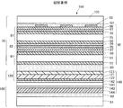
- FIG. 1 is a schematic configuration diagram of a stacked body according to the first embodiment.
- FIGS. 2A to 2C are views schematically showing the manufacturing process of the laminate according to the first embodiment.
- FIG. 3A to FIG. 3C are diagrams schematically showing a manufacturing process of the laminate according to the first embodiment.
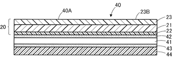
- FIG. 4 is a schematic configuration diagram of the polarizing plate according to the first embodiment.
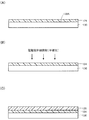
- FIGS. 5A to 5C are diagrams schematically showing a manufacturing process of the polarizing plate according to the first embodiment.
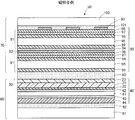
- FIG. 6 is a schematic configuration diagram of the image display apparatus according to the first embodiment.
- FIG. 7 is a schematic configuration diagram of a stacked body according to the second embodiment.
- FIG. 8C are diagrams schematically showing a manufacturing process of the laminated body according to the second embodiment.
- FIG. 9A to FIG. 9C are diagrams schematically showing a manufacturing process of the laminated body according to the second embodiment.
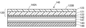
- FIG. 10 is a schematic configuration diagram of a polarizing plate according to the second embodiment.
- FIG. 11A to FIG. 11C are diagrams schematically showing a manufacturing process of the polarizing plate according to the first embodiment.
- FIG. 12 is a schematic configuration diagram of an image display apparatus according to the second embodiment.
- a protective film, a laminate, a polarizing plate, and an image display device will be described with reference to the drawings.
- terms such as “film” and “sheet” are not distinguished from each other only based on the difference in designation. Therefore, for example, “film” is used to include a member that is also called a sheet.
- “light transmittance” in the present specification means a property of transmitting light. For example, the total light transmittance is 50% or more, preferably 70% or more, more preferably 80% or more, particularly preferably. Including 90% or more.
- the light transmissive property does not necessarily need to be transparent, and may be translucent.
- FIGS. 2 (A) to 2 (C) and FIGS. 3 (A) to 3 (C) show the production of the protective film according to the present embodiment. It is the figure which showed the process typically.
- a laminate 10 shown in FIG. 1 includes a protective film 20 and a release film 30 laminated on the protective film 20.
- the protective film 20 is a protective film that does not include a base material, that is, does not have a base material.
- the “base material” in the present specification means a film or sheet made of a thermoplastic resin or glass serving as a support for forming a protective film.
- Examples of the base material include cellulose acylate base materials such as triacetyl cellulose, cycloolefin polymer base materials, polycarbonate base materials, acrylic base materials, polyester base materials such as polyethylene terephthalate base materials, and glass base materials.
- the release film 30 since the release film 30 is finally peeled from the protective film 20, it does not constitute a part of the protective film 20.
- the protective film 20 includes a core layer 21 and an adhesion improving layer 22 provided on one surface 21A of the core layer 21.
- the protective film 20 may further include a light transmissive functional layer 23 provided on the other surface 21 ⁇ / b> B of the core layer 21.
- the thickness of the protective film 20 is less than 40 ⁇ m from the viewpoint of reducing the thickness of the protective film 20.
- the thickness of the protective film 20 is obtained by taking a cross-section of the protective film 20 using a scanning electron microscope (SEM), measuring 20 thicknesses of the protective film 20 in the cross-sectional image, and averaging the thicknesses of the 20 locations. Value. From the viewpoint of reducing the thickness of the protective film 20, the thickness of the protective film 20 is preferably less than 21 ⁇ m, more preferably less than 15 ⁇ m, and most preferably less than 10 ⁇ m.
- the protective film 20 shown in FIG. 1 has a three-layer structure including a light-transmitting functional layer 23, a core layer 21, and an adhesion improving layer 22, but the interface between the layers does not necessarily have to be clear.
- the interface between each layer is not clear, it can be determined as a light-transmitting functional layer, a core layer, and an adhesion improving layer by analyzing the components of each layer.
- the tensile breaking strength of the protective film 20 is 30 N / mm 2 or more.
- the tensile breaking strength of the protective film 20 is measured according to JIS K7161-1: 2014 by using a Tensilon universal testing machine and pulling the protective film at a test speed of 300 mm / min with a width of 25 mm and a distance between chucks of 80 mm.
- the stress applied to the protective film when the protective film is broken is taken as the tensile strength at break.
- the tensile strength at break is the arithmetic average of the values obtained by measuring three times.
- the tensile breaking strength of the protective film 20 shall be measured in the state which peeled the release film 30.
- the tensile breaking strength of the protective film 20 is preferably 40 N / mm 2 or more.
- the moisture permeability of the protective film 20 is preferably 100 g / (m 2 ⁇ 24 h) or more and 600 g / (m 2 ⁇ 24 h) or less.
- moisture permeability of the protective film is less than 100 g / (m 2 ⁇ 24 h)
- moisture is difficult to escape from the protective film when an aqueous adhesive is applied, so that wrinkles are likely to occur
- an organic light emitting diode when an organic light emitting diode is used as a display element, the organic light emitting diode may be deteriorated by moisture.
- “moisture permeability” refers to a protective film measured in an atmosphere at a temperature of 40 ° C.
- the lower limit of the moisture permeability of the protective film 20 is more preferably 200 g / (m 2 ⁇ 24 h) or more, and the upper limit is more preferably 500 g / (m 2 ⁇ 24 h) or less.
- the protective film 20 preferably has a light transmittance of 7% or less at a wavelength of 380 nm.
- the upper limit of the transmittance of light with a wavelength of 380 nm of the protective film is more preferably 5%.
- the light transmittance can be measured using a spectrophotometer (product name “UV-2450”, manufactured by Shimadzu Corporation).
- the transmittance is an arithmetic average value obtained by measuring three times.
- the protective film 20 preferably has a haze value (total haze value) of less than 1%.
- a haze value total haze value
- the upper limit of the haze value of the protective film 20 is more preferably less than 0.5%, further preferably 0.4% or less, further preferably 0.3% or less, and 0.2% or less. Most preferably.
- the haze value is the haze value of the protective film 20 before the moisture and heat resistance test described later, but the haze value of the protective film 20 after the moisture and heat resistance test is also preferably less than 1%.
- the haze value of the protective film 20 after the wet heat resistance test is more preferably less than 0.5%, and most preferably 0.3% or less.
- the haze value can be determined using a haze meter (product name “HM-150”, manufactured by Murakami Color Research Laboratory) in accordance with JIS K7136: 2000.
- the haze value is the arithmetic average value of the values obtained by measuring three times.
- the light transmittance and haze value of the protective film 20 can be achieved, for example, by adjusting the addition amount of the ultraviolet absorber in the core layer 21 or the like.
- the protective film 20 may be cut into a desired size, but may be in a roll shape.
- the size of the protective film is not particularly limited, and examples thereof include smartphones, tablet terminals, personal computers (PCs), wearable terminals, digital signage, and televisions. It is determined appropriately according to the size of the display surface of the image display device. Specifically, the size of the protective film 20 may be, for example, 1 inch or more and 500 inches or less.
- the core layer 21 is a layer containing a resin made of a cured product.
- a resin made of a cured product is used as the resin for forming the core layer 21 when the core layer is formed using a solvent-drying resin such as a thermoplastic resin instead of this resin. This is because the layer becomes too soft and the pencil hardness of the protective film is lowered.
- the core layer 21 may be a layer made of only the above resin, but may contain an additive for exhibiting a desired function.
- the additive is not particularly limited, but mobile devices are often used outdoors, and the polarizer is exposed to ultraviolet rays and easily deteriorates. Therefore, it absorbs ultraviolet rays and suppresses deterioration of the polarizer due to ultraviolet rays. Ultraviolet absorbers (UVA) are preferred.
- the core layer 21 may contain inorganic particles such as silica particles, talc, organic fibers, or the like as additives in order to increase dimensional stability and breaking strength. As the organic fiber, cellulose nanofiber can be preferably used.
- the resin functions as a binder resin.
- the film thickness of the core layer 21 is preferably 5 ⁇ m or more and less than 40 ⁇ m. By making the film thickness of the core layer 21 in this range, it is possible to suppress a significant decrease in the strength of the core layer 21 and to form a curable composition for forming the core layer 21 (hereinafter, this composition is referred to as “core layer use”).
- the composition can be easily coated, and the workability (particularly chipping resistance) caused by the core layer 21 being too thick is not deteriorated.
- the film thickness of the core layer 21 can be determined by observing the cross section of the core layer with a scanning electron microscope (SEM).
- the film thickness of the three core layers 21 is measured in one image, this is performed for five images, and the average value of the measured film thickness is calculated.
- the upper limit of the film thickness of the core layer 21 is more preferably 30 ⁇ m or less, further preferably 20 ⁇ m or less, and most preferably 10 ⁇ m or less.
- the resin contained in the core layer 21 is a resin made of a cured product.
- a resin made of a cured product (polymer) of an ionizing radiation polymerizable compound is preferable.
- An ionizing radiation polymerizable compound is a compound having one or more ionizing radiation polymerizable functional groups capable of undergoing a polymerization reaction upon irradiation with ionizing radiation. Examples of the ionizing radiation polymerizable functional group include ethylenically unsaturated groups such as a (meth) acryloyl group, a vinyl group, and an allyl group.
- the “(meth) acryloyl group” means to include both “acryloyl group” and “methacryloyl group”.
- Examples of the ionizing radiation irradiated when polymerizing the ionizing radiation polymerizable compound include visible light, ultraviolet rays, X-rays, electron beams, ⁇ rays, ⁇ rays, and ⁇ rays.
- an ionizing radiation polymerizable oligomer or an ionizing radiation polymerizable prepolymer as the ionizing radiation polymerizable compound.
- the ionizing radiation polymerizable oligomer or ionizing radiation polymerizable prepolymer include urethane (meth) acrylate, polyester (meth) acrylate, epoxy (meth) acrylate, melamine (meth) acrylate, polyfluoroalkyl (meth) acrylate, silicone (meta ) Oligomer or prepolymer such as acrylate.
- ionizing radiation polymerizable oligomers or ionizing radiation polymerizable prepolymers may be used alone or in combination of two or more.
- the weight average molecular weight of the ionizing radiation polymerizable oligomer or ionizing radiation polymerizable prepolymer is preferably 1000 or more and 20000 or less.
- the “weight average molecular weight” is a value obtained by dissolving in a solvent such as tetrahydrofuran (THF) and converting to polystyrene by a conventionally known gel permeation chromatography (GPC) method.
- GPC gel permeation chromatography
- the lower limit of the weight average molecular weight of the ionizing radiation polymerizable oligomer or ionizing radiation polymerizable prepolymer is more preferably 3000 or more, the upper limit is more preferably 12000 or less, and even more preferably 10,000 or less.
- the resin may be a cured product of a mixture further containing a monofunctional ionizing radiation polymerizable monomer in addition to the ionizing radiation polymerizable oligomer or ionizing radiation polymerizable prepolymer for adjusting the hardness and viscosity of the composition. .
- the monofunctional ionizing radiation polymerizable monomer is a compound having one or more ionizing radiation polymerizable functional groups in the molecule.
- Examples of the monofunctional ionizing radiation polymerizable monomer include hydroxyethyl acrylate (HEA), glycidyl methacrylate, methoxypolyethylene glycol (meth) acrylate, isostearyl (meth) acrylate, 2-acryloyloxyethyl succinate, and the like.
- the ultraviolet absorber has a function of absorbing ultraviolet rays. Although it does not specifically limit as an ultraviolet absorber, For example, a triazine type ultraviolet absorber, a benzophenone type ultraviolet absorber, a benzotriazole type ultraviolet absorber, etc. are mentioned.
- Examples of the triazine ultraviolet absorber include 2- (2-hydroxy-4- [1-octyloxycarbonylethoxy] phenyl) -4,6-bis (4-phenylphenyl) -1,3,5-triazine.
- triazine-based ultraviolet absorbers examples include TINUVIN460 (manufactured by BASF Japan), LA-46 (manufactured by ADEKA), and the like.
- benzophenone ultraviolet absorber examples include 2-hydroxybenzophenone, 2,4-dihydroxybenzophenone, 2,2′-dihydroxy-4,4′-dimethoxybenzophenone, 2,2 ′, 4,4′-tetrahydroxy. Examples thereof include benzophenone, 2-hydroxy-4-methoxybenzophenone, hydroxymethoxybenzophenone sulfonic acid and its trihydrate, hydroxymethoxybenzophenone sulfonate sodium, and the like. Moreover, as a commercially available benzophenone type ultraviolet absorber, CHMASSORB81 / FL (made by BASF Japan) etc. are mentioned, for example.
- benzotriazole ultraviolet absorber examples include 2-ethylhexyl-3- [3-tert-butyl-4-hydroxy-5- (5-chloro-2H-benzotriazol-2-yl) phenyl] propionate, 2 -(2H-benzotriazol-2-yl) -6- (linear and side chain dodecyl) -4-methylphenol, 2- [5-chloro (2H) -benzotriazol-2-yl] -4-methyl- 6- (tert-butyl) phenol, 2- (2H-benzotriazol-2-yl) -4,6-di-tert-pentylphenol, 2- (2′-hydroxy-5′-methylphenyl) benzotriazole, 2- (2′-hydroxy-3 ′, 5′-di-tert-butylphenyl) benzotriazole, 2- (2′-hydroxy-3) -Tert-butyl-5'-methylphenyl) benzotriazole, 2- (2'-
- benzotriazole ultraviolet absorbers examples include KEMISORB 71D, KEMISORB 79 (all manufactured by Chemipro Kasei Co., Ltd.), JF-80, JAST-500 (all manufactured by Johoku Chemical Co., Ltd.), ULS-1933D. (Manufactured by one company), RUVA-93 (manufactured by Otsuka Chemical Co., Ltd.) and the like.
- triazine-based ultraviolet absorbers are preferably used.
- the ultraviolet absorber is dissolved in the ionizing radiation polymerizable monomer or ionizing radiation polymerizable oligomer constituting the core layer 21.
- TINUVIN400 manufactured by BASF Japan
- BASF Japan is particularly preferably used.
- the content of the ultraviolet absorber is not particularly limited, but is preferably 1 part by mass or more and 6 parts by mass or less with respect to 100 parts by mass of the resin solid content of the core layer composition.
- the ultraviolet absorber in the composition for the core layer is within this range, the ultraviolet absorber can be sufficiently contained in the core layer, and it is possible to suppress the occurrence of significant coloring and strength reduction in the core layer.
- the minimum with more preferable content of a ultraviolet absorber is 2 mass parts or more, and a more preferable upper limit is 5 mass parts or less.
- the core layer 21 may contain a leveling agent.
- the core layer 21 may have other components such as a lubricant, a plasticizer, a filler, a filler, an antistatic agent, an antiblocking agent, a crosslinking agent, a light stabilizer, a colorant such as a dye, and a pigment as necessary. May be contained.
- the leveling agent means an additive that prevents defects such as repellency, dents, pinholes, and scums caused by uneven surface tension of the core layer and smoothes the surface.
- a leveling agent is not specifically limited, The compound etc. which have a polyether group, a polyurethane group, an epoxy group, a carboxyl group, an acrylate group, a methacrylate group, a carbinol group, or a hydroxyl group are mentioned.
- the leveling agent may have a polyether group, a polyurethane group, an epoxy group, a carboxyl group, an acrylate group, a methacrylate group, a carbinol group, or a hydroxyl group at the end of the main chain (one end or both ends). You may have in a chain
- the leveling agent is not particularly limited as long as it is a compound having a polyether group, a polyurethane group, an epoxy group, a carboxyl group, an acrylate group, a methacrylate group, a carbinol group, or a hydroxyl group. / Fluorine mixed, acrylic, methacrylic and aromatic leveling agents.
- a leveling agent containing a silicon atom is likely to have poor recoatability when added in a large amount, and coating defects such as repelling may increase. Therefore, a fluorine-based leveling agent is preferred as the leveling agent.
- fluorine leveling agents include F-568, F-556, F-554, and F-553 (all manufactured by DIC).
- the content of the leveling agent is preferably 0.01 parts by mass or more and 5 parts by mass or less with respect to 100 parts by mass of the resin solid content in the core layer composition. By setting the content of the leveling agent within this range, it is possible to obtain the core layer 21 with more excellent flatness.
- the adhesion improving layer 22 is a layer for improving adhesion with an adhesive.
- the “adhesion improving layer” means a layer having a peel strength of 1 N or more when the peel strength at the interface with the adhesive is measured by the following method. Specifically, first, when a substrate-less protective film is not incorporated in the polarizing plate, a polyvinyl alcohol-based adhesive (polyvinyl alcohol resin (product name “PVA-117”, manufactured by Kuraray Co., Ltd.)) is purified water.
- the material is pasted and a substrate-less protective film is incorporated into the polarizing plate.
- the surface of the polarizing plate on the substrate-less protective film side is pasted to the glass plate with a double-sided tape “751B” manufactured by Teraoka Seisakusho so that the polarizing plate protrudes from the glass plate.
- the polarizing plate protruding from the glass plate is gripped by a chuck, and a tensile test is performed at an angle of 180 degrees at a speed of 375 mm / min.
- the layer in contact with the adhesive at that time and the adhesive in the baseless protective film The peel strength at the interface is measured.
- the strength obtained by averaging the stroke amount (pull length) between 100 mm and 200 mm is defined as the peel strength.
- the surface of the base material-less protective film side of the polarizing plate is used with a double-sided tape “751B” manufactured by Teraoka Seisakusho.
- the glass plate is pasted so that the polarizing plate protrudes from the glass plate. Then, the peel strength is measured in the same procedure as described above.
- the peel strength at the interface between the adhesive and the core layer is 100 mN or less, so the adhesive is in contact with the adhesive on the core layer.
- the peel strength between the adhesive and this layer is 1 N or more, it can be determined that the adhesion with the adhesive is improved by this layer. It can be said that.
- the adhesion improving layer 22 is not particularly limited as long as it can improve the adhesion with the adhesive.
- the core layer 21 includes an ultraviolet absorber
- the adhesion improving layer 22 is formed on the surface of the core layer 21. Since the ultraviolet absorber may precipitate (bleed out) and the haze value of the protective film may increase, the adhesion improving layer 22 suppresses the precipitation of the ultraviolet absorber in addition to the function of improving the adhesiveness. The function to perform may be demonstrated.
- the contact angle of the surface 22A of the adhesion improving layer 22 after saponification treatment with water is 80 ° or less.
- the saponification treatment is performed by immersing the protective film or laminate in a 2N sodium hydroxide aqueous solution at a temperature of 55 ° C. for 3 minutes.
- the contact angle with respect to water on the surface 22A of the adhesion improving layer 22 is determined by a microscopic contact angle meter (product name “CA-QI series”, manufactured by Kyowa Interface Science Co., Ltd.) in accordance with the sessile drop method described in JIS R3257-1999. Can be used to measure.
- the contact angle with respect to water of the surface 22A of the adhesion improving layer 22 is more preferably 70 ° or less.
- the adhesion improving layer 22 may have a function of suppressing the precipitation of the ultraviolet absorber in addition to the function of improving the adhesiveness with the adhesive.
- whether or not it has a function of suppressing the precipitation of the ultraviolet absorber is determined by performing a moisture and heat resistance test in which the optical film is allowed to stand in an environment of 80 ° C. and 90% relative humidity for 24 hours. Whether the ratio of the haze value of the protective film after the wet heat resistance test to the haze value of the previous protective film is 10 or less can be determined.
- the adhesion improving layer if the ratio of the haze value of the protective film after the moist heat resistance test to the haze value of the protective film before the moist heat resistance test is 10 or less, the adhesion It is determined that the improvement layer also has a function of suppressing the precipitation of the ultraviolet absorber.
- the haze value can be determined using a haze meter (product name “HM-150”, manufactured by Murakami Color Research Laboratory) in accordance with JIS K7136: 2000.
- the haze value is the arithmetic average value of the values obtained by measuring three times.
- the ratio of the haze value of the protective film 20 after the wet heat resistance test to the haze value of the protective film 20 before the wet heat resistance test is preferably 5 or less, and more preferably 3 or less.
- the film thickness of the adhesion improving layer 22 is preferably 100 nm or more and less than 800 nm. If the film thickness of the adhesion improving layer is less than 100 nm, the adhesion with the adhesive may not be improved, and if the film thickness of the adhesion improving layer is 800 nm or more, curing shrinkage increases, and the core layer There is a possibility that the adhesiveness with will deteriorate.
- the film thickness of the adhesion improving layer 22 can be measured by the same measuring method as the measuring method of the film thickness of the core layer 21.
- the lower limit of the film thickness of the adhesion improving layer 22 is more preferably 150 nm or more.
- the upper limit of the film thickness of the adhesion improving layer 22 is more preferably 600 nm or less, and most preferably 500 nm or less.
- the adhesive improvement layer 22 is a curable composition (hereinafter referred to as “ionizing radiation polymerizable compound”) and a silane coupling agent having a reactive functional group and a hydrolyzable group from the viewpoint of improving the adhesiveness with the adhesive.
- the composition is preferably referred to as a “adhesion improving layer composition”).
- the ionizing radiation polymerizable compound in the composition for improving adhesiveness may be a compound having one or more ionizing radiation polymerizable functional groups in the molecule, but many compounds having two or more ionizing radiation polymerizable functional groups in the molecule. It is preferably a functional ionizing radiation polymerizable compound.
- the scratch resistance of the adhesion improving layer 22 can be improved, and the adhesiveness with the core layer 21 can be further ensured.
- an ultraviolet absorber when an ultraviolet absorber is added to the core layer, the ultraviolet absorber tends to move from the core layer to the adhesion improving layer and precipitate on the surface of the adhesion improving layer.
- the polyfunctional ionizing radiation polymerizable compound preferably has 2 or more ionizing radiation polymerizable functional groups in the molecule, and more preferably 3 or more.
- the ionizing radiation polymerizable compound in the composition for improving adhesiveness is not particularly limited, but is an ester compound of polyhydric alcohol and (meth) acrylic acid, heterocyclic (meth) acrylate, urethane (meth) acrylate, polyester. (Meth) acrylate, epoxy (meth) acrylate, and a mixture thereof may be mentioned.
- a silane coupling agent is an organosilicon compound having a reactive functional group and a hydrolyzable group.
- the reactive functional group is a group capable of reacting with a polyfunctional ionizing radiation polymerizable compound or the like, and the reactive functional group includes a vinyl group, an epoxy group, a styryl group, a (meth) acryloyl group, an amino group, a ureido group,
- One or more functional groups selected from the group consisting of a thiol group, a sulfide group and an isocyanate group can be mentioned.
- a (meth) acryloyl group is preferable from the viewpoint of adhesion with the core layer 21.
- the hydrolyzable group is a group capable of generating a silanol group (Si—OH) and an alcohol by hydrolysis.
- examples of the hydrolyzable group include a halogen atom, an alkoxy group, an acyloxy group, an alkenyloxy group, Examples thereof include a carbamoyl group, an amino group, an aminooxy group, and a ketoximate group.
- the hydrolyzable group has a carbon atom, the number of carbon atoms is preferably 6 or less, and more preferably 4 or less.
- an alkoxy group or an alkenyloxy group having 4 or less carbon atoms is preferable, and a methoxy group or an ethoxy group is particularly preferable.
- silane coupling agent examples include, for example, 3-methacryloyloxypropylmethyldimethoxysilane, 3-methacryloyloxypropyltrimethoxysilane, 3-methacryloyloxypropylmethyldiethoxysilane, 3-methacryloyloxypropyltriethoxysilane, 3 -Acryloyloxypropyltriethoxysilane and the like.
- content of a silane coupling agent is 10 to 50 mass parts with respect to 100 mass parts of resin solid content in the composition for adhesive improvement layers. By making content of a silane coupling agent into this range, adhesiveness with an adhesive agent can be made more favorable.
- the “light-transmitting functional layer” in the present specification is a layer having a light-transmitting property and intended to exhibit some function in the protective film.
- examples of the light-transmitting functional layer include a layer for exhibiting a function such as hard coat property or antireflection property.
- the light transmissive functional layer may be not only a single layer but also a laminate of two or more layers. When two or more light-transmitting functional layers are laminated, the functions of each layer may be the same or different. In the present embodiment, a case where the light transmissive functional layer 23 is a layer having hard coat properties, that is, a hard coat layer will be described.
- the light-transmitting functional layer 23 functions as a hard coat layer as described above, the light-transmitting functional layer 23 has a hardness of “H” or higher in the pencil hardness test specified by JIS K5600-5-4: 1999. It is the layer which has.
- the pencil hardness test is performed in a state where a load of 750 g is applied to the pencil and the scratching speed is 1 mm / second.
- the pencil hardness is the highest hardness at which the surface of the light-transmitting functional layer was not damaged in the pencil hardness test.
- the pencil hardness is measured using a plurality of pencils having different hardnesses.
- the pencil hardness test is performed five times for each pencil, and the surface of the optical film is scratched four times or more out of the five times. If not, it is determined that the surface of the light-transmitting functional layer was not damaged in the pencil having this hardness.
- the above-mentioned scratches refer to those that are visually observed through transmission observation of the surface of the light-transmitting functional layer subjected to the pencil hardness test under a fluorescent lamp.
- the upper limit of the pencil hardness of the light-transmitting functional layer 23 is preferably about 4H.
- the surface 23B opposite to the surface 23A on the core layer 21 side in the light transmissive functional layer 23 (hereinafter, this surface is referred to as “the surface of the light transmissive functional layer”) is the other surface 20B of the protective film 20. I am doing.
- the arithmetic average roughness (Ra) is 0.5 nm or more and 1.5 nm or less, respectively.
- the maximum height (Rz) is preferably 4 nm or more and 20 nm or less, and the maximum peak height (Rp) is preferably 2 nm or more and 15 nm or less.
- the definitions of Ra, Rz and Rp shall conform to JIS B0601: 2001.
- Ra, Rz, and Rp are calculated as follows using, for example, an atomic force microscope (product name “WET-9100”, manufactured by Shimadzu Corporation). Specifically, first, at least three locations that are not visually abnormal (locations where there are no large foreign objects or scratches) are randomly selected in the protective film and cut into 5 mm squares to obtain three samples.
- a plurality of flat circular metal plates having a diameter of 15 mm and a thickness of 1 mm are prepared, and a carbon double-sided tape manufactured by Nissin EM Co., Ltd. is attached to each metal plate.
- a carbon double-sided tape manufactured by Nissin EM Co., Ltd. is attached to each metal plate.
- One sample is stuck on the tape so that the surface of the sample (the surface of the protective film) is on the upper side.
- the sample-attached metal plate is left overnight in a desiccator.
- the metal plate with the sample is fixed with a magnet on the measurement table of the atomic force microscope (product name “WET-9400”, manufactured by Shimadzu Corporation), and in the tapping mode, the measurement area is 1 ⁇ m square and 5 ⁇ m square.
- the surface shape is observed with an atomic force microscope.
- Ra, Rz, and Rp are calculated from the observed data using surface analysis software built in the atomic force microscope.
- the vertical scale during the surface analysis is 20 nm.
- Observation is performed at room temperature, and NCHR-20 manufactured by NanoWorld is used as a cantilever. For observation, five locations are selected at random for one sample, and the surface shape is observed for 3 samples ⁇ 5 locations (total of 15 points).
- Ra, Rz, Rp are calculated using the surface analysis software built in the atomic force microscope, and the arithmetic average values of the 15 points are calculated as Ra, Rz, Rp for each sample.
- the reason why Ra and the like on the surface 23B of the light transmissive functional layer 23 are measured in the 1 ⁇ m square region is to increase the resolution compared to the measurement in the 5 ⁇ m square region.
- the reason for measuring Ra and the like on the surface 23B in the 5 ⁇ m square region is to observe the surface shape in a wider region than in the 1 ⁇ m square region.
- Ra is used to see the average value of the heights of the peaks and valleys existing on the surface of the light-transmitting functional layer
- Rz is the maximum peak height and the valley depth of the surface of the light-transmitting functional layer
- Rp is used to see the maximum peak height of the surface of the light-transmitting functional layer.
- Ra is looking at the average value of the heights of the peaks and valleys present on the surface of the light-transmitting functional layer, although the rough surface shape of the light-transmitting functional layer can be understood, there are large peaks and valleys. If so, it will be averaged out and may overlook its existence.
- Rp looks at the maximum peak height on the surface of the light-transmitting functional layer, when two parameters Ra and Rp are used, even if there is a large valley, the existence is overlooked.
- Rz is the sum of the maximum peak height and the maximum valley depth on the surface of the light-transmitting functional layer, when two parameters Ra and Rz are used, May not know whether the mountain is high or the valley is deep. Therefore, in order to more accurately determine whether or not the surface has a uniform and flat surface shape, one parameter of Ra, two parameters of Ra and Rp, or two parameters of Ra and Rz are not sufficient. , Rz and Rp are required. For this reason, in the present embodiment, the surface shape of the light transmissive functional layer is defined using three parameters Ra, Rz, and Rp.
- Ra in the 1 ⁇ m square and 5 ⁇ m square regions on the surface of the light-transmitting functional layer is less than 0.5 nm, the protective films are adhered to each other when the protective film is wound in a roll shape due to being too smooth. If Ra exceeds 1.5 nm, the contact angle with water increases, and the haze value increases due to surface irregularities, which may impair transparency. Therefore, as described above, Ra in the 1 ⁇ m square and 5 ⁇ m square regions of the surface 23B of the light-transmitting functional layer 23 is preferably 0.5 nm or more and 1.5 nm or less, respectively.
- the lower limit of Ra is preferably 1.0 nm or more.
- Rz in the 1 ⁇ m square and 5 ⁇ m square regions of the surface of the light-transmitting functional layer is less than 4 nm, the protective films may be adhered to each other when the protective film is wound into a roll due to being too smooth.
- Rz exceeds 20 nm the contact angle with water increases, and the haze value increases due to surface irregularities, which may impair transparency.
- Rz in the 1 ⁇ m square and 5 ⁇ m square regions of the surface 23B of the light-transmitting functional layer 23 is preferably 4 nm or more and 20 nm or less, respectively.
- the lower limit of Rz is preferably 5 nm or more, and the upper limit of Rz is 15 nm or less. preferable.
- Rp in the 1 ⁇ m square and 5 ⁇ m square regions of the surface of the light-transmitting functional layer is less than 2 nm, the protective films may be adhered to each other when the protective film is wound into a roll due to being too smooth.
- Rp exceeds 15 nm the contact angle with water increases, and the haze value increases due to surface irregularities, which may impair transparency.
- Rp in the 1 ⁇ m square and 5 ⁇ m square regions of the surface 23B of the light-transmitting functional layer 23 is preferably 2.0 nm or more and 15 nm or less, respectively.
- the lower limit of Rp is preferably 3 nm or more, and the upper limit of Rp is 10 nm or less, respectively. preferable.
- Arithmetic mean roughness (Ra) in the area of 1 ⁇ m square and 5 ⁇ m square of surface 23B is 0.5 nm to 1.5 nm, maximum height (Rz) is 4 nm to 20 nm, and maximum peak height
- the light transmissive functional layer 23 having (Rp) of 2 nm or more and 15 nm or less can be realized by transferring the surface shape of the release film 30 to the surface 23B of the light transmissive functional layer 23.
- the surface shape of the release film 30 is transferred to the surface 23B of the light transmissive functional layer 23 to obtain the specific surface shape, the production is not affected by the additive contained in the light transmissive functional layer 23. It becomes easy.
- a specific function of the light transmissive functional layer 23 as in this embodiment may be used depending on a conventional manufacturing method such as a method of applying and curing a composition for a light transmissive functional layer on a light transmissive substrate. It is extremely difficult to form a surface shape.
- the film thickness of the light transmissive functional layer 23 is preferably 2.0 ⁇ m or more and 15 ⁇ m or less. If the film thickness of the light-transmitting functional layer 23 is within this range, desired hardness can be obtained, residual solvent can be reduced, and deterioration in adhesion can be suppressed.
- the film thickness of the light transmissive functional layer 23 can be measured by a method similar to the method for measuring the film thickness of the core layer 21.
- the lower limit of the film thickness of the light transmissive functional layer 23 is more preferably less than 12 ⁇ m from the viewpoint of suppressing cracking of the light transmissive functional layer. Moreover, from the viewpoint of suppressing curling while reducing the thickness of the light transmissive functional layer, the thickness of the light transmissive functional layer 23 is more preferably 3 ⁇ m or more and less than 10 ⁇ m.
- the refractive index of the light transmissive functional layer 23 may be 1.50 or more and 1.60 or less.
- the lower limit of the refractive index of the light transmissive functional layer 23 may be 1.52 or more, and the upper limit of the refractive index of the light transmissive functional layer 23 may be 1.56 or less.
- the refractive index of the light-transmitting functional layer 23 can be measured with an Abbe refractometer (product name “NAR-4T”, manufactured by Atago Co., Ltd.) or an ellipsometer. Further, the light transmissive functional layer 23 is scraped off with a cutter or the like to prepare a powder sample, and the Becke method (refractive index is in accordance with B method (for powder or granular transparent material) described in JIS K7142: 2008). Using a known Cargill reagent, place the powdered sample on a slide glass, etc., drop the reagent onto the sample, and immerse the sample in the reagent.
- the refractive index of the light-transmitting functional layer 23 may be obtained by a method in which the refractive index of the reagent in which the bright line (Becke line) generated in the contour of the sample cannot be visually observed due to the difference in the refractive index of the sample is used. .
- the light-transmitting functional layer 23 preferably contains a resin made of a cured product (polymer) of an ionizing radiation polymerizable compound.
- the light transmissive functional layer 23 may be a layer made only of a resin, but it is preferable that the light transmissive functional layer 23 contains inorganic particles in addition to the resin from the viewpoint of improving the hardness of the light transmissive functional layer.
- the resin functions as a binder resin.
- the light transmissive functional layer 23 may contain a leveling agent.
- the resin contained in the light-transmitting functional layer 23 is preferably made of a cured product of an ionizing radiation polymerizable compound.
- the ionizing radiation polymerizable compound include an ionizing radiation polymerizable monomer and an ionizing radiation polymerizable oligomer. Or ionizing radiation-polymerizable prepolymers, which can be appropriately adjusted and used.
- the ionizing radiation polymerizable compound a combination of an ionizing radiation polymerizable monomer and an ionizing radiation polymerizable oligomer or an ionizing radiation polymerizable prepolymer is preferable.
- ionizing radiation polymerizable monomer As the ionizing radiation polymerizable monomer, a polyfunctional monomer having two or more ionizing radiation polymerizable functional groups (that is, bifunctional) is preferable.
- the ionizing radiation polymerizable monomer include an ionizing radiation polymerizable monomer into which a modifying group such as alkylene oxide modification, urethane modification, epoxy modification, or alkoxy modification is introduced.
- alkylene oxide-modified (meth) acrylate is preferable from the viewpoint of obtaining a protective film having good peelability from a release film, tackiness, and high mechanical strength.
- alkylene oxide include methylene oxide, ethylene oxide, propylene oxide, butylene oxide and the like.
- ethylene oxide-modified (EO-modified) acrylate and propylene oxide-modified (PO-modified) acrylate are more preferable from the viewpoint of obtaining good peelability and scratch resistance. Further, among these, PO-modified acrylate is particularly preferable because it has a good balance between peelability and scratch resistance.
- ionizing radiation polymerizable oligomer examples include urethane (meth) acrylate, polyester (meth) acrylate, epoxy (meth) acrylate, melamine (meth) acrylate, polyfluoroalkyl (meth) acrylate, silicone (meth) acrylate and the like. Can be mentioned.
- the ionizing radiation polymerizable prepolymer is preferably from 10,000 to 80,000, more preferably from 10,000 to 40,000. When the weight average molecular weight exceeds 80,000, the viscosity is high, so that the coating suitability is lowered, and the appearance of the resulting protective film may be deteriorated.
- ionizing radiation polymerizable prepolymers include urethane (meth) acrylate, polyester (meth) acrylate, epoxy (meth) acrylate, melamine (meth) acrylate, polyfluoroalkyl (meth) acrylate, and silicone (meth) acrylate. Etc. Among these, urethane acrylate prepolymers are preferable from the viewpoint of improving interlayer adhesion with the core layer.
- the ionizing radiation polymerizable monomer is an EO-modified acrylate
- the ionizing radiation polymerizable prepolymer is a urethane acrylate prepolymer.
- the ionizing radiation polymerizable monomer and the ionizing radiation polymerizable prepolymer are preferably contained at 90:10 to 70:30. By containing the ionizing radiation polymerizable monomer and the ionizing radiation polymerizable prepolymer within this range, flexibility and toughness can be improved without lowering the hardness.
- the inorganic particles are components for improving the mechanical strength and pencil strength of the light-transmitting functional layer 23.
- the inorganic particles include silica (SiO 2 ) particles, alumina particles, titania particles, tin oxide particles, Inorganic oxide particles such as antimony-doped tin oxide (abbreviation: ATO) particles and zinc oxide particles can be given.
- silica particles are preferable from the viewpoint of further increasing the hardness, and among the silica particles, irregular-shaped silica particles are more preferable.
- the deformed silica particles can achieve the same hardness as that of spherical silica particles, even if they are not as small as the commercially available spherical silica particles having the smallest particle diameter.
- the average primary particle diameter of the irregular shaped silica particles is preferably 1 nm or more and 100 nm or less. Even if the average primary particle diameter of the irregular shaped silica particles is within this range, the hardness equivalent to that of spherical silica having an average primary particle diameter of 1 nm or more and 45 nm or less can be achieved.
- the average particle diameter of the irregular-shaped silica particles was obtained by randomly extracting 10 irregular-shaped silica particles on a screen obtained by imaging the cross section of the light-transmitting functional layer with a transmission electron microscope (TEM) at a magnification of 200,000. After calculating the particle diameter, the average value is defined as the average particle diameter.
- the particle diameter of each irregular-shaped silica particle is an average value of the longest diameter and the shortest diameter in the cross section of the particle.
- the content of inorganic particles in the light transmissive functional layer 23 is preferably 20% by mass or more and 70% by mass or less.
- the content of the inorganic particles is less than 20% by mass, it becomes difficult to ensure sufficient hardness, and when the content of the inorganic particles exceeds 70% by mass, the filling rate increases too much, and the inorganic particles Adhesiveness with the resin component is deteriorated, and rather the hardness of the light-transmitting functional layer is lowered.
- inorganic particles it is preferable to use inorganic particles having reactive functional groups on the surface (reactive inorganic particles).
- Such inorganic particles having a reactive functional group on the surface can be prepared by surface-treating the inorganic particles with a silane coupling agent or the like.
- a method of treating the surface of the inorganic particles with a silane coupling agent a dry method in which the silane coupling agent is sprayed on the inorganic particles, or a wet method in which the inorganic particles are dispersed in a solvent and then the silane coupling agent is added and reacted. Etc.
- Leveling agent> Since the leveling agent contained in the light-transmitting functional layer 23 is the same as the leveling agent described in the column of the core layer 21, description thereof will be omitted here.
- the content of the leveling agent is based on 100 parts by mass of the resin solid content in the curable composition for forming the light transmissive functional layer 23 (hereinafter, this composition is referred to as “functional layer composition”).
- the content is preferably 0.01 parts by mass or more and 5 parts by mass or less.
- the release film 30 is for peeling the protective film 20 from the protective film 20 to transfer the protective film 20 to a polarizing plate described later.
- the release film 30 may be light transmissive. However, since the release film 30 is peeled after the protective film 20 is transferred to the polarizing plate, it may not be light transmissive.
- the thickness of the release film 30 is not particularly limited, but is preferably 25 ⁇ m or more and 100 ⁇ m or less. When the thickness of the release film is less than 25 ⁇ m, the effect of curing shrinkage of the light-transmitting functional layer becomes noticeable when the light-transmitting functional layer, which will be described later, is cured by ionizing radiation. If the thickness of the release film exceeds 100 ⁇ m, the production cost increases.
- the arithmetic average roughness (Ra) is 0.5 nm or more and 1.5 nm or less, respectively, and the maximum height (Rz) Is 4 nm or more and 20 nm or less, and when obtaining the light-transmitting functional layer 23 having a maximum peak height (Rp) of 2 nm or more and 15 nm or less, one surface 30A of the release film 30 is 1 ⁇ m square And 5 ⁇ m square, the arithmetic average roughness (Ra) is 0.5 nm to 1.5 nm, the maximum height (Rz) is 4 nm to 20 nm, and the maximum valley depth (Rv ) Are preferably 2 nm or more and 15 nm or less.
- Ra, Rz and Rv shall conform to JIS B0601: 2001.
- Ra, Rz, and Rv are the same procedures as Ra, Rz, and Rp described in the column of the light-transmitting functional layer 23 using, for example, an atomic force microscope (product name “WET-9100”, manufactured by Shimadzu Corporation). And calculated according to the conditions.
- the release film 30 is not particularly limited.
- a polyethylene terephthalate (PET) film having at least one surface untreated is preferably used.
- the untreated surface of the polyethylene terephthalate film is used as the release surface.
- a polyethylene terephthalate film having at least one surface untreated is excellent in releasability from the light-transmitting functional layer and is inexpensive, so that the production cost of the laminate of this embodiment can be kept low.
- the release film coated with a Si-based release agent containing a silicon atom is used as the release film, the release film has good peelability while having a light-transmitting function.
- the release agent component is transferred to the light-transmitting functional layer, resulting in an increase in the surface irregularity of the light-transmitting functional layer and an increase in the contact angle with water on the surface of the light-transmitting functional layer. May end up.
- a polyethylene terephthalate film having at least one surface untreated is used as the release film 30, there is no component transferred to the light transmissive functional layer 23 when the protective film 20 is transferred. The unevenness of the surface is small, and the contact angle of water hardly changes on the surface 23B of the light-transmitting functional layer 23 after transfer.
- the “polyethylene terephthalate film having at least one surface not treated” means a polyethylene terephthalate film having a surface that has not been surface-treated. Therefore, at least one side of the untreated polyethylene terephthalate film has no release agent for improving the peelability on the untreated side.
- the laminated body 10 and the protective film 20 can be produced as follows, for example. First, the light transmissive functional layer composition is applied to one surface 30A of the release film 30 and dried, and as shown in FIG. 2A, the light transmissive functional layer composition coating film 24 is applied. Form.
- the composition for a light-transmitting functional layer contains an ionizing radiation polymerizable compound, but in addition, the inorganic particles, the leveling agent, a solvent, and a polymerization initiator may be added as necessary. Furthermore, the composition for a light-transmitting functional layer includes a conventionally known dispersant, surface active agent, depending on purposes such as increasing the hardness of the light-transmitting functional layer, suppressing curing shrinkage, or controlling the refractive index. Agent, silane coupling agent, thickener, coloring agent, coloring agent (pigment, dye), antifoaming agent, flame retardant, UV absorber, adhesion promoter, polymerization inhibitor, antioxidant, surface modifier Further, an easy lubricant or the like may be added.
- solvent examples include alcohols (methanol, ethanol, propanol, isopropanol, n-butanol, s-butanol, t-butanol, benzyl alcohol, PGME, ethylene glycol, etc.), ketones (acetone, methyl ethyl ketone (MEK), cyclohexanone, etc.
- alcohols methanol, ethanol, propanol, isopropanol, n-butanol, s-butanol, t-butanol, benzyl alcohol, PGME, ethylene glycol, etc.
- ketones acetone, methyl ethyl ketone (MEK), cyclohexanone, etc.
- the polymerization initiator is a component that is decomposed by light or heat to generate radicals to initiate or advance polymerization (crosslinking) of the curable resin precursor.
- Examples of the polymerization initiator used in the composition for a light transmissive functional layer include a photopolymerization initiator (for example, a photo radical polymerization initiator, a photo cation polymerization initiator, and a photo anion polymerization initiator).
- photo radical polymerization initiator examples include benzophenone compounds, acetophenone compounds, acylphosphine oxide compounds, titanocene compounds, oxime ester compounds, benzoin ether compounds, thioxanthones, and the like.
- photo radical polymerization initiators examples include IRGACURE 184, IRGACURE 369, IRGACURE 379, IRGACURE 651, IRGACURE 819, IRGACURE 907, IRGACURE 2959, IRGACURE OXE01, Lucirin TPO 9 (all manufactured by BASF Japan 30) ADEKA), SPEEDCURE EMK (Nihon Sebel Hegner), benzoin methyl ether, benzoin ethyl ether, benzoin isopropyl ether (all manufactured by Tokyo Chemical Industry Co., Ltd.) and the like.
- photocationic polymerization initiator examples include aromatic diazonium salts, aromatic iodonium salts, aromatic sulfonium salts, and the like.
- examples of commercially available photocationic polymerization initiators include Adekaoptomer SP-150 and Adekaoptomer SP-170 (both manufactured by ADEKA).
- the content of the polymerization initiator in the composition for a light transmissive functional layer is preferably 0.5 parts by mass or more and 10.0 parts by mass or less with respect to 100 parts by mass of the ionizing radiation polymerizable compound.
- Examples of the method for applying the light transmissive functional layer composition include known coating methods such as spin coating, dipping, spraying, slide coating, bar coating, roll coating, gravure coating, and die coating. It is done.
- the coating film 24 is irradiated with ionizing radiation such as ultraviolet rays to polymerize (crosslink) the ionizing radiation polymerizable compound, thereby semi-curing the coating film 24 (half cure).
- ionizing radiation such as ultraviolet rays to polymerize (crosslink) the ionizing radiation polymerizable compound, thereby semi-curing the coating film 24 (half cure).
- ionizing radiation such as ultraviolet rays
- ultraviolet rays are used as the ionizing radiation for semi-curing the coating film 24 of the light transmissive functional layer composition, emit from an ultra-high pressure mercury lamp, high pressure mercury lamp, low pressure mercury lamp, carbon arc, xenon arc, metal halide lamp, etc. UV light and the like can be used. Further, as the wavelength of ultraviolet rays, a wavelength range of 190 to 380 nm can be used.
- the electron beam source include various electron beam accelerators such as a cockcroft-wald type, a bandegraft type, a resonant transformer type, an insulated core transformer type, a linear type, a dynamitron type, and a high frequency type.
- the core layer composition is applied to the surface of the coating film 24 opposite to the surface on the release film 30 side and dried. Then, a coating film 25 of the core layer composition is formed.
- the composition for the core layer contains the ionizing radiation polymerizable compound as described above.
- the ultraviolet absorber, the leveling agent, a solvent, and a polymerization initiator may be added as necessary. Since the solvent and polymerization initiator contained in the core layer composition are the same as the solvent and polymerization initiator described in the column for the light-transmitting functional layer composition, the description thereof will be omitted here.
- the coating film 25 is irradiated with ionizing radiation such as ultraviolet rays, so that the coating film 25 is semi-cured.
- ionizing radiation such as ultraviolet rays
- the composition for the adhesion improving layer is applied to the surface of the coating film 25 opposite to the coating film 24 side and dried.
- the coating film 26 of the composition for adhesion improving layer is formed.
- the composition for adhesive improvement layers contains a polyfunctional ionizing radiation polymerizable compound and a silane coupling agent as described above, a solvent and a polymerization initiator may be added as necessary. Since the solvent and polymerization initiator to be included in the composition for improving adhesiveness are the same as the solvent and polymerization initiator described in the column for the composition for light-transmitting functional layer, the description thereof will be omitted here. .
- the coating films 24 to 26 are irradiated with ionizing radiation such as ultraviolet rays to completely cure (full cure) the coating films 24 to 26.
- ionizing radiation such as ultraviolet rays to completely cure (full cure) the coating films 24 to 26.
- the light transmissive functional layer 23, the core layer 21, and the adhesive improvement layer 22 are formed, and the protective film 20 and the laminated body 10 shown by FIG. 1 are obtained.
- the “complete curing” in the present specification means that the curing does not substantially proceed even when light is further irradiated.
- the coating films 24 to 26 are semi-cured and the coating films 24 to 26 are completely cured last, but may be completely cured in each layer without being semi-cured.
- FIG. 4 is a schematic configuration diagram of a polarizing plate incorporating the protective film according to the present embodiment.
- the polarizing plate 40 includes a polarizer 41, a substrate-less protective film 20 bonded to one surface of the polarizer 41 with an adhesive 42, and the other of the polarizer 41. And a protective film 44 bonded to the surface with an adhesive 43.
- one protective film is the base material-less protective film 20 in the polarizing plate 40
- both protective films may be the base material-less protective film 20.
- Examples of the polarizer 41 include a polyvinyl alcohol-based resin film dyed with iodine or a dichroic dye and stretched uniaxially.
- a polyvinyl alcohol resin a saponified polyvinyl acetate resin can be used.
- Examples of the polyvinyl acetate resin include polyvinyl acetate, which is a homopolymer of vinyl acetate, and copolymers of vinyl acetate and other monomers copolymerizable therewith.
- Examples of other monomers copolymerizable with vinyl acetate include unsaturated carboxylic acids, olefins, vinyl ethers, unsaturated sulfonic acids, and acrylamides having an ammonium group.
- the polyvinyl alcohol-based resin may be modified, and for example, polyvinyl formal or polyvinyl acetal modified with aldehydes may be used.
- Examples of the adhesive for bonding the polarizer 41 and the protective film 20 and the polarizer 41 and the protective film 44 include a water-based adhesive and an ionizing radiation curable adhesive.
- the “water-based adhesive” in the present specification means an adhesive in a form in which it is liquefied and applied in the form of an aqueous solution, a water-dispersed emulsion or the like, and water is dried to solidify and adhere.
- Examples of the water-based adhesive include a polyvinyl alcohol-based adhesive, an epoxy-based adhesive, and an acrylic adhesive. Among these, generally, a polyvinyl alcohol-based adhesive is used for laminating the polarizer.
- the “ionizing radiation curable adhesive” means an adhesive in a form in which an adhesive composition containing an ionizing radiation polymerizable compound is bonded by irradiating with ionizing radiation.
- Conventionally known water-based adhesives and ionizing radiation-curable adhesives can be used as the water-based adhesive and ionizing radiation-curable adhesive.
- the protective film 44 is a film for protecting the polarizer 41. Since the protective film 44 does not serve as a support for forming the protective film 20, it does not correspond to the “base material” in this specification.
- polyester resins such as a polyethylene terephthalate and a polyethylene naphthalate
- cellulose resins such as a diacetyl cellulose and a triacetyl cellulose
- acrylic resins such as a polymethylmethacrylate, polystyrene, acrylonitrile, Styrene resin such as styrene copolymer (AS resin), polycarbonate resin, polyethylene, polypropylene, polyolefin resin having cyclo or norbornene structure, vinyl chloride resin, amide polymer such as nylon and aromatic polyamide, imide Polymers, sulfone polymers, polyethersulfone resins, polyetheretherketone resins, polyphenylene sulfide resins, vinyl alcohol resins It can be formed from a vinylidene chloride resin, a vinyl butyral-based resin, an arylate-based resin, one or more polymers selected from the group consisting of
- FIG. 5A to FIG. 5C are diagrams schematically showing the manufacturing process of the polarizing plate according to this embodiment.
- the laminate 10 and one surface of the polarizer 41 are bonded via the adhesive 42 so that the adhesive 42 contacts the adhesion improving layer 22 of the laminate 10.
- Laminate On the other hand, the other surface of the polarizer 41 and the protective film 44 are laminated via an adhesive 43.
- the leveling agent moves and is present in the vicinity of the surface 22A of the adhesion improving layer 22 and there is a possibility that the adhesiveness with the adhesive 42 is lowered.
- the leveling agent present in the vicinity of the surface 22A of the adhesion improving layer 22 can be removed, so that the adhesion can be further improved.
- the adhesives 42 and 43 are dried.
- a water-based adhesive is used as the adhesive
- the laminate 10 and the polarizer 41, the protective film 44, and the polarizer 41 are bonded together by this drying.
- an ionizing radiation curable adhesive is used as the adhesive
- the laminate, the polarizer, the protective film, and the polarizer are bonded together by irradiating the laminate with ionizing radiation after the drying.
- the release film is released from the protective film 20. 30 is peeled off. Thereby, the polarizing plate 40 shown in FIG. 4 is obtained.
- the adhesion with the adhesive 42 can be improved.
- the adhesion improving layer 22 includes a silane coupling agent having a hydrolyzable group
- the adhesion with the adhesive 42 can be further improved. That is, the silane coupling agent in the adhesion improving layer 22 hydrolyzes hydrolyzable groups during saponification treatment or contact with the adhesive to generate silanol groups. This silanol group and the hydroxyl group of the adhesive form a hydrogen bond, and a dehydration condensation reaction proceeds by a drying process to form a covalent bond. Thereby, adhesiveness with the adhesive agent 42 can be improved more.
- the protective film 20 since the tensile breaking strength of the protective film 20 is 30 N / mm 2 or more, the protective film 20 having excellent toughness can be obtained.
- the core layer when a core layer is formed using a curable composition containing a polyfunctional ionizing radiation compound and a silane coupling agent, the core layer becomes too hard, and the tensile breaking strength is 30 N / mm 2 or more.
- a protective film having a tensile breaking strength of 30 N / mm 2 or more can be obtained by separating the layers like the core layer 21 and the adhesion improving layer 22.
- a hydrophilic adhesive composition is applied to the surface of the light-transmitting functional layer, it is desirable that the contact angle with water is low.
- the surface of the light-transmitting functional layer is preferably uniform and flat, but in order to obtain a uniform and flat surface, the light-transmitting layer is obtained. Even when a leveling agent is added to the functional layer, the leveling agent is difficult to deposit on the surface, and even if the leveling agent is deposited on the surface, it becomes a sea-island shape, so that the surface has a uniform and flat light transmission. Sexual functional layer is not obtained.
- the arithmetic average roughness (Ra) in the 1 ⁇ m square and 5 ⁇ m square regions of the surface 23B of the light-transmitting functional layer 23 is 0.5 nm or more and 1.5 nm or less, respectively, and the maximum height (Rz). Is 4 nm or more and 20 nm or less, and the maximum peak height (Rp) is 2 nm or more and 15 nm or less, respectively, the protective film 20 having a uniform and flat surface 23B can be obtained. Thereby, the contact angle with respect to water in the surface 23B of the light transmissive functional layer 23 can be reduced.
- FIG. 6 is a schematic configuration diagram of the image display apparatus according to the present embodiment.
- the image display device 50 mainly includes a display panel 60 for displaying an image, a touch panel 70 disposed closer to the viewer than the display panel 60, and the display panel 60 and the touch panel 70. And an adhesive 80 interposed therebetween.
- the display panel 60 is a display panel using an organic light emitting diode
- the image display device 50 does not include a backlight device. However, depending on the type of the display panel (display element), the backlight device may be used. It does not have to be provided.
- the display panel 60 includes a display element 61, a polarizing plate 40 disposed closer to the viewer than the display element 61, and an adhesive interposed between the display element 61 and the polarizing plate 40. 62.
- the display element 61 includes an organic light emitting diode (OLED).
- OLED organic light emitting diode
- the display element 61 is not limited to a display element using an organic light emitting diode, and may be, for example, a liquid crystal, an inorganic light emitting diode, and / or a quantum dot light emitting diode (QLED).
- QLED quantum dot light emitting diode
- the protective film 20 is disposed on the viewer side with respect to the display element 61 and is disposed on the viewer side with respect to the polarizer 41.
- the observer-side surface 20 ⁇ / b> B of the protective film 20 (the surface 23 ⁇ / b> B of the light transmissive functional layer 23) is in contact with the adhesive 80.
- the touch panel 70 includes a sensor unit 90, a cover glass 100 disposed on the viewer side from the sensor unit 90, and a transparent adhesive layer 101 for fixing the sensor unit 90 and the cover glass 100.
- the touch panel 70 only needs to include the sensor unit 90, and may not include the cover glass 100 and the transparent adhesive layer 101.
- the touch panel of this embodiment is arrange
- the touch panel may exist in the display element 61 (in-cell structure).
- the sensor unit 90 is a part that functions as a sensor of the touch panel 70. Although it does not specifically limit as the sensor part 90, For example, the sensor used for a projection capacitive system is mentioned. 6 includes a base film 91 provided with a patterned conductive layer 92 and a base film 91 provided with a patterned conductive layer 93 via a transparent adhesive layer 94. It has a laminated structure.
- a base film 91 shown in FIG. 6 includes a light transmissive base material 95, a hard coat layer 96 provided on one surface of the light transmissive base material 95, and a high coat provided on the hard coat layer 96.
- a refractive index layer 97, a low refractive index layer 98 provided on the high refractive index layer 97, and a hard coat layer 99 laminated on the other surface of the light transmissive substrate 95 are provided.
- a light-transmitting substrate a hard coat layer provided on one surface of the light-transmitting substrate, a high refractive index layer provided on the hard coat layer, and a high refraction
- a low refractive index layer provided on the refractive index layer
- a hard coat layer provided on the other surface of the light-transmitting substrate
- a high refractive index layer provided on the hard coat layer
- the high refractive index You may use the base film provided with the low-refractive-index layer laminated
- the shape of the conductive layers 92 and 93 is not particularly limited, and examples thereof include a square shape and a stripe shape.
- the conductive layers 92 and 93 are connected to a terminal portion (not shown) through an extraction pattern (not shown).
- the conductive layers 92 and 93 are examples made of a transparent conductive material, the conductive layers can be made of mesh-like conductors.
- Transparent conductive materials include tin-doped indium oxide (ITO), antimony-doped tin oxide (ATO), zinc oxide, indium oxide (In 2 O 3 ), aluminum-doped zinc oxide (AZO), gallium-doped zinc oxide (GZO), oxidation Examples thereof include metal oxides such as tin, zinc oxide-tin oxide, indium oxide-tin oxide, and zinc oxide-indium oxide-magnesium oxide.
- Examples of the conductive wire material include light-shielding metal materials such as silver, copper, aluminum, and alloys thereof.
- the film thicknesses of the conductive layers 92 and 93 are appropriately set according to the electrical resistance specifications, but are preferably 10 nm or more and 50 nm or less, for example.
- the formation method of the conductive layers 92 and 93 is not particularly limited, and a sputtering method, a vacuum deposition method, an ion plating method, a CVD method, a coating method, a printing method, and the like can be used.
- Examples of the method for patterning the conductive layer include a photolithography method.
- the width of the lead wire is preferably 1 ⁇ m or more and 20 ⁇ m or less, and more preferably 2 ⁇ m or more and 15 ⁇ m or less.
- the conductive layer When the conductive layer is composed of a mesh-shaped conductor, the conductive layer has, for example, a rectangular opening formed by the conductor.
- the aperture ratio of the conductive layer is appropriately set according to the characteristics of the image light emitted from the display device, and is in the range of 80% to 90%, for example. Further, the arrangement pitch of the openings is appropriately set within a range of 100 ⁇ m or more and 1000 ⁇ m or less in accordance with the required aperture ratio and the value of the conductor width.
- the adhesive 80 is interposed between the display panel 60 and the touch panel 70 and is adhered to both the display panel 60 and the touch panel 70. Thereby, the display panel 60 and the touch panel 70 are fixed.
- the adhesives 62 and 80 are made of a cured product of a curable adhesive composition (for example, OCR: optically clear resin) containing an ionizing radiation polymerizable compound.
- FIG. 7 is a schematic configuration diagram of the optical film according to the present embodiment.
- FIGS. 8A to 8C and FIGS. 9A to 9C illustrate the production of the optical film according to the present embodiment. It is the figure which showed the process typically.
- FIG. 7 The laminated body 110 shown by FIG. 7 is provided with the optical film 120 and the release film 130 laminated
- FIG. 7 The laminated body 110 shown by FIG. 7 is provided with the optical film 120 and the release film 130 laminated
- the optical film 120 is an optical film that does not include a substrate, that is, a substrate-less optical film. In addition, since the release film 130 is finally peeled from the optical film 120, it does not constitute a part of the optical film 120.
- the optical film 120 includes a core layer 121 and a precipitation suppression layer 122 provided on one surface 121A of the core layer 121.
- the optical film 120 may further include a light transmissive functional layer 123 provided on the other surface 121 ⁇ / b> B of the core layer 121.
- the thickness of the optical film 120 is less than 40 ⁇ m from the viewpoint of reducing the thickness of the optical film 120.
- the thickness of the optical film 120 can be measured by the same method as that for the protective film 20. From the viewpoint of reducing the thickness of the optical film 120, the thickness of the optical film 120 is preferably less than 21 ⁇ m, more preferably less than 15 ⁇ m, and most preferably less than 10 ⁇ m.
- the optical film 120 shown in FIG. 7 has a three-layer structure including a light-transmitting functional layer 123, a core layer 121, and a precipitation suppression layer 122, but the interface between the layers is not necessarily clear.
- the interface between each layer is not clear, it can be determined as a light-transmitting functional layer, a core layer, and a precipitation suppression layer by analyzing the components of each layer.
- the tensile breaking strength of the optical film 120 is 30 N / mm 2 or more.
- the tensile breaking strength of the optical film 120 is measured according to JIS K7161-1: 2014 by using a Tensilon universal tester and pulling the optical film at a test speed of 300 mm / min with a width of 25 mm and a distance between chucks of 80 mm.
- the stress applied to the optical film when the optical film is broken is taken as the tensile strength at break.
- the tensile strength at break is the arithmetic average of the values obtained by measuring three times.
- the tensile breaking strength of the optical film 120 is measured in a state where the release film 130 is peeled off.
- the tensile breaking strength of the optical film 120 is preferably 40 N / mm 2 or more.
- the moisture permeability of the optical film 120 is preferably 100 g / (m 2 ⁇ 24 h) or more and 600 g / (m 2 ⁇ 24 h) or less.
- the moisture permeability is an arithmetic average value of values obtained by measuring three times.
- the water vapor transmission rate of the optical film 120 shall be measured in the state which peeled the release film 30.
- the lower limit of the moisture permeability of the optical film 120 is more preferably 200 g / (m 2 ⁇ 24 h) or more, and the upper limit is more preferably 500 g / (m 2 ⁇ 24 h) or less.
- the optical film 120 preferably has a light transmittance of 7% or less at a wavelength of 380 nm.
- the transmittance of light in this wavelength region in the optical film 120 is 7% or less, when the optical film 120 is used in a mobile device such as a smartphone or a tablet terminal, the polarizer is exposed to ultraviolet rays and deteriorates. Can be suppressed.
- the upper limit of the transmittance of light with a wavelength of 380 nm of the optical film is more preferably 5%.
- the light transmittance can be measured using a spectrophotometer (product name “UV-2450”, manufactured by Shimadzu Corporation).
- the transmittance is an arithmetic average value obtained by measuring three times.
- the optical film 120 preferably has a haze value (total haze value) of less than 1%.
- a haze value total haze value
- the upper limit of the haze value of the optical film 120 is more preferably less than 0.5%, further preferably 0.4% or less, further preferably 0.3% or less, and 0.2% or less. Most preferably.
- the haze value is the haze value of the optical film before the moisture and heat resistance test described later, but the haze value of the optical film after the moisture and heat resistance test is also preferably less than 1%.
- the haze value of the optical film 120 after the wet heat resistance test is more preferably less than 0.5%, and most preferably 0.3% or less.
- the haze value can be determined using a haze meter (product name “HM-150”, manufactured by Murakami Color Research Laboratory) in accordance with JIS K7136: 2000.
- the haze value is the arithmetic average value of the values obtained by measuring three times.
- the light transmittance and haze value of the optical film 120 can be achieved, for example, by adjusting the addition amount of the ultraviolet absorber in the core layer 121 or the like.
- the optical film 120 may be cut into a desired size, but may be in a roll shape.
- the size of the optical film is not particularly limited, and examples thereof include smartphones, tablet terminals, personal computers (PCs), wearable terminals, digital signage, and televisions. It is determined appropriately according to the size of the display surface of the image display device. Specifically, the size of the optical film 120 may be, for example, 1 inch or more and 500 inches or less.
- the core layer 121 contains a binder resin made of a cured product, and an ultraviolet absorber (UVA) dispersed in the binder resin. Since the additive and film thickness of the core layer 121 are the same as those of the core layer 21, the description thereof is omitted here.
- UVA ultraviolet absorber
- the binder resin is a resin made of a cured product. Since the resin is the same as the resin constituting the core layer 21 described in the first embodiment, the description thereof is omitted here.
- the core layer 121 may contain a leveling agent.
- the core layer 121 may include other components such as a lubricant, a plasticizer, a filler, a filler, an antistatic agent, an antiblocking agent, a crosslinking agent, a light stabilizer, a dye, a pigment, and other colorants as necessary. May be contained.
- Leveling agent Since the leveling agent is the same as the leveling agent described in the column of the first embodiment, the description is omitted here.
- the precipitation suppression layer 122 is a layer for suppressing the precipitation of the ultraviolet absorber.
- the precipitation suppressing layer 122 is not particularly limited as long as it is a layer that can suppress the precipitation of the ultraviolet absorber.
- whether or not it corresponds to a precipitation suppression layer is determined by performing a moisture and heat resistance test in which the optical film is left in an environment of 80 ° C. and 90% relative humidity for 24 hours. It can be judged by whether or not the ratio of the haze value of the optical film after the wet heat resistance test to the haze value is 10 or less.
- a certain layer corresponds to a precipitation suppression layer.
- the haze value can be determined using a haze meter (product name “HM-150”, manufactured by Murakami Color Research Laboratory) in accordance with JIS K7136: 2000.
- the haze value is the arithmetic average value of the values obtained by measuring three times.
- the ratio of the haze value of the optical film 120 after the wet heat resistance test to the haze value of the optical film 120 before the wet heat resistance test is preferably 5 or less, and more preferably 3 or less.
- the contact angle of the surface 122A of the precipitation suppression layer 122 after saponification treatment with water is preferably 80 ° or less.
- the saponification treatment is performed by immersing the optical film or laminate in a 2N sodium hydroxide aqueous solution at a temperature of 55 ° C. for 3 minutes.
- the contact angle with respect to water on the surface 122A of the precipitation suppression layer 122 was measured using a microscopic contact angle meter (product name “CA-QI series”, manufactured by Kyowa Interface Science Co., Ltd.) according to the sessile drop method described in JIS R3257-1999. Can be measured.
- the contact angle of the surface 122A of the precipitation suppression layer 122 with respect to water is more preferably 70 ° or less.
- the film thickness of the precipitation suppression layer 122 is preferably 100 nm or more and less than 800 nm. If the film thickness of the precipitation suppressing layer 122 is less than 100 nm, the precipitation of the UV absorber may not be suppressed. If the film thickness of the precipitation suppressing layer 122 is 800 nm or more, curing shrinkage increases, There is a risk that the adhesiveness of the will deteriorate.
- the film thickness of the precipitation suppression layer 122 can be measured by the same measuring method as the measuring method of the film thickness of the core layer 21.
- the lower limit of the film thickness of the precipitation suppression layer 122 is more preferably 150 nm or more.
- the upper limit of the film thickness of the precipitation suppression layer 122 is more preferably 600 nm or less, and most preferably 500 nm or less.
- the precipitation suppression layer 122 preferably contains a resin made of a cured product (polymer) of a polyfunctional ionizing radiation polymerizable compound.
- the precipitation suppression layer may be a layer made only of a resin, but the precipitation suppression layer preferably contains a silane coupling agent from the viewpoint of improving the adhesiveness with an adhesive in addition to the resin.
- the resin functions as a binder resin.
- the resin is preferably composed of a cured product of a polyfunctional ionizing radiation polymerizable compound as described above.
- the “polyfunctional ionizing radiation polymerizable compound” means that two ionizing radiation polymerizable functional groups are contained in the molecule. It is a compound having the above.
- the polyfunctional ionizing radiation polymerizable compound include a polyfunctional ionizing radiation polymerizable monomer, a polyfunctional ionizing radiation polymerizable oligomer, a polyfunctional ionizing radiation polymerizable prepolymer, or a mixture thereof.
- the polyfunctional ionizing radiation polymerizable compound has 3 or more ionizing radiation polymerizable functional groups in the molecule.
- the weight average molecular weight of the polyfunctional ionizing radiation polymerizable monomer is preferably less than 1000, and the weight average molecular weight of the polyfunctional ionizing radiation polymerizable oligomer or the polyfunctional ionizing radiation polymerizable prepolymer is 1000 or more and 20000 or less. Is preferred.
- polyfunctional ionizing radiation polymerizable compound an ester compound of polyhydric alcohol and (meth) acrylic acid, polyfunctional heterocyclic (meth) acrylate, polyfunctional urethane (meth) acrylate, polyfunctional polyester (meth) acrylate, Examples thereof include polyfunctional epoxy (meth) acrylates and mixtures thereof.
- silane coupling agent is the same as the silane coupling agent described in the column of the first embodiment, the description thereof is omitted here.
- the surface 123B opposite to the surface 123A on the core layer 121 side in the light transmissive functional layer 123 (hereinafter, this surface is referred to as “the surface of the light transmissive functional layer”) is the other surface 120B of the optical film 120. I am doing.
- the arithmetic average roughness (Ra) is 0.5 nm or more and 1.5 nm or less, respectively.
- the maximum height (Rz) is preferably 4 nm or more and 20 nm or less, and the maximum peak height (Rp) is preferably 2 nm or more and 15 nm or less.
- the light-transmitting functional layer 123 is the same as the light-transmitting functional layer 23 described in the column of the first embodiment, and thus description thereof is omitted here.
- the release film 130 is for transferring the optical film 120 to a polarizing plate to be described later by peeling from the optical film 120. Since the release film 130 is the same as the release film 30, the description thereof is omitted here.
- the laminate 110 and the optical film 120 can be produced, for example, as follows. First, the light-transmitting functional layer composition is applied to one surface 130A of the release film 130 and dried, and the light-transmitting functional layer composition coating film 124 as shown in FIG. 8A. Form. Since the composition for light transmissive functional layers is the same as the composition for light transmissive functional layers demonstrated in the column of 1st Embodiment, description shall be abbreviate
- the coating film 124 is irradiated with ionizing radiation such as ultraviolet rays to polymerize (crosslink) the ionizing radiation polymerizable compound, thereby semi-curing the coating film 124 (half cure). .
- ionizing radiation such as ultraviolet rays
- the core layer composition After semi-curing the coating film 124, as shown in FIG. 8C, the core layer composition is applied to the surface of the coating film 124 opposite to the surface on the release film 130 side and dried. Then, a coating film 125 of the core layer composition is formed.
- the core layer composition includes the ionizing radiation polymerizable compound and the ultraviolet absorber as described above, but may further include the leveling agent, the solvent, and the polymerization initiator as necessary. Since the solvent and polymerization initiator to be included in the core layer composition are the same as the solvent and polymerization initiator described in the column for the light-transmitting functional layer composition of the first embodiment, description thereof is omitted here. It shall be.
- the coating film 125 is irradiated with ionizing radiation such as ultraviolet rays, so that the coating film 125 is semi-cured (half-cured).
- ionizing radiation such as ultraviolet rays
- the composition for a precipitation suppression layer is applied to the surface of the coating film 125 opposite to the surface on the coating film 124 side, and dried.
- the coating film 126 of the composition for precipitation suppression layer is formed.
- the composition for precipitation suppression layers contains a polyfunctional ionizing radiation polymerizable compound and a silane coupling agent as described above, it may contain a solvent and a polymerization initiator as required. Since the solvent and the polymerization initiator contained in the composition for a precipitation-inhibiting layer are the same as the solvent and the polymerization initiator described in the column for the light-transmitting functional layer composition, the description thereof will be omitted here.
- the coating films 124 to 126 are irradiated with ionizing radiation such as ultraviolet rays to completely cure (full cure) the coating films 124 to 126.
- ionizing radiation such as ultraviolet rays to completely cure (full cure) the coating films 124 to 126.
- the light transmissive functional layer 123, the core layer 121, and the precipitation suppression layer 122 are formed, and the optical film 120 and the laminated body 110 shown in FIG. 7 are obtained.
- the coating films 124 to 126 are semi-cured and the coating films 124 to 126 are finally completely cured. However, they may be completely cured in each layer without being semi-cured.
- FIG. 10 is a schematic configuration diagram of a polarizing plate incorporating the optical film according to the present embodiment.
- the polarizing plate 140 includes a polarizer 141, an optical film 120 bonded to one surface of the polarizer 141 via an adhesive 142, and an adhesive on the other surface of the polarizer 141. 143, and a protective film 144 bonded through 143.
- Adhesive Examples of the adhesives 142 and 143 for attaching the polarizer 141 and the optical film 120 and the polarizer 141 and the protective film 144 include an aqueous adhesive and an ionizing radiation curable adhesive.
- FIG. 11A to FIG. 11C are diagrams schematically showing the manufacturing process of the polarizing plate according to this embodiment.
- the laminate 110 and one surface of the polarizer 141 are laminated via the adhesive 142 so that the adhesive 142 contacts the precipitation suppression layer 122 of the laminate 110.
- the other surface of the polarizer 141 and the protective film 144 are laminated via an adhesive 143.
- the leveling agent moves and exists in the vicinity of the surface 122A of the precipitation suppression layer 122, which may reduce the adhesion with the adhesive 142.
- the laminate 110 is subjected to a saponification treatment, the leveling agent present in the vicinity of the surface 122A of the precipitation suppression layer 122 can be removed, so that the adhesiveness can be further improved.
- the adhesives 142 and 143 are dried.
- a water-based adhesive is used as the adhesive
- the laminate 110 and the polarizer 141, the protective film 144, and the polarizer 141 are bonded together by this drying.
- an ionizing radiation curable adhesive is used as the adhesive
- the laminate, the polarizer, the protective film, and the polarizer are bonded together by irradiating the laminate with ionizing radiation after the drying.
- the release film is released from the optical film 120. 130 is peeled off. Thereby, the polarizing plate 140 shown in FIG. 10 is obtained.
- the precipitation suppressing layer 122 is provided on the core layer 121, it is possible to suppress the deposition of the ultraviolet absorber on the surface 122A of the precipitation suppressing layer 122.
- the precipitation suppression layer 122 contains a resin made of a cured product of a polyfunctional ionizing radiation polymerizable compound
- the crosslinking density is higher than when it contains a resin made of a cured product of a monofunctional ionizing radiation polymerizable compound. Since the layer is formed, even if the ultraviolet absorber reaches one surface 121A of the core layer 121, it is blocked by the precipitation suppression layer 122. Thereby, precipitation of a ultraviolet absorber can be suppressed more.
- the tensile breaking strength of the optical film 120 is 30 N / mm 2 or more, the optical film 120 having excellent toughness can be obtained.
- the core layer becomes too hard, and the optical strength at which the tensile strength at break is 30 N / mm 2 or more. A film cannot be obtained.
- the optical film 120 having a tensile breaking strength of 30 N / mm 2 or more can be obtained.
- the adhesive property with the adhesive is not inhibited by the ultraviolet absorber, and thus the optical film 120 and A polarizing plate 140 having good adhesiveness with an adhesive can be obtained.
- the adhesiveness with the adhesive 142 can be further improved. That is, the silane coupling agent in the precipitation suppression layer 122 hydrolyzes a hydrolyzable group during saponification treatment or contact with an adhesive to generate a silanol group. This silanol group and the hydroxyl group of the adhesive form a hydrogen bond, and a dehydration condensation reaction proceeds by a drying process to form a covalent bond. Thereby, adhesiveness with the adhesive agent 42 can be improved more.
- a hydrophilic adhesive composition is applied to the surface of the light-transmitting functional layer, it is desirable that the contact angle with water is low.
- the surface of the light-transmitting functional layer is preferably uniform and flat, but in order to obtain a uniform and flat surface, the light-transmitting layer is obtained. Even when a leveling agent is added to the functional layer, the leveling agent is difficult to deposit on the surface, and even if the leveling agent is deposited on the surface, it becomes a sea-island shape, so that the surface has a uniform and flat light transmission. Sexual functional layer is not obtained.
- the arithmetic average roughness (Ra) in the 1 ⁇ m square and 5 ⁇ m square regions of the surface 123B of the light transmissive functional layer 123 is 0.5 nm to 1.5 nm, respectively, and the maximum height (Rz).
- the maximum height (Rz) are 4 nm or more and 20 nm or less, and the maximum peak height (Rp) is 2 nm or more and 15 nm or less, respectively, the optical film 120 having a uniform and flat surface 123B can be obtained. Thereby, the contact angle with respect to water in the surface 123B of the light-transmitting functional layer 123 can be reduced.
- FIG. 12 is a schematic configuration diagram of an image display apparatus according to the present embodiment.
- the image display device 150 mainly includes a display panel 160 for displaying an image, a touch panel 70 disposed closer to the viewer than the display panel 160, and the display panel 160 and the touch panel 70. And an adhesive 80 interposed therebetween.
- the display panel 160 is a display panel using an organic light emitting diode
- the image display device 50 does not include a backlight device. However, depending on the type of the display panel (display element), the backlight device may be used. It does not have to be provided.
- members denoted by the same reference numerals as those in FIG. 6 are the same as those shown in FIG.
- the display panel 160 includes a display element 61, a polarizing plate 140 disposed closer to the viewer than the display element 61, and an adhesive interposed between the display element 61 and the polarizing plate 140. 62.
- the optical film 120 is disposed on the viewer side with respect to the display element 61 and is disposed on the viewer side with respect to the polarizer 141.
- the surface 120B on the viewer side of the optical film 120 (the surface 123B of the light-transmitting functional layer 123) is in contact with the adhesive 80.
- 100% solid content conversion value is a value when the solid content in the solvent diluted product is 100%.
- composition 1 for adhesion improving layer Polyester acrylate (product name “M7100”, manufactured by Toagosei Co., Ltd., polyfunctional): 4 parts by mass • Silane coupling agent (product name “A1597”, manufactured by Tokyo Chemical Industry Co., Ltd., reactive functional group: acryloyl group, hydrolysis Sex group: Methoxy group): 1 part by mass / polymerization initiator (product name “Irgacure 184”, manufactured by BASF Japan): 0.2 part by mass / methyl isobutyl ketone (MIBK): 70 parts by mass / cyclohexanone: 25 parts by mass
- MIBK methyl isobutyl ketone
- composition 2 for adhesion improving layer Isocyanuric acid EO-modified di- and triacrylate (product name “M313”, manufactured by Toagosei Co., Ltd., bifunctional and trifunctional mixture): 4 parts by mass • Silane coupling agent (product name “A1597”, manufactured by Tokyo Chemical Industry Co., Ltd., reaction) Functional group: acryloyl group, hydrolyzable group: methoxy group): 1 part by mass / polymerization initiator (product name “Irgacure 184”, manufactured by BASF Japan): 0.2 part by mass / methyl isobutyl ketone (MIBK): 70 parts by mass / cyclohexanone: 25 parts by mass
- MIBK methyl isobutyl ketone
- composition 3 for adhesion improving layer Polyester acrylate (product name “M7100”, manufactured by Toagosei Co., Ltd., polyfunctional): 4 parts by mass • Silane coupling agent (product name “G0210”, manufactured by Tokyo Chemical Industry Co., Ltd., reactive functional group: acryloyl group, hydrolysis) Sex group: Methoxy group): 1 part by mass / polymerization initiator (product name “Irgacure 184”, manufactured by BASF Japan): 0.2 part by mass / methyl isobutyl ketone (MIBK): 70 parts by mass / cyclohexanone: 25 parts by mass
- MIBK methyl isobutyl ketone
- composition 1 for precipitation suppression layer Polyester acrylate (product name “M7100”, manufactured by Toagosei Co., Ltd., polyfunctional): 4 parts by mass • Silane coupling agent (product name “A1597”, manufactured by Tokyo Chemical Industry Co., Ltd., reactive functional group: acryloyl group, hydrolysis Sex group: Methoxy group): 1 part by mass / polymerization initiator (product name “Irgacure 184”, manufactured by BASF Japan): 0.2 part by mass / methyl isobutyl ketone (MIBK): 70 parts by mass / cyclohexaneone: 25 parts by mass Part
- MIBK methyl isobutyl ketone
- composition 2 for precipitation control layer Isocyanuric acid EO-modified di- and triacrylate (product name “M313”, manufactured by Toagosei Co., Ltd., bifunctional and trifunctional mixture): 4 parts by mass • Silane coupling agent (product name “A1597”, manufactured by Tokyo Chemical Industry Co., Ltd., reaction) Functional group: acryloyl group, hydrolyzable group: methoxy group): 1 part by mass / polymerization initiator (product name “Irgacure 184”, manufactured by BASF Japan): 0.2 part by mass / methyl isobutyl ketone (MIBK): 70 parts by mass / cyclohexanenon: 25 parts by mass
- MIBK methyl isobutyl ketone
- composition 3 for precipitation suppression layer Polyester acrylate (product name “M7100”, manufactured by Toagosei Co., Ltd., polyfunctional): 4 parts by mass • Silane coupling agent (product name “G0210”, manufactured by Tokyo Chemical Industry Co., Ltd., reactive functional group: acryloyl group, hydrolysis) Sex group: Methoxy group): 1 part by mass / polymerization initiator (product name “Irgacure 184”, manufactured by BASF Japan): 0.2 part by mass / methyl isobutyl ketone (MIBK): 70 parts by mass / cyclohexaneone: 25 parts by mass Part
- MIBK methyl isobutyl ketone
- composition 1 for coat layer 2-ethylhexyl EO-modified acrylate (product name “M-120”, manufactured by Toagosei Co., Ltd., monofunctional): 4 parts by mass ⁇ Silane coupling agent (product name “A1597”, manufactured by Tokyo Chemical Industry Co., Ltd., reactive functional group) : Acryloyl group, hydrolyzable group: methoxy group: 1 part by mass / polymerization initiator (product name “Irgacure 184”, manufactured by BASF Japan): 0.2 part by mass / methyl isobutyl ketone (MIBK): 70 parts by mass ⁇ Cyclohexanone: 25 parts by mass
- MIBK methyl isobutyl ketone
- Polyester acrylate (Product name “M7100”, manufactured by Toagosei Co., Ltd., polyfunctional): 4 parts by mass Polymerization initiator (Product name “Irgacure 184”, manufactured by BASF Japan Ltd.): 0.2 parts by mass Methyl isobutyl ketone ( MIBK): 70 parts by mass / cyclohexanone: 25 parts by mass
- composition 1 for core layer Each component was mix
- Composition 1 for core layer -Urethane acrylate (ionizing radiation polymerizable oligomer, product name "UV-3310B", manufactured by Nippon Synthetic Chemical Co., Ltd., weight average molecular weight 5000, bifunctional): 40 parts by mass-Polymerization initiator (product name "Irgacure 184", BASF Japan 4 parts by mass / leveling agent (product name “F568”, manufactured by DIC): 0.1 parts by mass (converted to 100% solid content) ⁇ Ultraviolet absorber (product name “TINUVIN400”, manufactured by BASF Japan Ltd.): 3 parts by mass ⁇ Methyl isobutyl ketone (MIBK): 60 parts by mass
- composition 2 for core layer ⁇ Urethane acrylate (ionizing radiation polymerizable oligomer, product name “UA-4400”, Shin-Nakamura Chemical Co., Ltd., weight average molecular weight 3000, bifunctional): 40 parts by mass ⁇ Polymerization initiator (product name “Irgacure 184”, BASF (Made by Japan): 4 parts by mass / leveling agent (product name “F568”, manufactured by DIC): 0.1 parts by mass (100% solid content conversion value) ⁇ Ultraviolet absorber (product name “TINUVIN400”, manufactured by BASF Japan Ltd.): 3 parts by mass ⁇ Methyl isobutyl ketone (MIBK): 60 parts by mass
- MIBK Methyl isobutyl ketone
- composition 3 for core layer -Urethane acrylate (product name "UV-3310B", manufactured by Nippon Synthetic Chemical Co., Ltd., weight average molecular weight 5000, bifunctional): 32 parts by mass-Silane coupling agent (product name "A1597", manufactured by Tokyo Chemical Industry Co., Ltd., reactivity)
- Functional group acryloyl group, hydrolyzable group: methoxy group: 8 parts by mass / polymerization initiator (product name “Irgacure 184”, manufactured by BASF Japan): 4 parts by mass / leveling agent (product name “F568”, DIC) Manufactured by the company): 0.1 parts by mass (converted to a solid content of 100%)
- Ultraviolet absorber product name “TINUVIN400”, manufactured by BASF Japan Ltd.
- MIBK Methyl isobutyl ketone
- composition 1 for hard coat layer Reactive modified silica (inorganic particles, product name “ELCOM V8803”, manufactured by JGC Catalysts & Chemicals Co., Ltd.): 30 parts by mass • Ethylene oxide modified bisphenol A diacrylate (product name “BPE-20”, manufactured by Daiichi Kogyo Seiyaku Co., Ltd.) 56 parts by mass / urethane acrylate prepolymer (product name “UN-350”, manufactured by Negami Kogyo Co., Ltd., weight average molecular weight 12500, bifunctional): 14 parts by mass / polymerization initiator (product name “Irgacure 184”, BASF Japan Co., Ltd.): 4 parts by mass Leveling agent (Product name “F568”, manufactured by DIC): 0.1 parts by mass (100% solid content conversion value) ⁇ Me
- a polyethylene terephthalate film (product name “Cosmo Shine A4100”, manufactured by Toyobo Co., Ltd.) having a thickness of 100 ⁇ m and having a single-side easy adhesion treatment as a release film is prepared, and a hard coat layer is formed on the untreated side of the polyethylene terephthalate film.
- the composition 1 for an application was apply
- 50 ° C. dry air was passed through the formed coating film at a flow rate of 0.5 m / s for 15 seconds, and then 70 ° C. dry air was passed through for 30 seconds at a flow rate of 10 m / s.
- the solvent in the coating film was evaporated, and the coating film was semi-cured by irradiating ultraviolet rays so that the integrated light amount was 200 mJ / cm 2 .
- the core layer composition 1 was applied on the coating film of the hard coat layer composition 1 to form a coating film.
- 50 ° C. dry air was passed through the formed coating film at a flow rate of 0.5 m / s for 15 seconds, and then 70 ° C. dry air was passed through for 30 seconds at a flow rate of 10 m / s.
- the solvent in the coating film was evaporated, and the coating film was semi-cured by irradiating with ultraviolet rays so that the integrated light amount was 300 mJ / cm 2 .
- the adhesive improvement layer composition 1 was applied on the coating film of the core layer composition 1 to form a coating film.
- 50 ° C. dry air was passed through the formed coating film at a flow rate of 0.5 m / s for 15 seconds, and then 70 ° C. dry air was passed through for 30 seconds at a flow rate of 10 m / s.
- a laminate comprising a protective film having a thickness of 35.5 ⁇ m and a release film and a protective film each having a core layer and an adhesion improving layer having a thickness of 500 nm in this order was formed.
- the thickness of the protective film was obtained by photographing a cross section of the protective film using a scanning electron microscope (SEM), measuring the thickness of the protective film at 20 locations in the image of the cross section, and setting the average value of the thicknesses at the 20 locations. .
- the laminate was saponified by immersing the laminate in a 2N sodium hydroxide aqueous solution at a temperature of 55 ° C. for 3 minutes.
- iodine is adsorbed on a polyvinyl alcohol film, and then a polarizer is produced by uniaxial stretching and orientation, and a polyvinyl alcohol adhesive (polyvinyl alcohol resin (product name “PVA”) is formed on both sides of the polarizer.
- PVA polyvinyl alcohol resin
- Example A2 a protective film and a polarizing plate were obtained in the same manner as in Example A1 except that the adhesive improvement layer composition 2 was used instead of the adhesive improvement layer composition 1.
- Example A3 a protective film and a polarizing plate were obtained in the same manner as in Example A1, except that the composition 3 for adhesive improvement layer was used instead of the composition 1 for adhesion improvement layer.
- Example A4 a protective film and a polarizing plate were obtained in the same manner as in Example A1, except that the core layer composition 2 was used instead of the core layer composition 1.
- Example A5 a protective film and a polarizing plate were obtained in the same manner as in Example A1, except that the core layer composition 3 was used instead of the core layer composition 1.
- Comparative Example A1 a protective film and a polarizing plate were obtained in the same manner as in Example A1, except that the adhesion improving layer was not formed.
- the protective film of Comparative Example A1 was composed of a hard coat layer and a core layer, and in the polarizing plate, the core layer and the polarizer were bonded together with a polyvinyl alcohol-based adhesive.
- Comparative Example A2 a protective film and a polarizing plate were obtained in the same manner as in Comparative Example A1, except that the core layer composition 2 was used instead of the core layer composition 1.
- Comparative Example A3 a protective film and a polarizing plate were obtained in the same manner as Comparative Example A1, except that the core layer composition 3 was used instead of the core layer composition 1.
- Comparative Example A4 a protective film and a polarizing plate were obtained in the same manner as in Comparative Example A1, except that the core layer composition 4 was used instead of the core layer composition 1.
- Comparative Example A5 In Comparative Example A5, except that the coating layer composition 1 was used in place of the adhesion improving layer composition 1 and a 500 nm thick coating layer was formed on the core layer instead of the adhesion improving layer. In the same manner as in Example 1, a protective film and a polarizing plate were obtained.
- Comparative Example A6 ⁇ Comparative Example A6> In Comparative Example A6, except that the coating layer composition 2 was used instead of the adhesion improving layer composition 1 and a 500 nm thick coating layer was formed on the core layer instead of the adhesion improving layer. In the same manner as in Example A1, a protective film and a polarizing plate were obtained.
- a TAC substrate having a thickness of 80 ⁇ m (product name “TD80UL M”, manufactured by Fuji Film Co., Ltd.) was prepared, and the hard coat layer composition 1 was applied to one surface of the TAC substrate, A coating film was formed.
- 50 ° C. dry air was passed through the formed coating film at a flow rate of 0.5 m / s for 15 seconds, and then 70 ° C. dry air was passed through for 30 seconds at a flow rate of 10 m / s.
- the solvent in the coating film was evaporated, and the coating film was cured by irradiating ultraviolet rays so that the integrated light amount was 200 mJ / cm 2 .
- This obtained the protective film which has a base material provided with a TAC base material and a 10-micrometer-thick hard-coat layer in this order.
- the protective film was then saponified by immersing the protective film in a 2N sodium hydroxide aqueous solution at a temperature of 55 ° C. for 3 minutes.
- iodine is adsorbed on a polyvinyl alcohol film, and then a polarizer is produced by uniaxial stretching and orientation, and a polyvinyl alcohol adhesive (polyvinyl alcohol resin (product name “PVA”) is formed on both sides of the polarizer.
- PVA polyvinyl alcohol resin
- Protective film, polarizer, TAC group so that one surface of the polarizer is in contact with the TAC substrate of the protective film and the other surface of the polarizer is in contact with the other TAC substrate having a thickness of 80 ⁇ m. Material was placed. In this state, the film was dried at 100 ° C. for 10 minutes to obtain a polarizing plate in which the protective film, the polarizer, the TAC substrate, and the polarizer were bonded together with a polyvinyl alcohol-based adhesive.
- Example B1> an untreated polyethylene terephthalate film (product name “Cosmo Shine A4100”, manufactured by Toyobo Co., Ltd.) having a thickness of 100 ⁇ m as a release film is prepared, and a hard coat layer composition 1 is applied to one side of the polyethylene terephthalate film. A coating film was formed. Next, 50 ° C. dry air was passed through the formed coating film at a flow rate of 0.5 m / s for 15 seconds, and then 70 ° C. dry air was passed through for 30 seconds at a flow rate of 10 m / s. Thus, the solvent in the coating film was evaporated, and the coating film was semi-cured by irradiating ultraviolet rays so that the integrated light amount was 200 mJ / cm 2 .
- the core layer composition 1 was applied on the coating film of the hard coat layer composition 1 to form a coating film.
- 50 ° C. dry air was passed through the formed coating film at a flow rate of 0.5 m / s for 15 seconds, and then 70 ° C. dry air was passed through for 30 seconds at a flow rate of 10 m / s.
- the solvent in the coating film was evaporated, and the coating film was semi-cured by irradiating with ultraviolet rays so that the integrated light amount was 300 mJ / cm 2 .
- the said composition 1 for precipitation suppression layers was apply
- 50 ° C. dry air was passed through the formed coating film at a flow rate of 0.5 m / s for 15 seconds, and then 70 ° C. dry air was passed through for 30 seconds at a flow rate of 10 m / s.
- the ultraviolet light is irradiated so that the integrated light amount is 500 mJ / cm 2 to completely cure all the coating films, and the hard coating layer has a thickness of 10 ⁇ m.
- the laminate was saponified by immersing the laminate in a 2N sodium hydroxide aqueous solution at a temperature of 55 ° C. for 2 minutes.
- iodine is adsorbed on a polyvinyl alcohol film, and then a polarizer is produced by uniaxial stretching and orientation, and a polyvinyl alcohol adhesive (polyvinyl alcohol resin (product name “PVA”) is formed on both sides of the polarizer.
- PVA polyvinyl alcohol resin
- the optical film, the polarizer, and the TAC so that the precipitation suppressing layer of the optical film is in contact with one surface of the polarizer and the 80 ⁇ m-thick triacetyl cellulose substrate (TAC substrate) is in contact with the other surface of the polarizer.
- TAC substrate 80 ⁇ m-thick triacetyl cellulose substrate
- a substrate was placed. In this state, it was dried at 100 ° C. for 10 minutes to obtain a polarizing plate in which the optical film and the polarizer, and the TAC substrate and the polarizer were bonded together with a polyvinyl alcohol-based adhesive.
- Example B2 an optical film and a polarizing plate were obtained in the same manner as in Example B1, except that the composition 2 for precipitation suppression layer was used instead of the composition 1 for precipitation suppression layer.
- Example B3 An optical film and a polarizing plate were obtained in the same manner as in Example B1, except that the composition 3 for precipitation suppression layer was used instead of the composition 1 for precipitation suppression layer.
- Example B4 An optical film and a polarizing plate were obtained in the same manner as in Example B1, except that the core layer composition 5 was used instead of the core layer composition 1.
- Comparative Example B1 an optical film and a polarizing plate were obtained in the same manner as in Example 1 except that no precipitation suppression layer was formed.
- the optical film of Comparative Example B1 was composed of a hard coat layer and a core layer, and in the polarizing plate, the core layer and the polarizer were bonded together with a polyvinyl alcohol-based adhesive.
- Comparative Example B2 An optical film and a polarizing plate were obtained in the same manner as in Comparative Example B1, except that the core layer composition 5 was used instead of the core layer composition 1.
- Comparative Example B3 An optical film and a polarizing plate were obtained in the same manner as Comparative Example B1, except that the core layer composition 6 was used instead of the core layer composition 1.
- Comparative Example B4 In Comparative Example B4, in the same manner as in Example 1 except that the coating layer composition 1 was used instead of the precipitation suppression layer composition 1 and a coating layer having a thickness of 500 nm was formed on the core layer. An optical film and a polarizing plate were obtained.
- Comparative Example B5 an optical film and a polarizing plate were obtained in the same manner as in Comparative Example B4, except that the core layer composition 5 was used instead of the core layer composition 1.
- Comparative Example B6 In Comparative Example B6, in the same manner as in Example B1, except that the coating layer composition 3 was used in place of the precipitation suppression layer composition 1, and a coating layer having a thickness of 500 nm was formed on the core layer. An optical film and a polarizing plate were obtained.
- Comparative Example B7 an optical film and a polarizing plate were obtained in the same manner as in Comparative Example B6, except that the core layer composition 5 was used instead of the core layer composition 1.
- Comparative Example B8 a cellulose triacetate film having a thickness of 80 ⁇ m (product name “TD80UL M”, manufactured by Fuji Film Co., Ltd.) was used instead of the untreated polyethylene terephthalate film, and the cellulose triacetate film was not peeled off. In the same manner as in Comparative Example B1, an optical film and a polarizing plate were obtained.
- Comparative Example B9 In Comparative Example B9, in place of the cellulose triacetate film, a 50 ⁇ m thick polyethylene terephthalate film (product name “TN100”, manufactured by Toyobo Co., Ltd.) surface-treated with a non-silicone release agent was used. In the same manner as in Example B1, an optical film and a polarizing plate were obtained.
- TN100 polyethylene terephthalate film
- a 180 degree peel test was performed. Specifically, first, the polarizing plate was attached to the glass plate with the double-sided tape “751B” manufactured by Teraoka Seisakusho, so that the polarizing plate protrudes from the glass plate. . The polarizing plate protruding from the glass plate was gripped with a chuck, and a tensile test was performed at an angle of 180 ° at a speed of 300 mm / min, and the peel strength at the interface between the adhesive and the adhesion improving layer or the optical film was measured.
- the strength obtained by averaging the stroke amount (pulling length) between 100 mm and 200 mm was defined as peel strength.
- the base material-less protective film since the base material-less protective film was not used, it was excluded from the object of a peeling test.
- the tensile strength at break was measured in order to evaluate toughness. Specifically, in accordance with JIS K7161-1: 2014, using a Tensilon universal tester, the protective film or optical film is pulled at a test speed of 300 mm / min with a width of 25 mm, a distance between chucks of 80 mm, and a protective film or optical film. The stress applied to the protective film or the optical film when ruptured was measured, and this stress was taken as the tensile strength at break.
- the tensile breaking strength of the protective film and the optical film was measured in a state in which the release film was peeled off and the protective film and the optical film were single. Moreover, in the protective film which concerns on comparative example A7, since the base-material-less protective film was not used, it was excluded from the object of measurement of tensile fracture strength.
- the tensile rupture strength was an arithmetic average value obtained by measuring three times.
- the ratio of the haze value of the optical film after the moist heat resistance test to the haze value of the optical film before the moist heat resistance test was determined.
- the heat resistance test is performed in the state of a laminate with a release film attached to the protective film and the optical film.
- the release film is peeled off from the laminate, and the protective film and the optical film alone.
- the haze was measured in the state.
- the protective film which concerns on comparative example A7 since the base material-less protective film was not used, it was excluded from the object of haze measurement.
- the haze value was an arithmetic average value of values obtained by measuring three times.
- each polarizing plate first, at least three locations that are not visually abnormal (locations where there are no large foreign objects or scratches) are randomly selected, cut into 5 mm squares, and three samples are respectively obtained. Obtained.
- a plurality of flat circular metal plates having a diameter of 15 mm and a thickness of 1 mm were prepared, and a carbon double-sided tape manufactured by Nissin EM Co., Ltd. was attached to each metal plate.
- One sample was affixed on the tape such that the surface of the sample (the surface of the optical film or polarizing film) was on the upper side. Then, in order to ensure the adhesion between the tape and the sample, the metal plate with the sample was left overnight in a desiccator.
- the metal plate with the sample is fixed with a magnet on the measurement table of the atomic force microscope (product name “WET-9400”, manufactured by Shimadzu Corporation), and in the tapping mode, the measurement area is 1 ⁇ m square and 5 ⁇ m square.
- the surface shape was observed with an atomic force microscope.
- Ra, Rz, and Rp were calculated from the observed data using surface analysis software built in the atomic force microscope. Note that the vertical scale during the surface analysis was 20 nm. Observation was performed at room temperature, and NCHR-20 manufactured by NanoWorld was used as a cantilever. For observation, five locations were randomly selected for one sample, and the surface shape was observed for 3 samples ⁇ 5 locations (15 points in total). In all the 15 points of data obtained, Ra, Rz, Rp were calculated using the surface analysis software built in the atomic force microscope, and the arithmetic average values of 15 points were set as Ra, Rz, Rp of each sample. .
- ⁇ Measurement of water contact angle (1)> The surface of the adhesion improving layer in the protective film after saponification treatment obtained in Examples A1 to A5, the surface of the core layer in the protective film after saponification treatment obtained in Comparative Examples A1 to A4, and Comparative Examples A5 and A6 The surface of the coating layer in the obtained protective film after the saponification treatment, the surface of the precipitation suppression layer after the saponification treatment in the optical film according to Examples B1 to B4, and the saponification in the optical film according to Comparative Examples B1 to B3, B8 and B9 On the surface of the core layer after the treatment, the contact angle with water at 25 ° C.
- ⁇ Appearance evaluation> The surface of the hard coat layer in the polarizing plates obtained in Examples A1 to A5 and Comparative Examples A1 to A7 was observed and evaluated using an atomic force microscope (product name “WET-9400”, manufactured by Shimadzu Corporation). .
- the evaluation criteria were as follows. ⁇ : The surface was uniform and flat. X: Some unevenness was confirmed on the surface, or unevenness was conspicuous on the surface.
- ⁇ Pencil hardness measurement> The pencil hardness of the surface of the hard coat layer in the polarizing plates obtained in Examples A1 to A5 and Comparative Examples A1 to A7 was measured. Specifically, after the polarizing plate is conditioned for 2 hours at a temperature of 25 ° C. and a relative humidity of 60%, the surface of the hard coat layer of the polarizing plate is JIS K5600- using a test pencil specified by JIS S6006. The pencil hardness test specified in 5-4: 1999 was performed. When measuring the pencil hardness, the pencil was moved at a speed of 1 mm / sec while applying a load of 750 g to the pencil.
- the pencil hardness was set to the highest hardness at which the surface of the hard coat layer was not damaged in the pencil hardness test.
- the pencil hardness is measured using a plurality of pencils having different hardnesses.
- the pencil hardness test is performed five times for each pencil, and the surface of the polarizing plate is subjected to fluorescent lighting four times or more out of the five times. When a scratch was not visually recognized on the surface of the polarizing plate when observed through the film, it was judged that the surface of the polarizing plate was not scratched with a pencil having this hardness.
- the protective film according to Comparative Example A4 had a low tensile strength at break because the core layer was too hard.
- the protective films according to Examples A1 to A5 were divided into the core layer and the adhesion improving layer, the core layer was not too hard and the tensile strength at break was high. Thereby, it was confirmed that the protective film which has the outstanding toughness is obtained by forming an adhesive improvement layer on a core layer.
- the protective films according to Examples A1 to A5 had lower haze values after the wet heat resistance test than the protective films according to Comparative Examples A1 to A3 and A5. This is because, in the protective films according to Comparative Examples A1 to A3 and A5, the ultraviolet absorber dispersed in the core layer in the heat and humidity resistance test was deposited on the surface of the core layer and the surface of the coat layer, whereas in Example A1 In the protective film according to A5, since the adhesion improving layer was formed on the core layer, it is considered that the deposition of the UV absorber was suppressed by the adhesion improving layer. In addition, when the substance deposited on the surface of the protective film according to Comparative Examples A1 to A3 and A5 was collected and analyzed by infrared spectroscopy, it was confirmed that the deposited substance was an ultraviolet absorber.
- the ratio of the haze value of the optical film after the wet heat resistance test to the haze value of the optical film before the wet heat resistance test is 10 It was over. This is considered to be because the ultraviolet absorber dispersed in the core layer by the wet heat resistance test was deposited on the surface of the core layer or the surface of the coat layer.
- a substance deposited on the surface of the core layer or the surface of the coating layer of the optical film according to Comparative Examples B1, B2, B4 to B9 was collected and analyzed by infrared spectroscopy. This substance was found to be an ultraviolet absorber. It was confirmed that.
- the precipitation suppression layer was formed on the core layer, the haze of the optical film after the wet heat resistance test with respect to the haze value of the optical film before the wet heat resistance test The value ratio was 10 or less. Therefore, it was confirmed that the precipitation of the ultraviolet absorber can be suppressed when the precipitation suppressing layer is formed on the core layer.
- the optical film according to Comparative Example B3 had a tensile strength at break of less than 30 N / mm 2 because the core layer was too hard.
- the optical films according to Examples B1 to B4 were divided into the core layer and the precipitation suppression layer, the core layer was not too hard, and the tensile strength at break was 30 N / mm 2 or more. Thereby, it was confirmed that the optical film which has the outstanding toughness is obtained by forming a precipitation suppression layer on a core layer.
- the ultraviolet absorber was deposited on the surface of the core layer and the surface of the coat layer in the optical film. Adhesiveness was poor.
- the polarizing plates according to Examples B1 to B4 since the precipitation of the UV absorber was suppressed by the precipitation suppressing layer, the peel strength was high and the adhesiveness with the adhesive was good.
Landscapes
- Physics & Mathematics (AREA)
- Optics & Photonics (AREA)
- General Physics & Mathematics (AREA)
- Chemical & Material Sciences (AREA)
- Organic Chemistry (AREA)
- Nonlinear Science (AREA)
- Polymers & Plastics (AREA)
- Health & Medical Sciences (AREA)
- Medicinal Chemistry (AREA)
- Chemical Kinetics & Catalysis (AREA)
- Mathematical Physics (AREA)
- Crystallography & Structural Chemistry (AREA)
- Engineering & Computer Science (AREA)
- Materials Engineering (AREA)
- Wood Science & Technology (AREA)
- Life Sciences & Earth Sciences (AREA)
- Polarising Elements (AREA)
- Laminated Bodies (AREA)
- Liquid Crystal (AREA)
Abstract
Description
以下、本発明の第1の実施形態に係る保護フィルム、積層体、偏光板、および画像表示装置について、図面を参照しながら説明する。本明細書において、「フィルム」、「シート」等の用語は、呼称の違いのみに基づいて、互いから区別されるものではない。したがって、例えば、「フィルム」は、シートとも呼ばれるような部材も含む意味で用いられる。また、本明細書における「光透過性」とは、光を透過させる性質を意味し、例えば、全光線透過率が50%以上、好ましくは70%以上、より好ましくは80%以上、特に好ましくは90%以上であることを含む。光透過性とは、必ずしも透明である必要はなく、半透明であってもよい。図1は本実施形態に係る保護フィルムの概略構成図であり、図2(A)~図2(C)および図3(A)~図3(C)は本実施形態に係る保護フィルムの製造工程を模式的に示した図である。
図1に示される積層体10は、保護フィルム20と、保護フィルム20に積層された離型フィルム30とを備えている。
保護フィルム20は、基材を備えていない、すなわち基材レスの保護フィルムである。本明細書における「基材」とは、保護フィルムを形成するための支持体となる熱可塑性樹脂またはガラスからなるフィルムまたはシートを意味する。基材としては、例えば、トリアセチルセルロース等のセルロースアシレート基材、シクロオレフィンポリマー基材、ポリカーボネート基材、アクリル基材、ポリエチレンテレフタレート基材等のポリエステル基材、またはガラス基材が挙げられる。なお、離型フィルム30は、最終的には保護フィルム20から剥離されるものであるので、保護フィルム20の一部を構成するものではない。
コア層21は、硬化物からなる樹脂を含む層である。コア層21を形成する樹脂として、硬化物からなる樹脂を用いているのは、この樹脂の代わりに、熱可塑性樹脂のような溶剤乾燥型樹脂を用いてコア層を形成した場合には、コア層が柔らかくなりすぎてしまい、保護フィルムの鉛筆硬度が低くなってしまうからである。
コア層21に含まれる樹脂は、上記したように、硬化物からなる樹脂であるが、このような樹脂の中でも、電離放射線重合性化合物の硬化物(重合体)からなる樹脂が好ましい。電離放射線重合性化合物は、電離放射線の照射により重合反応し得る電離放射線重合性官能基を1以上有する化合物である。電離放射線重合性官能基としては、例えば、(メタ)アクリロイル基、ビニル基、アリル基等のエチレン性不飽和基が挙げられる。なお、「(メタ)アクリロイル基」とは、「アクリロイル基」および「メタクリロイル基」の両方を含む意味である。また、電離放射線重合性化合物を重合する際に照射される電離放射線としては、可視光線、紫外線、X線、電子線、α線、β線、およびγ線が挙げられる。
紫外線吸収剤は、紫外線を吸収する機能を有している。紫外線吸収剤としては、特に限定されないが、例えば、トリアジン系紫外線吸収剤、ベンゾフェノン系紫外線吸収剤、及び、ベンゾトリアゾール系紫外線吸収剤等が挙げられる。
レベリング剤とは、コア層の表面張力が不均一となることによって生じる、ハジキ、凹み、ピンホール、ユズハダ等の欠陥を防止し、表面を滑らかにする添加剤を意味する。レベリング剤は、特に限定されないが、ポリエーテル基、ポリウレタン基、エポキシ基、カルボキシル基、アクリレート基、メタクリレート基、カルビノール基又は水酸基を有する化合物等が挙げられる。上記レベリング剤は、ポリエーテル基、ポリウレタン基、エポキシ基、カルボキシル基、アクリレート基、メタクリレート基、カルビノール基又は水酸基を主鎖の末端(片末端、両末端)に有していてもよく、側鎖に有していてもよく、主鎖の末端及び側鎖に有していてもよい。レベリング剤としては、ポリエーテル基、ポリウレタン基、エポキシ基、カルボキシル基、アクリレート基、メタクリレート基、カルビノール基又は水酸基を有する化合物であれば、特に限定されず、例えば、シリコーン系、フッ素系、シリコーン/フッ素混合系、アクリル系、メタクリル系、芳香族系のレベリング剤を挙げることができる。
接着性向上層22は、接着剤との接着性を向上させるための層である。本明細書においては、「接着性向上層」とは、以下の方法によって接着剤との間の界面の剥離強度を測定したときに、剥離強度が1N以上となる層を意味するものとする。具体的には、まず、基材レスの保護フィルムが偏光板に組み込まれていない場合には、ポリビニルアルコール系接着剤(ポリビニルアルコール樹脂(製品名「PVA-117」、クラレ社製)を純水にて固形分5%に希釈したポリビニルアルコール水溶液)を介して、偏光子の一方の面に鹸化処理後の基材レスの保護フィルムを貼り付け、また偏光子の他方の面にトリアセチルセルロース基材を貼り付けて、基材レスの保護フィルムを偏光板に組み込む。そして、この偏光板を用いて、偏光板における基材レスの保護フィルム側の表面を寺岡製作所製の両面テープ「751B」により、ガラス板に、ガラス板から偏光板がはみ出すように貼り付ける。その後、ガラス板からはみ出した偏光板をチャックにて掴み、180度の角度で375mm/minの速度で引張り試験を行い、その時の接着剤と基材レスの保護フィルムにおける接着剤に接している層の界面の剥離強度を測定する。なお、ストローク量(引っ張り長さ)100mm~200mmの間を平均化した強度を剥離強度する。一方、基材レスの保護フィルムが偏光板に組み込まれている場合には、この偏光板を用いて、偏光板における基材レスの保護フィルム側の表面を寺岡製作所製の両面テープ「751B」により、ガラス板に、ガラス板から偏光板がはみ出すように貼り付ける。そして、上記と同様の手順で、剥離強度を測定する。基材レスの保護フィルムにおいて、接着剤に接している層がコア層である場合、接着剤とコア層の界面の剥離強度は、100mN以下であるので、コア層上に接着剤と接している層が存在し、かつ接着剤とこの層との剥離強度が1N以上である場合には、この層によって接着剤との接着性が向上していると判断できるので、この層は接着性向上層であると言える。
接着性向上層用組成物における電離放射線重合性化合物としては、分子内に電離放射線重合性官能基を1以上有する化合物であればよいが、分子内に電離放射線重合性官能基を2以上有する多官能電離放射線重合性化合物であることが好ましい。多官能電離放射線重合性化合物を用いることにより、接着性向上層22の耐擦傷性を向上させることができるとともに、コア層21との密着性がより確保できる。また、コア層に紫外線吸収剤を添加すると、紫外線吸収剤がコア層から接着性向上層に移り、接着性向上層の表面に析出する傾向があるが、接着性向上層用組成物に多官能電離放射線重合性化合物を用いることにより、接着性向上層における架橋密度が高くなるので、紫外線吸収剤の析出を抑制することができる。多官能電離放射線重合性化合物は、分子内に電離放射線重合性官能基を2以上有することが好ましく、3以上有することがより好ましい。
シランカップリング剤は、反応性官能基および加水分解性基を有する有機ケイ素化合物である。反応性官能基は、多官能電離放射線重合性化合物等と反応し得る基であり、反応性官能基としては、ビニル基、エポキシ基、スチリル基、(メタ)アクリロイル基、アミノ基、ウレイド基、チオール基、スルフィド基およびイソシアネート基からなる群から選択される1種以上の官能基が挙げられる。これらの中でも、コア層21との密着性の観点から、(メタ)アクリロイル基が好ましい。
本明細書における「光透過性機能層」とは、光透過性を有し、かつ保護フィルムにおいて、何らかの機能を発揮することを意図された層である。具体的には、光透過性機能層は、例えば、ハードコート性、または反射防止性等の機能を発揮するための層が挙げられる。光透過性機能層は、単層のみならず、2層以上積層されたものであってもよい。光透過性機能層が2層以上積層されたものである場合、それぞれの層が有する機能は同じであってもよいが、異なっていてもよい。本実施形態においては、光透過性機能層23が、ハードコート性を有する層、すなわちハードコート層である場合について説明する。
光透過性機能層23に含まれる樹脂は、上記したように電離放射線重合性化合物の硬化物からなるものが好ましいが、電離放射線重合性化合物としては、電離放射線重合性モノマー、電離放射線重合性オリゴマー、または電離放射線重合性プレポリマーが挙げられ、これらを適宜調整して用いることができる。電離放射線重合性化合物としては、電離放射線重合性モノマーと、電離放射線重合性オリゴマーまたは電離放射線重合性プレポリマーとの組み合わせが好ましい。
電離放射線重合性モノマーとしては、電離放射線重合性官能基を2つ(すなわち、2官能)以上有する多官能モノマーが好ましい。電離放射線重合性モノマーとしては、アルキレンオキサイド変性、ウレタン変性、エポキシ変性、またはアルコキシ変性等の変性基を導入した電離放射線重合性モノマーが挙げられる。これらの中でも、離型フィルムからの剥離性が良く、またタック性を有し、かつ機械的強度の高い保護フィルムを得る観点から、アルキレンオキサイド変性(メタ)アクリレートが好ましい。アルキレンオキサイドとしては、メチレンオキサイド、エチレンオキサイド、プロピレンオキサイド、ブチレンオキサイド等が挙げられる。
電離放射線重合性オリゴマーとしては、ウレタン(メタ)アクリレート、ポリエステル(メタ)アクリレート、エポキシ(メタ)アクリレート、メラミン(メタ)アクリレート、ポリフルオロアルキル(メタ)アクリレート、シリコーン(メタ)アクリレート等のオリゴマー等が挙げられる。
電離放射線重合性プレポリマーとしては10000以上80000以下が好ましく、10000以上40000以下がより好ましい。重量平均分子量が80000を超える場合は、粘度が高いため塗工適性が低下してしまい、得られる保護フィルムの外観が悪化するおそれがある。電離放射線重合性プレポリマーとしては、ウレタン(メタ)アクリレート、ポリエステル(メタ)アクリレート、エポキシ(メタ)アクリレート、メラミン(メタ)アクリレート、ポリフルオロアルキル(メタ)アクリレート、シリコーン(メタ)アクリレート等のプレポリマー等が挙げられる。これらの中でもコア層との層間密着性を高める観点から、ウレタンアクリレートプレポリマーが好ましい。
無機粒子は、光透過性機能層23の機械的強度や鉛筆強度を向上させるための成分であり、無機粒子としては、例えば、シリカ(SiO2)粒子、アルミナ粒子、チタニア粒子、酸化スズ粒子、アンチモンドープ酸化スズ(略称:ATO)粒子、酸化亜鉛粒子等の無機酸化物粒子が挙げられる。これらの中でも、硬度をより高める観点からシリカ粒子が好ましく、シリカ粒子の中でも、異形シリカ粒子がより好ましい。球形シリカ粒子を用いる場合、球形シリカ粒子の粒子径が小さいほど、光透過性機能層の硬度が高くなる。これに対し、異形シリカ粒子は、市販されている最も小さい粒子径の球形シリカ粒子ほど小さくなくとも、この球形シリカと同等の硬度を達成することができる。
光透過性機能層23に含まれるレベリング剤としては、コア層21の欄で記載したレベリング剤と同様であるので、ここでは説明を省略するものとする。レベリング剤の含有量は、光透過性機能層23を形成するための硬化性組成物(以下、この組成物を「機能層用組成物」と称する。)中の樹脂固形分100質量部に対して、0.01質量部以上5質量部以下であることが好ましい。レベリング剤の含有量をこの範囲内にすることにより、より平坦性に優れた光透過性機能層23の表面23Bを得ることができる。
離型フィルム30は、保護フィルム20から剥離することによって、保護フィルム20を後述する偏光板に転写するためのものである。離型フィルム30は、光透過性であってもよいが、偏光板に保護フィルム20を転写した後に、離型フィルム30は剥離されるので、光透過性でなくともよい。
積層体10および保護フィルム20は、例えば、以下のようにして作製することができる。まず、離型フィルム30の一方の面30Aに光透過性機能層用組成物を塗布し、乾燥させて、図2(A)に示されるように光透過性機能層用組成物の塗膜24を形成する。
溶剤としては、例えば、アルコール類(メタノール、エタノール、プロパノール、イソプロパノール、n-ブタノール、s-ブタノール、t-ブタノール、ベンジルアルコール、PGME、エチレングリコール等)、ケトン類(アセトン、メチルエチルケトン(MEK)、シクロヘキサノン、メチルイソブチルケトン、ジアセトンアルコール、シクロヘプタノン、ジエチルケトン等)、エーテル類(1,4-ジオキサン、ジオキソラン、ジイソプロピルエーテルジオキサン、テトラヒドロフラン等)、脂肪族炭化水素類(ヘキサン等)、脂環式炭化水素類(シクロヘキサン等)、芳香族炭化水素類(トルエン、キシレン等)、ハロゲン化炭素類(ジクロロメタン、ジクロロエタン等)、エステル類(蟻酸メチル、酢酸メチル、酢酸エチル、酢酸プロピル、酢酸ブチル、乳酸エチル等)、セロソルブ類(メチルセロソルブ、エチルセロソルブ、ブチルセロソルブ等)、セロソルブアセテート類、スルホキシド類(ジメチルスルホキシド等)、アミド類(ジメチルホルムアミド、ジメチルアセトアミド等)、またはこれらの混合物が挙げられる。
重合開始剤は、光または熱により分解されて、ラジカルを発生させて硬化性樹脂前駆体の重合(架橋)を開始または進行させる成分である。光透過性機能層用組成物に用いられる重合開始剤は、光重合開始剤(例えば、光ラジカル重合開始剤、光カチオン重合開始剤、光アニオン重合開始剤)が挙げられる。
保護フィルム20は、例えば、偏光板に組み込んで使用することができる。図4は本実施形態に係る保護フィルムを組み込んだ偏光板の概略構成図である。図4に示されるように偏光板40は、偏光子41と、偏光子41の一方の面に接着剤42を介して貼り合わせられた基材レスの保護フィルム20と、偏光子41の他方の面に接着剤43を介して貼り合わせられた保護フィルム44とを備えている。なお、偏光板40は、一方の保護フィルムが基材レスの保護フィルム20となっているが、両方の保護フィルムが基材レスの保護フィルム20であってもよい。
偏光子41は、ヨウ素または二色性色素により染色し、一軸延伸させたポリビニルアルコール系樹脂フィルムが挙げられる。ポリビニルアルコール系樹脂としては、ポリ酢酸ビニル系樹脂を鹸化したものを用いることができる。ポリ酢酸ビニル系樹脂としては、酢酸ビニルの単独重合体であるポリ酢酸ビニルの他、酢酸ビニルとそれに共重合可能な他の単量体との共重合体等が挙げられる。酢酸ビニルに共重合可能な他の単量体としては、例えば、不飽和カルボン酸類、オレフィン類、ビニルエーテル類、不飽和スルホン酸類、アンモニウム基を有するアクリルアミド類等が挙げられる。
偏光子41と保護フィルム20、および偏光子41と保護フィルム44を貼り合わせるための接着剤としては、水系接着剤や電離放射線硬化性接着剤が挙げられる。本明細書における「水系接着剤」とは、水溶液、あるいは水分散エマルション等の形で液状化して塗工し、水を乾燥させて固化し接着する形態の接着剤を意味する。水系接着剤としては、ポリビニルアルコール系接着剤、エポキシ系接着剤、アクリル系接着剤等が挙げられる。これらの中でも、一般的に、偏光子の貼り合わせには、ポリビニルアルコール系接着剤が用いられる。また、「電離放射線硬化性接着剤」とは、電離放射線重合性化合物を含む接着組成物に電離放射線を照射して接着する形態の接着剤を意味する。水系接着剤や電離放射線硬化性接着剤としては、従来から知られている水系接着剤や電離放射線硬化性接着剤を用いることが可能である。
保護フィルム44は偏光子41を保護するためのフィルムである。保護フィルム44は保護フィルム20を形成するための支持体となるものではないので、本明細書における「基材」には該当しない。
偏光板40は、例えば、以下のようにして作製することができる。図5(A)~図5(C)は本実施形態に係る偏光板の製造工程を模式的に示した図である。まず、図5(A)に示されるように、積層体10の接着性向上層22に接着剤42が接するように、積層体10と偏光子41の一方の面とを接着剤42を介して積層する。一方で、偏光子41の他方の面と保護フィルム44とを接着剤43を介して積層する。ここで、積層体10と偏光子41の一方の面とを接着剤42を介して積層する前に、積層体10に鹸化処理を施しておくのが好ましい。コア層21や光透過性機能層23にレベリング剤を添加すると、レベリング剤が移動して、接着性向上層22の表面22A付近に存在し、接着剤42との接着性を低下させるおそれがあるが、積層体10に鹸化処理を施すと、接着性向上層22の表面22A付近に存在するレベリング剤を除去することができるので、接着性をより向上させることができる。
保護フィルム20や偏光板40は、例えば、画像表示装置に組み込んで使用することが可能である。図6は、本実施形態に係る画像表示装置の概略構成図である。図6に示されるように、画像表示装置50は、主に、画像を表示するための表示パネル60と、表示パネル60よりも観察者側に配置されたタッチパネル70と、表示パネル60とタッチパネル70との間に介在した接着剤80とを備えている。本実施形態においては、表示パネル60が有機発光ダイオードを用いた表示パネルであるので、画像表示装置50がバックライト装置を備えていないが、表示パネル(表示素子)の種類によってはバックライト装置を備えていなくともよい。
表示パネル60は、図6に示されるように、表示素子61と、表示素子61よりも観察者側に配置された偏光板40と、表示素子61と偏光板40との間に介在した接着剤62とを備えている。
タッチパネル70は、センサ部90と、センサ部90より観察者側に配置されたカバーガラス100と、センサ部90とカバーガラス100とを固定するための透明粘着層101とを備えている。タッチパネル70は、センサ部90を備えていればよく、カバーガラス100、透明粘着層101を備えていなくともよい。なお、本実施形態のタッチパネルは、表示素子61上に配置されているが(オンセル構造)、表示素子61中にタッチパネルが存在していてもよい(インセル構造)。
センサ部90は、タッチパネル70のセンサとして機能する部分である。センサ部90としては、特に限定されないが、例えば、投影型静電容量方式に用いられるセンサが挙げられる。図6に示されるセンサ部90は、パターニングされた導電層92が設けられた基材フィルム91と、パターニングされた導電層93が設けられた基材フィルム91とを、透明粘着層94を介して積層した構造となっている。
図6に示される基材フィルム91は、光透過性基材95と、光透過性基材95の一方の面上に設けられたハードコート層96と、ハードコート層96上に設けられた高屈折率層97と、高屈折率層97上に設けられた低屈折率層98と、光透過性基材95の他方の面上に積層されたハードコート層99とを備えている。
導電層92、93の形状は特に限定されないが、例えば、正方形状やストライプ状が挙げられる。導電層92、93は取出パターン(図示せず)を介して端子部(図示せず)に接続されている。導電層92、93は、透明導電材料から構成された例を示しているが、導電層はメッシュ状の導線から構成することが可能である。透明導電材料としては、スズドープ酸化インジウム(ITO)、アンチモンドープ酸化スズ(ATO)、酸化亜鉛、酸化インジウム(In2O3)、アルミニウムドープ酸化亜鉛(AZO)、ガリウムドープ酸化亜鉛(GZO)、酸化スズ、酸化亜鉛-酸化スズ系、酸化インジウム-酸化スズ系、酸化亜鉛-酸化インジウム-酸化マグネシウム系などの金属酸化物等が挙げられる。導線の材料としては、銀、銅、アルミニウム、またはこれらの合金等の遮光性のある金属材料が挙げられる。
接着剤80は、表示パネル60とタッチパネル70との間に介在し、かつ表示パネル60とタッチパネル70の両方に接着されている。これにより、表示パネル60とタッチパネル70とが固定されている。接着剤62、80は、電離放射線重合性化合物を含む硬化性接着組成物(例えば、OCR:optically clear resin)の硬化物から構成されている。
以下、本発明の第2の実施形態に係る光学フィルム、積層体、偏光板、および画像表示装置について、図面を参照しながら説明する。図7は本実施形態に係る光学フィルムの概略構成図であり、図8(A)~図8(C)および図9(A)~図9(C)は本実施形態に係る光学フィルムの製造工程を模式的に示した図である。
図7に示される積層体110は、光学フィルム120と、光学フィルム120に積層された離型フィルム130とを備えている。
光学フィルム120は、基材を備えていない、すなわち基材レスの光学フィルムである。なお、離型フィルム130は、最終的には光学フィルム120から剥離されるものであるので、光学フィルム120の一部を構成するものではない。
コア層121は、硬化物からなるバインダ樹脂と、バインダ樹脂中に分散された紫外線吸収剤(UVA)とを含んでいる。コア層121の添加剤や膜厚は、コア層21と同様であるので、ここでは説明を省略するものとする。
バインダ樹脂は、上記したように、硬化物からなる樹脂である。樹脂は、第1の実施形態の欄で説明したコア層21を構成する樹脂と同様であるので、ここでは説明を省略するものとする。
紫外線吸収剤は、第1の実施形態の欄で説明した紫外線吸収剤と同様であるので、ここでは説明を省略するものとする。
レベリング剤は、第1の実施形態の欄で説明したレベリング剤と同様であるので、ここでは説明を省略するものとする。
析出抑制層122は、紫外線吸収剤の析出を抑制するための層である。析出抑制層122は、紫外線吸収剤の析出を抑制できる層であれば、特に限定されない。ここで、析出抑制層に該当するか否かは、光学フィルムにおいて、光学フィルムを80℃、相対湿度90%の環境下で24時間放置する耐湿熱性試験を行い、耐湿熱性試験前の光学フィルムのヘイズ値に対する耐湿熱性試験後の光学フィルムのヘイズ値の比が10以下であるか否かによって判断することができる。すなわち、コア層上に何らかの層が存在する場合において、耐湿熱性試験前の光学フィルムのヘイズ値に対する耐湿熱性試験後の光学フィムルのヘイズ値の比が10以下である場合には、コア層上の何らかの層は析出抑制層に該当するものとする。ヘイズ値は、JIS K7136:2000に準拠して、ヘイズメーター(製品名「HM-150」、村上色彩技術研究所製)を用いて、求めることができる。ヘイズ値は、3回測定して得られた値の算術平均値とする。耐湿熱性試験前の光学フィルム120のヘイズ値に対する耐湿熱性試験後の光学フィルム120のヘイズ値の比は5以下であることが好ましく、3以下であることがより好ましい。
樹脂は、上記したように多官能電離放射線重合性化合物の硬化物からなるものであることが好ましいが、「多官能電離放射線重合性化合物」とは、分子内に電離放射線重合性官能基を2以上有する化合物である。多官能電離放射線重合性化合物としては、多官能電離放射線重合性モノマー、多官能電離放射線重合性オリゴマー、多官能電離放射線重合性プレポリマー、またはこれらの混合物が挙げられる。多官能電離放射線重合性化合物は、分子内に電離放射線重合性官能基を3以上有することがより好ましい。多官能電離放射線重合性モノマーの重量平均分子量は、1000未満であることが好ましく、多官能電離放射線重合性オリゴマーまたは多官能電離放射線重合性プレポリマーの重量平均分子量は、1000以上20000以下であることが好ましい。
シランカップリング剤は、第1の実施形態の欄で説明したシランカップリング剤と同様であるので、ここでは説明を省略するものとする。
光透過性機能層123におけるコア層121側の面123Aとは反対側の面123B(以下、この面を「光透過性機能層の表面」と称する。)は、光学フィルム120の他方の表面120Bをなしている。光透過性機能層123の表面123Bの1μm角(1μm×1μm)および5μm角(5μm×5μm)の領域内おいては、算術平均粗さ(Ra)がそれぞれ0.5nm以上1.5nm以下であり、最大高さ(Rz)がそれぞれ4nm以上20nm以下であり、最大山高さ(Rp)がそれぞれ2nm以上15nm以下となっていることが好ましい。なお、上記以外も、光透過性機能層123は、第1の実施形態の欄で説明した光透過性機能層23と同様となっているので、ここでは説明を省略するものとする。
離型フィルム130は、光学フィルム120から剥離することによって、光学フィルム120を後述する偏光板に転写するためのものである。離型フィルム130は、離型フィルム30と同様であるので、ここでは説明を省略するものとする。
積層体110および光学フィルム120は、例えば、以下のようにして作製することができる。まず、離型フィルム130の一方の面130Aに光透過性機能層用組成物を塗布し、乾燥させて、図8(A)に示されるように光透過性機能層用組成物の塗膜124を形成する。光透過性機能層用組成物は、第1の実施形態の欄で説明した光透過性機能層用組成物と同様であるので、ここでは説明を省略するものとする。
光学フィルム120は、例えば、偏光板に組み込んで使用することができる。図10は本実施形態に係る光学フィルムを組み込んだ偏光板の概略構成図である。図10に示されるように偏光板140は、偏光子141と、偏光子141の一方の面に接着剤142を介して貼り合わせられた光学フィルム120と、偏光子141の他方の面に接着剤143を介して貼り合わせられた保護フィルム144とを備えている。
偏光子141は、第1の実施形態の欄で説明した偏光子41と同様であるので、ここでは説明を省略するものとする。
偏光子141と光学フィルム120、および偏光子141と保護フィルム144を貼り合わせるための接着剤142、143としては、水系接着剤や電離放射線硬化性接着剤が挙げられる。
保護フィルム144は、第1の実施形態の欄で説明した保護フィルム44と同様であるので、ここでは説明を省略するものとする。
偏光板140は、例えば、以下のようにして作製することができる。図11(A)~図11(C)は本実施形態に係る偏光板の製造工程を模式的に示した図である。まず、図11(A)に示されるように、積層体110の析出抑制層122に接着剤142が接するように、積層体110と偏光子141の一方の面とを接着剤142を介して積層する。一方で、偏光子141の他方の面と保護フィルム144とを接着剤143を介して積層する。ここで、積層体110と偏光子141の一方の面とを接着剤142を介して積層する前に、積層体110に鹸化処理を施しておくのが好ましい。コア層121や光透過性機能層123にレベリング剤を添加すると、レベリング剤が移動して、析出抑制層122の表面122A付近に存在し、接着剤142との接着性を低下させるおそれがあるが、積層体110に鹸化処理を施すと、析出抑制層122の表面122A付近に存在するレベリング剤を除去することができるので、接着性をより向上させることができる。
光学フィルム120や偏光板140は、例えば、画像表示装置に組み込んで使用することが可能である。図12は、本実施形態に係る画像表示装置の概略構成図である。図12に示されるように、画像表示装置150は、主に、画像を表示するための表示パネル160と、表示パネル160よりも観察者側に配置されたタッチパネル70と、表示パネル160とタッチパネル70との間に介在した接着剤80とを備えている。本実施形態においては、表示パネル160が有機発光ダイオードを用いた表示パネルであるので、画像表示装置50がバックライト装置を備えていないが、表示パネル(表示素子)の種類によってはバックライト装置を備えていなくともよい。なお、図12において、図6と同じ符号が付されている部材は、図6に示されている部材と同じものであるので、説明を省略するものとする。
表示パネル160は、図12に示されるように、表示素子61と、表示素子61よりも観察者側に配置された偏光板140と、表示素子61と偏光板140との間に介在した接着剤62とを備えている。
下記に示す組成となるように各成分を配合して、接着性向上層用組成物を得た。
(接着性向上層用組成物1)
・ポリエステルアクリレート(製品名「M7100」、東亞合成社製、多官能):4質量部
・シランカップリング剤(製品名「A1597」、東京化成工業社製、反応性官能基:アクリロイル基、加水分解性基:メトキシ基):1質量部
・重合開始剤(製品名「イルガキュア184」、BASFジャパン社製):0.2質量部
・メチルイソブチルケトン(MIBK):70質量部
・シクロヘキサノン:25質量部
・イソシアヌル酸EO変性ジおよびトリアクリレート(製品名「M313」、東亞合成社製、2および3官能混合物):4質量部
・シランカップリング剤(製品名「A1597」、東京化成工業社製、反応性官能基:アクリロイル基、加水分解性基:メトキシ基):1質量部
・重合開始剤(製品名「イルガキュア184」、BASFジャパン社製):0.2質量部
・メチルイソブチルケトン(MIBK):70質量部
・シクロヘキサノン:25質量部
・ポリエステルアクリレート(製品名「M7100」、東亞合成社製、多官能):4質量部
・シランカップリング剤(製品名「G0210」、東京化成工業社製、反応性官能基:アクリロイル基、加水分解性基:メトキシ基):1質量部
・重合開始剤(製品名「イルガキュア184」、BASFジャパン社製):0.2質量部
・メチルイソブチルケトン(MIBK):70質量部
・シクロヘキサノン:25質量部
下記に示す組成となるように各成分を配合して、析出抑制層用組成物を得た。
(析出抑制層用組成物1)
・ポリエステルアクリレート(製品名「M7100」、東亞合成社製、多官能):4質量部
・シランカップリング剤(製品名「A1597」、東京化成工業社製、反応性官能基:アクリロイル基、加水分解性基:メトキシ基):1質量部
・重合開始剤(製品名「イルガキュア184」、BASFジャパン社製):0.2質量部
・メチルイソブチルケトン(MIBK):70質量部
・シクロヘキサンノン:25質量部
・イソシアヌル酸EO変性ジおよびトリアクリレート(製品名「M313」、東亞合成社製、2および3官能混合物):4質量部
・シランカップリング剤(製品名「A1597」、東京化成工業社製、反応性官能基:アクリロイル基、加水分解性基:メトキシ基):1質量部
・重合開始剤(製品名「イルガキュア184」、BASFジャパン社製):0.2質量部
・メチルイソブチルケトン(MIBK):70質量部
・シクロヘキサンノン:25質量部
・ポリエステルアクリレート(製品名「M7100」、東亞合成社製、多官能):4質量部
・シランカップリング剤(製品名「G0210」、東京化成工業社製、反応性官能基:アクリロイル基、加水分解性基:メトキシ基):1質量部
・重合開始剤(製品名「イルガキュア184」、BASFジャパン社製):0.2質量部
・メチルイソブチルケトン(MIBK):70質量部
・シクロヘキサンノン:25質量部
下記に示す組成となるように各成分を配合して、コート層用組成物を得た。
(コート層用組成物1)
・2-エチルヘキシルEO変性アクリレート(製品名「M-120」、東亞合成社製、単官能):4質量部
・シランカップリング剤(製品名「A1597」、東京化成工業社製、反応性官能基:アクリロイル基、加水分解性基:メトキシ基):1質量部
・重合開始剤(製品名「イルガキュア184」、BASFジャパン社製):0.2質量部
・メチルイソブチルケトン(MIBK):70質量部
・シクロヘキサノン:25質量部
・ポリエステルアクリレート(製品名「M7100」、東亞合成社製、多官能):4質量部
・重合開始剤(製品名「イルガキュア184」、BASFジャパン社製):0.2質量部
・メチルイソブチルケトン(MIBK):70質量部
・シクロヘキサノン:25質量部
・メトキシポリエチレングリコール♯1000メタクリレート(製品名「M-230G」、新中村化学工業社製、単官能):4質量部
・シランカップリング剤(製品名「A1597」、東京化成工業社製、反応性官能基:アクリロイル基、加水分解性基:メトキシ基):1質量部
・重合開始剤(製品名「イルガキュア184」、BASFジャパン社製):0.2質量部
・メチルイソブチルケトン(MIBK):70質量部
・シクロヘキサンノン:25質量部
下記に示す組成となるように各成分を配合して、コア層用組成物1を得た。
(コア層用組成物1)
・ウレタンアクリレート(電離放射線重合性オリゴマー、製品名「UV-3310B」、日本合成化学社製、重量平均分子量5000、2官能):40質量部
・重合開始剤(製品名「イルガキュア184」、BASFジャパン社製):4質量部
・レベリング剤(製品名「F568」、DIC社製):0.1質量部(固形分100%換算値)
・紫外線吸収剤(製品名「TINUVIN400」、BASFジャパン社製):3質量部
・メチルイソブチルケトン(MIBK):60質量部
・ウレタンアクリレート(電離放射線重合性オリゴマー、製品名「UA-4400」、新中村化学工業社製、重量平均分子量3000、2官能):40質量部
・重合開始剤(製品名「イルガキュア184」、BASFジャパン社製):4質量部
・レベリング剤(製品名「F568」、DIC社製):0.1質量部(固形分100%換算値)
・紫外線吸収剤(製品名「TINUVIN400」、BASFジャパン社製):3質量部
・メチルイソブチルケトン(MIBK):60質量部
・ウレタンアクリレート(製品名「UV-3310B」、日本合成化学社製、重量平均分子量5000、2官能):32質量部
・シランカップリング剤(製品名「A1597」、東京化成工業社製、反応性官能基:アクリロイル基、加水分解性基:メトキシ基):8質量部
・重合開始剤(製品名「イルガキュア184」、BASFジャパン社製):4質量部
・レベリング剤(製品名「F568」、DIC社製):0.1質量部(固形分100%換算値)
・紫外線吸収剤(製品名「TINUVIN400」、BASFジャパン社製):3質量部
・メチルイソブチルケトン(MIBK):60質量部
・ウレタンアクリレート(製品名「UV-3310B」、日本合成化学社製、重量平均分子量5000、2官能):32質量部
・ポリエステルアクリレート(製品名「M7100」、東亞合成社製、多官能):4質量部
・シランカップリング剤(製品名「A1597」、東京化成工業社製、反応性官能基:アクリロイル基、加水分解性基:メトキシ基):4質量部
・重合開始剤(製品名「イルガキュア184」、BASFジャパン社製):4質量部
・レベリング剤(製品名「F568」、DIC社製):0.1質量部(固形分100%換算値)
・紫外線吸収剤(製品名「TINUVIN400」、BASFジャパン社製):3質量部
・メチルイソブチルケトン(MIBK):60質量部
・ウレタンアクリレート(製品名「UV-3310B」、日本合成化学社製、重量平均分子量5000、2官能):40質量部
・重合開始剤(製品名「イルガキュア184」、BASFジャパン社製):4質量部
・レベリング剤(製品名「F568」、DIC社製):0.1質量部(固形分100%換算値)
・紫外線吸収剤(製品名「TINUVIN479」、BASFジャパン社製):3質量部
・メチルイソブチルケトン(MIBK):60質量部
・ウレタンアクリレート(製品名「UV-3310B」、日本合成化学社製、重量平均分子量5000、2官能):40質量部
・ポリエステルアクリレート(製品名「M7100」、東亞合成社製、多官能):4質量部
・シランカップリング剤(製品名「A1597」、東京化成工業社製、反応性官能基:アクリロイル基、加水分解性基:メトキシ基):1質量部
・重合開始剤(製品名「イルガキュア184」、BASFジャパン社製):4質量部
・レベリング剤(製品名「F568」、DIC社製):0.1質量部(固形分100%換算値)
・紫外線吸収剤(製品名「TINUVIN400」、BASFジャパン社製):3質量部
・メチルイソブチルケトン(MIBK):60質量部
下記に示す組成となるように各成分を配合して、ハードコート層用組成物を得た。
(ハードコート層用組成物1)
・反応性異形シリカ(無機粒子、製品名「ELCOM V8803」、日揮触媒化成社製):30質量部
・エチレンオキサイド変性ビスフェノールAジアクリレート(製品名「BPE-20」、第一工業製薬社製、2官能):56質量部
・ウレタンアクリレートプレポリマー(製品名「UN-350」、根上工業社製、重量平均分子量12500、2官能):14質量部
・重合開始剤(製品名「イルガキュア184」、BASFジャパン社製):4質量部
・レベリング剤(製品名「F568」、DIC社製):0.1質量部(固形分100%換算値)
・メチルイソブチルケトン(MIBK):150質量部
まず、離型フィルムとしての厚さ100μmの片面易接着処理がされたポリエチレンテレフタレートフィルム(製品名「コスモシャインA4100」、東洋紡社製)を準備し、ポリエチレンテレフタレートフィルムの未処理側面に、ハードコート層用組成物1を塗布し、塗膜を形成した。次いで、形成した塗膜に対して、0.5m/sの流速で50℃の乾燥空気を15秒間流通させた後、さらに10m/sの流速で70℃の乾燥空気を30秒間流通させて乾燥させることにより塗膜中の溶剤を蒸発させ、紫外線を積算光量が200mJ/cm2になるように照射して塗膜を半硬化させた。
実施例A2においては、接着性向上層用組成物1の代わりに接着性向上層用組成物2を用いたこと以外は、実施例A1と同様にして、保護フィルムおよび偏光板を得た。
実施例A3においては、接着性向上層用組成物1の代わりに接着性向上層用組成物3を用いたこと以外は、実施例A1と同様にして、保護フィルムおよび偏光板を得た。
実施例A4においては、コア層用組成物1の代わりにコア層用組成物2を用いたこと以外は、実施例A1と同様にして、保護フィルムおよび偏光板を得た。
実施例A5においては、コア層用組成物1の代わりにコア層用組成物3を用いたこと以外は、実施例A1と同様にして、保護フィルムおよび偏光板を得た。
比較例A1においては、接着性向上層を形成しなかったこと以外は、実施例A1と同様にして、保護フィルムおよび偏光板を得た。なお、比較例A1の保護フィルムは、ハードコート層およびコア層から構成され、偏光板においては、コア層と偏光子がポリビニルアルコール系接着剤によって貼り合わせられていた。
比較例A2においては、コア層用組成物1の代わりにコア層用組成物2を用いたこと以外は、比較例A1と同様にして、保護フィルムおよび偏光板を得た。
比較例A3においては、コア層用組成物1の代わりにコア層用組成物3を用いたこと以外は、比較例A1と同様にして、保護フィルムおよび偏光板を得た。
比較例A4においては、コア層用組成物1の代わりにコア層用組成物4を用いたこと以外は、比較例A1と同様にして、保護フィルムおよび偏光板を得た。
比較例A5においては、接着性向上層用組成物1の代わりにコート層用組成物1を用い、かつコア層上に接着性向上層の代わりに膜厚500nmのコート層を形成したこと以外は、実施例1と同様にして、保護フィルムおよび偏光板を得た。
比較例A6においては、接着性向上層用組成物1の代わりにコート層用組成物2を用い、かつコア層上に接着性向上層の代わりに膜厚500nmのコート層を形成したこと以外は、実施例A1と同様にして、保護フィルムおよび偏光板を得た。
比較例A7においては、厚さ80μmのTAC基材(製品名「TD80UL M」、富士フィルム社製)を準備し、TAC基材の一方の面に、ハードコート層用組成物1を塗布し、塗膜を形成した。次いで、形成した塗膜に対して、0.5m/sの流速で50℃の乾燥空気を15秒間流通させた後、さらに10m/sの流速で70℃の乾燥空気を30秒間流通させて乾燥させることにより塗膜中の溶剤を蒸発させ、紫外線を積算光量が200mJ/cm2になるように照射して塗膜を硬化させた。これにより、TAC基材と、膜厚10μmのハードコート層をこの順で備える、基材を有する保護フィルムを得た。
まず、離型フィルムとしての未処理の厚さ100μmのポリエチレンテレフタレートフィルム(製品名「コスモシャインA4100」、東洋紡社製)を準備し、ポリエチレンテレフタレートフィルムの片面に、ハードコート層組成物1を塗布し、塗膜を形成した。次いで、形成した塗膜に対して、0.5m/sの流速で50℃の乾燥空気を15秒間流通させた後、さらに10m/sの流速で70℃の乾燥空気を30秒間流通させて乾燥させることにより塗膜中の溶剤を蒸発させ、紫外線を積算光量が200mJ/cm2になるように照射して塗膜を半硬化させた。
実施例B2においては、析出抑制層用組成物1の代わりに析出抑制層用組成物2を用いたこと以外は、実施例B1と同様にして、光学フィルムおよび偏光板を得た。
実施例B3においては、析出抑制層用組成物1の代わりに析出抑制層用組成物3を用いたこと以外は、実施例B1と同様にして、光学フィルムおよび偏光板を得た。
実施例B4においては、コア層用組成物1の代わりにコア層用組成物5を用いたこと以外は、実施例B1と同様にして、光学フィルムおよび偏光板を得た。
比較例B1においては、析出抑制層を形成しなかったこと以外は、実施例1と同様にして、光学フィルムおよび偏光板を得た。なお、比較例B1の光学フィルムは、ハードコート層およびコア層から構成され、偏光板においては、コア層と偏光子がポリビニルアルコール系接着剤によって貼り合わせられていた。
比較例B2においては、コア層用組成物1の代わりにコア層用組成物5を用いたこと以外は、比較例B1と同様にして、光学フィルムおよび偏光板を得た。
比較例B3においては、コア層用組成物1の代わりにコア層用組成物6を用いたこと以外は、比較例B1と同様にして、光学フィルムおよび偏光板を得た。
比較例B4においては、析出抑制層用組成物1の代わりにコート層用組成物1を用いて、コア層上に膜厚500nmのコート層を形成したこと以外は、実施例1と同様にして、光学フィルムおよび偏光板を得た。
比較例B5においては、コア層用組成物1の代わりにコア層用組成物5を用いたこと以外は、比較例B4と同様にして、光学フィルムおよび偏光板を得た。
比較例B6においては、析出抑制層用組成物1の代わりにコート層用組成物3を用いて、コア層上に膜厚500nmのコート層を形成したこと以外は、実施例B1と同様にして、光学フィルムおよび偏光板を得た。
比較例B7においては、コア層用組成物1の代わりにコア層用組成物5を用いたこと以外は、比較例B6と同様にして、光学フィルムおよび偏光板を得た。
比較例B8においては、未処理ポリエチレンテレフタレートフィルムの代わりに、厚さ80μmのセルローストリアセテートフィルム(製品名「TD80UL M」、富士フィルム社製)を用い、かつセルローストリアセテートフィルムを剥離しなかったこと以外は、比較例B1と同様にして、光学フィルムおよび偏光板を得た。
比較例B9においては、セルローストリアセテートフィルムに代えて、非シリコーン系離型剤で表面処理された厚さ50μmのポリエチレンテレフタレートフィルム(製品名「TN100」、東洋紡社製)を用いたこと以外は、比較例B1と同様にして、光学フィルムおよび偏光板を得た。
実施例A1~A5、B1~B4及び比較例A1~A6、B1~B9に係る偏光板において、接着性を評価するために、180度剥離試験を行った。具体的には、まず、偏光板の保護フィルムまたは光学フィルム側の面を、寺岡製作所製の両面テープ「751B」により、ガラス板に、ガラス板から偏光板がはみ出すように偏光板を貼り付けた。ガラス板からはみ出した偏光板をチャックにて掴み、180度の角度で300mm/minの速度で引張り試験を行い、その時の接着剤と接着性向上層または光学フィルムの界面の剥離強度を測定した。ストローク量(引っ張り長さ)100mm~200mmの間を平均化した強度を剥離強度とした。なお、比較例A7に係る偏光板においては、基材レスの保護フィルムを用いていないので、剥離試験の対象外とした。
実施例A1~A5および比較例A1~A6に係る保護フィルムならびに実施例B1~B4および比較例B1~B7、B9に係る光学フィルムにおいて、靭性を評価するために、引張り破断強度を測定した。具体的には、JIS K7161-1:2014に準拠して、テンシロン万能試験機を用い、幅25mm、チャック間距離80mmで試験速度300mm/minで保護フィルムまたは光学フィルムを引っ張り、保護フィルムまたは光学フィルムが破断した際に保護フィルムまたは光学フィルムに加えられていた応力を測定し、この応力を引張り破断強度とした。なお、保護フィルムおよび光学フィルムの引張り破断強度は、離型フィルムを剥離し、保護フィルム単体および光学フィルム単体とした状態で測定した。また、比較例A7に係る保護フィルムにおいては、基材レスの保護フィルムを用いていないので、引張り破断強度測定の対象外とした。引張り破断強度は、3回測定して得られた値の算術平均値とした。
実施例A1~A5および比較例A1~A6に係る保護フィルムならびに実施例B1~B4および比較例B1~B9に係る光学フィルムにおいて、80℃、相対湿度90%の環境下で24時間放置する耐湿熱性試験を行い、保護フィルムおよび光学フィルムにおける耐湿熱性試験の前後のヘイズ値(全ヘイズ値)をそれぞれ測定した。ヘイズ値は、JIS K7136:2000に準拠して、ヘイズメーター(製品名「HM-150」、村上色彩技術研究所製)を用いて、求めた。また、実施例B1~B4および比較例B1~B9に係る光学フィルムにおいては、耐湿熱性試験前の光学フィルムのヘイズ値に対する耐湿熱性試験後の光学フィルムのヘイズ値の比を求めた。なお、耐熱性試験は保護フィルムおよび光学フィルムに離型フィルムが付いた積層体の状態で行われ、ヘイズ測定の際には、積層体から離型フィルムを剥離し、保護フィルム単体および光学フィルム単体とした状態でヘイズを測定した。また、比較例A7に係る保護フィルムにおいては、基材レスの保護フィルムを用いていないので、ヘイズ測定の対象外とした。ヘイズ値は、3回測定して得られた値の算術平均値とした。
実施例A1~A5、B1~B4及び比較例A1~A7、B9で得られた偏光板におけるハードコート層の表面ならびに比較例B8に係る偏光板におけるセルローストリアセテートフィルムの表面において、原子間力顕微鏡(製品名「WET-9400」、島津製作所製)を用いて測定エリア1μm角および5μm角でそれぞれ表面形状を観察し、観察した表面形状のデータからRa、Rz、Rpを測定した。Ra、RzおよびRpの定義はJIS B0601:2001に従うものとする。具体的には、まず、各偏光板において、少なくとも目視で異常のない箇所(大きい異物や擦りキズ等がない箇所)をランダムに3箇所選び出し、5mm角にカットして、それぞれ、3つのサンプルを得た。一方で、直径15mmおよび厚み1mmの平坦な円形の金属板を複数枚用意し、それぞれの金属板に、日新EM株式会社製のカーボン両面テープを貼り付けた。そのテープ上に1つのサンプルを、サンプルの表面(光学フィルムや偏光フィルムの表面)が上側となるようにそれぞれ貼り付けた。そして、テープとサンプルの接着を確実なものとするために、サンプル付き金属板をデシケーターの中で一晩放置した。一晩放置後、サンプル付き金属板を原子間力顕微鏡(製品名「WET-9400」、島津製作所製)の測定台の上に磁石で固定し、タッピングモードにて、測定エリア1μm角および5μm角で、原子間力顕微鏡により表面形状を観察した。そして、観察したデータから原子間力顕微鏡に内蔵されている面解析ソフトを用いて、Ra、Rz、Rpを算出した。なお、面解析時における縦のスケールは20nmとした。観察は室温で行い、カンチレバーとしてはNanoWorld社製のNCHR-20を使用した。また、観察に際しては、1つのサンプルに対して、ランダムに5箇所を選び、3サンプル×5箇所(計15点)について、それぞれ表面形状を観察した。得られた15点のデータ全てにおいて、原子間力顕微鏡に内蔵の面解析ソフトを用いてRa、Rz、Rpを算出し、15点の算術平均値をそれぞれのサンプルのRa、Rz、Rpとした。
実施例A1~A5で得られた鹸化処理後の保護フィルムにおける接着性向上層の表面、比較例A1~A4で得られた鹸化処理後の保護フィルムにおけるコア層の表面、比較例A5、A6で得られた鹸化処理後の保護フィルムにおけるコート層の表面、実施例B1~B4に係る光学フィルムにおける鹸化処理後の析出抑制層の表面、比較例B1~B3、B8、B9に係る光学フィルムにおける鹸化処理後のコア層の表面において、JIS R3257:1999に記載の静滴法に従って25℃での水に対する接触角を、顕微鏡式接触角計(製品名「CA-QIシリーズ」、協和界面科学株式会社製)を用いて、測定した。水に対する接触角は、3回測定して得られた値の算術平均値とした。なお、比較例A7に係る偏光板においては、基材レスの保護フィルムを用いていないので、接触角測定の対象外とした。
実施例A1~A5、B1~B4及び比較例A1~A7、B1~B7、B9で得られた偏光板におけるハードコート層の表面ならびに比較例B8に係る偏光板のセルローストリアセテートフィルムにおいて、JIS R3257:1999に記載の静滴法に従って25℃での水に対する接触角を、顕微鏡式接触角計(製品名「CA-QIシリーズ」、協和界面科学株式会社製)を用いて、測定した。水に対する接触角は、3回測定して得られた値の算術平均値とした。
実施例A1~A5及び比較例A1~A7で得られた偏光板におけるハードコート層の表面を、原子間力顕微鏡(製品名「WET-9400」、島津製作所製)を用いて観察し、評価した。評価基準は以下の通りとした。
○:表面が均一かつ平坦であった。
×:表面において多少凹凸が確認され、または表面において凹凸が際立っていた。
実施例A1~A5および比較例A1~A7で得られた偏光板におけるハードコート層の表面の鉛筆硬度を測定した。具体的には、偏光板を温度25℃、相対湿度60%の条件で2時間調湿した後、JIS S6006が規定する試験用鉛筆を用いて、偏光板におけるハードコート層の表面においてJIS K5600-5-4:1999に規定する鉛筆硬度試験を行なった。鉛筆硬度の測定の際には、鉛筆に750gの荷重をかけながら、鉛筆を速度1mm/秒で移動させた。鉛筆硬度は、鉛筆硬度試験においてハードコート層の表面に傷が付かなかった最も高い硬度とした。なお、鉛筆硬度の測定の際には、硬度が異なる鉛筆を複数本用いて行うが、鉛筆1本につき5回鉛筆硬度試験を行い、5回のうち4回以上蛍光灯下で偏光板の表面を透過観察した際に偏光板の表面に傷が視認されなかった場合には、この硬度の鉛筆においては偏光板の表面に傷が付かなかったと判断した。
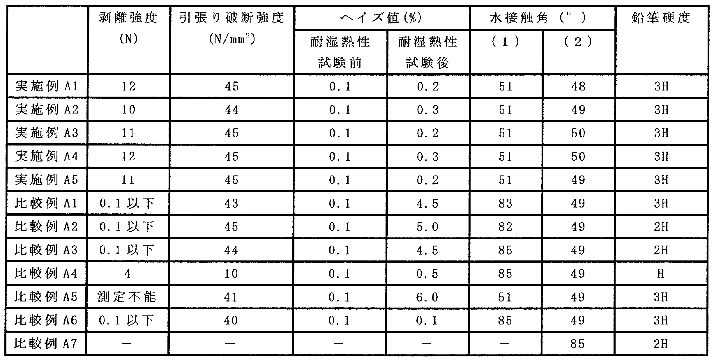
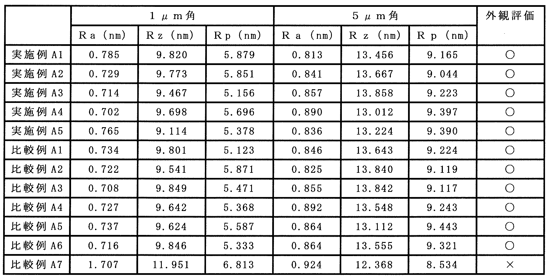

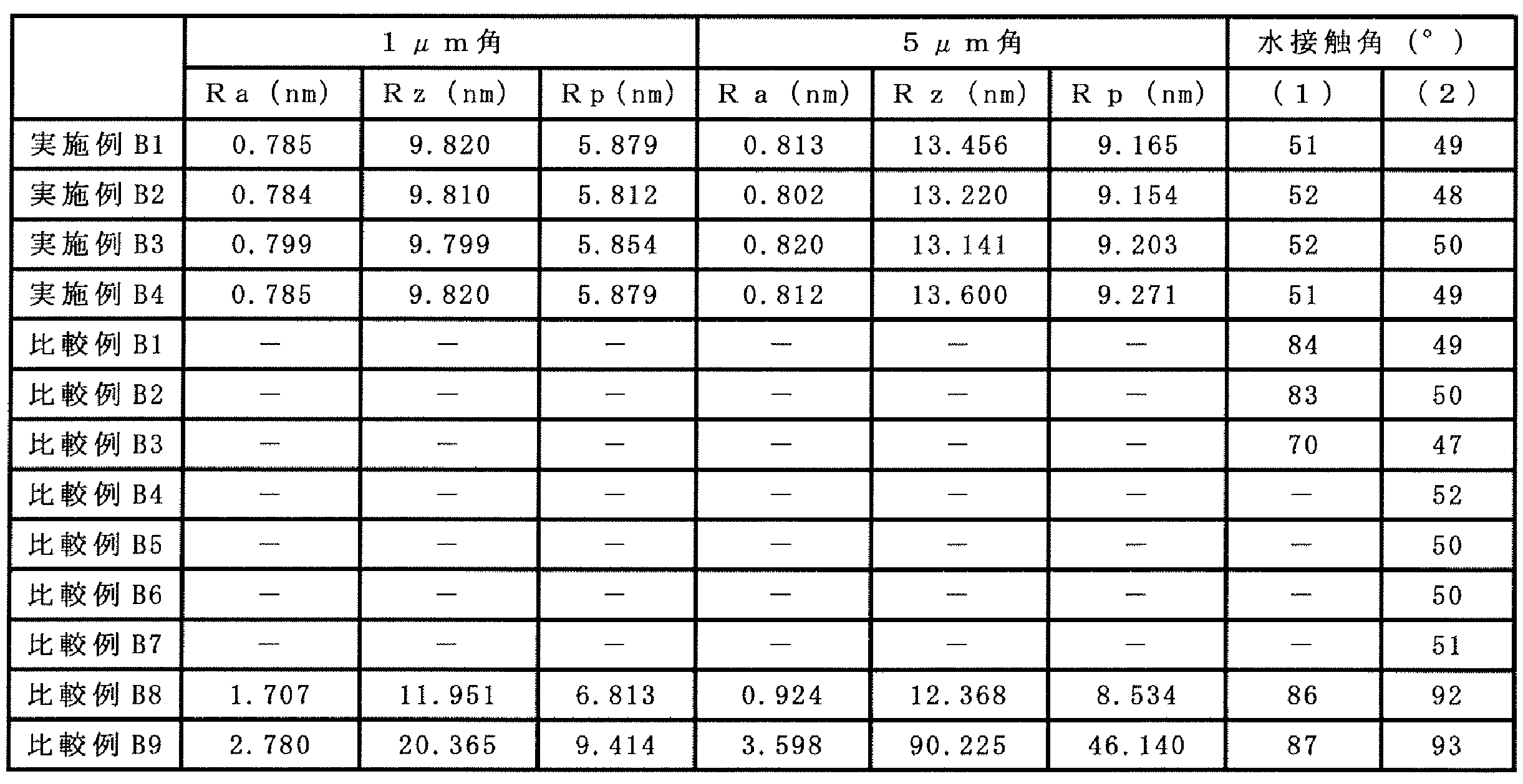
20…保護フィルム
20A、20B、120A、120B…表面
21、121…コア層
22…接着性向上層
23、123…光透過性機能層
30、130…離型フィルム
40、140…偏光板
41、141…偏光子
44、144…保護フィルム
50、150…画像表示装置
60…表示パネル
61…表示素子
70…タッチパネル
120…光学フィルム
122…析出抑制層
Claims (20)
- 偏光板に用いられる基材レスの保護フィルムであって、
硬化物からなる樹脂を含むコア層と、
前記コア層の一方の面に設けられた接着性向上層と
を備え、
前記接着性向上層の表面が前記保護フィルムの一方の表面をなし、かつ前記保護フィルムの厚みが40μm未満であり、
前記保護フィルムの引張り破断強度が30N/mm2以上である、保護フィルム。 - 鹸化処理後の前記接着性向上層の表面における水に対する接触角が、80°以下である、請求項1に記載の保護フィルム。
- 前記接着性向上層が、電離放射線重合性化合物と、反応性官能基および加水分解性基を有するシランカップリング剤とを含む硬化性組成物の硬化物である、請求項1に記載の保護フィルム。
- 前記電離放射線重合性化合物が、多官能電離放射線重合性化合物である、請求項3に記載の保護フィルム。
- 前記反応性官能基が、電離放射線重合性官能基である、請求項3に記載の保護フィルム。
- 前記コア層における前記一方の面とは反対側の他方の面に設けられた光透過性機能層をさらに備える、請求項1に記載の保護フィルム。
- 請求項1に記載の保護フィルムと、
前記保護フィルムにおける前記一方の表面とは反対側の他方の表面に設けられた離型フィルムと
を備える、積層体。 - 請求項1に記載の保護フィルムと、
前記保護フィルムの前記接着性向上層に、接着剤を介して貼り合わせられた偏光子と
を備える偏光板。 - 表示パネルを備える画像表示装置であって、
前記表示パネルが、表示素子と、前記表示素子よりも観察者側に配置された請求項1に記載の保護フィルムまたは請求項8に記載の偏光板とを備える、画像表示装置。 - 請求項7に記載の積層体の前記接着性向上層に接着剤が接するように、前記積層体と偏光子とを前記接着剤を介して貼り合わせる工程と、
前記積層体と前記偏光子とを貼り合わせた後、前記積層体から前記離型フィルムを剥離する工程と
を備える、偏光板の製造方法。 - 前記積層体と前記偏光子とを貼り合せる前に、前記積層体に鹸化処理を施す工程をさらに備える、請求項10に記載の偏光板の製造方法。
- 基材レスの光学フィルムであって、
硬化物からなるバインダ樹脂、および前記バインダ樹脂中に分散された紫外線吸収剤を含むコア層と、
前記コア層の一方の面に設けられ、かつ前記紫外線吸収剤の析出を抑制する析出抑制層と、を備え、
前記光学フィルムの厚みが40μm未満であり、
前記光学フィルムの引張り破断強度が30N/mm2以上である、光学フィルム。 - 前記析出抑制層が、多官能電離放射線重合性化合物の硬化物からなる樹脂を含む、請求項12に記載の光学フィルム。
- 前記析出抑制層が、シランカップリング剤をさらに含む、請求項13に記載の光学フィルム。
- 前記コア層における前記一方の面とは反対側の他方の面に設けられた光透過性機能層をさらに備える、請求項12に記載の光学フィルム。
- 請求項12に記載の光学フィルムと、
前記光学フィルムにおける析出抑制層側の表面とは反対側の表面に設けられた離型フィルムと
を備える、積層体。 - 請求項12に記載の光学フィルムと、
前記光学フィルムの前記析出抑制層に、接着剤を介して貼り合わせられた偏光子と
を備える偏光板。 - 表示パネルを備える画像表示装置であって、
前記表示パネルが、表示素子と、前記表示素子よりも観察者側に配置された請求項12に記載の光学フィルムまたは請求項17に記載の偏光板とを備える、画像表示装置。 - 請求項16に記載の積層体の前記析出抑制層に接着剤が接するように、前記積層体と偏光子とを前記接着剤を介して貼り合わせる工程と、
前記積層体と前記偏光子とを貼り合わせた後、前記離型フィルムを剥離する工程と
を備える、偏光板の製造方法。 - 前記積層体と前記偏光子とを貼り合せる前に、前記積層体に鹸化処理を施す工程をさらに備える、請求項19に記載の偏光板の製造方法。
Priority Applications (4)
| Application Number | Priority Date | Filing Date | Title |
|---|---|---|---|
| KR1020187031560A KR102339639B1 (ko) | 2016-04-07 | 2017-03-31 | 보호 필름, 광학 필름, 적층체, 편광판, 화상 표시 장치 및 편광판의 제조 방법 |
| JP2018510575A JP6950680B2 (ja) | 2016-04-07 | 2017-03-31 | 保護フィルム、光学フィルム、積層体、偏光板、画像表示装置、および偏光板の製造方法 |
| US16/091,249 US11312794B2 (en) | 2016-04-07 | 2017-03-31 | Protective film, optical film, laminate, polarizing plate, image display device and method for producing polarizing plate |
| CN201780034668.XA CN109313300B (zh) | 2016-04-07 | 2017-03-31 | 保护膜、光学膜、层积体、偏振片、图像显示装置以及偏振片的制造方法 |
Applications Claiming Priority (4)
| Application Number | Priority Date | Filing Date | Title |
|---|---|---|---|
| JP2016-077045 | 2016-04-07 | ||
| JP2016077045 | 2016-04-07 | ||
| JP2016-077044 | 2016-04-07 | ||
| JP2016077044 | 2016-04-07 |
Publications (1)
| Publication Number | Publication Date |
|---|---|
| WO2017175674A1 true WO2017175674A1 (ja) | 2017-10-12 |
Family
ID=60001152
Family Applications (1)
| Application Number | Title | Priority Date | Filing Date |
|---|---|---|---|
| PCT/JP2017/013557 Ceased WO2017175674A1 (ja) | 2016-04-07 | 2017-03-31 | 保護フィルム、光学フィルム、積層体、偏光板、画像表示装置、および偏光板の製造方法 |
Country Status (6)
| Country | Link |
|---|---|
| US (1) | US11312794B2 (ja) |
| JP (1) | JP6950680B2 (ja) |
| KR (1) | KR102339639B1 (ja) |
| CN (1) | CN109313300B (ja) |
| TW (2) | TWI834599B (ja) |
| WO (1) | WO2017175674A1 (ja) |
Cited By (5)
| Publication number | Priority date | Publication date | Assignee | Title |
|---|---|---|---|---|
| JP2019079053A (ja) * | 2017-10-25 | 2019-05-23 | 東洋紡株式会社 | 偏光子保護フィルム、偏光板及び画像表示装置 |
| WO2020079875A1 (ja) * | 2018-10-18 | 2020-04-23 | 日東電工株式会社 | カバーガラス付光学積層体およびカバーガラス付画像表示装置 |
| JP2020067653A (ja) * | 2018-10-18 | 2020-04-30 | 日東電工株式会社 | カバーガラス付光学積層体およびカバーガラス付画像表示装置 |
| JP2021033058A (ja) * | 2019-08-23 | 2021-03-01 | コニカミノルタ株式会社 | 光学フィルム用ドープの製造方法、光学フィルム用ドープ、光学フィルム、偏光板および光学フィルムの製造方法 |
| KR20210121173A (ko) * | 2020-03-10 | 2021-10-07 | 가부시키가이샤 도판 도모에가와 옵티컬 필름 | 편광판 및 이것을 사용한 표시 장치 |
Families Citing this family (5)
| Publication number | Priority date | Publication date | Assignee | Title |
|---|---|---|---|---|
| US20220221620A1 (en) * | 2017-03-17 | 2022-07-14 | Ian Contreras | Eyeglass lens protector system |
| CN117388969A (zh) | 2018-12-28 | 2024-01-12 | 大日本印刷株式会社 | 光学膜、偏振片、图像显示装置 |
| US11435620B2 (en) * | 2020-12-30 | 2022-09-06 | Nano And Advanced Materials Institute Limited | Quantum dot light source liquid crystal displays |
| KR102910766B1 (ko) * | 2021-12-17 | 2026-01-09 | 엘지디스플레이 주식회사 | 표시장치 |
| KR102741896B1 (ko) * | 2022-01-25 | 2024-12-16 | 동우 화인켐 주식회사 | 광학 적층체 및 이의 제조방법과, 이를 포함하는 스마트 윈도우 |
Citations (3)
| Publication number | Priority date | Publication date | Assignee | Title |
|---|---|---|---|---|
| JP2013105134A (ja) * | 2011-11-16 | 2013-05-30 | Dainippon Printing Co Ltd | 偏光子保護用光学フィルムおよび偏光板の製造方法 |
| JP2014130298A (ja) * | 2012-12-30 | 2014-07-10 | Tomoegawa Paper Co Ltd | 転写媒体、偏光板、および画像表示装置 |
| JP2016030331A (ja) * | 2014-07-25 | 2016-03-07 | 富士フイルム株式会社 | 積層フィルム、光学フィルム、偏光子保護フィルム、偏光板、画像表示装置及び積層フィルムの製造方法 |
Family Cites Families (20)
| Publication number | Priority date | Publication date | Assignee | Title |
|---|---|---|---|---|
| JP4659265B2 (ja) | 2001-05-02 | 2011-03-30 | 株式会社カネカ | 偏光子保護フィルムおよび偏光板 |
| JP2005189623A (ja) | 2003-12-26 | 2005-07-14 | Kaneka Corp | 偏光子保護フィルム |
| JP2006268065A (ja) * | 2004-08-05 | 2006-10-05 | Nitto Denko Corp | 位相差フィルム、光学フィルム、画像表示装置、液晶パネル及び液晶表示装置 |
| JP2006163082A (ja) | 2004-12-08 | 2006-06-22 | Nippon Paper Chemicals Co Ltd | 光学部材及びその製造方法、並びに液晶表示装置 |
| JPWO2006118038A1 (ja) * | 2005-04-28 | 2008-12-18 | コニカミノルタオプト株式会社 | 光学フィルム、偏光板及び横電界スイッチングモード型液晶表示装置 |
| JP4695439B2 (ja) * | 2005-05-31 | 2011-06-08 | 株式会社カネカ | 偏光子保護フィルムならびにそれを用いた偏光板 |
| JP2009036797A (ja) | 2007-07-31 | 2009-02-19 | Nitto Denko Corp | 光学フィルム、偏光板、および画像表示装置 |
| JP2008282020A (ja) | 2008-05-12 | 2008-11-20 | Nitto Denko Corp | 光学補償板、それを用いた光学補償層付偏光板、前記光学補償板の製造方法、および、それらを用いた液晶表示装置 |
| JP5324316B2 (ja) * | 2008-05-27 | 2013-10-23 | 日東電工株式会社 | 粘着型偏光板、画像表示装置およびそれらの製造方法 |
| WO2011142433A1 (ja) * | 2010-05-12 | 2011-11-17 | 大日本印刷株式会社 | 光学積層体、光学積層体の製造方法、偏光板及び画像表示装置 |
| JP5553362B2 (ja) | 2010-09-20 | 2014-07-16 | エルジー・ケム・リミテッド | 光学フィルムおよび偏光板 |
| JP5644397B2 (ja) * | 2010-11-11 | 2014-12-24 | 富士通株式会社 | 無線装置及びアンテナ装置 |
| JP5814018B2 (ja) | 2011-07-08 | 2015-11-17 | 住友化学株式会社 | 偏光板の製造方法 |
| JP5051328B1 (ja) * | 2012-01-27 | 2012-10-17 | 大日本印刷株式会社 | 光学積層体、偏光板及び画像表示装置 |
| JP5825147B2 (ja) * | 2012-03-01 | 2015-12-02 | 東亞合成株式会社 | 偏光板の製造方法 |
| JP6364008B2 (ja) * | 2013-07-16 | 2018-07-25 | 株式会社カネカ | 有機・無機基材被覆用活性エネルギー線硬化性樹脂組成物 |
| JP5996516B2 (ja) * | 2013-11-29 | 2016-09-21 | 住友化学株式会社 | 偏光子及びそれを含む偏光板 |
| WO2015159552A1 (ja) * | 2014-04-18 | 2015-10-22 | 株式会社クラレ | メタクリル樹脂組成物、成形体、フィルムおよび偏光板 |
| JP6683415B2 (ja) * | 2014-10-01 | 2020-04-22 | 株式会社日本触媒 | 光学フィルムおよびその利用 |
| JP6323477B2 (ja) * | 2016-02-29 | 2018-05-16 | 住友化学株式会社 | 偏光板のセットおよび液晶パネル |
-
2017
- 2017-03-31 KR KR1020187031560A patent/KR102339639B1/ko active Active
- 2017-03-31 TW TW106110950A patent/TWI834599B/zh active
- 2017-03-31 CN CN201780034668.XA patent/CN109313300B/zh active Active
- 2017-03-31 WO PCT/JP2017/013557 patent/WO2017175674A1/ja not_active Ceased
- 2017-03-31 TW TW111132344A patent/TWI835262B/zh active
- 2017-03-31 US US16/091,249 patent/US11312794B2/en active Active
- 2017-03-31 JP JP2018510575A patent/JP6950680B2/ja active Active
Patent Citations (3)
| Publication number | Priority date | Publication date | Assignee | Title |
|---|---|---|---|---|
| JP2013105134A (ja) * | 2011-11-16 | 2013-05-30 | Dainippon Printing Co Ltd | 偏光子保護用光学フィルムおよび偏光板の製造方法 |
| JP2014130298A (ja) * | 2012-12-30 | 2014-07-10 | Tomoegawa Paper Co Ltd | 転写媒体、偏光板、および画像表示装置 |
| JP2016030331A (ja) * | 2014-07-25 | 2016-03-07 | 富士フイルム株式会社 | 積層フィルム、光学フィルム、偏光子保護フィルム、偏光板、画像表示装置及び積層フィルムの製造方法 |
Cited By (10)
| Publication number | Priority date | Publication date | Assignee | Title |
|---|---|---|---|---|
| JP2019079053A (ja) * | 2017-10-25 | 2019-05-23 | 東洋紡株式会社 | 偏光子保護フィルム、偏光板及び画像表示装置 |
| JP7243126B2 (ja) | 2017-10-25 | 2023-03-22 | 東洋紡株式会社 | 偏光子保護フィルム、偏光板及び画像表示装置 |
| WO2020079875A1 (ja) * | 2018-10-18 | 2020-04-23 | 日東電工株式会社 | カバーガラス付光学積層体およびカバーガラス付画像表示装置 |
| JP2020067653A (ja) * | 2018-10-18 | 2020-04-30 | 日東電工株式会社 | カバーガラス付光学積層体およびカバーガラス付画像表示装置 |
| JP2021033058A (ja) * | 2019-08-23 | 2021-03-01 | コニカミノルタ株式会社 | 光学フィルム用ドープの製造方法、光学フィルム用ドープ、光学フィルム、偏光板および光学フィルムの製造方法 |
| JP7379933B2 (ja) | 2019-08-23 | 2023-11-15 | コニカミノルタ株式会社 | 光学フィルム用ドープの製造方法および光学フィルムの製造方法 |
| KR20210121173A (ko) * | 2020-03-10 | 2021-10-07 | 가부시키가이샤 도판 도모에가와 옵티컬 필름 | 편광판 및 이것을 사용한 표시 장치 |
| KR102625719B1 (ko) * | 2020-03-10 | 2024-01-17 | 가부시키가이샤 도판 도모에가와 옵티컬 필름 | 편광판 및 이것을 사용한 표시 장치 |
| KR20240009540A (ko) * | 2020-03-10 | 2024-01-22 | 가부시키가이샤 도판 도모에가와 옵티컬 필름 | 편광판 및 이것을 사용한 표시 장치 |
| KR102827544B1 (ko) * | 2020-03-10 | 2025-07-01 | 가부시키가이샤 도판 도모에가와 옵티컬 필름 | 편광판 및 이것을 사용한 표시 장치 |
Also Published As
| Publication number | Publication date |
|---|---|
| US20190196075A1 (en) | 2019-06-27 |
| TW201806764A (zh) | 2018-03-01 |
| JPWO2017175674A1 (ja) | 2019-03-07 |
| CN109313300A (zh) | 2019-02-05 |
| KR20180133874A (ko) | 2018-12-17 |
| TWI835262B (zh) | 2024-03-11 |
| TWI834599B (zh) | 2024-03-11 |
| KR102339639B1 (ko) | 2021-12-15 |
| TW202300336A (zh) | 2023-01-01 |
| CN109313300B (zh) | 2021-10-01 |
| JP6950680B2 (ja) | 2021-10-13 |
| US11312794B2 (en) | 2022-04-26 |
Similar Documents
| Publication | Publication Date | Title |
|---|---|---|
| JP6950680B2 (ja) | 保護フィルム、光学フィルム、積層体、偏光板、画像表示装置、および偏光板の製造方法 | |
| JP7571832B2 (ja) | 光学フィルム、偏光板、および画像表示装置 | |
| JP6935463B2 (ja) | 偏光板用保護フィルム及びそれを用いた偏光板 | |
| CN111989597B (zh) | 功能性膜、偏振片和图像显示装置 | |
| CN103080778B (zh) | 光学层叠体、偏振片和图像显示装置 | |
| JP6237796B2 (ja) | 光学積層体、偏光板及び画像表示装置 | |
| CN104854491B (zh) | 光学层叠体、使用其的偏振片及图像显示装置 | |
| CN111183374A (zh) | 硬涂薄膜、光学层叠体及图像显示装置 | |
| CN108431641B (zh) | 光学膜、偏振膜、偏振膜的制造方法以及图像显示装置 | |
| JPWO2017119391A1 (ja) | 光学フィルム、偏光板および画像表示装置 | |
| JPWO2019035398A1 (ja) | 光学フィルム、偏光板、および画像表示装置 | |
| JP6443069B2 (ja) | 光学積層体 | |
| JP6551117B2 (ja) | 光学積層体及びその製造方法 | |
| JP2013209483A (ja) | 高屈折率アンチブロッキング層形成組成物 | |
| JP7147121B2 (ja) | 保護フィルム、積層体、偏光板、および画像表示装置 | |
| JP4858369B2 (ja) | ハードコートフィルムもしくはシート | |
| WO2025178033A1 (ja) | 光学積層体、表示装置用部材および表示装置 | |
| JP2022179511A (ja) | 光学積層体及び表示装置 |
Legal Events
| Date | Code | Title | Description |
|---|---|---|---|
| ENP | Entry into the national phase |
Ref document number: 2018510575 Country of ref document: JP Kind code of ref document: A |
|
| NENP | Non-entry into the national phase |
Ref country code: DE |
|
| ENP | Entry into the national phase |
Ref document number: 20187031560 Country of ref document: KR Kind code of ref document: A |
|
| 121 | Ep: the epo has been informed by wipo that ep was designated in this application |
Ref document number: 17779053 Country of ref document: EP Kind code of ref document: A1 |
|
| 122 | Ep: pct application non-entry in european phase |
Ref document number: 17779053 Country of ref document: EP Kind code of ref document: A1 |