WO2017170492A1 - インダクタ用接着剤及びインダクタ - Google Patents
インダクタ用接着剤及びインダクタ Download PDFInfo
- Publication number
- WO2017170492A1 WO2017170492A1 PCT/JP2017/012547 JP2017012547W WO2017170492A1 WO 2017170492 A1 WO2017170492 A1 WO 2017170492A1 JP 2017012547 W JP2017012547 W JP 2017012547W WO 2017170492 A1 WO2017170492 A1 WO 2017170492A1
- Authority
- WO
- WIPO (PCT)
- Prior art keywords
- adhesive
- inductor
- less
- weight
- particles
- Prior art date
- Legal status (The legal status is an assumption and is not a legal conclusion. Google has not performed a legal analysis and makes no representation as to the accuracy of the status listed.)
- Ceased
Links
Images

Classifications
-
- C—CHEMISTRY; METALLURGY
- C09—DYES; PAINTS; POLISHES; NATURAL RESINS; ADHESIVES; COMPOSITIONS NOT OTHERWISE PROVIDED FOR; APPLICATIONS OF MATERIALS NOT OTHERWISE PROVIDED FOR
- C09J—ADHESIVES; NON-MECHANICAL ASPECTS OF ADHESIVE PROCESSES IN GENERAL; ADHESIVE PROCESSES NOT PROVIDED FOR ELSEWHERE; USE OF MATERIALS AS ADHESIVES
- C09J11/00—Features of adhesives not provided for in group C09J9/00, e.g. additives
- C09J11/02—Non-macromolecular additives
- C09J11/04—Non-macromolecular additives inorganic
-
- C—CHEMISTRY; METALLURGY
- C09—DYES; PAINTS; POLISHES; NATURAL RESINS; ADHESIVES; COMPOSITIONS NOT OTHERWISE PROVIDED FOR; APPLICATIONS OF MATERIALS NOT OTHERWISE PROVIDED FOR
- C09J—ADHESIVES; NON-MECHANICAL ASPECTS OF ADHESIVE PROCESSES IN GENERAL; ADHESIVE PROCESSES NOT PROVIDED FOR ELSEWHERE; USE OF MATERIALS AS ADHESIVES
- C09J11/00—Features of adhesives not provided for in group C09J9/00, e.g. additives
- C09J11/02—Non-macromolecular additives
- C09J11/06—Non-macromolecular additives organic
-
- C—CHEMISTRY; METALLURGY
- C09—DYES; PAINTS; POLISHES; NATURAL RESINS; ADHESIVES; COMPOSITIONS NOT OTHERWISE PROVIDED FOR; APPLICATIONS OF MATERIALS NOT OTHERWISE PROVIDED FOR
- C09J—ADHESIVES; NON-MECHANICAL ASPECTS OF ADHESIVE PROCESSES IN GENERAL; ADHESIVE PROCESSES NOT PROVIDED FOR ELSEWHERE; USE OF MATERIALS AS ADHESIVES
- C09J11/00—Features of adhesives not provided for in group C09J9/00, e.g. additives
- C09J11/08—Macromolecular additives
-
- C—CHEMISTRY; METALLURGY
- C09—DYES; PAINTS; POLISHES; NATURAL RESINS; ADHESIVES; COMPOSITIONS NOT OTHERWISE PROVIDED FOR; APPLICATIONS OF MATERIALS NOT OTHERWISE PROVIDED FOR
- C09J—ADHESIVES; NON-MECHANICAL ASPECTS OF ADHESIVE PROCESSES IN GENERAL; ADHESIVE PROCESSES NOT PROVIDED FOR ELSEWHERE; USE OF MATERIALS AS ADHESIVES
- C09J201/00—Adhesives based on unspecified macromolecular compounds
-
- H—ELECTRICITY
- H01—ELECTRIC ELEMENTS
- H01F—MAGNETS; INDUCTANCES; TRANSFORMERS; SELECTION OF MATERIALS FOR THEIR MAGNETIC PROPERTIES
- H01F17/00—Fixed inductances of the signal type
- H01F17/04—Fixed inductances of the signal type with magnetic core
-
- H—ELECTRICITY
- H01—ELECTRIC ELEMENTS
- H01F—MAGNETS; INDUCTANCES; TRANSFORMERS; SELECTION OF MATERIALS FOR THEIR MAGNETIC PROPERTIES
- H01F27/00—Details of transformers or inductances, in general
- H01F27/24—Magnetic cores
-
- H—ELECTRICITY
- H01—ELECTRIC ELEMENTS
- H01F—MAGNETS; INDUCTANCES; TRANSFORMERS; SELECTION OF MATERIALS FOR THEIR MAGNETIC PROPERTIES
- H01F30/00—Fixed transformers not covered by group H01F19/00
-
- H—ELECTRICITY
- H01—ELECTRIC ELEMENTS
- H01F—MAGNETS; INDUCTANCES; TRANSFORMERS; SELECTION OF MATERIALS FOR THEIR MAGNETIC PROPERTIES
- H01F37/00—Fixed inductances not covered by group H01F17/00
-
- C—CHEMISTRY; METALLURGY
- C09—DYES; PAINTS; POLISHES; NATURAL RESINS; ADHESIVES; COMPOSITIONS NOT OTHERWISE PROVIDED FOR; APPLICATIONS OF MATERIALS NOT OTHERWISE PROVIDED FOR
- C09J—ADHESIVES; NON-MECHANICAL ASPECTS OF ADHESIVE PROCESSES IN GENERAL; ADHESIVE PROCESSES NOT PROVIDED FOR ELSEWHERE; USE OF MATERIALS AS ADHESIVES
- C09J2301/00—Additional features of adhesives in the form of films or foils
- C09J2301/30—Additional features of adhesives in the form of films or foils characterized by the chemical, physicochemical or physical properties of the adhesive or the carrier
- C09J2301/312—Additional features of adhesives in the form of films or foils characterized by the chemical, physicochemical or physical properties of the adhesive or the carrier parameters being the characterizing feature
Definitions
- the present invention relates to an inductor adhesive used for an inductor.
- the present invention also relates to an inductor using the inductor adhesive.
- Inductors are used in electronic devices such as mobile phones, televisions, and digital cameras.
- a core material such as a ferrite core is disposed with a gap.
- an adhesive that does not include particles or an adhesive that includes particles such as glass beads is used in the gap (adhesive portion).
- Patent Document 1 discloses an adhesive containing non-magnetic particles (particles).
- glass beads are used as the particles.
- Patent Document 2 discloses an adhesive containing spacer particles having a CV value of 10% or less.
- resin particles are used as the particles.
- the adhesiveness may be lowered because the thickness of the bonded portion (gap portion interval) cannot be controlled with high accuracy. Furthermore, moisture resistance may be low in an adhesive part (gap part) formed using an adhesive.
- cracks may occur in the ferrite core, or the inductance may decrease compared to the initial value, and the performance of the inductor may deteriorate.
- An object of the present invention is to provide an inductor adhesive that can increase moisture resistance and can suppress a decrease in adhesiveness even when exposed to high humidity. Moreover, the objective of this invention is providing the inductor using the said adhesive agent for inductors.
- an adhesive for an inductor used for an inductor which includes a thermosetting compound, a thermosetting agent, an inorganic filler, and spacer particles, and the spacer particles are resin particles or organic.
- Inorganic hybrid particles wherein the spacer particles have an average particle size of 20 ⁇ m or more and 200 ⁇ m or less, the spacer particles have a CV value of 10% or less, and the inorganic filler in 100% by weight of the adhesive.
- An inductor adhesive (hereinafter, “inductor adhesive” may be referred to as “adhesive”) is provided in which the content of is more than 30 wt% and 75 wt% or less.
- the glass transition point of the obtained cured product when the adhesive is heated at 120 ° C. for 20 minutes and then heated at 170 ° C. for 15 minutes to obtain a cured product, the glass transition point of the obtained cured product.
- the temperature is 120 ° C. or higher and 210 ° C. or lower.
- the adhesive according to the present invention after placing 30 mg of the adhesive on the first slide glass, placing the second slide glass on the adhesive, 50 g on the second slide glass.
- the number of the spacer particles is 2 / mm 2 or more and 1000 / mm 2 or less in plan view.
- the content of the thermosetting agent is 0.01 parts by weight or more and 10 parts by weight or less with respect to 100 parts by weight of the thermosetting compound.
- the viscosity of the adhesive at 25 ° C. is 10 Pa ⁇ s or more and 150 Pa ⁇ s or less.
- the content of the spacer particles is 1 wt% or more and 15 wt% or less in 100 wt% of the adhesive.
- a ratio of the content of the inorganic filler in 100% by weight of the adhesive to the content of the spacer particles in 100% by weight of the adhesive is 3 or more, 60 It is as follows.
- the ratio of the average particle diameter of the inorganic filler to the average particle diameter of the spacer particles is 0.00005 or more and 0.1 or less.
- 10% K value of the spacer particles is 980 N / mm 2 or more and 4900 N / mm 2 less.
- the inductor adhesive is used for bonding a ferrite core in an inductor.
- an inductor comprising a ferrite core and an adhesive part that adheres the ferrite core, wherein the material of the adhesive part is the above-described adhesive for an inductor.
- the inductor adhesive according to the present invention includes a thermosetting compound, a thermosetting agent, an inorganic filler, and spacer particles, and the spacer particles are resin particles or organic-inorganic hybrid particles.
- the average particle diameter is 20 ⁇ m or more and 200 ⁇ m or less
- the CV value of the particle diameter of the spacer particles is 10% or less
- the content of the inorganic filler exceeds 30% by weight in 100% by weight of the adhesive, Since it is 75 weight% or less, moisture resistance can be made high and even if it exposes to high humidity, the fall of adhesiveness can be suppressed.
- FIG. 1 is a cross-sectional view schematically showing an inductor using an inductor adhesive according to an embodiment of the present invention.
- the adhesive for inductors according to the present invention (hereinafter sometimes abbreviated as adhesive) is used for inductors.
- the adhesive according to the present invention includes a thermosetting compound, a thermosetting agent, an inorganic filler, and spacer particles.
- the spacer particles are resin particles or organic-inorganic hybrid particles.
- the spacer particles have an average particle size of 20 ⁇ m or more and 200 ⁇ m or less.
- the CV value of the particle diameter of the spacer particles is 10% or less.
- the content of the inorganic filler is more than 30% by weight and 75% by weight or less.
- the adhesive portion formed by the adhesive is difficult to absorb water, and even if it is exposed to high humidity, a decrease in adhesiveness can be suppressed.
- the uniformity of the thickness of the bonded portion can be improved, excellent adhesiveness can be exhibited, and variation in inductance can be suppressed.
- the thermal shock resistance can be increased, and the thermal shock resistance (long-term reliability) of the inductor can be increased. Even if the inductor is exposed to a high temperature or a low temperature, or is subjected to a thermal cycle, the change in inductance can be reduced.
- the average particle diameter of the spacer particles is 20 ⁇ m or more and 200 ⁇ m or less. From the viewpoint of further improving the adhesiveness, the average particle diameter of the spacer particles is preferably 25 ⁇ m or more, more preferably 30 ⁇ m or more, preferably 150 ⁇ m or less, more preferably 130 ⁇ m or less.
- the ratio of the average particle diameter of the inorganic filler to the average particle diameter of the spacer particles is preferably 0.1 or less. More preferably, it is 0.01 or less. From the viewpoint of further improving the moisture resistance, the above ratio (average particle diameter of inorganic filler / average particle diameter of spacer particles) is preferably 0.00005 or more, more preferably 0.0005 or more.
- the above average particle diameter indicates the number average particle diameter.
- the average particle diameter of the inorganic filler and the spacer particles can be obtained, for example, by observing 50 arbitrary inorganic fillers or 50 arbitrary spacer particles with an electron microscope or an optical microscope and calculating an average value.
- the CV value of the particle diameter of the spacer particles is 10% or less. From the viewpoint of further improving the adhesiveness, the CV value of the particle diameter of the spacer particles is preferably 1% or more, and preferably 5% or less.
- the CV value (coefficient of variation) is expressed by the following formula.
- CV value (%) ( ⁇ / Dn) ⁇ 100 ⁇ : Standard deviation of spacer particle diameter Dn: Average value of spacer particle diameter
- the viscosity of the adhesive at 25 ° C is: Preferably it is 10 Pa ⁇ s or more, more preferably 15 Pa ⁇ s or more, preferably 150 Pa ⁇ s or less, more preferably 100 Pa ⁇ s or less, still more preferably 70 Pa ⁇ s or less, particularly preferably 40 Pa ⁇ s or less, and most preferably Is 35 Pa ⁇ s or less.
- the viscosity ( ⁇ 25) is measured using, for example, an E-type viscometer (“TVE22L” manufactured by Toki Sangyo Co., Ltd.) and the like, and a spiral viscometer (“PCU-02V” manufactured by Malcolm). And can be measured at 25 ° C. and 10 rpm.
- an E-type viscometer (“TVE22L” manufactured by Toki Sangyo Co., Ltd.) is preferably used.
- a spiral viscometer (“PCU-02V” manufactured by Malcolm) is preferably used.
- the glass transition temperature of the obtained cured product is Preferably it is 120 degreeC or more, Preferably it is 210 degrees C or less.
- the adhesive agent which concerns on this invention, after heating at 120 degreeC for 20 minutes, you may heat on conditions other than the conditions heated at 170 degreeC for 15 minutes.
- the adhesive is placed on the first slide glass, and the second slide glass is placed on the adhesive.
- the number of the spacer particles is preferably 2 / mm 2 or more, preferably 1000 in plan view. / Mm 2 or less. In the observation in the plan view, the adhesive between the first and second slide glasses is observed.
- the adhesive is heated at 120 ° C. for 20 minutes and then heated at 170 ° C. for 15 minutes to obtain a cured product.
- the linear expansion coefficient of the cured product obtained is preferably 60 ppm or less, more preferably 50 ppm or less, still more preferably 40 ppm or less, and particularly preferably 30 ppm or less.
- the above adhesive is suitably used for bonding a ferrite core in an inductor.
- thermosetting compound contained in the adhesive is not particularly limited.
- the thermosetting compound is a compound that can be cured by heating.
- As for the said thermosetting compound only 1 type may be used and 2 or more types may be used together.
- thermosetting compound preferably contains an epoxy compound.
- thermosetting compound preferably has an aromatic skeleton.
- the aromatic skeleton examples include a benzene skeleton, naphthalene skeleton, fluorene skeleton, biphenyl skeleton, anthracene skeleton, pyrene skeleton, xanthene skeleton, adamantane skeleton, and bisphenol A skeleton.
- the aromatic skeleton is preferably a benzene skeleton, a naphthalene skeleton, or a fluorene skeleton, and more preferably a naphthalene skeleton.
- the aromatic skeleton may be a benzene skeleton or a naphthalene skeleton.
- the thermosetting compound preferably includes a thermosetting compound having a naphthalene skeleton.
- the content of the thermosetting compound is preferably 0.01% by weight or more, more preferably 0.1% by weight or more, in 100% by weight of the adhesive. More preferably, it is 1% by weight or more, particularly preferably 15% by weight or more, preferably 90% by weight or less, more preferably 80% by weight or less, and further preferably 70% by weight or less.
- the content of the thermosetting compound having the naphthalene skeleton is preferably 0.01% by weight or more, more preferably 0.1% in 100% by weight of the adhesive.
- % By weight or more, more preferably 1% by weight or more, particularly preferably 15% by weight or more, preferably 90% by weight or less, more preferably 80% by weight or less, still more preferably 70% by weight or less, particularly preferably 50% by weight. % Or less, most preferably 30% by weight or less.
- thermosetting agent thermosets the thermosetting compound.
- examples of the thermosetting agent include an imidazole curing agent, a phenol curing agent, a thiol curing agent, an amine curing agent, an acid anhydride curing agent, a thermal cation initiator, and a thermal radical generator.
- the said thermosetting agent only 1 type may be used and 2 or more types may be used together.
- the imidazole curing agent is not particularly limited, and 2-methylimidazole, 2-ethyl-4-methylimidazole, 1-cyanoethyl-2-phenylimidazole, 1-cyanoethyl-2-phenylimidazolium trimellitate, 2, 4-Diamino-6- [2'-methylimidazolyl- (1 ')]-ethyl-s-triazine and 2,4-diamino-6- [2'-methylimidazolyl- (1')]-ethyl-s- Examples include triazine isocyanuric acid adducts.
- the thiol curing agent is not particularly limited, and examples thereof include trimethylolpropane tris-3-mercaptopropionate, pentaerythritol tetrakis-3-mercaptopropionate, and dipentaerythritol hexa-3-mercaptopropionate. .
- the solubility parameter of the thiol curing agent is preferably 9.5 or more, and preferably 12 or less.
- the solubility parameter is calculated by the Fedors method. For example, the solubility parameter of trimethylolpropane tris-3-mercaptopropionate is 9.6, and the solubility parameter of dipentaerythritol hexa-3-mercaptopropionate is 11.4.
- the amine curing agent is not particularly limited, and hexamethylenediamine, octamethylenediamine, decamethylenediamine, 3,9-bis (3-aminopropyl) -2,4,8,10-tetraspiro [5.5].
- examples include undecane, bis (4-aminocyclohexyl) methane, metaphenylenediamine, and diaminodiphenylsulfone.
- thermal cation initiator examples include iodonium cation curing agents, oxonium cation curing agents, and sulfonium cation curing agents.
- examples of the iodonium-based cationic curing agent include bis (4-tert-butylphenyl) iodonium hexafluorophosphate.
- examples of the oxonium-based cationic curing agent include trimethyloxonium tetrafluoroborate.
- sulfonium-based cationic curing agent examples include tri-p-tolylsulfonium hexafluorophosphate.
- the thermal radical generator is not particularly limited, and examples thereof include azo compounds and organic peroxides.
- examples of the azo compound include azobisisobutyronitrile (AIBN).
- examples of the organic peroxide include di-tert-butyl peroxide and methyl ethyl ketone peroxide.
- the content of the thermosetting agent is not particularly limited.
- the content of the thermosetting agent with respect to 100 parts by weight of the thermosetting compound is preferably 0.01 parts by weight or more, more preferably 1 part by weight or more, preferably 200 parts by weight or less, more preferably 100 parts by weight or less, more preferably 75 parts by weight or less, particularly preferably 50 parts by weight or less, and most preferably 10 parts by weight or less.
- the content of the thermosetting agent is not less than the above lower limit, it is easy to sufficiently cure the adhesive. If the content of the thermosetting agent is not more than the above upper limit, it becomes difficult for the surplus thermosetting agent that did not participate in curing after curing to remain, and the heat resistance of the bonded portion is further increased.
- the spacer particles include resin particles, inorganic particles excluding metal particles, organic-inorganic hybrid particles, and metal particles.
- the spacer particles are resin particles or organic-inorganic hybrid particles.
- the spacer particle may be a core-shell particle including a core and a shell disposed on the surface of the core.
- the core may be an organic core.
- the shell may be an inorganic shell. From the viewpoint of reducing stress when stress is applied to the bonded portion and maintaining high adhesion, spacer particles excluding metal particles are preferable, and resin particles, inorganic particles excluding metal particles, or organic-inorganic hybrid particles are more preferable. preferable.
- resin particles or organic-inorganic hybrid particles are used because they are more excellent due to the effects of the present invention.
- the spacer particles are preferably resin particles formed of resin.
- the spacer particles are resin particles, when stress is applied to the bonding portion, the stress can be relaxed and the adhesiveness can be maintained high.
- the resin for forming the resin particles include polyolefin resins such as polyethylene, polypropylene, polystyrene, polyvinyl chloride, polyvinylidene chloride, polyisobutylene, and polybutadiene; acrylic resins such as polymethyl methacrylate and polymethyl acrylate; Alkylene terephthalate, polycarbonate, polyamide, phenol formaldehyde resin, melamine formaldehyde resin, benzoguanamine formaldehyde resin, urea formaldehyde resin, phenol resin, melamine resin, benzoguanamine resin, urea resin, epoxy resin, unsaturated polyester resin, saturated polyester resin, polysulfone, polyphenylene Oxide, polyacetal, polyimide, polyamideimide, polyether ether Ketones, polyether sulfones, and polymers such as obtained by a variety of polymerizable monomer having an terephthalate, polyethylene, polypropylene, polystyrene
- the resin for forming the resin particles is a polymer obtained by polymerizing one or more polymerizable monomers having a plurality of ethylenically unsaturated groups. It is preferably a coalescence.
- the polymerizable monomer having an ethylenically unsaturated group may be a non-crosslinkable monomer or a crosslinkable monomer. And the monomer.
- non-crosslinkable monomer examples include styrene monomers such as styrene and ⁇ -methylstyrene; carboxyl group-containing monomers such as (meth) acrylic acid, maleic acid, and maleic anhydride; (Meth) acrylate, ethyl (meth) acrylate, propyl (meth) acrylate, butyl (meth) acrylate, 2-ethylhexyl (meth) acrylate, lauryl (meth) acrylate, cetyl (meth) acrylate, stearyl (meth) acrylate, cyclohexyl ( Alkyl (meth) acrylate compounds such as meth) acrylate and isobornyl (meth) acrylate; 2-hydroxyethyl (meth) acrylate, glycerol (meth) acrylate, polyoxyethylene (meth) acrylate, glycidyl (meth) acrylate, etc.
- Oxygen atom-containing (meth) acrylate compounds Nitrile-containing monomers such as (meth) acrylonitrile; Vinyl ether compounds such as methyl vinyl ether, ethyl vinyl ether, and propyl vinyl ether; Acids such as vinyl acetate, vinyl butyrate, vinyl laurate, and vinyl stearate Vinyl ester compounds; unsaturated hydrocarbons such as ethylene, propylene, isoprene, and butadiene; halogen-containing monomers such as trifluoromethyl (meth) acrylate, pentafluoroethyl (meth) acrylate, vinyl chloride, vinyl fluoride, and chlorostyrene Etc.
- Nitrile-containing monomers such as (meth) acrylonitrile
- Vinyl ether compounds such as methyl vinyl ether, ethyl vinyl ether, and propyl vinyl ether
- Acids such as vinyl acetate, vinyl butyrate, vinyl laurate, and vinyl stea
- crosslinkable monomer examples include tetramethylolmethane tetra (meth) acrylate, tetramethylolmethane tri (meth) acrylate, tetramethylolmethane di (meth) acrylate, trimethylolpropane tri (meth) acrylate, and dipenta Erythritol hexa (meth) acrylate, dipentaerythritol penta (meth) acrylate, glycerol tri (meth) acrylate, glycerol di (meth) acrylate, (poly) ethylene glycol di (meth) acrylate, (poly) propylene glycol di (meth) Polyfunctional (meth) acrylate compounds such as acrylate, (poly) tetramethylene glycol di (meth) acrylate, 1,4-butanediol di (meth) acrylate; triallyl (iso) sia Silane-
- the resin particles can be obtained by polymerizing the polymerizable monomer having an ethylenically unsaturated group by a known method. Examples of this method include a method of suspension polymerization in the presence of a radical polymerization initiator, and a method of polymerizing by swelling a monomer together with a radical polymerization initiator using non-crosslinked seed particles.
- examples of inorganic materials for forming the spacer particles include silica and carbon black.
- the inorganic substance is preferably not a metal.
- the particles formed from the silica are not particularly limited. For example, after forming a crosslinked polymer particle by hydrolyzing a silicon compound having two or more hydrolyzable alkoxysilyl groups, firing may be performed as necessary. The particle
- examples of the organic / inorganic hybrid particles include organic / inorganic hybrid particles formed of a crosslinked alkoxysilyl polymer and an acrylic resin.
- the compression elastic modulus (10% K value) when the spacer particles are compressed by 10% is preferably 980 N / mm 2 or more, more preferably 1200 N / mm 2. or more, preferably 4900 N / mm 2 or less, and more preferably not more than 3000N / mm 2.
- the 10% K value of the spacer particles can be measured as follows.
- spacer particles are compressed under a condition that a smooth tester end face of a cylinder (diameter 50 ⁇ m, made of diamond) is loaded at 25 ° C. and a maximum test load of 90 mN over 30 seconds.
- the load value (N) and compression displacement (mm) at this time are measured. From the measured value obtained, the compression elastic modulus can be obtained by the following formula.
- the micro compression tester for example, “Fischer Scope H-100” manufactured by Fischer is used.
- the content of the spacer particles in 100% by weight of the adhesive is preferably 1% by weight or more.
- it is 2 weight% or more, More preferably, it exceeds 5 weight%, Preferably it is 15 weight% or less, More preferably, it is 12 weight% or less.
- inorganic filler examples include silica, talc, clay, mica, hydrotalcite, alumina, magnesium oxide, aluminum hydroxide, aluminum nitride, and boron nitride.
- the inorganic filler is preferably silica or alumina, more preferably silica, and even more preferably fused silica.
- silica the thermal expansion coefficient of the bonded portion is further lowered, and the bonding reliability is further increased.
- the inorganic filler is preferably a surface-treated product with a coupling agent.
- the coupling agent examples include silane coupling agents, titanium coupling agents, and aluminum coupling agents.
- the inorganic filler is preferably a surface-treated product with a silane coupling agent.
- silane coupling agent examples include phenyl silane, vinyl silane, amino silane, imidazole silane, and epoxy silane. From the viewpoint of further improving the moisture resistance, phenylsilane is preferred.
- the content of the inorganic filler is more than 30% by weight and 75% by weight or less. From the viewpoint of further improving the moisture resistance, the content of the inorganic filler is preferably more than 35% by weight and more preferably 40% by weight or more in 100% by weight of the adhesive. From the viewpoint of further improving the adhesiveness, the content of the inorganic filler is preferably 70% by weight or less, more preferably 65% by weight or less, and still more preferably 60% by weight or less.
- the ratio of the content of the inorganic filler in 100% by weight of the adhesive to the content of the spacer particles in 100% by weight of the adhesive (inorganic filler) Content / spacer particle content) is preferably 3 or more, more preferably 4 or more, preferably 60 or less, more preferably 30 or less.
- the adhesive may contain a photocurable component, and may contain a photocurable compound and a photopolymerization initiator.
- the adhesive preferably contains a coupling agent.
- the coupling agent examples include silane coupling agents, titanium coupling agents, and aluminum coupling agents. From the viewpoint of further improving the adhesiveness, the adhesive preferably contains a silane coupling agent.
- silane coupling agent examples include phenyl silane, vinyl silane, amino silane, imidazole silane, and epoxy silane.
- the content of the coupling agent is preferably 0.01% by weight or more, more preferably 0.1% by weight or more, preferably 2% in 100% by weight of the adhesive. % By weight or less, more preferably 1% by weight or less.
- the above-mentioned adhesive contains a thixotropic agent. Is preferred.
- thixotropic agent examples include inorganic particles such as metal particles, calcium carbonate, fumed silica, aluminum oxide, boron nitride, aluminum nitride, and aluminum borate.
- the above-mentioned thixotropy is imparted in 100% by weight of the adhesive.
- the content of the agent is preferably 0.1% by weight or more, more preferably 0.5% by weight or more, preferably 10% by weight or less, more preferably 5% by weight or less.
- the adhesive may be, for example, a filler, an extender, a softener, a plasticizer, a polymerization catalyst, a curing catalyst, a colorant, an antioxidant, a heat stabilizer, a light stabilizer, an ultraviolet absorber, and a lubricant as necessary.
- various additives such as an antistatic agent and a flame retardant may be included.
- the inductor according to the present invention includes a ferrite core and an adhesive portion that adheres the ferrite core.
- the material of the upper bonding portion is the above-described inductor adhesive.
- the bonding portion is a cured product of the inductor adhesive.
- the adhesive portion is formed by curing the inductor adhesive.
- the ferrite core is disposed on the opposite surfaces of the adhesive portion. It is preferable that there is a gap in the ferrite core due to the adhesive portion.
- FIG. 1 is a cross-sectional view schematically showing an inductor using an inductor adhesive according to an embodiment of the present invention.
- the inductor 1 shown in FIG. 1 includes a ferrite core 11, a ferrite core 12, and an adhesive portion 13.
- Inductor 1 includes a plurality of ferrite cores (ferrite core 11 and ferrite core 12).
- Inductor 1 includes a coil iron core for a transformer component.
- the ferrite core 11 is an E-type ferrite core.
- the ferrite core 12 is an I-type farite core. Of the three convex portions of the E-type ferrite core 11, the tips of the outer two convex portions and the side surface of the I-type ferrite core 12 are opposed to each other and have a gap.
- An adhesive portion 13 is disposed in this gap.
- the material of the bonding portion 13 is the above-described inductor adhesive.
- the thickness of the adhesive portion 13 is equal to the particle diameter of the spacer particles included in the adhesive 13. The spacer particles are in contact with both the ferrite core 11 and the ferrite core 12.
- Thermosetting compound 1 Resorcinol type epoxy compound, "Epolite TDG-LC” manufactured by Kyoeisha Chemical Thermosetting compound 2: bisphenol F type epoxy compound, “EXA-830CRP” manufactured by DIC Thermosetting compound 3: Naphthalene type epoxy compound, “HP-4032D” manufactured by DIC Thermosetting compound 4: bisphenol A type epoxy compound, “EXA-850CRP” manufactured by DIC Thermosetting compound 5: Naphthalene type epoxy compound, “HP-4710” manufactured by DIC Thermosetting compound 6: fluorene type epoxy compound, “OGSOL PG-100” manufactured by Osaka Gas Chemical Company
- Thermosetting agent 1 Imidazole curing accelerator, Nippon Soda Co., Ltd. “TEP-2E4MZ”
- Thermosetting agent 2 Imidazole curing accelerator, “2MZA-PW” manufactured by Shikoku Kasei Kogyo Co., Ltd.
- Coupling agent Silane coupling agent, “KBM-573” manufactured by Shin-Etsu Chemical Co., Ltd.
- Inorganic filler 1 Silica, average particle size 1 ⁇ m, “SE4050-SPE” manufactured by Admatechs
- Inorganic filler 2 Silica, average particle size 3.8 ⁇ m, “EXR-4” manufactured by Tatsumori
- Spacer 1 Average particle diameter 20 ⁇ m, CV value 5%, 10% K value 3600 N / mm 2 , “SP-220” manufactured by Sekisui Chemical Co., Ltd., resin particles Spacer 2: Average particle diameter 150 ⁇ m, CV value 7%, 10% K value 2000 N / mm 2 , “SP-L150” manufactured by Sekisui Chemical Co., Ltd., resin particle spacer 3: average particle diameter 50 ⁇ m, CV value 5%, 10% K value 3800 N / mm 2 , “SP- manufactured by Sekisui Chemical Co., Ltd. 250 ", resin particles Spacer 4: Average particle diameter 200 ⁇ m, CV value 7%, 10% K value 3900 N / mm 2 ,” GS-L200 "manufactured by Sekisui Chemical Co., Ltd., resin particles
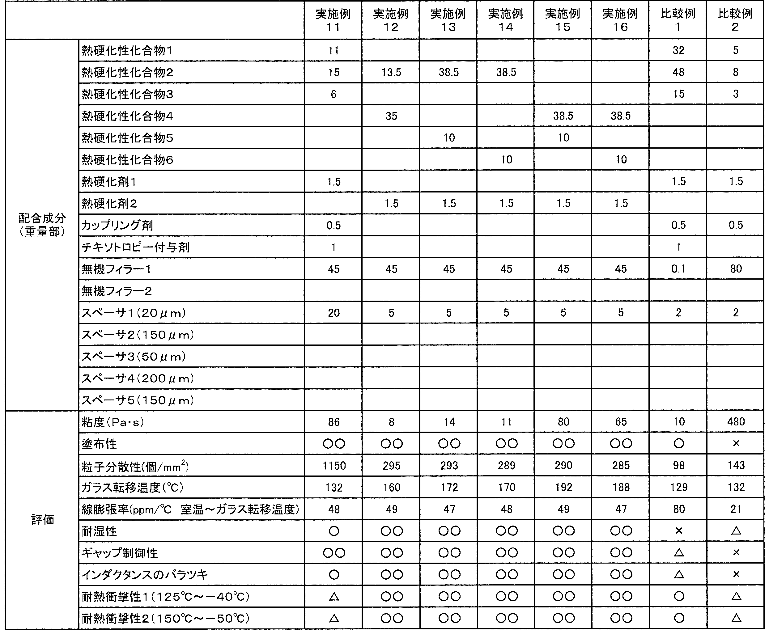
- Example 1 Preparation of Adhesive for Inductor According to the composition shown in Table 1, an adhesive composition was obtained by stirring and mixing each material other than the spacer with a rotation and revolution mixer. Spacer particles were blended in the obtained adhesive composition according to the composition shown in Table 1, and the mixture was stirred and mixed using a rotation and revolution mixer to produce an inductor adhesive.
- Examples 2 to 16 Comparative Examples 1 and 2
- An inductor adhesive, an inductor, and a sample for evaluating moisture resistance were obtained in the same manner as in Example 1 except that the types and amounts of the ingredients were changed as shown in Tables 1 and 2.
- Viscosity When the particle size of the spacer particles in the adhesive is 20 ⁇ m or less, the viscosity ( ⁇ 25) of the adhesive at 25 ° C. is measured using an E-type viscometer (“TVE22L” manufactured by Toki Sangyo Co., Ltd.). And measured under the conditions of 25 ° C. and 5 rpm.
- the viscosity ( ⁇ 25) at 25 ° C. of the adhesive is measured at 25 ° C. using a spiral viscometer (“PCU-02V” manufactured by Malcolm). The measurement was performed under the condition of 10 rpm.
- Coating property Evaluation of coating property was performed using a dispenser device ("SHOT MASTER300" manufactured by Musashi Engineering Co., Ltd.).
- the coating conditions are fixed by a precision nozzle (Musashi Engineering Co., Ltd., nozzle tip inner diameter 0.3 mm) and discharge conditions (temperature 25 ° C., discharge pressure 0.3 Mpa), and coated on a glass substrate, thereby improving the coating property. evaluated.
- the applicability was determined according to the following criteria.
- Tg glass transition temperature
- the adhesive was heated at 120 ° C. for 20 minutes, then heated at 170 ° C. for 15 minutes and cured to obtain a cured product.
- the tan ⁇ of the obtained cured product was measured using a viscoelasticity measuring device (manufactured by IT Measurement & Control Co., Ltd.) under conditions of a temperature rising rate of 10 ° C./min, a grip width of 20 mm and 5 Hz.
- the temperature at the peak of Tan ⁇ was defined as the glass transition temperature.
- Moisture resistance Measure the adhesion between the obtained sample for evaluating moisture resistance in an oven at 85 ° C. and 85% humidity for 24 hours and the sample obtained by leaving the sample for evaluating moisture resistance at room temperature. did. The moisture resistance was evaluated by measuring the die shear adhesive strength with a die shear tester “Dage series 4000” manufactured by Dage. The moisture resistance was determined according to the following criteria.
- Gap controllability In the obtained inductor, using a laser displacement meter (“KS-1100” manufactured by KEYENCE), the gap distance after curing and the gap distance variation 3 ⁇ ( ⁇ : standard deviation) are measured. did. The gap controllability was evaluated from the variation 3 ⁇ in the gap distance / the value X of the gap distance after curing. Gap controllability was determined according to the following criteria.
- Value X is less than 0.1 ⁇ : Value X is 0.1 or more and less than 0.2 ⁇ : Value X is 0.2 or more and less than 0.4 ⁇ : Value X is 0.4 or more
- CV value of inductance is less than 5%
- CV value of inductance is 5% or more and less than 10%
- ⁇ CV value of inductance is 10% or more and less than 15%
- CV value of inductance is 15% or more
- Thermal shock resistance 1 Long-term reliability
- the obtained inductor was left in an environment where 500 cycles of a temperature change of 30 minutes at a high temperature of 125 ° C. and 30 minutes at a low temperature of ⁇ 40 ° C. were given. Thereafter, the rate of change in inductance was measured.
- the characteristic change rate means a ratio of variation in inductance due to peeling on the adhesive surface due to thermal shock or a change in the distance between the gaps.
Landscapes
- Engineering & Computer Science (AREA)
- Power Engineering (AREA)
- Chemical & Material Sciences (AREA)
- Organic Chemistry (AREA)
- Inorganic Chemistry (AREA)
- Microelectronics & Electronic Packaging (AREA)
- Adhesives Or Adhesive Processes (AREA)
- Coils Or Transformers For Communication (AREA)
Abstract
Description
本発明に係るインダクタ用接着剤(以下、接着剤と略記することがある)は、インダクタに用いられる。本発明に係る接着剤は、熱硬化性化合物と、熱硬化剤と、無機フィラーと、スペーサ粒子とを含む。本発明に係る接着剤では、上記スペーサ粒子は、樹脂粒子又は有機無機ハイブリッド粒子である。本発明に係る接着剤では、上記スペーサ粒子の平均粒子径は20μm以上、200μm以下である。本発明に係る接着剤では、上記スペーサ粒子の粒子径のCV値は、10%以下である。本発明に係る接着剤100重量%中、上記無機フィラーの含有量は30重量%を超え、75重量%以下である。
ρ:スペーサ粒子の粒子径の標準偏差
Dn:スペーサ粒子の粒子径の平均値
上記接着剤に含まれる熱硬化性化合物は特に限定されない。上記熱硬化性化合物は、加熱により硬化可能な化合物である。上記熱硬化性化合物は、1種のみが用いられてもよく、2種以上が併用されてもよい。
上記熱硬化剤は、上記熱硬化性化合物を熱硬化させる。上記熱硬化剤としては、イミダゾール硬化剤、フェノール硬化剤、チオール硬化剤、アミン硬化剤、酸無水物硬化剤、熱カチオン開始剤及び熱ラジカル発生剤等がある。上記熱硬化剤は、1種のみが用いられてもよく、2種以上が併用されてもよい。
スペーサ粒子としては、樹脂粒子、金属粒子を除く無機粒子、有機無機ハイブリッド粒子及び金属粒子等が挙げられる。本発明では、上記スペーサ粒子は、樹脂粒子又は有機無機ハイブリッド粒子である。上記スペーサ粒子は、コアと、該コアの表面上に配置されたシェルとを備えるコアシェル粒子であってもよい。上記コアが有機コアであってもよい。上記シェルが無機シェルであってもよい。接着部に応力が加わったときに、応力を緩和でき、接着性を高く維持する観点からは、金属粒子を除くスペーサ粒子が好ましく、樹脂粒子、金属粒子を除く無機粒子又は有機無機ハイブリッド粒子がより好ましい。本発明の効果により一層優れることから、本発明では、樹脂粒子又は有機無機ハイブリッド粒子が用いられる。
F:スペーサ粒子が10%圧縮変形したときの荷重値(N)
S:スペーサ粒子が10%圧縮変形したときの圧縮変位(mm)
R:スペーサ粒子の半径(mm)
上記無機フィラーの材料としては、シリカ、タルク、クレイ、マイカ、ハイドロタルサイト、アルミナ、酸化マグネシウム、水酸化アルミニウム、窒化アルミニウム及び窒化ホウ素等が挙げられる。
上記接着剤は、光硬化性成分を含んでいてもよく、光硬化性化合物と、光重合開始剤とを含んでいてもよい。
本発明に係るインダクタは、フェライトコアと、上記フェライトコアを接着している接着部とを備える。本発明に係るインダクタでは、上接着部の材料が、上述したインダクタ用接着剤である。上記接着部は、上記インダクタ用接着剤の硬化物である。上記接着部は、上記インダクタ用接着剤を硬化させることにより形成される。
熱硬化性化合物2:ビスフェノールF型エポキシ化合物、DIC製「EXA-830CRP」
熱硬化性化合物3:ナフタレン型エポキシ化合物、DIC社製「HP-4032D」
熱硬化性化合物4:ビスフェノールA型エポキシ化合物、DIC製「EXA-850CRP」
熱硬化性化合物5:ナフタレン型エポキシ化合物、DIC社製「HP-4710」
熱硬化性化合物6:フルオレン型エポキシ化合物、大阪ガスケミカル社製「OGSOL PG-100」
熱硬化剤2:イミダゾール硬化促進剤、四国化成工業社製「2MZA-PW」
無機フィラー2:シリカ、平均粒子径3.8μm、龍森社製「EXR-4」
スペーサ2:平均粒子径150μm、CV値7%、10%K値2000N/mm2、積水化学工業社製「SP-L150」、樹脂粒子
スペーサ3:平均粒子径50μm、CV値5%、10%K値3800N/mm2、積水化学工業社製「SP-250」、樹脂粒子
スペーサ4:平均粒子径200μm、CV値7%、10%K値3900N/mm2、積水化学工業社製「GS-L200」、樹脂粒子
(1)インダクタ用接着剤の調製
表1の組成に従って、スペーサ以外の各材料を、自転公転ミキサーにて撹拌混合することで、接着剤組成物を得た。得られた接着剤組成物に、スペーサ粒子を表1の組成に従って配合し、自転公転ミキサーを用いて撹拌混合することでインダクタ用接着剤を作製した。
得られたインダクタ用接着剤を10mLシリンジ(武蔵エンジニアリング社製)に充填し、シリンジの先端に精密ノズル(武蔵エンジニアリング社製、ノズル先端内径:スペーサ粒子径が100μm未満の場合、0.3mm、スペーサの粒子径が100μm以上の場合 0.6mm)を取り付け、ディスペンサ装置(武蔵エンジニアリング社製「SHOT MASTER300」)を用いて、I型コアに塗布し、E型コアと貼り合せた後、リフロー炉にて硬化させ、インダクタを得た。
得られたインダクタ用接着剤を10mLシリンジ(武蔵エンジニアリング社製)に充填し、シリンジの先端に精密ノズル(武蔵エンジニアリング社製、ノズル先端内径0.3mm)を取り付け、ディスペンサ装置(武蔵エンジニアリング社製「SHOT MASTER300」)を用いて、縦3mm横3mm厚み0.3mmのインダクタと同質のフェライト片5個と縦20mm横20mm厚み0.3mmのインダクタと同質のフェライト片1個とを貼り合わせた後、リフロー炉にて硬化させ、耐湿性評価用サンプルを得た。
配合成分の種類及び配合量を表1,2に示すように変更したこと以外は実施例1と同様にして、インダクタ用接着剤、インダクタ、及び耐湿性評価用サンプルを得た。
(1)粘度
接着剤中のスペーサ粒子の粒子径が20μm以下である場合には、接着剤の25℃での粘度(η25)を、E型粘度計(東機産業社製「TVE22L」)を用いて、25℃及び5rpmの条件で測定した。
塗布性の評価は、ディスペンサ装置(武蔵エンジニアリング社製「SHOT MASTER300」)を用いて行った。塗布条件は、精密ノズル(武蔵エンジニアリング社製、ノズル先端内径0.3mm)、吐出条件(温度25℃、吐出圧0.3Mpa)にて固定し、ガラス基板上に塗布することで、塗布性を評価した。塗布性を下記の基準で判定した。
○○:かすれやダレが無く塗布できた
○:わずかにかすれやダレが生じた
△:塗布切れはないが大きなかすれやダレが生じた
×:塗布切れが生じるか、又は全く塗布できなかった
接着剤30mgを第1のスライドガラスに載せ、接着剤上に第2のスライドガラスを載せた後、上記第2のスライドガラス上に50gの重りを載せて、20分間放置した。放置後に、光学顕微鏡を用いて、平面視にて、1mm2当たりのスペーサ粒子の個数を測定した。
接着剤を120℃で20分間加熱した後、170℃で15分間加熱し、硬化させて硬化物を得た。得られた硬化物のtanδを、粘弾性測定機(アイティー計測制御社製)を用いて、昇温速度10℃/分、及びつかみ幅20mm及び5Hzの条件で測定した。Tanδのピーク時の温度をガラス転移温度とした。
接着剤を120℃で20分間加熱した後、170℃で15分間加熱し、硬化させて硬化物を得た。得られた硬化物の線膨張率をTMA/SS6000(Seiko Instruments社製)を用いて、昇温速度5℃/minで室温(25℃)から250℃まで加熱する条件で測定した。
得られた耐湿性評価用サンプルを85℃、湿度85%のオーブンに24時間放置したサンプルと、得られた耐湿性評価用サンプルを常温で放置したサンプルとの接着力を測定した。Dage社製のダイシェアテスター「Dage series 4000」にてダイシェア接着力を測定することで、耐湿性を評価した。耐湿性を下記の基準で判定した。
○○:高温高湿下で放置したサンプルの接着力が、常温で放置したサンプルの接着力の90%以上
○:高温高湿下で放置したサンプルの接着力が、常温で放置したサンプルの接着力の80%以上90%未満
△:高温高湿下で放置したサンプルの接着力が、常温で放置したサンプルの接着力の70%以上80%未満
×:高温高湿下で放置したサンプルの接着力が、常温で放置したサンプルの接着力の70%未満
得られたインダクタにおいて、レーザー変位計(KEYENCE社製「KS-1100」)を用いて、硬化後のギャップ間距離及びギャップ間距離のバラツキ3σ(σ;標準偏差)を測定した。ギャップ間距離のバラツキ3σ/硬化後のギャップ間距離の値Xから、ギャップ制御性を評価した。ギャップ制御性を下記の基準で判定した。
○○:値Xが0.1未満
○:値Xが0.1以上0.2未満
△:値Xが0.2以上0.4未満
×:値Xが0.4以上
得られたインダクタ20個のインダクタンスを測定し、バラツキを評価した。インダクタンスのバラツキを下記の基準で判定した。
○○:インダクタンスのCV値が5%未満
○:インダクタンスのCV値が5%以上10%未満
△:インダクタンスのCV値が10%以上15%未満
×:インダクタンスのCV値が15%以上
得られたインダクタを高温125℃で30分、低温-40℃で30分の温度変化を500サイクル与える環境下に放置した。その後、インダクタンスの変化率を測定した。特性変化率は、熱衝撃により接着面に剥離が生じたり、ギャップ間距離に変化が生じたことによるインダクタンスのバラツキ割合を意味する。
○○:インダクタンスの初期値からの変化率が10%未満
○:インダクタンスの初期値からの変化率が10%以上20%未満
△:インダクタンスの初期値からの変化率が20%以上30%未満
×:インダクタンスの初期値からの変化率が30%以上
得られたインダクタを高温150℃で30分、低温-50℃で30分の温度変化を500サイクル与える環境下に放置した。その後、インダクタンスの変化率を測定した。
○○:インダクタンスの初期値からの変化率が10%未満
○:インダクタンスの初期値からの変化率が10%以上20%未満
△:インダクタンスの初期値からの変化率が20%以上30%未満
×:インダクタンスの初期値からの変化率が30%以上

11…フェライトコア(E型)
12…フェライトコア(I型)
13…接着部
Claims (11)
- インダクタに用いられるインダクタ用接着剤であり、
熱硬化性化合物と、熱硬化剤と、無機フィラーと、スペーサ粒子とを含み、
前記スペーサ粒子が、樹脂粒子又は有機無機ハイブリッド粒子であり、
前記スペーサ粒子の平均粒子径が20μm以上、200μm以下であり、
前記スペーサ粒子の粒子径のCV値が、10%以下であり、
前記接着剤100重量%中、前記無機フィラーの含有量が30重量%を超え、75重量%以下である、インダクタ用接着剤。 - 前記接着剤を120℃で20分間加熱した後、170℃で15分間加熱して硬化物を得たときに、得られる硬化物のガラス転移点温度が120℃以上、210℃以下である、請求項1に記載のインダクタ用接着剤。
- 前記接着剤30mgを第1のスライドガラスに載せ、前記接着剤上に第2のスライドガラスを載せた後、前記第2のスライドガラス上に50gの重りを載せて、20分間放置したときに、平面視にて、前記スペーサ粒子の個数が2個/mm2以上、1000個/mm2以下である、請求項1又は2に記載に記載のインダクタ用接着剤。
- 前記熱硬化性化合物100重量部に対して、前記熱硬化剤の含有量が0.01重量部以上、10重量部以下である、請求項1~3のいずれか1項に記載のインダクタ用接着剤。
- 前記接着剤の25℃での粘度が10Pa・s以上、150Pa・s以下である、請求項1~4のいずれか1項に記載のインダクタ用接着剤。
- 前記接着剤100重量%中、前記スペーサ粒子の含有量が1重量%以上、15重量%以下である、請求項1~5のいずれか1項に記載のインダクタ用接着剤。
- 前記接着剤100重量%中の前記無機フィラーの含有量の、前記接着剤100重量%中の前記スペーサ粒子の含有量に対する比が3以上、60以下である、請求項1~6のいずれか1項に記載のインダクタ用接着剤。
- 前記無機フィラーの平均粒子径の、前記スペーサ粒子の平均粒子径に対する比が0.00005以上、0.1以下である、請求項1~7のいずれか1項に記載のインダクタ用接着剤。
- 前記スペーサ粒子の10%K値が980N/mm2以上、4900N/mm2以下である、請求項1~8のいずれか1項に記載のインダクタ用接着剤。
- インダクタにおけるフェライトコアの接着に用いられる、請求項1~9のいずれか1項に記載のインダクタ用接着剤。
- フェライトコアと、
前記フェライトコアを接着している接着部とを備え、
前記接着部の材料が、請求項1~10のいずれか1項に記載のインダクタ用接着剤である、インダクタ。
Priority Applications (3)
| Application Number | Priority Date | Filing Date | Title |
|---|---|---|---|
| CN201780004012.3A CN108352243B (zh) | 2016-03-30 | 2017-03-28 | 电感器用粘接剂及电感器 |
| JP2017518179A JP6232167B1 (ja) | 2016-03-30 | 2017-03-28 | インダクタ用接着剤及びインダクタ |
| KR1020187010191A KR102195623B1 (ko) | 2016-03-30 | 2017-03-28 | 인덕터용 접착제 및 인덕터 |
Applications Claiming Priority (2)
| Application Number | Priority Date | Filing Date | Title |
|---|---|---|---|
| JP2016-068283 | 2016-03-30 | ||
| JP2016068283 | 2016-03-30 |
Publications (1)
| Publication Number | Publication Date |
|---|---|
| WO2017170492A1 true WO2017170492A1 (ja) | 2017-10-05 |
Family
ID=59965651
Family Applications (1)
| Application Number | Title | Priority Date | Filing Date |
|---|---|---|---|
| PCT/JP2017/012547 Ceased WO2017170492A1 (ja) | 2016-03-30 | 2017-03-28 | インダクタ用接着剤及びインダクタ |
Country Status (5)
| Country | Link |
|---|---|
| JP (2) | JP6232167B1 (ja) |
| KR (1) | KR102195623B1 (ja) |
| CN (1) | CN108352243B (ja) |
| TW (1) | TWI630252B (ja) |
| WO (1) | WO2017170492A1 (ja) |
Cited By (2)
| Publication number | Priority date | Publication date | Assignee | Title |
|---|---|---|---|---|
| JP2020097215A (ja) * | 2017-10-24 | 2020-06-25 | Dic株式会社 | ラミネート方法 |
| CN115547633A (zh) * | 2021-06-14 | 2022-12-30 | Tdk株式会社 | 线圈装置 |
Families Citing this family (5)
| Publication number | Priority date | Publication date | Assignee | Title |
|---|---|---|---|---|
| JP6730397B2 (ja) * | 2018-09-28 | 2020-07-29 | 太陽誘電株式会社 | コイル部品及び電子機器 |
| CN111477442A (zh) * | 2019-01-24 | 2020-07-31 | 昆山玛冀电子有限公司 | 一种改善模压电感烘烤后开裂现象的方法 |
| KR102692022B1 (ko) | 2020-02-28 | 2024-08-06 | 엘지이노텍 주식회사 | 자성 코어 및 이를 포함하는 자성 소자 |
| CN115910550A (zh) * | 2022-11-18 | 2023-04-04 | 厦门艾申迪电子有限公司 | 新型电感器 |
| CN117866571A (zh) * | 2023-12-22 | 2024-04-12 | 上海回天新材料有限公司 | 一种磁元件粘结用环氧树脂胶粘剂及其制备方法 |
Citations (7)
| Publication number | Priority date | Publication date | Assignee | Title |
|---|---|---|---|---|
| JPS63164409A (ja) * | 1986-12-26 | 1988-07-07 | Matsushita Electric Ind Co Ltd | 変成器 |
| JPH11273958A (ja) * | 1998-03-25 | 1999-10-08 | Kawaguchiko Seimitsu Kk | 表面実装型トランスコア |
| JP2000269039A (ja) * | 1999-03-16 | 2000-09-29 | Tdk Corp | 低背型表面実装コイル部品 |
| JP2004235462A (ja) * | 2003-01-30 | 2004-08-19 | Neomax Co Ltd | インダクタ |
| WO2009011383A1 (ja) * | 2007-07-19 | 2009-01-22 | Sekisui Chemical Co., Ltd. | 電子部品用接着剤 |
| WO2009014115A1 (ja) * | 2007-07-25 | 2009-01-29 | Sekisui Chemical Co., Ltd. | 電子部品用接着剤、半導体チップの積層方法及び半導体装置 |
| JP2013004932A (ja) * | 2011-06-21 | 2013-01-07 | Sumitomo Electric Ind Ltd | リアクトル、およびその製造方法 |
Family Cites Families (10)
| Publication number | Priority date | Publication date | Assignee | Title |
|---|---|---|---|---|
| CN101578345A (zh) * | 2007-01-12 | 2009-11-11 | 积水化学工业株式会社 | 电子部件用粘合剂 |
| TW200831627A (en) * | 2007-01-12 | 2008-08-01 | Sekisui Chemical Co Ltd | Adhesive for electronic components |
| JP5118956B2 (ja) * | 2007-12-26 | 2013-01-16 | 積水化学工業株式会社 | 電子部品用接着剤 |
| JP2010114333A (ja) * | 2008-11-10 | 2010-05-20 | Daido Electronics Co Ltd | ボンド磁石の製造方法 |
| TWI481685B (zh) * | 2009-01-29 | 2015-04-21 | 積水化學工業股份有限公司 | Adhesive for electronic parts |
| TWI489565B (zh) | 2009-03-10 | 2015-06-21 | 積水化學工業股份有限公司 | Semiconductor wafer laminated body manufacturing method and semiconductor device |
| JP2011198953A (ja) * | 2010-03-18 | 2011-10-06 | Sekisui Chem Co Ltd | 電子部品積層体の製造方法 |
| JP5721416B2 (ja) * | 2010-12-13 | 2015-05-20 | 積水化学工業株式会社 | 熱伝導性接着剤 |
| KR20140132451A (ko) * | 2013-05-08 | 2014-11-18 | 금호석유화학 주식회사 | 스페이서를 포함하는 액정표시장치용 접착제 조성물, 이를 제조하는 방법 및 사용하는 방법 |
| FR3012818B1 (fr) * | 2013-11-04 | 2015-11-20 | Bostik Sa | Composition de colle bicomposante a base de polyurethane |
-
2017
- 2017-03-28 KR KR1020187010191A patent/KR102195623B1/ko active Active
- 2017-03-28 WO PCT/JP2017/012547 patent/WO2017170492A1/ja not_active Ceased
- 2017-03-28 CN CN201780004012.3A patent/CN108352243B/zh active Active
- 2017-03-28 JP JP2017518179A patent/JP6232167B1/ja active Active
- 2017-03-30 TW TW106110719A patent/TWI630252B/zh active
- 2017-10-10 JP JP2017196583A patent/JP6856489B2/ja active Active
Patent Citations (7)
| Publication number | Priority date | Publication date | Assignee | Title |
|---|---|---|---|---|
| JPS63164409A (ja) * | 1986-12-26 | 1988-07-07 | Matsushita Electric Ind Co Ltd | 変成器 |
| JPH11273958A (ja) * | 1998-03-25 | 1999-10-08 | Kawaguchiko Seimitsu Kk | 表面実装型トランスコア |
| JP2000269039A (ja) * | 1999-03-16 | 2000-09-29 | Tdk Corp | 低背型表面実装コイル部品 |
| JP2004235462A (ja) * | 2003-01-30 | 2004-08-19 | Neomax Co Ltd | インダクタ |
| WO2009011383A1 (ja) * | 2007-07-19 | 2009-01-22 | Sekisui Chemical Co., Ltd. | 電子部品用接着剤 |
| WO2009014115A1 (ja) * | 2007-07-25 | 2009-01-29 | Sekisui Chemical Co., Ltd. | 電子部品用接着剤、半導体チップの積層方法及び半導体装置 |
| JP2013004932A (ja) * | 2011-06-21 | 2013-01-07 | Sumitomo Electric Ind Ltd | リアクトル、およびその製造方法 |
Cited By (3)
| Publication number | Priority date | Publication date | Assignee | Title |
|---|---|---|---|---|
| JP2020097215A (ja) * | 2017-10-24 | 2020-06-25 | Dic株式会社 | ラミネート方法 |
| CN115547633A (zh) * | 2021-06-14 | 2022-12-30 | Tdk株式会社 | 线圈装置 |
| CN115547633B (zh) * | 2021-06-14 | 2026-04-24 | Tdk株式会社 | 线圈装置 |
Also Published As
| Publication number | Publication date |
|---|---|
| TW201802215A (zh) | 2018-01-16 |
| KR102195623B1 (ko) | 2020-12-28 |
| KR20180124009A (ko) | 2018-11-20 |
| JPWO2017170492A1 (ja) | 2018-04-05 |
| TWI630252B (zh) | 2018-07-21 |
| CN108352243B (zh) | 2020-12-04 |
| CN108352243A (zh) | 2018-07-31 |
| JP6232167B1 (ja) | 2017-11-15 |
| JP2018031019A (ja) | 2018-03-01 |
| JP6856489B2 (ja) | 2021-04-07 |
Similar Documents
| Publication | Publication Date | Title |
|---|---|---|
| JP6232167B1 (ja) | インダクタ用接着剤及びインダクタ | |
| JP2022122992A (ja) | 樹脂組成物及びインダクタ | |
| US20080295959A1 (en) | Thermally Conductive Adhesive Composition and Adhesion Method | |
| JP2011526309A (ja) | 銀被覆フレーク状材料で充填された伝導性硬化性組成物およびダイ取付け用途 | |
| JP5941640B2 (ja) | 複合磁性体 | |
| EP4495955A2 (en) | Method for forming uv-curable conductive compositions and a composition thus formed | |
| KR20130028691A (ko) | 열전도성 시트 및 그의 제조 방법 | |
| CN102666722A (zh) | 单组分型液态环氧树脂组合物及使用其的粘合方法 | |
| JP6290553B2 (ja) | 複合磁性体 | |
| KR20130028690A (ko) | 열전도성 시트 및 그의 제조 방법 | |
| US10961420B2 (en) | Composition for bonding, optical adhesive, and adhesive for pressure sensor | |
| JP5946688B2 (ja) | 後硬化テープ及び接合部材の接合方法 | |
| JP2018188628A (ja) | 熱硬化性材料 | |
| JP6795409B2 (ja) | 硬化性材料、硬化性材料の製造方法及び積層体 | |
| JP5074982B2 (ja) | エポキシ樹脂硬化促進用マイクロカプセル及びエポキシ樹脂硬化促進用マイクロカプセルの製造方法 | |
| JP7149956B2 (ja) | ラジカル硬化型接着組成物、接着剤 | |
| JP2018082167A (ja) | 硬化性材料及び積層体 | |
| JP6840794B2 (ja) | 熱硬化性接着シートおよびその製造方法 | |
| JP2018082166A (ja) | 硬化性材料及び積層体 | |
| JPWO2018008332A1 (ja) | ラジカル硬化型接着組成物、接着剤 | |
| WO2025220687A1 (ja) | 組成物、硬化物、及び硬化物を備える物品 | |
| JP6276531B2 (ja) | 複合磁性体 | |
| JP2013104051A (ja) | 後硬化テープ及び接合部材の接合方法 | |
| WO2022131318A1 (ja) | 接着性粒子、接着剤及び調光積層体 |
Legal Events
| Date | Code | Title | Description |
|---|---|---|---|
| ENP | Entry into the national phase |
Ref document number: 2017518179 Country of ref document: JP Kind code of ref document: A |
|
| ENP | Entry into the national phase |
Ref document number: 20187010191 Country of ref document: KR Kind code of ref document: A |
|
| NENP | Non-entry into the national phase |
Ref country code: DE |
|
| 121 | Ep: the epo has been informed by wipo that ep was designated in this application |
Ref document number: 17775029 Country of ref document: EP Kind code of ref document: A1 |
|
| 122 | Ep: pct application non-entry in european phase |
Ref document number: 17775029 Country of ref document: EP Kind code of ref document: A1 |