WO2017170290A1 - 電動アクチュエータ - Google Patents
電動アクチュエータ Download PDFInfo
- Publication number
- WO2017170290A1 WO2017170290A1 PCT/JP2017/012192 JP2017012192W WO2017170290A1 WO 2017170290 A1 WO2017170290 A1 WO 2017170290A1 JP 2017012192 W JP2017012192 W JP 2017012192W WO 2017170290 A1 WO2017170290 A1 WO 2017170290A1
- Authority
- WO
- WIPO (PCT)
- Prior art keywords
- gear
- lock
- lock member
- electric actuator
- drive unit
- Prior art date
- Legal status (The legal status is an assumption and is not a legal conclusion. Google has not performed a legal analysis and makes no representation as to the accuracy of the status listed.)
- Ceased
Links
Images









Classifications
-
- F—MECHANICAL ENGINEERING; LIGHTING; HEATING; WEAPONS; BLASTING
- F16—ENGINEERING ELEMENTS AND UNITS; GENERAL MEASURES FOR PRODUCING AND MAINTAINING EFFECTIVE FUNCTIONING OF MACHINES OR INSTALLATIONS; THERMAL INSULATION IN GENERAL
- F16H—GEARING
- F16H25/00—Gearings comprising primarily only cams, cam-followers and screw-and-nut mechanisms
- F16H25/18—Gearings comprising primarily only cams, cam-followers and screw-and-nut mechanisms for conveying or interconverting oscillating or reciprocating motions
- F16H25/20—Screw mechanisms
- F16H25/24—Elements essential to such mechanisms, e.g. screws, nuts
- F16H25/2454—Brakes; Rotational locks
-
- F—MECHANICAL ENGINEERING; LIGHTING; HEATING; WEAPONS; BLASTING
- F16—ENGINEERING ELEMENTS AND UNITS; GENERAL MEASURES FOR PRODUCING AND MAINTAINING EFFECTIVE FUNCTIONING OF MACHINES OR INSTALLATIONS; THERMAL INSULATION IN GENERAL
- F16H—GEARING
- F16H25/00—Gearings comprising primarily only cams, cam-followers and screw-and-nut mechanisms
- F16H25/18—Gearings comprising primarily only cams, cam-followers and screw-and-nut mechanisms for conveying or interconverting oscillating or reciprocating motions
- F16H25/20—Screw mechanisms
-
- F—MECHANICAL ENGINEERING; LIGHTING; HEATING; WEAPONS; BLASTING
- F16—ENGINEERING ELEMENTS AND UNITS; GENERAL MEASURES FOR PRODUCING AND MAINTAINING EFFECTIVE FUNCTIONING OF MACHINES OR INSTALLATIONS; THERMAL INSULATION IN GENERAL
- F16H—GEARING
- F16H25/00—Gearings comprising primarily only cams, cam-followers and screw-and-nut mechanisms
- F16H25/18—Gearings comprising primarily only cams, cam-followers and screw-and-nut mechanisms for conveying or interconverting oscillating or reciprocating motions
- F16H25/20—Screw mechanisms
- F16H25/22—Screw mechanisms with balls, rollers, or similar members between the co-operating parts; Elements essential to the use of such members
-
- H—ELECTRICITY
- H02—GENERATION; CONVERSION OR DISTRIBUTION OF ELECTRIC POWER
- H02K—DYNAMO-ELECTRIC MACHINES
- H02K7/00—Arrangements for handling mechanical energy structurally associated with dynamo-electric machines, e.g. structural association with mechanical driving motors or auxiliary dynamo-electric machines
- H02K7/06—Means for converting reciprocating motion into rotary motion or vice versa
-
- H—ELECTRICITY
- H02—GENERATION; CONVERSION OR DISTRIBUTION OF ELECTRIC POWER
- H02K—DYNAMO-ELECTRIC MACHINES
- H02K7/00—Arrangements for handling mechanical energy structurally associated with dynamo-electric machines, e.g. structural association with mechanical driving motors or auxiliary dynamo-electric machines
- H02K7/10—Structural association with clutches, brakes, gears, pulleys or mechanical starters
- H02K7/116—Structural association with clutches, brakes, gears, pulleys or mechanical starters with gears
-
- F—MECHANICAL ENGINEERING; LIGHTING; HEATING; WEAPONS; BLASTING
- F16—ENGINEERING ELEMENTS AND UNITS; GENERAL MEASURES FOR PRODUCING AND MAINTAINING EFFECTIVE FUNCTIONING OF MACHINES OR INSTALLATIONS; THERMAL INSULATION IN GENERAL
- F16H—GEARING
- F16H25/00—Gearings comprising primarily only cams, cam-followers and screw-and-nut mechanisms
- F16H25/18—Gearings comprising primarily only cams, cam-followers and screw-and-nut mechanisms for conveying or interconverting oscillating or reciprocating motions
- F16H25/20—Screw mechanisms
- F16H2025/2062—Arrangements for driving the actuator
- F16H2025/2081—Parallel arrangement of drive motor to screw axis
-
- F—MECHANICAL ENGINEERING; LIGHTING; HEATING; WEAPONS; BLASTING
- F16—ENGINEERING ELEMENTS AND UNITS; GENERAL MEASURES FOR PRODUCING AND MAINTAINING EFFECTIVE FUNCTIONING OF MACHINES OR INSTALLATIONS; THERMAL INSULATION IN GENERAL
- F16H—GEARING
- F16H25/00—Gearings comprising primarily only cams, cam-followers and screw-and-nut mechanisms
- F16H25/18—Gearings comprising primarily only cams, cam-followers and screw-and-nut mechanisms for conveying or interconverting oscillating or reciprocating motions
- F16H25/20—Screw mechanisms
- F16H2025/2062—Arrangements for driving the actuator
- F16H2025/2087—Arrangements for driving the actuator using planetary gears
-
- F—MECHANICAL ENGINEERING; LIGHTING; HEATING; WEAPONS; BLASTING
- F16—ENGINEERING ELEMENTS AND UNITS; GENERAL MEASURES FOR PRODUCING AND MAINTAINING EFFECTIVE FUNCTIONING OF MACHINES OR INSTALLATIONS; THERMAL INSULATION IN GENERAL
- F16H—GEARING
- F16H25/00—Gearings comprising primarily only cams, cam-followers and screw-and-nut mechanisms
- F16H25/18—Gearings comprising primarily only cams, cam-followers and screw-and-nut mechanisms for conveying or interconverting oscillating or reciprocating motions
- F16H25/20—Screw mechanisms
- F16H25/22—Screw mechanisms with balls, rollers, or similar members between the co-operating parts; Elements essential to the use of such members
- F16H25/2204—Screw mechanisms with balls, rollers, or similar members between the co-operating parts; Elements essential to the use of such members with balls
Definitions
- the present invention relates to an electric actuator.
- the ball screw mechanism has very good driving force transmission efficiency to the operation target device, but the ball screw shaft may move in the axial direction when an external force is input to the ball screw from the operation target device side. is there.
- a device having a lock mechanism for preventing the ball screw from being driven by a reverse input from the operation target device side has been proposed.
- a shaft 300 is provided as a lock member that can be engaged and disengaged with respect to a gear 40 that transmits a driving force from the electric motor 100 to the ball screw 200. Is prevented from driving the ball screw 200.
- the shaft 300 is disposed at a position far from the ball screw 200 in the radial direction with respect to the rotation center of the gear 400. There is a problem that the distance becomes longer, the electric actuator becomes larger, and the space required for installation becomes larger.
- an object of the present invention is to provide an electric actuator that can be miniaturized.
- the present invention includes a drive unit, a motion conversion mechanism unit that converts rotational motion from the drive unit into linear motion in an axial direction parallel to the output shaft of the drive unit,
- An electric actuator comprising a driving force transmission unit having a transmission gear mechanism for transmitting a driving force from the driving unit to the motion conversion mechanism unit, and a lock mechanism unit for preventing the motion conversion mechanism unit from being driven.
- the lock mechanism unit is disposed on the side opposite to the drive unit with respect to the first gear and on the motion conversion mechanism unit side with respect to the rotation center line of the first gear, so that the lock mechanism unit is arranged. Can be arranged close to the motion conversion mechanism without considering interference with the drive. As a result, the electric actuator can be reduced in size.
- the present invention includes a drive unit and a motion conversion mechanism unit that converts rotational motion from the drive unit into linear motion in an axial direction parallel to the output shaft of the drive unit.
- an electric actuator including a driving force transmission unit having a transmission gear mechanism for transmitting a driving force from the driving unit to the motion conversion mechanism unit, and a lock mechanism unit for preventing the motion conversion mechanism unit from being driven.
- the first gear disposed on the drive unit side and the second gear disposed on the motion conversion mechanism unit side, and the lock mechanism unit is a motion conversion mechanism with respect to the first gear than the rotation center line thereof.
- the lock mechanism portion is arranged closer to the motion conversion mechanism portion by engaging the first gear with the motion conversion mechanism portion side than the rotation center line. This makes it easier to reduce the size of the electric actuator.
- the lock mechanism includes a lock member that can be engaged with and disengaged from the engagement hole, a lock state in which the rotation motion of the rotary motor is converted into a linear motion and the lock member is engaged with the engagement hole, and a lock that is unlocked.
- a sliding screw device that is driven so as to be in at least one of a released state and a released state can be provided.
- the actuator case has a rotation restricting portion that restricts the rotation of the linearly moving member of the sliding screw device, it is not necessary to separately provide a rotation restricting member, which is advantageous for downsizing.
- one of a slide screw nut and a slide screw shaft constituting the slide screw device is fixed to the lock member, the other is fixed to the output shaft of the rotary motor, and the tip end side of the lock member is formed in a flat plate shape
- the actuator case can have a function as a rotation restricting portion. That is, in this case, since the distal end side of the locking member formed in a flat plate shape is inserted into the through hole formed in a rectangular cross section, the rotation of the locking member in the through hole is restricted, The rotation of the fixed sliding screw nut or the sliding screw shaft is restricted, and linear motion is possible.
- the front end portion side of the lock member is arranged coaxially with the output shaft of the rotary motor.
- the lock mechanism has a spring that urges the lock member in a locked state, and the rotary motor unlocks the lock member against the urging force of the spring when the drive unit is driven. You may make it drive so that it may switch to a state. In this case, the locked state can be maintained by the biasing force of the spring without supplying power to the rotary motor.
- the rotation of the drive unit may be transmitted by being decelerated from the first gear to the second gear.
- the rotational torque is increased and transmitted from the first gear to the second gear. Therefore, as described above, by using the first gear with a small rotational torque as the mating gear with which the lock mechanism is engaged, the lock mechanism is engaged with the lock mechanism during engagement rather than with the second gear with a large rotational torque. Such a load can be reduced.
- the engagement partner of the lock mechanism portion is the first gear having a high rotational speed, it can be positioned more finely than in the case of the second gear after deceleration, and the motion conversion mechanism portion can be The position accuracy for stopping is improved.
- the electric actuator may include a shaft case that houses a shaft portion that linearly moves the motion conversion mechanism portion, and the shaft case may have a holder portion that holds the lock mechanism portion.
- the shaft mechanism can be reduced in size by arranging the lock mechanism portion close to the motion conversion mechanism portion.
- the drive unit is driven to swing the gear in one circumferential direction and the opposite direction, and the circumferential phase of the engagement hole with respect to the lock member. You may make it match.
- the lock member is engaged with the engagement hole.
- the phase can be adjusted with a smaller amount of rotation than when the gears are rotated in one direction to adjust the phase of the engagement holes. For this reason, there is little influence on the stop position of the electric actuator in the linear motion direction, and the position can be held with high accuracy.
- the electric actuator includes a lock sensor that detects an advancing / retreating position of the lock member, and the lock sensor moves the lock member forward while swinging the gear, and when the tip portion starts to be inserted into at least the engagement hole.
- the forward movement of the lock member may be stopped after a predetermined time has elapsed since the position of the lock member is detected and the lock sensor detects the position of the lock member.
- the tip of the lock member starts to be inserted into at least the engagement hole
- the position of the lock member is detected by the lock sensor, and the advancement of the lock member is stopped after a predetermined time has elapsed from the detected timing.
- the lock member can be reliably inserted into the engagement hole. That is, the timing of stopping the advancement of the lock member is counted at least after a predetermined time has elapsed since the lock member started to be inserted into the engagement hole, so that the lock member is not sufficiently inserted into the engagement hole. It can be managed so as not to become excessive or excessive.
- the swinging width of the gear be set to half the pitch between the engagement holes in one circumferential direction and the opposite direction.
- the gear when the lock member is retracted and separated from the engagement hole, the gear may be swung in one circumferential direction and the opposite direction by driving the drive unit.
- the gear is oscillated to prevent the lock member and the gear (the engagement surface of the engagement hole) from being caught, and the lock member is engaged. Since it becomes easy to remove from the joint hole, the locked state can be reliably released.
- an electric actuator suitable for miniaturization can be provided.
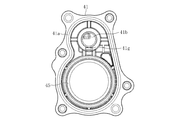
- FIG. 2 is a cross-sectional view taken along the line AA in FIG. It is a disassembled perspective view of a deceleration mechanism part. It is a disassembled perspective view of a shaft case and the lock mechanism part attached to this.
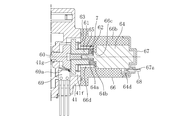
- FIG. 2 is a cross-sectional view taken along line BB in FIG. It is the front view which looked at the bearing case from the left side in FIG.
- FIG. 2 is a cross-sectional view taken along the line CC in FIG.
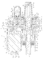
- FIG. 1 is a longitudinal sectional view showing an assembled state of an electric actuator according to an embodiment of the present invention
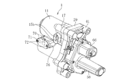
- FIG. 2 is an external perspective view showing the assembled state of the electric actuator
- FIG. 3 is an exploded perspective view of the electric actuator. It is.
- the electric actuator 1 of the present embodiment includes a drive unit 2 that generates a driving force, a motion conversion mechanism unit 3 that converts a rotational motion from the drive unit 2 into a linear motion, and a drive unit 2.
- a driving force transmission unit 4 that transmits a driving force to the motion conversion mechanism unit 3; a motion conversion mechanism support unit 5 that supports the motion conversion mechanism unit 3; an operation unit 6 that outputs the motion of the motion conversion mechanism unit 3;
- the lock mechanism unit 7 that prevents the conversion mechanism unit 3 from being driven is mainly configured.
- the drive unit 2 includes a motor unit 8 and a speed reduction mechanism unit 9.
- Each part constituting the electric actuator 1 has a case, and the components are accommodated in each case.
- the motor unit 8 has a motor case 11 that houses the drive motor 10
- the reduction mechanism unit 9 has a reduction gear case 17 that houses the reduction gear mechanism 16.
- the driving force transmission unit 4 includes a transmission gear case 29 that accommodates the transmission gear mechanism 28, and the motion conversion mechanism support unit 5 includes a bearing case 41 that accommodates the support bearing 40.
- the motor unit 8 and the speed reduction mechanism unit 9, the speed reduction mechanism unit 9 and the driving force transmission unit 4, and the driving force transmission unit 4 and the motion conversion mechanism support unit 5 are configured to be connected and separated together with the case.
- the shaft case 50 is configured to be detachable from the bearing case 41.
- the motor unit 8 mainly includes a drive motor (DC motor) 10 that drives the motion conversion mechanism unit 3 and a motor case 11 that houses the drive motor 10.
- the motor case 11 includes a bottomed cylindrical case main body 12 in which the driving motor 10 is accommodated, and a protrusion 13 protruding outward from the bottom 12 a of the case main body 12.
- the protrusion 13 is formed with a hole 13 a that communicates with the internal space of the case body 12.
- the hole 13 a is sealed by a resin sealing member 14 that covers the outer surface of the protrusion 13.
- the driving motor 10 is inserted into the inside of the opening 12d of the case main body 12 and the end surface of the driving motor 10 in the insertion direction is in contact with the bottom 12a of the case main body 12. Further, a fitting hole 12c is formed at the center of the bottom portion 12a, and an output protruding from the protrusion 10b is obtained when the protrusion 10b on the back side in the insertion direction of the driving motor 10 is fitted into the fitting hole 12c. It is avoided that the rear end of the shaft 10a (the left end portion in FIG. 1) interferes with the bottom portion 12a of the motor case 11.
- the inner peripheral surface of the peripheral wall portion 12b of the case main body 12 is tapered from the opening portion 12d side toward the bottom portion 12a side, and is driven when the driving motor 10 is inserted into the case main body 12. It is comprised so that the outer peripheral surface of the insertion direction back side of the motor 10 for a motor may contact the inner peripheral surface of the surrounding wall part 12b.
- the drive motor 10 is supported by the contact with the inner peripheral surface of the case main body 12 and the fitting hole 12c while being inserted into the case main body 12.
- the case main body 12 is provided with a pair of bus bars 15 for connecting the driving motor 10 to a power source.
- One end 15a of each bus bar 15 is caulked and connected to the motor terminal 10c, and the other end 15b is exposed to the outside from the case body 12 (see FIGS. 2 and 3).
- the end 15b of the bus bar 15 exposed to the outside is connected to the power source.
- the reduction mechanism unit 9 mainly includes a reduction gear mechanism 16 that reduces and outputs the driving force of the drive motor 10 and a reduction gear case 17 that houses the reduction gear mechanism 16.
- the reduction gear mechanism 16 includes a planetary gear reduction mechanism 18 that includes a plurality of gears and the like. The detailed configuration of the planetary gear speed reduction mechanism 18 will be described later.
- the reduction gear case 17 is provided with an accommodation recess 17a for accommodating the planetary gear reduction mechanism 18 from the side opposite to the drive motor 10 side. Further, the reduction gear case 17 is configured so that a motor adapter 19 as a motor attachment member can be attached.
- the motor adapter 19 is a cylindrical member, and a projection 10d on the output side (right side in FIG. 1) of the driving motor 10 is inserted into and fitted into the inner peripheral surface thereof.
- the reduction gear case 17 is formed with a fitting hole 17b into which the motor adapter 19 is fitted. The motor adapter 19 is inserted and attached to the fitting hole 17b from the drive motor 10 side.
- the reduction gear case 17 is configured to be able to be fitted to a motor case 11 and a transmission gear case 29 described later disposed on the opposite side of the motor case 11.
- a portion disposed on the motor case 11 side is fitted into the opening 12 d side of the motor case 11, and a portion disposed on the transmission gear case 29 side is fitted onto the transmission gear case 29.
- the reduction gear case 17 is fastened to the drive motor 10 by a bolt 21 (see FIGS. 3 and 6) together with the motor adapter 19 while being fitted to the motor case 11.
- a recess 17c is formed for avoiding interference.
- a mounting groove 17 d for mounting the O-ring 20 is formed on the outer peripheral surface (fitting surface) of the reduction gear case 17 that is fitted to the inner peripheral surface of the motor case 11.
- the motion conversion mechanism unit 3 includes a ball screw 22.
- the ball screw 22 mainly includes a ball screw nut 23 as a rotating body, a ball screw shaft 24 that is a linearly moving shaft portion, a large number of balls 25, and a top 26 as a circulating member.
- Helical grooves 23 a and 24 a are formed on the inner peripheral surface of the ball screw nut 23 and the outer peripheral surface of the ball screw shaft 24, respectively.
- a ball 25 is filled between the spiral grooves 23a and 24a, and a top 26 is incorporated, whereby two rows of balls 25 circulate.
- the ball screw nut 23 receives a driving force from the driving motor 10 and rotates in the forward direction or the reverse direction.
- the rotation of the ball screw shaft 24 is restricted by a pin 27 as a rotation restricting member provided at the rear end portion (the right end portion in FIG. 1). Therefore, when the ball screw nut 23 rotates, the ball 25 circulates along both the spiral grooves 23a and 24a and the top 26, and the ball screw shaft 24 advances and retreats in the axial direction.
- FIG. 1 shows a state in which the ball screw shaft 24 is disposed at the initial position where the ball screw shaft 24 is most retracted to the right in the drawing.
- the ball screw shaft 24 is arranged in parallel with the output shaft 10a of the drive motor 10, and the rotational motion from the drive motor 10 is changed by the ball screw shaft 24 into a linear motion in the axial direction parallel to the output shaft 10a. Converted.
- the forward end portion (left end portion in FIG. 1) of the ball screw shaft 24 functions as an operation portion (actuator head) 6 for operating the operation target device.
- the driving force transmission unit 4 includes a transmission gear mechanism 28 that transmits driving force from the driving motor 10 of the driving unit 2 to the ball screw 22 that is the motion conversion mechanism unit 3, and a transmission gear case 29 that houses the transmission gear mechanism 28.
- the transmission gear mechanism 28 has a drive gear 30 on the drive side as a first gear and a driven gear 31 on the driven side as a second gear meshing with the drive gear 30.
- a gear boss 32 is press-fitted into the rotation center of the drive gear 30.
- the drive gear 30 is rotatably supported by two rolling bearings 33 and 34 that are attached to both the transmission gear case 29 and a bearing case 41 described later via the gear boss 32.
- the driven gear 31 is press-fitted and fixed to the outer peripheral surface of the ball screw nut 23.
- the transmission gear case 29 has an accommodating recess 29a in which the drive gear 30 and the driven gear 31 are accommodated. Further, the transmission gear case 29 is formed with an insertion hole 29b for inserting the gear boss 32, and a bearing mounting surface 29c on which one rolling bearing 33 supporting the gear boss 32 is mounted on the inner peripheral surface of the insertion hole 29b. Is formed. Further, the transmission gear case 29 has an annular protrusion 29 d that fits with the inner peripheral surface of the reduction gear case 17. A mounting groove 29e for mounting the O-ring 35 is formed on the outer peripheral surface (fitting surface) of the annular protrusion 29d. Further, a groove-like fitting recess 29 f that fits with the bearing case 41 is formed on the surface of the transmission gear case 29 on the bearing case 41 side.
- the transmission gear case 29 has a cylindrical portion 29g that protrudes toward the tip end side (left side in FIG. 1) of the ball screw shaft 24.
- the cylindrical portion 29g is a portion disposed so as to cover the periphery of the ball screw shaft 24 in a state where the driven gear 31 is accommodated in the transmission gear case 29 and the ball screw 22 is assembled thereto.
- a boot 36 that prevents foreign matter from entering the transmission gear case 29 is attached between the cylindrical portion 29 g and the ball screw shaft 24.
- the boot 36 includes a large-diameter end portion 36a, a small-diameter end portion 36b, and a bellows portion 36c that extends and contracts in the axial direction.
- the large-diameter end portion 36a is fastened and fixed to the mounting portion of the outer peripheral surface of the cylindrical portion 29g by the boot band 37, and the small-diameter end portion 36b is fastened and fixed to the mounting portion of the outer peripheral surface of the ball screw shaft 24 by the boot band 38.
- the cylindrical portion 29g is provided with a vent hole 29h for venting inside and outside when the boot 36 expands and contracts.
- the motor case 11 is integrally provided with a boot cover 39 disposed around the boot 36.
- the motion conversion mechanism support 5 mainly includes a support bearing 40 that supports the ball screw 22 that is the motion conversion mechanism 3 and a bearing case 41 that houses the support bearing 40.
- the support bearing 40 is constituted by a back-to-back double-row angular contact ball bearing in which an outer ring 42, an inner ring 43, and a double-row ball 44 interposed therebetween are main components.
- the support bearing 40 is housed in a sleeve 45 formed integrally with the bearing case 41, and is fixed by a retaining ring 46 attached to the inner peripheral surface of the sleeve 45. Further, the support bearing 40 is press-fitted and fixed to the outer peripheral surface of the ball screw nut 23 on the rear end side (right side in FIG. 1) of the ball screw shaft 24 with respect to the driven gear 31.
- the support bearing 40 and the driven gear 31 fixed to the outer peripheral surface of the ball screw nut 23 are axially moved by a restriction projection 23b provided on the driven gear 31 side of the ball screw nut 23 and a restriction member 47 mounted on the support bearing 40 side. Movement is restricted.
- the restricting member 47 is composed of a pair of semicircular arc members, and is mounted on the outer peripheral surface of the ball screw nut 23 in a state in which these are combined in an annular shape. Further, on the outer peripheral surface of the ball screw nut 23, a pressing collar 48 for holding the regulating member 47 and a retaining ring 49 for preventing the pressing collar 48 from falling off in the axial direction are mounted.
- a protrusion 41a that fits with the fitting recess 29f of the transmission gear case 29 is provided on the transmission gear case 29 side of the bearing case 41. Further, on the transmission gear case 29 side of the bearing case 41, there is provided a gear boss accommodating portion 41 b in which a part of the gear boss 32 protruding from the transmission gear case 29 is accommodated when the bearing case 41 is fitted to the transmission gear case 29. Yes.
- a bearing mounting surface 41c for mounting the rolling bearing 34 that supports the gear boss 32 is formed on the inner peripheral surface of the gear boss housing portion 41b.
- a bottomed cylindrical shaft case 50 that accommodates the rear end side (right end side in FIG. 1) of the ball screw shaft 24 is a bolt 51 (see FIG. 3). ) Can be fastened.
- a mounting groove 50 a for mounting the O-ring 52 is formed on the contact surface of the shaft case 50 with the bearing case 41.
- a guide groove 50b into which both ends of the pin 27 provided on the ball screw shaft 24 are inserted is formed on the inner peripheral surface of the shaft case 50 so as to extend in the axial direction.
- Guide collars 53 are rotatably mounted at both ends of the pin 27. When the ball screw shaft 24 advances and retracts in the axial direction, the guide collar 53 moves while rotating along the guide groove 50b.
- FIGS. 1, 5, and 6 are cross-sectional views taken along the line AA in FIG. 1, and FIG. 6 is an exploded perspective view of the planetary gear reduction mechanism 18.
- the planetary gear reduction mechanism 18 includes a ring gear 55, a sun gear 56, a plurality of planetary gears 57, a planetary gear carrier 58 (see FIG. 1), and a planetary gear holder 59 (see FIG. 1).
- the ring gear 55 has a plurality of protrusions 55a protruding in the axial direction, and the housing recess 17a of the reduction gear case 17 is provided with the same number of engagement recesses 17f as the protrusions 55a (see FIG. 1).
- a sun gear 56 is disposed in the center of the ring gear 55, and the output shaft 10a of the driving motor 10 is press-fitted into the sun gear 56.
- Each planetary gear 57 is disposed between the ring gear 55 and the sun gear 56 so as to mesh with them.
- Each planetary gear 57 is rotatably supported by a planetary gear carrier 58 and a planetary gear holder 59.
- the planetary gear carrier 58 has a cylindrical portion 58a at the center thereof, and the cylindrical portion 58a is press-fitted between the outer peripheral surface of the gear boss 32 and the inner peripheral surface of the rolling bearing 33 (see FIG. 1).
- An annular collar 75 is mounted between the inner peripheral surface of the other rolling bearing 34 and the outer peripheral surface of the gear boss 32.
- the sun gear 56 connected to the output shaft 10a of the driving motor 10 rotates, and accordingly, each planetary gear 57 rotates. While revolving along the ring gear 55.
- the planetary gear carrier 58 is rotated by the revolving motion of the planetary gear 57.
- the rotation of the drive motor 10 is decelerated and transmitted to the drive gear 30 to increase the rotational torque.
- the driving force is transmitted through the planetary gear speed reduction mechanism 18 so that a large output of the ball screw shaft 24 can be obtained, and the driving motor 10 can be downsized.
- FIG. 7 is an exploded perspective view of the shaft case 50 and the lock mechanism portion 7 attached thereto
- FIG. 8 is a cross-sectional view taken along the line BB in FIG.
- the lock mechanism unit 7 mainly includes a lock member 60, a slide screw nut 61, a slide screw shaft 62, a lock member fixing plate 63, a lock motor (DC motor) 64, and a spring 65.
- the lock member 60 is fastened to the slide screw nut 61 with a bolt 84 (see FIG. 7) via the lock member fixing plate 63.
- the locking motor 64 is accommodated in a holder portion 66 provided in the shaft case 50, and the sliding screw shaft 62 is attached to the output shaft 64 a of the locking motor 64 protruding from the holder portion 66.
- the spring 65 is disposed on the outer periphery of the sliding screw shaft 62 and the sliding screw nut 61 to which the lock member 60 is attached is screwed onto the sliding screw shaft 62 and attached. In this way, the assembly of the lock mechanism unit 7 is completed.
- the holder portion 66 is formed in a bottomed cylindrical shape, and a cap 67 is attached to the side opposite to the bottom portion 66a.
- the locking motor 64 contacts the bottom 66 a of the holder portion 66 and the inner surface of the cap 67. Further, in this state, the projection 64 b on the output side (left side in FIG. 1) of the locking motor 64 is fitted into the fitting hole 66 c formed in the bottom 66 a of the holder portion 66.
- both the outer peripheral surface of the main body of the locking motor 64 and the inner peripheral surface of the peripheral wall portion 66b of the holder portion 66 are formed in the same shape that is not cylindrical, the locking motor 64 is placed in the peripheral wall portion 66b of the holder portion 66. By being inserted, the rotation of the locking motor 64 is restricted. As described above, when the lock motor 64 is accommodated in the holder portion 66, the lock motor 64 is held by the holder portion 66, and the entire lock mechanism portion 7 is held.
- the cap 67 is formed with a hole 67a through which a cable 68 connected to the motor terminal 64d of the locking motor 64 is inserted (see FIG. 8).
- Lock mechanism housing recesses 66d and 41f are respectively formed in the portion of the shaft case 50 where the holder portion 66 is provided and the portion of the bearing case 41 opposite thereto, and the lock mechanism housing recess 41f on the bearing case 41 side penetrates. A hole 41g is formed. As shown in FIG. 1, in a state where the shaft case 50 is attached to the bearing case 41, the output shaft 64a of the locking motor 64 protruding from the holder portion 66 and the sliding screw shaft are placed in the lock mechanism housing recesses 66d and 41f.
- the through hole 41g is configured by a hole having a rectangular section in the same size and shape as that of the distal end portion of the lock member 60 (see FIGS. 9 and 10).
- the drive gear 30 is disposed in the direction in which the lock member 60 moves forward, and the drive gear 30 is formed with an engagement hole 30a with which the tip of the lock member 60 can be engaged.
- FIG. 11 which is a cross-sectional view taken along the line CC in FIG. 1, a plurality of engagement holes 30 a are provided in the circumferential direction of the drive gear 30.
- the lock member 60 is engaged with any one of these engagement holes 30 a, so that the rotation of the drive gear 30 is restricted.
- the inclined surface 30b is formed in the entrance part of each engagement hole 30a, and the lock member 60 is smoothly inserted in the engagement hole 30a along this inclined surface 30b.
- the bearing case 41 is equipped with a lock sensor 69 for detecting the locked state (see FIG. 8).
- the lock sensor 69 has a contact 69a made of an elastic member such as a leaf spring. When the lock member 60 moves forward and engages with the engagement hole 30a (when in a locked state), the lock member 69 When 60 presses the contact 69a, it is detected that the locked state is reached.
- the lock member 60 In a state where no electric power is supplied to the locking motor 64, the lock member 60 is held at a position advanced by the spring 65, and the lock member 60 is engaged with the engagement hole 30 a of the drive gear 30. Is in a state. From this state, when power is supplied to the drive motor 10 to start driving the ball screw shaft 24, power is also supplied to the lock motor 64, and the lock motor 64 moves the lock member 60 backward. To drive. As a result, the sliding screw shaft 62 rotates. On the other hand, since the sliding screw nut 61 is restricted from rotating by insertion of the flat end of the locking member 60 into the through hole 41g having a rectangular cross section, the sliding screw shaft 62 rotates.
- the rotation of the drive gear 30 is restricted by the lock member 60, so that the ball screw shaft 24 is held in a state where it does not advance or retreat.
- the position of the ball screw shaft 24 can be held at a predetermined position.
- Such a configuration is particularly suitable when the electric actuator is applied to an application that requires position holding.
- the lock member 60 is moved backward by driving the lock motor 64, but the lock motor 64 may be driven to advance the lock member 60. Further, the lock member 60 can be moved forward or backward by rotating the lock motor 64 forward and backward.
- the electric actuator 1 of this embodiment is equipped with a stroke sensor 70 for detecting the stroke of the ball screw shaft 24 (see FIGS. 2 and 3).
- the stroke sensor 70 is attached to a sensor base 71, and the sensor base 71 is fastened and fixed to a sensor case 76 provided on the outer peripheral surface between the motor case 11 and the boot cover 39 with bolts 72.
- a permanent magnet 73 as a sensor target is attached to the outer peripheral surface of the portion covered with the boot 36 of the ball screw shaft 24 (see FIG. 1).
- the permanent magnet 73 is attached to the ball screw shaft 24 via a cylindrical elastic member 74 separated at a part in the circumferential direction.
- a control signal is sent from the controller 81 of the control device 80 to the drive motor 10.
- the target value is, for example, a stroke value calculated by the ECU based on the operation amount when the operation amount is input to the host ECU.
- the driving motor 10 Upon receiving the control signal, the driving motor 10 starts to rotate, and this driving force is transmitted to the ball screw shaft 24 via the planetary gear reduction mechanism 18, the drive gear 30, the driven gear 31, and the ball screw nut 23, The ball screw shaft 24 moves forward. Thereby, the operation target device arranged on the tip end side (actuator head side) of the ball screw shaft 24 is operated.
- the stroke value (axial position) of the ball screw shaft 24 is detected by the stroke sensor 70.
- the detection value detected by the stroke sensor 70 is sent to the comparison unit 82 of the control device 80, and the difference between the detection value and the target value is calculated. Then, the drive motor 10 is driven until the detected value matches the target value.
- the electric actuator 1 of this embodiment is applied to a shift-by-wire, for example, the shift position Can be reliably controlled.
- a pressure sensor 83 is provided in the operation target device.
- the ECU calculates a required target value (pressure command value).
- a control signal is sent from the controller 81 to the drive motor 10
- the drive motor 10 starts to rotate.
- the ball screw shaft 24 moves forward, and the operation target device disposed on the tip end side (actuator head side) of the ball screw shaft 24 is pressurized.
- the operation pressure of the ball screw shaft 24 at this time is detected by the pressure sensor 83, and the position of the ball screw shaft 24 is feedback-controlled based on the detected value and the target value as in the case of using the stroke sensor 70.
- the pressure value detected by the pressure sensor 83 is fed back and the position of the ball screw shaft 24 is controlled, so that when the electric actuator 1 of the present embodiment is applied to, for example, brake-by-wire, The fluid pressure can be reliably controlled.
- the configuration and operation of the electric actuator 1 of the present embodiment are as described above.
- components suitable for miniaturization will be described.
- the lock mechanism portion 7 is disposed on the right side of the drawing with respect to the drive gear 30, that is, on the side opposite to the drive portion 2. As described above, by disposing the lock mechanism unit 7 on the side opposite to the drive unit 2, it is not necessary to consider interference with the drive unit 2 on the side where the lock mechanism 7 is disposed. If the lock mechanism unit 7 is disposed on the same side as the drive unit 2, the lock mechanism unit 7 is arranged in the axial direction with respect to the drive unit 2 in order to avoid interference between the drive unit 2 and the lock mechanism unit 7. It must be shifted or shifted in the radial direction or the circumferential direction intersecting this, leading to an increase in the axial or radial size of the electric actuator 1.
- the lock mechanism unit 7 is just above the motion conversion mechanism unit 3 in the same manner as the drive unit 2 (the same phase position as the drive unit 2 in the circumferential direction of the ball screw 22).
- the size of the electric actuator 1 can be avoided. Also, the weight balance is good.
- the lock mechanism unit 7 is arranged on the lower side of the drawing with respect to the rotation center line X of the drive gear 30, that is, on the side of the motion conversion mechanism unit 3 in the radial direction.
- the lock mechanism unit 7 is arranged in the radial direction (linear motion) with respect to the motion conversion mechanism unit 3. (Direction intersecting the direction).
- the portion for housing the ball screw shaft 24 and the portion for housing the lock mechanism portion 7 (holder portion 66) in the shaft case 50 can also be arranged close to each other. Thereby, the shaft case 50 can be downsized, and the electric actuator 1 can be downsized in the vertical direction.
- the lock mechanism unit 7 is disposed on the motion conversion mechanism unit 3 side with respect to the rotation center line X of the drive gear 30” means the vertical dimension of the lock mechanism 7 (the vertical dimension in FIG. 1). It means that the part more than half is arrange
- the lock mechanism unit 7 is configured to engage with the drive gear 30 on the motion conversion mechanism unit 3 side with respect to the rotation center line X.
- the lock mechanism unit 7 can be easily placed close to the motion conversion mechanism unit 3, and the electric actuator 1 can be easily downsized in the vertical direction.
- the engagement hole 30a is formed in the side surface which cross
- the rotation is transmitted from the drive gear 30 to the driven gear 31 at a constant speed, but the rotation may be transmitted from the drive gear 30 to the driven gear 31 at a reduced speed.
- the drive gear 30 has a higher rotational speed than the driven gear 31 but has a smaller rotational torque. Therefore, the gear to be engaged with the lock mechanism portion 7 is not the driven gear 31 having a large rotational torque but the drive gear 30 having a small rotational torque, thereby reducing the load on the lock mechanism portion 7 at the time of engagement. be able to.
- the engagement partner of the lock mechanism unit 7 is the drive gear 30 having a high rotational speed, the positioning can be performed more finely than in the case of the driven gear 31 after being decelerated, and the motion conversion mechanism unit 3 The position accuracy for stopping is improved.
- a sliding screw device including a sliding screw nut 61 and a sliding screw shaft 62 is used as a mechanism for converting the rotational motion of the locking motor 64 into a linear motion.
- the linear motion can be realized with a simple configuration with a small number of components in the configuration using the rotary motor as the drive source, so that further miniaturization can be achieved.
- the bearing case 41 is provided with a through-hole 41g having a rectangular cross section, By inserting a flat lock member 60 into the through hole 41g, the rotation of the member (sliding screw nut 61) that linearly moves the sliding screw device is restricted.
- the bearing case 41 which is a part of the actuator case, with a function as a rotation restricting portion, there is no need to separately provide a member for restricting the rotation of the slide screw nut 61, thereby reducing the size. Is advantageous.
- a protrusion is provided on the outer peripheral surface of the sliding screw nut 61, and the rotation of the sliding screw nut 61 is restricted by contacting the protrusion with the inner surface of the bearing case 41.
- the location where the rotation of the sliding screw nut 61 is restricted becomes far away in the radial direction with respect to the output shaft 64a of the locking motor 64, the moment received at the location where the rotation is restricted increases, and the linear motion of the sliding screw nut 61 is increased. It can be considered that the resistance to the resistance increases. Therefore, it is desirable that the position where the rotation is restricted is as close to the radial direction as possible with respect to the output shaft 64a of the locking motor 64.
- the distal end side of the lock member 60 is disposed coaxially with the output shaft 64a of the locking motor 64 (see FIGS. 1 and 8), the radial direction with respect to the output shaft 64a.
- the rotation can be restricted at a close position, and the resistance to the slide screw nut 61 can be reduced.
- the operativity of the lock member 60 improves and the reliability of an electric actuator improves.
- the bearing case 41 is equipped with a lock sensor 69 that detects the advance / retreat position of the lock member 60 in order to determine whether or not the lock is in a locked state (see FIG. 8). ).
- the lock sensor 69 has a contact 69a made of an elastic member such as a leaf spring. When the lock member 60 moves forward, the lock member 60 pushes the contact 69a, so that the position of the lock member 60 is changed. Detected.
- the lock mechanism unit 7 When power is not supplied to the locking motor 64, the locking member 60 is held at the locked position advanced by the spring 65, and the distal end portion of the locking member 60 is engaged with the engagement hole 30 a of the drive gear 30. It is locked. From this state, when the lock motor 64 rotates in the reverse direction (rotates in the direction in which the lock member 60 is retracted), the slide screw shaft 62 rotates accordingly. At this time, since the rotation of the sliding screw nut 61 is restricted by the insertion of the flat tip end portion of the locking member 60 into the through hole 41g having a rectangular cross section, when the sliding screw shaft 62 rotates, the sliding screw nut 61 moves to the spring 65.
- the lock member 60 moves backward against the urging force, and the lock member 60 also moves backward. Thereby, the front-end
- the locking member 60 is advanced by rotating the locking motor 64 forward.
- the lock member 60 moves forward, the distal end portion of the lock member 60 is inserted into the engagement hole 30 a of the drive gear 30, and a lock state is established in which the rotation of the drive gear 30 is restricted by the engagement with the lock member 60. .
- the rotation of the drive gear 30 is restricted by the lock member 60, so that the ball screw shaft 24 is held in a state where it does not advance or retreat.
- the position of the ball screw shaft 24 can be held at a predetermined position.
- the engaging portion of the drive gear 30 with which the lock member 60 engages is not the tooth surface of the drive gear 30 but the engaging hole 30a provided on the side surface intersecting the axial direction. As a result, it is possible to avoid the occurrence of wear and deformation on the tooth surface, and to maintain good controllability of the electric actuator.
- the locking motor 64 is driven to move the locking member 60 forward and backward. However, when the locking member 60 is advanced, the locking motor 64 is not driven and the biasing force of the spring 65 is driven. Only the locking member 60 may be advanced.
- the lock member 60 when the locking member 60 is brought into the locked state, if the circumferential phase between the engagement hole 30a and the lock member 60 is shifted, the lock member 60 is moved to the engagement hole 30a. Insertion may not be possible. In order to securely insert the lock member 60 into the engagement hole 30a, it is desirable to match the circumferential phase of the engagement hole 30a with the position of the lock member 60.
- an inexpensive DC motor brush motor
- no means for detecting the rotation angle of the drive motor 10 is provided. Therefore, the phase of the engagement hole 30a cannot be adjusted. Therefore, the following measures are taken in the electric actuator according to the present embodiment.
- the drive gear 30 provided with the engagement hole 30a is swung so that the engagement hole 30a is phased with respect to the lock member 60.
- the drive motor 10 is stopped and the linear motion of the ball screw 22 is finished, when the lock member 60 is advanced to the locked state, the drive motor 10 is alternately rotated in forward and reverse directions.
- the drive gear 30 is swung in one circumferential direction and the opposite direction.
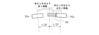
- the swinging width W of the drive gear 30 at this time is set to a half pitch (1 / 2P) of the interval between the engagement holes 30a in one circumferential direction and the opposite direction, as shown in FIG. Has been.
- the swing width W of the drive gear 30 is a half pitch (1 / 2P) of the interval between the engagement holes 30a.
- the total is 30 ° by 15 °.
- the drive gear 30 is swung to engage the engagement hole 30a with the lock member 60.
- the lock member 60 can be inserted into the engagement hole 30a.
- the lock member 60 can be reliably inserted into the engagement hole 30a, and the reliability of the apparatus is improved.
- the rotation amount for rotating the drive gear 30 for phase alignment of the engagement holes 30 a is suppressed to be equal to or less than a half pitch of the interval between the engagement holes 30 a. be able to. For this reason, it is possible to reduce the influence on the stop position of the ball screw 22 in the linear motion direction.
- the amount of rotation of the drive gear 30 for phase alignment can be reduced compared with the case where the drive gear 30 is rotated in one direction.
- the influence on the stop position can be reduced, and the stop position in the linear motion direction can be held with high accuracy.
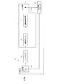
- FIG. 16 shows an example of a control flow when performing the locking operation.
- the locking operation will be described with reference to FIG.
- the lock sensor 69 detects whether or not the lock member 60 has been normally inserted into the engagement hole 30a. If the lock sensor 69 is not turned ON even when the lock member 60 is moved forward (when the lock member 60 does not contact the lock sensor 69), the lock member 60 is normally inserted into the engagement hole 30a.
- a retry operation is performed in which the lock member 60 is temporarily retracted and the lock member 60 is advanced again. Further, in order to measure the timing of shifting to the retry operation, the lock operation time is counted, and if the lock sensor 69 does not turn on even if the predetermined time continues, the operation shifts to the retry operation. Further, the number of retry operations is also counted, and if the lock sensor 69 is not turned ON even if the retry operation is performed a predetermined number of times, it is determined that the lock state will not be entered even if the retry operation is further performed. The lock operation is terminated.
- step 3 counting of the lock operation time is started (step 3), the drive gear 30 is started to swing (step 4), the lock motor 64 is rotated forward, and the lock member 60 starts moving forward (step 5).
- This lock sensor ON time is a time set to prevent erroneous detection due to switch chattering (ON / OFF swing) when the lock sensor 69 is turned ON.
- the lock sensor ON time is set to 0.6 seconds, and waiting for 0.6 seconds to elapse after the lock sensor 69 is turned on avoids erroneous detection due to chattering.
- step 7 it is confirmed whether or not the lock operation time has exceeded 3 seconds (step 7). If it has not exceeded 3 seconds, subsequently, it is confirmed whether or not the lock sensor 69 has been turned on (step 8). .
- step 9 when the lock sensor 69 is turned ON, counting of the lock sensor ON time is started in order to avoid the erroneous detection due to chattering (step 9). Then, it is confirmed whether or not the lock sensor ON time exceeds 0.6 seconds (step 10). If the lock sensor ON time is ON after 0.6 seconds, the lock member 60 is inserted into the engagement hole 30a. The swinging of the drive gear 30 is stopped (step 11), the forward movement of the lock member 60 is stopped (step 12), and the locking operation is finished.
- step 8 when the lock sensor 69 has not yet been turned ON in the above-described ON / OFF determination of the lock sensor 69 (step 8) and the lock operation time has exceeded 3 seconds (in the case of “Yes” in step 7).
- the drive gear 30 is temporarily stopped from swinging (step 13), and the operation proceeds to the retry operation.
- the maximum number of times this retry operation is executed is three times, it is confirmed whether the retry operation to be performed at the present time is not the fourth time (step 14), and if it is the third time, the retry operation is executed. To do.
- the lock motor 64 When performing the retry operation, the lock motor 64 is rotated in the reverse direction to temporarily retract the lock member 60 (step 15), and the number of retries is counted (added once) (step 16). Then, the operation shifts to the lock operation time count clear operation (step 2) immediately after the start of the lock operation, and the subsequent operations are executed again.
- the lock member 60 is inserted into the engagement hole 30a before the lock operation time exceeds 3 seconds (in the case of “Yes” in step 10)
- the swing of the drive gear 30 is stopped as described above.
- step 11 the forward movement of the lock member 60 is stopped (step 12), and the locking operation is terminated.
- step 14 if the lock member 60 is not inserted into the engagement hole 30a even if the same retry operation is repeated three times (if “Yes” in step 14), the lock member 60 is not changed even if the retry operation is further performed. Is not inserted into the engagement hole 30a, the forward movement of the lock member 60 is stopped (step 17), and the operation is terminated.
- the drive gear 30 is swung during the locking operation to facilitate the engagement of the lock member 60 with the engagement hole 30a. It may be swung. The reason is that when a load is applied from the drive gear 30 to the lock member 60 in the locked state, the lock member 60 may not be easily detached from the engagement hole 30a. Therefore, in this embodiment, during the unlocking operation, the lock member 60 is moved backward while swinging the drive gear 30 in one circumferential direction and the opposite direction so that the locked state can be reliably released. Yes.
- FIG. 17 is a diagram illustrating an example of a control flow when performing the unlocking operation.
- the lock sensor 69 detects whether or not the lock member 60 has been normally removed from the engagement hole 30a. If the lock sensor 69 is not turned off even if the lock member 60 is retracted (if the contact of the lock member 60 with the lock sensor 69 is not released), the lock member 60 is removed from the engagement hole 30a.
- a retry operation is performed in which the lock member 60 is once moved forward and the lock member 60 is moved backward again. Further, in order to measure the timing of shifting to the retry operation, the unlocking operation time is counted, and if the lock sensor 69 does not turn OFF even if the predetermined time continues, the operation shifts to the retry operation. Further, the number of retry operations is also counted, and if the lock sensor 69 is not turned off even if the retry operation is performed a predetermined number of times, it is determined that the lock release state is not obtained even if the retry operation is performed further. The unlocking operation is terminated at the time. The flow shown in FIG.
- FIG. 18 is a diagram showing another control flow of the locking operation.
- the drive gear 30 is swung and the lock member 60 is advanced.
- the lock member 60 comes into contact with the contact 69 a of the lock sensor 69, and its advance / retreat position is detected.
- the predetermined time in this example, 0.1 second
- the forward movement of the lock member 60 is stopped.
- the swing of the drive gear 30 is also stopped. Thereby, the lock member 60 is completely inserted into the engagement hole 30a, and is held in a locked state in which the lock member 60 can be engaged with the engagement hole 30a.
- the position of the lock member 60 is detected by the lock sensor 69 when at least the distal end portion of the lock member 60 starts to be inserted into the engagement hole 30a.
- the forward movement of the lock member 60 is stopped after a lapse of time.
- the lock member 60 can be reliably inserted into the engagement hole 30a. That is, the timing of stopping the advancement of the lock member 60 is counted at least after the lock member 60 starts to be inserted into the engagement hole 30a and after a predetermined time has elapsed, whereby the lock member 60 with respect to the engagement hole 30a is It can be managed so that the insertion state does not become insufficient or excessive.
- the predetermined time from when the position of the lock member 60 is detected to when the advance of the lock member 60 is stopped can be changed as appropriate.
- the tip of the lock member 60 is inclined at the timing when the position of the lock member 60 is detected by the lock sensor 69. It may be the timing at which the insertion of the surface 30b is started or the timing at which the tip of the lock member 60 passes through the inclined surface 30b.
- the displacement of the stop position in the linear motion direction (the displacement X in the linear motion direction of the output shaft of the electric actuator) can be suppressed within the range of 0.1 [mm] to 0.2 [mm]. .
- FIG. 20 shows an electric actuator 1 according to still another embodiment of the present invention.
- the electric actuator 1 shown in FIG. 20 eliminates the speed reduction mechanism portion 9 and directly connects the motor portion 8 and the driving force transmission portion 4.
- the rolling bearing 33 on the transmission gear case 29 side that press-fits the gear boss 32 and supports the gear boss 32 is omitted.
- the motor adapter 19 to which the drive motor 10 is attached is replaced with another shape that matches the mating shape of the mating member because the mating mating member changes from the reduction gear case 17 to the transmission gear case 29.
- Other configurations are the same as those of the embodiment shown in FIG.
- the electric actuator 1 of the embodiment shown in FIG. 20 is basically the same as the above embodiments except that the driving force from the driving motor 10 is directly transmitted to the driving force transmission unit 4 without passing through the speed reduction mechanism unit 9. Since the operation is controlled in the same manner, the description regarding the control and operation is omitted.
- the lock mechanism unit 7 is on the opposite side of the drive unit 30 from the drive unit 2, and the rotation center of the drive gear 30 is The electric actuator 1 can be reduced in size by being arranged on the side of the motion conversion mechanism 3 in the radial direction with respect to the line X.
- the lock mechanism unit 7 is configured to engage with the drive gear 30 on the side of the motion conversion mechanism unit 3 with respect to the rotation center line X, it is easy to realize downsizing.
- the lock mechanism unit 7 can be disposed close to the motion conversion mechanism unit 3 without considering interference with the drive unit 2. Miniaturization can be realized. As a result, it is possible to reduce the size of a device or device on which the electric actuator is mounted. Therefore, the configuration of the electric actuator according to the present invention includes, for example, an electric parking brake mechanism for an automobile including a two-wheeled vehicle, an electric hydraulic brake mechanism, an electric shift switching mechanism, an electric power steering, and a 2WD / 4WD electric motor. It is also suitable when developing a variety of products, such as switching mechanisms and electric shift switching mechanisms for outboard motors (for ship propulsion devices).
- the lock mechanism part 7 may use not only what uses a sliding screw apparatus but a ball screw apparatus.
- a configuration is adopted in which the sliding screw shaft 62 is rotated to linearly move the sliding screw nut 61.
- the sliding screw nut 61 is rotated to linearly move the sliding screw shaft 62.
- the sliding screw nut 61 is fixed to the output shaft 64 a of the locking motor 64 and the sliding screw shaft 62 is fixed to the locking member 60, whereby the sliding screw nut 61 is rotated by driving the locking motor 64, and the sliding screw It is possible to linearly move the shaft 62 and the lock member 60 integrally.
- the lock motor (rotary motor) 64 is used as a drive source for moving the lock member 60 backward in order to release the lock state. It may be used as a drive source (for advancing the member 60) or as a drive source for switching the lock member 60 to both the locked state and the unlocked state (for moving the lock member 60 forward and backward). May be.
- the support bearing 40 that supports the motion conversion mechanism 3 is not limited to a configuration using a double-row angular ball bearing, and a pair of single-row angular ball bearings may be used in combination. Further, as the support bearing 40, other than the angular ball bearing, for example, another double row bearing using a deep groove ball bearing or the like can be applied.
- the motion conversion mechanism 3 may be a sliding screw device.
- the ball screw 22 is preferable from the viewpoint of reducing the rotational torque and reducing the size of the drive motor 10.
- the speed reduction mechanism 9 may be a speed reduction mechanism other than the planetary gear speed reduction mechanism 18.
Landscapes
- Engineering & Computer Science (AREA)
- General Engineering & Computer Science (AREA)
- Mechanical Engineering (AREA)
- Power Engineering (AREA)
- Transmission Devices (AREA)
- Connection Of Motors, Electrical Generators, Mechanical Devices, And The Like (AREA)
Abstract
駆動部2と、駆動部2からの回転運動を駆動部2の出力軸と平行な軸方向の直線運動に変換する運動変換機構部3と、駆動部2から運動変換機構部3へ駆動力を伝達する伝達ギヤ機構28を有する駆動力伝達部4と、運動変換機構部3の駆動を防止するロック機構部7を備える電動アクチュエータであって、伝達ギヤ機構28は、駆動部2側に配置される第1歯車30と、運動変換機構部3側に配置される第2歯車31とを有し、ロック機構部7は、第1歯車30に対して駆動部2とは反対側であって、第1歯車30の回転中心線Xに対して運動変換機構部3側に配置される。
Description
本発明は、電動アクチュエータに関する。
近年、車両等の省力化、低燃費化のために電動化が進み、例えば、自動車の自動変速機やブレーキ、ステアリング等の操作を電動機の力で行うシステムが開発され、市場に投入されている。このような用途に使用されるアクチュエータとして、電動機の回転運動を直線方向の運動に変換するボールねじ機構を用いた電動リニアアクチュエータが知られている。
ところで、ボールねじ機構は、操作対象装置への駆動力伝達効率が非常に良い反面、操作対象装置側からボールねじに外力が入力された場合にボールねじ軸が軸方向に移動してしまうことがある。斯かる課題に対して、従来、操作対象装置側からの逆入力に対してボールねじの駆動を防止するロック機構を備えたものが提案されている。
例えば、特許文献1では、図21に示すように、電動モータ100からボールねじ200へ駆動力を伝達する歯車40対して係脱自在なロック部材としてのシャフト300を設け、このシャフト300によって歯車400の回転を阻止することで、ボールねじ200の駆動を防止するようにしている。
しかしながら、上記特許文献1に記載の構成では、シャフト300が、歯車400の回転中心に対してボールねじ200から半径方向に遠い位置に配置されているため、シャフト300とボールねじ200との軸間距離が長くなって、電動アクチュエータが大型化し、設置に必要なスペースが大きくなるといった課題がある。
そこで、本発明は、小型化を実現できる電動アクチュエータを提供することを目的とする。
前述の目的を達成するための技術的手段として、本発明は、駆動部と、駆動部からの回転運動を駆動部の出力軸と平行な軸方向の直線運動に変換する運動変換機構部と、駆動部から運動変換機構部へ駆動力を伝達する伝達ギヤ機構を有する駆動力伝達部と、運動変換機構部の駆動を防止するロック機構部を備える電動アクチュエータであって、伝達ギヤ機構は、駆動部側に配置される第1歯車と、運動変換機構部側に配置される第2歯車とを有し、ロック機構部は、第1歯車に対して駆動部とは反対側であって、第1歯車の回転中心線に対して運動変換機構部側に配置されることを特徴とする。
このように、ロック機構部が、第1歯車に対して駆動部とは反対側であって、第1歯車の回転中心線に対して運動変換機構部側に配置されることで、ロック機構部を、駆動部との干渉を考慮することなく運動変換機構部に対して接近させて配置することができる。これにより、電動アクチュエータの小型化を図れるようになる。
また、前述の目的を達成するための技術的手段として、本発明は、駆動部と、駆動部からの回転運動を駆動部の出力軸と平行な軸方向の直線運動に変換する運動変換機構部と、駆動部から運動変換機構部へ駆動力を伝達する伝達ギヤ機構を有する駆動力伝達部と、運動変換機構部の駆動を防止するロック機構部を備える電動アクチュエータであって、伝達ギヤ機構は、駆動部側に配置される第1歯車と、運動変換機構部側に配置される第2歯車とを有し、ロック機構部は、第1歯車に対してその回転中心線よりも運動変換機構部側で係合することで、第1歯車の回転を規制して運動変換機構部の駆動を防止することを特徴とする。
このように、ロック機構部が第1歯車に対してその回転中心線よりも運動変換機構部側で係合するような構成にすることで、ロック機構部を運動変換機構部に接近させて配置しやすくなり、電動アクチュエータの小型化を実現しやすくなる。
第1歯車にロック機構部を係合させるにあたっては、第1歯車の軸方向と交差する側面に、ロック機構部が係合する係合孔を形成することが好ましい。この場合、ロック機構部が第1歯車の歯に対して係合しないため、係合による歯への負荷を回避でき、信頼性が向上する。
上記ロック機構部は、係合孔に係脱可能なロック部材と、回転モータの回転運動を直線運動に変換してロック部材を係合孔に係合するロック状態とロック状態が解除されるロック解除状態との少なくとも一方の状態となるように駆動させる滑りねじ装置を有するものとすることができる。ロック機構部に滑りねじ装置を用いることで、部品数の少ない簡素な構成で直線運動を実現できるため、より一層の小型化を図れるようになる。
さらに、アクチュエータケースが、滑りねじ装置の直線運動する部材の回転を規制する回転規制部を有することで、回転規制部材を別途設けなくてもよくなり、小型化に有利となる。
例えば、滑りねじ装置を構成する滑りねじナットと滑りねじ軸の一方をロック部材に固定すると共に、他方を回転モータの出力軸に固定し、ロック部材の先端部側を平板状に形成し、アクチュエータケースにロック部材の先端部側が挿入される断面矩形の貫通孔を形成することで、アクチュエータケースに回転規制部としての機能をもたせることができる。すなわち、この場合、平板状に形成されたロック部材の先端部側が断面矩形に形成された貫通孔に挿入されることで、貫通孔内でのロック部材の回転が規制されるので、ロック部材に固定される滑りねじナット又は滑りねじ軸の回転が規制され直線運動が可能となる。
上記のように、ロック部材と貫通孔との間で回転を規制する場合、ロック部材の先端部側は、回転モータの出力軸と同軸上に配置されることが好ましい。このような構成とすることで、ロック部材と貫通孔との接触箇所(回転規制箇所)の位置が、回転モータの回転中心線から半径方向に近い位置になるため、回転規制箇所で受けるモーメントが小さくなり、ロック部材の直線運動に対する抵抗を低減することができる。これにより、ロック部材の作動性が向上し、電動アクチュエータの信頼性が向上する。
また、上記ロック機構部は、ロック部材をロック状態となる方向に付勢するばねを有し、回転モータは、駆動部が駆動する際に、ばねの付勢力に抗してロック部材をロック解除状態に切り換えるように駆動させるようにしてもよい。この場合、回転モータに電力を供給しなくても、ばねの付勢力によってロック状態を保持することができる。
また、駆動部の回転が第1歯車から第2歯車へ減速されて伝達される構成としてもよい。この場合、第1歯車から第2歯車へ回転トルクが大きくなって伝達される。従って、上記のように、ロック機構部が係合する相手ギヤを回転トルクの小さい第1歯車とすることで、回転トルクの大きい第2歯車と係合するよりも、係合時にロック機構部にかかる負荷を低減することができる。また、この場合、ロック機構部の係合相手が、回転速度の速い第1歯車であることで、減速後の第2歯車である場合よりも、細かく位置決めすることができ、運動変換機構部を停止させる位置精度が向上する。
また、電動アクチュエータは、運動変換機構部の直線運動する軸部を収容する軸ケースを備え、軸ケースは、ロック機構部を保持するホルダ部を有するものであってもよい。斯かる軸ケースを備える電動アクチュエータにおいては、上記のように、ロック機構部が運動変換機構部に対して接近して配置されることで、軸ケースの小型化を図れる。
また、ロック部材を前進させて係合孔に係合させる際、駆動部を駆動させることでギヤを周方向の一方とその反対方向とに揺動させ、ロック部材に対する係合孔の周方向位相合わせを行うようにしてもよい。
このように、ギヤを揺動させてロック部材に対する係合孔の周方向位相合わせを行うことで、係合孔とロック部材との周方向位相がずれていたとしても、ロック部材を係合孔に対して確実に挿入することができる。しかも、ギヤを一方向に回転させて係合孔の位相合わせをする場合に比べて少ない回転量で位相合わせすることができる。このため、電動アクチュエータの直動方向の停止位置に与える影響も少なく、精度良く位置保持することができる。
上記電動アクチュエータは、ロック部材の進退位置を検知するロックセンサを備え、ロックセンサは、ギヤを揺動させながらロック部材を前進させて、その先端部が少なくとも係合孔に挿入され始めたときに当該ロック部材の位置を検知し、ロックセンサがロック部材の位置を検知してから、所定時間経過後にロック部材の前進を停止するようにしてもよい。
このように、ロック部材の先端部が少なくとも係合孔に挿入され始めたときに、ロックセンサによってロック部材の位置を検知し、その検知したタイミングから所定時間経過後にロック部材の前進を停止することで、ロック部材を係合孔に対して確実に挿入させることができる。すなわち、ロック部材の前進を停止するタイミングを、少なくともロック部材が係合孔に挿入され始めたときからカウントして所定時間経過後とすることで、係合孔に対するロック部材の挿入状態が不十分になったり過度になったりすることがないように管理できる。
また、ギヤの揺動幅は、周方向の一方とその反対方向とにそれぞれ係合孔同士の間隔の半ピッチ分ずつとすることが望ましい。
このようなギヤの揺動幅に設定することで、係合孔をロック部材に対して確実に位相合わせすることができる。
さらに、ロック部材を後退させて係合孔から離脱させる際、駆動部を駆動させることでギヤを周方向の一方とその反対方向とに揺動させてもよい。
このように、ロック部材を後退させて係合孔から離脱させる際にギヤを揺動させることで、ロック部材とギヤ(係合孔の係合面)との引っ掛かりを回避し、ロック部材を係合孔から離脱させやすくなるため、確実にロック状態を解除できるようになる。
本発明によれば、小型化に好適な電動アクチュエータを提供することができる。
以下、添付の図面に基づき、本発明について説明する。なお、本発明を説明するための各図面において、同一の機能もしくは形状を有する部材や構成部品等の構成要素については、判別が可能な限り同一符号を付すことにより一度説明した後ではその説明を省略する。
図1は、本発明の一実施形態に係る電動アクチュエータの組み立て状態を示す縦断面図、図2は、前記電動アクチュエータの組み立て状態を示す外観斜視図、図3は、前記電動アクチュエータの分解斜視図である。
図1に示すように、本実施形態の電動アクチュエータ1は、駆動力を発生させる駆動部2と、駆動部2からの回転運動を直線運動に変換する運動変換機構部3と、駆動部2から運動変換機構部3へ駆動力を伝達する駆動力伝達部4と、運動変換機構部3を支持する運動変換機構支持部5と、運動変換機構部3の運動を出力する操作部6と、運動変換機構部3の駆動を防止するロック機構部7を主な構成とする。また、駆動部2は、モータ部8と減速機構部9とで構成される。
上記電動アクチュエータ1を構成する各部分は、それぞれケースを有し、各ケース内に構成部品が収容されている。具体的に、モータ部8は、駆動用モータ10を収容するモータケース11を有し、減速機構部9は、減速ギヤ機構16を収容する減速ギヤケース17を有する。また、駆動力伝達部4は、伝達ギヤ機構28を収容する伝達ギヤケース29を有し、運動変換機構支持部5は、支持軸受40を収容する軸受ケース41を有する。そして、モータ部8と減速機構部9、減速機構部9と駆動力伝達部4、駆動力伝達部4と運動変換機構支持部5は、互いにケースごと連結分離可能に構成されている。さらに、軸受ケース41に対しては、軸ケース50が連結分離可能に構成されている。以下、電動アクチュエータ1を構成する各部の詳細な構成について説明する。
モータ部8は、運動変換機構部3を駆動させる駆動用モータ(DCモータ)10と、駆動用モータ10を収容するモータケース11を主な構成とする。モータケース11は、内部に駆動用モータ10が収容される有底円筒状のケース本体12と、ケース本体12の底部12aから外部に突出する突出部13とを有する。突出部13は、ケース本体12の内部空間と連通する孔部13aが形成されている。この孔部13aは、突出部13の外面を覆う樹脂製の封止部材14によって封止されている。
駆動用モータ10は、ケース本体12の開口部12dから内部に挿入された状態で、駆動用モータ10の挿入方向奥側の端面がケース本体12の底部12aに当接する。また、底部12aの中央部には嵌合孔12cが形成されており、この嵌合孔12cに駆動用モータ10の挿入方向奥側の突起10bが嵌合することで、突起10bから突出する出力軸10aの後端(図1の左端部)がモータケース11の底部12aと干渉するのが回避される。さらに、ケース本体12の周壁部12bの内周面は、開口部12d側から底部12a側に向かってテーパ状に縮径しており、駆動用モータ10がケース本体12内に挿入されると駆動用モータ10の挿入方向奥側の外周面が周壁部12bの内周面に接触するように構成されている。このように、駆動用モータ10は、ケース本体12内に挿入された状態で、ケース本体12の内周面との接触と嵌合孔12cとの嵌合によって支持される。
また、モータケース11を開口部12d側から見た図4に示すように、ケース本体12には、駆動用モータ10を動力電源に接続するための一対のバスバー15が取り付けられている。各バスバー15の一端部15aはモータ端子10cに対してかしめて接続され、他端部15bはケース本体12から外部に露出している(図2、図3参照)。この外部に露出するバスバー15の端部15bが動力電源に接続される。
次に、減速機構部9について説明する。
図1に示すように、減速機構部9は、駆動用モータ10の駆動力を減速して出力する減速ギヤ機構16と、減速ギヤ機構16を収容する減速ギヤケース17を主な構成とする。減速ギヤ機構16は、複数の歯車等から成る遊星歯車減速機構18で構成される。なお、遊星歯車減速機構18の詳細な構成については後述する。
図1に示すように、減速機構部9は、駆動用モータ10の駆動力を減速して出力する減速ギヤ機構16と、減速ギヤ機構16を収容する減速ギヤケース17を主な構成とする。減速ギヤ機構16は、複数の歯車等から成る遊星歯車減速機構18で構成される。なお、遊星歯車減速機構18の詳細な構成については後述する。
減速ギヤケース17には、遊星歯車減速機構18を駆動用モータ10側とは反対側から収容するための収容凹部17aが設けられている。また、減速ギヤケース17には、モータ取付部材としてのモータアダプタ19が取付可能に構成されている。モータアダプタ19は筒状の部材で、その内周面に駆動用モータ10の出力側(図1の右側)の突起10dが挿入されて嵌合される。減速ギヤケース17には、モータアダプタ19が嵌合される嵌合孔17bが形成されており、この嵌合孔17bに対してモータアダプタ19が駆動用モータ10側から挿入されて取り付けられる。
減速ギヤケース17は、モータケース11とこれとは反対側に配置される後述の伝達ギヤケース29に対して嵌合可能に構成されている。減速ギヤケース17のうち、モータケース11側に配置される部分がモータケース11の開口部12d側に内嵌され、伝達ギヤケース29側に配置される部分が伝達ギヤケース29に外嵌される。また、減速ギヤケース17は、モータケース11に対して嵌合された状態でモータアダプタ19と一緒にボルト21(図3、図6参照)によって駆動用モータ10に締結される。減速ギヤケース17の駆動用モータ10側には、減速ギヤケース17とモータケース11とが嵌合された状態で、駆動用モータ10から突出するモータ端子10cおよびこれにかしめられたバスバー15の端部15aとの干渉を回避するための凹部17cが形成されている。また、モータケース11の内周面と嵌合する減速ギヤケース17の外周面(嵌合面)には、Oリング20を装着するための装着溝17dが形成されている。
続いて、運動変換機構部3について説明する。
運動変換機構部3は、ボールねじ22で構成される。ボールねじ22は、回転体としてのボールねじナット23と、直線運動する軸部であるボールねじ軸24と、多数のボール25および循環部材としてのこま26を主な構成とする。ボールねじナット23の内周面とボールねじ軸24の外周面にそれぞれ螺旋状溝23a,24aが形成されている。両螺旋状溝23a,24aの間にボール25が充填され、こま26が組み込まれ、これにより2列のボール25が循環する。
運動変換機構部3は、ボールねじ22で構成される。ボールねじ22は、回転体としてのボールねじナット23と、直線運動する軸部であるボールねじ軸24と、多数のボール25および循環部材としてのこま26を主な構成とする。ボールねじナット23の内周面とボールねじ軸24の外周面にそれぞれ螺旋状溝23a,24aが形成されている。両螺旋状溝23a,24aの間にボール25が充填され、こま26が組み込まれ、これにより2列のボール25が循環する。
ボールねじナット23は、駆動用モータ10からの駆動力を受けて正方向または逆方向に回転する。一方、ボールねじ軸24は、その後端部(図1の右端部)に設けられた回転規制部材としてのピン27によって回転が規制されている。このため、ボールねじナット23が回転すると、ボール25が両螺旋状溝23a,24aおよびこま26に沿って循環し、ボールねじ軸24が軸方向に進退する。なお、図1は、ボールねじ軸24が最も図の右側へ後退した初期位置に配置された状態を示している。また、ボールねじ軸24は、駆動用モータ10の出力軸10aと平行に配置されており、駆動用モータ10からの回転運動はボールねじ軸24によって出力軸10aと平行な軸方向の直線運動に変換される。ボールねじ軸24の前進方向の先端部(図1の左端部)が、操作対象装置を操作する操作部(アクチュエータヘッド)6として機能する。
続いて、駆動力伝達部4について説明する。
駆動力伝達部4は、駆動部2が有する駆動用モータ10から運動変換機構部3であるボールねじ22へ駆動力を伝達する伝達ギヤ機構28と、伝達ギヤ機構28を収容する伝達ギヤケース29を主な構成とする。伝達ギヤ機構28は、第1歯車としての駆動側のドライブギヤ30と、これと噛み合う第2歯車としての被駆動側のドリブンギヤ31とを有する。
駆動力伝達部4は、駆動部2が有する駆動用モータ10から運動変換機構部3であるボールねじ22へ駆動力を伝達する伝達ギヤ機構28と、伝達ギヤ機構28を収容する伝達ギヤケース29を主な構成とする。伝達ギヤ機構28は、第1歯車としての駆動側のドライブギヤ30と、これと噛み合う第2歯車としての被駆動側のドリブンギヤ31とを有する。
ドライブギヤ30の回転中心部にはギヤボス32が圧入嵌合されている。ドライブギヤ30は、このギヤボス32を介して伝達ギヤケース29と後述の軸受ケース41の両ケースに装着される2つの転がり軸受33,34によって回転可能に支持される。一方、ドリブンギヤ31は、ボールねじナット23の外周面に圧入嵌合され固定されている。駆動用モータ10からの駆動力が遊星歯車減速機構18を介してドライブギヤ30に伝達されると、ドリブンギヤ31とボールねじナット23が一体的に回転し、ボールねじ軸24が進退する。
伝達ギヤケース29は、内部にドライブギヤ30およびドリブンギヤ31が収容される収容凹部29aを有する。また、伝達ギヤケース29には、ギヤボス32を挿通するための挿通孔29bが形成され、挿通孔29bの内周面には、ギヤボス32を支持する一方の転がり軸受33が装着される軸受装着面29cが形成されている。また、伝達ギヤケース29は、減速ギヤケース17の内周面と嵌合する環状突起29dを有する。この環状突起29dの外周面(嵌合面)には、Oリング35を装着するための装着溝29eが形成されている。また、伝達ギヤケース29の軸受ケース41側の面には、軸受ケース41と嵌合する溝状の嵌合凹部29fが形成されている。
また、伝達ギヤケース29は、ボールねじ軸24の先端部側(図1の左側)へ突出する円筒部29gを有する。この円筒部29gは、伝達ギヤケース29内にドリブンギヤ31が収容され、これにボールねじ22が組み付けられた状態で、ボールねじ軸24の周囲を覆うように配置される部分である。円筒部29gとボールねじ軸24の間には、伝達ギヤケース29内への異物侵入を防止するブーツ36が取り付けられる。ブーツ36は、大径端部36aと小径端部36bとこれらを繋いで軸方向に伸縮する蛇腹部36cで構成されている。大径端部36aが円筒部29gの外周面の取付部位にブーツバンド37によって締め付け固定され、小径端部36bがボールねじ軸24の外周面の取付部位にブーツバンド38によって締め付け固定される。また、円筒部29gには、ブーツ36が伸縮したときに内外で通気させるための通気孔29hが設けられている。また、上記モータケース11には、ブーツ36の周囲に配置されるブーツカバー39が一体に設けられている。
続いて、運動変換機構支持部5について説明する。
運動変換機構支持部5は、運動変換機構部3であるボールねじ22を支持する支持軸受40と、支持軸受40を収容する軸受ケース41を主な構成とする。支持軸受40は、外輪42と内輪43とこれらの間に介在する複列のボール44を主要な構成要素とする背面合わせの複列アンギュラ玉軸受で構成される。
運動変換機構支持部5は、運動変換機構部3であるボールねじ22を支持する支持軸受40と、支持軸受40を収容する軸受ケース41を主な構成とする。支持軸受40は、外輪42と内輪43とこれらの間に介在する複列のボール44を主要な構成要素とする背面合わせの複列アンギュラ玉軸受で構成される。
支持軸受40は、軸受ケース41と一体に形成されたスリーブ45内に収容され、スリーブ45の内周面に装着された止め輪46で固定されている。また、支持軸受40は、ボールねじナット23の外周面に対して上記ドリブンギヤ31よりもボールねじ軸24の後端側(図1の右側)に圧入嵌合されて固定される。ボールねじナット23の外周面に固定される支持軸受40とドリブンギヤ31は、ボールねじナット23のドリブンギヤ31側に設けられた規制突起23bと、支持軸受40側に装着された規制部材47によって軸方向の移動が規制される。規制部材47は、一対の半円弧状部材で構成され、これらを環状に組み合わせた状態でボールねじナット23の外周面に装着される。さらに、ボールねじナット23の外周面には、規制部材47を保持する押さえ用カラー48と、この押さえ用カラー48の軸方向の脱落を防止する止め輪49が装着される。
軸受ケース41の伝達ギヤケース29側には、伝達ギヤケース29の嵌合凹部29fと嵌合する突条部41aが設けられている。また、軸受ケース41の伝達ギヤケース29側には、軸受ケース41が伝達ギヤケース29と嵌合した状態で、伝達ギヤケース29から突出するギヤボス32の一部が収容されるギヤボス収容部41bが設けられている。このギヤボス収容部41bの内周面には、ギヤボス32を支持する転がり軸受34を装着するための軸受装着面41cが形成されている。
軸受ケース41の伝達ギヤケース29側とは反対側には、ボールねじ軸24の後端部側(図1の右端部側)を収容する有底筒状の軸ケース50がボルト51(図3参照)で締結可能に構成されている。軸ケース50の軸受ケース41との当接面には、Oリング52を装着するための装着溝50aが形成されている。また、軸ケース50の内周面には、ボールねじ軸24に設けられたピン27の両端部が挿入される案内溝50bが軸方向に延在するように形成されている。ピン27の両端部にはそれぞれガイドカラー53が回転可能に装着されており、ボールねじ軸24が軸方向に進退する際、ガイドカラー53が案内溝50bに沿って回転しながら移動する。
図3に示すように、上記モータケース11、減速ギヤケース17、伝達ギヤケース29、軸受ケース41の各ケースの半径方向外側周辺には、これらを組み立て締結するためのボルト54を挿通するボルト挿通孔11a,17e,29i,41dが設けられている。さらに、伝達ギヤケース29と軸受ケース41の両方の半径方向外側周辺には、組立てられた電動アクチュエータ1を設置場所に取付けるための貫通孔29j,41eが設けられている。
ここで、図1、図5および図6に基づき遊星歯車減速機構18について説明する。
図5は、図1のA-A線で矢視した横断面図、図6は、遊星歯車減速機構18の分解斜視図である。
図5は、図1のA-A線で矢視した横断面図、図6は、遊星歯車減速機構18の分解斜視図である。
遊星歯車減速機構18は、リングギヤ55と、サンギヤ56と、複数の遊星ギヤ57と、遊星ギヤキャリア58(図1参照)と、遊星ギヤホルダ59(図1参照)から構成される。リングギヤ55は、軸方向に突出する複数の凸部55aを有し、減速ギヤケース17の収容凹部17aには凸部55aと同数の係合凹部17fが設けられている(図1参照)。減速ギヤケース17の係合凹部17fにリングギヤ55の凸部55aを位相合わせして組み込むことで、リングギヤ55が減速ギヤケース17に対して回り止めされて収容される。
リングギヤ55の中央にサンギヤ56が配置され、サンギヤ56には駆動用モータ10の出力軸10aが圧入嵌合される。また、リングギヤ55とサンギヤ56との間には各遊星ギヤ57がこれらと噛み合うように配置されている。各遊星ギヤ57は、遊星ギヤキャリア58と遊星ギヤホルダ59によって回転可能に支持されている。遊星ギヤキャリア58はその中央部に円筒部58aを有し、円筒部58aはギヤボス32の外周面と転がり軸受33の内周面との間に圧入嵌合されている(図1参照)。なお、他方の転がり軸受34の内周面とギヤボス32の外周面との間には、環状のカラー75が装着されている。
上記の如く構成された遊星歯車減速機構18は、駆動用モータ10が回転駆動すると、駆動用モータ10の出力軸10aに連結されたサンギヤ56が回転し、これに伴って各遊星ギヤ57が自転しながらリングギヤ55に沿って公転する。そして、この遊星ギヤ57の公転運動により遊星ギヤキャリア58が回転する。これにより、駆動用モータ10の回転が減速されてドライブギヤ30に伝達され、回転トルクが増加する。このように、遊星歯車減速機構18を介して駆動力が伝達されることで、ボールねじ軸24の出力が大きく得られるようになり、駆動用モータ10の小型化を図ることが可能である。
続いて、図1、図7および図8に基づき、ロック機構部7について説明する。図7は、軸ケース50と、これに取り付けられるロック機構部7の分解斜視図、図8は、図1のB-B線で矢視した横断面図である。
ロック機構部7は、ロック部材60と、滑りねじナット61と、滑りねじ軸62と、ロック部材固定板63と、ロック用モータ(DCモータ)64と、ばね65を主な構成とする。ロック機構部7の組み立ては、まず、ロック部材60を、滑りねじナット61に対してロック部材固定板63を介してボルト84(図7参照)で締結する。次いで、ロック用モータ64を、軸ケース50に設けられたホルダ部66内に収容し、ホルダ部66から突出するロック用モータ64の出力軸64aに滑りねじ軸62を取り付ける。そして、滑りねじ軸62の外周にばね65を配置すると共に、ロック部材60が取り付けられた滑りねじナット61を滑りねじ軸62に対して螺合して装着する。このようにして、ロック機構部7の組み立てが完了する。
ホルダ部66は、有底筒状に形成され、その底部66aとは反対側にキャップ67が装着されている。ロック用モータ64がホルダ部66内に挿入され、キャップ67を装着した状態で、ロック用モータ64は、ホルダ部66の底部66aとキャップ67の内面に当接する。また、この状態で、ロック用モータ64の出力側(図1の左側)の突起64bがホルダ部66の底部66aに形成された嵌合孔66cに嵌合する。ロック用モータ64の本体外周面とホルダ部66の周壁部66bの内周面はいずれも円筒形ではない同形状に形成されているため、ホルダ部66の周壁部66b内にロック用モータ64が挿入されることで、ロック用モータ64の回転が規制される。このように、ホルダ部66にロック用モータ64が収容されることで、ホルダ部66によってロック用モータ64が保持され、ロック機構部7全体が保持される。また、キャップ67には、ロック用モータ64のモータ端子64dに接続されるケーブル68を挿通するための孔部67aが形成されている(図8参照)。
軸ケース50のホルダ部66が設けられた部分とこれに対向する軸受ケース41の部分には、それぞれロック機構収容凹部66d,41fが形成され、軸受ケース41側のロック機構収容凹部41fには貫通孔41gが形成されている。図1に示すように、軸ケース50が軸受ケース41に取り付けられた状態で、ロック機構収容凹部66d,41f内には、ホルダ部66から突出するロック用モータ64の出力軸64a、滑りねじ軸62、滑りねじナット61、ロック部材固定板63、ばね65およびロック部材60の一部が収容され、貫通孔41g内には、ロック部材60の平板状に形成された先端部側が挿入される。貫通孔41gは、ロック部材60の先端部側とほぼ同サイズで同形状の断面矩形の孔で構成されている(図9、図10参照)。また、軸ケース50が軸受ケース41に取り付けられた状態では、ばね65がホルダ部66の底部66aとロック部材固定板63との間で軸方向に圧縮され、この圧縮されたばね65によってロック部材60は前進する方向(図1の左側)へ常時付勢されている。
ロック部材60が前進する方向にはドライブギヤ30が配置されており、ドライブギヤ30にはロック部材60の先端部が係合可能な係合孔30aが形成されている。図1のC-C線で矢視した横断面図である図11に示すように、係合孔30aは、ドライブギヤ30の周方向に渡って複数設けられている。ロック部材60はこれらの係合孔30aのうちのいずれかに係合されることで、ドライブギヤ30の回転が規制される。また、各係合孔30aの入口部には傾斜面30bが形成されており、この傾斜面30bに沿ってロック部材60が係合孔30aにスムーズに挿入される。
軸受ケース41には、ロック状態を検知するためのロックセンサ69が装着されている(図8参照)。ロックセンサ69は、板バネ等の弾性部材で構成された接触子69aを有しており、ロック部材60が前進して係合孔30aに係合されると(ロック状態になると)、ロック部材60が接触子69aを押すことで、ロック状態となったことが検知される。
以下、ロック機構部7の動作について説明する。
ロック用モータ64に電力が供給されていない状態では、ロック部材60はばね65によって前進した位置に保持されており、ロック部材60の先端部がドライブギヤ30の係合孔30aに係合したロック状態にある。この状態から、ボールねじ軸24の駆動を開始するために駆動用モータ10に電力が供給されると、ロック用モータ64にも電力が供給され、ロック用モータ64はロック部材60を後退させる方向に駆動する。これにより、滑りねじ軸62が回転し、一方、滑りねじナット61は断面矩形の貫通孔41gに対するロック部材60の平板状先端部の挿入によって回転が規制されているため、滑りねじ軸62が回転すると、滑りねじナット61がばね65の付勢力に抗して後退し、これと一体的にロック部材60も後退する。これにより、ロック部材60の先端部がドライブギヤ30の係合孔30aから離脱し、ロック状態が解除される。こうして、ボールねじ軸24を駆動させている間は、ロック部材60が後退した位置に保持され、ドライブギヤ30がロックされない状態(ロック解除状態)に保持される。
ロック用モータ64に電力が供給されていない状態では、ロック部材60はばね65によって前進した位置に保持されており、ロック部材60の先端部がドライブギヤ30の係合孔30aに係合したロック状態にある。この状態から、ボールねじ軸24の駆動を開始するために駆動用モータ10に電力が供給されると、ロック用モータ64にも電力が供給され、ロック用モータ64はロック部材60を後退させる方向に駆動する。これにより、滑りねじ軸62が回転し、一方、滑りねじナット61は断面矩形の貫通孔41gに対するロック部材60の平板状先端部の挿入によって回転が規制されているため、滑りねじ軸62が回転すると、滑りねじナット61がばね65の付勢力に抗して後退し、これと一体的にロック部材60も後退する。これにより、ロック部材60の先端部がドライブギヤ30の係合孔30aから離脱し、ロック状態が解除される。こうして、ボールねじ軸24を駆動させている間は、ロック部材60が後退した位置に保持され、ドライブギヤ30がロックされない状態(ロック解除状態)に保持される。
その後、駆動用モータ10への電力供給が遮断され、ボールねじ軸24の駆動が停止すると、ロック用モータ64への電力供給も遮断される。これにより、ロック部材60を後退させておくための駆動力が生じなくなるため、ロック部材60はばね65によって前進する方向へ押し動かされる。そして、ロック部材60の先端部がドライブギヤ30の係合孔30aに係合することでロック状態となり、ドライブギヤ30の回転が規制される。
このように、ロック部材60によってドライブギヤ30の回転が規制されることで、ボールねじ軸24が進退しない状態で保持される。これにより、操作対象装置側からボールねじ軸24側へ外力が入力されたとしても、ボールねじ軸24の位置を所定の位置に保持しておくことができる。斯かる構成は、特に位置保持が必要なアプリケーションに電動アクチュエータを適用する場合に好適である。
本実施形態では、ロック用モータ64を駆動させることにより、ロック部材60を後退させるようにしているが、反対に、ロック部材60を前進させるために、ロック用モータ64を駆動させてもよい。また、ロック用モータ64を正逆回転させることで、ロック部材60を前進させたり後退させたりすることも可能である。
本実施形態の電動アクチュエータ1には、ボールねじ軸24のストロークを検出するためのストロークセンサ70が搭載されている(図2、図3参照)。ストロークセンサ70はセンサベース71に取り付けられ、センサベース71はモータケース11とブーツカバー39の間の外周面に設けられたセンサケース76にボルト72で締結固定されている。一方、ボールねじ軸24のブーツ36で覆われる部分の外周面には、センサターゲットとしての永久磁石73が取り付けられている(図1参照)。本実施形態では、永久磁石73は、周方向の一部で切り離された円筒状の弾性部材74を介してボールねじ軸24に取り付けられている。ボールねじ軸24が進退すると、ストロークセンサ70に対する磁石73の位置が変化し、これに伴って変化する磁力線の向きをストロークセンサ70によって検出することで、ボールねじ軸24の軸方向位置を把握することができる。
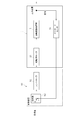
続いて、図12に基づき、ストロークセンサ70を用いたフィードバック制御について説明する。
図12に示すように、目標値が制御装置80に送られると、制御装置80のコントローラ81から駆動用モータ10に制御信号が送られる。なお、この目標値は、例えば、車両上位のECUに操作量が入力された際に、その操作量に基づいてECUが演算したストローク値である。
図12に示すように、目標値が制御装置80に送られると、制御装置80のコントローラ81から駆動用モータ10に制御信号が送られる。なお、この目標値は、例えば、車両上位のECUに操作量が入力された際に、その操作量に基づいてECUが演算したストローク値である。
制御信号を受け取った駆動用モータ10は回転駆動を開始し、この駆動力が上記遊星歯車減速機構18、ドライブギヤ30、ドリブンギヤ31、ボールねじナット23を介してボールねじ軸24に伝達されて、ボールねじ軸24が前進する。これにより、ボールねじ軸24の先端部側(アクチュエータヘッド側)に配置される操作対象装置が操作される。
このとき、ストロークセンサ70によってボールねじ軸24のストローク値(軸方向位置)が検出される。ストロークセンサ70によって検知された検出値は制御装置80の比較部82に送られ、検出値と上記目標値との差分が算出される。そして、検出値が目標値と一致するようになるまで、駆動用モータ10を駆動させる。このように、ストロークセンサ70によって検出されたストローク値がフィードバックされてボールねじ軸24の位置が制御されることで、本実施形態の電動アクチュエータ1を、例えば、シフトバイワイヤに適用した場合、シフト位置を確実にコントロールすることができる。
次に、図13に基づき、ストロークセンサ70に代えて圧力センサ83を用いた場合のフィードバック制御について説明する。
図13に示すように、この場合は、操作対象装置に圧力センサ83が設けられている。車両上位のECUに操作量が入力されると、ECUは要求される目標値(圧力指令値)を演算する。この目標値が制御装置80に送られ、コントローラ81から駆動用モータ10に制御信号が送られると、駆動用モータ10は回転駆動を開始する。これにより、ボールねじ軸24が前進し、ボールねじ軸24の先端部側(アクチュエータヘッド側)に配置される操作対象装置が加圧操作される。
図13に示すように、この場合は、操作対象装置に圧力センサ83が設けられている。車両上位のECUに操作量が入力されると、ECUは要求される目標値(圧力指令値)を演算する。この目標値が制御装置80に送られ、コントローラ81から駆動用モータ10に制御信号が送られると、駆動用モータ10は回転駆動を開始する。これにより、ボールねじ軸24が前進し、ボールねじ軸24の先端部側(アクチュエータヘッド側)に配置される操作対象装置が加圧操作される。
このときのボールねじ軸24の操作圧力は、圧力センサ83により検出され、この検出値と目標値に基づいて、上記ストロークセンサ70を用いる場合と同様に、ボールねじ軸24の位置がフィードバック制御される。このように、圧力センサ83によって検出された圧力値がフィードバックされてボールねじ軸24の位置が制御されることで、本実施形態の電動アクチュエータ1を、例えば、ブレーキバイワイヤに適用した場合、ブレーキの液圧を確実にコントロールすることができる。
本実施形態の電動アクチュエータ1の構成および動作については以上の通りである。以下、本実施形態の電動アクチュエータ1に関して、小型化に好適な構成部分について説明する。
図1に示すように、本実施形態では、ロック機構部7が、ドライブギヤ30に対して図の右側、すなわち駆動部2とは反対側に配置されている。このように、ロック機構部7を駆動部2とは反対側に配置することで、ロック機構7を配置する側では駆動部2との干渉を考慮しなくてもよくなる。仮に、ロック機構部7を駆動部2と同じ側に配置する場合は、駆動部2とロック機構部7との干渉を回避するために、ロック機構部7を駆動部2に対して軸方向にずらしたり、これと交差する半径方向又は周方向にずらしたりしなければならず、電動アクチュエータ1の軸方向又は径方向の大型化に繋がる。これに対し、本実施形態では、図1に示すように、ロック機構部7を駆動部2と同様に運動変換機構部3の直上(ボールねじ22の周方向において駆動部2と同位相位置)に配置でき、電動アクチュエータ1の大型化を回避することができる。また、重量バランスも良い構成となる。
さらに、本実施形態では、ロック機構部7が、ドライブギヤ30の回転中心線Xに対して図の下側、すなわち半径方向の運動変換機構部3側に配置されている。このように、ロック機構部7をドライブギヤ30の回転中心線Xに対して運動変換機構部3側に配置することで、ロック機構部7を運動変換機構部3に対して半径方向(直線運動方向と交差する方向)に接近させて配置することができる。同様に、軸ケース50における、ボールねじ軸24を収容する部分とロック機構部7を収容する部分(ホルダ部66)も、互いに接近させて配置することができる。これにより、軸ケース50が小型化し、電動アクチュエータ1の縦方向の小型化を図れるようになる。
なお、上記の「ロック機構部7がドライブギヤ30の回転中心線Xに対して運動変換機構部3側に配置される」とは、ロック機構7の縦寸法(図1における上下方向寸法)のうち、半分よりも多い部分が、ドライブギヤ30の回転中心線Xよりも運動変換機構部3側に配置されていることを意味する。すなわち、ロック機構部7の全体がドライブギヤ30の回転中心線Xよりも運動変換機構部3側に配置されている場合のほか、ロック機構7の一部(縦寸法の半分以下の部分)がドライブギヤ30の回転中心線Xよりも運動変換機構部3とは反対側に配置される場合であってもよい。
また、図1に示すように、本実施形態では、ロック機構部7はドライブギヤ30に対してその回転中心線Xよりも運動変換機構部3側で係合するように構成されている。このように構成することで、ロック機構部7を運動変換機構部3に接近させて配置しやすくなり、電動アクチュエータ1の縦方向の小型化を実現しやすくなる。
さらに、本実施形態では、ドライブギヤ30の軸方向と交差する側面に係合孔30aを形成し、この係合孔30aに対してロック機構部7が係合するようにしている。このようにすることで、ロック機構部7がドライブギヤ30の歯に対して係合しないため、係合による歯への負荷を回避でき、信頼性が向上する。
本実施形態では、ドライブギヤ30からドリブンギヤ31へ回転が等速で伝達されるようにしているが、ドライブギヤ30からドリブンギヤ31へ回転が減速して伝達されるようにしてもよい。この場合、ドライブギヤ30はドリブンギヤ31に比べて回転速度は速いが回転トルクは小さくなる。従って、ロック機構部7の係合相手となるギヤを、回転トルクの大きいドリブンギヤ31ではなく、回転トルクの小さいドライブギヤ30とすることで、係合時のロック機構部7への負荷を低減することができる。また、この場合、ロック機構部7の係合相手が、回転速度の速いドライブギヤ30であることで、減速後のドリブンギヤ31である場合よりも、細かく位置決めすることができ、運動変換機構部3を停止させる位置精度が向上する。
また、本実施形態では、ロック用モータ64の回転運動を直線運動に変換する機構に、滑りねじナット61と滑りねじ軸62から成る滑りねじ装置を用いている。このように、滑りねじ装置を用いることで、駆動源として回転モータを用いた構成において部品数の少ない簡素な構成で直線運動を実現できるため、より一層の小型化を図れるようになる。
上記のように、滑りねじ装置を用いる場合、滑りねじ装置の直線運動する部材の回転を規制する構成が必要となるが、本実施形態では、軸受ケース41に断面矩形の貫通孔41gを設け、この貫通孔41gに平板状のロック部材60を挿入することで、滑りねじ装置の直線運動する部材(滑りねじナット61)の回転を規制している。このように、アクチュエータケースの一部である軸受ケース41に回転規制部としての機能をもたせるようにすることで、滑りねじナット61の回転を規制する部材を別途設けなくてもよくなり、小型化に有利となる。
なお、本実施形態とは別の構成として、滑りねじナット61の外周面に突起を設け、この突起を軸受ケース41の内面に当接させることで、滑りねじナット61の回転を規制してもよい。ただし、滑りねじナット61の回転を規制する箇所がロック用モータ64の出力軸64aに対して半径方向に遠くなると、回転を規制する箇所で受けるモーメントが大きくなって、滑りねじナット61の直線運動に対する抵抗が大きくなることが考えられる。そのため、回転を規制する箇所は、なるべくロック用モータ64の出力軸64aに対して半径方向に近い位置であることが望ましい。この点、本実施形態では、ロック部材60の先端部側がロック用モータ64の出力軸64aと同軸上に配置されているため(図1、図8参照)、出力軸64aに対して半径方向に近い位置で回転規制することができ、滑りねじナット61への抵抗を低減することができる。これにより、ロック部材60の作動性が向上し、電動アクチュエータの信頼性が向上する。
以下、本発明の他の実施形態について説明する。なお、以下に説明する部分以外は、上記実施形態と基本的に同様の構成であるので重複する部分の説明については省略する。
本実施形態においても、上記実施形態と同様に、軸受ケース41には、ロック状態か否かを把握するためにロック部材60の進退位置を検知するロックセンサ69が装着されている(図8参照)。ロックセンサ69は、板バネ等の弾性部材で構成された接触子69aを有しており、ロック部材60が前進する際、ロック部材60が接触子69aを押すことで、ロック部材60の位置が検知される。
以下、ロック機構部7の動作について説明する。
ロック用モータ64に電力が供給されていない状態では、ロック部材60はばね65によって前進したロック位置に保持されており、ロック部材60の先端部がドライブギヤ30の係合孔30aに係合したロック状態にある。この状態から、ロック用モータ64が逆回転(ロック部材60を後退させる方向に回転)すると、これに伴って、滑りねじ軸62が回転する。このとき、滑りねじナット61は断面矩形の貫通孔41gに対するロック部材60の平板状先端部の挿入によって回転が規制されているため、滑りねじ軸62が回転すると、滑りねじナット61がばね65の付勢力に抗して後退し、これと一体的にロック部材60も後退する。これにより、ロック部材60の先端部がドライブギヤ30の係合孔30aから離脱し、ロック部材60がロック解除位置に保持されたロック解除状態となる。
ロック用モータ64に電力が供給されていない状態では、ロック部材60はばね65によって前進したロック位置に保持されており、ロック部材60の先端部がドライブギヤ30の係合孔30aに係合したロック状態にある。この状態から、ロック用モータ64が逆回転(ロック部材60を後退させる方向に回転)すると、これに伴って、滑りねじ軸62が回転する。このとき、滑りねじナット61は断面矩形の貫通孔41gに対するロック部材60の平板状先端部の挿入によって回転が規制されているため、滑りねじ軸62が回転すると、滑りねじナット61がばね65の付勢力に抗して後退し、これと一体的にロック部材60も後退する。これにより、ロック部材60の先端部がドライブギヤ30の係合孔30aから離脱し、ロック部材60がロック解除位置に保持されたロック解除状態となる。
その後、電動アクチュエータのボールねじ22の直動運動が停止し、再度ロック状態にする際は、ロック用モータ64を正回転させることで、ロック部材60を前進させる。そして、ロック部材60が前進すると、ロック部材60の先端部がドライブギヤ30の係合孔30aに挿入されて、ドライブギヤ30の回転がロック部材60との係合によって規制されるロック状態となる。
このように、ロック部材60によってドライブギヤ30の回転が規制されることで、ボールねじ軸24が進退しない状態で保持される。これにより、操作対象装置側からボールねじ軸24側へ外力が入力されたとしても、ボールねじ軸24の位置を所定の位置に保持しておくことができる。斯かる構成は、特に位置保持が必要なアプリケーションに電動アクチュエータを適用する場合に好適である。また、本実施形態のように、ロック部材60が係合するドライブギヤ30の係合部を、ドライブギヤ30の歯面ではなく、軸方向と交差する側面に設けられた係合孔30aとすることで、歯面に摩耗や変形が生じるのを回避することができ、電動アクチュエータの制御性を良好に維持することができる。
本実施形態では、ロック用モータ64を駆動させることにより、ロック部材60を前進後退させるようにしているが、ロック部材60を前進させるときにロック用モータ64を駆動させず、ばね65の付勢力だけでロック部材60を前進させるようにしてもよい。
ところで、本実施形態に係る電動アクチュエータにおいて、上記ロック部材60をロック状態にする際、係合孔30aとロック部材60との周方向位相がずれていると、ロック部材60が係合孔30aに挿入できない可能性がある。ロック部材60を係合孔30aに対して確実に挿入させるには、係合孔30aの周方向位相をロック部材60の位置に一致させることが望ましい。しかしながら、本実施形態では、駆動用モータ10に安価なDCモータ(ブラシモータ)を用いており、駆動用モータ10の回転角を検知する手段は設けていないため、このような回転角検知手段を用いて係合孔30aの位相合わせを行うことができない。そこで、本実施形態に係る電動アクチュエータにおいては、次のような対策を講じている。
本実施形態では、ロック部材60を係合孔30aに挿入させる際、係合孔30aが設けられたドライブギヤ30を揺動させて、係合孔30aをロック部材60に対して位相合わせするようにしている。すなわち、駆動用モータ10の駆動を停止し、ボールねじ22の直動運動を終えてから、ロック部材60を前進させてロック状態にする際、駆動用モータ10を正逆方向に交互に回転駆動させてドライブギヤ30を周方向の一方とその反対方向とに揺動させる。このときのドライブギヤ30の揺動幅Wは、図14に示すように、周方向の一方とその反対方向とにそれぞれ係合孔30a同士の間隔の半ピッチ分(1/2P)ずつに設定されている。例えば、係合孔30aが周方向に30°間隔で12個設けられている場合、ドライブギヤ30の揺動幅Wは、係合孔30a同士の間隔の半ピッチ分(1/2P)である15°ずつ、合計30°となる。
このドライブギヤ30の揺動によって、係合孔30aの周方向位相がロック部材60の位置に一致すると、ロック部材60は前進してその先端部が係合孔30aに挿入される。そして、ロック部材60の先端部が係合孔30aに完全に挿入された状態で、ロック部材60の前進を停止させると共に、ドライブギヤ30の揺動も停止させることにより、ロック部材60は、係合孔30aと係合可能なロック状態となって保持される。
このように、本発明によれば、DCモータ(ブラシモータ)等の回転角を検知できない安価なモータを用いた構成においても、ドライブギヤ30を揺動させて係合孔30aをロック部材60に対して位相合わせすることで、ロック部材60を係合孔30aに挿入することができる。これにより、ロック部材60を係合孔30aに対して確実に挿入することができ、装置の信頼性が向上する。
しかも、ドライブギヤ30を揺動させて位相合わせする方法は、係合孔30aの位相合わせのためにドライブギヤ30を回転させる回転量を、係合孔30a同士の間隔の半ピッチ分以下に抑えることができる。このため、ボールねじ22の直動方向の停止位置に与える影響を少なくすることが可能である。
例えば、図15に示すように、係合孔30aがロック部材60に対してずれている場合、ドライブギヤ30を一方向(図の時計回り)に回転させて位相合わせしようとすると、ロック部材60よりも図の左側にある係合孔30aを図の右側へ半ピッチ分より多く移動させなければならない。これに対して、本発明のように、ドライブギヤ30を揺動させる場合は、ロック部材60よりも図の右側にある係合孔30aを図の左側へ移動させることができるので、当該右側の係合孔30aを図の左側へ半ピッチ分より少なく移動させれば位相合わせすることができる。このように、本発明によれば、ドライブギヤ30を一方向に回転させる場合に比べて、位相合わせのためのドライブギヤ30の回転量を少なくすることができるので、ボールねじ22の直動方向の停止位置に与える影響を少なくすることができ、直動方向の停止位置を精度良く保持することができる。
図16に、ロック動作を行うときの制御フローの一例を示す。
以下、図16を参照しつつロック動作について説明する。
以下、図16を参照しつつロック動作について説明する。
まず、図16に示すフローの概要について説明する。
前述のように、本実施形態では、ロック部材60を前進させる際、ドライブギヤ30を揺動させることで係合孔30aにロック部材60が挿入しやすくなるようにしているが、なんらかの異常でロック部材60が係合孔30aに挿入されない可能性もある。そのため、図16に示すフローでは、ロック部材60が係合孔30aに正常に挿入されたか否かをロックセンサ69によって検知するようにしている。そして、ロック部材60を前進させてもロックセンサ69がONとならなかった場合(ロック部材60がロックセンサ69に接触しなかった場合)は、ロック部材60が係合孔30aに正常に挿入されなかったとして、ロック部材60を一旦後退させ、再度ロック部材60を前進させるリトライ動作を行うようにしている。また、このリトライ動作へ移行するタイミングを計るために、ロック動作時間をカウントし、所定時間継続してもロックセンサ69がONにならない場合に、リトライ動作に移行する。さらに、このリトライ動作の回数もカウントし、リトライ動作を所定回数行ってもロックセンサ69がONにならなかった場合は、これ以上リトライ動作を行ってもロック状態にならないと判断し、最終的にロック動作を終了するようにしている。
前述のように、本実施形態では、ロック部材60を前進させる際、ドライブギヤ30を揺動させることで係合孔30aにロック部材60が挿入しやすくなるようにしているが、なんらかの異常でロック部材60が係合孔30aに挿入されない可能性もある。そのため、図16に示すフローでは、ロック部材60が係合孔30aに正常に挿入されたか否かをロックセンサ69によって検知するようにしている。そして、ロック部材60を前進させてもロックセンサ69がONとならなかった場合(ロック部材60がロックセンサ69に接触しなかった場合)は、ロック部材60が係合孔30aに正常に挿入されなかったとして、ロック部材60を一旦後退させ、再度ロック部材60を前進させるリトライ動作を行うようにしている。また、このリトライ動作へ移行するタイミングを計るために、ロック動作時間をカウントし、所定時間継続してもロックセンサ69がONにならない場合に、リトライ動作に移行する。さらに、このリトライ動作の回数もカウントし、リトライ動作を所定回数行ってもロックセンサ69がONにならなかった場合は、これ以上リトライ動作を行ってもロック状態にならないと判断し、最終的にロック動作を終了するようにしている。
続いて、図16に示すフローの詳細について説明する。
ロック動作開始の指令があると、まず、リトライ回数カウントをクリアしてカウント回数を初期状態(0回)に戻し(step1)、さらに、ロック動作時間をクリアしてカウント時間を初期状態(カウント時間なし)に戻す(step2)。
ロック動作開始の指令があると、まず、リトライ回数カウントをクリアしてカウント回数を初期状態(0回)に戻し(step1)、さらに、ロック動作時間をクリアしてカウント時間を初期状態(カウント時間なし)に戻す(step2)。
次いで、ロック動作時間のカウントを開始すると共に(step3)、ドライブギヤ30の揺動を開始し(step4)、ロック用モータ64を正回転させてロック部材60の前進を開始する(step5)。
さらに、ロックセンサON時間カウントをクリアしてカウント時間を初期状態(カウント時間なし)に戻す(step6)。このロックセンサON時間は、ロックセンサ69がONとなるときにスイッチのチャタリング(ON/OFFの振れ)による誤検知を防止するために設定された時間である。本実施形態では、ロックセンサON時間を0.6秒に設定し、ロックセンサ69がONとなってから0.6秒経過するのを待つことで、チャタリングによる誤検知を回避している。
その後、ロック動作時間が3秒を超えていないか否かを確認し(step7)、3秒を超えていない場合は、続いて、ロックセンサ69がONとなったか否かを確認する(step8)。
その結果、ロックセンサ69がONとなった場合は、前述のチャタリングによる誤検知を回避するため、ロックセンサON時間のカウントを開始する(step9)。そして、ロックセンサON時間が0.6秒を超えたかどうか確認し(step10)、0.6秒を過ぎてONとなっている場合は、ロック部材60が係合孔30aに挿入されたとして、ドライブギヤ30の揺動を停止すると共に(step11)、ロック部材60の前進を停止して(step12)、ロック動作を終了する。
一方、前述のロックセンサ69のON/OFF判定で(step8)、ロックセンサ69が未だONとならない状況で、ロック動作時間が3秒を超えてしまった場合(step7で「Yes」の場合)は、所定時間内にロック部材60を係合孔30aに挿入できなかったとして、一旦、ドライブギヤ30の揺動を停止し(step13)、リトライ動作へ移行する。ここでは、このリトライ動作を実行する回数は最大3回までとしているため、現時点で行おうとしているリトライ動作が4回目でないかどうかを確認し(step14)、3回目までであればリトライ動作を実行する。
リトライ動作を行う場合は、ロック用モータ64を逆回転させロック部材60を一旦後退させると共に(step15)、リトライ回数をカウント(1回加算)する(step16)。そして、前述のロック動作開始直後のロック動作時間カウントクリア動作(step2)に移行し、これ以降の動作を再度実行する。その結果、ロック動作時間が3秒を超えるまでにロック部材60が係合孔30aに挿入された場合(step10で「Yes」の場合)は、前述のようにドライブギヤ30の揺動を停止すると共に(step11)、ロック部材60の前進を停止して(step12)、ロック動作を終了する。
一方、同様のリトライ動作を3回繰り返し行っても、ロック部材60が係合孔30aに挿入されなかった場合(step14で「Yes」の場合)は、これ以上リトライ動作を行ってもロック部材60を係合孔30aに挿入できないと判断し、ロック部材60の前進を停止して(step17)、動作を終了する。
続いて、ロック解除動作について説明する。
前述のように、本発明では、ロック動作時にドライブギヤ30を揺動させてロック部材60を係合孔30aに係合しやすくしているが、さらに、ロック解除動作においても、ドライブギヤ30を揺動させてもよい。その理由は、ロック状態で、ドライブギヤ30からロック部材60へ荷重が作用していると、ロック部材60を係合孔30aから離脱させにくくなる可能性があるからである。そのため、本実施形態では、ロック解除動作時に、ドライブギヤ30を周方向の一方とその反対方向とに揺動させながら、ロック部材60を後退させることで、確実にロック状態を解除できるようにしている。
前述のように、本発明では、ロック動作時にドライブギヤ30を揺動させてロック部材60を係合孔30aに係合しやすくしているが、さらに、ロック解除動作においても、ドライブギヤ30を揺動させてもよい。その理由は、ロック状態で、ドライブギヤ30からロック部材60へ荷重が作用していると、ロック部材60を係合孔30aから離脱させにくくなる可能性があるからである。そのため、本実施形態では、ロック解除動作時に、ドライブギヤ30を周方向の一方とその反対方向とに揺動させながら、ロック部材60を後退させることで、確実にロック状態を解除できるようにしている。
図17は、ロック解除動作を行うときの制御フローの一例を示す図である。
本実施形態のロック解除動作においては、ロック部材60を後退させる際、ドライブギヤ30を揺動させることで係合孔30aからロック部材60が離脱しやすくなるようにしているが、前述のロック動作と同様にロック解除動作においても、なんらかの異常でロック部材60が係合孔30aから離脱されない可能性もある。そのため、ロック部材60が係合孔30aから正常に離脱されたか否かをロックセンサ69によって検知するようにしている。そして、万が一、ロック部材60を後退させてもロックセンサ69がOFFとならなかった場合(ロックセンサ69に対するロック部材60の接触が解除されなかった場合)は、ロック部材60が係合孔30aから正常に離脱されなかったとして、ロック部材60を一旦前進させ、再度ロック部材60を後退させるリトライ動作を行うようにしている。また、このリトライ動作へ移行するタイミングを計るために、ロック解除動作時間をカウントし、所定時間継続してもロックセンサ69がOFFにならない場合に、リトライ動作に移行する。さらに、このリトライ動作の回数もカウントし、リトライ動作を所定回数行ってもロックセンサ69がOFFにならなかった場合は、これ以上リトライ動作を行ってもロック解除状態にならないと判断し、最終的にロック解除動作を終了するようにしている。なお、図17に示すフローは、前述の図16に示すロック動作時のフローと比べて、ロック部材60の前進と後退が逆になり、ロックセンサONがロックセンサOFFになっている以外は概ね同様であるので詳しい説明は省略する。
本実施形態のロック解除動作においては、ロック部材60を後退させる際、ドライブギヤ30を揺動させることで係合孔30aからロック部材60が離脱しやすくなるようにしているが、前述のロック動作と同様にロック解除動作においても、なんらかの異常でロック部材60が係合孔30aから離脱されない可能性もある。そのため、ロック部材60が係合孔30aから正常に離脱されたか否かをロックセンサ69によって検知するようにしている。そして、万が一、ロック部材60を後退させてもロックセンサ69がOFFとならなかった場合(ロックセンサ69に対するロック部材60の接触が解除されなかった場合)は、ロック部材60が係合孔30aから正常に離脱されなかったとして、ロック部材60を一旦前進させ、再度ロック部材60を後退させるリトライ動作を行うようにしている。また、このリトライ動作へ移行するタイミングを計るために、ロック解除動作時間をカウントし、所定時間継続してもロックセンサ69がOFFにならない場合に、リトライ動作に移行する。さらに、このリトライ動作の回数もカウントし、リトライ動作を所定回数行ってもロックセンサ69がOFFにならなかった場合は、これ以上リトライ動作を行ってもロック解除状態にならないと判断し、最終的にロック解除動作を終了するようにしている。なお、図17に示すフローは、前述の図16に示すロック動作時のフローと比べて、ロック部材60の前進と後退が逆になり、ロックセンサONがロックセンサOFFになっている以外は概ね同様であるので詳しい説明は省略する。
図18は、ロック動作の別の制御フローを示す図である。
図18に示すフローでは、ロック動作が開始されると、ドライブギヤ30を揺動させると共に、ロック部材60を前進させる。そして、ロック部材60の先端部が係合孔30aに挿入され始めたとき、ロック部材60はロックセンサ69の接触子69aに接触することでその進退位置が検知される。その後、所定時間(この例では、0.1秒)経過した時点でロック部材60の前進を停止させる。また、ロック用モータ64の駆動停止と同時に、ドライブギヤ30の揺動も停止させる。これにより、ロック部材60は、係合孔30a内に完全に挿入され、係合孔30aと係合可能なロック状態となって保持される。
図18に示すフローでは、ロック動作が開始されると、ドライブギヤ30を揺動させると共に、ロック部材60を前進させる。そして、ロック部材60の先端部が係合孔30aに挿入され始めたとき、ロック部材60はロックセンサ69の接触子69aに接触することでその進退位置が検知される。その後、所定時間(この例では、0.1秒)経過した時点でロック部材60の前進を停止させる。また、ロック用モータ64の駆動停止と同時に、ドライブギヤ30の揺動も停止させる。これにより、ロック部材60は、係合孔30a内に完全に挿入され、係合孔30aと係合可能なロック状態となって保持される。
このように、図18に示す例では、ロック部材60の先端部が少なくとも係合孔30aに挿入され始めたときに、ロックセンサ69によってロック部材60の位置を検知し、その検知したタイミングから所定時間経過後にロック部材60の前進を停止するようにしている。このように制御することで、ロック部材60を係合孔30aに対して確実に挿入させることができる。すなわち、ロック部材60の前進を停止するタイミングを、少なくともロック部材60が係合孔30aに挿入され始めたときからカウントして所定時間経過後とすることで、係合孔30aに対するロック部材60の挿入状態が不十分になったり過度になったりすることがないように管理できる。なお、この例では、ロックセンサ69のチャタリングによる誤検知は無視している。また、ロック部材60の位置が検知されてからロック部材60の前進を停止するまでの所定時間は適宜変更可能である。また、図19に示すように、係合孔30aの入口部に傾斜面30bが設けられている場合、ロックセンサ69によってロック部材60の位置を検知するタイミングは、ロック部材60の先端部が傾斜面30bの部分に挿入され始めたタイミングでもよいし、ロック部材60の先端部が傾斜面30bを通過したタイミングでもよい。
また、位相合わせのためのドライブギヤ30の回転に伴う直動方向の停止位置のずれを極力少なくする、すなわち、位相合わせのためのドライブギヤ30の回転量を極力少なくするには、係合孔30a同士のピッチを小さく設定することも有効である。ここで、ボールねじ22のリードをL[mm]、ドライブギヤ30とドリブンギヤ31とのギヤレシオ(ドライブギヤの歯数/ドリブンギヤの歯数)をr1/r2とすると、ドライブギヤ30の回転角Y[°]と電動アクチュエータの出力軸(ボールねじ軸24)の直動方向の変位量X[mm]との関係は、下記式(1)にて表される。
X=Y/360*(r1/r2)*L・・・・・式(1)
例えば、L=3[mm]、r1/r2=32/50とすると、上記式(1)は、X=Y/360*(32/50)*3=5.33Y*10-3となる。そしてこの場合に、例えば、電動アクチュエータの出力軸の直動方向の変位量Xを0.1[mm]~0.2[mm]の範囲とすると、上記式(1)にX=0.1[mm]とX=0.2[mm]を入力することで、これらの値に対応したドライブギヤ30の回転角Yの範囲が得られる。具体的には、X=0.1[mm]とX=0.2[mm]を入力した式(0.1=5.33Y*10-3と、0.2=5.33Y*10-3)から、Y=18.75[°]とY=37.5[°]が得られるので、対応するドライブギヤ30の回転角Yの範囲は、18.75[°]≦Y≦37.5[°]となる。よって、位相合わせのためのドライブギヤ30の回転量(回転角Y)を18.75[°]≦Y≦37.5[°]となるように、係合孔30a同士のピッチの大きさを設定することで、直動方向の停止位置のずれ(電動アクチュエータの出力軸の直動方向の変位量X)を0.1[mm]~0.2[mm]の範囲内に抑えることができる。
図20は、本発明のさらに別の実施形態に係る電動アクチュエータ1である。
図20に示す電動アクチュエータ1は、図1に示す電動アクチュエータ1と比べて、減速機構部9をなくして、モータ部8と駆動力伝達部4を直接連結している。この場合、駆動用モータ10の出力軸10aは、減速機構部9がないので、ギヤボス32に圧入嵌合し、ギヤボス32を支持する伝達ギヤケース29側の転がり軸受33は省略している。また、駆動用モータ10が取り付けられるモータアダプタ19は、嵌合する相手部材が減速ギヤケース17から伝達ギヤケース29に変わるので、相手部材の嵌合形状に合った別の形状のものに換えている。その他の構成は、図1に示す実施形態と同様である。なお、図20に示す実施形態の電動アクチュエータ1は、駆動用モータ10からの駆動力が減速機構部9を介さずに駆動力伝達部4に直接伝達される以外、上記各実施形態と基本的に同様に制御されて動作するので、制御および動作に関する説明は省略する。
図20に示す電動アクチュエータ1は、図1に示す電動アクチュエータ1と比べて、減速機構部9をなくして、モータ部8と駆動力伝達部4を直接連結している。この場合、駆動用モータ10の出力軸10aは、減速機構部9がないので、ギヤボス32に圧入嵌合し、ギヤボス32を支持する伝達ギヤケース29側の転がり軸受33は省略している。また、駆動用モータ10が取り付けられるモータアダプタ19は、嵌合する相手部材が減速ギヤケース17から伝達ギヤケース29に変わるので、相手部材の嵌合形状に合った別の形状のものに換えている。その他の構成は、図1に示す実施形態と同様である。なお、図20に示す実施形態の電動アクチュエータ1は、駆動用モータ10からの駆動力が減速機構部9を介さずに駆動力伝達部4に直接伝達される以外、上記各実施形態と基本的に同様に制御されて動作するので、制御および動作に関する説明は省略する。
図20に示す電動アクチュエータ1においても、図1に示す電動アクチュエータ1と同様に、ロック機構部7が、ドライブギヤ30に対して駆動部2とは反対側であって、ドライブギヤ30の回転中心線Xに対して半径方向の運動変換機構部3側に配置されていることで、電動アクチュエータ1の小型化を図ることが可能である。また、ロック機構部7が、ドライブギヤ30に対してその回転中心線Xよりも運動変換機構部3側で係合するように構成されることで、小型化を実現しやすくなる。
以上のように、本発明によれば、ロック機構部7を、駆動部2との干渉を考慮することなく運動変換機構部3に対して接近させて配置することができるので、電動アクチュエータ1の小型化を実現可能である。これにより、電動アクチュエータを搭載する装置や機器の小型化も図れるようになる。従って、本発明に係る電動アクチュエータの構成は、電動アクチュエータを、例えば、二輪車を含む自動車用の電動パーキングブレーキ機構や、電動油圧ブレーキ機構、電動シフト切替機構、電動パワーステアリングのほか、2WD/4WD電動切替機構、船外機用(船舶推進機用)の電動シフト切替機構などの用途、使用に対応させてシリーズ化し、多品種展開する際にも好適である。
以上、本発明の実施形態について説明したが、ロック機構部7は、滑りねじ装置を用いるものに限らず、ボールねじ装置を用いるものであってもよい。
本実施形態では、滑りねじ軸62を回転させて滑りねじナット61を直線運動させる構成を採用しているが、反対に、滑りねじナット61を回転させて滑りねじ軸62を直線運動させるようにしてもよい。すなわち、滑りねじナット61をロック用モータ64の出力軸64aに固定し、滑りねじ軸62をロック部材60に固定することで、ロック用モータ64の駆動によって滑りねじナット61を回転させ、滑りねじ軸62とロック部材60を一体的に直線運動させることが可能である。
また、本実施形態では、ロック用モータ(回転モータ)64を、ロック状態を解除するためにロック部材60を後退させる駆動源として用いているが、ロック部材60をロック状態にするための(ロック部材60を前進させるための)駆動源として用いてもよいし、ロック部材60をロック状態とロック解除状態の両方の状態に切り換えるための(ロック部材60を前進後退させるための)駆動源として用いてもよい。
上記運動変換機構部3を支持する支持軸受40は、複列のアンギュラ玉軸受を使用した構成に限らず、一対の単列のアンギュラ玉軸受を組み合せて使用してもよい。また、支持軸受40としては、アンギュラ玉軸受のほかに、例えば、深溝玉軸受等を用いた他の複列軸受を適用することも可能である。
上記運動変換機構部3は、滑りねじ装置であってもよい。ただし、回転トルクを低減して、駆動用モータ10を小型化する観点からすれば、ボールねじ22の方が好適である。
また、上記減速機構部9は、遊星歯車減速機構18以外の減速機構でもよい。
本発明は前述した実施形態に何ら限定されるものではなく、本発明の要旨を逸脱しない範囲内において、さらに種々なる形態で実施し得ることは勿論のことであり、本発明の範囲は、請求の範囲によって示され、さらに請求の範囲に記載の均等の意味、および範囲内のすべての変更を含む。
1 電動アクチュエータ
2 駆動部
3 運動変換機構部
4 駆動力伝達部
5 運動変換機構支持部
6 操作部
7 ロック機構部
8 モータ部
9 減速機構部
10 駆動用モータ
10a 出力軸
28 伝達ギヤ機構
30 ドライブギヤ(第1歯車)
30a 係合孔
31 ドリブンギヤ(第2歯車)
50 軸ケース
60 ロック部材
61 滑りねじナット
62 滑りねじ軸
64 ロック用モータ
65 ばね
66 ホルダ部
69 ロックセンサ
X ドライブギヤの回転中心線
2 駆動部
3 運動変換機構部
4 駆動力伝達部
5 運動変換機構支持部
6 操作部
7 ロック機構部
8 モータ部
9 減速機構部
10 駆動用モータ
10a 出力軸
28 伝達ギヤ機構
30 ドライブギヤ(第1歯車)
30a 係合孔
31 ドリブンギヤ(第2歯車)
50 軸ケース
60 ロック部材
61 滑りねじナット
62 滑りねじ軸
64 ロック用モータ
65 ばね
66 ホルダ部
69 ロックセンサ
X ドライブギヤの回転中心線
Claims (14)
- 駆動部と、前記駆動部からの回転運動を前記駆動部の出力軸と平行な軸方向の直線運動に変換する運動変換機構部と、前記駆動部から前記運動変換機構部へ駆動力を伝達する伝達ギヤ機構を有する駆動力伝達部と、前記運動変換機構部の駆動を防止するロック機構部を備える電動アクチュエータであって、
前記伝達ギヤ機構は、前記駆動部側に配置される第1歯車と、前記運動変換機構部側に配置される第2歯車とを有し、
前記ロック機構部は、前記第1歯車に対して前記駆動部とは反対側であって、前記第1歯車の回転中心線に対して前記運動変換機構部側に配置されることを特徴とする電動アクチュエータ。 - 駆動部と、前記駆動部からの回転運動を前記駆動部の出力軸と平行な軸方向の直線運動に変換する運動変換機構部と、前記駆動部から前記運動変換機構部へ駆動力を伝達する伝達ギヤ機構を有する駆動力伝達部と、前記運動変換機構部の駆動を防止するロック機構部を備える電動アクチュエータであって、
前記伝達ギヤ機構は、前記駆動部側に配置される第1歯車と、前記運動変換機構部側に配置される第2歯車とを有し、
前記ロック機構部は、前記第1歯車に対してその回転中心線よりも前記運動変換機構部側で係合することで、前記第1歯車の回転を規制して前記運動変換機構部の駆動を防止することを特徴とする電動アクチュエータ。 - 前記第1歯車の軸方向と交差する側面に、前記ロック機構部が係合する係合孔を形成した請求項2に記載の電動アクチュエータ。
- 前記ロック機構部は、前記係合孔に係脱可能なロック部材と、回転モータの回転運動を直線運動に変換して前記ロック部材を前記係合孔に係合するロック状態と当該ロック状態が解除されるロック解除状態との少なくとも一方の状態となるように駆動させる滑りねじ装置を有する請求項3に記載の電動アクチュエータ。
- アクチュエータケースは、前記回転モータが回転駆動した際に前記滑りねじ装置の直線運動する部材の回転を規制する回転規制部を有する請求項4に記載の電動アクチュエータ。
- 前記滑りねじ装置を構成する滑りねじナットと滑りねじ軸の一方を前記ロック部材に固定すると共に、他方を前記回転モータの出力軸に固定し、
前記ロック部材の先端部側を平板状に形成し、
前記アクチュエータケースに前記ロック部材の先端部側が挿入される断面矩形の貫通孔を形成した請求項5に記載の電動アクチュエータ。 - 前記ロック部材の先端部側は、前記回転モータの出力軸と同軸上に配置される請求項6に記載の電動アクチュエータ。
- 前記ロック機構部は、前記ロック部材を前記ロック状態となる方向に付勢するばねを有し、
前記回転モータは、前記駆動部が駆動する際に、前記ばねの付勢力に抗して前記ロック部材を前記ロック解除状態に切り換えるように駆動させる請求項4から7のいずれか1項に記載の電動アクチュエータ。 - 前記駆動部の回転が前記第1歯車から前記第2歯車へ減速されて伝達される請求項2から8のいずれか1項に記載の電動アクチュエータ。
- 前記運動変換機構部の直線運動する軸部を収容する軸ケースを備え、
前記軸ケースは、前記ロック機構部を保持するホルダ部を有する請求項1から9のいずれか1項に記載の電動アクチュエータ。 - 前記伝達ギヤ機構は、周方向に複数の係合孔が形成されたギヤを有し、
前記ロック機構部は、前記ギヤに対して軸方向に進退して前記係合孔に対して係脱可能なロック部材を有し、
前記ロック部材を前進させて前記係合孔に係合させる際、前記駆動部を駆動させることで前記ギヤを周方向の一方とその反対方向とに揺動させ、前記ロック部材に対する前記係合孔の周方向位相合わせを行う請求項1から10のいずれか1項に記載の電動アクチュエータ。 - 前記ロック部材の進退位置を検知するロックセンサを備え、
前記ロックセンサは、前記ギヤを揺動させながら前記ロック部材を前進させて、その先端部が少なくとも前記係合孔に挿入され始めたときに当該ロック部材の位置を検知し、
前記ロックセンサが前記ロック部材の位置を検知してから、所定時間経過後に前記ロック部材の前進を停止する請求項11に記載の電動アクチュエータ。 - 前記ギヤの揺動幅を、周方向の一方とその反対方向とにそれぞれ前記係合孔同士の間隔の半ピッチ分ずつとした請求項11又は12に記載の電動アクチュエータ。
- 前記ロック部材を後退させて前記係合孔から離脱させる際、前記駆動部を駆動させることで前記ギヤを周方向の一方とその反対方向とに揺動させる請求項11から13のいずれか1項に記載の電動アクチュエータ。
Priority Applications (3)
| Application Number | Priority Date | Filing Date | Title |
|---|---|---|---|
| CN201780018887.9A CN108781020B (zh) | 2016-03-30 | 2017-03-24 | 电动致动器 |
| EP17774827.4A EP3439150A4 (en) | 2016-03-30 | 2017-03-24 | ELECTRIC ACTUATOR |
| US16/084,026 US11149829B2 (en) | 2016-03-30 | 2017-03-24 | Electric actuator |
Applications Claiming Priority (4)
| Application Number | Priority Date | Filing Date | Title |
|---|---|---|---|
| JP2016-069068 | 2016-03-30 | ||
| JP2016069068A JP6679381B2 (ja) | 2016-03-30 | 2016-03-30 | 電動アクチュエータ |
| JP2016143376A JP6700134B2 (ja) | 2016-07-21 | 2016-07-21 | 電動アクチュエータ |
| JP2016-143376 | 2016-07-21 |
Publications (1)
| Publication Number | Publication Date |
|---|---|
| WO2017170290A1 true WO2017170290A1 (ja) | 2017-10-05 |
Family
ID=59965727
Family Applications (1)
| Application Number | Title | Priority Date | Filing Date |
|---|---|---|---|
| PCT/JP2017/012192 Ceased WO2017170290A1 (ja) | 2016-03-30 | 2017-03-24 | 電動アクチュエータ |
Country Status (4)
| Country | Link |
|---|---|
| US (1) | US11149829B2 (ja) |
| EP (1) | EP3439150A4 (ja) |
| CN (1) | CN108781020B (ja) |
| WO (1) | WO2017170290A1 (ja) |
Cited By (2)
| Publication number | Priority date | Publication date | Assignee | Title |
|---|---|---|---|---|
| CN108302176A (zh) * | 2018-03-08 | 2018-07-20 | 深圳市深科医疗器械技术有限公司 | 一种设置有发条的驱动装置 |
| EP3626990B1 (en) * | 2018-09-19 | 2023-08-23 | FTE automotive GmbH | Electric clutch actuator with gear mechanism bearing plate |
Families Citing this family (10)
| Publication number | Priority date | Publication date | Assignee | Title |
|---|---|---|---|---|
| US11105404B2 (en) * | 2017-05-30 | 2021-08-31 | UMBRAGROUP S.p.A. | Fault-tolerant electromechanical linear actuators |
| JP7356985B2 (ja) * | 2018-01-22 | 2023-10-05 | リナック エー/エス | リニアアクチュエータ |
| JP2021515159A (ja) * | 2018-03-08 | 2021-06-17 | リナック エー/エス | リニアアクチュエータ |
| JP7199168B2 (ja) | 2018-06-29 | 2023-01-05 | Ntn株式会社 | 電動アクチュエータ |
| CN109973610B (zh) * | 2019-04-24 | 2024-07-19 | 无锡宏霸机电股份有限公司 | 一种线性致动器 |
| KR102167914B1 (ko) * | 2019-05-14 | 2020-10-20 | 주식회사 만도 | 자동차 조향장치 |
| CN110456658B (zh) * | 2019-07-24 | 2022-04-05 | 哈尔滨工程大学 | 一种动力定位船舶的变旋转中心运动控制仿真方法 |
| US11746514B2 (en) * | 2020-05-29 | 2023-09-05 | Zurn Industries, Llc | Flush valve and motor alignment bracket |
| KR102873509B1 (ko) * | 2020-11-18 | 2025-10-17 | 아스테모 가부시키가이샤 | 전동 액츄에이터 및 이것을 구비한 차량용 드럼 브레이크 |
| AU2021385933A1 (en) * | 2020-11-24 | 2023-06-01 | Electrical Subsea & Drilling As | Actuator device |
Citations (6)
| Publication number | Priority date | Publication date | Assignee | Title |
|---|---|---|---|---|
| JPS5243018B2 (ja) | 1974-12-18 | 1977-10-27 | ||
| JP2002120996A (ja) * | 2000-10-18 | 2002-04-23 | Moric Co Ltd | 昇降装置 |
| JP2009156416A (ja) * | 2007-12-27 | 2009-07-16 | Ntn Corp | 電動リニアアクチュエータ |
| JP2013038846A (ja) * | 2011-08-04 | 2013-02-21 | Ntn Corp | 電動リニアアクチュエータ |
| JP2015193357A (ja) * | 2014-03-25 | 2015-11-05 | Ntn株式会社 | 電動式ブレーキシステム、電動式ブレーキシステムを搭載した車両、及び電動式ブレーキシステムの制御方法 |
| JP2015232368A (ja) * | 2014-06-10 | 2015-12-24 | Ntn株式会社 | 電動式直動アクチュエータおよび電動式ブレーキ装置 |
Family Cites Families (6)
| Publication number | Priority date | Publication date | Assignee | Title |
|---|---|---|---|---|
| JPS6036298A (ja) * | 1983-08-10 | 1985-02-25 | 富士電機株式会社 | 電動シリンダ |
| JP2002352318A (ja) * | 2001-05-28 | 2002-12-06 | Takigen Mfg Co Ltd | 駐輪管理システム |
| US20120098368A1 (en) * | 2009-05-14 | 2012-04-26 | Yuehua Xiong | Electrical push device |
| JP2013160335A (ja) | 2012-02-07 | 2013-08-19 | Ntn Corp | 電動式直動アクチュエータおよび電動式ブレーキ装置 |
| JP6335443B2 (ja) * | 2013-06-13 | 2018-05-30 | Ntn株式会社 | 電動式ブレーキ装置 |
| JP6374229B2 (ja) | 2014-06-11 | 2018-08-15 | Ntn株式会社 | 電動式直動アクチュエータおよび電動式ブレーキ装置 |
-
2017
- 2017-03-24 WO PCT/JP2017/012192 patent/WO2017170290A1/ja not_active Ceased
- 2017-03-24 EP EP17774827.4A patent/EP3439150A4/en not_active Withdrawn
- 2017-03-24 CN CN201780018887.9A patent/CN108781020B/zh not_active Expired - Fee Related
- 2017-03-24 US US16/084,026 patent/US11149829B2/en not_active Expired - Fee Related
Patent Citations (6)
| Publication number | Priority date | Publication date | Assignee | Title |
|---|---|---|---|---|
| JPS5243018B2 (ja) | 1974-12-18 | 1977-10-27 | ||
| JP2002120996A (ja) * | 2000-10-18 | 2002-04-23 | Moric Co Ltd | 昇降装置 |
| JP2009156416A (ja) * | 2007-12-27 | 2009-07-16 | Ntn Corp | 電動リニアアクチュエータ |
| JP2013038846A (ja) * | 2011-08-04 | 2013-02-21 | Ntn Corp | 電動リニアアクチュエータ |
| JP2015193357A (ja) * | 2014-03-25 | 2015-11-05 | Ntn株式会社 | 電動式ブレーキシステム、電動式ブレーキシステムを搭載した車両、及び電動式ブレーキシステムの制御方法 |
| JP2015232368A (ja) * | 2014-06-10 | 2015-12-24 | Ntn株式会社 | 電動式直動アクチュエータおよび電動式ブレーキ装置 |
Non-Patent Citations (1)
| Title |
|---|
| See also references of EP3439150A4 |
Cited By (3)
| Publication number | Priority date | Publication date | Assignee | Title |
|---|---|---|---|---|
| CN108302176A (zh) * | 2018-03-08 | 2018-07-20 | 深圳市深科医疗器械技术有限公司 | 一种设置有发条的驱动装置 |
| CN108302176B (zh) * | 2018-03-08 | 2023-08-04 | 深圳中科生物医疗电子有限公司 | 一种设置有发条的驱动装置 |
| EP3626990B1 (en) * | 2018-09-19 | 2023-08-23 | FTE automotive GmbH | Electric clutch actuator with gear mechanism bearing plate |
Also Published As
| Publication number | Publication date |
|---|---|
| EP3439150A4 (en) | 2019-12-18 |
| EP3439150A1 (en) | 2019-02-06 |
| US11149829B2 (en) | 2021-10-19 |
| US20200300344A1 (en) | 2020-09-24 |
| CN108781020A (zh) | 2018-11-09 |
| CN108781020B (zh) | 2021-03-09 |
Similar Documents
| Publication | Publication Date | Title |
|---|---|---|
| CN108781020B (zh) | 电动致动器 | |
| CN109075655B (zh) | 电动致动器 | |
| CN109891128B (zh) | 电动致动器 | |
| WO2017170291A1 (ja) | 電動アクチュエータ | |
| CN109923767B (zh) | 电动致动器 | |
| JP6679381B2 (ja) | 電動アクチュエータ | |
| JP6333918B2 (ja) | 電動アクチュエータ | |
| JP6696811B2 (ja) | センサターゲットとこのターゲットを備えた可動部ユニット、並びに電動アクチュエータ | |
| JP6941931B2 (ja) | 電動アクチュエータ | |
| JP2015001238A (ja) | 電動式直動アクチュエータおよび電動式ブレーキ装置 | |
| CN108779838B (zh) | 电动致动器 | |
| JP6752649B2 (ja) | 電動アクチュエータ | |
| JP2017184484A (ja) | 電動アクチュエータ | |
| JP2018013183A (ja) | 電動アクチュエータ | |
| JP6752603B2 (ja) | 電動アクチュエータ | |
| JP6700085B2 (ja) | 電動アクチュエータ | |
| JP6713315B2 (ja) | 電動アクチュエータ | |
| JP2018074789A (ja) | 電動アクチュエータ | |
| JP2017184479A (ja) | モータケースおよび電動アクチュエータ | |
| JP2017180679A (ja) | ギヤボスと伝達ギヤユニット、及びこのユニットを備えた電動アクチュエータ |
Legal Events
| Date | Code | Title | Description |
|---|---|---|---|
| NENP | Non-entry into the national phase |
Ref country code: DE |
|
| WWE | Wipo information: entry into national phase |
Ref document number: 2017774827 Country of ref document: EP |
|
| ENP | Entry into the national phase |
Ref document number: 2017774827 Country of ref document: EP Effective date: 20181030 |
|
| 121 | Ep: the epo has been informed by wipo that ep was designated in this application |
Ref document number: 17774827 Country of ref document: EP Kind code of ref document: A1 |