WO2017169833A1 - 半導体製造用処理液、その製造方法、パターン形成方法及び電子デバイスの製造方法 - Google Patents
半導体製造用処理液、その製造方法、パターン形成方法及び電子デバイスの製造方法 Download PDFInfo
- Publication number
- WO2017169833A1 WO2017169833A1 PCT/JP2017/010619 JP2017010619W WO2017169833A1 WO 2017169833 A1 WO2017169833 A1 WO 2017169833A1 JP 2017010619 W JP2017010619 W JP 2017010619W WO 2017169833 A1 WO2017169833 A1 WO 2017169833A1
- Authority
- WO
- WIPO (PCT)
- Prior art keywords
- group
- compound
- liquid
- mass
- sensitive
- Prior art date
- Legal status (The legal status is an assumption and is not a legal conclusion. Google has not performed a legal analysis and makes no representation as to the accuracy of the status listed.)
- Ceased
Links
Images

Classifications
-
- G—PHYSICS
- G03—PHOTOGRAPHY; CINEMATOGRAPHY; ANALOGOUS TECHNIQUES USING WAVES OTHER THAN OPTICAL WAVES; ELECTROGRAPHY; HOLOGRAPHY
- G03F—PHOTOMECHANICAL PRODUCTION OF TEXTURED OR PATTERNED SURFACES, e.g. FOR PRINTING, FOR PROCESSING OF SEMICONDUCTOR DEVICES; MATERIALS THEREFOR; ORIGINALS THEREFOR; APPARATUS SPECIALLY ADAPTED THEREFOR
- G03F7/00—Photomechanical, e.g. photolithographic, production of textured or patterned surfaces, e.g. printing surfaces; Materials therefor, e.g. comprising photoresists; Apparatus specially adapted therefor
- G03F7/16—Coating processes; Apparatus therefor
-
- G—PHYSICS
- G03—PHOTOGRAPHY; CINEMATOGRAPHY; ANALOGOUS TECHNIQUES USING WAVES OTHER THAN OPTICAL WAVES; ELECTROGRAPHY; HOLOGRAPHY
- G03F—PHOTOMECHANICAL PRODUCTION OF TEXTURED OR PATTERNED SURFACES, e.g. FOR PRINTING, FOR PROCESSING OF SEMICONDUCTOR DEVICES; MATERIALS THEREFOR; ORIGINALS THEREFOR; APPARATUS SPECIALLY ADAPTED THEREFOR
- G03F7/00—Photomechanical, e.g. photolithographic, production of textured or patterned surfaces, e.g. printing surfaces; Materials therefor, e.g. comprising photoresists; Apparatus specially adapted therefor
- G03F7/004—Photosensitive materials
-
- G—PHYSICS
- G03—PHOTOGRAPHY; CINEMATOGRAPHY; ANALOGOUS TECHNIQUES USING WAVES OTHER THAN OPTICAL WAVES; ELECTROGRAPHY; HOLOGRAPHY
- G03F—PHOTOMECHANICAL PRODUCTION OF TEXTURED OR PATTERNED SURFACES, e.g. FOR PRINTING, FOR PROCESSING OF SEMICONDUCTOR DEVICES; MATERIALS THEREFOR; ORIGINALS THEREFOR; APPARATUS SPECIALLY ADAPTED THEREFOR
- G03F7/00—Photomechanical, e.g. photolithographic, production of textured or patterned surfaces, e.g. printing surfaces; Materials therefor, e.g. comprising photoresists; Apparatus specially adapted therefor
- G03F7/16—Coating processes; Apparatus therefor
- G03F7/168—Finishing the coated layer, e.g. drying, baking, soaking
-
- G—PHYSICS
- G03—PHOTOGRAPHY; CINEMATOGRAPHY; ANALOGOUS TECHNIQUES USING WAVES OTHER THAN OPTICAL WAVES; ELECTROGRAPHY; HOLOGRAPHY
- G03F—PHOTOMECHANICAL PRODUCTION OF TEXTURED OR PATTERNED SURFACES, e.g. FOR PRINTING, FOR PROCESSING OF SEMICONDUCTOR DEVICES; MATERIALS THEREFOR; ORIGINALS THEREFOR; APPARATUS SPECIALLY ADAPTED THEREFOR
- G03F7/00—Photomechanical, e.g. photolithographic, production of textured or patterned surfaces, e.g. printing surfaces; Materials therefor, e.g. comprising photoresists; Apparatus specially adapted therefor
- G03F7/20—Exposure; Apparatus therefor
-
- G—PHYSICS
- G03—PHOTOGRAPHY; CINEMATOGRAPHY; ANALOGOUS TECHNIQUES USING WAVES OTHER THAN OPTICAL WAVES; ELECTROGRAPHY; HOLOGRAPHY
- G03F—PHOTOMECHANICAL PRODUCTION OF TEXTURED OR PATTERNED SURFACES, e.g. FOR PRINTING, FOR PROCESSING OF SEMICONDUCTOR DEVICES; MATERIALS THEREFOR; ORIGINALS THEREFOR; APPARATUS SPECIALLY ADAPTED THEREFOR
- G03F7/00—Photomechanical, e.g. photolithographic, production of textured or patterned surfaces, e.g. printing surfaces; Materials therefor, e.g. comprising photoresists; Apparatus specially adapted therefor
- G03F7/20—Exposure; Apparatus therefor
- G03F7/2002—Exposure; Apparatus therefor with visible light or UV light, through an original having an opaque pattern on a transparent support, e.g. film printing, projection printing; by reflection of visible or UV light from an original such as a printed image
- G03F7/2004—Exposure; Apparatus therefor with visible light or UV light, through an original having an opaque pattern on a transparent support, e.g. film printing, projection printing; by reflection of visible or UV light from an original such as a printed image characterised by the use of a particular light source, e.g. fluorescent lamps or deep UV light
- G03F7/2006—Exposure; Apparatus therefor with visible light or UV light, through an original having an opaque pattern on a transparent support, e.g. film printing, projection printing; by reflection of visible or UV light from an original such as a printed image characterised by the use of a particular light source, e.g. fluorescent lamps or deep UV light using coherent light; using polarised light
-
- G—PHYSICS
- G03—PHOTOGRAPHY; CINEMATOGRAPHY; ANALOGOUS TECHNIQUES USING WAVES OTHER THAN OPTICAL WAVES; ELECTROGRAPHY; HOLOGRAPHY
- G03F—PHOTOMECHANICAL PRODUCTION OF TEXTURED OR PATTERNED SURFACES, e.g. FOR PRINTING, FOR PROCESSING OF SEMICONDUCTOR DEVICES; MATERIALS THEREFOR; ORIGINALS THEREFOR; APPARATUS SPECIALLY ADAPTED THEREFOR
- G03F7/00—Photomechanical, e.g. photolithographic, production of textured or patterned surfaces, e.g. printing surfaces; Materials therefor, e.g. comprising photoresists; Apparatus specially adapted therefor
- G03F7/26—Processing photosensitive materials; Apparatus therefor
- G03F7/30—Imagewise removal using liquid means
- G03F7/32—Liquid compositions therefor, e.g. developers
-
- G—PHYSICS
- G03—PHOTOGRAPHY; CINEMATOGRAPHY; ANALOGOUS TECHNIQUES USING WAVES OTHER THAN OPTICAL WAVES; ELECTROGRAPHY; HOLOGRAPHY
- G03F—PHOTOMECHANICAL PRODUCTION OF TEXTURED OR PATTERNED SURFACES, e.g. FOR PRINTING, FOR PROCESSING OF SEMICONDUCTOR DEVICES; MATERIALS THEREFOR; ORIGINALS THEREFOR; APPARATUS SPECIALLY ADAPTED THEREFOR
- G03F7/00—Photomechanical, e.g. photolithographic, production of textured or patterned surfaces, e.g. printing surfaces; Materials therefor, e.g. comprising photoresists; Apparatus specially adapted therefor
- G03F7/26—Processing photosensitive materials; Apparatus therefor
- G03F7/30—Imagewise removal using liquid means
- G03F7/32—Liquid compositions therefor, e.g. developers
- G03F7/325—Non-aqueous compositions
-
- G—PHYSICS
- G03—PHOTOGRAPHY; CINEMATOGRAPHY; ANALOGOUS TECHNIQUES USING WAVES OTHER THAN OPTICAL WAVES; ELECTROGRAPHY; HOLOGRAPHY
- G03F—PHOTOMECHANICAL PRODUCTION OF TEXTURED OR PATTERNED SURFACES, e.g. FOR PRINTING, FOR PROCESSING OF SEMICONDUCTOR DEVICES; MATERIALS THEREFOR; ORIGINALS THEREFOR; APPARATUS SPECIALLY ADAPTED THEREFOR
- G03F7/00—Photomechanical, e.g. photolithographic, production of textured or patterned surfaces, e.g. printing surfaces; Materials therefor, e.g. comprising photoresists; Apparatus specially adapted therefor
- G03F7/26—Processing photosensitive materials; Apparatus therefor
- G03F7/38—Treatment before imagewise removal, e.g. prebaking
-
- G—PHYSICS
- G03—PHOTOGRAPHY; CINEMATOGRAPHY; ANALOGOUS TECHNIQUES USING WAVES OTHER THAN OPTICAL WAVES; ELECTROGRAPHY; HOLOGRAPHY
- G03F—PHOTOMECHANICAL PRODUCTION OF TEXTURED OR PATTERNED SURFACES, e.g. FOR PRINTING, FOR PROCESSING OF SEMICONDUCTOR DEVICES; MATERIALS THEREFOR; ORIGINALS THEREFOR; APPARATUS SPECIALLY ADAPTED THEREFOR
- G03F7/00—Photomechanical, e.g. photolithographic, production of textured or patterned surfaces, e.g. printing surfaces; Materials therefor, e.g. comprising photoresists; Apparatus specially adapted therefor
- G03F7/26—Processing photosensitive materials; Apparatus therefor
- G03F7/40—Treatment after imagewise removal, e.g. baking
-
- G—PHYSICS
- G03—PHOTOGRAPHY; CINEMATOGRAPHY; ANALOGOUS TECHNIQUES USING WAVES OTHER THAN OPTICAL WAVES; ELECTROGRAPHY; HOLOGRAPHY
- G03F—PHOTOMECHANICAL PRODUCTION OF TEXTURED OR PATTERNED SURFACES, e.g. FOR PRINTING, FOR PROCESSING OF SEMICONDUCTOR DEVICES; MATERIALS THEREFOR; ORIGINALS THEREFOR; APPARATUS SPECIALLY ADAPTED THEREFOR
- G03F7/00—Photomechanical, e.g. photolithographic, production of textured or patterned surfaces, e.g. printing surfaces; Materials therefor, e.g. comprising photoresists; Apparatus specially adapted therefor
- G03F7/26—Processing photosensitive materials; Apparatus therefor
- G03F7/42—Stripping or agents therefor
-
- G—PHYSICS
- G03—PHOTOGRAPHY; CINEMATOGRAPHY; ANALOGOUS TECHNIQUES USING WAVES OTHER THAN OPTICAL WAVES; ELECTROGRAPHY; HOLOGRAPHY
- G03F—PHOTOMECHANICAL PRODUCTION OF TEXTURED OR PATTERNED SURFACES, e.g. FOR PRINTING, FOR PROCESSING OF SEMICONDUCTOR DEVICES; MATERIALS THEREFOR; ORIGINALS THEREFOR; APPARATUS SPECIALLY ADAPTED THEREFOR
- G03F7/00—Photomechanical, e.g. photolithographic, production of textured or patterned surfaces, e.g. printing surfaces; Materials therefor, e.g. comprising photoresists; Apparatus specially adapted therefor
- G03F7/26—Processing photosensitive materials; Apparatus therefor
- G03F7/42—Stripping or agents therefor
- G03F7/422—Stripping or agents therefor using liquids only
-
- H—ELECTRICITY
- H10—SEMICONDUCTOR DEVICES; ELECTRIC SOLID-STATE DEVICES NOT OTHERWISE PROVIDED FOR
- H10P—GENERIC PROCESSES OR APPARATUS FOR THE MANUFACTURE OR TREATMENT OF DEVICES COVERED BY CLASS H10
- H10P52/00—Grinding, lapping or polishing of wafers, substrates or parts of devices
-
- H—ELECTRICITY
- H10—SEMICONDUCTOR DEVICES; ELECTRIC SOLID-STATE DEVICES NOT OTHERWISE PROVIDED FOR
- H10P—GENERIC PROCESSES OR APPARATUS FOR THE MANUFACTURE OR TREATMENT OF DEVICES COVERED BY CLASS H10
- H10P70/00—Cleaning of wafers, substrates or parts of devices
- H10P70/20—Cleaning during device manufacture
- H10P70/23—Cleaning during device manufacture during, before or after processing of insulating materials
-
- H—ELECTRICITY
- H10—SEMICONDUCTOR DEVICES; ELECTRIC SOLID-STATE DEVICES NOT OTHERWISE PROVIDED FOR
- H10P—GENERIC PROCESSES OR APPARATUS FOR THE MANUFACTURE OR TREATMENT OF DEVICES COVERED BY CLASS H10
- H10P76/00—Manufacture or treatment of masks on semiconductor bodies, e.g. by lithography or photolithography
-
- H—ELECTRICITY
- H10—SEMICONDUCTOR DEVICES; ELECTRIC SOLID-STATE DEVICES NOT OTHERWISE PROVIDED FOR
- H10P—GENERIC PROCESSES OR APPARATUS FOR THE MANUFACTURE OR TREATMENT OF DEVICES COVERED BY CLASS H10
- H10P76/00—Manufacture or treatment of masks on semiconductor bodies, e.g. by lithography or photolithography
- H10P76/20—Manufacture or treatment of masks on semiconductor bodies, e.g. by lithography or photolithography of masks comprising organic materials
- H10P76/204—Manufacture or treatment of masks on semiconductor bodies, e.g. by lithography or photolithography of masks comprising organic materials of organic photoresist masks
- H10P76/2041—Photolithographic processes
Definitions
- the present invention relates to a semiconductor manufacturing process liquid used in a semiconductor device manufacturing process, such as a developer, a rinse liquid, a pre-wet liquid, and a stripping liquid, a manufacturing method thereof, a pattern forming method, and an electronic device manufacturing method.
- a semiconductor manufacturing process liquid used in a semiconductor device manufacturing process such as a developer, a rinse liquid, a pre-wet liquid, and a stripping liquid, a manufacturing method thereof, a pattern forming method, and an electronic device manufacturing method.
- the semiconductor device manufacturing process includes various processes such as a lithography process, an etching process, an ion implantation process, and a peeling process.
- a process of treating unnecessary organic substances and inorganic substances using a treatment liquid is included after completion of each process or before moving to the next process.
- a developing process for processing a resist film after exposure using a developing solution a stripping process for processing a resist remaining on a substrate surface after substrate processing using a stripping solution, a rinsing liquid after a stripping process or a developing process
- a rinsing process for cleaning the surface is included.
- processing liquids such as a developer, a rinsing liquid, a pre-wet liquid, and a stripping liquid used in the manufacturing process of such a semiconductor device have high purity. Is required. Market demand for high-purity processing liquids in general increases as semiconductors become finer and more functional, and the market is expected to expand in the future.
- the treatment liquid for semiconductor production has high purity, that is, low metal concentration and low particle concentration.
- Japanese Patent Laying-Open No. 2015-84122 discloses a technique that can reduce the generation of particles in an organic developer.
- the metal in the processing liquid causes a phenomenon called migration in which the metal diffuses into the target material during the processing. Migration hinders transmission of electrical signals and causes defects such as short circuits.
- the metal itself may become a core and become dust that remains as a residue after processing, which deteriorates the lithographic performance and causes defects, which adversely affects the formation of fine resist patterns or semiconductor elements. against this background, there is a strong demand for further purification of semiconductor processing solutions.
- the processing solution for semiconductor manufacturing used in the current semiconductor manufacturing industry has achieved a considerably high purity in the processing solution used at the cutting edge.
- a rinsing solution using isopropanol (IPA) manufactured by FEUS which has high purity and low metal, has a total metal concentration of several tens to several hundreds of mass parts per million (ppts).
- ppts mass parts per million
- the performance required in the future is, for example, a metal concentration of a level of 10 ppt or less and cannot be satisfied with the current performance.
- the present invention has been developed under such circumstances, and is a process for manufacturing a semiconductor capable of suppressing the deterioration of lithographic performance and the occurrence of defects and manufacturing a fine resist pattern or a fine semiconductor element. It is an object of the present invention to provide a liquid, and to provide a method for manufacturing a processing liquid for semiconductor manufacturing. Another object of the present invention is to provide a pattern forming method using the above-described semiconductor manufacturing treatment liquid and a method for manufacturing a semiconductor element including the pattern forming method.
- the present invention is as follows. [1] One compound (A) that satisfies the following requirement (a): One or more compounds (B) satisfying the following requirement (b): A semiconductor manufacturing treatment liquid containing one or more inorganic substances (C) containing any element selected from Al, B, S, N and K, The total content of the treatment solution of the compound (B) is from 10 -10 to 0.1 wt%, A treatment liquid for semiconductor production, wherein the ratio P between the compound (B) represented by the following formula I and the inorganic substance (C) is 10 3 to 10 ⁇ 6 .
- P [total mass of inorganic substance (C)] / [total mass of compound (B)] Formula I [2]
- R 1 and R 2 each independently represents an alkyl group or a cycloalkyl group, or are bonded to each other to form a ring.
- R 3 and R 4 each independently represent a hydrogen atom, an alkyl group, an alkenyl group, a cycloalkyl group or a cycloalkenyl group, or are bonded to each other to form a ring. However, R 3 and R 4 are not both hydrogen atoms.
- R 5 represents an alkyl group or a cycloalkyl group.
- R 6 and R 7 each independently represents an alkyl group or a cycloalkyl group, or are bonded to each other to form a ring.
- R 8 and R 9 each independently represents an alkyl group or a cycloalkyl group, or are bonded to each other to form a ring.
- L represents a single bond or an alkylene group.
- [14] A method for producing a processing solution for semiconductor production according to any one of [13], 1 type or 2 or more types of raw materials are reacted in the presence of a catalyst to synthesize a compound (A) to obtain a crude liquid containing the compound (A), the compound (B) and the inorganic substance (C); and The manufacturing method of the process liquid for semiconductor manufacture including refine
- the semiconductor manufacturing treatment liquid a semiconductor manufacturing processing liquid having a dissolution rate at 23 ° C. of 0.0016 to 0.33 nm / sec when the actinic ray-sensitive or radiation-sensitive film before exposure is immersed.
- the pattern forming method according to any one of [15] to [18], which is used.
- the present invention it is possible to provide a processing solution for semiconductor manufacturing that suppresses deterioration of litho performance and occurrence of defects and enables manufacturing of a fine resist pattern or a fine semiconductor element, and also provides a processing solution for the semiconductor manufacturing method. It has become possible to provide a manufacturing method.
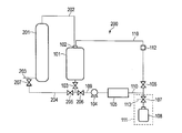
- FIG. 1 is a schematic diagram showing an embodiment of a manufacturing apparatus that can be used in a method for manufacturing a processing liquid according to an embodiment of the present invention.
- FIG. 2 is a schematic diagram showing another embodiment of a manufacturing apparatus that can be used in the method for manufacturing a processing liquid according to the embodiment of the present invention.
- the notation that does not indicate substitution and non-substitution includes not only a substituent but also a substituent.
- the “alkyl group” includes not only an alkyl group having no substituent (unsubstituted alkyl group) but also an alkyl group having a substituent (substituted alkyl group).
- active light beam or “radiation” in the present specification refers to, for example, an emission line spectrum of a mercury lamp, far ultraviolet rays represented by excimer laser, extreme ultraviolet (EUV) rays, X rays or electron rays ( Electron Beam (EB).
- light means actinic rays or radiation.
- exposure in the present specification is not limited to exposure with far-ultraviolet rays such as mercury lamps and excimer lasers, X-rays and EUV light, but also with particle beams such as electron beams and ion beams, unless otherwise specified. Drawing is also included in the exposure.
- (meth) acrylate means “at least one of acrylate and methacrylate”.
- (Meth) acrylic acid means “at least one of acrylic acid and methacrylic acid”.
- a numerical range expressed using “to” means a range including numerical values described before and after “to” as a lower limit value and an upper limit value.
- the “processing solution for semiconductor manufacturing” moves to the next step after the end of each step in the manufacturing process of the semiconductor device including the lithography step, the etching step, the ion implantation step, the peeling step, and the like.
- a processing liquid used for processing organic substances before specifically, a processing liquid used as a developer, a rinsing liquid, a pre-wet liquid, a stripping liquid, or the like.
- processing liquid for semiconductor production of the present invention is a compound (B) satisfying the following requirement (b) and a compound (B) satisfying the following requirement (a).
- the compound (A) is a main component contained in the treatment liquid of the present invention at a content of 90.0 to 99.99999 mass%, and the content is, for example, 99.999 to 99.999999999 mass%. It is preferably 99.9999 to 99.9999999% by mass.
- the treatment liquid of the present invention may be a combined system of the compound (A) and another compound.
- the content of the other compound is, for example, 0.01 to 5.00% by mass.
- 0.1 to 2.00% by mass is more preferable.
- examples of other compounds include dimethyl sulfoxide.
- the compound (B) is contained as an impurity, and the total content thereof is 10 ⁇ 10 to 0.1 mass% with respect to the total mass of the treatment liquid.
- the total content of the compound (B) is the content described in the requirement (b), that is, the compound (B) having a content in the range of 10 ⁇ 11 to 0.1 mass% is treated.
- one kind exists in the liquid it means the content of this one kind of compound (B).
- two or more types of compounds (B) satisfying the requirement of the content rate described in the requirement (b) are present, it means the total content rate of the two or more types of compounds (B).
- the content of the compound (B) described in the requirement (b) is preferably 10 ⁇ 10 to 10 ⁇ 4 mass%, more preferably 10 ⁇ 10 to 10 ⁇ 5 mass%.
- the inorganic substance (C) containing any element selected from Al, B, S, N and K is mixed during the synthesis of the treatment liquid of the present invention and is mainly derived from the catalyst.
- the treatment liquid of the present invention contains a compound containing any element selected from Al, B, and S as the inorganic substance (C).
- Compound (B) and inorganic substance (C) are mostly removed in the purification step of the treatment liquid, but remain slightly in the purified treatment liquid.
- the present invention was developed based on the knowledge that the ratio of the compound (B) and the inorganic substance (C) contained in the semiconductor manufacturing treatment liquid has a significant effect on the litho performance and defect performance,
- One of the characteristics is that the P value represented by the following formula I, which is the ratio of the inorganic substance (C) to the compound (B), is in the range of 10 3 to 10 ⁇ 6 .
- the P value represented by the formula I which is the ratio of the inorganic substance (C) to the compound (B), is preferably 10 3 to 10 ⁇ 5 , and more preferably 10 2 to 10 ⁇ 4 .
- the compound (B) is an impurity that is slightly contained in the range of 10 ⁇ 10 to 0.1 mass% in total with respect to the total mass of the treatment liquid, but the compound represented by the following formula II
- the ratio Q between (A) and the compound (B) is preferably 10 4 to 10 10 from the viewpoints of improving lithographic performance and suppressing defects.
- the Q value represented by formula II which is the ratio of compound (A) to compound (B), is more preferably from 10 5 to 10 10 , and even more preferably from 10 6 to 10 10 .
- the content of the inorganic substance (C) is preferably 0.0001 to 100 mass ppb (parts per billion), more preferably 0.001 to 100 mass ppb, based on the total mass of the treatment liquid.
- the content of each of the inorganic substances (C) is preferably 0.0001 to 100 mass ppb, preferably 0.001 to 100 mass ppb is more preferable.
- the concentration of each of the inorganic substances (C) is 100 mass ppb or less, it can be suppressed that these compounds remain on the substrate as a residual component nucleus during processing and cause defects.
- the inorganic substance (C) is removed from the substrate, it is presumed that it is removed as a certain mass of ions or compounds in such a manner that the compound (B) is involved. Therefore, when there are too few inorganic substances (C), the removal rate of an inorganic substance (C) and a compound (B) will deteriorate, and it will remain on a board
- the compound (A) contained in the treatment liquid of the present invention is a compound selected from an alcohol compound, a ketone compound and an ester compound as described above, and the treatment liquid of the present invention is one or more of these. Containing the compound.
- Examples of the alcohol compound include methanol, ethanol, 1-propanol, isopropanol, 1-butanol, 2-butanol, 3-methyl-1-butanol, tert-butyl alcohol, 1-pentanol, 2-pentanol, 1- Hexanol, 3-methyl-3-pentanol, cyclopentanol, 2,3-dimethyl-2-butanol, 3,3-dimethyl-2-butanol, 2-methyl-2-pentanol, 2-methyl-3- Pentanol, 3-methyl-2-pentanol, 3-methyl-3-pentanol, 4-methyl-2-pentanol, 4-methyl-3-pentanol, cyclohexanol, 3-methoxy-1-butanol, etc.
- Alcohol monohydric alcohol
- ethylene glycol diethylene glycol
- Glycol solvents such as ethylene glycol, ethylene glycol monomethyl ether, propylene glycol monomethyl ether (PGME; also known as 1-methoxy-2-propanol), diethylene glycol monomethyl ether, methoxymethyl butanol, ethylene glycol monoethyl ether, ethylene glycol monopropyl ether
- glycol ether solvents containing a hydroxyl group such as ethylene glycol monobutyl ether.
- ketone compound examples include acetone, 1-hexanone, 2-hexanone, cyclohexanone, methyl ethyl ketone, methyl isobutyl ketone, acetylacetone, acetonylacetone, acetylcarbinol, propylene carbonate, and ⁇ -butyrolactone.
- the ketone compound as the compound (A) includes a diketone compound.
- ester compound examples include methyl acetate, ethyl acetate, butyl acetate, isobutyl acetate, propyl acetate, isopropyl acetate, ethyl methoxyacetate, ethyl ethoxyacetate, propylene glycol monomethyl ether acetate (PGMEA; also known as 1-methoxy-2-acetoxypropane) ), Ethylene glycol monoethyl ether acetate, ethylene glycol monopropyl ether acetate, ethylene glycol monobutyl ether acetate, methyl formate, ethyl formate, butyl formate, propyl formate, ethyl lactate, propyl lactate, ethyl carbonate, propyl carbonate, butyl carbonate, pyruvin Methyl acetate, ethyl pyruvate, propyl pyruvate, methyl acetoacetate
- Compound (A) may be a mixture of compounds having different structures with the same carbon number, such as isomers, in one form.
- the compound of the said same carbon number and a different structure only 1 type may be contained and multiple types may be contained as mentioned above.
- the compound (A) has a flash point of preferably 80 ° C. or lower, more preferably 75 ° C. or lower, and further preferably 65 ° C. or lower. Further, the lower limit value of the flash point is not particularly limited, but is preferably 23 ° C. or higher, for example.
- the compound (B) contained in the treatment liquid of the present invention is a compound selected from an alcohol compound having 6 or more carbon atoms, a ketone compound, an ester compound, an ether compound, and an aldehyde compound.
- the liquid contains one or more of these compounds.
- the number of carbon atoms in the compound (B) is preferably 6-12, more preferably 6-10.
- the compound (B) is preferably at least one compound represented by the following formulas I to V.
- R 1 and R 2 each independently represents an alkyl group or a cycloalkyl group, or are bonded to each other to form a ring.
- an alkyl group having 1 to 12 carbon atoms and a cycloalkyl group having 6 to 12 carbon atoms are preferable, and an alkyl group having 1 to 8 carbon atoms, carbon A cycloalkyl group having a number of 6 to 8 is more preferable.
- the ring formed by combining R 1 and R 2 with each other is a lactone ring, more preferably a 4- to 9-membered lactone ring, and even more preferably a 4- to 6-membered lactone ring.
- R 1 and R 2 satisfy the relationship in which the compound represented by Formula I has 6 or more carbon atoms.
- R 3 and R 4 each independently represent a hydrogen atom, an alkyl group, an alkenyl group, a cycloalkyl group or a cycloalkenyl group, or are bonded to each other to form a ring. However, R 3 and R 4 are not both hydrogen atoms.
- alkyl group represented by R 3 and R 4 for example, an alkyl group having 1 to 12 carbon atoms is preferable, and an alkyl group having 1 to 8 carbon atoms is more preferable.
- alkenyl group represented by R 3 and R 4 for example, an alkenyl group having 2 to 12 carbon atoms is preferable, and an alkenyl group having 2 to 8 carbon atoms is more preferable.
- the cycloalkyl group represented by R 3 and R 4 is preferably a cycloalkyl group having 6 to 12 carbon atoms, and more preferably a cycloalkyl group having 6 to 8 carbon atoms.
- cycloalkenyl group represented by R 3 and R 4 for example, a cycloalkenyl group having 3 to 12 carbon atoms is preferable, and a cycloalkenyl group having 6 to 8 carbon atoms is more preferable.
- the ring formed by combining R 3 and R 4 with each other has a cyclic ketone structure, which may be a saturated cyclic ketone or an unsaturated cyclic ketone.
- the cyclic ketone is preferably a 6 to 10 membered ring, and more preferably a 6 to 8 membered ring.
- R 3 and R 4 satisfy the relationship in which the compound represented by Formula II has 6 or more carbon atoms.
- R 5 represents an alkyl group or a cycloalkyl group.
- the alkyl group represented by R 5 is an alkyl group having 6 or more carbon atoms, preferably an alkyl group having 6 to 12 carbon atoms, and more preferably an alkyl group having 6 to 10 carbon atoms.
- This alkyl group may have an ether bond in the chain, and may have a substituent such as a hydroxy group.
- the cycloalkyl group represented by R 5 is a cycloalkyl group having 6 or more carbon atoms, preferably a cycloalkyl group having 6 to 12 carbon atoms, and more preferably a cycloalkyl group having 6 to 10 carbon atoms.
- R 6 and R 7 each independently represents an alkyl group or a cycloalkyl group, or are bonded to each other to form a ring.
- alkyl group represented by R 6 and R 7 for example, an alkyl group having 1 to 12 carbon atoms is preferable. Further, an alkyl group having 1 to 8 carbon atoms is more preferable.
- the cycloalkyl group represented by R 6 and R 7 is preferably a cycloalkyl group having 6 to 12 carbon atoms, and more preferably a cycloalkyl group having 6 to 8 carbon atoms.
- the ring formed by combining R 6 and R 7 with each other is a cyclic ether structure.
- This cyclic ether structure is preferably a 4- to 8-membered ring, more preferably a 5- to 7-membered ring.
- R 6 and R 7 satisfy the relationship in which the compound represented by Formula IV has 6 or more carbon atoms.
- R 8 and R 9 each independently represents an alkyl group or a cycloalkyl group, or are bonded to each other to form a ring.
- L represents a single bond or an alkylene group.
- alkyl group represented by R 8 and R 9 for example, an alkyl group having 6 to 12 carbon atoms is preferable, and an alkyl group having 6 to 10 carbon atoms is more preferable.
- the cycloalkyl group represented by R 8 and R 9 is preferably a cycloalkyl group having 6 to 12 carbon atoms, and more preferably a cycloalkyl group having 6 to 10 carbon atoms.
- the ring formed by combining R 8 and R 9 with each other is a cyclic diketone structure.
- the cyclic diketone structure is preferably a 6-12 membered ring, more preferably a 6-10 membered ring.
- alkylene group represented by L for example, an alkylene group having 1 to 12 carbon atoms is preferable, and an alkylene group having 1 to 10 carbon atoms is more preferable.
- R 8 , R 9, and L satisfy the relationship in which the compound represented by Formula V has 6 or more carbon atoms.
- Specific examples of the compound (B) include the following compounds.
- the treatment liquid of the present invention contains Na, Ca and Fe, and the content of each atom is preferably in the range of 0.01 mass ppt to 1000 mass ppb.
- Na, Ca, and Fe are metal atoms mixed from various processes until the treatment liquid of the present invention is synthesized. When the concentration of each metal atom is 1000 mass ppb or less, it can be suppressed that these metal atoms remain on the substrate as a residual component nucleus during processing and cause defects.
- the content of each atom of Na, Ca and Fe contained in the treatment liquid is more preferably 0.01 mass ppt to 500 mass ppb, and still more preferably 0.05 mass ppt to 100 mass ppb.
- the treatment liquid of the present invention has a total content of metal particles as measured by the SNP-ICP-MS method (Single-Particle ICP-MS) based on the total mass of the treatment liquid of the present invention. 0.001 to 100 mass ppt is preferable, and 1 to 100 mass ppt is more preferable.
- Metal atoms contained as impurities in semiconductor processing liquids are one of the factors that cause defects in fine patterns and fine semiconductor elements. For this reason, it was thought that the smaller the amount of metal atoms contained in the semiconductor manufacturing treatment solution, the better. However, the present inventor has found that the amount of metal atoms contained in the treatment liquid does not necessarily correlate with the defect occurrence rate, and the defect occurrence rate varies.
- a metal particle is a metal component that does not dissolve in a solution and exists as a solid.
- the amount of metal atoms contained in a semiconductor manufacturing treatment solution or the like is usually analyzed by an ICP-MS method or the like, and depending on conventional methods such as the ICP-MS method, ions derived from metal atoms.
- the total mass of metal atoms that is, the total mass of ionic metal and particulate metal (non-ionic metal) (hereinafter referred to as “total metal amount”, etc.) cannot be distinguished from ionic metal and metal particles (non-ionic metal) Also quantified as).
- the inventor of the present invention has made it possible to identify and quantify by measurement using the SNP-ICP-MS method, ionic metal derived from metal atoms and metal particles (nonionic metal) contained in the treatment liquid We have studied earnestly about the effect of each of these on defects. As a result, it has been found that the amount of metal particles (nonionic metal) is extremely influenced by the occurrence of defects, and that there is a correlation between the amount of metal particles (nonionic metal) and the occurrence of defects. .
- the total content of metal particles as measured by the SNP-ICP-MS method is particularly preferably 1 to 50 mass ppt.
- an apparatus that can be used in the measurement using the SNP-ICP-MS method in addition to the apparatus used in the examples described later (NexION 350S manufactured by PerkinElmer), for example, Agilent 8800 Triple Quadrupole ICP- manufactured by Agilent Technologies, Inc. MS (inductively coupled plasma mass spectrometry, for semiconductor analysis, option # 200); Agilent Technologies, Inc., Agilent 8900, etc. are mentioned.
- a mixture of two or more of the above-described treatment liquids of the present invention may be used for various applications as the treatment liquid of the present invention.
- the treatment liquid of the present invention can be produced by a known method.
- the raw material is reacted in the presence of a catalyst to synthesize the compound (A) to obtain a crude liquid containing the compound (A), and the crude liquid is then purified by, for example, filtering described later. Is done.
- the catalyst can be appropriately selected depending on the compound (A).
- sulfuric acid HgSO 4 , NaNH 2 , Al (C 2 H 5 ) 3 , Ipc 2 BH (Diisopinocampheylborane)
- examples thereof include a solid catalyst containing copper oxide-zinc oxide, a supported phosphoric acid catalyst, and a supported copper catalyst.
- the method for producing a treatment liquid of the present invention preferably uses a compound containing at least one selected from Al, B, S, N and K as a catalyst.
- a compound containing at least one selected from Al, B, S, N and K is preferably used as a catalyst.
- the raw material used in the production of the treatment liquid of the present invention is preferably a material that has been purified in advance by distillation, ion exchange, filtration, or the like.
- the purity is 99% by mass or more, preferably 99.9% by mass or more. It is more preferable to use a raw material of a high purity grade, and it is particularly preferable to use it after further purification. The use of such a high-purity raw material is important in order to obtain a remarkable effect according to the present invention.
- the catalyst used in the process liquid production method of the present invention it is preferable to use a catalyst that has been purified in advance by distillation, ion exchange, filtration, or the like as the catalyst used in the process liquid production method of the present invention.
- the purity is 99% by mass or more, preferably 99.9% by mass or more, and a high-purity grade catalyst is preferable.
- FIG. 1 is a schematic view showing an embodiment of a manufacturing apparatus that can be used in a method for manufacturing a processing liquid according to an embodiment of the present invention.
- the manufacturing apparatus 100 includes a tank 101, and the tank 101 includes a supply port 102 for supplying a cleaning liquid and / or an organic solvent (a crude liquid containing the compound (A)) described later.
- the manufacturing apparatus 100 includes a filtration device 105.
- the tank 101 and the filtration device 105 are connected by a supply pipe 109, and a fluid (cleaning liquid, organic solvent, treatment liquid, etc.) is connected between the tank 101 and the filtration device 105. ) Can be transported.
- a valve 103 and a pump 104 are arranged in the supply line 109.
- the manufacturing apparatus 100 includes a tank 101 and a filtration device 105, but the manufacturing apparatus that can be used in the method for manufacturing a processing liquid according to the embodiment of the present invention is not limited thereto.
- the fluid supplied from the supply port 102 flows into the filtration device 105 through the valve 103 and the pump 104.
- the fluid discharged from the filtration device 105 is accommodated in the tank 101 via the circulation pipe 110.
- the manufacturing apparatus 100 includes a discharge unit 111 that discharges the processing liquid to the circulation line 110.
- the discharge part 1111 includes a valve 107 and a container 108, and the processing liquid produced can be accommodated in the container 108 by switching the valve 106 provided in the circulation line and the valve 107.
- a switchable pipe line 113 is connected to the valve 107, and the cleaning liquid after circulation cleaning can be discharged out of the manufacturing apparatus 100 through the pipe line 113.
- the cleaning liquid after the circulation cleaning may contain particles, metal impurities, and the like. According to the manufacturing apparatus 100 including the pipe 113 for discharging the cleaning liquid to the outside of the apparatus, the filling portion of the container 108 and the like It is possible to obtain a treatment liquid that is superior in defect suppression performance without being contaminated.
- the manufacturing apparatus 100 includes a cleaning liquid monitoring unit 112 in the circulation pipe 110.
- the manufacturing apparatus 100 includes the cleaning liquid monitoring unit 112 in the circulation pipe 110, but the manufacturing apparatus that can be used in the processing liquid manufacturing method according to the embodiment of the present invention is not limited thereto.
- the cleaning liquid monitoring unit 112 may be provided in the supply pipeline 109, or may be provided in the supply pipeline 109 and the circulation pipeline 110. In the manufacturing apparatus 100, the cleaning liquid monitoring unit 112 is directly provided in the circulation pipe 110.
- the manufacturing apparatus that can be used in the processing liquid manufacturing method according to the embodiment of the present invention is not limited thereto.
- the cleaning liquid monitoring unit may be provided in a temporary storage tank (not shown) of the fluid (not shown) provided in the pipeline.
- FIG. 2 is a schematic diagram showing another embodiment of a manufacturing apparatus that can be used in the method for manufacturing a processing liquid according to the embodiment of the present invention.
- the manufacturing apparatus 200 includes a tank 101 and a filtration device 105, and is further connected to the tank 101 with a pipe line 202, a pipe line 204, and a pipe line 203, and fluid between the tank 101 through each of the pipe lines. Is provided with a distillation column 201 arranged so that it can be transferred.
- the filtration apparatus 105 and / or the distillation column 201 do not necessarily need to be provided, Furthermore, a reaction vessel or the like connected to the distillation column 201 by a pipe line 203 may be provided.
- the fluid supplied to the distillation column 201 through the pipe line 203 is distilled in the distillation column 201.
- the distilled fluid is accommodated in the tank 101 via the pipe line 202.
- the supply pipe 109 is provided with a valve 103 and a valve 206, and the fluid discharged from the tank 101 can flow into the filtration device 105 by switching to the valve 205 provided in the pipe 204. ing.
- the fluid discharged from the tank 101 can also flow into the distillation column 201 again. In that case, the fluid flows into the distillation column 201 from the pipe line 204 through the valve 207 and the pipe line 203 by switching the valve 103, the valve 206, and the valve 205 described above.
- the material of the wetted part of the manufacturing apparatus (the definition of the wetted part will be described later) is not particularly limited, but a non-metallic material and electrolysis can be obtained in that a treatment liquid having better defect suppression performance can be obtained. It is preferably formed from at least one selected from the group consisting of polished metal materials.
- the “wetted part” is a part where the fluid may come into contact (for example, tank inner surface, liquid feed pump, damper, packing, O-ring, pipe inner surface, etc.), and A region of 100 nm thickness from the surface is intended.
- the non-metallic material is not particularly limited, but is preferably a polyethylene resin, a polypropylene resin, a polyethylene-polypropylene resin, and a fluorine-containing resin material, and is a fluorine-containing resin material from the viewpoint of less elution of metal atoms. preferable.
- fluorine-containing resin examples include perfluororesins, such as tetrafluoroethylene resin (PTFE), tetrafluoroethylene / perfluoroalkyl vinyl ether copolymer (PFA), and tetrafluoroethylene-hexafluoropropylene copolymer.
- PTFE tetrafluoroethylene resin
- PFA perfluoroalkyl vinyl ether copolymer
- FEP Polymerization resin
- ETFE Tetrafluoroethylene-ethylene copolymer resin
- ECTFE Trifluoroethylene chloride-ethylene copolymer resin
- PVDF Vinylidene fluoride resin
- PCTFE Trifluoroethylene chloride copolymer resin
- PVF vinyl fluoride resin
- fluorine-containing resins include tetrafluoroethylene resin, tetrafluoroethylene / perfluoroalkyl vinyl ether copolymer, and tetrafluoroethylene-hexafluoropropylene copolymer resin.
- the metal material is not particularly limited, and a known material can be used.
- the metal material include a metal material having a total content of chromium and nickel of more than 25% by mass with respect to the total mass of the metal material, and more preferably 30% by mass or more.
- the upper limit of the total content of chromium and nickel in the metal material is not particularly limited, but is generally preferably 90% by mass or less.
- the metal material include stainless steel, carbon steel, alloy steel, nickel chrome molybdenum steel, chrome steel, chrome molybdenum steel, manganese steel, and nickel-chromium alloy.
- Stainless steel is not particularly limited, and known stainless steel can be used. Especially, the alloy containing 8 mass% or more of nickel is preferable, and the austenitic stainless steel containing 8 mass% or more of nickel is more preferable.
- austenitic stainless steel for example, SUS (Steel Use Stainless) 304 (Ni content 8 mass%, Cr content 18 mass%), SUS304L (Ni content 9 mass%, Cr content 18 mass%), SUS316 ( Ni content 10 mass%, Cr content 16 mass%), SUS316L (Ni content 12 mass%, Cr content 16 mass%), etc. are mentioned.
- the nickel-chromium alloy is not particularly limited, and a known nickel-chromium alloy can be used. Among these, a nickel-chromium alloy having a nickel content of 40 to 75% by mass and a chromium content of 1 to 30% by mass is preferable.
- nickel-chromium alloy examples include Hastelloy (trade name, the same applies hereinafter), Monel (trade name, the same applies hereinafter), Inconel (product name, the same applies hereinafter), and the like. More specifically, Hastelloy C-276 (Ni content 63 mass%, Cr content 16 mass%), Hastelloy-C (Ni content 60 mass%, Cr content 17 mass%), Hastelloy C-22 ( Ni content 61 mass%, Cr content 22 mass%) etc. are mentioned. Further, the nickel-chromium alloy may further contain boron, silicon, tungsten, molybdenum, copper, cobalt, and the like in addition to the above-described alloy as necessary.
- the method for electropolishing the metal material is not particularly limited, and a known method can be used.
- a known method can be used.
- the methods described in JP-A-2015-227501, paragraphs 0011 to 0014 and JP-A-2008-264929, paragraphs 0036 to 0042 can be used.
- the metal material is electropolished so that the chromium content in the passive layer on the surface is higher than the chromium content in the parent phase. Therefore, from the distillation tower formed from the metal material whose wetted part is electropolished, it is difficult for metal impurities containing metal atoms to flow out into the organic solvent. It is estimated that can be obtained.
- the metal material may be buffed.
- the buffing method is not particularly limited, and a known method can be used.
- the size of the abrasive grains used for buffing finishing is not particularly limited, but is preferably # 400 or less in that the unevenness on the surface of the metal material tends to be smaller.
- the buffing is preferably performed before the electrolytic polishing.
- the wetted part is preferably formed from electropolished stainless steel in that a treatment liquid having better defect suppression performance can be obtained.
- the manufacturing apparatus includes a tank
- the liquid contact portion of the tank is formed of stainless steel that has been electropolished.
- the mass ratio of the Cr content to the Fe content in the wetted part (hereinafter, also referred to as “Cr / Fe”) is not particularly limited, but is generally preferably 0.5 to 4, and in particular, the treatment In the point which a metal impurity and / or an organic impurity do not elute more easily in a liquid, 0.5 and less than 3.5 are more preferable, and 0.7 or more and 3.0 or less are more preferable.
- the method for adjusting Cr / Fe in the metal material is not particularly limited.
- the metal material may be a metal material to which a coating technique is applied.
- Coating technology is roughly divided into three types: metal coating (various plating), inorganic coating (various chemical conversion treatment, glass, concrete, ceramics, etc.) and organic coating (rust preventive oil, paint, rubber, plastics, etc.). Any of these may be used.
- Preferable film technology includes surface treatment with a rust inhibitor oil, a rust inhibitor, a corrosion inhibitor, a chelate compound, a peelable plastic, and a lining agent.
- a corrosion inhibitor various chromate, nitrite, silicate, phosphate, carboxylic acid (oleic acid, dimer acid, naphthenic acid, etc.), carboxylic acid metal soap, sulfonate, amine salt And esters (glycerin esters and phosphate esters of higher fatty acids) and the like.
- the chelate compound include ethylene diantetraacetic acid, gluconic acid, nitrilotriacetic acid, hydroxyethyl ethyl orange amine triacetic acid, diethylene triamine pentaacetic acid and the like.
- the lining agent include a fluororesin lining agent. Particularly preferred is treatment with a phosphate or a fluororesin lining agent.
- the above manufacturing apparatus includes the filtration device 105, so that it is easy to obtain a treatment liquid having better defect suppression performance.
- limit especially as a filtration member which the filtration apparatus 105 contains, At least 1 sort (s) selected from the group which consists of a filter with a particle removal diameter of 20 nm or less and a metal ion adsorption filter is preferable, and a particle removal diameter is 20 nm or less. More preferably, the filter is a metal ion adsorption filter.
- a filter with a particle removal diameter of 20 nm or less has a function of efficiently removing particles with a diameter of 20 nm or more from an organic solvent or the like as a raw material of the treatment liquid.
- the particle removal diameter of the filter is preferably 1 to 15 nm, and more preferably 1 to 12 nm. When the particle removal diameter is 15 nm or less, finer particles can be removed, and when the particle removal diameter is 1 nm or more, the filtration efficiency is improved.
- the particle removal diameter means the minimum particle size that can be removed by the filter. For example, when the particle removal diameter of the filter is 20 nm, particles having a diameter of 20 nm or more can be removed.
- the filter material examples include nylons such as 6-nylon and 6,6-nylon, polyethylene, polypropylene, polystyrene, polyimide, polyamideimide, and fluororesin.
- the polyimide and / or the polyamideimide may have at least one selected from the group consisting of a carboxy group, a salt-type carboxy group, and an —NH— bond.
- fluororesin, polyimide and / or polyamideimide are excellent.
- 6-nylon and nylon such as 6,6-nylon are particularly preferable.
- the filtration device 105 may contain a plurality of the above filters.
- the other filter is not particularly limited, but a filter having a particle removal diameter of 50 nm or more (for example, a microfiltration membrane for removing fine particles having a pore diameter of 50 nm or more) is preferable. .
- a filter having a particle removal diameter of 20 nm or less for example, Before filtration using a microfiltration membrane having a pore diameter of 20 nm or less, the material to be purified is filtered using a filter having a particle removal diameter of 50 nm or more (for example, a microfiltration membrane for removing fine particles having a pore diameter of 50 nm or more).
- a filter having a particle removal diameter of 20 nm or less for example, a microfiltration membrane having a pore diameter of 20 nm or less
- the particle removal performance is further improved.
- the said filtration apparatus 105 contains a metal ion adsorption filter. It does not restrict
- the metal ion adsorption filter an ion exchangeable filter is preferable.
- the metal ions to be adsorbed are not particularly limited, but contain one kind selected from the group consisting of Fe, Cr, Ni, and Pb because they are likely to cause defects in semiconductor devices. Metal ions are preferred, and metal ions containing Fe, Cr, Ni, and Pb, respectively, are preferred.
- the metal ion adsorption filter preferably contains an acid group on the surface from the viewpoint of improving the adsorption performance of metal ions.
- the acid group include a sulfo group and a carboxy group.
- Examples of the base material (material) constituting the metal ion adsorption filter include cellulose, diatomaceous earth, nylon, polyethylene, polypropylene, polystyrene, and fluororesin. Nylon is particularly preferable from the viewpoint of the efficiency of adsorbing metal ions.
- the metal ion adsorption filter may be made of a material containing polyimide and / or polyamideimide.
- Examples of the metal ion adsorption filter include a polyimide and / or polyamideimide porous membrane described in JP-A-2016-155121 (JP 2016-155121).
- the polyimide and / or polyamideimide porous membrane may contain at least one selected from the group consisting of a carboxy group, a salt-type carboxy group, and an —NH— bond.
- the metal ion adsorption filter is made of fluororesin, polyimide, and / or polyamideimide, it has better solvent resistance.
- the filtration apparatus 105 may further contain an organic impurity adsorption filter. It does not restrict
- an organic impurity adsorption filter has an organic skeleton capable of interacting with organic impurities on the surface in terms of improving the adsorption performance of organic impurities (in other words, the surface by an organic skeleton capable of interacting with organic impurities. Is preferably modified).
- Examples of the organic skeleton capable of interacting with the organic impurities include a chemical structure that can react with the organic impurities and trap the organic impurities in the organic impurity adsorption filter. More specifically, when n-long chain alkyl alcohol (structural isomer when 1-long chain alkyl alcohol is used as the organic solvent) is included as the organic impurity, the organic skeleton includes an alkyl group. . When dibutylhydroxytoluene (BHT) is included as an organic impurity, the organic skeleton includes a phenyl group.
- BHT dibutylhydroxytoluene
- Examples of the base material (material) constituting the organic impurity adsorption filter include cellulose, diatomaceous earth, nylon, polyethylene, polypropylene, polystyrene, and fluororesin that support activated carbon.
- organic impurity adsorption filter a filter in which activated carbon described in JP-A-2002-273123 and JP-A-2013-150979 is fixed to a nonwoven fabric can be used.
- organic impurity adsorption filter As the organic impurity adsorption filter, a physical adsorption method can be applied in addition to the chemical adsorption described above (adsorption using an organic impurity adsorption filter having an organic substance skeleton capable of interacting with organic impurities on the surface).
- the filtering by the first filter may be performed only once or may be performed twice or more.
- the filters may be of the same type or of different types, but of different types. It is preferable.
- the first filter and the second filter are preferably different in at least one of the hole diameter and the constituent material.
- the second and subsequent hole diameters are the same or smaller than the first filtering hole diameter.
- the pore diameter here can refer to the nominal value of the filter manufacturer. As a commercially available filter, it can select from the various filters which Nippon Pole Co., Ltd., Advantech Toyo Co., Ltd., Japan Integris Co., Ltd. (former Japan Microlith Co., Ltd.), KITZ micro filter, etc. provide, for example.
- P-nylon filter (pore size 0.02 ⁇ m, critical surface tension 77 mN / m) made of polyamide; (manufactured by Nippon Pole Co., Ltd.), “PE / clean filter (pore size 0.02 ⁇ m)” made of high-density polyethylene; (Manufactured by Nippon Pole Co., Ltd.) and “PE / clean filter (pore diameter 0.01 ⁇ m)” made by high-density polyethylene (made by Nippon Pole Co., Ltd.) can also be used.
- the method for manufacturing a treatment liquid according to an embodiment of the present invention may include a step of cleaning the manufacturing apparatus using a cleaning liquid.
- the cleaning liquid is supplied from the supply port 102 of the tank 101.
- the supply amount of the cleaning liquid is not particularly limited, an amount that can sufficiently clean the liquid contact portion of the tank 101 is preferable, and the volume of the cleaning liquid supplied is preferably 30% by volume or more with respect to the capacity of the tank 101.
- the valve 103 may be closed or open. However, when supplying the cleaning liquid from the supply port 102, the valve 103 is closed because the tank 101 can be easily cleaned. It is preferable.
- the cleaning liquid supplied to the tank 101 may be immediately transferred through the manufacturing apparatus, or may be transferred through the manufacturing apparatus (for example, through the supply line 109) after cleaning the tank 101.
- the method for cleaning the inside of the tank 101 using the cleaning liquid is not particularly limited, and examples thereof include a method for cleaning by rotating a stirring blade (not shown) provided in the tank 101.
- the time for cleaning the tank with the cleaning liquid is not particularly limited, and may be appropriately selected according to the material of the liquid contact portion of the tank 101, the type of processing liquid to be manufactured, the possibility of contamination, and the like. Generally, about 0.1 second to 48 hours is preferable.
- the cleaning liquid after cleaning may be discharged from a discharge port (not shown) provided at the bottom of the tank.
- a method for cleaning the supply pipe 109 of the manufacturing apparatus 100 using the cleaning liquid is not particularly limited, but the valve 103 and the valve 106 are opened, the valve 107 is closed, the pump 104 is operated, and the cleaning liquid is cleaned. Is preferably circulated in the production apparatus through the supply line 109 and the circulation line 110 (hereinafter also referred to as “circulation cleaning”).
- circulation cleaning preferably circulated in the production apparatus through the supply line 109 and the circulation line 110
- the cleaning method is more preferably circulating cleaning.
- An example of circulating cleaning will be described with reference to FIG.
- the cleaning liquid supplied from the tank 101 through the valve 103 into the manufacturing apparatus returns to the tank 101 through the supply pipe 109 (through the filtration device 105, the circulation pipe 110, and the valve 106) (circulation). To do).
- the cleaning liquid is filtered by the filtration device 105, and particles and the like dissolved and dispersed in the cleaning liquid are removed, so that the cleaning effect can be further enhanced.
- the valve 103 and the valve 107 are opened, the valve 106 is closed, the pump 104 is operated, and the cleaning liquid supplied from the supply port 102 of the tank 101 into the manufacturing apparatus is supplied.
- a method of discharging the cleaning liquid to the outside of the manufacturing apparatus through the valve 107 without circulating the cleaning liquid (hereinafter referred to as “batch cleaning” in this specification). May also be used.
- the cleaning liquid may be intermittently supplied into the manufacturing apparatus or may be continuously supplied into the manufacturing apparatus.
- cleaning solution there is no particular limitation on the cleaning liquid used when cleaning in advance as described above, and a known cleaning liquid can be used.
- the cleaning liquid may have, for example, water, alkylene glycol monoalkyl ether carboxylate, alkylene glycol monoalkyl ether, alkyl lactate ester, alkyl alkoxypropionate, cyclic lactone (preferably having 4 to 10 carbon atoms), or a ring.
- alkylene glycol monoalkyl ether carboxylate alkylene glycol monoalkyl ether
- alkyl lactate ester alkyl alkoxypropionate
- cyclic lactone preferably having 4 to 10 carbon atoms
- Examples thereof include monoketone compounds (preferably having 4 to 10 carbon atoms), alkylene carbonates, alkyl alkoxyacetates, and alkyl pyruvates.
- cleaning liquid for example, those described in JP-A-2016-57614, JP-A-2014-219664, JP-A-2016-138219, and JP-A-2015-135379 may be used. .
- PGME propylene glycol monomethyl ether
- CyPe cyclopentanone
- CyPn cyclopentanone
- nBA butyl acetate
- PGMEA propylene glycol monomethyl ether acetate
- CyHx cyclohexanone
- EL ethyl lactate
- HBM methyl 2-hydroxyisobutyrate
- DBCPN cyclopentanone dimethyl acetal
- GBL ⁇ -butyrolactone
- DMSO dimethyl sulfoxide
- EC ethylene carbonate
- PC propylene carbonate
- NMP 1- At least selected from the group consisting of methyl-2-pyrrolidone), iAA (isoamyl acetate), IPA (isopropanol), MEK (methyl ethyl ketone), and MIBC (4-methyl-2-pentanol).
- 1 type is preferably contained, and contains at least one selected from the group consisting of PGMEA, NMP, PGME, nBA, PC, CyHx, GBL, MIBC, EL, DMSO, iAA, MEK, PC, and CyPe More preferably, it comprises at least one selected from the group consisting of PGMEA, NMP, PGME, nBA, PC, CyHx, GBL, MIBC, EL, DMSO, iAA, MEK, PC, and CyPe preferable.
- cleaning liquid may be used individually by 1 type, or may use 2 or more types together. Further, the treatment liquid of the present invention may be used as a cleaning liquid.
- the treatment liquid of the present invention preferably has an ion concentration of 1 ppm (parts per million) or less, such as Cr, Co, Cu, Pb, Li, Mg, Mn, Ni, K, Ag, and Zn.
- ppm parts per million
- the following is more preferable.
- it is more preferably in the order of ppt (all the above concentrations are based on mass), and it is particularly preferable that the concentration is not substantially contained.
- the adjustment of the metal content in the treatment liquid of the present invention is performed by, for example, distillation or filter filtration in at least one of the raw material stage used when the treatment liquid is produced and the stage after the treatment liquid is prepared.
- filtration using an ion exchange resin, adsorption purification, and the like may be repeated and sufficiently purified.
- the method for adjusting the metal content rate (hereinafter, also referred to as “metal concentration reducing method”) is not particularly limited, but silicon carbide described in International Publication No. WO12 / 043396 is used. Adsorption purification etc. are mentioned, Furthermore, the example which combines distillation, some filter filtration, and filtration using ion exchange resin, and fully refine
- the method for adjusting the metal content is particularly preferably performed at the stage of raw materials used when producing the treatment liquid from the viewpoint of obtaining the effects of the present invention. Moreover, it is preferable to use a raw material of a grade in which specific metal atoms or inorganic ions such as sulfate ions, chloride ions, or nitrate ions, and metal ions described later are reduced.
- a “container” for containing raw materials used for the production of a treatment liquid As other methods related to the method for reducing the metal concentration, as a “container” for containing raw materials used for the production of a treatment liquid, the elution of impurities as described for a container for containing the treatment liquid of the present invention described later is performed. It is mentioned to use few containers.
- the process liquid of this invention does not contain a coarse particle substantially.
- the coarse particles contained in the treatment liquid are particles such as dust, dust, organic solids and inorganic solids contained as impurities in the raw material, and dust, dust and organics brought in as contaminants during the preparation of the treatment liquid. Examples of the particles include solids and inorganic solids, which finally exist as particles without being dissolved in the treatment liquid.
- the amount of coarse particles present in the treatment liquid can be measured in a liquid phase using a commercially available measuring apparatus in a light scattering type in-liquid particle measurement method using a laser as a light source.
- the treatment liquid of the present invention may be a kit for separately adding other raw materials.
- a solvent such as water or an organic solvent
- other compounds can be mixed and used depending on the application.
- the solvent that can be used at this time is such that each content of Na, Ca, or Fe contained in the solvent is within the specific value range of the present invention described above. The desired effect of the present invention is remarkably obtained.
- the treatment liquid of the present invention can be stored, transported and used in any container as long as corrosivity does not matter (whether or not it is a kit).
- a container a container having a high cleanliness and a small amount of impurity elution is preferable for semiconductor applications.
- the containers that can be used include, but are not limited to, “Clean Bottle” series manufactured by Aicero Chemical Co., Ltd., “Pure Bottle” manufactured by Kodama Resin Co., Ltd., and the like.
- the liquid contact part of the container is formed of a non-metallic material or stainless steel.
- the non-metallic material include materials exemplified as the non-metallic material used in the liquid contact part of the distillation column described above.
- an ethylene or propylene oligomer is used compared to using a container having a wetted part made of polyethylene resin, polypropylene resin, or polyethylene-polypropylene resin. Occurrence of the problem of elution can be suppressed.
- the liquid contact part is made of a fluororesin
- FluoroPure PFA composite drum manufactured by Entegris may be mentioned.
- the containers described in, for example, page 4 of Japanese Patent Publication No. 3-502677, page 3 of International Publication No. 2004/016526, and pages 9 and 16 of International Publication No. 99/46309 Can also be used.
- the liquid contact portion that comes into contact with the treatment liquid is preferably formed from stainless steel, and more preferably formed from stainless steel that has been electropolished.
- impurity metals and / or organic impurities are less likely to elute in the processing liquid stored in the container.
- the form of the stainless steel is as already described as the material of the wetted part of the distillation tower. The same applies to electropolished stainless steel.
- the Cr / Fe ratio in the stainless steel forming the wetted part of the container is as already described as the Cr / Fe ratio of the wetted part of the tank.
- These containers are preferably cleaned inside the container before filling.
- cleaning is not specifically limited, It is preferable that a metal content rate is less than 0.001 mass ppt (partsperper trillion).
- other organic solvents are refined to have the metal content within the above range, or the treatment liquid of the present invention or the treatment liquid of the present invention is diluted depending on the application. The effect of the present invention is remarkably obtained when the liquid contains at least one compound added to the treatment liquid of the present invention or the treatment liquid of the present invention.
- the above processing solution may be transported and stored by bottling into a container such as a gallon bottle or a coated bottle after manufacture.
- a container such as a gallon bottle or a coated bottle after manufacture.
- the gallon bottle may be one using a glass material or the other.
- the inside of the container may be replaced with an inert gas (such as nitrogen or argon) having a purity of 99.99995 volume% or more.
- an inert gas such as nitrogen or argon
- a gas having a low moisture content is preferable.
- the temperature may be normal temperature, but the temperature may be controlled in the range of ⁇ 20 ° C. to 30 ° C. in order to prevent deterioration.
- Water used in connection with the present invention for example, water that can be used in the process for producing the treatment liquid of the present invention, water that can be used in the pattern formation process of the present invention, and cleaning of the container for the treatment liquid of the present invention
- the water that can be used and the water that can be used for the measurement of the components of the treatment liquid of the present invention and the evaluation of the defect suppression performance and the litho performance related to the effects of the present invention should be ultrapure water used in semiconductor manufacturing. Is preferred.
- the purification method is not particularly limited, but purification using a filtration membrane or ion exchange membrane or purification by distillation is preferred. Further, for example, it is preferable to perform purification by the method described in JP-A-2007-254168.
- these waters preferably have a metal content of less than 0.001 mass ppt (parts per trillion).
- the treatment liquid of the present invention is preferably used for semiconductor production.
- an organic substance is processed after the end of each process or before moving to the next process.
- it is preferably used as a pre-wet liquid, a developer, a rinse liquid, a stripping liquid, and the like.
- a pre-wet liquid a developer, a rinse liquid, a stripping liquid, and the like.
- it can be used for rinsing edge-alignment of a semiconductor substrate before and after resist application.
- processing liquid can also be used as a cleaning liquid for an apparatus for manufacturing various processing liquids used for semiconductor manufacturing.
- the said process liquid can be used also as a dilution liquid of resin contained in a resist liquid (after-mentioned). That is, it can also be used as a solvent contained in an actinic ray-sensitive or radiation-sensitive composition.
- the said process liquid can be used suitably also for uses other than the object for semiconductor manufacture, and can also be used as developing solutions, such as a polyimide, a resist for sensors, a resist for lenses, and a rinse liquid.
- the treatment liquid can also be used as a solvent for medical use or cleaning use. In particular, it can be suitably used for cleaning containers, piping, substrates (for example, wafers, glass, etc.) and the like.
- the processing liquid of the present invention is basically a processing liquid used as a developing solution, a rinsing liquid, a pre-wet liquid, a peeling, etc. in a semiconductor device manufacturing method, and in one aspect, included in the semiconductor device manufacturing method. In the pattern forming method to be used, it is preferably used as a developing solution, a rinsing solution or a prewetting solution.
- an actinic ray-sensitive or radiation-sensitive composition (hereinafter also referred to as “resist composition”) is applied to a substrate and an actinic ray-sensitive or radiation-sensitive film (hereinafter “resist film”).
- resist composition an actinic ray-sensitive or radiation-sensitive composition
- resist film an actinic ray-sensitive or radiation-sensitive film
- a resist film forming process for forming the resist film, an exposure process for exposing the resist film, a substrate before the resist composition is applied, or the exposed resist film is processed with the above-described processing liquid. Processing steps.
- the processing solution of the present invention may be used as any one of a developing solution, a rinsing solution, and a prewetting solution, and is used as any two of the developing solution, the rinsing solution, and the prewetting solution. It is preferable to use it as a developer, a rinse solution and a pre-wet solution.
- a prewetting liquid is applied in advance on a substrate in order to improve the coating property before the step of forming a resist film using an actinic ray-sensitive or radiation-sensitive composition.
- a wet process may be included.
- the pre-wet process is described in JP 2014-220301 A, and these are incorporated.
- the resist film forming step is a step of forming a resist film using an actinic ray-sensitive or radiation-sensitive composition, and can be performed, for example, by the following method.
- each component described later is dissolved in a solvent and activated.
- a light-sensitive or radiation-sensitive composition is prepared, filtered as necessary, and then applied onto a substrate.
- the filter is preferably made of polytetrafluoroethylene, polyethylene, or nylon having a pore size of 0.1 ⁇ m or less, more preferably 0.05 ⁇ m or less, and still more preferably 0.03 ⁇ m or less.
- the actinic ray-sensitive or radiation-sensitive composition is applied to a substrate (eg, silicon or silicon dioxide coating) used for manufacturing an integrated circuit element by an appropriate application method such as a spinner. Thereafter, it is dried to form a resist film. If necessary, various base films (inorganic films, organic films, antireflection films) may be formed under the resist film.
- a substrate eg, silicon or silicon dioxide coating
- an appropriate application method such as a spinner.
- Heating can be performed by means provided in a normal exposure / developing machine, and may be performed using a hot plate or the like.
- the heating temperature is preferably 80 to 180 ° C, more preferably 80 to 150 ° C, still more preferably 80 to 140 ° C, and particularly preferably 80 to 130 ° C.
- the heating time is preferably 30 to 1000 seconds, more preferably 60 to 800 seconds, and even more preferably 60 to 600 seconds.
- the film thickness of the resist film is generally 200 nm or less, preferably 100 nm or less.
- the thickness of the formed resist film is preferably 50 nm or less. If the film thickness is 50 nm or less, pattern collapse is less likely to occur when a development process described later is applied, and better resolution performance is obtained.
- the film thickness ranges from 15 nm to 45 nm. If the film thickness is 15 nm or more, sufficient etching resistance can be obtained. More preferably, the film thickness ranges from 15 nm to 40 nm. When the film thickness is within this range, etching resistance and better resolution performance can be satisfied at the same time.
- an upper layer film may be formed on the upper layer of the resist film.
- the upper film can be formed using, for example, an upper film forming composition containing a hydrophobic resin, an acid generator, and a basic compound.
- the upper layer film and the composition for forming the upper layer film are as described below.
- An exposure process is a process of exposing the said resist film, for example, can be performed with the following method.
- the resist film formed as described above is irradiated with actinic rays or radiation through a predetermined mask. Note that in electron beam irradiation, drawing (direct drawing) without using a mask is common.
- the actinic ray or radiation is not particularly limited, and examples thereof include a KrF excimer laser, an ArF excimer laser, EUV light (Extreme Ultra Violet), and an electron beam (EB, Electron Beam).
- the exposure may be immersion exposure.
- baking is preferably performed after exposure and before development.
- the reaction of the exposed part is promoted by baking, and the sensitivity and pattern shape become better.
- the heating temperature is preferably 80 to 150 ° C, more preferably 80 to 140 ° C, and still more preferably 80 to 130 ° C.
- the heating time is preferably 30 to 1000 seconds, more preferably 60 to 800 seconds, and even more preferably 60 to 600 seconds. Heating can be performed by means provided in a normal exposure / developing machine, and may be performed using a hot plate or the like.
- the development step is a step of developing the exposed resist film with a developer.
- a developing method for example, a method in which a substrate is immersed in a tank filled with a developer for a certain period of time (dip method), a method in which the developer is raised on the surface of the substrate by surface tension and is left stationary for a certain time (paddle) Method), a method of spraying the developer on the substrate surface (spray method), a method of continuously discharging the developer while scanning the developer discharge nozzle on the substrate rotating at a constant speed (dynamic dispensing method) Etc.
- dip method a method in which a substrate is immersed in a tank filled with a developer for a certain period of time
- paddle a method in which the developer is raised on the surface of the substrate by surface tension and is left stationary for a certain time
- spray method a method of spraying the developer on the substrate surface
- the development time is not particularly limited as long as the resin in the unexposed area is sufficiently dissolved, and is usually 10 to 300 seconds, preferably 20 to 120 seconds.
- the temperature of the developer is preferably 0 to 50 ° C, more preferably 15 to 35 ° C.
- As the developer used in the development step it is preferable to use the above-described processing solution.
- the developer is as described above. In addition to development using a processing solution, development with an alkaline developer may be performed (so-called double development).
- the rinsing step is a step of washing (rinsing) with a rinsing liquid after the developing step.
- the developed wafer is cleaned using the rinsing liquid.
- the method of the cleaning process is not particularly limited.
- a method of continuously discharging the rinse liquid onto the substrate rotating at a constant speed (rotary discharge method), or immersing the substrate in a tank filled with the rinse liquid for a certain period of time.
- a method (dip method), a method of spraying a rinsing liquid onto the substrate surface (spray method), and the like can be applied.
- a cleaning process is performed by a rotary discharge method, and after cleaning, the substrate is rotated at a speed of 2000 rpm to 4000 rpm. It is preferable to rotate and remove the rinse liquid from the substrate.
- the rinsing time is not particularly limited, but is usually 10 to 300 seconds.
- the time is preferably 10 seconds to 180 seconds, and most preferably 20 seconds to 120 seconds.
- the temperature of the rinse liquid is preferably 0 to 50 ° C., more preferably 15 to 35 ° C. Further, after the developing process or the rinsing process, a process of removing the developing solution or the rinsing liquid adhering to the pattern with a supercritical fluid can be performed.
- the heating temperature is not particularly limited as long as a good resist pattern can be obtained, and is usually 40 to 160 ° C.
- the heating temperature is preferably 50 to 150 ° C, and most preferably 50 to 110 ° C.
- the heating time is not particularly limited as long as a good resist pattern can be obtained, but it is usually 15 to 300 seconds, and preferably 15 to 180 seconds.
- the rinse liquid it is preferable to use the above-described treatment liquid.
- the explanation of the rinse liquid is as described above.
- any one of the developer, the rinsing liquid, and the pre-wet liquid may be the processing liquid of the present invention described above. These two may be the processing solution of the present invention, and three of the developing solution, the rinsing solution and the prewetting solution may be the processing solution of the present invention.
- the treatment liquid used in the pattern forming method of the present invention and the actinic ray-sensitive or radiation-sensitive resin composition preferably satisfy the following relationship in one embodiment. That is, the dissolution rate of the actinic ray-sensitive or radiation-sensitive film formed using the actinic ray-sensitive or radiation-sensitive resin composition in the treatment liquid of the present invention is 0.0016 to 0.33 nm / second. It is preferable to use the actinic ray-sensitive or radiation-sensitive resin composition that satisfies a certain relationship and the treatment liquid of the present invention.
- the dissolution rate of the actinic ray-sensitive or radiation-sensitive film in the treatment liquid of the present invention is a film when the actinic ray-sensitive or radiation-sensitive film is formed and then immersed in the treatment liquid of the present invention. This is the rate of decrease in thickness, and in the present invention, it is the dissolution rate at 23 ° C.
- the dissolution rate is more preferably 0.0016 to 0.16 nm / second, and further preferably 0.0016 to 0.08 nm / second.
- Resin (A) Resin
- the actinic ray-sensitive or radiation-sensitive composition preferably used in combination with the treatment liquid of the present invention preferably contains a resin (A).
- Resin (A) is at least (i) a repeating unit having a group that decomposes by the action of an acid to generate a carboxyl group (may further have a repeating unit having a phenolic hydroxyl group), or at least (ii) It has a repeating unit having a phenolic hydroxyl group.
- Examples of the repeating unit having a phenolic hydroxyl group contained in the resin (A) include a repeating unit represented by the following general formula (I).
- R 41 , R 42 and R 43 each independently represents a hydrogen atom, an alkyl group, a halogen atom, a cyano group or an alkoxycarbonyl group.
- R 42 may form a ring with Ar 4, R 42 in this case represents a single bond or an alkylene group.
- X 4 represents a single bond, —COO—, or —CONR 64 —, and R 64 represents a hydrogen atom or an alkyl group.
- L 4 represents a single bond or an alkylene group.
- Ar 4 represents an (n + 1) -valent aromatic ring group, and when bonded to R 42 to form a ring, represents an (n + 2) -valent aromatic ring group.
- n represents an integer of 1 to 5.
- the alkyl group represented by R 41 , R 42 and R 43 in the general formula (I) is preferably a methyl group, ethyl group, propyl group, isopropyl group, n-butyl group, sec- Examples thereof include alkyl groups having 20 or less carbon atoms such as butyl group, hexyl group, 2-ethylhexyl group, octyl group and dodecyl group, more preferably alkyl groups having 8 or less carbon atoms, particularly preferably alkyl groups having 3 or less carbon atoms. Can be mentioned.
- the cycloalkyl group represented by R 41 , R 42 and R 43 in the general formula (I) may be monocyclic or polycyclic.
- Preferred examples include a monocyclic cycloalkyl group having 3 to 8 carbon atoms such as a cyclopropyl group, a cyclopentyl group, and a cyclohexyl group, which may have a substituent.
- Examples of the halogen atom of R 41 , R 42 and R 43 in the general formula (I) include a fluorine atom, a chlorine atom, a bromine atom and an iodine atom, and a fluorine atom is particularly preferable.
- alkyl group contained in the alkoxycarbonyl group of R 41 , R 42 and R 43 in the general formula (I) the same alkyl groups as those described above for R 41 , R 42 and R 43 are preferable.
- Preferred substituents in each of the above groups include, for example, alkyl groups, cycloalkyl groups, aryl groups, amino groups, amide groups, ureido groups, urethane groups, hydroxyl groups, carboxyl groups, halogen atoms, alkoxy groups, thioether groups, acyls. Groups, acyloxy groups, alkoxycarbonyl groups, cyano groups, nitro groups and the like, and the substituent preferably has 8 or less carbon atoms.
- Ar 4 represents an (n + 1) -valent aromatic ring group.
- the divalent aromatic ring group in the case where n is 1 may have a substituent, for example, an arylene group having 6 to 18 carbon atoms such as a phenylene group, a tolylene group, a naphthylene group, an anthracenylene group, or the like.
- Examples of preferred aromatic ring groups include heterocycles such as thiophene, furan, pyrrole, benzothiophene, benzofuran, benzopyrrole, triazine, imidazole, benzimidazole, triazole, thiadiazole, thiazole.
- n + 1) -valent aromatic ring group in the case where n is an integer of 2 or more include (n-1) arbitrary hydrogen atoms removed from the above-described specific examples of the divalent aromatic ring group.
- the group formed can be preferably mentioned.
- the (n + 1) -valent aromatic ring group may further have a substituent.
- Examples of the substituent that the above-described alkyl group, cycloalkyl group, alkoxycarbonyl group, alkylene group, and (n + 1) -valent aromatic ring group may have include R 41 , R 42 , and R 43 in formula (I).
- Examples include alkyl groups such as alkyl groups, methoxy groups, ethoxy groups, hydroxyethoxy groups, propoxy groups, hydroxypropoxy groups, and butoxy groups; aryl groups such as phenyl groups; and the like.
- R 64 represents a hydrogen atom, an alkyl group
- the alkyl group for R 64 in, preferably an optionally substituted methyl group, an ethyl group, a propyl group , An isopropyl group, an n-butyl group, a sec-butyl group, a hexyl group, a 2-ethylhexyl group, an octyl group, a dodecyl group, and the like, and an alkyl group having a carbon number of 8 or less is more preferable.
- X 4 is preferably a single bond, —COO— or —CONH—, and more preferably a single bond or —COO—.
- the alkylene group for L 4 is preferably an alkylene group having 1 to 8 carbon atoms such as an optionally substituted methylene group, ethylene group, propylene group, butylene group, hexylene group and octylene group.
- an optionally substituted aromatic ring group having 6 to 18 carbon atoms is more preferable, and a benzene ring group, a naphthalene ring group, and a biphenylene ring group are particularly preferable.
- the repeating unit represented by the general formula (I) preferably has a hydroxystyrene structure. That is, Ar 4 is preferably a benzene ring group.
- Preferred examples of the repeating unit having a phenolic hydroxyl group that the resin (A) has include a repeating unit represented by the following general formula (p1).
- R represents a hydrogen atom, a halogen atom or a linear or branched alkyl group having 1 to 4 carbon atoms. A plurality of R may be the same or different. As R in the general formula (p1), a hydrogen atom is particularly preferable.
- Ar in the general formula (p1) represents an aromatic ring, for example, an aromatic carbon which may have a substituent having 6 to 18 carbon atoms such as a benzene ring, a naphthalene ring, an anthracene ring, a fluorene ring, a phenanthrene ring.
- a hydrogen ring or a heterocycle such as a thiophene ring, furan ring, pyrrole ring, benzothiophene ring, benzofuran ring, benzopyrrole ring, triazine ring, imidazole ring, benzimidazole ring, triazole ring, thiadiazole ring, thiazole ring, etc.
- aromatic ring heterocycles is especially, a benzene ring is most preferable.
- M in the general formula (p1) represents an integer of 1 to 5, preferably 1.
- the content of the repeating unit having a phenolic hydroxyl group is preferably from 0 to 50 mol%, more preferably from 0 to 45 mol%, still more preferably from 0 to 40 mol%, based on all repeating units in the resin (A). is there.
- the repeating unit having a group that decomposes by the action of an acid and generates a carboxyl group in the resin (A) is a repeating unit having a group in which a hydrogen atom of the carboxyl group is substituted with a group that decomposes and leaves by the action of an acid It is.
- Examples of the group leaving with an acid include —C (R 36 ) (R 37 ) (R 38 ), —C (R 36 ) (R 37 ) (OR 39 ), —C (R 01 ) (R 02 ). ) (OR 39 ) and the like.
- R 36 to R 39 each independently represents an alkyl group, a cycloalkyl group, an aryl group, an aralkyl group or an alkenyl group.
- R 36 and R 37 may be bonded to each other to form a ring.
- R 01 and R 02 each independently represents a hydrogen atom, an alkyl group, a cycloalkyl group, an aryl group, an aralkyl group or an alkenyl group.
- the resin (A) is preferably a repeating unit represented by the following general formula (AI).
- Xa 1 represents a hydrogen atom or an alkyl group which may have a substituent.
- T represents a single bond or a divalent linking group.
- Rx 1 to Rx 3 each independently represents an alkyl group (straight or branched) or a cycloalkyl group (monocyclic or polycyclic). However, when all of Rx 1 to Rx 3 are alkyl groups (linear or branched), at least two of Rx 1 to Rx 3 are preferably methyl groups. Two of Rx 1 to Rx 3 may combine to form a cycloalkyl group (monocyclic or polycyclic).
- Examples of the optionally substituted alkyl group represented by Xa 1 include a methyl group or a group represented by —CH 2 —R 11 .
- R 11 represents a halogen atom (such as a fluorine atom), a hydroxyl group or a monovalent organic group, and examples thereof include an alkyl group having 5 or less carbon atoms and an acyl group having 5 or less carbon atoms, preferably 3 or less carbon atoms. And more preferably a methyl group.
- Xa 1 is preferably a hydrogen atom, a methyl group, a trifluoromethyl group, a hydroxymethyl group, or the like.
- Examples of the divalent linking group for T include an alkylene group, —COO—Rt— group, —O—Rt— group, and the like.
- Rt represents an alkylene group or a cycloalkylene group.
- T is preferably a single bond or a —COO—Rt— group.
- Rt is preferably an alkylene group having 1 to 5 carbon atoms, more preferably a —CH 2 — group, — (CH 2 ) 2 — group, or — (CH 2 ) 3 — group.
- the alkyl group of Rx 1 to Rx 3 is preferably an alkyl group having 1 to 4 carbon atoms such as a methyl group, an ethyl group, an n-propyl group, an isopropyl group, an n-butyl group, an isobutyl group, or a t-butyl group.
- Examples of the cycloalkyl group of Rx 1 to Rx 3 include monocyclic cycloalkyl groups such as cyclopentyl group and cyclohexyl group, polycyclic cycloalkyl groups such as norbornyl group, tetracyclodecanyl group, tetracyclododecanyl group and adamantyl group. Groups are preferred.
- Examples of the cycloalkyl group formed by combining two of Rx 1 to Rx 3 include a monocyclic cycloalkyl group such as a cyclopentyl group and a cyclohexyl group, a norbornyl group, a tetracyclodecanyl group, a tetracyclododecanyl group, an adamantyl group
- a polycyclic cycloalkyl group such as a group is preferred.
- a monocyclic cycloalkyl group having 5 to 6 carbon atoms is particularly preferred.
- the cycloalkyl group formed by combining two of Rx 1 to Rx 3 is, for example, a group in which one of the methylene groups constituting the ring has a heteroatom such as an oxygen atom or a heteroatom such as a carbonyl group. It may be replaced.
- the repeating unit represented by the general formula (AI) preferably has, for example, an embodiment in which Rx 1 is a methyl group or an ethyl group, and Rx 2 and Rx 3 are bonded to form the above-described cycloalkyl group.
- Each of the above groups may have a substituent.
- substituents include an alkyl group (1 to 4 carbon atoms), a halogen atom, a hydroxyl group, an alkoxy group (1 to 4 carbon atoms), a carboxyl group, an alkoxy group.
- substituents include a carbonyl group (having 2 to 6 carbon atoms), and preferably 8 or less carbon atoms.
- the repeating unit represented by formula (AI) is preferably an acid-decomposable (meth) acrylic acid tertiary alkyl ester-based repeating unit (Xa 1 represents a hydrogen atom or a methyl group, and T is a single bond. Is a repeating unit).
- Xa 1 represents a hydrogen atom or a methyl group
- T is a single bond.
- Rx 1 ⁇ Rx 3 each a repeating unit represents a linear or branched alkyl group, more preferably, that each independently is Rx 1 ⁇ Rx 3, represents a linear alkyl group Unit.
- repeating unit having a group capable of decomposing by the action of an acid to generate a carboxyl group included in the resin (A) are shown below, but the present invention is not limited thereto.
- Rx and Xa 1 represent a hydrogen atom, CH 3 , CF 3 , or CH 2 OH.
- Rxa and Rxb each represents an alkyl group having 1 to 4 carbon atoms.
- Z represents a substituent containing a polar group, and when there are a plurality of them, each is independent.
- p represents 0 or a positive integer.
- the substituent containing a polar group represented by Z include a linear or branched alkyl group having a hydroxyl group, a cyano group, an amino group, an alkylamide group, or a sulfonamide group, and a cycloalkyl group. Is an alkyl group having a hydroxyl group.
- the branched alkyl group an isopropyl group is particularly preferable.
- the content of the repeating unit having a group capable of decomposing by the action of an acid to generate a carboxyl group is preferably from 15 to 90 mol%, more preferably from 20 to 90 mol%, based on all repeating units in the resin (A). 25 to 80 mol% is more preferable, and 30 to 70 mol% is even more preferable.
- Resin (A) preferably further contains a repeating unit having a lactone group.
- any group can be used as long as it contains a lactone structure, but a group containing a 5- to 7-membered ring lactone structure is preferred, and a bicyclo structure is added to the 5- to 7-membered ring lactone structure, Those in which other ring structures are condensed to form a spiro structure are preferred.
- LC1-1 a group having a lactone structure represented by any of the following general formulas (LC1-1) to (LC1-16). Further, a group having a lactone structure may be directly bonded to the main chain.
- Preferred lactone structures are groups represented by general formulas (LC1-1), (LC1-4), (LC1-5), (LC1-6), (LC1-13), and (LC1-14).
- the lactone structure moiety may or may not have a substituent (Rb 2 ).
- Preferred substituents (Rb 2 ) include an alkyl group having 1 to 8 carbon atoms, a cycloalkyl group having 4 to 7 carbon atoms, an alkoxy group having 1 to 8 carbon atoms, an alkoxycarbonyl group having 1 to 8 carbon atoms, and a carboxyl group. , Halogen atom, hydroxyl group, cyano group, acid-decomposable group and the like.
- n2 represents an integer of 0 to 4. When n2 is 2 or more, a plurality of Rb 2 may be the same or different, and a plurality of Rb 2 may be bonded to form a ring.
- repeating unit having a group having a lactone structure represented by any of the general formulas (LC1-1) to (LC1-16) include a repeating unit represented by the following general formula (AII). Can do.
- Rb 0 represents a hydrogen atom, a halogen atom, or an alkyl group having 1 to 4 carbon atoms. Preferred substituents that the alkyl group represented by Rb 0 may have include a hydroxyl group and a halogen atom. Examples of the halogen atom for Rb 0 include a fluorine atom, a chlorine atom, a bromine atom, and an iodine atom. Rb 0 is preferably a hydrogen atom or a methyl group.
- Ab is a single bond, an alkylene group, a divalent linking group having a monocyclic or polycyclic alicyclic hydrocarbon structure, an ether group, an ester group, a carbonyl group, a carboxyl group, or a divalent group obtained by combining these.
- Preferred is a single bond or a linking group represented by —Ab 1 —CO 2 —.
- Ab 1 is a linear, branched alkylene group, monocyclic or polycyclic cycloalkylene group, preferably a methylene group, an ethylene group, a cyclohexylene group, an adamantylene group or a norbornylene group.
- V represents a group represented by any one of the general formulas (LC1-1) to (LC1-16).
- the repeating unit having a group having a lactone structure usually has an optical isomer, but any optical isomer may be used.
- One optical isomer may be used alone, or a plurality of optical isomers may be mixed and used.
- the optical purity (ee) thereof is preferably 90 or more, more preferably 95 or more.
- repeating unit having a group having a lactone structure examples include:
- the content of the repeating unit having a lactone group is preferably from 1 to 65 mol%, more preferably from 1 to 30 mol%, still more preferably from 5 to 25 mol%, based on all repeating units in the resin (A). Even more preferred is ⁇ 20 mol%.
- the resin (A) can further have a repeating unit containing an organic group having a polar group, particularly a repeating unit having an alicyclic hydrocarbon structure substituted with a polar group. This improves the substrate adhesion and developer compatibility.
- the alicyclic hydrocarbon structure of the alicyclic hydrocarbon structure substituted with a polar group is preferably an adamantyl group, a diamantyl group, or a norbornane group.
- the polar group is preferably a hydroxyl group or a cyano group.
- the content thereof is preferably 1 to 50 mol% with respect to all repeating units in the resin (A), and preferably 1 to 30 mol. % Is more preferable, 5 to 25 mol% is still more preferable, and 5 to 20 mol% is still more preferable.
- a repeating unit having a group capable of generating an acid (photoacid generating group) upon irradiation with actinic rays or radiation can also be included.
- the repeating unit having this photoacid-generating group corresponds to the compound (B) that generates an acid upon irradiation with actinic rays or radiation described later.
- Examples of such a repeating unit include a repeating unit represented by the following general formula (4).
- R 41 represents a hydrogen atom or a methyl group.
- L 41 represents a single bond or a divalent linking group.
- L 42 represents a divalent linking group.
- W represents a structural site that decomposes upon irradiation with actinic rays or radiation to generate an acid in the side chain.
- examples of the repeating unit represented by the general formula (4) include repeating units described in paragraphs [0094] to [0105] of JP-A No. 2014-041327.
- the content of the repeating unit having a photoacid-generating group is preferably 1 to 40 mol% with respect to all the repeating units in the resin (A). More preferably, it is 5 to 35 mol%, and still more preferably 5 to 30 mol%.
- Resin (A) can be synthesized according to a conventional method (for example, radical polymerization).
- a conventional method for example, radical polymerization
- a monomer polymerization method in which a monomer species and an initiator are dissolved in a solvent and the polymerization is performed by heating, and a solution of the monomer species and the initiator is dropped into the heating solvent over 1 to 10 hours.
- the dropping polymerization method is added, and the dropping polymerization method is preferable.
- reaction solvent examples include ethers such as tetrahydrofuran, 1,4-dioxane and diisopropyl ether; ketones such as methyl ethyl ketone and methyl isobutyl ketone; ester solvents such as ethyl acetate; amide solvents such as dimethylformamide and dimethylacetamide; And a solvent that dissolves an actinic ray-sensitive or radiation-sensitive composition such as propylene glycol monomethyl ether acetate, propylene glycol monomethyl ether, and cyclohexanone. More preferably, the polymerization is performed using the same solvent as that used in the actinic ray-sensitive or radiation-sensitive composition. Thereby, generation
- the polymerization reaction is preferably performed in an inert gas atmosphere such as nitrogen or argon.
- a polymerization initiator a commercially available radical initiator (azo initiator, peroxide, etc.) is used to initiate the polymerization.
- azo initiator an azo initiator is preferable, and an azo initiator having an ester group, a cyano group, or a carboxyl group is preferable.
- Preferred initiators include azobisisobutyronitrile, azobisdimethylvaleronitrile, dimethyl 2,2'-azobis (2-methylpropionate) and the like.
- an initiator is added or added in portions, and after completion of the reaction, it is put into a solvent and a desired polymer is recovered by a method such as powder or solid recovery.
- the concentration of the reaction is 5 to 50% by mass, preferably 10 to 30% by mass.
- the reaction temperature is usually 10 ° C. to 150 ° C., preferably 30 ° C. to 120 ° C., more preferably 60 to 100 ° C.
- Purification can be accomplished by using a liquid-liquid extraction method that removes residual monomers and oligomer components by washing with water or an appropriate solvent, and a purification method in a solution state such as ultrafiltration that extracts and removes only those having a specific molecular weight or less.
- a solution state such as ultrafiltration that extracts and removes only those having a specific molecular weight or less.
- a solid state such as reprecipitation method by removing the residual monomer by coagulating the resin in the poor solvent by dropping the resin solution into the poor solvent, or washing the filtered resin slurry with the poor solvent
- Ordinary methods such as the purification method can be applied.
- the weight average molecular weight of the resin (A) is preferably from 1,000 to 200,000, more preferably from 3,000 to 20,000, most preferably from 5,000 to 15, as a polystyrene converted value by the GPC method. 000.
- the weight average molecular weight is preferably from 1,000 to 200,000, more preferably from 3,000 to 20,000, most preferably from 5,000 to 15, as a polystyrene converted value by the GPC method. 000.
- Another particularly preferable form of the weight average molecular weight of the resin (A) is 3,000 to 9,500 in terms of polystyrene by GPC method.
- resist residues hereinafter also referred to as “scum”
- the degree of dispersion (molecular weight distribution) is usually 1 to 5, preferably 1 to 3, more preferably 1.2 to 3.0, and particularly preferably 1.2 to 2.0. .
- the content of the resin (A) is preferably 50 to 99.9% by mass, more preferably 60 to 99.0% by mass, based on the total solid content.
- the resin (A) may be used alone or in combination.
- the resin (A) may contain a repeating unit represented by the following general formula (VI).
- R 61 , R 62 and R 63 each independently represents a hydrogen atom, an alkyl group, a cycloalkyl group, a halogen atom, a cyano group or an alkoxycarbonyl group.
- R 62 may be bonded to Ar 6 to form a ring, and R 62 in this case represents a single bond or an alkylene group.
- X 6 represents a single bond, —COO—, or —CONR 64 —.
- R 64 represents a hydrogen atom or an alkyl group.
- L 6 represents a single bond or an alkylene group.
- Ar 6 represents an (n + 1) -valent aromatic ring group, and represents an (n + 2) -valent aromatic ring group when bonded to R 62 to form a ring.
- Y 2 independently represents a hydrogen atom or a group capable of leaving by the action of an acid when n ⁇ 2. However, at least one of Y 2 represents a group capable of leaving by the action of an acid.
- n represents an integer of 1 to 4.
- L 1 and L 2 each independently represent a hydrogen atom, an alkyl group, a cycloalkyl group, an aryl group, or a group in which an alkylene group and an aryl group are combined.
- M represents a single bond or a divalent linking group.
- Q represents an alkyl group, a cycloalkyl group which may contain a hetero atom, an aryl group which may contain a hetero atom, an amino group, an ammonium group, a mercapto group, a cyano group or an aldehyde group. At least two of Q, M, and L 1 may combine to form a ring (preferably a 5-membered or 6-membered ring).
- the repeating unit represented by the general formula (VI) is preferably a repeating unit represented by the following general formula (3).
- Ar 3 represents an aromatic ring group.
- R 3 represents a hydrogen atom, an alkyl group, a cycloalkyl group, an aryl group, an aralkyl group, an alkoxy group, an acyl group, or a heterocyclic group.
- M 3 represents a single bond or a divalent linking group.
- Q 3 represents an alkyl group, a cycloalkyl group, an aryl group or a heterocyclic group. At least two of Q 3 , M 3 and R 3 may be bonded to form a ring.
- the aromatic ring group represented by Ar 3 is the same as Ar 6 in the general formula (VI) when n in the general formula (VI) is 1, more preferably a phenylene group or a naphthylene group, A phenylene group is preferred.
- repeating unit represented by the general formula (VI) are shown below, but the present invention is not limited thereto.
- Resin (A) preferably contains a repeating unit represented by the following general formula (4).
- R 41 , R 42 and R 43 each independently represents a hydrogen atom, an alkyl group, a cycloalkyl group, a halogen atom, a cyano group or an alkoxycarbonyl group.
- R 42 may be bonded to L 4 to form a ring, and R 42 in this case represents an alkylene group.
- L 4 represents a single bond or a divalent linking group, and in the case of forming a ring with R 42 , represents a trivalent linking group.
- R 44 and R 45 represent a hydrogen atom, an alkyl group, a cycloalkyl group, an aryl group, an aralkyl group, an alkoxy group, an acyl group, or a heterocyclic group.
- M 4 represents a single bond or a divalent linking group.
- Q 4 represents an alkyl group, a cycloalkyl group, an aryl group, or a heterocyclic group. At least two of Q 4 , M 4 and R 44 may be bonded to form a ring.
- R 41 , R 42 and R 43 have the same meanings as R 51 , R 52 and R 53 in the general formula (V), and preferred ranges are also the same.
- L 4 has the same meaning as L 5 in the general formula (V), and the preferred range is also the same.
- R 44 and R 45 have the same meaning as R 3 in the general formula (3), and the preferred range is also the same.
- M 4 has the same meaning as M 3 in the general formula (3), and the preferred range is also the same.
- Q 4 has the same meaning as Q 3 in the general formula (3), and the preferred range is also the same.
- Examples of the ring formed by combining at least two of Q 4 , M 4 and R 44 include rings formed by combining at least two of Q 3 , M 3 and R 3 , and the preferred range is the same. It is.
- the resin (A) may contain a repeating unit represented by the following general formula (BZ).
- AR represents an aryl group.
- Rn represents an alkyl group, a cycloalkyl group, or an aryl group.
- Rn and AR may be bonded to each other to form a non-aromatic ring.
- R 1 represents a hydrogen atom, an alkyl group, a cycloalkyl group, a halogen atom, a cyano group or an alkyloxycarbonyl group.
- Specific examples of the repeating unit represented by the general formula (BZ) are shown below, but are not limited thereto.
- the above repeating unit having an acid-decomposable group may be one type or a combination of two or more types.
- the content of the repeating unit having an acid-decomposable group in the resin (A) (when there are a plurality of types) is 5 mol% or more and 80 mol% or less with respect to all the repeating units in the resin (A). It is preferably 5 mol% or more and 75 mol% or less, more preferably 10 mol% or more and 65 mol% or less.
- Resin (A) may contain a repeating unit represented by the following general formula (V) or the following general formula (VI).
- R 6 and R 7 are each independently a hydrogen atom, a hydroxy group, a linear, branched or cyclic alkyl group having 1 to 10 carbon atoms, an alkoxy group or an acyloxy group, a cyano group, a nitro group, an amino group, It represents a halogen atom, an ester group (—OCOR or —COOR: R is an alkyl group having 1 to 6 carbon atoms or a fluorinated alkyl group), or a carboxyl group.
- n 3 represents an integer of 0 to 6.
- n 4 represents an integer of 0 to 4.
- X 4 is a methylene group, an oxygen atom or a sulfur atom.
- repeating unit represented by the general formula (V) or the general formula (VI) are shown below, but are not limited thereto.
- Resin (A) may further have a repeating unit having a silicon atom in the side chain.
- the repeating unit having a silicon atom in the side chain include a (meth) acrylate-based repeating unit having a silicon atom and a vinyl-based repeating unit having a silicon atom.
- the repeating unit having a silicon atom in the side chain is typically a repeating unit having a group having a silicon atom in the side chain. Examples of the group having a silicon atom include a trimethylsilyl group, a triethylsilyl group, and triphenyl.
- Silyl group tricyclohexylsilyl group, tristrimethylsiloxysilyl group, tristrimethylsilylsilyl group, methylbistrimethylsilylsilyl group, methylbistrimethylsiloxysilyl group, dimethyltrimethylsilylsilyl group, dimethyltrimethylsiloxysilyl group, or cyclic or Examples include linear polysiloxanes, cage-type, ladder-type or random-type silsesquioxane structures.
- R and R1 each independently represent a monovalent substituent. * Represents a bond.
- repeating unit having the above group for example, a repeating unit derived from an acrylate or methacrylate compound having the above group or a repeating unit derived from a compound having the above group and a vinyl group can be preferably exemplified.
- the repeating unit having a silicon atom is preferably a repeating unit having a silsesquioxane structure, whereby it is ultrafine (for example, a line width of 50 nm or less), and the cross-sectional shape has a high aspect ratio (for example, In the formation of a pattern having a film thickness / line width of 3 or more, a very excellent collapse performance can be exhibited.
- silsesquioxane structure examples include a cage-type silsesquioxane structure, a ladder-type silsesquioxane structure (ladder-type silsesquioxane structure), a random-type silsesquioxane structure, and the like. Of these, a cage-type silsesquioxane structure is preferable.
- the cage silsesquioxane structure is a silsesquioxane structure having a cage structure.
- the cage silsesquioxane structure may be a complete cage silsesquioxane structure or an incomplete cage silsesquioxane structure, but may be a complete cage silsesquioxane structure. preferable.
- the ladder-type silsesquioxane structure is a silsesquioxane structure having a ladder-like skeleton.
- the random silsesquioxane structure is a silsesquioxane structure having a random skeleton.
- the cage silsesquioxane structure is preferably a siloxane structure represented by the following formula (S).
- R represents a monovalent organic group.
- a plurality of R may be the same or different.
- the organic group is not particularly limited, and specific examples include a hydroxy group, a nitro group, a carboxy group, an alkoxy group, an amino group, a mercapto group, a blocked mercapto group (for example, a mercapto group blocked (protected) with an acyl group) ), An acyl group, an imide group, a phosphino group, a phosphinyl group, a silyl group, a vinyl group, a hydrocarbon group which may have a hetero atom, a (meth) acryl group-containing group and an epoxy group-containing group.
- hetero atom of the hydrocarbon group that may have a hetero atom include an oxygen atom, a nitrogen atom, a sulfur atom, and a phosphorus atom.
- hydrocarbon group that may have a hetero atom examples include an aliphatic hydrocarbon group, an aromatic hydrocarbon group, or a group obtained by combining these.
- the aliphatic hydrocarbon group may be linear, branched or cyclic. Specific examples of the aliphatic hydrocarbon group include a linear or branched alkyl group (particularly 1 to 30 carbon atoms), a linear or branched alkenyl group (particularly 2 to 30 carbon atoms), Examples thereof include a linear or branched alkynyl group (particularly 2 to 30 carbon atoms).
- aromatic hydrocarbon group examples include aromatic hydrocarbon groups having 6 to 18 carbon atoms such as a phenyl group, a tolyl group, a xylyl group, and a naphthyl group.
- the content thereof is preferably 1 to 30 mol% with respect to all repeating units in the resin (A), and 5 to 25 mol%. Is more preferably 5 to 20 mol%.
- the actinic ray-sensitive or radiation-sensitive resin composition preferably contains a compound that generates an acid by actinic rays or radiation (hereinafter also referred to as “photo acid generator ⁇ PAG: Photo Acid Generator”).
- the photoacid generator may be in the form of a low molecular compound or may be incorporated in a part of the polymer. Moreover, you may use together the form incorporated in a part of polymer and the form of a low molecular compound.
- the molecular weight is preferably 3000 or less, more preferably 2000 or less, and even more preferably 1000 or less.
- the photoacid generator When the photoacid generator is incorporated in a part of the polymer, it may be incorporated in a part of the resin (A) or in a resin different from the resin (A).
- the photoacid generator is preferably in the form of a low molecular compound.
- the photoacid generator is not particularly limited as long as it is a known one, but upon irradiation with actinic rays or radiation, preferably electron beams or extreme ultraviolet rays, an organic acid such as sulfonic acid, bis (alkylsulfonyl) imide, or Compounds that generate at least one of tris (alkylsulfonyl) methides are preferred.
- R 201 , R 202 and R 203 each independently represents an organic group.
- the organic group as R 201 , R 202 and R 203 generally has 1 to 30 carbon atoms, preferably 1 to 20 carbon atoms.
- R 201 to R 203 may be bonded to form a ring structure, and the ring may contain an oxygen atom, a sulfur atom, an ester bond, an amide bond, or a carbonyl group.
- Examples of the group formed by combining two members out of R 201 to R 203 include an alkylene group (eg, butylene group, pentylene group).
- Z ⁇ represents a non-nucleophilic anion (an anion having an extremely low ability to cause a nucleophilic reaction).
- Non-nucleophilic anions include, for example, sulfonate anions (aliphatic sulfonate anions, aromatic sulfonate anions, camphor sulfonate anions, etc.), carboxylate anions (aliphatic carboxylate anions, aromatic carboxylate anions, aralkyls). Carboxylate anion, etc.), sulfonylimide anion, bis (alkylsulfonyl) imide anion, tris (alkylsulfonyl) methide anion and the like.
- the aliphatic moiety in the aliphatic sulfonate anion and aliphatic carboxylate anion may be an alkyl group or a cycloalkyl group, preferably a linear or branched alkyl group having 1 to 30 carbon atoms and a carbon number. Examples include 3 to 30 cycloalkyl groups.
- the aromatic group in the aromatic sulfonate anion and aromatic carboxylate anion is preferably an aryl group having 6 to 14 carbon atoms, such as a phenyl group, a tolyl group, and a naphthyl group.
- the alkyl group, cycloalkyl group and aryl group mentioned above may have a substituent. Specific examples thereof include nitro groups, halogen atoms such as fluorine atoms, carboxyl groups, hydroxyl groups, amino groups, cyano groups, alkoxy groups (preferably having 1 to 15 carbon atoms), cycloalkyl groups (preferably having 3 to 15 carbon atoms). ), An aryl group (preferably 6 to 14 carbon atoms), an alkoxycarbonyl group (preferably 2 to 7 carbon atoms), an acyl group (preferably 2 to 12 carbon atoms), an alkoxycarbonyloxy group (preferably 2 to 2 carbon atoms).
- an alkylthio group preferably having 1 to 15 carbon atoms
- an alkylsulfonyl group preferably having 1 to 15 carbon atoms
- an alkyliminosulfonyl group preferably having 1 to 15 carbon atoms
- an aryloxysulfonyl group preferably having carbon atoms Number 6 to 20
- alkylaryloxysulfonyl group preferably having 7 to 20 carbon atoms
- cycloalkylary Examples thereof include an oxysulfonyl group (preferably having 10 to 20 carbon atoms), an alkyloxyalkyloxy group (preferably having 5 to 20 carbon atoms), a cycloalkylalkyloxyalkyloxy group (preferably having 8 to 20 carbon atoms), and the like. .
- examples of the substituent further include an alkyl group (preferably having a carbon number of 1 to 15).
- aralkyl group in the aralkyl carboxylate anion preferably an aralkyl group having 7 to 12 carbon atoms such as benzyl group, phenethyl group, naphthylmethyl group, naphthylethyl group, naphthylbutyl group and the like can be mentioned.
- Examples of the sulfonylimide anion include saccharin anion.
- the alkyl group in the bis (alkylsulfonyl) imide anion and tris (alkylsulfonyl) methide anion is preferably an alkyl group having 1 to 5 carbon atoms.
- substituents for these alkyl groups include halogen atoms, alkyl groups substituted with halogen atoms, alkoxy groups, alkylthio groups, alkyloxysulfonyl groups, aryloxysulfonyl groups, cycloalkylaryloxysulfonyl groups, and the like.
- a fluorine atom or an alkyl group substituted with a fluorine atom is preferred.
- alkyl groups in the bis (alkylsulfonyl) imide anion may be bonded to each other to form a ring structure. This increases the acid strength.
- non-nucleophilic anions examples include fluorinated phosphorus (eg, PF 6 ⁇ ), fluorinated boron (eg, BF 4 ⁇ ), fluorinated antimony (eg, SbF 6 ⁇ ), and the like. .
- non-nucleophilic anion examples include an aliphatic sulfonate anion in which at least ⁇ -position of the sulfonic acid is substituted with a fluorine atom, an aromatic sulfonate anion substituted with a fluorine atom or a group having a fluorine atom, and an alkyl group having a fluorine atom And a tris (alkylsulfonyl) methide anion in which the alkyl group is substituted with a fluorine atom.
- the non-nucleophilic anion is more preferably a perfluoroaliphatic sulfonate anion (more preferably 4 to 8 carbon atoms), a benzenesulfonate anion having a fluorine atom, still more preferably a nonafluorobutanesulfonate anion, or perfluorooctane.
- the pKa of the generated acid is preferably ⁇ 1 or less in order to improve sensitivity.
- an anion represented by the following general formula (AN1) can be mentioned as a preferred embodiment.
- Xf each independently represents a fluorine atom or an alkyl group substituted with at least one fluorine atom.
- R 1 and R 2 each independently represent a hydrogen atom, a fluorine atom or an alkyl group, and when there are a plurality of R 1 and R 2 , they may be the same or different.
- L represents a divalent linking group, and when there are a plurality of L, L may be the same or different.
- A represents a cyclic organic group.
- x represents an integer of 1 to 20
- y represents an integer of 0 to 10
- z represents an integer of 0 to 10.
- the alkyl group in the alkyl group substituted with the fluorine atom of Xf preferably has 1 to 10 carbon atoms, more preferably 1 to 4 carbon atoms.
- the alkyl group substituted with a fluorine atom of Xf is preferably a perfluoroalkyl group.
- Xf is preferably a fluorine atom or a perfluoroalkyl group having 1 to 4 carbon atoms.
- Specific examples of Xf include fluorine atom, CF 3 , C 2 F 5 , C 3 F 7 , C 4 F 9 , CH 2 CF 3 , CH 2 CH 2 CF 3 , CH 2 C 2 F 5 , CH 2 CH 2 C 2 F 5 , CH 2 C 3 F 7 , CH 2 CH 2 C 3 F 7 , CH 2 C 4 F 9 , CH 2 CH 2 C 4 F 9 may be mentioned, among which a fluorine atom and CF 3 are preferable.
- both Xf are fluorine atoms.
- the alkyl group of R 1 and R 2 may have a substituent (preferably a fluorine atom), and preferably has 1 to 4 carbon atoms. More preferred is a perfluoroalkyl group having 1 to 4 carbon atoms. Specific examples of the alkyl group having a substituent for R 1 and R 2 include CF 3 , C 2 F 5 , C 3 F 7 , C 4 F 9 , C 5 F 11 , C 6 F 13 , and C 7 F 15.
- C 8 F 17, CH 2 CF 3, CH 2 CH 2 CF 3, CH 2 C 2 F 5, CH 2 CH 2 C 2 F 5, CH 2 C 3 F 7, CH 2 CH 2 C 3 F 7, CH 2 C 4 F 9 and CH 2 CH 2 C 4 F 9 can be mentioned, among which CF 3 is preferable.
- R 1 and R 2 are preferably a fluorine atom or CF 3 .
- x is preferably from 1 to 10, and more preferably from 1 to 5.
- y is preferably 0 to 4, more preferably 0.
- z is preferably 0 to 5, and more preferably 0 to 3.
- the divalent linking group of L is not particularly limited, and is —COO—, —OCO—, —CO—, —O—, —S—, —SO—, —SO 2 —, an alkylene group, a cycloalkylene group, An alkenylene group or a linking group in which a plurality of these groups are linked can be exemplified, and a linking group having a total carbon number of 12 or less is preferred. Of these, —COO—, —OCO—, —CO—, and —O— are preferable, and —COO— and —OCO— are more preferable.
- combinations of partial structures other than A include SO 3 —CF 2 —CH 2 —OCO—, SO 3 —CF 2 —CHF—CH 2 —OCO—, and SO 3 —CF.
- 2 -COO-, SO 3- -CF 2 -CF 2 -CH 2 -, SO 3- -CF 2 -CH (CF 3) -OCO- are mentioned as preferred.
- the cyclic organic group of A is not particularly limited as long as it has a cyclic structure, and is not limited to alicyclic groups, aryl groups, and heterocyclic groups (not only those having aromaticity but also aromaticity). And the like).
- the alicyclic group may be monocyclic or polycyclic, and may be a monocyclic cycloalkyl group such as a cyclopentyl group, a cyclohexyl group, or a cyclooctyl group, a norbornyl group, a tricyclodecanyl group, a tetracyclodecanyl group, or a tetracyclododecane group.
- a polycyclic cycloalkyl group such as a nyl group and an adamantyl group is preferred.
- an alicyclic group having a bulky structure having 7 or more carbon atoms such as a norbornyl group, a tricyclodecanyl group, a tetracyclodecanyl group, a tetracyclododecanyl group, an adamantyl group, or the like is present in the film in the post-exposure heating step. It is preferable from the viewpoint of improving diffusibility and improving MEEF (mask error enhancement factor).
- aryl group examples include a benzene ring, a naphthalene ring, a phenanthrene ring, and an anthracene ring.
- heterocyclic group examples include those derived from a furan ring, a thiophene ring, a benzofuran ring, a benzothiophene ring, a dibenzofuran ring, a dibenzothiophene ring, and a pyridine ring. Of these, those derived from a furan ring, a thiophene ring and a pyridine ring are preferred.
- examples of the cyclic organic group include lactone structures, and specific examples include lactone structures represented by the following general formulas (LC1-1) to (LC1-17).
- the cyclic organic group may have a substituent, and examples of the substituent include an alkyl group (which may be linear, branched or cyclic, preferably having 1 to 12 carbon atoms), cyclo Alkyl group (which may be monocyclic, polycyclic or spiro ring, preferably having 3 to 20 carbon atoms), aryl group (preferably having 6 to 14 carbon atoms), hydroxy group, alkoxy group, ester group, amide Group, urethane group, ureido group, thioether group, sulfonamide group, sulfonic acid ester group and the like.
- the carbon constituting the cyclic organic group (carbon contributing to ring formation) may be a carbonyl carbon.
- n2 represents an integer of 0 to 4.
- n2 is 2 or more, a plurality of Rb 2 may be the same or different, and a plurality of Rb 2 may be bonded to form a ring.
- examples of the organic group represented by R 201 , R 202, and R 203 include an aryl group, an alkyl group, and a cycloalkyl group.
- R 201 , R 202 and R 203 at least one is preferably an aryl group, more preferably all three are aryl groups.
- aryl group in addition to a phenyl group, a naphthyl group, and the like, a heteroaryl group such as an indole residue and a pyrrole residue can be used.
- Preferred examples of the alkyl group and cycloalkyl group represented by R 201 to R 203 include a straight-chain or branched alkyl group having 1 to 10 carbon atoms and a cycloalkyl group having 3 to 10 carbon atoms.
- alkyl group More preferable examples of the alkyl group include a methyl group, an ethyl group, an n-propyl group, an i-propyl group, and an n-butyl group. More preferable examples of the cycloalkyl group include a cyclopropyl group, a cyclobutyl group, a cyclopentyl group, a cyclohexyl group, and a cycloheptyl group. These groups may further have a substituent.
- substituents examples include nitro groups, halogen atoms such as fluorine atoms, carboxyl groups, hydroxyl groups, amino groups, cyano groups, alkoxy groups (preferably having 1 to 15 carbon atoms), cycloalkyl groups (preferably having 3 to 15 carbon atoms). ), An aryl group (preferably 6 to 14 carbon atoms), an alkoxycarbonyl group (preferably 2 to 7 carbon atoms), an acyl group (preferably 2 to 12 carbon atoms), an alkoxycarbonyloxy group (preferably 2 to 2 carbon atoms). 7) and the like, but are not limited thereto.
- halogen atoms such as fluorine atoms, carboxyl groups, hydroxyl groups, amino groups, cyano groups, alkoxy groups (preferably having 1 to 15 carbon atoms), cycloalkyl groups (preferably having 3 to 15 carbon atoms).
- An aryl group preferably 6 to 14 carbon atoms
- an alkoxycarbonyl group preferably 2
- R 204 to R 207 each independently represents an aryl group, an alkyl group, or a cycloalkyl group.
- the aryl group of R 204 to R 207 is preferably a phenyl group or a naphthyl group, more preferably a phenyl group.
- the aryl group of R 204 to R 207 may be an aryl group having a heterocyclic structure having an oxygen atom, a nitrogen atom, a sulfur atom, or the like. Examples of the skeleton of the aryl group having a heterocyclic structure include pyrrole, furan, thiophene, indole, benzofuran, and benzothiophene.
- the alkyl group and cycloalkyl group in R 204 to R 207 are preferably a linear or branched alkyl group having 1 to 10 carbon atoms (for example, methyl group, ethyl group, propyl group, butyl group, pentyl group), carbon Examples thereof include cycloalkyl groups having a number of 3 to 10 (cyclopentyl group, cyclohexyl group, norbornyl group).
- the aryl group, alkyl group, and cycloalkyl group of R 204 to R 207 may have a substituent.
- substituents that the aryl group, alkyl group, and cycloalkyl group of R 204 to R 207 may have include an alkyl group (eg, having 1 to 15 carbon atoms) and a cycloalkyl group (eg, having 3 to 15 carbon atoms). ), Aryl groups (for example, having 6 to 15 carbon atoms), alkoxy groups (for example, having 1 to 15 carbon atoms), halogen atoms, hydroxyl groups, phenylthio groups, and the like.
- Z ⁇ represents a non-nucleophilic anion. Specifically, it is the same as that described as Z ⁇ in the general formula (ZI), and the preferred form is also the same.
- more 270 ⁇ 3 (more preferably sulfonic acid) or a size of the acid is a compound that generates, be (more preferably sulfonic acid) acid volume 400 ⁇ 3 or more in size is a compound capable of generating an Particularly preferred.
- the volume is preferably 2000 3 or less, and more preferably 1500 3 or less.
- the volume value was determined using “WinMOPAC” manufactured by Fujitsu Limited. That is, first, the chemical structure of the acid according to each example is input, and then the most stable conformation of each acid is determined by molecular force field calculation using the MM3 method with this structure as the initial structure. By performing molecular orbital calculation using the PM3 method for these most stable conformations, the “accessible volume” of each acid can be calculated.
- produces the acid illustrated below by irradiation of actinic light or a radiation is preferable.
- the calculated value of the volume is appended to a part of the example (unit 3 3 ).
- required here is a volume value of the acid which the proton couple
- the photoacid generator can be used alone or in combination of two or more.
- the content of the photoacid generator in the actinic ray-sensitive or radiation-sensitive resin composition is preferably 0.1 to 50% by mass, more preferably 5 to 50% by mass, based on the total solid content of the composition. More preferably, it is 8 to 40% by mass.
- the content of the photoacid generator is preferably high, more preferably 10 to 40% by mass, and most preferably 10 to 35% by mass.
- (C) Solvent When preparing the actinic ray-sensitive or radiation-sensitive resin composition by dissolving the above-described components, a solvent can be used.
- the solvent that can be used include alkylene glycol monoalkyl ether carboxylate, alkylene glycol monoalkyl ether, alkyl lactate ester, alkyl alkoxypropionate, cyclic lactone having 4 to 10 carbon atoms, and ring having 4 to 10 carbon atoms.
- examples thereof may include organic solvents such as monoketone compounds, alkylene carbonates, alkyl alkoxyacetates and alkyl pyruvates.
- alkylene glycol monoalkyl ether carboxylate examples include propylene glycol monomethyl ether acetate, propylene glycol monoethyl ether acetate, propylene glycol monopropyl ether acetate, propylene glycol monobutyl ether acetate, propylene glycol monomethyl ether propionate, propylene glycol monoethyl Preferred examples include ether propionate, ethylene glycol monomethyl ether acetate, and ethylene glycol monoethyl ether acetate.
- alkylene glycol monoalkyl ether examples include propylene glycol monomethyl ether, propylene glycol monoethyl ether, propylene glycol monopropyl ether, propylene glycol monobutyl ether, ethylene glycol monomethyl ether, and ethylene glycol monoethyl ether.
- alkyl lactate examples include methyl lactate, ethyl lactate, propyl lactate and butyl lactate.
- alkyl alkoxypropionate examples include ethyl 3-ethoxypropionate, methyl 3-methoxypropionate, methyl 3-ethoxypropionate and ethyl 3-methoxypropionate.
- Examples of the cyclic lactone having 4 to 10 carbon atoms include ⁇ -propiolactone, ⁇ -butyrolactone, ⁇ -butyrolactone, ⁇ -methyl- ⁇ -butyrolactone, ⁇ -methyl- ⁇ -butyrolactone, ⁇ -valerolactone, ⁇ - Preferred are caprolactone, ⁇ -octanoic lactone, and ⁇ -hydroxy- ⁇ -butyrolactone.
- Examples of the monoketone compound having 4 to 10 carbon atoms and optionally containing a ring include 2-butanone, 3-methylbutanone, pinacolone, 2-pentanone, 3-pentanone, 3-methyl-2-pentanone, 4- Methyl-2-pentanone, 2-methyl-3-pentanone, 4,4-dimethyl-2-pentanone, 2,4-dimethyl-3-pentanone, 2,2,4,4-tetramethyl-3-pentanone, 2 -Hexanone, 3-hexanone, 5-methyl-3-hexanone, 2-heptanone, 3-heptanone, 4-heptanone, 2-methyl-3-heptanone, 5-methyl-3-heptanone, 2,6-dimethyl-4 -Heptanone, 2-octanone, 3-octanone, 2-nonanone, 3-nonanone, 5-nonanone, 2-decanone, 3-decanone, 4-decanone, 5- Xen-2-one, 3-
- alkylene carbonate examples include propylene carbonate, vinylene carbonate, ethylene carbonate, and butylene carbonate.
- alkyl alkoxyacetate examples include 2-methoxyethyl acetate, 2-ethoxyethyl acetate, 2- (2-ethoxyethoxy) ethyl acetate, 3-methoxy-3-methylbutyl acetate, and 1-methoxy-acetate. 2-propyl is preferred.
- alkyl pyruvate examples include methyl pyruvate, ethyl pyruvate, and propyl pyruvate.
- a solvent which can be preferably used a solvent having a boiling point of 130 ° C. or higher under normal temperature and normal pressure can be mentioned.
- the above solvents may be used alone or in combination of two or more.
- a mixed solvent obtained by mixing a solvent containing a hydroxyl group in the structure and a solvent not containing a hydroxyl group may be used as the organic solvent.
- solvent containing a hydroxyl group examples include ethylene glycol, ethylene glycol monomethyl ether, ethylene glycol monoethyl ether, propylene glycol, propylene glycol monomethyl ether, propylene glycol monoethyl ether, ethyl lactate, and the like. Particularly preferred are propylene glycol monomethyl ether and ethyl lactate.
- Examples of the solvent not containing a hydroxyl group include propylene glycol monomethyl ether acetate, ethyl ethoxypropionate, 2-heptanone, ⁇ -butyrolactone, cyclohexanone, butyl acetate, N-methylpyrrolidone, N, N-dimethylacetamide, dimethyl sulfoxide, etc.
- propylene glycol monomethyl ether acetate, ethyl ethoxypropionate, 2-heptanone, ⁇ -butyrolactone, cyclohexanone, and butyl acetate are particularly preferable, and propylene glycol monomethyl ether acetate, ethyl ethoxypropionate.
- 2-heptanone is most preferred.
- the mixing ratio (mass) of the solvent containing a hydroxyl group and the solvent not containing a hydroxyl group is preferably 1/99 to 99/1, more preferably 10/90 to 90/10, still more preferably 20/80 to 60 /. 40.
- a mixed solvent containing 50% by mass or more of a solvent not containing a hydroxyl group is particularly preferred from the viewpoint of coating uniformity.
- the solvent is preferably a mixed solvent of two or more containing propylene glycol monomethyl ether acetate.
- the solvent for example, the solvents described in JP-A-2014-219664, paragraphs 0013 to 0029 can also be used.
- the actinic ray-sensitive or radiation-sensitive resin composition preferably contains a basic compound (D) in order to reduce a change in performance over time from exposure to heating.
- Preferred examples of the basic compound (D) include compounds having structures represented by the following formulas (A) to (E).
- R 200 , R 201 and R 202 may be the same or different, and are a hydrogen atom, an alkyl group (preferably having a carbon number of 1 to 20), a cycloalkyl group (preferably a carbon atom). 3 to 20) or an aryl group (preferably having 6 to 20 carbon atoms), wherein R 201 and R 202 may be bonded to each other to form a ring.
- the alkyl group having a substituent is preferably an aminoalkyl group having 1 to 20 carbon atoms, a hydroxyalkyl group having 1 to 20 carbon atoms, or a cyanoalkyl group having 1 to 20 carbon atoms.
- R 203 , R 204 , R 205 and R 206 may be the same or different and each represents an alkyl group having 1 to 20 carbon atoms.
- the alkyl groups in the general formulas (A) and (E) are more preferably unsubstituted.
- Preferred compounds include guanidine, aminopyrrolidine, pyrazole, pyrazoline, piperazine, aminomorpholine, aminoalkylmorpholine, piperidine and the like, and more preferred compounds include imidazole structure, diazabicyclo structure, onium hydroxide structure, onium carboxylate Examples thereof include a compound having a structure, a trialkylamine structure, an aniline structure or a pyridine structure, an alkylamine derivative having a hydroxyl group and / or an ether bond, and an aniline derivative having a hydroxyl group and / or an ether bond.
- Examples of the compound having an imidazole structure include imidazole, 2,4,5-triphenylimidazole, and benzimidazole.
- Examples of the compound having a diazabicyclo structure include 1,4-diazabicyclo [2,2,2] octane, 1,5-diazabicyclo [4,3,0] non-5-ene, and 1,8-diazabicyclo [5,4,0. And undeca-7-ene.
- Examples of the compound having an onium hydroxide structure include triarylsulfonium hydroxide, phenacylsulfonium hydroxide, sulfonium hydroxide having a 2-oxoalkyl group, specifically, triphenylsulfonium hydroxide, tris (t-butylphenyl) sulfonium.
- Examples thereof include hydroxide, bis (t-butylphenyl) iodonium hydroxide, phenacylthiophenium hydroxide, and 2-oxopropylthiophenium hydroxide.
- the compound having an onium carboxylate structure is a compound having an onium hydroxide structure in which the anion moiety is converted to a carboxylate, and examples thereof include acetate, adamantane-1-carboxylate, and perfluoroalkylcarboxylate.
- Examples of the compound having a trialkylamine structure include tri (n-butyl) amine and tri (n-octyl) amine.
- aniline compounds include 2,6-diisopropylaniline, N, N-dimethylaniline, N, N-dibutylaniline, N, N-dihexylaniline and the like.
- alkylamine derivatives having a hydroxyl group and / or an ether bond examples include ethanolamine, diethanolamine, triethanolamine, and tris (methoxyethoxyethyl). An amine etc. can be mentioned.
- aniline derivatives having a hydroxyl group and / or an ether bond examples include N, N-bis (hydroxyethyl) aniline.
- Preferred examples of the basic compound further include an amine compound having a phenoxy group and an ammonium salt compound having a phenoxy group.
- amine compound a primary, secondary, or tertiary amine compound can be used, and an amine compound in which at least one alkyl group is bonded to a nitrogen atom is preferable.
- the amine compound is more preferably a tertiary amine compound.
- the amine compound has an cycloalkyl group (preferably having 3 to 20 carbon atoms) or an aryl group (preferably having 3 to 20 carbon atoms).
- 6 to 12 carbon atoms may be bonded to the nitrogen atom.
- the amine compound preferably has an oxygen atom in the alkyl chain and an oxyalkylene group is formed.
- the number of oxyalkylene groups is one or more in the molecule, preferably 3 to 9, and more preferably 4 to 6.
- an oxyethylene group (—CH 2 CH 2 O—) or an oxypropylene group (—CH (CH 3 ) CH 2 O— or —CH 2 CH 2 CH 2 O—) is preferable, and more preferably an oxyalkylene group Ethylene group.
- ammonium salt compound a primary, secondary, tertiary, or quaternary ammonium salt compound can be used, and an ammonium salt compound in which at least one alkyl group is bonded to a nitrogen atom is preferable.
- the ammonium salt compound may be a cycloalkyl group (preferably having 3 to 20 carbon atoms) or an aryl group, provided that at least one alkyl group (preferably having 1 to 20 carbon atoms) is bonded to the nitrogen atom. (Preferably having 6 to 12 carbon atoms) may be bonded to a nitrogen atom.
- the ammonium salt compound preferably has an oxygen atom in the alkyl chain and an oxyalkylene group is formed.
- the number of oxyalkylene groups is one or more in the molecule, preferably 3 to 9, and more preferably 4 to 6.
- an oxyethylene group (—CH 2 CH 2 O—) or an oxypropylene group (—CH (CH 3 ) CH 2 O— or —CH 2 CH 2 CH 2 O—) is preferable, and more preferably an oxyalkylene group Ethylene group.
- Examples of the anion of the ammonium salt compound include halogen atoms, sulfonates, borates, and phosphates. Among them, halogen atoms and sulfonates are preferable.
- the halogen atom is particularly preferably chloride, bromide or iodide
- the sulfonate is particularly preferably an organic sulfonate having 1 to 20 carbon atoms.
- Examples of the organic sulfonate include alkyl sulfonates having 1 to 20 carbon atoms and aryl sulfonates.
- the alkyl group of the alkyl sulfonate may have a substituent, and examples of the substituent include fluorine, chlorine, bromine, alkoxy groups, acyl groups, and aryl groups.
- substituent include fluorine, chlorine, bromine, alkoxy groups, acyl groups, and aryl groups.
- Specific examples of the alkyl sulfonate include methane sulfonate, ethane sulfonate, butane sulfonate, hexane sulfonate, octane sulfonate, benzyl sulfonate, trifluoromethane sulfonate, pentafluoroethane sulfonate, and nonafluorobutane sulfonate.
- Examples of the aryl group of the aryl sulfonate include a benzene ring, a naphthalene ring, and an anthracene ring.
- the benzene ring, naphthalene ring and anthracene ring may have a substituent, and the substituent is preferably a linear or branched alkyl group having 1 to 6 carbon atoms or a cycloalkyl group having 3 to 6 carbon atoms.
- linear or branched alkyl group and cycloalkyl group include methyl, ethyl, n-propyl, isopropyl, n-butyl, i-butyl, t-butyl, n-hexyl, cyclohexyl and the like.
- substituents include an alkoxy group having 1 to 6 carbon atoms, a halogen atom, cyano, nitro, an acyl group, and an acyloxy group.
- An amine compound having a phenoxy group and an ammonium salt compound having a phenoxy group are those having a phenoxy group at the terminal opposite to the nitrogen atom of the alkyl group of the amine compound or ammonium salt compound.
- the phenoxy group may have a substituent.
- the substituent of the phenoxy group include an alkyl group, an alkoxy group, a halogen atom, a cyano group, a nitro group, a carboxyl group, a carboxylic acid ester group, a sulfonic acid ester group, an aryl group, an aralkyl group, an acyloxy group, and an aryloxy group.
- the substitution position of the substituent may be any of the 2-6 positions.
- the number of substituents may be any in the range of 1 to 5.
- oxyalkylene group between the phenoxy group and the nitrogen atom.
- the number of oxyalkylene groups is one or more in the molecule, preferably 3 to 9, and more preferably 4 to 6.
- an oxyethylene group (—CH 2 CH 2 O—) or an oxypropylene group (—CH (CH 3 ) CH 2 O— or —CH 2 CH 2 CH 2 O—) is preferable, and more preferably an oxyalkylene group Ethylene group.
- the amine compound having a phenoxy group is prepared by reacting a primary or secondary amine having a phenoxy group with a haloalkyl ether by heating, and then adding an aqueous solution of a strong base such as sodium hydroxide, potassium hydroxide or tetraalkylammonium. It can be obtained by extraction with an organic solvent such as ethyl acetate or chloroform. Alternatively, after reacting by heating a primary or secondary amine and a haloalkyl ether having a phenoxy group at the end, an aqueous solution of a strong base such as sodium hydroxide, potassium hydroxide, tetraalkylammonium, etc.
- composition according to the present invention has a proton acceptor functional group as a basic compound, and is decomposed by irradiation with actinic rays or radiation, resulting in a decrease, disappearance, or a proton acceptor property. It may further contain a compound that generates a compound that has been changed to acidity (hereinafter also referred to as compound (PA)).
- PA acidic property
- the proton acceptor functional group is a group that can interact electrostatically with a proton or a functional group having an electron.
- a functional group having a macrocyclic structure such as a cyclic polyether or a ⁇ -conjugated group. It means a functional group having a nitrogen atom with an unshared electron pair that does not contribute.
- the nitrogen atom having an unshared electron pair that does not contribute to ⁇ conjugation is, for example, a nitrogen atom having a partial structure represented by the following general formula.
- Examples of a preferable partial structure of the proton acceptor functional group include a crown ether, an azacrown ether, a primary to tertiary amine, a pyridine, an imidazole, and a pyrazine structure.
- the compound (PA) is decomposed by irradiation with actinic rays or radiation to generate a compound whose proton acceptor property is lowered, disappeared, or changed from proton acceptor property to acidity.
- the decrease or disappearance of the proton acceptor property or the change from the proton acceptor property to the acid is a change in the proton acceptor property caused by the addition of a proton to the proton acceptor functional group.
- a proton adduct is formed from a compound having a proton acceptor functional group (PA) and a proton, the equilibrium constant in the chemical equilibrium is reduced.
- Specific examples of the compound (PA) include the following compounds. Furthermore, as specific examples of the compound (PA), for example, those described in paragraphs 0421 to 0428 of JP2014-41328A and paragraphs 0108 to 0116 of JP2014-134686A can be used. The contents of which are incorporated herein.
- the amount of the basic compound used is usually 0.001 to 10% by mass, preferably 0.01 to 5% by mass, based on the solid content of the actinic ray-sensitive or radiation-sensitive composition.
- the molar ratio is preferably 2.5 or more from the viewpoint of sensitivity and resolution, and is preferably 300 or less from the viewpoint of suppressing the reduction in resolution due to the thickening of the resist pattern over time until post-exposure heat treatment.
- the photoacid generator / basic compound (molar ratio) is more preferably from 5.0 to 200, still more preferably from 7.0 to 150.
- the actinic ray-sensitive or radiation-sensitive resin composition may have a hydrophobic resin (A ′) separately from the resin (A).
- the hydrophobic resin is preferably designed to be unevenly distributed on the surface of the resist film. However, unlike the surfactant, it is not always necessary to have a hydrophilic group in the molecule, and the polar / nonpolar substance is uniformly mixed. There is no need to contribute. Examples of the effect of adding the hydrophobic resin include control of the static / dynamic contact angle of the resist film surface with respect to water, suppression of outgas, and the like.
- the hydrophobic resin has at least one of “fluorine atom”, “silicon atom”, and “CH 3 partial structure contained in the side chain portion of the resin” from the viewpoint of uneven distribution in the film surface layer. It is preferable to have two or more types.
- the hydrophobic resin preferably contains a hydrocarbon group having 5 or more carbon atoms. These groups may be present in the main chain of the resin or may be substituted on the side chain.
- the hydrophobic resin contains a fluorine atom and / or a silicon atom
- the fluorine atom and / or silicon atom in the hydrophobic resin may be contained in the main chain of the resin or in the side chain. It may be.
- the hydrophobic resin contains a fluorine atom, it may be a resin having an alkyl group having a fluorine atom, a cycloalkyl group having a fluorine atom, or an aryl group having a fluorine atom as a partial structure having a fluorine atom. preferable.
- the alkyl group having a fluorine atom (preferably having 1 to 10 carbon atoms, more preferably 1 to 4 carbon atoms) is a linear or branched alkyl group in which at least one hydrogen atom is substituted with a fluorine atom. It may have a substituent other than.
- the cycloalkyl group having a fluorine atom is a monocyclic or polycyclic cycloalkyl group in which at least one hydrogen atom is substituted with a fluorine atom, and may further have a substituent other than a fluorine atom.
- aryl group having a fluorine atom examples include those in which at least one hydrogen atom of an aryl group such as a phenyl group or a naphthyl group is substituted with a fluorine atom, and may further have a substituent other than a fluorine atom. .
- Examples of the repeating unit having a fluorine atom or a silicon atom include those exemplified in paragraph 0519 of US2012 / 0251948A1.
- the hydrophobic resin preferably includes a CH 3 partial structure in the side chain portion.
- the CH 3 partial structure contained in the side chain portion of the hydrophobic resin is intended to encompass CH 3 partial structure an ethyl group, and a propyl group having.
- methyl groups directly bonded to the main chain of the hydrophobic resin (for example, ⁇ -methyl groups of repeating units having a methacrylic acid structure) contribute to the uneven distribution of the surface of the hydrophobic resin due to the influence of the main chain. Since it is small, it is not included in the CH 3 partial structure in the present invention.
- hydrophobic resin the descriptions in [0348] to [0415] of JP-A-2014-010245 can be referred to, and the contents thereof are incorporated in the present specification.
- hydrophobic resin those described in JP 2011-248019 A, JP 2010-175859 A, and JP 2012-032544 A can also be preferably used.
- the actinic ray-sensitive or radiation-sensitive resin composition may further contain a surfactant (E).
- a surfactant By containing a surfactant, when an exposure light source having a wavelength of 250 nm or less, particularly 220 nm or less, is used, it is possible to form a pattern with less adhesion and development defects with good sensitivity and resolution. Become.
- the surfactant it is particularly preferable to use a fluorine-based and / or silicon-based surfactant.
- fluorine-based and / or silicon-based surfactant examples include surfactants described in [0276] of US Patent Application Publication No. 2008/0248425.
- F top EF301 or EF303 manufactured by Shin-Akita Kasei Co., Ltd.
- Florard FC430, 431 or 4430 manufactured by Sumitomo 3M Co., Ltd.
- Megafac F171, F173, F176, F189, F113, F110, F177, F120 or R08 (manufactured by DIC Corporation); Surflon S-382, SC101, 102, 103, 104, 105 or 106 (manufactured by Asahi Glass Co., Ltd.); Troisol S-366 (manufactured by Troy Chemical Co., Ltd.); GF-300 or GF-150 (manufactured by Toa Synthetic Chemical Co., Ltd.), Surflon S-393 (manufactured by Seimi Chemical Co., Ltd.
- the surfactant is a fluoroaliphatic compound produced by a telomerization method (also referred to as a telomer method) or an oligomerization method (also referred to as an oligomer method). You may synthesize. Specifically, a polymer having a fluoroaliphatic group derived from this fluoroaliphatic compound may be used as a surfactant. This fluoroaliphatic compound can be synthesized, for example, by the method described in JP-A-2002-90991.
- surfactants other than fluorine-based and / or silicon-based surfactants described in [0280] of US Patent Application Publication No. 2008/0248425 may be used.
- One of these surfactants may be used alone, or two or more thereof may be used in combination.
- the actinic ray-sensitive or radiation-sensitive resin composition contains a surfactant
- the content thereof is preferably 0 to 2% by mass, more preferably 0.0001, based on the total solid content of the composition. It is ⁇ 2 mass%, more preferably 0.0005 to 1 mass%.
- the actinic ray-sensitive or radiation-sensitive resin composition is a compound that promotes solubility in a dissolution inhibiting compound, a dye, a plasticizer, a photosensitizer, a light absorber, and / or a developer.
- a phenol compound having a molecular weight of 1000 or less, or an alicyclic or aliphatic compound containing a carboxy group may further be included.
- the actinic ray-sensitive or radiation-sensitive resin composition may further contain a dissolution inhibiting compound.
- the “dissolution-inhibiting compound” is a compound having a molecular weight of 3000 or less, which is decomposed by the action of an acid to reduce the solubility in an organic developer.
- an upper layer film (top coat film) may be formed on the resist film.
- the upper layer film is not mixed with the resist film and can be uniformly applied to the upper layer of the resist film.
- the upper layer film is not particularly limited, and a conventionally known upper layer film can be formed by a conventionally known method.
- the upper layer film can be formed based on the description in paragraphs 0072 to 0082 of JP-A-2014-059543.
- a hydrophobic resin or the like can be used in addition to the polymer described in paragraph 0072 of JP-A-2014-059543.
- the hydrophobic resin for example, the above-described hydrophobic resin (A ′) can be used.
- JP-A-201 201 it is preferable to form an upper layer film containing a basic compound as described in JP-A-3-61648 on the resist film.
- Specific examples of the basic compound that can be contained in the upper layer film include a basic compound (E).
- the upper layer film preferably contains a compound containing at least one group or bond selected from the group consisting of an ether bond, a thioether bond, a hydroxyl group, a thiol group, a carbonyl bond and an ester bond.
- the upper layer film may contain a photoacid generator.
- a photo-acid generator the thing similar to the photo-acid generator (for example, photo acid generator (B) mentioned above) which can be contained in actinic-ray-sensitive or radiation-sensitive composition can be used.
- top coat film a resin preferably used for the upper layer film (top coat film) will be described.
- the composition for forming an upper layer film preferably contains a resin.
- the resin that can be contained in the composition for forming an upper layer film is not particularly limited, but is a hydrophobic resin that can be included in the actinic ray-sensitive or radiation-sensitive composition (for example, the above-described hydrophobic resin (A ′)) ) Can be used.
- the composition for forming an upper layer film preferably contains a resin containing a repeating unit having an aromatic ring.
- a resin containing a repeating unit having an aromatic ring By containing a repeating unit having an aromatic ring, the generation efficiency of secondary electrons and the efficiency of acid generation from a compound that generates an acid by actinic rays or radiation, particularly during electron beam or EUV exposure, is increased. The effect of high sensitivity and high resolution can be expected at the time of formation.
- the weight average molecular weight of the resin is preferably 3000 to 100,000, more preferably 3000 to 30000, and most preferably 5000 to 20000.
- the amount of the resin in the composition for forming the upper layer film is preferably 50 to 99.9% by mass, more preferably 60 to 99.0% by mass, and still more preferably 70 to 99.7% by mass in the total solid content. 80 to 99.5% by mass is even more preferable.
- topcoat composition contains a plurality of resins
- the preferred range of the content of fluorine atoms and silicon atoms contained in the resin (XA) is preferably such that the repeating unit containing fluorine atoms and / or silicon atoms is 10 to 100% by mass in the resin (XA). It is preferably ⁇ 99 mol%, more preferably 20 to 80 mol%.
- the composition for forming an upper layer film includes at least one resin (XA) having a fluorine atom and / or a silicon atom and a resin (XB) having a fluorine atom and / or silicon atom content smaller than the resin (XA). Is more preferable. Thereby, when the upper layer film is formed, the resin (XA) is unevenly distributed on the surface of the upper layer film, so that performance such as development characteristics and immersion liquid followability can be improved.
- the content of the resin (XA) is preferably 0.01 to 30% by mass, more preferably 0.1 to 10% by mass, based on the total solid content contained in the upper layer film-forming composition, 8% by mass is more preferable, and 0.1 to 5% by mass is particularly preferable.
- the content of the resin (XB) is preferably 50.0 to 99.9% by mass, more preferably 60 to 99.9% by mass, based on the total solid content contained in the composition for forming an upper layer film, and 70 to 99.9% by mass is more preferable, and 80 to 99.9% by mass is particularly preferable.
- the resin (XB) a form that substantially does not contain a fluorine atom and a silicon atom is preferable.
- the total content of the repeating unit having a fluorine atom and the repeating unit having a silicon atom is, It is preferably 0 to 20 mol%, more preferably 0 to 10 mol%, still more preferably 0 to 5 mol%, particularly preferably 0 to 3 mol%, ideally with respect to all repeating units in the resin (XB). Is 0 mol%, that is, does not contain fluorine atoms or silicon atoms.
- the composition for forming an upper layer film is preferably dissolved in a solvent and filtered.
- the filter is preferably made of polytetrafluoroethylene, polyethylene, or nylon having a pore size of 0.1 ⁇ m or less, more preferably 0.05 ⁇ m or less, and still more preferably 0.03 ⁇ m or less. Note that a plurality of types of filters may be connected in series or in parallel.
- the composition may be filtered a plurality of times, and the step of filtering a plurality of times may be a circulation filtration step. Furthermore, you may perform a deaeration process etc. with respect to a composition before and after filter filtration.
- the composition for forming an upper layer film does not contain impurities such as metals.
- the content of the metal component contained in these materials is preferably 10 ppm or less, more preferably 5 ppm or less, still more preferably 1 ppm or less, and particularly preferably (not more than the detection limit of the measuring device). .
- the upper layer film when the exposure is immersion exposure, the upper layer film is disposed between the actinic ray-sensitive or radiation-sensitive film and the immersion liquid, and the actinic ray-sensitive or radiation-sensitive film. It also functions as a layer that does not come into direct contact with the immersion liquid.
- preferable properties of the upper layer film include suitability for application to an actinic ray-sensitive or radiation-sensitive film, transparency to radiation, particularly 193 nm, and immersion liquid (preferably Poorly soluble in water). Further, it is preferable that the upper layer film is not mixed with the actinic ray-sensitive or radiation-sensitive film and can be uniformly applied to the surface of the actinic-ray-sensitive or radiation-sensitive film.
- the composition for forming the upper layer film is used.
- the composition for forming the upper layer film is used.
- the solvent that does not dissolve the actinic ray-sensitive or radiation-sensitive film it is more preferable to use a solvent having a component different from that of the developer containing the organic solvent (organic developer).
- the method for applying the composition for forming the upper layer film is not particularly limited, and a conventionally known spin coat method, spray method, roller coat method, dipping method, or the like can be used.
- the thickness of the upper layer film is not particularly limited, but is usually 5 nm to 300 nm, preferably 10 nm to 300 nm, more preferably 20 nm to 200 nm, still more preferably 30 nm to 100 nm from the viewpoint of transparency to the exposure light source. .
- the substrate is heated (PB) as necessary.
- the refractive index of the upper layer film is preferably close to the refractive index of the actinic ray-sensitive or radiation-sensitive film from the viewpoint of resolution.
- the upper layer film is preferably insoluble in the immersion liquid, and more preferably insoluble in water.
- the receding contact angle of the upper layer film is preferably 50 to 100 degrees, more preferably 80 to 100 degrees, from the viewpoint of immersion liquid followability. More preferred.
- the immersion head In immersion exposure, the immersion head needs to move on the wafer following the movement of the exposure head to scan the wafer at high speed to form an exposure pattern.
- the contact angle of the immersion liquid with respect to the light-sensitive or radiation-sensitive film is important, and in order to obtain better resist performance, it is preferable to have a receding contact angle in the above range.
- an organic developer may be used, or a separate peeling solution may be used.
- a solvent having a small penetration into the actinic ray-sensitive or radiation-sensitive film is preferable. It is preferable that the upper layer film can be peeled off with an organic developer in that the upper layer film can be peeled off simultaneously with the development of the actinic ray-sensitive or radiation-sensitive film.
- the organic developer used for peeling is not particularly limited as long as it can dissolve and remove the low-exposed portion of the actinic ray-sensitive or radiation-sensitive film.
- the upper layer film preferably has a dissolution rate in the organic developer of 1 to 300 nm / sec, more preferably 10 to 100 nm / sec.
- the dissolution rate of the upper layer film with respect to the organic developer is a rate of film thickness reduction when the upper layer film is formed and then exposed to the developer.
- the film was immersed in butyl acetate at 23 ° C. Speed.
- the dissolution rate of the upper layer film in the organic developer By setting the dissolution rate of the upper layer film in the organic developer to 1 / sec or more, preferably 10 nm / sec or more, there is an effect of reducing development defects after developing the actinic ray-sensitive or radiation-sensitive film. is there. Further, by setting it to 300 nm / sec or less, preferably 100 nm / sec, the line edge of the pattern after developing the actinic ray-sensitive or radiation-sensitive film probably due to the effect of reducing the exposure unevenness during the immersion exposure. There is an effect that the roughness becomes better.
- the upper layer film may be removed using another known developer, for example, an alkaline aqueous solution.
- an alkaline aqueous solution for example, an alkaline aqueous solution.
- aqueous alkali solution that can be used include an aqueous solution of tetramethylammonium hydroxide.
- the present invention also relates to an electronic device manufacturing method including the above-described pattern forming method of the present invention.
- the electronic device manufactured by the method for manufacturing an electronic device of the present invention is suitably mounted on an electric / electronic device (home appliance, OA (Office Automation), media-related device, optical device, communication device, etc.). is there.
- an electric / electronic device home appliance, OA (Office Automation), media-related device, optical device, communication device, etc.
- Examples 1 to 46, Comparative Examples 1 and 2 ⁇ Purification of raw materials>
- Each raw material and each catalyst used in each of the examples shown below are those purified in advance by distillation, ion exchange, filtration or the like using a high purity grade having a purity of 99% by mass or more.
- the catalyst used for the esterification reaction shown below is a sulfuric acid.
- the sulfuric acid used as this catalyst has a purity of 98% by mass or more, but it can also be used while supplying dilute sulfuric acid and dehydrating to a predetermined concentration range.
- the ultrapure water used in the examples was purified by the method described in JP-A-2007-254168, and the content of each element of Na, Ca and Fe was based on the total mass of each treatment liquid. After confirming that it was less than 10 mass ppt by measurement by the SP-ICP-MS method described later, it was used for adjusting the treatment liquid.
- Processing solution preparation, filling, storage, and analytical measurement were all performed in a clean room that satisfies ISO class 2 or lower. Moreover, the container used in the Example was used after washing
- crude liquid of butyl acetate hereinafter referred to as “crude liquid of butyl acetate”
- the compound (B) contained in the obtained butyl acetate-containing treatment liquid (treatment liquid 1A) was the following compound. As for these compounds, the content rate in a process liquid satisfy
- treatment solutions 1B to 1Q Other butyl acetate-containing treatment solutions (treatment solutions 1B to 1Q) were synthesized in the same manner as in Synthesis Example 1.
- the compound (B) contained in each treatment liquid obtained was the same as the treatment liquid 1A, and any compound (B) contained in the treatment liquid satisfied the requirement (b) (Table 2). See).
- Al (C 6 H 15 ) 3 polymerized by the first-stage reaction described above was obtained.
- 1-hexanol was synthesized according to a known method in the presence of oxygen and water using this Al (C 6 H 15 ) 3 as a catalyst. There, heat treatment was performed at 40 ° C. for 10 hours to obtain a crude liquid containing 1-hexanol (hereinafter referred to as “1-hexanol crude liquid”) 2a.
- Al was removed as aluminum hydroxide.
- Step 3 The 1-hexanol crude liquid 2b obtained in Step 2 was supplied to a distillation column for the purpose of removing substituted isomers of by-products, higher alcohols and the like. Thereafter, the distillation was repeated a plurality of times to obtain a 1-hexanol-containing treatment liquid (treatment liquid 2A) which is the target organism.
- the compound (B) contained in the obtained 1-hexanol-containing treatment liquid (treatment liquid 2A) was the following compound. As for these compounds, the content rate in a process liquid satisfy
- Step 1 4-Methyl-2-pentanol was synthesized from cis-4-methyl-2-pentene in the presence of Ipc 2 BH (Diisopinocampheylborane) as a catalyst according to a known method. There, it is heated at 80 ° C. for 4 hours, and contains 4-methyl-2-pentanol via an intermediate in which cis-4-methyl-2-pentene and Ipc 2 BH are bonded via boron. A crude liquid (hereinafter referred to as “4-methyl-2-pentanol crude liquid”) 3a was obtained.
- Ipc 2 BH Diisopinocampheylborane
- Step 2 The 4-methyl-2-pentanol crude liquid 3a obtained in Step 1 contains unreacted cis-4-methyl-2-pentene and a substituted isomer as an impurity.
- This crude 4-methyl-2-pentanol solution 3a was supplied to a distillation column for the purpose of purification. Distillation was repeated a plurality of times to obtain a 4-methyl-2-pentanol-containing treatment liquid (treatment liquid 3A) that was the target organism.
- the compound (B) contained in the obtained 4-methyl-2-pentanol-containing treatment liquid (treatment liquid 3A) was the following compound.
- the content rate in a process liquid satisfy
- treatment liquids 3B to 3G were synthesized in the same manner as in Synthesis Example 3.
- the compound (B) contained in each treatment liquid obtained was the same as the treatment liquid 1A, and any compound (B) contained in the treatment liquid satisfied the requirement (b) (Table 2). See).
- PGMEA crude liquid 4a obtained in step 1 contains unreacted propylene oxide, methanol, acetic acid, and substituted isomers as impurities.
- This PGMEA crude liquid 4a was supplied to a distillation column for the purpose of purification. Distillation was repeated a plurality of times to obtain a PEGMEA-containing treatment liquid (treatment liquid 4A) that was the target organism.
- the compound (B) contained in the obtained PGMEA-containing treatment liquid (treatment liquid 4A) was the following compound. As for these compounds, the content rate in a process liquid satisfy
- treatment liquids 4B to 4E Other PGMEA-containing treatment liquids (treatment liquids 4B to 4E) were synthesized in the same manner as in Synthesis Example 4.
- the compound (B) contained in each treatment liquid obtained was the same as the treatment liquid 4A, and any compound (B) contained in the treatment liquid satisfied the requirement (b) (Table 2). See).
- IPA crude liquid a crude liquid containing IPA (hereinafter referred to as “IPA crude liquid”) 5a.
- the IPA crude liquid 5a contains unreacted acetone, a substituted isomer as an impurity, and a catalyst.
- This IPA crude liquid 5a was supplied to a distillation column for the purpose of purification. Distillation was repeated a plurality of times to obtain an IPA-containing treatment liquid (treatment liquid 5A) that is a target organism.
- the compound (B) contained in the obtained IPA-containing treatment liquid (treatment liquid 5A) was the following compound. As for these compounds, the content rate in a process liquid satisfy
- treatment liquids 5B to 5E Other IPA-containing treatment liquids (treatment liquids 5B to 5E) were synthesized in the same manner as in Synthesis Example 5.
- the compound (B) contained in each treatment liquid obtained was the same as the treatment liquid 5A, and any compound (B) contained in the treatment liquid satisfied the requirement (b) (Table 2). See).
- lactic acid crude liquid a crude liquid containing ethyl lactate (hereinafter referred to as “lactic acid crude liquid”) 6a was obtained by the esterification method described in JP-A-62-226249.
- the ethyl lactate crude liquid 6a obtained in the step 1 contains by-product water or alcohol and unreacted raw ethanol.
- the obtained ethyl lactate crude liquid 6a was supplied to a distillation column for the purpose of purification. Thereafter, distillation was repeated a plurality of times to obtain an ethyl lactate-containing treatment liquid (treatment liquid 6A).
- the compound (B) contained in the obtained ethyl lactate-containing treatment liquid (treatment liquid 6A) was the following compound. As for these compounds, the content rate in a process liquid satisfy
- treatment solutions 6B to 6E Other ethyl lactate-containing treatment solutions (treatment solutions 6B to 6E) were synthesized in the same manner as in Synthesis Example 6.
- the compound (B) contained in each treatment liquid obtained was the same as the treatment liquid 6A, and any compound (B) satisfied the requirement (b) in the content of the treatment liquid (Table 2). See).
- cyclohexanone-containing treatment solution treatment solution 7A
- Step 1 Monochlorobenzene and hydrogen chloride were obtained from benzene and chlorine by the method described in JP-A-2007-63209. Subsequently, phenol and hydrogen chloride were obtained from monochlorobenzene and water. Next, a crude liquid containing cyclohexanone (hereinafter referred to as “cyclohexanone crude liquid”) 7a was obtained from phenol and hydrogen.
- step 2 the cyclohexanone crude liquid 7a obtained from the reaction tower contains unreacted benzene, monochlorobenzene, phenol and the like.
- the obtained cyclohexanone crude liquid 7a was supplied to a distillation column for the purpose of purification. Thereafter, distillation was repeated a plurality of times to obtain a cyclohexanone-containing treatment liquid (treatment liquid 7A).
- the compound (B) contained in the obtained cyclohexanone-containing treatment liquid (treatment liquid 7A) was the following compound. As for these compounds, the content rate in a process liquid satisfy
- treatment liquid 7E Other cyclohexanone-containing treatment liquid was synthesized in the same manner as in Synthesis Example 7.
- the crude liquid 7a was purified by the method described later.
- the compound (B) contained in each treatment liquid obtained was the same as the treatment liquid 7A, and any compound (B) contained in the treatment liquid satisfied the requirement (b) (Table 2). See).
- Step 1 Synthesis of PGME (propylene glycol monomethyl ether) -containing treatment liquid (treatment liquid 8A)
- PGME crude liquid A crude liquid containing PGME (hereinafter referred to as “PGME crude liquid”) 8a was obtained by reacting methanol and propylene oxide at 90 to 110 ° C. by the method described in JP-A-2008-208035.
- Step 2 the PGME crude liquid 8a obtained from the reaction tower contains unreacted methanol, propylene oxide, a tertiary amine of the catalyst, and the like.
- the obtained PGME crude liquid 8a was supplied to a distillation column for the purpose of purification. Then, distillation was repeated several times and the PGME containing processing liquid (processing liquid 8A) was obtained.
- the compound (B) contained in the obtained PGME-containing treatment liquid (treatment liquid 8A) was the following compound. As for these compounds, the content rate in a process liquid satisfy
- MMP crude liquid a crude liquid containing MMP (hereinafter referred to as “MMP crude liquid”) 9a.
- Step 2 the MMP crude liquid 9a obtained from the reaction tower contains unreacted methanol, methyl acrylate, and the like.
- the obtained MMP crude liquid 9a was supplied to a distillation column for the purpose of purification. Thereafter, distillation was repeated a plurality of times to obtain an MMP-containing treatment liquid (treatment liquid 9A).
- the compound (B) contained in the obtained MMP-containing treatment liquid (treatment liquid 9A) was the following compound. As for these compounds, the content rate in a process liquid satisfy
- Tables 1-1 to 1-6 are shown in Tables 1-1 to 1-6 below. Shown in Hereinafter, Table 1-1 to Table 1-6 are collectively referred to as Table 1.
- SNP-ICP-MS equipment used Manufacturer PerkinElmer Model: NexION350S 3
- Measurement conditions for SNP-ICP-MS uses a PFA coaxial nebulizer, quartz cyclone spray chamber, quartz 1 mm inner diameter torch injector, and sucks the liquid to be measured at approximately 0.2 mL / min. did.
- the oxygen addition amount was 0.1 L / min, the plasma output was 1600 W, and cell purge with ammonia gas was performed.
- the time resolution was 50 us.
- the content rate of metal particles and the content rate of metal atoms were measured using the following analysis software attached to the manufacturer.
- -Content rate of metal particles Synistix nano application module dedicated to nanoparticle analysis "SP-ICP-MS"
- Constent rate of metal atoms Syngistix for ICP-MS software The results are shown in Table 1 below.
- each compound is shown in Table 1 below.
- the columns of “S”, “Al”, “B”, “N” and “K” in the inorganic substance (C) in Table 1 respectively contain an inorganic substance containing S, an inorganic substance containing Al, and B.
- An organic antireflection film ARC29A (Nissan Chemical Co., Ltd.) was applied on a silicon wafer and baked at 205 ° C. for 60 seconds to form an antireflection film having a thickness of 78 nm. Thereafter, a commercial product FAiRS-9101A12 (ArF resist composition manufactured by FUJIFILM Electronics Materials Co., Ltd.) was applied using a spin coater and baked at 100 ° C. for 60 seconds. The obtained wafer was exposed at 25 [mJ / cm 2 ] using an ArF excimer laser scanner (NA 0.75). Then, it heated at 120 degreeC for 60 second.
- This wafer was cut into 2 cm ⁇ 2 cm and immersed in each processing solution shown in Table 1 for 10 minutes at 23 ° C.
- the film thickness before and after the immersion was measured with an optical film thickness measuring device ellipsometry, and the dissolution rate (ER) was calculated. The results are shown in Table 1.
- defects suppression performance The number of particles having a diameter of 32 nm or more (hereinafter referred to as “defects”) present on the surface of a silicon substrate having a diameter of 300 mm was measured by a wafer surface inspection apparatus (SP-5; manufactured by KLA Tencor). Next, this silicon substrate was set in a spin ejection device, and various processing liquids listed in Table 1 were ejected at a flow rate of 1.5 L / min onto the surface of the silicon substrate while rotating. Then, the rinse process was performed and it dried. For the obtained sample, the number of defects existing on the surface of the silicon substrate was again measured using the apparatus (SP-5), and the difference from the initial value was defined as the number of defects. Table 1 shows the results of evaluating the number of defects obtained based on the following criteria. In the following criteria, the evaluation D achieves the defect suppression performance required as a semiconductor manufacturing treatment liquid.
- a processing apparatus having a structure similar to the manufacturing apparatus shown in FIG. 2 described above is used, and by selecting the number of distillation steps or a filtration method (pore size, material), treatment liquids 7B to 7B having different purities are obtained. 7D and 7F-7G were obtained.
- a filtration method the filter shown in following Table 3 was used as a filter used for the filtration apparatus with which the said manufacturing apparatus is equipped, and the purity of the process liquid was adjusted.
- the said manufacturing apparatus was wash
- the treatment liquid 7E cyclohexanone shown in Table 1 is used as the washing liquid, and the treatment liquid 7E is passed through the filter 10 times, and this is repeated as 3 sets. It was.
- Nylon, PTFE (polytetrafluoroethylene), and UPE (Ultra High Molecular Weight PolyEthylene) are respectively a filter mainly composed of nylon, a filter mainly composed of PTFE, and UPE as a principal component. Represents a filter to perform. Further, in IEX-PTFE sub-acid acid and IEX-PTFE carboxylic acid, IEX represents an ion exchange group, and indicates a filter in which the surface of PTFE is modified with sulfonic acid or carboxylic acid, respectively.
- the obtained wafer was subjected to pattern exposure at 25 [mJ / cm 2 ] using an ArF excimer laser scanner (NA 0.75). Then, after heating at 120 ° C. for 60 seconds, development was performed with each processing solution shown in Table 4 for 30 seconds (negative development) to obtain an L / S pattern.
- each treatment solution shown in Table 4 was rinsed for 30 seconds to obtain an L / S pattern.
- Example 113 to 119 An organic antireflection film ARC29A (Nissan Chemical Co., Ltd.) was applied on a silicon wafer and baked at 205 ° C. for 60 seconds to form an antireflection film having a thickness of 78 nm. Then, in order to improve applicability
- the obtained wafer was subjected to pattern exposure at 25 [mJ / cm 2 ] using an ArF excimer laser scanner (NA 0.75). Then, after heating at 120 ° C. for 60 seconds, development is performed for 30 seconds with the processing solution shown in Table 4 (negative development), and the resulting pattern is rinsed with the processing solution shown in Table 1 to obtain an L / S pattern. Got.
- a L / S less than 80 nm
- B L / S 80 nm or more and less than 120 nm
- C L / S 120 nm or more and less than 150 nm
- D L / S 150 nm or more and less than 200 nm
- E L / S 200 nm or more
- Example 201 Dimethyl sulfoxide (Wako Pure Chemical Industries) was prepared and purified by the method described in Japanese Patent Application Laid-Open No. 2007-254168, and it was confirmed that the contents of Na, Ca and Fe were less than 10 mass ppb each. Then, it used for adjustment of a processing liquid.
- Dimethyl sulfoxide (Wako Pure Chemical Industries) was prepared and purified by the method described in Japanese Patent Application Laid-Open No. 2007-254168, and it was confirmed that the contents of Na, Ca and Fe were less than 10 mass ppb each. Then, it used for adjustment of a processing liquid.
- Example 201 A treatment liquid X-1 was prepared by mixing 90.5 parts by mass of the treatment liquid 1A of Example 1 and 9.5 parts by mass of the dimethyl sulfoxide obtained above.
- the treatment liquid X-1 contains, in addition to the treatment liquid 1A and the dimethyl sulfoxide, two or more kinds of compounds (B) satisfying the requirement (b) and an inorganic substance (C), and the content of the compound (B) The total was 10 ⁇ 10 to 0.1 mass%, and the ratio P of the compound (B) represented by the formula I to the inorganic substance (C) was 10 3 to 10 ⁇ 6 .
- this treatment solution X-1 was used for the same evaluation as in Example 1 and Example 101, the same defect suppression performance as in Example 1 and the same litho performance as in Example 101 were obtained.
- Example 202 A treatment liquid X-2 was prepared by mixing 95 parts by mass of the treatment liquid 1A of Example 1 and 5 parts by mass of the dimethyl sulfoxide obtained above.
- the treatment liquid X-2 contains, in addition to the treatment liquid 1A and the dimethyl sulfoxide, two or more kinds of compounds (B) satisfying the requirement (b) and an inorganic substance (C), and the content ratio of the compound (B) The total was 10 ⁇ 10 to 0.1 mass%, and the ratio P of the compound (B) represented by the formula I to the inorganic substance (C) was 10 3 to 10 ⁇ 6 .
- this treatment liquid X-2 was used for the same evaluation as in Example 1 and Example 101, the same defect suppression performance as in Example 1 and the same litho performance as in Example 101 were obtained.
- Treatment liquid X-3 was prepared by mixing 85 parts by mass of the treatment liquid 1A of Example 1 and 15 parts by mass of the dimethyl sulfoxide obtained above. The same evaluation as in Example 1 and Example 101 was performed using this treatment liquid X-3, and the same result as in Example 1 was obtained. However, the treatment liquid remained after rinsing and it took time to dry. It was.
- Treatment liquids 101 to 106 were prepared by mixing the first treatment liquid and the second treatment liquid shown in Table 5 below in the proportions shown in the same table. Further, the treatment liquid 107 shown in Table 5 is the treatment liquid 9A prepared above. The defect suppression performance of these treatment liquids 101 to 107 was evaluated by the same method as described above. Moreover, the resist-saving property when these treatment liquids were used as pre-wet liquids was evaluated. In addition, the performance when these treatment solutions were used as rinse solutions after ashing or after p-CMP was evaluated. The results are shown in Table 5.
- resist-saving properties when each processing solution was used as a pre-wet solution were evaluated by the following methods.
- having excellent resist-saving properties means a state having excellent uniformity and excellent film thickness controllability, thereby suppressing deterioration in lithographic performance and occurrence of defects. I understand that I can do it.
- the resist composition 1 used is as follows.
- the weight average molecular weight (Mw) of the acid-decomposable resin is 7500, and the numerical value described in each repeating unit means mol%.
- the mass ratio of the quencher is 0.1: 0.3: 0.3: 0.2 in order from the left.
- the right polymer type has a weight average molecular weight (Mw) of 5000.
- the numerical value described in each repeating unit means molar ratio.
- the mass ratio of the hydrophobic resin is 0.5: 0.5 in order from the left.
- the left hydrophobic resin has a weight average molecular weight (Mw) of 7000
- the right hydrophobic resin has a weight average molecular weight (Mw) of 8,000.
- the numerical value described in each repeating unit means a molar ratio.
- Solvent 1 PGMEA (manufactured by Wako): 3 parts by mass CyHx (cyclohexanone) (manufactured by Wako): 600 parts by mass GBL ( ⁇ -butyrolactone) (manufactured by Wako): 100 parts by mass.
- Solvent 2 Treatment liquid 4A (PGMEA): 3 parts by mass Treatment liquid 7D (CyHx): 600 parts by mass GBL ( ⁇ -butyrolactone) (manufactured by Wako): 100 parts by mass.
- PMEA Treatment liquid 4A
- CyHx Treatment liquid 7D
- GBL ⁇ -butyrolactone
- the resist composition 1 (or resist composition 2) was directly applied on a silicon wafer having a diameter of about 30 cm (12 inches) provided with an antireflection film.
- a spin coater (trade name “LITIUS”, manufactured by Tokyo Electron Ltd.) was used.
- the obtained resist film was baked at 90 ° C.
- 59 point map was measured using Dainippon Screen Co., Ltd. film thickness measuring apparatus Lambda Ace, and it confirmed that the coating spot did not generate
- the application spots are 59 points measured in a circle from the resist film to be measured, and the measurement results of the resist film thickness at each measurement point are two-dimensionally arranged and observed at each measurement point. In this case, it is intended that the resist film has no uneven thickness.
- a silicon wafer having a diameter of about 30 cm (12 inches) provided with an antireflection film was separately prepared, and each treatment solution was dropped. Thereafter, the same amount of resist composition 1 (or resist composition 2) as the control was applied and baked at 90 ° C. About the obtained resist film, it observed by the method similar to the above, and confirmed that the coating spot did not generate
- AA Coating spots did not occur when the amount of the resist composition used was reduced to 30% by mass of the control or 50% by mass.
- a resist composition 1 (or resist composition 2) was applied on a silicon wafer, and a 12-inch wafer provided with a resist film (film thickness 0.5 ⁇ m) which was dried by exposure (50 mJ) and heating (220 ° C.) was prepared. . Next, the resist film was removed by ashing under the following conditions using plasma gas. Next, washing was performed using each of the treatment liquids shown in Table 5 (treatment liquids 101 to 107), and the residue after ashing removal (ashing residue) was removed. Thereafter, using SP-2 (manufactured by KLA TENCOL), the number of defects of the wafer after cleaning was counted to evaluate the rinsing performance of each processing solution against the ashing residue.
- SP-2 manufactured by KLA TENCOL
- Wafer temperature 250 ° C O 2 gas flow rate: 1,000 sccm Pressure: 70Pa, Microwave output: 1kW -Evaluation criteria- AA: The number of defects was 50 or less. A: The number of defects exceeded 50 and was 80 or less. B: The number of defects exceeded 80 and was 100 or less. C: The number of defects exceeded 100 and was 150 or less. D: The number of defects exceeded 150.
- -Evaluation criteria- AA The number of defects was 50 or less. A: The number of defects exceeded 50 and was 80 or less. B: The number of defects exceeded 80 and was 100 or less. C: The number of defects exceeded 100 and was 150 or less. D: The number of defects exceeded 150.
Landscapes
- Physics & Mathematics (AREA)
- General Physics & Mathematics (AREA)
- Photosensitive Polymer And Photoresist Processing (AREA)
- Cleaning Or Drying Semiconductors (AREA)
- Exposure Of Semiconductors, Excluding Electron Or Ion Beam Exposure (AREA)
- Materials For Photolithography (AREA)
- Details Of Rigid Or Semi-Rigid Containers (AREA)
- Junction Field-Effect Transistors (AREA)
- Thin Film Transistor (AREA)
- Exposure And Positioning Against Photoresist Photosensitive Materials (AREA)
Abstract
Description
[1]
下記要件(a)を満たす化合物(A)を1種と、
下記要件(b)を満たす化合物(B)を1種又は2種以上と、
Al、B、S、N及びKから選ばれる何れかの元素を含有する無機物(C)を1種又は2種以上とを含有する半導体製造用処理液であって、
化合物(B)の上記処理液中の含有率の合計が10-10~0.1質量%であり、
下記式Iで表される化合物(B)と無機物(C)の比率Pが103~10-6である半導体製造用処理液。
要件(a):アルコール化合物、ケトン化合物及びエステル化合物から選択され、上記処理液中の含有率が90.0~99.9999999質量%である化合物。
要件(b):炭素数6以上のアルコール化合物、ケトン化合物、エステル化合物、エーテル化合物及びアルデヒド化合物から選択され、上記処理液中の含有率が10-11~0.1質量%である化合物。
P=[無機物(C)の全質量]/[化合物(B)の全質量] 式I
[2]
無機物(C)が、Al、B及びSから選ばれる何れかの元素を含有する化合物である、[1]に記載の半導体製造用処理液。
上記半導体製造用処理液に含有される1種又は2種以上の無機物(C)の各々の含有率が、0.0001~100質量ppbである、[1]又は[2]に記載の半導体製造用処理液。
上記半導体製造用処理液に含有される1種又は2種以上の無機物(C)の各々の含有率が、0.001~100質量ppbである、[1]~[3]のいずれかに記載の半導体製造用処理液。
Na、Ca及びFeを含有し、各原子の含有率が0.01質量ppt~1000質量ppbである、[1]~[4]のいずれかに記載の半導体製造用処理液。
SNP-ICP-MS法により測定された金属粒子の合計の含有率が、0.001~100質量pptである、[1]~[5]のいずれかに記載の半導体製造用処理液。
SNP-ICP-MS法により測定された金属粒子の合計の含有率が、1~100質量pptである、[1]~[6]のいずれかに記載の半導体製造用処理液。
化合物(B)として、下記式I~Vで表される化合物の少なくとも1種を含有する、[1]~[7]のいずれかに記載の半導体製造用処理液。

式II中、R3及びR4は、各々独立に、水素原子、アルキル基、アルケニル基、シクロアルキル基又はシクロアルケニル基を表すか、あるいは、互いに結合し、環を形成している。但し、R3及びR4の双方が水素原子であることはない。
式III中、R5は、アルキル基又はシクロアルキル基を表す。
式IV中、R6及びR7は、各々独立に、アルキル基又はシクロアルキル基を表すか、あるいは、互いに結合し、環を形成している。
式V中、R8及びR9は、各々独立に、アルキル基、シクロアルキル基を表すか、あるいは、互いに結合し、環を形成している。Lは、単結合又はアルキレン基を表す。
下記式IIで表される化合物(A)と化合物(B)の比率Qが104~1010である、[1]~[8]のいずれかに記載の半導体製造用処理液。
Q=[化合物(A)の全質量]/[化合物(B)の全質量] 式II
[10]
[1]~[9]のいずれかに記載の半導体製造用処理液を2種以上含有する半導体製造用処理液。
上記半導体製造用処理液が現像液である、[1]~[10]のいずれかに記載の半導体製造用処理液。
上記半導体製造用処理液がリンス液である、[1]~[10]のいずれかに記載の半導体製造用処理液。
上記半導体製造用処理液がプリウェット液である、[1]~[10]のいずれかに記載の半導体製造用処理液。
[1]~[13]のいずれかに記載の半導体製造用処理液を製造する方法であって、
1種又は2種以上の原料を、触媒の存在下で反応させて化合物(A)を合成し、化合物(A)、化合物(B)及び無機物(C)を含む粗液を得ること、及び上記粗液を精製すること
を含む、半導体製造用処理液の製造方法。
感活性光線性又は感放射線性樹脂組成物を基板に塗布して感活性光線性又は感放射線性膜を形成する工程、
上記感活性光線性又は感放射線性膜を露光する工程、及び
上記基板又は上記感活性光線性又は感放射線性膜を、[1]~[13]のいずれかに記載の半導体製造用処理液を用いて処理する工程、
を含むパターン形成方法。
上記基板又は上記感活性光線性又は感放射線性膜を、上記半導体製造用処理液を用いて処理する工程として、少なくとも、上記感活性光線性又は感放射線性膜を、上記半導体製造用処理液を現像液として用いて現像する工程を含む、[15]に記載のパターン形成方法。
上記基板又は上記感活性光線性又は感放射線性膜を、上記半導体製造用処理液を用いて処理する工程として、少なくとも、上記感活性光線性又は感放射線性膜を、上記半導体製造用処理液をリンス液として用いて洗浄する工程を含む、[15]又は[16]に記載のパターン形成方法。
上記基板又は上記感活性光線性又は感放射線性膜を、上記半導体製造用処理液を用いて処理する工程として、少なくとも、上記基板を、上記半導体製造用処理液をプリウェット液として用いて処理する工程を含む、[15]~[17]のいずれかに記載のパターン形成方法。
上記半導体製造用処理液として、露光前の上記感活性光線性又は感放射線性膜を浸漬させたときの23℃における溶解速度が0.0016~0.33nm/秒である半導体製造用処理液を用いる、[15]~[18]のいずれか1項に記載のパターン形成方法。
[15]~[19]のいずれか1項に記載のパターン形成方法を含む電子デバイスの製造方法。
以下、本発明の実施形態について詳細に説明する。
本発明において「半導体製造用処理液」は、上述の通り、リソグラフィ工程、エッチング工程、イオン注入工程、剥離工程等を含む半導体デバイスの製造工程において、各工程の終了後、あるいは次の工程に移る前に、有機物を処理するために使用される処理液であり、具体的には、現像液、リンス液、プリウェット液、剥離液等として用いられる処理液である。
要件(a):アルコール化合物、ケトン化合物及びエステル化合物から選択され、本発明の処理液中の含有率が90.0~99.9999999質量%である化合物。
要件(b):炭素数6以上のアルコール化合物、ケトン化合物、エステル化合物、エーテル化合物及びアルデヒド化合物から選択され、本発明の処理液中の含有率が10-11~0.1質量%である化合物。
この場合、他の化合物としては、例えば、ジメチルスルホキシド等が挙げられる。
本発明の処理液は、一形態において、無機物(C)として、Al、B及びSから選ばれる何れかの元素を含む化合物を含有する。
化合物(B)に対する無機物(C)の比率Pが103~10-6の範囲である場合に、リソ性能の悪化や欠陥の発生を抑制し、微細なレジストパターン又は微細な半導体素子の提供が可能となる。この現象のメカニズムは必ずしも定かではないが、処理液中に含有される化合物(B)と無機物(C)のバランスが崩れると、例えば、現像液、リンス液、プリウェット液、剥離液等の各処理液による処理時に、リソ性能の悪化や欠陥の発生をもたらす特異な現像が起こるものと推測される。
その現象のメカニズムは定かではないが、化合物(A)と化合物(B)の比率Qが上記範囲である場合に、本発明の効果が更に良化することが確認されている。

なお、R1及びR2は、式Iで表される化合物の炭素数が6以上となる関係を満たす。
なお、R3及びR4は、式IIで表される化合物の炭素数が6以上となる関係を満たす。
R5により表されるアルキル基は、炭素数6以上のアルキル基であり、炭素数6~12のアルキル基が好ましく、炭素数6~10のアルキル基がより好ましい。
このアルキル基は、鎖中にエーテル結合を有していてもよく、ヒドロキシ基等の置換基を有していてもよい。
なお、R8、R9及びLは、式Vで表される化合物の炭素数が6以上となる関係を満たす。
化合物(B)の具体例として、例えば、以下のような化合物が挙げられる。

SNP-ICP-MS法を用いた測定において使用し得る装置としては、後述する実施例で使用した装置(PerkinElmer社製 NexION350S)のほか、例えば、アジレントテクノロジー社製、Agilent 8800 トリプル四重極ICP-MS(inductively coupled plasma mass spectrometry、半導体分析用、オプション#200);アジレントテクノロジー社製、Agilent 8900などが挙げられる。
本発明の処理液は、公知の方法により製造することができる。例えば、原料を、触媒の存在下で反応させて化合物(A)を合成し、化合物(A)を含む粗液を得、次いで、この粗液を、例えば後述するフィルタリング等で精製することにより製造される。
酸化銅-酸化亜鉛を含む固体触媒、担持燐酸系触媒、担持銅系触媒等が挙げられる。
図1は本発明の実施形態に係る処理液の製造方法に用いることができる製造装置の一形態を表す概略図である。製造装置100は、タンク101を備え、タンク101は後述する洗浄液、及び/又は、有機溶剤(化合物(A)を含む粗液)を供給するための供給口102を備える。製造装置100は、ろ過装置105を備え、タンク101とろ過装置105とは、供給管路109で連結され、タンク101とろ過装置105との間を流体(洗浄液、有機溶剤、及び、処理液等)を移送できるようになっている。供給管路109には、弁103、及び、ポンプ104が配置されている。図1において、製造装置100は、タンク101と、ろ過装置105とを備えるが、本発明の実施形態に係る処理液の製造方法に用いることができる製造装置としては、これに制限されない。
製造装置100は、循環管路110に処理液を排出する排出部111を備える。排出部1111は、弁107と、容器108を備え、循環管路に設けられた弁106と、上記弁107の切り替えによって、製造された処理液を容器108に収容できるようになっている。また、弁107には切り替え可能な管路113が接続されており、この管路113を経て循環洗浄後の洗浄液を製造装置100外へと排出することができる。循環洗浄後の洗浄液には、パーティクル、及び、金属不純物等が含有されている場合があり、洗浄液を装置外へ排出する管路113を備える製造装置100によれば、容器108の充填部分等を汚染することがなく、より優れた欠陥抑制性能を有する処理液を得ることができる。
また、製造装置200においては、タンク101から排出された流体を再び蒸留塔201に流入することもできる。その場合、上記の弁103、弁206、及び、弁205の切り替えによって、管路204から、弁207、及び、管路203を経て流体が蒸留塔201に流入する。
金属材料としては、例えば、クロム及びニッケルの含有量の合計が金属材料全質量に対して25質量%超である金属材料が挙げられ、なかでも、30質量%以上がより好ましい。金属材料におけるクロム及びニッケルの含有量の合計の上限値としては特に制限されないが、一般に90質量%以下が好ましい。
金属材料としては例えば、ステンレス鋼、炭素鋼、合金鋼、ニッケルクロムモリブデン鋼、クロム鋼、クロムモリブデン鋼、マンガン鋼、及びニッケル-クロム合金等が挙げられる。
また、ニッケル-クロム合金は、必要に応じて、上記した合金の他に、更に、ホウ素、ケイ素、タングステン、モリブデン、銅、及びコバルト等を含有していてもよい。
なお、金属材料はバフ研磨されていてもよい。バフ研磨の方法は特に制限されず、公知の方法を用いることができる。バフ研磨の仕上げに用いられる研磨砥粒のサイズは特に制限されないが、金属材料の表面の凹凸がより小さくなりやすい点で、#400以下が好ましい。なお、バフ研磨は、電解研磨の前に行われることが好ましい。
上記金属材料中のCr/Feを調整する方法としては特に制限されず、金属材料中のCr原子の含有量を調整する方法、及び、電解研磨により、研磨表面の不動態層におけるクロムの含有量が、母相のクロムの含有量よりも多くする方法等が挙げられる。
皮膜技術は、金属被覆(各種メッキ)、無機被覆(各種化成処理、ガラス、コンクリート、セラミックスなど)および有機被覆(錆止め油、塗料、ゴム、プラスチックスなど)の3種に大別されているが、いずれであってもよい。
好ましい皮膜技術としては、錆止め油、錆止め剤、腐食抑制剤、キレート化合物、可剥性プラスチック、及びライニング剤による表面処理が挙げられる。
除粒子径が20nm以下のフィルタは、処理液の原料となる有機溶剤等から、直径20nm以上の粒子を効率的に除去する機能を有する。
なお、フィルタの除粒子径としては、1~15nmが好ましく、1~12nmがより好ましい。除粒子径が15nm以下だと、より微細な粒子を除去でき、除粒子径が1nm以上だと、ろ過効率が向上する。
ここで、除粒子径とは、フィルタが除去可能な粒子の最小サイズを意味する。例えば、フィルタの除粒子径が20nmである場合には、直径20nm以上の粒子を除去可能である。
上記ろ過装置105は、金属イオン吸着フィルタを含有することが好ましい。
金属イオン吸着フィルタとしては特に制限されず、公知の金属イオン吸着フィルタが挙げられる。
ろ過装置105は、有機不純物吸着フィルタを更に含有してもよい。
有機不純物吸着フィルタとしては特に制限されず、公知の有機不純物吸着フィルタが挙げられる。
なかでも、有機不純物吸着フィルタとしては、有機不純物の吸着性能が向上する点で、有機不純物と相互作用可能な有機物骨格を表面に有すること(言い換えれば、有機不純物と相互作用可能な有機物骨格によって表面が修飾されていること)が好ましい。有機不純物と相互作用可能な有機物骨格としては、例えば、有機不純物と反応して有機不純物を有機不純物吸着フィルタに捕捉できるような化学構造が挙げられる。より具体的には、有機不純物としてn-長鎖アルキルアルコール(有機溶剤として1-長鎖アルキルアルコールを用いた場合の構造異性体)を含む場合には、有機物骨格としては、アルキル基が挙げられる。また、有機不純物としてジブチルヒドロキシトルエン(BHT)を含む場合には、有機物骨格としてはフェニル基が挙げられる。
上記記載の様に事前に洗浄する場合に用いられる洗浄液としては特に制限されず、公知の洗浄液を用いることができる。
本発明の処理液は、Cr、Co、Cu、Pb、Li、Mg、Mn、Ni、K、Ag、及びZnなどのイオン濃度がいずれも1ppm(parts per million)以下であることが好ましく、1ppb以下であることがより好ましい。特に、pptオーダー(上記濃度はいずれも質量基準)であることが更に好ましく、実質的に含まないことが特に好ましい。
また、本発明の処理液は、粗大粒子を実質的に含まないことが好ましい。
なお、処理液に含まれる粗大粒子とは、原料に不純物として含まれる塵、埃、有機固形物、無機固形物などの粒子や、処理液の調製中に汚染物として持ち込まれる塵、埃、有機固形物、無機固形物などの粒子などであり、最終的に処理液中で溶解せずに粒子として存在するものが該当する。処理液中に存在する粗大粒子の量は、レーザを光源とした光散乱式液中粒子測定方式における市販の測定装置を利用して液相で測定することができる。
本発明の処理液は、他の原料を別途添加するキットとしてもよい。この場合、使用の際に別途添加する他の原料として、水や有機溶剤のような溶媒の他、用途に応じて他の化合物を混合して使用することができる。本発明の効果が顕著に得られる観点から、この際に使用され得る溶媒は、溶媒に含まれるNa、Ca又はFeの各含有率が、上述した本発明の特定の値の範囲であると、本発明所望の効果が顕著に得られる。
本発明の処理液は、(キットであるか否かに関わらず)腐食性等が問題とならない限り、任意の容器に充填して保管、運搬、そして使用することができる。容器としては、半導体用途向けに、クリーン度が高く、不純物の溶出が少ないものが好ましい。使用可能な容器としては、アイセロ化学(株)製の「クリーンボトル」シリーズ、コダマ樹脂工業(株)製の「ピュアボトル」などが挙げられるが、これらに限定されない。
非金属材料としては、上述した蒸留塔の接液部に用いられる非金属材料で例示した材料が挙げられる。特に、上記のなかでも、接液部がフッ素樹脂である容器を用いる場合、接液部がポリエチレン樹脂、ポリプロピレン樹脂、又はポリエチレン-ポリプロピレン樹脂である容器を用いる場合と比べて、エチレン又はプロピレンのオリゴマーの溶出という不具合の発生を抑制できる。
本発明に関連して使用される水、例えば、本発明の処理液の製造工程において使用され得る水、本発明のパターン形成工程において使用され得る水、本発明の処理液の収容容器の洗浄に用い得る水、本発明の処理液の成分測定や本発明の効果に係わる欠陥抑制性能及びリソ性能の評価のための測定に使用され得る水は、半導体製造に使用される超純水を用いることが好ましい。また、その超純水をさらに精製し、無機陰イオンや金属イオンなどを低減させた水を用いることがより好ましい。精製方法は特に限定されないが、ろ過膜やイオン交換膜を用いた精製や、蒸留による精製が好ましい。また、例えば、特開2007―254168号公報に記載されている方法により精製を行なうことが好ましい。
本発明の処理液の調整や、収容容器の開封及び/又は洗浄、処理液の充填などを含めた取り扱いや、処理分析、及び測定は全てクリーンルームで行うことが好ましい。クリーンルームは、14644-1クリーンルーム基準を満たすことが好ましい。ISOクラス1、ISOクラス2、ISOクラス3、ISOクラス4のいずれかを満たすことが好ましく、ISOクラス1、ISOクラス2を満たすことが好ましく、ISOクラス1であることが特に好ましい。
〔処理液の用途〕
本発明の処理液は、半導体製造用に好ましく用いられる。具体的には、リソグラフィ工程、エッチング工程、イオン注入工程、及び、剥離工程等を含有する半導体デバイスの製造工程において、各工程の終了後、又は、次の工程に移る前に、有機物を処理するために使用され、具体的にはプリウェット液、現像液、リンス液、及び、剥離液等として好適に用いられる。例えばレジスト塗布前後の半導体基板のエッジエラインのリンスにも使用することができる。
また、上記処理液は、半導体製造用以外の他の用途でも好適に用いることができ、ポリイミド、センサー用レジスト、レンズ用レジスト等の現像液、及び、リンス液等としても使用することができる。
<パターン形成方法>
本発明の処理液は、基本的には、半導体デバイスの製造方法において、現像液、リンス液、プリウェット液、剥離等として用いられる処理液であり、一態様において、半導体デバイスの製造方法に含まれるパターン形成方法において、現像液、リンス液又はプリウェット液として用いられることが好ましい。
本発明のパターン形成方法は、感活性光線性又は感放射線性組成物を用いてレジスト膜を形成する工程の前に、塗布性を改良する為に、基板上にプリウェット液を予め塗布するプリウェット工程を含んでいてもよい。例えば、プリウェット工程については特開2014-220301号公報に記載があり、これらが援用される。
レジスト膜形成工程は、感活性光線性又は感放射線性組成物を用いてレジスト膜を形成する工程であり、例えば次の方法により行うことができる。
例えば30nm以下のサイズの1:1ラインアンドスペースパターンを解像させるためには、形成されるレジスト膜の膜厚が50nm以下であることが好ましい。膜厚が50nm以下であれば、後述する現像工程を適用した際に、パターン倒れがより起こりにくくなり、より優れた解像性能が得られる。
露光工程は、上記レジスト膜を露光する工程であり、例えば次の方法により行うことができる。
上記のようにして形成したレジスト膜に、所定のマスクを通して活性光線又は放射線を照射する。なお、電子ビームの照射では、マスクを介さない描画(直描)が一般的である。
本発明のパターン形成方法においては、露光後、現像を行う前にベーク(加熱)を行うことが好ましい。ベークにより露光部の反応が促進され、感度やパターン形状がより良好となる。
加熱温度は80~150℃が好ましく、80~140℃がより好ましく、80~130℃が更に好ましい。
加熱時間は30~1000秒が好ましく、60~800秒がより好ましく、60~600秒が更に好ましい。
加熱は通常の露光・現像機に備わっている手段で行うことができ、ホットプレート等を用いて行ってもよい。
現像工程は、露光された上記レジスト膜を現像液によって現像する工程である。
また、現像を行う工程の後に、他の溶媒に置換しながら、現像を停止する工程を実施してもよい。
現像液の温度は0~50℃が好ましく、15~35℃がより好ましい。
現像工程で用いられる現像液としては、上述した処理液を用いることが好ましい。現像液については、上述した通りである。処理液を用いた現像に加えて、アルカリ現像液による現像を行ってもよい(いわゆる二重現像)。
リンス工程は、上記現像工程の後にリンス液によって洗浄(リンス)する工程である。
リンス工程においては、現像を行ったウエハを上記のリンス液を用いて洗浄処理する。
リンス液の温度は0~50℃が好ましく、15~35℃が更に好ましい。
また、現像処理又はリンス処理の後に、パターン上に付着している現像液又はリンス液を超臨界流体により除去する処理を行うことができる。
すなわち、感活性光線性又は感放射線性樹脂組成物を用いて形成された感活性光線性又は感放射線性膜の、本発明の処理液に対する溶解速度が、0.0016~0.33nm/秒である関係を満たす感活性光線性又は感放射線性樹脂組成物と本発明の処理液を使用することが好ましい。
次に、本発明の処理液を組み合わせて用いることが好ましい感活性光線性又は感放射線性組成物について詳細に説明する。
本発明の処理液と組み合わせて用いることが好ましい感活性光線性又は感放射線性組成物としては、樹脂(A)を含有することが好ましい。樹脂(A)は、少なくとも(i)酸の作用により分解してカルボキシル基を生じる基を有する繰り返し単位(更に、フェノール性水酸基を有する繰り返し単位を有してもよい)、又は、少なくとも(ii)フェノール系水酸基を有する繰り返し単位を有する。
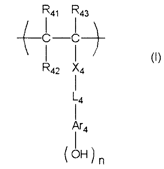
R41、R42及びR43は、各々独立に、水素原子、アルキル基、ハロゲン原子、シアノ基又はアルコキシカルボニル基を表す。但し、R42はAr4と結合して環を形成していてもよく、その場合のR42は単結合又はアルキレン基を表す。
X4は、単結合、-COO-、又は-CONR64-を表し、R64は、水素原子又はアルキル基を表す。
L4は、単結合又はアルキレン基を表す。
Ar4は、(n+1)価の芳香環基を表し、R42と結合して環を形成する場合には(n+2)価の芳香環基を表す。
nは、1~5の整数を表す。
(n+1)価の芳香環基は、更に置換基を有していてもよい。
X4としては、単結合、-COO-、-CONH-が好ましく、単結合、-COO-がより好ましい。
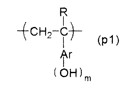

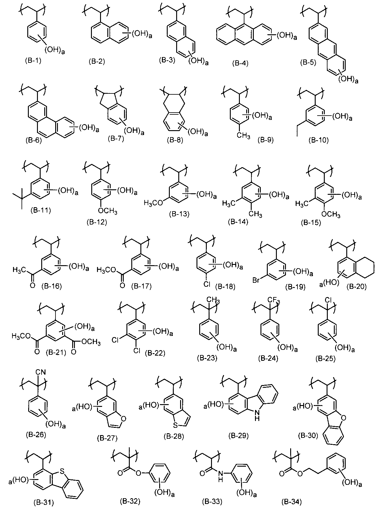
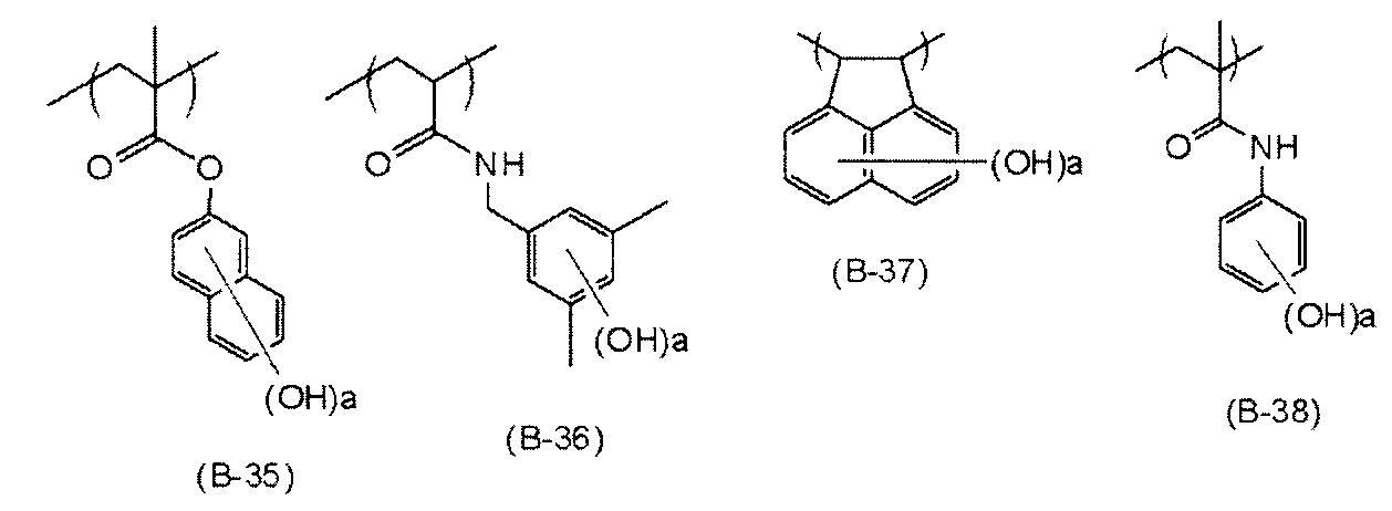
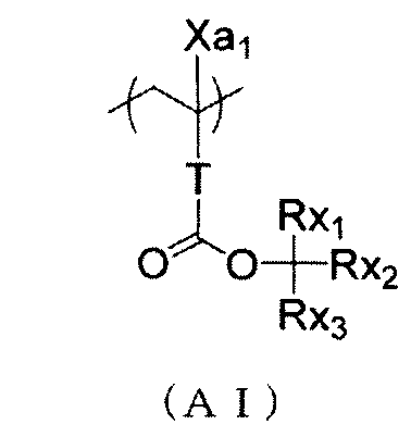
Xa1は、水素原子、置換基を有していてもよいアルキル基を表す。
Tは、単結合又は2価の連結基を表す。
Rx1~Rx3の2つが結合して、シクロアルキル基(単環若しくは多環)を形成してもよい。
Tは、単結合又は-COO-Rt-基が好ましい。Rtは、炭素数1~5のアルキレン基が好ましく、-CH2-基、-(CH2)2-基、-(CH2)3-基がより好ましい。

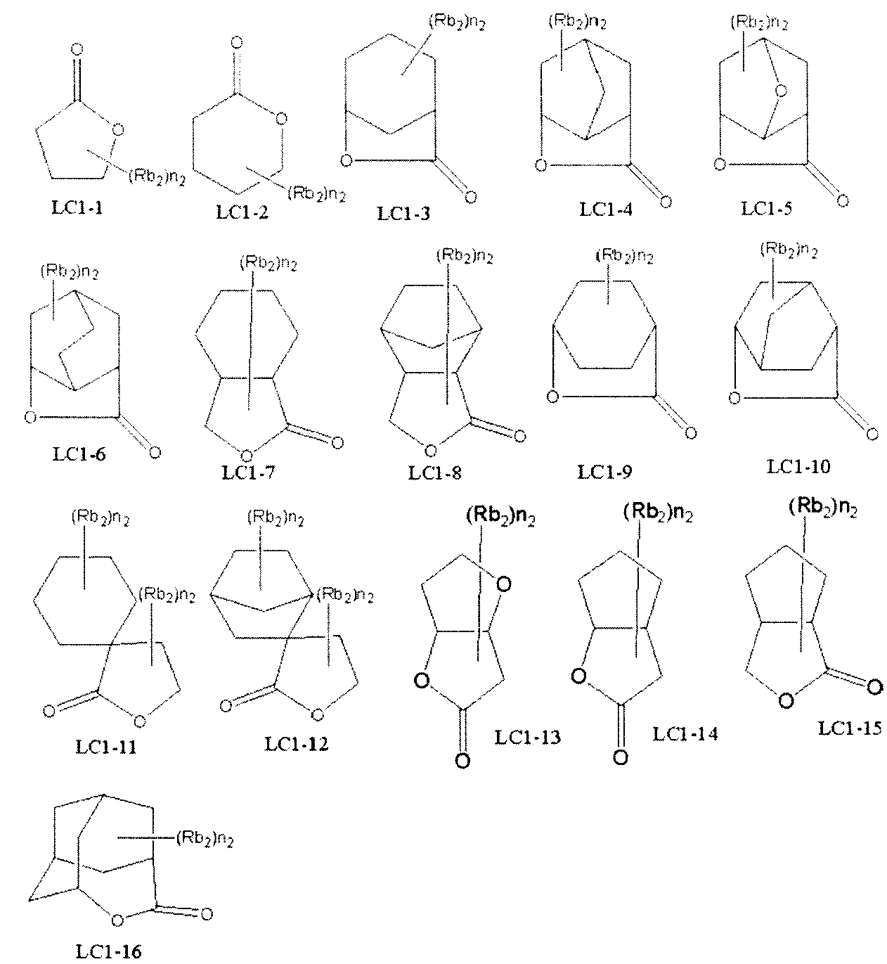

Rb0のアルキル基が有していてもよい好ましい置換基としては、水酸基、ハロゲン原子が挙げられる。
Rb0のハロゲン原子としては、フッ素原子、塩素原子、臭素原子、沃素原子を挙げることができる。Rb0は、水素原子又はメチル基が好ましい。
Abは、単結合、アルキレン基、単環又は多環の脂環炭化水素構造を有する2価の連結基、エーテル基、エステル基、カルボニル基、カルボキシル基、又はこれらを組み合わせた2価の基を表す。好ましくは、単結合、-Ab1-CO2-で表される連結基である。Ab1は、直鎖、分岐アルキレン基、単環又は多環のシクロアルキレン基であり、好ましくは、メチレン基、エチレン基、シクロヘキシレン基、アダマンチレン基、ノルボルニレン基である。
Vは、一般式(LC1-1)~(LC1-16)のうちのいずれかで示される基を表す。

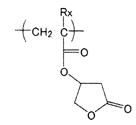
これにより基板密着性、現像液親和性が向上する。極性基で置換された脂環炭化水素構造の脂環炭化水素構造としてはアダマンチル基、ジアマンチル基、ノルボルナン基が好ましい。極性基としては水酸基、シアノ基が好ましい。
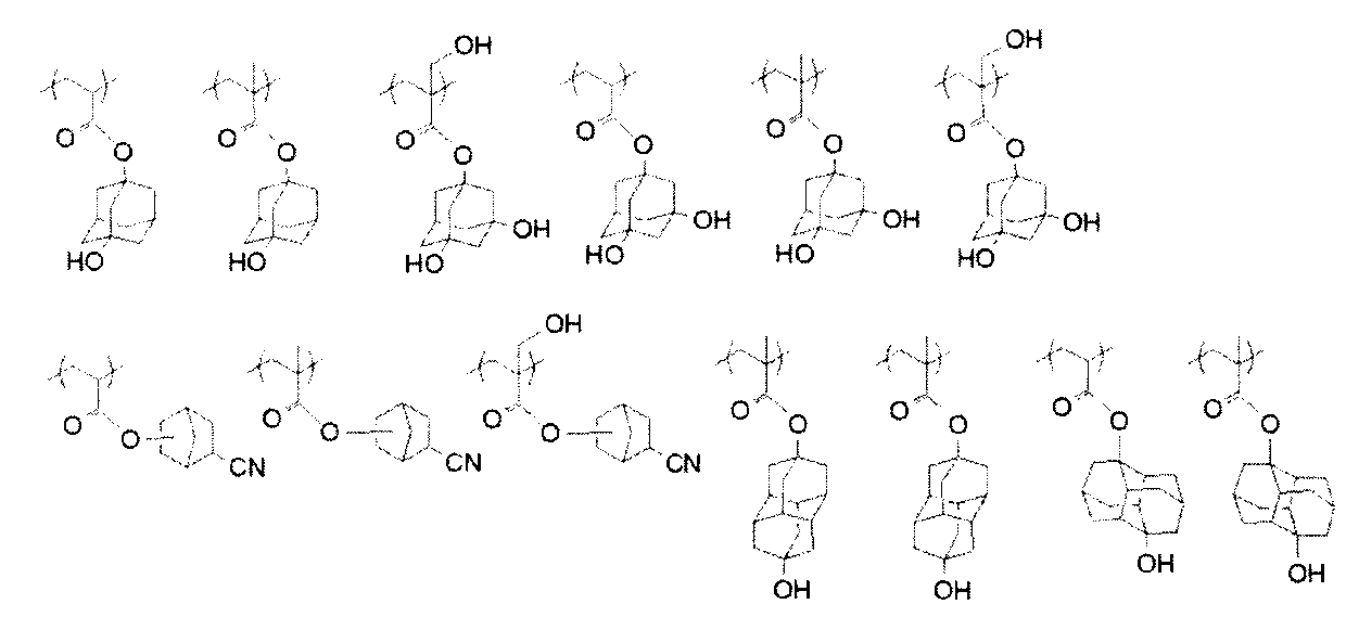
このような繰り返し単位としては、例えば、下記一般式(4)で表される繰り返し単位が挙げられる。
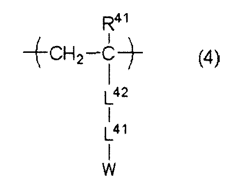
以下に、一般式(4)で表される繰り返し単位の具体例を示すが、本発明がこれに限定されるものではない。


R61、R62及びR63は、各々独立に、水素原子、アルキル基、シクロアルキル基、ハロゲン原子、シアノ基、又はアルコキシカルボニル基を表す。但し、R62はAr6と結合して環を形成していてもよく、その場合のR62は単結合又はアルキレン基を表す。
X6は、単結合、-COO-、又は-CONR64-を表す。R64は、水素原子又はアルキル基を表す。
L6は、単結合又はアルキレン基を表す。
Ar6は、(n+1)価の芳香環基を表し、R62と結合して環を形成する場合には(n+2)価の芳香環基を表す。
Y2は、n≧2の場合には各々独立に、水素原子又は酸の作用により脱離する基を表す。但し、Y2の少なくとも1つは、酸の作用により脱離する基を表す。
nは、1~4の整数を表す。
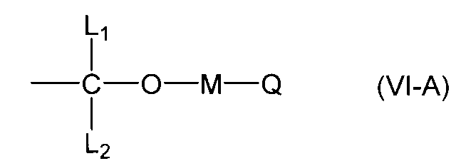
Mは、単結合又は2価の連結基を表す。
Qは、アルキル基、ヘテロ原子を含んでいてもよいシクロアルキル基、ヘテロ原子を含んでいてもよいアリール基、アミノ基、アンモニウム基、メルカプト基、シアノ基又はアルデヒド基を表す。
Q、M、L1の少なくとも2つが結合して環(好ましくは、5員若しくは6員環)を形成してもよい。

Ar3は、芳香環基を表す。
M3は、単結合又は2価の連結基を表す。
Q3は、アルキル基、シクロアルキル基、アリール基又はヘテロ環基を表す。
Q3、M3及びR3の少なくとも二つが結合して環を形成してもよい。
Ar3が表す芳香環基は、上記一般式(VI)におけるnが1である場合の、上記一般式(VI)におけるAr6と同様であり、より好ましくはフェニレン基、ナフチレン基であり、更に好ましくはフェニレン基である。


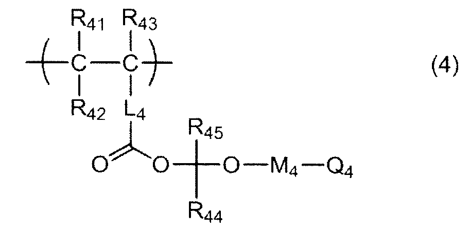
R41、R42及びR43は、各々独立に、水素原子、アルキル基、シクロアルキル基、ハロゲン原子、シアノ基又はアルコキシカルボニル基を表す。R42はL4と結合して環を形成していてもよく、その場合のR42はアルキレン基を表す。
R44及びR45は、水素原子、アルキル基、シクロアルキル基、アリール基、アラルキル基、アルコキシ基、アシル基又はヘテロ環基を表す。
M4は、単結合又は2価の連結基を表す。
Q4は、アルキル基、シクロアルキル基、アリール基又はヘテロ環基を表す。
Q4、M4及びR44の少なくとも二つが結合して環を形成してもよい。
R41、R42及びR43は、前述の一般式(V)中のR51、R52、R53と同義であり、また好ましい範囲も同様である。
L4は、前述の一般式(V)中のL5と同義であり、また好ましい範囲も同様である。
M4は、前述の一般式(3)中のM3と同義であり、また好ましい範囲も同様である。
Q4は、前述の一般式(3)中のQ3と同義であり、また好ましい範囲も同様である。
Q4、M4及びR44の少なくとも二つが結合して形成される環としては、Q3、M3及びR3の少なくとも二つが結合して形成される環があげられ、また好ましい範囲も同様である。
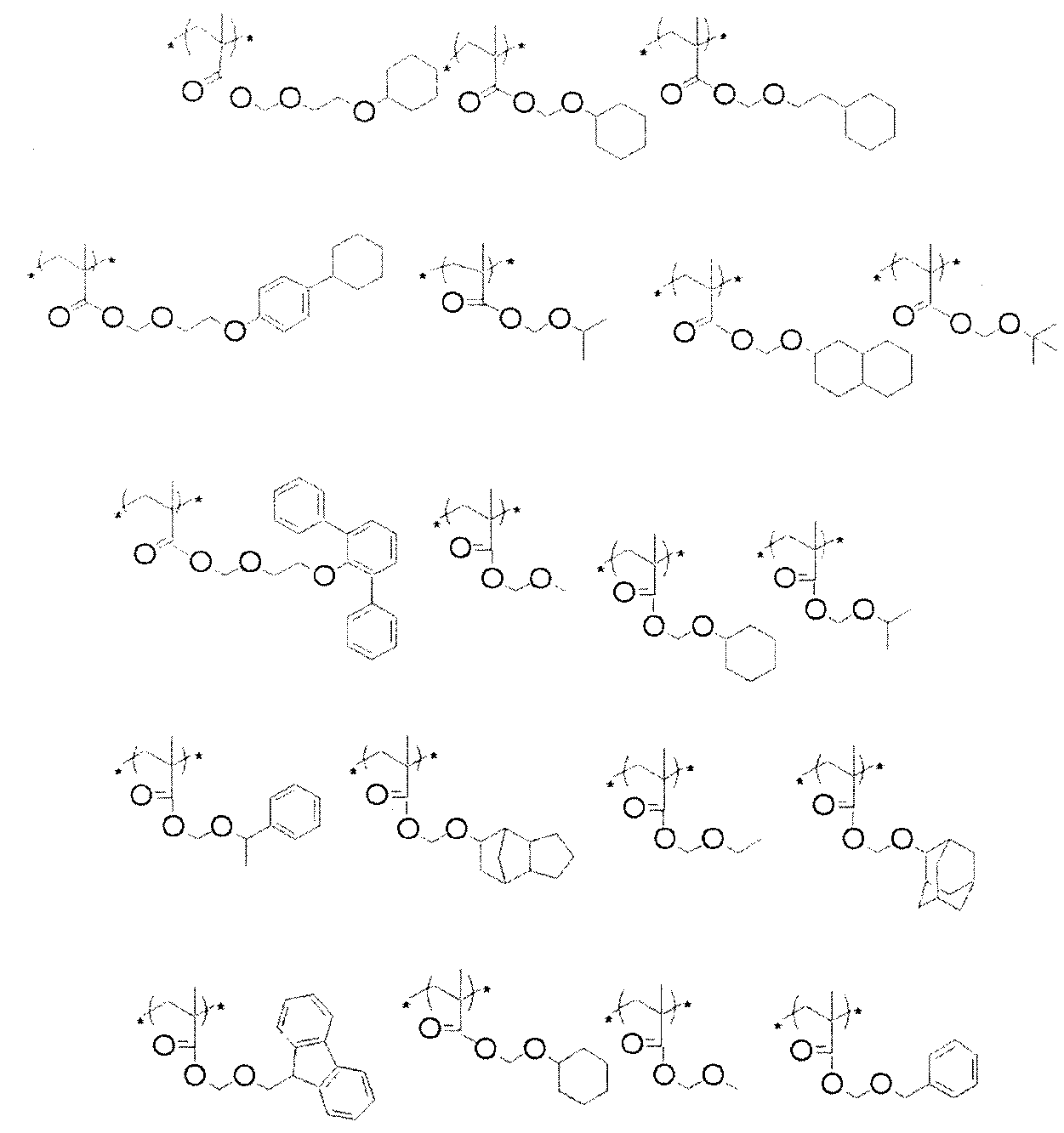

以下に、一般式(BZ)により表される繰り返し単位の具体例を示すが、これらに限定されるものではない。
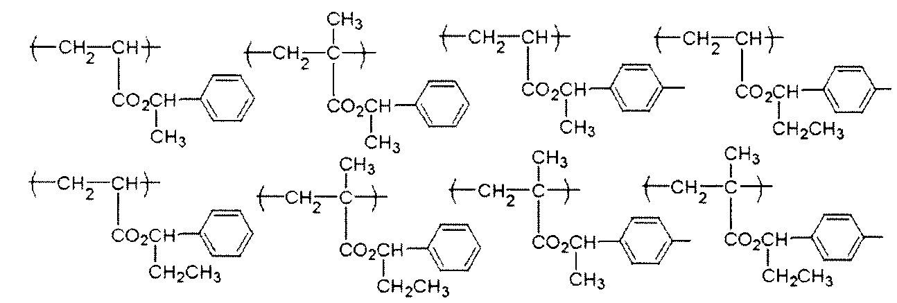
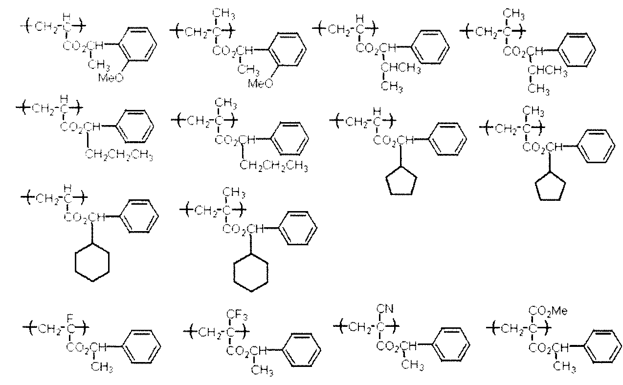
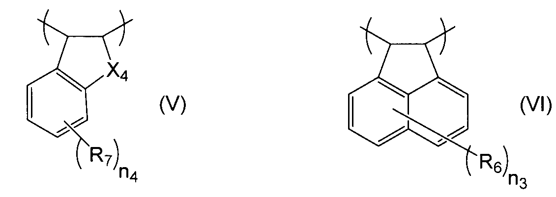
R6及びR7は、それぞれ独立に、水素原子、ヒドロキシ基、炭素数1~10の直鎖状、分岐状又は環状のアルキル基、アルコキシ基又はアシロキシ基、シアノ基、ニトロ基、アミノ基、ハロゲン原子、エステル基(-OCOR又は-COOR:Rは炭素数1~6のアルキル基又はフッ素化アルキル基)、又はカルボキシル基を表す。
n3は0~6の整数を表す。
n4は0~4の整数を表す。
X4はメチレン基、酸素原子又は硫黄原子である。

また、ランダム型シルセスキオキサン構造とは、骨格がランダムのシルセスキオキサン構造である。

感活性光線性又は感放射線性樹脂組成物は、活性光線又は放射線により酸を発生する化合物(以下、「光酸発生剤《PAG:Photo Acid Generator》」ともいう)を含有することが好ましい。

R201、R202及びR203は、各々独立に、有機基を表す。
R201、R202及びR203としての有機基の炭素数は、一般的に1~30、好ましくは1~20である。

Xfは、それぞれ独立に、フッ素原子、又は少なくとも1つのフッ素原子で置換されたアルキル基を表す。
R1、R2は、それぞれ独立に、水素原子、フッ素原子、又は、アルキル基を表し、複数存在する場合のR1、R2は、それぞれ同一でも異なっていてもよい。
Lは、二価の連結基を表し、複数存在する場合のLは同一でも異なっていてもよい。
Aは、環状の有機基を表す。
xは1~20の整数を表し、yは0~10の整数を表し、zは0~10の整数を表す。
Xfのフッ素原子で置換されたアルキル基におけるアルキル基としては、好ましくは炭素数1~10であり、より好ましくは炭素数1~4である。また、Xfのフッ素原子で置換されたアルキル基は、パーフルオロアルキル基であることが好ましい。
特に、双方のXfがフッ素原子であることが好ましい。
xは1~10が好ましく、1~5がより好ましい。
yは0~4が好ましく、0がより好ましい。
zは0~5が好ましく、0~3がより好ましい。
一般式(ZII)、(ZIII)中、R204~R207は、各々独立に、アリール基、アルキル基又はシクロアルキル基を表す。



上述した各成分を溶解させて感活性光線性又は感放射線性樹脂組成物を調製する際には、溶剤を使用できる。使用できる溶剤としては、例えば、アルキレングリコールモノアルキルエーテルカルボキシレート、アルキレングリコールモノアルキルエーテル、乳酸アルキルエステル、アルコキシプロピオン酸アルキル、炭素数4~10の環状ラクトン、炭素数4~10の、環を含有してもよいモノケトン化合物、アルキレンカーボネート、アルコキシ酢酸アルキル、ピルビン酸アルキル等の有機溶剤を挙げることができる。
本発明に於いては、上記溶剤を単独で使用してもよいし、2種類以上を併用してもよい。
溶剤としては、例えば特開2014-219664号公報の段落0013~0029に記載の溶媒も使用できる。
感活性光線性又は感放射線性樹脂組成物は、露光から加熱までの経時による性能変化を低減するために、塩基性化合物(D)を含有することが好ましい。

R202は、互いに結合して環を形成してもよい。
R203、R204、R205及びR206 は、同一でも異なってもよく、炭素数1~20個のアルキル基を表す。
これら一般式(A)及び(E)中のアルキル基は、無置換であることがより好ましい。
アミン等を挙げることができる。水酸基及び/又はエーテル結合を有するアニリン誘導体としては、N,N-ビス(ヒドロキシエチル)アニリン等を挙げることができる。
(プロトンアクセプター性官能基を有し、かつ、活性光線又は放射線の照射により分解してプロトンアクセプター性が低下、消失、又はプロトンアクセプター性から酸性に変化した化合物を発生する化合物(PA))
本発明に係る組成物は、塩基性化合物として、プロトンアクセプター性官能基を有し、かつ、活性光線又は放射線の照射により分解してプロトンアクセプター性が低下、消失、又はプロトンアクセプター性から酸性に変化した化合物を発生する化合物〔以下、化合物(PA)ともいう〕を更に含んでいてもよい。

感活性光線性又は感放射線性樹脂組成物は、上記樹脂(A)とは別に疎水性樹脂(A’)を有していてもよい。
疎水性樹脂を添加することの効果として、水に対するレジスト膜表面の静的/動的な接触角の制御、アウトガスの抑制などを挙げることができる。
疎水性樹脂がフッ素原子を含んでいる場合、フッ素原子を有する部分構造として、フッ素原子を有するアルキル基、フッ素原子を有するシクロアルキル基、又は、フッ素原子を有するアリール基を有する樹脂であることが好ましい。
ここで、疎水性樹脂中の側鎖部分が有するCH3部分構造には、エチル基、プロピル基等が有するCH3部分構造を包含するものである。
なお、疎水性樹脂としてはこの他にも特開2011-248019号公報、特開2010-175859号公報、特開2012-032544号公報記載のものも好ましく用いることができる。
感活性光線性又は感放射線性樹脂組成物は、界面活性剤(E)を更に含んでいてもよい。界面活性剤を含有することにより、波長が250nm以下、特には220nm以下の露光光源を使用した場合に、良好な感度及び解像度で、密着性及び現像欠陥のより少ないパターンを形成することが可能となる。
これら界面活性剤は、1種類を単独で用いてもよく、2種類以上を組み合わせて用いてもよい。
感活性光線性又は感放射線性樹脂組成物は、溶解阻止化合物、染料、可塑剤、光増感剤、光吸収剤、及び/又は現像液に対する溶解性を促進させる化合物(例えば、分子量1000以下のフェノール化合物、又はカルボキシ基を含んだ脂環族若しくは脂肪族化合物)を更に含んでいてもよい。
本発明のパターン形成方法においては、レジスト膜の上層に上層膜(トップコート膜)を形成してもよい。
3-61648号公報に記載されたような塩基性化合物を含有する上層膜をレジスト膜上に形成することが好ましい。上層膜が含み得る塩基性化合物の具体的な例は、塩基性化合物(E)が挙げられる。
上層膜形成用組成物は樹脂を含有することが好ましい。上層膜形成用組成物が含有することができる樹脂としては、特に限定されないが、感活性光線性又は感放射線性組成物に含まれ得る疎水性樹脂(例えば、上述した疎水性樹脂(A’))と同様のものを使用することができる。
樹脂の重量平均分子量は好ましくは3000~100000であり、更に好ましくは3000~30000であり、最も好ましくは5000~20000である。上層膜形成用組成物中の樹脂の配合量は、全固形分中、50~99.9質量%が好ましく、60~99.0質量%がより好ましく、70~99.7質量%が更に好ましく、80~99.5質量%が更により好ましい。
上層膜形成用組成物は、各成分を溶剤に溶解し、フィルターろ過することが好ましい。フィルターとしては、ポアサイズ0.1μm以下、より好ましくは0.05μm以下、更に好ましくは0.03μm以下のポリテトラフロロエチレン製、ポリエチレン製、ナイロン製のものが好ましい。なお、フィルターは、複数種類を直列又は並列に接続して用いてもよい。また、組成物を複数回ろ過してもよく、複数回ろ過する工程が循環ろ過工程であっても良い。さらに、フィルターろ過の前後で、組成物に対して脱気処理などを行ってもよい。上層膜形成用組成物は、金属等の不純物を含まないことが好ましい。これら材料に含まれる金属成分の含有量としては、10ppm以下が好ましく、5ppm以下がより好ましく、1ppm以下が更に好ましく、実質的に含まないこと(測定装置の検出限界以下であること)が特に好ましい。
上層膜の屈折率は、解像性の観点から、感活性光線性又は感放射線性膜の屈折率に近いことが好ましい。
上層膜は液浸液に不溶であることが好ましく、水に不溶であることがより好ましい。
上層膜の後退接触角は、液浸液追随性の観点から、上層膜に対する液浸液の後退接触角(23℃)が50~100度であることが好ましく、80~100度であることがより好ましい。
以下に、各種処理液の合成例を説明する。但し、下記合成例に限定されるものではなく、公知の方法を用いて合成することができる。
<原料等の精製>
以下に示す各実施例で使用される各原料、各触媒は、純度99質量%以上の高純度グレードを用い、さらに事前に蒸留、イオン交換、ろ過等によって精製したものである。また、以下に示すエステル化反応に使用する触媒は硫酸である。この触媒として使用する硫酸は、純度98質量%以上のものであるが、希硫酸を供給して、所定濃度範囲に脱水しながら使用することもできる。
酢酸ブチル含有処理液(処理液1A)の合成
(工程1)
酢酸及びn-ブタノールを、触媒としての硫酸の存在下、連続式の槽型反応器で予備反応させた。次いで、得られた反応液1aを、連続式の反応蒸留塔において、酢酸ブチル/n-ブタノール/水の共沸混合物として副生する水を蒸留塔の塔頂から系外に除去しながら反応させることにより、酢酸ブチルを含む粗液(以下、「酢酸ブチル粗液」という。)1bを得た。
工程1で得られた酢酸ブチル粗液1bについて、硫酸分をアルカリ中和した。次いで、水で洗浄した後、水分の除去を行うことにより、酢酸ブチル粗液1cを取り出した。
工程2で得られた酢酸ブチル粗液1cを中和水洗し、デカンターにより大部分の水及び硫酸を分離した。次いで、酢酸ブチル、n-ブタノール、水、硫酸及び微量の副生物を含む酢酸ブチル粗液1dを、不純物のn-ブタノール及び水等の低沸物を除去する目的で蒸留塔に供給した。その後、蒸留を複数回繰り返し目的性生物である、酢酸ブチル含有処理液(処理液1A)を得た。
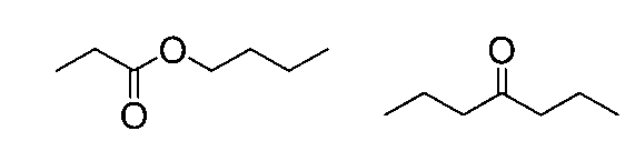
1-ヘキサノール含有処理液(処理液2A)の合成
(原料等)
1-ヘキサノールは以下の2段の反応式で合成される。
Al(C6H13)3+3/2O2+3H2O→3HOC6H13+Al(OH)3
(工程1)
公知の方法により、上掲の1段目の反応によってポリマー化したAl(C6H15)3を得た。次いで、このAl(C6H15)3を触媒として、酸素及び水の共存下において、公知の方法に従い、1-ヘキサノールの合成を行った。そこでは、40℃で10時間の加熱処理を行い、1-ヘキサノールを含む粗液(以下、「1-ヘキサノール粗液」という。)2aを得た。Alは、水酸化アルミニウムとして除去した。
工程1で得られた1-ヘキサノール粗液2aは、Al(OH)3の沈殿物を含む為、ろ過によってAl(OH)3の除去を行い、1-ヘキサノール粗液2bを得た。
工程2で得られた1-ヘキサノール粗液2bを、副生成物の置換異性体、高級アルコール等を除去する目的で蒸留塔に供給した。その後、蒸留を複数回繰り返し目的性生物である1-ヘキサノール含有処理液(処理液2A)を得た。

4―メチル-2-ペンタノール含有処理液(処理液3A)の合成
(工程1)
シス-4-メチル-2-ペンテンを、触媒としてのIpc2BH(Diisopinocampheylborane)の存在下において、公知の方法に従い、4-メチル-2-ペンタノールの合成を行った。そこでは、80℃で4時間の加熱処理を行い、シス-4-メチル-2-ペンテンとIpc2BHがホウ素を経由して結合した中間体を経て、4-メチル-2-ペンタノールを含む粗液(以下、「4-メチル-2-ペンタノール粗液」という。)3aを得た。
工程1で得られた4-メチル-2-ペンタノール粗液3aは、未反応のcis-4-methyl-2-pentene、不純物としての置換異性体を含んでいる。
この4-メチル-2-ペンタノール粗液3aを、精製する目的で蒸留塔に供給した。蒸留を複数回繰り返し、目的性生物である4-メチル-2-ペンタノール含有処理液(処理液3A)を得た。
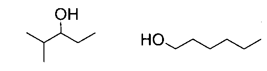
PGMEA(プロピレングリコールモノメチルエーテルアセタート)含有処理液(処理液4A)の合成
(工程1)
プロピレンオキシド、メタノール、酢酸を、触媒として硫酸の存在下、公知の方法に従い、PGMEAの合成(2段階合成)を行った。そこでは、80℃で8時間の加熱処理を行い、PGMEAを含む粗液(以下、「PGMEA粗液」という。)4aを得た。
工程1で得られたPGMEA粗液4aは、未反応のプロピレンオキシド、メタノール、酢酸、不純物としての置換異性体を含んでいる。
このPGMEA粗液4aを精製する目的で蒸留塔に供給した。蒸留を複数回繰り返し、目的性生物であるPEGMEA含有処理液(処理液4A)を得た。
得られたPGMEA含有処理液(処理液4A)中に含有される化合物(B)は、下記化合物であった。これら化合物は、いずれも処理液中の含有率が要件(b)を満たしていた(表2を参照)。

IPA(イソプロパノール)含有処理液(処理液5A)の合成
(工程1)
アセトン及び水素を用い、触媒として酸化銅-酸化亜鉛-酸化アルミニウムの存在下、公知の方法に従い、アセトンの還元反応を行った。そこでは、100℃で4時間の加熱処理を行い、IPAを含む粗液(以下、「IPA粗液」という。)5aを得た。
IPA粗液5aは、未反応のアセトン、不純物としての置換異性体及び触媒を含んでいる。このIPA粗液5aを精製する目的で蒸留塔に供給した。蒸留を複数回繰り返し、目的性生物であるIPA含有処理液(処理液5A)を得た。

乳酸エチル(Ethyl lactate;EL)含有処理液(処理液6A)の合成
(工程1)
乳酸とエタノールを用い、特開昭62-26249号公報に記載のエステル化法で、乳酸エチルを含有する粗液(以下、「乳酸粗液」という。)6aを得た。
工程1で得られた乳酸エチル粗液6aは、副生の水またはアルコ-ルと未反応の原料エタノールを含んでいる。
得られた乳酸エチル粗液6aを精製する目的で蒸留塔に供給した。その後、蒸留を複数回繰り返し、乳酸エチル含有処理液(処理液6A)を得た。
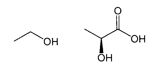
シクロヘキサノン含有処理液(処理液7A)の合成
(工程1)
特開2007-63209号公報に記載の方法により、ベンゼンと塩素より、モノクロルベンゼンと塩化水素を得た。次いで、モノクロルベンゼンと水より、フェノールと塩化水素を得た。次いで、フェノールと水素より、シクロヘキサノンを含む粗液(以下、「シクロヘキサノン粗液」という。)7aを得た。
工程1において、反応塔から得られたシクロヘキサノン粗液7aは、未反応のベンゼン、モノクロロベンゼン、フェノール等を含んでいる。
得られたシクロヘキサノン粗液7aを精製する目的で蒸留塔に供給した。その後、蒸留を複数回繰り返し、シクロヘキサノン含有処理液(処理液7A)を得た。

PGME(プロピレングリコールモノメチルエーテル)含有処理液(処理液8A)の合成
(工程1)
特開2008-208035号公報に記載の方法により、メタノールとプロピレンオキシドとを90~110℃で反応させることにより、PGMEを含む粗液(以下、「PGME粗液」という。)8aを得た。
工程1において、反応塔から得られたPGME粗液8aは、未反応のメタノール、プロピレンオキシド、触媒の三級アミン等を含んでいる。
得られたPGME粗液8aを精製する目的で蒸留塔に供給した。その後、蒸留を複数回繰り返し、PGME含有処理液(処理液8A)を得た。
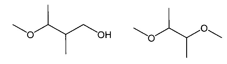
MMP(3-メトキシプロピオン酸メチル)含有処理液(処理液8A)の合成
(工程1)
特開2007-63209号公報に記載の方法により、メタノールと塩基性触媒のカリウムt-ブトキシド(KOt-Bu)とアクリル酸メチル74.0g(0.86モル)を秤量し、滴下ロートから徐々に約1時間かけて滴下した。この際、アクリル酸メチルを少量滴下すると発熱するので、氷水で冷却しながら40℃の反応温度に制御した。滴下終了後、40℃下で1時間加熱撹拌し、トータルの反応時間を2時間とした。
その後、りん酸を添加し、pH試験紙で中性であることを確認後、室温で30分間撹拌した。中和後は、吸引ろ過を行い、触媒の中和塩の固形物をろ別し、MMPを含む粗液(以下、「MMP粗液」という。)9aを得た。
工程1において、反応塔から得られたMMP粗液9aは、未反応のメタノール、アクリル酸メチル等を含んでいる。
得られたMMP粗液9aを精製する目的で蒸留塔に供給した。その後、蒸留を複数回繰り返し、MMP含有処理液(処理液9A)を得た。

1)標準物質の準備
清浄なガラス容器内へ超純水を計量投入し、メディアン径50nmの測定対象金属粒子を10000個/mlの濃度となるように添加した後、超音波洗浄機で30分間処理した分散液を輸送効率測定用の標準物質として用いた。
メーカー:PerkinElmer
型式:NexION350S
3)SNP-ICP-MSの測定条件
SNP-ICP-MSはPFA製同軸型ネブライザ、石英製サイクロン型スプレーチャンバ、石英製内径1mmトーチインジェクタを用い、測定対象液を約0.2mL/minで吸引した。酸素添加量は0.1L/min、プラズマ出力1600W、アンモニアガスによるセルパージを行った。時間分解能は50usにて解析を行った。
・金属粒子の含有率:ナノ粒子分析“SP-ICP-MS”専用Syngistix ナノアプリケーションモジュール
・金属原子の含有率:Syngistix for ICP-MS ソフトウエア
結果を後掲の表1に示す。
各実施例及び各比較例で使用した各成分については、GC/MS(Gas Chromatograph/Mass Spectrometer)、LC/MS(Liquid Chromatograph/Mass Spectrometer)、NMR(Nuclear magnetic resonance)及びIC(Ion Chromatography)によって測定した。有機物測定はGC/MS、LC/MS及びNMRで行い、無機物の分析に関してはICにて行った。
[GC/MS](ガスクロマトグラフ質量分析計)
(測定条件)
装置:島津製作所社製 「GCMS-2020」
[LC/MS](液体クロマトグラフ質量分析計)
(測定条件)
装置:サーモフィーシャーズ社製
「UPLC-H-Class, Xevo G2-XS QTof」
[NMR](核磁気共鳴)
(測定条件)
装置:日本電子製 AL400型
測定核:1H
溶媒:CDCl3
[IC](イオンクロマトグラフィ)
(測定条件)
装置:島津製作所社製 「HIC-SP」。
尚、表1の無機物(C)における「S」、「Al」、「B」、「N」及び「K」の欄は、各々、Sを含有する無機物、Alを含有する無機物、Bを含有する無機物、Nを含有する無機物、及び、Kを含有する無機物の含有率を表す。
シリコンウエハー上に有機反射防止膜ARC29A(日産化学社製)を塗布し、205℃で、60秒間ベークを行い、膜厚78nmの反射防止膜を形成した。その後に市販品FAiRS-9101A12(富士フイルムエレクトロニクスマテリアルズ(株)製ArFレジスト組成物)をスピンコーターを用いて塗布し、100℃で、60秒間ベークを行った。得られたウエハーをArFエキシマレーザースキャナー(NA0.75)を用い、25[mJ/cm2]でウエハ全面露光を行った。その後120℃で、60秒間加熱した。このウエハを2cm×2cmにカットして表1に記載の各処理液に、23℃において10分間浸漬した。浸漬前後の膜厚を光学式膜厚測定器エリプソメトリーにて測定し溶解速度(ER)を算出した。
結果を表1に示す。
ウェハ表面検査装置(SP-5;KLA Tencor製)により、直径300mmのシリコン基板表面に存在する直径32nm以上のパーティクル(以下、これを「欠陥」という。)数を計測した。次いで、このシリコン基板をスピン吐出装置にセットし、回転させながら、同シリコン基板の表面へ、表1に記載の各種処理液を1.5L/minの流速で吐出した。その後、リンス処理を行い、乾燥した。得られた試料について、再び上記装置(SP-5)を用いてシリコン基板表面に存在する欠陥数の計測を行い、初期値との差分を欠陥数とした。得られた欠陥数を下記基準に基づき評価した結果を表1に示す。下記基準において、評価Dは、半導体製造用処理液として要求される欠陥の抑制性能を達成している。
B:欠陥数が50個を超え、100個以下だった。
C:欠陥数が100個を超え、500個以下だった。
D:欠陥数が500個を超え、1000個以下だった。
E:欠陥数が1000個を超えた。
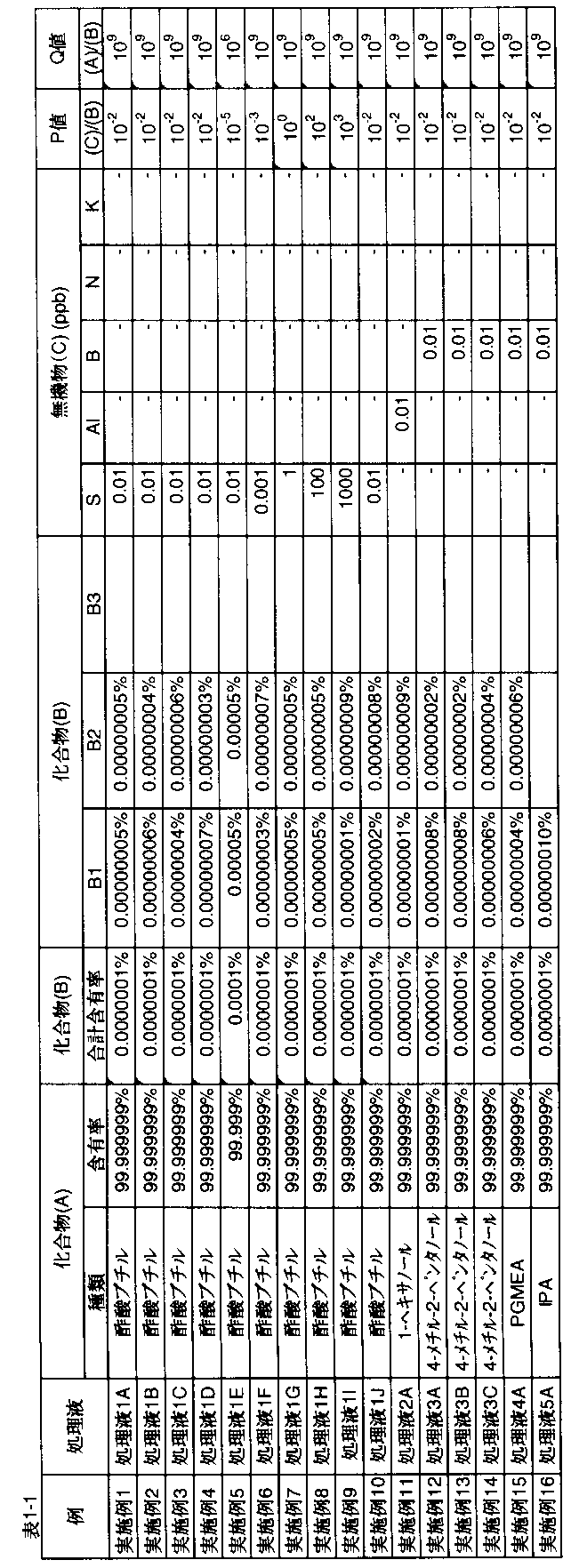


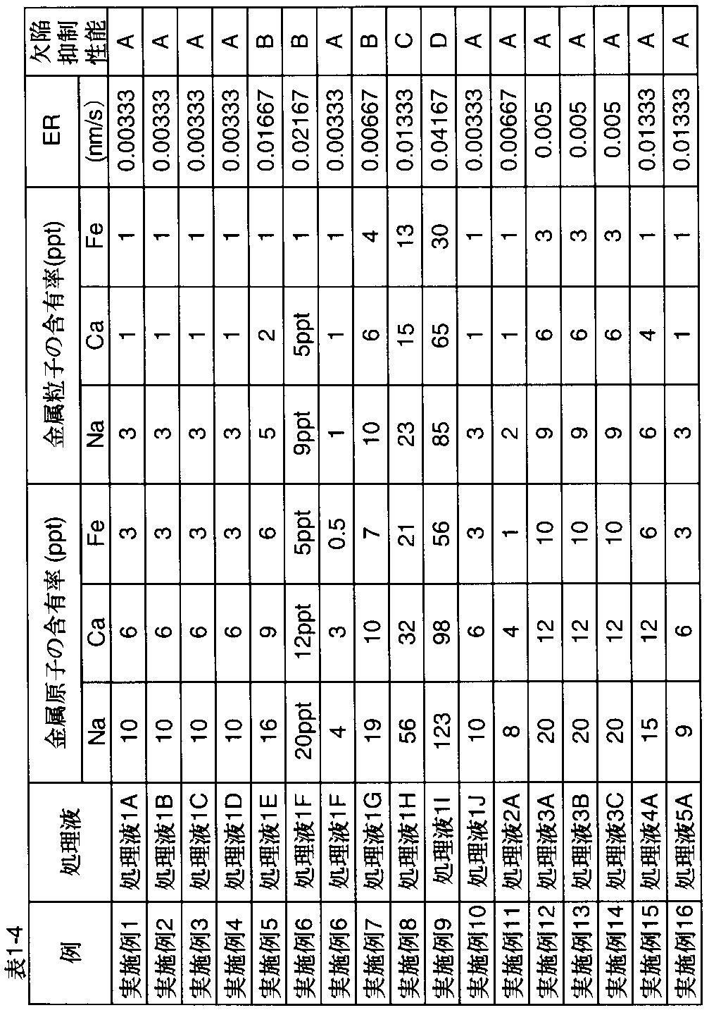
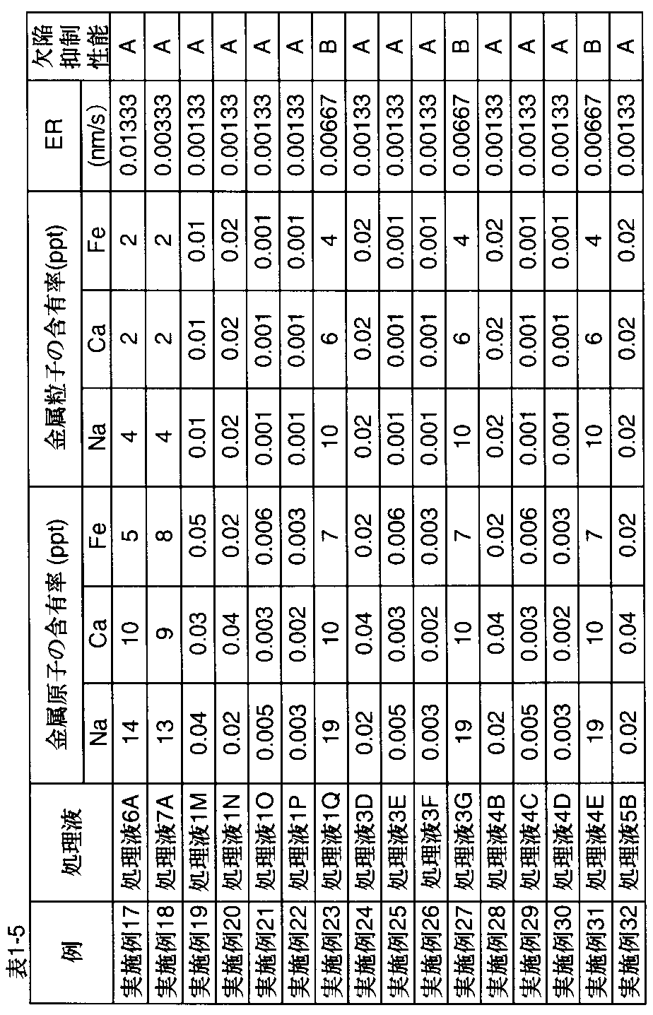
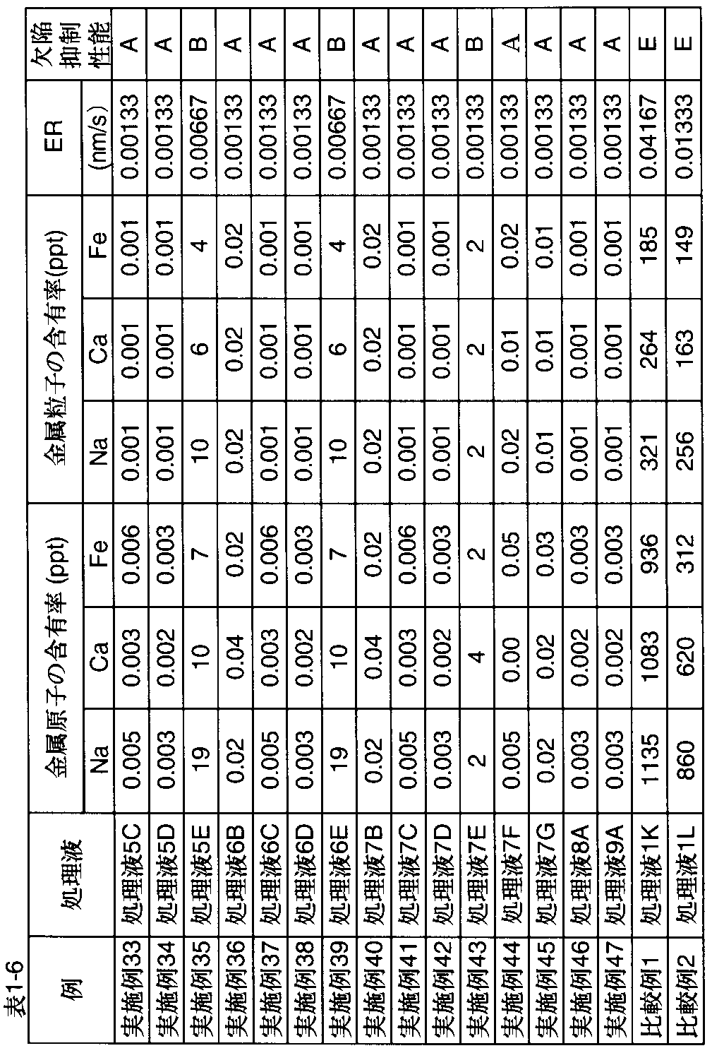
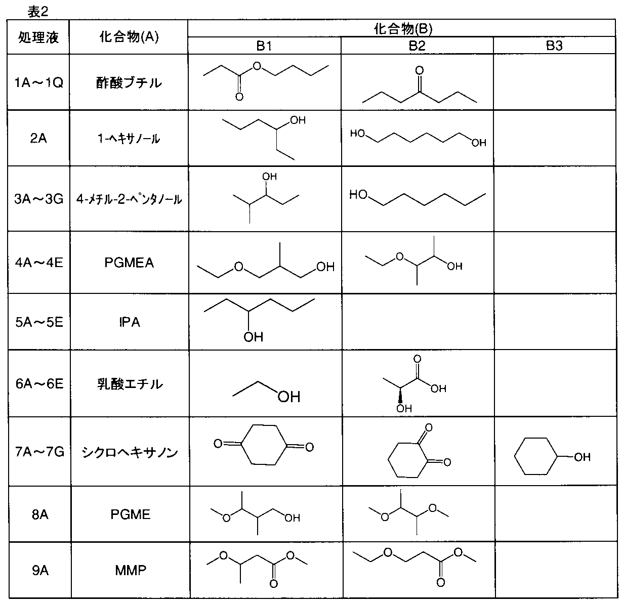
上掲で得られたシクロヘキサノン(CyHx)の粗液7aを、以下に示す方法で精製することにより、表1に示す処理液7B~7D及び7F~7Gを得た。
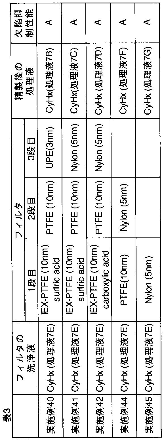
[実施例101~112、比較例101、102]
シリコンウエハー上に有機反射防止膜ARC29A(日産化学社製)を塗布し、205℃で、60秒間ベークを行い、膜厚78nmの反射防止膜を形成した。その上に市販品FAiRS-9101A12(富士フイルムエレクトロニクスマテリアルズ(株)製ArFレジスト組成物)をスピンコーターを用いて塗布し、100℃で、60秒間ベークを行い、膜厚150nmのレジスト膜を形成した。得られたウエハーをArFエキシマレーザースキャナー(NA0.75)を用い、25[mJ/cm2]でパターン露光を行った。その後120℃で、60秒間加熱した後、表4に記載の各処理液で30秒間現像(ネガ型現像)し、L/Sパターンを得た。
シリコンウエハー上に有機反射防止膜ARC29A(日産化学社製)を塗布し、205℃で、60秒間ベークを行い、膜厚78nmの反射防止膜を形成した。その後、塗布性を改良する為に、表3に記載の処理液を予めかけるプリウェット工程を行った。その後に市販品FAiRS-9101A12(富士フイルムエレクトロニクスマテリアルズ(株)製ArFレジスト組成物)をスピンコーターを用いて塗布し、100℃で、60秒間ベークを行い、膜厚150nmのレジスト膜を形成した。得られたウエハーをArFエキシマレーザースキャナー(NA0.75)を用い、25[mJ/cm2]でパターン露光を行った。その後120℃で、60秒間加熱した後、表4に記載の処理液で30秒間現像(ネガ型現像)し、得られたパターンを表1に記載の処理液でリンス洗浄し、L/Sパターンを得た。
パターン形成後、ラインパターン上面およびスペース部分を測長走査型電子顕微鏡(日立社製S9380II)を使用して観察した。形成したパターン寸法の値が小さいほど良好な性能であることを示す。下記基準において、評価Dは、レジストパターンとして要求されるリソ性能を達成している。
評価結果を表4に示す。
B L/S=80nm以上120nm未満
C L/S=120nm以上150nm未満
D L/S=150nm以上200nm未満
E L/S=200nm以上

ジメチルスルホキシド(和光純薬)を準備し、特開2007―254168号公報に記載されている方法により精製を行い、Na、Ca、Feの含有率が、各々10質量ppb未満であることを確認した後、処理液の調整に用いた。
実施例1の処理液1Aの液を90.5質量部と、上記で得られたジメチルスルホキシドを9.5質量部とを混合し、処理液X-1を準備した。
処理液X-1は、処理液1Aと上記ジメチルスルホキシド以外に、要件(b)を満たす2種以上の化合物(B)と、無機物(C)とを含有し、化合物(B)の含有率の合計が、10-10~0.1質量%であり、式Iで表される化合物(B)と無機物(C)の比率Pが103~10-6であった。この処理液X-1を用いて実施例1及び実施例101と同様の評価を行ったところ、実施例1と同様の欠陥抑制性能、及び、実施例101と同様のリソ性能が得られた。
実施例1の処理液1Aの液を95質量部と、上記で得られたジメチルスルホキシドを5質量部とを混合し、処理液X-2を準備した。
実施例1の処理液1Aの液を85質量部と、上記で得られたジメチルスルホキシドを15質量部とを混合し、処理液X-3を準備した。この処理液X-3を用いて実施例1及び実施例101と同様の評価を行ったところ、実施例1と同様の結果が得られたが、リンス後に処理液残りがあり乾燥に時間がかかった。
後掲の表5に示す第一処理液と第二処理液を、同表に示す割合で混合し、処理液101~106を調製した。また、表5に示す処理液107は、上掲で調製した処理液9Aである。これら処理液101~107に対し、上述した方法と同じ方法で欠陥抑制性能を評価した。また、これらの処理液をプリウェット液として用いたときの省レジスト性を評価した。また、アッシング後又はp-CMP後にこれらの処理液をリンス液として用いた時の性能を評価した。結果を表5に示す。
各処理液をプリウェット溶液として用いた場合の省レジスト性を以下の方法により評価した。なお、本明細書において、優れた省レジスト性を有する、とは、優れた均一性と、優れた膜厚制御性とを有する状態を意味し、これによりリソ性能の悪化や欠陥の発生を抑制できることがわかる。
使用したレジスト組成物1は、下記の通りである。
下記に示す酸分解性樹脂、光酸発生剤、クエンチャー、疎水性樹脂及び溶剤を混合し、固形分濃度3.5質量%のレジスト組成物1を調製した。
下記に示す酸分解性樹脂:100質量部


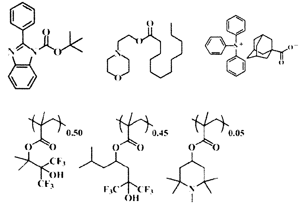
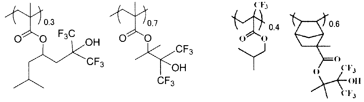
PGMEA(和光社製):3質量部
CyHx(シクロヘキサノン)(和光社製):600質量部
GBL(γ-ブチロラクトン)(和光社製):100質量部。
レジスト組成物1に対し、上記溶剤1(PGMEA:CyHx:GBL=3質量部:600質量部:100質量部)に替え、下記溶剤2を使用したこと以外はレジスト組成物1と同じ条件でレジスト組成物2を調製した。
処理液4A(PGMEA):3質量部
処理液7D(CyHx):600質量部
GBL(γ-ブチロラクトン)(和光社製):100質量部。
まず、対照として、反射防止膜を備える直径約30cm(12インチ)のシリコンウェハ上に上記レジスト組成物1(又はレジスト組成物2)を直接塗布した。なお、塗布には、スピンコータ(商品名「LITHIUS」、東京エレクトロン社製)を用いた。得られたレジスト膜は90℃でベークした。ベーク後のレジスト膜について、大日本スクリーン社製膜厚測定装置Lambda Aceを用いて59ポイントmap測定して、塗布斑が発生していないことを確認した。なお、塗布斑とは、測定対象のレジスト膜から円状に59点の測定点を抽出し、各測定点におけるレジスト膜の厚みの測定結果を、測定点ごとに二次元的に配置して観察した場合に、レジスト膜の厚みにムラがない状態を意図する。
結果は以下の基準により評価し結果を表5に示した。
A:レジスト組成物の使用量を、対照の50質量%に減量しても塗布斑は発生しなかったが、対照の30質量%に減量すると、塗布斑が発生した。
B:レジスト組成物の使用量を対照の30質量%に減量した場合、及び、50質量%に減量した場合のいずれにおいても塗布斑が発生した。
反射防止膜を備える直径約30cm(12インチ)のシリコンウェハ上に、各処理液を滴下した。その後、得られるレジスト膜の厚みが8.5nmとなるよう、上記レジスト組成物1(又はレジスト組成物2)を直接塗布した。なお、塗布には、スピンコータ(商品名「LITHIUS」、東京エレクトロン社製)を用いた。得られたレジスト膜は90℃でベークした。ベーク後のレジスト膜について、大日本スクリーン社製膜厚測定装置Lambda Aceを用いて59ポイントmap測定し、レジスト膜の厚みの標準偏差(以下「σ」ともいう。)を求めた。次に、標準偏差から3σを求めた。
結果は以下の基準により評価し、表5に示した。
B:3σが0.15nm以上、0.2nm未満だった。
C:3σが0.2nm以上だった。
シリコンウェハ上にレジスト組成物1(又はレジスト組成物2)を塗布し、露光(50mJ)、加熱(220℃)によって乾固したレジスト膜(膜厚0.5μm)を備える12インチウェハを準備した。次に、プラズマガスを用いて、上記レジスト膜を下記条件によりアッシング除去した。次いで、表5に示す各処理液(処理液101~107)を用いて洗浄し、アッシング除去後の残渣(アッシング残渣)を除去した。その後、SP-2(KLA TENCOL社製)を用いて、洗浄後のウェハの欠陥数をカウントすることにより、アッシング残渣に対する各処理液のリンス性能を評価した。
[アッシング除去の条件]
ウェーハ温度:250℃
O2ガス流量:1,000sccm
圧力:70Pa,
マイクロ波出力:1kW
-評価基準-
AA :欠陥数が50個以下だった。
A :欠陥数が50個を超え、80個以下だった。
B :欠陥数が80個を超え、100個以下だった。
C :欠陥数が100個を超え、150個以下だった。
D :欠陥数が150個を超えた。
CSL9044C(FFPS社製スラリー)で直径12インチのセマテック845(銅配線、バリアメタルTaN、酸化膜TEOS;セマテック社製)の表面を研磨して平坦化した。その後、BSL8178C(FFPS社製スラリー)で仕上げ研磨を行った。
次に、Clean100(和光純薬品)にて洗浄後、各処理液をリンス液として使用した。その後、パターン欠陥装置(AMAT社製 ComPLUS)を用いて、上記セマティック854のパターン上の欠陥数を測定した。結果は以下の基準により評価した。
AA :欠陥数が50個以下だった。
A :欠陥数が50個を超え、80個以下だった。
B :欠陥数が80個を超え、100個以下だった。
C :欠陥数が100個を超え、150個以下だった。
D :欠陥数が150個を超えた。

Claims (20)
- 下記要件(a)を満たす化合物(A)を1種と、
下記要件(b)を満たす化合物(B)を1種又は2種以上と、
Al、B、S、N及びKから選ばれる何れかの元素を含有する無機物(C)を1種又は2種以上とを含有する半導体製造用処理液であって、
化合物(B)の前記処理液中の含有率の合計が10-10~0.1質量%であり、
下記式Iで表される化合物(B)と無機物(C)の比率Pが103~10-6である半導体製造用処理液。
要件(a):アルコール化合物、ケトン化合物、及び、エステル化合物から選択され、前記処理液中の含有率が90.0~99.9999999質量%である化合物。
要件(b):炭素数6以上のアルコール化合物、ケトン化合物、エステル化合物、エーテル化合物及びアルデヒド化合物から選択され、前記処理液中の含有率が10-11~0.1質量%である化合物。
P=[無機物(C)の全質量]/[化合物(B)の全質量] 式I - 無機物(C)が、Al、B及びSから選ばれる何れかの元素を含有する化合物である、請求項1に記載の半導体製造用処理液。
- 前記半導体製造用処理液に含有される1種又は2種以上の無機物(C)の各々の含有率が、0.0001~100質量ppbである、請求項1又は2に記載の半導体製造用処理液。
- 前記半導体製造用処理液に含有される1種又は2種以上の無機物(C)の各々の含有率が、0.001~100質量ppbである、請求項1~3のいずれか1項に記載の半導体製造用処理液。
- Na、Ca及びFeを含有し、各原子の含有率が0.01質量ppt~1000質量ppbである、請求項1~4のいずれか1項に記載の半導体製造用処理液。
- SNP-ICP-MS法により測定された金属粒子の合計の含有率が、0.001~100質量pptである、請求項1~5のいずれか1項に記載の半導体製造用処理液。
- SNP-ICP-MS法により測定された金属粒子の合計の含有率が、1~100質量pptである、請求項1~6のいずれか1項に記載の半導体製造用処理液。
- 化合物(B)として、下記式I~Vで表される化合物の少なくとも1種を含有する、請求項1~7のいずれか1項に記載の半導体製造用処理液。

式II中、R3及びR4は、各々独立に、水素原子、アルキル基、アルケニル基、シクロアルキル基又はシクロアルケニル基を表すか、あるいは、互いに結合し、環を形成している。但し、R3及びR4の双方が水素原子であることはない。
式III中、R5は、アルキル基又はシクロアルキル基を表す。
式IV中、R6及びR7は、各々独立に、アルキル基又はシクロアルキル基を表すか、あるいは、互いに結合し、環を形成している。
式V中、R8及びR9は、各々独立に、アルキル基、シクロアルキル基を表すか、あるいは、互いに結合し、環を形成している。Lは、単結合又はアルキレン基を表す。 - 下記式IIで表される化合物(A)と化合物(B)の比率Qが104~1010である、請求項1~8のいずれか1項に記載の半導体製造用処理液。
Q=[化合物(A)の全質量]/[化合物(B)の全質量] 式II - 請求項1~9のいずれか1項に記載の半導体製造用処理液を2種以上含有する半導体製造用処理液。
- 前記半導体製造用処理液が現像液である、請求項1~10のいずれか1項に記載の半導体製造用処理液。
- 前記半導体製造用処理液がリンス液である、請求項1~10のいずれか1項に記載の半導体製造用処理液。
- 前記半導体製造用処理液がプリウェット液である、請求項1~10のいずれか1項に記載の半導体製造用処理液。
- 請求項1~13のいずれか1項に記載の半導体製造用処理液を製造する方法であって、
1種又は2種以上の原料を、触媒の存在下で反応させて化合物(A)を合成し、化合物(A)、化合物(B)及び無機物(C)を含む粗液を得ること、及び
前記粗液を精製すること
を含む、半導体製造用処理液の製造方法。 - 感活性光線性又は感放射線性樹脂組成物を基板に塗布して感活性光線性又は感放射線性膜を形成する工程、
前記感活性光線性又は感放射線性膜を露光する工程、及び
前記基板又は前記感活性光線性又は感放射線性膜を、請求項1~13のいずれか1項に記載の半導体製造用処理液を用いて処理する工程、
を含むパターン形成方法。 - 前記基板又は前記感活性光線性又は感放射線性膜を、前記半導体製造用処理液を用いて処理する工程として、少なくとも、前記感活性光線性又は感放射線性膜を、前記半導体製造用処理液を現像液として用いて現像する工程を含む、請求項15に記載のパターン形成方法。
- 前記基板又は前記感活性光線性又は感放射線性膜を、前記半導体製造用処理液を用いて処理する工程として、少なくとも、前記感活性光線性又は感放射線性膜を、前記半導体製造用処理液をリンス液として用いて洗浄する工程を含む、請求項15又は16に記載のパターン形成方法。
- 前記基板又は前記感活性光線性又は感放射線性膜を、前記半導体製造用処理液を用いて処理する工程として、少なくとも、前記基板を、前記半導体製造用処理液をプリウェット液として用いて処理する工程を含む、請求項15~17のいずれか1項に記載のパターン形成方法。
- 前記半導体製造用処理液として、露光前の前記感活性光線性又は感放射線性膜を浸漬させたときの23℃における溶解速度が0.0016~0.33nm/秒である半導体製造用処理液を用いる、請求項15~18のいずれか1項に記載のパターン形成方法。
- 請求項15~19のいずれか1項に記載のパターン形成方法を含む電子デバイスの製造方法。
Priority Applications (10)
| Application Number | Priority Date | Filing Date | Title |
|---|---|---|---|
| KR1020237039464A KR102952807B1 (ko) | 2016-03-31 | 2017-03-16 | 반도체 제조용 처리액, 그 제조 방법, 패턴 형성 방법 및 전자 디바이스의 제조 방법 |
| KR1020187031396A KR102245548B1 (ko) | 2016-03-31 | 2017-03-16 | 반도체 제조용 처리액, 그 제조 방법, 패턴 형성 방법 및 전자 디바이스의 제조 방법 |
| CN201780020677.3A CN109074001A (zh) | 2016-03-31 | 2017-03-16 | 半导体制造用处理液、其制造方法、图案形成方法及电子器件的制造方法 |
| JP2018509012A JPWO2017169833A1 (ja) | 2016-03-31 | 2017-03-16 | 半導体製造用処理液、その製造方法、パターン形成方法及び電子デバイスの製造方法 |
| CN202411906855.0A CN119846905A (zh) | 2016-03-31 | 2017-03-16 | 半导体制造用处理液、其制造方法、图案形成方法及电子器件的制造方法 |
| KR1020217011996A KR102604389B1 (ko) | 2016-03-31 | 2017-03-16 | 반도체 제조용 처리액, 그 제조 방법, 패턴 형성 방법 및 전자 디바이스의 제조 방법 |
| CN202411906850.8A CN119439629A (zh) | 2016-03-31 | 2017-03-16 | 半导体制造用处理液、其制造方法、图案形成方法及电子器件的制造方法 |
| US16/143,492 US11372331B2 (en) | 2016-03-31 | 2018-09-27 | Treatment liquid for manufacturing semiconductor, method of manufacturing treatment liquid for manufacturing semiconductor, pattern forming method, and method of manufacturing electronic device |
| US17/707,979 US12313976B2 (en) | 2016-03-31 | 2022-03-30 | Storage container storing treatment liquid for manufacturing semiconductor |
| US19/207,384 US20250271765A1 (en) | 2016-03-31 | 2025-05-14 | Method of manufacturing semiconductor device |
Applications Claiming Priority (4)
| Application Number | Priority Date | Filing Date | Title |
|---|---|---|---|
| JP2016073256 | 2016-03-31 | ||
| JP2016-073256 | 2016-03-31 | ||
| JP2017045815 | 2017-03-10 | ||
| JP2017-045815 | 2017-03-10 |
Related Child Applications (1)
| Application Number | Title | Priority Date | Filing Date |
|---|---|---|---|
| US16/143,492 Continuation US11372331B2 (en) | 2016-03-31 | 2018-09-27 | Treatment liquid for manufacturing semiconductor, method of manufacturing treatment liquid for manufacturing semiconductor, pattern forming method, and method of manufacturing electronic device |
Publications (1)
| Publication Number | Publication Date |
|---|---|
| WO2017169833A1 true WO2017169833A1 (ja) | 2017-10-05 |
Family
ID=59964425
Family Applications (1)
| Application Number | Title | Priority Date | Filing Date |
|---|---|---|---|
| PCT/JP2017/010619 Ceased WO2017169833A1 (ja) | 2016-03-31 | 2017-03-16 | 半導体製造用処理液、その製造方法、パターン形成方法及び電子デバイスの製造方法 |
Country Status (6)
| Country | Link |
|---|---|
| US (3) | US11372331B2 (ja) |
| JP (4) | JPWO2017169833A1 (ja) |
| KR (2) | KR102245548B1 (ja) |
| CN (3) | CN109074001A (ja) |
| TW (4) | TWI817924B (ja) |
| WO (1) | WO2017169833A1 (ja) |
Cited By (6)
| Publication number | Priority date | Publication date | Assignee | Title |
|---|---|---|---|---|
| WO2018062471A1 (ja) * | 2016-09-30 | 2018-04-05 | 富士フイルム株式会社 | パターン形成方法、電子デバイスの製造方法、キット |
| WO2020040003A1 (ja) * | 2018-08-21 | 2020-02-27 | 富士フイルム株式会社 | 薬液、薬液収容体 |
| WO2020170742A1 (ja) * | 2019-02-21 | 2020-08-27 | 富士フイルム株式会社 | 薬液、レジストパターン形成方法、半導体チップの製造方法、薬液収容体、薬液の製造方法 |
| CN112805628A (zh) * | 2018-10-03 | 2021-05-14 | 富士胶片株式会社 | 药液、药液容纳体、抗蚀剂图案形成方法、半导体芯片的制造方法 |
| CN116034453A (zh) * | 2020-07-21 | 2023-04-28 | 日产化学株式会社 | 异物除去用涂膜形成用组合物 |
| JP7290194B1 (ja) | 2022-10-19 | 2023-06-13 | Jsr株式会社 | 半導体処理用組成物及び処理方法 |
Families Citing this family (6)
| Publication number | Priority date | Publication date | Assignee | Title |
|---|---|---|---|---|
| KR102245548B1 (ko) * | 2016-03-31 | 2021-04-28 | 후지필름 가부시키가이샤 | 반도체 제조용 처리액, 그 제조 방법, 패턴 형성 방법 및 전자 디바이스의 제조 방법 |
| JP6890610B2 (ja) * | 2016-11-18 | 2021-06-18 | 富士フイルム株式会社 | 薬液、薬液収容体、パターン形成方法、及び、キット |
| KR102267799B1 (ko) * | 2016-11-18 | 2021-06-22 | 후지필름 가부시키가이샤 | 약액, 패턴 형성 방법, 및 키트 |
| KR102845914B1 (ko) * | 2022-05-18 | 2025-08-13 | 주식회사 아이켐스 | 양각 패턴의 결함 저감 및 패턴 쓰러짐 개선을 위한 린스용 조성물 및 이를 이용한 패턴 형성 방법. |
| WO2024150636A1 (ja) * | 2023-01-10 | 2024-07-18 | 富士フイルム株式会社 | 処理液、処理液収容体 |
| CN116870816A (zh) * | 2023-07-10 | 2023-10-13 | 上海宸硕半导体材料有限公司 | 一种电子级半导体剥离液纯化方法 |
Citations (6)
| Publication number | Priority date | Publication date | Assignee | Title |
|---|---|---|---|---|
| JPH0949000A (ja) * | 1995-08-07 | 1997-02-18 | Murata Mfg Co Ltd | 洗浄剤組成物 |
| JP2009025708A (ja) * | 2007-07-23 | 2009-02-05 | Fujifilm Corp | パターン形成方法 |
| JP2012032788A (ja) * | 2010-06-30 | 2012-02-16 | Fujifilm Corp | パターン形成方法及び該パターン形成方法に用いられる現像液 |
| JP2013023441A (ja) * | 2011-07-15 | 2013-02-04 | Japan Organo Co Ltd | アルコールの精製方法及び装置 |
| WO2014069245A1 (ja) * | 2012-10-31 | 2014-05-08 | 富士フイルム株式会社 | 化学増幅型レジスト膜のパターニング用有機系処理液、及び、化学増幅型レジスト膜のパターニング用有機系処理液の収容容器、並びに、これらを使用したパターン形成方法、電子デバイスの製造方法、及び、電子デバイス |
| WO2016208299A1 (ja) * | 2015-06-24 | 2016-12-29 | 富士フイルム株式会社 | 処理液及びパターン形成方法 |
Family Cites Families (25)
| Publication number | Priority date | Publication date | Assignee | Title |
|---|---|---|---|---|
| JPS60237043A (ja) | 1984-05-10 | 1985-11-25 | Daicel Chem Ind Ltd | ポリウレタン樹脂の製造法 |
| JP2891720B2 (ja) | 1989-06-27 | 1999-05-17 | 三井化学株式会社 | 重合溶媒の精製方法 |
| JP2786529B2 (ja) * | 1990-09-04 | 1998-08-13 | 三菱重工業株式会社 | オーステナイト系ステンレス鋼の表面改質処理方法 |
| JP3335076B2 (ja) * | 1996-06-14 | 2002-10-15 | 株式会社トクヤマ | 容器の洗浄方法 |
| JP3737876B2 (ja) * | 1998-02-23 | 2006-01-25 | 株式会社トクヤマ | 高純度イソプロピルアルコール収納容器 |
| US7329354B2 (en) * | 1998-06-09 | 2008-02-12 | Ppt Technologies, Llc | Purification of organic solvent fluids |
| JP4754058B2 (ja) | 2000-10-16 | 2011-08-24 | 三井化学株式会社 | イソプロピルアルコールの製造方法 |
| JP4259815B2 (ja) * | 2002-06-06 | 2009-04-30 | ダイセル化学工業株式会社 | 高純度酢酸ブチルの製造方法 |
| JP4675569B2 (ja) | 2004-02-20 | 2011-04-27 | エバークリーン株式会社 | 高純度エチレングリコールの回収方法 |
| CN100483641C (zh) * | 2004-12-20 | 2009-04-29 | 斯泰拉化工公司 | 微细加工处理剂以及使用其的微细加工处理方法 |
| JP2008192641A (ja) * | 2007-01-31 | 2008-08-21 | Jsr Corp | 液浸露光用液体用容器 |
| CN102398895B (zh) | 2010-09-16 | 2014-09-24 | 上海化学试剂研究所 | 一种超纯电子级化学试剂的生产方法 |
| US20130174868A1 (en) | 2010-09-27 | 2013-07-11 | Ums Co., Ltd. | Method for purifying alkaline treatment fluid for semiconductor substrate and a purification apparatus |
| WO2013165602A1 (en) | 2012-05-01 | 2013-11-07 | Entegris, Inc. | Organic solvent purifier and method of using |
| JP5941380B2 (ja) | 2012-08-10 | 2016-06-29 | 有限会社桐山製作所 | 自己与熱保温効果を具備する蒸留塔 |
| JP2014125383A (ja) | 2012-12-26 | 2014-07-07 | Showa Denko Kk | 高純度アンモニア及びその製造方法並びに高純度アンモニア製造装置 |
| US8853081B2 (en) * | 2012-12-27 | 2014-10-07 | Intermolecular, Inc. | High dose ion-implanted photoresist removal using organic solvent and transition metal mixtures |
| JP5728517B2 (ja) * | 2013-04-02 | 2015-06-03 | 富士フイルム株式会社 | 化学増幅型レジスト膜のパターニング用有機系処理液の製造方法、パターン形成方法、及び、電子デバイスの製造方法 |
| JP6186168B2 (ja) | 2013-05-02 | 2017-08-23 | 富士フイルム株式会社 | パターン形成方法、及び電子デバイスの製造方法 |
| JP6198671B2 (ja) * | 2013-05-02 | 2017-09-20 | 富士フイルム株式会社 | エッチング方法、これに用いるエッチング液、ならびに半導体基板製品の製造方法 |
| WO2014178426A1 (ja) * | 2013-05-02 | 2014-11-06 | 富士フイルム株式会社 | エッチング方法、これに用いるエッチング液およびエッチング液のキット、ならびに半導体基板製品の製造方法 |
| JP6204773B2 (ja) * | 2013-09-25 | 2017-09-27 | 富士フイルム株式会社 | 感活性光線性又は感放射線性樹脂組成物、パターン形成方法、電子デバイスの製造方法、電子デバイス、及び、化合物 |
| JP6200289B2 (ja) * | 2013-11-18 | 2017-09-20 | 富士フイルム株式会社 | 半導体基板の処理液、処理方法、これらを用いた半導体基板製品の製造方法 |
| JP2015084122A (ja) | 2015-01-08 | 2015-04-30 | 富士フイルム株式会社 | 化学増幅型レジスト膜のパターニング用有機系処理液 |
| KR102245548B1 (ko) * | 2016-03-31 | 2021-04-28 | 후지필름 가부시키가이샤 | 반도체 제조용 처리액, 그 제조 방법, 패턴 형성 방법 및 전자 디바이스의 제조 방법 |
-
2017
- 2017-03-16 KR KR1020187031396A patent/KR102245548B1/ko active Active
- 2017-03-16 WO PCT/JP2017/010619 patent/WO2017169833A1/ja not_active Ceased
- 2017-03-16 JP JP2018509012A patent/JPWO2017169833A1/ja active Pending
- 2017-03-16 CN CN201780020677.3A patent/CN109074001A/zh active Pending
- 2017-03-16 CN CN202411906850.8A patent/CN119439629A/zh active Pending
- 2017-03-16 KR KR1020217011996A patent/KR102604389B1/ko active Active
- 2017-03-16 CN CN202411906855.0A patent/CN119846905A/zh active Pending
- 2017-03-30 TW TW106110701A patent/TWI817924B/zh active
- 2017-03-30 TW TW112134091A patent/TWI838312B/zh active
- 2017-03-30 TW TW113107776A patent/TWI892490B/zh active
- 2017-03-30 TW TW111142370A patent/TWI829414B/zh active
-
2018
- 2018-09-27 US US16/143,492 patent/US11372331B2/en active Active
-
2021
- 2021-01-26 JP JP2021010383A patent/JP7480074B2/ja active Active
-
2022
- 2022-03-30 US US17/707,979 patent/US12313976B2/en active Active
-
2023
- 2023-05-08 JP JP2023076701A patent/JP7644165B2/ja active Active
-
2025
- 2025-02-27 JP JP2025030173A patent/JP7823244B2/ja active Active
- 2025-05-14 US US19/207,384 patent/US20250271765A1/en active Pending
Patent Citations (6)
| Publication number | Priority date | Publication date | Assignee | Title |
|---|---|---|---|---|
| JPH0949000A (ja) * | 1995-08-07 | 1997-02-18 | Murata Mfg Co Ltd | 洗浄剤組成物 |
| JP2009025708A (ja) * | 2007-07-23 | 2009-02-05 | Fujifilm Corp | パターン形成方法 |
| JP2012032788A (ja) * | 2010-06-30 | 2012-02-16 | Fujifilm Corp | パターン形成方法及び該パターン形成方法に用いられる現像液 |
| JP2013023441A (ja) * | 2011-07-15 | 2013-02-04 | Japan Organo Co Ltd | アルコールの精製方法及び装置 |
| WO2014069245A1 (ja) * | 2012-10-31 | 2014-05-08 | 富士フイルム株式会社 | 化学増幅型レジスト膜のパターニング用有機系処理液、及び、化学増幅型レジスト膜のパターニング用有機系処理液の収容容器、並びに、これらを使用したパターン形成方法、電子デバイスの製造方法、及び、電子デバイス |
| WO2016208299A1 (ja) * | 2015-06-24 | 2016-12-29 | 富士フイルム株式会社 | 処理液及びパターン形成方法 |
Cited By (25)
| Publication number | Priority date | Publication date | Assignee | Title |
|---|---|---|---|---|
| US11733611B2 (en) | 2016-09-30 | 2023-08-22 | Fujifilm Corporation | Pattern forming method, method for producing electronic device, and kit |
| WO2018062471A1 (ja) * | 2016-09-30 | 2018-04-05 | 富士フイルム株式会社 | パターン形成方法、電子デバイスの製造方法、キット |
| WO2020040003A1 (ja) * | 2018-08-21 | 2020-02-27 | 富士フイルム株式会社 | 薬液、薬液収容体 |
| KR102901692B1 (ko) | 2018-08-21 | 2025-12-18 | 후지필름 가부시키가이샤 | 약액, 약액 수용체 |
| KR20210031940A (ko) * | 2018-08-21 | 2021-03-23 | 후지필름 가부시키가이샤 | 약액, 약액 수용체 |
| TWI875707B (zh) * | 2018-08-21 | 2025-03-11 | 日商富士軟片股份有限公司 | 藥液及藥液收容體 |
| JPWO2020040003A1 (ja) * | 2018-08-21 | 2021-08-26 | 富士フイルム株式会社 | 薬液、薬液収容体 |
| KR20240027880A (ko) * | 2018-08-21 | 2024-03-04 | 후지필름 가부시키가이샤 | 약액, 약액 수용체 |
| KR102640614B1 (ko) * | 2018-08-21 | 2024-02-27 | 후지필름 가부시키가이샤 | 약액, 약액 수용체 |
| IL281957B1 (en) * | 2018-10-03 | 2024-10-01 | Fujifilm Corp | Chemical liquid, chemical liquid storage body, resist pattern forming method, and semiconductor chip manufacturing method |
| EP3862815A4 (en) * | 2018-10-03 | 2021-11-03 | FUJIFILM Corporation | CHEMICAL LIQUID, CASE BODY FOR CHEMICAL LIQUID, METHOD FOR MANUFACTURING A RESIST PATTERN, AND MANUFACTURING METHOD FOR SEMICONDUCTOR CHIPS |
| CN112805628A (zh) * | 2018-10-03 | 2021-05-14 | 富士胶片株式会社 | 药液、药液容纳体、抗蚀剂图案形成方法、半导体芯片的制造方法 |
| US12235584B2 (en) | 2018-10-03 | 2025-02-25 | Fujifilm Corporation | Chemical liquid, chemical liquid storage body, resist pattern forming method, and semiconductor chip manufacturing method |
| IL281957B2 (en) * | 2018-10-03 | 2025-02-01 | Fujifilm Corp | Chemical liquid, body for storing chemical liquid, method for forming durable molds and method for manufacturing semiconductor chips |
| IL285512B2 (en) * | 2019-02-21 | 2025-01-01 | Fujifilm Corp | Chemical liquid, method for forming a durable pattern, method for manufacturing a semiconductor chip, chemical liquid storage body, and method for producing a chemical liquid |
| US20210373439A1 (en) * | 2019-02-21 | 2021-12-02 | Fujifilm Corporation | Chemical liquid, resist pattern forming method, semiconductor chip manufacturing method, chemical liquid storage body, and chemical liquid manufacturing method |
| IL285512B1 (en) * | 2019-02-21 | 2024-09-01 | Fujifilm Corp | Chemical liquid, resist pattern forming method, semiconductor chip manufacturing method, chemical liquid storage body, and chemical liquid manufacturing method |
| JPWO2020170742A1 (ja) * | 2019-02-21 | 2021-12-16 | 富士フイルム株式会社 | 薬液、レジストパターン形成方法、半導体チップの製造方法、薬液収容体、薬液の製造方法 |
| EP3929103A4 (en) * | 2019-02-21 | 2022-04-20 | FUJIFILM Corporation | CHEMICAL LIQUID, RESIST PATTERN FORMING METHOD, METHOD OF MAKING A SEMICONDUCTOR CHIP, CHEMICAL LIQUID RECEPTOR, METHOD OF MAKING A CHEMICAL LIQUID |
| JP2023076499A (ja) * | 2019-02-21 | 2023-06-01 | 富士フイルム株式会社 | 薬液、レジストパターン形成方法、半導体チップの製造方法、薬液収容体、薬液の製造方法 |
| WO2020170742A1 (ja) * | 2019-02-21 | 2020-08-27 | 富士フイルム株式会社 | 薬液、レジストパターン形成方法、半導体チップの製造方法、薬液収容体、薬液の製造方法 |
| US12572070B2 (en) | 2019-02-21 | 2026-03-10 | Fujifilm Corporation | Chemical liquid, resist pattern forming method, semiconductor chip manufacturing method, chemical liquid storage body, and chemical liquid manufacturing method |
| CN116034453A (zh) * | 2020-07-21 | 2023-04-28 | 日产化学株式会社 | 异物除去用涂膜形成用组合物 |
| JP2024060242A (ja) * | 2022-10-19 | 2024-05-02 | Jsr株式会社 | 半導体処理用組成物及び処理方法 |
| JP7290194B1 (ja) | 2022-10-19 | 2023-06-13 | Jsr株式会社 | 半導体処理用組成物及び処理方法 |
Also Published As
| Publication number | Publication date |
|---|---|
| KR20230161534A (ko) | 2023-11-27 |
| US12313976B2 (en) | 2025-05-27 |
| TW202309259A (zh) | 2023-03-01 |
| KR102245548B1 (ko) | 2021-04-28 |
| TW201807183A (zh) | 2018-03-01 |
| JPWO2017169833A1 (ja) | 2019-01-31 |
| KR20180124134A (ko) | 2018-11-20 |
| JP7823244B2 (ja) | 2026-03-03 |
| JP2021077905A (ja) | 2021-05-20 |
| JP7480074B2 (ja) | 2024-05-09 |
| TWI817924B (zh) | 2023-10-11 |
| CN109074001A (zh) | 2018-12-21 |
| US20250271765A1 (en) | 2025-08-28 |
| JP2025081703A (ja) | 2025-05-27 |
| US11372331B2 (en) | 2022-06-28 |
| JP2023101537A (ja) | 2023-07-21 |
| TWI838312B (zh) | 2024-04-01 |
| KR20210047968A (ko) | 2021-04-30 |
| JP7644165B2 (ja) | 2025-03-11 |
| CN119439629A (zh) | 2025-02-14 |
| US20220221798A1 (en) | 2022-07-14 |
| TW202426617A (zh) | 2024-07-01 |
| TWI829414B (zh) | 2024-01-11 |
| KR102604389B1 (ko) | 2023-11-23 |
| CN119846905A (zh) | 2025-04-18 |
| TW202400764A (zh) | 2024-01-01 |
| US20190025701A1 (en) | 2019-01-24 |
| TWI892490B (zh) | 2025-08-01 |
Similar Documents
| Publication | Publication Date | Title |
|---|---|---|
| JP7823244B2 (ja) | 半導体製造用処理液 | |
| JP6618613B2 (ja) | 処理液及び処理液収容体 | |
| JP6961573B2 (ja) | 処理液、その製造方法、パターン形成方法及び電子デバイスの製造方法 | |
| JP2023016885A (ja) | 半導体製造用処理液、半導体製造用処理液が収容された収容容器、パターン形成方法及び電子デバイスの製造方法 | |
| KR102952807B1 (ko) | 반도체 제조용 처리액, 그 제조 방법, 패턴 형성 방법 및 전자 디바이스의 제조 방법 |
Legal Events
| Date | Code | Title | Description |
|---|---|---|---|
| WWE | Wipo information: entry into national phase |
Ref document number: 2018509012 Country of ref document: JP |
|
| NENP | Non-entry into the national phase |
Ref country code: DE |
|
| ENP | Entry into the national phase |
Ref document number: 20187031396 Country of ref document: KR Kind code of ref document: A |
|
| 121 | Ep: the epo has been informed by wipo that ep was designated in this application |
Ref document number: 17774377 Country of ref document: EP Kind code of ref document: A1 |
|
| 122 | Ep: pct application non-entry in european phase |
Ref document number: 17774377 Country of ref document: EP Kind code of ref document: A1 |