WO2017169759A1 - ワイヤーハーネス - Google Patents
ワイヤーハーネス Download PDFInfo
- Publication number
- WO2017169759A1 WO2017169759A1 PCT/JP2017/010315 JP2017010315W WO2017169759A1 WO 2017169759 A1 WO2017169759 A1 WO 2017169759A1 JP 2017010315 W JP2017010315 W JP 2017010315W WO 2017169759 A1 WO2017169759 A1 WO 2017169759A1
- Authority
- WO
- WIPO (PCT)
- Prior art keywords
- core wire
- wire harness
- wire
- electric wires
- terminal
- Prior art date
- Legal status (The legal status is an assumption and is not a legal conclusion. Google has not performed a legal analysis and makes no representation as to the accuracy of the status listed.)
- Ceased
Links
Images

Classifications
-
- H—ELECTRICITY
- H01—ELECTRIC ELEMENTS
- H01B—CABLES; CONDUCTORS; INSULATORS; SELECTION OF MATERIALS FOR THEIR CONDUCTIVE, INSULATING OR DIELECTRIC PROPERTIES
- H01B7/00—Insulated conductors or cables characterised by their form
-
- H—ELECTRICITY
- H01—ELECTRIC ELEMENTS
- H01R—ELECTRICALLY-CONDUCTIVE CONNECTIONS; STRUCTURAL ASSOCIATIONS OF A PLURALITY OF MUTUALLY-INSULATED ELECTRICAL CONNECTING ELEMENTS; COUPLING DEVICES; CURRENT COLLECTORS
- H01R4/00—Electrically-conductive connections between two or more conductive members in direct contact, i.e. touching one another; Means for effecting or maintaining such contact; Electrically-conductive connections having two or more spaced connecting locations for conductors and using contact members penetrating insulation
- H01R4/70—Insulation of connections
- H01R4/72—Insulation of connections using a heat shrinking insulating sleeve
Definitions
- This invention relates to a wire harness in which ends of a plurality of electric wires are connected to terminals.
- each core wire exposed at the ends of the plurality of insulated wires may be connected to a terminal.
- this terminal is connected to one power source or is short-circuited to one place of a reference potential body such as a metal frame of a vehicle.
- the wire harness may have a water stop structure that prevents liquid from entering the core wire connection part.
- a water-stop member such as a heat-shrinkable tube is attached so as to surround the periphery of the core wire connection portion of the terminal.
- moisture may enter the core wire connection portion through the gaps. Therefore, it is required to fill the gaps between the plurality of electric wires.
- Patent Document 1 discloses a technique in which a connecting member is interposed between electric wires and each electric wire is bonded to the connecting member to be integrated.
- an object of the present invention is to provide a technique for easily realizing water stoppage at a connection portion between a plurality of electric wires and terminals.
- a first aspect is a wire harness, each of which is constituted by a core wire made of a conductive material and an insulating coating made of an insulating material covering the periphery of the core wire.
- a part of the insulating coatings closer to each other are connected by a fusion part formed by a fusion product of the insulating coatings, and are formed of a plurality of electric wires and a conductive material,
- the plurality of electric wires from a terminal including a core wire connecting portion connected to the core wire exposed from the insulating coating at the one end of each electric wire, and a portion connected to the core wire connecting portion in the plurality of electric wires
- the water stop member which covers the circumference
- the second aspect is the wire harness according to the first aspect, wherein the water stop member is a heat shrinkable tube including a thermoplastic adhesive layer inside.
- the third aspect is the wire harness according to the first or second aspect, wherein the insulating material is polyvinyl chloride.
- the fourth aspect is the wire harness according to any one of the first to third aspects, wherein the core wire is formed of aluminum or an aluminum alloy.
- the wire harness of the first aspect by connecting the gaps between the insulation coatings near the ends of the plurality of electric wires at the fusion part of the insulation coatings, without sandwiching the filler therebetween, The ends of the plurality of electric wires can be easily integrated.
- the space between the wires extending inward of the water-stopping member is filled with the fusion portion by covering from the core wire connection portion to the position overlapping the fusion portion with the heat-shrinkable tube, moisture is transmitted between the wires and the water-stopping member. Can be prevented from entering. Accordingly, the core wire connecting portion can be properly stopped.
- the core wire connection portion can be properly stopped by covering the core wire connection portion to the position overlapping the fusion portion with the heat shrinkable tube.
- the insulating material is polyvinyl chloride, the insulating coatings can be easily fused.
- the core wire of the electric wire is formed of aluminum or an aluminum alloy, the electric wires can be easily connected at the fusion portion even if the electric wire has a large diameter.
- Drawing 1 is an outline top view of wire harness 100 of an embodiment.
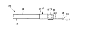
- FIG. 2 is a schematic side view of the wire harness 100 of the embodiment.
- the wire harness 100 includes a plurality of (here, two) electric wires 10, a terminal 20, and a water stop member 30.
- the electric wire 10 is an insulated wire constituted by a core wire 12 made of a conductive material and an insulating coating 14 made of an insulating material covering the periphery of the core wire 12.
- the core wire 12 is formed of a conductive material such as copper, copper alloy, aluminum, or aluminum alloy.
- the insulating coating 14 is made of, for example, polyvinyl chloride (PVC), polyethylene, fluororesin, or polyester.
- a part of the insulating coating 14 near one end is connected by a fusion part 141 of the insulating coating 14. That is, a gap in a part of the gap near one end of the two electric wires 10 and 10 is filled with a fusion portion 141 formed of a fusion product of the insulating coatings 14 and 14.
- the fusion part 141 is a part formed by melting a part of the insulating coatings 14 and 14 of the two electric wires 10 and 10 together with a predetermined solution and solidifying them.
- the terminal 20 is attached to one end of each of the two electric wires 10 and 10.
- the terminal 20 includes a contact portion 21, an intermediate portion 23, and a core wire crimping portion 25.
- the contact part 21 is a part directly connected to the connection partner.
- the contact portion 21 is a flat plate portion, and a through-hole 211 through which a fixing tool (screw or the like) for fixing to a connection partner is passed is formed in the center portion thereof.
- the intermediate part 23 is a part connected to the core wire crimping part 25 and the contact part 21.
- the intermediate part 23 in the present embodiment has a flat plate shape.
- the core wire crimping portion 25 is a core wire connecting portion connected to each of the core wires 12 and 12 of the two electric wires 10 and 10.
- the core wire crimping portion 25 is also a connecting portion that connects the core wires 12 and 12.
- the core wire crimping portion 25 connects the core wires 12 and 12 while being crimped to the end portions of the core wires 12 and 12. It is not essential that the terminal 20 is connected to the core wires 12 and 12 by the core wire crimping portion 25.
- the terminal 20 may be connected to the core wires 12 and 12 by ultrasonic welding, resistance welding, soldering, or the like.
- the structure of the terminal 20 shown in FIGS. 1 and 2 is an example, and the structure of the terminal 20 is not limited to this.
- the shape of the contact portion 21 may be appropriately changed according to the connection partner.
- the terminal 20 may be provided with the coating crimping part crimped
- the wire harness 100 includes a water stop structure that prevents liquid from entering in order to prevent corrosion of the core wire 12.
- the water stop structure in the wire harness 100 includes a water stop member 30.
- the core wire 12 and the insulation coating 14 of the electric wire 10 are made of different metals.
- the core wire 12 is an aluminum wire, that is, a wire (aluminum or aluminum alloy) containing aluminum as a main component.
- the terminal 20 is plated with a tin alloy in which silver (Ag), copper (Cu), bismuth (Bi) or the like is added to tin (Sn) or tin on a copper alloy base material such as copper or brass. It is conceivable that the member has been made.
- the core wire 12 in contact with the terminal 20 is likely to be corroded when a liquid as an electrolyte enters. In such a case, it is effective to attach the water stop member 30 in order to suppress the penetration of the liquid into the core wire crimping portion 25.
- the water stop member 30 covers the periphery of a region (water stop target region) from a portion connected to the core wire crimping portion 25 in the electric wires 10 and 10 to a position overlapping the fusion portion 141 in the electric wires 10 and 10.
- one end of the water stop member 30 extends to a position overlapping the intermediate portion 23, and the water stop member 30 covers the end portions of the core wires 12 and 12 exposed from the insulating coatings 14 and 14. Further, the other end of the water stop member 30 covers up to the middle of the fusion portion 141. A part of the fusion part 141 is exposed outside the water stop member 30.
- the water stop member 30 includes a heat shrinkable tube 31 and a thermoplastic adhesive layer 33 formed on the inner surface of the heat shrinkable tube 31.
- the water stop member 30 is in contact with the water stop target region of the wire harness 100 and covers the water stop target region in a contracted state due to heat.
- the heat-shrinkable tube 31 is bonded to the outer circumferential surface of the core wire crimping portion 25 at one end side without any gap by the adhesive layer 33. Further, the heat shrinkable tube 31 has no gap between the end portions of the insulating coatings 14 and 14 and the outer peripheral surface of a part of the fusion portion 141 connecting them on the other end side by the adhesive layer 33. It is glued.
- the heat-shrinkable tube 31 is formed by, for example, a cylindrical member made of a synthetic resin such as polyolefin resin or nylon resin contracted by heating.
- the adhesive layer 33 is a layer formed by, for example, using a hot-melt adhesive mainly composed of ethylene vinyl acetate (EVA), melting by heating, and then solidifying by cooling.
- EVA ethylene vinyl acetate
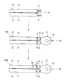
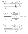
- FIG. 3 and 4 are diagrams showing a manufacturing procedure of the wire harness 100.
- each end portion is in a state in which the insulation coating 14 has been peeled off from the periphery of the core wire 12 of a certain length in advance, that is, the end portion of the core wire 12 of a certain length is Electric wires 10 and 10 processed in a state extending from the end of the insulating coating 14 are prepared (electric wire preparation step S1).
- terminal 20 is connected to one end of the electric wires 10 and 10 (terminal connection step S2). Specifically, the core wire crimping portion 25 of the terminal 20 is crimped to the core wires 12 and 12 at one end of the electric wires 10 and 10, whereby the terminal-attached electric wire 100 ⁇ / b> A is obtained.
- the terminal-attached electric wire 100A has portions where the electric wires 10, 10 extend in parallel with each other, and a slight gap is formed between the insulating coatings 14, 14 of the portions extending in parallel.
- the process which unites a part near one end of the insulation coatings 14 and 14 in the electric wires 10 and 10 is performed (fusion process S3).
- a solution (melt solution M1) for melting the insulating coating 14 is dropped between portions of the parallel insulating coatings 14 and 14 near one end.
- the melt M1 is preferably a ketone, tetrahydrofuran (THF), or the like.
- the molten liquid M1 may be left until it evaporates, or may be wiped off at an appropriate timing.
- the terminal-attached electric wire 100 ⁇ / b> A in which a part of the insulating coatings 14 and 14 are connected by the fusion part 141 is obtained.
- one end of the terminal-attached electric wire 100 ⁇ / b> A is inserted into the water stop member 30 before contraction, and the water stop member 30 is arranged at a position covering the region extending from the intermediate portion 23 to the fusion portion 141.
- the water stop member 30 is heat-processed by the heating apparatus 90 (heating process S4), and the water stop member 30 closely_contact
- the wire harness 100 to which the water stop member 30 is attached is obtained.
- the gap between the two electric wires 10 is formed by fusing part of the insulating coatings 14, 14 near one end without interposing a connecting member (filler) between the two electric wires 10, 10.
- a connecting member filler
- the electric wire 10 has a relatively large diameter because the core wire 12 is formed of aluminum or an aluminum alloy, the electric wires 10 and 10 can be easily connected by the fusion portion 141.
- the gap between the electric wires 10 and 10 is filled with the fusion part 141, and the water stop member 30 is attached so as to overlap the fusion part 141. For this reason, it can reduce that the droplet adhering to the electric wire 10 penetrates the gap of the electric wire 10 and penetrates into the core wire crimping portion 25.
- the fusion portion 141 is arranged inside the water stop member 30, and a portion on the other end side is exposed outside the water stop member 30.
- the edge part of the water stop member 30 can be sealed by the adhesive layer 33 closely_contact
- the water stop member 30 may be formed so as to include the entire fusion portion 141.
- the wire harness 100 includes the two electric wires 10, but may include a larger number of the electric wires 10.
- the water stop member may be formed by winding a resin tape around the water stop target region a plurality of times.
- the water stop member may be a mold resin that is insert-molded with the water stop target region as an insert member.
Landscapes
- Insulated Conductors (AREA)
- Connections Effected By Soldering, Adhesion, Or Permanent Deformation (AREA)
Abstract
複数の電線と端子との接続部分の止水を簡易に実現する技術を提供する。ワイヤーハーネス100は、2本の電線10,10と、端子20と、止水部材30とを備える。電線10,10各々は、導電材料からなる芯線12と、芯線12の周囲を覆う絶縁材料からなる絶縁被覆14とにより構成されている。電線10,10は、一端寄りの絶縁被覆14,14の一部同士の間が、絶縁被覆14,14同士の融合物で形成される融合部141で連結されている。端子20は、導電材料で形成されており、電線10,10各々の一端おいて絶縁被覆14から露出する芯線12に接続されている芯線圧着部25を含む。止水部材30は、電線10,10における芯線接続部25に接続された部分から、電線10,10における融合部141に重なる位置までの周囲を覆う。
Description
この発明は、複数の電線の端部が端子に接続されているワイヤーハーネスに関する。
自動車等の車両に搭載されるワイヤーハーネスにおいて、複数の絶縁電線が電気的に接続される場合、複数の絶縁電線の末端に露出した芯線各々が、端子に接続されることがある。この端子は、例えば、1つの電源に接続されたり、車両の金属フレームなどの基準電位体の1箇所に短絡接続されたりする。
また、ワイヤーハーネスは、芯線接続部への液体の浸入を防ぐ止水構造を備える場合がある。具体的には、端子の芯線接続部の周囲を囲むように熱収縮チューブなどの止水部材が取り付けられる。しかしながら、止水部材によって、複数の電線の隙間を十分に埋めることができない場合、その隙間を通して水分が芯線接続部に進入するおそれがある。そこで、複数の電線の隙間を埋めることが要求されている。
例えば、特許文献1には、電線間に連結部材を介在させ、電線各々をその連結部材に接着させることで一体化する技術が開示されている。
しかしながら、特許文献1の技術の場合、電線を連結部材に一体化させるための加熱処理や、電線を連結部材に押し付ける作業が必要となる。このため、特許文献1の技術を、芯線接続部の止水構造に適用した場合、多大なコスト及び多大な作業時間を要していた。
そこで、本発明は、複数の電線と端子との接続部分の止水を簡易に実現する技術を提供することを目的とする。
上記の課題を解決するため、第1の態様は、ワイヤーハーネスであって、各々が、導電材料からなる芯線と、前記芯線の周囲を覆う絶縁材料からなる絶縁被覆とにより構成されており、一端寄りの前記絶縁被覆の一部同士の間が、前記絶縁被覆同士の融合物で形成される融合部で連結されている、複数本の電線と、導電材料で形成されており、前記複数本の電線各々の前記一端おいて前記絶縁被覆から露出する前記芯線に接続されている芯線接続部を含む端子と、前記複数本の電線における前記芯線接続部に接続された部分から、前記複数本の電線における前記融合部に重なる位置までの周囲を覆う止水部材とを備える。
また、第2の態様は、第1の態様のワイヤーハーネスであって、前記止水部材が、内側に熱可塑性の接着剤の層を含む熱収縮チューブである。
また、第3の態様は、第1または第2の態様のワイヤーハーネスであって、前記絶縁材料が、ポリ塩化ビニルである。
また、第4の態様は、第1から第3の態様のいずれか1つのワイヤーハーネスであって、前記芯線が、アルミニウムまたはアルミニウム合金で形成されている。
第1の態様のワイヤーハーネスによると、複数本の電線における端部寄りの絶縁被覆の一部同士の隙間を、絶縁被覆同士の融合部で連結することで、充填材を間に挟むことなく、複数の電線の端部を容易に一体化できる。また、芯線接続部から融合部に重なる位置までを熱収縮チューブで覆うことによって、止水部材の内側に延びる電線間が融合部で埋められているため、電線間を伝って水分が止水部材の中に侵入することを抑制できる。したがって、芯線接続部を適切に止水できる。
第2の態様のワイヤーハーネスによると、芯線接続部から融合部に重なる位置までを熱収縮チューブで覆うことによって、芯線接続部を適切に止水できる。
第3の態様のワイヤーハーネスによると、絶縁材料がポリ塩化ビニルであるため、絶縁被覆同士を容易に融合できる。
第4の態様のワイヤーハーネスによると、電線の芯線がアルミニウムまたはアルミニウム合金で形成されていることで、電線が太径となっても、電線間を融合部で容易に連結できる。
以下、添付の図面を参照しながら、本発明の実施形態について説明する。なお、この実施形態されている構成要素はあくまでも例示であり、本発明の範囲をそれらのみに限定する趣旨のものではない。また、図面においては、理解容易のため、必要に応じて各部の寸法や数が誇張または簡略化して図示されている場合がある。
<1. 実施形態>
図1は、実施形態のワイヤーハーネス100の概略平面図である。図2は、実施形態のワイヤーハーネス100の概略側面図である。
図1は、実施形態のワイヤーハーネス100の概略平面図である。図2は、実施形態のワイヤーハーネス100の概略側面図である。
ワイヤーハーネス100は、複数本(ここでは、2本)の電線10と、端子20と、止水部材30とを備える。
<電線>
電線10は、導電材料からなる芯線12と、芯線12の周囲を覆う絶縁材料からなる絶縁被覆14とにより構成された絶縁電線である。芯線12は、銅、銅合金、アルミニウムまたはアルミニウム合金などの導電性材料で形成されている。絶縁被覆14は、例えば、ポリ塩化ビニル(PVC)、ポリエチレン、フッ素樹脂またはポリエステル等で形成されている。
電線10は、導電材料からなる芯線12と、芯線12の周囲を覆う絶縁材料からなる絶縁被覆14とにより構成された絶縁電線である。芯線12は、銅、銅合金、アルミニウムまたはアルミニウム合金などの導電性材料で形成されている。絶縁被覆14は、例えば、ポリ塩化ビニル(PVC)、ポリエチレン、フッ素樹脂またはポリエステル等で形成されている。
2本の電線10,10において、一端寄りの絶縁被覆14の一部同士の間が、絶縁被覆14の融合部141で連結されている。すなわち、2本の電線10,10の一端寄りの一部の隙間は、絶縁被覆14,14同士の融合物で形成される融合部141によって隙間が埋められている。融合部141は、2本の電線10,10の双方の絶縁被覆14、14の一部を所定の溶液で融かし合わせ、これを固化させることによって形成された部分である。
<端子>
端子20は、2本の電線10,10各々の一端部に取り付けられている。端子20は、接点部21、中間部23及び芯線圧着部25を有している。
端子20は、2本の電線10,10各々の一端部に取り付けられている。端子20は、接点部21、中間部23及び芯線圧着部25を有している。
接点部21は、接続相手に直接接続される部分である。接点部21は、ここでは、平板状の部分であり、その中央部に、接続相手に固定するための固定具(ネジ等)が通される貫通孔211が形成されている。
中間部23は、芯線圧着部25と接点部21とに連なる部分である。本実施形態における中間部23は平板状である。
芯線圧着部25は、2本の電線10,10の芯線12,12各々に接続される芯線接続部である。芯線圧着部25は、芯線12,12各々を連結する連結部でもある。芯線圧着部25は、芯線12,12の端部に圧着された状態で芯線12,12を連結する。なお、端子20が、芯線12,12に対して、芯線圧着部25で接続されることは必須ではない。例えば、端子20が芯線12,12に対して超音波溶接、抵抗溶接、または、半田付け等で接続されてもよい。
図1及び図2が示す端子20の構造は一例であって、端子20の構造はこれに限定されるものではない。例えば、接点部21の形状は、接続相手に合わせて適宜変更してよい。また、端子20が、2本の電線10,10の絶縁被覆14、14各々の一端寄りの一部に圧着される被覆圧着部を備えていてもよい。
<止水部材>
ワイヤーハーネス100は、芯線12の腐食を防ぐために液体の浸入を防ぐ止水構造を備えている。ワイヤーハーネス100における止水構造は、止水部材30を含む。
ワイヤーハーネス100は、芯線12の腐食を防ぐために液体の浸入を防ぐ止水構造を備えている。ワイヤーハーネス100における止水構造は、止水部材30を含む。
ワイヤーハーネス100において、電線10の芯線12と絶縁被覆14とが、それぞれ異種の金属で構成されていることが考えられる。例えば、芯線12が、アルミニウム線、即ち、アルミニウムを主成分とする金属(アルミニウムまたはアルミニウム合金)の線材であることが考えられる。一方、端子20が、銅もしくは黄銅などの銅合金の基材に、錫(Sn)もしくは錫に銀(Ag)、銅(Cu)、ビスマス(Bi)などが添加された錫合金のメッキが施された部材であることが考えられる。この場合、端子20と接触する芯線12は、電解液となる液体が浸入すると腐食しやすい。このような場合、芯線圧着部25への液体の侵入を抑制するため、止水部材30を取付けることは有効である。
止水部材30は、電線10,10における芯線圧着部25に接続された部分から、電線10,10における融合部141に重なる位置までの領域(止水対象領域)の周囲を覆う。ここでは、止水部材30の一端は中間部23に重なる位置まで延びており、止水部材30は、絶縁被覆14,14から露出した芯線12,12各々の端部を覆っている。また、止水部材30の他端は融合部141の途中までを覆っている。融合部141の一部が止水部材30の外側に露出している。
止水部材30は、熱収縮チューブ31及びその熱収縮チューブ31の内側面に形成された熱可塑性の接着剤層33を備える。止水部材30は、熱を受けて収縮した状態で、ワイヤーハーネス100の止水対象領域に密着して、その止水対象領域を覆っている。
熱収縮チューブ31は、一端側おいて、芯線圧着部25の外周面の全周方向に亘り、接着剤層33によって隙間無く接着されている。また、熱収縮チューブ31は、他端側において、絶縁被覆14,14の端部と、それらを連結する融合部141の一部の外周面の全周方向に亘り、接着剤層33によって隙間無く接着されている。
熱収縮チューブ31は、例えば、ポリオレフィン系樹脂もしくはナイロン系樹脂等の合成樹脂からなる筒状の部材が、加熱によって収縮したものである。接着剤層33は、例えば、エチレン酢酸ビニル(EVA)を主成分とするホットメルト接着剤が用いられ、加熱によって溶融した後、冷えて固化することによって形成される層である。
<製造方法>
次に、ワイヤーハーネス100の製造手順について説明する。図3及び図4は、ワイヤーハーネス100の製造手順を示す図である。
次に、ワイヤーハーネス100の製造手順について説明する。図3及び図4は、ワイヤーハーネス100の製造手順を示す図である。
まず、図3が示すように、各々の端部が、予め一定の長さの分の芯線12の周囲から絶縁被覆14が剥がれた状態、すなわち、一定の長さ分の芯線12の端部が絶縁被覆14の端から延び出た状態に加工された電線10,10が準備される(電線準備工程S1)。
続いて、電線10,10の一端に端子20が接続される(端子接続工程S2)。詳細には、電線10,10の一端の芯線12,12に、端子20の芯線圧着部25が圧着されることで、端子付電線100Aが得られる。この端子付電線100Aは、電線10,10が互いに平行に延びる部分を有しており、その平行に延びる部分の絶縁被覆14,14間にはわずかに隙間が形成されている。
続いて、電線10,10における絶縁被覆14,14の一端寄りの一部を融合する処理が行われる(融合工程S3)。具体的には、平行する絶縁被覆14,14のうち一端寄りの部分間に、絶縁被覆14を溶融する溶液(溶融液M1)が滴下される。溶融液M1は、絶縁被覆14がPVCである場合、ケトン類、テトラフドロフラン(THF)等が好適である。溶融液M1は、蒸発するまで放置してもよいし、適宜のタイミングで拭き取られてもよい。これによって、図4に示すように、絶縁被覆14,14の一部が融合部141で連結された端子付電線100Aが得られる。
続いて、端子付電線100Aの一端部が収縮前の止水部材30に挿入され、止水部材30が中間部23から融合部141に亘る領域を覆う位置に配される。そして、加熱装置90によって止水部材30が加熱処理される(加熱工程S4)ことによって、止水部材30が端子付電線100Aに密着する。これによって、止水部材30が取付けられたワイヤーハーネス100が得られる。
<効果>
ワイヤーハーネス100においては、2本の電線10,10間に連結部材(充填材)を介在させることなく、絶縁被覆14,14の一端寄りの一部を融合させることによって2本の電線10を隙間無く連結できる。このため、複数本の電線の連結を低コスト且つ簡便に行うことができる。また、電線の本数が3本以上に増大しても、容易に対応できる。
ワイヤーハーネス100においては、2本の電線10,10間に連結部材(充填材)を介在させることなく、絶縁被覆14,14の一端寄りの一部を融合させることによって2本の電線10を隙間無く連結できる。このため、複数本の電線の連結を低コスト且つ簡便に行うことができる。また、電線の本数が3本以上に増大しても、容易に対応できる。
また、芯線12がアルミニウムまたはアルミニウム合金で形成されていることで電線10が比較的太径となっても、電線10,10間を融合部141によって容易に連結できる。
ワイヤーハーネス100においては、電線10,10間の隙間が融合部141で埋められ、この融合部141に重なるように止水部材30が取付けられている。このため、電線10に付着した液滴が、電線10の隙間を伝って、芯線圧着部25にまで侵入することを低減できる。
ワイヤーハーネス100においては、融合部141の一端側の部分が止水部材30の内側に配され、他端側の部分が止水部材30の外側に露出している。これによって、止水部材30の端部において、接着剤層33が融合部141に密着することで、止水部材30の端部を密封でき、効果的に止水できる。ただし、止水部材30は、融合部141の全部を含むように形成されていてもよい。
<2. 変形例>
以上、実施形態について説明してきたが、本発明は上記のようなものに限定されるものではなく、様々な変形が可能である。
以上、実施形態について説明してきたが、本発明は上記のようなものに限定されるものではなく、様々な変形が可能である。
例えば、ワイヤーハーネス100は、2本の電線10を備えるが、より多くの本数の電線10を備えていてもよい。
また、止水部材は、止水対象領域に樹脂製のテープを複数回巻くことによって形成されたものとしてもよい。また、止水部材は、止水対象領域をインサート部材としてインサート成形されたモールド樹脂であってもよい。
この発明は詳細に説明されたが、上記の説明は、すべての局面において、例示であって、この発明がそれに限定されるものではない。例示されていない無数の変形例が、この発明の範囲から外れることなく想定され得るものと解される。また、上記各実施形態及び各変形例で説明した各構成は、相互に矛盾しない限り適宜組み合わせたり、省略したりすることができる。
100 ワイヤーハーネス
100A 端子付電線
10 電線
12 芯線
14 絶縁被覆
141 融合部
20 端子
25 芯線圧着部(芯線接続部)
30 止水部材
31 熱収縮チューブ
33 接着剤層
M1 溶融液
100A 端子付電線
10 電線
12 芯線
14 絶縁被覆
141 融合部
20 端子
25 芯線圧着部(芯線接続部)
30 止水部材
31 熱収縮チューブ
33 接着剤層
M1 溶融液
Claims (4)
- ワイヤーハーネスであって、
各々が、導電材料からなる芯線と、前記芯線の周囲を覆う絶縁材料からなる絶縁被覆とにより構成されており、一端寄りの前記絶縁被覆の一部同士の間が、前記絶縁被覆同士の融合物で形成される融合部で連結されている、複数本の電線と、
導電材料で形成されており、前記複数本の電線各々の前記一端おいて前記絶縁被覆から露出する前記芯線に接続されている芯線接続部を含む端子と、
前記複数本の電線における前記芯線接続部に接続された部分から、前記複数本の電線における前記融合部に重なる位置までの周囲を覆う止水部材と、
を備える、ワイヤーハーネス。 - 請求項1のワイヤーハーネスであって、
前記止水部材が、内側に熱可塑性の接着剤の層を含む熱収縮チューブである、ワイヤーハーネス。 - 請求項1または請求項2のワイヤーハーネスであって、
前記絶縁材料が、ポリ塩化ビニルである、ワイヤーハーネス。 - 請求項1から請求項3のいずれか1項のワイヤーハーネスであって、
前記芯線が、アルミニウムまたはアルミニウム合金で形成されている、ワイヤーハーネス。
Applications Claiming Priority (2)
| Application Number | Priority Date | Filing Date | Title |
|---|---|---|---|
| JP2016-067718 | 2016-03-30 | ||
| JP2016067718A JP2017183042A (ja) | 2016-03-30 | 2016-03-30 | ワイヤーハーネス |
Publications (1)
| Publication Number | Publication Date |
|---|---|
| WO2017169759A1 true WO2017169759A1 (ja) | 2017-10-05 |
Family
ID=59965212
Family Applications (1)
| Application Number | Title | Priority Date | Filing Date |
|---|---|---|---|
| PCT/JP2017/010315 Ceased WO2017169759A1 (ja) | 2016-03-30 | 2017-03-15 | ワイヤーハーネス |
Country Status (2)
| Country | Link |
|---|---|
| JP (1) | JP2017183042A (ja) |
| WO (1) | WO2017169759A1 (ja) |
Cited By (2)
| Publication number | Priority date | Publication date | Assignee | Title |
|---|---|---|---|---|
| CN112092355A (zh) * | 2019-07-11 | 2020-12-18 | 铜陵博康机电有限公司 | 一种线束端部与热缩管成型装置的操作方法 |
| CN113067229A (zh) * | 2021-03-29 | 2021-07-02 | 金华市正通线缆有限公司 | 增加安全性能及使用寿命的多芯护套线的制作方法 |
Families Citing this family (2)
| Publication number | Priority date | Publication date | Assignee | Title |
|---|---|---|---|---|
| JP7065514B2 (ja) * | 2018-07-10 | 2022-05-12 | 株式会社アイエイアイ | ワイヤーハーネスとワイヤーハーネス製造方法 |
| WO2026009519A1 (ja) * | 2024-07-05 | 2026-01-08 | 住友電工ファインポリマー株式会社 | 端子付き電線 |
Citations (3)
| Publication number | Priority date | Publication date | Assignee | Title |
|---|---|---|---|---|
| JP2013026018A (ja) * | 2011-07-21 | 2013-02-04 | Auto Network Gijutsu Kenkyusho:Kk | 電線束 |
| JP2014229586A (ja) * | 2013-05-27 | 2014-12-08 | 株式会社オートネットワーク技術研究所 | ワイヤハーネス |
| JP2014232619A (ja) * | 2013-05-29 | 2014-12-11 | 株式会社オートネットワーク技術研究所 | 端子付電線 |
-
2016
- 2016-03-30 JP JP2016067718A patent/JP2017183042A/ja active Pending
-
2017
- 2017-03-15 WO PCT/JP2017/010315 patent/WO2017169759A1/ja not_active Ceased
Patent Citations (3)
| Publication number | Priority date | Publication date | Assignee | Title |
|---|---|---|---|---|
| JP2013026018A (ja) * | 2011-07-21 | 2013-02-04 | Auto Network Gijutsu Kenkyusho:Kk | 電線束 |
| JP2014229586A (ja) * | 2013-05-27 | 2014-12-08 | 株式会社オートネットワーク技術研究所 | ワイヤハーネス |
| JP2014232619A (ja) * | 2013-05-29 | 2014-12-11 | 株式会社オートネットワーク技術研究所 | 端子付電線 |
Cited By (3)
| Publication number | Priority date | Publication date | Assignee | Title |
|---|---|---|---|---|
| CN112092355A (zh) * | 2019-07-11 | 2020-12-18 | 铜陵博康机电有限公司 | 一种线束端部与热缩管成型装置的操作方法 |
| CN112092355B (zh) * | 2019-07-11 | 2023-04-07 | 铜陵博康机电有限公司 | 一种线束端部与热缩管成型装置的操作方法 |
| CN113067229A (zh) * | 2021-03-29 | 2021-07-02 | 金华市正通线缆有限公司 | 增加安全性能及使用寿命的多芯护套线的制作方法 |
Also Published As
| Publication number | Publication date |
|---|---|
| JP2017183042A (ja) | 2017-10-05 |
Similar Documents
| Publication | Publication Date | Title |
|---|---|---|
| US9356438B2 (en) | Wire cable assembly having a terminal with an encapsulated wire end | |
| WO2017169759A1 (ja) | ワイヤーハーネス | |
| JP5369637B2 (ja) | 端子金具付き電線及びその製造方法 | |
| JP2015015207A (ja) | 端子金具及びワイヤーハーネス | |
| US20170169919A1 (en) | Wire harness and method for manufacturing same | |
| JP2002008791A (ja) | シールドコネクタ及びその製造方法 | |
| JP6996974B2 (ja) | 端子付き電線および端子付き電線の製造方法 | |
| JP2022003644A (ja) | 端子付電線及び端子付電線の製造方法 | |
| JP2017084600A (ja) | 端子付電線及び端子付電線の製造方法 | |
| JP5962589B2 (ja) | 端子付電線 | |
| JP5589779B2 (ja) | 端子金具付き電線、及び端子金具付き電線の製造方法 | |
| JP2012185984A (ja) | 端子金具付き電線 | |
| US10065342B2 (en) | Molded resin-equipped electric wire and molded resin-equipped electric wire production method | |
| JP2014203725A (ja) | 端子付電線 | |
| JP2014007030A (ja) | 端子付き電線 | |
| JP2017091642A (ja) | 電線モジュール製造方法及び電線モジュール | |
| WO2015108011A1 (ja) | 端子および該端子の電線接続構造 | |
| JP2014229586A (ja) | ワイヤハーネス | |
| KR101526179B1 (ko) | 와이어홀더를 이용한 전선의 방수 장치 | |
| CN110690585B (zh) | 带端子的电线及其制造方法 | |
| JP2014229574A (ja) | ワイヤハーネスの製造方法及びワイヤハーネス | |
| JP5778197B2 (ja) | 電線接続構造体及び電線 | |
| JP5823439B2 (ja) | 被覆電線、接続構造体、コネクタ、並びに、被覆電線の製造方法、接続構造体の製造方法 | |
| CN113478073B (zh) | 线缆的密封加工方法和摄像机 | |
| JP2017091643A (ja) | 電線モジュール製造方法及び電線モジュール |
Legal Events
| Date | Code | Title | Description |
|---|---|---|---|
| NENP | Non-entry into the national phase |
Ref country code: DE |
|
| 121 | Ep: the epo has been informed by wipo that ep was designated in this application |
Ref document number: 17774303 Country of ref document: EP Kind code of ref document: A1 |
|
| 122 | Ep: pct application non-entry in european phase |
Ref document number: 17774303 Country of ref document: EP Kind code of ref document: A1 |