WO2017169625A1 - 回転式電子部品 - Google Patents
回転式電子部品 Download PDFInfo
- Publication number
- WO2017169625A1 WO2017169625A1 PCT/JP2017/009460 JP2017009460W WO2017169625A1 WO 2017169625 A1 WO2017169625 A1 WO 2017169625A1 JP 2017009460 W JP2017009460 W JP 2017009460W WO 2017169625 A1 WO2017169625 A1 WO 2017169625A1
- Authority
- WO
- WIPO (PCT)
- Prior art keywords
- shaft
- contact
- encoder
- electronic component
- contact member
- Prior art date
- Legal status (The legal status is an assumption and is not a legal conclusion. Google has not performed a legal analysis and makes no representation as to the accuracy of the status listed.)
- Ceased
Links
Images








Classifications
-
- H—ELECTRICITY
- H01—ELECTRIC ELEMENTS
- H01H—ELECTRIC SWITCHES; RELAYS; SELECTORS; EMERGENCY PROTECTIVE DEVICES
- H01H25/00—Switches with compound movement of handle or other operating part
- H01H25/06—Operating part movable both angularly and rectilinearly, the rectilinear movement being along the axis of angular movement
-
- H—ELECTRICITY
- H01—ELECTRIC ELEMENTS
- H01H—ELECTRIC SWITCHES; RELAYS; SELECTORS; EMERGENCY PROTECTIVE DEVICES
- H01H19/00—Switches operated by an operating part which is rotatable about a longitudinal axis thereof and which is acted upon directly by a solid body external to the switch, e.g. by a hand
- H01H19/02—Details
- H01H19/10—Movable parts; Contacts mounted thereon
- H01H19/11—Movable parts; Contacts mounted thereon with indexing means
-
- H—ELECTRICITY
- H01—ELECTRIC ELEMENTS
- H01H—ELECTRIC SWITCHES; RELAYS; SELECTORS; EMERGENCY PROTECTIVE DEVICES
- H01H19/00—Switches operated by an operating part which is rotatable about a longitudinal axis thereof and which is acted upon directly by a solid body external to the switch, e.g. by a hand
- H01H19/005—Electromechanical pulse generators
-
- H—ELECTRICITY
- H01—ELECTRIC ELEMENTS
- H01H—ELECTRIC SWITCHES; RELAYS; SELECTORS; EMERGENCY PROTECTIVE DEVICES
- H01H19/00—Switches operated by an operating part which is rotatable about a longitudinal axis thereof and which is acted upon directly by a solid body external to the switch, e.g. by a hand
- H01H19/005—Electromechanical pulse generators
- H01H2019/006—Electromechanical pulse generators being rotation direction sensitive, e.g. the generated pulse or code depends on the direction of rotation of the operating part
-
- H—ELECTRICITY
- H01—ELECTRIC ELEMENTS
- H01H—ELECTRIC SWITCHES; RELAYS; SELECTORS; EMERGENCY PROTECTIVE DEVICES
- H01H2215/00—Tactile feedback
- H01H2215/03—Sound
-
- H—ELECTRICITY
- H01—ELECTRIC ELEMENTS
- H01H—ELECTRIC SWITCHES; RELAYS; SELECTORS; EMERGENCY PROTECTIVE DEVICES
- H01H2221/00—Actuators
- H01H2221/008—Actuators other then push button
- H01H2221/01—Actuators other then push button also rotatable
-
- H—ELECTRICITY
- H01—ELECTRIC ELEMENTS
- H01H—ELECTRIC SWITCHES; RELAYS; SELECTORS; EMERGENCY PROTECTIVE DEVICES
- H01H2223/00—Casings
- H01H2223/008—Casings metallic
-
- H—ELECTRICITY
- H01—ELECTRIC ELEMENTS
- H01H—ELECTRIC SWITCHES; RELAYS; SELECTORS; EMERGENCY PROTECTIVE DEVICES
- H01H2225/00—Switch site location
- H01H2225/004—Switch site location in different planes to increase density
-
- H—ELECTRICITY
- H01—ELECTRIC ELEMENTS
- H01H—ELECTRIC SWITCHES; RELAYS; SELECTORS; EMERGENCY PROTECTIVE DEVICES
- H01H2225/00—Switch site location
- H01H2225/03—Different type of switches
-
- H—ELECTRICITY
- H01—ELECTRIC ELEMENTS
- H01H—ELECTRIC SWITCHES; RELAYS; SELECTORS; EMERGENCY PROTECTIVE DEVICES
- H01H2239/00—Miscellaneous
- H01H2239/026—Internal encoding, e.g. validity bit
Definitions
- the present invention relates to a rotary electronic component.
- the rotary electronic component includes a shaft, a regulating member that regulates the rotation angle of the shaft, and an encoder mechanism that detects the rotation direction and the rotation angle of the shaft.
- the conventional rotary electronic component encoder mechanism has a rotor attached to the shaft and a slider attached to the rotor.
- the restricting member contacts the outer peripheral surface of the rotor and restricts the rotation angle of the shaft.
- the regulating member regulates the rotation angle of the shaft by bringing a ball into contact with the outer peripheral surface of the rotor. Specifically, the ball pressed by the restricting member enters the concave portion on the outer periphery of the rotor and is pressed and held. In the case of downsizing with this structure, high processing accuracy and assembly accuracy of each part are necessary, and it is difficult to realize. It is also difficult to ensure reliability.
- an object of the present invention is to provide a rotary electronic component that can be miniaturized.
- the rotary electronic component of the present invention is A base member; A shaft attached to the base member so as to be rotatable about an axis; A regulating member that regulates the rotation angle of the shaft;
- the shaft has a collar portion including a plurality of convex portions and concave portions alternately arranged in the circumferential direction,
- the regulating member is A contact member that contacts the convex part and the concave part of the shaft; A biasing member that biases the contact member from the radially outer side of the shaft toward the shaft.
- the contact member of the regulating member is urged by the urging member from the radially outer side of the shaft toward the shaft side, and is urged to the convex portion of the shaft flange. While contacting, it fits into the recess of the flange of the shaft to regulate the rotation angle of the shaft.
- the regulating member that regulates the rotation angle of the shaft can be reduced in size with a simple configuration, and as a result, the rotary electronic component can be reduced in size.
- a miniaturized rotary encoder can be provided by providing an encoder mechanism for detecting the rotational direction and rotational angle of the shaft.
- a switch mechanism that is pressed against the shaft by movement along the shaft axis may be provided, and the shaft can be used for both the rotation angle regulating operation and the axial switch operation.
- One end of the contact member is rotatably connected to the base member, and the other end is a free end that contacts the convex portion and the concave portion of the shaft, The urging member is locked to the free end side of the contact member.
- one end of the contact member is rotatably connected to the base member, and the other end of the contact member is a free end that contacts the convex portion and the concave portion of the shaft, and the free end side of the contact member is Since the urging member is locked, the free end of the contact member is constrained to rotate on the arc, and the behavior of the contact member accompanying the rotation of the shaft is stabilized. Thereby, a smooth click feeling is obtained.
- the contact member of the regulating member has a first contact member and a second contact member arranged on both sides of the shaft,
- the biasing member of the regulating member is An elastically deformable base; A first locking portion provided at one end of the base so as to lock to the free end side of the first contact member; And a second locking portion provided at the other end of the base portion so as to be locked to the free end side of the second contact member.
- the biasing member having the elastically deformable base portion and the first and second locking portions locked to the free end sides of the first and second contact members allows the first member of the restricting member.
- the first and second contact members are urged toward the shaft side from the outside in the radial direction of the shaft and come into contact with the convex and concave portions of the flange from both sides of the shaft. A smooth click feeling is obtained as well.
- the first contact member and the second contact member of the restricting member are arranged in plane symmetry with respect to a plane passing through the shaft axis.
- the first contact member and the second contact member of the restricting member are arranged in a plane-symmetrical position with respect to a plane passing through the axis of the shaft.
- the contact state with respect to the convex portion and the concave portion of the flange portion of the shaft is synchronized, so that a smoother click feeling is obtained.
- the convex portion of the flange portion of the shaft is disposed at a plane symmetric with respect to a plane passing through the axis of the shaft,
- the concave portion of the flange portion of the shaft is disposed at a plane symmetric with respect to a plane passing through the shaft axis.
- the convex portion of the flange portion of the shaft is disposed in a plane-symmetrical position with respect to the plane passing through the axis of the shaft, and the concave portion of the flange portion of the shaft is in a plane passing through the shaft axis. Since the first contact member and the second contact member are arranged in plane symmetry with respect to each other, the contact state with respect to the convex portion and the concave portion of the flange portion of the shaft is synchronized, so that a smoother click feeling is obtained. It is done.
- the urging member of the restricting member is held by the base member so as to be movable as a whole within a predetermined range.
- the urging member of the restricting member is held by the base member so that the entire urging member can move within a predetermined range.
- the contact member and the biasing member of the regulating member are locked by curved surfaces that contact each other.
- the contact area between the contact member and the urging member can be increased by locking the contact member and the urging member of the regulating member with the curved surfaces that are in contact with each other.
- the surface pressure decreases, the wear on the contact surface between the contact member and the biasing member can be reduced, and the reliability can be improved.
- a movement restricting member for restricting movement of the restricting member in the axial direction of the shaft is provided.
- the behavior of the restricting member is not disturbed in the axial direction of the shaft as the shaft rotates.
- the regulating member that regulates the rotation angle of the shaft can be reduced in size with a simple configuration. As a result, the rotary electronic component can be reduced in size.
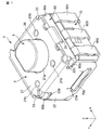
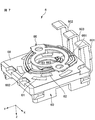
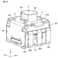
- FIG. 1 is a perspective view seen from above a rotary encoder 1 as an example of a rotary electronic component according to an embodiment of the present invention.
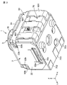
- FIG. 2 is a perspective view of the rotary encoder 1 as viewed from below.
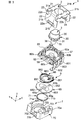
- FIG. 3 is an exploded perspective view of the rotary encoder 1 as viewed from above.
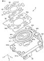
- FIG. 4 is an exploded perspective view of the rotary encoder 1 as viewed from below.
- FIG. 5 is a sectional view of the rotary encoder 1.
- the width direction of the rotary encoder 1 is defined as the X direction
- the length direction of the rotary encoder 1 is defined as the Y direction
- the height direction of the rotary encoder 1 is taken as the Z direction.
- the positive direction in the Z direction is the upper side
- the negative direction in the Z direction is the lower side.
- the rotary encoder 1 includes a casing 2, a shaft 3 attached to the casing 2 so as to be rotatable about the axis and movable along the axis, and the shaft 3.
- a regulating member click spring 55, pendulum 56, 57
- the regulating member click spring 55, pendulum 56, 57
- encoder mechanism 6 and switch mechanism 7 are arranged along the axis of the shaft 3 in order from the upper side to the lower side.
- the click spring 55 is an example of a contact member.
- the pendulum 56 is an example of a first contact member
- the pendulum 57 is an example of a second contact member.
- Casing 2 is made of metal, for example.
- the shaft 3 In the casing 2, the shaft 3, the regulating member (click spring 55, pendulum 56, 57), the encoder mechanism 6, and the switch mechanism 7 are assembled together.
- the casing 2 includes an upper wall 21, side walls 22, 22 provided on both sides of the upper wall 21 in the X direction and extending downward, and a protruding wall provided in the positive direction of the upper wall 21 in the Y direction and extending downward. 23 and a protruding piece 24 provided in the negative direction of the upper wall 21 in the Y direction and extending downward.
- the upper wall 21 has one hole 21a and four recesses 21b around the hole 21a.
- the side wall 22 has a hole 22a on the lower side and a groove 22b on the upper side.
- a locking portion 22c that protrudes inside the casing 2 is provided.
- the protruding wall 23 extends over the entire length of the upper wall 21 in the X direction.
- the projecting piece 24 is provided at the center of the upper wall 21 in the X direction.
- the shaft 3 is made of, for example, resin.
- the shaft 3 includes an operation portion 35, a gear-shaped flange portion 30, and an end portion 36.
- the operation part 35, the gear-shaped flange part 30, and the end part 36 are arranged in order from the upper side to the lower side along the axis.
- the operation unit 35 has a notch that serves as a mark for the rotation of the shaft 3.
- the gear-shaped collar part 30 includes a plurality of convex parts 31 and concave parts 32.
- the plurality of convex portions 31 and concave portions 32 are alternately arranged in the circumferential direction.
- the operation unit 35 penetrates the hole 21 a of the upper wall 21 of the casing 2, and the user can operate the operation unit 35 from the outside of the casing 2.
- the encoder mechanism 6 includes an encoder board 60 as an example of a base member, resistor patterns 61, 62, and 63 provided on the encoder board 60, and an encoder board 60 that is electrically connected to the resistor patterns 61, 62, and 63.
- Encoder terminals 601, 602, and 603 that are connected to each other, a rotor 65 that is attached to the shaft 3 so as to be rotatable together with the shaft 3, and a slide that is attached to the rotor 65 and slidably contacts the resistor patterns 61, 62, and 63.
- a mover 66 is an encoder board 60 as an example of a base member, resistor patterns 61, 62, and 63 provided on the encoder board 60, and an encoder board 60 that is electrically connected to the resistor patterns 61, 62, and 63.
- Encoder terminals 601, 602, and 603 that are connected to each other, a rotor 65 that is attached to the shaft 3 so as to be
- the encoder board 60 is made of resin, for example.
- a regulating member (click spring 55, pendulum 56, 57) is attached to the upper surface 60a of the encoder board 60.
- Protrusions 60b are provided on both sides of the encoder board 60 in the X direction.
- the protrusion 60 b is fitted in the groove 22 b of the side wall 22 of the casing 2.
- Both sides of the encoder board 60 in the Y direction are sandwiched between the protruding wall 23 and the protruding piece 24.
- the encoder board 60 is fixed to the casing 2 by the groove 22b of the side wall 22, the protruding wall 23, and the protruding piece 24.
- the groove portion 22 b of the side wall 22, the protruding wall 23, and the protruding piece 24 constitute an encoder fixing portion that fixes the encoder board 60.
- Resistor patterns 61, 62, and 63 are provided on the lower surface of the encoder board 60.
- the resistor patterns 61, 62, and 63 are for detecting the rotation direction and rotation angle of the shaft 3.
- the first resistor pattern 61, the second resistor pattern 62, and the third resistor pattern 63 are formed in an annular shape and arranged concentrically.
- the first resistor pattern 61, the second resistor pattern 62, and the third resistor pattern 63 are sequentially arranged from the outer side to the inner side in the radial direction.
- the first resistor pattern 61 and the second resistor pattern 62 are each formed intermittently.
- the third resistor pattern 63 is formed continuously.
- Encoder terminals 601, 602, and 603 are insert-molded on the encoder board 60.
- the first encoder terminal 601 is electrically connected to the first resistor pattern 61
- the second encoder terminal 602 is electrically connected to the second resistor pattern 62
- the third encoder terminal 603 is a third resistor.
- the body pattern 63 is electrically connected.
- the rotor 65 is positioned in the circumferential direction with respect to the shaft 3 and is movable in the axial direction. More specifically, the rotor 65 has a D-shaped hole 65a. The outer peripheral surface of the end portion 36 of the shaft 3 is formed in a D shape. The D-shaped end portion 36 is fitted into the D-shaped hole 65a, so that the rotor 65 is fixed to the shaft 3 in the circumferential direction and is not fixed in the axial direction.
- the rotor 65 is formed in a substantially oval shape.
- the rotor 65 has a long diameter portion 651 in which the outer diameter of the rotor 65 is a long diameter, and a short diameter portion 652 in which the outer diameter of the rotor 65 is a short diameter.
- the length of the long diameter portion 651 is larger than the gap between the locking portions 22c of the opposite side walls 22, and the length of the short diameter portion 652 is smaller than the gap between the locking portions 22c of the opposite side walls 22.
- the locking portion 22 c is configured such that the short diameter portion 652 is detached without locking and the long diameter portion 651 can be engaged and disengaged by the rotation of the rotor 65.
- the slider 66 is made of metal, for example.
- the slider 66 is fixed to the two protrusions 65 b on the upper surface of the rotor 65.
- the slider 66 is formed in an annular shape.
- the slider 66 has a first contact portion 661, a second contact portion 662, and a third contact portion 663.
- the first contact portion 661, the second contact portion 662, and the third contact portion 663 are sequentially arranged from the outer side to the inner side in the radial direction.
- the first contact part 661, the second contact part 662, and the third contact part 663 are electrically connected.
- the first contact portion 661 can contact the first resistor pattern 61
- the second contact portion 662 can contact the second resistor pattern 62
- the third contact portion 663 can contact the third resistor pattern 63. It becomes possible to contact.
- the switch mechanism 7 includes a switch board 70, first to third switch terminals 701, 702, and 703 provided on the switch board 70, and a conductor provided on the switch board 70 and pressed against the end portion 36 of the shaft 3. 71.
- the conductor 71 is electrically connected to the first and second switch terminals 701 and 702.
- the conductor 71 is pressed by the end portion 36 of the shaft 3 and is electrically connected to the third switch terminal 703 to conduct the first and second switch terminals 701 and 702 and the third switch terminal 703.
- the switch signal is turned on.
- each function operates when the switch signal is turned on. Note that only one of the first and second switch terminals 701 and 702 may be provided.
- Projections 70b are provided on both sides of the switch board 70 in the X direction.
- the protrusion 70 b is fitted in the hole 22 a of the side wall 22 of the casing 2.
- the switch board 70 is fixed to the casing 2 by the hole 22 a of the side wall 22.
- the hole 22 a of the side wall 22 constitutes a switch fixing portion that fixes the switch substrate 70.
- a stepped portion 70c is provided on one side of the lower surface of the switch substrate 70 in the X direction. End portions of the bent encoder terminals 601, 602, and 603 are locked to the stepped portion 70c. That is, the encoder board 60 and the switch board 70 are integrally held by the bent encoder terminals 601, 602, and 603.
- the depth of the stepped portion 70c is deeper than the thickness of the encoder terminals 601, 602, 603.
- the first to third switch terminals 701, 702, and 703 are insert-molded on the switch board 70.
- the third switch terminal 703 is located between the first switch terminal 701 and the second switch terminal 702.
- the conductor 71 has elasticity.
- the conductor 71 is formed in a dome shape.
- the conductor 71 is fitted in the recess 70 a on the upper surface of the switch substrate 70.
- the peripheral portion 71 a of the conductor 71 is electrically connected to the first and second switch terminals 701 and 702.
- the zenith portion 71 b of the conductor 71 is separated from the third switch terminal 703 in the free state of the conductor 71, while being pressed by the end portion 36 of the shaft 3 and electrically connected to the third switch terminal 703.
- the end portion 36 of the shaft 3 presses the zenith portion 71 b of the conductor 71, and the zenith portion 71 b of the conductor 71 is electrically connected to the third switch terminal 703. Is done.
- the first and second switch terminals 701 and 702 and the third switch terminal 703 are electrically connected, and the switch signal is turned on.
- the conductor 71 returns to the free state, so that the shaft 3 moves upward, and the zenith portion 71b of the conductor 71 is separated from the third switch terminal 703. .
- the first and second switch terminals 701 and 702 and the third switch terminal 703 are not electrically connected, and the switch signal is turned off.
- FIG. 6 is an exploded perspective view of the encoder mechanism 6 as viewed from below.
- first, second, and third electrode portions 671, 672, and 673 are provided on the lower surface of the encoder substrate 60.
- the 1st electrode part 671, the 2nd electrode part 672, and the 3rd electrode part 673 are formed in an annular shape, and are arranged concentrically.
- the 1st electrode part 671, the 2nd electrode part 672, and the 3rd electrode part 673 are arranged in order from the outside in the diameter direction to the inside.
- the first electrode portion 671 is electrically connected to the end portion 601a of the first encoder terminal 601
- the second electrode portion 672 is electrically connected to the end portion 602a of the second encoder terminal 602
- the third electrode portion. 673 is electrically connected to the end 603a of the third encoder terminal 603.
- An insulating sheet 68 is laminated on the first, second, and third electrode portions 671, 672, and 673.
- the insulating sheet 68 includes a first electrode portion 671 and a second electrode portion 672 so that the first electrode portion 671 is intermittently exposed in the circumferential direction and the second electrode portion 672 is intermittently exposed in the circumferential direction. Cover. That is, the insulating sheet 68 has a plurality of holes 68 a that are intermittently arranged in the circumferential direction, and the first electrode part 671 and the second electrode part 672 are exposed from the hole 68 a of the insulating sheet 68.
- the third electrode portion 673 is not covered with the insulating sheet 68.
- a first resistor pattern 61 is provided in a portion where the first electrode portion 671 is exposed from the insulating sheet 68; a second resistor pattern 62 is provided in a portion where the second electrode portion 672 is exposed from the insulating sheet 68; A third resistor pattern 63 is provided on the third electrode portion 673.
- the first resistor pattern 61 is electrically connected to the first encoder terminal 601 via the first electrode portion 671
- the second resistor pattern 62 is connected to the first electrode portion 672 via the second electrode portion 672
- 2 is electrically connected to the encoder terminal 602
- the third resistor pattern 63 is electrically connected to the third encoder terminal 603 via the third electrode portion 673.
- FIG. 7 is a perspective view of the encoder mechanism 6 as viewed from below. As shown in FIG. 7, the first contact portion 661 of the slider 66 is at a position corresponding to the first resistor pattern 61, and the second contact portion 662 of the slider 66 is the second resistor pattern 62. The third contact portion 663 of the slider 66 is at a position corresponding to the third resistor pattern 63.
- the first contact portions 661 are alternately brought into contact with the first resistor pattern 61 and the insulating sheet 68, and the second contact portion 662 is contacted with the second resistor pattern 62 and the insulating sheet. 68 and alternately contact.
- the third contact portion 663 is always in contact with the third resistor pattern 63. That is, by the rotation of the slider 66, the first encoder terminal 601 and the third encoder terminal 603 are intermittently electrically connected, and the second encoder terminal 602 and the third encoder terminal 603 are intermittently connected. Electrically connected.
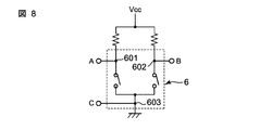
- FIG. 8 is a circuit diagram showing an equivalent circuit of the encoder mechanism 6.
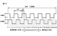
- FIG. 9 is a waveform diagram showing an output waveform of the encoder mechanism 6.
- a current flows between the points A and C, and the A signal is turned on.
- the second encoder terminal 602 and the third encoder terminal 603 are electrically connected, a current flows between point B and point C, and the B signal is turned on.
- the rotation angle of the slider 66 from the start of turning off the A signal to the start of the next off is 60 deg.
- the difference between the start of turning off the A signal and the start of turning off the B signal is 15 deg at the rotation angle of the slider 66.
- the change in the combination of ON and OFF of the A signal and the B signal is divided into 24. That is, it can be determined that the rotation angle of the slider 66 changes every 15 degrees in one rotation of the slider 66. Therefore, by determining changes in the A signal and the B signal, the rotation direction and rotation angle (rotation amount) of the slider 66 can be determined.
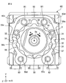
- FIG. 10 is a plan view of the encoder board 60, the shaft 3, and the restricting members (click springs 55, pendulums 56, 57).
- FIG. 11 is an exploded perspective view of the encoder board 60 and the restricting members (click spring 55, pendulum 56, 57).
- the regulating members (click spring 55, pendulum 56, 57) are arranged so as to surround the flange 30 of the shaft 3 when viewed from the direction of the axis 3a of the shaft 3.
- the pendulums 56 and 57 are made of, for example, a rigid body such as metal.
- the pendulums 56 and 57 are provided at annular base portions 56a and 57a provided with through holes 56d and 57d, arm portions 56b and 57b extending from the annular base portions 56a and 57a, and distal ends (free ends) of the arm portions 56b and 57b.
- Contact portions 56c and 57c With the two hinge pins 82 provided on the upper surface 60a of the encoder board 60 being inserted into the through holes 56d and 57d of the pendulums 56 and 57, each of the pendulums 56 and 57 is rotatably connected to the encoder board 60. ing.
- the contact portion 56c of the pendulum 56 also serves as the first locking portion
- the contact portion 57c of the pendulum 56 also serves as the second locking portion.
- each of the pendulums 56 and 57 is rotatably connected to the encoder board 60. May be.
- the click spring 55 is held on the upper surface 60a of the encoder board 60 so as to be movable as a whole within a predetermined range.
- the click spring 55 is provided at one end of the base portion 55a so as to be engaged with the U-shaped elastically deformable base portion 55a so as to surround the outer periphery of the flange portion 30 and the contact portion 56c side of the pendulum 56.
- the first locking portion 55b, a stopper portion 55c projecting outward from one end of the base portion 55a, and a second portion provided at the other end of the base portion 55a so as to be locked to the contact portion 57c side of the pendulum 57.
- Two locking portions 55d and a stopper portion 55e protruding outward from one end of the base portion 55a.
- contact portions 60 c and 60 d are provided at the corners of the encoder substrate 60.
- the stopper portion 55c of the click spring 55 is disposed at a distance from the contact portion 60c of the encoder substrate 60.
- the stopper portion 55e of the click spring 55 is disposed at a distance from the contact portion 60d of the encoder substrate 60.
- first locking portion 55 b and the second locking portion 55 d of the click spring 55 have arc-shaped convex surfaces 111 and 112 (curved surfaces) on the radially inner side of the shaft 3.
- the contact portions 56c and 57c of the pendulums 56 and 57 are formed on the outer side in the radial direction of the shaft 3 so as to face the first and second engaging portions 55b and 55d of the click spring 55. 122 (curved surface).
- the arc-shaped convex surface 111 of the first locking portion 55b of the click spring 55 and the arc-shaped concave surface 121 on the radially outer side of the contact portion 56c of the pendulum 56 are in contact with each other, so that the first spring The contact portion 56c of the pendulum 56 is locked to the locking portion 55b. Further, the arc-shaped convex surface 112 of the second locking portion 55d of the click spring 55 and the arc-shaped concave surface 122 on the radially outer side of the contact portion 57c of the pendulum 57 come into contact with each other, and the click spring 55 The contact portion 57c of the pendulum 57 is locked to the second locking portion 55d.
- the contact portions 56c and 57c of the pendulums 56 and 57 can contact the flange portion 30 (shown in FIG. 10) of the shaft 3, respectively.
- the contact portions 56 c and 57 c of the pendulums 56 and 57 are urged toward the shaft 3 side from the radially outer side of the shaft 3 by the click spring 55 and are urged to the convex portion 31 of the flange portion 30 of the shaft 3. While contacting, it fits in the recessed part 32 of the collar part 30 of the shaft 3, and the rotation angle of the shaft 3 is controlled.
- FIG. 12 is an explanatory diagram for explaining the operation of the flange portion 30 of the shaft 3, the click spring 55, and the pendulums 56 and 57.
- the contact portions 56c and 57c of the pendulums 56 and 57 are in contact with the apex of the convex portion 31 of the collar portion 30, as shown in FIG.
- the stopper portion 55c of the click spring 55 is in contact with or close to the contact portion 60c of the encoder substrate 60
- the stopper portion 55e of the click spring 55 is in contact with or close to the contact portion 60d of the encoder substrate 60.
- the contact portions 56c and 57c of the pendulums 56 and 57 get over the convex portion 31 of the collar portion 30 and fit into the concave portion 32 of the collar portion 30 again.
- the contact portion 56c of the pendulum 56 and the contact portion 57c of the pendulum 57 are simultaneously fitted in the recesses 32, 32 located on the opposite sides.
- the contact portion 56c of the pendulum 56 receives an outward force by the convex portion 31 of the flange portion 30, and the pendulum 56 rotates counterclockwise around the hinge pin 82.
- the contact portion 57c of the pendulum 57 receives an outward force by the convex portion 31 of the flange portion 30, and the pendulum 57 rotates clockwise about the hinge pin 82.
- Two pins 81 are provided on the upper surface 60a of the encoder board 60 and on the inner side in the radial direction of the shaft 3 of the click spring 55.
- the pins 81 and the contact portions 60c and 60d of the encoder board 60 regulate the movement of the click spring 55 in the Y direction and the X direction.
- the click spring 55 is held on the encoder board 60 so that the entire click spring 55 can move within a predetermined range.
- FIG. 13A the casing 2 is inverted and set so that the upper wall 21 is on the lower side.
- FIG. 13B the operating portion 35 of the shaft 3 is inserted into the hole 21 a of the upper wall 21, and the shaft 3 is installed in the casing 2.
- 21c is a convex part which protrudes in the negative direction of a Z direction by four recessed parts 21b (shown in FIG. 1) provided in the upper wall 21 of the casing 2.
- the four convex portions 21c abut on the region S1 including the stopper portion 55c of the click spring 55, the region S2 including the stopper portion 55e, the region S3 of the pendulum 56, and the region S4 of the pendulum 57, respectively. Thereby, the movement of the click spring 55 in the axial direction of the shaft 3 is restricted.
- the four convex portions 21c provided in the casing 2 are an example of a movement restricting member.
- an encoder board 60 provided with resistor patterns 61, 62, 63 and restricting members (click springs 55, pendulums 56, 57) is inserted into the end portion 36 of the shaft 3, and the casing 2 Install in.
- the protrusion 60 b of the encoder board 60 is fitted into the groove 22 b of the side wall 22 of the casing 2. Both sides in the Y direction of the encoder board 60 are sandwiched between the protruding wall 23 and the protruding piece 24 of the casing 2.
- the encoder terminals 601, 602, and 603 are not bent except for the end portions.
- the rotor 65 is inserted into the end portion 36 of the shaft 3 and installed in the casing 2.
- the short diameter portion 652 of the rotor 65 is passed through the locking portion 22 c of the side wall 22 of the casing 2, and the rotor 65 is assembled to the casing 2. Since the short diameter portion 652 is not locked to the locking portion 22c, the assembly of the rotor 65 to the casing 2 is facilitated.
- the operating portion 35 of the shaft 3 is operated to rotate the rotor 65, so that the long diameter portion 651 of the rotor 65 becomes the locking portion of the side wall 22 of the casing 2. 22c. Since the long diameter portion 651 is locked to the locking portion 22c by the rotation of the rotor 65, the assembled state of the rotor 65 to the casing 2 can be maintained.
- the casing 2 is inverted so that the upper wall 21 is on the upper side. At this time, since the rotor 65 is locked to the locking portion 22c of the side wall 22 of the casing 2, the rotor 65 does not fall downward.
- the conductor 71 is fitted into the recess 70a of the switch board 70 provided with the switch terminals 701, 702, 703, and the casing 2 is attached to the switch board 70 from the upper side of the switch board 70.
- the casing 2 can be attached to the switch board 70 while the conductor 71 remains fitted in the recess 70 a of the switch board 70.
- the protrusion 70 b of the switch board 70 is fitted into the hole 22 a of the side wall 22 of the casing 2, and the switch board 70 is fixed to the casing 2.
- the encoder board 60 is fixed to the hole 22a of the side wall 22 as the encoder fixing part of the casing 2
- the switch board 70 is formed of the groove part 22b of the side wall 22 as the switch fixing part of the casing 2, the protruding wall 23, and Since it is fixed to the projecting piece 24, the encoder board 60 and the switch board 70 can be integrated using the casing 2. Therefore, the bonding strength between the encoder board 60 and the switch board 70 can be improved without increasing the number of components.
- the portions of the encoder terminals 601, 602, 603 protruding from the encoder board 60 are bent, and the ends of the encoder terminals 601, 602, 603 are locked to the stepped portion 70c.
- the encoder board 60 and the switch board 70 are integrally held by the bent encoder terminals 601, 602, and 603. Accordingly, the encoder board 60 and the switch board 70 can be integrated using the encoder terminals 601, 602, and 603. Therefore, the bonding strength between the encoder board 60 and the switch board 70 can be improved without increasing the number of components.
- the rotary encoder 1 has a smooth torque fluctuation accompanying the counterclockwise rotation of the shaft 3 of the rotary encoder 1, and has a good click feeling. It was.
- the restricting members click springs 55, pendulums 56, 57
- the rotary encoder 1 can be reduced in size.
- the regulating member regulates the rotation angle of the shaft 3 by the flange portion 30 of the shaft 3
- the shaft 3 is attached to a part of the encoder mechanism 6 (for example, the rotor 65).
- the function of regulating the rotation angle is not provided. For this reason, it is not necessary to enlarge the encoder mechanism 6 (especially the rotor 65), and the rotary encoder 1 can be reduced in size.
- the click spring 55 and the pendulums 56 and 57 are plane-symmetric with respect to a plane passing through the axis 3a of the shaft 3 and along the Y direction.
- the behavior of the pendulums 56 and 57 is synchronized, so that the same is true regardless of whether the shaft 3 is rotated clockwise or counterclockwise. Click feeling can be obtained.
- each of the pendulums 56 and 57 is rotatably connected to the encoder board 60, and the other end of the pendulum 56 and 57 is a free end that contacts the convex portion 31 and the concave portion 32 of the shaft 3, and the pendulums 56 and 57 Since the click spring 55 is locked to the free end side, the free ends of the pendulums 56 and 57 are constrained to rotate on the arc, and the behavior of the pendulums 56 and 57 accompanying the rotation of the shaft 3 is stabilized. . Thereby, a smooth click feeling is obtained.
- the pendulums 56 and 57 need not be elastically deformed only by rotating with the rotation of the shaft 3, and can be formed of a rigid body such as metal. Therefore, the pendulums 56 and 57 and the shaft 3 can be made of metal to increase the strength, and the reliability can be improved.
- the pendulums 56 and 57 are attached to the shaft 3 by a click spring 55 having an elastically deformable base 55a and first and second engaging portions 55b and 55d that are engaged with the free ends of the pendulums 56 and 57. Since it is urged toward the shaft 3 side from the outside in the radial direction and comes into contact with the convex portion 31 and the concave portion 32 of the flange portion 30 from both sides of the shaft 3, a smooth click feeling is provided in any of the rotational directions of the shaft 3. It is obtained in the same way.
- the pendulums 56 and 57 are disposed in a plane symmetric position with respect to a plane passing through the axis of the shaft 3, and the convex portion 31 of the flange portion 30 of the shaft 3 is plane symmetric with respect to a plane passing through the axis of the shaft 3 And the concave portion 32 of the flange portion 30 of the shaft 3 is disposed in a plane-symmetrical position with respect to a plane passing through the axis of the shaft 3, so that the pendulums 56 and 57 have the flange portion of the shaft 3. Since the contact state with respect to the convex part 31 and the concave part 32 of the part 30 is synchronized, a smoother click feeling can be obtained.
- the click spring 55 is held on the encoder board 60 so that the entire click spring 55 can move within a predetermined range, the click spring 55 is elastically deformed so that the entire click spring 55 is bent as the shaft 3 rotates. As a result, stress concentration on the click spring 55 can be alleviated, and fatigue failure of the click spring 55 due to repeated elastic deformation can be prevented.
- the click spring 55 and the pendulums 56 and 57 of the regulating member are locked by curved surfaces (convex surfaces 111 and 112 and concave surfaces 121 and 122) that come into contact with each other.
- the contact area can be increased.
- the surface pressure decreases, so that wear on the contact surface between the contact member and the pendulums 56 and 57 can be reduced, and reliability can be improved.
- a restricting member (click spring 55, pendulum 56, 57) for restricting the rotation angle of the shaft 3, an encoder mechanism 6 for detecting the rotation direction and the rotation angle of the shaft 3, and a shaft by movement along the axis of the shaft 3 3 and a switch mechanism 7 that is pressed by 3.
- the click function of the restricting member click spring 55, pendulum 56, 57
- the encoder function of the encoder mechanism 6, and the switch function of the switch mechanism 7 can be controlled by one shaft 3.
- the three functions can be integrally controlled by the single shaft 3, and the size of the rotary encoder 1 can be reduced.
- the rotor 65 does not restrain the axial behavior of the shaft 3.
- the shaft 3 when the shaft 3 is pressed toward the switch mechanism 7 and when the shaft 3 is pushed back by the conductor 71 after the pressing, the shaft 3 slides on the hole 65a of the rotor 65 to move the rotor 65. Do not pull.
- the slider 66 is not deformed by being pressed by the resistor patterns 61, 62, and 63, and the slider 66 is separated from the resistor patterns 61, 62, and 63 to cause poor conduction. There is nothing to do.
- the regulating member (click spring 55, pendulum 56, 57) and the resistor patterns 61, 62, 63 are located on the opposite side with respect to the encoder board 60.
- the wear powder is applied to the encoder substrate 60. It is blocked and does not enter the resistor pattern 61, 62, 63 side. Accordingly, it is possible to prevent the electrical characteristics of the encoder mechanism 6 from being deteriorated by the wear powder.
- the rotary encoder has been described as an example of the rotary electronic component.
- the rotary electronic component of the present invention is not limited to the rotary encoder, and is applicable to other rotary electronic components such as a potentiometer and a trimmer capacitor. can do.
- the rotary encoder provided with the restricting member having the click spring 55 (biasing member) and the pendulums 56 and 57 (contact member) has been described.
- the restricting member includes the convex portion and the concave portion of the flange portion of the shaft.
- the present invention may be applied to a rotary electronic component including one contact member that contacts the shaft and one urging member that urges the contact member from the radially outer side of the shaft toward the shaft.
- the rotary encoder in which the click spring 55 (biasing member) and the free end sides of the pendulums 56 and 57 (contact member) are brought into contact with each other with curved surfaces and locked is described. You may make it latch on the free end side of a contact member in the state connected by the rotating shaft etc.
- the shaft 3 and the pendulums 56 and 57 are made of metal, and the click spring 55 (biasing member) is made of a resin having wear resistance. You may form with the resin which has abrasion property.
- the switch mechanism 7 is provided, but the switch mechanism may be omitted.
- the collar part is provided integrally with the shaft, the shaft may be separated from the shaft part and the collar part.
- the restriction member, the encoder mechanism, and the switch mechanism are arranged in order from the upper side to the lower side along the shaft axis.
- the restriction member, the encoder mechanism, and the switch mechanism are arranged along the shaft axis. The order may be changed.
Landscapes
- Rotary Switch, Piano Key Switch, And Lever Switch (AREA)
- Adjustable Resistors (AREA)
- Transmission And Conversion Of Sensor Element Output (AREA)
Abstract
回転式電子部品(1)は、ベース部材(60)と、軸(3a)を中心として回転可能となるようにベース部材(60)に取り付けられたシャフト(3)と、シャフト(3)の回転角度を規制する規制部材(55、56、57)とを備え、シャフト(3)は、周方向に交互に配列された複数の凸部(31)および凹部(32)を含む鍔部(30)を有し、規制部材(55、56、57)は、シャフト(3)の鍔部(30)の凸部(31)および凹部(32)に接触する接触部材(56、57)と、接触部材(56、57)をシャフト(3)の径方向外側からシャフト(3)側に向かって付勢する付勢部材(55)とを有する。
Description
本発明は、回転式電子部品に関する。
従来、回転式電子部品としては、特開2004-95242号公報(特許文献1)に記載されたものがある。この回転式電子部品は、シャフトと、シャフトの回転角度を規制する規制部材と、シャフトの回転方向および回転角度を検知するエンコーダ機構とを有する。
前記従来の回転式電子部品のエンコーダ機構は、シャフトに取り付けられたロータと、ロータに取り付けられた摺動子とを有する。また、規制部材は、ロータの外周面に接触してシャフトの回転角度を規制する。
ところで、前記従来の回転式電子部品では、規制部材は、ロータの外周面にボールを接触させて、シャフトの回転角度を規制している。具体的には、規制部材により押圧されたボールが、前記ロータの外周の凹部に入り込み、弾圧挟持される構造となっている。この構造で小型化を図る場合、各部品の高い加工精度、組立精度が必要であり、実現が難しい。また、信頼性を確保することも難しい。
そこで、本発明の課題は、小型化を図ることができる回転式電子部品を提供することにある。
前記課題を解決するため、本発明の回転式電子部品は、
ベース部材と、
軸を中心として回転可能となるように前記ベース部材に取り付けられたシャフトと、
前記シャフトの回転角度を規制する規制部材とを備え、
前記シャフトは、周方向に交互に配列された複数の凸部および凹部を含む鍔部を有し、
前記規制部材は、
前記シャフトの前記凸部および前記凹部に接触する接触部材と、
前記接触部材を前記シャフトの径方向外側から前記シャフト側に向かって付勢する付勢部材とを有する。
ベース部材と、
軸を中心として回転可能となるように前記ベース部材に取り付けられたシャフトと、
前記シャフトの回転角度を規制する規制部材とを備え、
前記シャフトは、周方向に交互に配列された複数の凸部および凹部を含む鍔部を有し、
前記規制部材は、
前記シャフトの前記凸部および前記凹部に接触する接触部材と、
前記接触部材を前記シャフトの径方向外側から前記シャフト側に向かって付勢する付勢部材とを有する。
本発明の回転式電子部品によれば、規制部材の接触部材は、付勢部材によりシャフトの径方向外側からシャフト側に向かって付勢されて、シャフトの鍔部の凸部に付勢して接触する一方、シャフトの鍔部の凹部に嵌まってシャフトの回転角度を規制する。このように、シャフトの回転角度を規制する規制部材を簡単な構成で小型化でき、この結果、回転式電子部品の小型化を図ることができる。
なお、前記シャフトの回転方向および回転角度を検知するエンコーダ機構を設けることによって、小型化された回転エンコーダを提供できる。
また、シャフトの軸に沿った移動によりシャフトに押圧されるスイッチ機構を設けるようにしてもよく、シャフトは、回転角度の規制動作と軸方向のスイッチ動作とを兼用できる。
また、回転式電子部品の一実施形態では、
前記接触部材は、一端が前記ベース部材に回動可能に連結され、他端が前記シャフトの前記凸部および前記凹部に接触する自由端であり、
前記付勢部材は、前記接触部材の自由端側に係止している。
前記接触部材は、一端が前記ベース部材に回動可能に連結され、他端が前記シャフトの前記凸部および前記凹部に接触する自由端であり、
前記付勢部材は、前記接触部材の自由端側に係止している。
前記実施形態によれば、接触部材の一端がベース部材に回動可能に連結され、接触部材の他端がシャフトの凸部および凹部に接触する自由端であり、その接触部材の自由端側に付勢部材が係止しているので、接触部材の自由端は円弧上を回動するように拘束され、シャフトの回転に伴う接触部材の挙動が安定する。これにより、滑らかなクリック感が得られる。
また、回転式電子部品の一実施形態では、
前記規制部材の前記接触部材は、前記シャフトの両側に配置された第1の接触部材と第2の接触部材とを有し、
前記規制部材の前記付勢部材は、
弾性変形可能な基部と、
前記第1の接触部材の自由端側に係止するように、前記基部の一端に設けられた第1の係止部と、
前記第2の接触部材の自由端側に係止するように、前記基部の他端に設けられた第2の係止部とを有する。
前記規制部材の前記接触部材は、前記シャフトの両側に配置された第1の接触部材と第2の接触部材とを有し、
前記規制部材の前記付勢部材は、
弾性変形可能な基部と、
前記第1の接触部材の自由端側に係止するように、前記基部の一端に設けられた第1の係止部と、
前記第2の接触部材の自由端側に係止するように、前記基部の他端に設けられた第2の係止部とを有する。
前記実施形態によれば、弾性変形可能な基部と第1,第2の接触部材の自由端側に係止する第1,第2の係止部とを有する付勢部材により、規制部材の第1,第2の接触部材は、シャフトの径方向外側からシャフト側に向かって付勢されて、シャフトの両側から鍔部の凸部と凹部に接触するので、シャフトの回転方向のいずれにおいても、滑らかなクリック感が同じように得られる。
また、回転式電子部品の一実施形態では、
前記規制部材の前記第1の接触部材と前記第2の接触部材は、前記シャフトの軸を通る平面に対して面対称な位置に配置されている。
前記規制部材の前記第1の接触部材と前記第2の接触部材は、前記シャフトの軸を通る平面に対して面対称な位置に配置されている。
前記実施形態によれば、規制部材の第1の接触部材と第2の接触部材が、シャフトの軸を通る平面に対して面対称な位置に配置されていることによって、第1の接触部材と第2の接触部材においてシャフトの鍔部の凸部と凹部に対する接触状態が同期するので、より滑らかなクリック感が得られる。
また、回転式電子部品の一実施形態では、
前記シャフトの前記鍔部の前記凸部は、前記シャフトの軸を通る平面に対して面対称な位置に配置されると共に、
前記シャフトの前記鍔部の前記凹部は、前記シャフトの軸を通る平面に対して面対称な位置に配置されている。
前記シャフトの前記鍔部の前記凸部は、前記シャフトの軸を通る平面に対して面対称な位置に配置されると共に、
前記シャフトの前記鍔部の前記凹部は、前記シャフトの軸を通る平面に対して面対称な位置に配置されている。
前記実施形態によれば、シャフトの鍔部の凸部は、シャフトの軸を通る平面に対して面対称な位置に配置されると共に、シャフトの鍔部の凹部は、シャフトの軸を通る平面に対して面対称な位置に配置されていることによって、第1の接触部材と第2の接触部材においてシャフトの鍔部の凸部と凹部に対する接触状態が同期するので、より滑らかなクリック感が得られる。
また、回転式電子部品の一実施形態では、
前記規制部材の前記付勢部材は、予め決められた範囲内で全体が移動可能なように前記ベース部材に保持されている。
前記規制部材の前記付勢部材は、予め決められた範囲内で全体が移動可能なように前記ベース部材に保持されている。
前記実施形態によれば、規制部材の付勢部材は、予め決められた範囲内で全体が移動可能なようにベース部材に保持されているので、シャフトの回転に伴って付勢部材全体がしなるように弾性変形することで、付勢部材に対する応力集中を緩和でき、弾性変形の繰り返しによる付勢部材の疲労破壊を防止できる。
また、回転式電子部品の一実施形態では、
前記規制部材の前記接触部材と前記付勢部材は、互いに接触する湾曲面によって係止している。
前記規制部材の前記接触部材と前記付勢部材は、互いに接触する湾曲面によって係止している。
前記実施形態によれば、規制部材の接触部材と付勢部材が、互いに接触する湾曲面によって係止していることによって、接触部材と付勢部材との接触面積を大きくすることができる。その結果、面圧が低下するので、接触部材と付勢部材との接触面の摩耗を低減でき、信頼性を向上できる。
また、回転式電子部品の一実施形態では、
前記規制部材の前記シャフトの軸方向の移動を規制する移動規制部材を備える。
前記規制部材の前記シャフトの軸方向の移動を規制する移動規制部材を備える。
前記実施形態によれば、移動規制部材によって規制部材のシャフトの軸方向の移動を規制するので、シャフトの回転に伴って規制部材がシャフトの軸方向に暴れることなく挙動が安定する。
本発明の回転式電子部品によれば、シャフトの回転角度を規制する規制部材を簡単な構成で小型化でき、この結果、回転式電子部品の小型化を図ることができる。
以下、本発明を図示の実施の形態により詳細に説明する。
図1は、本発明の一実施形態の回転式電子部品の一例としての回転エンコーダ1の上方からみた斜視図である。図2は、回転エンコーダ1の下方からみた斜視図である。図3は、回転エンコーダ1の上方からみた分解斜視図である。図4は、回転エンコーダ1の下方からみた分解斜視図である。図5は、回転エンコーダ1の断面図である。
各図において、回転エンコーダ1の幅方向をX方向とし、回転エンコーダ1の長さ方向をY方向とする。回転エンコーダ1の高さ方向をZ方向とする。Z方向の正方向を上側とし、Z方向の負方向を下側とする。
図1から図5に示すように、回転エンコーダ1は、ケーシング2と、軸を中心として回転可能となりかつ軸に沿って移動可能となるようにケーシング2に取り付けられたシャフト3と、シャフト3の回転角度を規制する規制部材(クリックバネ55,振り子56,57)と、シャフト3の回転方向および回転角度を検知するエンコーダ機構6と、シャフト3の軸に沿った移動によりシャフト3に押圧されるスイッチ機構7とを有する。規制部材(クリックバネ55,振り子56,57)とエンコーダ機構6とスイッチ機構7とは、シャフト3の軸に沿って、上側から下側に順に配置されている。クリックバネ55は接触部材の一例である。また、振り子56は第1の接触部材の一例であり、振り子57は第2の接触部材の一例である。
ケーシング2は、例えば、金属から構成される。ケーシング2は、シャフト3と規制部材(クリックバネ55,振り子56,57)とエンコーダ機構6とスイッチ機構7とを一体に組み付ける。
ケーシング2は、上壁21と、上壁21のX方向の両側に設けられ下方に延在する側壁22,22と、上壁21のY方向の正方向に設けられ下方に延在する突壁23と、上壁21のY方向の負方向に設けられ下方に延在する突片24とを有する。上壁21は、1つの孔部21aとその孔部21aの回りに4つの凹部21bを有する。側壁22は、下側に孔部22aと上側に溝部22bとを有する。孔部22aの内面には、ケーシング2の内側に突出する係止部22cが設けられている。突壁23は、上壁21のX方向の全長にわたって延在している。突片24は、上壁21のX方向の中央部に設けられている。
シャフト3は、例えば、樹脂から構成される。シャフト3は、操作部35と歯車状の鍔部30と端部36とを有する。操作部35と歯車状の鍔部30と端部36とは、軸に沿って、上側から下側に順に配置されている。操作部35は、シャフト3の回転の目印となる切欠を有する。歯車状の鍔部30は、複数の凸部31および凹部32を含む。複数の凸部31および凹部32は、周方向に交互に配列されている。操作部35は、ケーシング2の上壁21の孔部21aを貫通しており、使用者は、ケーシング2の外側から操作部35を操作することができる。
エンコーダ機構6は、ベース部材の一例としてのエンコーダ基板60と、エンコーダ基板60に設けられた抵抗体パターン61,62,63と、エンコーダ基板60に設けられ、抵抗体パターン61,62,63に電気的に接続されるエンコーダ端子601,602,603と、シャフト3とともに回転可能となるようにシャフト3に取り付けられたロータ65と、ロータ65に取り付けられ抵抗体パターン61,62,63と摺接する摺動子66とを有する。
エンコーダ基板60は、例えば、樹脂から構成される。エンコーダ基板60の上面60aに、規制部材(クリックバネ55,振り子56,57)が取り付けられている。エンコーダ基板60のX方向の両側には、突部60bが設けられている。突部60bは、ケーシング2の側壁22の溝部22bに嵌め込まれている。エンコーダ基板60のY方向の両側は、突壁23と突片24によって挟まれている。このように、エンコーダ基板60は、側壁22の溝部22bと突壁23と突片24とによって、ケーシング2に固定されている。言い換えると、側壁22の溝部22bと突壁23と突片24とは、エンコーダ基板60を固定するエンコーダ固定部を構成する。
抵抗体パターン61,62,63は、エンコーダ基板60の下面に設けられている。抵抗体パターン61,62,63は、シャフト3の回転方向および回転角度を検知するためのものである。第1抵抗体パターン61と第2抵抗体パターン62と第3抵抗体パターン63とは、環状に形成され、同心状に配置されている。第1抵抗体パターン61と第2抵抗体パターン62と第3抵抗体パターン63とは、径方向の外側から内側に順に配置されている。第1抵抗体パターン61と第2抵抗体パターン62とは、それぞれ、間欠的に形成されている。第3抵抗体パターン63は、連続的に形成されている。
エンコーダ端子601,602,603は、エンコーダ基板60にインサート成形されている。第1エンコーダ端子601は、第1抵抗体パターン61に電気的に接続され、第2エンコーダ端子602は、第2抵抗体パターン62に電気的に接続され、第3エンコーダ端子603は、第3抵抗体パターン63に電気的に接続されている。
ロータ65は、シャフト3に対して、周方向に位置決めされ、かつ、軸方向に移動可能となる。具体的に述べると、ロータ65は、D形状の孔部65aを有する。シャフト3の端部36の外周面は、D形状に形成されている。D形状の端部36が、D形状の孔部65aに嵌合されて、ロータ65は、シャフト3に対して周方向に固定され軸方向に固定されない。
ロータ65は、略長円形状に形成されている。ロータ65は、ロータ65の外径が長径となる長径部651と、ロータ65の外径が短径となる短径部652とを有する。長径部651の長さは、対向する側壁22の係止部22cの間の隙間よりも大きく、短径部652の長さは、対向する側壁22の係止部22cの間の隙間よりも小さい。言い換えると、係止部22cは、短径部652が係止しないで離脱され、かつ、長径部651がロータ65の回転により係脱可能となるように、構成されている。
摺動子66は、例えば、金属から構成される。摺動子66は、ロータ65の上面の2つの突部65bに固定される。摺動子66は、環状に形成される。摺動子66は、第1接点部661と第2接点部662と第3接点部663とを有する。第1接点部661と第2接点部662と第3接点部663とは、径方向の外側から内側に順に配置されている。第1接点部661と第2接点部662と第3接点部663とは、導通している。第1接点部661は、第1抵抗体パターン61に接触可能となり、第2接点部662は、第2抵抗体パターン62に接触可能となり、第3接点部663は、第3抵抗体パターン63に接触可能となる。
スイッチ機構7は、スイッチ基板70と、スイッチ基板70に設けられた第1から第3スイッチ端子701,702,703と、スイッチ基板70に設けられ、シャフト3の端部36に押圧される導電体71とを有する。導電体71は、第1、第2スイッチ端子701,702に電気的に接続される。導電体71は、シャフト3の端部36に押圧されて、第3スイッチ端子703に電気的に接続され、第1、第2スイッチ端子701,702と第3スイッチ端子703とを導通する。第1、第2スイッチ端子701,702と第3スイッチ端子703とが導通すると、スイッチ信号がオンとなる。例えば、スイッチ信号のオンにより、各機能が動作する。なお、第1、第2スイッチ端子701,702のうちの一方のスイッチ端子のみ設けてもよい。
スイッチ基板70のX方向の両側には、突部70bが設けられている。突部70bは、ケーシング2の側壁22の孔部22aに嵌め込まれている。このように、スイッチ基板70は、側壁22の孔部22aによって、ケーシング2に固定されている。言い換えると、側壁22の孔部22aは、スイッチ基板70を固定するスイッチ固定部を構成する。
スイッチ基板70の下面のX方向の一辺には、段部70cが設けられている。段部70cには、折り曲げられたエンコーダ端子601,602,603の端部が、係止している。つまり、エンコーダ基板60とスイッチ基板70とは、折り曲げられたエンコーダ端子601,602,603によって、一体に抱えられている。
段部70cの深さは、エンコーダ端子601,602,603の厚みよりも深い。これにより、スイッチ基板70の下面を実装基板に設置したとき、エンコーダ端子601,602,603でなく、スイッチ基板70の下面を設置面とできる。
第1から第3スイッチ端子701,702,703は、スイッチ基板70にインサート成形されている。第3スイッチ端子703は、第1スイッチ端子701と第2スイッチ端子702との間に、位置する。
導電体71は、弾性を有する。導電体71は、ドーム状に形成されている。導電体71は、スイッチ基板70の上面の凹部70aに嵌め込まれている。
導電体71の周縁部分71aは、第1、第2スイッチ端子701,702に電気的に接続されている。導電体71の天頂部分71bは、導電体71の自由状態で、第3スイッチ端子703から離隔する一方、シャフト3の端部36に押圧されて第3スイッチ端子703に電気的に接続される。
つまり、シャフト3を下側に押圧すると、シャフト3の端部36が、導電体71の天頂部分71bを押圧して、導電体71の天頂部分71bが、第3スイッチ端子703に電気的に接続される。これにより、第1、第2スイッチ端子701,702と第3スイッチ端子703とが、電気的に接続されて、スイッチ信号がオンとなる。
一方、シャフト3の下側への押圧を解除すると、導電体71が自由状態に戻ることで、シャフト3が上側に移動し、導電体71の天頂部分71bが、第3スイッチ端子703から離隔する。これにより、第1、第2スイッチ端子701,702と第3スイッチ端子703とが、電気的に接続されず、スイッチ信号がオフとなる。
図6は、エンコーダ機構6の下方からみた分解斜視図である。図6に示すように、エンコーダ基板60の下面には、第1、第2、第3電極部671,672,673が設けられている。第1電極部671と第2電極部672と第3電極部673とは、環状に形成され、同心状に配置されている。第1電極部671と第2電極部672と第3電極部673とは、径方向の外側から内側に順に配置されている。第1電極部671は、第1エンコーダ端子601の端部601aに電気的に接続され、第2電極部672は、第2エンコーダ端子602の端部602aに電気的に接続され、第3電極部673は、第3エンコーダ端子603の端部603aに電気的に接続されている。
第1、第2、第3電極部671,672,673上には、絶縁シート68が積層されている。絶縁シート68は、第1電極部671が周方向に間欠的に露出し、かつ、第2電極部672が周方向に間欠的に露出するように、第1電極部671および第2電極部672を覆う。つまり、絶縁シート68は、周方向に間欠的に配置される複数の孔部68aを有し、第1電極部671および第2電極部672が、絶縁シート68の孔部68aから、露出する。第3電極部673は、絶縁シート68に覆われていない。
第1電極部671が絶縁シート68から露出している部分に第1抵抗体パターン61を設け、第2電極部672が絶縁シート68から露出している部分に第2抵抗体パターン62を設け、第3電極部673に第3抵抗体パターン63を設けている。
これにより、第1抵抗体パターン61は、第1電極部671を介して、第1エンコーダ端子601に電気的に接続され、第2抵抗体パターン62は、第2電極部672を介して、第2エンコーダ端子602に電気的に接続され、第3抵抗体パターン63は、第3電極部673を介して、第3エンコーダ端子603に電気的に接続される。
図7は、エンコーダ機構6の下方からみた斜視図である。図7に示すように、摺動子66の第1接点部661は、第1抵抗体パターン61に対応した位置にあり、摺動子66の第2接点部662は、第2抵抗体パターン62に対応した位置にあり、摺動子66の第3接点部663は、第3抵抗体パターン63に対応した位置にある。
そして、摺動子66の回転により、第1接点部661は、第1抵抗体パターン61と絶縁シート68とに交互に接触し、第2接点部662は、第2抵抗体パターン62と絶縁シート68とに交互に接触する。第3接点部663は、常時、第3抵抗体パターン63に接触している。つまり、摺動子66の回転により、第1エンコーダ端子601と第3エンコーダ端子603とが、間欠的に電気的に接続され、第2エンコーダ端子602と第3エンコーダ端子603とが、間欠的に電気的に接続される。
図8は、エンコーダ機構6の等価回路を示す回路図である。図9は、エンコーダ機構6の出力波形を示す波形図である。図8と図9に示すように、第1エンコーダ端子601と第3エンコーダ端子603とが、電気的に接続されると、A点とC点の間に電流が流れて、A信号がオンとなる。第2エンコーダ端子602と第3エンコーダ端子603とが、電気的に接続されると、B点とC点の間に電流が流れて、B信号がオンとなる。
摺動子66の時計回り方向の回転において、A信号のオフの始まりから次のオフの始まりまでの摺動子66の回転角度は、60degとなる。B信号についても同様である。また、A信号のオフの始まりとB信号のオフの始まりのずれは、摺動子66の回転角度において、15degとなる。そして、摺動子66の1回転(つまり、摺動子66の回転角度は、360degである)において、A信号およびB信号のオンとオフの組み合わせの変化は、24に分けられる。つまり、摺動子66の1回転において、摺動子66の回転角度が15degごとに変化することを判断できる。したがって、A信号とB信号の変化を判断することで、摺動子66の回転方向と回転角度(回転量)を判断できる。
図10は、エンコーダ基板60、シャフト3および規制部材(クリックバネ55,振り子56,57)の平面図である。図11は、エンコーダ基板60と規制部材(クリックバネ55,振り子56,57)の分解斜視図である。
図10と図11に示すように、規制部材(クリックバネ55,振り子56,57)は、シャフト3の軸3a方向からみて、シャフト3の鍔部30を囲むように配置されている。
振り子56,57は、例えば、金属などの剛体から構成される。この振り子56,57は、貫通穴56d,57dが設けられた環状基部56a,57aと、環状基部56a,57aから延びるアーム部56b,57bと、アーム部56b,57bの先端(自由端)に設けられた接点部56c,57cを有する。振り子56,57の貫通穴56d,57dに、エンコーダ基板60の上面60aに設けられた2つのヒンジピン82が挿入された状態で、振り子56,57の夫々がエンコーダ基板60に回動可能に連結されている。振り子56の接点部56cは、第1の係止部を兼ねると共に、振り子56の接点部57cは、第2の係止部を兼ねる。
なお、振り子56,57側にピンを設け、エンコーダ基板60に設けられた穴に振り子56,57のピンを挿入することによって、振り子56,57の夫々をエンコーダ基板60に回動可能に連結してもよい。
また、クリックバネ55は、予め決められた範囲内で全体が移動可能なようにエンコーダ基板60の上面60aに保持されている。また、クリックバネ55は、鍔部30の外周を囲むようにU字型をした弾性変形可能な基部55aと、振り子56の接点部56c側に係止するように、基部55aの一端に設けられた第1の係止部55bと、基部55aの一端に外側に突設されたストッパー部55cと、振り子57の接点部57c側に係止するように、基部55aの他端に設けられた第2の係止部55dと、基部55aの一端に外側に突設されたストッパー部55eを有する。
なお、エンコーダ基板60のコーナー部に当接部60c,60dを設けている。クリックバネ55のストッパー部55cは、エンコーダ基板60の当接部60cと間隔をあけて配置されている。また、クリックバネ55のストッパー部55eは、エンコーダ基板60の当接部60dと間隔をあけて配置されている。
また、クリックバネ55の第1の係止部55b,第2の係止部55dは、シャフト3の径方向内側に円弧形状の凸面111,112(湾曲面)を有している。一方、振り子56,57の接点部56c,57cは、シャフト3の径方向外側に、クリックバネ55の第1の係止部55b,第2の係止部55dに対向する円弧形状の凹面121,122(湾曲面)を有している。
クリックバネ55の第1の係止部55bの円弧形状の凸面111と、振り子56の接点部56cの径方向外側の円弧形状の凹面121とが、互いに接触して、クリックバネ55の第1の係止部55bに振り子56の接点部56cが係止する。また、クリックバネ55の第2の係止部55dの円弧形状の凸面112と、振り子57の接点部57cの径方向外側の円弧形状の凹面122とが、互いに接触して、クリックバネ55の第2の係止部55dに振り子57の接点部57cが係止する。
振り子56,57の接点部56c,57cは、それぞれ、シャフト3の鍔部30(図10に示す)に接触可能となる。この振り子56,57の接点部56c,57cは、クリックバネ55によりシャフト3の径方向外側からシャフト3側に向かって付勢されて、シャフト3の鍔部30の凸部31に付勢して接触する一方、シャフト3の鍔部30の凹部32に嵌まってシャフト3の回転角度を規制する。
図12は、シャフト3の鍔部30とクリックバネ55および振り子56,57の動作を説明する説明図である。
振り子56,57の接点部56c,57cが鍔部30の凹部32に嵌まった図10に示す状態から、シャフト3を軸3aを中心として回転させると、クリックバネ55が弾性変形しながら、振り子56,57の接点部56c,57cをシャフト3の径方向外側からシャフト3側に向かって付勢しつつ、鍔部30の凸部31により外向きに力を受けた振り子56,57がヒンジピン82を中心に外側に回動する。そうして、振り子56,57の接点部56c,57cは、図12に示すように、鍔部30の凸部31の頂点と接する。ここで、クリックバネ55のストッパー部55cは、エンコーダ基板60の当接部60cに接するかまたは近接すると共に、クリックバネ55のストッパー部55eは、エンコーダ基板60の当接部60dに接するかまたは近接する。
その後、振り子56,57の接点部56c,57cは、鍔部30の凸部31を乗り越えて、再び鍔部30の凹部32に嵌まる。このとき、振り子56の接点部56cと振り子57の接点部57cとは、互いに反対側に位置する凹部32,32に、同時に嵌まる。
シャフト3を時計回り方向Aに回転するとき、振り子56の接点部56cは、鍔部30の凸部31により外向きに力を受けて、振り子56がヒンジピン82を中心に反時計回りに回動する。一方、シャフト3を時計回り方向Aに回転するとき、振り子57の接点部57cは、鍔部30の凸部31により外向きに力を受けて、振り子57がヒンジピン82を中心に時計回りに回動する。
同様に、シャフト3を反時計回り方向Bに回転すると、振り子56の接点部56cは、鍔部30の凸部31により外向きに力を受けて、振り子56がヒンジピン82を中心に反時計回りに回動する。一方、シャフト3を時計回り方向Bに回転すると、振り子57の接点部57cは、鍔部30の凸部31により外向きに力を受けて、振り子57がヒンジピン82を中心に時計回りに回動する。
エンコーダ基板60の上面60aかつクリックバネ55のシャフト3の径方向の内側に、2つのピン81を設けている。このピン81とエンコーダ基板60の当接部60c,60dによって、クリックバネ55のY方向とX方向の移動を規制する。このように、クリックバネ55は、予め決められた範囲内で全体が移動可能なようにエンコーダ基板60に保持されている。
次に、回転エンコーダ1の組立方法を説明する。
図13Aに示すように、ケーシング2を、上壁21が下側になるように、反転してセットする。図13Bに示すように、上壁21の孔部21aに、シャフト3の操作部35を差し込んで、シャフト3をケーシング2に設置する。図13Aと図13Bにおいて、21cは、ケーシング2の上壁21に設けられた4つの凹部21b(図1に示す)によって、Z方向の負方向に突出する凸部である。
ここで、4つの凸部21cは、図10において、クリックバネ55のストッパー部55cを含む領域S1、ストッパー部55eを含む領域S2、振り子56の領域S3、振り子57の領域S4に夫々当接する。これにより、クリックバネ55のシャフト3の軸方向の移動を規制する。ケーシング2に設けられた4つの凸部21cは、移動規制部材の一例である。
なお、クリックバネ55のZ方向の厚さを調整することによって、回転トルクを調整して、クリック感を用途に応じて調整することが可能になる。この場合、クリックバネ55のZ方向の厚さに応じて、4つの凸部21cのZ方向の負方向の高さを適宜変更することによって、クリックバネ55のシャフト3の軸方向の移動を容易に規制することができる。
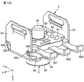
図13Cに示すように、抵抗体パターン61,62,63および規制部材(クリックバネ55,振り子56,57)が設けられたエンコーダ基板60を、シャフト3の端部36に挿入して、ケーシング2に設置する。このとき、エンコーダ基板60の突部60bは、ケーシング2の側壁22の溝部22bに嵌め込まれている。エンコーダ基板60のY方向の両側は、ケーシング2の突壁23および突片24に挟まれている。エンコーダ端子601,602,603は、端部を除いて折り曲げられていない。
図13Dに示すように、ロータ65を、シャフト3の端部36に挿入して、ケーシング2に設置する。このとき、ロータ65の短径部652を、ケーシング2の側壁22の係止部22cに通過させて、ロータ65をケーシング2に組み付ける。短径部652は、係止部22cに係止されないので、ロータ65のケーシング2への組み付けが容易となる。
図13Eに示すように、ロータ65をケーシング2に組み付けた後、シャフト3の操作部35を操作しロータ65を回転して、ロータ65の長径部651を、ケーシング2の側壁22の係止部22cに係止させる。長径部651は、ロータ65の回転により、係止部22cに係止されるので、ロータ65のケーシング2への組み付け状態を維持できる。
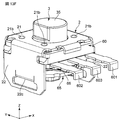
図13Fに示すように、ケーシング2を、上壁21が上側になるように、反転する。このとき、ロータ65は、ケーシング2の側壁22の係止部22cに係止されているので、ロータ65は、下側に落下しない。
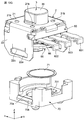
図13Gに示すように、スイッチ端子701,702,703が設けられたスイッチ基板70の凹部70aに導電体71を嵌め込み、スイッチ基板70の上側からケーシング2をスイッチ基板70に取り付ける。こうすることで、導電体71がスイッチ基板70の凹部70aに嵌まったままで、ケーシング2をスイッチ基板70に取り付けることができる。
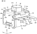
図13Hに示すように、スイッチ基板70の突部70bは、ケーシング2の側壁22の孔部22aに嵌め込まれて、スイッチ基板70は、ケーシング2に固定される。このように、エンコーダ基板60は、ケーシング2のエンコーダ固定部としての側壁22の孔部22aに固定され、スイッチ基板70は、ケーシング2のスイッチ固定部としての側壁22の溝部22b、突壁23および突片24に固定されるので、ケーシング2を利用して、エンコーダ基板60とスイッチ基板70とを一体化できる。したがって、部品数を増加することなく、エンコーダ基板60とスイッチ基板70との接合強度を向上できる。
図13Iに示すように、エンコーダ端子601,602,603のエンコーダ基板60から突出している部分を折り曲げて、エンコーダ端子601,602,603の端部を段部70cに係止する。こうすることで、エンコーダ基板60とスイッチ基板70とは、折り曲げられたエンコーダ端子601,602,603によって、一体に抱えられる。これにより、エンコーダ端子601,602,603を利用して、エンコーダ基板60とスイッチ基板70とを一体化できる。したがって、部品数を増加することなく、エンコーダ基板60とスイッチ基板70との接合強度を向上できる。
この実施形態の回転エンコーダ1は、シャフト3の回転角度に対するトルク変動を実験により測定した結果、シャフト3の時計方向の回転に伴うトルク変動が滑らかになり、良好なクリック感が得られた。
同様に、シャフト3の回転角度に対するトルク変動を実験により測定した結果、回転エンコーダ1は、回転エンコーダ1のシャフト3の反時計方向の回転に伴うトルク変動が滑らかになり、良好なクリック感が得られた。
このように、回転エンコーダ1は、振り子56,57の挙動が同期するため、シャフト3を時計回り、または、反時計回りのどちらに回転させても同様のクリック感覚が得られる。
この実施形態の回転エンコーダ1によれば、シャフト3の回転角度を規制する規制部材(クリックバネ55,振り子56,57)を簡単な構成で小型化でき、この結果、回転エンコーダ1の小型化を図ることができる。また、規制部材(クリックバネ55,振り子56,57)は、シャフト3の鍔部30により、シャフト3の回転角度を規制しているので、エンコーダ機構6の一部(例えばロータ65)にシャフト3の回転角度を規制する機能をもたせることがない。このため、エンコーダ機構6(特にロータ65)を大型にする必要がなく、回転エンコーダ1の小型化を図ることができる。
また、図10に示す状態で、クリックバネ55および振り子56,57は、シャフト3の軸3aを通りかつY方向に沿った平面に対して面対称となっている。これにより、シャフト3の回転方向を時計回りから反時計回りに変えた場合、振り子56,57の挙動が同期するため、シャフト3を時計回り、または、反時計回りのどちらに回転させても同様のクリック感覚が得られる。
また、振り子56,57の一端がエンコーダ基板60に回動可能に連結され、振り子56,57の他端がシャフト3の凸部31および凹部32に接触する自由端であり、その振り子56,57の自由端側にクリックバネ55が係止しているので、振り子56,57の自由端は円弧上を回動するように拘束され、シャフト3の回転に伴う振り子56,57の挙動が安定する。これにより、滑らかなクリック感が得られる。
このように、振り子56,57は、シャフト3の回転に伴って回動するだけで、弾性変形する必要がなく、金属などの剛体により形成することができる。したがって、振り子56,57とシャフト3を金属で形成して強度を高めることが可能なり、信頼性が向上できる。
また、弾性変形可能な基部55aと振り子56,57の自由端側に係止する第1,第2の係止部55b,55dとを有するクリックバネ55により、振り子56,57は、シャフト3の径方向外側からシャフト3側に向かって付勢されて、シャフト3の両側から鍔部30の凸部31と凹部32に接触するので、シャフト3の回転方向のいずれにおいても、滑らかなクリック感が同じように得られる。
また、振り子56,57が、シャフト3の軸を通る平面に対して面対称な位置に配置され、シャフト3の鍔部30の凸部31は、シャフト3の軸を通る平面に対して面対称な位置に配置されると共に、シャフト3の鍔部30の凹部32は、シャフト3の軸を通る平面に対して面対称な位置に配置されていることによって、振り子56,57においてシャフト3の鍔部30の凸部31と凹部32に対する接触状態が同期するので、より滑らかなクリック感が得られる。
また、クリックバネ55は、予め決められた範囲内で全体が移動可能なようにエンコーダ基板60に保持されているので、シャフト3の回転に伴ってクリックバネ55全体がしなるように弾性変形することで、クリックバネ55に対する応力集中を緩和でき、弾性変形の繰り返しによるクリックバネ55の疲労破壊を防止できる。
また、規制部材のクリックバネ55と振り子56,57が、互いに接触する湾曲面(凸面111,112および凹面121,122)によって係止していることによって、クリックバネ55と振り子56,57との接触面積を大きくすることができる。その結果、面圧が低下するので、接触部材と振り子56,57との接触面の摩耗を低減でき、信頼性を向上できる。
また、ケーシング2の上壁21に設けられた4つの凸部21c(移動規制部材)によって規制部材(クリックバネ55,振り子56,57)のシャフト3の軸方向の移動を規制するので、シャフト3の回転に伴って規制部材(クリックバネ55,振り子56,57)がシャフト3の軸方向に暴れることなく挙動が安定する。
また、シャフト3の回転角度を規制する規制部材(クリックバネ55,振り子56,57)と、シャフト3の回転方向および回転角度を検知するエンコーダ機構6と、シャフト3の軸に沿った移動によりシャフト3に押圧されるスイッチ機構7とを有する。これにより、1つのシャフト3によって、規制部材(クリックバネ55,振り子56,57)のクリック機能と、エンコーダ機構6のエンコーダ機能と、スイッチ機構7のスイッチ機能とを制御することができる。したがって、3つの機能を1つのシャフト3で一体に制御でき、回転エンコーダ1の小型化を実現できる。
また、ロータ65は、シャフト3の軸方向の挙動を拘束しない。これにより、シャフト3をスイッチ機構7側に押圧するとき、および、この押圧後にシャフト3が導電体71により押し戻されるとき、シャフト3は、ロータ65の孔部65aを摺動して、ロータ65を引っ張らない。このため、摺動子66は、抵抗体パターン61,62,63に押圧されて変形することがなく、また、摺動子66は、抵抗体パターン61,62,63から離れて導通不良が発生することがない。
また、規制部材(クリックバネ55,振り子56,57)と抵抗体パターン61,62,63とは、エンコーダ基板60に関して、反対側に位置している。これにより、規制部材(クリックバネ55,振り子56,57)とシャフト3の鍔部30との接触により、シャフト3の鍔部30から摩耗粉が発生しても、摩耗粉は、エンコーダ基板60に阻止されて、抵抗体パターン61,62,63側に侵入しない。したがって、摩耗粉によるエンコーダ機構6の電気特性の悪化を防止することができる。
なお、本発明は上述の実施形態に限定されず、本発明の要旨を逸脱しない範囲で設計変更可能である。
前記実施形態では、回転式電子部品の一例として回転エンコーダについて説明したが、この発明の回転式電子部品は、回転エンコーダに限らず、ポテンションメータやトリマコンデンサなどの他の回転式電子部品に適用することができる。
前記実施形態では、クリックバネ55(付勢部材)と振り子56,57(接触部材)とを有する規制部材を備えた回転エンコーダについて説明したが、規制部材は、シャフトの鍔部の凸部および凹部に接触する1つの接触部材と、接触部材をシャフトの径方向外側からシャフト側に向かって付勢する1つの付勢部材で構成された回転式電子部品にこの発明を適用してもよい。
前記実施形態では、クリックバネ55(付勢部材)と振り子56,57(接触部材)の自由端側とが互いに湾曲面で接触して係止する回転エンコーダについて説明したが、付勢部材は、回転軸などにより連結された状態で接触部材の自由端側に係止するようにしてもよい。
前記実施形態では、シャフト3と振り子56,57(接触部材)を金属で形成し、クリックバネ55(付勢部材)を耐摩耗性を有する樹脂により形成したが、シャフトや接触部材を剛性と耐摩耗性を有する樹脂により形成してもよい。
前記実施形態では、スイッチ機構7を設けているが、スイッチ機構を省略してもよい。また、鍔部は、シャフトに一体に設けているが、シャフトを、軸部と鍔部と別体にしてもよい。
前記実施形態では、規制部材とエンコーダ機構とスイッチ機構とは、シャフトの軸に沿って、上側から下側に順に配置されているが、規制部材、エンコーダ機構およびスイッチ機構のシャフトの軸に沿った順番を変更してもよい。
1 回転エンコーダ
2 ケーシング
21 上壁
21c 凸部(移動規制部材)
22 側壁
23 突壁
3 シャフト
3a 軸
30 鍔部
31 凸部
32 凹部
55 クリックバネ(付勢部材)
基部 55a
55b 第1の係止部
55e ストッパー部
55d 第2の係止部
55e ストッパー部
56,57 振り子(接触部材)
56a,57a 環状基部
56b,57b アーム部
56c,57c 接点部
56d,57d 貫通穴
6 エンコーダ機構
60 エンコーダ基板(ベース部材)
61,62,63 抵抗体パターン
601,602,603 エンコーダ端子
65 ロータ
66 摺動子
7 スイッチ機構
70 スイッチ基板
71 導電体
701,702,703 スイッチ端子
81 ピン
82 ヒンジピン
2 ケーシング
21 上壁
21c 凸部(移動規制部材)
22 側壁
23 突壁
3 シャフト
3a 軸
30 鍔部
31 凸部
32 凹部
55 クリックバネ(付勢部材)
基部 55a
55b 第1の係止部
55e ストッパー部
55d 第2の係止部
55e ストッパー部
56,57 振り子(接触部材)
56a,57a 環状基部
56b,57b アーム部
56c,57c 接点部
56d,57d 貫通穴
6 エンコーダ機構
60 エンコーダ基板(ベース部材)
61,62,63 抵抗体パターン
601,602,603 エンコーダ端子
65 ロータ
66 摺動子
7 スイッチ機構
70 スイッチ基板
71 導電体
701,702,703 スイッチ端子
81 ピン
82 ヒンジピン
Claims (8)
- ベース部材と、
軸を中心として回転可能となるように前記ベース部材に取り付けられたシャフトと、
前記シャフトの回転角度を規制する規制部材とを備え、
前記シャフトは、周方向に交互に配列された複数の凸部および凹部を含む鍔部を有し、
前記規制部材は、
前記シャフトの前記鍔部の前記凸部および前記凹部に接触する接触部材と、
前記接触部材を前記シャフトの径方向外側から前記シャフト側に向かって付勢する付勢部材とを有する、回転式電子部品。 - 前記接触部材は、一端が前記ベース部材に回動可能に連結され、他端が前記シャフトの前記凸部および前記凹部に接触する自由端であり、
前記付勢部材は、前記接触部材の自由端側に係止している、請求項1に記載の回転式電子部品。 - 前記規制部材の前記接触部材は、前記シャフトの両側に配置された第1の接触部材と第2の接触部材とを有し、
前記規制部材の前記付勢部材は、
弾性変形可能な基部と、
前記第1の接触部材の自由端側に係止するように、前記基部の一端に設けられた第1の係止部と、
前記第2の接触部材の自由端側に係止するように、前記基部の他端に設けられた第2の係止部とを有する、請求項2に記載の回転式電子部品。 - 前記規制部材の前記第1の接触部材と前記第2の接触部材は、前記シャフトの軸を通る平面に対して面対称な位置に配置されている、請求項3に記載の回転式電子部品。
- 前記シャフトの前記鍔部の前記凸部は、前記シャフトの軸を通る平面に対して面対称な位置に配置されると共に、
前記シャフトの前記鍔部の前記凹部は、前記シャフトの軸を通る平面に対して面対称な位置に配置されている、請求項4に記載の回転式電子部品。 - 前記規制部材の前記付勢部材は、予め決められた範囲内で全体が移動可能なように前記ベース部材に保持されている、請求項3から5の何れか一つに記載の回転式電子部品。
- 前記規制部材の前記接触部材と前記付勢部材は、互いに接触する湾曲面によって係止している、請求項1から6の何れか一つに記載の回転式電子部品。
- 前記規制部材の前記シャフトの軸方向の移動を規制する移動規制部材を備える、請求項1から7の何れか一つに記載の回転式電子部品。
Priority Applications (3)
| Application Number | Priority Date | Filing Date | Title |
|---|---|---|---|
| CN201780020523.4A CN108885956B (zh) | 2016-03-30 | 2017-03-09 | 旋转式电子部件 |
| JP2018508913A JP6485592B2 (ja) | 2016-03-30 | 2017-03-09 | 回転式電子部品 |
| US16/143,529 US10707035B2 (en) | 2016-03-30 | 2018-09-27 | Rotary electronic component |
Applications Claiming Priority (2)
| Application Number | Priority Date | Filing Date | Title |
|---|---|---|---|
| JP2016-069272 | 2016-03-30 | ||
| JP2016069272 | 2016-03-30 |
Related Child Applications (1)
| Application Number | Title | Priority Date | Filing Date |
|---|---|---|---|
| US16/143,529 Continuation US10707035B2 (en) | 2016-03-30 | 2018-09-27 | Rotary electronic component |
Publications (1)
| Publication Number | Publication Date |
|---|---|
| WO2017169625A1 true WO2017169625A1 (ja) | 2017-10-05 |
Family
ID=59964163
Family Applications (1)
| Application Number | Title | Priority Date | Filing Date |
|---|---|---|---|
| PCT/JP2017/009460 Ceased WO2017169625A1 (ja) | 2016-03-30 | 2017-03-09 | 回転式電子部品 |
Country Status (5)
| Country | Link |
|---|---|
| US (1) | US10707035B2 (ja) |
| JP (1) | JP6485592B2 (ja) |
| CN (1) | CN108885956B (ja) |
| TW (1) | TWI636477B (ja) |
| WO (1) | WO2017169625A1 (ja) |
Cited By (1)
| Publication number | Priority date | Publication date | Assignee | Title |
|---|---|---|---|---|
| WO2020004147A1 (ja) * | 2018-06-25 | 2020-01-02 | 株式会社村田製作所 | 回転式電子部品用回転シャフト、その製造方法および回転式電子部品 |
Citations (2)
| Publication number | Priority date | Publication date | Assignee | Title |
|---|---|---|---|---|
| JP2004095242A (ja) * | 2002-08-30 | 2004-03-25 | Tsubame Musen Kk | ロータリーエンコーダ及びその基板製造方法 |
| JP2011238447A (ja) * | 2010-05-10 | 2011-11-24 | Alps Electric Co Ltd | 回転操作型入力装置 |
Family Cites Families (11)
| Publication number | Priority date | Publication date | Assignee | Title |
|---|---|---|---|---|
| JP4019515B2 (ja) * | 1998-08-21 | 2007-12-12 | 松下電器産業株式会社 | 押圧・回動操作型電子部品およびこれを用いた通信端末機器 |
| JP2001243849A (ja) * | 2000-03-01 | 2001-09-07 | Alps Electric Co Ltd | 回転型電気部品のクリック構造 |
| JP2003007173A (ja) * | 2001-06-25 | 2003-01-10 | Alps Electric Co Ltd | 複合操作型電気部品 |
| CN201000845Y (zh) * | 2006-07-14 | 2008-01-02 | 富士康(昆山)电脑接插件有限公司 | 多方向开关 |
| JP2008203037A (ja) * | 2007-02-19 | 2008-09-04 | Seiko Instruments Inc | 電子時計の押圧型スイッチ用ばね構造体及び押圧型スイッチ並びにこれを備えた電子時計 |
| JP4553945B2 (ja) * | 2008-01-21 | 2010-09-29 | ホシデン株式会社 | 多方向スイッチ |
| TWM396479U (en) * | 2010-07-28 | 2011-01-11 | Biwin Technologies Co Ltd | Position limiting structure of turn switch |
| TWM409422U (en) * | 2011-01-06 | 2011-08-11 | Forward Electronics Co Ltd | Encoder with three-color LED's |
| JP5615217B2 (ja) * | 2011-03-23 | 2014-10-29 | マルホン工業株式会社 | 遊技機 |
| CN204045500U (zh) * | 2014-08-25 | 2014-12-24 | 李卫泽 | 机械式旋转数显电子定时器 |
| CN204497115U (zh) * | 2015-04-29 | 2015-07-22 | 浙江中讯电子有限公司 | 一种旋钮开关用防转机构 |
-
2017
- 2017-03-09 WO PCT/JP2017/009460 patent/WO2017169625A1/ja not_active Ceased
- 2017-03-09 JP JP2018508913A patent/JP6485592B2/ja active Active
- 2017-03-09 CN CN201780020523.4A patent/CN108885956B/zh active Active
- 2017-03-15 TW TW106108465A patent/TWI636477B/zh active
-
2018
- 2018-09-27 US US16/143,529 patent/US10707035B2/en active Active
Patent Citations (2)
| Publication number | Priority date | Publication date | Assignee | Title |
|---|---|---|---|---|
| JP2004095242A (ja) * | 2002-08-30 | 2004-03-25 | Tsubame Musen Kk | ロータリーエンコーダ及びその基板製造方法 |
| JP2011238447A (ja) * | 2010-05-10 | 2011-11-24 | Alps Electric Co Ltd | 回転操作型入力装置 |
Cited By (1)
| Publication number | Priority date | Publication date | Assignee | Title |
|---|---|---|---|---|
| WO2020004147A1 (ja) * | 2018-06-25 | 2020-01-02 | 株式会社村田製作所 | 回転式電子部品用回転シャフト、その製造方法および回転式電子部品 |
Also Published As
| Publication number | Publication date |
|---|---|
| JPWO2017169625A1 (ja) | 2019-02-07 |
| TW201737281A (zh) | 2017-10-16 |
| CN108885956B (zh) | 2020-03-24 |
| US10707035B2 (en) | 2020-07-07 |
| JP6485592B2 (ja) | 2019-03-20 |
| TWI636477B (zh) | 2018-09-21 |
| US20190035576A1 (en) | 2019-01-31 |
| CN108885956A (zh) | 2018-11-23 |
Similar Documents
| Publication | Publication Date | Title |
|---|---|---|
| JP6447715B2 (ja) | 回転式電子部品および回転エンコーダ | |
| TWI469174B (zh) | Electrical parts of the detent mechanism | |
| US8440928B2 (en) | Rotary electronic component | |
| JP6485592B2 (ja) | 回転式電子部品 | |
| JP2005259634A (ja) | 回転型電気部品 | |
| JP2017091603A (ja) | 回転エンコーダ | |
| JP6406434B2 (ja) | 回転エンコーダ | |
| JP6406435B2 (ja) | 回転式電子部品および回転エンコーダ | |
| JP4583743B2 (ja) | クリック機構付き回転型可変抵抗器 | |
| KR100803959B1 (ko) | 회전형 전기 부품 | |
| JP2020071059A (ja) | 回転操作部品、回転検知機構および携帯装置 | |
| JP2008152966A (ja) | 回転体復帰機構 | |
| TW201340154A (zh) | 電子零件的掣子機構 | |
| JP4283159B2 (ja) | 回転型可変抵抗器 | |
| WO2020004147A1 (ja) | 回転式電子部品用回転シャフト、その製造方法および回転式電子部品 | |
| JP2008159907A (ja) | 回転式電子部品 | |
| WO2019087607A1 (ja) | 入力装置 | |
| JP2005116411A (ja) | スイッチ装置 |
Legal Events
| Date | Code | Title | Description |
|---|---|---|---|
| WWE | Wipo information: entry into national phase |
Ref document number: 2018508913 Country of ref document: JP |
|
| NENP | Non-entry into the national phase |
Ref country code: DE |
|
| 121 | Ep: the epo has been informed by wipo that ep was designated in this application |
Ref document number: 17774170 Country of ref document: EP Kind code of ref document: A1 |
|
| 122 | Ep: pct application non-entry in european phase |
Ref document number: 17774170 Country of ref document: EP Kind code of ref document: A1 |