WO2017168906A1 - スパッタリングターゲット材及びその製造方法、並びにスパッタリングターゲット - Google Patents
スパッタリングターゲット材及びその製造方法、並びにスパッタリングターゲット Download PDFInfo
- Publication number
- WO2017168906A1 WO2017168906A1 PCT/JP2016/089114 JP2016089114W WO2017168906A1 WO 2017168906 A1 WO2017168906 A1 WO 2017168906A1 JP 2016089114 W JP2016089114 W JP 2016089114W WO 2017168906 A1 WO2017168906 A1 WO 2017168906A1
- Authority
- WO
- WIPO (PCT)
- Prior art keywords
- sputtering target
- target material
- oxide
- powder
- slurry
- Prior art date
- Legal status (The legal status is an assumption and is not a legal conclusion. Google has not performed a legal analysis and makes no representation as to the accuracy of the status listed.)
- Ceased
Links
Classifications
-
- C—CHEMISTRY; METALLURGY
- C04—CEMENTS; CONCRETE; ARTIFICIAL STONE; CERAMICS; REFRACTORIES
- C04B—LIME, MAGNESIA; SLAG; CEMENTS; COMPOSITIONS THEREOF, e.g. MORTARS, CONCRETE OR LIKE BUILDING MATERIALS; ARTIFICIAL STONE; CERAMICS; REFRACTORIES; TREATMENT OF NATURAL STONE
- C04B35/00—Shaped ceramic products characterised by their composition; Ceramics compositions; Processing powders of inorganic compounds preparatory to the manufacturing of ceramic products
-
- C—CHEMISTRY; METALLURGY
- C23—COATING METALLIC MATERIAL; COATING MATERIAL WITH METALLIC MATERIAL; CHEMICAL SURFACE TREATMENT; DIFFUSION TREATMENT OF METALLIC MATERIAL; COATING BY VACUUM EVAPORATION, BY SPUTTERING, BY ION IMPLANTATION OR BY CHEMICAL VAPOUR DEPOSITION, IN GENERAL; INHIBITING CORROSION OF METALLIC MATERIAL OR INCRUSTATION IN GENERAL
- C23C—COATING METALLIC MATERIAL; COATING MATERIAL WITH METALLIC MATERIAL; SURFACE TREATMENT OF METALLIC MATERIAL BY DIFFUSION INTO THE SURFACE, BY CHEMICAL CONVERSION OR SUBSTITUTION; COATING BY VACUUM EVAPORATION, BY SPUTTERING, BY ION IMPLANTATION OR BY CHEMICAL VAPOUR DEPOSITION, IN GENERAL
- C23C14/00—Coating by vacuum evaporation, by sputtering or by ion implantation of the coating forming material
- C23C14/22—Coating by vacuum evaporation, by sputtering or by ion implantation of the coating forming material characterised by the process of coating
- C23C14/34—Sputtering
- C23C14/3407—Cathode assembly for sputtering apparatus, e.g. Target
- C23C14/3414—Metallurgical or chemical aspects of target preparation, e.g. casting, powder metallurgy
-
- C—CHEMISTRY; METALLURGY
- C04—CEMENTS; CONCRETE; ARTIFICIAL STONE; CERAMICS; REFRACTORIES
- C04B—LIME, MAGNESIA; SLAG; CEMENTS; COMPOSITIONS THEREOF, e.g. MORTARS, CONCRETE OR LIKE BUILDING MATERIALS; ARTIFICIAL STONE; CERAMICS; REFRACTORIES; TREATMENT OF NATURAL STONE
- C04B35/00—Shaped ceramic products characterised by their composition; Ceramics compositions; Processing powders of inorganic compounds preparatory to the manufacturing of ceramic products
- C04B35/01—Shaped ceramic products characterised by their composition; Ceramics compositions; Processing powders of inorganic compounds preparatory to the manufacturing of ceramic products based on oxide ceramics
- C04B35/453—Shaped ceramic products characterised by their composition; Ceramics compositions; Processing powders of inorganic compounds preparatory to the manufacturing of ceramic products based on oxide ceramics based on zinc, tin, or bismuth oxides or solid solutions thereof with other oxides, e.g. zincates, stannates or bismuthates
-
- C—CHEMISTRY; METALLURGY
- C04—CEMENTS; CONCRETE; ARTIFICIAL STONE; CERAMICS; REFRACTORIES
- C04B—LIME, MAGNESIA; SLAG; CEMENTS; COMPOSITIONS THEREOF, e.g. MORTARS, CONCRETE OR LIKE BUILDING MATERIALS; ARTIFICIAL STONE; CERAMICS; REFRACTORIES; TREATMENT OF NATURAL STONE
- C04B35/00—Shaped ceramic products characterised by their composition; Ceramics compositions; Processing powders of inorganic compounds preparatory to the manufacturing of ceramic products
- C04B35/622—Forming processes; Processing powders of inorganic compounds preparatory to the manufacturing of ceramic products
- C04B35/626—Preparing or treating the powders individually or as batches ; preparing or treating macroscopic reinforcing agents for ceramic products, e.g. fibres; mechanical aspects section B
- C04B35/62605—Treating the starting powders individually or as mixtures
- C04B35/62625—Wet mixtures
-
- C—CHEMISTRY; METALLURGY
- C04—CEMENTS; CONCRETE; ARTIFICIAL STONE; CERAMICS; REFRACTORIES
- C04B—LIME, MAGNESIA; SLAG; CEMENTS; COMPOSITIONS THEREOF, e.g. MORTARS, CONCRETE OR LIKE BUILDING MATERIALS; ARTIFICIAL STONE; CERAMICS; REFRACTORIES; TREATMENT OF NATURAL STONE
- C04B35/00—Shaped ceramic products characterised by their composition; Ceramics compositions; Processing powders of inorganic compounds preparatory to the manufacturing of ceramic products
- C04B35/622—Forming processes; Processing powders of inorganic compounds preparatory to the manufacturing of ceramic products
- C04B35/626—Preparing or treating the powders individually or as batches ; preparing or treating macroscopic reinforcing agents for ceramic products, e.g. fibres; mechanical aspects section B
- C04B35/62605—Treating the starting powders individually or as mixtures
- C04B35/62695—Granulation or pelletising
-
- C—CHEMISTRY; METALLURGY
- C23—COATING METALLIC MATERIAL; COATING MATERIAL WITH METALLIC MATERIAL; CHEMICAL SURFACE TREATMENT; DIFFUSION TREATMENT OF METALLIC MATERIAL; COATING BY VACUUM EVAPORATION, BY SPUTTERING, BY ION IMPLANTATION OR BY CHEMICAL VAPOUR DEPOSITION, IN GENERAL; INHIBITING CORROSION OF METALLIC MATERIAL OR INCRUSTATION IN GENERAL
- C23C—COATING METALLIC MATERIAL; COATING MATERIAL WITH METALLIC MATERIAL; SURFACE TREATMENT OF METALLIC MATERIAL BY DIFFUSION INTO THE SURFACE, BY CHEMICAL CONVERSION OR SUBSTITUTION; COATING BY VACUUM EVAPORATION, BY SPUTTERING, BY ION IMPLANTATION OR BY CHEMICAL VAPOUR DEPOSITION, IN GENERAL
- C23C14/00—Coating by vacuum evaporation, by sputtering or by ion implantation of the coating forming material
- C23C14/22—Coating by vacuum evaporation, by sputtering or by ion implantation of the coating forming material characterised by the process of coating
- C23C14/34—Sputtering
-
- C—CHEMISTRY; METALLURGY
- C04—CEMENTS; CONCRETE; ARTIFICIAL STONE; CERAMICS; REFRACTORIES
- C04B—LIME, MAGNESIA; SLAG; CEMENTS; COMPOSITIONS THEREOF, e.g. MORTARS, CONCRETE OR LIKE BUILDING MATERIALS; ARTIFICIAL STONE; CERAMICS; REFRACTORIES; TREATMENT OF NATURAL STONE
- C04B2235/00—Aspects relating to ceramic starting mixtures or sintered ceramic products
- C04B2235/02—Composition of constituents of the starting material or of secondary phases of the final product
- C04B2235/30—Constituents and secondary phases not being of a fibrous nature
- C04B2235/32—Metal oxides, mixed metal oxides, or oxide-forming salts thereof, e.g. carbonates, nitrates, (oxy)hydroxides, chlorides
- C04B2235/3284—Zinc oxides, zincates, cadmium oxides, cadmiates, mercury oxides, mercurates or oxide forming salts thereof
-
- C—CHEMISTRY; METALLURGY
- C04—CEMENTS; CONCRETE; ARTIFICIAL STONE; CERAMICS; REFRACTORIES
- C04B—LIME, MAGNESIA; SLAG; CEMENTS; COMPOSITIONS THEREOF, e.g. MORTARS, CONCRETE OR LIKE BUILDING MATERIALS; ARTIFICIAL STONE; CERAMICS; REFRACTORIES; TREATMENT OF NATURAL STONE
- C04B2235/00—Aspects relating to ceramic starting mixtures or sintered ceramic products
- C04B2235/02—Composition of constituents of the starting material or of secondary phases of the final product
- C04B2235/30—Constituents and secondary phases not being of a fibrous nature
- C04B2235/32—Metal oxides, mixed metal oxides, or oxide-forming salts thereof, e.g. carbonates, nitrates, (oxy)hydroxides, chlorides
- C04B2235/3286—Gallium oxides, gallates, indium oxides, indates, thallium oxides, thallates or oxide forming salts thereof, e.g. zinc gallate
Definitions
- the present invention relates to a sputtering target material and a manufacturing method thereof. Moreover, this invention relates to the sputtering target provided with this sputtering target material.
- the sputtering method is extremely effective as a method for forming a thin film with a large area and high accuracy, and in recent years, the sputtering method has been utilized in display devices such as liquid crystal display devices.
- IGZO In—Ga—Zn composite oxide
- thin film semiconductor elements mixed with Fe or Cu tend to have lower field effect mobility among various characteristics of TFTs than thin film semiconductor elements not mixed with them, and the ON / OFF ratio is also low. It tends to decrease. Such a defect has been pointed out as a major obstacle to increasing the area of display panels in recent years, and an immediate technical improvement is required.
- Patent Document 1 in a split sputtering target obtained by bonding a plurality of target members, a ceramic material or the like is filled in a gap portion between the bonding members, thereby preventing Cu from being derived from the base material.
- Technology has been proposed.
- Patent Document 2 discloses a technique in which the target member itself is lengthened to reduce the number of gaps between the joining members as much as possible. As in the same document, the effect of preventing the mixing of Cu and Fe derived from the base material can be obtained by lengthening the target member.
- both of the techniques described in Patent Documents 1 and 2 described above only employ a method of using a high-purity product as a raw material in terms of preventing impurities from being mixed into the target material itself.
- a process of removing several ppm of impurities originally contained in the raw material and impurities mixed in the manufacturing process is not performed.
- impurities especially iron is used as a material for equipment and instruments, such as stainless steel, and may be mixed at various stages in the actual manufacturing process of the target material. It may be a serious problem in the technical field of oxide semiconductors.
- a rotary magnetron cathode sputtering apparatus has become widespread.
- the rotary magnetron cathode sputtering apparatus has a magnetic field generator inside a cylindrical target, and performs sputtering while rotating the target while cooling the target from the inside.
- the entire surface of the target material becomes erosion and is uniformly cut.
- the use efficiency of the target material is usually 20 to 30% in the flat plate type magnetron sputtering apparatus, whereas the use efficiency of the target material is set to 70% or more in the rotary magnetron cathode sputtering apparatus. It is possible to obtain much higher usage efficiency.
- the influence of impurities mixed therein is greater than that of a flat plate type.
- an object of the present invention is to provide a sputtering target material, a manufacturing method thereof, and a sputtering target that can eliminate the various disadvantages of the above-described prior art.
- the present invention provides a sputtering target material containing at least one oxide selected from the group consisting of In, Ga, Zn, Sn, and Al.
- the sputtering target material is derived from iron, or no to the surface area 1000 .mu.m 2 or more discoloration, or from iron, if having an area 1000 .mu.m 2 or more discoloration on the surface, is the ratio 0.02 pieces / 1200 cm 2 or less.
- the present invention also provides a sputtering target comprising the sputtering target material and a base material.
- this invention provides the suitable manufacturing method of the said sputtering target material.
- This manufacturing method includes at least one magnetic separation process in the manufacturing process of the sputtering target material.
- the sputtering target material of the present invention contains at least one oxide selected from the group consisting of In, Ga, Zn, Sn, and Al.
- the oxide may be any one of indium oxide, gallium oxide, zinc oxide, tin oxide, or aluminum oxide.
- the oxide may be a composite oxide of any two or more elements selected from the group consisting of In, Ga, Zn, Sn, and Al.
- Specific examples of the composite oxide include In—Ga oxide, In—Zn oxide, Zn—Sn oxide, In—Ga—Zn oxide, In—Zn—Sn oxide, and In—Al—Zn.
- the sputtering target material of the present invention contains at least one oxide selected from the group consisting of In, Ga, Zn, Sn, and Al, and does not contain a transition metal element other than these elements. Is preferred.
- the sputtering target material of the present invention is composed of a sintered body containing the above-described oxide.
- a sintered body containing the above-described oxide there are no particular limitations on the shape of the sintered body and the sputtering target material, and conventionally known shapes such as a flat plate shape and a cylindrical shape can be adopted.
- a shape that is particularly effective in the present invention An oxide cylindrical sintered body and an oxide cylindrical sputtering target material are given as examples. The following description is similarly applied to the case of a shape other than the cylindrical shape.
- the oxide cylindrical sintered body is a sintered body containing at least one oxide selected from the group consisting of In, Ga, Zn, Sn, and Al.
- the relative density of the oxide cylindrical sintered body is not particularly limited, but the higher the relative density, the smaller the influence on the vacuum system of the sputtering apparatus, and the more advantageous it is to form a good thin film.
- the relative density is preferably 90% or more, more preferably 95% or more, and still more preferably 98.0% or more. A relative density is measured by the method as described in the Example mentioned later.
- the oxide cylindrical sputtering target material is composed of the above-described oxide cylindrical sintered body.
- the oxide cylindrical sputtering target material is produced by appropriately processing an oxide cylindrical sintered body. For example, it is manufactured by performing cutting or the like.
- the size of the oxide cylindrical sputtering target material is not particularly limited, but the outer diameter is preferably 140 mm or more and 170 mm or less, the inner diameter is preferably 110 mm or more and 140 mm or less, and the length is 50 mm or more. Preferably there is. The length is appropriately determined according to the application.
- the oxide cylindrical sputtering target material of the present invention has one of the characteristics in that the amount of iron that is an impurity contained therein is suppressed.
- the sputtering target material of the present invention preferably does not have a discoloration portion derived from iron and having an area of 1000 ⁇ m 2 or more on the surface.
- the ratio is preferably 0.02 pieces / 1200 cm 2 or less.
- the portion where iron is mixed is called a discoloration portion.
- the discolored portion can be confirmed by appearance observation. In that sense, the discolored portion recognized on the surface of the sputtering target material is also referred to as “surface discolored portion”.
- the discoloration portion is composed of an iron oxide, for example, Fe 2 O 3 or Fe 3 O 4 , and any chemical structure can be used in the TFT manufactured from the sputtering target material of the present invention. Has a negative effect on performance.
- iron includes iron contained as a component in alloys and oxides.
- the sputtering target material when having derived from iron, or no to the surface area 1000 .mu.m 2 or more discoloration, or from iron, an area 1000 .mu.m 2 or more discoloration on the surface,
- the ratio is preferably 0.02 pieces / 1200 cm 2 or less, and more preferably 0.01 pieces / 1200 cm 2 or less.
- Reason for the minimum area of discoloration was 1000 .mu.m 2 may be any area of discoloration is 1000 .mu.m 2 or less, even if the iron is mixed into the film by sputtering, the influence its amount is the degradation of the TFT characteristics It is because it does not. Even when the area has a discoloration portion of 1000 ⁇ m 2 or more on the surface, if the ratio is 0.02 pieces / 1200 cm 2 or less, the amount of iron that may be present inside the sputtering target material is Even if iron is sufficiently mixed into the film by sputtering, the amount does not affect the performance deterioration of the TFT characteristics.
- the identification and the number of discoloration parts in the sputtering target material are visually observed by observing the outer surface, and the area is measured using a microscope such as a microscope capable of measuring the scale.
- a microscope such as a microscope capable of measuring the scale.
- the oxide cylindrical sputtering target is obtained by bonding the oxide cylindrical sputtering target material to a base material by a bonding material.
- the substrate usually has a cylindrical shape to which a cylindrical sputtering target material can be bonded.
- a conventionally used base material can be selected suitably, and can be used.
- the base material include stainless steel, titanium, and copper.
- a joining material used conventionally can be selected suitably, and can be used.
- the bonding material include indium solder.
- One oxide cylindrical sputtering target material may be bonded to the outside of one substrate, or two or more may be aligned on the same axis and bonded.
- the gap between the oxide cylindrical sputtering target materials that is, the length of the divided portion is usually 0.05 mm or more and 0.5 mm or less.
- the target materials may collide with each other due to thermal expansion during the joining process or sputtering.
- the oxide cylindrical sintered body is preferably manufactured by a method including steps of pulverizing, classifying and mixing the raw material powder.
- the impurity iron may be mixed.
- iron is mixed in at least one of the pulverization, classification and mixing, or originally contained in the raw material powder.
- magnetic separation refers to a process of removing impurities such as iron attached to the magnet.
- This manufacturing method may include a step of producing a slurry containing the raw material powder and the organic additive. Or this manufacturing method may also include the process of producing the slurry containing the said raw material powder and organic additive after magnetic separation. In any case, it is advantageous to perform magnetic separation that attracts and removes iron contained in the slurry to the magnet.
- the production method may include a step of producing granulated powder from the slurry before magnetic separation or from the slurry after magnetic separation. In that case, the produced granulated powder is magnetically separated to obtain iron. It is advantageous to remove it by attracting it to the magnet.
- the present manufacturing method it is preferable to perform magnetic separation by magnetic force at least once between the preparation of the raw material powder and the step of forming the oxide cylinder forming body.
- A Magnetic selection of raw material powder
- B Magnetic separation of the powder after the treatment when the raw powder includes a step of performing treatment such as pulverization, classification, and mixing
- C Magnetic separation of the slurry when including a step of preparing a slurry containing the raw material powder and the organic additive
- the viscosity of the slurry is preferably 200 mPa ⁇ s or less at the temperature during magnetic separation.
- the viscosity of the slurry exceeds 200 mPa ⁇ s, the slurry may not easily pass through the magnetic separator, and iron contained in the slurry tends not to approach the magnet.
- the viscosity of the slurry is more preferably 100 mPa ⁇ s or less, and particularly preferably 80 mPa ⁇ s or less.
- the lower limit of the viscosity of the slurry is not particularly defined, but is usually 1 mPa ⁇ s or more.
- the number of magnetic separations in each process is not limited to one.
- the magnetic separation efficiency can be increased by performing magnetic separation a plurality of times, for example, by further magnetically selecting the slurry that has been subjected to magnetic separation.
- the oxide cylindrical sintered body can be efficiently produced according to the method described below.
- the manufacturing method of the oxide cylindrical sintered body is not particularly limited except the manufacturing conditions related to magnetic separation described above, and is not limited to the manufacturing method described below.
- a preferred embodiment of the method for producing an oxide cylindrical sintered body includes a step 1 of producing a granulated powder from a slurry containing a raw material powder and an organic additive, and a cylindrical shaped body obtained by CIP molding the granulated powder.
- the process 4 of baking the degreased molded object is included.
- each process will be described.
- step 1 granulated powder is produced from a slurry containing raw material powder and an organic additive.
- the raw material powder for example, any one of In 2 O 3 powder, Ga 2 O 3 powder, ZnO powder, SnO 2 powder, and Al 2 O 3 powder, or a mixed powder of any two or more kinds of powders is used. Can be used.
- the mixing ratio of each powder is appropriately determined depending on the content of the constituent elements in the oxide cylindrical sintered body.
- the content of In, Ga, Zn, and O in the sintered body is The ratio of each raw material powder contained in the raw material powder is determined so that the atomic ratio is 1: 1: 1: 4.
- a powder which has been reacted and dissolved in advance can be used alone.
- the ratio of each element in the raw material powder can be regarded as the ratio of each element in the finally obtained sintered body and target material.
- the mixed powder of the oxide powder used for the production of the granulated powder is also referred to as “raw material powder”.
- the single powder is also called “raw material powder.”
- a mixed powder composed of a combination of any two or more of In 2 O 3 powder, Ga 2 O 3 powder, ZnO powder, SnO 2 powder and Al 2 O 3 powder, and a single powder are BET (Brunauer-Emmett- The specific surface area measured by the Teller method is usually 1 m 2 / g or more and 40 m 2 / g or less.
- each oxide powder and zirconia balls can be put in a pot and ball mill mixed. After mixing in the ball mill, the zirconia balls and the mixed powder are separated by a sieve.
- the raw material powder can be subjected to magnetic separation using a dry magnetic separator (for example, CG-150HHH manufactured by Nippon Magnetics Co., Ltd.).
- a dry magnetic separator for example, CG-150HHH manufactured by Nippon Magnetics Co., Ltd.
- the stronger the magnetic force of the magnetic separator the more effectively iron can be removed.
- stainless steel used in devices and instruments, which is a cause of iron contamination generally has a low magnetic force, it is desirable to set the magnetic force of the magnetic separator strong, specifically 3000 G or more.
- the iron can be more effectively removed when it is preferably 7000 G or more, more preferably 10000 G or more.
- the organic additive added to the raw material powder before or after the magnetic separation is a substance used for suitably adjusting the properties of the slurry and the compact.
- the organic additive include a binder, a dispersant, and a plasticizer.
- the binder is added to bind the raw material powder in the molded body and increase the strength of the molded body.
- the binder normally used when obtaining a molded object in the well-known powder sintering method can be used.
- the binder include polyvinyl alcohol.
- the dispersant is added to increase the dispersibility of the raw material powder in the slurry.
- the dispersant include ammonium polycarboxylate and ammonium polyacrylate.
- the plasticizer is added to increase the plasticity of the molded body. Examples of the plasticizer include polyethylene glycol (PEG) and ethylene glycol (EG).
- the dispersion medium used when preparing the slurry containing the raw material powder and the organic additive can be used by appropriately selecting from water and a water-soluble organic solvent such as alcohol according to the purpose. it can.
- the method for preparing the slurry containing the raw material powder and the organic additive and for example, a method in which the raw material powder, the organic additive, the dispersion medium and the zirconia balls are put in a pot and ball mill mixed can be used.
- the produced slurry can be subjected to a magnetic separation process using a wet magnetic separator (for example, a magnetic strainer manufactured by Nippon Magnetics Co., Ltd.).
- a wet magnetic separator for example, a magnetic strainer manufactured by Nippon Magnetics Co., Ltd.
- the same conditions as when performing magnetic separation on the raw material powder by the dry magnetic separator described above can be employed.
- the method for producing the granulated powder using the slurry before or after magnetic separation For example, spray drying, rolling granulation, extrusion granulation, etc. can be used. Among these, it is preferable to use the spray drying method from the viewpoint that the granulated powder has high fluidity and is easy to produce a granulated powder that is easily crushed during molding.
- the conditions of the spray drying method and the conditions usually used for granulation of the raw material powder can be selected as appropriate.
- the granulated powder obtained by granulation can be subjected to magnetic separation using a dry magnetic separator (for example, CG-150HHH manufactured by Nippon Magnetics Co., Ltd.).
- a dry magnetic separator for example, CG-150HHH manufactured by Nippon Magnetics Co., Ltd.
- the same conditions as when performing magnetic separation on the raw material powder by the dry magnetic separator described above and magnetic separation on the slurry by the wet magnetic separator can be employed.
- step 2 the granules obtained in step 1 are CIP-molded (cold isostatic pressing) to produce a cylindrical shaped body.
- the pressure during CIP molding is usually 800 kgf / cm 2 or more. As the pressure is higher, a dense molded body can be obtained, whereby the molded body can be densified and strengthened.
- step 3 the molded body produced in step 2 is degreased.
- Degreasing is generally performed by heating the molded body.
- the degreasing temperature is usually preferably 600 ° C. or higher and 800 ° C. or lower, more preferably 700 ° C. or higher and 800 ° C. or lower, and even more preferably 750 ° C. or higher and 800 ° C. or lower.
- the higher the degreasing temperature the higher the strength of the molded body. However, when the temperature exceeds 800 ° C., the molded body may shrink. Therefore, it is preferable to degrease at a temperature of 800 ° C. or lower.
- step 4 that is, the firing step, the molded body degreased in step 3 is fired.
- the baking furnace used for baking The baking furnace conventionally used for manufacture of oxide sinter can be used.
- the firing temperature is preferably 1300 ° C. or higher and 1700 ° C. or lower.
- the firing time is usually from 3 hours to 30 hours, provided that the firing temperature is within this range.
- the firing atmosphere is usually air or an oxygen atmosphere.
- a sputtering target material is obtained by subjecting the oxide cylindrical sintered body produced by the above processes to cutting or the like.
- a sputtering target is obtained by bonding this sputtering target material to a substrate.
- the sputtering target thus obtained is suitably used for manufacturing an oxide semiconductor. Since this sputtering target suppresses the mixing of iron, the oxide semiconductor manufactured using the sputtering target is less likely to lose its characteristics. Therefore, by using this sputtering target, the manufacturing yield of the oxide semiconductor element can be improved.
- Relative density The relative density of the oxide sintered body was measured based on the Archimedes method. Specifically, the aerial mass of the oxide sintered body is divided by the volume (the mass of the oxide sintered body in water / the specific gravity of water at the measurement temperature), and the theoretical density ⁇ (g / cm based on the following formula (1): 3 ) The percentage value relative to 3 ) was defined as the relative density (unit:%).
- C 1 to C i indicate the content (mass%) of the constituent material of the sintered body in terms of oxide, and ⁇ 1 to ⁇ i are constituent materials corresponding to C 1 to C i.
- the density (g / cm 3 ) of the oxide is shown.
- Example 1 In 2 O 3 powder, Ga 2 O 3 powder, and ZnO powder each having a specific surface area measured by the BET method of 5 m 2 / g, an atomic ratio of In: Ga: Zn: O is 1: 1: 1: 4 to obtain a mixed powder.
- This mixed powder was ball mill mixed with zirconia balls in a pot to produce an IGZO raw material powder.
- the mixture was separated into zirconia balls and raw material powder by sieving, and the raw material powder was subjected to magnetic separation (12000G) using a dry magnetic separator.
- To the raw material powder after being subjected to magnetic separation treatment 0.3% by mass of polyvinyl alcohol (binder), 0.5% by mass of ammonium polycarboxylate (dispersant), 0.3% by mass with respect to the raw material powder Of polyethylene glycol (plasticizer) and 50% by mass of water (dispersion medium) were added and ball mill mixed to prepare a slurry.
- the viscosity of the slurry was 200 mPa ⁇ s or less.
- the slurry was subjected to magnetic separation using a wet magnetic separator (10000G). Thereafter, the slurry was supplied to a spray drying apparatus, and spray drying was performed under the conditions of an atomizing rotation speed of 14,000 rpm, an inlet temperature of 200 ° C., and an outlet temperature of 80 ° C. to produce granulated powder.
- the produced granulated powder was subjected to a magnetic separation process using a dry magnetic separator (12000G).
- the granulated powder after the magnetic separation treatment was filled while being tapped into a cylindrical urethane rubber mold.
- the urethane rubber mold had an inner diameter of 225 mm (thickness of 10 mm), a length of 400 mm, and a cylindrical core (mandrel) having an outer diameter of 150 mm disposed therein.
- CIP molding was performed at a pressure of 800 kgf / cm 2 to produce a cylindrical molded body.
- the degreasing temperature was 600 ° C.
- the degreasing time was 10 hours
- the heating rate was 20 ° C./h.
- the degreased molded body was fired under the conditions of a firing temperature of 1500 ° C., a firing time of 12 hours, and a heating rate of 300 ° C./h.
- the atmosphere was air.
- the obtained fired product was cooled at a temperature lowering rate of 50 ° C./h.
- the relative density of the sintered body thus obtained was 99.7%.
- the obtained sintered body was cut to obtain an IGZO cylindrical sputtering target material having an outer diameter of 153 mm, an inner diameter of 135 mm, and a length of 250 mm.
- the cutting was performed by processing the outer diameter using a grindstone, holding the outer diameter with a jig and processing the inner diameter, and then holding the inner diameter with a jig and finishing the outer diameter. In this manner, 100 IGZO cylindrical sputtering target materials were produced, and the outer surface was visually observed. As a result, occurrence of surface discoloration areas with an area of 1000 ⁇ m 2 or more was 0/1200 cm 2 .
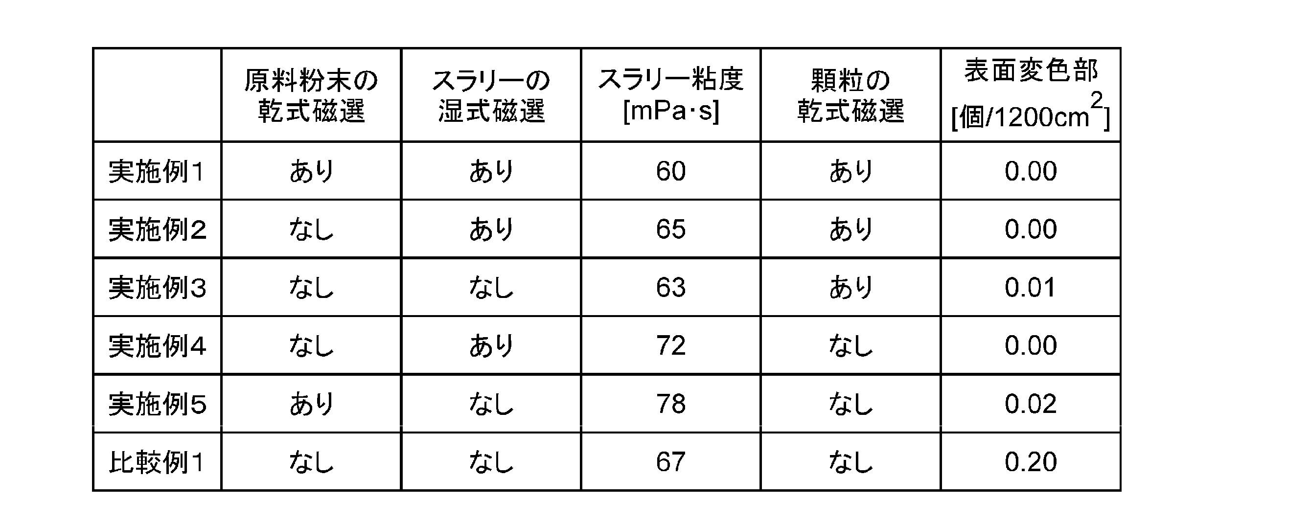
- the results of the production conditions and the rate of occurrence of surface discoloration are shown in Table 1 below.
- the manufactured IGZO cylindrical sputtering target material was bonded to a titanium base material using indium as a bonding material to obtain an IGZO cylindrical sputtering target having no surface discoloration of 1000 ⁇ m 2 or more.
- Example 2 An IGZO cylindrical sputtering target material was produced in the same manner as in Example 1 except that the raw material powder was not subjected to magnetic separation. Evaluation similar to Example 1 was performed about this sputtering target material. The results are shown in Table 1.
- Example 3 An IGZO cylindrical sputtering target material was produced in the same manner as in Example 1 except that the raw material powder and the slurry were not subjected to magnetic separation. Evaluation similar to Example 1 was performed about this sputtering target material. The results are shown in Table 1. Among the manufactured IGZO cylindrical sputtering target materials, a target material having no surface discoloration part of 1000 ⁇ m 2 or more is joined to a titanium base material using indium as a joining material, and a surface discoloration part of 1000 ⁇ m 2 or more is present. A nonexistent IGZO cylindrical sputtering target was obtained.
- Example 4 An IGZO cylindrical sputtering target material was produced in the same manner as in Example 1 except that the raw material powder and the granulated powder were not subjected to magnetic separation. Evaluation similar to Example 1 was performed about this sputtering target material. The results are shown in Table 1.
- Example 5 An IGZO cylindrical sputtering target material was produced in the same manner as in Example 1 except that the slurry and the granulated powder were not subjected to magnetic separation. Evaluation similar to Example 1 was performed about this sputtering target material. The results are shown in Table 1.
- iron can be prevented from being mixed into the thin film, and the manufacturing yield of the oxide semiconductor element can be improved.
Landscapes
- Chemical & Material Sciences (AREA)
- Engineering & Computer Science (AREA)
- Ceramic Engineering (AREA)
- Manufacturing & Machinery (AREA)
- Organic Chemistry (AREA)
- Materials Engineering (AREA)
- Structural Engineering (AREA)
- Inorganic Chemistry (AREA)
- Chemical Kinetics & Catalysis (AREA)
- Mechanical Engineering (AREA)
- Metallurgy (AREA)
- Physical Vapour Deposition (AREA)
- Compositions Of Oxide Ceramics (AREA)
Abstract
Description
酸化物円筒形焼結体は、In、Ga、Zn、Sn及びAlからなる群から選択される少なくとも1種の酸化物を含む焼結体である。酸化物円筒形焼結体は、その相対密度に特に制限はないが、相対密度が高いほどスパッタリング装置の真空系への影響が小さく、良好な薄膜を形成するのに有利である。この観点から、相対密度が90%以上であることが好ましく、更に好ましくは95%以上、一層好ましくは98.0%以上である。相対密度は後述する実施例に記載の方法で測定される。
酸化物円筒形スパッタリングターゲット材は、前記の酸化物円筒形焼結体からなる。酸化物円筒形スパッタリングターゲット材は、酸化物円筒形焼結体に適宜加工を施すことによって作製される。例えば切削加工等を施すことにより作製される。酸化物円筒形スパッタリングターゲット材は、その大きさに特に制限はないが、外径が140mm以上170mm以下であることが好ましく、内径が110mm以上140mm以下であることが好ましく、長さが50mm以上であることが好ましい。長さは用途に応じて適宜決定される。
前記の酸化物円筒形スパッタリングターゲット材を、接合材によって基材に接合することで酸化物円筒形スパッタリングターゲットが得られる。基材は、通常、円筒形スパッタリングターゲット材を接合し得る円筒形状を有する。基材の種類に特に制限はなく、従来使用されている基材を適宜選択して使用することができる。基材の材料としては、例えばステンレス、チタン及び銅等を挙げることができる。接合材の種類にも特に制限はなく、従来使用されている接合材を適宜選択して使用することができる。接合材としては、例えばインジウム製の半田等が挙げられる。
酸化物円筒形焼結体は、好適には原料粉末を粉砕、分級及び混合する工程を含む方法によって製造される。この工程のいずれかの段階において、不純物である鉄が混入する可能性がある。詳細には、鉄は、前記粉砕、分級及び混合のうちの少なくとも一つの工程において混入するか、あるいは元々原料粉末に含まれている。どのような理由によって混入した場合であっても、鉄を磁石に引きつけて除去する磁選を行うことが有利である。なお本発明において「磁選」とは、鉄等の、磁石に付着する不純物を除去する工程を指す。磁選を行うことにより、鉄だけに限られず、Ni及びその合金や酸化物、Co及びその合金や酸化物など磁石に付着する他の不純物も当然除去することができる。
(A)原料粉末の磁選、
(B)原料粉末を粉砕、分級、混合などの処理を実施する工程を含む場合は処理後の粉末の磁選、
(C)原料粉末及び有機添加物を含有するスラリーを作製する工程を含む場合はスラリーの磁選、
(D)前記スラリーから造粒粉を製造する工程を含む場合は造粒粉の磁選、
などが挙げられる。上述した中でも特に(C)スラリーの磁選をすることが好ましい。スラリーのように溶媒中に分散させた状態で磁選を実施した方が、含まれている鉄が磁石へ近づきやすく、磁選効率が高くなり有利である。スラリーを磁選する場合、スラリーの粘度は、磁選時の温度において200mPa・s以下であることが好ましい。スラリーの粘度が200mPa・sを超えると、スラリーが磁選機を通過しにくくなることがあり、またスラリーに含まれている鉄が磁石へ近づきにくくなる傾向がある。以上の理由により、スラリーの粘度は100mPa・s以下であることが更に好ましく、80mPa・s以下であることが特に好ましい。スラリーの粘度の下限値は特に定めるものではないが、通常1mPa・s以上である。
また各工程での磁選回数は1回に限定されるものではない。例えば磁選を実施したスラリーを更に磁選するなど、複数回磁選を実施することで磁選効率を高くすることができるので有利である。
工程1では、原料粉末及び有機添加物を含有するスラリーから造粒粉を製造する。原料粉末としては、例えばIn2O3粉末、Ga2O3粉末、ZnO粉末、SnO2粉末、及びAl2O3粉末のうちのいずれか1種又は任意の2種以上の粉末の混合粉末を使用できる。混合粉末を用いる場合には、各粉末の混合比率は、本酸化物円筒形焼結体における構成元素の含有量により適宜決定される。例えば、最終的に得られる焼結体が原子比でIn:Ga:Zn:O=1:1:1:4である場合には、焼結体におけるIn、Ga、Zn、Oの含有量が原子比1:1:1:4になるように、原料粉末に含まれる各原料粉末の比率が決定される。また、あらかじめ反応、固溶した粉末を単独で使用することができ、その場合には、例えば最終的に得られる焼結体が原子比でIn:Ga:Zn:O=1:1:1:4であるときには、含有量が原子比でIn:Ga:Zn:O=1:1:1:4であるIGZO粉末を単独で用いることができる。本製造方法においては、原料粉末における各元素の比率が、最終的に得られる焼結体及びターゲット材における各元素の比率と同視することができる。
工程2では、工程1で得られた顆粒をCIP成形(冷間等方圧成形)して円筒形の成形体を作製する。CIP成形時の圧力は、通常800kgf/cm2以上である。圧力が高いほど緻密な成形体を得ることができ、それによって成形体を高密度化及び高強度化できる。
工程3では、工程2で作製された成形体を脱脂する。脱脂は一般に成形体を加熱することにより行われる。脱脂温度は、通常600℃以上800℃以下であることが好ましく、700℃以上800℃以下であることが更に好ましく、750℃以上800℃以下であることが一層好ましい。脱脂温度が高いほど成形体の強度が高くなるが、800℃を超えると成形体の収縮が起こる場合があるので、800℃以下で脱脂することが好ましい。
工程4、すなわち焼成工程では、工程3で脱脂された成形体を焼成する。焼成に用いられる焼成炉に特に制限はなく、酸化物焼結体の製造に従来使用されている焼成炉を使用することができる。焼成温度は、通常1300℃以上1700℃以下であることが好ましい。焼成時間は、焼成温度がこの範囲内であることを条件として、通常3時間以上30時間以下である。焼成の雰囲気は通常、大気あるいは酸素雰囲気である。
以下に述べる実施例及び比較例において得られた酸化物焼結体の評価方法は以下のとおりである。
酸化物焼結体の相対密度はアルキメデス法に基づき測定した。具体的には、酸化物焼結体の空中質量を体積(酸化物焼結体の水中質量/計測温度における水比重)で除し、下記の式(1)に基づく理論密度ρ(g/cm3)に対する百分率の値を相対密度(単位:%)とした。
式(1)中、C1~Ciはそれぞれ焼結体の構成物質の酸化物換算での含有量(質量%)を示し、ρ1~ρiはC1~Ciに対応する構成物質の酸化物での密度(g/cm3)を示す。

磁選機に通過させる前のスラリーを採取しスラリーの粘度を測定した。スラリーの粘度はスパイラル粘度計(株式会社マルコム製、PC-10C)を使用して測定した。
酸化物焼結体に鉄が混入し、ターゲット表面に鉄が露出した場合、鉄が含まれる部分は酸化されて赤く変色する。酸化物表面にすべての鉄が析出するわけではないが、本発明においては表面に現れる変色部の割合を尺度として、混入した鉄の量の相対評価とした。変色部はターゲット表面1m2の中に面積1000μm2以上の変色部が何ヵ所発生しているかを目視にて確認した。
BET法により測定された比表面積がいずれも5m2/gであるIn2O3粉末、Ga2O3粉末、ZnO粉末を、In:Ga:Zn:Oの原子比が1:1:1:4になるように配合して混合粉末を得た。この混合粉末をポット中でジルコニアボールによってボールミル混合して、IGZO原料粉末を作製した。
製造したIGZO円筒形スパッタリングターゲット材をチタン製の基材にインジウムを接合材として使用して接合し、1000μm2以上の表面変色部が存在しないIGZO円筒形スパッタリングターゲットを得た。
原料粉末を磁選処理に付さなかった以外は実施例1と同様にしてIGZO円筒形スパッタリングターゲット材を製造した。このスパッタリングターゲット材について実施例1と同様の評価を行った。その結果を表1に示す。
原料粉末及びスラリーを磁選処理に付さなかった以外は実施例1と同様にしてIGZO円筒形スパッタリングターゲット材を製造した。このスパッタリングターゲット材について実施例1と同様の評価を行った。その結果を表1に示す。
製造したIGZO円筒形スパッタリングターゲット材のうち、1000μm2以上の表面変色部が存在しないターゲット材を、チタン製の基材にインジウムを接合材として使用して接合し、1000μm2以上の表面変色部が存在しないIGZO円筒形スパッタリングターゲットを得た。
原料粉末及び造粒粉を磁選処理に付さなかった以外は実施例1と同様にしてIGZO円筒形スパッタリングターゲット材を製造した。このスパッタリングターゲット材について実施例1と同様の評価を行った。その結果を表1に示す。
スラリー及び造粒粉を磁選処理に付さなかった以外は実施例1と同様にしてIGZO円筒形スパッタリングターゲット材を製造した。このスパッタリングターゲット材について実施例1と同様の評価を行った。その結果を表1に示す。
磁選処理を一切行わなかった以外は実施例1と同様にしてIGZO円筒形スパッタリングターゲット材を製造した。このスパッタリングターゲット材について実施例1と同様の評価を行った。その結果を表1に示す。
Claims (12)
- In、Ga、Zn、Sn及びAlからなる群から選択される少なくとも1種の酸化物を含むスパッタリングターゲット材であって、
鉄に由来する、面積1000μm2以上の変色部を表面に有さないか、又は鉄に由来する、面積1000μm2以上の変色部を表面に有する場合には、その割合が0.02個/1200cm2以下であるスパッタリングターゲット材。 - 請求項1に記載のスパッタリングターゲット材と、基材とを備えてなるスパッタリングターゲット。
- 面積1000μm2以上の変色部を表面に有さない請求項1に記載のスパッタリングターゲット材と、基材とを備えてなるスパッタリングターゲット。
- In、Ga、Zn、Sn及びAlからなる群から選択される少なくとも1種の酸化物を含むスパッタリングターゲット材の製造方法であって、
前記スパッタリングターゲット材の製造工程に少なくとも1度の磁選工程を含む、スパッタリングターゲットの製造方法。 - 前記スパッタリングターゲット材の原料粉末を磁選する工程を含む請求項4に記載のスパッタリングターゲット材の製造方法。
- 前記酸化物を含むスラリーを作製する工程と、該スラリーを磁選する工程とを含む請求項4に記載のスパッタリングターゲット材の製造方法。
- 前記酸化物を含むスラリーを作製する工程と、該スラリーから造粒粉を製造する工程と、該造粒粉を磁選する工程とを含む請求項4に記載のスパッタリングターゲット材の製造方法。
- 前記スパッタリングターゲット材の原料粉末を磁選する工程と、前記酸化物を含むスラリーを作製する工程と、該スラリーを磁選する工程とを含む請求項4に記載のスパッタリングターゲット材の製造方法。
- 前記スパッタリングターゲット材の原料粉末を磁選する工程と、前記酸化物を含むスラリーを作製する工程と、該スラリーから造粒粉を製造する工程と、該造粒粉を磁選する工程とを含む請求項4に記載のスパッタリングターゲット材の製造方法。
- 前記酸化物を含むスラリーを作製する工程と、該スラリーを磁選する工程と、該磁選したスラリーから造粒粉を製造する工程と、該造粒粉を磁選する工程とを含む請求項4に記載のスパッタリングターゲット材の製造方法。
- 前記スパッタリングターゲット材の原料粉末を磁選する工程と、前記酸化物を含むスラリーを作製する工程と、該スラリーを磁選する工程と、該磁選したスラリーから造粒粉を製造する工程と、該造粒粉を磁選する工程とを含む請求項4に記載のスパッタリングターゲット材の製造方法。
- 前記スラリーの粘度が200mPa・s以下である請求項6ないし11のいずれか一項に記載のスパッタリングターゲット材の製造方法。
Priority Applications (3)
| Application Number | Priority Date | Filing Date | Title |
|---|---|---|---|
| JP2018508402A JP6894886B2 (ja) | 2016-03-28 | 2016-12-28 | スパッタリングターゲット材及びその製造方法、並びにスパッタリングターゲット |
| CN201680082262.4A CN108699675B (zh) | 2016-03-28 | 2016-12-28 | 溅射靶材和其制造方法以及溅射靶 |
| KR1020187023884A KR102732359B1 (ko) | 2016-03-28 | 2016-12-28 | 스퍼터링 타깃재 및 그의 제조 방법, 및 스퍼터링 타깃 |
Applications Claiming Priority (2)
| Application Number | Priority Date | Filing Date | Title |
|---|---|---|---|
| JP2016064641 | 2016-03-28 | ||
| JP2016-064641 | 2016-03-28 |
Publications (1)
| Publication Number | Publication Date |
|---|---|
| WO2017168906A1 true WO2017168906A1 (ja) | 2017-10-05 |
Family
ID=59963905
Family Applications (1)
| Application Number | Title | Priority Date | Filing Date |
|---|---|---|---|
| PCT/JP2016/089114 Ceased WO2017168906A1 (ja) | 2016-03-28 | 2016-12-28 | スパッタリングターゲット材及びその製造方法、並びにスパッタリングターゲット |
Country Status (5)
| Country | Link |
|---|---|
| JP (1) | JP6894886B2 (ja) |
| KR (1) | KR102732359B1 (ja) |
| CN (1) | CN108699675B (ja) |
| TW (1) | TWI772284B (ja) |
| WO (1) | WO2017168906A1 (ja) |
Cited By (4)
| Publication number | Priority date | Publication date | Assignee | Title |
|---|---|---|---|---|
| WO2019131876A1 (ja) * | 2017-12-28 | 2019-07-04 | 三井金属鉱業株式会社 | 酸化物焼結体、スパッタリングターゲットおよび酸化物薄膜 |
| JP2020001940A (ja) * | 2018-06-25 | 2020-01-09 | 株式会社トクヤマ | セラミック製造用顆粒の製造方法 |
| WO2020241227A1 (ja) * | 2019-05-30 | 2020-12-03 | 株式会社コベルコ科研 | 酸化物焼結体及びスパッタリングターゲット |
| JP2020196660A (ja) * | 2019-05-30 | 2020-12-10 | 株式会社コベルコ科研 | 酸化物焼結体及びスパッタリングターゲット |
Citations (7)
| Publication number | Priority date | Publication date | Assignee | Title |
|---|---|---|---|---|
| JP2009108400A (ja) * | 2007-10-29 | 2009-05-21 | Heraeus Inc | ルテニウム(Ru)及びルテニウム(Ru)合金蒸着ターゲットを再利用する方法、及び再生されたルテニウム(Ru)及びルテニウム(Ru)ベース合金の粉末から作られたターゲット |
| JP2009197310A (ja) * | 2008-02-25 | 2009-09-03 | Kobe Steel Ltd | スパッタリングターゲット |
| JP2013147368A (ja) * | 2012-01-18 | 2013-08-01 | Mitsui Mining & Smelting Co Ltd | セラミックス円筒形スパッタリングターゲット材およびその製造方法 |
| JP2013184882A (ja) * | 2012-03-12 | 2013-09-19 | Mitsui Mining & Smelting Co Ltd | ガリウム・インジウム複合酸化物粉末 |
| JP2015129348A (ja) * | 2015-01-23 | 2015-07-16 | Jx日鉱日石金属株式会社 | 透明電極膜及び同電極膜を形成するためのスパッタリングターゲット |
| JP2015214437A (ja) * | 2014-05-08 | 2015-12-03 | 出光興産株式会社 | 酸化物焼結体及びスパッタリングターゲット |
| JP2016033092A (ja) * | 2014-07-30 | 2016-03-10 | 住友金属鉱山株式会社 | 酸化物焼結体とその製造方法、および、この酸化物焼結体を用いたスパッタリングターゲット |
Family Cites Families (6)
| Publication number | Priority date | Publication date | Assignee | Title |
|---|---|---|---|---|
| JP2007138198A (ja) * | 2005-11-15 | 2007-06-07 | Tateho Chem Ind Co Ltd | 蒸着材用酸化マグネシウム焼結体 |
| JP2009256719A (ja) * | 2008-04-16 | 2009-11-05 | Hirasho:Kk | スパッタリングターゲット |
| CN101445270A (zh) * | 2008-10-20 | 2009-06-03 | 雷亚林 | 高纯金红石纳米二氧化钛制备 |
| JP5546143B2 (ja) * | 2009-03-03 | 2014-07-09 | 住友電気工業株式会社 | 透明薄膜形成用の複合酸化物焼結体及び透明薄膜形成用材料 |
| CN102686766B (zh) | 2010-11-08 | 2014-04-09 | 三井金属矿业株式会社 | 分割溅镀靶及其制造方法 |
| WO2014073585A1 (en) * | 2012-11-08 | 2014-05-15 | Semiconductor Energy Laboratory Co., Ltd. | Metal oxide film and method for forming metal oxide film |
-
2016
- 2016-12-28 CN CN201680082262.4A patent/CN108699675B/zh active Active
- 2016-12-28 WO PCT/JP2016/089114 patent/WO2017168906A1/ja not_active Ceased
- 2016-12-28 KR KR1020187023884A patent/KR102732359B1/ko active Active
- 2016-12-28 JP JP2018508402A patent/JP6894886B2/ja active Active
-
2017
- 2017-01-10 TW TW106100694A patent/TWI772284B/zh active
Patent Citations (7)
| Publication number | Priority date | Publication date | Assignee | Title |
|---|---|---|---|---|
| JP2009108400A (ja) * | 2007-10-29 | 2009-05-21 | Heraeus Inc | ルテニウム(Ru)及びルテニウム(Ru)合金蒸着ターゲットを再利用する方法、及び再生されたルテニウム(Ru)及びルテニウム(Ru)ベース合金の粉末から作られたターゲット |
| JP2009197310A (ja) * | 2008-02-25 | 2009-09-03 | Kobe Steel Ltd | スパッタリングターゲット |
| JP2013147368A (ja) * | 2012-01-18 | 2013-08-01 | Mitsui Mining & Smelting Co Ltd | セラミックス円筒形スパッタリングターゲット材およびその製造方法 |
| JP2013184882A (ja) * | 2012-03-12 | 2013-09-19 | Mitsui Mining & Smelting Co Ltd | ガリウム・インジウム複合酸化物粉末 |
| JP2015214437A (ja) * | 2014-05-08 | 2015-12-03 | 出光興産株式会社 | 酸化物焼結体及びスパッタリングターゲット |
| JP2016033092A (ja) * | 2014-07-30 | 2016-03-10 | 住友金属鉱山株式会社 | 酸化物焼結体とその製造方法、および、この酸化物焼結体を用いたスパッタリングターゲット |
| JP2015129348A (ja) * | 2015-01-23 | 2015-07-16 | Jx日鉱日石金属株式会社 | 透明電極膜及び同電極膜を形成するためのスパッタリングターゲット |
Cited By (6)
| Publication number | Priority date | Publication date | Assignee | Title |
|---|---|---|---|---|
| WO2019131876A1 (ja) * | 2017-12-28 | 2019-07-04 | 三井金属鉱業株式会社 | 酸化物焼結体、スパッタリングターゲットおよび酸化物薄膜 |
| JPWO2019131876A1 (ja) * | 2017-12-28 | 2020-12-10 | 三井金属鉱業株式会社 | 酸化物焼結体、スパッタリングターゲットおよび酸化物薄膜 |
| JP7269886B2 (ja) | 2017-12-28 | 2023-05-09 | 三井金属鉱業株式会社 | 酸化物焼結体、スパッタリングターゲットおよび酸化物薄膜 |
| JP2020001940A (ja) * | 2018-06-25 | 2020-01-09 | 株式会社トクヤマ | セラミック製造用顆粒の製造方法 |
| WO2020241227A1 (ja) * | 2019-05-30 | 2020-12-03 | 株式会社コベルコ科研 | 酸化物焼結体及びスパッタリングターゲット |
| JP2020196660A (ja) * | 2019-05-30 | 2020-12-10 | 株式会社コベルコ科研 | 酸化物焼結体及びスパッタリングターゲット |
Also Published As
| Publication number | Publication date |
|---|---|
| TW201734233A (zh) | 2017-10-01 |
| KR102732359B1 (ko) | 2024-11-22 |
| CN108699675B (zh) | 2022-01-11 |
| KR20180129769A (ko) | 2018-12-05 |
| CN108699675A (zh) | 2018-10-23 |
| JPWO2017168906A1 (ja) | 2019-02-07 |
| TWI772284B (zh) | 2022-08-01 |
| JP6894886B2 (ja) | 2021-06-30 |
Similar Documents
| Publication | Publication Date | Title |
|---|---|---|
| JP2013147368A (ja) | セラミックス円筒形スパッタリングターゲット材およびその製造方法 | |
| WO2017168906A1 (ja) | スパッタリングターゲット材及びその製造方法、並びにスパッタリングターゲット | |
| CN114874004B (zh) | 一种高熵六角铁氧体陶瓷及其制备方法 | |
| KR102493208B1 (ko) | 원통형 스퍼터링 타겟, 원통형 성형체, 및 원통형 스퍼터링 타겟, 원통형 소결체, 및 원통형 성형체의 제조 방법 | |
| KR20180093140A (ko) | Ito 스퍼터링 타겟 및 그 제조 방법 그리고 ito 투명 도전막 및 ito 투명 도전막의 제조 방법 | |
| JP2023067117A (ja) | Igzoスパッタリングターゲット | |
| TWI778100B (zh) | 氧化物燒結體及濺鍍靶 | |
| JP6144858B1 (ja) | 酸化物焼結体およびスパッタリングターゲット、並びにそれらの製造方法 | |
| JP6254308B2 (ja) | 酸化物焼結体およびスパッタリングターゲット、並びにそれらの製造方法 | |
| JP2023124649A (ja) | スパッタリングターゲット部材及びスパッタリングターゲット部材の製造方法 | |
| JP5784849B2 (ja) | セラミックス円筒形スパッタリングターゲット材およびその製造方法 | |
| WO2018179556A1 (ja) | スパッタリングターゲット及びその製造方法 | |
| WO2017141558A1 (ja) | 磁気記録媒体用スパッタリングターゲット及び磁性薄膜 | |
| WO2015068564A1 (ja) | スパッタリングターゲット | |
| JP7282766B2 (ja) | 酸化物焼結体およびスパッタリングターゲット | |
| WO2019202753A1 (ja) | 酸化物焼結体、スパッタリングターゲットおよび酸化物薄膜の製造方法 | |
| JP5800209B2 (ja) | 酸化物スパッタリングターゲットおよびその製造方法 | |
| JP7723218B2 (ja) | 酸化物焼結体 | |
| JP2016014191A (ja) | セラミックス円筒形スパッタリングターゲット材およびその製造方法 | |
| WO2017183263A1 (ja) | 酸化物焼結体およびスパッタリングターゲット、並びにそれらの製造方法 | |
| JP2025114831A (ja) | 酸化物焼結体の製造方法 | |
| JP6883431B2 (ja) | LiCoO2焼結体およびその製造方法 | |
| JP6364562B1 (ja) | 酸化物焼結体およびスパッタリングターゲット |
Legal Events
| Date | Code | Title | Description |
|---|---|---|---|
| WWE | Wipo information: entry into national phase |
Ref document number: 2018508402 Country of ref document: JP |
|
| ENP | Entry into the national phase |
Ref document number: 20187023884 Country of ref document: KR Kind code of ref document: A |
|
| NENP | Non-entry into the national phase |
Ref country code: DE |
|
| 121 | Ep: the epo has been informed by wipo that ep was designated in this application |
Ref document number: 16897121 Country of ref document: EP Kind code of ref document: A1 |
|
| 122 | Ep: pct application non-entry in european phase |
Ref document number: 16897121 Country of ref document: EP Kind code of ref document: A1 |