WO2017168857A1 - レーザ加工機 - Google Patents
レーザ加工機 Download PDFInfo
- Publication number
- WO2017168857A1 WO2017168857A1 PCT/JP2016/086974 JP2016086974W WO2017168857A1 WO 2017168857 A1 WO2017168857 A1 WO 2017168857A1 JP 2016086974 W JP2016086974 W JP 2016086974W WO 2017168857 A1 WO2017168857 A1 WO 2017168857A1
- Authority
- WO
- WIPO (PCT)
- Prior art keywords
- lens
- laser
- variable device
- diameter
- laser light
- Prior art date
Links
Images


Classifications
-
- B—PERFORMING OPERATIONS; TRANSPORTING
- B23—MACHINE TOOLS; METAL-WORKING NOT OTHERWISE PROVIDED FOR
- B23K—SOLDERING OR UNSOLDERING; WELDING; CLADDING OR PLATING BY SOLDERING OR WELDING; CUTTING BY APPLYING HEAT LOCALLY, e.g. FLAME CUTTING; WORKING BY LASER BEAM
- B23K26/00—Working by laser beam, e.g. welding, cutting or boring
- B23K26/02—Positioning or observing the workpiece, e.g. with respect to the point of impact; Aligning, aiming or focusing the laser beam
- B23K26/06—Shaping the laser beam, e.g. by masks or multi-focusing
- B23K26/064—Shaping the laser beam, e.g. by masks or multi-focusing by means of optical elements, e.g. lenses, mirrors or prisms
- B23K26/0648—Shaping the laser beam, e.g. by masks or multi-focusing by means of optical elements, e.g. lenses, mirrors or prisms comprising lenses
-
- B—PERFORMING OPERATIONS; TRANSPORTING
- B23—MACHINE TOOLS; METAL-WORKING NOT OTHERWISE PROVIDED FOR
- B23K—SOLDERING OR UNSOLDERING; WELDING; CLADDING OR PLATING BY SOLDERING OR WELDING; CUTTING BY APPLYING HEAT LOCALLY, e.g. FLAME CUTTING; WORKING BY LASER BEAM
- B23K26/00—Working by laser beam, e.g. welding, cutting or boring
- B23K26/02—Positioning or observing the workpiece, e.g. with respect to the point of impact; Aligning, aiming or focusing the laser beam
- B23K26/04—Automatically aligning, aiming or focusing the laser beam, e.g. using the back-scattered light
- B23K26/046—Automatically focusing the laser beam
-
- B—PERFORMING OPERATIONS; TRANSPORTING
- B23—MACHINE TOOLS; METAL-WORKING NOT OTHERWISE PROVIDED FOR
- B23K—SOLDERING OR UNSOLDERING; WELDING; CLADDING OR PLATING BY SOLDERING OR WELDING; CUTTING BY APPLYING HEAT LOCALLY, e.g. FLAME CUTTING; WORKING BY LASER BEAM
- B23K26/00—Working by laser beam, e.g. welding, cutting or boring
- B23K26/02—Positioning or observing the workpiece, e.g. with respect to the point of impact; Aligning, aiming or focusing the laser beam
- B23K26/06—Shaping the laser beam, e.g. by masks or multi-focusing
-
- B—PERFORMING OPERATIONS; TRANSPORTING
- B23—MACHINE TOOLS; METAL-WORKING NOT OTHERWISE PROVIDED FOR
- B23K—SOLDERING OR UNSOLDERING; WELDING; CLADDING OR PLATING BY SOLDERING OR WELDING; CUTTING BY APPLYING HEAT LOCALLY, e.g. FLAME CUTTING; WORKING BY LASER BEAM
- B23K26/00—Working by laser beam, e.g. welding, cutting or boring
- B23K26/36—Removing material
- B23K26/38—Removing material by boring or cutting
Definitions
- This disclosure relates to a laser processing machine that cuts a metal plate with laser light.
- Laser processing machines that cut a metal plate material with laser light emitted from a laser oscillator have become widespread.
- Various laser oscillators are used in the laser processing machine.
- a fiber laser oscillator is often used to cut a plate material having a relatively small thickness at high speed.
- the fiber laser oscillator has an advantage that it is small and low-cost as compared with the CO 2 laser oscillator in addition to the advantage that it is suitable for high-speed cutting of a plate material.
- a plate material having a plate thickness of 6 mm to 30 mm is referred to as a thick plate
- a plate material having a plate thickness of, for example, 0.1 mm to 6 mm is referred to as a thin plate.
- a plate material having a plate thickness of 2 mm to 12 mm may be referred to as a medium plate. It is difficult to cut a thick plate and a thin plate by changing only the processing conditions with the same laser processing machine.
- the processing conditions here are, for example, the power of the laser beam, the duty of the pulse when the laser beam is pulse-oscillated, the focal position, the type of assist gas, or the gas pressure.
- optical system elements such as lenses or components of the laser processing machine such as a processing nozzle must be replaced. Since the replacement of the component parts is complicated and causes an increase in cost, a laser beam machine capable of cutting both the thick plate and the thin plate without replacing the component parts is desired.
- Embodiment aims at providing the laser processing machine which can cut
- a beam parameter product variable device that varies the beam parameter product of the laser light emitted from the laser oscillator, and a beam that varies the beam diameter of the laser light emitted from the beam parameter product variable device.
- the beam parameter product variable device sets the beam parameter product of the laser beam to a predetermined value, and the beam diameter variable device is movable in the optical axis direction and has a positive focus.
- the beam diameter variable device is arranged at a position shifted by the same distance as the focal length of the second lens, and is configured to convert the convergent light into parallel light, and has a positive focal length
- a laser processing machine further comprising a third lens that collects the emitted laser light and irradiates the plate material.
- the first moving mechanism for moving the first lens, the second moving mechanism for moving the second lens, and the first moving mechanism are driven.
- control unit controls the beam parameter product varying device so as to vary a beam parameter product of laser light.
- the control unit increases the beam diameter of the laser light incident on the third lens so that the condensing diameter decreases as the plate thickness of the plate material decreases, and the condensing diameter increases as the plate thickness of the plate material increases.
- the first and second driving units are controlled so as to reduce the beam diameter of the laser light incident on the third lens so as to increase. Even if the first and second driving units move the first and second lenses, the focal position of the laser light emitted from the third lens and condensed on the plate material is constant.
- the third lens is configured to be movable in the optical axis direction and to change the focal position of the laser light.
- a first movement mechanism for moving the first lens a second movement mechanism for moving the second lens, and a movement of the third lens.
- a third driving mechanism a first driving section for driving the first moving mechanism, a second driving section for driving the second moving mechanism, and a second driving section for driving the third moving mechanism. 3, the first lens, the second lens, and the third lens so as to move according to the processing conditions of the plate material.
- a control unit for controlling the third drive unit.
- control unit controls the beam parameter product varying device so as to vary a beam parameter product of laser light.
- the laser processing machine of the embodiment it is possible to cut and process a plate material having a thickness in a predetermined range without exchanging components.
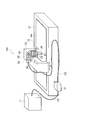
- FIG. 1 is a perspective view showing an example of the overall configuration of a laser beam machine according to an embodiment.
- FIG. 2 is a diagram showing a schematic configuration when the laser oscillator 11 in FIG. 1 is configured by a fiber laser oscillator 11F.
- FIG. 3 is a diagram showing a schematic configuration when the laser oscillator 11 in FIG. 1 is configured by a direct diode laser oscillator 11D.
- FIG. 4 is a diagram illustrating a configuration example of the beam parameter product variable device 31 in FIG.
- FIG. 5 is a diagram illustrating a schematic configuration example in which the convex lens 28, the concave lens 30, and the condenser lens 27 in FIG. 1 are movable.
- FIG. 1 is a perspective view showing an example of the overall configuration of a laser beam machine according to an embodiment.
- FIG. 2 is a diagram showing a schematic configuration when the laser oscillator 11 in FIG. 1 is configured by a fiber laser oscillator 11F.
- FIG. 3 is a diagram showing
- FIG. 6 is a diagram for explaining how to move the convex lens 28, the concave lens 30, and the condenser lens 27.
- FIG. 7 is a diagram for explaining the condensing diameter and the divergence angle of the laser light.
- FIG. 8 is a diagram for explaining the operation of the beam parameter product variable device 31.
- a laser beam machine 100 generates a laser beam and emits it, and a beam parameter product variable device 31 that varies a beam parameter product (BeamBeParameter Products) of the laser beam emitted from the laser oscillator 11. And a laser processing unit 15.
- the beam parameter product is referred to as BPP
- the beam parameter product variable device 31 is referred to as BPP product variable device 31.
- the laser oscillator 11 and the BPP product variable device 31 are connected by a feeding fiber 121, and the feeding fiber 121 transmits the laser light emitted from the laser oscillator 11 to the BPP product variable device 31.
- the BPP product variable device 31 and the laser processing unit 15 are connected by a process fiber 122, and the process fiber 122 transmits the laser light emitted from the BPP product variable device 31 to the laser processing unit 15.
- the process fiber 122 is mounted along X-axis and Y-axis cable ducts (not shown) arranged in the laser processing unit 15.
- the laser processing machine 100 cuts and processes the metal plate material W1 with the laser light emitted from the laser oscillator 11.
- the laser oscillator 11 is preferably a laser oscillator that amplifies excitation light emitted from a laser diode and emits laser light having a predetermined wavelength, or a laser oscillator that directly uses laser light emitted from a laser diode.
- the laser oscillator 11 is, for example, a solid laser oscillator, a fiber laser oscillator, a disk laser oscillator, or a direct diode laser oscillator (DDL oscillator).
- the laser processing unit 15 includes a processing table 21 on which the plate material W1 is placed, a portal X-axis carriage 22 that is movable in the X-axis direction on the processing table 21, and a Y-axis that is perpendicular to the X-axis on the X-axis carriage 22 And a Y-axis carriage 23 that is movable in the direction. Further, the laser processing unit 15 has a collimator unit 29 fixed to the Y-axis carriage 23.
- the collimator unit 29 has a convex lens 28 into which laser light emitted from the exit end of the process fiber 122 is incident, and a concave lens 30 into which laser light emitted from the convex lens 28 is incident.
- the collimator unit 29 also reflects a laser beam emitted from the concave lens 30 toward the lower side in the Z-axis direction perpendicular to the X-axis and the Y-axis, and a collector that collects the laser beam reflected by the bend mirror 25.
- An optical lens 27 and a processing head 26 are included.
- the convex lens 28 is a lens having a positive focal length
- the concave lens 30 is a lens having a negative focal length
- the condenser lens 27 is a lens having a positive focal length.
- the condenser lens 27 is a convex lens.
- the convex lens 28 and the concave lens 30 have a function of a collimating lens that collimates individual beams of incident laser light.
- the convex lens 28, the concave lens 30, and the condenser lens 27 are configured to be movable in the optical axis direction.
- the convex lens 28 and the concave lens 30 constitute a beam diameter varying device 32 (see FIG. 5 or 6) that varies the beam diameter.
- the convex lens 28 and the concave lens 30, the bend mirror 25, the condensing lens 27, and the processing head 26 are disposed in the collimator unit 29 with the optical axis adjusted in advance.
- the collimator unit 29 is fixed to a Y-axis carriage 23 movable in the Y-axis direction, and the Y-axis carriage 23 is provided on an X-axis carriage 22 movable in the X-axis direction. Therefore, the laser processing unit 15 can move the position at which the plate material W1 is irradiated with the laser light emitted from the processing head 26 in the X-axis direction and the Y-axis direction.
- the laser processing machine 100 transmits the laser light emitted from the laser oscillator 11 to the laser processing unit 15 via the BPP product variable device 31 and is collected by the condensing lens 27.
- the plate material W1 can be cut by irradiating the plate material W1.
- the BPP product variable device 31 is provided outside the laser oscillator 11 in FIG. 1, the BPP product variable device 31 may be provided inside the housing of the laser oscillator 11.
- an assist gas for removing the melt is injected onto the plate material W1.
- FIG. 1 the illustration of the configuration for injecting the assist gas is omitted.
- FIG. 2 shows a schematic configuration when the laser oscillator 11 is constituted by a fiber laser oscillator 11F.
- each of the plurality of laser diodes 110 emits laser light having a wavelength ⁇ .
- the excitation combiner 111 combines the laser beams emitted from the plurality of laser diodes 110 with a spatial beam.
- the laser light emitted from the excitation combiner 111 is incident on the Yb-doped fiber 113 between the two fiber Bragg gratings (FBGs) 112 and 114.
- the Yb-doped fiber 113 is a fiber in which a rare earth Yb (ytterbium) element is added to the core.
- the laser light incident on the Yb-doped fiber 113 repeats reciprocation between the FBGs 112 and 114, and laser light having a wavelength ⁇ ′ (1 ⁇ m band) of approximately 1060 nm to 1080 nm, which is different from the wavelength ⁇ , is emitted from the FBG 114.
- Laser light emitted from the FBG 114 is incident on the feeding fiber 121 via the feeding fiber 115 and the beam coupler 116.
- the beam coupler 116 includes lenses 1161 and 1162.
- FIG. 3 shows a schematic configuration when the laser oscillator 11 is constituted by a DDL oscillator 11D.
- a plurality of laser diodes 117 emit laser beams having different wavelengths ⁇ 1 to ⁇ n.
- the wavelengths ⁇ 1 to ⁇ n are, for example, 910 nm to 950 nm.
- the optical box 118 spatially couples laser beams having wavelengths ⁇ 1 to ⁇ n emitted from a plurality of laser diodes 117.
- the optical box 118 includes a collimating lens 1181, a grating 1182, and a condensing lens 1183.
- the collimating lens 1181 collimates laser light with wavelengths ⁇ 1 to ⁇ n.
- the grating 1182 bends the direction of the collimated laser beam by 90 degrees and makes it incident on the condenser lens 1183.
- the condensing lens 1183 condenses the incident laser light and enters the feeding fiber 121.
- the BPP product variable device 31 includes a condensing lens 311 disposed between the exit end of the feeding fiber 121 and the entrance end of the process fiber 122, and a moving mechanism 312 that moves the position of the end of the feeding fiber 121.
- the process fiber 122 has a configuration in which the cladding 1222 covers the periphery of the core 1221.
- the refractive index of the core 1221 is higher than the refractive index of the clad 1222.
- the feeding fiber 121 has the same configuration.
- the incident position of the laser light incident on the condensing lens 311 changes, and the condensing lens 311 becomes the core 1221 of the process fiber 122.
- the incident angle of the laser beam incident on is changed.
- the laser light proceeds as indicated by a solid line
- the laser light proceeds as indicated by a one-dot chain line.
- the BPP of the laser light emitted from the process fiber 122 changes.
- the BPP product variable device 31 is not limited to the configuration shown in FIG. 4 and may be any configuration as long as it can change the BPP.
- the position of the feeding fiber 121 may be fixed, and the incident angle of the laser light incident on the process fiber 122 may be changed by moving the lens.
- a lens may be further provided at the incident end of the process fiber 122.
- the convex lens 28 and the concave lens 30 constituting the beam diameter varying device 32 are respectively movable mechanisms 281 and 301 for making the convex lens 28 and the concave lens 30 movable in the optical axis direction (X-axis direction in FIG. 1). Is attached.
- the condenser lens 27 is attached to a moving mechanism 271 for making the condenser lens 27 movable in the optical axis direction (Z-axis direction in FIG. 1).
- the moving mechanisms 281, 301, and 271 use, for example, any one of a gear, a belt, a rack and pinion, a worm gear, a ball screw, or the like (or any combination thereof), the convex lens 28, the concave lens 30, and the condenser lens 27. Any mechanism can be used as long as it can move freely.
- the convex lens 28, the concave lens 30, and the condenser lens 27 move in the optical axis direction as indicated by arrows by the driving units 282, 302, and 272 driving the moving mechanisms 281, 301, and 271 respectively.
- the drive units 282, 302, and 272 are, for example, motors.
- the control unit 50 controls the drive units 282, 302, and 272.
- the control unit 50 can be configured by a microprocessor.
- the controller 50 may be an NC device that controls the entire laser beam machine 100.
- the operator can set various processing conditions such as the material type of the plate material W1, the plate thickness of the plate material W1, the focused diameter of the laser beam, and the focal position by operating the operation unit 51.
- the material of the plate material W1 is, for example, iron, stainless steel, aluminum, copper, or brass.
- the plate thickness of the plate material W1 is any plate thickness within a predetermined range, for example, with a predetermined range of 0.1 mm to 30 mm.
- the control unit 50 controls driving of the moving mechanisms 281 and 301 by the driving units 282 and 302 so as to adjust the positions of the convex lens 28 and the concave lens 30 in accordance with the processing conditions of the plate material W1 input by the operation unit 51.
- the control unit 50 controls the driving units 282 and 302 so as to adjust the positions of the convex lens 28 and the concave lens 30 according to the input condensing diameter. To do.
- the control unit 50 determines the convex lens 28 and the concave lens 30 according to the light collection diameter corresponding to the input material type and plate thickness.
- the drive units 282 and 302 can be controlled so as to adjust the position.
- the control unit 50 may obtain a necessary condensing diameter by calculation based on processing conditions, or may read out condensing diameters corresponding to the respective processing conditions held in advance.
- control unit 50 controls the driving of the moving mechanism 271 by the driving unit 272 so as to adjust the position of the condenser lens 27 according to the input focal position. .
- laser light is emitted as divergent light from the exit end 122e of the process fiber 122, as indicated by a one-dot chain line.
- the convex lens 28 is disposed such that the distance from the exit end 122e to the convex lens 28 is equal to or less than the focal length of the convex lens 28. Therefore, the convex lens 28 converts the diffused light of the laser light into convergent light.
- the control unit 50 can move the convex lens 28 in the optical axis direction within a range where the distance from the exit end 122e to the convex lens 28 is equal to or less than the focal length of the convex lens 28.
- the concave lens 30 converts convergent light into parallel light.
- the parallel light means that the light beam of the laser light is parallel light.
- the parallel light emitted from the concave lens 30 is reflected by the bend mirror 25, the optical path is bent, and enters the condenser lens 27.
- the condensing lens 27 condenses parallel light so that the focal position is at or near the surface of the plate material W1, and irradiates the plate material W1 with laser light.
- the control unit 50 may control the BPP product variable device 31 to change the BPP.
- FIGS. 6A to 6C conceptually show a state in which the bend mirror 25 in FIG. 5 is omitted and the convex lens 28, the concave lens 30 and the condenser lens 27 are arranged so that the optical axis is in a straight line. ing.
- the position where the concave lens 30 does not exist and the convergent light from the convex lens 28 is focused is a point Pf28.
- the concave lens 30 converts convergent light into parallel light.
- the beam diameter D of the parallel light emitted from the concave lens 30 changes according to the convergence angle of the convergent light emitted from the convex lens.
- FIG. 7 conceptually shows an enlarged view of the vicinity of the beam waste of the laser beam condensed on the surface of the plate material W1 or in the vicinity thereof.
- the left side of FIG. 7 is the upper side of the plate material W1
- the right side is the lower side of the plate material W1.
- the condensing diameter d is expressed by equation (1).
- the Rayleigh length Zr is expressed by equation (2).
- f is the focal length of the condenser lens 27.
- BPP is represented by the product of the beam waste radius d / 2 and the half-width half width ⁇ of the beam divergence angle.
- the converging diameter d and the Rayleigh length Zr are determined according to the beam diameter D from the equations (1) and (2), and when the beam diameter D changes, the condensing diameter d. And the Rayleigh length Zr changes.
- the beam diameter D When the beam diameter D is increased, the condensing diameter d and the Rayleigh length Zr are decreased, the power density is increased, and a beam profile suitable for a thin plate is obtained.
- the beam diameter D When the beam diameter D is reduced, the light condensing diameter d and the Rayleigh length Zr are increased, and the power density is reduced to provide a beam profile suitable for a thick plate.
- the control unit 50 calculates the beam diameter D that is the target focused diameter d based on the formula (1), and the positions of the convex lens 28 and the concave lens 30 are the positions that realize the calculated beam diameter D.
- the driving units 282 and 302 are controlled to move the convex lens 28 and the concave lens 30.
- control unit 50 moves the convex lens 28 so that the convergence angle of the laser light emitted from the convex lens 28 becomes a convergence angle at which a target beam diameter D is obtained.
- control unit 50 shifts the concave lens 30 from the point Pf28 to the convex lens 28 side by a distance L so as to convert the convergent light into parallel light corresponding to the position of the convex lens 28 in the optical axis direction. Move.
- the control unit 50 calculates the positions of the convex lens 28 and the concave lens 30 for setting the target beam diameter D and the focused diameter d, and moves the convex lens 28 and the concave lens 30.
- control unit 50 increases the beam diameter of the laser light incident on the condensing lens 27 so that the condensing diameter decreases as the plate thickness of the plate W1 decreases, and the plate thickness of the plate W1 increases.
- the drive units 282 and 302 are controlled so as to reduce the beam diameter of the laser light incident on the condensing lens 27 so as to increase the condensing diameter. Even if the drive units 282 and 302 move the convex lens 28 and the concave lens 30, the focal position of the laser light emitted from the condenser lens 27 and condensed on the plate material W1 is constant and does not change.
- the light intensity distribution within the beam diameter D is formed by reflection synthesis of laser light transmitted to the core and clad of the process fiber 122. Even if the beam diameter D changes as shown in FIGS. 6A and 6B, the light intensity distribution within the beam diameter D hardly changes, and even if it changes, it is very slight.
- the focal position can be changed as shown in FIG.
- the surface of the plate material W1 is not set as the focal position, but the position slightly shifted from the front surface or the back surface of the plate material W1 is used as a focal position for cutting.
- the control unit 50 controls the driving unit 272 to move the condenser lens 27 so that the input focal position is obtained. Even if the condensing lens 27 is moved to change the focal position, the condensing diameter d does not change.
- the operation of the BPP product variable device 31 will be described with reference to FIGS. 8 (a) to (d).
- the light condensing diameter d and the Rayleigh length Zr vary depending on the BPP.
- the beam diameter D1 shown in FIGS. 8A and 8B is assumed to be the maximum diameter allowed by the condenser lens 27. It is assumed that the control unit 50 controls the BPP product variable device 31 so that the BPP in FIG. 8A is smaller than the BPP in FIG.
- the divergence angle of the beam increases. Therefore, in order to make the beam diameter D common to the beam diameter D1, it is necessary to make the positions of the convex lens 28 and the concave lens 30 different.
- the reason why the positions of the convex lens 28 and the concave lens 30 are different between FIG. 8A and FIG. 8B is that the beam diameter D is shared by the beam diameter D1 while changing the BPP.
- the BPP product variable device 31 makes the BPP in FIG. 8 (a) smaller than the BPP in FIG. 8 (b), so that the condensing diameter d in FIG. 8 (a) is greater than the condensing diameter d in FIG. 8 (b). Can also be reduced. If the light collection diameter d in FIG. 8 (a) is d1, and the light collection diameter d in FIG. 8 (b) is d2, then d1 ⁇ d2.
- the beam diameter D2 shown in FIGS. 8C and 8D is assumed to be the minimum diameter allowable for the condenser lens 27.
- the minimum diameter is determined by the influence of the thermal lens and the light resistance of the condenser lens 27 coating. Assume that the control unit 50 controls the BPP product variable device 31 so that the BPP in FIG. 8D is larger than the BPP in FIG.
- the positions of the convex lens 28 and the concave lens 30 are different between FIG. 8C and FIG. 8D because the beam diameter D is shared by the beam diameter D2 while changing the BPP. .
- the BPP product variable device 31 makes the BPP in FIG. 8 (d) larger than the BPP in FIG. 8 (c), so that the light collection diameter d in FIG. Can also be increased. If the light collection diameter d in FIG. 8C is d3 and the light collection diameter d in FIG. 8D is d4, d3 ⁇ d4.
- the control unit 50 controls the BPP product variable device 31 so that the BPP becomes a predetermined value, and drives 282 and 302 so as to determine the positions of the convex lens 28 and the concave lens 30 so that the desired beam diameter D is obtained. Can be controlled.
- the condensing diameter d can be varied only by the BPP product variable device 31, and only the beam diameter variable device 32 is provided.
- the condensing diameter d can be made different. Further, the condensing diameter d can be made different in both the BPP product variable device 31 and the beam diameter variable device 32.
- the beam diameter D changes in the range from the maximum beam diameter D1 to the minimum beam diameter D2.
- the BPP product variable device 31 changes the value of BPP in the range from BPP1 to BPP2.
- the BPP value is BPP1
- the BPP value is BPP2.
- the condensing diameter d can be changed in the range from d1 to d4 by changing the BPP.
- the condensing diameter d can be changed by changing at least one of the BPP and the beam diameter D. If both the BPP and the beam diameter D are changed, the condensing diameter d can be changed over a wide range.
- the condensing diameter d can be adjusted in a wide range by including the BPP product variable device 31 and the beam diameter variable device 32, the range of the plate thickness that can be appropriately cut and processed. Can be spread.
- variable range of BPP by the BPP product variable device 31 is 1.5 to 5 mm ⁇ mrad (ie, 1 to 3.33 times), and the variable range of the beam diameter D by the beam diameter variable device 32 is 1 to 3 times. From the formula (1), the light collection diameter d can be varied from 1 to 10 times. If the variable range of the BPP is further increased, the condensing diameter d can be varied over a wider range.
- any one of a Gaussian shape and a ring shape can be appropriately selected as the beam shape.
- the beam waste is adjusted according to the plate thickness and material of the plate material W1, and the BPP is adjusted accordingly, so that the distribution of the power density of the laser light applied to the plate material W1 is appropriately adjusted.
- the cut surface roughness of the plate material W1 is improved by appropriately controlling the beam waste and power density distribution and appropriately adjusting the melting time and cutting speed of the plate material W1. Can be.
- the condensing diameter d and the focal position can be adjusted independently of each other.
- the position of the condenser lens 27 may be fixed, and only the convex lens 28 and the concave lens 30 may be configured to be movable.
- the controller 50 may continuously adjust the light collection diameter d according to the plate thickness of the plate material W1. For example, a thick plate with a thickness of 6 mm to 30 mm and a thin plate with a thickness of 0.1 mm to 6 mm may be used.
- the light collection diameter d may be adjusted in two steps. Further, the concentrating diameter d may be adjusted in three stages by dividing the plate thickness of 12 mm to 30 mm, the medium thickness plate of 2 mm to 12 mm, and the plate material of 0.1 mm to 2 mm from the thin plate.
- the control unit 50 may divide the plate thickness of the plate material W1 into four or more groups and adjust the light collection diameter d in four or more steps.
- the plate material W1 having a predetermined range of plate thickness can be adjusted to the respective plate thickness without exchanging components such as lenses. It can be cut properly.
- the first lens having a positive focal length
- the second lens having a negative focal length
- the positive focal length may be used. Therefore, it is possible to simplify the configuration as compared with the configuration described in Patent Document 1, and to realize a laser processing machine capable of cutting a plate material having a predetermined range of thickness at low cost without exchanging components. it can.
- the laser processing machine 100 of the present embodiment it is possible to realize an appropriate cutting process in accordance with the plate thickness by configuring only the first and second lenses to be movable.
- the present invention can be used when cutting a plurality of plate materials with a laser beam.
Landscapes
- Physics & Mathematics (AREA)
- Optics & Photonics (AREA)
- Engineering & Computer Science (AREA)
- Plasma & Fusion (AREA)
- Mechanical Engineering (AREA)
- Laser Beam Processing (AREA)
- Lasers (AREA)
Priority Applications (3)
| Application Number | Priority Date | Filing Date | Title |
|---|---|---|---|
| EP16897073.9A EP3437783B1 (de) | 2016-04-01 | 2016-12-13 | Laserverarbeitungsmaschine |
| US16/089,770 US10583525B2 (en) | 2016-04-01 | 2016-12-13 | Laser processing machine |
| CN201680084374.3A CN108883496B (zh) | 2016-04-01 | 2016-12-13 | 激光加工机 |
Applications Claiming Priority (2)
| Application Number | Priority Date | Filing Date | Title |
|---|---|---|---|
| JP2016073906A JP6114431B1 (ja) | 2016-04-01 | 2016-04-01 | レーザ加工機 |
| JP2016-073906 | 2016-04-01 |
Publications (1)
| Publication Number | Publication Date |
|---|---|
| WO2017168857A1 true WO2017168857A1 (ja) | 2017-10-05 |
Family
ID=58666663
Family Applications (1)
| Application Number | Title | Priority Date | Filing Date |
|---|---|---|---|
| PCT/JP2016/086974 WO2017168857A1 (ja) | 2016-04-01 | 2016-12-13 | レーザ加工機 |
Country Status (5)
| Country | Link |
|---|---|
| US (1) | US10583525B2 (de) |
| EP (1) | EP3437783B1 (de) |
| JP (1) | JP6114431B1 (de) |
| CN (1) | CN108883496B (de) |
| WO (1) | WO2017168857A1 (de) |
Cited By (1)
| Publication number | Priority date | Publication date | Assignee | Title |
|---|---|---|---|---|
| WO2019176502A1 (ja) * | 2018-03-15 | 2019-09-19 | パナソニックIpマネジメント株式会社 | レーザ発振器、それを用いたレーザ加工装置及びレーザ発振方法 |
Families Citing this family (9)
| Publication number | Priority date | Publication date | Assignee | Title |
|---|---|---|---|---|
| DE102016005376A1 (de) * | 2016-05-04 | 2017-11-09 | Precitec Gmbh & Co. Kg | Abbildungsoptik für die Materialbearbeitung mittels Laserstrahlung und Laserbearbeitungskopf mit einer solchen |
| EP3519871A1 (de) | 2016-09-29 | 2019-08-07 | NLIGHT, Inc. | Einstellbare strahleigenschaften |
| US10730785B2 (en) | 2016-09-29 | 2020-08-04 | Nlight, Inc. | Optical fiber bending mechanisms |
| JP6419901B1 (ja) * | 2017-06-20 | 2018-11-07 | 株式会社アマダホールディングス | レーザ加工機 |
| JP6955934B2 (ja) * | 2017-09-07 | 2021-10-27 | 株式会社アマダ | レーザ加工機 |
| DE102020116268A1 (de) | 2020-06-19 | 2021-12-23 | Ii-Vi Delaware, Inc. | Fasergekoppelter laser mit variablem strahlparameterprodukt |
| CN113319425B (zh) * | 2021-05-14 | 2022-08-05 | 华中科技大学 | 一种多轴激光扫描光学系统 |
| CN113319434A (zh) * | 2021-06-28 | 2021-08-31 | 苏州赛腾精密电子股份有限公司 | 一种激光线宽调整方法及激光标记装置 |
| CN114918936B (zh) * | 2022-05-19 | 2023-01-03 | 江苏润杨机器人有限公司 | 一种环保型工业激光切割机器人 |
Citations (4)
| Publication number | Priority date | Publication date | Assignee | Title |
|---|---|---|---|---|
| JPS5857385U (ja) * | 1981-10-16 | 1983-04-18 | 株式会社東芝 | レ−ザ照射装置 |
| JP2006218487A (ja) * | 2005-02-08 | 2006-08-24 | Nissan Motor Co Ltd | レーザ溶接装置、レーザ溶接システム、およびレーザ溶接方法 |
| DE102011117607A1 (de) * | 2011-10-28 | 2013-05-02 | Highyag Lasertechnologie Gmbh | Optik für Laserstrahlung mit variablem Abbildungsmaßstab |
| JP2015500571A (ja) * | 2011-12-09 | 2015-01-05 | ジェイディーエス ユニフェイズ コーポレーションJDS Uniphase Corporation | レーザービームのビームパラメータ積を変動させること |
Family Cites Families (7)
| Publication number | Priority date | Publication date | Assignee | Title |
|---|---|---|---|---|
| JPS5857385A (ja) | 1981-10-01 | 1983-04-05 | Kyoto Yakuhin Kogyo Kk | 水和物、その製造法および細菌感染症治療剤 |
| JP5372527B2 (ja) * | 2009-01-07 | 2013-12-18 | 株式会社ニデック | 眼科用レーザ治療装置 |
| DE202010006047U1 (de) * | 2010-04-22 | 2010-07-22 | Trumpf Werkzeugmaschinen Gmbh + Co. Kg | Strahlformungseinheit zur Fokussierung eines Laserstrahls |
| JP5580129B2 (ja) * | 2010-07-20 | 2014-08-27 | 株式会社アマダ | 固体レーザ加工装置 |
| FR2973118B1 (fr) * | 2011-03-24 | 2013-08-23 | Centre Nat Rech Scient | Dispositif numerique et adaptatif de focalisation d'un faisceau laser |
| JP5623455B2 (ja) | 2012-03-29 | 2014-11-12 | 三菱電機株式会社 | レーザ加工ヘッドおよびレーザ加工装置 |
| DE102015108248B4 (de) * | 2015-05-26 | 2024-02-08 | Scanlab Gmbh | System für Lasermaterialbearbeitung und Verfahren zum Einstellen der Größe und Position eines Laserfokus |
-
2016
- 2016-04-01 JP JP2016073906A patent/JP6114431B1/ja active Active
- 2016-12-13 US US16/089,770 patent/US10583525B2/en active Active
- 2016-12-13 WO PCT/JP2016/086974 patent/WO2017168857A1/ja active Application Filing
- 2016-12-13 CN CN201680084374.3A patent/CN108883496B/zh active Active
- 2016-12-13 EP EP16897073.9A patent/EP3437783B1/de active Active
Patent Citations (4)
| Publication number | Priority date | Publication date | Assignee | Title |
|---|---|---|---|---|
| JPS5857385U (ja) * | 1981-10-16 | 1983-04-18 | 株式会社東芝 | レ−ザ照射装置 |
| JP2006218487A (ja) * | 2005-02-08 | 2006-08-24 | Nissan Motor Co Ltd | レーザ溶接装置、レーザ溶接システム、およびレーザ溶接方法 |
| DE102011117607A1 (de) * | 2011-10-28 | 2013-05-02 | Highyag Lasertechnologie Gmbh | Optik für Laserstrahlung mit variablem Abbildungsmaßstab |
| JP2015500571A (ja) * | 2011-12-09 | 2015-01-05 | ジェイディーエス ユニフェイズ コーポレーションJDS Uniphase Corporation | レーザービームのビームパラメータ積を変動させること |
Non-Patent Citations (1)
| Title |
|---|
| See also references of EP3437783A4 * |
Cited By (5)
| Publication number | Priority date | Publication date | Assignee | Title |
|---|---|---|---|---|
| WO2019176502A1 (ja) * | 2018-03-15 | 2019-09-19 | パナソニックIpマネジメント株式会社 | レーザ発振器、それを用いたレーザ加工装置及びレーザ発振方法 |
| CN111601677A (zh) * | 2018-03-15 | 2020-08-28 | 松下知识产权经营株式会社 | 激光振荡器、使用了其的激光加工装置及激光振荡方法 |
| JPWO2019176502A1 (ja) * | 2018-03-15 | 2021-03-11 | パナソニックIpマネジメント株式会社 | レーザ発振器、それを用いたレーザ加工装置及びレーザ発振方法 |
| US11471978B2 (en) | 2018-03-15 | 2022-10-18 | Panasonic Intellectual Property Management Co., Ltd. | Laser oscillator, laser machining device in which same is used, and laser oscillation method |
| JP7394289B2 (ja) | 2018-03-15 | 2023-12-08 | パナソニックIpマネジメント株式会社 | レーザ発振器、それを用いたレーザ加工装置及びレーザ発振方法 |
Also Published As
| Publication number | Publication date |
|---|---|
| US10583525B2 (en) | 2020-03-10 |
| CN108883496B (zh) | 2019-11-01 |
| JP6114431B1 (ja) | 2017-04-12 |
| CN108883496A (zh) | 2018-11-23 |
| JP2017185502A (ja) | 2017-10-12 |
| EP3437783B1 (de) | 2020-10-07 |
| EP3437783A4 (de) | 2019-12-25 |
| US20190084082A1 (en) | 2019-03-21 |
| EP3437783A1 (de) | 2019-02-06 |
Similar Documents
| Publication | Publication Date | Title |
|---|---|---|
| JP6204964B2 (ja) | レーザ加工機 | |
| JP6114431B1 (ja) | レーザ加工機 | |
| JP6637916B2 (ja) | レーザ加工機 | |
| JP7042823B2 (ja) | レーザビームに関連する方法およびレーザシステム | |
| KR102364197B1 (ko) | 레이저 방사 수단에 의해 재료를 가공하는 결상 광학계 및 이 결상 광학계를 갖는 레이저 가공 헤드 | |
| JP5033693B2 (ja) | ファイバレーザ加工機における集光直径の変換制御方法及びその装置 | |
| WO2016199514A1 (ja) | レーザ加工機及びレーザ切断方法 | |
| KR20200116489A (ko) | 재료를 레이저 가공하기 위한 장치 및 방법 | |
| JP5965454B2 (ja) | ダイレクトダイオードレーザ加工装置及びこれを用いた板金の加工方法 | |
| CN113891777A (zh) | 利用高频光束整形的材料加工 | |
| JP6861117B2 (ja) | レーザ加工機 | |
| JP2016078047A (ja) | ダイレクトダイオードレーザ加工装置及びこれを用いた板金加工方法 | |
| US20240123543A1 (en) | Laser processing machine and laser processing method | |
| JP6035304B2 (ja) | ダイレクトダイオードレーザ加工装置及びこれを用いた板金の加工方法 | |
| JP2016078051A (ja) | ダイレクトダイオードレーザ加工装置及びこれを用いた板金の加工方法 | |
| JP6955934B2 (ja) | レーザ加工機 | |
| JP6197084B2 (ja) | レーザ加工機 | |
| JP2020059040A (ja) | レーザ加工機 |
Legal Events
| Date | Code | Title | Description |
|---|---|---|---|
| NENP | Non-entry into the national phase |
Ref country code: DE |
|
| WWE | Wipo information: entry into national phase |
Ref document number: 2016897073 Country of ref document: EP |
|
| ENP | Entry into the national phase |
Ref document number: 2016897073 Country of ref document: EP Effective date: 20181102 |
|
| 121 | Ep: the epo has been informed by wipo that ep was designated in this application |
Ref document number: 16897073 Country of ref document: EP Kind code of ref document: A1 |