WO2017164155A1 - 光源ユニット、積層部材ならびにそれらを用いたディスプレイおよび照明装置 - Google Patents
光源ユニット、積層部材ならびにそれらを用いたディスプレイおよび照明装置 Download PDFInfo
- Publication number
- WO2017164155A1 WO2017164155A1 PCT/JP2017/011153 JP2017011153W WO2017164155A1 WO 2017164155 A1 WO2017164155 A1 WO 2017164155A1 JP 2017011153 W JP2017011153 W JP 2017011153W WO 2017164155 A1 WO2017164155 A1 WO 2017164155A1
- Authority
- WO
- WIPO (PCT)
- Prior art keywords
- group
- light
- light source
- film
- color conversion
- Prior art date
Links
- 238000005286 illumination Methods 0.000 title claims abstract description 8
- 238000003475 lamination Methods 0.000 title abstract description 9
- 238000006243 chemical reaction Methods 0.000 claims abstract description 314
- 239000000463 material Substances 0.000 claims abstract description 165
- 229920005992 thermoplastic resin Polymers 0.000 claims abstract description 97
- 239000010410 layer Substances 0.000 claims description 223
- -1 azomethine Natural products 0.000 claims description 139
- 229920005989 resin Polymers 0.000 claims description 135
- 239000011347 resin Substances 0.000 claims description 135
- 150000001875 compounds Chemical class 0.000 claims description 111
- 125000003118 aryl group Chemical group 0.000 claims description 73
- 125000001424 substituent group Chemical group 0.000 claims description 62
- 239000006097 ultraviolet radiation absorber Substances 0.000 claims description 58
- 125000000217 alkyl group Chemical group 0.000 claims description 54
- 125000001997 phenyl group Chemical group [H]C1=C([H])C([H])=C(*)C([H])=C1[H] 0.000 claims description 35
- 125000001072 heteroaryl group Chemical group 0.000 claims description 34
- 238000000295 emission spectrum Methods 0.000 claims description 22
- 229910052739 hydrogen Inorganic materials 0.000 claims description 19
- 239000001257 hydrogen Substances 0.000 claims description 19
- 125000000753 cycloalkyl group Chemical group 0.000 claims description 18
- 125000003545 alkoxy group Chemical group 0.000 claims description 16
- 229910052736 halogen Inorganic materials 0.000 claims description 16
- 150000002367 halogens Chemical class 0.000 claims description 16
- 125000005013 aryl ether group Chemical group 0.000 claims description 15
- 238000009792 diffusion process Methods 0.000 claims description 15
- 125000002887 hydroxy group Chemical group [H]O* 0.000 claims description 15
- JYEUMXHLPRZUAT-UHFFFAOYSA-N 1,2,3-triazine Chemical compound C1=CN=NN=C1 JYEUMXHLPRZUAT-UHFFFAOYSA-N 0.000 claims description 14
- SIKJAQJRHWYJAI-UHFFFAOYSA-N Indole Chemical compound C1=CC=C2NC=CC2=C1 SIKJAQJRHWYJAI-UHFFFAOYSA-N 0.000 claims description 14
- 125000001931 aliphatic group Chemical group 0.000 claims description 14
- 125000003342 alkenyl group Chemical group 0.000 claims description 14
- 125000000623 heterocyclic group Chemical group 0.000 claims description 13
- 125000004414 alkyl thio group Chemical group 0.000 claims description 12
- 125000000304 alkynyl group Chemical group 0.000 claims description 12
- 125000003277 amino group Chemical group 0.000 claims description 12
- 125000002915 carbonyl group Chemical group [*:2]C([*:1])=O 0.000 claims description 12
- 125000003178 carboxy group Chemical group [H]OC(*)=O 0.000 claims description 12
- 125000005740 oxycarbonyl group Chemical group [*:1]OC([*:2])=O 0.000 claims description 12
- 150000004832 aryl thioethers Chemical group 0.000 claims description 11
- 125000000707 boryl group Chemical group B* 0.000 claims description 11
- 125000003917 carbamoyl group Chemical group [H]N([H])C(*)=O 0.000 claims description 11
- 125000004093 cyano group Chemical group *C#N 0.000 claims description 11
- 125000000392 cycloalkenyl group Chemical group 0.000 claims description 11
- 125000003808 silyl group Chemical group [H][Si]([H])([H])[*] 0.000 claims description 11
- 125000003172 aldehyde group Chemical group 0.000 claims description 10
- MPQXHAGKBWFSNV-UHFFFAOYSA-N oxidophosphanium Chemical group [PH3]=O MPQXHAGKBWFSNV-UHFFFAOYSA-N 0.000 claims description 10
- 125000005401 siloxanyl group Chemical group 0.000 claims description 10
- 125000003396 thiol group Chemical group [H]S* 0.000 claims description 10
- 239000002346 layers by function Substances 0.000 claims description 9
- 125000000449 nitro group Chemical group [O-][N+](*)=O 0.000 claims description 9
- 230000001747 exhibiting effect Effects 0.000 claims description 8
- 125000004435 hydrogen atom Chemical class [H]* 0.000 claims description 7
- PZOUSPYUWWUPPK-UHFFFAOYSA-N indole Natural products CC1=CC=CC2=C1C=CN2 PZOUSPYUWWUPPK-UHFFFAOYSA-N 0.000 claims description 7
- RKJUIXBNRJVNHR-UHFFFAOYSA-N indolenine Natural products C1=CC=C2CC=NC2=C1 RKJUIXBNRJVNHR-UHFFFAOYSA-N 0.000 claims description 7
- XJHABGPPCLHLLV-UHFFFAOYSA-N benzo[de]isoquinoline-1,3-dione Chemical compound C1=CC(C(=O)NC2=O)=C3C2=CC=CC3=C1 XJHABGPPCLHLLV-UHFFFAOYSA-N 0.000 claims description 6
- 230000031700 light absorption Effects 0.000 claims description 6
- IEQIEDJGQAUEQZ-UHFFFAOYSA-N phthalocyanine Chemical compound N1C(N=C2C3=CC=CC=C3C(N=C3C4=CC=CC=C4C(=N4)N3)=N2)=C(C=CC=C2)C2=C1N=C1C2=CC=CC=C2C4=N1 IEQIEDJGQAUEQZ-UHFFFAOYSA-N 0.000 claims description 6
- PYKYMHQGRFAEBM-UHFFFAOYSA-N anthraquinone Natural products CCC(=O)c1c(O)c2C(=O)C3C(C=CC=C3O)C(=O)c2cc1CC(=O)OC PYKYMHQGRFAEBM-UHFFFAOYSA-N 0.000 claims description 5
- 150000004056 anthraquinones Chemical class 0.000 claims description 5
- 125000005842 heteroatom Chemical group 0.000 claims description 2
- 239000005001 laminate film Substances 0.000 abstract description 3
- 239000010408 film Substances 0.000 description 641
- 238000000034 method Methods 0.000 description 70
- 230000000694 effects Effects 0.000 description 47
- 238000011156 evaluation Methods 0.000 description 45
- 239000000975 dye Substances 0.000 description 41
- 239000000203 mixture Substances 0.000 description 40
- YXFVVABEGXRONW-UHFFFAOYSA-N Toluene Chemical compound CC1=CC=CC=C1 YXFVVABEGXRONW-UHFFFAOYSA-N 0.000 description 33
- 239000006096 absorbing agent Substances 0.000 description 30
- 150000003254 radicals Chemical class 0.000 description 29
- 238000012360 testing method Methods 0.000 description 29
- 229920000139 polyethylene terephthalate Polymers 0.000 description 27
- 239000005020 polyethylene terephthalate Substances 0.000 description 27
- 239000004973 liquid crystal related substance Substances 0.000 description 24
- 229920000728 polyester Polymers 0.000 description 23
- 239000011230 binding agent Substances 0.000 description 22
- 238000005259 measurement Methods 0.000 description 21
- YCKRFDGAMUMZLT-UHFFFAOYSA-N Fluorine atom Chemical compound [F] YCKRFDGAMUMZLT-UHFFFAOYSA-N 0.000 description 20
- 230000015572 biosynthetic process Effects 0.000 description 20
- 230000000052 comparative effect Effects 0.000 description 20
- 239000011737 fluorine Substances 0.000 description 20
- 229910052731 fluorine Inorganic materials 0.000 description 20
- 230000006870 function Effects 0.000 description 20
- 230000006872 improvement Effects 0.000 description 20
- MYMOFIZGZYHOMD-UHFFFAOYSA-N Dioxygen Chemical compound O=O MYMOFIZGZYHOMD-UHFFFAOYSA-N 0.000 description 19
- 239000011248 coating agent Substances 0.000 description 19
- 239000002904 solvent Substances 0.000 description 19
- ATUOYWHBWRKTHZ-UHFFFAOYSA-N Propane Chemical compound CCC ATUOYWHBWRKTHZ-UHFFFAOYSA-N 0.000 description 18
- 238000010438 heat treatment Methods 0.000 description 18
- 238000000576 coating method Methods 0.000 description 17
- 230000009477 glass transition Effects 0.000 description 17
- 229910052757 nitrogen Inorganic materials 0.000 description 17
- 229920001296 polysiloxane Polymers 0.000 description 17
- 238000004519 manufacturing process Methods 0.000 description 16
- OKTJSMMVPCPJKN-UHFFFAOYSA-N Carbon Chemical compound [C] OKTJSMMVPCPJKN-UHFFFAOYSA-N 0.000 description 15
- 238000010521 absorption reaction Methods 0.000 description 15
- 229910052799 carbon Inorganic materials 0.000 description 15
- 238000006862 quantum yield reaction Methods 0.000 description 14
- 238000002834 transmittance Methods 0.000 description 14
- 125000004432 carbon atom Chemical group C* 0.000 description 13
- 238000005520 cutting process Methods 0.000 description 13
- 125000006575 electron-withdrawing group Chemical group 0.000 description 13
- 229910052751 metal Inorganic materials 0.000 description 13
- 239000002184 metal Substances 0.000 description 13
- 238000003786 synthesis reaction Methods 0.000 description 13
- ZWEHNKRNPOVVGH-UHFFFAOYSA-N 2-Butanone Chemical compound CCC(C)=O ZWEHNKRNPOVVGH-UHFFFAOYSA-N 0.000 description 12
- NIXOWILDQLNWCW-UHFFFAOYSA-M Acrylate Chemical compound [O-]C(=O)C=C NIXOWILDQLNWCW-UHFFFAOYSA-M 0.000 description 12
- IJGRMHOSHXDMSA-UHFFFAOYSA-N Atomic nitrogen Chemical compound N#N IJGRMHOSHXDMSA-UHFFFAOYSA-N 0.000 description 12
- PXHVJJICTQNCMI-UHFFFAOYSA-N Nickel Chemical compound [Ni] PXHVJJICTQNCMI-UHFFFAOYSA-N 0.000 description 12
- 230000004888 barrier function Effects 0.000 description 12
- 125000001624 naphthyl group Chemical group 0.000 description 12
- 229920001225 polyester resin Polymers 0.000 description 12
- 125000000999 tert-butyl group Chemical group [H]C([H])([H])C(*)(C([H])([H])[H])C([H])([H])[H] 0.000 description 12
- 125000006267 biphenyl group Chemical group 0.000 description 11
- 229920001577 copolymer Polymers 0.000 description 11
- 230000006866 deterioration Effects 0.000 description 11
- 238000002844 melting Methods 0.000 description 11
- 230000008018 melting Effects 0.000 description 11
- 230000003287 optical effect Effects 0.000 description 11
- 239000004645 polyester resin Substances 0.000 description 11
- 125000004076 pyridyl group Chemical group 0.000 description 11
- 229920001187 thermosetting polymer Polymers 0.000 description 11
- YJTKZCDBKVTVBY-UHFFFAOYSA-N 1,3-Diphenylbenzene Chemical group C1=CC=CC=C1C1=CC=CC(C=2C=CC=CC=2)=C1 YJTKZCDBKVTVBY-UHFFFAOYSA-N 0.000 description 10
- 230000008859 change Effects 0.000 description 10
- 150000002009 diols Chemical class 0.000 description 10
- 125000002496 methyl group Chemical group [H]C([H])([H])* 0.000 description 10
- 239000003381 stabilizer Substances 0.000 description 10
- 239000004925 Acrylic resin Substances 0.000 description 9
- 229920002799 BoPET Polymers 0.000 description 9
- 239000004372 Polyvinyl alcohol Substances 0.000 description 9
- XUIMIQQOPSSXEZ-UHFFFAOYSA-N Silicon Chemical compound [Si] XUIMIQQOPSSXEZ-UHFFFAOYSA-N 0.000 description 9
- ORLQHILJRHBSAY-UHFFFAOYSA-N [1-(hydroxymethyl)cyclohexyl]methanol Chemical compound OCC1(CO)CCCCC1 ORLQHILJRHBSAY-UHFFFAOYSA-N 0.000 description 9
- 239000012790 adhesive layer Substances 0.000 description 9
- 239000012964 benzotriazole Substances 0.000 description 9
- 239000003795 chemical substances by application Substances 0.000 description 9
- 150000002431 hydrogen Chemical class 0.000 description 9
- 238000010030 laminating Methods 0.000 description 9
- 125000000956 methoxy group Chemical group [H]C([H])([H])O* 0.000 description 9
- 229920003207 poly(ethylene-2,6-naphthalate) Polymers 0.000 description 9
- 239000011112 polyethylene naphthalate Substances 0.000 description 9
- 229920002451 polyvinyl alcohol Polymers 0.000 description 9
- 238000012545 processing Methods 0.000 description 9
- 239000001294 propane Substances 0.000 description 9
- 229910052710 silicon Inorganic materials 0.000 description 9
- 229920000178 Acrylic resin Polymers 0.000 description 8
- YMWUJEATGCHHMB-UHFFFAOYSA-N Dichloromethane Chemical class ClCCl YMWUJEATGCHHMB-UHFFFAOYSA-N 0.000 description 8
- 239000000654 additive Substances 0.000 description 8
- QRUDEWIWKLJBPS-UHFFFAOYSA-N benzotriazole Chemical compound C1=CC=C2N[N][N]C2=C1 QRUDEWIWKLJBPS-UHFFFAOYSA-N 0.000 description 8
- 230000007774 longterm Effects 0.000 description 8
- 239000012044 organic layer Substances 0.000 description 8
- 239000000049 pigment Substances 0.000 description 8
- 125000002943 quinolinyl group Chemical group N1=C(C=CC2=CC=CC=C12)* 0.000 description 8
- VYPSYNLAJGMNEJ-UHFFFAOYSA-N Silicium dioxide Chemical compound O=[Si]=O VYPSYNLAJGMNEJ-UHFFFAOYSA-N 0.000 description 7
- QVGXLLKOCUKJST-UHFFFAOYSA-N atomic oxygen Chemical compound [O] QVGXLLKOCUKJST-UHFFFAOYSA-N 0.000 description 7
- 230000007423 decrease Effects 0.000 description 7
- 125000001495 ethyl group Chemical group [H]C([H])([H])C([H])([H])* 0.000 description 7
- 230000005284 excitation Effects 0.000 description 7
- QSHDDOUJBYECFT-UHFFFAOYSA-N mercury Chemical compound [Hg] QSHDDOUJBYECFT-UHFFFAOYSA-N 0.000 description 7
- 229910052753 mercury Inorganic materials 0.000 description 7
- 150000002815 nickel Chemical class 0.000 description 7
- 229910052760 oxygen Inorganic materials 0.000 description 7
- 239000001301 oxygen Substances 0.000 description 7
- 230000008569 process Effects 0.000 description 7
- 239000000047 product Substances 0.000 description 7
- 239000002096 quantum dot Substances 0.000 description 7
- 230000000171 quenching effect Effects 0.000 description 7
- 230000002829 reductive effect Effects 0.000 description 7
- 229920002050 silicone resin Polymers 0.000 description 7
- 229920002803 thermoplastic polyurethane Polymers 0.000 description 7
- XLYOFNOQVPJJNP-UHFFFAOYSA-N water Substances O XLYOFNOQVPJJNP-UHFFFAOYSA-N 0.000 description 7
- 238000005160 1H NMR spectroscopy Methods 0.000 description 6
- LYCAIKOWRPUZTN-UHFFFAOYSA-N Ethylene glycol Chemical compound OCCO LYCAIKOWRPUZTN-UHFFFAOYSA-N 0.000 description 6
- 229920000219 Ethylene vinyl alcohol Polymers 0.000 description 6
- KFZMGEQAYNKOFK-UHFFFAOYSA-N Isopropanol Chemical compound CC(C)O KFZMGEQAYNKOFK-UHFFFAOYSA-N 0.000 description 6
- CSNNHWWHGAXBCP-UHFFFAOYSA-L Magnesium sulfate Chemical compound [Mg+2].[O-][S+2]([O-])([O-])[O-] CSNNHWWHGAXBCP-UHFFFAOYSA-L 0.000 description 6
- OFOBLEOULBTSOW-UHFFFAOYSA-N Malonic acid Chemical compound OC(=O)CC(O)=O OFOBLEOULBTSOW-UHFFFAOYSA-N 0.000 description 6
- UCKMPCXJQFINFW-UHFFFAOYSA-N Sulphide Chemical compound [S-2] UCKMPCXJQFINFW-UHFFFAOYSA-N 0.000 description 6
- ZMANZCXQSJIPKH-UHFFFAOYSA-N Triethylamine Chemical compound CCN(CC)CC ZMANZCXQSJIPKH-UHFFFAOYSA-N 0.000 description 6
- 238000000862 absorption spectrum Methods 0.000 description 6
- NIXOWILDQLNWCW-UHFFFAOYSA-N acrylic acid group Chemical group C(C=C)(=O)O NIXOWILDQLNWCW-UHFFFAOYSA-N 0.000 description 6
- 238000005266 casting Methods 0.000 description 6
- 238000002189 fluorescence spectrum Methods 0.000 description 6
- 125000002541 furyl group Chemical group 0.000 description 6
- 238000004898 kneading Methods 0.000 description 6
- 229910052759 nickel Inorganic materials 0.000 description 6
- 125000002080 perylenyl group Chemical group C1(=CC=C2C=CC=C3C4=CC=CC5=CC=CC(C1=C23)=C45)* 0.000 description 6
- 239000002985 plastic film Substances 0.000 description 6
- 229920001610 polycaprolactone Polymers 0.000 description 6
- 239000004632 polycaprolactone Substances 0.000 description 6
- 238000002360 preparation method Methods 0.000 description 6
- 238000010791 quenching Methods 0.000 description 6
- 239000000243 solution Substances 0.000 description 6
- 125000001544 thienyl group Chemical group 0.000 description 6
- 150000005206 1,2-dihydroxybenzenes Chemical class 0.000 description 5
- LLLVZDVNHNWSDS-UHFFFAOYSA-N 4-methylidene-3,5-dioxabicyclo[5.2.2]undeca-1(9),7,10-triene-2,6-dione Chemical compound C1(C2=CC=C(C(=O)OC(=C)O1)C=C2)=O LLLVZDVNHNWSDS-UHFFFAOYSA-N 0.000 description 5
- LFQSCWFLJHTTHZ-UHFFFAOYSA-N Ethanol Chemical compound CCO LFQSCWFLJHTTHZ-UHFFFAOYSA-N 0.000 description 5
- KDLHZDBZIXYQEI-UHFFFAOYSA-N Palladium Chemical compound [Pd] KDLHZDBZIXYQEI-UHFFFAOYSA-N 0.000 description 5
- PPBRXRYQALVLMV-UHFFFAOYSA-N Styrene Chemical compound C=CC1=CC=CC=C1 PPBRXRYQALVLMV-UHFFFAOYSA-N 0.000 description 5
- 239000002253 acid Substances 0.000 description 5
- 238000007259 addition reaction Methods 0.000 description 5
- 230000002776 aggregation Effects 0.000 description 5
- 238000004220 aggregation Methods 0.000 description 5
- 229920006127 amorphous resin Polymers 0.000 description 5
- 125000002178 anthracenyl group Chemical group C1(=CC=CC2=CC3=CC=CC=C3C=C12)* 0.000 description 5
- 239000003963 antioxidant agent Substances 0.000 description 5
- 125000002029 aromatic hydrocarbon group Chemical group 0.000 description 5
- 238000001723 curing Methods 0.000 description 5
- QYQADNCHXSEGJT-UHFFFAOYSA-N cyclohexane-1,1-dicarboxylate;hydron Chemical compound OC(=O)C1(C(O)=O)CCCCC1 QYQADNCHXSEGJT-UHFFFAOYSA-N 0.000 description 5
- 238000005516 engineering process Methods 0.000 description 5
- RTZKZFJDLAIYFH-UHFFFAOYSA-N ether Substances CCOCC RTZKZFJDLAIYFH-UHFFFAOYSA-N 0.000 description 5
- 125000003983 fluorenyl group Chemical group C1(=CC=CC=2C3=CC=CC=C3CC12)* 0.000 description 5
- 238000002156 mixing Methods 0.000 description 5
- 150000002816 nickel compounds Chemical class 0.000 description 5
- 125000004433 nitrogen atom Chemical group N* 0.000 description 5
- 125000005561 phenanthryl group Chemical group 0.000 description 5
- 229920006255 plastic film Polymers 0.000 description 5
- 239000000843 powder Substances 0.000 description 5
- 238000001556 precipitation Methods 0.000 description 5
- 239000010703 silicon Substances 0.000 description 5
- 238000003756 stirring Methods 0.000 description 5
- 239000000126 substance Substances 0.000 description 5
- 239000000758 substrate Substances 0.000 description 5
- 150000003457 sulfones Chemical class 0.000 description 5
- RKMGAJGJIURJSJ-UHFFFAOYSA-N 2,2,6,6-tetramethylpiperidine Chemical compound CC1(C)CCCC(C)(C)N1 RKMGAJGJIURJSJ-UHFFFAOYSA-N 0.000 description 4
- TXBCBTDQIULDIA-UHFFFAOYSA-N 2-[[3-hydroxy-2,2-bis(hydroxymethyl)propoxy]methyl]-2-(hydroxymethyl)propane-1,3-diol Chemical compound OCC(CO)(CO)COCC(CO)(CO)CO TXBCBTDQIULDIA-UHFFFAOYSA-N 0.000 description 4
- DFANMEUHPMJFDO-UHFFFAOYSA-N 6-[4,6-bis(4-hexoxy-2-hydroxy-3-methylphenyl)-1,3,5-triazin-2-yl]-3-hexoxy-2-methylphenol Chemical compound OC1=C(C)C(OCCCCCC)=CC=C1C1=NC(C=2C(=C(C)C(OCCCCCC)=CC=2)O)=NC(C=2C(=C(C)C(OCCCCCC)=CC=2)O)=N1 DFANMEUHPMJFDO-UHFFFAOYSA-N 0.000 description 4
- QIGBRXMKCJKVMJ-UHFFFAOYSA-N Hydroquinone Chemical compound OC1=CC=C(O)C=C1 QIGBRXMKCJKVMJ-UHFFFAOYSA-N 0.000 description 4
- XEEYBQQBJWHFJM-UHFFFAOYSA-N Iron Chemical compound [Fe] XEEYBQQBJWHFJM-UHFFFAOYSA-N 0.000 description 4
- JGFZNNIVVJXRND-UHFFFAOYSA-N N,N-Diisopropylethylamine (DIPEA) Chemical compound CCN(C(C)C)C(C)C JGFZNNIVVJXRND-UHFFFAOYSA-N 0.000 description 4
- 239000004698 Polyethylene Substances 0.000 description 4
- 239000004743 Polypropylene Substances 0.000 description 4
- 229920001328 Polyvinylidene chloride Polymers 0.000 description 4
- KAESVJOAVNADME-UHFFFAOYSA-N Pyrrole Chemical compound C=1C=CNC=1 KAESVJOAVNADME-UHFFFAOYSA-N 0.000 description 4
- 239000006087 Silane Coupling Agent Substances 0.000 description 4
- KKEYFWRCBNTPAC-UHFFFAOYSA-N Terephthalic acid Chemical compound OC(=O)C1=CC=C(C(O)=O)C=C1 KKEYFWRCBNTPAC-UHFFFAOYSA-N 0.000 description 4
- XLOMVQKBTHCTTD-UHFFFAOYSA-N Zinc monoxide Chemical compound [Zn]=O XLOMVQKBTHCTTD-UHFFFAOYSA-N 0.000 description 4
- MWPLVEDNUUSJAV-UHFFFAOYSA-N anthracene Chemical compound C1=CC=CC2=CC3=CC=CC=C3C=C21 MWPLVEDNUUSJAV-UHFFFAOYSA-N 0.000 description 4
- 230000003078 antioxidant effect Effects 0.000 description 4
- 230000008033 biological extinction Effects 0.000 description 4
- FQUNFJULCYSSOP-UHFFFAOYSA-N bisoctrizole Chemical compound N1=C2C=CC=CC2=NN1C1=CC(C(C)(C)CC(C)(C)C)=CC(CC=2C(=C(C=C(C=2)C(C)(C)CC(C)(C)C)N2N=C3C=CC=CC3=N2)O)=C1O FQUNFJULCYSSOP-UHFFFAOYSA-N 0.000 description 4
- 125000000609 carbazolyl group Chemical group C1(=CC=CC=2C3=CC=CC=C3NC12)* 0.000 description 4
- 238000001816 cooling Methods 0.000 description 4
- 238000003851 corona treatment Methods 0.000 description 4
- 229920006038 crystalline resin Polymers 0.000 description 4
- 238000010586 diagram Methods 0.000 description 4
- 239000004205 dimethyl polysiloxane Substances 0.000 description 4
- 239000007788 liquid Substances 0.000 description 4
- 239000000178 monomer Substances 0.000 description 4
- 239000000123 paper Substances 0.000 description 4
- 229920000435 poly(dimethylsiloxane) Polymers 0.000 description 4
- 229920001155 polypropylene Polymers 0.000 description 4
- 229920000915 polyvinyl chloride Polymers 0.000 description 4
- 239000005033 polyvinylidene chloride Substances 0.000 description 4
- 230000009257 reactivity Effects 0.000 description 4
- 230000009467 reduction Effects 0.000 description 4
- GHMLBKRAJCXXBS-UHFFFAOYSA-N resorcinol Chemical compound OC1=CC=CC(O)=C1 GHMLBKRAJCXXBS-UHFFFAOYSA-N 0.000 description 4
- PYWVYCXTNDRMGF-UHFFFAOYSA-N rhodamine B Chemical class [Cl-].C=12C=CC(=[N+](CC)CC)C=C2OC2=CC(N(CC)CC)=CC=C2C=1C1=CC=CC=C1C(O)=O PYWVYCXTNDRMGF-UHFFFAOYSA-N 0.000 description 4
- YGSDEFSMJLZEOE-UHFFFAOYSA-N salicylic acid Chemical compound OC(=O)C1=CC=CC=C1O YGSDEFSMJLZEOE-UHFFFAOYSA-N 0.000 description 4
- 239000002356 single layer Substances 0.000 description 4
- 239000007787 solid Substances 0.000 description 4
- 238000001228 spectrum Methods 0.000 description 4
- 238000006467 substitution reaction Methods 0.000 description 4
- 150000003512 tertiary amines Chemical class 0.000 description 4
- 229920001169 thermoplastic Polymers 0.000 description 4
- 239000004416 thermosoftening plastic Substances 0.000 description 4
- 238000012546 transfer Methods 0.000 description 4
- 125000000391 vinyl group Chemical group [H]C([*])=C([H])[H] 0.000 description 4
- QGKMIGUHVLGJBR-UHFFFAOYSA-M (4z)-1-(3-methylbutyl)-4-[[1-(3-methylbutyl)quinolin-1-ium-4-yl]methylidene]quinoline;iodide Chemical class [I-].C12=CC=CC=C2N(CCC(C)C)C=CC1=CC1=CC=[N+](CCC(C)C)C2=CC=CC=C12 QGKMIGUHVLGJBR-UHFFFAOYSA-M 0.000 description 3
- CSCPPACGZOOCGX-UHFFFAOYSA-N Acetone Chemical compound CC(C)=O CSCPPACGZOOCGX-UHFFFAOYSA-N 0.000 description 3
- UHOVQNZJYSORNB-UHFFFAOYSA-N Benzene Chemical compound C1=CC=CC=C1 UHOVQNZJYSORNB-UHFFFAOYSA-N 0.000 description 3
- XEKOWRVHYACXOJ-UHFFFAOYSA-N Ethyl acetate Chemical compound CCOC(C)=O XEKOWRVHYACXOJ-UHFFFAOYSA-N 0.000 description 3
- UFHFLCQGNIYNRP-UHFFFAOYSA-N Hydrogen Chemical compound [H][H] UFHFLCQGNIYNRP-UHFFFAOYSA-N 0.000 description 3
- CERQOIWHTDAKMF-UHFFFAOYSA-N Methacrylic acid Chemical compound CC(=C)C(O)=O CERQOIWHTDAKMF-UHFFFAOYSA-N 0.000 description 3
- OAICVXFJPJFONN-UHFFFAOYSA-N Phosphorus Chemical compound [P] OAICVXFJPJFONN-UHFFFAOYSA-N 0.000 description 3
- 239000004734 Polyphenylene sulfide Substances 0.000 description 3
- 125000002777 acetyl group Chemical class [H]C([H])([H])C(*)=O 0.000 description 3
- 230000000996 additive effect Effects 0.000 description 3
- 125000002723 alicyclic group Chemical group 0.000 description 3
- 125000004429 atom Chemical group 0.000 description 3
- 125000003785 benzimidazolyl group Chemical group N1=C(NC2=C1C=CC=C2)* 0.000 description 3
- 125000000499 benzofuranyl group Chemical group O1C(=CC2=C1C=CC=C2)* 0.000 description 3
- RWCCWEUUXYIKHB-UHFFFAOYSA-N benzophenone Chemical compound C=1C=CC=CC=1C(=O)C1=CC=CC=C1 RWCCWEUUXYIKHB-UHFFFAOYSA-N 0.000 description 3
- 125000001164 benzothiazolyl group Chemical group S1C(=NC2=C1C=CC=C2)* 0.000 description 3
- 125000004196 benzothienyl group Chemical group S1C(=CC2=C1C=CC=C2)* 0.000 description 3
- 125000004541 benzoxazolyl group Chemical group O1C(=NC2=C1C=CC=C2)* 0.000 description 3
- 230000005540 biological transmission Effects 0.000 description 3
- OCWYEMOEOGEQAN-UHFFFAOYSA-N bumetrizole Chemical compound CC(C)(C)C1=CC(C)=CC(N2N=C3C=C(Cl)C=CC3=N2)=C1O OCWYEMOEOGEQAN-UHFFFAOYSA-N 0.000 description 3
- QHIWVLPBUQWDMQ-UHFFFAOYSA-N butyl prop-2-enoate;methyl 2-methylprop-2-enoate;prop-2-enoic acid Chemical compound OC(=O)C=C.COC(=O)C(C)=C.CCCCOC(=O)C=C QHIWVLPBUQWDMQ-UHFFFAOYSA-N 0.000 description 3
- 239000007795 chemical reaction product Substances 0.000 description 3
- 229920006026 co-polymeric resin Polymers 0.000 description 3
- 239000003086 colorant Substances 0.000 description 3
- 239000000470 constituent Substances 0.000 description 3
- 238000000354 decomposition reaction Methods 0.000 description 3
- 125000004988 dibenzothienyl group Chemical group C1(=CC=CC=2SC3=C(C21)C=CC=C3)* 0.000 description 3
- MTHSVFCYNBDYFN-UHFFFAOYSA-N diethylene glycol Chemical compound OCCOCCO MTHSVFCYNBDYFN-UHFFFAOYSA-N 0.000 description 3
- 239000002270 dispersing agent Substances 0.000 description 3
- 238000009826 distribution Methods 0.000 description 3
- 125000004185 ester group Chemical group 0.000 description 3
- 150000002148 esters Chemical class 0.000 description 3
- 239000010419 fine particle Substances 0.000 description 3
- GVEPBJHOBDJJJI-UHFFFAOYSA-N fluoranthrene Natural products C1=CC(C2=CC=CC=C22)=C3C2=CC=CC3=C1 GVEPBJHOBDJJJI-UHFFFAOYSA-N 0.000 description 3
- GNBHRKFJIUUOQI-UHFFFAOYSA-N fluorescein Chemical compound O1C(=O)C2=CC=CC=C2C21C1=CC=C(O)C=C1OC1=CC(O)=CC=C21 GNBHRKFJIUUOQI-UHFFFAOYSA-N 0.000 description 3
- 239000011521 glass Substances 0.000 description 3
- 239000012760 heat stabilizer Substances 0.000 description 3
- RBTKNAXYKSUFRK-UHFFFAOYSA-N heliogen blue Chemical compound [Cu].[N-]1C2=C(C=CC=C3)C3=C1N=C([N-]1)C3=CC=CC=C3C1=NC([N-]1)=C(C=CC=C3)C3=C1N=C([N-]1)C3=CC=CC=C3C1=N2 RBTKNAXYKSUFRK-UHFFFAOYSA-N 0.000 description 3
- RAXXELZNTBOGNW-UHFFFAOYSA-N imidazole Natural products C1=CNC=N1 RAXXELZNTBOGNW-UHFFFAOYSA-N 0.000 description 3
- 125000005945 imidazopyridyl group Chemical group 0.000 description 3
- 125000001041 indolyl group Chemical group 0.000 description 3
- 239000010954 inorganic particle Substances 0.000 description 3
- 230000003993 interaction Effects 0.000 description 3
- 125000001449 isopropyl group Chemical group [H]C([H])([H])C([H])(*)C([H])([H])[H] 0.000 description 3
- 229910052943 magnesium sulfate Inorganic materials 0.000 description 3
- 235000019341 magnesium sulphate Nutrition 0.000 description 3
- 239000011259 mixed solution Substances 0.000 description 3
- 238000000465 moulding Methods 0.000 description 3
- VLKZOEOYAKHREP-UHFFFAOYSA-N n-Hexane Chemical compound CCCCCC VLKZOEOYAKHREP-UHFFFAOYSA-N 0.000 description 3
- 125000004108 n-butyl group Chemical group [H]C([H])([H])C([H])([H])C([H])([H])C([H])([H])* 0.000 description 3
- 125000004123 n-propyl group Chemical group [H]C([H])([H])C([H])([H])C([H])([H])* 0.000 description 3
- 150000004893 oxazines Chemical class 0.000 description 3
- FJKROLUGYXJWQN-UHFFFAOYSA-N papa-hydroxy-benzoic acid Natural products OC(=O)C1=CC=C(O)C=C1 FJKROLUGYXJWQN-UHFFFAOYSA-N 0.000 description 3
- 239000008188 pellet Substances 0.000 description 3
- CSHWQDPOILHKBI-UHFFFAOYSA-N peryrene Natural products C1=CC(C2=CC=CC=3C2=C2C=CC=3)=C3C2=CC=CC3=C1 CSHWQDPOILHKBI-UHFFFAOYSA-N 0.000 description 3
- 125000004625 phenanthrolinyl group Chemical group N1=C(C=CC2=CC=C3C=CC=NC3=C12)* 0.000 description 3
- BASFCYQUMIYNBI-UHFFFAOYSA-N platinum Chemical compound [Pt] BASFCYQUMIYNBI-UHFFFAOYSA-N 0.000 description 3
- 229920003229 poly(methyl methacrylate) Polymers 0.000 description 3
- 239000004417 polycarbonate Substances 0.000 description 3
- 229920000515 polycarbonate Polymers 0.000 description 3
- 229920001721 polyimide Polymers 0.000 description 3
- 239000004926 polymethyl methacrylate Substances 0.000 description 3
- 229920000098 polyolefin Polymers 0.000 description 3
- 229920005672 polyolefin resin Polymers 0.000 description 3
- 229920000069 polyphenylene sulfide Polymers 0.000 description 3
- 239000004800 polyvinyl chloride Substances 0.000 description 3
- 125000000714 pyrimidinyl group Chemical group 0.000 description 3
- 230000005855 radiation Effects 0.000 description 3
- 239000002994 raw material Substances 0.000 description 3
- 125000002914 sec-butyl group Chemical group [H]C([H])([H])C([H])([H])C([H])(*)C([H])([H])[H] 0.000 description 3
- 238000010898 silica gel chromatography Methods 0.000 description 3
- PJANXHGTPQOBST-UHFFFAOYSA-N stilbene Chemical class C=1C=CC=CC=1C=CC1=CC=CC=C1 PJANXHGTPQOBST-UHFFFAOYSA-N 0.000 description 3
- 229910052717 sulfur Inorganic materials 0.000 description 3
- 239000010409 thin film Substances 0.000 description 3
- 125000004306 triazinyl group Chemical group 0.000 description 3
- 229920002554 vinyl polymer Polymers 0.000 description 3
- PUPZLCDOIYMWBV-UHFFFAOYSA-N (+/-)-1,3-Butanediol Chemical compound CC(O)CCO PUPZLCDOIYMWBV-UHFFFAOYSA-N 0.000 description 2
- WSLDOOZREJYCGB-UHFFFAOYSA-N 1,2-Dichloroethane Chemical compound ClCCCl WSLDOOZREJYCGB-UHFFFAOYSA-N 0.000 description 2
- FCEHBMOGCRZNNI-UHFFFAOYSA-N 1-benzothiophene Chemical compound C1=CC=C2SC=CC2=C1 FCEHBMOGCRZNNI-UHFFFAOYSA-N 0.000 description 2
- YBYIRNPNPLQARY-UHFFFAOYSA-N 1H-indene Chemical compound C1=CC=C2CC=CC2=C1 YBYIRNPNPLQARY-UHFFFAOYSA-N 0.000 description 2
- HZNVUJQVZSTENZ-UHFFFAOYSA-N 2,3-dichloro-5,6-dicyano-1,4-benzoquinone Chemical compound ClC1=C(Cl)C(=O)C(C#N)=C(C#N)C1=O HZNVUJQVZSTENZ-UHFFFAOYSA-N 0.000 description 2
- BVUXDWXKPROUDO-UHFFFAOYSA-N 2,6-di-tert-butyl-4-ethylphenol Chemical compound CCC1=CC(C(C)(C)C)=C(O)C(C(C)(C)C)=C1 BVUXDWXKPROUDO-UHFFFAOYSA-N 0.000 description 2
- IYAZLDLPUNDVAG-UHFFFAOYSA-N 2-(benzotriazol-2-yl)-4-(2,4,4-trimethylpentan-2-yl)phenol Chemical compound CC(C)(C)CC(C)(C)C1=CC=C(O)C(N2N=C3C=CC=CC3=N2)=C1 IYAZLDLPUNDVAG-UHFFFAOYSA-N 0.000 description 2
- JWAZRIHNYRIHIV-UHFFFAOYSA-N 2-naphthol Chemical compound C1=CC=CC2=CC(O)=CC=C21 JWAZRIHNYRIHIV-UHFFFAOYSA-N 0.000 description 2
- CMLFRMDBDNHMRA-UHFFFAOYSA-N 2h-1,2-benzoxazine Chemical compound C1=CC=C2C=CNOC2=C1 CMLFRMDBDNHMRA-UHFFFAOYSA-N 0.000 description 2
- RRPCBMLYCVUGAC-UHFFFAOYSA-N 3,5-bis(4-tert-butylphenyl)benzaldehyde Chemical compound C(C)(C)(C)C1=CC=C(C=C1)C=1C=C(C=O)C=C(C1)C1=CC=C(C=C1)C(C)(C)C RRPCBMLYCVUGAC-UHFFFAOYSA-N 0.000 description 2
- GOLORTLGFDVFDW-UHFFFAOYSA-N 3-(1h-benzimidazol-2-yl)-7-(diethylamino)chromen-2-one Chemical compound C1=CC=C2NC(C3=CC4=CC=C(C=C4OC3=O)N(CC)CC)=NC2=C1 GOLORTLGFDVFDW-UHFFFAOYSA-N 0.000 description 2
- HQQTZCPKNZVLFF-UHFFFAOYSA-N 4h-1,2-benzoxazin-3-one Chemical compound C1=CC=C2ONC(=O)CC2=C1 HQQTZCPKNZVLFF-UHFFFAOYSA-N 0.000 description 2
- UJOBWOGCFQCDNV-UHFFFAOYSA-N 9H-carbazole Chemical compound C1=CC=C2C3=CC=CC=C3NC2=C1 UJOBWOGCFQCDNV-UHFFFAOYSA-N 0.000 description 2
- QGZKDVFQNNGYKY-UHFFFAOYSA-N Ammonia Chemical compound N QGZKDVFQNNGYKY-UHFFFAOYSA-N 0.000 description 2
- PAYRUJLWNCNPSJ-UHFFFAOYSA-N Aniline Chemical compound NC1=CC=CC=C1 PAYRUJLWNCNPSJ-UHFFFAOYSA-N 0.000 description 2
- 229910015900 BF3 Inorganic materials 0.000 description 2
- KZMGYPLQYOPHEL-UHFFFAOYSA-N Boron trifluoride etherate Chemical compound FB(F)F.CCOCC KZMGYPLQYOPHEL-UHFFFAOYSA-N 0.000 description 2
- KAKZBPTYRLMSJV-UHFFFAOYSA-N Butadiene Chemical group C=CC=C KAKZBPTYRLMSJV-UHFFFAOYSA-N 0.000 description 2
- SOGAXMICEFXMKE-UHFFFAOYSA-N Butylmethacrylate Chemical compound CCCCOC(=O)C(C)=C SOGAXMICEFXMKE-UHFFFAOYSA-N 0.000 description 2
- 238000004435 EPR spectroscopy Methods 0.000 description 2
- VGGSQFUCUMXWEO-UHFFFAOYSA-N Ethene Chemical compound C=C VGGSQFUCUMXWEO-UHFFFAOYSA-N 0.000 description 2
- 239000005977 Ethylene Substances 0.000 description 2
- YLQBMQCUIZJEEH-UHFFFAOYSA-N Furan Chemical compound C=1C=COC=1 YLQBMQCUIZJEEH-UHFFFAOYSA-N 0.000 description 2
- 229920000877 Melamine resin Polymers 0.000 description 2
- XUMBMVFBXHLACL-UHFFFAOYSA-N Melanin Chemical compound O=C1C(=O)C(C2=CNC3=C(C(C(=O)C4=C32)=O)C)=C2C4=CNC2=C1C XUMBMVFBXHLACL-UHFFFAOYSA-N 0.000 description 2
- BAPJBEWLBFYGME-UHFFFAOYSA-N Methyl acrylate Chemical compound COC(=O)C=C BAPJBEWLBFYGME-UHFFFAOYSA-N 0.000 description 2
- UFWIBTONFRDIAS-UHFFFAOYSA-N Naphthalene Chemical compound C1=CC=CC2=CC=CC=C21 UFWIBTONFRDIAS-UHFFFAOYSA-N 0.000 description 2
- 229910019142 PO4 Inorganic materials 0.000 description 2
- 229930182556 Polyacetal Natural products 0.000 description 2
- 239000004952 Polyamide Substances 0.000 description 2
- 239000004642 Polyimide Substances 0.000 description 2
- 239000004793 Polystyrene Substances 0.000 description 2
- KYQCOXFCLRTKLS-UHFFFAOYSA-N Pyrazine Chemical compound C1=CN=CC=N1 KYQCOXFCLRTKLS-UHFFFAOYSA-N 0.000 description 2
- JUJWROOIHBZHMG-UHFFFAOYSA-N Pyridine Chemical compound C1=CC=NC=C1 JUJWROOIHBZHMG-UHFFFAOYSA-N 0.000 description 2
- YTPLMLYBLZKORZ-UHFFFAOYSA-N Thiophene Chemical compound C=1C=CSC=1 YTPLMLYBLZKORZ-UHFFFAOYSA-N 0.000 description 2
- GWEVSGVZZGPLCZ-UHFFFAOYSA-N Titan oxide Chemical compound O=[Ti]=O GWEVSGVZZGPLCZ-UHFFFAOYSA-N 0.000 description 2
- RTAQQCXQSZGOHL-UHFFFAOYSA-N Titanium Chemical compound [Ti] RTAQQCXQSZGOHL-UHFFFAOYSA-N 0.000 description 2
- HEDRZPFGACZZDS-MICDWDOJSA-N Trichloro(2H)methane Chemical compound [2H]C(Cl)(Cl)Cl HEDRZPFGACZZDS-MICDWDOJSA-N 0.000 description 2
- DTQVDTLACAAQTR-UHFFFAOYSA-N Trifluoroacetic acid Chemical compound OC(=O)C(F)(F)F DTQVDTLACAAQTR-UHFFFAOYSA-N 0.000 description 2
- XTXRWKRVRITETP-UHFFFAOYSA-N Vinyl acetate Chemical compound CC(=O)OC=C XTXRWKRVRITETP-UHFFFAOYSA-N 0.000 description 2
- BZHJMEDXRYGGRV-UHFFFAOYSA-N Vinyl chloride Chemical compound ClC=C BZHJMEDXRYGGRV-UHFFFAOYSA-N 0.000 description 2
- HCHKCACWOHOZIP-UHFFFAOYSA-N Zinc Chemical compound [Zn] HCHKCACWOHOZIP-UHFFFAOYSA-N 0.000 description 2
- MCMNRKCIXSYSNV-UHFFFAOYSA-N Zirconium dioxide Chemical compound O=[Zr]=O MCMNRKCIXSYSNV-UHFFFAOYSA-N 0.000 description 2
- AFTOJASXLVFLLA-UHFFFAOYSA-N [3-(4-tert-butylphenyl)-5-(4-methoxyphenyl)-1h-pyrrol-2-yl]-(2-methoxyphenyl)methanone Chemical compound C1=CC(OC)=CC=C1C1=CC(C=2C=CC(=CC=2)C(C)(C)C)=C(C(=O)C=2C(=CC=CC=2)OC)N1 AFTOJASXLVFLLA-UHFFFAOYSA-N 0.000 description 2
- 239000002250 absorbent Substances 0.000 description 2
- 230000002745 absorbent Effects 0.000 description 2
- WDJHALXBUFZDSR-UHFFFAOYSA-M acetoacetate Chemical compound CC(=O)CC([O-])=O WDJHALXBUFZDSR-UHFFFAOYSA-M 0.000 description 2
- 125000002252 acyl group Chemical group 0.000 description 2
- 125000005073 adamantyl group Chemical group C12(CC3CC(CC(C1)C3)C2)* 0.000 description 2
- 239000002313 adhesive film Substances 0.000 description 2
- WNLRTRBMVRJNCN-UHFFFAOYSA-N adipic acid Chemical compound OC(=O)CCCCC(O)=O WNLRTRBMVRJNCN-UHFFFAOYSA-N 0.000 description 2
- 230000032683 aging Effects 0.000 description 2
- 150000001412 amines Chemical class 0.000 description 2
- 238000004458 analytical method Methods 0.000 description 2
- 238000000137 annealing Methods 0.000 description 2
- 239000004760 aramid Substances 0.000 description 2
- 150000004982 aromatic amines Chemical class 0.000 description 2
- 229920003235 aromatic polyamide Polymers 0.000 description 2
- 150000007980 azole derivatives Chemical class 0.000 description 2
- WPYMKLBDIGXBTP-UHFFFAOYSA-N benzoic acid Chemical compound OC(=O)C1=CC=CC=C1 WPYMKLBDIGXBTP-UHFFFAOYSA-N 0.000 description 2
- 239000012965 benzophenone Substances 0.000 description 2
- 239000004305 biphenyl Substances 0.000 description 2
- ZADPBFCGQRWHPN-UHFFFAOYSA-N boronic acid Chemical compound OBO ZADPBFCGQRWHPN-UHFFFAOYSA-N 0.000 description 2
- WERYXYBDKMZEQL-UHFFFAOYSA-N butane-1,4-diol Chemical compound OCCCCO WERYXYBDKMZEQL-UHFFFAOYSA-N 0.000 description 2
- 238000004364 calculation method Methods 0.000 description 2
- 239000011203 carbon fibre reinforced carbon Substances 0.000 description 2
- 239000000919 ceramic Substances 0.000 description 2
- WDECIBYCCFPHNR-UHFFFAOYSA-N chrysene Chemical compound C1=CC=CC2=CC=C3C4=CC=CC=C4C=CC3=C21 WDECIBYCCFPHNR-UHFFFAOYSA-N 0.000 description 2
- 238000007334 copolymerization reaction Methods 0.000 description 2
- ZYGHJZDHTFUPRJ-UHFFFAOYSA-N coumarin Chemical compound C1=CC=C2OC(=O)C=CC2=C1 ZYGHJZDHTFUPRJ-UHFFFAOYSA-N 0.000 description 2
- VSSSHNJONFTXHS-UHFFFAOYSA-N coumarin 153 Chemical compound C12=C3CCCN2CCCC1=CC1=C3OC(=O)C=C1C(F)(F)F VSSSHNJONFTXHS-UHFFFAOYSA-N 0.000 description 2
- VBVAVBCYMYWNOU-UHFFFAOYSA-N coumarin 6 Chemical compound C1=CC=C2SC(C3=CC4=CC=C(C=C4OC3=O)N(CC)CC)=NC2=C1 VBVAVBCYMYWNOU-UHFFFAOYSA-N 0.000 description 2
- 150000004775 coumarins Chemical class 0.000 description 2
- 238000005859 coupling reaction Methods 0.000 description 2
- 239000003431 cross linking reagent Substances 0.000 description 2
- JHIVVAPYMSGYDF-UHFFFAOYSA-N cyclohexanone Chemical compound O=C1CCCCC1 JHIVVAPYMSGYDF-UHFFFAOYSA-N 0.000 description 2
- 230000032798 delamination Effects 0.000 description 2
- 229910052805 deuterium Inorganic materials 0.000 description 2
- TXCDCPKCNAJMEE-UHFFFAOYSA-N dibenzofuran Chemical compound C1=CC=C2C3=CC=CC=C3OC2=C1 TXCDCPKCNAJMEE-UHFFFAOYSA-N 0.000 description 2
- IYYZUPMFVPLQIF-UHFFFAOYSA-N dibenzothiophene Chemical compound C1=CC=C2C3=CC=CC=C3SC2=C1 IYYZUPMFVPLQIF-UHFFFAOYSA-N 0.000 description 2
- GGSUCNLOZRCGPQ-UHFFFAOYSA-N diethylaniline Chemical compound CCN(CC)C1=CC=CC=C1 GGSUCNLOZRCGPQ-UHFFFAOYSA-N 0.000 description 2
- 238000000113 differential scanning calorimetry Methods 0.000 description 2
- ZUOUZKKEUPVFJK-UHFFFAOYSA-N diphenyl Chemical compound C1=CC=CC=C1C1=CC=CC=C1 ZUOUZKKEUPVFJK-UHFFFAOYSA-N 0.000 description 2
- MCPKSFINULVDNX-UHFFFAOYSA-N drometrizole Chemical compound CC1=CC=C(O)C(N2N=C3C=CC=CC3=N2)=C1 MCPKSFINULVDNX-UHFFFAOYSA-N 0.000 description 2
- 238000010894 electron beam technology Methods 0.000 description 2
- 230000007613 environmental effect Effects 0.000 description 2
- 239000003822 epoxy resin Substances 0.000 description 2
- 239000005038 ethylene vinyl acetate Substances 0.000 description 2
- 238000000605 extraction Methods 0.000 description 2
- 238000001125 extrusion Methods 0.000 description 2
- 239000007888 film coating Substances 0.000 description 2
- 238000009501 film coating Methods 0.000 description 2
- 125000003914 fluoranthenyl group Chemical group C1(=CC=C2C=CC=C3C4=CC=CC=C4C1=C23)* 0.000 description 2
- 239000007850 fluorescent dye Substances 0.000 description 2
- 125000000524 functional group Chemical group 0.000 description 2
- 238000006459 hydrosilylation reaction Methods 0.000 description 2
- MOFVSTNWEDAEEK-UHFFFAOYSA-M indocyanine green Chemical compound [Na+].[O-]S(=O)(=O)CCCCN1C2=CC=C3C=CC=CC3=C2C(C)(C)C1=CC=CC=CC=CC1=[N+](CCCCS([O-])(=O)=O)C2=CC=C(C=CC=C3)C3=C2C1(C)C MOFVSTNWEDAEEK-UHFFFAOYSA-M 0.000 description 2
- 229960004657 indocyanine green Drugs 0.000 description 2
- 239000003999 initiator Substances 0.000 description 2
- 229910010272 inorganic material Inorganic materials 0.000 description 2
- 239000011147 inorganic material Substances 0.000 description 2
- QQVIHTHCMHWDBS-UHFFFAOYSA-N isophthalic acid Chemical compound OC(=O)C1=CC=CC(C(O)=O)=C1 QQVIHTHCMHWDBS-UHFFFAOYSA-N 0.000 description 2
- 125000000040 m-tolyl group Chemical group [H]C1=C([H])C(*)=C([H])C(=C1[H])C([H])([H])[H] 0.000 description 2
- 239000003607 modifier Substances 0.000 description 2
- RXOHFPCZGPKIRD-UHFFFAOYSA-N naphthalene-2,6-dicarboxylic acid Chemical compound C1=C(C(O)=O)C=CC2=CC(C(=O)O)=CC=C21 RXOHFPCZGPKIRD-UHFFFAOYSA-N 0.000 description 2
- 125000004593 naphthyridinyl group Chemical group N1=C(C=CC2=CC=CN=C12)* 0.000 description 2
- 150000004767 nitrides Chemical class 0.000 description 2
- 239000013307 optical fiber Substances 0.000 description 2
- 239000012788 optical film Substances 0.000 description 2
- 150000007524 organic acids Chemical class 0.000 description 2
- 239000012860 organic pigment Substances 0.000 description 2
- 125000004430 oxygen atom Chemical group O* 0.000 description 2
- 229910052763 palladium Inorganic materials 0.000 description 2
- NFHFRUOZVGFOOS-UHFFFAOYSA-N palladium;triphenylphosphane Chemical compound [Pd].C1=CC=CC=C1P(C=1C=CC=CC=1)C1=CC=CC=C1.C1=CC=CC=C1P(C=1C=CC=CC=1)C1=CC=CC=C1.C1=CC=CC=C1P(C=1C=CC=CC=1)C1=CC=CC=C1.C1=CC=CC=C1P(C=1C=CC=CC=1)C1=CC=CC=C1 NFHFRUOZVGFOOS-UHFFFAOYSA-N 0.000 description 2
- 230000036961 partial effect Effects 0.000 description 2
- 239000002245 particle Substances 0.000 description 2
- WXZMFSXDPGVJKK-UHFFFAOYSA-N pentaerythritol Chemical compound OCC(CO)(CO)CO WXZMFSXDPGVJKK-UHFFFAOYSA-N 0.000 description 2
- YNPNZTXNASCQKK-UHFFFAOYSA-N phenanthrene Chemical compound C1=CC=C2C3=CC=CC=C3C=CC2=C1 YNPNZTXNASCQKK-UHFFFAOYSA-N 0.000 description 2
- ISWSIDIOOBJBQZ-UHFFFAOYSA-N phenol group Chemical group C1(=CC=CC=C1)O ISWSIDIOOBJBQZ-UHFFFAOYSA-N 0.000 description 2
- ZQBAKBUEJOMQEX-UHFFFAOYSA-N phenyl salicylate Chemical compound OC1=CC=CC=C1C(=O)OC1=CC=CC=C1 ZQBAKBUEJOMQEX-UHFFFAOYSA-N 0.000 description 2
- NBIIXXVUZAFLBC-UHFFFAOYSA-K phosphate Chemical compound [O-]P([O-])([O-])=O NBIIXXVUZAFLBC-UHFFFAOYSA-K 0.000 description 2
- 239000010452 phosphate Substances 0.000 description 2
- 229910052698 phosphorus Inorganic materials 0.000 description 2
- 239000011574 phosphorus Substances 0.000 description 2
- XHXFXVLFKHQFAL-UHFFFAOYSA-N phosphoryl trichloride Chemical compound ClP(Cl)(Cl)=O XHXFXVLFKHQFAL-UHFFFAOYSA-N 0.000 description 2
- XNGIFLGASWRNHJ-UHFFFAOYSA-N phthalic acid Chemical compound OC(=O)C1=CC=CC=C1C(O)=O XNGIFLGASWRNHJ-UHFFFAOYSA-N 0.000 description 2
- 238000009832 plasma treatment Methods 0.000 description 2
- 229920003023 plastic Polymers 0.000 description 2
- 239000004033 plastic Substances 0.000 description 2
- 229920001200 poly(ethylene-vinyl acetate) Polymers 0.000 description 2
- 229920002037 poly(vinyl butyral) polymer Polymers 0.000 description 2
- 229920002239 polyacrylonitrile Polymers 0.000 description 2
- 229920002647 polyamide Polymers 0.000 description 2
- 229920001707 polybutylene terephthalate Polymers 0.000 description 2
- 229920005668 polycarbonate resin Polymers 0.000 description 2
- 239000004431 polycarbonate resin Substances 0.000 description 2
- 229920000647 polyepoxide Polymers 0.000 description 2
- 229920000573 polyethylene Polymers 0.000 description 2
- 229920000642 polymer Polymers 0.000 description 2
- 229920006324 polyoxymethylene Polymers 0.000 description 2
- 229920002223 polystyrene Polymers 0.000 description 2
- 150000004033 porphyrin derivatives Chemical class 0.000 description 2
- BWHMMNNQKKPAPP-UHFFFAOYSA-L potassium carbonate Chemical compound [K+].[K+].[O-]C([O-])=O BWHMMNNQKKPAPP-UHFFFAOYSA-L 0.000 description 2
- 150000003216 pyrazines Chemical class 0.000 description 2
- BBEAQIROQSPTKN-UHFFFAOYSA-N pyrene Chemical compound C1=CC=C2C=CC3=CC=CC4=CC=C1C2=C43 BBEAQIROQSPTKN-UHFFFAOYSA-N 0.000 description 2
- 125000001725 pyrenyl group Chemical group 0.000 description 2
- XSCHRSMBECNVNS-UHFFFAOYSA-N quinoxaline Chemical compound N1=CC=NC2=CC=CC=C21 XSCHRSMBECNVNS-UHFFFAOYSA-N 0.000 description 2
- 238000011084 recovery Methods 0.000 description 2
- 238000002310 reflectometry Methods 0.000 description 2
- 239000011342 resin composition Substances 0.000 description 2
- 239000010948 rhodium Substances 0.000 description 2
- 229960004889 salicylic acid Drugs 0.000 description 2
- 150000003839 salts Chemical class 0.000 description 2
- CXMXRPHRNRROMY-UHFFFAOYSA-N sebacic acid Chemical compound OC(=O)CCCCCCCCC(O)=O CXMXRPHRNRROMY-UHFFFAOYSA-N 0.000 description 2
- 239000004065 semiconductor Substances 0.000 description 2
- 230000003595 spectral effect Effects 0.000 description 2
- TYFQFVWCELRYAO-UHFFFAOYSA-N suberic acid Chemical compound OC(=O)CCCCCCC(O)=O TYFQFVWCELRYAO-UHFFFAOYSA-N 0.000 description 2
- 125000000472 sulfonyl group Chemical group *S(*)(=O)=O 0.000 description 2
- 125000004434 sulfur atom Chemical group 0.000 description 2
- 230000001629 suppression Effects 0.000 description 2
- 238000004381 surface treatment Methods 0.000 description 2
- 238000001308 synthesis method Methods 0.000 description 2
- 230000002194 synthesizing effect Effects 0.000 description 2
- IFLREYGFSNHWGE-UHFFFAOYSA-N tetracene Chemical compound C1=CC=CC2=CC3=CC4=CC=CC=C4C=C3C=C21 IFLREYGFSNHWGE-UHFFFAOYSA-N 0.000 description 2
- BFKJFAAPBSQJPD-UHFFFAOYSA-N tetrafluoroethene Chemical group FC(F)=C(F)F BFKJFAAPBSQJPD-UHFFFAOYSA-N 0.000 description 2
- 239000010936 titanium Substances 0.000 description 2
- 229910052719 titanium Inorganic materials 0.000 description 2
- OGIDPMRJRNCKJF-UHFFFAOYSA-N titanium oxide Inorganic materials [Ti]=O OGIDPMRJRNCKJF-UHFFFAOYSA-N 0.000 description 2
- 125000003960 triphenylenyl group Chemical group C1(=CC=CC=2C3=CC=CC=C3C3=CC=CC=C3C12)* 0.000 description 2
- 238000001291 vacuum drying Methods 0.000 description 2
- 238000009736 wetting Methods 0.000 description 2
- 229910052725 zinc Inorganic materials 0.000 description 2
- 239000011701 zinc Substances 0.000 description 2
- 239000011787 zinc oxide Substances 0.000 description 2
- DNIAPMSPPWPWGF-VKHMYHEASA-N (+)-propylene glycol Chemical compound C[C@H](O)CO DNIAPMSPPWPWGF-VKHMYHEASA-N 0.000 description 1
- WXBBHXYQNSLMDI-UHFFFAOYSA-N (2-tert-butylphenyl) 2-hydroxybenzoate Chemical compound CC(C)(C)C1=CC=CC=C1OC(=O)C1=CC=CC=C1O WXBBHXYQNSLMDI-UHFFFAOYSA-N 0.000 description 1
- DAFHKNAQFPVRKR-UHFFFAOYSA-N (3-hydroxy-2,2,4-trimethylpentyl) 2-methylpropanoate Chemical compound CC(C)C(O)C(C)(C)COC(=O)C(C)C DAFHKNAQFPVRKR-UHFFFAOYSA-N 0.000 description 1
- VNFXPOAMRORRJJ-UHFFFAOYSA-N (4-octylphenyl) 2-hydroxybenzoate Chemical compound C1=CC(CCCCCCCC)=CC=C1OC(=O)C1=CC=CC=C1O VNFXPOAMRORRJJ-UHFFFAOYSA-N 0.000 description 1
- MNJYZNVROSZZQC-UHFFFAOYSA-N (4-tert-butylphenyl)boronic acid Chemical compound CC(C)(C)C1=CC=C(B(O)O)C=C1 MNJYZNVROSZZQC-UHFFFAOYSA-N 0.000 description 1
- DNIAPMSPPWPWGF-GSVOUGTGSA-N (R)-(-)-Propylene glycol Chemical compound C[C@@H](O)CO DNIAPMSPPWPWGF-GSVOUGTGSA-N 0.000 description 1
- DYLIWHYUXAJDOJ-OWOJBTEDSA-N (e)-4-(6-aminopurin-9-yl)but-2-en-1-ol Chemical compound NC1=NC=NC2=C1N=CN2C\C=C\CO DYLIWHYUXAJDOJ-OWOJBTEDSA-N 0.000 description 1
- MIZLGWKEZAPEFJ-UHFFFAOYSA-N 1,1,2-trifluoroethene Chemical group FC=C(F)F MIZLGWKEZAPEFJ-UHFFFAOYSA-N 0.000 description 1
- NWHNXXMYEICZAT-UHFFFAOYSA-N 1,2,2,6,6-pentamethylpiperidin-4-ol Chemical compound CN1C(C)(C)CC(O)CC1(C)C NWHNXXMYEICZAT-UHFFFAOYSA-N 0.000 description 1
- FTTATHOUSOIFOQ-UHFFFAOYSA-N 1,2,3,4,6,7,8,8a-octahydropyrrolo[1,2-a]pyrazine Chemical compound C1NCCN2CCCC21 FTTATHOUSOIFOQ-UHFFFAOYSA-N 0.000 description 1
- DXBHBZVCASKNBY-UHFFFAOYSA-N 1,2-Benz(a)anthracene Chemical group C1=CC=C2C3=CC4=CC=CC=C4C=C3C=CC2=C1 DXBHBZVCASKNBY-UHFFFAOYSA-N 0.000 description 1
- BCMCBBGGLRIHSE-UHFFFAOYSA-N 1,3-benzoxazole Chemical class C1=CC=C2OC=NC2=C1 BCMCBBGGLRIHSE-UHFFFAOYSA-N 0.000 description 1
- YPFDHNVEDLHUCE-UHFFFAOYSA-N 1,3-propanediol Substances OCCCO YPFDHNVEDLHUCE-UHFFFAOYSA-N 0.000 description 1
- KLCLIOISYBHYDZ-UHFFFAOYSA-N 1,4,4-triphenylbuta-1,3-dienylbenzene Chemical class C=1C=CC=CC=1C(C=1C=CC=CC=1)=CC=C(C=1C=CC=CC=1)C1=CC=CC=C1 KLCLIOISYBHYDZ-UHFFFAOYSA-N 0.000 description 1
- IJAAWBHHXIWAHM-PHEQNACWSA-N 1,4-bis[(e)-2-phenylethenyl]benzene Chemical compound C=1C=CC=CC=1/C=C/C(C=C1)=CC=C1\C=C\C1=CC=CC=C1 IJAAWBHHXIWAHM-PHEQNACWSA-N 0.000 description 1
- FLBAYUMRQUHISI-UHFFFAOYSA-N 1,8-naphthyridine Chemical compound N1=CC=CC2=CC=CN=C21 FLBAYUMRQUHISI-UHFFFAOYSA-N 0.000 description 1
- IGGDKDTUCAWDAN-UHFFFAOYSA-N 1-vinylnaphthalene Chemical compound C1=CC=C2C(C=C)=CC=CC2=C1 IGGDKDTUCAWDAN-UHFFFAOYSA-N 0.000 description 1
- QFGCFKJIPBRJGM-UHFFFAOYSA-N 12-[(2-methylpropan-2-yl)oxy]-12-oxododecanoic acid Chemical compound CC(C)(C)OC(=O)CCCCCCCCCCC(O)=O QFGCFKJIPBRJGM-UHFFFAOYSA-N 0.000 description 1
- XWIYUCRMWCHYJR-UHFFFAOYSA-N 1h-pyrrolo[3,2-b]pyridine Chemical compound C1=CC=C2NC=CC2=N1 XWIYUCRMWCHYJR-UHFFFAOYSA-N 0.000 description 1
- MEZZCSHVIGVWFI-UHFFFAOYSA-N 2,2'-Dihydroxy-4-methoxybenzophenone Chemical compound OC1=CC(OC)=CC=C1C(=O)C1=CC=CC=C1O MEZZCSHVIGVWFI-UHFFFAOYSA-N 0.000 description 1
- RNFJDJUURJAICM-UHFFFAOYSA-N 2,2,4,4,6,6-hexaphenoxy-1,3,5-triaza-2$l^{5},4$l^{5},6$l^{5}-triphosphacyclohexa-1,3,5-triene Chemical compound N=1P(OC=2C=CC=CC=2)(OC=2C=CC=CC=2)=NP(OC=2C=CC=CC=2)(OC=2C=CC=CC=2)=NP=1(OC=1C=CC=CC=1)OC1=CC=CC=C1 RNFJDJUURJAICM-UHFFFAOYSA-N 0.000 description 1
- VDVUCLWJZJHFAV-UHFFFAOYSA-N 2,2,6,6-tetramethylpiperidin-4-ol Chemical compound CC1(C)CC(O)CC(C)(C)N1 VDVUCLWJZJHFAV-UHFFFAOYSA-N 0.000 description 1
- CYLVUSZHVURAOY-UHFFFAOYSA-N 2,2-dibromoethenylbenzene Chemical compound BrC(Br)=CC1=CC=CC=C1 CYLVUSZHVURAOY-UHFFFAOYSA-N 0.000 description 1
- CISIJYCKDJSTMX-UHFFFAOYSA-N 2,2-dichloroethenylbenzene Chemical compound ClC(Cl)=CC1=CC=CC=C1 CISIJYCKDJSTMX-UHFFFAOYSA-N 0.000 description 1
- KMSQABAABGSUTH-UHFFFAOYSA-N 2,3-ditert-butyl-4-hydroxybenzoic acid Chemical compound CC(C)(C)C1=C(O)C=CC(C(O)=O)=C1C(C)(C)C KMSQABAABGSUTH-UHFFFAOYSA-N 0.000 description 1
- ZXDDPOHVAMWLBH-UHFFFAOYSA-N 2,4-Dihydroxybenzophenone Chemical compound OC1=CC(O)=CC=C1C(=O)C1=CC=CC=C1 ZXDDPOHVAMWLBH-UHFFFAOYSA-N 0.000 description 1
- MFFMQGGZCLEMCI-UHFFFAOYSA-N 2,4-dimethyl-1h-pyrrole Chemical compound CC1=CNC(C)=C1 MFFMQGGZCLEMCI-UHFFFAOYSA-N 0.000 description 1
- OAYXUHPQHDHDDZ-UHFFFAOYSA-N 2-(2-butoxyethoxy)ethanol Chemical compound CCCCOCCOCCO OAYXUHPQHDHDDZ-UHFFFAOYSA-N 0.000 description 1
- VXQBJTKSVGFQOL-UHFFFAOYSA-N 2-(2-butoxyethoxy)ethyl acetate Chemical compound CCCCOCCOCCOC(C)=O VXQBJTKSVGFQOL-UHFFFAOYSA-N 0.000 description 1
- OFQAXGURTISEGO-UHFFFAOYSA-N 2-(2-hydroxyphenyl)sulfanylphenol;nickel Chemical compound [Ni].OC1=CC=CC=C1SC1=CC=CC=C1O OFQAXGURTISEGO-UHFFFAOYSA-N 0.000 description 1
- IGFDJZRYXGAOKQ-UHFFFAOYSA-N 2-(4,6-diphenyl-1,3,5-triazin-2-yl)-5-ethoxyphenol Chemical compound OC1=CC(OCC)=CC=C1C1=NC(C=2C=CC=CC=2)=NC(C=2C=CC=CC=2)=N1 IGFDJZRYXGAOKQ-UHFFFAOYSA-N 0.000 description 1
- LEVFXWNQQSSNAC-UHFFFAOYSA-N 2-(4,6-diphenyl-1,3,5-triazin-2-yl)-5-hexoxyphenol Chemical compound OC1=CC(OCCCCCC)=CC=C1C1=NC(C=2C=CC=CC=2)=NC(C=2C=CC=CC=2)=N1 LEVFXWNQQSSNAC-UHFFFAOYSA-N 0.000 description 1
- UUINYPIVWRZHAG-UHFFFAOYSA-N 2-(4,6-diphenyl-1,3,5-triazin-2-yl)-5-methoxyphenol Chemical compound OC1=CC(OC)=CC=C1C1=NC(C=2C=CC=CC=2)=NC(C=2C=CC=CC=2)=N1 UUINYPIVWRZHAG-UHFFFAOYSA-N 0.000 description 1
- DSBLSFKNWFKZON-UHFFFAOYSA-N 2-(4,6-diphenyl-1,3,5-triazin-2-yl)-5-propoxyphenol Chemical compound CCCOc1ccc(c(O)c1)-c1nc(nc(n1)-c1ccccc1)-c1ccccc1 DSBLSFKNWFKZON-UHFFFAOYSA-N 0.000 description 1
- YATYZLYTTAAVIF-UHFFFAOYSA-N 2-(5-chlorobenzotriazol-2-yl)-4,6-bis(2-methylbutan-2-yl)phenol Chemical compound CCC(C)(C)C1=CC(C(C)(C)CC)=CC(N2N=C3C=C(Cl)C=CC3=N2)=C1O YATYZLYTTAAVIF-UHFFFAOYSA-N 0.000 description 1
- ZMWRRFHBXARRRT-UHFFFAOYSA-N 2-(benzotriazol-2-yl)-4,6-bis(2-methylbutan-2-yl)phenol Chemical compound CCC(C)(C)C1=CC(C(C)(C)CC)=CC(N2N=C3C=CC=CC3=N2)=C1O ZMWRRFHBXARRRT-UHFFFAOYSA-N 0.000 description 1
- LHPPDQUVECZQSW-UHFFFAOYSA-N 2-(benzotriazol-2-yl)-4,6-ditert-butylphenol Chemical compound CC(C)(C)C1=CC(C(C)(C)C)=CC(N2N=C3C=CC=CC3=N2)=C1O LHPPDQUVECZQSW-UHFFFAOYSA-N 0.000 description 1
- AQROEYPMNFCJCK-UHFFFAOYSA-N 2-(benzotriazol-2-yl)-6-tert-butyl-4-methylphenol Chemical compound CC(C)(C)C1=CC(C)=CC(N2N=C3C=CC=CC3=N2)=C1O AQROEYPMNFCJCK-UHFFFAOYSA-N 0.000 description 1
- XNWFRZJHXBZDAG-UHFFFAOYSA-N 2-METHOXYETHANOL Chemical compound COCCO XNWFRZJHXBZDAG-UHFFFAOYSA-N 0.000 description 1
- ORIHZIZPTZTNCU-VMPITWQZSA-N 2-[(E)-hydroxyiminomethyl]phenol Chemical compound O\N=C\C1=CC=CC=C1O ORIHZIZPTZTNCU-VMPITWQZSA-N 0.000 description 1
- LVFXYLXVAJWWLP-UHFFFAOYSA-N 2-[4,6-bis(2,4-dimethylphenyl)-1,3,5-triazin-2-yl]-4-methyl-5-propoxyphenol Chemical compound C1=C(C)C(OCCC)=CC(O)=C1C1=NC(C=2C(=CC(C)=CC=2)C)=NC(C=2C(=CC(C)=CC=2)C)=N1 LVFXYLXVAJWWLP-UHFFFAOYSA-N 0.000 description 1
- WPMUMRCRKFBYIH-UHFFFAOYSA-N 2-[4,6-bis(2-hydroxy-4-octoxyphenyl)-1,3,5-triazin-2-yl]-5-octoxyphenol Chemical compound OC1=CC(OCCCCCCCC)=CC=C1C1=NC(C=2C(=CC(OCCCCCCCC)=CC=2)O)=NC(C=2C(=CC(OCCCCCCCC)=CC=2)O)=N1 WPMUMRCRKFBYIH-UHFFFAOYSA-N 0.000 description 1
- VZVJUAKSQZQKMH-UHFFFAOYSA-N 2-[4-(2,4-dimethylphenyl)-6-(2-hydroxy-4-octoxyphenyl)-1,3,5-triazin-2-yl]-5-octoxyphenol Chemical compound OC1=CC(OCCCCCCCC)=CC=C1C1=NC(C=2C(=CC(C)=CC=2)C)=NC(C=2C(=CC(OCCCCCCCC)=CC=2)O)=N1 VZVJUAKSQZQKMH-UHFFFAOYSA-N 0.000 description 1
- VVBVFVRWEMORTQ-UHFFFAOYSA-N 2-[4-(4,6-diphenyl-1,3,5-triazin-2-yl)-3-hydroxyphenoxy]ethyl 2-ethylhexanoate Chemical compound OC1=CC(OCCOC(=O)C(CC)CCCC)=CC=C1C1=NC(C=2C=CC=CC=2)=NC(C=2C=CC=CC=2)=N1 VVBVFVRWEMORTQ-UHFFFAOYSA-N 0.000 description 1
- BBITXNWQALLODC-UHFFFAOYSA-N 2-[4-(4-oxo-3,1-benzoxazin-2-yl)phenyl]-3,1-benzoxazin-4-one Chemical compound C1=CC=C2C(=O)OC(C3=CC=C(C=C3)C=3OC(C4=CC=CC=C4N=3)=O)=NC2=C1 BBITXNWQALLODC-UHFFFAOYSA-N 0.000 description 1
- NREBXOZQZZRLPF-UHFFFAOYSA-N 2-[5-(4-oxo-3,1-benzoxazin-2-yl)thiophen-2-yl]-3,1-benzoxazin-4-one Chemical compound C1=CC=C2C(=O)OC(C3=CC=C(S3)C=3OC(C4=CC=CC=C4N=3)=O)=NC2=C1 NREBXOZQZZRLPF-UHFFFAOYSA-N 0.000 description 1
- UVCFREROPAGUJR-UHFFFAOYSA-N 2-[6-(4-oxo-3,1-benzoxazin-2-yl)naphthalen-2-yl]-3,1-benzoxazin-4-one Chemical compound C1=CC=C2C(=O)OC(C3=CC4=CC=C(C=C4C=C3)C=3OC(C4=CC=CC=C4N=3)=O)=NC2=C1 UVCFREROPAGUJR-UHFFFAOYSA-N 0.000 description 1
- SBYMUDUGTIKLCR-UHFFFAOYSA-N 2-chloroethenylbenzene Chemical compound ClC=CC1=CC=CC=C1 SBYMUDUGTIKLCR-UHFFFAOYSA-N 0.000 description 1
- OMIGHNLMNHATMP-UHFFFAOYSA-N 2-hydroxyethyl prop-2-enoate Chemical class OCCOC(=O)C=C OMIGHNLMNHATMP-UHFFFAOYSA-N 0.000 description 1
- RZNHSEZOLFEFGB-UHFFFAOYSA-N 2-methoxybenzoyl chloride Chemical compound COC1=CC=CC=C1C(Cl)=O RZNHSEZOLFEFGB-UHFFFAOYSA-N 0.000 description 1
- CFVWNXQPGQOHRJ-UHFFFAOYSA-N 2-methylpropyl prop-2-enoate Chemical compound CC(C)COC(=O)C=C CFVWNXQPGQOHRJ-UHFFFAOYSA-N 0.000 description 1
- 125000003903 2-propenyl group Chemical group [H]C([*])([H])C([H])=C([H])[H] 0.000 description 1
- KXYAVSFOJVUIHT-UHFFFAOYSA-N 2-vinylnaphthalene Chemical compound C1=CC=CC2=CC(C=C)=CC=C21 KXYAVSFOJVUIHT-UHFFFAOYSA-N 0.000 description 1
- NKHUXLDXYURVLX-UHFFFAOYSA-N 2h-pyrrolo[3,4-c]pyrrole-4,6-dione Chemical class N1C=C2C(=O)NC(=O)C2=C1 NKHUXLDXYURVLX-UHFFFAOYSA-N 0.000 description 1
- ZLDMZIXUGCGKMB-UHFFFAOYSA-N 3,5-dibromobenzaldehyde Chemical compound BrC1=CC(Br)=CC(C=O)=C1 ZLDMZIXUGCGKMB-UHFFFAOYSA-N 0.000 description 1
- NMAGCVWUISAHAP-UHFFFAOYSA-N 3,5-ditert-butyl-2-(2,4-ditert-butylphenyl)-4-hydroxybenzoic acid Chemical compound CC(C)(C)C1=CC(C(C)(C)C)=CC=C1C1=C(C(O)=O)C=C(C(C)(C)C)C(O)=C1C(C)(C)C NMAGCVWUISAHAP-UHFFFAOYSA-N 0.000 description 1
- PJZLSMMERMMQBJ-UHFFFAOYSA-N 3,5-ditert-butylbenzene-1,2-diol Chemical compound CC(C)(C)C1=CC(O)=C(O)C(C(C)(C)C)=C1 PJZLSMMERMMQBJ-UHFFFAOYSA-N 0.000 description 1
- ALKYHXVLJMQRLQ-UHFFFAOYSA-N 3-Hydroxy-2-naphthoate Chemical compound C1=CC=C2C=C(O)C(C(=O)O)=CC2=C1 ALKYHXVLJMQRLQ-UHFFFAOYSA-N 0.000 description 1
- FNYWFRSQRHGKJT-UHFFFAOYSA-N 3-ethyl-3-[(3-ethyloxetan-3-yl)methoxymethyl]oxetane Chemical compound C1OCC1(CC)COCC1(CC)COC1 FNYWFRSQRHGKJT-UHFFFAOYSA-N 0.000 description 1
- JFGQHAHJWJBOPD-UHFFFAOYSA-N 3-hydroxy-n-phenylnaphthalene-2-carboxamide Chemical compound OC1=CC2=CC=CC=C2C=C1C(=O)NC1=CC=CC=C1 JFGQHAHJWJBOPD-UHFFFAOYSA-N 0.000 description 1
- YGRVCNYIEKLRED-UHFFFAOYSA-N 4,4-diphenylbutylphosphane Chemical compound C=1C=CC=CC=1C(CCCP)C1=CC=CC=C1 YGRVCNYIEKLRED-UHFFFAOYSA-N 0.000 description 1
- IICCLYANAQEHCI-UHFFFAOYSA-N 4,5,6,7-tetrachloro-3',6'-dihydroxy-2',4',5',7'-tetraiodospiro[2-benzofuran-3,9'-xanthene]-1-one Chemical compound O1C(=O)C(C(=C(Cl)C(Cl)=C2Cl)Cl)=C2C21C1=CC(I)=C(O)C(I)=C1OC1=C(I)C(O)=C(I)C=C21 IICCLYANAQEHCI-UHFFFAOYSA-N 0.000 description 1
- WVDRSXGPQWNUBN-UHFFFAOYSA-N 4-(4-carboxyphenoxy)benzoic acid Chemical compound C1=CC(C(=O)O)=CC=C1OC1=CC=C(C(O)=O)C=C1 WVDRSXGPQWNUBN-UHFFFAOYSA-N 0.000 description 1
- WCTZZWHUWIYXND-UHFFFAOYSA-N 4-(4-tert-butylphenyl)-2-(4-methoxyphenyl)-1h-pyrrole Chemical compound C1=CC(OC)=CC=C1C1=CC(C=2C=CC(=CC=2)C(C)(C)C)=CN1 WCTZZWHUWIYXND-UHFFFAOYSA-N 0.000 description 1
- YLYPIBBGWLKELC-UHFFFAOYSA-N 4-(dicyanomethylene)-2-methyl-6-(4-(dimethylamino)styryl)-4H-pyran Chemical compound C1=CC(N(C)C)=CC=C1C=CC1=CC(=C(C#N)C#N)C=C(C)O1 YLYPIBBGWLKELC-UHFFFAOYSA-N 0.000 description 1
- NURUHMMUJFXYDY-UHFFFAOYSA-M 4-[4-(1-ethylpyridin-1-ium-2-yl)buta-1,3-dienyl]-n,n-dimethylaniline;perchlorate Chemical compound [O-]Cl(=O)(=O)=O.CC[N+]1=CC=CC=C1C=CC=CC1=CC=C(N(C)C)C=C1 NURUHMMUJFXYDY-UHFFFAOYSA-M 0.000 description 1
- GAMYYCRTACQSBR-UHFFFAOYSA-N 4-azabenzimidazole Chemical compound C1=CC=C2NC=NC2=N1 GAMYYCRTACQSBR-UHFFFAOYSA-N 0.000 description 1
- BJPHDRLYNOVFRF-UHFFFAOYSA-N 4-methoxy-1,2,2,6,6-pentamethylpiperidine Chemical compound COC1CC(C)(C)N(C)C(C)(C)C1 BJPHDRLYNOVFRF-UHFFFAOYSA-N 0.000 description 1
- RWWGPCWSFFOXJN-UHFFFAOYSA-N 4-methoxy-2,2,6,6-tetramethylpiperidine Chemical compound COC1CC(C)(C)NC(C)(C)C1 RWWGPCWSFFOXJN-UHFFFAOYSA-N 0.000 description 1
- 125000004172 4-methoxyphenyl group Chemical group [H]C1=C([H])C(OC([H])([H])[H])=C([H])C([H])=C1* 0.000 description 1
- XESZUVZBAMCAEJ-UHFFFAOYSA-N 4-tert-butylcatechol Chemical compound CC(C)(C)C1=CC=C(O)C(O)=C1 XESZUVZBAMCAEJ-UHFFFAOYSA-N 0.000 description 1
- UWSMKYBKUPAEJQ-UHFFFAOYSA-N 5-Chloro-2-(3,5-di-tert-butyl-2-hydroxyphenyl)-2H-benzotriazole Chemical compound CC(C)(C)C1=CC(C(C)(C)C)=CC(N2N=C3C=C(Cl)C=CC3=N2)=C1O UWSMKYBKUPAEJQ-UHFFFAOYSA-N 0.000 description 1
- DRXGKQPTFWTTJW-UHFFFAOYSA-N 5-butoxy-2-[4-(4-butoxy-2-hydroxyphenyl)-6-(2,4-dibutoxyphenyl)-1,3,5-triazin-2-yl]phenol Chemical compound OC1=CC(OCCCC)=CC=C1C1=NC(C=2C(=CC(OCCCC)=CC=2)O)=NC(C=2C(=CC(OCCCC)=CC=2)OCCCC)=N1 DRXGKQPTFWTTJW-UHFFFAOYSA-N 0.000 description 1
- BZTDTCNHAFUJOG-UHFFFAOYSA-N 6-carboxyfluorescein Chemical compound C12=CC=C(O)C=C2OC2=CC(O)=CC=C2C11OC(=O)C2=CC=C(C(=O)O)C=C21 BZTDTCNHAFUJOG-UHFFFAOYSA-N 0.000 description 1
- WZKKLECYZCHKJY-UHFFFAOYSA-N 6-chloro-2-[4-(6-chloro-4-oxo-3,1-benzoxazin-2-yl)phenyl]-3,1-benzoxazin-4-one Chemical compound C1=C(Cl)C=C2C(=O)OC(C3=CC=C(C=C3)C3=NC4=CC=C(C=C4C(=O)O3)Cl)=NC2=C1 WZKKLECYZCHKJY-UHFFFAOYSA-N 0.000 description 1
- WAUATCIQTXJTID-UHFFFAOYSA-N 6-hydroxy-3,1-benzoxazin-4-one Chemical compound N1=COC(=O)C2=CC(O)=CC=C21 WAUATCIQTXJTID-UHFFFAOYSA-N 0.000 description 1
- UGRJBIBQSSTSSD-UHFFFAOYSA-N 6-methoxy-2-[4-(6-methoxy-4-oxo-3,1-benzoxazin-2-yl)phenyl]-3,1-benzoxazin-4-one Chemical compound C1=C(OC)C=C2C(=O)OC(C3=CC=C(C=C3)C3=NC4=CC=C(C=C4C(=O)O3)OC)=NC2=C1 UGRJBIBQSSTSSD-UHFFFAOYSA-N 0.000 description 1
- XTVKWHWVODYHOO-UHFFFAOYSA-N 6-methyl-2-[4-(6-methyl-4-oxo-3,1-benzoxazin-2-yl)phenyl]-3,1-benzoxazin-4-one Chemical compound C1=C(C)C=C2C(=O)OC(C3=CC=C(C=C3)C3=NC4=CC=C(C=C4C(=O)O3)C)=NC2=C1 XTVKWHWVODYHOO-UHFFFAOYSA-N 0.000 description 1
- ANORACDFPHMJSX-UHFFFAOYSA-N 64339-18-0 Chemical compound [Cl-].OC(=O)C1=CC=CC=C1C(C1=CC=2CCCN3CCCC(C=23)=C1O1)=C2C1=C(CCC1)C3=[N+]1CCCC3=C2 ANORACDFPHMJSX-UHFFFAOYSA-N 0.000 description 1
- CFNMUZCFSDMZPQ-GHXNOFRVSA-N 7-[(z)-3-methyl-4-(4-methyl-5-oxo-2h-furan-2-yl)but-2-enoxy]chromen-2-one Chemical compound C=1C=C2C=CC(=O)OC2=CC=1OC/C=C(/C)CC1OC(=O)C(C)=C1 CFNMUZCFSDMZPQ-GHXNOFRVSA-N 0.000 description 1
- ZCYVEMRRCGMTRW-UHFFFAOYSA-N 7553-56-2 Chemical compound [I] ZCYVEMRRCGMTRW-UHFFFAOYSA-N 0.000 description 1
- HRPVXLWXLXDGHG-UHFFFAOYSA-N Acrylamide Chemical compound NC(=O)C=C HRPVXLWXLXDGHG-UHFFFAOYSA-N 0.000 description 1
- NLHHRLWOUZZQLW-UHFFFAOYSA-N Acrylonitrile Chemical compound C=CC#N NLHHRLWOUZZQLW-UHFFFAOYSA-N 0.000 description 1
- 229910000838 Al alloy Inorganic materials 0.000 description 1
- RGCKGOZRHPZPFP-UHFFFAOYSA-N Alizarin Natural products C1=CC=C2C(=O)C3=C(O)C(O)=CC=C3C(=O)C2=C1 RGCKGOZRHPZPFP-UHFFFAOYSA-N 0.000 description 1
- UUAGPGQUHZVJBQ-UHFFFAOYSA-N Bisphenol A bis(2-hydroxyethyl)ether Chemical compound C=1C=C(OCCO)C=CC=1C(C)(C)C1=CC=C(OCCO)C=C1 UUAGPGQUHZVJBQ-UHFFFAOYSA-N 0.000 description 1
- ZOXJGFHDIHLPTG-UHFFFAOYSA-N Boron Chemical compound [B] ZOXJGFHDIHLPTG-UHFFFAOYSA-N 0.000 description 1
- WKBOTKDWSSQWDR-UHFFFAOYSA-N Bromine atom Chemical compound [Br] WKBOTKDWSSQWDR-UHFFFAOYSA-N 0.000 description 1
- NLZUEZXRPGMBCV-UHFFFAOYSA-N Butylhydroxytoluene Chemical compound CC1=CC(C(C)(C)C)=C(O)C(C(C)(C)C)=C1 NLZUEZXRPGMBCV-UHFFFAOYSA-N 0.000 description 1
- UHEBQMHQGDVRSZ-UHFFFAOYSA-N CCCCCC1=C(C(=C(C(=C1C(C)(C)C)O)C(C)(C)C)C2=CC=CC=C2)C(=O)O Chemical compound CCCCCC1=C(C(=C(C(=C1C(C)(C)C)O)C(C)(C)C)C2=CC=CC=C2)C(=O)O UHEBQMHQGDVRSZ-UHFFFAOYSA-N 0.000 description 1
- NBAAZQVRPUHGGV-UHFFFAOYSA-N CCCCOC1=CC(=C(C=C1)C2=CC(=NN(N2)C3=CC=CC=C3)C4=CC=CC=C4)O Chemical compound CCCCOC1=CC(=C(C=C1)C2=CC(=NN(N2)C3=CC=CC=C3)C4=CC=CC=C4)O NBAAZQVRPUHGGV-UHFFFAOYSA-N 0.000 description 1
- ZAMOUSCENKQFHK-UHFFFAOYSA-N Chlorine atom Chemical compound [Cl] ZAMOUSCENKQFHK-UHFFFAOYSA-N 0.000 description 1
- VYZAMTAEIAYCRO-UHFFFAOYSA-N Chromium Chemical compound [Cr] VYZAMTAEIAYCRO-UHFFFAOYSA-N 0.000 description 1
- RYGMFSIKBFXOCR-UHFFFAOYSA-N Copper Chemical compound [Cu] RYGMFSIKBFXOCR-UHFFFAOYSA-N 0.000 description 1
- PAPNRQCYSFBWDI-UHFFFAOYSA-N DMP Natural products CC1=CC=C(C)N1 PAPNRQCYSFBWDI-UHFFFAOYSA-N 0.000 description 1
- YZCKVEUIGOORGS-OUBTZVSYSA-N Deuterium Chemical compound [2H] YZCKVEUIGOORGS-OUBTZVSYSA-N 0.000 description 1
- 239000004641 Diallyl-phthalate Substances 0.000 description 1
- 239000004593 Epoxy Substances 0.000 description 1
- JHWNWJKBPDFINM-UHFFFAOYSA-N Laurolactam Chemical compound O=C1CCCCCCCCCCCN1 JHWNWJKBPDFINM-UHFFFAOYSA-N 0.000 description 1
- NTIZESTWPVYFNL-UHFFFAOYSA-N Methyl isobutyl ketone Chemical compound CC(C)CC(C)=O NTIZESTWPVYFNL-UHFFFAOYSA-N 0.000 description 1
- UIHCLUNTQKBZGK-UHFFFAOYSA-N Methyl isobutyl ketone Natural products CCC(C)C(C)=O UIHCLUNTQKBZGK-UHFFFAOYSA-N 0.000 description 1
- VVQNEPGJFQJSBK-UHFFFAOYSA-N Methyl methacrylate Chemical compound COC(=O)C(C)=C VVQNEPGJFQJSBK-UHFFFAOYSA-N 0.000 description 1
- WHNWPMSKXPGLAX-UHFFFAOYSA-N N-Vinyl-2-pyrrolidone Chemical compound C=CN1CCCC1=O WHNWPMSKXPGLAX-UHFFFAOYSA-N 0.000 description 1
- 229910021586 Nickel(II) chloride Inorganic materials 0.000 description 1
- 239000004677 Nylon Substances 0.000 description 1
- 229920000571 Nylon 11 Polymers 0.000 description 1
- 229920000299 Nylon 12 Polymers 0.000 description 1
- 229920002292 Nylon 6 Polymers 0.000 description 1
- 229920002302 Nylon 6,6 Polymers 0.000 description 1
- IPQKDIRUZHOIOM-UHFFFAOYSA-N Oroxin A Natural products OC1C(O)C(O)C(CO)OC1OC(C(=C1O)O)=CC2=C1C(=O)C=C(C=1C=CC=CC=1)O2 IPQKDIRUZHOIOM-UHFFFAOYSA-N 0.000 description 1
- ZCQWOFVYLHDMMC-UHFFFAOYSA-N Oxazole Chemical compound C1=COC=N1 ZCQWOFVYLHDMMC-UHFFFAOYSA-N 0.000 description 1
- 239000002033 PVDF binder Substances 0.000 description 1
- ALQSHHUCVQOPAS-UHFFFAOYSA-N Pentane-1,5-diol Chemical compound OCCCCCO ALQSHHUCVQOPAS-UHFFFAOYSA-N 0.000 description 1
- PCNDJXKNXGMECE-UHFFFAOYSA-N Phenazine Natural products C1=CC=CC2=NC3=CC=CC=C3N=C21 PCNDJXKNXGMECE-UHFFFAOYSA-N 0.000 description 1
- 239000004696 Poly ether ether ketone Substances 0.000 description 1
- 239000004695 Polyether sulfone Substances 0.000 description 1
- 239000004697 Polyetherimide Substances 0.000 description 1
- 229920000954 Polyglycolide Polymers 0.000 description 1
- 229920000265 Polyparaphenylene Polymers 0.000 description 1
- NRCMAYZCPIVABH-UHFFFAOYSA-N Quinacridone Chemical compound N1C2=CC=CC=C2C(=O)C2=C1C=C1C(=O)C3=CC=CC=C3NC1=C2 NRCMAYZCPIVABH-UHFFFAOYSA-N 0.000 description 1
- 229920000297 Rayon Polymers 0.000 description 1
- KJTLSVCANCCWHF-UHFFFAOYSA-N Ruthenium Chemical compound [Ru] KJTLSVCANCCWHF-UHFFFAOYSA-N 0.000 description 1
- 229910052581 Si3N4 Inorganic materials 0.000 description 1
- BLRPTPMANUNPDV-UHFFFAOYSA-N Silane Chemical compound [SiH4] BLRPTPMANUNPDV-UHFFFAOYSA-N 0.000 description 1
- PJANXHGTPQOBST-VAWYXSNFSA-N Stilbene Natural products C=1C=CC=CC=1/C=C/C1=CC=CC=C1 PJANXHGTPQOBST-VAWYXSNFSA-N 0.000 description 1
- NINIDFKCEFEMDL-UHFFFAOYSA-N Sulfur Chemical compound [S] NINIDFKCEFEMDL-UHFFFAOYSA-N 0.000 description 1
- FZWLAAWBMGSTSO-UHFFFAOYSA-N Thiazole Chemical compound C1=CSC=N1 FZWLAAWBMGSTSO-UHFFFAOYSA-N 0.000 description 1
- ATJFFYVFTNAWJD-UHFFFAOYSA-N Tin Chemical compound [Sn] ATJFFYVFTNAWJD-UHFFFAOYSA-N 0.000 description 1
- NRTOMJZYCJJWKI-UHFFFAOYSA-N Titanium nitride Chemical compound [Ti]#N NRTOMJZYCJJWKI-UHFFFAOYSA-N 0.000 description 1
- XSTXAVWGXDQKEL-UHFFFAOYSA-N Trichloroethylene Chemical compound ClC=C(Cl)Cl XSTXAVWGXDQKEL-UHFFFAOYSA-N 0.000 description 1
- ZJCCRDAZUWHFQH-UHFFFAOYSA-N Trimethylolpropane Chemical compound CCC(CO)(CO)CO ZJCCRDAZUWHFQH-UHFFFAOYSA-N 0.000 description 1
- SLGBZMMZGDRARJ-UHFFFAOYSA-N Triphenylene Natural products C1=CC=C2C3=CC=CC=C3C3=CC=CC=C3C2=C1 SLGBZMMZGDRARJ-UHFFFAOYSA-N 0.000 description 1
- 239000007983 Tris buffer Substances 0.000 description 1
- 229920001807 Urea-formaldehyde Polymers 0.000 description 1
- 235000018936 Vitellaria paradoxa Nutrition 0.000 description 1
- 241001135917 Vitellaria paradoxa Species 0.000 description 1
- YMOONIIMQBGTDU-VOTSOKGWSA-N [(e)-2-bromoethenyl]benzene Chemical compound Br\C=C\C1=CC=CC=C1 YMOONIIMQBGTDU-VOTSOKGWSA-N 0.000 description 1
- DGEZNRSVGBDHLK-UHFFFAOYSA-N [1,10]phenanthroline Chemical compound C1=CN=C2C3=NC=CC=C3C=CC2=C1 DGEZNRSVGBDHLK-UHFFFAOYSA-N 0.000 description 1
- XDODWINGEHBYRT-UHFFFAOYSA-N [2-(hydroxymethyl)cyclohexyl]methanol Chemical compound OCC1CCCCC1CO XDODWINGEHBYRT-UHFFFAOYSA-N 0.000 description 1
- LUSFFPXRDZKBMF-UHFFFAOYSA-N [3-(hydroxymethyl)cyclohexyl]methanol Chemical compound OCC1CCCC(CO)C1 LUSFFPXRDZKBMF-UHFFFAOYSA-N 0.000 description 1
- YIMQCDZDWXUDCA-UHFFFAOYSA-N [4-(hydroxymethyl)cyclohexyl]methanol Chemical compound OCC1CCC(CO)CC1 YIMQCDZDWXUDCA-UHFFFAOYSA-N 0.000 description 1
- DCBNMBIOGUANTC-UHFFFAOYSA-N [5-[(5-benzoyl-4-hydroxy-2-methoxyphenyl)methyl]-2-hydroxy-4-methoxyphenyl]-phenylmethanone Chemical compound COC1=CC(O)=C(C(=O)C=2C=CC=CC=2)C=C1CC(C(=CC=1O)OC)=CC=1C(=O)C1=CC=CC=C1 DCBNMBIOGUANTC-UHFFFAOYSA-N 0.000 description 1
- XQAXGZLFSSPBMK-UHFFFAOYSA-M [7-(dimethylamino)phenothiazin-3-ylidene]-dimethylazanium;chloride;trihydrate Chemical compound O.O.O.[Cl-].C1=CC(=[N+](C)C)C=C2SC3=CC(N(C)C)=CC=C3N=C21 XQAXGZLFSSPBMK-UHFFFAOYSA-M 0.000 description 1
- 238000002835 absorbance Methods 0.000 description 1
- 230000032900 absorption of visible light Effects 0.000 description 1
- 230000001133 acceleration Effects 0.000 description 1
- DHKHKXVYLBGOIT-UHFFFAOYSA-N acetaldehyde Diethyl Acetal Natural products CCOC(C)OCC DHKHKXVYLBGOIT-UHFFFAOYSA-N 0.000 description 1
- 150000008065 acid anhydrides Chemical class 0.000 description 1
- 125000000641 acridinyl group Chemical group C1(=CC=CC2=NC3=CC=CC=C3C=C12)* 0.000 description 1
- 230000004913 activation Effects 0.000 description 1
- 238000012644 addition polymerization Methods 0.000 description 1
- 239000001361 adipic acid Substances 0.000 description 1
- 235000011037 adipic acid Nutrition 0.000 description 1
- 150000001338 aliphatic hydrocarbons Chemical class 0.000 description 1
- HFVAFDPGUJEFBQ-UHFFFAOYSA-M alizarin red S Chemical compound [Na+].O=C1C2=CC=CC=C2C(=O)C2=C1C=C(S([O-])(=O)=O)C(O)=C2O HFVAFDPGUJEFBQ-UHFFFAOYSA-M 0.000 description 1
- 150000001336 alkenes Chemical class 0.000 description 1
- 125000005103 alkyl silyl group Chemical group 0.000 description 1
- 230000005260 alpha ray Effects 0.000 description 1
- XYLMUPLGERFSHI-UHFFFAOYSA-N alpha-Methylstyrene Chemical compound CC(=C)C1=CC=CC=C1 XYLMUPLGERFSHI-UHFFFAOYSA-N 0.000 description 1
- HSFWRNGVRCDJHI-UHFFFAOYSA-N alpha-acetylene Natural products C#C HSFWRNGVRCDJHI-UHFFFAOYSA-N 0.000 description 1
- WUOACPNHFRMFPN-UHFFFAOYSA-N alpha-terpineol Chemical compound CC1=CCC(C(C)(C)O)CC1 WUOACPNHFRMFPN-UHFFFAOYSA-N 0.000 description 1
- 229910052782 aluminium Inorganic materials 0.000 description 1
- XAGFODPZIPBFFR-UHFFFAOYSA-N aluminium Chemical compound [Al] XAGFODPZIPBFFR-UHFFFAOYSA-N 0.000 description 1
- 125000003368 amide group Chemical group 0.000 description 1
- 229910021529 ammonia Inorganic materials 0.000 description 1
- 230000003373 anti-fouling effect Effects 0.000 description 1
- 229910052787 antimony Inorganic materials 0.000 description 1
- WATWJIUSRGPENY-UHFFFAOYSA-N antimony atom Chemical compound [Sb] WATWJIUSRGPENY-UHFFFAOYSA-N 0.000 description 1
- 229940058303 antinematodal benzimidazole derivative Drugs 0.000 description 1
- 125000005104 aryl silyl group Chemical group 0.000 description 1
- 239000012298 atmosphere Substances 0.000 description 1
- IKIIZLYTISPENI-ZFORQUDYSA-N baicalin Chemical compound O1[C@H](C(O)=O)[C@@H](O)[C@H](O)[C@@H](O)[C@@H]1OC(C(=C1O)O)=CC2=C1C(=O)C=C(C=1C=CC=CC=1)O2 IKIIZLYTISPENI-ZFORQUDYSA-N 0.000 description 1
- AQHDANHUMGXSJZ-UHFFFAOYSA-N baicalin Natural products OC1C(O)C(C(O)CO)OC1OC(C(=C1O)O)=CC2=C1C(=O)C=C(C=1C=CC=CC=1)O2 AQHDANHUMGXSJZ-UHFFFAOYSA-N 0.000 description 1
- 229960003321 baicalin Drugs 0.000 description 1
- 229910052788 barium Inorganic materials 0.000 description 1
- DSAJWYNOEDNPEQ-UHFFFAOYSA-N barium atom Chemical compound [Ba] DSAJWYNOEDNPEQ-UHFFFAOYSA-N 0.000 description 1
- TZCXTZWJZNENPQ-UHFFFAOYSA-L barium sulfate Chemical compound [Ba+2].[O-]S([O-])(=O)=O TZCXTZWJZNENPQ-UHFFFAOYSA-L 0.000 description 1
- JRPBQTZRNDNNOP-UHFFFAOYSA-N barium titanate Chemical compound [Ba+2].[Ba+2].[O-][Ti]([O-])([O-])[O-] JRPBQTZRNDNNOP-UHFFFAOYSA-N 0.000 description 1
- 229910002113 barium titanate Inorganic materials 0.000 description 1
- 239000011324 bead Substances 0.000 description 1
- RFRXIWQYSOIBDI-UHFFFAOYSA-N benzarone Chemical compound CCC=1OC2=CC=CC=C2C=1C(=O)C1=CC=C(O)C=C1 RFRXIWQYSOIBDI-UHFFFAOYSA-N 0.000 description 1
- 125000005605 benzo group Chemical group 0.000 description 1
- ZJHMRPBTRSQNPI-UHFFFAOYSA-N benzo[b][1]benzosilole Chemical compound C1=CC=C2[Si]C3=CC=CC=C3C2=C1 ZJHMRPBTRSQNPI-UHFFFAOYSA-N 0.000 description 1
- 150000001565 benzotriazoles Chemical class 0.000 description 1
- 125000003354 benzotriazolyl group Chemical group N1N=NC2=C1C=CC=C2* 0.000 description 1
- 125000001797 benzyl group Chemical group [H]C1=C([H])C([H])=C(C([H])=C1[H])C([H])([H])* 0.000 description 1
- 230000005250 beta ray Effects 0.000 description 1
- 229920002988 biodegradable polymer Polymers 0.000 description 1
- 239000004621 biodegradable polymer Substances 0.000 description 1
- 235000010290 biphenyl Nutrition 0.000 description 1
- RSOILICUEWXSLA-UHFFFAOYSA-N bis(1,2,2,6,6-pentamethylpiperidin-4-yl) decanedioate Chemical compound C1C(C)(C)N(C)C(C)(C)CC1OC(=O)CCCCCCCCC(=O)OC1CC(C)(C)N(C)C(C)(C)C1 RSOILICUEWXSLA-UHFFFAOYSA-N 0.000 description 1
- WXNRYSGJLQFHBR-UHFFFAOYSA-N bis(2,4-dihydroxyphenyl)methanone Chemical compound OC1=CC(O)=CC=C1C(=O)C1=CC=C(O)C=C1O WXNRYSGJLQFHBR-UHFFFAOYSA-N 0.000 description 1
- SODJJEXAWOSSON-UHFFFAOYSA-N bis(2-hydroxy-4-methoxyphenyl)methanone Chemical compound OC1=CC(OC)=CC=C1C(=O)C1=CC=C(OC)C=C1O SODJJEXAWOSSON-UHFFFAOYSA-N 0.000 description 1
- AYQRFGNDSMYZEG-UHFFFAOYSA-N bis(2-methylpropyl) 4,10-dicyanoperylene-3,9-dicarboxylate Chemical compound C=12C3=CC=C(C#N)C2=C(C(=O)OCC(C)C)C=CC=1C1=CC=C(C#N)C2=C1C3=CC=C2C(=O)OCC(C)C AYQRFGNDSMYZEG-UHFFFAOYSA-N 0.000 description 1
- QUDWYFHPNIMBFC-UHFFFAOYSA-N bis(prop-2-enyl) benzene-1,2-dicarboxylate Chemical compound C=CCOC(=O)C1=CC=CC=C1C(=O)OCC=C QUDWYFHPNIMBFC-UHFFFAOYSA-N 0.000 description 1
- 239000004841 bisphenol A epoxy resin Substances 0.000 description 1
- 230000000740 bleeding effect Effects 0.000 description 1
- UORVGPXVDQYIDP-BJUDXGSMSA-N borane Chemical class [10BH3] UORVGPXVDQYIDP-BJUDXGSMSA-N 0.000 description 1
- 229910052796 boron Inorganic materials 0.000 description 1
- WTEOIRVLGSZEPR-UHFFFAOYSA-N boron trifluoride Chemical compound FB(F)F WTEOIRVLGSZEPR-UHFFFAOYSA-N 0.000 description 1
- GDTBXPJZTBHREO-UHFFFAOYSA-N bromine Substances BrBr GDTBXPJZTBHREO-UHFFFAOYSA-N 0.000 description 1
- 229910052794 bromium Inorganic materials 0.000 description 1
- 235000010354 butylated hydroxytoluene Nutrition 0.000 description 1
- DKVNPHBNOWQYFE-UHFFFAOYSA-N carbamodithioic acid Chemical compound NC(S)=S DKVNPHBNOWQYFE-UHFFFAOYSA-N 0.000 description 1
- 150000001716 carbazoles Chemical class 0.000 description 1
- 125000004623 carbolinyl group Chemical group 0.000 description 1
- 150000001723 carbon free-radicals Chemical class 0.000 description 1
- KXDHJXZQYSOELW-UHFFFAOYSA-N carbonic acid monoamide Natural products NC(O)=O KXDHJXZQYSOELW-UHFFFAOYSA-N 0.000 description 1
- 230000015556 catabolic process Effects 0.000 description 1
- 239000003054 catalyst Substances 0.000 description 1
- 229920002301 cellulose acetate Polymers 0.000 description 1
- 239000012461 cellulose resin Substances 0.000 description 1
- VYXSBFYARXAAKO-WTKGSRSZSA-N chembl402140 Chemical compound Cl.C1=2C=C(C)C(NCC)=CC=2OC2=C\C(=N/CC)C(C)=CC2=C1C1=CC=CC=C1C(=O)OCC VYXSBFYARXAAKO-WTKGSRSZSA-N 0.000 description 1
- 239000000460 chlorine Substances 0.000 description 1
- 229910052801 chlorine Inorganic materials 0.000 description 1
- 229910052804 chromium Inorganic materials 0.000 description 1
- 239000011651 chromium Substances 0.000 description 1
- 229940114081 cinnamate Drugs 0.000 description 1
- 125000000259 cinnolinyl group Chemical group N1=NC(=CC2=CC=CC=C12)* 0.000 description 1
- 238000011109 contamination Methods 0.000 description 1
- 150000004696 coordination complex Chemical class 0.000 description 1
- 229910052802 copper Inorganic materials 0.000 description 1
- 239000010949 copper Substances 0.000 description 1
- PMHQVHHXPFUNSP-UHFFFAOYSA-M copper(1+);methylsulfanylmethane;bromide Chemical compound Br[Cu].CSC PMHQVHHXPFUNSP-UHFFFAOYSA-M 0.000 description 1
- 235000001671 coumarin Nutrition 0.000 description 1
- 229960000956 coumarin Drugs 0.000 description 1
- 239000007822 coupling agent Substances 0.000 description 1
- 150000003950 cyclic amides Chemical class 0.000 description 1
- 125000006841 cyclic skeleton Chemical group 0.000 description 1
- 125000000596 cyclohexenyl group Chemical group C1(=CCCCC1)* 0.000 description 1
- 125000000113 cyclohexyl group Chemical group [H]C1([H])C([H])([H])C([H])([H])C([H])(*)C([H])([H])C1([H])[H] 0.000 description 1
- 125000000058 cyclopentadienyl group Chemical group C1(=CC=CC1)* 0.000 description 1
- 125000002433 cyclopentenyl group Chemical group C1(=CCCC1)* 0.000 description 1
- 125000001559 cyclopropyl group Chemical group [H]C1([H])C([H])([H])C1([H])* 0.000 description 1
- 238000006731 degradation reaction Methods 0.000 description 1
- SQIFACVGCPWBQZ-UHFFFAOYSA-N delta-terpineol Natural products CC(C)(O)C1CCC(=C)CC1 SQIFACVGCPWBQZ-UHFFFAOYSA-N 0.000 description 1
- 150000001975 deuterium Chemical group 0.000 description 1
- 239000010432 diamond Substances 0.000 description 1
- 229910003460 diamond Inorganic materials 0.000 description 1
- 125000005299 dibenzofluorenyl group Chemical group C1(=CC=CC2=C3C(=C4C=5C=CC=CC5CC4=C21)C=CC=C3)* 0.000 description 1
- HBGGXOJOCNVPFY-UHFFFAOYSA-N diisononyl phthalate Chemical compound CC(C)CCCCCCOC(=O)C1=CC=CC=C1C(=O)OCCCCCCC(C)C HBGGXOJOCNVPFY-UHFFFAOYSA-N 0.000 description 1
- 239000000539 dimer Substances 0.000 description 1
- PPSZHCXTGRHULJ-UHFFFAOYSA-N dioxazine Chemical compound O1ON=CC=C1 PPSZHCXTGRHULJ-UHFFFAOYSA-N 0.000 description 1
- 238000002845 discoloration Methods 0.000 description 1
- 239000006185 dispersion Substances 0.000 description 1
- 238000004090 dissolution Methods 0.000 description 1
- 239000002019 doping agent Substances 0.000 description 1
- 229920001971 elastomer Polymers 0.000 description 1
- 238000005401 electroluminescence Methods 0.000 description 1
- YQGOJNYOYNNSMM-UHFFFAOYSA-N eosin Chemical compound [Na+].OC(=O)C1=CC=CC=C1C1=C2C=C(Br)C(=O)C(Br)=C2OC2=C(Br)C(O)=C(Br)C=C21 YQGOJNYOYNNSMM-UHFFFAOYSA-N 0.000 description 1
- FWDBOZPQNFPOLF-UHFFFAOYSA-N ethenyl(triethoxy)silane Chemical compound CCO[Si](OCC)(OCC)C=C FWDBOZPQNFPOLF-UHFFFAOYSA-N 0.000 description 1
- NKSJNEHGWDZZQF-UHFFFAOYSA-N ethenyl(trimethoxy)silane Chemical compound CO[Si](OC)(OC)C=C NKSJNEHGWDZZQF-UHFFFAOYSA-N 0.000 description 1
- 125000001301 ethoxy group Chemical group [H]C([H])([H])C([H])([H])O* 0.000 description 1
- 229920001038 ethylene copolymer Polymers 0.000 description 1
- 125000000816 ethylene group Chemical group [H]C([H])([*:1])C([H])([H])[*:2] 0.000 description 1
- 229920000840 ethylene tetrafluoroethylene copolymer Polymers 0.000 description 1
- 125000002534 ethynyl group Chemical group [H]C#C* 0.000 description 1
- 230000005281 excited state Effects 0.000 description 1
- 238000002474 experimental method Methods 0.000 description 1
- 239000000945 filler Substances 0.000 description 1
- 239000003063 flame retardant Substances 0.000 description 1
- 239000012530 fluid Substances 0.000 description 1
- RMBPEFMHABBEKP-UHFFFAOYSA-N fluorene Chemical compound C1=CC=C2C3=C[CH]C=CC3=CC2=C1 RMBPEFMHABBEKP-UHFFFAOYSA-N 0.000 description 1
- MHMNJMPURVTYEJ-UHFFFAOYSA-N fluorescein-5-isothiocyanate Chemical compound O1C(=O)C2=CC(N=C=S)=CC=C2C21C1=CC=C(O)C=C1OC1=CC(O)=CC=C21 MHMNJMPURVTYEJ-UHFFFAOYSA-N 0.000 description 1
- XUCNUKMRBVNAPB-UHFFFAOYSA-N fluoroethene Chemical compound FC=C XUCNUKMRBVNAPB-UHFFFAOYSA-N 0.000 description 1
- 125000001207 fluorophenyl group Chemical group 0.000 description 1
- 125000006379 fluoropyridyl group Chemical group 0.000 description 1
- 239000011888 foil Substances 0.000 description 1
- 229910021485 fumed silica Inorganic materials 0.000 description 1
- 230000005251 gamma ray Effects 0.000 description 1
- 239000007789 gas Substances 0.000 description 1
- 239000000499 gel Substances 0.000 description 1
- 230000005283 ground state Effects 0.000 description 1
- LNEPOXFFQSENCJ-UHFFFAOYSA-N haloperidol Chemical compound C1CC(O)(C=2C=CC(Cl)=CC=2)CCN1CCCC(=O)C1=CC=C(F)C=C1 LNEPOXFFQSENCJ-UHFFFAOYSA-N 0.000 description 1
- 238000013007 heat curing Methods 0.000 description 1
- UOYPNWSDSPYOSN-UHFFFAOYSA-N hexahelicene Chemical class C1=CC=CC2=C(C=3C(=CC=C4C=CC=5C(C=34)=CC=CC=5)C=C3)C3=CC=C21 UOYPNWSDSPYOSN-UHFFFAOYSA-N 0.000 description 1
- XXMIOPMDWAUFGU-UHFFFAOYSA-N hexane-1,6-diol Chemical compound OCCCCCCO XXMIOPMDWAUFGU-UHFFFAOYSA-N 0.000 description 1
- 125000004051 hexyl group Chemical group [H]C([H])([H])C([H])([H])C([H])([H])C([H])([H])C([H])([H])C([H])([H])* 0.000 description 1
- 150000002430 hydrocarbons Chemical group 0.000 description 1
- 150000002460 imidazoles Chemical class 0.000 description 1
- 150000005232 imidazopyridines Chemical group 0.000 description 1
- 230000001771 impaired effect Effects 0.000 description 1
- 230000000415 inactivating effect Effects 0.000 description 1
- 229910003437 indium oxide Inorganic materials 0.000 description 1
- PJXISJQVUVHSOJ-UHFFFAOYSA-N indium(iii) oxide Chemical compound [O-2].[O-2].[O-2].[In+3].[In+3] PJXISJQVUVHSOJ-UHFFFAOYSA-N 0.000 description 1
- 239000011261 inert gas Substances 0.000 description 1
- 239000004615 ingredient Substances 0.000 description 1
- 239000003112 inhibitor Substances 0.000 description 1
- 230000002401 inhibitory effect Effects 0.000 description 1
- 229910052809 inorganic oxide Inorganic materials 0.000 description 1
- 239000001023 inorganic pigment Substances 0.000 description 1
- 239000011630 iodine Substances 0.000 description 1
- 229910052740 iodine Inorganic materials 0.000 description 1
- 229910052741 iridium Inorganic materials 0.000 description 1
- GKOZUEZYRPOHIO-UHFFFAOYSA-N iridium atom Chemical compound [Ir] GKOZUEZYRPOHIO-UHFFFAOYSA-N 0.000 description 1
- 229910052742 iron Inorganic materials 0.000 description 1
- 230000001678 irradiating effect Effects 0.000 description 1
- IQPQWNKOIGAROB-UHFFFAOYSA-N isocyanate group Chemical group [N-]=C=O IQPQWNKOIGAROB-UHFFFAOYSA-N 0.000 description 1
- PXZQEOJJUGGUIB-UHFFFAOYSA-N isoindolin-1-one Chemical compound C1=CC=C2C(=O)NCC2=C1 PXZQEOJJUGGUIB-UHFFFAOYSA-N 0.000 description 1
- GWVMLCQWXVFZCN-UHFFFAOYSA-N isoindoline Chemical compound C1=CC=C2CNCC2=C1 GWVMLCQWXVFZCN-UHFFFAOYSA-N 0.000 description 1
- 125000002183 isoquinolinyl group Chemical group C1(=NC=CC2=CC=CC=C12)* 0.000 description 1
- 210000002510 keratinocyte Anatomy 0.000 description 1
- 230000000670 limiting effect Effects 0.000 description 1
- 238000001459 lithography Methods 0.000 description 1
- 239000000395 magnesium oxide Substances 0.000 description 1
- CPLXHLVBOLITMK-UHFFFAOYSA-N magnesium oxide Inorganic materials [Mg]=O CPLXHLVBOLITMK-UHFFFAOYSA-N 0.000 description 1
- AXZKOIWUVFPNLO-UHFFFAOYSA-N magnesium;oxygen(2-) Chemical compound [O-2].[Mg+2] AXZKOIWUVFPNLO-UHFFFAOYSA-N 0.000 description 1
- 238000000691 measurement method Methods 0.000 description 1
- 150000007974 melamines Chemical class 0.000 description 1
- 229910044991 metal oxide Inorganic materials 0.000 description 1
- 150000004706 metal oxides Chemical class 0.000 description 1
- 150000002739 metals Chemical class 0.000 description 1
- FQPSGWSUVKBHSU-UHFFFAOYSA-N methacrylamide Chemical compound CC(=C)C(N)=O FQPSGWSUVKBHSU-UHFFFAOYSA-N 0.000 description 1
- IZDROVVXIHRYMH-UHFFFAOYSA-N methanesulfonic anhydride Chemical compound CS(=O)(=O)OS(C)(=O)=O IZDROVVXIHRYMH-UHFFFAOYSA-N 0.000 description 1
- 229960000907 methylthioninium chloride Drugs 0.000 description 1
- DNIAPMSPPWPWGF-UHFFFAOYSA-N monopropylene glycol Natural products CC(O)CO DNIAPMSPPWPWGF-UHFFFAOYSA-N 0.000 description 1
- SHXOKQKTZJXHHR-UHFFFAOYSA-N n,n-diethyl-5-iminobenzo[a]phenoxazin-9-amine;hydrochloride Chemical compound [Cl-].C1=CC=C2C3=NC4=CC=C(N(CC)CC)C=C4OC3=CC(=[NH2+])C2=C1 SHXOKQKTZJXHHR-UHFFFAOYSA-N 0.000 description 1
- 229940088644 n,n-dimethylacrylamide Drugs 0.000 description 1
- YLGYACDQVQQZSW-UHFFFAOYSA-N n,n-dimethylprop-2-enamide Chemical compound CN(C)C(=O)C=C YLGYACDQVQQZSW-UHFFFAOYSA-N 0.000 description 1
- YPJRZWDWVBNDIW-UHFFFAOYSA-N n,n-diphenyl-4-[2-[4-[4-[2-[4-(n-phenylanilino)phenyl]ethenyl]phenyl]phenyl]ethenyl]aniline Chemical group C=1C=C(N(C=2C=CC=CC=2)C=2C=CC=CC=2)C=CC=1C=CC(C=C1)=CC=C1C(C=C1)=CC=C1C=CC(C=C1)=CC=C1N(C=1C=CC=CC=1)C1=CC=CC=C1 YPJRZWDWVBNDIW-UHFFFAOYSA-N 0.000 description 1
- SQDFHQJTAWCFIB-UHFFFAOYSA-N n-methylidenehydroxylamine Chemical compound ON=C SQDFHQJTAWCFIB-UHFFFAOYSA-N 0.000 description 1
- ABMFBCRYHDZLRD-UHFFFAOYSA-N naphthalene-1,4-dicarboxylic acid Chemical compound C1=CC=C2C(C(=O)O)=CC=C(C(O)=O)C2=C1 ABMFBCRYHDZLRD-UHFFFAOYSA-N 0.000 description 1
- DFFZOPXDTCDZDP-UHFFFAOYSA-N naphthalene-1,5-dicarboxylic acid Chemical compound C1=CC=C2C(C(=O)O)=CC=CC2=C1C(O)=O DFFZOPXDTCDZDP-UHFFFAOYSA-N 0.000 description 1
- 229930014626 natural product Natural products 0.000 description 1
- SLCVBVWXLSEKPL-UHFFFAOYSA-N neopentyl glycol Chemical compound OCC(C)(C)CO SLCVBVWXLSEKPL-UHFFFAOYSA-N 0.000 description 1
- QMMRZOWCJAIUJA-UHFFFAOYSA-L nickel dichloride Chemical compound Cl[Ni]Cl QMMRZOWCJAIUJA-UHFFFAOYSA-L 0.000 description 1
- OTHOHYAKTRGDLP-UHFFFAOYSA-L nickel(2+);dicarbamate Chemical compound [Ni+2].NC([O-])=O.NC([O-])=O OTHOHYAKTRGDLP-UHFFFAOYSA-L 0.000 description 1
- VOFUROIFQGPCGE-UHFFFAOYSA-N nile red Chemical compound C1=CC=C2C3=NC4=CC=C(N(CC)CC)C=C4OC3=CC(=O)C2=C1 VOFUROIFQGPCGE-UHFFFAOYSA-N 0.000 description 1
- 239000012299 nitrogen atmosphere Substances 0.000 description 1
- 125000003518 norbornenyl group Chemical class C12(C=CC(CC1)C2)* 0.000 description 1
- 125000002868 norbornyl group Chemical group C12(CCC(CC1)C2)* 0.000 description 1
- 229920001778 nylon Polymers 0.000 description 1
- NIHNNTQXNPWCJQ-UHFFFAOYSA-N o-biphenylenemethane Natural products C1=CC=C2CC3=CC=CC=C3C2=C1 NIHNNTQXNPWCJQ-UHFFFAOYSA-N 0.000 description 1
- QUAMTGJKVDWJEQ-UHFFFAOYSA-N octabenzone Chemical compound OC1=CC(OCCCCCCCC)=CC=C1C(=O)C1=CC=CC=C1 QUAMTGJKVDWJEQ-UHFFFAOYSA-N 0.000 description 1
- RNVAPPWJCZTWQL-UHFFFAOYSA-N octadecyl 3,5-ditert-butyl-4-hydroxybenzoate Chemical compound CCCCCCCCCCCCCCCCCCOC(=O)C1=CC(C(C)(C)C)=C(O)C(C(C)(C)C)=C1 RNVAPPWJCZTWQL-UHFFFAOYSA-N 0.000 description 1
- TVMXDCGIABBOFY-UHFFFAOYSA-N octane Chemical compound CCCCCCCC TVMXDCGIABBOFY-UHFFFAOYSA-N 0.000 description 1
- 235000005985 organic acids Nutrition 0.000 description 1
- 150000002894 organic compounds Chemical class 0.000 description 1
- 239000003960 organic solvent Substances 0.000 description 1
- 125000002524 organometallic group Chemical group 0.000 description 1
- 229910052762 osmium Inorganic materials 0.000 description 1
- SYQBFIAQOQZEGI-UHFFFAOYSA-N osmium atom Chemical compound [Os] SYQBFIAQOQZEGI-UHFFFAOYSA-N 0.000 description 1
- WCPAKWJPBJAGKN-UHFFFAOYSA-N oxadiazole Chemical compound C1=CON=N1 WCPAKWJPBJAGKN-UHFFFAOYSA-N 0.000 description 1
- AHHWIHXENZJRFG-UHFFFAOYSA-N oxetane Chemical compound C1COC1 AHHWIHXENZJRFG-UHFFFAOYSA-N 0.000 description 1
- 230000003647 oxidation Effects 0.000 description 1
- 238000007254 oxidation reaction Methods 0.000 description 1
- TWNQGVIAIRXVLR-UHFFFAOYSA-N oxo(oxoalumanyloxy)alumane Chemical compound O=[Al]O[Al]=O TWNQGVIAIRXVLR-UHFFFAOYSA-N 0.000 description 1
- SIWVEOZUMHYXCS-UHFFFAOYSA-N oxo(oxoyttriooxy)yttrium Chemical compound O=[Y]O[Y]=O SIWVEOZUMHYXCS-UHFFFAOYSA-N 0.000 description 1
- DXGLGDHPHMLXJC-UHFFFAOYSA-N oxybenzone Chemical compound OC1=CC(OC)=CC=C1C(=O)C1=CC=CC=C1 DXGLGDHPHMLXJC-UHFFFAOYSA-N 0.000 description 1
- BPUBBGLMJRNUCC-UHFFFAOYSA-N oxygen(2-);tantalum(5+) Chemical compound [O-2].[O-2].[O-2].[O-2].[O-2].[Ta+5].[Ta+5] BPUBBGLMJRNUCC-UHFFFAOYSA-N 0.000 description 1
- 238000004806 packaging method and process Methods 0.000 description 1
- 125000006340 pentafluoro ethyl group Chemical group FC(F)(F)C(F)(F)* 0.000 description 1
- 125000000538 pentafluorophenyl group Chemical group FC1=C(F)C(F)=C(*)C(F)=C1F 0.000 description 1
- 125000001147 pentyl group Chemical group C(CCCC)* 0.000 description 1
- DGBWPZSGHAXYGK-UHFFFAOYSA-N perinone Chemical compound C12=NC3=CC=CC=C3N2C(=O)C2=CC=C3C4=C2C1=CC=C4C(=O)N1C2=CC=CC=C2N=C13 DGBWPZSGHAXYGK-UHFFFAOYSA-N 0.000 description 1
- 230000002093 peripheral effect Effects 0.000 description 1
- 230000035699 permeability Effects 0.000 description 1
- 239000002530 phenolic antioxidant Substances 0.000 description 1
- 239000005011 phenolic resin Substances 0.000 description 1
- 150000002989 phenols Chemical class 0.000 description 1
- 125000000951 phenoxy group Chemical group [H]C1=C([H])C([H])=C(O*)C([H])=C1[H] 0.000 description 1
- 229960000969 phenyl salicylate Drugs 0.000 description 1
- 238000007539 photo-oxidation reaction Methods 0.000 description 1
- 238000000016 photochemical curing Methods 0.000 description 1
- 239000003504 photosensitizing agent Substances 0.000 description 1
- 125000004592 phthalazinyl group Chemical group C1(=NN=CC2=CC=CC=C12)* 0.000 description 1
- 230000000704 physical effect Effects 0.000 description 1
- 150000003053 piperidines Chemical class 0.000 description 1
- 125000003386 piperidinyl group Chemical group 0.000 description 1
- 239000004014 plasticizer Substances 0.000 description 1
- 238000007747 plating Methods 0.000 description 1
- 229910052697 platinum Inorganic materials 0.000 description 1
- 230000010287 polarization Effects 0.000 description 1
- 229920000747 poly(lactic acid) Polymers 0.000 description 1
- 229920001515 polyalkylene glycol Polymers 0.000 description 1
- 229920006122 polyamide resin Polymers 0.000 description 1
- 229920001230 polyarylate Polymers 0.000 description 1
- 229920006393 polyether sulfone Polymers 0.000 description 1
- 229920002530 polyetherether ketone Polymers 0.000 description 1
- 229920001601 polyetherimide Polymers 0.000 description 1
- 239000004633 polyglycolic acid Substances 0.000 description 1
- 239000004626 polylactic acid Substances 0.000 description 1
- 238000006116 polymerization reaction Methods 0.000 description 1
- 229920000306 polymethylpentene Polymers 0.000 description 1
- 229920001955 polyphenylene ether Polymers 0.000 description 1
- 229920000166 polytrimethylene carbonate Polymers 0.000 description 1
- 239000011118 polyvinyl acetate Substances 0.000 description 1
- 229920002689 polyvinyl acetate Polymers 0.000 description 1
- 229920002620 polyvinyl fluoride Polymers 0.000 description 1
- 229920002981 polyvinylidene fluoride Polymers 0.000 description 1
- 229910000027 potassium carbonate Inorganic materials 0.000 description 1
- 239000002244 precipitate Substances 0.000 description 1
- 238000003825 pressing Methods 0.000 description 1
- HJWLCRVIBGQPNF-UHFFFAOYSA-N prop-2-enylbenzene Chemical compound C=CCC1=CC=CC=C1 HJWLCRVIBGQPNF-UHFFFAOYSA-N 0.000 description 1
- 125000002572 propoxy group Chemical group [*]OC([H])([H])C(C([H])([H])[H])([H])[H] 0.000 description 1
- 235000013772 propylene glycol Nutrition 0.000 description 1
- LLHKCFNBLRBOGN-UHFFFAOYSA-N propylene glycol methyl ether acetate Chemical compound COCC(C)OC(C)=O LLHKCFNBLRBOGN-UHFFFAOYSA-N 0.000 description 1
- 238000000746 purification Methods 0.000 description 1
- 125000004309 pyranyl group Chemical group O1C(C=CC=C1)* 0.000 description 1
- 125000003373 pyrazinyl group Chemical group 0.000 description 1
- JEXVQSWXXUJEMA-UHFFFAOYSA-N pyrazol-3-one Chemical compound O=C1C=CN=N1 JEXVQSWXXUJEMA-UHFFFAOYSA-N 0.000 description 1
- 125000002098 pyridazinyl group Chemical group 0.000 description 1
- UMJSCPRVCHMLSP-UHFFFAOYSA-N pyridine Natural products COC1=CC=CN=C1 UMJSCPRVCHMLSP-UHFFFAOYSA-N 0.000 description 1
- 150000003222 pyridines Chemical class 0.000 description 1
- 125000000168 pyrrolyl group Chemical group 0.000 description 1
- 239000010453 quartz Substances 0.000 description 1
- 125000002294 quinazolinyl group Chemical group N1=C(N=CC2=CC=CC=C12)* 0.000 description 1
- IZMJMCDDWKSTTK-UHFFFAOYSA-N quinoline yellow Chemical compound C1=CC=CC2=NC(C3C(C4=CC=CC=C4C3=O)=O)=CC=C21 IZMJMCDDWKSTTK-UHFFFAOYSA-N 0.000 description 1
- 125000001567 quinoxalinyl group Chemical group N1=C(C=NC2=CC=CC=C12)* 0.000 description 1
- 238000007348 radical reaction Methods 0.000 description 1
- 238000009877 rendering Methods 0.000 description 1
- GDESWOTWNNGOMW-UHFFFAOYSA-N resorcinol monobenzoate Chemical compound OC1=CC=CC(OC(=O)C=2C=CC=CC=2)=C1 GDESWOTWNNGOMW-UHFFFAOYSA-N 0.000 description 1
- 230000002441 reversible effect Effects 0.000 description 1
- 229910052702 rhenium Inorganic materials 0.000 description 1
- WUAPFZMCVAUBPE-UHFFFAOYSA-N rhenium atom Chemical compound [Re] WUAPFZMCVAUBPE-UHFFFAOYSA-N 0.000 description 1
- 229940043267 rhodamine b Drugs 0.000 description 1
- 239000001022 rhodamine dye Substances 0.000 description 1
- 229910052703 rhodium Inorganic materials 0.000 description 1
- MHOVAHRLVXNVSD-UHFFFAOYSA-N rhodium atom Chemical compound [Rh] MHOVAHRLVXNVSD-UHFFFAOYSA-N 0.000 description 1
- 238000007152 ring opening metathesis polymerisation reaction Methods 0.000 description 1
- 125000006413 ring segment Chemical group 0.000 description 1
- 230000000630 rising effect Effects 0.000 description 1
- 229940081623 rose bengal Drugs 0.000 description 1
- 229930187593 rose bengal Natural products 0.000 description 1
- STRXNPAVPKGJQR-UHFFFAOYSA-N rose bengal A Natural products O1C(=O)C(C(=CC=C2Cl)Cl)=C2C21C1=CC(I)=C(O)C(I)=C1OC1=C(I)C(O)=C(I)C=C21 STRXNPAVPKGJQR-UHFFFAOYSA-N 0.000 description 1
- 239000005060 rubber Substances 0.000 description 1
- YYMBJDOZVAITBP-UHFFFAOYSA-N rubrene Chemical compound C1=CC=CC=C1C(C1=C(C=2C=CC=CC=2)C2=CC=CC=C2C(C=2C=CC=CC=2)=C11)=C(C=CC=C2)C2=C1C1=CC=CC=C1 YYMBJDOZVAITBP-UHFFFAOYSA-N 0.000 description 1
- 229910052707 ruthenium Inorganic materials 0.000 description 1
- 238000007127 saponification reaction Methods 0.000 description 1
- 229920006395 saturated elastomer Polymers 0.000 description 1
- 239000003566 sealing material Substances 0.000 description 1
- 229940116351 sebacate Drugs 0.000 description 1
- CXMXRPHRNRROMY-UHFFFAOYSA-L sebacate(2-) Chemical compound [O-]C(=O)CCCCCCCCC([O-])=O CXMXRPHRNRROMY-UHFFFAOYSA-L 0.000 description 1
- 238000004062 sedimentation Methods 0.000 description 1
- 229940057910 shea butter Drugs 0.000 description 1
- 229910000077 silane Inorganic materials 0.000 description 1
- 150000003377 silicon compounds Chemical group 0.000 description 1
- HQVNEWCFYHHQES-UHFFFAOYSA-N silicon nitride Chemical compound N12[Si]34N5[Si]62N3[Si]51N64 HQVNEWCFYHHQES-UHFFFAOYSA-N 0.000 description 1
- 229910052814 silicon oxide Inorganic materials 0.000 description 1
- 229920002545 silicone oil Polymers 0.000 description 1
- 229920002379 silicone rubber Polymers 0.000 description 1
- 239000004945 silicone rubber Substances 0.000 description 1
- 238000009751 slip forming Methods 0.000 description 1
- HPALAKNZSZLMCH-UHFFFAOYSA-M sodium;chloride;hydrate Chemical class O.[Na+].[Cl-] HPALAKNZSZLMCH-UHFFFAOYSA-M 0.000 description 1
- 241000894007 species Species 0.000 description 1
- 238000004544 sputter deposition Methods 0.000 description 1
- 230000006641 stabilisation Effects 0.000 description 1
- 238000011105 stabilization Methods 0.000 description 1
- 230000000087 stabilizing effect Effects 0.000 description 1
- 230000003068 static effect Effects 0.000 description 1
- 235000021286 stilbenes Nutrition 0.000 description 1
- 230000035882 stress Effects 0.000 description 1
- 238000012916 structural analysis Methods 0.000 description 1
- 125000000547 substituted alkyl group Chemical group 0.000 description 1
- KDYFGRWQOYBRFD-UHFFFAOYSA-L succinate(2-) Chemical compound [O-]C(=O)CCC([O-])=O KDYFGRWQOYBRFD-UHFFFAOYSA-L 0.000 description 1
- COIVODZMVVUETJ-UHFFFAOYSA-N sulforhodamine 101 Chemical compound OS(=O)(=O)C1=CC(S([O-])(=O)=O)=CC=C1C1=C(C=C2C3=C4CCCN3CCC2)C4=[O+]C2=C1C=C1CCCN3CCCC2=C13 COIVODZMVVUETJ-UHFFFAOYSA-N 0.000 description 1
- 239000011593 sulfur Substances 0.000 description 1
- 229910001936 tantalum oxide Inorganic materials 0.000 description 1
- 229940116411 terpineol Drugs 0.000 description 1
- 125000001981 tert-butyldimethylsilyl group Chemical group [H]C([H])([H])[Si]([H])(C([H])([H])[H])[*]C(C([H])([H])[H])(C([H])([H])[H])C([H])([H])[H] 0.000 description 1
- 125000000037 tert-butyldiphenylsilyl group Chemical group [H]C1=C([H])C([H])=C([H])C([H])=C1[Si]([H])([*]C(C([H])([H])[H])(C([H])([H])[H])C([H])([H])[H])C1=C([H])C([H])=C([H])C([H])=C1[H] 0.000 description 1
- 238000005979 thermal decomposition reaction Methods 0.000 description 1
- 239000012815 thermoplastic material Substances 0.000 description 1
- VLLMWSRANPNYQX-UHFFFAOYSA-N thiadiazole Chemical compound C1=CSN=N1.C1=CSN=N1 VLLMWSRANPNYQX-UHFFFAOYSA-N 0.000 description 1
- 150000007979 thiazole derivatives Chemical group 0.000 description 1
- JOUDBUYBGJYFFP-FOCLMDBBSA-N thioindigo Chemical compound S\1C2=CC=CC=C2C(=O)C/1=C1/C(=O)C2=CC=CC=C2S1 JOUDBUYBGJYFFP-FOCLMDBBSA-N 0.000 description 1
- 229930192474 thiophene Natural products 0.000 description 1
- NZFNXWQNBYZDAQ-UHFFFAOYSA-N thioridazine hydrochloride Chemical class Cl.C12=CC(SC)=CC=C2SC2=CC=CC=C2N1CCC1CCCCN1C NZFNXWQNBYZDAQ-UHFFFAOYSA-N 0.000 description 1
- 150000005075 thioxanthenes Chemical class 0.000 description 1
- 229910052718 tin Inorganic materials 0.000 description 1
- 239000011135 tin Substances 0.000 description 1
- XOLBLPGZBRYERU-UHFFFAOYSA-N tin dioxide Chemical compound O=[Sn]=O XOLBLPGZBRYERU-UHFFFAOYSA-N 0.000 description 1
- 229910001887 tin oxide Inorganic materials 0.000 description 1
- KJAMZCVTJDTESW-UHFFFAOYSA-N tiracizine Chemical compound C1CC2=CC=CC=C2N(C(=O)CN(C)C)C2=CC(NC(=O)OCC)=CC=C21 KJAMZCVTJDTESW-UHFFFAOYSA-N 0.000 description 1
- WBYWAXJHAXSJNI-VOTSOKGWSA-M trans-cinnamate Chemical compound [O-]C(=O)\C=C\C1=CC=CC=C1 WBYWAXJHAXSJNI-VOTSOKGWSA-M 0.000 description 1
- 150000003852 triazoles Chemical class 0.000 description 1
- XTTGYFREQJCEML-UHFFFAOYSA-N tributyl phosphite Chemical compound CCCCOP(OCCCC)OCCCC XTTGYFREQJCEML-UHFFFAOYSA-N 0.000 description 1
- IMFACGCPASFAPR-UHFFFAOYSA-N tributylamine Chemical compound CCCCN(CCCC)CCCC IMFACGCPASFAPR-UHFFFAOYSA-N 0.000 description 1
- FICPQAZLPKLOLH-UHFFFAOYSA-N tricyclohexyl phosphite Chemical compound C1CCCCC1OP(OC1CCCCC1)OC1CCCCC1 FICPQAZLPKLOLH-UHFFFAOYSA-N 0.000 description 1
- ZIBGPFATKBEMQZ-UHFFFAOYSA-N triethylene glycol Chemical compound OCCOCCOCCO ZIBGPFATKBEMQZ-UHFFFAOYSA-N 0.000 description 1
- RXJKFRMDXUJTEX-UHFFFAOYSA-N triethylphosphine Chemical compound CCP(CC)CC RXJKFRMDXUJTEX-UHFFFAOYSA-N 0.000 description 1
- 125000002023 trifluoromethyl group Chemical group FC(F)(F)* 0.000 description 1
- 125000006387 trifluoromethyl pyridyl group Chemical group 0.000 description 1
- ZYMHKOVQDOFPHH-UHFFFAOYSA-N trimethoxy(oct-1-enyl)silane Chemical compound CCCCCCC=C[Si](OC)(OC)OC ZYMHKOVQDOFPHH-UHFFFAOYSA-N 0.000 description 1
- OWUTVCVPEOXXHD-UHFFFAOYSA-N trimethoxy(prop-1-enyl)silane Chemical compound CO[Si](OC)(OC)C=CC OWUTVCVPEOXXHD-UHFFFAOYSA-N 0.000 description 1
- LFRDHGNFBLIJIY-UHFFFAOYSA-N trimethoxy(prop-2-enyl)silane Chemical compound CO[Si](OC)(OC)CC=C LFRDHGNFBLIJIY-UHFFFAOYSA-N 0.000 description 1
- PWYVVBKROXXHEB-UHFFFAOYSA-M trimethyl-[3-(1-methyl-2,3,4,5-tetraphenylsilol-1-yl)propyl]azanium;iodide Chemical compound [I-].C[N+](C)(C)CCC[Si]1(C)C(C=2C=CC=CC=2)=C(C=2C=CC=CC=2)C(C=2C=CC=CC=2)=C1C1=CC=CC=C1 PWYVVBKROXXHEB-UHFFFAOYSA-M 0.000 description 1
- 125000000026 trimethylsilyl group Chemical group [H]C([H])([H])[Si]([*])(C([H])([H])[H])C([H])([H])[H] 0.000 description 1
- 125000005580 triphenylene group Chemical group 0.000 description 1
- 238000005406 washing Methods 0.000 description 1
- 230000037303 wrinkles Effects 0.000 description 1
- 125000001834 xanthenyl group Chemical class C1=CC=CC=2OC3=CC=CC=C3C(C12)* 0.000 description 1
- 229910052724 xenon Inorganic materials 0.000 description 1
- FHNFHKCVQCLJFQ-UHFFFAOYSA-N xenon atom Chemical compound [Xe] FHNFHKCVQCLJFQ-UHFFFAOYSA-N 0.000 description 1
Images
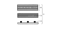

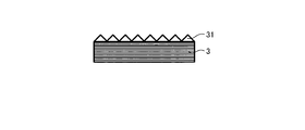

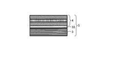
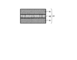
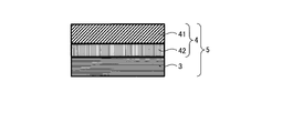
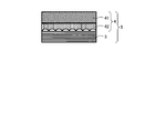
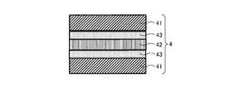

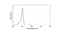
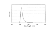
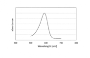
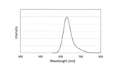
Classifications
-
- H—ELECTRICITY
- H01—ELECTRIC ELEMENTS
- H01L—SEMICONDUCTOR DEVICES NOT COVERED BY CLASS H10
- H01L33/00—Semiconductor devices having potential barriers specially adapted for light emission; Processes or apparatus specially adapted for the manufacture or treatment thereof or of parts thereof; Details thereof
- H01L33/48—Semiconductor devices having potential barriers specially adapted for light emission; Processes or apparatus specially adapted for the manufacture or treatment thereof or of parts thereof; Details thereof characterised by the semiconductor body packages
- H01L33/50—Wavelength conversion elements
- H01L33/501—Wavelength conversion elements characterised by the materials, e.g. binder
- H01L33/502—Wavelength conversion materials
-
- G—PHYSICS
- G02—OPTICS
- G02F—OPTICAL DEVICES OR ARRANGEMENTS FOR THE CONTROL OF LIGHT BY MODIFICATION OF THE OPTICAL PROPERTIES OF THE MEDIA OF THE ELEMENTS INVOLVED THEREIN; NON-LINEAR OPTICS; FREQUENCY-CHANGING OF LIGHT; OPTICAL LOGIC ELEMENTS; OPTICAL ANALOGUE/DIGITAL CONVERTERS
- G02F1/00—Devices or arrangements for the control of the intensity, colour, phase, polarisation or direction of light arriving from an independent light source, e.g. switching, gating or modulating; Non-linear optics
- G02F1/01—Devices or arrangements for the control of the intensity, colour, phase, polarisation or direction of light arriving from an independent light source, e.g. switching, gating or modulating; Non-linear optics for the control of the intensity, phase, polarisation or colour
- G02F1/13—Devices or arrangements for the control of the intensity, colour, phase, polarisation or direction of light arriving from an independent light source, e.g. switching, gating or modulating; Non-linear optics for the control of the intensity, phase, polarisation or colour based on liquid crystals, e.g. single liquid crystal display cells
- G02F1/133—Constructional arrangements; Operation of liquid crystal cells; Circuit arrangements
- G02F1/1333—Constructional arrangements; Manufacturing methods
- G02F1/1335—Structural association of cells with optical devices, e.g. polarisers or reflectors
- G02F1/1336—Illuminating devices
-
- F—MECHANICAL ENGINEERING; LIGHTING; HEATING; WEAPONS; BLASTING
- F21—LIGHTING
- F21S—NON-PORTABLE LIGHTING DEVICES; SYSTEMS THEREOF; VEHICLE LIGHTING DEVICES SPECIALLY ADAPTED FOR VEHICLE EXTERIORS
- F21S2/00—Systems of lighting devices, not provided for in main groups F21S4/00 - F21S10/00 or F21S19/00, e.g. of modular construction
-
- G—PHYSICS
- G02—OPTICS
- G02B—OPTICAL ELEMENTS, SYSTEMS OR APPARATUS
- G02B5/00—Optical elements other than lenses
- G02B5/20—Filters
-
- G—PHYSICS
- G02—OPTICS
- G02F—OPTICAL DEVICES OR ARRANGEMENTS FOR THE CONTROL OF LIGHT BY MODIFICATION OF THE OPTICAL PROPERTIES OF THE MEDIA OF THE ELEMENTS INVOLVED THEREIN; NON-LINEAR OPTICS; FREQUENCY-CHANGING OF LIGHT; OPTICAL LOGIC ELEMENTS; OPTICAL ANALOGUE/DIGITAL CONVERTERS
- G02F1/00—Devices or arrangements for the control of the intensity, colour, phase, polarisation or direction of light arriving from an independent light source, e.g. switching, gating or modulating; Non-linear optics
- G02F1/01—Devices or arrangements for the control of the intensity, colour, phase, polarisation or direction of light arriving from an independent light source, e.g. switching, gating or modulating; Non-linear optics for the control of the intensity, phase, polarisation or colour
- G02F1/13—Devices or arrangements for the control of the intensity, colour, phase, polarisation or direction of light arriving from an independent light source, e.g. switching, gating or modulating; Non-linear optics for the control of the intensity, phase, polarisation or colour based on liquid crystals, e.g. single liquid crystal display cells
- G02F1/133—Constructional arrangements; Operation of liquid crystal cells; Circuit arrangements
- G02F1/1333—Constructional arrangements; Manufacturing methods
- G02F1/1335—Structural association of cells with optical devices, e.g. polarisers or reflectors
- G02F1/1336—Illuminating devices
- G02F1/133602—Direct backlight
- G02F1/133605—Direct backlight including specially adapted reflectors
-
- G—PHYSICS
- G09—EDUCATION; CRYPTOGRAPHY; DISPLAY; ADVERTISING; SEALS
- G09F—DISPLAYING; ADVERTISING; SIGNS; LABELS OR NAME-PLATES; SEALS
- G09F9/00—Indicating arrangements for variable information in which the information is built-up on a support by selection or combination of individual elements
-
- H—ELECTRICITY
- H01—ELECTRIC ELEMENTS
- H01L—SEMICONDUCTOR DEVICES NOT COVERED BY CLASS H10
- H01L27/00—Devices consisting of a plurality of semiconductor or other solid-state components formed in or on a common substrate
- H01L27/14—Devices consisting of a plurality of semiconductor or other solid-state components formed in or on a common substrate including semiconductor components sensitive to infrared radiation, light, electromagnetic radiation of shorter wavelength or corpuscular radiation and specially adapted either for the conversion of the energy of such radiation into electrical energy or for the control of electrical energy by such radiation
- H01L27/144—Devices controlled by radiation
- H01L27/146—Imager structures
- H01L27/14601—Structural or functional details thereof
- H01L27/1462—Coatings
- H01L27/14621—Colour filter arrangements
-
- H—ELECTRICITY
- H01—ELECTRIC ELEMENTS
- H01L—SEMICONDUCTOR DEVICES NOT COVERED BY CLASS H10
- H01L33/00—Semiconductor devices having potential barriers specially adapted for light emission; Processes or apparatus specially adapted for the manufacture or treatment thereof or of parts thereof; Details thereof
- H01L33/48—Semiconductor devices having potential barriers specially adapted for light emission; Processes or apparatus specially adapted for the manufacture or treatment thereof or of parts thereof; Details thereof characterised by the semiconductor body packages
- H01L33/50—Wavelength conversion elements
- H01L33/505—Wavelength conversion elements characterised by the shape, e.g. plate or foil
-
- F—MECHANICAL ENGINEERING; LIGHTING; HEATING; WEAPONS; BLASTING
- F21—LIGHTING
- F21Y—INDEXING SCHEME ASSOCIATED WITH SUBCLASSES F21K, F21L, F21S and F21V, RELATING TO THE FORM OR THE KIND OF THE LIGHT SOURCES OR OF THE COLOUR OF THE LIGHT EMITTED
- F21Y2115/00—Light-generating elements of semiconductor light sources
- F21Y2115/10—Light-emitting diodes [LED]
-
- G—PHYSICS
- G02—OPTICS
- G02F—OPTICAL DEVICES OR ARRANGEMENTS FOR THE CONTROL OF LIGHT BY MODIFICATION OF THE OPTICAL PROPERTIES OF THE MEDIA OF THE ELEMENTS INVOLVED THEREIN; NON-LINEAR OPTICS; FREQUENCY-CHANGING OF LIGHT; OPTICAL LOGIC ELEMENTS; OPTICAL ANALOGUE/DIGITAL CONVERTERS
- G02F1/00—Devices or arrangements for the control of the intensity, colour, phase, polarisation or direction of light arriving from an independent light source, e.g. switching, gating or modulating; Non-linear optics
- G02F1/01—Devices or arrangements for the control of the intensity, colour, phase, polarisation or direction of light arriving from an independent light source, e.g. switching, gating or modulating; Non-linear optics for the control of the intensity, phase, polarisation or colour
- G02F1/13—Devices or arrangements for the control of the intensity, colour, phase, polarisation or direction of light arriving from an independent light source, e.g. switching, gating or modulating; Non-linear optics for the control of the intensity, phase, polarisation or colour based on liquid crystals, e.g. single liquid crystal display cells
- G02F1/133—Constructional arrangements; Operation of liquid crystal cells; Circuit arrangements
- G02F1/1333—Constructional arrangements; Manufacturing methods
- G02F1/1335—Structural association of cells with optical devices, e.g. polarisers or reflectors
- G02F1/1336—Illuminating devices
- G02F1/133602—Direct backlight
- G02F1/133603—Direct backlight with LEDs
-
- G—PHYSICS
- G02—OPTICS
- G02F—OPTICAL DEVICES OR ARRANGEMENTS FOR THE CONTROL OF LIGHT BY MODIFICATION OF THE OPTICAL PROPERTIES OF THE MEDIA OF THE ELEMENTS INVOLVED THEREIN; NON-LINEAR OPTICS; FREQUENCY-CHANGING OF LIGHT; OPTICAL LOGIC ELEMENTS; OPTICAL ANALOGUE/DIGITAL CONVERTERS
- G02F1/00—Devices or arrangements for the control of the intensity, colour, phase, polarisation or direction of light arriving from an independent light source, e.g. switching, gating or modulating; Non-linear optics
- G02F1/01—Devices or arrangements for the control of the intensity, colour, phase, polarisation or direction of light arriving from an independent light source, e.g. switching, gating or modulating; Non-linear optics for the control of the intensity, phase, polarisation or colour
- G02F1/13—Devices or arrangements for the control of the intensity, colour, phase, polarisation or direction of light arriving from an independent light source, e.g. switching, gating or modulating; Non-linear optics for the control of the intensity, phase, polarisation or colour based on liquid crystals, e.g. single liquid crystal display cells
- G02F1/133—Constructional arrangements; Operation of liquid crystal cells; Circuit arrangements
- G02F1/1333—Constructional arrangements; Manufacturing methods
- G02F1/1335—Structural association of cells with optical devices, e.g. polarisers or reflectors
- G02F1/1336—Illuminating devices
- G02F1/133614—Illuminating devices using photoluminescence, e.g. phosphors illuminated by UV or blue light
Definitions
- the present invention relates to a light source unit, a laminated member, and a display and an illumination device using them.
- Color conversion refers to conversion of light emitted from a light emitter into light having a longer wavelength, and represents, for example, conversion of blue light emission into green or red light emission.
- a composition having this color conversion function (hereinafter referred to as “color conversion composition”) is formed into a sheet and, for example, combined with a blue light source, three primary colors of blue, green, and red are extracted from the blue light source, that is, white light. Can be taken out.
- a white light source combining such a blue light source and a film having a color conversion function (hereinafter referred to as a “color conversion film”) is used as a backlight unit, and the backlight unit, a liquid crystal driving portion, and a color filter are combined. This makes it possible to produce a full color display.
- a white light source as it is, for example, it can be applied as a white light source such as LED lighting.
- An improvement in color reproducibility is an issue for liquid crystal displays that use color conversion methods.
- it is effective to increase the color purity of each color of blue, green, and red by narrowing the half width of each emission spectrum of blue, green, and red of the backlight unit.
- a technique using quantum dots made of inorganic semiconductor fine particles as a component of a color conversion film has been proposed (for example, see Patent Document 1).
- the technology using quantum dots certainly has a narrow half-value width of the emission spectrum of green and red and improves color reproducibility.
- quantum dots are weak against heat, moisture and oxygen in the air, and have sufficient durability. There wasn't.
- a technique using an organic light-emitting material as a component of a color conversion film instead of quantum dots has also been proposed.
- Examples of techniques using an organic light emitting material as a component of a color conversion film include those using a coumarin derivative (for example, see Patent Document 2), those using a rhodamine derivative (for example, see Patent Document 3), and a pyromethene derivative. The one used (see, for example, Patent Document 4) is known.
- the present invention has been made in view of the above problems, and its object is to provide a light source unit that achieves both improved color reproducibility and improved brightness in a color conversion film used for a display, illumination, or the like. is there.
- a light source unit includes a light source and an organic light-emitting material that converts incident light incident from the light source into light having a longer wavelength than the incident light. And a laminated film in which 11 or more layers of different thermoplastic resins are alternately laminated.
- the laminated film has a reflectance of 70% at a light incident angle of 60 °, which is converted to a longer wavelength than the incident light by the organic light emitting material. It is the laminated film which is the above, It is characterized by the above-mentioned.
- the laminated film has a reflectance of 20% or less of incident light incident on the laminated film from the light source at an incident angle of 10 °. It is characterized by being.
- the light source unit according to one embodiment of the present invention is characterized in that, in the above invention, the organic light emitting material contains a pyromethene derivative.
- the light source unit is characterized in that, in the above invention, the organic light-emitting material contains a compound represented by the general formula (1).
- X is C—R 7 or N.
- R 1 to R 9 may be the same or different and each represents hydrogen, an alkyl group, a cycloalkyl group, a heterocyclic group, an alkenyl group, a cycloalkenyl group, an alkynyl group, Hydroxyl group, thiol group, alkoxy group, alkylthio group, aryl ether group, aryl thioether group, aryl group, heteroaryl group, halogen, cyano group, aldehyde group, carbonyl group, carboxyl group, oxycarbonyl group, carbamoyl group, amino group, (Selected from nitro group, silyl group, siloxanyl group, boryl group, phosphine oxide group, and condensed ring and aliphatic ring formed between
- the light source unit is characterized in that, in this configuration, in the general formula (1), X is C—R 7 and R 7 is a group represented by the general formula (2).
- R is hydrogen, alkyl group, cycloalkyl group, heterocyclic group, alkenyl group, cycloalkenyl group, alkynyl group, hydroxyl group, thiol group, alkoxy group, alkylthio group, aryl ether group, aryl thioether group, aryl group, hetero It is selected from the group consisting of an aryl group, halogen, cyano group, aldehyde group, carbonyl group, carboxyl group, oxycarbonyl group, carbamoyl group, amino group, nitro group, silyl group, siloxanyl group, boryl group, and phosphine oxide group. Is an integer of 1 to 3. When k is 2 or more, r may be the same or different.
- R 1 , R 3 , R 4, and R 6 may be the same or different, and a substituted or unsubstituted phenyl group It is characterized by being.
- R 1 , R 3 , R 4 and R 6 may be the same or different, and a substituted or unsubstituted alkyl group It is characterized by being.
- the light source unit according to one embodiment of the present invention is characterized in that, in the above invention, the organic light emitting material emits light observed in a region where a peak wavelength is 500 nm or more and 580 nm or less.
- the light source unit is characterized in that, in the above invention, the organic light emitting material contains the following organic light emitting materials (a) and (b).
- the organic light emitting material contains the following organic light emitting materials (a) and (b).
- B Incident light or organic light-emitting material that is incident from a light source.
- the light source unit according to an aspect of the present invention is characterized in that, in this configuration, one or both of the organic light emitting materials (a) and (b) are compounds represented by the general formula (1). To do.
- the light source unit is characterized in that, in the above invention, the color conversion film is a laminate including at least the following (A) layer and (B) layer.
- the light source unit according to an aspect of the present invention is characterized in that, in the above invention, the light source unit includes a laminate including the color conversion film and the laminate film.
- the light source unit according to an aspect of the present invention is characterized in that, in the above invention, a light diffusion film is laminated on one or both surfaces of the color conversion film.
- the light source unit according to one aspect of the present invention is characterized in that, in the above invention, a prism sheet is provided on the light exit surface of the color conversion film.
- a functional layer is provided on a surface of the color conversion film or the laminated film, the refractive index of the laminated film is n1, and the refractive index of the color conversion film is The refractive index n3 of the functional layer is between n1 and n2 when the rate is n2.
- the light source unit according to one embodiment of the present invention is characterized in that, in the above invention, the surface of the laminated film or the color conversion film has an uneven shape.
- the light source unit according to one embodiment of the present invention is characterized in that the uneven shape is a lens shape, a substantially triangular shape, or a substantially semicircular shape.
- the light source unit according to one aspect of the present invention is the light source unit according to the above invention, wherein the laminated film or the color conversion film is incident on the laminated film or the color conversion film from the light source and an emission angle of the emitted light.
- the difference is 5 ° or more.
- the laminated film has a reflectance of 20% or more of light having a wavelength of 300 nm to 410 nm at an incident angle of 10 °, or 300 nm to 410 nm at an incident angle of 10 °.
- the following light absorptivity is 10% or more.
- the light source unit according to one embodiment of the present invention is characterized in that, in the above invention, the laminated film contains an ultraviolet absorber.
- the light source unit according to an aspect of the present invention is characterized in that, in the above invention, a resin layer containing an ultraviolet absorber is included on at least one surface of the laminated film.
- the light source unit is characterized in that, in the above invention, the ultraviolet absorber includes an ultraviolet absorber having a skeleton of anthraquinone, azomethine, indole, triazine, naphthalimide, or phthalocyanine. To do.
- the light source unit according to one aspect of the present invention is characterized in that, in the above invention, the laminated film is provided between the light source and the color conversion film.
- the light source unit according to one embodiment of the present invention is characterized in that, in the above invention, the light source is a light emitting diode having a maximum light emission in a range of 400 nm to 500 nm.
- the light source unit is a light emitting diode in which the light source has a maximum light emission in a range of 430 nm to 470 nm and a light emission wavelength region of 400 nm to 500 nm.
- the emission spectrum of the light source satisfies the formula (3). ( ⁇ is the emission intensity at the emission wavelength peak of the emission spectrum, and ⁇ is the emission intensity at the emission wavelength peak + 15 nm wavelength.)
- the light source unit according to one embodiment of the present invention is characterized in that, in this configuration, the light source has a maximum light emission in a range of 455 nm to 465 nm.
- a color conversion film including an organic light emitting material that converts incident light into light having a longer wavelength than the incident light and 11 or more layers of different thermoplastic resins are alternately laminated. And a laminated film.
- a display according to an aspect of the present invention includes the light source unit according to the above invention.
- An illumination device includes the light source unit according to the above invention.
- the light source unit and laminated member according to the present invention can realize low power consumption while being excellent in color reproducibility, and can be suitably used for a display and a lighting device.
- FIG. 1 is a schematic cross-sectional view showing an example of a light source unit according to an embodiment of the present invention.
- FIG. 2 is a schematic cross-sectional view showing an example of the laminated member according to the embodiment of the present invention.
- FIG. 3 is a schematic cross-sectional view showing an example of the uneven shape on the surface of the laminated film.
- FIG. 4 is a schematic cross-sectional view showing an example of the uneven shape on the surface of the laminated film.
- FIG. 5 is a schematic cross-sectional view showing an example of the laminated member according to the embodiment of the present invention.
- FIG. 6 is a schematic cross-sectional view showing an example of a color conversion film.
- FIG. 1 is a schematic cross-sectional view showing an example of a light source unit according to an embodiment of the present invention.
- FIG. 2 is a schematic cross-sectional view showing an example of the laminated member according to the embodiment of the present invention.
- FIG. 3 is a schematic cross-sectional view showing
- FIG. 7 is a schematic cross-sectional view showing an example of the laminated member according to the embodiment of the present invention.
- FIG. 8 is a schematic cross-sectional view showing an example of the laminated member according to the embodiment of the present invention.
- FIG. 9 is a schematic cross-sectional view showing an example of the laminated member according to the embodiment of the present invention.
- FIG. 10 is a schematic cross-sectional view showing another example of the light source unit according to the embodiment of the present invention.
- FIG. 11 is a diagram illustrating the absorption spectrum of the compound of Synthesis Example 1 in the examples of the present invention.
- FIG. 12 is a diagram illustrating an emission spectrum of the compound of Synthesis Example 1 in the example of the present invention.
- FIG. 13 is a diagram illustrating an absorption spectrum of the compound of Synthesis Example 2 in the example of the present invention.
- FIG. 14 is a diagram illustrating an emission spectrum of the compound of Synthesis Example 2 in the example of the present invention.
- FIG. 1 is a schematic cross-sectional view showing an example of a light source unit according to an embodiment.
- the light source unit 1 of the present invention needs to include a light source 2, a laminated film 3, and a color conversion film 4.
- FIG. 2 is a schematic cross-sectional view showing an example of the laminated member according to the embodiment.
- the laminated member 5 of the present invention needs to include a laminated film 3 and a color conversion film 4.
- the color conversion film used in the present invention contains at least one organic light emitting material and a binder resin, and functions as a color conversion layer that converts incident light into light having a longer wavelength than the incident light.
- the color conversion film used in the present invention is a continuous layer.
- the continuous layer refers to a layer that is not divided.
- a layer containing an organic light emitting material and a binder resin is patterned and present in the same plane, it is a divided layer and therefore does not correspond to the continuous layer referred to in the present invention.
- a cut or a dent partially, but it is a structure that is integrated as a whole, it corresponds to a continuous layer.
- the film thickness of the color conversion film is not particularly limited, but is preferably 10 to 1000 ⁇ m from the viewpoint of film toughness and ease of forming. On the other hand, from the viewpoint of improving heat resistance, the film thickness of the color conversion film is preferably 200 ⁇ m or less, more preferably 100 ⁇ m or less, and even more preferably 50 ⁇ m or less.
- the film thickness of the color conversion film in the present invention is a film thickness (average film thickness) measured based on the method A of measuring thickness by mechanical scanning in JIS K7130 (1999) plastic-film and sheet-thickness measuring method. ). The same applies to the following description.
- the color conversion film used for the laminated member and the light source unit according to the embodiment of the present invention includes an organic light emitting material.
- the light-emitting material in the present invention refers to a material that emits light having a wavelength different from that of light when irradiated with some light.
- the organic light emitting material is an organic light emitting material.
- the light-emitting material is preferably a material exhibiting light emission characteristics with a high light emission quantum yield.
- the luminescent material include known luminescent materials such as inorganic phosphors, fluorescent pigments, fluorescent dyes, and quantum dots. From the viewpoint of uniformity of dispersion, reduction of use amount, and reduction of environmental load, organic luminescent materials. Is preferred.
- organic light emitting material examples include those shown below.
- Compounds having a condensed aryl ring such as naphthalene, anthracene, phenanthrene, pyrene, chrysene, naphthacene, triphenylene, perylene, fluoranthene, fluorene, indene and derivatives thereof; Furan, pyrrole, thiophene, silole, 9-silafluorene, 9,9'-spirobisilafluorene, benzothiophene, benzofuran, indole, dibenzothiophene, dibenzofuran, imidazopyridine, phenanthroline, pyridine, pyrazine, naphthyridine, quinoxaline, pyrrolopyridine
- a compound having a heteroaryl ring such as Borane derivatives; 1,4-distyrylbenzene, 4,4′-bis (2- (4-diphenyla
- the organic light emitting material may be a fluorescent light emitting material or a phosphorescent light emitting material, but a fluorescent light emitting material is preferred in order to achieve high color purity.
- a compound having a condensed aryl ring and a derivative thereof are preferable because of high thermal stability and light stability.
- a compound having a coordination bond is preferable from the viewpoint of solubility and diversity of molecular structure.
- a compound containing boron such as a boron fluoride complex is also preferable in that the half width is small and highly efficient light emission is possible.
- a pyromethene derivative is preferable because it gives a high fluorescence quantum yield and has good durability. More preferably, it is a compound represented by the general formula (1), that is, a pyromethene compound.
- R 1 to R 9 may be the same as or different from each other, and may be hydrogen, alkyl group, cycloalkyl group, heterocyclic group, alkenyl group, cycloalkenyl group, alkynyl group, hydroxyl group, thiol group, alkoxy group, alkylthio group, aryl Ether group, arylthioether group, aryl group, heteroaryl group, halogen, cyano group, aldehyde group, carbonyl group, carboxyl group, oxycarbonyl group, carbamoyl group, amino group, nitro group, silyl group, siloxanyl group, boryl group, It is selected from a condensed ring and an aliphatic ring formed between a phosphine oxide group and an adjacent substituent.
- hydrogen may be deuterium.
- a substituted or unsubstituted aryl group having 6 to 40 carbon atoms is an aryl group having 6 to 40 carbon atoms in total including the carbon number contained in the substituent substituted on the aryl group. It is. The same applies to other substituents that define the number of carbon atoms.
- the substituents in the case of substitution include alkyl groups, cycloalkyl groups, heterocyclic groups, alkenyl groups, cycloalkenyl groups, alkynyl groups, hydroxyl groups, thiol groups, alkoxy groups, alkylthio groups.
- Aryl ether group, aryl thioether group, aryl group, heteroaryl group, halogen, cyano group, aldehyde group, carbonyl group, carboxyl group, oxycarbonyl group, carbamoyl group, amino group, nitro group, silyl group, siloxanyl group, boryl Group and a phosphine oxide group are preferable, and specific substituents that are preferable in the description of each substituent are preferable. Moreover, these substituents may be further substituted with the above-mentioned substituents.
- unsubstituted means that a hydrogen atom or a deuterium atom is substituted.
- the alkyl group is, for example, a saturated aliphatic hydrocarbon such as methyl group, ethyl group, n-propyl group, isopropyl group, n-butyl group, sec-butyl group, tert-butyl group, etc.
- the additional substituent when it is substituted and examples thereof include an alkyl group, a halogen, an aryl group, a heteroaryl group, and the like, and this point is common to the following description.
- the number of carbon atoms of the alkyl group is not particularly limited, but is preferably 1 or more and 20 or less, more preferably 1 or more and 8 or less, from the viewpoint of availability and cost.
- the cycloalkyl group refers to, for example, a saturated alicyclic hydrocarbon group such as a cyclopropyl group, a cyclohexyl group, a norbornyl group, an adamantyl group, which may or may not have a substituent.
- carbon number of an alkyl group part is not specifically limited, Preferably it is the range of 3 or more and 20 or less.
- the heterocyclic group refers to an aliphatic ring having atoms other than carbon, such as a pyran ring, a piperidine ring, and a cyclic amide, in the ring, which may or may not have a substituent. .
- carbon number of a heterocyclic group is not specifically limited, Preferably it is the range of 2-20.
- alkenyl group refers to an unsaturated aliphatic hydrocarbon group containing a double bond such as a vinyl group, an allyl group, or a butadienyl group, which may or may not have a substituent.
- carbon number of an alkenyl group is not specifically limited, Preferably it is the range of 2-20.
- the cycloalkenyl group refers to an unsaturated alicyclic hydrocarbon group containing a double bond such as a cyclopentenyl group, a cyclopentadienyl group, or a cyclohexenyl group, which may have a substituent. You don't have to.
- the alkynyl group indicates, for example, an unsaturated aliphatic hydrocarbon group containing a triple bond such as an ethynyl group, which may or may not have a substituent.
- carbon number of an alkynyl group is not specifically limited, Preferably it is the range of 2-20.
- the alkoxy group refers to, for example, a functional group having an aliphatic hydrocarbon group bonded through an ether bond such as a methoxy group, an ethoxy group, or a propoxy group, and the aliphatic hydrocarbon group may have a substituent. It may not have.
- the number of carbon atoms of the alkoxy group is not particularly limited, but is preferably in the range of 1 or more and 20 or less.
- the alkylthio group is a group in which an oxygen atom of an ether bond of an alkoxy group is substituted with a sulfur atom.
- the hydrocarbon group of the alkylthio group may or may not have a substituent.
- carbon number of an alkylthio group is not specifically limited, Preferably it is the range of 1 or more and 20 or less.
- An aryl ether group refers to a functional group to which an aromatic hydrocarbon group is bonded via an ether bond, such as a phenoxy group, and the aromatic hydrocarbon group may or may not have a substituent. Good.
- the number of carbon atoms of the aryl ether group is not particularly limited, but is preferably in the range of 6 or more and 40 or less.
- the aryl thioether group is a group in which an oxygen atom of an ether bond of an aryl ether group is substituted with a sulfur atom.
- the aromatic hydrocarbon group in the aryl thioether group may or may not have a substituent.
- the number of carbon atoms of the aryl ether group is not particularly limited, but is preferably in the range of 6 or more and 40 or less.
- the aryl group is, for example, phenyl group, biphenyl group, terphenyl group, naphthyl group, fluorenyl group, benzofluorenyl group, dibenzofluorenyl group, phenanthryl group, anthracenyl group, benzophenanthryl group, benzoanthracene group.
- An aromatic hydrocarbon group such as a nyl group, a chrycenyl group, a pyrenyl group, a fluoranthenyl group, a triphenylenyl group, a benzofluoranthenyl group, a dibenzoanthracenyl group, a perylenyl group, or a helicenyl group.
- a phenyl group, a biphenyl group, a terphenyl group, a naphthyl group, a fluorenyl group, a phenanthryl group, an anthracenyl group, a pyrenyl group, a fluoranthenyl group, and a triphenylenyl group are preferable.
- the aryl group may or may not have a substituent. Although carbon number of an aryl group is not specifically limited, Preferably it is 6 or more and 40 or less, More preferably, it is the range of 6 or more and 30 or less.
- the aryl group is preferably a phenyl group, a biphenyl group, a terphenyl group, a naphthyl group, a fluorenyl group, a phenanthryl group or an anthracenyl group, and a phenyl group or a biphenyl group More preferred are a terphenyl group and a naphthyl group. More preferred are a phenyl group, a biphenyl group, and a terphenyl group, and a phenyl group is particularly preferred.
- the aryl group is preferably a phenyl group, a biphenyl group, a terphenyl group, a naphthyl group, a fluorenyl group, a phenanthryl group, or an anthracenyl group.
- a phenyl group and a naphthyl group are more preferable. Particularly preferred is a phenyl group.
- Heteroaryl group is, for example, pyridyl group, furanyl group, thienyl group, quinolinyl group, isoquinolinyl group, pyrazinyl group, pyrimidyl group, pyridazinyl group, triazinyl group, naphthyridinyl group, cinnolinyl group, phthalazinyl group, quinoxalinyl group, quinazolinyl group, Benzofuranyl group, benzothienyl group, indolyl group, dibenzofuranyl group, dibenzothienyl group, carbazolyl group, benzocarbazolyl group, carbolinyl group, indolocarbazolyl group, benzofurocarbazolyl group, benzothienocarbazolyl Group, dihydroindenocarbazolyl group, benzoquinolinyl group, acridinyl group, dibenzoacridinyl
- the naphthyridinyl group is any of 1,5-naphthyridinyl group, 1,6-naphthyridinyl group, 1,7-naphthyridinyl group, 1,8-naphthyridinyl group, 2,6-naphthyridinyl group, and 2,7-naphthyridinyl group.
- the heteroaryl group may or may not have a substituent.
- carbon number of a heteroaryl group is not specifically limited, Preferably it is 2 or more and 40 or less, More preferably, it is the range of 2 or more and 30 or less.
- heteroaryl group examples include pyridyl group, furanyl group, thienyl group, quinolinyl group, pyrimidyl group, triazinyl group, benzofuranyl group, benzothienyl group, indolyl group , Dibenzofuranyl group, dibenzothienyl group, carbazolyl group, benzoimidazolyl group, imidazopyridyl group, benzoxazolyl group, benzothiazolyl group, phenanthrolinyl group are preferable, pyridyl group, furanyl group, thienyl group, quinolinyl group are more preferable. Particularly preferred is a pyridyl group.
- the heteroaryl group includes pyridyl, furanyl, thienyl, quinolinyl, pyrimidyl, triazinyl, benzofuranyl, benzothienyl, indolyl, dibenzo A furanyl group, a dibenzothienyl group, a carbazolyl group, a benzimidazolyl group, an imidazopyridyl group, a benzoxazolyl group, a benzothiazolyl group, and a phenanthrolinyl group are preferable, and a pyridyl group, a furanyl group, a thienyl group, and a quinolinyl group are more preferable. Particularly preferred is a pyridyl group.
- Halogen refers to an atom selected from fluorine, chlorine, bromine and iodine.
- the carbonyl group, carboxyl group, oxycarbonyl group and carbamoyl group may or may not have a substituent.
- substituents include an alkyl group, a cycloalkyl group, an aryl group, and a heteroaryl group, and these substituents may be further substituted.
- An amino group is a substituted or unsubstituted amino group.
- substituent in the case of substitution include an aryl group, a heteroaryl group, a linear alkyl group, and a branched alkyl group.
- aryl group and heteroaryl group a phenyl group, a naphthyl group, a pyridyl group, and a quinolinyl group are preferable. These substituents may be further substituted.
- carbon number is not specifically limited, Preferably it is 2 or more and 50 or less, More preferably, it is 6 or more and 40 or less, Especially preferably, it is the range of 6 or more and 30 or less.
- silyl groups include trimethylsilyl groups, triethylsilyl groups, tert-butyldimethylsilyl groups, propyldimethylsilyl groups, vinyldimethylsilyl groups, and other alkylsilyl groups, phenyldimethylsilyl groups, tert-butyldiphenylsilyl groups, An arylsilyl group such as a phenylsilyl group or a trinaphthylsilyl group is shown. Substituents on silicon may be further substituted. Although carbon number of a silyl group is not specifically limited, Preferably it is the range of 1 or more and 30 or less.
- the siloxanyl group refers to a silicon compound group via an ether bond such as a trimethylsiloxanyl group. Substituents on silicon may be further substituted.
- the boryl group is a substituted or unsubstituted boryl group.
- substituent in the case of substitution include an aryl group, a heteroaryl group, a linear alkyl group, a branched alkyl group, an aryl ether group, an alkoxy group, and a hydroxyl group, and among them, an aryl group and an aryl ether group are preferable.
- the phosphine oxide group is a group represented by —P ( ⁇ O) R 10 R 11 .
- R 10 R 11 is selected from the same group as R 1 to R 9 .
- the condensed ring formed between adjacent substituents means that any adjacent two substituents (for example, R 1 and R 2 in the general formula (1)) are bonded to each other to form a conjugated or non-conjugated cyclic skeleton. It means forming.
- Such a constituent element of the condensed ring may contain an element selected from nitrogen, oxygen, sulfur, phosphorus and silicon in addition to carbon. Further, these condensed rings may be further condensed with another ring.
- the compound represented by the general formula (1) exhibits a high fluorescence quantum yield and has a small peak half-value width of the emission spectrum, it is possible to achieve both efficient color conversion and high color purity. .
- the compound represented by the general formula (1) introduces an appropriate substituent at an appropriate position, so that various properties such as light emission efficiency, color purity, thermal stability, light stability and dispersibility can be obtained. And physical properties can be adjusted.
- R 1 , R 3 , R 4 and R 6 are all hydrogen
- at least one of R 1 , R 3 , R 4 and R 6 is a substituted or unsubstituted alkyl group or a substituted or unsubstituted group.
- R 1 , R 3 , R 4 and R 6 is a substituted or unsubstituted alkyl group or a substituted or unsubstituted group.
- R 1 , R 3 , R 4 and R 6 is a substituted or unsubstituted alkyl group or a substituted or unsubstituted group.
- an aryl group a substituted or unsubstituted heteroaryl group, better thermal stability and light stability are exhibited.
- R 1 , R 3 , R 4 and R 6 are a substituted or unsubstituted alkyl group
- examples of the alkyl group include a methyl group, an ethyl group, an n-propyl group, an isopropyl group, an n-butyl group, Alkyl groups having 1 to 6 carbon atoms such as sec-butyl group, tert-butyl group, pentyl group and hexyl group are preferred.
- the alkyl group is preferably a methyl group, an ethyl group, an n-propyl group, an isopropyl group, an n-butyl group, a sec-butyl group, or a tert-butyl group from the viewpoint of excellent thermal stability. Further, from the viewpoint of preventing concentration quenching and improving the fluorescence quantum yield, this alkyl group is more preferably a sterically bulky tert-butyl group. From the viewpoint of ease of synthesis and availability of raw materials, a methyl group is also preferably used as the alkyl group.
- the aryl group is preferably a phenyl group, a biphenyl group, a terphenyl group or a naphthyl group, more preferably A phenyl group and a biphenyl group. Particularly preferred is a phenyl group.
- the heteroaryl group is preferably a pyridyl group, a quinolinyl group or a thienyl group, more preferably a pyridyl group or a quinolinyl group. preferable. Particularly preferred is a pyridyl group.
- R 1 , R 3 , R 4 and R 6 may all be the same or different, and a substituted or unsubstituted alkyl group is preferable because of good solubility in a binder resin and a solvent.
- the alkyl group is preferably a methyl group from the viewpoints of ease of synthesis and availability of raw materials.
- R 1 , R 3 , R 4 and R 6 may all be the same or different and when they are substituted or unsubstituted aryl groups or substituted or unsubstituted heteroaryl groups, better thermal stability and This is preferable because it shows light stability.
- R 1 , R 3 , R 4 and R 6 may all be the same or different, and are more preferably substituted or unsubstituted aryl groups.
- R 1 , R 3 , R 4 and R 6 may all be the same or different and are substituted or unsubstituted aryl groups, for example, R 1 ⁇ R 4 , R 3 ⁇ R 6 .
- R 1 ⁇ R 4 , R 3 ⁇ R 6 It is preferable to introduce a plurality of types of substituents such as R 1 ⁇ R 3 or R 4 ⁇ R 6 .
- ⁇ indicates a group having a different structure.
- R 1 ⁇ R 4 indicates that R 1 and R 4 are groups having different structures.
- R 1 ⁇ R 3 or R 4 ⁇ R 6 is preferable from the viewpoint of improving the light emission efficiency and the color purity in a balanced manner.
- one or more aryl groups that affect the color purity are introduced into the pyrrole rings on both sides, and the aryl that affects the luminous efficiency at other positions. Since groups can be introduced, both of these properties can be maximized.
- an aryl group substituted with an electron donating group is preferable.
- the electron donating group include an alkyl group and an alkoxy group.
- an alkyl group having 1 to 8 carbon atoms or an alkoxy group having 1 to 8 carbon atoms is preferable, and a methyl group, an ethyl group, a tert-butyl group, or a methoxy group is more preferable. From the viewpoint of dispersibility, a tert-butyl group and a methoxy group are particularly preferable.
- the substitution position of the substituent is not particularly limited, it is necessary to suppress the twisting of the bond in order to increase the light stability of the compound represented by the general formula (1). It is preferable to bond to the position or para position.
- an aryl group having a bulky substituent such as a tert-butyl group, an adamantyl group or a methoxy group is preferable.
- R 1 , R 3 , R 4 and R 6 may be the same or different, and when they are substituted or unsubstituted aryl groups, R 1 , R 3 , R 4 and R 6 are the same or different. It may be a substituted or unsubstituted phenyl group.
- R 1 , R 3 , R 4 and R 6 are more preferably selected from the following Ar-1 to Ar-6, respectively.
- preferred combinations of R 1 , R 3 , R 4 and R 6 include those shown in Table 1-1 to Table 1-11, but are not limited thereto.
- R 2 and R 5 are preferably any one of hydrogen, an alkyl group, a carbonyl group, an oxycarbonyl group, and an aryl group.
- hydrogen or an alkyl group is preferable from the viewpoint of thermal stability, and hydrogen is more preferable from the viewpoint of easily obtaining a narrow half width in the emission spectrum.
- R 8 and R 9 are preferably an alkyl group, aryl group, heteroaryl group, fluorine, fluorine-containing alkyl group, fluorine-containing heteroaryl group or fluorine-containing aryl group.
- R 8 and R 9 are more preferably fluorine or a fluorine-containing aryl group because they are stable against a light source and a higher fluorescence quantum yield is obtained. Further, R 8 and R 9 are more preferably fluorine for ease of synthesis.
- the fluorine-containing aryl group is an aryl group containing fluorine, and examples thereof include a fluorophenyl group, a trifluoromethylphenyl group, and a pentafluorophenyl group.
- the fluorine-containing heteroaryl group is a heteroaryl group containing fluorine, and examples thereof include a fluoropyridyl group, a trifluoromethylpyridyl group, and a trifluoropyridyl group.
- the fluorine-containing alkyl group is an alkyl group containing fluorine, and examples thereof include a trifluoromethyl group and a pentafluoroethyl group.
- X is preferably C—R 7 (C: carbon) from the viewpoint of light stability.
- the substituent R 7 greatly affects the durability of the compound represented by the general formula (1), that is, the decrease in the emission intensity of this compound over time. Specifically, when R 7 is hydrogen, the reactivity of this hydrogen is high, and this part easily reacts with moisture and oxygen in the air. This causes decomposition of the compound represented by the general formula (1). In addition, when R 7 is a substituent having a large degree of freedom of movement of a molecular chain such as an alkyl group, for example, the reactivity is certainly lowered, but the compounds aggregate with time in the composition. In particular, the emission intensity is reduced due to concentration quenching.
- R 7 is preferably a group that is rigid and has a low degree of freedom of movement and is unlikely to cause aggregation. Specifically, R 7 is a substituted or unsubstituted aryl group, or a substituted or unsubstituted heteroaryl group. It is preferable that
- X is C—R 7 and R 7 is a substituted or unsubstituted aryl group.
- aryl group a phenyl group, a biphenyl group, a terphenyl group, a naphthyl group, a fluorenyl group, a phenanthryl group, and an anthracenyl group are preferable from the viewpoint of not impairing the emission wavelength.
- R 7 is preferably a substituted or unsubstituted phenyl group, a substituted or unsubstituted biphenyl group, a substituted or unsubstituted terphenyl group, or a substituted or unsubstituted naphthyl group.
- a phenyl group, a substituted or unsubstituted biphenyl group, and a substituted or unsubstituted terphenyl group are more preferable. Particularly preferred is a substituted or unsubstituted phenyl group.
- R 7 is preferably a moderately bulky substituent.
- R 7 has a certain amount of bulkiness, aggregation of molecules can be prevented. As a result, the luminous efficiency and durability of the compound represented by the general formula (1) are further improved.
- a more preferred example of such a bulky substituent includes the structure of R 7 represented by the following general formula (2).
- r is hydrogen, alkyl group, cycloalkyl group, heterocyclic group, alkenyl group, cycloalkenyl group, alkynyl group, hydroxyl group, thiol group, alkoxy group, alkylthio group, aryl ether group, aryl thioether Group, aryl group, heteroaryl group, halogen, cyano group, aldehyde group, carbonyl group, carboxyl group, oxycarbonyl group, carbamoyl group, amino group, nitro group, silyl group, siloxanyl group, boryl group, phosphine oxide group Selected from the group.
- k is an integer of 1 to 3. When k is 2 or more, r may be the same or different.
- r is preferably a substituted or unsubstituted aryl group.
- aryl groups a phenyl group and a naphthyl group are particularly preferable examples.
- k in the general formula (2) is preferably 1 or 2, and among them, k is more preferably 2 from the viewpoint of further preventing aggregation of molecules.
- k is 2 or more, it is preferable that at least one of r is substituted with an alkyl group.
- the alkyl group in this case, a methyl group, an ethyl group, and a tert-butyl group are particularly preferable from the viewpoint of thermal stability.
- r is preferably a substituted or unsubstituted alkyl group, a substituted or unsubstituted alkoxy group or a halogen, More preferred are a methyl group, an ethyl group, a tert-butyl group, and a methoxy group. From the viewpoint of dispersibility, a tert-butyl group and a methoxy group are particularly preferable. When r is a tert-butyl group or a methoxy group, it is more effective for preventing quenching due to aggregation between molecules.
- R 1 to R 7 is an electron withdrawing group.
- R 1 to R 6 is an electron withdrawing group
- R 7 is an electron withdrawing group
- one is an electron withdrawing group
- R 7 is an electron withdrawing group.
- the electron-withdrawing group is also called an electron-accepting group, and is an atomic group that attracts electrons from a substituted atomic group by an induced effect or a resonance effect in organic electron theory.
- Examples of the electron withdrawing group include those having a positive value as the Hammett's rule substituent constant ( ⁇ p (para)).
- the Hammett's rule substituent constant ( ⁇ p (para)) can be cited from the Chemical Handbook, Basic Revision 5 (II-380).
- a phenyl group also has an example which takes a positive value as mentioned above, in this invention, a phenyl group is not contained in an electron withdrawing group.
- electron withdrawing groups include, for example, -F ( ⁇ p: +0.06), -Cl ( ⁇ p: +0.23), -Br ( ⁇ p: +0.23), -I ( ⁇ p: +0.18), -CO 2 R 12 ( ⁇ p: when R 12 is an ethyl group +0.45), -CONH 2 ( ⁇ p: +0.38), -COR 12 ( ⁇ p: when R 12 is a methyl group +0.49),- Examples include CF 3 ( ⁇ p: +0.50), —SO 2 R 12 ( ⁇ p: +0.69 when R 12 is a methyl group), —NO 2 ( ⁇ p: +0.81), and the like.
- R 12 each independently represents a hydrogen atom, a substituted or unsubstituted aromatic hydrocarbon group having 6 to 30 ring carbon atoms, a substituted or unsubstituted heterocyclic group having 5 to 30 ring atoms, substituted or unsubstituted
- a substituted alkyl group having 1 to 30 carbon atoms and a substituted or unsubstituted cycloalkyl group having 1 to 30 carbon atoms are represented. Specific examples of these groups include the same examples as described above.
- Preferred electron withdrawing groups include fluorine, fluorine-containing aryl groups, fluorine-containing heteroaryl groups, fluorine-containing alkyl groups, substituted or unsubstituted acyl groups, substituted or unsubstituted ester groups, substituted or unsubstituted amide groups, Examples thereof include a substituted or unsubstituted sulfonyl group or a cyano group. This is because they are difficult to decompose chemically.
- More preferred electron withdrawing groups include a fluorine-containing alkyl group, a substituted or unsubstituted acyl group, a substituted or unsubstituted ester group, or a cyano group. This is because these lead to the effect of preventing concentration quenching and improving the emission quantum yield. Particularly preferred electron withdrawing groups are substituted or unsubstituted ester groups.
- R 1 , R 3 , R 4 and R 6 may all be the same or different, and each may be a substituted or unsubstituted alkyl group.
- X is C—R 7 and R 7 is a group represented by the general formula (2).
- R 7 is particularly preferably a group represented by the general formula (2) in which r is included as a substituted or unsubstituted phenyl group.
- R 1 , R 3 , R 4 and R 6 may all be the same or different, and the above-mentioned Ar— And a case where X is C—R 7 and R 7 is a group represented by the general formula (2).
- R 7 is more preferably a group represented by the general formula (2) in which r is a tert-butyl group or a methoxy group, and represented by the general formula (2) in which r is a methoxy group. It is particularly preferred that
- the compound represented by the general formula (1) can be prepared, for example, by the method described in JP-T-8-509471 and JP-A-2000-208262. That is, the target pyromethene metal complex is obtained by reacting the pyromethene compound and the metal salt in the presence of a base.
- a method of generating a carbon-carbon bond by using a coupling reaction between a halogenated derivative and a boronic acid or a boronic acid esterified derivative can be mentioned.
- the present invention is not limited to this.
- introducing an amino group or a carbazolyl group for example, there is a method of generating a carbon-nitrogen bond by using a coupling reaction between a halogenated derivative and an amine or a carbazole derivative under a metal catalyst such as palladium.
- the present invention is not limited to this.
- the color conversion film used in the present invention can appropriately contain other compounds as necessary in addition to the compound represented by the general formula (1).
- an assist dopant such as rubrene may be contained.
- a desired organic light emitting material for example, an organic light emitting material such as a coumarin dye or a rhodamine dye may be added. it can.
- known light-emitting materials such as inorganic phosphors, fluorescent pigments, fluorescent dyes, and quantum dots can be added in combination.
- organic light emitting materials other than the compound represented by the general formula (1) are shown below, but the present invention is not particularly limited to these.
- the color conversion film used in the present invention is an organic light-emitting material that exhibits light emission observed in a region having a peak wavelength of 500 nm or more and 580 nm or less by using light from a light source that emits light in a wavelength range of 400 nm or more and 500 nm or less.
- organic light-emitting material (a) light emission observed in a region where the peak wavelength is 500 nm or more and 580 nm or less is referred to as “green light emission”.
- the light from a light source is more likely to cause material decomposition as its energy increases.
- the color conversion film used in the present invention preferably contains the following organic light emitting material (a) and organic light emitting material (b).
- the organic light emitting material (a) is a light emitting material that emits light having a peak wavelength of 500 nm or more and 580 nm or less by using a light source that emits light having a wavelength of 400 nm or more and 500 nm or less.
- the organic light emitting material (b) has a peak wavelength of 580 nm when excited by either or both of light from a light source emitting light having a wavelength in the range of 400 nm or more and 500 nm or less and light emission from the organic light emitting material (a).
- the light-emitting material exhibits light emission observed in a region of 750 nm or less.
- light emission observed in a region having a peak wavelength of 580 nm or more and 750 nm or less is referred to as “red light emission”.
- a part of the light source in the wavelength range of 400 nm or more and 500 nm or less is partially transmitted through the color conversion film used in the present invention. Therefore, when a blue LED having a sharp emission peak is used, each color of blue, green, and red is sharp. An emission spectrum of a shape is shown, and white light with good color purity can be obtained. As a result, particularly in a display, a larger color gamut with more vivid colors can be efficiently produced. In addition, in lighting applications, the light emission characteristics of the green region and the red region are particularly improved compared to white LEDs that are a combination of blue LEDs and yellow phosphors, which are currently mainstream, so that the preferred white color with improved color rendering is achieved. A light source can be obtained.
- the overlap of emission spectra of blue, green and red colors is small.
- the lower limit value of the peak wavelength of the organic light emitting material (a) is more preferably 510 nm or more, further preferably 515 nm or more, and particularly preferably 520 nm or more.
- the upper limit value of the peak wavelength of the organic light emitting material (a) is more preferably 550 nm or less, further preferably 540 nm or less, and particularly preferably 530 nm or less.
- the lower limit value of the peak wavelength of the organic light emitting material (b) is more preferably 620 nm or more, further preferably 630 nm or more, and particularly preferably 635 nm or more.
- the upper limit of the peak wavelength of red light may be 750 nm or less in the vicinity of the upper limit of the visible range. However, when it is 700 nm or less, the visibility is increased, which is more preferable.
- the upper limit of the peak wavelength of the organic light emitting material (b) is more preferably 680 nm or less, and particularly preferably 660 nm or less.
- the peak wavelength of green light is preferably observed in a region of 500 nm or more and 580 nm or less, and is preferably 510 nm or more and 550 nm or less. More preferably, it is 515 nm or more and 540 nm or less, more preferably 520 nm or more and 530 nm or less.
- the peak wavelength of red light is preferably observed in the region of 580 nm or more and 750 nm or less, more preferably 620 nm or more and 700 nm or less, further preferably 630 nm or more and 680 nm or less, 635 nm or more, Particularly preferably, it is 660 nm or less.
- the half-value widths of the emission spectra of blue, green and red are small.
- the half-value width of the emission spectrum of green light is preferably 50 nm or less, more preferably 40 nm or less, still more preferably 35 nm or less, and particularly preferably 30 nm or less.
- the half-value width of the emission spectrum of red light is preferably 80 nm or less, more preferably 70 nm or less, still more preferably 60 nm or less, and particularly preferably 50 nm or less.
- the shape of the emission spectrum is not particularly limited, but it is preferably a single peak because excitation energy can be used efficiently and color purity is increased.
- the single peak indicates a state where there is no peak having an intensity of 5% or more of the strongest peak in a certain wavelength region.
- organic light-emitting material (a) examples include coumarin derivatives such as coumarin 6, coumarin 7, coumarin 153, cyanine derivatives such as indocyanine green, fluorescein derivatives such as fluorescein, fluorescein isothiocyanate, carboxyfluorescein diacetate, and phthalocyanines such as phthalocyanine green.
- coumarin derivatives such as coumarin 6, coumarin 7, coumarin 153
- cyanine derivatives such as indocyanine green
- fluorescein derivatives such as fluorescein, fluorescein isothiocyanate, carboxyfluorescein diacetate
- phthalocyanines such as phthalocyanine green.
- perylene derivatives such as diisobutyl-4,10-dicyanoperylene-3,9-dicarboxylate
- pyromethene derivatives stilbene derivatives, oxazine derivatives, naphthalimide derivatives, pyrazine derivatives, benzimidazole derivatives, benzoxazole derivatives, benzo Compounds having condensed aryl rings such as thiazole derivatives, imidazopyridine derivatives, azole derivatives, anthracene and their derivatives, aromatic amine derivatives
- the organic metal complex compound and the like is not particularly limited thereto.
- pyromethene derivatives are particularly suitable because they give high fluorescence quantum yield and good durability.
- the compound represented by the general formula (1) is preferable because it emits light with high color purity.
- organic light emitting material (b) examples include cyanine derivatives such as 4-dicyanomethylene-2-methyl-6- (p-dimethylaminostyryl) -4H-pyran, rhodamine B, rhodamine 6G, rhodamine 101, sulforhodamine 101 and the like.
- Rhodamine derivatives pyridine derivatives such as 1-ethyl-2- (4- (p-dimethylaminophenyl) -1,3-butadienyl) -pyridinium-perchlorate, N, N′-bis (2,6-diisopropylphenyl) ) -1,6,7,12-tetraphenoxyperylene-3,4: 9,10-bisdicarbomide and other perylene derivatives, porphyrin derivatives, pyromethene derivatives, oxazine derivatives, pyrazine derivatives, naphthacene and dibenzodiindene Compounds having condensed aryl rings such as noperylene and their derivatives, organic Metal complex compounds, and the like as preferred.
- pyridine derivatives such as 1-ethyl-2- (4- (p-dimethylaminophenyl) -1,3-butadienyl) -pyridinium-perchlor
- the organic light emitting material (b) is not particularly limited thereto.
- pyromethene derivatives are particularly suitable because they give high fluorescence quantum yield and good durability.
- the compound represented by the general formula (1) is preferable because it emits light with high color purity.
- the content of the (A) organic light emitting material component in the color conversion film used in the present invention depends on the molar extinction coefficient of the compound, the fluorescence quantum yield, the absorption intensity at the excitation wavelength, and the thickness and transmittance of the film to be produced. However, it is usually 1.0 ⁇ 10 ⁇ 4 parts by weight to 30 parts by weight with respect to 100 parts by weight of the (B) binder resin component.
- the content of the component (A) is more preferably 1.0 ⁇ 10 ⁇ 3 parts by weight to 10 parts by weight with respect to 100 parts by weight of the component (B), and 1.0 ⁇ 10 ⁇ 2 parts by weight. Part to 5 parts by weight is particularly preferred.
- the binder resin in the color conversion film used in the present invention forms a continuous phase and may be any material that is excellent in molding processability, transparency, heat resistance, and the like.
- the binder resin include photocurable resist materials having reactive vinyl groups such as acrylic acid, methacrylic acid, polyvinyl cinnamate, and ring rubber, epoxy resin, silicone resin (silicone rubber, silicone gel) Organopolysiloxane cured products (including crosslinked products), urea resins, fluororesins, polycarbonate resins, acrylic resins, urethane resins, melamine resins, polyvinyl resins, polyamide resins, phenol resins, polyvinyl alcohol resins, polyvinyl butyral resins, Well-known things, such as a cellulose resin, an aliphatic ester resin, an aromatic ester resin, an aliphatic polyolefin resin, an aromatic polyolefin resin, are mentioned. Further, as the binder resin, these copolymer, a
- thermosetting resins are more preferable because the film forming process is easy.
- thermosetting resins epoxy resins, silicone resins, acrylic resins, polyester resins, or mixtures thereof can be suitably used, particularly from the viewpoints of transparency and heat resistance.
- the binder resin may be added with a dispersing agent or leveling agent for stabilizing the coating film as an additive, or an adhesion aid such as a silane coupling agent may be added as a film surface modifier. It is also possible.
- inorganic particles such as silica particles and silicone fine particles can be added to the binder resin as a color conversion material sedimentation inhibitor.
- the binder resin is particularly preferably a silicone resin from the viewpoint of heat resistance.
- silicone resins addition reaction curable silicone compositions are preferred.
- the addition reaction curable silicone composition is heated and cured at room temperature or a temperature of 50 ° C. to 200 ° C., and is excellent in transparency, heat resistance, and adhesiveness.
- the addition reaction curable silicone composition is formed, for example, by a hydrosilylation reaction between a compound containing an alkenyl group bonded to a silicon atom and a compound having a hydrogen atom bonded to a silicon atom.
- examples of the “compound containing an alkenyl group bonded to a silicon atom” include, for example, vinyltrimethoxysilane, vinyltriethoxysilane, allyltrimethoxysilane, propenyltrimethoxysilane, norbornenyltrimethoxy. Examples include silane and octenyltrimethoxysilane.
- Examples of the “compound having a hydrogen atom bonded to a silicon atom” include, for example, methyl hydrogen polysiloxane, dimethyl polysiloxane-CO-methyl hydrogen polysiloxane, ethyl hydrogen polysiloxane, methyl hydrogen polysiloxane-CO-methyl. Examples thereof include phenyl polysiloxane.
- the addition reaction curable silicone composition other publicly known ones as described in, for example, JP 2010-159411 A can be used.
- addition reaction curable silicone composition a commercially available one, for example, a general silicone sealing material for LED can be used. Specific examples thereof include OE-6630A / B and OE-6336A / B manufactured by Toray Dow Corning, and SCR-1012A / B and SCR-1016A / B manufactured by Shin-Etsu Chemical Co., Ltd.
- the binder resin has, as other components, a hydrosilylation reaction retarder such as acetylene alcohol in order to suppress curing at room temperature and lengthen the pot life. It is preferable to mix.
- the binder resin may be inorganic particles such as fumed silica, glass powder, quartz powder, etc., titanium oxide, zirconia oxide, barium titanate, zinc oxide, etc., as long as the effects of the present invention are not impaired.
- blend adhesiveness imparting agents such as a filler, a pigment, a flame retardant, a heat-resistant agent, antioxidant, a dispersing agent, a solvent, a silane coupling agent, and a titanium coupling agent.
- a low molecular weight polydimethylsiloxane component silicone oil or the like to the composition for producing a color conversion film.
- Such components are preferably added in an amount of 100 ppm to 2,000 ppm, more preferably 500 ppm to 1,000 ppm, based on the total composition of the silicone resin composition.
- the color conversion film used in the present invention is not only the organic light emitting material and the binder resin described above, but also an antioxidant, a processing and heat stabilizer, a light resistance stabilizer such as an ultraviolet absorber, and a coating film for stabilization.
- Other additives such as inorganic particles such as silica particles and silicone fine particles and silane coupling agents can be contained as agents.
- antioxidants examples include phenolic antioxidants such as 2,6-di-tert-butyl-p-cresol and 2,6-di-tert-butyl-4-ethylphenol. In particular, it is not limited to these. These antioxidants may be used alone or in combination.
- processing and heat stabilizer examples include, but are not limited to, phosphorus stabilizers such as tributyl phosphite, tricyclohexyl phosphite, triethylphosphine, and diphenylbutylphosphine. These stabilizers may be used alone or in combination.
- Examples of the light resistance stabilizer include 2- (5-methyl-2-hydroxyphenyl) benzotriazole, 2- [2-hydroxy-3,5-bis ( ⁇ , ⁇ -dimethylbenzyl) phenyl] -2H- Although benzotriazoles, such as benzotriazole, can be mentioned, it is not specifically limited to these. These light resistance stabilizers may be used alone or in combination.
- These additives preferably have a small extinction coefficient in the visible region from the viewpoint of not inhibiting light from the light source or light emission of the light emitting material.
- the molar extinction coefficient ⁇ of these additives is preferably 1000 or less, and more preferably 500 or less, over the entire wavelength range from 400 nm to 800 nm. More preferably, it is 200 or less, and it is especially preferable that it is 100 or less.
- a compound having a role as a singlet oxygen quencher can be suitably used.
- the singlet oxygen quencher is a material that traps and inactivates singlet oxygen formed by activation of oxygen molecules by light energy.
- the presence of the singlet oxygen quencher in the composition can prevent the light emitting material from being deteriorated by singlet oxygen.
- the contained organic light emitting material is excited by a light source and emits light having a wavelength different from that of the light source, thereby performing light color conversion. Since this excitation-emission cycle is repeated, the probability that singlet oxygen is generated by the interaction between the generated excited species and oxygen contained in the composition increases. For this reason, the collision probability between the organic light emitting material and singlet oxygen is also increased, so that the organic light emitting material is likely to deteriorate.
- Organic light emitting materials are more susceptible to singlet oxygen than inorganic light emitting materials.
- the compound represented by the general formula (1) has a higher reactivity with singlet oxygen than a compound having a condensed aryl ring such as perylene or a derivative thereof, and the effect of singlet oxygen on durability is large.
- the durability of the compound represented by the general formula (1) excellent in emission quantum yield and color purity is improved by quickly inactivating the generated singlet oxygen with a singlet oxygen quencher. be able to.
- Examples of the compound having a role as a singlet oxygen quencher include, but are not limited to, specific tertiary amines, catechol derivatives and nickel compounds. Moreover, these compounds (light resistance stabilizers) may be used alone or in combination.
- the tertiary amine refers to a compound having a structure in which all NH bonds of ammonia are replaced with NC bonds.
- substituent on the nitrogen atom include alkyl group, cycloalkyl group, heterocyclic group, alkenyl group, cycloalkenyl group, alkynyl group, aryl group, heteroaryl group, aldehyde group, carbonyl group, carboxyl group, oxycarbonyl group, It is selected from a condensed ring and an aliphatic ring formed between a carbamoyl group and an adjacent substituent. Moreover, these substituents may be further substituted with the above-mentioned substituents.
- Examples of the substituent on the nitrogen atom of the tertiary amine include a substituted or unsubstituted alkyl group, a substituted or unsubstituted cycloalkyl group, a substituted or unsubstituted aryl group, and a substituted or unsubstituted heteroaryl group. It is preferable from the viewpoint of stability. Of these, a substituted or unsubstituted alkyl group, a substituted or unsubstituted cycloalkyl group, and a substituted or unsubstituted aryl group are more preferable.
- the aryl group is preferably a phenyl group or a naphthyl group, more preferably a phenyl group, since it does not inhibit light from the light source or light emission of the light emitting material. Further, since there is a concern that absorption of light in the visible region increases when the number of aryl groups on the nitrogen atom increases, among the three substituents on the nitrogen atom, the number of aryl groups is preferably two or less, and one or less. More preferably.
- At least one of the three substituents on the nitrogen atom is a substituted or unsubstituted alkyl group, since singlet oxygen can be trapped more efficiently.
- Preferred tertiary amines include triethylamine, 1,4-diazabicyclo [2.2.2. ] Octane, tri-n-butylamine, N, N-diethylaniline, 2,2,6,6-tetramethylpiperidine and the like are exemplified, but not limited thereto.
- the catechol derivative refers to a compound having two or more hydroxyl groups in the benzene ring, including isomers such as resorcinol and hydroquinone. These compounds can trap singlet oxygen more efficiently than phenol derivatives having one hydroxyl group on the benzene ring.
- substituent on the benzene ring of the catechol derivative in addition to the hydroxyl group, hydrogen, alkyl group, cycloalkyl group, heterocyclic group, alkenyl group, cycloalkenyl group, alkynyl group, thiol group, alkoxy group, alkylthio group, aryl Ether group, arylthioether group, aryl group, heteroaryl group, halogen, cyano group, aldehyde group, carbonyl group, carboxyl group, oxycarbonyl group, carbamoyl group, amino group, nitro group, silyl group, siloxanyl group, boryl group, It is selected from a condensed ring and an aliphatic ring formed between a phosphine oxide group and an adjacent substituent. Moreover, these substituents may be further substituted with the above-mentioned substituents.
- a substituted or unsubstituted alkyl group, a substituted or unsubstituted cycloalkyl group, a substituted or unsubstituted aryl group, a substituted or unsubstituted heteroaryl group, and halogen are preferable from the viewpoint of light stability, and substituted or unsubstituted.
- an alkyl group, a substituted or unsubstituted cycloalkyl group, a substituted or unsubstituted aryl group, and a halogen are more preferable.
- a substituted or unsubstituted alkyl group, a substituted or unsubstituted cycloalkyl group, and a halogen are more preferable because the color change after the reaction with the singlet oxygen quencher is small.
- Particularly preferred is a substituted or unsubstituted alkyl group.
- At least two hydroxyl groups are preferably adjacent. This is because photooxidation is less likely than resorcinol (1,3-substituted) and hydroquinone (1,4-substituted). Moreover, since the absorption of light in the visible region is small even after oxidation, discoloration of the composition can be prevented.
- Preferred catechol derivatives include 4-tert-butylbenzene-1,2-diol, 3,5-di-tert-butylbenzene-1,2-diol and the like, but are not particularly limited thereto. .
- Nickel compound is a compound containing nickel.
- the nickel compound include inorganic salts such as nickel chloride, complexes such as bisacetylacetonato nickel, and organic acid salts such as nickel carbamate, but are not particularly limited thereto.
- the organic acid refers to an organic compound having a carboxyl group, a sulfonyl group, a phenolic hydroxyl group, and a thiol group.
- nickel compound a complex and an organic acid salt are preferable from the viewpoint of being uniformly dispersed in the composition.
- nickel salts of organic acids are preferred from the viewpoint of ease of synthesis and low cost.
- a sulfonic acid nickel salt is preferable from the viewpoint that the molar extinction coefficient in the visible region is small and does not absorb light emitted from the light source or the light emitting material. Furthermore, from the viewpoint of showing a better singlet quenching effect, an arylsulfonic acid nickel salt is more preferable, and from the viewpoint of solubility in a wide variety of solvents, alkylsulfonic acid nickel salts are preferable.
- aryl group of the aryl sulfonic acid a substituted or unsubstituted phenyl group is preferable, and a phenyl group substituted with an alkyl group is more preferable from the viewpoint of solubility in a solvent and dispersibility.
- hindered amine compounds are preferred examples.
- hindered amine compounds include, for example, 2,2,6,6-tetramethylpiperidine, 4-hydroxy-2,2,6,6-tetramethylpiperidine, 4-hydroxy-1,2,2,6, 6-pentamethylpiperidine, 4-methoxy-2,2,6,6-tetramethylpiperidine, 4-methoxy-1,2,2,6,6-pentamethylpiperidine, bis (2,2,6, sebacate) 6-tetramethyl-4-piperidyl), bis (1,2,2,6,6-pentamethyl-4-piperidyl) sebacate, methacrylic acid 2,2,6,6-tetramethyl-4-piperidyl, methacrylic acid
- piperidine derivatives such as 1,2,2,6,6-pentamethyl-4-piperidyl and oxides thereof.
- the laminated film constituting the laminated member and the light source unit of the present invention needs to be made of a thermoplastic resin.
- Thermoplastic resins are generally cheaper than thermosetting resins and photocurable resins, and can be easily and continuously formed into sheets by known melt extrusion, so that a laminated film can be obtained at low cost. Is possible.
- the laminated film constituting the laminated member and the light source unit of the present invention needs to be formed by alternately laminating 11 or more layers of different thermoplastic resins.
- the different thermoplastic resins referred to here indicate that the refractive index is different by 0.01 or more in either of two orthogonal directions arbitrarily selected in the plane of the film and a direction perpendicular to the plane.
- the term “alternately laminated” as used herein means that layers made of different thermoplastic resins are laminated in a regular arrangement in the thickness direction.
- the layers are made of thermoplastic resins X and Y, each layer Are expressed as X layer and Y layer, they are stacked like X (YX) n (n is a natural number).
- YX X
- YZ Z
- XYZ XYZ
- the number of layers to be stacked is preferably 100 layers or more, more preferably 200 layers or more, and still more preferably 600 layers or more.
- the interference reflection described above can broaden the wavelength band or achieve a higher reflectance as the number of layers increases, and a laminated film that reflects light in a desired band can be obtained.
- the number of layers there is no upper limit to the number of layers, as the number of layers increases, the manufacturing cost increases with an increase in the size of the manufacturing apparatus and the handling properties deteriorate due to the increase in film thickness.
- the layer is within the practical range.
- each layer made of a thermoplastic resin should be appropriately adjusted depending on the method of use, but since it does not show the effect of light reflection characteristics when the thickness is 1 ⁇ m or more, it includes at least a plurality of layers having a thickness of less than 1 ⁇ m. Preferably it is. In addition to the layer having a thickness of less than 1 ⁇ m, a layer having a thickness of 1 ⁇ m or more that does not affect the optical characteristics may be further included.
- the laminated film constituting the laminated member and the light source unit of the present invention preferably has a reflectance of 20% or less at an incident angle of 10 ° of incident light incident on the laminated film from a light source described later.
- the light incident on the laminated film from the light source has a range of the half width in the intensity distribution with respect to the wavelength of the light emitted from the light source. That the reflectance at an incident angle of 10 ° is 20% or less is the average reflectance in the range of the half-value width.
- the incident light incident on the laminated film from the light source has a reflectance of 20% or less at an incident angle of 10 °
- the amount of light that is incident from the light source passes through the laminated film and reaches the color conversion film increases. It is possible to easily increase the light emission in the color conversion film.
- the peak wavelength of light incident on the laminated film from the light source is 400 to 500 nm. Further, in order to increase the purity of blue light emission, the peak wavelength is preferably 430 to 470 nm.
- the light emitting diode is not limited to a blue light emitting diode, and may be a light emitting diode that emits near ultraviolet light (400 to 420 nm) or a light emitting diode that emits green or red light.
- the calculated range of reflectance of incident light incident on the laminated film from the light source is calculated. More preferably, the reflectance of incident light incident on the laminated film from the light source at an incident angle of 10 ° is 15% or less, and more preferably 10% or less. By suppressing the reflectance, it becomes easy to increase the light emission of the color conversion film more efficiently.
- the laminated film constituting the laminated member and the light source unit of the present invention has a reflectance of 70% or more at an incident angle of 60 ° of light that is incident on the color conversion film from a light source described later and converted into long wavelength light.
- the color conversion film outputs white light that exhibits green light emission observed in a region where the peak wavelength is 500 nm or more and 580 nm or less and red light emission observed in a region where the peak wavelength is 580 nm or more and 750 nm or less. Therefore, the reflectance at an incident angle of 60 ° is preferably 70% or more for light in the range of 500 to 750 nm.
- the light that is incident on the color conversion film from the light source and converted into light having a long wavelength is, specifically, light emitted with the wavelength at which the light emission intensity of the light source included in the light source unit peaks as an excitation wavelength.
- the half value width in the intensity distribution with respect to the wavelength of the fluorescence spectrum of the material is defined as the range. Further, that the reflectance at an incident angle of 60 ° is 70% or more is the average reflectance in the range of the half width.
- One of the causes of a decrease in luminance in a light source unit using a color conversion film containing a light emitting material is a loss due to stray light caused by isotropic emission of light from the color conversion film.
- light emitted from the color conversion film to the light source side is stray light in the light source unit.
- the light is incident on the organic light emitting material between the light source and the color conversion film according to the present invention.
- the reflectance at an incident angle of 60 ° is 90% or more, and more preferably 95% or more. As the reflectance increases, the amount of light transmitted through the laminated film decreases, and a brightness improvement effect can be obtained.
- the reflectance at an incident angle of 10 ° of light that is incident on the color conversion film from a light source described later and converted into long wavelength light is 70% or more.
- a laminate including a color conversion film including an organic light emitting material that converts incident light into light having a longer wavelength than the incident light, and a laminate film in which a plurality of different thermoplastic resins are alternately laminated It is also preferable to use it as a member.
- the laminated member including the color conversion film and the laminated film indicates that the color conversion film and the laminated film are fixed directly or through an adhesive layer or the like. In this case, since there is no space between the color conversion film and the laminated film, the light loss due to stray light is suppressed, and the reflection between air on the surface of the color conversion film is eliminated, and the effect of improving the brightness becomes significant. .
- the laminated film is made a part of the color conversion film.
- the base material used when forming the color conversion film can be replaced, and in addition to cost reduction, the space between the organic light-emitting material and the laminated film in the color conversion film is eliminated, and therefore stray light The effect of suppressing light loss due to is remarkable.
- the laminated film used in the laminated member and the light source unit of the present invention satisfy the following mathematical formula (6).
- Equation (6) shows that the change in reflectance between the wavelength band that reflects light and the wavelength band that transmits light is steep, and the reflection is steeper as
- the reflectivity sharply from the wavelength band to be reflected that is, from the light emission band of the light source to the light emission band of the color conversion film, only light from the light source is selectively and efficiently used.
- the light emitted from the color conversion film can be efficiently reflected while being transmitted through the film, and the effect of the reflection film can be easily obtained.
- is more preferably 30 nm or less. As
- ⁇ 50 (where ⁇ 1 ⁇ 2) (6) ⁇ 1 (nm): wavelength (nm) where the reflectance is 1/4 of the maximum reflectance near the low wavelength end of the reflection band of the reflection film, ⁇ 2 (nm): reflection near the low wavelength end of the reflection band of the reflection film Wavelength (nm) at which the rate is 3/4 of the maximum reflectance
- an uneven shape is provided on the surface of the laminated film or color conversion film constituting the laminated member and the light source unit of the present invention.
- the concavo-convex shape here refers to one having a maximum height of 1 ⁇ m or more when the shape of the film surface or interface is measured.
- 3 and 4 are schematic cross-sectional views showing an example of the uneven shape on the surface of the laminated film. 3 and 4, reference numerals 31 and 32 indicate an example of an uneven shape. Below, the effect which forms an unevenness
- the first effect is easy slipping. By providing unevenness on the surface, slipperiness is exhibited, so that it is possible to suppress the occurrence of scratches when the laminated film and the color conversion film are incorporated into the light source unit.
- the second effect is light extraction.
- the present inventors have a phenomenon in which light is confined in the sheet like an optical fiber due to reflection in the color conversion film, resulting in light emission of the organic light emitting material itself.
- the inventors have found a phenomenon that the luminance is lowered although the efficiency is high.
- the maximum height is preferably 10 ⁇ m or more.
- the concavo-convex shape increases, the light extraction efficiency is improved, and an effect of suppressing unevenness of the light source can be obtained.
- the laminated film is made a part of the color conversion film, and from the organic light emitting material of the color laminated film. It is preferable that unevenness is formed on the surface of the layer side. In this case, in addition to being able to extract light efficiently, the light can be efficiently reflected to the display side, so that the effect of improving the brightness becomes remarkable.
- the third effect is the adjustment of the optical path of light. While light from a light source, particularly a light emitting diode, travels to the display side with a relatively high directivity, the light from the color conversion film emits isotropically, so the brightness in front of the light source decreases. Cause. By providing a concavo-convex shape on the surface of the laminated film or color conversion film, it becomes easy to adjust the direction of light at the concavo-convex interface, and particularly to achieve brightness improvement by condensing in the front direction. In addition, other optical members can be omitted when forming the light source unit and the display, which contributes to cost reduction.
- the surface of the laminated film or color conversion film constituting the laminated member and the light source unit of the present invention has a lens shape, a substantially triangular shape, or a substantially semicircular shape. It is also preferable that it has a shape.
- the microlens shape indicates a substantially hemispherical unevenness
- the prism shape indicates a substantially triangular unevenness.
- the difference between the incident angle of incident light and the outgoing angle of emitted light that is incident on the laminated film or color conversion film from the light source is 5 ° or more. It is preferable to contain.
- the difference between the incident angle and the outgoing angle from the light source here is the outgoing angle of light incident at an incident angle of 60 ° with a goniophotometer, and 0 ° is the direction perpendicular to the film surface.
- the front luminance in the case of the light source unit and the display is more significantly improved. This can be achieved by the uneven shape being a lens shape, a substantially triangular shape, or a substantially semicircular shape as described above.
- FIG. 5 is a schematic cross-sectional view showing an example of the laminated member according to the embodiment.
- the laminated member and the light source unit of the present invention have a functional layer 33 on the surface of the laminated film 3 or the color conversion film 4 constituting the laminated member 5 and the light source unit 1.
- Is n1, the refractive index of the color conversion film 4 is n2, and the refractive index of the functional layer 33 is n3, the refractive index n3 of the functional layer 33 is preferably between n1 and n2.
- the refractive index of the laminated film 3 and the color conversion film 4 here refers to the in-plane average refractive index of the layer that is the outermost layer of the film.
- the laminated film preferably absorbs or reflects ultraviolet rays.
- Absorbing or reflecting ultraviolet rays as used herein means that a band having at least a transmittance of 50% or less is provided at 30 nm or more at a wavelength of 300 nm or more and 410 nm or less.
- the light source used when using the color conversion film is a light source having a lower wavelength and higher energy than a normal white light source such as a blue LED or a near ultraviolet LED. For this reason, it contains a lot of ultraviolet rays that cause deterioration of the color conversion film and other laminated films, and there have been cases in which changes in color and brightness occur during long-term use.
- a normal white light source such as a blue LED or a near ultraviolet LED.
- the resin contained in the color conversion film is irradiated with ultraviolet rays, radicals are generated in the resin, and the organic radicals contained in the color conversion film may be decomposed by a radical reaction due to the generated radicals. It was.
- the laminated film absorbs or reflects ultraviolet rays, so that deterioration of the color conversion film and other laminated films can be suppressed, and a light source unit and a liquid crystal display suitable for long-term use can be obtained.
- the reflectance of light having a wavelength of 300 nm to 410 nm at an incident angle of 10 ° of incident light incident on the laminated film from a light source described later is 20% or higher, or a wavelength of 300 nm to 410 nm at an incident angle of 10 °. It is preferable that the light absorption rate is 10% or more.
- the laminated film preferably has a transmittance of 10% or less at a wavelength of 300 nm or more and 380 nm or less at an incident angle of 10 °.
- a transmittance of 10% or less at a wavelength of 300 nm or more and 380 nm or less at an incident angle of 10 ° since the ultraviolet rays that cause the color conversion film and other laminated films to be absorbed and deteriorated can be almost cut, changes in color and luminance are hardly seen. Moreover, it becomes suitable when using the color conversion film which light-emits red, green, and blue light using near ultraviolet LED.
- the transmittance at a wavelength of 300 nm to 410 nm at an incident angle of 10 ° is 10% or less.
- absorption that causes deterioration also exists in the vicinity of a wavelength of 410 nm.
- the transmittance of light having a shorter wavelength than the wavelength shorter by 20 nm from the lower wavelength end of the light emission band of the light source is 10% or less.
- the light from the light source is important for color conversion, but also deteriorates the color conversion film itself. Therefore, by protecting the color conversion film with a laminated film that cuts light of a low wavelength that actually contributes to color conversion but transmits light of an important wavelength for color conversion, Deterioration during long-term use can be substantially suppressed without impairing the luminous efficiency.
- the laminated film is preferably provided between the light source and the color conversion film.
- the term “between the light source and the color conversion film” as used herein means between the light source 2 and the color conversion film 4 in the case of a direct type configuration in which the light source 2 and the color conversion film 4 are arranged on a straight line as shown in FIG.
- FIG. 10 is a schematic cross-sectional view showing another example of the light source unit according to the embodiment. As shown in FIG. 10, in the case of a configuration in which light from the light source 2 provided on the side surface is once diffused into a planar shape via the light guide plate 6 and emitted directly above, between the light source and the color conversion film, The space between the light guide plate 6 and the color conversion film 4 is indicated.
- the laminated film it is not always necessary for the laminated film to be adjacent to the light source, the light guide plate, or the color conversion film, and other constituent members may be interposed between the light source and the color conversion film.
- a laminated film is provided between the light source and the color conversion film, it is possible to prevent low-wavelength and high-energy light that causes deterioration of the color conversion film included in the light source from reaching the color conversion film. It can be done.
- the light source, the laminated film, and the color conversion film are arranged in the order of the light source, the color conversion film, and the laminated film.
- the color conversion film can be protected from ultraviolet rays irradiated from the outside of the light source unit and the liquid crystal display, a light source unit and a liquid crystal display that do not cause changes in color and brightness can be obtained.
- the transmittance of the laminated film used in this configuration at a wavelength of 410 nm or less is 10% or less.
- ultraviolet rays having a wavelength of 380 to 410 nm that cannot be covered by other optical films used for the light source unit and the liquid crystal display can be cut, so that the light that causes deterioration of the color conversion film contained in the outside light can be cut off. Excellent color and brightness stability when used for a long time in places exposed to sunlight such as automobiles.
- the liquid crystal display More preferably, it includes two laminated films that absorb or reflect ultraviolet rays, and is arranged in the order of a light source, a laminated film, a color conversion film, and a laminated film.
- both the ultraviolet rays from the light source and the ultraviolet rays emitted from the outside of the light source unit and the liquid crystal display can be cut off, so the color and brightness are very good for long-term use in places exposed to sunlight such as outdoors and automobiles. It shows stability.
- the laminated film preferably has a longest reflection wavelength of 700 nm or more. Furthermore, in such a laminated film, it is preferable that the thermoplastic resin layers in the portion where 11 or more layers are alternately laminated are composed of two types of thermoplastic resins X and Y. Moreover, in that case, it is preferable that the portions of the thermoplastic resins X and Y having a thickness of less than 1 ⁇ m have the following relationship.
- the total thickness x of all layers having a thickness of less than 1 ⁇ m among the layers made of the thermoplastic resin X and the total sum y of thicknesses of all layers having the thickness of less than 1 ⁇ m among the layers made of the thermoplastic resin Y are x / It is preferable that y ⁇ 1.5.
- X and Y are selected so that x> y.
- the layers of thermoplastic resins X and Y having a thickness of 1 ⁇ m or more do not contribute to the light reflection characteristics, they are not included in the calculation of x and y.
- the secondary reflection occurs at a wavelength of about 1 ⁇ 2 of the primary primary reflection wavelength.
- the longest reflection wavelength is 700 nm or more
- secondary reflection occurs in the ultraviolet region having a wavelength of 300 to 410 nm
- the layer thickness ratio of adjacent layers is 1.5 or more. Since the generated secondary reflection can be strengthened, it is possible to easily impart a desired ultraviolet ray cutting performance.
- the longest reflection wavelength of the laminated film is 800 nm or more.
- the ratio of the layer thicknesses of adjacent layers is 2.0 or more, and as the secondary reflection increases, high UV-cut performance is obtained, and deterioration of the color conversion film and other laminated films is easily suppressed. It is.
- the laminated film preferably contains an ultraviolet absorber in at least one of the plurality of thermoplastic resins.
- ultraviolet absorber refers to a component that absorbs light having a wavelength of 300 to 410 nm and is other than a thermoplastic resin. By including the ultraviolet absorber, it is preferable that the transmittance-reflectance ( ⁇ absorbance) at a wavelength of 300 nm to 410 nm at an incident angle of 10 ° is 10% or more.
- the reflectance of light having a wavelength of 300 nm or more and 410 nm or less at an incident angle of 10 ° is 20% or more.
- the laminated film according to the present invention light having a wavelength corresponding to the thickness of the layer is reflected at the interface between adjacent layers. At that time, the light is reflected many times inside the film and then light is brought out of the film. .
- an ultraviolet absorber By adding an ultraviolet absorber to such a film, the number of times that light passes through the layer containing the ultraviolet absorber is increased, unlike in the case of a several-layer film without reflection in the film. As a result, a high UV-cutting effect can be obtained efficiently with a small amount of UV absorber, and a low-cost UV-cutting film can be obtained.
- an ultraviolet absorber may be deposited in a long-term reliability test.
- a laminated film of 11 layers or more at the interface of each layer or inside the layer.
- the ultraviolet absorber is a general-purpose ultraviolet absorber that absorbs ultraviolet rays in a wavelength region of 380 nm or less, and visible light that can cut light in the vicinity of the boundary between the ultraviolet region and the visible light region (around 380 to 430 nm). Defined as two types of absorbing dyes.
- General-purpose ultraviolet absorbers generally have the ability to absorb ultraviolet rays in the wavelength region of 380 nm or less, compared with the ability to absorb light near the boundary between the ultraviolet region and the visible light region (around 380 to 430 nm). For this reason, in order to cut the light near the boundary between the ultraviolet region and the visible light region (380 to 430 nm) only by containing a general-purpose ultraviolet absorber, a high wavelength except for some long-wavelength ultraviolet absorption described later is used. An effect appears by making it contain in a density
- an ultraviolet absorber that can achieve the wavelength cut in the ultraviolet region and the vicinity of the boundary between the ultraviolet region and the visible light region (380 to 430 nm) with a single general-purpose ultraviolet absorber
- general-purpose ultraviolet rays Absorbents include 2- (5-chloro-2H-benzotriazol-2-yl) -6-tert-butyl-4-methylphenol and 2,4,6-tris (2-hydroxy-4-hexyloxy- And compounds represented by the structure of 3-methylphenyl) -1,3,5-triazine.
- visible light absorbing dyes are generally superior in cutting performance in the visible light short wavelength region as compared with the ability to cut in the ultraviolet region of 380 nm or less. Therefore, in order to cut the light in the general-purpose ultraviolet region only by containing the visible light absorbing dye, the effect appears by adding it at a high concentration except for some visible light absorbing dyes described later. Visible light absorbing dyes generally have a property of broadly cutting a wide wavelength range, and when they are contained at a high concentration, they absorb a visible light range longer than the target wavelength range. Therefore, it is preferable to add to the extent that it does not affect the absorption of visible light emitted from the color conversion film.
- Examples of visible light absorbing dyes that can achieve the wavelength cut in the ultraviolet region and the vicinity of the boundary between the ultraviolet region and the visible light region (380 nm to 430 nm) by single addition include, for example, “LumogenF Violet 570” manufactured by BASF Corporation Is mentioned. Since there are special areas for general-purpose ultraviolet absorbers and / or visible light-absorbing dyes, in order to prevent bleeding out due to the addition of high concentrations and process contamination associated therewith, one or more types of ultraviolet absorbers and A method of effectively combining one or more visible light absorbing dyes is more preferable.
- the laminated film contains one or more general-purpose ultraviolet absorbers and one or more visible light-absorbing dyes
- the light transmittance described above can be easily achieved while maintaining transparency and bleed-out suppression.
- general-purpose UV absorbers that can be used in that case include benzotriazole, benzophenone, benzoate, triazine, benzoxazinone, salicylic acid, and benzoxazine.
- UV absorbers having various skeleton structures include benzotriazole, benzophenone, benzoate, triazine, benzoxazinone, salicylic acid, and benzoxazine.
- ultraviolet absorbers having the same skeleton structure may be used, or ultraviolet absorbers having different skeleton structures may be combined.
- the ultraviolet absorber used in the present invention is preferably a general-purpose ultraviolet absorber having a maximum absorption wavelength between wavelengths of 320 to 380 nm.
- the maximum wavelength is smaller than 320 nm, it is difficult to sufficiently cut the ultraviolet region on the long wavelength side, and a combination with a dye having a maximum wavelength in the visible light short wavelength region exceeding 380 nm and not exceeding 430 nm is used. Even when it is performed, a region showing a light transmittance of 10% or more often occurs in a region at a wavelength of 300 to 380 nm. Therefore, in order to make the maximum value of light transmittance in the ultraviolet region with a wavelength of 300 to 380 nm 10% or less, it is preferable to use the ultraviolet absorber.
- the benzotriazole-based UV absorber is not particularly limited, and examples thereof include 2- (2′-hydroxy-5′-methylphenyl) benzotriazole (*) and 2- (2′-hydroxy-3 ′, 5′- Di-tert-butylphenyl) benzotriazole (*), 2- (2′-hydroxy-3 ′, 5′-di-tert-butylphenyl) -5-chlorobenzotriazole (*), 2- (2′-hydroxy- 3′-tert-butyl-5′-methylphenyl) benzotriazole (*), 2- (2′-hydroxy-3′-tert-butyl-5′-methylphenyl) -5-chlorobenzotriazole (*), 2- (2′-hydroxy-3 ′, 5′-ditertiaryamylphenyl) -5-chlorobenzotriazole (*), 2- (2′-hydroxy-3 ′-(3 ′′, 4 ′′, 5 ′′) , 6 " Tetrahydrophthalimidomethyl)
- the benzophenone-based ultraviolet absorber is not particularly limited.
- the benzoate-based ultraviolet absorber is not particularly limited, and examples thereof include resorcinol monobenzoate, 2,4-ditertiarybutylphenyl-3,5-ditertiarybutyl-4-hydroxybenzoate, and 2,4-ditertiary acid.
- the triazine-based ultraviolet absorber is not particularly limited, but 2- (2-hydroxy-4-hexyloxyphenyl) -4,6-diphenyl-s-triazine, 2- (2-hydroxy-4-propoxy-5- Methylphenyl) -4,6-bis (2,4-dimethylphenyl) -s-triazine, 2- (2-hydroxy-4-hexyloxyphenyl) -4,6-dibiphenyl-s-triazine, 2,4 -Diphenyl-6- (2-hydroxy-4-methoxyphenyl) -s-triazine, 2,4-diphenyl-6- (2-hydroxy-4-ethoxyphenyl) -s-triazine, 2,4-diphenyl-6 -(2-hydroxy-4-propoxyphenyl) -s-triazine, 2,4-diphenyl-6- (2-hydroxy-4-butoxyphenyl)- -Triazine, 2,4-bis (2-hydroxy-4-
- UV absorbers examples include salicylic acid-based compounds such as phenyl salicylate, t-butylphenyl salicylate, p-octylphenyl salicylate, and others, and other natural products (for example, oryzanol, shea butter, baicalin). Etc.), biological systems (for example, keratinocytes, melanin, urocanin, etc.) can also be used.
- hindered amine compounds can also be used in combination with these ultraviolet absorbers as stabilizers.
- the ultraviolet absorber used in the present invention is preferably at least one ultraviolet absorber having a triazine skeleton structure.
- the triazine skeleton structure is known to have a higher thermal decomposition temperature and excellent long-term stability than other benzotriazole skeleton structures and benzophenone skeleton structures that are generally used for UV absorbers. It is suitable for laminated films for display applications that require holding.
- the melting point is low, not only the surface precipitation as a solid component of the ultraviolet absorber itself is suppressed, but it is also preferably used because it has the effect of making it difficult to deposit oligomers and other highly sublimable ultraviolet absorbers. Can do.
- one or more general-purpose ultraviolet absorbers and one or more visible light-absorbing dyes are combined, and the visible light-absorbing dyes that can be used in achieving the above-described light transmittance are described above. Other than visible light absorbing dyes can also be selected.
- the visible light absorbing dye used in the present invention a dye that is soluble in a solvent and excellent in saturation may be used for the purpose of adding to the curable resin described later.
- a pigment that is more excellent in heat resistance and moist heat resistance may be used.
- the pigments can be roughly classified into organic pigments, inorganic pigments, and classical pigments, but it is preferable to use organic pigments from the viewpoint of compatibility with the thermoplastic resin and curable resin to be added.
- the structure of the visible light absorbing dye is not particularly limited, but is azo-based such as ⁇ -naphthol, naphthol-AS, acetoacetate arylamide, acetoacetate arylamide, pyrazolone, ⁇ -oxynaphthoic acid, copper phthalocyanine, Phthalocyanines such as halogenated copper phthalocyanine, metal-free phthalocyanine, copper phthalocyanine lake, etc., azomethine, aniline, alizarin, anthraquinone, isoindolinone, isoindoline, indole, quinacridone, quinophthalone, dioxazine Thioindigo, triazine, naphthalimide, nitrone
- the visible light absorbing dye has a maximum wavelength in a range from 390 nm to 410 nm.
- the average transmittance in the light emission band of the light source may be less than 80% unless a dye having a very narrow band cut performance is selected.
- an ultraviolet ray having any skeleton of anthraquinone, azomethine, indole, triazine, naphthalimide, or phthalocyanine Absorbents can be preferably used.
- the prescription for the general-purpose UV absorber and visible light absorbing dye contained in the laminated film is represented by the product of the sum of the contents of the general-purpose UV absorber and visible light absorbing dye c [wt%] and the film thickness t [ ⁇ m]. It is preferable that the absorption performance index c ⁇ t satisfies 80 [wt% ⁇ ⁇ m] or less. More preferably, it is 50 [wt% ⁇ ⁇ m] or less, and further preferably 30 [wt% ⁇ ⁇ m] or less.
- a general-purpose UV absorber and / or visible light absorbing dye When mounted on a light source unit, liquid crystal display, etc. without affecting the decrease in transmittance and the increase in white turbidity (haze value) of the film due to the addition of a general-purpose UV absorber and / or visible light absorbing dye. Visibility is improved.
- the laminated film preferably comprises a resin layer containing an ultraviolet absorber on at least one side in order to increase the absorption efficiency of ultraviolet rays. Furthermore, it is preferable to have a layer made of a curable resin on at least one side and to contain an ultraviolet absorber in the layer made of a curable resin.
- the layer made of the curable resin is highly crosslinkable, so it is included in the laminated film. It is possible to suppress precipitation of oligomers and additives.
- it is a laminated film used for a light source unit, it is required that the film properties do not change in a long-term reliability test under severe conditions.
- the long-term reliability test under severe conditions refers to an accelerated heat resistance test at a temperature of 85 ° C., which will be described later, and an accelerated moisture resistance test at a temperature of 60 ° C. and a humidity of 90% RH.
- Scratch resistance and dimensional stability can be further improved by laminating a layer made of a curable resin on the laminated film.
- the layer made of the curable resin may be directly coated on the laminated film.
- the layer made of the curable resin may be provided only on one side of the laminated film, or may be provided on both sides from the viewpoint of preventing curling of the laminated film due to shrinkage stress of the curable resin.
- the curable resin is preferably highly transparent and durable.
- an acrylic resin, a urethane resin, a fluororesin, a silicone resin, a polycarbonate resin, or a vinyl chloride resin can be used alone or in combination.
- the curable resin is preferably made of an active energy ray curable resin such as an acrylic resin typified by a polyacrylate resin.
- the active energy ray-curable resin used as a constituent component of the layer made of a curable resin includes, for example, pentaerythritol tri (meth) acrylate, pentaerythritol tetra (meth) as a monomer component constituting the active energy ray-curable resin.
- styrene In addition to these polyfunctional (meth) acrylic compounds, styrene, chlorostyrene, dichlorostyrene, bromostyrene, dibromostyrene, divinyl are used to control the hardness, transparency, strength, refractive index, etc. of active energy ray-curable resins.
- Benzene vinyl toluene, 1-vinyl naphthalene, 2-vinyl naphthalene, N-vinyl pyrrolidone, phenyl (meth) acrylate, benzyl (meth) acrylate, biphenyl (meth) acrylate, diallyl phthalate, dimethallyl phthalate, diallyl biphenylate, or A reaction product of a metal such as barium, lead, antimony, titanium, tin, or zinc and (meth) acrylic acid can be used. These may be used alone or in combination of two or more.
- a method of curing the active energy ray-curable resin for example, a method of irradiating with ultraviolet rays can be used. In this case, about 0.01 to 10 parts by weight of a photopolymerization initiator is used with respect to the curable resin. It is desirable to add.
- the active energy ray-curable resin used in the present invention isopropyl alcohol, ethyl acetate, methyl ethyl ketone, for the purpose of improving the workability during coating and controlling the coating film thickness, without impairing the effects of the present invention,
- An organic solvent such as toluene can be blended.
- the active energy ray means an electromagnetic wave that polymerizes an acrylic vinyl group such as an ultraviolet ray, an electron beam, and radiation ( ⁇ ray, ⁇ ray, ⁇ ray, etc.).
- an ultraviolet ray source an ultraviolet fluorescent lamp, a low-pressure mercury lamp, a high-pressure mercury lamp, an ultra-high pressure mercury lamp, a xenon lamp, a carbon arc lamp, or the like can be used.
- the electron beam method is advantageous in that the apparatus is expensive and requires operation under an inert gas, but it does not need to contain a photopolymerization initiator or a photosensitizer.
- the thickness of the layer made of the curable resin should be appropriately adjusted depending on the method of use, but is usually preferably 1 to 6 ⁇ m, more preferably 1 to 3 ⁇ m, and still more preferably 1 to 1. The range is 5 ⁇ m.
- thermosetting urethane resin used as a component of a layer composed of a curable resin to add scratch resistance
- a polycaprolactone segment and a copolymer resin having a polysiloxane segment and / or a polydimethylsiloxane segment are used as a thermosetting urethane resin.
- a resin crosslinked by a thermal reaction with a compound having an isocyanate group is preferred.
- the polycaprolactone segment constituting the thermosetting urethane resin has an effect of elastic recovery, and radically polymerizable polycaprolactone such as polycaprolactone diol, polycaprolactone triol, and lactone-modified hydroxyethyl acrylate can be used.
- the polysiloxane and / or polydimethylsiloxane segment constituting the thermosetting urethane resin has the effect of improving the lubricity of the surface and reducing the frictional resistance due to the surface coordination of these components.
- the resin having a polysiloxane segment tetraalkoxysilane, methyltrialkoxysilane, dimethyldialkoxysilane, ⁇ -glycidoxypropyltrialkoxysilane, ⁇ -methacryloxypropyltrialkoxysilane, and the like can be used.
- the resin having a polydimethylsiloxane segment various vinyl monomers such as methyl acrylate, isobutyl acrylate, methyl methacrylate, n-butyl methacrylate, styrene, ⁇ -methyl styrene, acrylonitrile, vinyl acetate,
- a copolymer obtained by copolymerizing vinyl chloride, vinyl fluoride, acrylamide, methacrylamide, N, N-dimethylacrylamide, or the like can be preferably used.
- the general-purpose ultraviolet absorber and the visible light absorbing dye may be contained in either the laminated film or the layer made of a curable resin. Since the layer made of a curable resin has strong crosslinkability, not only the precipitation of the UV absorber is suppressed when added to the inside of the layer, but also when the UV absorber is added inside the laminated film, the layer In order to produce an effect as a lid for suppressing the precipitation of the additive, the problem of worsening the visibility is less likely to occur when the layer made of a curable resin is itself mounted on a light source unit or a liquid crystal display.
- an ultraviolet absorber When an ultraviolet absorber is added to the laminated film, it is preferable to contain a general-purpose ultraviolet absorber and a visible light absorbing pigment separately in a laminated film and a layer made of a curable resin. More preferably, the laminated film contains an ultraviolet absorber, and the layer made of a thermosetting resin contains a visible light absorbing dye.
- a general-purpose ultraviolet absorber and / or a visible light absorber to each layer separately so that the total addition concentration in the entire film is constant. Thereby, the deterioration of the film quality at the time of the heat processing of a film and after a reliability test by adding a high concentration ultraviolet absorber locally to a one part layer can be prevented.
- heat-resistant general-purpose ultraviolet absorbers that are resistant to kneading in the laminated film
- a method of adding a visible light absorbing dye suitable for solvent use to the layer made of a curable resin, or the laminated film It is preferable to use any of the methods of adding a general-purpose ultraviolet absorber suitable for solvent use to a layer composed of a heat-resistant visible light-absorbing dye and a curable resin, which is resistant to kneading.
- this method it is possible to compensate for the weaknesses of the general-purpose ultraviolet absorber and the visible light absorbing dye in kneading and coating applications.
- the most preferred method is to add a high heat-resistant general-purpose ultraviolet absorber resistant to kneading to a layer made of a curable resin by adding a visible light absorbing dye suitable for application.
- the content of the general-purpose ultraviolet absorber and / or visible light absorbing dye when a layer made of a curable resin is laminated on at least one side of the laminated film is preferably as follows. That is, the content concentration of each layer of the general-purpose ultraviolet absorber and / or visible light absorbing dye added to each of the layer made of the laminated film and the curable resin is cX, cY [wt%], and the thickness of each layer is tX, tY. In the case of [ ⁇ m], it is preferable that the absorption performance index cX ⁇ tX + cY ⁇ tY expressed in the form of a sum satisfies 80 [wt% ⁇ ⁇ m] or less. More preferably, it is 50 [wt% ⁇ ⁇ m] or less, and further preferably 30 [wt% ⁇ ⁇ m] or less.
- the addition amount should be adjusted as appropriate in consideration of the absorption performance of the additive and the thickness of each layer. However, if it exceeds 80 [wt% ⁇ ⁇ m], the optical performance due to surface precipitation of various additives in the reliability test This may be a problem because of concerns about the impact of.
- the laminated film constituting the laminated member and the light source unit of the present invention includes chain polyolefins such as polyethylene, polypropylene, poly (4-methylpentene-1) and polyacetal, ring-opening metathesis polymerization of norbornenes, addition polymerization, and other olefins.
- chain polyolefins such as polyethylene, polypropylene, poly (4-methylpentene-1) and polyacetal, ring-opening metathesis polymerization of norbornenes, addition polymerization, and other olefins.
- Biodegradable polymers such as alicyclic polyolefin, polylactic acid, polybutyl succinate, etc., polyamides such as nylon 6, nylon 11, nylon 12, nylon 66, aramid, polymethyl methacrylate, poly Vinyl chloride, polyvinylidene chloride, polyvinyl alcohol, polyvinyl butyral, ethylene vinyl acetate copolymer, polyacetal, polyglycolic acid, polystyrene, styrene copolymer polymethyl methacrylate, polycarbonate, polypropylene tele Polyester such as tarate, polyethylene terephthalate, polybutylene terephthalate, polyethylene-2,6-naphthalate, polyethersulfone, polyetheretherketone, modified polyphenylene ether, polyphenylene sulfide, polyetherimide, polyimide, polyarylate, tetrafluoroethylene Resin, trifluoroethylene resin, trifluorinated ethylene resin, tetraflu
- polyester a polyester obtained by polymerization from a monomer mainly comprising an aromatic dicarboxylic acid or an aliphatic dicarboxylic acid and a diol is preferred.
- aromatic dicarboxylic acid include terephthalic acid, isophthalic acid, phthalic acid, 1,4-naphthalenedicarboxylic acid, 1,5-naphthalenedicarboxylic acid, 2,6-naphthalenedicarboxylic acid, and 4,4′-diphenyl.
- aliphatic dicarboxylic acid examples include adipic acid, suberic acid, sebacic acid, dimer acid, dodecanedioic acid, cyclohexanedicarboxylic acid and ester derivatives thereof.
- terephthalic acid and 2,6-naphthalenedicarboxylic acid exhibiting a high refractive index are preferred.
- These acid components may be used alone or in combination of two or more thereof, and further may be partially copolymerized with oxyacids such as hydroxybenzoic acid.
- diol component examples include ethylene glycol, 1,2-propanediol, 1,3-propanediol, neopentyl glycol, 1,3-butanediol, 1,4-butanediol, and 1,5-pentanediol. 1,6-hexanediol, 1,2-cyclohexanedimethanol, 1,3-cyclohexanedimethanol, 1,4-cyclohexanedimethanol, diethylene glycol, triethylene glycol, polyalkylene glycol, 2,2-bis (4- Hydroxyethoxyphenyl) propane, isosorbate, spiroglycol and the like. Of these, ethylene glycol is preferably used. These diol components may be used alone or in combination of two or more.
- the thermoplastic resin is, for example, polyethylene terephthalate and its polymer, polyethylene naphthalate and its copolymer, polybutylene terephthalate and its copolymer among the polyesters. It is preferable to use a polymer, polybutylene naphthalate and its copolymer, polyhexamethylene terephthalate and its copolymer, polyhexamethylene naphthalate and its copolymer, and the like.
- the difference in the in-plane average refractive index between the X layer made of the thermoplastic resin X and the Y layer made of the thermoplastic resin Y is 0.03 or more. preferable. More preferably, it is 0.05 or more, More preferably, it is 0.1 or more. If the difference in the in-plane average refractive index is smaller than 0.03, sufficient brightness cannot be obtained, and the luminance enhancement performance may be insufficient.
- the thermoplastic resin X is a crystalline resin
- the thermoplastic resin Y is an amorphous resin. In this case, a refractive index difference can be easily provided in the stretching and heat treatment steps in the production of the laminated film.
- the absolute value of the difference in SP value of each thermoplastic resin is 1.0 or less.
- the thermoplastic resin X and the thermoplastic resin Y are preferably composed of a combination provided with the same basic skeleton.
- the basic skeleton is a repeating unit constituting the resin.
- the thermoplastic resin Y is easy to realize a highly accurate laminated structure.
- thermoplastic resin X and the thermoplastic resin Y are resins containing the same basic skeleton, the lamination accuracy is high, and delamination at the lamination interface is less likely to occur.
- the dissolution parameter is calculated using the Fedors' estimation method described in Poly.Eng.Sci., Vol.14, No.2, pp147-154 (1974) or the like, which is generally used. These are values calculated from the types and ratios of the monomers constituting the resin. The same method can be used for a mixture of a plurality of types of resins.
- the SP value of polymethyl methacrylate is 9.5 (cal / cm 3 ) 0.5
- PET polyethylene terephthalate
- the SP value of bisphenol A epoxy resin is It can be calculated as 10.9 (cal / cm 3 ) 0.5 .
- thermoplastic resin X a thermoplastic resin having a glass transition temperature difference of 20 ° C. or less of each thermoplastic resin is used. It is a combination. If the difference in glass transition temperature is greater than 20 ° C, the thickness uniformity when forming a laminated film will be poor, resulting in uneven brightness and color, and bubbles and wrinkles when bonded to a color conversion film. Cause it. It is also preferable that the thermoplastic resin X is crystalline, the thermoplastic resin Y is amorphous, and the glass transition temperature of the thermoplastic resin X is lower than the glass transition temperature of the thermoplastic resin Y.
- the orientation of the amorphous resin can be suppressed when compared with the crystalline resin, and the refractive index can be easily adjusted when the laminated resin is stretched at an appropriate stretching temperature to orient and crystallize the crystalline resin.
- a difference can be provided.
- the crystalline resin referred to here performs differential scanning calorimetry (hereinafter sometimes referred to as DSC) in accordance with JIS K7122 (1999), and the temperature rising rate is 20 ° C./min.
- the resin is heated from 25 ° C. to 300 ° C. at a rate of temperature increase of 20 ° C./min (1stRUN), held in that state for 5 minutes, then rapidly cooled to a temperature of 25 ° C.
- the melting enthalpy ( ⁇ Hm) obtained from the peak area of the melting peak is 15 J / g or more.
- An amorphous resin refers to a resin having a melting enthalpy ( ⁇ Hm) determined under the same conditions as described above of 5 J / g or less.
- the thermoplastic resin X comprises polyethylene terephthalate or polyethylene naphthalate, and is thermoplastic.
- the resin Y is a polyester comprising a polyester derived from spiroglycol.
- the polyester derived from spiroglycol is a polyester using spiroglycol as a diol component, a copolymer with other ester structural units, a polyester using spiroglycol as a single diol component, or other polyesters.
- Spiroglycol-derived polyester is preferable because it has a small glass transition temperature difference from polyethylene terephthalate or polyethylene naphthalate, and thus is not easily stretched during film formation and is also difficult to delaminate.
- the thermoplastic resin X includes polyethylene terephthalate or polyethylene naphthalate
- the thermoplastic resin Y is preferably a polyester using spiroglycol and cyclohexanedicarboxylic acid.
- the polyester is obtained using spiroglycol and cyclohexanedicarboxylic acid, the difference in the in-plane refractive index from polyethylene terephthalate or polyethylene naphthalate is increased, so that high reflectance is easily obtained. Moreover, since the glass transition temperature difference with polyethylene terephthalate or polyethylene naphthalate is small and the adhesiveness is excellent, it is difficult to be over-stretched during film formation, and is also difficult to delaminate.
- thermoplastic resin X comprises polyethylene terephthalate or polyethylene naphthalate
- thermoplastic resin Y is a polyester derived from cyclohexanedimethanol.
- the polyester derived from cyclohexanedimethanol is a polyester using cyclohexanedimethanol as a diol component, a copolymer with another ester structural unit, a polyester using cyclohexanedimethanol as a single diol component, or those Is blended with other polyester resins, and preferably refers to a polyester in which cyclohexanedimethanol residues occupy more than half of all diol residues in the polyester resin.
- Polyester derived from cyclohexanedimethanol is preferable because it has a small glass transition temperature difference from polyethylene terephthalate or polyethylene naphthalate, and thus is less likely to be over-stretched during molding and is also difficult to delaminate.
- at least one thermoplastic resin is an ethylene terephthalate polycondensate having a copolymerization amount of cyclohexanedimethanol of 15 mol% or more and 60 mol% or less. In this way, while having high reflection performance, the change in optical characteristics due to heating and aging is particularly small, and peeling between layers is less likely to occur.
- the cyclohexanedimethanol group has a cis or trans isomer as a geometric isomer, and a chair type or a boat type as a conformational isomer.
- the change in optical characteristics due to thermal history is even less, and blurring during film formation hardly occurs.
- a predetermined amount of the above-described organic light emitting material, binder resin, solvent, and the like are mixed.
- the organic light-emitting material is uniformly mixed and dispersed with a stirrer / kneader such as a homogenizer, a self-revolving stirrer, a three-roller, a ball mill, a planetary ball mill, or a bead mill. Is obtained.
- Defoaming is preferably carried out under vacuum or reduced pressure conditions after mixing or dispersing. Further, a specific component may be mixed in advance or a process such as aging may be performed. It is also possible to remove the solvent with an evaporator to obtain a desired solid content concentration.
- the solvent used in the color conversion composition is not particularly limited as long as it can adjust the viscosity of the resin in a fluid state and does not excessively affect the light emission and durability of the luminescent material.
- Examples include water, 2-propanol, ethanol, toluene, methyl ethyl ketone, methyl isobutyl ketone, cyclohexanone, hexane, acetone, terpineol, texanol, methyl cellosolve, butyl carbitol, butyl carbitol acetate, propylene glycol monomethyl ether acetate and the like. It is also possible to use a mixture of two or more of these solvents.
- the configuration of the color conversion film is not limited as long as it includes the above-described organic light-emitting material or a cured product layer thereof (that is, a cured product layer of the color conversion composition).
- FIGS. FIG. 6 is a schematic cross-sectional view illustrating an example of the color conversion film 4
- FIGS. 7, 8, and 9 are schematic cross-sectional views illustrating an example of the laminated member 5 according to the embodiment.
- Reference numerals 41, 42, and 43 shown in FIGS. 6 to 9 are a base material layer, a layer made of an organic light emitting material of a color conversion film (hereinafter sometimes referred to as a color conversion layer), and a barrier film, respectively. .
- Base material layer As a base material layer, a well-known metal, a film, glass, ceramic, paper etc. can be used without a restriction
- a base material layer aluminum (including aluminum alloy), zinc, copper, iron
- the metal is laminated or vapor-deposited paper, the metals and plastic film laminated or deposited.
- the base material layer is a metal plate, the surface thereof may be subjected to plating treatment or ceramic treatment such as chromium or nickel.
- glass and resin films are preferably used because of the ease of producing the color conversion film and the ease of forming the color conversion film.
- a film having high strength is preferable so that there is no fear of breakage when the film-like base material layer is handled.
- Resin films are preferred in terms of their required characteristics and economy, and among these, plastic films selected from the group consisting of PET, polyphenylene sulfide, polycarbonate, and polypropylene are preferred in terms of economy and handleability.
- plastic films selected from the group consisting of PET, polyphenylene sulfide, polycarbonate, and polypropylene are preferred in terms of economy and handleability.
- a polyimide film is preferable in terms of heat resistance.
- the surface of the base material layer may be subjected to a mold release treatment in advance for ease of film peeling.
- the thickness of the base material layer is not particularly limited, but the lower limit is preferably 25 ⁇ m or more, and more preferably 38 ⁇ m or more. Moreover, as an upper limit, 5000 micrometers or less are preferable and 3000 micrometers or less are more preferable.
- a laminated film in which a plurality of different thermoplastic resins are alternately laminated as 11 or more layers. This effect is as described above. Moreover, it is also preferable to give uneven
- color conversion layer Next, an example of a method for producing a layer (hereinafter also referred to as a color conversion layer) made of an organic light emitting material of the color conversion film used in the present invention will be described.
- the color conversion composition produced by the above-described method is applied to the substrate such as a base material layer or a barrier film layer and dried. In this way, a color conversion layer is produced.
- Application is reverse roll coater, blade coater, slit die coater, direct gravure coater, offset gravure coater, kiss coater, natural roll coater, air knife coater, roll blade coater, varibar roll blade coater, two stream coater, rod coater, wire
- a bar coater, an applicator, a dip coater, a curtain coater, a spin coater, a knife coater or the like can be used.
- the color conversion layer can be dried using a general heating device such as a hot air dryer or an infrared dryer.
- a general heating device such as a hot air dryer or an infrared dryer is used.
- the heating conditions are usually 40 ° C. to 250 ° C. for 1 minute to 5 hours, preferably 60 ° C. to 200 ° C. for 2 minutes to 4 hours. It is also possible to perform heat curing stepwise such as step cure.
- examples of a simple method include, but are not limited to, a method of performing replacement using a hot plate and a method of using a vacuum laminator or a dry film laminator.
- the organic light emitting materials (a) and (b) are contained in different layers, the interaction between the materials is suppressed, and therefore, the light emitting material emits light with a higher color purity than when dispersed in the same layer. is there.
- the organic light emitting materials (a) and (b) emit light independently in each layer by suppressing the interaction between materials, it is easy to adjust the emission peak wavelength and emission intensity of green and red. It is.
- barrier film As the barrier film, it is appropriately used in the case where the gas barrier property is improved with respect to the color conversion layer.
- the barrier film include inorganic oxides such as silicon oxide, aluminum oxide, titanium oxide, tantalum oxide, zinc oxide, tin oxide, indium oxide, yttrium oxide, and magnesium oxide, silicon nitride, aluminum nitride, titanium nitride, Inorganic nitrides such as silicon carbonitride, or mixtures thereof, metal oxide thin films and metal nitride thin films with other elements added thereto, polyvinyl chloride resins, acrylic resins, silicon resins, melamines Examples thereof include films made of various resins such as resins, urethane resins, fluorine resins, and polyvinyl alcohol resins such as saponified vinyl acetate.
- polyvinylidene chloride polyvinyl alcohol
- ethylene-vinyl alcohol copolymer because it is difficult to discolor
- polyvinyl alcohol or ethylene-vinyl alcohol copolymer is included because of low environmental burden.
- These resins may be used alone or mixed with different resins, but from the viewpoint of film uniformity and cost, a film made of a single resin is more preferable.
- polyvinyl alcohol for example, a saponified product of polyvinyl acetate in which 98 mol% or more of acetyl group is saponified can be used.
- ethylene-vinyl alcohol copolymer for example, a saponified ethylene-vinyl acetate copolymer having an ethylene content of 20 to 50% with saponification of 98 mol% or more of acetyl groups can be used.
- an antioxidant in the barrier film, as long as it does not excessively affect the light emission and durability of the color conversion layer, an antioxidant, a curing agent, a crosslinking agent, a processing and heat stabilizer, an ultraviolet absorber, etc.
- a light resistance stabilizer or the like may be added.
- the thickness of the barrier film is not particularly limited, but is preferably 100 ⁇ m or less from the viewpoint of flexibility and cost of the entire color conversion film. More preferably, it is 50 micrometers or less, More preferably, it is 20 micrometers or less. Particularly preferably, it is 10 ⁇ m or less, and may be 1 ⁇ m or less. However, from the viewpoint of ease of layer formation, it is preferably 0.01 ⁇ m or more.
- the barrier film may be provided on both sides of the color conversion layer or may be provided only on one side.
- the surface of the barrier film it is also preferable to give the surface of the barrier film an uneven shape.
- the formation method of the shape is the same as that of the laminated film described later.
- antireflection function antiglare function
- antireflection antiglare function hard coat function (friction resistance function)
- antistatic function antifouling function
- electromagnetic wave shielding function infrared ray
- An auxiliary layer having a cut function, an ultraviolet ray cut function, a polarization function, and a toning function may be further provided.
- any known material can be used without particular limitation as long as it does not excessively affect the light emission and durability of the color conversion film.
- a photo-curing material a thermosetting material, an anaerobic curing material, or a thermoplastic material can be preferably used.
- a thermosetting material is more preferable, and in particular, a temperature of 0 ° C. to 150 ° C. Materials that can be cured are preferred.
- the thickness of the adhesive layer is not particularly limited, but is preferably 0.01 to 100 ⁇ m, and more preferably 0.01 to 25 ⁇ m. More preferably, the thickness is 0.05 to 5 ⁇ m, and particularly preferably 0.05 to 1 ⁇ m.
- the color conversion film and the laminated film produced individually are bonded together via an adhesive layer.
- the preferred form of the adhesive layer is the same as described above.
- thermoplastic resins X and Y in the form of pellets.
- the pellets are dried in hot air or under vacuum as necessary, and then supplied to a separate extruder.
- the laminated film contains an ultraviolet absorber
- pellets prepared by kneading the ultraviolet absorber in the thermoplastic resins X and Y in advance are prepared, or the thermoplastic resins X and Y and the ultraviolet absorber are extruded. Kneading inside. In the extruder, the resin melted by heating to a temperature equal to or higher than the melting point is made uniform in the amount of resin extruded by a gear pump or the like, and foreign matter or denatured resin is removed through a filter or the like.
- a cooling body such as a casting drum and rapidly cooled and solidified, or brought into close contact with a cooling body with a nip roll and rapidly solidified.
- thermoplastic resins used for the X layer and different thermoplastic resins Y are sent out from different flow paths using two or more extruders, and are sent into the multilayer laminating apparatus.
- a multi-manifold die, a feed block, a static mixer, or the like can be used as the multilayer laminating apparatus.
- a feed block having 51 or more fine slits should be used. Is preferred.
- the apparatus since the apparatus does not become extremely large, there is little foreign matter due to thermal degradation, and high-precision lamination is possible even when the number of laminations is extremely large. Also, the stacking accuracy in the width direction is significantly improved as compared with the prior art.
- the thickness of each layer can be adjusted with the shape (length, width) of a slit, it becomes possible to achieve arbitrary layer thickness.
- the molten multilayer laminate formed in the desired layer structure in this way is led to a die, and a casting film is obtained in the same manner as described above.
- biaxial stretching refers to stretching in the longitudinal direction and the width direction. Stretching may be performed sequentially in two directions or simultaneously in two directions. Further, re-stretching may be performed in the longitudinal direction and / or the width direction.
- stretching in the longitudinal direction refers to stretching for imparting molecular orientation in the longitudinal direction to the film, and is usually performed by a difference in peripheral speed of the roll, and this stretching may be performed in one step. Alternatively, a plurality of roll pairs may be used in multiple stages.
- the stretching ratio varies depending on the type of resin, but usually 2 to 15 times is preferable, and 2 to 7 times is particularly preferable when polyethylene terephthalate is used as one of the resins constituting the laminated film.
- the stretching temperature is preferably from the glass transition temperature of the resin constituting the laminated film to the glass transition temperature + 100 ° C.
- the uniaxially stretched film thus obtained is subjected to surface treatment such as corona treatment, flame treatment, and plasma treatment as necessary, and then functions such as slipperiness, easy adhesion, and antistatic properties are provided. It may be applied by in-line coating.
- surface treatment such as corona treatment, flame treatment, and plasma treatment as necessary, and then functions such as slipperiness, easy adhesion, and antistatic properties are provided. It may be applied by in-line coating.
- the refractive index is lower than the thermoplastic resin X that is the outermost layer of the laminated film and higher than the refractive index of the film that is the outermost layer of the color conversion film. It is preferable to perform in-line coating with a resin that yields a rate.
- stretching in the width direction refers to stretching for imparting a width direction orientation to the film.
- the film is stretched in the width direction by using a tenter while conveying the both ends of the film with clips.
- the stretching ratio varies depending on the type of resin, but usually 2 to 15 times is preferable, and 2 to 7 times is particularly preferable when polyethylene terephthalate is used as one of the resins constituting the laminated film.
- the stretching temperature is preferably from the glass transition temperature of the resin constituting the laminated film to the glass transition temperature + 120 ° C.
- the biaxially stretched film is preferably subjected to a heat treatment not less than the stretching temperature and not more than the melting point in the tenter in order to impart flatness and dimensional stability.
- a heat treatment not less than the stretching temperature and not more than the melting point in the tenter in order to impart flatness and dimensional stability.
- the resulting cast film is subjected to surface treatment such as corona treatment, flame treatment, and plasma treatment as necessary, and then, such as slipperiness, easy adhesion, antistatic properties, etc.
- surface treatment such as corona treatment, flame treatment, and plasma treatment as necessary, and then, such as slipperiness, easy adhesion, antistatic properties, etc.
- the function may be imparted by in-line coating.
- the cast film is guided to a simultaneous biaxial tenter, conveyed while holding both ends of the film with clips, and stretched in the longitudinal direction and the width direction simultaneously and / or stepwise.
- simultaneous biaxial stretching machines there are pantograph method, screw method, drive motor method, linear motor method, but it is possible to change the stretching ratio arbitrarily and drive motor method that can perform relaxation treatment at any place or A linear motor system is preferred.
- the stretching ratio varies depending on the type of resin, it is usually preferably 6 to 50 times as the area ratio. When polyethylene terephthalate is used as one of the resins constituting the laminated film, the area ratio is 8 to 30 times. Is particularly preferably used.
- the stretching temperature is preferably from the glass transition temperature of the resin constituting the laminated film to the glass transition temperature + 120 ° C.
- the film thus biaxially stretched is preferably subsequently subjected to a heat treatment not less than the stretching temperature and not more than the melting point in the tenter in order to impart flatness and dimensional stability.
- a heat treatment in order to suppress the distribution of the main orientation axis in the width direction, it is preferable to perform relaxation treatment in the longitudinal direction instantaneously immediately before and / or immediately after entering the heat treatment zone. After being heat-treated in this way, it is gradually cooled down uniformly, then cooled to room temperature and wound up.
- a relaxation treatment is performed in the longitudinal direction.
- Examples of the method for forming the concavo-convex shape include (a) a mold transfer method using a mold, (b) a method of directly processing the substrate surface, and the like.
- a mold transfer method will be described in more detail.
- A1) A mold or / and a method in which a mold is pressed and pressed in a heated state, and (a2) a surface of the substrate.
- a method of transferring the resin on the substrate A method in which a light or thermosetting resin is laminated on the surface, the mold is pressed against the surface, the resin is cured by irradiation with active energy rays or heating, and (a3) the concave portion of the mold is filled in advance.
- the method of directly processing the substrate surface includes (b1) a method of mechanically cutting into a desired shape using a cutting jig, (b2) a method of cutting by a sandblast method, and (b3) a method of cutting by a laser. (B4) A method of laminating a photocurable resin on the surface of the base material, and processing the surface of the base material into a desired shape using a technique such as lithography or optical interference exposure.
- the (a) mold transfer method is a more preferable manufacturing method from the viewpoint of productivity.
- these processes can be combined, and the required uneven shape can be obtained by appropriately selecting the process.
- a laminated film can be obtained.
- a light diffusion film is laminated on one or both surfaces of the color conversion film. This is because unevenness of light from the light source is reduced and the light is uniformly diffused, and at the same time, a condensing effect is exhibited in the same manner as a prism sheet described later, which contributes to an improvement in luminance in the front direction.
- the ratio of the light emitted from the light source to the light emitted from the organic light emitting material can be optimized. There is also an effect to adjust to.
- the light diffusing film is classified into an upper diffusing film disposed at the upper part of the prism sheet for the purpose of preventing moire and suppressing gloss, and a lower diffusing film disposed at the lower part of the prism sheet with high transparency.
- an upper diffusing film disposed at the upper part of the prism sheet for the purpose of preventing moire and suppressing gloss
- a lower diffusing film disposed at the lower part of the prism sheet with high transparency.
- only the lower diffusion film is used in displays and lighting applications, but it may be combined with the upper diffusion film depending on the purpose.
- Examples of the light diffusion film include light-up and chemical mat (manufactured by Kimoto Co., Ltd.), Opulse (manufactured by Keiwa Co., Ltd.), D series (manufactured by Tsujiden Co., Ltd.), CH / JS (manufactured by SKC Haas Display Films). Etc.
- a prism sheet is provided on the light exit surface of the color conversion film. This is because by condensing the light emitted from the light source side, the luminance in the front direction is improved and the brightness of the backlight is made uniform.
- the light exit surface refers to the display surface side in display applications, and refers to the light emission surface side in illumination applications.
- the prism sheet generally has a structure in which a prism pattern having an isosceles triangle shape with a vertex angle of 90 ° or a microlens shape is formed on a transparent PET film for optics.
- the number of prism sheets used is not particularly limited as long as it is one or more, but in order to further improve the front luminance, it is preferable to use two prism sheets orthogonally. By using in combination with the above-described light diffusion film, the effect of improving the front luminance is more strongly exhibited.
- prism sheet examples include BEF series (manufactured by 3M), diamond art (manufactured by Mitsubishi Rayon Co., Ltd.) GTL5000 and GTL6000 series (manufactured by Goyo Paper Industries Co., Ltd.), and the like.
- any light source can be used as long as it emits light in a wavelength region that can be absorbed by the light-emitting substance to be mixed such as the compound represented by the general formula (1).
- any light source such as a hot cathode tube, a cold cathode tube, a fluorescent light source such as an inorganic EL, an organic electroluminescence element light source, an LED, an incandescent light source, or sunlight can be used in principle.
- a suitable light source For display and lighting applications, a blue LED having a light source in the range of 400 to 500 nm is a more suitable light source in that the color purity of blue light can be increased.
- the light source may have one type of emission peak or two or more types of emission peaks, but in order to improve color purity, one having one type of emission peak is preferable. It is also possible to use a combination of a plurality of light sources having different types of emission peaks.
- the emission wavelength peak is in the range of 430 to 470 nm, more preferably 450 to 470 nm, and still more preferably 455 nm to 465 nm, and the luminance of the package is compatible.
- the emission wavelength region is in the range of 400 to 500 nm, and it is necessary to satisfy Equation (7), more preferably Equation (8).
- ⁇ is the emission intensity at the emission wavelength peak of the emission spectrum
- ⁇ is the emission intensity at the emission wavelength peak + 15 nm wavelength.
- the emission intensity at the emission wavelength peak is set to the emission intensity on the longer wavelength side by 15 nm from the emission wavelength peak.
- the divided value is 0.15 or more, preferably 0.25 or more.
- the emission spectrum Since the light emission of the LED is light emission by a pn junction semiconductor, the emission spectrum has a convex waveform upward. Therefore, when the emission intensity at the emission wavelength peak is divided by the emission intensity 15 nm longer than the emission wavelength peak, it becomes a value smaller than 1 and is preferably less than 0.9. On the other hand, when the value obtained by dividing the emission intensity at the emission wavelength peak by the emission intensity 15 nm longer than the emission wavelength peak is less than 0.15, the shape of the emission spectrum shows a sharp shape with a short tail. .
- the light source unit includes at least a light source, the above-described color conversion film, and the above-described laminated film.
- the arrangement method of the light source and the color conversion film is not particularly limited, and the light source and the color conversion film may be in close contact with each other, or a remote phosphor type in which the light source and the color conversion film are separated may be used.
- the light source unit may be provided with the laminated body containing the color conversion film mentioned above and the laminated film mentioned above.
- the light source unit may further include a color filter for the purpose of increasing color purity.
- the light source unit preferably includes an optical film such as a light guide plate, a diffusion plate, or a polarizing reflective film.
- the light source unit in the present invention can be used for displays, lighting, interiors, signs, signboards, and the like, but is particularly preferably used for displays and lighting applications.
- the display according to the embodiment of the present invention includes at least a light source unit including a light source and a color conversion film as described above.
- the above-described light source unit is used as a backlight unit for a display such as a liquid crystal display.
- the illumination device according to the embodiment of the present invention includes at least a light source unit including a light source and a color conversion film as described above.
- this illuminating device combines a blue LED light source as a light source unit with a color conversion film or a color conversion composition that converts blue light from the blue LED light source into light having a longer wavelength than that of the white light. Configured to emit light.
- the fluorescence spectrum of the compound was obtained when an F-2500 type spectrofluorometer (manufactured by Hitachi, Ltd.) was used, and the compound was dissolved in toluene at a concentration of 1 ⁇ 10 ⁇ 6 mol / L and excited at a wavelength of 460 nm. The fluorescence spectrum of was measured.
- the layer structure of the film was determined by observing a sample obtained by cutting a cross section using a microtome using a transmission electron microscope (TEM). That is, using a transmission electron microscope H-7100FA type (manufactured by Hitachi, Ltd.), a cross-sectional photograph of the film was taken under the condition of an acceleration voltage of 75 kV, and the layer structure was measured.
- TEM transmission electron microscope
- a Kindle Fire HDX 7 backlight was used as a light source unit including a light source for evaluation.
- the peak wavelength in light emission of this backlight is 446 nm.
- the brightness when a diffusion plate, a laminated film, a color conversion film (may be a laminated member including a laminated film and a color conversion film), a prism sheet, or a polarizing reflection film is used.
- Measurement was performed using a spectral radiance meter.
- the relative luminance when the luminance in Comparative Example 1 is 100 is shown in Table 2, and the relative luminance when the luminance in Comparative Example 3 is 100 is shown in Table 3.
- the relative luminance in Examples 26 to 33 is a value compared with Example 22 when the luminance was measured by this measurement method.
- the color gamut in the (u ′, v ′) color space when the color purity was improved by the color filter was calculated from the emission spectrum data obtained by luminance measurement and the spectrum data of the transmittance of the color filter.
- the calculated area of the color gamut in the (u ′, v ′) color space is BT. Evaluation was based on the ratio when the color gamut area of the 2020 standard was 100%. The higher this ratio, the better the color reproducibility.
- An electron spin resonance apparatus JES-X3 (manufactured by JEOL Ltd.) was used to measure radicals generated in the color conversion film during ultraviolet irradiation.
- the illuminance of the ultra high pressure mercury lamp USH-250D (made by Ushio Lighting Co., Ltd.) at a wavelength of 365 nm is set to 80 mW / cm 2 , and the ultra high pressure mercury lamp, the laminated film, and the color conversion film are arranged in this order, and then at the liquid nitrogen temperature Irradiated with ultraviolet rays for 10 minutes. Thereafter, the color conversion film was placed in an electron spin resonance apparatus adjusted to a temperature of 40 K, and the g value and radical generation amount were measured.
- h is the Planck constant and ⁇ B is the Bohr magneton.
- a light source unit including a light source for evaluation As a light source unit including a light source for evaluation, a Sony KD-65X9500B light source unit and a liquid crystal display were used. The emission band in the light emission of this backlight is 430 to 485 nm.
- This liquid crystal display was tested for 1000 h under a light source lighting condition in a 50 ° C. atmosphere, and a spectral radiance meter manufactured by Konica Minolta Sensing Co., Ltd. was used for evaluation of color and luminance before and after the test. The judgment criteria are as follows.
- reaction solution was cooled to room temperature, and the organic layer was separated and washed with saturated brine. The organic layer was dried over magnesium sulfate and filtered, and then the solvent was distilled off. The obtained reaction product was purified by silica gel chromatography to obtain 3,5-bis (4-tert-butylphenyl) benzaldehyde (3.5 g) as a white solid.
- the absorption spectrum of Compound G-1 was as shown in FIG. 11, and showed a light absorption characteristic with a blue light source (460 nm). Further, the fluorescence spectrum of the compound G-1 was as shown in FIG. 12, and showed a sharp emission peak in the green region. The fluorescence quantum yield was 83%, and this compound G-1 was a compound capable of efficient color conversion.
- diisopropylethylamine (305 mg) and boron trifluoride diethyl ether complex (670 mg) were added to the mixed solution of the obtained pyromethene and toluene (10 mL) under a nitrogen stream, and the mixture was stirred at room temperature for 3 hours. Thereafter, water (20 mL) was injected, and the organic layer was extracted with dichloromethane (30 mL). This organic layer was washed twice with water (20 mL), dried over magnesium sulfate and evaporated. Subsequently, after purification by silica gel column chromatography and vacuum drying, reddish purple powder (0.27 g) was obtained.
- the absorption spectrum of Compound R-1 was as shown in FIG. 13, and showed light absorption characteristics for blue and green light sources. Further, the fluorescence spectrum of this compound R-1 was as shown in FIG. 14, and showed a sharp emission peak in the red region. The fluorescence quantum yield was 90%, and this compound R-1 was a compound capable of efficient color conversion.
- Example 1 The laminated film was obtained by the method shown below.
- thermoplastic resin X polyethylene terephthalate (PET) having a melting point of 258 ° C. was used.
- thermoplastic resin Y ethylene terephthalate (PE / SPG ⁇ T / CHDC) copolymerized with 25 mol% spiroglycol and 30 mol% cyclohexanedicarboxylic acid, which is an amorphous resin having no melting point, was used.
- the prepared crystalline polyester and thermoplastic resin Y were respectively charged into two single-screw extruders, melted at 280 ° C., and kneaded.
- the obtained cast film was heated with a roll group set at 80 ° C., and then stretched 3.3 times in the longitudinal direction of the film while rapidly heating from both sides of the film with a radiation heater between 100 mm in the stretch section length. Once cooled. Subsequently, both sides of this uniaxially stretched film were subjected to corona discharge treatment in air, the wetting tension of the base film was set to 55 mN / m, and the treated surface (polyester resin having a glass transition temperature of 18 ° C.) / (Glass transition) A layer-forming film coating liquid consisting of a polyester resin having a temperature of 82 ° C./(silica particles having an average particle diameter of 100 nm) was applied to form a transparent / easi-slip / adhesive layer. The refractive index of the easy adhesion layer was 1.57.
- This uniaxially stretched film was guided to a tenter, preheated with hot air of 100 ° C., and stretched 3.6 times in the film width direction at a temperature of 110 ° C.
- the stretching speed and temperature here were constant.
- the stretched film is directly heat-treated in a tenter with hot air of 240 ° C., followed by a relaxation treatment of 2% in the width direction under the same temperature conditions, and further 5% relaxation in the width direction after quenching to 100 ° C. After the treatment, a wound laminated film was obtained.
- a color conversion film containing an organic light emitting material and a laminated member were obtained by the following method.
- 300 rpm using a planetary stirring and defoaming device “Mazerustar KK-400” (manufactured by Kurabo Industries) Then, stirring and defoaming were carried out for 20 minutes to obtain a member to be a color conversion layer as a resin liquid for film production.
- a member to be a color conversion layer was applied on the laminated film obtained as described above using a slit die coater, heated at 100 ° C. for 1 hour, and dried to form a color conversion layer having an average film thickness of 10 ⁇ m.
- a laminated member including the color conversion film was obtained by heating and laminating a PET film (“Lumirror” U48, thickness 50 ⁇ m) on the color conversion layer.
- Example 2 A laminated film, a color conversion film and a laminated member in the same manner as in Example 1 except that the number of X layers made of the thermoplastic resin X was 51 and the number of Y layers made of the thermoplastic resin Y was 50. Got.
- Example 3 A laminated film, a color conversion film and a laminated member in the same manner as in Example 1 except that the number of X layers made of the thermoplastic resin X is 101 and the number of Y layers made of the thermoplastic resin Y is 100. Got.
- Example 4 A laminated film, a color conversion film and a laminated member in the same manner as in Example 1 except that the number of X layers made of the thermoplastic resin X is 301 and the number of Y layers made of the thermoplastic resin Y is 300. Got.
- the evaluation results of the laminated member and the light source unit including the laminated member are shown in Table 2.
- the luminance was remarkably improved, and the uniformity of color and luminance was excellent.
- Example 5 A laminated film, a color conversion film and a laminated member were obtained in the same manner as in Example 4 except that the easy adhesion layer was not provided by in-line coating.
- Example 6 A member to be a color conversion layer produced in the same manner as in Example 1 was applied onto a PET film (“Lumirror” U48, thickness 50 ⁇ m), heated at 100 ° C. for 1 hour, and dried for color conversion with an average film thickness of 10 ⁇ m. A layer was formed. Next, a PET film (“Lumirror” U48, thickness 50 ⁇ m) was heated and laminated on the color conversion layer to prepare a color conversion film. A laminated film and a color conversion film were obtained in the same manner as in Example 5 except that the laminated film and the color conversion film were not bonded to form a laminated member.
- the evaluation results of the laminated film, the color conversion film, and the light source unit including them are shown in Table 2. Although the luminance improvement rate is higher than that of Comparative Example 1, the laminated film and the color conversion film are compared with Example 5. Reflecting the fact that it was used without being attached, the brightness was slightly low.
- Example 7 On the laminated film obtained in the same manner as in Example 4, surface irregularities were provided by the following method.
- the coating film 1 was coated on the laminated film to form a coating film having a thickness of 5 ⁇ m.
- Coating 1 Adeka optomer KRM-2199 (Asahi Denka Kogyo Co., Ltd.) 10 parts by mass Aron Oxetane OXT-221 (Toagosei Co., Ltd.) 1 part by mass Adeka optomer SP170 (Asahi Denka Kogyo Co., Ltd.) 0.25 Part by mass Pressing a mold in which a plurality of grooves having a concave cross-sectional shape perpendicular to the longitudinal direction is dug into the surface coated with the coating material 1, and irradiation with 1 J / m 2 from the back surface of the coated surface with an ultrahigh pressure mercury lamp Then, the coating agent was cured, and the mold was released to obtain a lens shape.
- the lens shape obtained here had a prism shape with a pitch of 2 ⁇ m and a height of 1 ⁇ m.
- Example 8 A laminated film, a color conversion film and a laminated member were obtained in the same manner as in Example 3 except that PEN was used as the thermoplastic resin X.
- the evaluation results of this laminated member and the light source unit including the same are shown in Table 2, which shows the reflectance at the emission wavelength of the light emitting material equivalent to that of Example 3, but reflects the high reflectance at the light source wavelength. The brightness was slightly low.
- Example 1 A light source unit was formed using a color conversion film in the same manner as in Example 1 except that the laminated film was not used.
- Example 2 A laminated film and a color conversion film were obtained in the same manner as in Example 6 by using a color conversion film made of an inorganic material originally mounted on Kindle Fire HDX 7 as the color conversion film.
- Example 9 First, a laminated film was obtained in the same manner as in Example 1. Then, the color conversion film containing an organic luminescent material and the laminated member were obtained with the following method.
- a planetary stirring and defoaming device “Mazerustar KK-400” (manufactured by Kurabo Industries) to stir and degas for 20 minutes at 300 rpm for (B) layer preparation A color conversion composition was obtained.
- the color conversion composition for (B) layer preparation is converted into a PET layer of a light diffusion film “Chemical Mat” 125PW (made by Kimoto Co., Ltd., thickness 138 ⁇ m) as the base layer B. It apply
- Table 3 shows the evaluation results of this laminated member and the light source unit including it.
- the luminance was slightly improved as compared with Comparative Example 3 in which no laminated film was used.
- the in-plane color and luminance uniformity were somewhat low.
- the area of the color gamut in the (u ′, v ′) color space is BT. It was 95% with respect to the color gamut area of the 2020 standard and exhibited excellent characteristics.
- Example 10 A laminated film, a color conversion film and a laminated member in the same manner as in Example 9, except that the number of X layers made of thermoplastic resin X was 51 and the number of Y layers made of thermoplastic resin Y was 50. Got.
- Table 3 shows the evaluation results of this laminated member and the light source unit including it. Compared with Example 9 with a small number of layers, a marked improvement in luminance was observed, and in-plane color and luminance uniformity were also improved. The color gamut area was the same as in Example 9.
- Example 11 A laminated film, a color conversion film and a laminated member in the same manner as in Example 9 except that the number of X layers made of the thermoplastic resin X was 101 and the number of Y layers made of the thermoplastic resin Y was 100. Got.
- Table 3 shows the evaluation results of this laminated member and the light source unit including it. Compared with Example 10 having a small number of layers, the brightness was remarkably improved, and the uniformity of color and brightness was excellent. The color gamut area was the same as in Example 9.
- Example 12 Laminated film, color conversion film and laminated member in the same manner as in Example 9, except that the number of X layers made of thermoplastic resin X was 301 and the number of Y layers made of thermoplastic resin Y was 300. Got.
- Table 3 shows the evaluation results of this laminated member and the light source unit including it. The brightness was remarkably improved, and the uniformity of color and brightness was excellent. The color gamut area was the same as in Example 9.
- Example 13 A laminated film, a color conversion film and a laminated member were obtained in the same manner as in Example 12 except that the easy adhesion layer was not provided by in-line coating.
- Table 3 shows the evaluation results of this laminated member and the light source unit including it. Although the brightness improvement rate is higher than that of Comparative Example 3, the brightness is slightly lower, reflecting that the reflectance at the light source wavelength is higher than that of Example 12. The color gamut area was the same as in Example 9.
- Example 14 A color conversion composition for (A) layer production produced in the same manner as in Example 9 using a slit die coater was applied onto a PET film (“Lumirror” U48, thickness 50 ⁇ m) and heated at 100 ° C. for 20 minutes. And dried to form a layer (A) having an average film thickness of 16 ⁇ m.
- the color conversion composition for (B) layer preparation produced similarly to Example 9 using the slit-die coater was used for the light-diffusion film "Chemical mat" 125PW which is the base material layer B (made by Kimoto Co., Ltd.). , 138 ⁇ m thick), and heated and dried at 100 ° C.
- the above two units are heated and laminated so that the (A) layer and the (B) layer are directly laminated, so that “PET film / (A) layer / (B) layer / base material layer / A color conversion film having a configuration of “light diffusion layer” was produced.
- a laminated film and a color conversion film were obtained in the same manner as in Example 13 except that the laminated film and the color conversion film were not bonded to each other and the laminated member was not used.
- Table 3 shows the evaluation results of the laminated film, the color conversion film, and the light source unit including them. Although it showed a high luminance improvement rate as compared with Comparative Example 3, it was slightly lower in luminance, reflecting the fact that the laminated film and the color conversion film were used without being bonded to those in Example 13. .
- the color gamut area was the same as in Example 9.
- Example 15 A laminated film, a color conversion film and a laminated member were obtained in the same manner as in Example 12 except that Compound G-2 was used as the organic light emitting material (a) for the color conversion film.
- Table 3 shows the evaluation results of this laminated member and the light source unit including it. As in Example 12, a significant improvement in luminance was observed, and the uniformity of color and luminance was excellent. The color gamut area was the same as in Example 9.
- Example 16 A laminated film, a color conversion film and a laminated member were obtained in the same manner as in Example 12 except that Compound R-2 was used as the organic light emitting material (b) of the color conversion film.
- Table 3 shows the evaluation results of this laminated member and the light source unit including it. As in Example 12, a significant improvement in luminance was observed, and the uniformity of color and luminance was excellent.
- the area of the color gamut in the (u ′, v ′) color space is BT. It was 96% with respect to the color gamut area of the 2020 standard and showed excellent characteristics.
- Example 17 A laminated film, a color conversion film and a laminated member were obtained in the same manner as in Example 12 except that Compound G-3 was used as the organic light-emitting material (a) for the color conversion film.
- Table 3 shows the evaluation results of this laminated member and the light source unit including it. Reflecting the higher reflectance at the light source wavelength than in Example 12, the luminance was slightly lower and the color gamut area was slightly lower.
- Example 18 A laminated film, a color conversion film and a laminated member were produced in the same manner as in Example 12 except that PET film “Lumirror” U48 (manufactured by Toray Industries, Inc., thickness 50 ⁇ m) was used instead of the light diffusion film.
- PET film “Lumirror” U48 manufactured by Toray Industries, Inc., thickness 50 ⁇ m
- Table 3 shows the evaluation results of evaluating the laminated member and the light source unit including the laminated member without using a prism sheet. Although the luminance was slightly improved as compared with Comparative Example 3 in which no laminated film was used, the result was bluish white light, and the color gamut area was slightly lower.
- Example 19 A laminated film, a color conversion film and a laminated member were obtained in the same manner as in Example 12 except that a blue LED having a peak wavelength of 458 nm was used as the light source.
- Table 3 shows the evaluation results of this laminated member and the light source unit including it.
- the brightness was remarkably improved as compared with Example 12, and the uniformity of color and brightness was excellent.
- the area of the color gamut in the (u ′, v ′) color space is BT. It was 96% with respect to the color gamut area of the 2020 standard and showed excellent characteristics.
- the evaluation results of the light source unit are shown in Table 3.
- the luminance was lower than in any of Examples 9 to 19.
- Example 4 A laminated film and a color conversion film were obtained in the same manner as in Example 14, using a color conversion film made of an inorganic material originally mounted on Kindle Fire HDX 7 as the color conversion film.
- Table 3 shows the evaluation results of the laminated film, the color conversion film, and the light source unit including them. As compared with Example 14, the luminance was lowered, and the results showed that the combination with the organic light emitting material was excellent.
- Example 5 A laminated film and a color conversion film were obtained in the same manner as in Example 12 except that Y 3 Al 5 O 12 (YAG) and CaAlSiN 3 (CASN) were used as the light emitting material of the color conversion film.
- YAG Y 3 Al 5 O 12
- CASN CaAlSiN 3
- thermoplastic resin X polyethylene terephthalate (PET) having a melting point of 258 ° C. was used.
- thermoplastic resin Y ethylene terephthalate (PE / SPG ⁇ T / CHDC) copolymerized with 25 mol% spiroglycol and 30 mol% cyclohexanedicarboxylic acid, which is an amorphous resin having no melting point, was used.
- thermoplastic resin Y has a benzotriazole-based ultraviolet absorber (2,2′-methylenebis (4- (1,1,3,3) having a molecular weight of 650 g / mol and an absorption maximum wavelength of 346 nm as an ultraviolet absorber. 3-tetramethylbutyl) -6- (2H-benzotriazol-2-yl) phenol) was added to 20 wt%.
- thermoplastic resin X and thermoplastic resin Y were respectively put into two single-screw extruders, melted at 280 ° C., and kneaded.
- a laminating apparatus designed so that the outermost layer thickness is 5% of the film thickness with 11 slits while measuring with a gear pump.
- a method for forming a laminate was performed according to the description in paragraphs [0053] to [0056] of JP-A-2007-307893.
- the slit length and interval are all constant.
- the obtained laminate has 6 layers of thermoplastic resin X and 5 layers of thermoplastic resin Y, and is laminated in the thickness direction so that the thickness ratio of adjacent layers is 1: 1. Had.
- the value obtained by dividing the length in the film width direction of the base lip, which is the widening ratio inside the base, by the length in the film width direction at the inlet of the base was set to 2.5.
- the obtained cast film was heated with a roll group set at 100 ° C., and then stretched 3.3 times in the longitudinal direction of the film while rapidly heating from both sides of the film with a radiation heater between 100 mm in the stretching section length. Once cooled. Subsequently, both sides of this uniaxially stretched film were subjected to corona discharge treatment in air, the wetting tension of the base film was set to 55 mN / m, and the treated surface (polyester resin having a glass transition temperature of 18 ° C.) / (Glass transition) A layer-forming film coating liquid consisting of a polyester resin having a temperature of 82 ° C./(silica particles having an average particle diameter of 100 nm) was applied to form a transparent / easi-slip / adhesive layer. The refractive index of the easy adhesion layer was 1.57.
- This uniaxially stretched film was guided to a tenter, preheated with hot air of 900 ° C., and stretched 3.5 times in the film width direction at a temperature of 140 ° C.
- the stretching speed and temperature were constant.
- the stretched film is directly heat-treated in a tenter with hot air at 200 ° C., followed by 3% relaxation treatment in the width direction under the same temperature condition, and then a wound laminated film is obtained with a thickness of 30 ⁇ m. It was.
- the obtained laminated film was placed so as to be a light source, a laminated film, and a color conversion film, and a light resistance test was conducted.
- the evaluation results are shown in Table 4. A remarkable light resistance improvement effect was confirmed as compared with Comparative Example 6 having a low ultraviolet ray cutting ability.
- radicals were not detected as a result of performing radical measurement of the color conversion film using the obtained laminated film.
- Example 21 A laminated film and a color conversion film were obtained in the same manner as in Example 20, except that the number of X layers made of thermoplastic resin X was 301 and the number of Y layers made of thermoplastic resin Y was 300. .
- the obtained laminated film and color conversion film were arranged to be a light source, a laminated film and a color conversion film, and a light resistance test was conducted.
- the evaluation results are shown in Table 4.
- the light resistance improvement effect was the same as that of Example 20, but in Example 20, the precipitates slightly observed were not seen at all.
- radicals were not detected as a result of performing radical measurement of the color conversion film using the obtained laminated film.
- Example 22 A triazine UV absorber (2,4,6-tris (2-hydroxy-4-hexyloxy-3-methylphenyl) -s-triazine) having a molecular weight of 700 g / mol and an absorption maximum wavelength of 355 nm is thermoplastic.
- a laminated film and a color conversion film were obtained in the same manner as in Example 21 except that the addition amount was 16 wt% with respect to the entire resin Y.
- the obtained laminated film and color conversion film were arranged to be a light source, a laminated film and a color conversion film, and a light resistance test was conducted.
- the evaluation results are shown in Table 4. Compared to Example 21, it was able to cut even ultraviolet rays having a longer wavelength, and thus showed excellent light resistance.
- radicals were not detected as a result of performing radical measurement of the color conversion film using the obtained laminated film.
- Example 23 A triazine UV absorber (2,4,6-tris (2-hydroxy-4-hexyloxy-3-methylphenyl) -s-triazine) having a molecular weight of 700 g / mol and an absorption maximum wavelength of 355 nm is thermoplastic.
- a laminated film and a color conversion film were obtained in the same manner as in Example 21 except that the amount was 3 wt% with respect to the entire resin Y.
- the resulting laminated film was cured with an indole dye having an absorption maximum wavelength of 393 nm on an active energy ray-curable acrylic resin (Aika Itron Z-850 [refractive index: 1.518] manufactured by Aika Industry Co., Ltd.).
- a hard coat agent was prepared by adding 3 wt% with respect to the entire resin composition constituting the layer made of the conductive resin, and uniformly applied using a bar coater. The solid content concentration of the hard coating agent was appropriately adjusted by adding a methyl ethyl ketone solvent so that the total concentration was 30 wt%. After the prepared hard coat agent was applied with a wire bar, it was dried in an oven maintained at 80 ° C.
- the obtained laminated film and color conversion film were arranged to be a light source, a laminated film and a color conversion film, and a light resistance test was conducted.
- the evaluation results are shown in Table 4. Compared to Example 21, it was able to cut even ultraviolet rays having a longer wavelength, and thus showed excellent light resistance.
- radicals were not detected as a result of performing radical measurement of the color conversion film using the obtained laminated film.
- Example 24 In Example 23, 2,4-bis (2-hydroxy-4-butoxyphenyl) -6- (2,4-dibutoxyphenyl) -s-triazine was added to a layer made of a curable resin at 3 wt% to absorb A laminated film was obtained in the same manner as in Example 23 except that 3 wt% of the azomethine dye having a maximum wavelength of 378 nm was added to the thermoplastic resin Y.
- the obtained laminated film and color conversion film were arranged to be a light source, a laminated film and a color conversion film, and a light resistance test was conducted.
- the evaluation results are shown in Table 4. Compared to Example 21, it was able to cut even ultraviolet rays having a longer wavelength, and thus showed excellent light resistance.
- radicals were not detected as a result of performing radical measurement of the color conversion film using the obtained laminated film.
- Example 25 In Example 23, a triazine-based ultraviolet absorber (2,4,6-tris (2-hydroxy-4-hexyloxy-3-methylphenyl) -s-triazine) (the entire thermoplastic resin Y was added to the thermoplastic resin Y).
- the obtained laminated film and color conversion film were arranged to be a light source, a laminated film and a color conversion film, and a light resistance test was conducted.
- the evaluation results are shown in Table 4. Compared to Example 21, it was able to cut even ultraviolet rays having a longer wavelength, and thus showed excellent light resistance.
- radicals were not detected as a result of performing radical measurement of the color conversion film using the obtained laminated film.
- Example 26 A laminated film was obtained in the same manner as in Example 22 except that the film thickness was 65 ⁇ m and the addition amount of the triazine-based ultraviolet absorber to the thermoplastic resin Y was 6 wt%.
- the obtained laminated film and color conversion film were arranged to be a light source, a laminated film and a color conversion film, and a light resistance test was conducted.
- the evaluation results are shown in Table 4.
- the laminated film showed reflection at a wavelength of 490 to 810 nm in addition to the ultraviolet region. Further, reflecting the effect, the luminance was 14% higher while showing the same light resistance as compared with Example 22, and it was further preferable for use as a liquid crystal display.
- radicals were not detected as a result of performing radical measurement of the color conversion film using the obtained laminated film.
- Example 27 A laminated film was obtained in the same manner as in Example 22 except that the ratio of the adjacent layer thicknesses was 1.5 and the addition amount of the triazine-based ultraviolet absorber to the thermoplastic resin Y was 4 wt%.
- the obtained laminated film and color conversion film were arranged to be a light source, a laminated film and a color conversion film, and a light resistance test was conducted.
- the evaluation results are shown in Table 4.
- the laminated film showed reflection at a wavelength of 490 to 810 nm in addition to the ultraviolet region. Reflecting that the ratio of the adjacent layer thicknesses was 1.5, reflection also occurred in the ultraviolet region, and therefore the result was almost the same as in Example 26 even when the amount of the ultraviolet absorber added was reduced. Obtained. Further, as in Example 26, the luminance was 14% higher than that in Example 22 while exhibiting the same light resistance, which was more preferable for use as a liquid crystal display.
- radicals were not detected as a result of performing radical measurement of the color conversion film using the obtained laminated film.
- thermoplastic resin Y is triazine-based ultraviolet absorber (2,4,6-tris (2-hydroxy-4-hexyloxy-3-methylphenyl) -s-triazine) (the entire thermoplastic resin Y 0.4 wt%) and a benzotriazole UV absorber (2,2′-methylenebis (4- (1,1,3,3-tetramethylbutyl) -6- (2H-benzotriazole-2- Yl) phenol) (0.4 wt% based on the entire thermoplastic resin Y) was added to obtain a laminated film in the same manner as in Example 25.
- UV absorber 2,4,6-tris (2-hydroxy-4-hexyloxy-3-methylphenyl) -s-triazine
- benzotriazole UV absorber (2,2′-methylenebis (4- (1,1,3,3-tetramethylbutyl) -6- (2H-benzotriazole-2- Yl) phenol
- the obtained laminated film and color conversion film were arranged to be a light source, a laminated film and a color conversion film, and a light resistance test was conducted.
- the evaluation results are shown in Table 4.
- the laminated film exhibited reflection at wavelengths of 490 to 810 nm in addition to the ultraviolet region. Further, reflecting the effect, the luminance was 14% higher while showing the same light resistance as compared with Example 22, and it was further preferable for use as a liquid crystal display.
- radicals were not detected as a result of performing radical measurement of the color conversion film using the obtained laminated film.
- Example 29 The laminated film obtained in the same manner as in Example 22 was used as the first laminated film. Moreover, the laminated film obtained by carrying out similarly to Example 22 by making film thickness into 65 micrometers and using an ultraviolet absorber was made into the 2nd laminated film.
- the light resistance test was performed by arranging the obtained first and second laminated films and color conversion film so as to be a light source, a first laminated film, a second laminated film, and a color conversion film.
- the evaluation results are shown in Table 5.
- the second laminated film shows reflection at a wavelength of 490 to 810 nm, and has the same light resistance as Example 26, but has a luminance of 13% higher than Example 22. It has become more preferable for use as a liquid crystal display.
- Example 30 A laminated film obtained in the same manner as in Example 22 with a film thickness of 65 ⁇ m and no UV absorber was used as the first laminated film. A laminated film obtained in the same manner as in Example 22 was used as the second laminated film.
- the light resistance test was performed by arranging the obtained first and second laminated films and color conversion film so as to be a light source, a first laminated film, a color conversion film, and a second laminated film.
- the evaluation results are shown in Table 5.
- the first laminated film shows reflection at a wavelength of 490 to 810 nm, and shows the same light resistance as Example 26, but has a luminance of 13% higher than Example 22. It has become more preferable for use as a liquid crystal display.
- Comparative Example 6 since it did not have a function of cutting ultraviolet rays from the light source, there was a tendency for the light resistance to slightly decrease.
- Example 31 The first and second laminated films and color conversion films obtained in Example 30 are arranged to be a light source, a first laminated film, a color conversion film, and a second laminated film, and in particular, the second laminated film.
- a light resistance test was performed.
- the evaluation results are shown in Table 5. The brightness improvement performance and light resistance were almost the same as in Example 30.
- Example 32 When manufacturing a color conversion film, the color conversion film was obtained using the laminated film obtained in Example 26 instead of the PET film.
- the color conversion film including the obtained laminated film was arranged to be a light source, a laminated film, and a color conversion film, and a light resistance test was performed.
- the evaluation results are shown in Table 5.
- the laminated film showed reflection at a wavelength of 490 to 810 nm in addition to the ultraviolet region. In addition, reflecting the effect, the luminance was 15% higher while showing the same light resistance as compared with Example 22, which was more preferable for use as a liquid crystal display.
- Example 33 When producing a color conversion film, a color conversion film was obtained using the laminated film obtained in Example 15 (first laminated film) instead of the PET film, and further the laminated film obtained in Example 22 (first 2 laminated films) were bonded together through an adhesive film.
- the color conversion film containing the obtained 1st and 2nd laminated film was arrange
- the evaluation results are shown in Table 5.
- the first laminated film shows reflection at a wavelength of 490 to 810 nm, and as in Example 26, shows the same light resistance as in Example 22 but has a luminance of 15% higher. It has become more preferable for use as a liquid crystal display. Moreover, since both ultraviolet rays of the light source and the outside light are cut to 410 nm, they have excellent light resistance.
- Example 6 A light source unit was formed using a color conversion film in the same manner as in Example 20 except that the laminated film was not used, and a light resistance test was performed. The evaluation results are shown in Table 5. Light resistance was remarkably low, and it was not suitable for actual use.
- the light source unit and the laminated member according to the present invention are suitably used for displays and lighting devices because of excellent color reproducibility and low power consumption.
Landscapes
- Physics & Mathematics (AREA)
- Engineering & Computer Science (AREA)
- General Physics & Mathematics (AREA)
- Microelectronics & Electronic Packaging (AREA)
- Nonlinear Science (AREA)
- Optics & Photonics (AREA)
- Power Engineering (AREA)
- Computer Hardware Design (AREA)
- Manufacturing & Machinery (AREA)
- Mathematical Physics (AREA)
- Chemical & Material Sciences (AREA)
- Crystallography & Structural Chemistry (AREA)
- General Engineering & Computer Science (AREA)
- Theoretical Computer Science (AREA)
- Electromagnetism (AREA)
- Condensed Matter Physics & Semiconductors (AREA)
- Electroluminescent Light Sources (AREA)
- Optical Filters (AREA)
- Led Device Packages (AREA)
- Liquid Crystal (AREA)
- Planar Illumination Modules (AREA)
- Optical Elements Other Than Lenses (AREA)
- Laminated Bodies (AREA)
Abstract
Description


(a)光源から入射された入射光により励起されることにより、ピーク波長が500nm以上580nm以下の領域に観測される発光を呈する有機発光材料
(b)光源から入射された入射光もしくは有機発光材料(a)からの発光の少なくとも一方により励起されることにより、ピーク波長が580nm以上750nm以下の領域に観測される発光を呈する有機発光材料
(A)光源から入射された入射光により励起されることにより、ピーク波長が500nm以上580nm以下の領域に観測される発光を呈する有機発光材料(a)を含有する層
(B)光源から入射された入射光もしくは有機発光材料(a)からの発光の少なくとも一方により励起されることにより、ピーク波長が580nm以上750nm以下の領域に観測される発光を呈する有機発光材料(b)を含有する層

本発明に用いられる色変換フィルムは、少なくとも1種の有機発光材料およびバインダー樹脂を含有し、入射光を、その入射光よりも長波長の光に変換する色変換層として機能する。
本発明の実施の形態に係る積層部材および光源ユニットに用いられる色変換フィルムは、有機発光材料を含む。ここで、本発明における発光材料とは、何らかの光が照射されたときに、その光とは異なる波長の光を発する材料のことをいう。有機発光材料は、有機物の発光材料である。
ナフタレン、アントラセン、フェナンスレン、ピレン、クリセン、ナフタセン、トリフェニレン、ペリレン、フルオランテン、フルオレン、インデン等の縮合アリール環を有する化合物やその誘導体;
フラン、ピロール、チオフェン、シロール、9-シラフルオレン、9,9’-スピロビシラフルオレン、ベンゾチオフェン、ベンゾフラン、インドール、ジベンゾチオフェン、ジベンゾフラン、イミダゾピリジン、フェナントロリン、ピリジン、ピラジン、ナフチリジン、キノキサリン、ピロロピリジン等のヘテロアリール環を有する化合物やその誘導体;
ボラン誘導体;
1,4-ジスチリルベンゼン、4,4’-ビス(2-(4-ジフェニルアミノフェニル)エテニル)ビフェニル、4,4’-ビス(N-(スチルベン-4-イル)-N-フェニルアミノ)スチルベン等のスチルベン誘導体;
芳香族アセチレン誘導体、テトラフェニルブタジエン誘導体、アルダジン誘導体、ピロメテン誘導体、ジケトピロロ[3,4-c]ピロール誘導体;
クマリン6、クマリン7、クマリン153などのクマリン誘導体;
イミダゾール、チアゾール、チアジアゾール、カルバゾール、オキサゾール、オキサジアゾール、トリアゾールなどのアゾール誘導体およびその金属錯体;
インドシアニングリーン等のシアニン系化合物;
フルオレセイン・エオシン・ローダミン等のキサンテン系化合物やチオキサンテン系化合物;
ポリフェニレン系化合物、ナフタルイミド誘導体、フタロシアニン誘導体およびその金属錯体、ポルフィリン誘導体およびその金属錯体;
ナイルレッドやナイルブルー等のオキサジン系化合物;
ヘリセン系化合物;
N,N’-ジフェニル-N,N’-ジ(3-メチルフェニル)-4,4’-ジフェニル-1,1’-ジアミン等の芳香族アミン誘導体;および
イリジウム(Ir)、ルテニウム(Ru)、ロジウム(Rh)、パラジウム(Pd)、白金(Pt)、オスミウム(Os)、およびレニウム(Re)等の有機金属錯体化合物;
等が好適なものとして挙げられるが、これらに限定されるものではない。

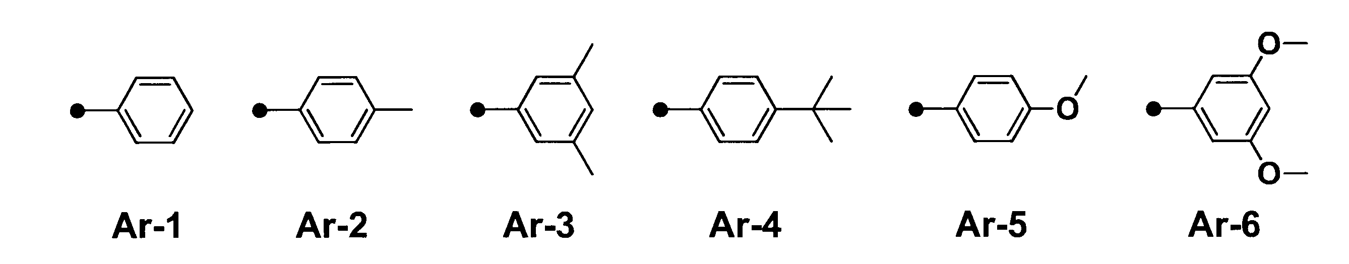


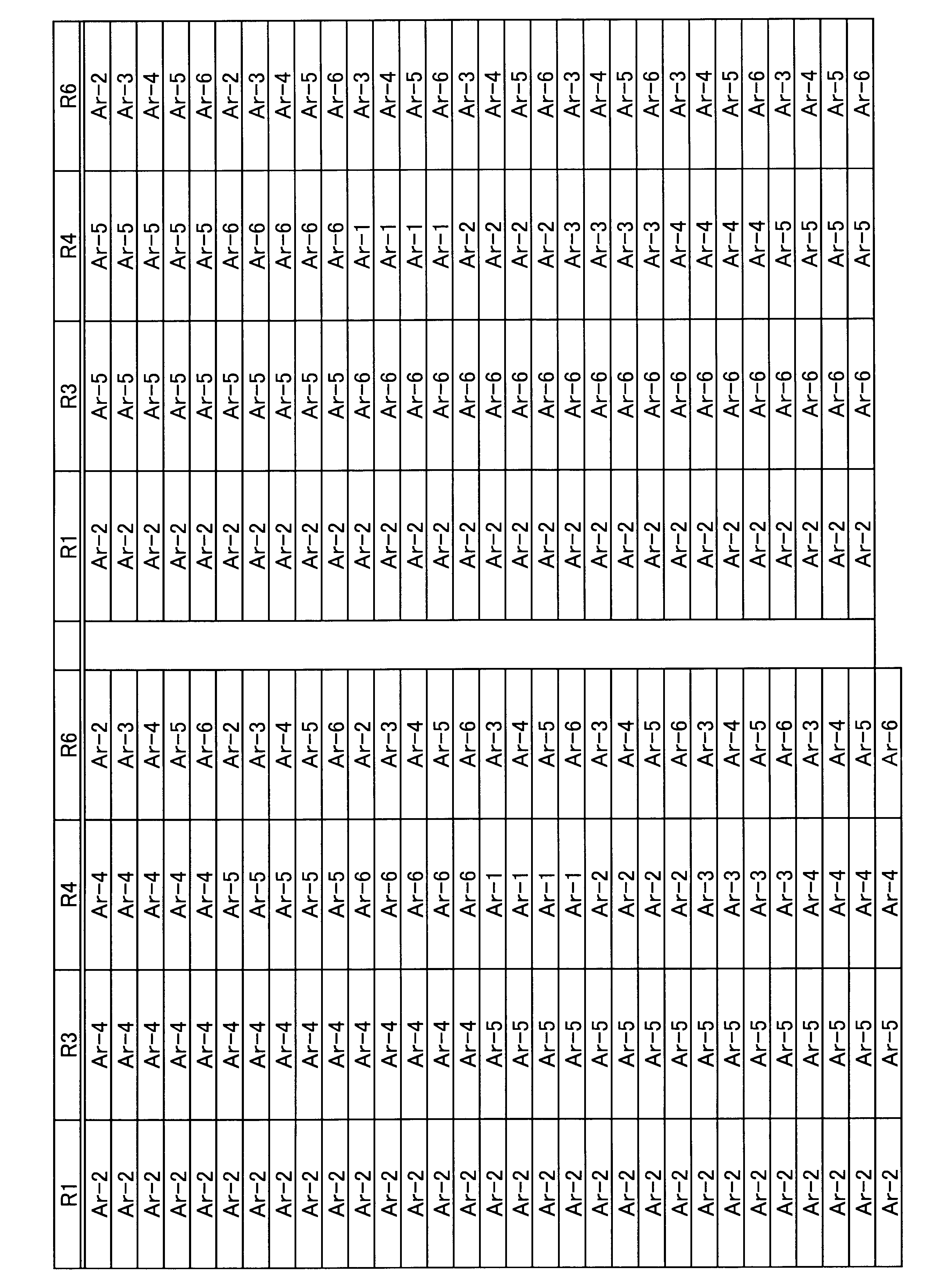


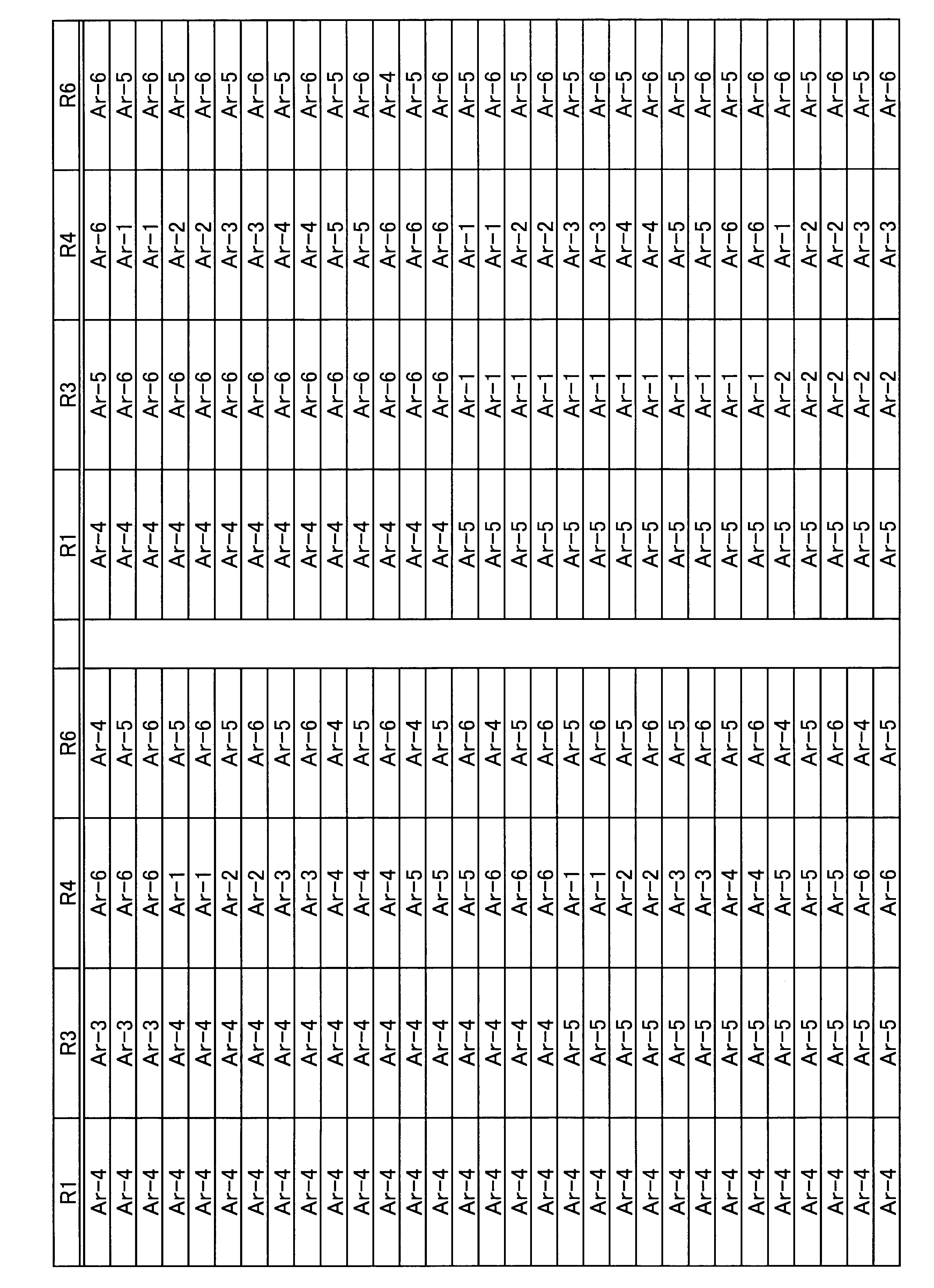


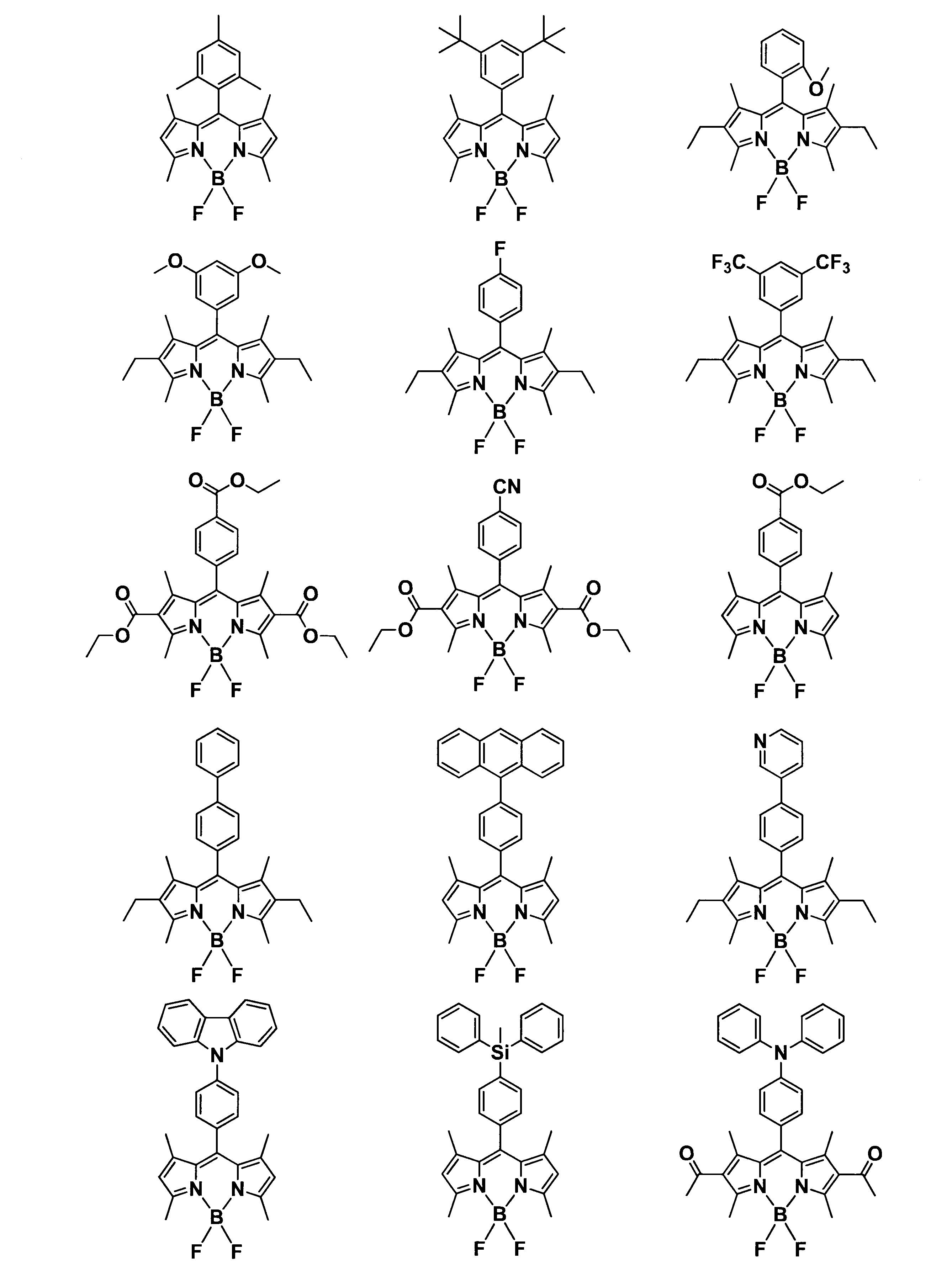


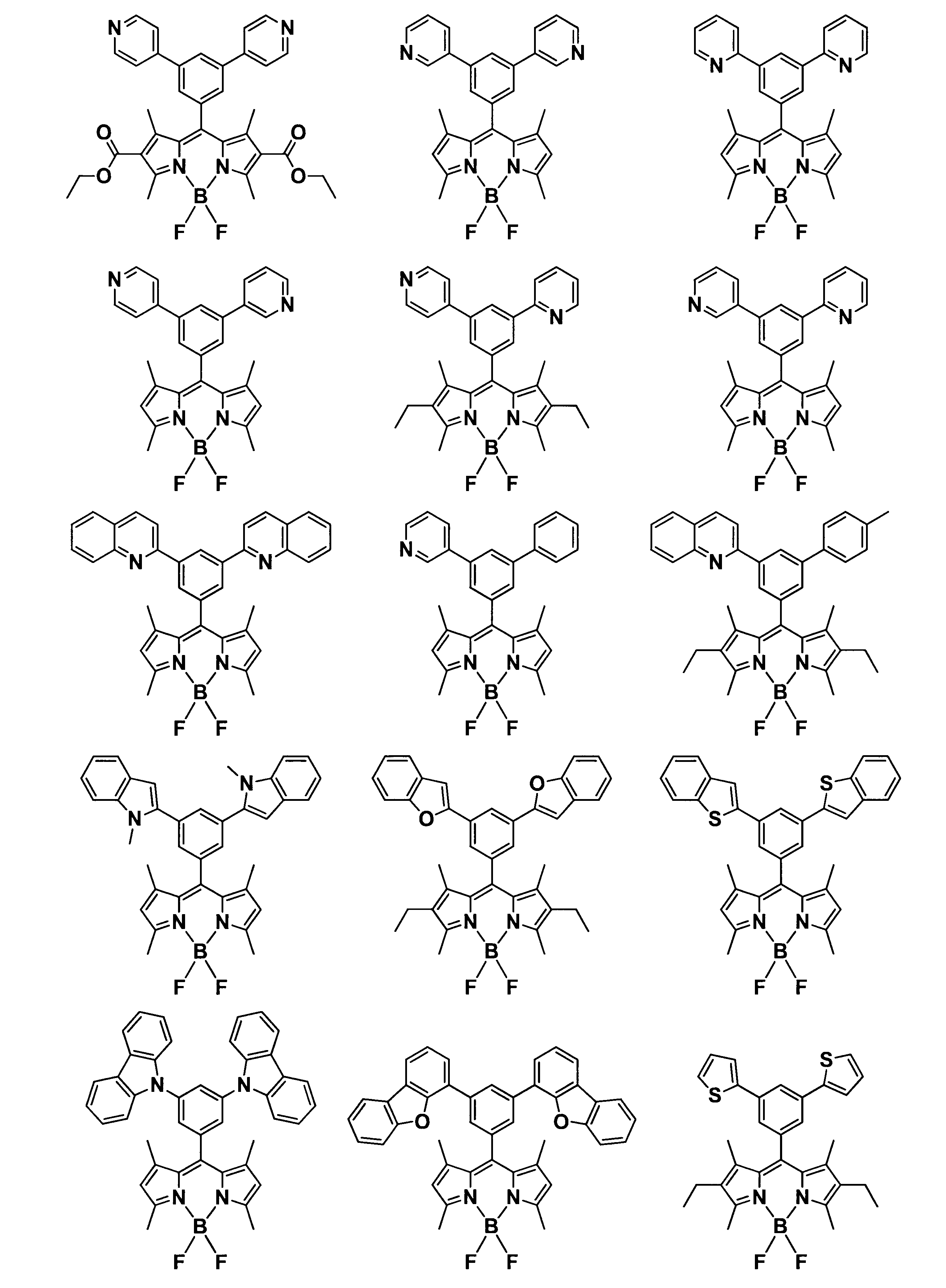


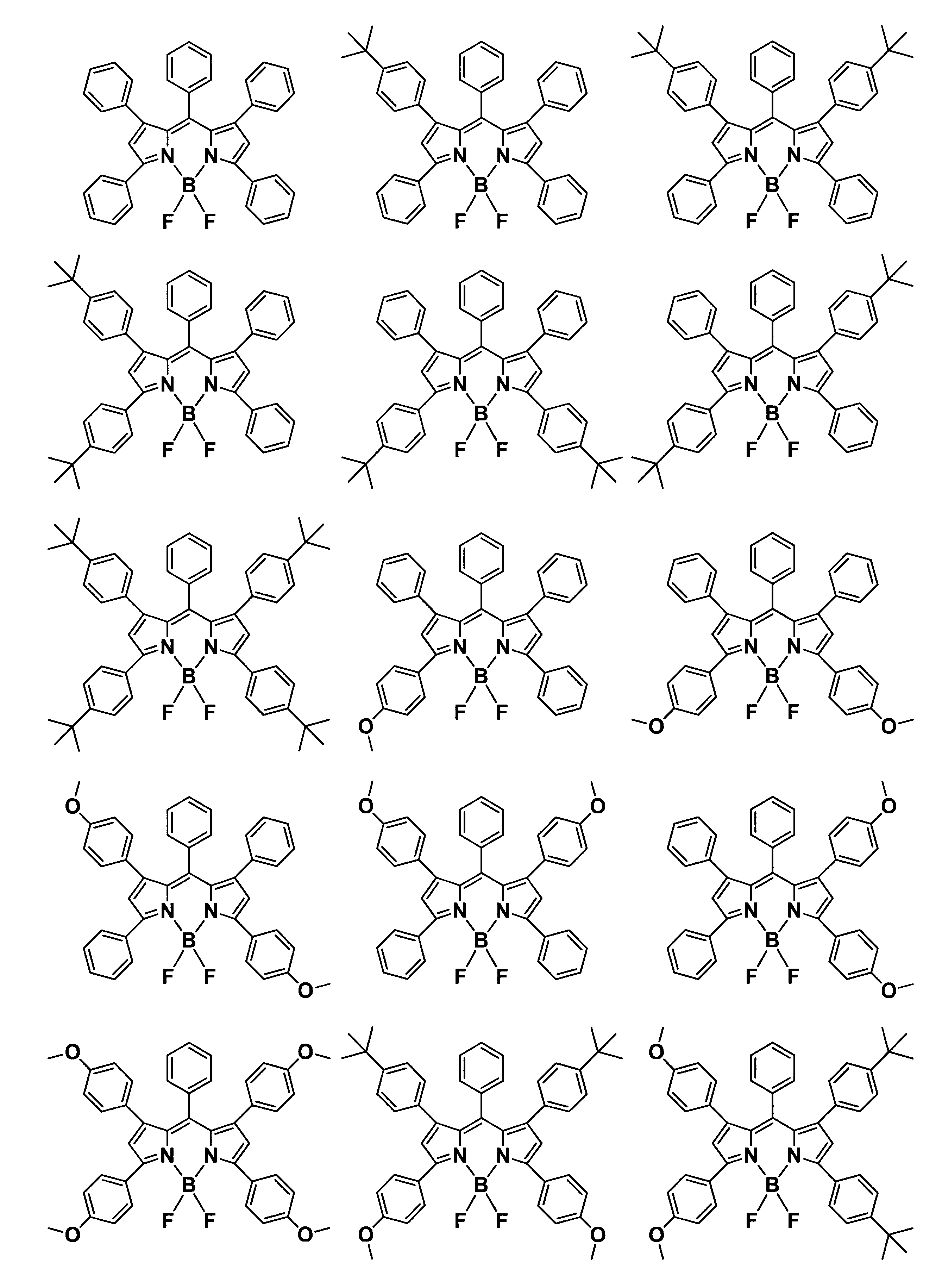


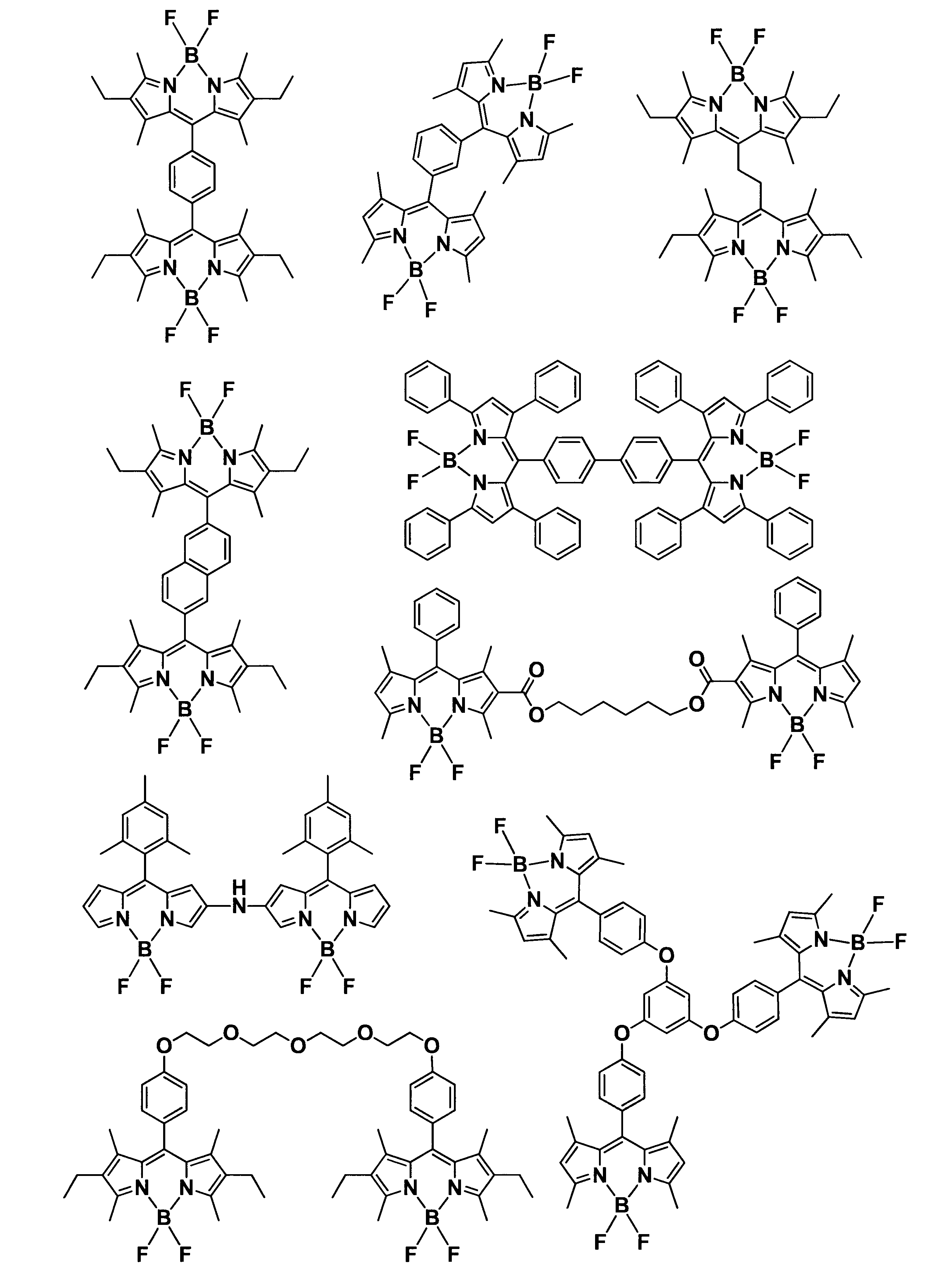


本発明に用いられる色変換フィルムにおけるバインダー樹脂は、連続相を形成するものであり、成型加工性、透明性、耐熱性等に優れる材料であれば良い。バインダー樹脂の例としては、例えばアクリル酸系、メタクリル酸系、ポリケイ皮酸ビニル系、環ゴム系等の反応性ビニル基を有する光硬化型レジスト材料、エポキシ樹脂、シリコーン樹脂(シリコーンゴム、シリコーンゲル等のオルガノポリシロキサン硬化物(架橋物)を含む)、ウレア樹脂、フッ素樹脂、ポリカーボネート樹脂、アクリル樹脂、ウレタン樹脂、メラミン樹脂、ポリビニル樹脂、ポリアミド樹脂、フェノール樹脂、ポリビニルアルコール樹脂、ポリビニルブチラール樹脂、セルロース樹脂、脂肪族エステル樹脂、芳香族エステル樹脂、脂肪族ポリオレフィン樹脂、芳香族ポリオレフィン樹脂などの公知のものが挙げられる。また、バインダー樹脂としては、これらの共重合樹脂を用いても構わない。これらの樹脂を適宜設計することで、本発明に用いられる色変換フィルムに有用なバインダー樹脂が得られる。
本発明に用いられる色変換フィルムは、上述した有機発光材料とバインダー樹脂以外に、酸化防止剤、加工および熱安定化剤、紫外線吸収剤等の耐光性安定化剤、塗布膜安定化のための分散剤やレベリング剤、可塑剤、エポキシ化合物などの架橋剤、アミン・酸無水物・イミダゾールなどの硬化剤、フィルム表面の改質剤としてシランカップリング剤等の接着補助剤、色変換材沈降抑制剤としてシリカ粒子やシリコーン微粒子等の無機粒子およびシランカップリング剤など、その他の添加剤を含有することができる。
本発明の積層部材および光源ユニットを構成する積層フィルムは、熱可塑性樹脂からなる必要がある。熱可塑性樹脂は一般的に熱硬化性樹脂や光硬化性樹脂と比べて安価であり、かつ公知の溶融押出により簡便かつ連続的にシート化することができることから、低コストで積層フィルムを得ることが可能となる。
|λ1-λ2|≦50 (ただし、λ1<λ2) (6)
λ1(nm):反射フィルムの反射帯域の低波長端近傍で反射率が最大反射率の1/4となる波長(nm)、λ2(nm):反射フィルムの反射帯域の低波長端近傍で反射率が最大反射率の3/4となる波長(nm)
以下に、本発明に用いられる色変換フィルムの原料である色変換組成物の作製方法の一例を説明する。この作製方法では、上述した有機発光材料、バインダー樹脂、溶媒等を所定量混合する。上記の成分を所定の組成になるよう混合した後、ホモジナイザー、自公転型攪拌機、3本ローラー、ボールミル、遊星式ボールミル、ビーズミル等の撹拌・混練機で均質に混合分散することで、有機発光材料が得られる。混合分散後、もしくは混合分散の過程で、真空もしくは減圧条件下で脱泡することも好ましく行われる。また、ある特定の成分を事前に混合することや、エージング等の処理をしても構わない。エバポレーターによって溶媒を除去して所望の固形分濃度にすることも可能である。
本発明において、色変換フィルムは、上述した有機発光材料またはその硬化物層(すなわち、色変換組成物の硬化物層)を含んでいればその構成に限定はない。その一例を図6~図9に示す。図6は、色変換フィルム4の一例を示す模式断面図であり、図7、図8、および図9はそれぞれ、実施の形態に係る積層部材5の一例を示す模式断面図である。図6~図9に示す符号41、42、および43はそれぞれ、基材層、色変換フィルムの有機発光材料からなる層(以下、色変換層と呼称する場合もある)、およびバリアフィルムである。
基材層としては、特に制限無く公知の金属、フィルム、ガラス、セラミック、紙等を使用することができる。具体的には、基材層として、アルミニウム(アルミニウム合金も含む)、亜鉛、銅、鉄などの金属板や箔、セルロースアセテート、ポリエチレンテレフタレート(PET)、ポリエチレン、ポリエステル、ポリアミド、ポリイミド、ポリフェニレンサルファイド、ポリスチレン、ポリプロピレン、ポリカーボネート、ポリビニルアセタール、アラミド、シリコーン、ポリオレフィン、熱可塑性フッ素樹脂、テトラフルオロエチレンとエチレンとの共重合体(ETFE)などのプラスチックのフィルム、α-ポリオレフィン樹脂、ポリカプロラクトン樹脂、アクリル樹脂、シリコーン樹脂およびこれらとエチレンとの共重合樹脂からなるプラスチックのフィルム、前記プラスチックがラミネートされた紙、または前記プラスチックによりコーティングされた紙、前記金属がラミネートまたは蒸着された紙、前記金属がラミネートまたは蒸着されたプラスチックフィルムなどが挙げられる。また、基材層が金属板である場合、その表面にクロム系やニッケル系などのメッキ処理やセラミック処理が施されていてもよい。
次に、本発明に用いられる色変換フィルムの有機発光材料からなる層(以下、色変換層とも称する)の作製方法の一例を説明する。この色変換層の作製方法では、上述した方法で作製した色変換組成物を、基材層やバリアフィルム層等の下地上に塗布し、乾燥させる。このようにして、色変換層を作製する。塗布は、リバースロールコーター、ブレードコーター、スリットダイコーター、ダイレクトグラビアコーター、オフセットグラビアコーター、キスコーター、ナチュラルロールコーター、エアーナイフコーター、ロールブレードコーター、バリバーロールブレードコーター、トゥーストリームコーター、ロッドコーター、ワイヤーバーコーター、アプリケーター、ディップコーター、カーテンコーター、スピンコーター、ナイフコーター等により行うことができる。色変換層の膜厚均一性を得るためにはスリットダイコーターで塗布することが好ましい。
バリアフィルムとしては、色変換層に対してガスバリア性を向上させる場合などにおいて適宜用いられる。このバリアフィルムとしては、例えば、酸化ケイ素、酸化アルミニウム、酸化チタン、酸化タンタル、酸化亜鉛、酸化スズ、酸化インジウム、酸化イットリウム、酸化マグネシウムなどの無機酸化物や、窒化ケイ素、窒化アルミニウム、窒化チタン、炭化窒化ケイ素などの無機窒化物、またはこれらの混合物、またはこれらに他の元素を添加した金属酸化物薄膜や金属窒化物薄膜、あるいはポリ塩化ビニル系樹脂、アクリル系樹脂、シリコン系樹脂、メラミン系樹脂、ウレタン系樹脂、フッ素系樹脂、酢酸ビニルのケン化物等のポリビニルアルコール系樹脂などの各種樹脂から成る膜を挙げることができる。
本発明の色変換フィルムにおいてそれぞれの層の間には、必要に応じて接着層を設けても良い。
本発明の積層部材においては、個別に作成した色変換フィルムと積層フィルムを接着層を介して貼り合せることも好ましい。接着層の好ましい形態は上述と同様である。
次に、本発明の実施の形態に係る積層部材および光源ユニットを構成する積層フィルムの好ましい作製方法を熱可塑性樹脂X,Yからなる積層フィルムを例にとり以下に説明する。もちろん本発明は係る例に限定して解釈されるものではない。また、本発明に用いる積層フィルムの積層構造は、特開2007-307893号公報の段落[0053]~[0063]に記載の内容と同様の方法により簡便に実現できるものである。
本発明の光源ユニットは、色変換フィルムのいずれか一方または両方の面に光拡散フィルムが積層されていることが好ましい。光源からの光のムラを軽減し、光を均一に拡散させる効果があると同時に、後述のプリズムシートと同様に集光の効果を示し、正面方向の輝度向上に寄与するからである。また、光源からの発光の指向性を軽減し、有機発光材料からの発光を色変換フィルムの外部へ取り出しやすくすることによって、光源からの発光と有機発光材料からの発光の比率を、最適な状態に調整する効果もある。
本発明の光源ユニットは、色変換フィルムの光出射面に、プリズムシートが設けられていることが好ましい。光源側から照射された光を集光することにより正面方向の輝度を向上させるとともに、バックライトの明るさを均一にするからである。ここで光出射面とは、ディスプレイ用途においては表示面側のことを指し、照明用途においては発光面側のことを指す。
光源の種類は、一般式(1)で表される化合物等の混合する発光物質が吸収可能な波長領域に発光を示すものであればいずれの光源でも用いることができる。例えば、熱陰極管や冷陰極管、無機ELなどの蛍光性光源、有機エレクトロルミネッセンス素子光源、LED、白熱光源、あるいは太陽光などいずれの光源でも原理的には利用可能であるが、特にはLEDが好適な光源であり、ディスプレイや照明用途では、青色光の色純度を高められる点で、400~500nmの範囲の光源を持つ青色LEDがさらに好適な光源である。


本発明の実施の形態に係る光源ユニットは、少なくとも光源、上述した色変換フィルムおよび上述した積層フィルムを備える構成である。光源と色変換フィルムの配置方法については特に限定されず、光源と色変換フィルムとを密着させた構成を取っても良いし、光源と色変換フィルムを離したリモートフォスファー形式を取っても良い。また、光源ユニットは、上述した色変換フィルムと上述した積層フィルムとを含む積層体を備えていてもよい。また、光源ユニットは、色純度を高める目的で、さらにカラーフィルターを備える構成を取っても良い。
本発明の実施の形態に係るディスプレイは、少なくとも、上述したように光源および色変換フィルム等を含む光源ユニットを備える。例えば、液晶ディスプレイ等のディスプレイには、バックライトユニットとして、上述の光源ユニットが用いられる。また、本発明の実施の形態に係る照明装置は、少なくとも、上述したように光源および色変換フィルム等を含む光源ユニットを備える。例えば、この照明装置は、光源ユニットとしての青色LED光源と、この青色LED光源からの青色光をこれよりも長波長の光に変換する色変換フィルムまたは色変換組成物とを組み合わせて、白色光を発光するように構成される。

化合物の1H-NMRは、超伝導FTNMR EX-270(日本電子(株)製)を用い、重クロロホルム溶液にて測定を行った。
化合物の吸収スペクトルは、U-3200形分光光度計(日立製作所(株)製)を用い、化合物をトルエンに1×10⁻⁶mol/Lの濃度で溶解させて測定を行った。
化合物の蛍光スペクトルは、F-2500形分光蛍光光度計(日立製作所(株)製)を用い、化合物をトルエンに1×10⁻⁶mol/Lの濃度で溶解させ、波長460nmで励起させた際の蛍光スペクトルを測定した。
フィルムの層構成は、ミクロトームを用いて断面を切り出したサンプルについて、透過型電子顕微鏡(TEM)を用いて観察することにより求めた。すなわち、透過型電子顕微鏡H-7100FA型((株)日立製作所製)を用い、加速電圧75kVの条件でフィルムの断面写真を撮影し、層構成を測定した。
日立製作所製 分光光度計(U-4100 Spectrophotomater)に付属の角度可変透過付属装置を取り付け、入射角度φ=10°および60°における波長250~800nmの絶対反射率を測定した。測定条件:スリットは2nm(可視)/自動制御(赤外)とし、ゲインは2と設定し、走査速度を600nm/分とした。サンプルをフィルム幅方向中央部から5cm×10cmで切り出し測定した。
浜松ホトニクス製ミニ分光光度器(C10083MMD)にNA0.22の光ファイバーを取り付け、光源の光を計測した。
評価用の光源を含む光源ユニットとして、Kindle Fire HDX 7のバックライトを用いた。本バックライトの発光におけるピーク波長は446nmである。この光源ユニットを用い、拡散板、積層フィルム、色変換フィルム(積層フィルムと色変換フィルムを含む積層部材の場合もある)、プリズムシート、偏光反射フィルムとした場合の輝度をコニカミノルタセンシング株式会社製分光放射輝度計を用いて測定した。比較例1における輝度を100としたときの相対的な輝度を表2に、比較例3における輝度を100としたときの相対的な輝度を表3に記載した。また、実施例26~33における相対輝度は、本測定方法で輝度測定を行い、実施例22と比較した値である。
輝度測定によりで得られた発光スペクトルデータと、カラーフィルターの透過率のスペクトルデータから、カラーフィルターにより色純度を向上させた場合の(u’、v’)色空間における色域を算出した。また、算出された(u’、v’)色空間における色域の面積は、BT.2020規格の色域面積を100%とした場合の割合により評価した。この割合が高いほど色再現性が良好である。
紫外線照射時に色変換フィルムで発生するラジカルの測定には、電子スピン共鳴装置JES-X3(日本電子(株)製)を用いた。超高圧水銀灯USH-250D(ウシオライティング(株)製)の波長365nmにおける照度を80mW/cm2に設定し、超高圧水銀灯、積層フィルム、色変換フィルムの順に配置させた後、液体窒素温度にて10分間紫外線を照射した。その後、温度40Kに調整した電子スピン共鳴装置に色変換フィルムを入れて、g値およびラジカル発生量を測定した。
g=(hν)/(μBH)
に代入して求められる。ここで、hはプランク定数、μBはボーア磁子である。
評価用の光源を含む光源ユニットとして、Sony製KD-65X9500Bの光源ユニットと液晶ディスプレイを用いた。本バックライトの発光における発光帯域は430~485nmである。本液晶ディスプレイを50℃雰囲気下光源点灯条件で1000h試験し、試験前後での色目、輝度の評価をコニカミノルタセンシング株式会社製分光放射輝度計を用いた。判定基準は以下のとおりである。
◎:試験前後でのΔu’v’0.03未満、輝度変化3%未満
○:試験前後でのΔu’v’0.10未満、輝度変化10%未満
×:試験前後でのΔu’v’0.10以上、輝度変化10%以上。
以下に、本発明における合成例1の化合物G-1の合成方法について説明する。化合物G-1の合成方法では、3,5-ジブロモベンズアルデヒド(3.0g)、4-t-ブチルフェニルボロン酸(5.3g)、テトラキス(トリフェニルホスフィン)パラジウム(0)(0.4g)、炭酸カリウム(2.0g)をフラスコに入れ、窒素置換した。これに、脱気したトルエン(30mL)および脱気した水(10mL)を加え、4時間還流した。この反応溶液を室温まで冷却し、有機層を、分液した後に飽和食塩水で洗浄した。この有機層を硫酸マグネシウムで乾燥し、ろ過後、溶媒を留去した。得られた反応生成物をシリカゲルクロマトグラフィーにより精製し、3,5-ビス(4-t-ブチルフェニル)ベンズアルデヒド(3.5g)を白色固体として得た。
以下に、本発明における合成例2の化合物R-1の合成方法について説明する。化合物R-1の合成方法では、4-(4-t-ブチルフェニル)-2-(4-メトキシフェニル)ピロール(300mg)、2-メトキシベンゾイルクロリド(201mg)およびトルエン(10mL)の混合溶液を窒素気流下、120℃で6時間加熱した。この加熱溶液を室温に冷却後、エバポレートした。ついで、エタノール(20ml)で洗浄し、真空乾燥した後、2-(2-メトキシベンゾイル)-3-(4-t-ブチルフェニル)-5-(4-メトキシフェニル)ピロール(260mg)を得た。
1H-NMR(CDCl3,ppm):1.19(s,18H)、3.42(s,3H)、3.85(s,6H)、5.72(d,1H)、6.20(t,1H)、6.42-6.97(m,16H),7.89(d,4H)。
積層フィルムは以下に示す方法にて得た。
熱可塑性樹脂XからなるX層の層数を51層、熱可塑性樹脂YからなるY層の層数を50層とした以外は、実施例1と同様にして積層フィルム、色変換フィルムならびに積層部材を得た。
熱可塑性樹脂XからなるX層の層数を101層、熱可塑性樹脂YからなるY層の層数を100層とした以外は、実施例1と同様にして積層フィルム、色変換フィルムならびに積層部材を得た。
熱可塑性樹脂XからなるX層の層数を301層、熱可塑性樹脂YからなるY層の層数を300層とした以外は、実施例1と同様にして積層フィルム、色変換フィルムならびに積層部材を得た。
易接着層をインラインコートにて設けないこと以外は、実施例4と同様にして積層フィルム、色変換フィルムならびに積層部材を得た。
実施例1と同様に作製した色変換層となる部材を、PETフィルム(“ルミラー”U48、厚さ50μm)上に塗布し、100℃で1時間加熱、乾燥して平均膜厚10μmの色変換層を形成した。次に、上記色変換層の上に、PETフィルム(“ルミラー”U48、厚さ50μm)を加温ラミネートすることで、色変換フィルムを作成した。積層フィルムと上記色変換フィルムとを貼り合わせることなく積層部材としないこと以外は、実施例5と同様に積層フィルムならびに色変換フィルムを得た。
実施例4と同様に得られた積層フィルム上に、以下の方法で表面凹凸を設けた。
(塗剤1)
アデカオプトマー KRM-2199(旭電化工業(株)製) 10質量部
アロンオキセタン OXT-221(東亞合成(株)製) 1質量部
アデカオプトマー SP170(旭電化工業(株)製) 0.25質量部
この塗剤1をコーティングした面に、長手方向に垂直な断面形状が凹型の溝が複数掘り込まれた金型を押しあて、コーティングした面の裏面から超高圧水銀灯により1J/m2照射して塗剤を硬化させ、金型を離型しレンズ形状を得た。ここで得られたレンズ形状は、ピッチ2μm、高さ1μmのプリズム形状を有するものであった。
熱可塑性樹脂XとしてPENを用いた以外は、実施例3と同様にして積層フィルム、色変換フィルムならびに積層部材を得た。この積層部材ならびにそれを含む光源ユニットの評価結果を表2に示すが、実施例3と同等の発光材料の発光波長での反射率を示すものの、光源波長での反射率の高さを反映して、わずかに輝度の低いものとなっていた。
積層フィルムを用いない構成とした以外は実施例1と同様に色変換フィルムを用いて光源ユニットを形成した。
色変換フィルムとして、Kindle Fire HDX 7にもともと搭載されていた無機材料からなる色変換フィルムを用いて、実施例6と同様に積層フィルムならびに色変換フィルムを得た。
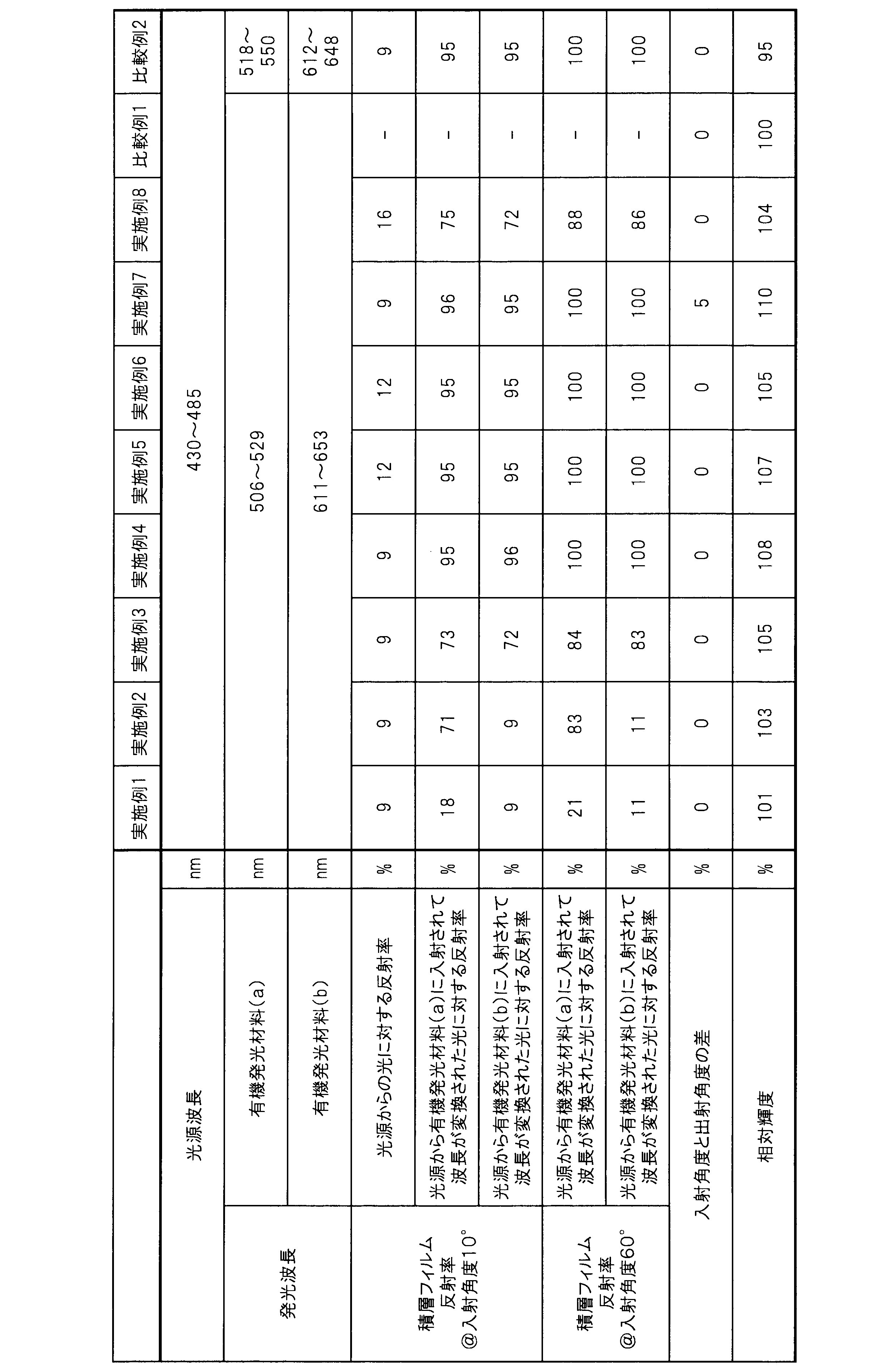
まず、積層フィルムを実施例1と同様の方法にて得た。続いて、有機発光材料を含む色変換フィルム、ならびに積層部材を以下の方法にて得た。
熱可塑性樹脂XからなるX層の層数を51層、熱可塑性樹脂YからなるY層の層数を50層とした以外は、実施例9と同様にして積層フィルム、色変換フィルムならびに積層部材を得た。
熱可塑性樹脂XからなるX層の層数を101層、熱可塑性樹脂YからなるY層の層数を100層とした以外は、実施例9と同様にして積層フィルム、色変換フィルムならびに積層部材を得た。
熱可塑性樹脂XからなるX層の層数を301層、熱可塑性樹脂YからなるY層の層数を300層とした以外は、実施例9と同様にして積層フィルム、色変換フィルムならびに積層部材を得た。
易接着層をインラインコートにて設けないこと以外は、実施例12と同様にして積層フィルム、色変換フィルムならびに積層部材を得た。
スリットダイコーターを用いて実施例9と同様に作製した(A)層作製用の色変換組成物を、PETフィルム(“ルミラー”U48、厚さ50μm)上に塗布し、100℃で20分加熱、乾燥して平均膜厚16μmの(A)層を形成した。同様に、スリットダイコーターを用いて実施例9と同様に作製した(B)層作製用の色変換組成物を、基材層Bである光拡散フィルム“ケミカルマット”125PW((株)きもと製、厚さ138μm)のPET基材層側に塗布し、100℃で20分加熱、乾燥して平均膜厚48μmの(B)層を形成した。次に、上記2つのユニットを、(A)層と(B)層とが直接積層するように加温ラミネートすることで、「PETフィルム/(A)層/(B)層/基材層/光拡散層」という構成の色変換フィルムを作製した。積層フィルムと上記色変換フィルムとを貼り合わせることなく積層部材としないこと以外は、実施例13と同様に積層フィルムならびに色変換フィルムを得た。
色変換フィルムの有機発光材料(a)として化合物G-2を用いた以外は、実施例12と同様にして積層フィルム、色変換フィルムならびに積層部材を得た。
色変換フィルムの有機発光材料(b)として化合物R-2を用いた以外は、実施例12と同様にして積層フィルム、色変換フィルムならびに積層部材を得た。
色変換フィルムの有機発光材料(a)として化合物G-3を用いた以外は、実施例12と同様にして積層フィルム、色変換フィルムならびに積層部材を得た。
光拡散フィルムの代わりにPETフィルム“ルミラー”U48(東レ(株)製、厚さ50μm)を用いたこと以外は、実施例12と同様にして積層フィルム、色変換フィルムならびに積層部材を作製した。
光源として、ピーク波長が458nmの青色LEDを用いた以外は、実施例12と同様にして積層フィルム、色変換フィルムならびに積層部材を得た。
積層フィルムを用いない構成とした以外は実施例9と同様に色変換フィルムを用いて光源ユニットを形成した。
色変換フィルムとして、Kindle Fire HDX 7にもともと搭載されていた無機材料からなる色変換フィルムを用いて、実施例14と同様に積層フィルムならびに色変換フィルムを得た。
色変換フィルムの発光材料として、Y3Al5O12(YAG)およびCaAlSiN3(CASN)を用いた以外は、実施例12と同様に積層フィルムならびに色変換フィルムを得た。評価結果を表3に示す。実施例12に対比して色域の面積が低下しており、有機発光材料との組み合わせが優れることを示す結果となった。

以下に示す方法にて紫外線カット型の積層フィルムを得た。熱可塑性樹脂Xとして、融点が258℃のポリエチレンテレフタレート(PET)を用いた。また熱可塑性樹脂Yとして融点を持たない非晶性樹脂であるスピログリコール25mol%、シクロヘキサンジカルボン酸30mol%共重合したエチレンテレフタレート(PE/SPG・T/CHDC)を用いた。また、熱可塑性樹脂Yには、紫外線吸収剤として分子量が650g/mol、吸収最大波長が346nmであるベンゾトリアゾール系の紫外線吸収剤(2,2’-メチレンビス(4-(1,1,3,3-テトラメチルブチル)-6-(2H-ベンゾトリアゾール-2-イル)フェノール)を20wt%となるように添加した。
熱可塑性樹脂XからなるX層の層数を301層、熱可塑性樹脂YからなるY層の層数を300層とした以外は、実施例20と同様にして積層フィルムならびに色変換フィルムを得た。
分子量が700g/molで吸収最大波長が355nmであるトリアジン系紫外線吸収剤(2,4,6-トリス(2-ヒドロキシ-4-ヘキシルオキシ-3-メチルフェニル)-s-トリアジン)を、熱可塑性樹脂Y全体に対して16wt%となるように添加した以外は、実施例21と同様にして積層フィルムならびに色変換フィルムを得た。
分子量が700g/molで吸収最大波長が355nmであるトリアジン系紫外線吸収剤(2,4,6-トリス(2-ヒドロキシ-4-ヘキシルオキシ-3-メチルフェニル)-s-トリアジン)を、熱可塑性樹脂Y全体に対して3wt%となるように添加した以外は、実施例21と同様にして積層フィルムならびに色変換フィルムを得た。
実施例23において、2,4-ビス(2-ヒドロキシ-4-ブトキシフェニル)-6-(2,4-ジブトキシフェニル)-s-トリアジンを硬化性樹脂からなる層に3wt%添加し、吸収最大波長が378nmのアゾメチン系色素を熱可塑性樹脂Y内に3wt%添加した以外は、実施例23と同様にして積層フィルムを得た。
実施例23において、熱可塑性樹脂Yにトリアジン系紫外線吸収剤(2,4,6-トリス(2-ヒドロキシ-4-ヘキシルオキシ-3-メチルフェニル)-s-トリアジン)(熱可塑性樹脂Y全体に対して1wt%)とベンゾトリアゾール系の紫外線吸収剤(2,2’-メチレンビス(4-(1,1,3,3-テトラメチルブチル)-6-(2H-ベンゾトリアゾール-2-イル)フェノール)(熱可塑性樹脂Y全体に対して1wt%)を、硬化性樹脂にインドール系可視光線吸収色素(硬化性樹脂全体に対して1wt%)と吸収最大波長が384nmのアントラキノン系可視光線吸収色素(硬化性樹脂全体に対して7wt%)を添加した以外は、実施例23と同様に積層フィルムを得た。
フィルム厚みを65μmとし、トリアジン系紫外線吸収剤の熱可塑性樹脂Yへの添加量を6wt%とした以外は、実施例22と同様に積層フィルムを得た。
隣接する層厚みの比を1.5とし、かつトリアジン系紫外線吸収剤の熱可塑性樹脂Yへの添加量を4wt%とした以外は、実施例22と同様に積層フィルムを得た。
フィルム厚みを65μmとし、熱可塑性樹脂Yにトリアジン系紫外線吸収剤(2,4,6-トリス(2-ヒドロキシ-4-ヘキシルオキシ-3-メチルフェニル)-s-トリアジン)(熱可塑性樹脂Y全体に対して0.4wt%)とベンゾトリアゾール系の紫外線吸収剤(2,2’-メチレンビス(4-(1,1,3,3-テトラメチルブチル)-6-(2H-ベンゾトリアゾール-2-イル)フェノール)(熱可塑性樹脂Y全体に対して0.4wt%)を添加した以外は、実施例25と同様に積層フィルムを得た。

実施例22と同様にして得られた積層フィルムを第1の積層フィルムとした。また、フィルム厚みを65μmとし紫外線吸収剤を用いず実施例22と同様にして得た積層フィルムを第2の積層フィルムとした。
フィルム厚みを65μmとし紫外線吸収剤を用いず実施例22と同様にして得た積層フィルムを第1の積層フィルムとした。また、実施例22と同様に得た積層フィルムを第2の積層フィルムとした。
実施例30にて得られた第1および第2積層フィルム、色変換フィルムを光源、第1の積層フィルム、色変換フィルム、第2の積層フィルムとなるように配置させ、特に第2の積層フィルムを液晶ディスプレイの外側に粘着フィルムを介して貼り付けて耐光性試験を実施した。評価結果を表5に示す。実施例30とほぼ同様の輝度向上性能と耐光性を示すものであった。
色変換フィルムを製造する際に、PETフィルムに代わり実施例26で得られた積層フィルムを用いて色変換フィルムを得た。
色変換フィルムを製造する際に、PETフィルムに代わり実施例15で得られた積層フィルム(第1の積層フィルム)を用いて色変換フィルムを得、さらに実施例22で得られた積層フィルム(第2の積層フィルム)を粘着フィルムを介して貼り合わせた。
積層フィルムを用いない構成とした以外は実施例20と同様に色変換フィルムを用いて光源ユニットを形成し耐光性試験を実施した。評価結果を表5に示す。耐光性が著しく低く、実使用には適さないものであった。
積層フィルムの代わりに、ポリエチレンテレフタレート(PET)にベンゾトリアゾール系の紫外線吸収剤を10wt%添加し、1層のフィルムとして実施例20と同様に厚みが30μmの単層フィルムを得た。

2 光源
3 積層フィルム
4 色変換フィルム
5 積層部材
6 導光板
31 凹凸形状の例
32 凹凸形状の例
33 機能層
41 基材層
42 色変換層
43 バリアフィルム
Claims (30)
- 光源と、
前記光源から入射された入射光を前記入射光よりも長波長の光に変換する有機発光材料を含む色変換フィルムと、
異なる複数の熱可塑性樹脂が交互に11層以上積層されてなる積層フィルムと、
を含むことを特徴とする光源ユニット。 - 前記積層フィルムは、前記有機発光材料によって前記入射光よりも長波長に変換された光の、入射角度60°における反射率が70%以上である積層フィルムであることを特徴とする請求項1に記載の光源ユニット。
- 前記積層フィルムは、前記光源から前記積層フィルムに入射される入射光の、入射角度10°における反射率が20%以下である積層フィルムであることを特徴とする請求項1または2に記載の光源ユニット。
- 前記有機発光材料が、ピロメテン誘導体を含むことを特徴とする請求項1~3のいずれか1項に記載の光源ユニット。
- 前記有機発光材料が一般式(1)で表される化合物を含有することを特徴とする請求項1~4のいずれか1項に記載の光源ユニット。

- 一般式(1)において、XがC-R7であり、R7が一般式(2)で表される基であることを特徴とする請求項5に記載の光源ユニット。

- 一般式(1)において、R1、R3、R4およびR6がそれぞれ同じでも異なっていてもよく、置換もしくは無置換のフェニル基であることを特徴とする請求項5または6に記載の光源ユニット。
- 一般式(1)において、R1、R3、R4およびR6がそれぞれ同じでも異なっていてもよく、置換もしくは無置換のアルキル基であることを特徴とする請求項5または6に記載の光源ユニット。
- 前記有機発光材料のピーク波長が500nm以上580nm以下の領域に観測される発光を呈することを特徴とする請求項1~8のいずれか1項に記載の光源ユニット。
- 前記有機発光材料が以下の有機発光材料(a)および(b)を含有することを特徴とする請求項1~9のいずれか1項に記載の光源ユニット。
(a)光源から入射された入射光により励起されることにより、ピーク波長が500nm以上580nm以下の領域に観測される発光を呈する有機発光材料
(b)光源から入射された入射光もしくは有機発光材料(a)からの発光の少なくとも一方により励起されることにより、ピーク波長が580nm以上750nm以下の領域に観測される発光を呈する有機発光材料 - 前記有機発光材料(a)もしくは(b)のいずれか一方または両方が一般式(1)で表される化合物であることを特徴とする請求項10に記載の光源ユニット。

- 前記色変換フィルムが少なくとも以下の(A)層および(B)層を含む積層体であることを特徴とする請求項1~11のいずれか1項に記載の光源ユニット。
(A)光源から入射された入射光により励起されることにより、ピーク波長が500nm以上580nm以下の領域に観測される発光を呈する有機発光材料(a)を含有する層
(B)光源から入射された入射光もしくは有機発光材料(a)からの発光の少なくとも一方により励起されることにより、ピーク波長が580nm以上750nm以下の領域に観測される発光を呈する有機発光材料(b)を含有する層 - 前記色変換フィルムと前記積層フィルムとを含む積層体を有することを特徴とする請求項1~12のいずれか1項に記載の光源ユニット。
- 前記色変換フィルムのいずれか一方または両方の面に光拡散フィルムが積層されてなることを特徴とする請求項1~13のいずれか1項に記載の光源ユニット。
- 前記色変換フィルムの光出射面に、プリズムシートが設けられてなることを特徴とする請求項1~14のいずれか1項に記載の光源ユニット。
- 前記色変換フィルムまたは前記積層フィルムの表面に機能層が設けられてなり、前記積層フィルムの屈折率をn1、前記色変換フィルムの屈折率をn2としたとき、前記機能層の屈折率n3がn1とn2の間となることを特徴とする請求項1~15のいずれか1項に記載の光源ユニット。
- 前記積層フィルムまたは前記色変換フィルムの表面が凹凸形状を有することを特徴とする請求項1~16のいずれか1項に記載の光源ユニット。
- 前記凹凸形状がレンズ形状、略三角形状、または略半円形状であることを特徴とする請求項17に記載の光源ユニット。
- 前記積層フィルムまたは色変換フィルムが、前記光源から前記積層フィルムまたは色変換フィルムに入射される入射光の入射角度と出射光の出射角度との差が5°以上であることを特徴とする請求項1~18のいずれか1項に記載の光源ユニット。
- 前記積層フィルムが、入射角度10°において波長300nm以上410nm以下の光の反射率が20%以上、または入射角度10°において300nm以上410nm以下の光の吸収率が10%以上であることを特徴とする請求項3に記載の光源ユニット。
- 前記積層フィルムが紫外線吸収剤を含むことを特徴とする請求項3または20に記載の光源ユニット。
- 前記積層フィルムの少なくとも片面に紫外線吸収剤を含む樹脂層を含むことを特徴とする請求項3、20または21に記載の光源ユニット。
- 前記紫外線吸収剤が、アントラキノン、アゾメチン、インドール、トリアジン、ナフタルイミド、フタロシアニンのいずれかの骨格を有する紫外線吸収剤を含むことを特徴とする請求項21または22に記載の光源ユニット。
- 前記積層フィルムが、前記光源と前記色変換フィルムの間に設けられてなることを特徴とする請求項1~23のいずれか1項に記載の光源ユニット。
- 前記光源が400nm以上500nm以下の範囲に極大発光を有する発光ダイオードであることを特徴とする請求項1~24のいずれか1項に記載の光源ユニット。
- 前記光源が430nm以上470nm以下の範囲に極大発光を有し、かつ発光波長領域が400nm以上500nm以下の範囲を有する発光ダイオードであって、光源の発光スペクトルが、数式(3)を満たすことを特徴とする請求項25に記載の光源ユニット。

- 前記光源が455nm以上465nm以下の範囲に極大発光を有することを特徴とする請求項26に記載の光源ユニット。
- 入射光を前記入射光よりも長波長の光に変換する有機発光材料を含む色変換フィルムと、異なる複数の熱可塑性樹脂が交互に11層以上積層されてなる積層フィルムとを含むことを特徴とする積層部材。
- 請求項1~27のいずれか1項に記載の光源ユニットを備えることを特徴とするディスプレイ。
- 請求項1~27のいずれか1項に記載の光源ユニットを備えることを特徴とする照明装置。
Priority Applications (6)
| Application Number | Priority Date | Filing Date | Title |
|---|---|---|---|
| CN201780018044.9A CN108780169B (zh) | 2016-03-25 | 2017-03-21 | 光源单元、层叠构件及使用它们的显示器及照明装置 |
| EP17770197.6A EP3435124B1 (en) | 2016-03-25 | 2017-03-21 | Light source unit, lamination member, and display and illumination device in which same is used |
| KR1020187027179A KR102022817B1 (ko) | 2016-03-25 | 2017-03-21 | 광원 유닛, 적층 부재, 그리고 그것들을 사용한 디스플레이 및 조명 장치 |
| JP2017516538A JP6344527B2 (ja) | 2016-03-25 | 2017-03-21 | 光源ユニット、積層部材ならびにそれらを用いたディスプレイおよび照明装置 |
| US16/086,694 US10784414B2 (en) | 2016-03-25 | 2017-03-21 | Light source unit, laminated member, and display and lighting apparatus including them |
| MYPI2018001591A MY188668A (en) | 2016-03-25 | 2017-03-21 | Light source unit, laminated member, and display and lighting apparatus including them |
Applications Claiming Priority (6)
| Application Number | Priority Date | Filing Date | Title |
|---|---|---|---|
| JP2016-061334 | 2016-03-25 | ||
| JP2016061334 | 2016-03-25 | ||
| JP2016-061328 | 2016-03-25 | ||
| JP2016061328 | 2016-03-25 | ||
| JP2016224730 | 2016-11-18 | ||
| JP2016-224730 | 2016-11-18 |
Publications (1)
| Publication Number | Publication Date |
|---|---|
| WO2017164155A1 true WO2017164155A1 (ja) | 2017-09-28 |
Family
ID=59899481
Family Applications (1)
| Application Number | Title | Priority Date | Filing Date |
|---|---|---|---|
| PCT/JP2017/011153 WO2017164155A1 (ja) | 2016-03-25 | 2017-03-21 | 光源ユニット、積層部材ならびにそれらを用いたディスプレイおよび照明装置 |
Country Status (8)
| Country | Link |
|---|---|
| US (1) | US10784414B2 (ja) |
| EP (1) | EP3435124B1 (ja) |
| JP (2) | JP6344527B2 (ja) |
| KR (1) | KR102022817B1 (ja) |
| CN (1) | CN108780169B (ja) |
| MY (1) | MY188668A (ja) |
| TW (2) | TWI709258B (ja) |
| WO (1) | WO2017164155A1 (ja) |
Cited By (13)
| Publication number | Priority date | Publication date | Assignee | Title |
|---|---|---|---|---|
| WO2018083953A1 (ja) * | 2016-11-07 | 2018-05-11 | 東レ株式会社 | 光源ユニット |
| CN108303822A (zh) * | 2018-01-23 | 2018-07-20 | 青岛海信电器股份有限公司 | 一种背光模组、显示装置及液晶电视 |
| JP2019077861A (ja) * | 2017-10-26 | 2019-05-23 | 東レ株式会社 | 着色樹脂組成物、カラーフィルタ基板および表示装置 |
| WO2019146519A1 (ja) * | 2018-01-23 | 2019-08-01 | 東レ株式会社 | 赤色積層基板、カラーフィルター基板、画像表示装置およびディスプレイ用基板 |
| JP2020507921A (ja) * | 2017-11-28 | 2020-03-12 | エルジー・ケム・リミテッド | 色変換フィルムを含む照明モジュール |
| WO2020050144A1 (ja) * | 2018-09-06 | 2020-03-12 | 東レ株式会社 | 色変換材料、色変換部材、光源ユニット、ディスプレイ、照明装置、色変換基板およびインク |
| TWI738433B (zh) * | 2020-01-09 | 2021-09-01 | 致伸科技股份有限公司 | 光源模組以及具有光源模組的電子裝置 |
| US20210347790A1 (en) * | 2018-10-15 | 2021-11-11 | Lg Chem, Ltd. | Compound and color conversion film comprising same |
| JPWO2022059582A1 (ja) * | 2020-09-17 | 2022-03-24 | ||
| US11549025B2 (en) * | 2018-06-29 | 2023-01-10 | Lg Chem, Ltd. | Film for blocking ultraviolet rays |
| WO2023042751A1 (ja) | 2021-09-16 | 2023-03-23 | 東レ株式会社 | 色変換部材、それを含む光源ユニット、ディスプレイおよび照明装置 |
| TWI805492B (zh) * | 2022-09-22 | 2023-06-11 | 元璋玻璃股份有限公司 | 發光屏幕組、發光屏幕及其製作方法 |
| WO2023161740A1 (en) * | 2022-02-22 | 2023-08-31 | 3M Innovative Properties Company | Optical films for display systems |
Families Citing this family (19)
| Publication number | Priority date | Publication date | Assignee | Title |
|---|---|---|---|---|
| EP3418781B1 (en) * | 2016-02-19 | 2021-06-16 | Toray Industries, Inc. | Color conversion sheet, light source unit comprising same, display and lighting device |
| CN108780169B (zh) | 2016-03-25 | 2020-06-05 | 东丽株式会社 | 光源单元、层叠构件及使用它们的显示器及照明装置 |
| WO2019098109A1 (ja) * | 2017-11-16 | 2019-05-23 | Jsr株式会社 | レジスト下層膜形成用組成物、レジスト下層膜及びその形成方法、パターニングされた基板の製造方法並びに化合物 |
| JP7194925B2 (ja) | 2018-01-10 | 2022-12-23 | 興人フィルム&ケミカルズ株式会社 | 二軸延伸ポリブチレンテレフタレートフィルムを含む真空成形用又は真空圧空成形用包材 |
| CN108508654A (zh) * | 2018-04-08 | 2018-09-07 | 青岛海信电器股份有限公司 | 一种背光模组及液晶显示装置 |
| KR102568654B1 (ko) * | 2018-04-10 | 2023-08-23 | 삼성디스플레이 주식회사 | 백라이트 유닛, 백라이트 유닛을 포함하는 표시 장치 및 표시 장치를 제조하는 방법 |
| DE102018126355B4 (de) * | 2018-10-23 | 2021-06-17 | OSRAM Opto Semiconductors Gesellschaft mit beschränkter Haftung | Lichtemittierendes bauelement und verwendung eines lichtemittierenden bauelements zur minimierung von stokesverlusten durch photonmultiplikationsprozesse für ir-anwendungen |
| EP3757630B1 (en) * | 2018-11-12 | 2022-07-20 | Lg Chem, Ltd. | Display device comprising a back light unit comprising a colour conversion film |
| EP3757631B1 (en) * | 2018-11-12 | 2022-09-14 | Lg Chem, Ltd. | Colour conversion film, and back light unit and display device comprising same |
| CN109499837B (zh) * | 2018-12-29 | 2023-08-29 | 新疆天研种子机械工程技术研究中心(有限公司) | 一种辣椒清选分离系统 |
| KR20200096363A (ko) * | 2019-02-01 | 2020-08-12 | 삼성디스플레이 주식회사 | 표시 장치 및 그 제조 방법 |
| JPWO2020195786A1 (ja) * | 2019-03-27 | 2020-10-01 | ||
| US11094530B2 (en) | 2019-05-14 | 2021-08-17 | Applied Materials, Inc. | In-situ curing of color conversion layer |
| US11239213B2 (en) * | 2019-05-17 | 2022-02-01 | Applied Materials, Inc. | In-situ curing of color conversion layer in recess |
| KR102626377B1 (ko) * | 2019-06-12 | 2024-01-19 | 삼성디스플레이 주식회사 | 백라이트 유닛 및 이를 구비한 표시 장치 |
| KR20210006117A (ko) | 2019-07-08 | 2021-01-18 | 엘지디스플레이 주식회사 | 표시 장치 |
| JP7349393B2 (ja) * | 2020-03-10 | 2023-09-22 | シャープ福山レーザー株式会社 | 画像表示素子 |
| WO2023097203A1 (en) * | 2021-11-23 | 2023-06-01 | Chromaflo Technologies Corporation | Stabilization of thermoset composites and coating with a uv stabilizing technology and technique for producing same |
| CN114675356A (zh) * | 2022-02-23 | 2022-06-28 | 广东瑞捷光电股份有限公司 | 一种发泡扩散板及其制备方法 |
Citations (9)
| Publication number | Priority date | Publication date | Assignee | Title |
|---|---|---|---|---|
| JP2009140822A (ja) * | 2007-12-07 | 2009-06-25 | Sony Corp | 照明装置、色変換素子及び表示装置 |
| JP2010061824A (ja) * | 2008-09-01 | 2010-03-18 | Toray Ind Inc | 色変換組成物 |
| JP2011118187A (ja) * | 2009-12-04 | 2011-06-16 | Citizen Holdings Co Ltd | 光偏向素子、光源装置及び表示装置 |
| JP2011241160A (ja) * | 2010-05-17 | 2011-12-01 | Yamamoto Chem Inc | 色変換材料、該材料を含む組成物、該組成物を使用した色変換光学部品および該色変換光学部品を使用した発光素子 |
| JP2012009242A (ja) * | 2010-06-24 | 2012-01-12 | Seiko Epson Corp | 光源装置及びプロジェクター |
| JP2014067580A (ja) * | 2012-09-26 | 2014-04-17 | Sharp Corp | 光源装置および表示装置 |
| JP2015065142A (ja) * | 2013-08-26 | 2015-04-09 | 東芝ライテック株式会社 | 固体照明装置および波長変換部材 |
| JP2016027613A (ja) * | 2014-05-21 | 2016-02-18 | 日本電気硝子株式会社 | 波長変換部材及びそれを用いた発光装置 |
| US20160069538A1 (en) * | 2014-09-05 | 2016-03-10 | Delta Electronics, Inc. | Wavelength-converting device and illumination system using same |
Family Cites Families (27)
| Publication number | Priority date | Publication date | Assignee | Title |
|---|---|---|---|---|
| US5446157A (en) | 1990-04-23 | 1995-08-29 | Morgan; Lee R. | Boron difluoride compounds useful in photodynamic therapy and production of laser light |
| FR2682486B1 (fr) * | 1991-10-15 | 1993-11-12 | Commissariat A Energie Atomique | Miroir dielectrique interferentiel et procede de fabrication d'un tel miroir. |
| JP3389888B2 (ja) * | 1998-11-09 | 2003-03-24 | 東レ株式会社 | 発光素子 |
| JP3159259B2 (ja) | 1999-01-13 | 2001-04-23 | 日本電気株式会社 | 有機エレクトロルミネッセンス素子 |
| JP2000273316A (ja) * | 1999-03-26 | 2000-10-03 | Idemitsu Kosan Co Ltd | 蛍光媒体、蛍光媒体の製造方法および蛍光媒体を用いた有機エレクトロルミネッセンス表示装置 |
| JP4005749B2 (ja) | 1999-12-13 | 2007-11-14 | 出光興産株式会社 | 色変換膜及び有機エレクトロルミネッセンス素子 |
| JP2001343906A (ja) * | 2000-05-31 | 2001-12-14 | Internatl Business Mach Corp <Ibm> | 表示装置、液晶表示装置、液晶表示装置の製造方法および接続方法 |
| US6689391B2 (en) | 2001-03-30 | 2004-02-10 | Council Of Scientific & Industrial Research | Natural non-polar fluorescent dye from a non-bioluminescent marine invertebrate, compositions containing the said dye and its uses |
| KR20040102166A (ko) * | 2002-04-24 | 2004-12-03 | 닛토덴코 가부시키가이샤 | 집광 시스템 및 투과형 액정표시장치 |
| US7312560B2 (en) * | 2003-01-27 | 2007-12-25 | 3M Innovative Properties | Phosphor based light sources having a non-planar long pass reflector and method of making |
| JP5221859B2 (ja) | 2006-03-09 | 2013-06-26 | 株式会社Adeka | クマリン化合物を含有してなるフィルム、クマリン化合物とマトリクスを含む色変換層、該色変換層を含む色変換フィルタ、補色層、補色フィルタならびに多色発光デバイス |
| GB0607573D0 (en) | 2006-04-13 | 2006-05-24 | Crysoptix Ltd | Backlight module and liquid crystal display incorporating the same |
| JP2007307893A (ja) | 2006-04-20 | 2007-11-29 | Toray Ind Inc | マット調フィルムおよび成形品 |
| KR101600127B1 (ko) * | 2008-11-25 | 2016-03-04 | 이데미쓰 고산 가부시키가이샤 | 방향족 아민 유도체 및 유기 전기발광 소자 |
| JP2010159411A (ja) | 2008-12-12 | 2010-07-22 | Nitto Denko Corp | 半硬化状シリコーン樹脂シート |
| JP2012022028A (ja) | 2010-07-12 | 2012-02-02 | Ns Materials Kk | 液晶ディスプレイ |
| US8482090B2 (en) * | 2010-07-15 | 2013-07-09 | Exelis, Inc. | Charged particle collector for a CMOS imager |
| JP5481306B2 (ja) | 2010-07-30 | 2014-04-23 | 富士フイルム株式会社 | 積層体、光学フィルムおよびそれらの製造方法、偏光板、画像晶表示装置、立体画像表示システム |
| CN103053223B (zh) * | 2010-09-03 | 2016-03-02 | 株式会社艾迪科 | 色彩转换滤波器 |
| US20120138874A1 (en) * | 2010-12-02 | 2012-06-07 | Intematix Corporation | Solid-state light emitting devices and signage with photoluminescence wavelength conversion and photoluminescent compositions therefor |
| US8896010B2 (en) * | 2012-01-24 | 2014-11-25 | Cooledge Lighting Inc. | Wafer-level flip chip device packages and related methods |
| JP2015099633A (ja) * | 2012-03-07 | 2015-05-28 | シャープ株式会社 | 波長変換基板およびそれを用いた表示装置、電子機器、並びに、波長変換基板の製造方法 |
| KR20130140462A (ko) * | 2012-06-14 | 2013-12-24 | 삼성디스플레이 주식회사 | 포토루미네슨스 표시 장치 |
| JP6048009B2 (ja) * | 2012-08-31 | 2016-12-21 | 大日本印刷株式会社 | 積層体、偏光板、液晶パネル、タッチパネルセンサ、タッチパネル装置および画像表示装置 |
| KR200471773Y1 (ko) * | 2013-11-04 | 2014-03-14 | 구광수 | 숯불구이용 로스터 |
| WO2016027613A1 (ja) * | 2014-08-18 | 2016-02-25 | 株式会社村田製作所 | 圧電フィルムの積層体、及び曲げ検出センサ |
| CN108780169B (zh) | 2016-03-25 | 2020-06-05 | 东丽株式会社 | 光源单元、层叠构件及使用它们的显示器及照明装置 |
-
2017
- 2017-03-21 CN CN201780018044.9A patent/CN108780169B/zh active Active
- 2017-03-21 EP EP17770197.6A patent/EP3435124B1/en active Active
- 2017-03-21 US US16/086,694 patent/US10784414B2/en active Active
- 2017-03-21 KR KR1020187027179A patent/KR102022817B1/ko active IP Right Grant
- 2017-03-21 MY MYPI2018001591A patent/MY188668A/en unknown
- 2017-03-21 WO PCT/JP2017/011153 patent/WO2017164155A1/ja active Application Filing
- 2017-03-21 JP JP2017516538A patent/JP6344527B2/ja active Active
- 2017-03-22 TW TW108115963A patent/TWI709258B/zh active
- 2017-03-22 TW TW106109602A patent/TWI662728B/zh active
-
2018
- 2018-05-23 JP JP2018098913A patent/JP6922844B2/ja active Active
Patent Citations (9)
| Publication number | Priority date | Publication date | Assignee | Title |
|---|---|---|---|---|
| JP2009140822A (ja) * | 2007-12-07 | 2009-06-25 | Sony Corp | 照明装置、色変換素子及び表示装置 |
| JP2010061824A (ja) * | 2008-09-01 | 2010-03-18 | Toray Ind Inc | 色変換組成物 |
| JP2011118187A (ja) * | 2009-12-04 | 2011-06-16 | Citizen Holdings Co Ltd | 光偏向素子、光源装置及び表示装置 |
| JP2011241160A (ja) * | 2010-05-17 | 2011-12-01 | Yamamoto Chem Inc | 色変換材料、該材料を含む組成物、該組成物を使用した色変換光学部品および該色変換光学部品を使用した発光素子 |
| JP2012009242A (ja) * | 2010-06-24 | 2012-01-12 | Seiko Epson Corp | 光源装置及びプロジェクター |
| JP2014067580A (ja) * | 2012-09-26 | 2014-04-17 | Sharp Corp | 光源装置および表示装置 |
| JP2015065142A (ja) * | 2013-08-26 | 2015-04-09 | 東芝ライテック株式会社 | 固体照明装置および波長変換部材 |
| JP2016027613A (ja) * | 2014-05-21 | 2016-02-18 | 日本電気硝子株式会社 | 波長変換部材及びそれを用いた発光装置 |
| US20160069538A1 (en) * | 2014-09-05 | 2016-03-10 | Delta Electronics, Inc. | Wavelength-converting device and illumination system using same |
Non-Patent Citations (1)
| Title |
|---|
| See also references of EP3435124A4 * |
Cited By (28)
| Publication number | Priority date | Publication date | Assignee | Title |
|---|---|---|---|---|
| US10732332B2 (en) | 2016-11-07 | 2020-08-04 | Toray Industries, Inc. | Light source unit |
| WO2018083953A1 (ja) * | 2016-11-07 | 2018-05-11 | 東レ株式会社 | 光源ユニット |
| JPWO2018083953A1 (ja) * | 2016-11-07 | 2019-09-19 | 東レ株式会社 | 光源ユニット |
| JP7210994B2 (ja) | 2017-10-26 | 2023-01-24 | 東レ株式会社 | 着色樹脂組成物、カラーフィルタ基板および表示装置 |
| JP2019077861A (ja) * | 2017-10-26 | 2019-05-23 | 東レ株式会社 | 着色樹脂組成物、カラーフィルタ基板および表示装置 |
| JP2020507921A (ja) * | 2017-11-28 | 2020-03-12 | エルジー・ケム・リミテッド | 色変換フィルムを含む照明モジュール |
| WO2019146519A1 (ja) * | 2018-01-23 | 2019-08-01 | 東レ株式会社 | 赤色積層基板、カラーフィルター基板、画像表示装置およびディスプレイ用基板 |
| WO2019146525A1 (ja) * | 2018-01-23 | 2019-08-01 | 東レ株式会社 | 発光素子、ディスプレイおよび色変換基板 |
| JPWO2019146525A1 (ja) * | 2018-01-23 | 2020-11-19 | 東レ株式会社 | 発光素子、ディスプレイおよび色変換基板 |
| US11957020B2 (en) | 2018-01-23 | 2024-04-09 | Toray Industries, Inc. | Light-emitting device, display and color conversion substrate |
| EP3745168A4 (en) * | 2018-01-23 | 2021-04-14 | Toray Industries, Inc. | ELECTROLUMINESCENT ELEMENT, DISPLAY DEVICE AND COLORING SUBSTRATE |
| TWI804566B (zh) * | 2018-01-23 | 2023-06-11 | 日商東麗股份有限公司 | 發光元件、顯示器及色轉換基板 |
| JP7276125B2 (ja) | 2018-01-23 | 2023-05-18 | 東レ株式会社 | 発光素子、ディスプレイおよび色変換基板 |
| CN108303822A (zh) * | 2018-01-23 | 2018-07-20 | 青岛海信电器股份有限公司 | 一种背光模组、显示装置及液晶电视 |
| US11549025B2 (en) * | 2018-06-29 | 2023-01-10 | Lg Chem, Ltd. | Film for blocking ultraviolet rays |
| WO2020050144A1 (ja) * | 2018-09-06 | 2020-03-12 | 東レ株式会社 | 色変換材料、色変換部材、光源ユニット、ディスプレイ、照明装置、色変換基板およびインク |
| JPWO2020050144A1 (ja) * | 2018-09-06 | 2021-08-26 | 東レ株式会社 | 色変換材料、色変換部材、光源ユニット、ディスプレイ、照明装置、色変換基板およびインク |
| JP7380216B2 (ja) | 2018-09-06 | 2023-11-15 | 東レ株式会社 | 色変換部材、光源ユニット、ディスプレイ、照明装置、色変換基板およびインク |
| CN112639542A (zh) * | 2018-09-06 | 2021-04-09 | 东丽株式会社 | 颜色转换材料、颜色转换部件、光源单元、显示器、照明装置、颜色转换基板及油墨 |
| US20210347790A1 (en) * | 2018-10-15 | 2021-11-11 | Lg Chem, Ltd. | Compound and color conversion film comprising same |
| US11858952B2 (en) * | 2018-10-15 | 2024-01-02 | Lg Chem, Ltd. | Compound and color conversion film comprising same |
| TWI738433B (zh) * | 2020-01-09 | 2021-09-01 | 致伸科技股份有限公司 | 光源模組以及具有光源模組的電子裝置 |
| WO2022059582A1 (ja) * | 2020-09-17 | 2022-03-24 | Dic株式会社 | 樹脂組成物および成形体 |
| JP7131730B2 (ja) | 2020-09-17 | 2022-09-06 | Dic株式会社 | 樹脂組成物および成形体 |
| JPWO2022059582A1 (ja) * | 2020-09-17 | 2022-03-24 | ||
| WO2023042751A1 (ja) | 2021-09-16 | 2023-03-23 | 東レ株式会社 | 色変換部材、それを含む光源ユニット、ディスプレイおよび照明装置 |
| WO2023161740A1 (en) * | 2022-02-22 | 2023-08-31 | 3M Innovative Properties Company | Optical films for display systems |
| TWI805492B (zh) * | 2022-09-22 | 2023-06-11 | 元璋玻璃股份有限公司 | 發光屏幕組、發光屏幕及其製作方法 |
Also Published As
| Publication number | Publication date |
|---|---|
| US10784414B2 (en) | 2020-09-22 |
| KR20180124047A (ko) | 2018-11-20 |
| KR102022817B1 (ko) | 2019-09-18 |
| JPWO2017164155A1 (ja) | 2018-04-19 |
| JP2018163357A (ja) | 2018-10-18 |
| EP3435124A4 (en) | 2019-11-20 |
| EP3435124A1 (en) | 2019-01-30 |
| TW201737522A (zh) | 2017-10-16 |
| EP3435124B1 (en) | 2024-05-08 |
| TWI662728B (zh) | 2019-06-11 |
| CN108780169A (zh) | 2018-11-09 |
| US20190103521A1 (en) | 2019-04-04 |
| MY188668A (en) | 2021-12-22 |
| CN108780169B (zh) | 2020-06-05 |
| TWI709258B (zh) | 2020-11-01 |
| JP6922844B2 (ja) | 2021-08-18 |
| TW201933646A (zh) | 2019-08-16 |
| JP6344527B2 (ja) | 2018-06-20 |
Similar Documents
| Publication | Publication Date | Title |
|---|---|---|
| JP6344527B2 (ja) | 光源ユニット、積層部材ならびにそれらを用いたディスプレイおよび照明装置 | |
| EP3418781B1 (en) | Color conversion sheet, light source unit comprising same, display and lighting device | |
| WO2018066240A1 (ja) | 光源ユニット、ならびにそれを用いたディスプレイおよび照明装置 | |
| JP6977253B2 (ja) | 光源ユニット、ならびにそれを含むディスプレイおよび照明 | |
| JP6815987B2 (ja) | 色変換組成物、色変換フィルム並びにそれを含む発光装置、液晶表示装置および照明装置 | |
| EP3361294B1 (en) | Color conversion composition, color conversion sheet, and light source unit, display, lighting system, backlight unit, led chip and led package containing same | |
| EP3779529B1 (en) | Color conversion composition, color conversion sheet, and light source unit, display and lighting device each comprising same | |
| TWI765048B (zh) | 顏色轉換片、含有其的光源單元、顯示器和照明裝置 | |
| JP6822415B2 (ja) | 光源ユニット | |
| JP6737010B2 (ja) | 色変換シート、それを含む光源ユニット、ディスプレイおよび照明 | |
| JP2018087951A (ja) | 色変換シート、ならびにそれを含む光源ユニット、ディスプレイおよび照明 | |
| WO2023042751A1 (ja) | 色変換部材、それを含む光源ユニット、ディスプレイおよび照明装置 | |
| JP2023027448A (ja) | 色変換シートを含む光源ユニット、ならびにそれを含むディスプレイおよび照明装置 |
Legal Events
| Date | Code | Title | Description |
|---|---|---|---|
| ENP | Entry into the national phase |
Ref document number: 2017516538 Country of ref document: JP Kind code of ref document: A |
|
| ENP | Entry into the national phase |
Ref document number: 20187027179 Country of ref document: KR Kind code of ref document: A |
|
| NENP | Non-entry into the national phase |
Ref country code: DE |
|
| WWE | Wipo information: entry into national phase |
Ref document number: 2017770197 Country of ref document: EP |
|
| ENP | Entry into the national phase |
Ref document number: 2017770197 Country of ref document: EP Effective date: 20181025 |
|
| 121 | Ep: the epo has been informed by wipo that ep was designated in this application |
Ref document number: 17770197 Country of ref document: EP Kind code of ref document: A1 |