WO2017164012A1 - 反応装置、並びに樹脂粒子、導電性粒子、異方導電材料及び接続構造体の製造方法 - Google Patents
反応装置、並びに樹脂粒子、導電性粒子、異方導電材料及び接続構造体の製造方法 Download PDFInfo
- Publication number
- WO2017164012A1 WO2017164012A1 PCT/JP2017/010238 JP2017010238W WO2017164012A1 WO 2017164012 A1 WO2017164012 A1 WO 2017164012A1 JP 2017010238 W JP2017010238 W JP 2017010238W WO 2017164012 A1 WO2017164012 A1 WO 2017164012A1
- Authority
- WO
- WIPO (PCT)
- Prior art keywords
- reaction
- rotation axis
- reaction vessel
- particles
- seed
- Prior art date
- Legal status (The legal status is an assumption and is not a legal conclusion. Google has not performed a legal analysis and makes no representation as to the accuracy of the status listed.)
- Ceased
Links
Images



Classifications
-
- C—CHEMISTRY; METALLURGY
- C08—ORGANIC MACROMOLECULAR COMPOUNDS; THEIR PREPARATION OR CHEMICAL WORKING-UP; COMPOSITIONS BASED THEREON
- C08F—MACROMOLECULAR COMPOUNDS OBTAINED BY REACTIONS ONLY INVOLVING CARBON-TO-CARBON UNSATURATED BONDS
- C08F2/00—Processes of polymerisation
- C08F2/01—Processes of polymerisation characterised by special features of the polymerisation apparatus used
-
- C—CHEMISTRY; METALLURGY
- C08—ORGANIC MACROMOLECULAR COMPOUNDS; THEIR PREPARATION OR CHEMICAL WORKING-UP; COMPOSITIONS BASED THEREON
- C08J—WORKING-UP; GENERAL PROCESSES OF COMPOUNDING; AFTER-TREATMENT NOT COVERED BY SUBCLASSES C08B, C08C, C08F, C08G or C08H
- C08J7/00—Chemical treatment or coating of shaped articles made of macromolecular substances
- C08J7/04—Coating
- C08J7/043—Improving the adhesiveness of the coatings per se, e.g. forming primers
-
- C—CHEMISTRY; METALLURGY
- C08—ORGANIC MACROMOLECULAR COMPOUNDS; THEIR PREPARATION OR CHEMICAL WORKING-UP; COMPOSITIONS BASED THEREON
- C08F—MACROMOLECULAR COMPOUNDS OBTAINED BY REACTIONS ONLY INVOLVING CARBON-TO-CARBON UNSATURATED BONDS
- C08F2/00—Processes of polymerisation
- C08F2/12—Polymerisation in non-solvents
- C08F2/16—Aqueous medium
- C08F2/22—Emulsion polymerisation
-
- C—CHEMISTRY; METALLURGY
- C08—ORGANIC MACROMOLECULAR COMPOUNDS; THEIR PREPARATION OR CHEMICAL WORKING-UP; COMPOSITIONS BASED THEREON
- C08J—WORKING-UP; GENERAL PROCESSES OF COMPOUNDING; AFTER-TREATMENT NOT COVERED BY SUBCLASSES C08B, C08C, C08F, C08G or C08H
- C08J3/00—Processes of treating or compounding macromolecular substances
- C08J3/12—Powdering or granulating
- C08J3/128—Polymer particles coated by inorganic and non-macromolecular organic compounds
-
- C—CHEMISTRY; METALLURGY
- C08—ORGANIC MACROMOLECULAR COMPOUNDS; THEIR PREPARATION OR CHEMICAL WORKING-UP; COMPOSITIONS BASED THEREON
- C08J—WORKING-UP; GENERAL PROCESSES OF COMPOUNDING; AFTER-TREATMENT NOT COVERED BY SUBCLASSES C08B, C08C, C08F, C08G or C08H
- C08J7/00—Chemical treatment or coating of shaped articles made of macromolecular substances
- C08J7/04—Coating
- C08J7/044—Forming conductive coatings; Forming coatings having anti-static properties
-
- H—ELECTRICITY
- H01—ELECTRIC ELEMENTS
- H01B—CABLES; CONDUCTORS; INSULATORS; SELECTION OF MATERIALS FOR THEIR CONDUCTIVE, INSULATING OR DIELECTRIC PROPERTIES
- H01B1/00—Conductors or conductive bodies characterised by the conductive materials; Selection of materials as conductors
- H01B1/20—Conductive material dispersed in non-conductive organic material
- H01B1/22—Conductive material dispersed in non-conductive organic material the conductive material comprising metals or alloys
-
- H—ELECTRICITY
- H01—ELECTRIC ELEMENTS
- H01B—CABLES; CONDUCTORS; INSULATORS; SELECTION OF MATERIALS FOR THEIR CONDUCTIVE, INSULATING OR DIELECTRIC PROPERTIES
- H01B13/00—Apparatus or processes specially adapted for manufacturing conductors or cables
-
- H—ELECTRICITY
- H01—ELECTRIC ELEMENTS
- H01B—CABLES; CONDUCTORS; INSULATORS; SELECTION OF MATERIALS FOR THEIR CONDUCTIVE, INSULATING OR DIELECTRIC PROPERTIES
- H01B5/00—Non-insulated conductors or conductive bodies characterised by their form
- H01B5/16—Non-insulated conductors or conductive bodies characterised by their form comprising conductive material in insulating or poorly conductive material, e.g. conductive rubber
-
- H—ELECTRICITY
- H01—ELECTRIC ELEMENTS
- H01R—ELECTRICALLY-CONDUCTIVE CONNECTIONS; STRUCTURAL ASSOCIATIONS OF A PLURALITY OF MUTUALLY-INSULATED ELECTRICAL CONNECTING ELEMENTS; COUPLING DEVICES; CURRENT COLLECTORS
- H01R43/00—Apparatus or processes specially adapted for manufacturing, assembling, maintaining, or repairing of line connectors or current collectors or for joining electric conductors
-
- H—ELECTRICITY
- H01—ELECTRIC ELEMENTS
- H01R—ELECTRICALLY-CONDUCTIVE CONNECTIONS; STRUCTURAL ASSOCIATIONS OF A PLURALITY OF MUTUALLY-INSULATED ELECTRICAL CONNECTING ELEMENTS; COUPLING DEVICES; CURRENT COLLECTORS
- H01R43/00—Apparatus or processes specially adapted for manufacturing, assembling, maintaining, or repairing of line connectors or current collectors or for joining electric conductors
- H01R43/16—Apparatus or processes specially adapted for manufacturing, assembling, maintaining, or repairing of line connectors or current collectors or for joining electric conductors for manufacturing contact members, e.g. by punching and by bending
Definitions
- the present invention relates to a reaction apparatus and a method for producing resin particles, conductive particles, anisotropic conductive materials, and connection structures.
- the method of mounting a liquid crystal driving IC on a liquid crystal display glass panel can be roughly divided into two types, COG (Chip on Glass) mounting and COF (Chip on Flex) mounting.
- COG mounting the liquid crystal IC is directly bonded to the glass panel using an anisotropic conductive material containing conductive particles.
- COF mounting a liquid crystal driving IC is bonded to a flexible tape having metal wiring, and these are bonded to a glass panel using an anisotropic conductive material containing conductive particles.
- the anisotropic conductive material said here means the material which has insulation in a non-pressurization direction while having conductivity in a pressurization direction.
- the metal electrodes arranged in the liquid crystal driving ICs are becoming more precise.
- the pitch between adjacent electrodes is reduced, it is necessary to increase the amount of conductive fine particles contained in the anisotropic conductive material in order to reduce resistance during connection and secure connection reliability.
- the conductive particles include coarse particles having a large particle size or there is a variation in the particle size, there is a problem that it is difficult to ensure insulation between adjacent electrodes if the amount of the conductive particles is increased.
- microemulsion polymerization microemulsion polymerization, miniemulsion polymerization, emulsion polymerization, soap-free emulsion polymerization, dispersion polymerization, seed polymerization, suspension polymerization and the like are known depending on the particle size of the particles to be synthesized.
- Patent Documents 1 to 3 disclose resin particles using polystyrene as seed particles.
- Patent Document 4 monodispersed particles are obtained by polymerizing seed particles made of (meth) acrylic acid ester containing an alkyl group having 6 or more carbon atoms and the like in an aqueous emulsion containing a polymerizable monomer.
- Patent Document 5 describes a method for producing resin particles having a step of swelling seed particles obtained by emulsion polymerization of an ethylenically unsaturated monomer such as butyl acrylate with a polyfunctional acrylate monomer.
- JP 2005-327509 A Japanese Patent No. 3739232 JP 2010-159328 A Japanese Patent Laid-Open No. 2001-2716 Japanese Patent No. 4218848
- the particles obtained by the prior art also show variations in particle diameter, and there is still room for improvement in order to further improve the insulation between adjacent electrodes.
- this invention aims at providing the manufacturing method of the reaction apparatus which can manufacture the resin particle excellent in monodispersity about particle size distribution, and resin particle, electroconductive particle, anisotropic conductive material, and a connection structure. .
- the present invention provides the following reactors ⁇ 1> to ⁇ 9> and methods for producing resin particles, conductive particles, anisotropic conductive materials, and connection structures according to ⁇ 10> to ⁇ 14>.
- the body has a shape in which a discharge port and a suction port connected to the discharge port through a communication path provided inside the substrate are provided on the surface of the substrate that is rotationally symmetric about the rotation axis.
- the reaction apparatus wherein the mouth is provided at a position closer to the rotation axis than the discharge port.
- the suction port is provided on the bottom side of the reaction vessel in the rotation axis direction, and the reaction vessel guides the flow of the reaction liquid stirred in the reaction vessel in a direction below the reaction vessel and closer to the rotation axis.
- the reaction apparatus according to ⁇ 1> having a first wall surface.
- the reaction apparatus according to ⁇ 2> wherein the first wall surface reaches the lowest position of the reaction vessel while reducing an area of a region surrounded by the wall surface of the reaction vessel in a cross section perpendicular to the rotation axis.
- ⁇ 4> The reaction apparatus according to ⁇ 2>, wherein the first wall surface reaches the lowest position of the reaction vessel while being reduced in diameter.
- the reaction vessel has a second wall surface located above the first wall surface, and the second wall surface is a direction in which the flow of the reaction liquid stirred in the reaction vessel is away from the rotation axis and below the reaction vessel.
- the reaction apparatus according to any one of ⁇ 2> to ⁇ 4>, wherein ⁇ 6> The reaction apparatus according to any one of ⁇ 2> to ⁇ 5>, wherein the reaction vessel has a round bottom.
- ⁇ 8> The reaction apparatus according to ⁇ 7>, wherein the introduction unit is configured to introduce the raw material to a position farther from the stirring body as viewed from the rotation axis.
- the emulsion is obtained by rotating a stirring body around a rotation axis in the reaction vessel.
- the stirrer is provided with a discharge port on the surface of a convex base that is rotationally symmetric about the rotation axis, and a suction port that communicates with the discharge port via a communication path provided inside the stirrer.
- the method has a shape, and the suction port is provided at a position closer to the rotation axis than the discharge port.
- the suction port is provided on the bottom side of the reaction vessel in the rotation axis direction, and the reaction vessel guides the flow of the reaction liquid stirred in the reaction vessel in a direction below the reaction vessel and closer to the rotation axis.
- the reaction apparatus according to ⁇ 10>, having a first wall surface.
- ⁇ 12> A method for producing conductive particles, comprising a step of forming a metal film on the surface of the resin particles produced by the method according to ⁇ 10> or ⁇ 11>.
- ⁇ 13> A method for producing an anisotropic conductive material, comprising a step of mixing the conductive particles produced by the method according to ⁇ 12> and a binder resin.
- An anisotropic conductive material manufactured by the method according to ⁇ 13> is disposed between a first circuit member having a first circuit electrode and a second circuit member having a second circuit electrode. The anisotropic conductive material is cured by heating and pressing through the first circuit member and the second circuit member to bond the first circuit member and the second circuit member and A method for manufacturing a connection structure, comprising a step of electrically connecting a second circuit electrode.
- reaction apparatus capable of producing resin particles having excellent monodispersibility in particle size distribution and a method for producing resin particles.
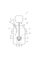
- FIG. 1 is a schematic cross-sectional view showing an example of a reaction apparatus 1 according to the first embodiment of the present invention.
- the reaction apparatus 1 includes a reaction vessel 3 in which a reaction solution is accommodated, a stirring body 13 disposed in the reaction vessel 3, and a drive for stirring the reaction solution by rotating the stirring body 13 around a rotation axis G.
- Unit 18 The reaction apparatus 1 may have an introduction part 5 into which a raw material can be introduced into the reaction vessel 3.
- the reaction vessel 3 may have a lid 4, and the introduction part 5 may be provided so as to penetrate the lid 4.
- the lid 4 may have an opening 19, and an additional introduction means may be connected to the opening 19, which is provided to replace the reaction liquid with an inert gas or the like through the opening 19. It may be done.
- FIG. The drive unit 18 is not particularly limited as long as the stirring member 13 can be rotated around the rotation axis G, and a motor or the like can be used.
- the stirrer 13 and the drive unit 18 may be connected to the shaft body 11 disposed along the rotation axis G so that the stirrer 13 can be rotated around the rotation axis G.
- the stirring body 13 has a discharge port 15 and a suction port 16 on the surface.
- the stirrer 13 has a shape in which a discharge port and a suction port connected to the discharge port via a communication path 14 provided in the base 12 are provided on the surface of the base 12 that is rotationally symmetric about the rotation axis G. I have it.
- the suction port 16 is provided at a position closer to the rotation axis G than the discharge port 15.
- the reaction liquid is stirred by generating the flow in this way.
- the reaction apparatus 1 of the present embodiment discharges the reaction liquid radially from the discharge port 15 by centrifugal force, so that the flow of the reaction liquid colliding with the wall surface of the reaction vessel 3 diffuses vertically upward and downward. In addition, not only the horizontal direction but also the vertical circulation flow is generated.
- the stirring body 13 has the above-mentioned shape, it is difficult for reaction to occur due to a collision with an object to be stirred. Moreover, since the reaction liquid smoothly flows around the stirring body 13, the generated flow is hardly disturbed.
- the reactor 1 of this embodiment can be used conveniently for both homogeneous and heterogeneous liquid phase reactions.
- the CV value of the particle size of the resin particles produced is reduced.
- the particle size distribution of the resin particles can be made more monodisperse.
- the CV value of the particle size of the resin particles can be further reduced.
- the present inventors consider the following as a reason why it is possible to produce resin particles excellent in monodispersity with respect to the particle size distribution using the reactor 1.
- the conventional reaction apparatus uses an impeller stirring body, in addition to causing unevenness in stirring as described above during the reaction, the particles in the middle of the reaction collide with the blades, and the particles are mixed. Unification and sticking to the blade occurs. Further, a shearing force is applied to the particles during the reaction by the stirring operation. As a result, the particles in the middle of the reaction do not become a single particle but aggregate and adhere to the blade as an aggregate, resulting in a decrease in yield.
- the stirrer 13 is provided with a discharge port on the surface of the convex substrate 12 that is rotationally symmetric about the rotation axis G, and the communication passage 14 provided inside the discharge port and the substrate 12. Since it has the shape which provided the inlet port connected through this, it can stir, without applying shear force to the particle
- the stirrer 13 has a shape in which a discharge port and a suction port connected to the discharge port via a communication path provided inside the substrate are provided on the surface of the convex base 12 that is rotationally symmetric about the rotation axis G.
- the material of the substrate 12 is not particularly limited, and examples thereof include metals, ceramics, silicon, and wood, and metals are particularly preferable in view of durability and ease of processing.
- the metal stainless steel is particularly preferable from the viewpoints of solvent resistance, detergency, durability, heat resistance, and the like.
- the material of the substrate 12 is preferably a fluororesin.
- the ratio of the width of the substrate 12 to the width of the reaction vessel 3 is preferably in the range of 1/10 to 4/5, more preferably 1/5 to 7/10. A range of / 3 to 3/5 is particularly preferable.
- the width of the reaction vessel 3 and the substrate 12 are different in the direction perpendicular to the rotation axis G, the width of the reaction vessel 3 indicates the width in the shortest direction, and the width of the substrate 12 indicates the width in the longest direction.
- the ratio is 1/10 or more, convection of the reaction solution tends to be performed smoothly.
- the distance with the inner wall of reaction container can fully be ensured as it is 4/5 or less, damage to reaction container 3 or the base
- substrate 12 can be prevented.
- the shape of the substrate 12 is not particularly limited as long as it is a convex shape that is rotationally symmetric about the rotation axis G, but the cross-sectional shape perpendicular to the rotation axis G is preferably a regular n-gon or a circle. n may be 6 or more, and may be 8 or more.
- the convex shape refers to a shape in which all points on a line segment connecting any two different points in the substrate 12 or on the surface are points on the substrate 12 or on the surface.
- the shape of the base 12 include a regular polyhedron, a truncated polyhedron, a regular n prism, a regular n pyramid, a sphere, an ellipsoid, a partial sphere or a partial ellipsoid obtained by cutting a part of a sphere or an ellipsoid with a plane.
- the stirrer 13 can be manufactured by forming the discharge port, the suction port, and the communication path by providing a through hole in the base 12 with a drill.
- the suction port 16 is provided at a position closer to the rotation axis G than the discharge port 15.
- the distance between the rotation axis G and the suction port 16 is the distance between the rotation axis G and the point closest to the rotation axis G among the points on the edge of the suction port 16.
- the directions of the discharge port and the suction port are not particularly limited. However, considering that the reaction liquid enters from the inlet and exits from the outlet, it is preferable that the directions are different from each other. The directions of the discharge port and the suction port are appropriately adjusted so that convection and stirring can be sufficiently performed.
- an angle ⁇ 1 formed by a straight line parallel to the center line of the communication path in a plane connecting both ends of the suction port 16 in a direction perpendicular to the rotation axis G and the vertical downward direction of the rotation axis G From the viewpoint of further reducing the centrifugal force applied to the reaction solution at the mouth 16, it is preferably 10 ° or less, more preferably 1 ° or less, and further preferably 0 °.
- An angle ⁇ 2 formed by a straight line parallel to the center line of the communication path in a plane connecting both ends of the discharge port 15 in a direction perpendicular to the rotation axis G and a vertically downward direction of the rotation axis G is a reaction liquid at the discharge port 15.
- ⁇ 2 - ⁇ 1 is preferably 1 to 179 °, more preferably 10 to 160 °, still more preferably 45 to 135 °, and most preferably 75 to 105 °.
- Examples of the cross-sectional shape perpendicular to the center line of the communication path include a circular shape and a polygonal shape, but a circular shape is preferable from the viewpoint of applying no external force to fine particle precursors such as seed particles and monomer oil droplets.
- the inner wall may have irregularities and may be a smooth surface, but a smooth surface is preferable considering that the fine particle precursor flows in the communication path.
- the minimum inner diameter (diameter) of the communication path is not particularly limited as long as it is sufficiently larger than the fine particle precursor, but is preferably 90 times or more. When the minimum inner diameter is 90 times or more, the fine particle precursor can be prevented from being clogged in the communication path.
- the stirrer 13 is not particularly limited as long as it has one or more pairs of discharge ports and suction ports, but preferably has 2 pairs, more preferably 3 or 4 pairs. By having three or four pairs, a sufficient amount of the reaction solution can be passed through the communication path. That is, the reaction liquid in the reaction vessel can be sufficiently stirred without unevenness.
- the stirring body 13 preferably has a rotationally symmetric shape about the rotation axis G including the communication path.
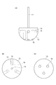
- FIGS. 2 and 3 are diagrams each showing an example of the stirring body of the present embodiment.
- FIG. 2A is a front view of an agitator formed by providing a partial spherical base 12 with three pairs of discharge ports 15 and suction ports 16. The three pairs of the discharge port 15 and the suction port 16 are communicated with each other via the communication path 14.
- 2B and 2C are a plan view of the stirring body of FIG. 2A viewed from the shaft body side and a bottom view of the stirring body viewed from the opposite side of the shaft body, respectively.
- FIG. 3 is a view showing an agitator 33 in which a pair of discharge ports 35 and a suction port 36 are provided in the cylindrical base body 12.
- the discharge port 35 and the suction port 36 are communicated with each other by a communication path 34.
- the shape of the substrate 12 is a cylinder or a regular n prism, if the shaft body 31 and the suction port 36 are concentric, the suction direction is always constant, so that the reaction liquid can be stirred more uniformly.
- the communication path may communicate a pair of discharge ports and suction ports, but may communicate a plurality of discharge ports and a plurality of suction ports.
- the shapes of the suction port and the discharge port are not particularly limited, but can be, for example, circular.
- the material of the reaction vessel 3 is not particularly limited, and examples thereof include glass, metal, wood, plastic, ceramic, etc. It goes without saying that the vessel material is selected according to the conditions for driving the reaction performed in the reaction vessel. . For example, when the reaction is performed by heat, a glass or metal container is preferably used. When the reaction is performed by light, it is preferable to use a transparent glass or plastic container.
- the shape of the container surface and the inner wall is not particularly limited, but a smooth surface is preferable because the flow in the container is not disturbed and uniform stirring is possible. Further, when the resin particles are manufactured, since an extra external force is not applied to the fine particle precursor, coalescence due to collision can be reduced.
- the shape of the reaction vessel 3 is not particularly limited, but considering that the reaction solution is uniformly stirred in the reaction vessel 3, the shape of the inner wall in contact with the reaction solution is preferably a continuous curved surface having no acute angle.
- the outer shape of the reaction vessel 3 is more preferably circular when observed from a cross section perpendicular to the rotation axis G.
- the shape of the wall surface of the reaction vessel 3 may be a flat surface or a curved surface. However, considering that the reaction liquid is uniformly stirred in the reaction vessel 3, the bottom surface of the vessel is preferably a curved surface.
- the reaction is performed in the reaction liquid by introducing the raw materials necessary for performing the target liquid phase reaction from the introduction unit 5.
- a raw material may be, for example, a part of a reactant in a target liquid phase reaction such as a monomer, an oligomer, or a fine particle precursor such as a seed particle used in seed polymerization. These may be introduced in the form of solutions or dispersions.
- the monomer is introduced as monomer oil droplets emulsified with ultrasonic waves or the like, the diameter of the monomer oil droplet is particularly preferably 10 nm to 10 ⁇ m.
- the average particle size of the seed particles is particularly preferably 20 nm to 50 ⁇ m. When the average particle size of the seed particles is 20 nm to 50 ⁇ m or more, the average particle size of the seed particles after swelling is easily made uniform.
- a solvent contained in the reaction solution water, an organic solvent, a mixture of water and an organic solvent, or the like can be freely selected according to circumstances. The ratio of the component solvents in the mixture is also arbitrary.
- the specific configuration of the introduction unit 5 is not particularly limited, and examples include a funnel, a rubber hose, a silicon tube, a polytetrafluoroethylene tube, a plastic pipe, a metal pipe, and a microtube pump.
- the introduction unit 5 is preferably configured to introduce the raw material to the wall surface side of the reaction vessel 3 relative to the stirring body 13 as viewed from the rotation axis G, that is, to a position farther from the stirring body 13 as viewed from the rotation axis G. .
- the raw material can be quickly put on the convection generated by the rotation of the stirring member 13, and thus the reaction in the reaction liquid can be performed more uniformly.
- the introduction port for introducing the raw material from the introduction unit 5 into the reaction vessel 3 is viewed from the rotation axis G with respect to the wall surface side of the reaction vessel 3 from the stirring body 13, that is, It is preferable to face the direction away from the stirring body 13 when viewed from the rotation axis G.
- the reaction apparatus 1 of this embodiment is suitable for the production of resin particles.
- the average particle diameter of the resin particles to be produced is preferably 100 ⁇ m or less, more preferably 65 ⁇ m or less, further preferably 30 ⁇ m or less, and particularly preferably 20 ⁇ m or less.
- the average particle diameter of the resin particles is preferably 1 ⁇ m or more, more preferably 1.5 ⁇ m or more, and further preferably 1.75 ⁇ m or more from the viewpoint of preventing aggregation of the resin particles.
- Examples of the method for synthesizing fine particles having high monodispersibility include emulsion polymerization, soap-free emulsion polymerization, seed polymerization and the like. Among these, seed polymerization is most preferable because monodisperse fine particles are easily synthesized.
- the CV value of the particle size (diameter) of the resin particles is preferably 15% or less.
- the performance of the resin particles in various applications tends to be improved.
- the connection reliability when the resin particles are used for the conductive particles constituting the anisotropic conductive material tends to be improved, or the quantitativeness when the resin particles are used for the biopsy element tends to be improved.
- the CV value of the particle size of the resin particles is more preferably 10% or less, further preferably 5% or less, and still more preferably 4% or less.
- the CV value (coefficient of variation) of the particle diameter means a ratio of the standard deviation of the particle diameter to the average value of the particle diameter expressed as a percentage.
- the average particle diameter of the resin particles and the CV value of the particle diameter can be determined by the following measurement method. 1) Disperse particles in water using an ultrasonic dispersion device to prepare a dispersion containing 1% by mass of particles. 2) Using a wet flow type particle size / shape analyzer (manufactured by Sysmex Corporation), an image of about 100,000 particles in the dispersion is analyzed, and the average particle size and the CV value of the particle size are calculated.
- the method for producing resin particles of the present embodiment is a method for producing resin particles by carrying out a polymerization reaction while stirring an emulsion containing seed particles and a monomer in a reaction vessel, and around the rotation axis G in the reaction vessel.
- the emulsion is stirred by rotating the stirring body.
- the resin particles of the present embodiment are particles obtained by swelling seed particles in an emulsion containing a monomer and then seed-polymerizing the seed particles and the monomer.
- the emulsion may contain a polymer monomer and an aqueous medium constituting the target resin particles. Moreover, the emulsion may contain the surfactant or dispersing agent shown separately.
- the reaction time can be changed depending on the type of seed particles or monomers. For example, in consideration of swelling of seed particles with monomers in seed polymerization, the reaction time is preferably in the range of 0.1 to 72 hours. More preferably in the range of 2 to 48 hours, most preferably in the range of 0.5 to 30 hours. When the reaction time is 0.1 hours or longer, poor formation of resin particles can be suppressed, and when the reaction time is 72 hours or shorter, aggregation and coalescence of the formed particles tend to be suppressed.
- fine particles can be obtained stably using temperature.
- Examples thereof include a polymerization reaction.
- the polymerization temperature can be changed depending on the type of the reactive monomer, but is preferably in the range of 30 to 200 ° C, more preferably in the range of 30 to 175 ° C, and in the range of 30 to 150 ° C. Most preferred. When the temperature is 30 ° C. or higher, the polymerization of the reactive monomer tends to proceed sufficiently, and when it is 200 ° C. or lower, the solvent used in the reaction is difficult to evaporate and a sufficient amount of solvent tends to be secured.
- the seed particles may be particles obtained by polymerizing any one of a monomer having an active hydrogen group and a (meth) acrylic acid ester, or particles obtained by copolymerizing these monomers.
- the seed particles may be particles obtained by copolymerizing the monomer having the active hydrogen group and the (meth) acrylic acid ester with other monomers copolymerizable with these monomers.
- the seed particles can be synthesized by a known method such as an emulsion polymerization method, a soap-free emulsion polymerization method, or a dispersion polymerization method.
- the interaction between the seed particles and the polymer synthesized from the monomer containing the di (meth) acrylate compound after seed polymerization is increased. It is preferable because it is excellent in compression recovery rate even during heating.
- Examples of the active hydrogen group include a hydroxyl group, a carboxyl group, and an amide group.
- carboxyl group-containing monomer examples include unsaturated carboxylic acids such as acrylic acid, methacrylic acid, crotonic acid, cinnamic acid, itaconic acid, maleic acid and fumaric acid, itaconic acid monoalkyl esters such as itaconic acid monobutyl, and maleic acid.
- unsaturated carboxylic acids such as acrylic acid, methacrylic acid, crotonic acid, cinnamic acid, itaconic acid, maleic acid and fumaric acid
- itaconic acid monoalkyl esters such as itaconic acid monobutyl
- maleic acid examples include monoalkyl maleic esters such as monobutyl, vinyl group-containing aromatic carboxylic acids such as vinyl benzoic acid, and salts thereof.
- hydroxyl group-containing monomer examples include 4- (hydroxymethyl) cyclohexylmethyl (meth) acrylate, 2-hydroxyethyl (meth) acrylate, 2-hydroxypropyl (meth) acrylate, 3-hydroxypropyl (meth) acrylate, 4 -Hydroxyl-containing (meth) acrylic monomers such as hydroxybutyl (meth) acrylate; (poly) alkylene glycol (meth) acrylic such as (poly) ethylene glycol mono (meth) acrylate and (poly) propylene glycol mono (meth) acrylate Monomers; hydroxyalkyl vinyl ether monomers such as hydroxyethyl vinyl ether and hydroxybutyl vinyl ether; and hydroxyl-containing allyl monomers such as allyl alcohol and 2-hydroxyethyl allyl ether Such as Ma and the like.
- amide group-containing monomers examples include (meth) acrylamide, ⁇ -ethyl (meth) acrylamide, N-methyl (meth) acrylamide, N-butoxymethyl (meth) acrylamide, diacetone (meth) acrylamide, and N, N-dimethyl.
- These monomers having an active hydrogen group can be used singly or in combination of two or more.
- the monomer having an active hydrogen group a monomer capable of imparting an active hydrogen group can also be used.
- a monomer which can provide an active hydrogen group the monomer which has a glycidyl group, an epoxy group, or an isocyanate group is mentioned, for example.
- the copolymerization ratio of the monomer having an active hydrogen group in the copolymer is 50% by mass or less based on the total amount of monomers constituting the seed particles. It is preferably 45% by mass or less, and more preferably 40% by mass or less.
- the copolymerization ratio of the monomer having an active hydrogen group is preferably 0.1% by mass or more, and more preferably 0.3% by mass or more.
- the seed particles have a (meth) acrylic acid ester as a monomer unit
- the seed particles are easily compatible with the di (meth) acrylate compound, so that the breaking strength tends to be improved as compared with the case where polystyrene is used as the seed particles. Therefore, it is preferable.
- (meth) acrylic acid esters examples include methyl acrylate, ethyl acrylate, propyl acrylate, n-butyl acrylate, isobutyl acrylate, hexyl acrylate, 2-ethylhexyl acrylate, n-octyl acrylate, and acrylic.
- (meth) acrylic acid esters can be used alone or in combination of two or more.
- a (meth) acrylic acid ester having a linear alkyl group is used, the compatibility with the di (meth) acrylate compound is improved.
- the weight average molecular weight (Mw) of the seed particles is to improve the absorption capacity of the monomer of the seed particles when producing resin particles, or from the viewpoint of preventing the mechanical strength from being reduced by phase separation from the monomer to be absorbed. It is preferably 50000 or less, and more preferably 30000 or less. Further, from the viewpoint of making the particle size more uniform, the lower limit of Mw of the seed particles is preferably 3000 or more, and more preferably 5000 or more.
- regulated by this specification is the value measured using the analytical curve by a standard polystyrene by the gel permeation chromatography method (GPC).
- the average particle size of the seed particles can be adjusted according to the design particle size of the obtained resin particles.
- the average particle size of the seed particles is preferably from 0.1 to 30 ⁇ m, more preferably from 0.1 to 25 ⁇ m, still more preferably from 0.1 to 20 ⁇ m.
- the CV value which is the coefficient of variation of the particle size (diameter) of the seed particles, is preferably 10% or less, more preferably 7% or less, and more preferably 5% or less from the viewpoint of further improving the uniformity of the resin particles obtained. Is more preferable.
- the average particle size of the seed particles and the CV value of the particle size can be calculated by observing 100 seed particles of interest with a scanning electron microscope (SEM) and measuring the particle size. It is also possible to calculate from the particle size measured using a particle size measuring device such as a meter (manufactured by Nikkiso Co., Ltd.).
- the final particle size of the resin particles is adjusted to 3 to 100 times the average particle size of the seed particles. It is preferably 3 to 70 times, more preferably 4 to 60 times.
- the copolymerization ratio of the monomer having an active hydrogen group in the copolymer is 40% by mass or less, the monomer can be efficiently absorbed by the seed particle when the seed particle is added to the emulsion.
- the seed particles have a weight average molecular weight of 3,000 to 50,000, the monomer is easily absorbed when the seed particles are swollen in the emulsion.
- the resin particles are obtained by swelling the seed particles in an emulsion containing the monomer and then seed polymerizing the monomer.
- the seed polymerization method can be performed with reference to a known method. A general method of the seed polymerization method will be described below, but is not limited to this method.
- seed particles are added to an emulsion containing a monomer and an aqueous medium.
- the seed particles may be added directly to the emulsion or may be added in a form in which the seed particles are dispersed in an aqueous dispersion.
- the emulsion can be prepared by a known method.
- an emulsion can be obtained by adding a monomer to an aqueous medium and dispersing the monomer in an aqueous medium using a fine emulsifier such as a homogenizer, an ultrasonic processor, or a nanomizer.
- the emulsion may contain a polymerization initiator as necessary.
- the polymerization initiator may be mixed in advance with the monomer and then dispersed in an aqueous medium, or a mixture of a polymerization initiator and a monomer separately dispersed in an aqueous medium may be mixed.
- the diameter of the monomer droplets in the obtained emulsion is smaller than the average particle diameter of the seed particles, the monomer is more easily absorbed into the seed particles.
- the seed particles After adding the seed particles to the emulsion, the seed particles are swollen and the seed particles absorb the monomer. This absorption can usually be performed by stirring the emulsion after addition of seed particles at room temperature for 1 to 24 hours. Further, the absorption of the monomer can be promoted by heating the emulsion to about 30 to 50 ° C.
- the addition amount of the seed particles can be appropriately adjusted depending on, for example, the desired particle diameter, and is not particularly limited. However, from the viewpoint of easily expanding the seed particles uniformly, the total amount of monomers in the emulsion is 100 parts by mass. The amount is preferably 0.0001 to 10 parts by mass, and more preferably 0.0003 to 8 parts by mass.
- the seed particles swell due to the absorption of the monomer.
- the mixing ratio of the monomer to the seed particle is reduced, the increase in the particle size of the resin particle produced by the seed polymerization of the monomer is reduced, and the productivity of the resin particle tends to be lowered.
- the mixing ratio of the monomer is increased, the monomer may not be absorbed by the seed particles, and the monomer may be uniquely suspension-polymerized in the aqueous medium, and particles other than the target particle size may be generated.
- the completion of monomer absorption can be determined by observing seed particles using an optical microscope and confirming the increase in particle size.
- the emulsion according to this embodiment preferably contains a di (meth) acrylate compound as a monomer.
- the di (meth) acrylate compound is not particularly limited as long as it is a bifunctional monomer having two (meth) acryloyl groups.
- alkanediol di (meth) acrylate can be included.
- the alkanediol di (meth) acrylate preferably contains a di (meth) acrylate compound represented by the following formula (1).
- the content of the di (meth) acrylate compound represented by the formula (1) is preferably 80 mol% or more, more preferably 85 mol% or more, and more preferably 90 mol% or more based on the total amount of monomers. Is more preferable.
- each of R 1 and R 2 independently represents a hydrogen atom or a methyl group
- L 1 represents an alkylene group having 4 to 12 carbon atoms
- the alkylene group may be linear, branched or cyclic.
- Examples of the di (meth) acrylate compound represented by the formula (1) include 1,3-butanediol di (meth) acrylate, 1,4-butanediol di (meth) acrylate, and 1,5-pentanediol diester.
- alkanediol di (meth) acrylates such as diol di (meth) acrylate, 1,9-nonanediol di (meth) acrylate, 1,10-decanediol di (meth) acrylate, and neopentyl glycol di (meth) acrylate. It is done.
- the monomer other polyfunctional monomers and / or monofunctional monomers can be used together with the di (meth) acrylate compound.
- multifunctional monomers examples include divinyl compounds such as divinylbenzene, divinylbiphenyl, divinylnaphthalene; (poly) ethylene glycol di (meth) acrylate, (poly) propylene glycol di (meth) acrylate, and (poly) tetramethylene glycol.
- (Poly) alkylene glycol-based di (meth) acrylates such as di (meth) acrylate; trimethylolpropane tri (meth) acrylate, tetramethylolmethane tri (meth) acrylate, tetramethylolpropane tetra (meth) acrylate, pentaerythritol tri ( 3 or more functional groups such as (meth) acrylate, 1,1,1-trishydroxymethylethane tri (meth) acrylate, 1,1,1-trishydroxymethylpropane tri (meth) acrylate (Meth) acrylate; ethoxylated bisphenol A di (meth) acrylate, propoxylated ethoxylated bisphenol A di (meth) acrylate, tricyclodecane dimethanol di (meth) acrylate, 1,1,1-trishydroxymethylethane Di (meth) acrylates such as di (meth) acrylate and ethoxylated
- NK ester (A-TMPT-6P0, A-TMPT-3E0, A-TMM-3LMN, A-GLY series, A-9300, AD-TMP, AD-TMP, manufactured by Shin-Nakamura Chemical Co., Ltd. -4CL, ATM-4E, A-DPH) and the like are commercially available.
- These polyfunctional monomers may be used alone or in combination of two or more.
- Examples of the monofunctional monomer include styrene, o-methylstyrene, m-methylstyrene, p-methylstyrene, ⁇ -methylstyrene, o-ethylstyrene, m-ethylstyrene, p-ethylstyrene, 2,4- Dimethyl styrene, pn-butyl styrene, pt-butyl styrene, pn-hexyl styrene, pn-octyl styrene, pn-nonyl styrene, pn-decyl styrene, pn-dodecyl Styrene such as styrene, p-methoxystyrene, p-phenylstyrene, p-chlorostyrene, 3,4
- aqueous medium examples include water or a mixed medium of water and a water-soluble solvent (for example, lower alcohol).
- the aqueous medium contains a surfactant.
- the surfactant any of anionic, cationic, nonionic and zwitterionic surfactants can be used.
- anionic surfactant examples include fatty acid oils such as sodium oleate and castor oil potassium, alkyl sulfate salts such as sodium lauryl sulfate and ammonium lauryl sulfate, alkylbenzene sulfonates such as sodium dodecylbenzenesulfonate, and alkylnaphthalene sulfone.
- Acid salts alkane sulfonates, dialkyl sulfosuccinates such as sodium dioctyl sulfosuccinate, alkenyl succinates (dipotassium salts), alkyl phosphate esters, naphthalene sulfonate formalin condensates, polyoxyethylene alkylphenyl ether sulfates Salt, polyoxyethylene alkyl ether sulfate such as sodium polyoxyethylene lauryl ether sulfate, polyoxyethylene alkyl sulfate ester salt, dodecyl sulfate Such as ethanol, and the like.
- cationic surfactant examples include alkylamine salts such as laurylamine acetate and stearylamine acetate, and quaternary ammonium salts such as lauryltrimethylammonium chloride.
- Nonionic surfactants include, for example, hydrocarbon nonionic surfactants such as polyethylene glycol alkyl ethers, polyethylene glycol alkyl aryl ethers, polyethylene glycol esters, polyethylene glycol sorbitan esters, polyalkylene glycol alkylamines, or amides.
- hydrocarbon nonionic surfactants such as polyethylene glycol alkyl ethers, polyethylene glycol alkyl aryl ethers, polyethylene glycol esters, polyethylene glycol sorbitan esters, polyalkylene glycol alkylamines, or amides.
- Agents polyether-modified silicone nonionic surfactants such as silicon polyethylene oxide adducts and polypropylene oxide adducts, and fluorine nonionic surfactants such as perfluoroalkyl glycols.
- zwitterionic surfactants include hydrocarbon surfactants such as lauryl dimethylamine oxide, phosphate ester surfactants, and phosphite ester surfactants.
- Surfactant may be used alone or in combination of two or more.
- an anionic surfactant is preferable from the viewpoint of dispersion stability during polymerization of the monomer.
- polymerization initiator examples include benzoyl peroxide, lauroyl peroxide, orthochlorobenzoyl peroxide, orthomethoxybenzoyl peroxide, 3,5,5-trimethylhexanoyl peroxide, and t-butyl peroxide.
- Organic peroxides such as oxy-2-ethylhexanoate and di-t-butyl peroxide; 2,2′-azobisisobutyronitrile, 1,1′-azobiscyclohexanecarbonitrile, 2,2 ′ -Azo compounds such as azobis (2,4-dimethylvaleronitrile).
- the polymerization initiator is preferably used in the range of 0.1 to 7.0 parts by mass with respect to 100 parts by mass of the monomer.
- the monomer absorbed in the seed particles is polymerized to obtain monodisperse resin particles.
- the polymerization temperature can be appropriately selected according to the type of monomer and polymerization initiator.
- the polymerization temperature is preferably 25 to 110 ° C, more preferably 50 to 100 ° C.
- the polymerization reaction is preferably carried out at an elevated temperature after the seed particles are sufficiently swollen and the monomer and optionally the polymerization initiator are completely absorbed.
- the aqueous medium is removed from the polymerization solution by centrifugation as necessary, the resin particles are isolated by washing with water and a solvent, and then drying.
- a dispersion stabilizer may be added to the emulsion.
- shear acting on the resin particles during polymerization Since the force is small, it is not necessary to use a dispersion stabilizer.
- a dispersion stabilizer is not used, it is preferable because a step of removing the dispersion stabilizer from the produced resin particles can be omitted.
- dispersion stabilizer examples include polyvinyl alcohol, polycarboxylic acid, celluloses (such as hydroxyethyl cellulose and carboxymethyl cellulose), and polyvinyl pyrrolidone.
- An inorganic water-soluble polymer compound such as sodium tripolyphosphate can also be used in combination.
- polyvinyl alcohol or polyvinyl pyrrolidone is preferred.
- the addition amount of the dispersion stabilizer is preferably 1 to 10 parts by mass with respect to 100 parts by mass of the monomer.
- water-soluble polymerization inhibitors such as nitrites, sulfites, hydroquinones, ascorbic acids, water-soluble vitamin Bs, citric acid, and polyphenols are used. It may be used.
- the electroconductive particle of this embodiment has the said resin particle and the metal film formed on the surface of this resin particle.
- FIG. 4 is a schematic cross-sectional view showing conductive particles according to the present embodiment. As shown in FIG. 4, the conductive particles 40 include resin particles 41 and a metal coating (metal layer) 42 that covers the surfaces of the resin particles 41.
- metal which comprises the metal layer 42 For example, gold
- the metal layer 2 preferably contains nickel, copper, gold, or a tin-silver alloy.
- the method for forming the metal layer 42 on the surface of the resin particles 41 is not particularly limited.
- Examples of the method for forming the metal layer 42 include an electroless plating method, an electroplating method, a physical vapor deposition method, and a method of applying a paste containing metal powder to the surface of the resin particles 41.
- As physical vapor deposition vacuum vapor deposition, ion plating, or ion sputtering can be used.
- As a method of forming the metal layer 42 an electroless plating method is preferable.
- the metal layer 42 may be a single layer or a plurality of metal layers in which two or more layers are laminated. From the viewpoint of reducing the connection resistance between the electrodes, the surface of the conductive particles 40 (the outermost layer of the metal layer 42) is preferably a gold layer, a palladium layer, or a tin-silver alloy layer.
- the thickness of the metal layer 42 is preferably 0.02 to 1 ⁇ m, and more preferably 0.02 to 0.5 ⁇ m. If the thickness of the metal layer 42 is 0.02 ⁇ m or more, good conductivity is easily developed, and if it is 1 ⁇ m or less, the conductive particles are easily deformed at the time of connection.
- the thickness of the metal layer 2 can be calculated
- the average particle diameter of the conductive particles 40 is preferably 1.02 to 101 ⁇ m, more preferably 1.5 to 80 ⁇ m, and further preferably 2 to 67 ⁇ m.
- the CV value of the particle diameter of the conductive particles 40 is preferably 10% or less, more preferably 7% or less, and further preferably 5% or less. When the CV value of the conductive particles 40 is 10% or less, the electrical connection reliability can be further increased.
- the average particle diameter and the CV value of the particle diameter of the conductive particles 40 can be measured by the same method as that for the resin particles 41.
- the anisotropic conductive material of the present embodiment includes the conductive particles and a binder resin.
- FIG. 5 is a schematic cross-sectional view showing the anisotropic conductive material according to the present embodiment.
- the anisotropic conductive material 60 includes an insulating binder resin 50 and conductive particles 40 dispersed in the binder resin 50.
- thermosetting resin composition containing a thermosetting resin, a curing agent, a film-forming polymer, or the like can be used.
- the thermosetting resin is not particularly limited, but an epoxy resin is preferably used from the viewpoint of heat resistance.
- an epoxy resin is preferably used from the viewpoint of heat resistance.
- the epoxy resin various epoxy compounds having two or more glycidyl groups in the molecule can be used.
- bisphenol type epoxy resin, novolac type epoxy resin, naphthalene type epoxy resin, biphenyl type epoxy resin, alicyclic ring Formula type epoxy resins, glycidyl amine compounds, glycidyl ether compounds, and glycidyl ester compounds may be mentioned.
- the epoxy resin impurity ions (Na +, Cl -, etc.), the hydrolyzable chlorine and the like use a high-purity product was reduced to 300ppm or less, it is easy to prevent electromigration.
- the curing agent is not particularly limited, but a latent curing agent can be used.
- the latent curing agent include imidazole compounds, hydrazide compounds, boron trifluoride-amine complexes, sulfonium salts, amine imides, polyamine salts, and dicyandiamide.
- the film-forming polymer is not particularly limited as long as the anisotropic conductive material can be formed into a film shape.
- the film-forming polymer include thermoplastic resins such as phenoxy resin, polyester resin, and polyamide resin.
- butadiene rubber, acrylic rubber, styrene-butadiene rubber, silicone rubber, or the like can be mixed in order to reduce stress after adhesion or to improve adhesion.
- the binder resin 50 can be blended with an inorganic filler.
- an inorganic filler for example, a filler made of silica, magnesia, bentonite, smectite, alumina, or boron nitride can be used.
- the binder resin 50 may be a photocurable resin composition containing a photopolymerization initiator such as a radical polymerizable resin and an organic peroxide instead of the thermosetting resin and the curing agent.
- a photopolymerization initiator such as a radical polymerizable resin and an organic peroxide
- the anisotropic conductive material 60 can be manufactured as follows, for example. First, a binder resin 50 is prepared by dissolving or dispersing a thermosetting resin composition containing an epoxy resin, an acrylic rubber, a latent curing agent, and a film-forming polymer in an organic solvent as necessary. Subsequently, the liquid anisotropic conductive material 60 is produced by dispersing the conductive particles 40 in the binder resin 50.
- the organic solvent those capable of dissolving the resin component and having a boiling point of 50 to 150 ° C. at normal pressure are preferable.
- the liquid anisotropic conductive material 60 can be used as it is for connecting circuit members, but can be used after being formed into a film.
- the film-like anisotropic conductive material 60 is formed by applying the liquid anisotropic conductive material 60 on the release film, removing the organic solvent below the activation temperature of the curing agent, and then peeling the film from the release film. Can be produced.
- a resin film such as a fluororesin film, a polyethylene terephthalate film, and a polyolefin film is preferably used. If the anisotropic conductive material 60 is used in the form of a film, it is convenient from the viewpoint of handleability.
- the thickness of the film-like anisotropic conductive material 60 is relatively determined in consideration of the average particle diameter of the conductive particles 40 and the characteristics of the anisotropic conductive material 60, and is preferably 1 to 100 ⁇ m. More preferably, it is ⁇ 50 ⁇ m. If the anisotropic conductive material 60 has a thickness of 1 ⁇ m or more, sufficient adhesion tends to be obtained, and if it is 100 ⁇ m or less, sufficient connection reliability can be obtained with a small amount of conductive particles 40 in order to obtain conductivity. There is a tendency.
- the circuit member connection structure 48 includes a first circuit member in which the first circuit electrode 45 is formed on the main surface of the first circuit board 44, and the main circuit board 46.
- a second circuit member having a second circuit electrode 47 formed on the surface; and a connecting portion interposed between the first circuit member and the second circuit member.
- the second circuit member is disposed so that the second circuit electrode faces the first circuit electrode, and the connection portion includes the conductive particles according to the present embodiment.
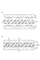
- FIG. 6 is a schematic cross-sectional view showing a method for producing a circuit member connection structure using the anisotropic conductive material according to the present embodiment.
- a first circuit board 44 on which a first circuit electrode 45 is formed and a second circuit board 46 on which a second circuit electrode 47 is formed are prepared. Then, the anisotropic conductive material 60 is disposed therebetween. At this time, the position is adjusted so that the first circuit electrode 45 and the second circuit electrode 47 face each other. Thereafter, the first circuit board 44 and the second circuit board 46 are stacked while being heated under pressure in a direction in which the first circuit electrode 45 and the second circuit electrode 47 face each other, as shown in FIG.
- the connection structure 10 shown in b) is obtained.
- the connection structure 10 is electrically connected by a cured product of the anisotropic conductive material 60.
- Examples of the first circuit board 44 and the second circuit board 46 include a glass substrate, a tape substrate such as polyimide, a bare chip such as a driver IC, and a rigid package substrate.
- FIG. 7 is a schematic cross-sectional view showing an example of the reaction apparatus 21 according to the second embodiment of the present invention.
- the reaction device 21 includes a reaction vessel 23 in which a reaction solution is stored, a stirring body 13 disposed in the reaction vessel 23, and a drive for stirring the reaction solution by rotating the stirring body 13 around the rotation axis G. Unit 18.
- the stirring body 13 the same thing as the stirring body 13 in the above-described reaction apparatus 1 can be used.
- the stirring body 13 is provided on the bottom side of the reaction vessel 23 in the direction of the rotation axis G. Yes.
- the reaction device 21 may have the introduction part 5 and the lid 4.
- the introduction unit 5 the lid 4, and the driving unit 18, the same ones as those of the above-described reaction apparatus 1 can be used.
- the reaction vessel 23 has a first wall surface 3a for guiding the flow of the reaction liquid stirred in the reaction vessel 23 in the direction below the reaction vessel 23 and in the direction approaching the rotation axis G.
- the reaction vessel used in the conventional reaction apparatus is composed of a side surface parallel to the rotation axis G and a flat bottom, the wall of the reaction vessel moves the reaction solution below the reaction vessel and approaches the rotation axis G. As a result, a region where the flow of the reaction liquid is weak is formed in the reaction vessel, and the entire lower side of the reaction vessel cannot be stirred smoothly.
- the reaction vessel 23 of the present embodiment has the above-described first wall surface, when the stirring body 13 is rotated, the reaction liquid discharged from the discharge port 15 is stirred along the first wall surface 3a. It is guided in a direction directly below 13. The flow of the reaction liquid guided in the direction directly below the stirring body 13 is sucked up into the suction port 16 provided on the bottom side of the stirring body 13, so that the reaction liquid is smoothly squeezed in the reaction vessel 23. A circulating flow can be generated.
- the reaction apparatus 21 of this embodiment can stir a reaction liquid more smoothly than the conventional reaction apparatus, when manufacturing a resin particle, the CV value of the particle size of a resin particle is made small. can do.
- the conventional reaction apparatus as described above, a region having a weak flow is formed, and thus solids such as resin particles in the course of synthesis are precipitated by gravity and deposited on the bottom of the reaction vessel.
- solids such as resin particles in the course of synthesis are precipitated by gravity and deposited on the bottom of the reaction vessel.
- seed particles accumulate on the bottom of the reaction vessel and agglomerate, leading to a decrease in yield and an increase in the CV value of the resulting resin particles.
- the solid matter dispersed in the reaction solution rides on a flow guided in the direction below the reaction vessel 23 and in the direction approaching the rotation axis G, and is guided in the direction directly below the stirring body 13.
- the reactor 21 of the present embodiment can be suitably used for producing resin particles, and is particularly suitable for seed polymerization.
- the first wall surface 3a preferably reaches the lowest position of the reaction vessel 23 while reducing the area of the region surrounded by the wall surface of the reaction vessel 23 in a cross section perpendicular to the rotation axis G, and the reaction proceeds while the diameter is reduced. It is more preferable to reach the lowest position of the container 23.
- the diameter reduction means that the shape of the region surrounded by the wall surface of the reaction vessel 23 in a vertical section is substantially circular, and the diameter of the circle is the direction of the lowest position of the reaction vessel 23 along the rotation axis G. It means that it gets smaller as it goes to.
- Specific examples of the shape of the reaction vessel 23 include a round bottom and an eggplant type.
- the reaction vessel 23 may have a second wall surface 3b located above the first wall surface 3a.
- the second wall surface 3 b guides the flow of the reaction liquid stirred in the reaction vessel 23 in a direction below the reaction vessel 23 and away from the rotation axis G.
- the flow of the reaction solution can be guided more smoothly below the reaction vessel 23 and in the direction approaching the rotation axis G.
- Resin particles can be produced in the same manner as in the first embodiment using the reactor 21 of the present embodiment. Moreover, similarly to 1st Embodiment, an electroconductive particle, an anisotropic conductive material, and a connection structure can be manufactured using the said resin particle.
- Examples A1 to 10 Using the reaction vessel shown in FIG. 1, 5.0 g (seed particle 0.9 g) of the seed particle dispersion of Synthesis Example 1 is added to the above emulsion and the reaction vessel is more than the stirring body when the introduction port is viewed from the rotation axis. After stirring for 12 hours at room temperature, polymerization was performed at 80 ° C. for 8 hours using a stirrer having an inner diameter of the communication path of 200 ⁇ m to synthesize resin particles. Table 1 shows the relationship between the shape of the stirrer and the number of communication paths, and the result of synthesizing the resin particles in each example.
- Example A11 A monomer in which 1.33 g of benzoyl peroxide is dissolved in 18 g of 1,4-butanediol diacrylate (BDDA) is mixed with 295 g of ion-exchanged water in which 3.0 g of triethanol dodecyl sulfate is dissolved, and treated with an ultrasonic homogenizer for 10 minutes. Thus, an emulsion was prepared.
- BDDA 1,4-butanediol diacrylate
- Example A12 Resin particles were obtained in the same manner as in Example A9, except that the amount of seed particle dispersion added in Synthesis Example 1 was changed to 0.6 g (seed particles 0.1 g) and an agitator having an inner diameter of the communication path of 400 ⁇ m was used. Was synthesized.
- Example A13 Resin particles were obtained in the same manner as in Example A9, except that the amount of seed particle dispersion added in Synthesis Example 1 was changed to 0.2 g (seed particles 0.03 g) and an agitator having an internal diameter of the communication path of 600 ⁇ m was used. Was synthesized.
- Example A14 Resin particles were obtained in the same manner as in Example A9, except that the amount of seed particle dispersion added in Synthesis Example 1 was changed to 0.07 g (seed particles 0.01 g) and an agitator having an internal diameter of the communication path of 800 ⁇ m was used. Was synthesized.
- Example A15 Same as Example A9, except that the amount of seed particle dispersion added in Synthesis Example 1 was changed to 0.04 g (seed particles 0.007 g), and a stirrer having an internal diameter of 1000 ⁇ m (1 mm) was used. Thus, resin particles were synthesized.
- Example A1 Resin particles were synthesized in the same manner as in Example A11 except that a disk turbine having six blades was used instead of the agitator and a baffle was mounted in the container.
- the particle diameters of the resin particles obtained in each Example and Comparative Example were measured with a wet flow type particle diameter / shape analyzer (manufactured by Sysmex Corporation), and the CV values of the average particle diameter and the particle diameter were calculated. The results are shown in Tables 1 and 2.
- a nickel layer having a thickness of 0.2 ⁇ m was formed on each of the resin particle surfaces obtained in Examples A11 to A15 and Comparative Example A1 by an electroless plating method, and a palladium layer having a thickness of 0.04 ⁇ m was formed outside the nickel layer. Thus, conductive particles A11 to A16 were produced.
- anisotropic conductive material was produced using the conductive particles A11 to A16 as follows.
- phenoxy resin (trade name “PKHC” manufactured by Union Carbide), acrylic rubber (copolymer of butyl acrylate, ethyl acrylate, acrylonitrile and glycidyl methacrylate, copolymerization ratio (mass) 40/30/30/3, Mw 850,000) 18 parts by mass and epoxy resin (Mitsubishi Chemical Corporation, trade name “YL-983U”) 15 parts by mass in a solution of 10 parts by mass of ethyl acetate in a cationic curing agent (Sanshin Chemical Co., Ltd.) 2 parts by mass of a product name “SI-60” manufactured by company was added to prepare a thermosetting resin composition.
- PKHC phenoxy resin
- acrylic rubber copolymer of butyl acrylate, ethyl acrylate, acrylonitrile and glycidyl methacrylate, copolymerization ratio (mass) 40/30/30/3, Mw 850,000
- epoxy resin Mitsubishi Chemical Corporation
- an ethyl acetate dispersion of 10 parts by mass of a silica filler (manufactured by Nippon Aerosil Co., Ltd., trade name “Aerosil R805”) is added to the thermosetting resin composition and mixed, and then 20 parts by mass of conductive particles. And 10 mass parts of ethyl acetate was added, ultrasonic dispersion was performed, and the liquid anisotropic conductive material was produced.
- a liquid anisotropic conductive material was applied on a silicone-treated polyethylene terephthalate film (thickness 40 ⁇ m, hereinafter referred to as “PET film”) with a roll coater and dried at 80 ° C. for 5 minutes to form a film having a thickness of 20 ⁇ m.
- PET film silicone-treated polyethylene terephthalate film
- An anisotropic conductive material was produced.
- connection structure Using the produced film-like anisotropic conductive material, a chip (1.7 mm ⁇ 17 mm, thickness: 0.5 mm) with gold bumps (area: 30 ⁇ m ⁇ 90 ⁇ m, space 10 ⁇ m, height: 15 ⁇ m, number of bumps: 362) Then, thermocompression bonding with an AlNd film-attached glass substrate (Geomatec, thickness: 0.7 mm) was performed as follows to produce a connection structure.
- the surface opposite to the surface provided with the PET film of the film-like anisotropic conductive material cut into a predetermined size (2 mm ⁇ 19 mm) is placed on the surface on which the AlNd film of the glass substrate with the AlNd film is formed. °C, 0.98MPa (10kgf / cm 2 ), was affixed by five seconds and. Thereafter, the PET film was peeled off and heated and pressurized under the conditions of 170 ° C., 70 MPa, and 5 seconds through an anisotropic conductive material to obtain a mounting sample (connection structure).
- the resin particles synthesized by the manufacturing method of the present embodiment have high monodispersity. Moreover, it was confirmed that a connection structure with little indentation variation can be produced by using conductive particles formed using the resin particles.
- Example B1 A monomer in which 1.33 g of benzoyl peroxide is dissolved in 18 g of 1,4-butanediol diacrylate (BDDA) is mixed with 295 g of ion-exchanged water in which 3.0 g of triethanol dodecyl sulfate is dissolved, and treated with an ultrasonic homogenizer for 10 minutes. Thus, an emulsion was prepared.
- BDDA 1,4-butanediol diacrylate
- Example B2 Resin particles in the same manner as in Example B1, except that the addition amount of the seed particle dispersion in Synthesis Example 1 was changed to 0.6 g (seed particles 0.1 g), and an agitator having an inner diameter of the communication path of 400 ⁇ m was used.
- Example B3 Resin particles were synthesized in the same manner as in Example B2, except that an agitator with an internal diameter of the communication path of 1.0 mm was used.
- Example B4 Resin particles were synthesized in the same manner as in Example B2, except that a stirring body having an internal diameter of 5.0 mm was used.
- Example B5 Resin particles were synthesized in the same manner as in Example B2, except that an agitator having an internal diameter of 10.0 mm was used.
- Example B6 The amount of addition of the seed particle dispersion in Synthesis Example 1 was changed to 0.2 g (0.03 g of seed particles), and the same procedure as in Example B1 was used except that a stirring body having an internal diameter of 10.0 mm was used. Resin particles were synthesized.
- Example B7 The amount of seed particle dispersion added in Synthesis Example 1 was changed to 0.07 g (seed particles 0.01 g), and the same procedure as in Example B1 was used, except that a stirring body having an internal diameter of 10.0 mm was used. Resin particles were synthesized.
- Example B8 The amount of seed particle dispersion added in Synthesis Example 1 was changed to 0.04 g (seed particles 0.007 g), and the same procedure as in Example B1 was used, except that a stirring body having an internal diameter of 10.0 mm was used. Resin particles were synthesized.
- Example B9 Resin particles were synthesized in the same manner as in Example B1 except that a stirring body having an internal diameter of 10.0 mm was used instead of the flask for forming the vessel to be synthesized.
- Comparative Example B1 Resin particles were synthesized in the same manner as in Example B1, except that the container to be synthesized was a cylinder type having a side surface parallel to the rotation axis and a bottom surface perpendicular to the rotation axis.
- Example B2 Resin particles were synthesized in the same manner as in Example B1, except that a vertical disk turbine having six blades was used instead of the stirring body.
- Example B3 Resin particles were synthesized in the same manner as in Example B1, except that a paddle turbine (blade angle 45 °) having four blades was used instead of the stirring member.
- the particle size of the resin particles obtained in each Example and Comparative Example was measured with a wet flow type particle size / shape analyzer (manufactured by Sysmex Corporation), and the average particle size and the CV value of the particle size were calculated. The results are shown in Table 3.
- a nickel layer having a thickness of 0.2 ⁇ m was formed on each of the resin particle surfaces obtained in Examples B1 to 9 and Comparative Examples B1 to B3 by an electroless plating method, and the thickness was further outside the nickel layer.
- a 0.04 ⁇ m palladium layer was formed to produce conductive particles B1 to B12, respectively.
- anisotropic conductive material was produced using the conductive particles B1 to B12 as follows.
- phenoxy resin (trade name “PKHC” manufactured by Union Carbide), acrylic rubber (copolymer of butyl acrylate, ethyl acrylate, acrylonitrile and glycidyl methacrylate, copolymerization ratio (mass) 40/30/30/3, Mw 850,000) 18 parts by mass and epoxy resin (Mitsubishi Chemical Corporation, trade name “YL-983U”) 15 parts by mass in a solution of 10 parts by mass of ethyl acetate in a cationic curing agent (Sanshin Chemical Co., Ltd.) 2 parts by mass of a product name “SI-60” manufactured by company was added to prepare a thermosetting resin composition.
- PKHC phenoxy resin
- acrylic rubber copolymer of butyl acrylate, ethyl acrylate, acrylonitrile and glycidyl methacrylate, copolymerization ratio (mass) 40/30/30/3, Mw 850,000
- epoxy resin Mitsubishi Chemical Corporation
- an ethyl acetate dispersion of 10 parts by mass of a silica filler (manufactured by Nippon Aerosil Co., Ltd., trade name “Aerosil R805”) is added to the thermosetting resin composition and mixed, and then 20 parts by mass of conductive particles. And 10 mass parts of ethyl acetate was added, ultrasonic dispersion was performed, and the liquid anisotropic conductive material was produced.
- a liquid anisotropic conductive material was applied on a silicone-treated polyethylene terephthalate film (thickness 40 ⁇ m, hereinafter referred to as “PET film”) with a roll coater and dried at 80 ° C. for 5 minutes to form a film having a thickness of 20 ⁇ m.
- PET film silicone-treated polyethylene terephthalate film
- An anisotropic conductive material was produced.
- connection structure Using the produced film-like anisotropic conductive material, a chip (1.7 mm ⁇ 17 mm, thickness: 0.5 mm) with gold bumps (area: 30 ⁇ m ⁇ 90 ⁇ m, space 10 ⁇ m, height: 15 ⁇ m, number of bumps: 362) Then, thermocompression bonding with an AlNd film-attached glass substrate (Geomatec, thickness: 0.7 mm) was performed as follows to produce a connection structure.
- the surface opposite to the surface provided with the PET film of the film-like anisotropic conductive material cut into a predetermined size (2 mm ⁇ 19 mm) is placed on the surface on which the AlNd film of the glass substrate with the AlNd film is formed. °C, 0.98MPa (10kgf / cm 2 ), was affixed by five seconds and. Thereafter, the PET film was peeled off and heated and pressurized under the conditions of 170 ° C., 70 MPa, and 5 seconds through an anisotropic conductive material to obtain a mounting sample (connection structure).
- the resin particles synthesized by the manufacturing method of the present embodiment have high monodispersity. Moreover, it was confirmed that a connection structure with little indentation variation can be produced by using conductive particles formed using the resin particles.
Landscapes
- Chemical & Material Sciences (AREA)
- Health & Medical Sciences (AREA)
- Chemical Kinetics & Catalysis (AREA)
- Medicinal Chemistry (AREA)
- Polymers & Plastics (AREA)
- Organic Chemistry (AREA)
- Engineering & Computer Science (AREA)
- Manufacturing & Machinery (AREA)
- Inorganic Chemistry (AREA)
- Physics & Mathematics (AREA)
- Dispersion Chemistry (AREA)
- Spectroscopy & Molecular Physics (AREA)
- Polymerisation Methods In General (AREA)
- Graft Or Block Polymers (AREA)
Abstract
反応液が収容される反応容器と、反応容器内に配置され、回転軸線の周りに回転可能な撹拌体と、前記撹拌体を回転軸線の周りに回転させることにより、反応液を撹拌させる駆動部と、を備え、撹拌体は、回転軸線の周りに回転対称な凸形状の基体の表面に吐出口及び当該吐出口と基体内部に設けられた連通路を介して連通された吸入口を設けた形状を有しており、吸入口は、吐出口よりも回転軸線に近い位置に設けられている、反応装置。
Description
本発明は反応装置、並びに樹脂粒子、導電性粒子、異方導電材料及び接続構造体の製造方法に関する。
液晶表示用ガラスパネルに液晶駆動用ICを実装する方式はCOG(Chip on Glass)実装と、COF(Chip on Flex)実装との2種類に大別することができる。COG実装では、導電性粒子を含む異方導電材料を用いて液晶用ICを直接ガラスパネルに接合する。一方、COF実装では、金属配線を有するフレキシブルテープに液晶駆動用ICを接合し、導電性粒子を含む異方導電材料を用いてそれらをガラスパネルに接合する。なお、ここで言う異方導電材料とは、加圧方向に導通性を有しつつ非加圧方向には絶縁性を保つ材料という意味である。
近年は液晶パネルの表示品質向上に伴って、液晶駆動用ICに配置される金属電極の高精細化が進んでいる。隣接電極間の狭ピッチ化が進むのと同時に、接続時の低抵抗化及び接続信頼性確保のために、上記異方導電材料に含まれる導電性微粒子の量を増加させる必要がある。しかし、導電性粒子に粒子径が大きい粗大粒子が含まれたり、粒子径のバラツキがある場合、導電性粒子の量を増やすと隣接電極間の絶縁性が確保しづらくなるという問題がある。
これに対応するにはより粒子径の揃った導電性粒子が必要となる。そのために、導電性粒子のコアである樹脂粒子の粒度分布を、目的の粒子径の周りでシャープにしてゆく必要がある。
樹脂粒子の合成法としては、合成したい粒子の粒子径に応じてマイクロエマルション重合、ミニエマルション重合、乳化重合、ソープフリー乳化重合、分散重合、シード重合、懸濁重合などが知られている。
しかしながら、懸濁重合及び乳化重合では得られる樹脂粒子は多分散となるため粒度分布が広くなってしまう。導電性粒子に用いるためには樹脂粒子を分級してから用いる必要があるため、懸濁重合及び乳化重合の場合、生産性に劣る。これに対し、シード重合を用いた場合には、単分散性の樹脂粒子が得られやすいことが報告されている。例えば特許文献1~3には、ポリスチレンをシード粒子とする樹脂粒子が開示されている。
また、特許文献4には、炭素数6以上のアルキル基等を含む(メタ)アクリル酸エステルからなるシード粒子を、重合性モノマーを含む水溶乳化液中で重合して、単分散粒子を得ることが開示されている。特許文献5には、アクリル酸ブチル等のエチレン性不飽和モノマーの乳化重合によって得られるシード粒子を多官能性アクリレートモノマーで膨潤させる工程を有する樹脂粒子の作製方法が記載されている。
しかしながら、従来技術で得られた粒子にも粒子径のバラツキが見られ、隣接電極間の絶縁性をさらに向上させるには未だ改善の余地があった。
そこで、本発明は、粒度分布について単分散性に優れた樹脂粒子を製造可能な反応装置並びに樹脂粒子、導電性粒子、異方導電材料及び接続構造体の製造方法を提供することを目的とする。
本発明は、以下の<1>~<9>の反応装置、並びに<10>~<14>の樹脂粒子、導電性粒子、異方導電材料及び接続構造体の製造方法を提供する。
<1> 反応液が収容される反応容器と、反応容器内に配置された撹拌体と、撹拌体を回転軸線の周りに回転させることにより、反応液を撹拌させる駆動部と、を備え、撹拌体は、回転軸線の周りに回転対称である基体の表面に吐出口及び当該吐出口と基体内部に設けられた連通路を介して連通された吸入口を設けた形状を有しており、吸入口は、吐出口よりも回転軸線に近い位置に設けられている、反応装置。
<2> 吸入口は、回転軸線方向における反応容器の底部側に設けられており、反応容器は、反応容器内で撹拌される反応液の流れを反応容器の下方かつ回転軸線に近づく方向に誘導する第一壁面を有する、<1>に記載の反応装置。
<3> 第一壁面は、回転軸線に対して垂直な断面における反応容器の壁面に囲まれた領域の面積を減少させながら反応容器の最下位置に至る、<2>に記載の反応装置。
<4> 第一壁面は、縮径されながら反応容器の最下位置に至る、<2>に記載の反応装置。
<5> 反応容器は、第一壁面よりも上方に位置する第二壁面を有し、 第二壁面は、反応容器内で撹拌される反応液の流れを反応容器の下方かつ回転軸線から離れる方向に誘導する、<2>~<4>のいずれか一つに記載の反応装置。
<6> 反応容器が丸底である、<2>~<5>のいずれか一つに記載の反応装置。
<7> 反応容器内に原料を導入可能な導入部をさらに備える、<1>~<6>のいずれか一つに記載の反応装置。
<8> 導入部が、回転軸線から見て撹拌体よりも遠い位置に原料を導入するよう構成されている、<7>に記載の反応装置。
<9> シード重合用である、<1>~<8>のいずれか一つに記載の反応装置。
<10> 反応容器内でシード粒子及びモノマーを含む乳化液を撹拌しながら重合反応を行って樹脂粒子を製造する方法において、反応容器内で回転軸線の周りに撹拌体を回転させることにより乳化液を撹拌し、撹拌体は、回転軸線の周りに回転対称な凸形状の基体の表面に吐出口及び当該吐出口と撹拌体内部に設けられた連通路を介して連通された吸入口を設けた形状を有しており、吸入口は、吐出口よりも回転軸線に近い位置に設けられている、方法。
<11> 吸入口は、回転軸線方向における反応容器の底部側に設けられており、反応容器は、反応容器内で撹拌される反応液の流れを反応容器の下方かつ回転軸線に近づく方向に誘導する第一壁面を有する、<10>に記載の反応装置。
<12> <10>又は<11>に記載の方法により製造された樹脂粒子の表面に金属被膜を形成する工程を備える、導電性粒子の製造方法。
<13> <12>に記載の方法により製造された導電性粒子とバインダー樹脂とを混合する工程を備える、異方導電材料の製造方法。
<14> 第一の回路電極を有する第一の回路部材と第二の回路電極を有する第二の回路部材との間に<13>に記載の方法により製造された異方導電材料を配置し、第一の回路部材及び第二の回路部材を介して異方導電材料を加熱及び加圧して硬化させ、第一の回路部材と第二の回路部材とを接着すると共に第一の回路電極と第二の回路電極とを電気的に接続する工程を備える、接続構造体の製造方法。
<1> 反応液が収容される反応容器と、反応容器内に配置された撹拌体と、撹拌体を回転軸線の周りに回転させることにより、反応液を撹拌させる駆動部と、を備え、撹拌体は、回転軸線の周りに回転対称である基体の表面に吐出口及び当該吐出口と基体内部に設けられた連通路を介して連通された吸入口を設けた形状を有しており、吸入口は、吐出口よりも回転軸線に近い位置に設けられている、反応装置。
<2> 吸入口は、回転軸線方向における反応容器の底部側に設けられており、反応容器は、反応容器内で撹拌される反応液の流れを反応容器の下方かつ回転軸線に近づく方向に誘導する第一壁面を有する、<1>に記載の反応装置。
<3> 第一壁面は、回転軸線に対して垂直な断面における反応容器の壁面に囲まれた領域の面積を減少させながら反応容器の最下位置に至る、<2>に記載の反応装置。
<4> 第一壁面は、縮径されながら反応容器の最下位置に至る、<2>に記載の反応装置。
<5> 反応容器は、第一壁面よりも上方に位置する第二壁面を有し、 第二壁面は、反応容器内で撹拌される反応液の流れを反応容器の下方かつ回転軸線から離れる方向に誘導する、<2>~<4>のいずれか一つに記載の反応装置。
<6> 反応容器が丸底である、<2>~<5>のいずれか一つに記載の反応装置。
<7> 反応容器内に原料を導入可能な導入部をさらに備える、<1>~<6>のいずれか一つに記載の反応装置。
<8> 導入部が、回転軸線から見て撹拌体よりも遠い位置に原料を導入するよう構成されている、<7>に記載の反応装置。
<9> シード重合用である、<1>~<8>のいずれか一つに記載の反応装置。
<10> 反応容器内でシード粒子及びモノマーを含む乳化液を撹拌しながら重合反応を行って樹脂粒子を製造する方法において、反応容器内で回転軸線の周りに撹拌体を回転させることにより乳化液を撹拌し、撹拌体は、回転軸線の周りに回転対称な凸形状の基体の表面に吐出口及び当該吐出口と撹拌体内部に設けられた連通路を介して連通された吸入口を設けた形状を有しており、吸入口は、吐出口よりも回転軸線に近い位置に設けられている、方法。
<11> 吸入口は、回転軸線方向における反応容器の底部側に設けられており、反応容器は、反応容器内で撹拌される反応液の流れを反応容器の下方かつ回転軸線に近づく方向に誘導する第一壁面を有する、<10>に記載の反応装置。
<12> <10>又は<11>に記載の方法により製造された樹脂粒子の表面に金属被膜を形成する工程を備える、導電性粒子の製造方法。
<13> <12>に記載の方法により製造された導電性粒子とバインダー樹脂とを混合する工程を備える、異方導電材料の製造方法。
<14> 第一の回路電極を有する第一の回路部材と第二の回路電極を有する第二の回路部材との間に<13>に記載の方法により製造された異方導電材料を配置し、第一の回路部材及び第二の回路部材を介して異方導電材料を加熱及び加圧して硬化させ、第一の回路部材と第二の回路部材とを接着すると共に第一の回路電極と第二の回路電極とを電気的に接続する工程を備える、接続構造体の製造方法。
本発明によれば、粒度分布について単分散性に優れた樹脂粒子を製造可能な反応装置及び樹脂粒子の製造方法を提供することができる。
以下、場合により図面を参照して、本発明の第1実施形態について詳細に説明する。ただし、本発明は以下の実施形態に限定されるものではない。なお、各図面において、同一又は同等の要素には同一の符号を付与し、重複する説明を省略する。また、本明細書において、「(メタ)アクリル」とは、アクリル及びそれに対応するメタクリルを意味し、「(メタ)アクリレート」とは、アクリレート及びそれに対応するメタクリレートを意味し、「(メタ)アクリロイル」とは、アクリロイル及びそれに対応するメタクリロイルを意味する。
(第1実施形態)
図1は、本発明の第1実施形態に係る反応装置1の一例を示す模式断面図である。反応装置1は、反応液が収容される反応容器3と、反応容器3内に配置された撹拌体13と、撹拌体13を回転軸線Gの周りに回転させることにより、反応液を撹拌させる駆動部18と、を備える。反応装置1は、反応容器3内に原料を導入可能な導入部5を有していてもよい。反応容器3は、蓋4を有していてもよく、導入部5は、蓋4を貫通するように設けられていてもよい。蓋4は、開口部19を有していてもよく、開口部19は、さらに追加の導入手段が接続されていてもよく、開口部19を通じて反応液を不活性気体等で置換するために設けられていてもよい。なお、導入部5を設けずに、開口部19より、直接、原料を導入してもよい。また、駆動部18としては、撹拌体13を回転軸線Gの周りに回転させることが可能であれば特に制限はないが、モーター等を挙げることができる。撹拌体13及び駆動部18は、回転軸線Gの周りに撹拌体13を回転させることができるように、回転軸線Gに沿って配置されている軸体11に接続されていてもよい。
図1は、本発明の第1実施形態に係る反応装置1の一例を示す模式断面図である。反応装置1は、反応液が収容される反応容器3と、反応容器3内に配置された撹拌体13と、撹拌体13を回転軸線Gの周りに回転させることにより、反応液を撹拌させる駆動部18と、を備える。反応装置1は、反応容器3内に原料を導入可能な導入部5を有していてもよい。反応容器3は、蓋4を有していてもよく、導入部5は、蓋4を貫通するように設けられていてもよい。蓋4は、開口部19を有していてもよく、開口部19は、さらに追加の導入手段が接続されていてもよく、開口部19を通じて反応液を不活性気体等で置換するために設けられていてもよい。なお、導入部5を設けずに、開口部19より、直接、原料を導入してもよい。また、駆動部18としては、撹拌体13を回転軸線Gの周りに回転させることが可能であれば特に制限はないが、モーター等を挙げることができる。撹拌体13及び駆動部18は、回転軸線Gの周りに撹拌体13を回転させることができるように、回転軸線Gに沿って配置されている軸体11に接続されていてもよい。
上記撹拌体13は、表面に吐出口15及び吸入口16を有する。撹拌体13は、回転軸線Gの周りに回転対称である基体12の表面に吐出口及び当該吐出口と基体12内部に設けられた連通路14を介して連通された吸入口を設けた形状を有するものである。吸入口16は、吐出口15よりも回転軸線Gに近い位置に設けられている。反応液中において、上記撹拌体13を回転させると、連通路14の内部の反応液に遠心力が加わる。この時に吐出口15は、吸入口16よりも回転軸線Gに対して遠い位置に設けられているため、吐出口15において反応液に加わる遠心力のほうが吸入口16における遠心力よりも大きくなる。そのため、吸入口16から反応液が吸入され、吐出口15から反応液が吐出されるという流れが生じる。本実施形態の反応装置1では、このように流れを生じさせることにより、反応液の撹拌を行う。
従来の羽根車の撹拌体が用いられた反応装置では、鉛直方向の対流を生じ難いこと、及び羽根と被撹拌物との衝突による反動から、反応中に反応液に撹拌状態のむらを生じやすい。一方、本実施形態の反応装置1は、上述のとおり、吐出口15から遠心力により放射状に反応液を吐出させるため、反応容器3の壁面に衝突した反応液の流れが鉛直上向き及び下向きに拡散され、水平方向だけでなく鉛直方向の循環流も生じる。また、撹拌体13は、上述の形状を有するため、被撹拌物との衝突による反動が生じ難い。また、反応液が撹拌体13周辺を円滑に流れるため、生じた流れをかき乱しにくい。そのため、反応液全体を均一に撹拌しやすい。これにより、本実施形態の反応装置1は、均一及び不均一液相反応の両方に好適に使用できる。特に、マイクロエマルション重合、ミニエマルション重合、乳化重合、ソープフリー乳化重合、分散重合、シード重合、懸濁重合等により樹脂粒子を製造する場合に製造される樹脂粒子の粒径のCV値を小さくする(すなわち、樹脂粒子の粒径分布をより単分散にする)ことができ、中でも、シード重合により樹脂粒子を製造した場合、さらに樹脂粒子の粒径のCV値を小さくすることができる。
反応装置1を用いて、粒度分布について単分散性に優れた樹脂粒子を製造可能になる理由として、本発明者らは、以下のように考えている。まず、従来の反応装置では、羽根車の撹拌体を使用しているため、反応の際に上述のとおり撹拌にむらを生じることに加えて、反応途中の粒子と羽根が衝突し、粒子の合一化及び羽根への付着が起こる。また、撹拌動作によって反応途中の粒子にせん断力が加わってしまう。これにより、反応途中の粒子が単一の粒子とならずに凝集して羽根に凝集物として付着してしまい、収率が低下してしまう。また、せん断力により反応途中の粒子が粉砕又は合一化されることにより、得られる樹脂粒子の粒度分布が広がってしまう。一方、本実施形態の反応装置1では、撹拌体13が、回転軸線Gの周りに回転対称な凸形状の基体12の表面に吐出口及び当該吐出口と基体12内部に設けられた連通路14を介して連通された吸入口を設けた形状を有しているため、反応途中の粒子にせん断力を加えることなく撹拌できる。
撹拌体13は、回転軸線Gの周りに回転対称な凸形状の基体12の表面に吐出口及び当該吐出口と基体内部に設けられた連通路を介して連通された吸入口を設けた形状を有している。基体12の材質としては、特に制限はないが、金属、セラミック、シリコン、木材等が挙げられ、耐久性及び加工の容易さを考えると金属が特に好ましい。金属としては、耐溶媒性、洗浄性、耐久性、耐熱性等の観点から、ステンレスが特に好ましい。一方、反応液が金属との反応性を有する場合、基体12の材質としては、フッ素樹脂が好ましい。フッ素樹脂としては、PTFE、PFA、FEP、PC、TFE、PVDF等が好適に用いられる。回転軸線Gに垂直な方向において、反応容器3の幅に対する基体12の幅の比は、1/10~4/5の範囲であることが好ましく、1/5~7/10がより好ましく、1/3~3/5の範囲が特に好ましい。なお、反応容器3及び基体12の幅が回転軸線Gに垂直な方向において異なる場合、反応容器3の幅は最も短い方向の幅を指し、基体12の幅は最も長い方向の幅を指す。当該比が1/10以上であると反応液の対流が円滑に行われる傾向にある。また、4/5以下であると、反応容器内壁との距離を十分に確保できるため、反応容器3又は基体12の破損を防ぐことができる。
基体12の形状としては、回転軸線Gの周りに回転対称な凸形状であれば特に制限はないが、回転軸線Gに垂直な断面形状が正n角形又は円形であることが好ましい。nは、6以上であってよく、8以上であってもよい。ここで、凸形状とは、基体12内部又は表面の任意の異なる2点を結んだ線分上のすべての点が基体12内部又は表面上の点である形状を言う。基体12の具体的な形状としては、正多面体、切頭多面体、正n角柱、正n角錐、球、楕円体、球若しくは楕円体の一部を平面により切り取った部分球又は部分楕円体等が挙げられる。
撹拌体13は、当該基体12にドリルで貫通孔を設けることにより上記吐出口、吸入口及び連通路を形成して作製することができる。
撹拌体13は、当該基体12にドリルで貫通孔を設けることにより上記吐出口、吸入口及び連通路を形成して作製することができる。
吸入口16は、吐出口15よりも回転軸線Gに近い位置に設けられている。ここで、回転軸線Gと吸入口16との距離は、吸入口16の縁上の点のうち回転軸線Gに最も近い点と回転軸線Gとの距離とする。回転軸線Gと吐出口15との距離についても同様である。吐出口及び吸入口の方向は特に限定されないが、反応液が入口から入って出口から出ることを考えると、各々異なる方向を向いていることが好ましい。吐出口及び吸入口の方向は対流及び撹拌を十分に行えるように適宜調整される。反応装置1を用いて樹脂粒子を製造する場合、反応液中で反応途中の樹脂粒子に架橋、重合、分離、相転移、会合、集合等が起こる。この際に、反応途中の樹脂粒子の比重が溶媒より大きい場合、重力により沈降し、凝集が発生する可能性がある。したがって、吸入口16は、吐出口15よりも反応容器の底側に設けられていると、沈降した反応途中の樹脂粒子を吸入口16で吸い上げて凝集を防ぐことができるため好ましい。具体的には、回転軸線Gに垂直な方向に吸入口16の両端を直線で結ぶ面における連通路の中心線に平行な直線と回転軸線Gの鉛直下向き方向とのなす角度θ1は、吸入口16において反応液に加わる遠心力をより小さくする観点から10°以下であると好ましく、1°以下であるとより好ましく、0°であるとさらに好ましい。回転軸線Gに垂直な方向に吐出口15の両端を直線で結ぶ面における連通路の中心線に平行な直線と回転軸線Gの鉛直下向き方向とのなす角度θ2は、吐出口15において反応液に加わる遠心力をより大きくする観点から75~105°であると好ましく、90°であるとより好ましい。また、θ2-θ1の絶対値が1~179°であると好ましく、10~160°であるとより好ましく、45~135°であるとさらに好ましく、75~105°であると最も好ましい。
連通路の中心線に垂直な断面形状の例としては、円形、多角形等が挙げられるが、シード粒子、モノマー油滴等の微粒子前駆体に対して外力を加えないという観点から円形が好ましい。内壁は凹凸を持っていてもよく、平滑面であってもよいが、微粒子前駆体が連通路内を流れることを考えると、平滑面が好ましい。連通路の最小内径(直径)は微粒子前駆体より十分大きければ特に限定されないが、好ましくは90倍以上である。最小内径が90倍以上あることで、連通路内で微粒子前駆体が詰まることを防ぐことができる。
撹拌体13は、吐出口及び吸入口を1対以上有していれば特に制限はないが、2対有することが好ましく、3対又は4対有することがより好ましい。3対又は4対あることで、十分な量の反応液を、連通路内を通過させることができる。すなわち、反応容器内の反応液をムラなく十分に撹拌できる。連通路が複数存在する場合、撹拌体13は、連通路も含めて、回転軸線Gについて回転対称な形状であると好ましい。
図2及び3は、それぞれ本実施形態の撹拌体の一例を示す図である。図2(a)は、部分球形状の基体12に3対の吐出口15及び吸入口16を設けて形成された撹拌体の正面図である。3対の吐出口15及び吸入口16は、それぞれ連通路14を介して連通されている。図2(b)及び(c)は、図2(a)の撹拌体をそれぞれ軸体側から見た平面図及び軸体と反対側から見た底面図である。図3は、円柱形状の基体12に1対の吐出口35及び吸入口36が設けられた撹拌体33を示す図であり、吐出口35及び吸入口36は、連通路34により連通されている。基体12の形状が円柱又は正n角柱の場合、軸体31と吸入口36が同心であると吸入方向が常に一定となるため、より均一に反応液を撹拌できる。
連通路は1対の吐出口及び吸入口を連通していてもよいが、複数の吐出口と複数の吸入口を連通していてもよい。吸入口及び吐出口の形状は特に限定されないが、例えば、円形とすることができる。
反応容器3の材質としては、特に制限はなく、ガラス、金属、木材、プラスチック、セラミック等が挙げられるが、反応容器内で行われる反応を駆動する条件に合わせて容器材質を選ぶのは言うまでもない。例えば、熱によって反応を行う場合、ガラス又は金属の容器を用いるのが好ましく、光によって反応を行う場合は、透明なガラス又はプラスチックの容器を用いることが好ましい。また、容器表面及び内壁の形状は特に制限はないが、表面は平滑面であったほうが容器内の流れが乱れず、均一な撹拌が可能であり好ましい。また、樹脂粒子を製造する場合、微粒子前駆体に対して余分な外力が加わらないため、衝突による合一化が低減できる。蓋4の材質としては、特に制限はなく、上記反応容器3の材質として挙げたものを使用することができる。
反応容器3の形状としては、特に制限はないが、反応容器3内で反応液を均一に撹拌することを考慮すると、反応液が接する内壁の形状は、鋭角を有さない連続曲面が好ましい。また、反応容器3の外形は、回転軸線Gに垂直な断面から観察した際に円形だとより好ましい。反応容器3の壁面の形状は平面でも曲面でもよいが、反応容器3内で反応液を均一に撹拌することを考慮すると、容器の底面は曲面であることが好ましい。
本実施形態の反応装置1では、導入部5から目的の液相反応を行うために必要な原料を導入することにより、反応液中で反応を行う。このような原料としては、例えば、モノマー、オリゴマー、シード重合で用いられるシード粒子等の微粒子前駆体など目的の液相反応における反応体の一部であってよい。これらは、溶液又は分散液の形態で導入されてもよい。モノマーを超音波等で乳化されたモノマー油滴として導入する場合、モノマー油滴の径は10nm~10μmが特に好ましい。モノマー油滴の径が10nm~10μmであると、油滴の合一化が起こり難く、製造される樹脂粒子の粒子径のバラツキが出にくい。シード粒子の平均粒径は20nm~50μmであると特に好ましい。シード粒子の平均粒径が20nm~50μm以上であると膨潤後のシード粒子の平均粒径を均一にしやすい。反応液に含まれる溶媒としては、水、有機溶媒、水と有機溶媒の混合物等、場合に合わせて自由に選択できる。混合物における成分溶媒の比も任意である。
導入部5の具体的構成としては、特に制限はなく、漏斗、ゴムホース、シリコンチューブ、ポリテトラフルオロエチレンチューブ、プラスチックパイプ、金属パイプ、マイクロチューブポンプ等が挙げられる。導入部5は、回転軸線Gから見て撹拌体13よりも反応容器3の壁面側、つまり、回転軸線Gから見て撹拌体13よりも遠い位置に原料を導入するよう構成されていると好ましい。このような位置に原料を導入すると、原料を撹拌体13の回転により生じる対流に速やかに乗せることができるため、反応液における反応をより均一に行うことができる。このような導入部5の具体的形状としては、導入部5から反応容器3内に原料を導入するための導入口が回転軸線Gから見て撹拌体13よりも反応容器3の壁面側、つまり、回転軸線Gから見て撹拌体13から離れる方向を向いていると好ましい。
本実施形態の反応装置1は樹脂粒子の製造に適している。製造される樹脂粒子の平均粒径は好ましくは100μm以下、より好ましくは65μm以下、さらに好ましくは30μm以下、特に好ましくは20μm以下である。また、樹脂粒子の平均粒径は、樹脂粒子の凝集を防ぐ観点から、好ましくは1μm以上、より好ましくは1.5μm以上であり、さらに好ましくは1.75μm以上である。また、高い単分散性を有する微粒子を合成する方法は、乳化重合、ソープフリー乳化重合、シード重合等が挙げられるが、中でもシード重合は単分散な微粒子を合成しやすいため、最も好ましい。
樹脂粒子の粒径(直径)のCV値は、15%以下であることが好ましい。CV値が15%以下であると、樹脂粒子の各種用途における性能が向上する傾向がある。例えば、樹脂粒子が異方導電材料を構成する導電性粒子に用いられたときの接続信頼性が向上する、又は樹脂粒子が生体検査素子に用いられたときの定量性が向上する傾向がある。同様の観点から、樹脂粒子の粒径のCV値は、より好ましくは10%以下、さらに好ましくは5%以下、より一層好ましくは4%以下である。なお、本明細書において、粒径のCV値(変動係数)とは、粒径の平均値に対する粒径の標準偏差の比をパーセンテージであらわしたものを意味する。
樹脂粒子の平均粒径及び粒径のCV値は、以下の測定法により求めることができる。
1)粒子を、超音波分散装置を使用して水に分散させ、1質量%の粒子を含む分散液を調製する。
2)湿式フロー式粒子径・形状分析装置(シスメックス株式会社製)を用いて、上記分散液中の粒子約10万個の画像を解析し、平均粒径と粒径のCV値を算出する。
1)粒子を、超音波分散装置を使用して水に分散させ、1質量%の粒子を含む分散液を調製する。
2)湿式フロー式粒子径・形状分析装置(シスメックス株式会社製)を用いて、上記分散液中の粒子約10万個の画像を解析し、平均粒径と粒径のCV値を算出する。
<シード重合>
本実施形態の樹脂粒子の製造方法は、反応容器内でシード粒子及びモノマーを含む乳化液を撹拌しながら重合反応を行って樹脂粒子を製造する方法において、反応容器内で回転軸線Gの周りに上記撹拌体を回転させることにより乳化液を撹拌するものである。本実施形態の樹脂粒子は、シード粒子を、モノマーを含む乳化液中で膨潤した後、当該シード粒子及びモノマーをシード重合して得られる粒子である。
本実施形態の樹脂粒子の製造方法は、反応容器内でシード粒子及びモノマーを含む乳化液を撹拌しながら重合反応を行って樹脂粒子を製造する方法において、反応容器内で回転軸線Gの周りに上記撹拌体を回転させることにより乳化液を撹拌するものである。本実施形態の樹脂粒子は、シード粒子を、モノマーを含む乳化液中で膨潤した後、当該シード粒子及びモノマーをシード重合して得られる粒子である。
乳化液は、目的とする樹脂粒子を構成するポリマーのモノマー及び水性媒体を含んでよい。また、乳化液は、別途示す界面活性剤又は分散剤を含んでいてもよい。
反応時間は、シード粒子又はモノマーの種類によって変化させることができるが、一例としてシード重合におけるシード粒子のモノマーでの膨潤を考慮した場合、0.1~72時間の範囲にあることが好ましく、0.2~48時間の範囲にあることがより好ましく、0.5~30時間の範囲にあることが最も好ましい。反応時間が0.1時間以上であると樹脂粒子の形成不良を抑制でき、72時間以下であると形成された粒子の凝集及び合一化を抑制できる傾向にある。
シード重合では、温度を利用すると安定して微粒子が得られる。例えば重合反応などが挙げられる。重合させる温度は反応性モノマーの種類によって変化させることができるが、30~200℃の範囲にあることが好ましく、30~175℃の範囲にあることがより好ましく、30~150℃の範囲にあることが最も好ましい。温度が30℃以上であると反応性モノマーの重合が十分に進行する傾向があり、200℃以下であると反応に用いている溶媒が蒸発し難く、十分な溶媒量が確保できる傾向がある。
<シード粒子>
シード粒子は、活性水素基を有するモノマー及び(メタ)アクリル酸エステルのいずれか一方を重合して得られる粒子又はこれらのモノマーを共重合することにより得られる粒子であってもよい。シード粒子は、上記活性水素基を有するモノマー及び(メタ)アクリル酸エステルと、これらのモノマーと共重合可能な他のモノマーとを共重合した粒子であってもよい。
シード粒子は、活性水素基を有するモノマー及び(メタ)アクリル酸エステルのいずれか一方を重合して得られる粒子又はこれらのモノマーを共重合することにより得られる粒子であってもよい。シード粒子は、上記活性水素基を有するモノマー及び(メタ)アクリル酸エステルと、これらのモノマーと共重合可能な他のモノマーとを共重合した粒子であってもよい。
シード粒子は、例えば、乳化重合法、ソープフリー乳化重合法、分散重合法等の公知の方法で合成することができる。
シード粒子に活性水素基を導入することにより、シード粒子と、シード重合後のジ(メタ)アクリレート化合物を含有するモノマーから合成されるポリマーとの間の相互作用が大きくなることから、樹脂粒子は、加熱時においても圧縮回復率に優れるため好ましい。
活性水素基としては、例えば、水酸基、カルボキシル基及びアミド基が挙げられる。
カルボキシル基含有モノマーとしては、例えば、アクリル酸、メタクリル酸、クロトン酸、ケイ皮酸、イタコン酸、マレイン酸、フマル酸等の不飽和カルボン酸、イタコン酸モノブチル等のイタコン酸モノアルキルエステル、マレイン酸モノブチル等のマレイン酸モノアルキルエステル、ビニル安息香酸等のビニル基含有芳香族カルボン酸、及びこれらの塩などが挙げられる。
水酸基含有モノマーとしては、例えば、(メタ)アクリル酸4-(ヒドロキシメチル)シクロヘキシルメチル、2-ヒドロキシエチル(メタ)アクリレート、2-ヒドロキシプロピル(メタ)アクリレート、3-ヒドロキシプロピル(メタ)アクリレート、4-ヒドロキシブチル(メタ)アクリレート等の水酸基含有(メタ)アクリル系モノマー;(ポリ)エチレングリコールモノ(メタ)アクリレート、(ポリ)プロピレングリコールモノ(メタ)アクリレート等の(ポリ)アルキレングリコール(メタ)アクリル系モノマー;ヒドロキシエチルビニルエーテル、ヒドロキシブチルビニルエーテル等のヒドロキシアルキルビニルエーテル系モノマー;及びアリルアルコール、2-ヒドロキシエチルアリルエーテル等の水酸基含有アリルモノマーなどが挙げられる。
アミド基含有モノマーとしては、例えば、(メタ)アクリルアミド、α-エチル(メタ)アクリルアミド、N-メチル(メタ)アクリルアミド、N-ブトキシメチル(メタ)アクリルアミド、ジアセトン(メタ)アクリルアミド、N,N-ジメチル(メタ)アクリルアミド、N,N-ジエチル(メタ)アクリルアミド、N,N-ジメチル-p-スチレンスルホンアミド、N,N-ジメチルアミノエチル(メタ)アクリルアミド、N,N-ジエチルアミノエチル(メタ)アクリルアミド、N,N-ジメチルアミノプロピル(メタ)アクリルアミド及びN,N-ジエチルアミノプロピル(メタ)アクリルアミドが挙げられる。
これらの活性水素基を有するモノマーは、1種単独で又は2種以上組み合わせて用いることができる。
活性水素基を有するモノマーとして、活性水素基を付与可能なモノマーを使用することもできる。活性水素基を付与可能なモノマーとして、例えば、グリシジル基、エポキシ基又はイソシアネート基を有するモノマーが挙げられる。
(メタ)アクリレート化合物をシード粒子に効率よく吸収させる観点から、上記共重合体における活性水素基を有するモノマーの共重合割合は、シード粒子を構成するモノマー全量を基準として、50質量%以下であることが好ましく、45質量%以下であることがより好ましく、40質量%以下であることがさらに好ましい。活性水素基を有するモノマーの共重合割合は、0.1質量%以上であることが好ましく、0.3質量%以上であることがより好ましい。
シード粒子は、(メタ)アクリル酸エステルをモノマー単位として有すると、ジ(メタ)アクリレート化合物と相溶し易くなることから、ポリスチレンをシード粒子として用いた場合に比べ破壊強度を向上できる傾向にあるため好ましい。
(メタ)アクリル酸エステルとしては、例えば、アクリル酸メチル、アクリル酸エチル、アクリル酸プロピル、アクリル酸n-ブチル、アクリル酸イソブチル、アクリル酸ヘキシル、アクリル酸2-エチルヘキシル、アクリル酸n-オクチル、アクリル酸ドデシル、アクリル酸ラウリル、アクリル酸ステアリル、アクリル酸2-クロロエチル、アクリル酸フェニル、α-クロロアクリル酸メチル、メタクリル酸メチル、メタクリル酸エチル、メタクリル酸プロピル、メタクリル酸n-ブチル、メタクリル酸イソブチル、メタクリル酸ヘキシル、メタクリル酸2-エチルヘキシル、メタクリル酸n-オクチル、メタクリル酸ドデシル、メタクリル酸ラウリル、メタクリル酸ステアリル等の直鎖状又は分岐状のアルキル基を有する(メタ)アクリル酸エステルが挙げられる。これらの(メタ)アクリル酸エステルは、1種を単独で又は2種以上組み合わせて用いることができる。中でも直鎖状のアルキル基を有する(メタ)アクリル酸エステルを使用すると、ジ(メタ)アクリレート化合物との相溶性が良好となる。
シード粒子の重量平均分子量(Mw)は、樹脂粒子を製造する際に、シード粒子のモノマーの吸収能力を向上させる、又は吸収させるモノマーと相分離して力学強度が低下することを妨げる観点から、50000以下にすることが好ましく、30000以下にすることがより好ましい。また、粒径をさらに均一にしやすい観点から、シード粒子のMwの下限値は、3000以上が好ましく、5000以上がより好ましい。なお、本明細書で規定するMwとは、ゲルパーミエイションクロマトグラフィー法(GPC)により標準ポリスチレンによる検量線を用いて測定した値である。
シード粒子の平均粒径は、得られる樹脂粒子の設計粒径に応じて調整することができる。シード粒子の平均粒径は、0.1~30μmが好ましく、0.1~25μmがより好ましく、0.1~20μmがさらに好ましい。
シード粒子の粒径(直径)の変動係数であるCV値は、得られる樹脂粒子の均一性をより向上させる観点から、10%以下にすることが好ましく、7%以下がより好ましく、5%以下がさらに好ましい。
シード粒子の平均粒径及び粒径のCV値は、走査型電子顕微鏡(SEM)で対象となるシード粒子を100個観察して粒径を測定することにより算出することができ、マイクロトラック粒度分析計(日機装株式会社製)のような粒度分測定装置を用いて測定される粒径から算出することも可能である。
シード粒子と、モノマーから合成されるポリマーとの相互作用を十分に働かせる観点から、シード粒子の平均粒径に対して最終的に得られる樹脂粒子の粒径を3~100倍となるように調整することが好ましく、3~70倍となることがより好ましく、4~60倍となることがさらに好ましい。シード粒子と、後述の乳化液に含まれていてもよいジ(メタ)アクリレート化合物を含有するモノマーから合成されるポリマーとの相互作用が高くなることで、樹脂粒子の圧縮特性をより向上することができる。
上記共重合体における活性水素基を有するモノマーの共重合割合が40質量%以下であると、シード粒子を乳化液に添加した際にモノマーをシード粒子に効率よく吸収させることができる。
シード粒子の重量平均分子量が3000~50000であると、シード粒子を乳化液中で膨潤させる際にモノマーを吸収しやすくなる。
<樹脂粒子の製造方法>
樹脂粒子は、上記シード粒子を、モノマーを含む乳化液中で膨潤した後、モノマーをシード重合して得られる。シード重合法は、公知の方法を参考にして行うことができる。以下にシード重合法の一般的な方法を説明するが、この方法に限定されるものではない。
樹脂粒子は、上記シード粒子を、モノマーを含む乳化液中で膨潤した後、モノマーをシード重合して得られる。シード重合法は、公知の方法を参考にして行うことができる。以下にシード重合法の一般的な方法を説明するが、この方法に限定されるものではない。
まず、モノマーと水性媒体とを含む乳化液に、シード粒子を添加する。シード粒子は、乳化液に直接添加してもよく、シード粒子を水性分散体に分散させた形態で添加してもよい。
乳化液は、公知の方法により作製できる。例えば、モノマーを水性媒体に添加して、ホモジナイザー、超音波処理機、ナノマイザー等の微細乳化機により水性媒体に分散させることで、乳化液を得ることができる。乳化液には、必要に応じて重合開始剤を含んでいてもよい。重合開始剤は、モノマーに予め混合させた後、水性媒体中に分散させてもよいし、重合開始剤とモノマーとを別々に水性媒体に分散させたものを混合してもよい。得られた乳化液中のモノマー液滴の径がシード粒子の平均粒径よりも小さいほうが、モノマーがシード粒子に効率よく吸収され易くなる。
シード粒子を乳化液へ添加した後、シード粒子を膨潤させてシード粒子にモノマーを吸収させる。この吸収は、通常、シード粒子を添加した後の乳化液を、室温で1~24時間撹拌することで行うことができる。また、乳化液を30~50℃程度に加温することによりモノマーの吸収を促進することができる。シード粒子の添加量は、例えば、所望する粒子径によって、適宜調整可能であり、特に制限はないが、シード粒子を均一に膨張させやすくする観点から、乳化液中のモノマー全量100質量部に対して0.0001~10質量部であると好ましく、0.0003~8質量部であると好ましい。
シード粒子は、モノマーの吸収により膨潤する。シード粒子に対するモノマーの混合比率が小さくなると、モノマーのシード重合により作製される樹脂粒子の粒径の増加が小さくなり、樹脂粒子の生産性が低下する傾向にある。一方、モノマーの混合比率が大きくなるとシード粒子に吸収されないで、水性媒体中でモノマーが独自に懸濁重合してしまい、目的とする粒径以外の粒子が生成することがある。なお、モノマーの吸収の終了は、光学顕微鏡を用いてシード粒子を観察して粒径の拡大を確認することにより判定できる。
本実施形態に係る乳化液は、モノマーとしてジ(メタ)アクリレート化合物を含有することが好ましい。ジ(メタ)アクリレート化合物としては、(メタ)アクリロイル基を2つ有する2官能のモノマーであれば特に限定されず、例えば、アルカンジオールジ(メタ)アクリレートを含むことができる。
樹脂粒子の低弾性と圧縮回復性とを両立し易くする観点から、アルカンジオールジ(メタ)アクリレートは、下記式(1)で表されるジ(メタ)アクリレート化合物を含むことが好ましい。式(1)で表されるジ(メタ)アクリレート化合物の含有量は、モノマー全量を基準として、80mol%以上であることが好ましく、85mol%以上であることがより好ましく、90mol%以上であることがさらに好ましい。
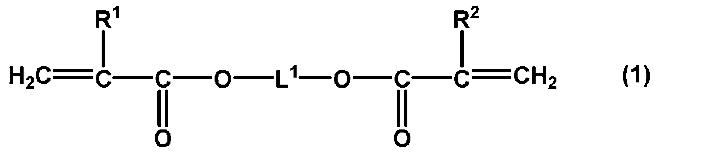
式(1)で表されるジ(メタ)アクリレート化合物としては、例えば、1,3-ブタンジオールジ(メタ)アクリレート、1,4-ブタンジオールジ(メタ)アクリレート、1,5-ペンタンジオールジ(メタ)アクリレート、1,6-ヘキサンジオールジ(メタ)アクリレート、1,7-ヘプタンジオールジ(メタ)アクリレート、1,8-オクタンジオールジ(メタ)アクリレート、3-メチル-1,5-ペンタンジオールジ(メタ)アクリレート、1,9-ノナンジオールジ(メタ)アクリレート、1,10-デカンジオールジ(メタ)アクリレート、ネオペンチルグリコールジ(メタ)アクリレート等のアルカンジオールジ(メタ)アクリレートが挙げられる。
モノマーとして、ジ(メタ)アクリレート化合物と共に、他の多官能モノマー及び/又は単官能モノマーを併用することができる。
多官能性モノマーとしては、例えば、ジビニルベンゼン、ジビニルビフェニル、ジビニルナフタレン等のジビニル化合物;(ポリ)エチレングリコールジ(メタ)アクリレート、(ポリ)プロピレングリコールジ(メタ)アクリレート、(ポリ)テトラメチレングリコールジ(メタ)アクリレート等の(ポリ)アルキレングリコール系ジ(メタ)アクリレート;トリメチロールプロパントリ(メタ)アクリレート、テトラメチロールメタントリ(メタ)アクリレート、テトラメチロールプロパンテトラ(メタ)アクリレート、ペンタエリスリトールトリ(メタ)アクリレート、1,1,1-トリスヒドロキシメチルエタントリ(メタ)アクリレート、1,1,1-トリスヒドロキシメチルプロパントリ(メタ)アクリレート等の3官能以上の(メタ)アクリレート;エトキシ化ビスフェノールA系ジ(メタ)アクリレート、プロポキシ化エトキシ化ビスフェノールA系ジ(メタ)アクリレート、トリシクロデカンジメタノールジ(メタ)アクリレート、1,1,1-トリスヒドロキシメチルエタンジ(メタ)アクリレート、エトキシ化シクロヘキサンジメタノールジ(メタ)アクリレート等のジ(メタ)アクリレート;ジアリルフタレート及びその異性体;トリアリルイソシアヌレート及びその誘導体などが挙げられる。これらモノマーの中でも、新中村化学工業株式会社製のNKエステル(A-TMPT-6P0、A-TMPT-3E0、A-TMM-3LMN、A-GLYシリーズ、A-9300、AD-TMP、AD-TMP-4CL、ATM-4E、A-DPH)等が、商業的に入手可能である。これらの多官能性モノマーは、単独で使用しても2種類以上を併用してもよい。
単官能性モノマーとしては、例えば、スチレン、o-メチルスチレン、m-メチルスチレン、p-メチルスチレン、α-メチルスチレン、o-エチルスチレン、m-エチルスチレン、p-エチルスチレン、2,4-ジメチルスチレン、p-n-ブチルスチレン、p-t-ブチルスチレン、p-n-ヘキシルスチレン、p-n-オクチルスチレン、p-n-ノニルスチレン、p-n-デシルスチレン、p-n-ドデシルスチレン、p-メトキシスチレン、p-フェニルスチレン、p-クロロスチレン、3,4-ジクロロスチレン等のスチレン及びその誘導体;アクリル酸メチル、アクリル酸エチル、アクリル酸プロピル、アクリル酸n-ブチル、アクリル酸イソブチル、アクリル酸ヘキシル、アクリル酸2-エチルヘキシル、アクリル酸n-オクチル、アクリル酸ドデシル、アクリル酸ラウリル、アクリル酸ステアリル、アクリル酸2-クロロエチル、アクリル酸フェニル、α-クロロアクリル酸メチル、メタクリル酸メチル、メタクリル酸エチル、メタクリル酸プロピル、メタクリル酸n-ブチル、メタクリル酸イソブチル、メタクリル酸ヘキシル、メタクリル酸2-エチルヘキシル、メタクリル酸n-オクチル、メタクリル酸ドデシル、メタクリル酸ラウリル、メタクリル酸ステアリル等の(メタ)アクリル酸エステル;酢酸ビニル、プロピオン酸ビニル、安息香酸ビニル、酪酸ビニル等のビニルエステル;N-ビニルピロール、N-ビニルカルバゾール、N-ビニルインドール、N-ビニルピロリドン等のN-ビニル化合物;フッ化ビニル、フッ化ビニリデン、テトラフルオロエチレン、ヘキサフルオロプロピレン、アクリル酸トリフルオロエチル、アクリル酸テトラフルオロプロピル等の含フッ素化モノマー;ブタジエン、イソプレン等の共役ジエンなどが挙げられる。これらは1種を単独で又は2種以上組み合わせて用いることができる。
水性媒体としては、水、又は、水と水溶性溶媒(例えば、低級アルコール)との混合媒体が挙げられる。水性媒体には、界面活性剤が含まれている。界面活性剤としては、アニオン系、カチオン系、ノニオン系及び両性イオン系の界面活性剤のうち、いずれも用いることができる。
アニオン系界面活性剤としては、例えば、オレイン酸ナトリウム、ヒマシ油カリ等の脂肪酸油、ラウリル硫酸ナトリウム、ラウリル硫酸アンモニウム等のアルキル硫酸エステル塩、ドデシルベンゼンスルホン酸ナトリウム等のアルキルベンゼンスルホン酸塩、アルキルナフタレンスルホン酸塩、アルカンスルホン酸塩、ジオクチルスルホコハク酸ナトリウム等のジアルキルスルホコハク酸塩、アルケルニルコハク酸塩(ジカリウム塩)、アルキルリン酸エステル塩、ナフタレンスルホン酸ホルマリン縮合物、ポリオキシエチレンアルキルフェニルエーテル硫酸エステル塩、ポリオキシエチレンラウリルエーテル硫酸ナトリウム等のポリオキシエチレンアルキルエーテル硫酸塩、ポリオキシエチレンアルキル硫酸エステル塩、ドデシル硫酸トリエタノールなどが挙げられる。
カチオン系界面活性剤としては、例えば、ラウリルアミンアセテート、ステアリルアミンアセテート等のアルキルアミン塩、ラウリルトリメチルアンモニウムクロライド等の第四級アンモニウム塩が挙げられる。
ノニオン系界面活性剤としては、例えば、ポリエチレングリコールアルキルエーテル類、ポリエチレングリコールアルキルアリールエーテル類、ポリエチレングリコールエステル類、ポリエチレングリコールソルビタンエステル類、ポリアルキレングリコールアルキルアミン又はアミド類等の炭化水素系ノニオン界面活性剤、シリコンのポリエチレンオキサイド付加物類、ポリプロピレンオキサイド付加物類等のポリエーテル変性シリコン系ノニオン界面活性剤、パーフルオロアルキルグリコール類等のフッ素系ノニオン界面活性剤などが挙げられる。
両性イオン系界面活性剤としては、例えば、ラウリルジメチルアミンオキサイド等の炭化水素界面活性剤、リン酸エステル系界面活性剤及び亜リン酸エステル系界面活性剤などが挙げられる。
界面活性剤は、1種を単独で又は2種以上を組み合わせて用いてもよい。上記界面活性剤の中でも、モノマーの重合時の分散安定性の観点から、アニオン系界面活性剤が好ましい。
必要に応じて添加される重合開始剤としては、例えば、過酸化ベンゾイル、過酸化ラウロイル、オルソクロロ過酸化ベンゾイル、オルソメトキシ過酸化ベンゾイル、3,5,5-トリメチルヘキサノイルパーオキサイド、t-ブチルパーオキシ-2-エチルヘキサノエート、ジ-t-ブチルパーオキサイド等の有機過酸化物;2,2’-アゾビスイソブチロニトリル、1,1’-アゾビスシクロヘキサンカルボニトリル、2,2’-アゾビス(2,4-ジメチルバレロニトリル)等のアゾ系化合物などが挙げられる。重合開始剤は、モノマー100質量部に対して、0.1~7.0質量部の範囲で使用するとよい。
次に、シード粒子に吸収させたモノマーを重合させることで、単分散性の樹脂粒子が得られる。
重合温度は、モノマー及び重合開始剤の種類に応じて、適宜選択することができる。重合温度は、25~110℃が好ましく、50~100℃がより好ましい。重合反応は、シード粒子が十分に膨潤し、モノマー及び任意に重合開始剤が完全に吸収された後に、昇温して行うのが好ましい。シード重合が終了した後は、必要に応じて重合液から遠心分離により水性媒体を除去し、水及び溶剤で洗浄した後、乾燥することで樹脂粒子が単離される。
上記重合工程において、シード粒子の分散安定性を向上させるために、乳化液に分散安定剤を添加してもよいが、本実施形態の樹脂粒子の製造方法では、重合中の樹脂粒子に働くせん断力が小さいため、分散安定剤を使用しなくてもよい。分散安定剤を使用しない場合、製造された樹脂粒子から分散安定剤を除去する工程を省略できるため、好ましい。
分散安定剤としては、例えば、ポリビニルアルコール、ポリカルボン酸、セルロース類(ヒドロキシエチルセルロース、カルボキシメチルセルロース等)及びポリビニルピロリドンが挙げられ、トリポリリン酸ナトリウム等の無機系水溶性高分子化合物も併用することができる。これらのうち、ポリビニルアルコール又はポリビニルピロリドンが好ましい。分散安定剤の添加量は、モノマー100質量部に対して1~10質量部が好ましい。
水中でモノマーが単独に乳化重合した粒子の発生を抑えるために、亜硝酸塩類、亜硫酸塩類、ハイドロキノン類、アスコルビン酸類、水溶性ビタミンB類、クエン酸、ポリフェノール類等の水溶性の重合禁止剤を用いてもよい。
<導電性粒子>
本実施形態の導電性粒子は、上記樹脂粒子と、該樹脂粒子の表面に形成された金属被膜とを有する。図4は、本実施形態に係る導電性粒子を示す模式断面図である。図4に示すように、導電性粒子40は、樹脂粒子41と、樹脂粒子41の表面を被覆している金属被膜(金属層)42とを有する。
本実施形態の導電性粒子は、上記樹脂粒子と、該樹脂粒子の表面に形成された金属被膜とを有する。図4は、本実施形態に係る導電性粒子を示す模式断面図である。図4に示すように、導電性粒子40は、樹脂粒子41と、樹脂粒子41の表面を被覆している金属被膜(金属層)42とを有する。
金属層42を構成する金属としては、特に限定されないが、例えば、金、銀、銅、白金、亜鉛、鉄、鉛、錫、アルミニウム、コバルト、インジウム、ニッケル、クロム、チタン、アンチモン、ビスマス、ゲルマニウム、カドミウム、錫-鉛合金、錫-銅合金、錫-銀合金及び錫-鉛-銀合金が挙げられる。中でも、金属層2は、ニッケル、銅、金又は錫-銀合金を含むことが好ましい。
樹脂粒子41の表面に金属層42を形成する方法は特に限定されない。金属層42を形成する方法として、例えば、無電解めっき法、電気めっき法、物理的蒸着法、金属粉末を含むペーストを樹脂粒子41の表面に塗布する方法が挙げられる。物理的蒸着法としては、真空蒸着、イオンプレーティング又はイオンスパッタリングを用いることができる。金属層42を形成する方法としては、無電解めっき法が好ましい。
金属層42は、単層であっても、2層以上が積層された複数の金属層であってもよい。電極間の接続抵抗を低減する観点から、導電性粒子40の表面(金属層42の最外層)は、金層、パラジウム層又は錫-銀合金層であることが好ましい。
金属層42の厚みは、0.02~1μmであることが好ましく、0.02~0.5μmであることがより好ましい。金属層42の厚みが0.02μm以上であれば、良好な導電性が発現し易くなり、1μm以下であれば、接続の際に導電性粒子が変形し易くなる。金属層2の厚みは、例えば、透過型電子顕微鏡(TEM)を用いて、導電性粒子の断面を観察することにより求めることができる。
導電性粒子40の平均粒径は、1.02~101μmが好ましく、1.5~80μmがより好ましく、2~67μmがさらに好ましい。
導電性粒子40の粒径のCV値は、10%以下であることが好ましく、7%以下であることがより好ましく、5%以下であることがさらに好ましい。導電性粒子40のCV値が10%以下であることにより、電気的な接続信頼性をより高くすることができる。
導電性粒子40の平均粒径及び粒径のCV値は、樹脂粒子41と同様の方法で測定することが可能である。
<異方導電材料>
本実施形態の異方導電材料は、上記導電性粒子と、バインダー樹脂とを含む。図5は、本実施形態に係る異方導電材料を示す模式断面図である。異方導電材料60は、絶縁性のバインダー樹脂50と、バインダー樹脂50中に分散された導電性粒子40とを備える。
本実施形態の異方導電材料は、上記導電性粒子と、バインダー樹脂とを含む。図5は、本実施形態に係る異方導電材料を示す模式断面図である。異方導電材料60は、絶縁性のバインダー樹脂50と、バインダー樹脂50中に分散された導電性粒子40とを備える。
バインダー樹脂50としては、熱硬化性樹脂、硬化剤、フィルム形成性ポリマー等を含有する熱硬化性樹脂組成物を用いることができる。
熱硬化性樹脂としては、特に限定されないが、耐熱性の観点からエポキシ樹脂を用いることが好ましい。エポキシ樹脂としては、分子内に2個以上のグリシジル基を有する各種のエポキシ化合物を用いることができ、例えば、ビスフェノール型エポキシ樹脂、ノボラック型エポキシ樹脂、ナフタレン型エポキシ樹脂、ビフェニル型エポキシ樹脂、脂環式型エポキシ樹脂、グリシジルアミン化合物、グリシジルエーテル化合物及びグリシジルエステル化合物が挙げられる。
エポキシ樹脂として、不純物イオン(Na+、Cl-等)、加水分解性塩素等を300ppm以下に低減した高純度品を用いると、エレクトロマイグレーションを防止し易くなる。
硬化剤としては特に限定されないが、潜在性硬化剤を用いることができる。潜在性硬化剤としては、例えば、イミダゾール化合物、ヒドラジド化合物、三フッ化ホウ素-アミン錯体、スルホニウム塩、アミンイミド、ポリアミンの塩及びジシアンジアミドが挙げられる。
フィルム形成性ポリマーは、異方導電材料をフィルム状に形成することができるものであれば特に限定されない。フィルム形成性ポリマーとしては、例えば、フェノキシ樹脂、ポリエステル樹脂、ポリアミド樹脂等の熱可塑性樹脂が挙げられる。
バインダー樹脂50には、接着後の応力を低減するため又は接着性を向上するために、ブタジエンゴム、アクリルゴム、スチレン-ブタジエンゴム、シリコーンゴム等を混合することができる。
バインダー樹脂50には、無機フィラーを配合することもできる。無機フィラーとして、例えば、シリカ、マグネシア、ベントナイト、スメクタイト、アルミナ又は窒化ホウ素からなるフィラーを用いることができる。
なお、バインダー樹脂50は、熱硬化性樹脂及び硬化剤に代えて、ラジカル重合性樹脂及び有機過酸化物等の光重合開始剤を含有する光硬化性樹脂組成物であってもよい。
異方導電材料60は、例えば、以下のようにして作製することができる。まず、エポキシ樹脂、アクリルゴム、潜在性硬化剤及びフィルム形成性ポリマーを含有する熱硬化性樹脂組成物を、必要に応じて有機溶剤に溶解又は分散させて液状化してバインダー樹脂50を調製する。次いで、バインダー樹脂50中に導電性粒子40を分散させることで液状の異方導電材料60が作製される。有機溶剤としては、樹脂成分を溶解することができ、常圧での沸点が50~150℃であるものが好ましい。
液状の異方導電材料60は、そのまま回路部材の接続に用いることができるが、フィルム状に成形して用いることができる。フィルム状の異方導電材料60は、液状の異方導電材料60を離型性フィルム上に塗布し、硬化剤の活性温度以下で有機溶剤を除去した後、離型性フィルムから剥離することにより作製することができる。離型性フィルムとしては、フッ素樹脂フィルム、ポリエチレンテレフタレートフィルム、ポリオレフィンフィルム等の樹脂フィルムが好適に用いられる。異方導電材料60は、フィルムの形状で使用すると、取り扱い性の点から便利である。
フィルム状の異方導電材料60の厚みは、導電性粒子40の平均粒径及び異方導電材料60の特性を考慮して相対的に決定されるが、1~100μmであることが好ましく、3~50μmであることがより好ましい。異方導電材料60の厚みが1μm以上であると十分な接着性が得られる傾向にあり、100μm以下であると導電性を得るために少量の導電性粒子40で十分な接続信頼性が得られる傾向にある。
<接続構造体>
本実施形態に係る回路部材の接続構造体48は、第一の回路基板44の主面上に第一の回路電極45が形成された第一の回路部材と、第二の回路基板46の主面上に第二の回路電極47が形成された第二の回路部材と、第一の回路部材と第二の回路部材との間に介在する接続部と、を備える。第二の回路部材は、第二の回路電極が第一の回路電極と対向するように配置されており、接続部は、上記本実施形態に係る導電性粒子を含む。
本実施形態に係る回路部材の接続構造体48は、第一の回路基板44の主面上に第一の回路電極45が形成された第一の回路部材と、第二の回路基板46の主面上に第二の回路電極47が形成された第二の回路部材と、第一の回路部材と第二の回路部材との間に介在する接続部と、を備える。第二の回路部材は、第二の回路電極が第一の回路電極と対向するように配置されており、接続部は、上記本実施形態に係る導電性粒子を含む。
図6は、本実施形態に係る異方導電材料を用いた回路部材の接続構造体の作製方法を示す模式断面図である。
まず、図6の(a)に示すように、第一の回路電極45が形成された第一の回路基板44と、第二の回路電極47が形成された第二の回路基板46とを準備し、異方導電材料60をその間に配置する。このとき、第一の回路電極45と第二の回路電極47とが対向するように位置を調整する。その後、第一の回路基板44と第二の回路基板46とを、第一の回路電極45と第二の回路電極47とが対向する方向で加圧加熱しつつ積層して、図6の(b)に示す接続構造体10を得る。接続構造体10は、異方導電材料60の硬化物により電気的に接続されている。
第一の回路基板44及び第二の回路基板46としては、ガラス基板、ポリイミド等のテープ基板、ドライバーIC等のベアチップ及びリジット型のパッケージ基板が挙げられる。
(第2実施形態)
図7は、本発明の第2実施形態に係る反応装置21の一例を示す模式断面図である。反応装置21は、反応液が収容される反応容器23と、反応容器23内に配置された撹拌体13と、撹拌体13を回転軸線Gの周りに回転させることにより、反応液を撹拌させる駆動部18と、を備える。撹拌体13としては、上述の反応装置1における撹拌体13と同様のものを用いることができるが、本実施形態では、撹拌体13は回転軸線G方向における反応容器23の底部側に設けられている。反応装置21は、導入部5及び蓋4を有していてもよい。導入部5、蓋4、及び駆動部18としては、上述の反応装置1と同様のものを用いることができる。
図7は、本発明の第2実施形態に係る反応装置21の一例を示す模式断面図である。反応装置21は、反応液が収容される反応容器23と、反応容器23内に配置された撹拌体13と、撹拌体13を回転軸線Gの周りに回転させることにより、反応液を撹拌させる駆動部18と、を備える。撹拌体13としては、上述の反応装置1における撹拌体13と同様のものを用いることができるが、本実施形態では、撹拌体13は回転軸線G方向における反応容器23の底部側に設けられている。反応装置21は、導入部5及び蓋4を有していてもよい。導入部5、蓋4、及び駆動部18としては、上述の反応装置1と同様のものを用いることができる。
反応容器23は、反応容器23内で撹拌される反応液の流れを反応容器23の下方かつ回転軸線Gに近づく方向に誘導する第一壁面3aを有する。ここで、従来の反応装置で用いられる反応容器は、回転軸線Gに対して平行な側面と平底から構成されているため、反応容器の壁面が反応液を反応容器の下方かつ回転軸線Gに近づく方向に誘導することができず、結果として反応容器内に反応液の流れが弱い領域が形成されてしまい、反応容器の撹拌体よりも下側全体を円滑に撹拌することができない。一方、本実施形態の反応容器23は、上述の第一壁面を有するため、撹拌体13を回転させた際に、吐出口15から吐出される反応液は、第一壁面3aに沿って撹拌体13の真下の方向へ誘導される。撹拌体13の真下の方向へ誘導される反応液の流れが撹拌体13の底部側に設けられた吸入口16に吸い上げられることにより、反応容器23内に反応液の淀みを生じることなく、円滑に循環流を生じることができる。このように、本実施形態の反応装置21は、従来の反応装置よりも円滑に反応液の撹拌を行うことができるため、樹脂粒子を製造する際に、樹脂粒子の粒径のCV値を小さくすることができる。さらに、従来の反応装置では、上述のとおり、流れの弱い領域が形成されてしまうため、合成途中の樹脂粒子等の固形物が重力により沈殿し、反応容器の底に堆積してしまう。特に、従来の反応装置でシード重合を行った場合、シード粒子が反応容器の底に堆積して凝集してしまうため、収率の低下及び得られる樹脂粒子のCV値の増加を招く。一方、本実施形態の反応装置21では、反応液中に分散した固形物が、反応容器23の下方かつ回転軸線Gに近づく方向に誘導される流れに乗り、撹拌体13の真下の方向に誘導されて撹拌体13の吸入口16から吸い上げられるため、固形物が沈殿することにより、反応容器23の底に堆積することを抑制できる。そのため、本実施形態の反応装置21は、樹脂粒子の製造に好適に用いることができ、特にシード重合に適している。
上記第一壁面3aは、回転軸線Gに対して垂直な断面における反応容器23の壁面に囲まれた領域の面積を減少させながら反応容器23の最下位置に至ると好ましく、縮径されながら反応容器23の最下位置に至るとより好ましい。ここで、縮径とは、垂直な断面における反応容器23の壁面に囲まれた領域の形状が略円形であり、当該円の直径が回転軸線Gに沿って反応容器23の最下位置の方向に向かうにつれて小さくなることをいう。反応容器23の具体的な形状としては、例えば、丸底及びナス型が挙げられる。
さらに、反応容器23は、第一壁面3aよりも上方に位置する第二壁面3bを有していてもよい。当該第二壁面3bは、反応容器23内で撹拌される反応液の流れを反応容器23の下方かつ回転軸線Gから離れる方向に誘導する。第二壁面を有することにより、より円滑に反応液の流れを反応容器23の下方かつ回転軸線Gに近づく方向に誘導することができる。
本実施形態の反応装置21を用いて、上述の第1実施形態と同様に樹脂粒子を製造することができる。また、第1実施形態と同様に、当該樹脂粒子を用いて、導電性粒子、異方導電材料及び接続構造体を製造することができる。
以下、実施例及び比較例を挙げて、本発明をより具体的に説明する。ただし、本発明は以下の実施例に限定されるものではない。
<シード粒子の合成>
(合成例1)
500mLの三口フラスコに、メタクリル酸メチル(MMA)70g、オクタンチオール(OCT)2.1g、ペルオキソ二硫酸カリウム(KPS)0.7g及び水400gを一括して仕込み、70℃のウォーターバスで加熱しながら、撹拌機を用いて約8時間撹拌をして、シード粒子(粒子径:700nm)を形成させた。
(合成例1)
500mLの三口フラスコに、メタクリル酸メチル(MMA)70g、オクタンチオール(OCT)2.1g、ペルオキソ二硫酸カリウム(KPS)0.7g及び水400gを一括して仕込み、70℃のウォーターバスで加熱しながら、撹拌機を用いて約8時間撹拌をして、シード粒子(粒子径:700nm)を形成させた。
<シード重合を用いた樹脂粒子の合成>
(乳化液の調製)
過酸化ベンゾイル1.33gを1,4-ブタンジオールジアクリレート(BDDA)18gに溶解したモノマーを、ドデシル硫酸トリエタノール3.0gが溶解したイオン交換水295gと混合し、超音波ホモジナイザーで10分間処理して乳化液を調製した。
(乳化液の調製)
過酸化ベンゾイル1.33gを1,4-ブタンジオールジアクリレート(BDDA)18gに溶解したモノマーを、ドデシル硫酸トリエタノール3.0gが溶解したイオン交換水295gと混合し、超音波ホモジナイザーで10分間処理して乳化液を調製した。
(実施例A1~10)
図1に示す反応容器を用いて、上記乳化液に、合成例1のシード粒子の分散液5.0g(シード粒子0.9g)を、導入口が回転軸線から見て撹拌体よりも反応容器の壁面側を向いている漏斗により加えて室温で12時間撹拌した後、連通路の内径が200μmの撹拌体を用いて80℃で8時間重合を行い、樹脂粒子を合成した。撹拌体の形状及び連通路の数の関係と、各実施例での樹脂粒子の合成結果を表1に示す。いずれも十分に単分散だが、実施例A9の形態で得られる樹脂粒子が最も単分散であることが分かった。なお、表1において、上及び下は回転軸線に平行な上方向及び下方向を指し、横は回転軸線に直行する方向を指す。
図1に示す反応容器を用いて、上記乳化液に、合成例1のシード粒子の分散液5.0g(シード粒子0.9g)を、導入口が回転軸線から見て撹拌体よりも反応容器の壁面側を向いている漏斗により加えて室温で12時間撹拌した後、連通路の内径が200μmの撹拌体を用いて80℃で8時間重合を行い、樹脂粒子を合成した。撹拌体の形状及び連通路の数の関係と、各実施例での樹脂粒子の合成結果を表1に示す。いずれも十分に単分散だが、実施例A9の形態で得られる樹脂粒子が最も単分散であることが分かった。なお、表1において、上及び下は回転軸線に平行な上方向及び下方向を指し、横は回転軸線に直行する方向を指す。
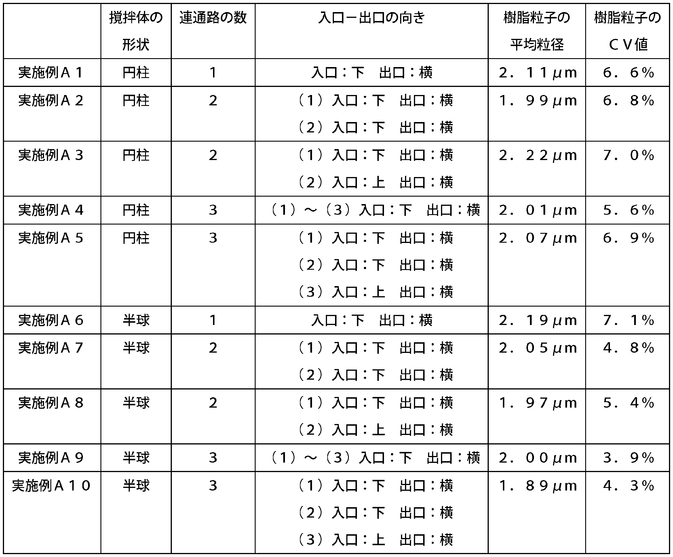
(実施例A11)
過酸化ベンゾイル1.33gを1,4-ブタンジオールジアクリレート(BDDA)18gに溶解したモノマーを、ドデシル硫酸トリエタノール3.0gが溶解したイオン交換水295gと混合し、超音波ホモジナイザーで10分間処理して乳化液を調製した。
過酸化ベンゾイル1.33gを1,4-ブタンジオールジアクリレート(BDDA)18gに溶解したモノマーを、ドデシル硫酸トリエタノール3.0gが溶解したイオン交換水295gと混合し、超音波ホモジナイザーで10分間処理して乳化液を調製した。
この乳化液に、合成例1のシード粒子の分散液5.0gを加えて室温で12時間撹拌した後、連通路の内径が200μmの撹拌体を用いて80℃で8時間重合を行ったこと以外は、実施例A9と同様にして樹脂粒子を合成した。
(実施例A12)
合成例1のシード粒子分散液の添加量を0.6g(シード粒子0.1g)に変更し、連通路の内径が400μmの撹拌体を用いた以外は、実施例A9と同様にして樹脂粒子を合成した。
合成例1のシード粒子分散液の添加量を0.6g(シード粒子0.1g)に変更し、連通路の内径が400μmの撹拌体を用いた以外は、実施例A9と同様にして樹脂粒子を合成した。
(実施例A13)
合成例1のシード粒子分散液の添加量を0.2g(シード粒子0.03g)に変更し、連通路の内径が600μmの撹拌体を用いた以外は、実施例A9と同様にして樹脂粒子を合成した。
合成例1のシード粒子分散液の添加量を0.2g(シード粒子0.03g)に変更し、連通路の内径が600μmの撹拌体を用いた以外は、実施例A9と同様にして樹脂粒子を合成した。
(実施例A14)
合成例1のシード粒子分散液の添加量を0.07g(シード粒子0.01g)に変更し、連通路の内径が800μmの撹拌体を用いた以外は、実施例A9と同様にして樹脂粒子を合成した。
合成例1のシード粒子分散液の添加量を0.07g(シード粒子0.01g)に変更し、連通路の内径が800μmの撹拌体を用いた以外は、実施例A9と同様にして樹脂粒子を合成した。
(実施例A15)
合成例1のシード粒子分散液の添加量を0.04g(シード粒子0.007g)へと変更し、連通路の内径が1000μm(1mm)の撹拌体を用いた以外は、実施例A9と同様にして樹脂粒子を合成した。
合成例1のシード粒子分散液の添加量を0.04g(シード粒子0.007g)へと変更し、連通路の内径が1000μm(1mm)の撹拌体を用いた以外は、実施例A9と同様にして樹脂粒子を合成した。
(比較例A1)
上記撹拌体に代えて、6枚の羽根を有したディスクタービンを用い、容器内にバッフルを装着した以外は実施例A11と同様にして樹脂粒子を合成した。
上記撹拌体に代えて、6枚の羽根を有したディスクタービンを用い、容器内にバッフルを装着した以外は実施例A11と同様にして樹脂粒子を合成した。
各実施例及び比較例で得られた樹脂粒子の粒子径を湿式フロー式粒子径・形状分析装置(シスメックス株式会社製)で測定し、平均粒子径及び粒子径のCV値を算出した。結果を表1及び2に示す。
表1の結果より、本発明の製造方法で合成した粒子は非常に単分散であることを確認した。
[導電性粒子の作製]
実施例A11~15及び比較例A1で得られた樹脂粒子表面に、それぞれ厚み0.2μmのニッケル層を無電解めっき法で形成し、さらにそのニッケル層の外側に厚み0.04μmのパラジウム層を形成して、導電性粒子A11~16をそれぞれ作製した。
実施例A11~15及び比較例A1で得られた樹脂粒子表面に、それぞれ厚み0.2μmのニッケル層を無電解めっき法で形成し、さらにそのニッケル層の外側に厚み0.04μmのパラジウム層を形成して、導電性粒子A11~16をそれぞれ作製した。
[異方導電材料の作製]
導電性粒子A11~16を用いて、以下のとおり、異方導電材料の作製を行った。
導電性粒子A11~16を用いて、以下のとおり、異方導電材料の作製を行った。
フェノキシ樹脂(ユニオンカーバイド社製、商品名「PKHC」)5質量部、アクリルゴム(ブチルアクリレート、エチルアクリレート、アクリロニトリル及びグリシジルメタクリレートの共重合体、共重合比(質量)40/30/30/3、Mw850,000)18質量部、エポキシ樹脂(三菱化学株式会社製、商品名「YL-983U」)15質量部を酢酸エチル10質量部に溶解した溶液に、カチオン系硬化剤(三新化学工業株式会社製、商品名「SI-60」)を2質量部添加し、熱硬化性樹脂組成物を調製した。次いで、上記熱硬化性樹脂組成物に、シリカフィラー(日本アエロジル株式会社製、商品名「Aerosil R805」)10質量部の酢酸エチル分散液30質量部を加え混合した後、導電性粒子20質量部及び酢酸エチル10質量部を加えて超音波分散を行い、液状の異方導電材料を作製した。
液状の異方導電材料を、シリコーン処理したポリエチレンテレフタレートフィルム(厚み40μm、以下、「PETフィルム」と表記する)上にロールコータで塗布し、80℃で5分間乾燥して厚み20μmのフィルム状の異方導電材料を作製した。
[接続構造体の作製]
作製したフィルム状の異方導電材料を用いて、金バンプ(面積:30μm×90μm、スペース10μm、高さ:15μm、バンプ数:362)付きチップ(1.7mm×17mm、厚み:0.5mm)と、AlNd膜付きガラス基板(ジオマテック製、厚み:0.7mm)との熱圧着を、以下のとおり行い、接続構造体を作製した。
作製したフィルム状の異方導電材料を用いて、金バンプ(面積:30μm×90μm、スペース10μm、高さ:15μm、バンプ数:362)付きチップ(1.7mm×17mm、厚み:0.5mm)と、AlNd膜付きガラス基板(ジオマテック製、厚み:0.7mm)との熱圧着を、以下のとおり行い、接続構造体を作製した。
所定のサイズ(2mm×19mm)に切断したフィルム状異方導電材料のPETフィルムが設けられた面とは反対側の面を、AlNd膜付きガラス基板のAlNd膜が形成された面上に、80℃、0.98MPa(10kgf/cm2)、5秒間の条件で貼り付けた。その後、PETフィルムを剥離し、異方導電材料を介して、170℃、70MPa、5秒間の条件で加熱及び加圧を行って実装サンプル(接続構造体)を得た。
(圧痕の確認)
液晶パネル検査用顕微鏡(BH3-MJL、オリンパス株式会社製)を用いて、ノマルスキー微分干渉観察によりガラス基板側から圧痕の状態を観察した。はっきり輪郭を確認できる場合を良好、それ以外を不明瞭とした。また、圧痕を1000個カウントし、不明瞭な圧痕の数が50個以上をB、50個未満をAとして圧痕のバラツキを評価した。結果を表2に示す。
液晶パネル検査用顕微鏡(BH3-MJL、オリンパス株式会社製)を用いて、ノマルスキー微分干渉観察によりガラス基板側から圧痕の状態を観察した。はっきり輪郭を確認できる場合を良好、それ以外を不明瞭とした。また、圧痕を1000個カウントし、不明瞭な圧痕の数が50個以上をB、50個未満をAとして圧痕のバラツキを評価した。結果を表2に示す。
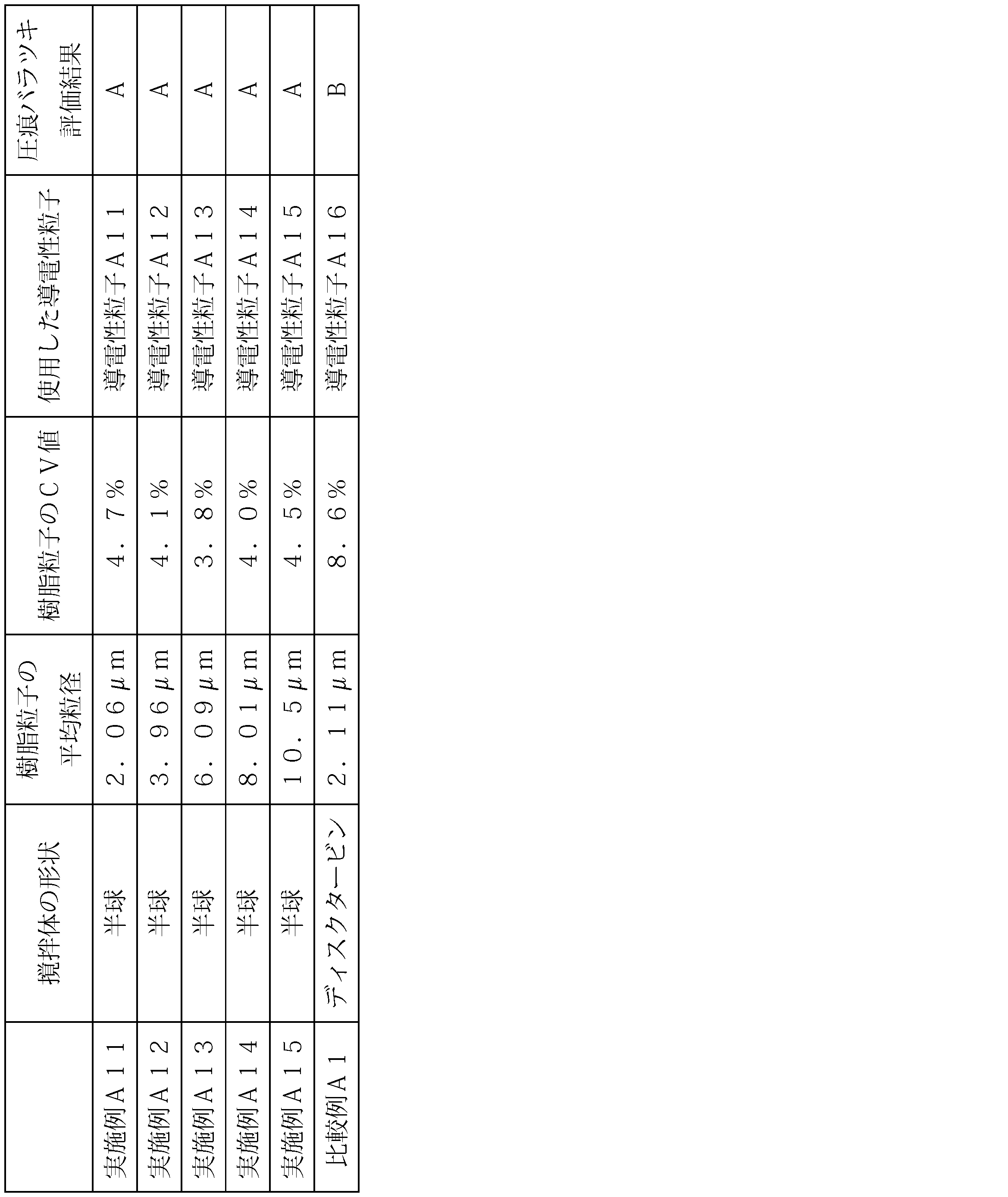
本実施形態の製造方法で合成された樹脂粒子は高い単分散性を有することが確認された。また、該樹脂粒子を用いて形成した導電性粒子を用いることで、圧痕バラツキの少ない接続構造体が作製できることが確認された。
<反応容器形状の検討>
(実施例B1)
過酸化ベンゾイル1.33gを1,4-ブタンジオールジアクリレート(BDDA)18gに溶解したモノマーを、ドデシル硫酸トリエタノール3.0gが溶解したイオン交換水295gと混合し、超音波ホモジナイザーで10分間処理して乳化液を調製した。
(実施例B1)
過酸化ベンゾイル1.33gを1,4-ブタンジオールジアクリレート(BDDA)18gに溶解したモノマーを、ドデシル硫酸トリエタノール3.0gが溶解したイオン交換水295gと混合し、超音波ホモジナイザーで10分間処理して乳化液を調製した。
合成する容器として丸底フラスコを用いて、上記乳化液に、合成例1のシード粒子の分散液5.0g(シード粒子0.9g)を加えて室温で12時間撹拌した後、連通路の内径が200μmの撹拌体を用いて80℃で8時間重合を行い、樹脂粒子を合成した。
(実施例B2)
合成例1のシード粒子分散液の添加量を0.6g(シード粒子0.1g)に変更し、連通路の内径が400μmの撹拌体を用いた以外は、実施例B1と同様にして樹脂粒子を合成した。
合成例1のシード粒子分散液の添加量を0.6g(シード粒子0.1g)に変更し、連通路の内径が400μmの撹拌体を用いた以外は、実施例B1と同様にして樹脂粒子を合成した。
(実施例B3)
連通路の内径が1.0mmの撹拌体を用いた以外は、実施例B2と同様にして樹脂粒子を合成した。
連通路の内径が1.0mmの撹拌体を用いた以外は、実施例B2と同様にして樹脂粒子を合成した。
(実施例B4)
連通路の内径が5.0mmの撹拌体を用いた以外は、実施例B2と同様にして樹脂粒子を合成した。
連通路の内径が5.0mmの撹拌体を用いた以外は、実施例B2と同様にして樹脂粒子を合成した。
(実施例B5)
連通路の内径が10.0mmの撹拌体を用いた以外は、実施例B2と同様にして樹脂粒子を合成した。
連通路の内径が10.0mmの撹拌体を用いた以外は、実施例B2と同様にして樹脂粒子を合成した。
(実施例B6)
合成例1のシード粒子分散液の添加量を0.2g(シード粒子0.03g)に変更し、連通路の内径が10.0mmの撹拌体を用いた以外は、実施例B1と同様にして樹脂粒子を合成した。
合成例1のシード粒子分散液の添加量を0.2g(シード粒子0.03g)に変更し、連通路の内径が10.0mmの撹拌体を用いた以外は、実施例B1と同様にして樹脂粒子を合成した。
(実施例B7)
合成例1のシード粒子分散液の添加量を0.07g(シード粒子0.01g)に変更し、連通路の内径が10.0mmの撹拌体を用いた以外は、実施例B1と同様にして樹脂粒子を合成した。
合成例1のシード粒子分散液の添加量を0.07g(シード粒子0.01g)に変更し、連通路の内径が10.0mmの撹拌体を用いた以外は、実施例B1と同様にして樹脂粒子を合成した。
(実施例B8)
合成例1のシード粒子分散液の添加量を0.04g(シード粒子0.007g)へと変更し、連通路の内径が10.0mmの撹拌体を用いた以外は、実施例B1と同様にして樹脂粒子を合成した。
合成例1のシード粒子分散液の添加量を0.04g(シード粒子0.007g)へと変更し、連通路の内径が10.0mmの撹拌体を用いた以外は、実施例B1と同様にして樹脂粒子を合成した。
(実施例B9)
合成する容器をなす型フラスコに代え、連通路の内径が10.0mmの撹拌体を用いた以外は実施例B1と同様にして樹脂粒子を合成した。
合成する容器をなす型フラスコに代え、連通路の内径が10.0mmの撹拌体を用いた以外は実施例B1と同様にして樹脂粒子を合成した。
(比較例B1)
合成する容器を回転軸線に平行な側面と回転軸線に垂直な底面を有するシリンダー型のようを用いた以外は実施例B1と同様にして樹脂粒子を合成した。
合成する容器を回転軸線に平行な側面と回転軸線に垂直な底面を有するシリンダー型のようを用いた以外は実施例B1と同様にして樹脂粒子を合成した。
(比較例B2)
前記撹拌体に代えて、撹拌体を6枚の羽根を有した垂直ディスクタービンを用いた以外は実施例B1と同様にして樹脂粒子を合成した。
前記撹拌体に代えて、撹拌体を6枚の羽根を有した垂直ディスクタービンを用いた以外は実施例B1と同様にして樹脂粒子を合成した。
(比較例B3)
前記撹拌体に代えて、撹拌体を4枚の羽根を有したパドルタービン(羽根角度45°)を用いた以外は実施例B1と同様にして樹脂粒子を合成した。
前記撹拌体に代えて、撹拌体を4枚の羽根を有したパドルタービン(羽根角度45°)を用いた以外は実施例B1と同様にして樹脂粒子を合成した。
各実施例及び比較例で得られた樹脂粒子の粒径を湿式フロー式粒子径・形状分析装置(シスメックス株式会社製)で測定し、平均粒径及び粒径のCV値を算出した。結果を表3に示す。
表3の結果より、本発明の製造方法で合成した粒子は非常に単分散であることを確認した。
導電性粒子の作製
実施例B1~9及び比較例B1~3で得られた樹脂粒子表面に、それぞれ厚み0.2μmのニッケル層を無電解めっき法で形成し、さらにそのニッケル層の外側に厚み0.04μmのパラジウム層を形成して、導電性粒子B1~12をそれぞれ作製した。
実施例B1~9及び比較例B1~3で得られた樹脂粒子表面に、それぞれ厚み0.2μmのニッケル層を無電解めっき法で形成し、さらにそのニッケル層の外側に厚み0.04μmのパラジウム層を形成して、導電性粒子B1~12をそれぞれ作製した。
[異方導電材料の作製]
導電性粒子B1~12を用いて、以下のとおり、異方導電材料の作製を行った。
導電性粒子B1~12を用いて、以下のとおり、異方導電材料の作製を行った。
フェノキシ樹脂(ユニオンカーバイド社製、商品名「PKHC」)5質量部、アクリルゴム(ブチルアクリレート、エチルアクリレート、アクリロニトリル及びグリシジルメタクリレートの共重合体、共重合比(質量)40/30/30/3、Mw850,000)18質量部、エポキシ樹脂(三菱化学株式会社製、商品名「YL-983U」)15質量部を酢酸エチル10質量部に溶解した溶液に、カチオン系硬化剤(三新化学工業株式会社製、商品名「SI-60」)を2質量部添加し、熱硬化性樹脂組成物を調製した。次いで、上記熱硬化性樹脂組成物に、シリカフィラー(日本アエロジル株式会社製、商品名「Aerosil R805」)10質量部の酢酸エチル分散液30質量部を加え混合した後、導電性粒子20質量部及び酢酸エチル10質量部を加えて超音波分散を行い、液状の異方導電材料を作製した。
液状の異方導電材料を、シリコーン処理したポリエチレンテレフタレートフィルム(厚み40μm、以下、「PETフィルム」と表記する)上にロールコータで塗布し、80℃で5分間乾燥して厚み20μmのフィルム状の異方導電材料を作製した。
[接続構造体の作製]
作製したフィルム状の異方導電材料を用いて、金バンプ(面積:30μm×90μm、スペース10μm、高さ:15μm、バンプ数:362)付きチップ(1.7mm×17mm、厚み:0.5mm)と、AlNd膜付きガラス基板(ジオマテック製、厚み:0.7mm)との熱圧着を、以下のとおり行い、接続構造体を作製した。
作製したフィルム状の異方導電材料を用いて、金バンプ(面積:30μm×90μm、スペース10μm、高さ:15μm、バンプ数:362)付きチップ(1.7mm×17mm、厚み:0.5mm)と、AlNd膜付きガラス基板(ジオマテック製、厚み:0.7mm)との熱圧着を、以下のとおり行い、接続構造体を作製した。
所定のサイズ(2mm×19mm)に切断したフィルム状異方導電材料のPETフィルムが設けられた面とは反対側の面を、AlNd膜付きガラス基板のAlNd膜が形成された面上に、80℃、0.98MPa(10kgf/cm2)、5秒間の条件で貼り付けた。その後、PETフィルムを剥離し、異方導電材料を介して、170℃、70MPa、5秒間の条件で加熱及び加圧を行って実装サンプル(接続構造体)を得た。
(圧痕の確認)
液晶パネル検査用顕微鏡(BH3-MJL、オリンパス株式会社製)を用いて、ノマルスキー微分干渉観察によりガラス基板側から圧痕の状態を観察した。はっきり輪郭を確認できる場合を良好、それ以外を不明瞭とした。また、圧痕を1000個カウントし、不明瞭な圧痕の数が50個以上をB、50個未満をAとして圧痕のバラツキを評価した。結果を表3に併せて示す。
液晶パネル検査用顕微鏡(BH3-MJL、オリンパス株式会社製)を用いて、ノマルスキー微分干渉観察によりガラス基板側から圧痕の状態を観察した。はっきり輪郭を確認できる場合を良好、それ以外を不明瞭とした。また、圧痕を1000個カウントし、不明瞭な圧痕の数が50個以上をB、50個未満をAとして圧痕のバラツキを評価した。結果を表3に併せて示す。
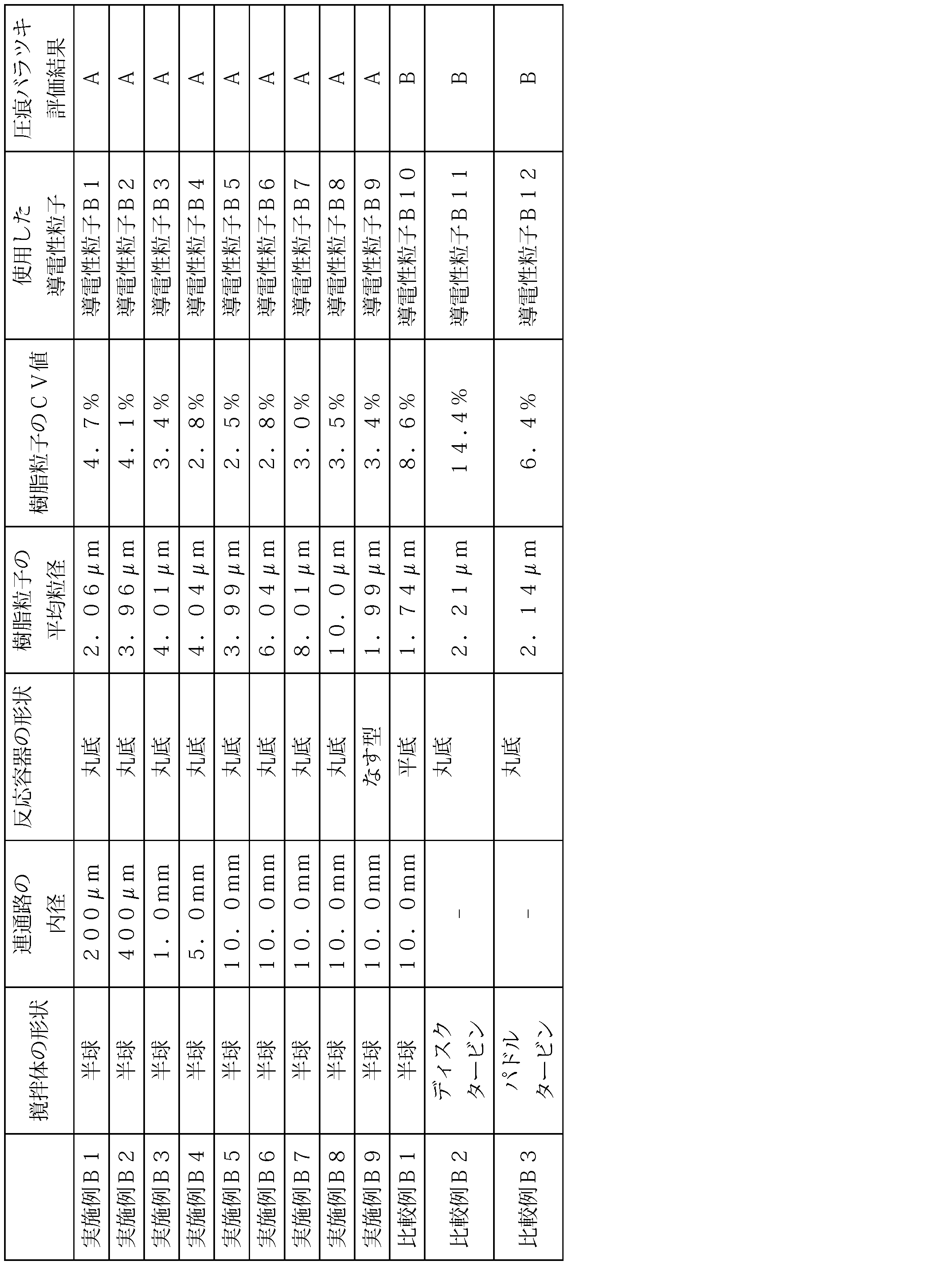
本実施形態の製造方法で合成された樹脂粒子は高い単分散性を有することが確認された。また、該樹脂粒子を用いて形成した導電性粒子を用いることで、圧痕バラツキの少ない接続構造体が作製できることが確認された。
1、21…反応装置、3、23…反応容器、3a…第一壁面、3b…第二壁面、4…蓋、5…導入部、11、31…軸体、12…基体、13、33…撹拌体、14、34…連通路、15、35…吐出口、16、36…吸入口、18…駆動部、40…導電性粒子、41…樹脂粒子、42…金属層、50…バインダー樹脂、60…異方導電材料、44…第一の回路基板、45…第一の回路電極、46…第二の回路基板、47…第二の回路電極、48…接続構造体、G…回転軸線。
Claims (14)
- 反応液が収容される反応容器と、
前記反応容器内に配置される撹拌体と、
前記撹拌体を回転軸線の周りに回転させることにより、反応液を撹拌させる駆動部と、を備え、
前記撹拌体は、前記回転軸線の周りに回転対称な凸形状の基体の表面に吐出口及び当該吐出口と前記基体内部に設けられた連通路を介して連通された吸入口を設けた形状を有しており、
前記吸入口は、前記吐出口よりも前記回転軸線に近い位置に設けられている、反応装置。 - 前記吸入口は、前記回転軸線方向における前記反応容器の底部側に設けられており、
前記反応容器は、前記反応容器内で撹拌される反応液の流れを前記反応容器の下方かつ前記回転軸線に近づく方向に誘導する第一壁面を有する、請求項1に記載の反応装置。 - 前記第一壁面は、前記回転軸線に対して垂直な断面における前記反応容器の壁面に囲まれた領域の面積を減少させながら前記反応容器の最下位置に至る、請求項2に記載の反応装置。
- 前記第一壁面は、縮径されながら前記反応容器の最下位置に至る、請求項2に記載の反応装置。
- 前記反応容器は、前記第一壁面よりも上方に位置する第二壁面を有し、
前記第二壁面は、前記反応容器内で撹拌される反応液の流れを前記反応容器の下方かつ前記回転軸線から離れる方向に誘導する、請求項2~4のいずれか1項に記載の反応装置。 - 前記反応容器が丸底である、請求項2~5のいずれか1項に記載の反応装置。
- 前記反応容器内に原料を導入可能な導入部をさらに備える、請求項1~6のいずれか一項に記載の反応装置。
- 前記導入部が、前記回転軸線から見て前記撹拌体よりも遠い位置に原料を導入するよう構成されている、請求項7に記載の反応装置。
- シード重合用である、請求項1~8のいずれか1項に記載の反応装置。
- 反応容器内でシード粒子及びモノマーを含む乳化液を撹拌しながら重合反応を行って樹脂粒子を製造する方法において、
反応容器内で回転軸線の周りに撹拌体を回転させることにより前記乳化液を撹拌し、
前記撹拌体は、前記回転軸線の周りに回転対称である基体の表面に吐出口及び当該吐出口と前記基体内部に設けられた連通路を介して連通された吸入口を設けた形状を有しており、
前記吸入口は、前記吐出口よりも前記回転軸線に近い位置に設けられている、方法。 - 前記吸入口は、前記回転軸線方向における前記反応容器の底部側に設けられており、
前記反応容器は、前記反応容器内で撹拌される反応液の流れを前記反応容器の下方かつ前記回転軸線に近づく方向に誘導する第一壁面を有する、請求項10に記載の方法。 - 請求項10又は11に記載の方法により製造された樹脂粒子の表面に金属被膜を形成する工程を備える、導電性粒子の製造方法。
- 請求項12に記載の方法により製造された導電性粒子とバインダー樹脂とを混合する工程を備える、異方導電材料の製造方法。
- 第一の回路電極を有する第一の回路部材と第二の回路電極を有する第二の回路部材との間に請求項13に記載の方法により製造された異方導電材料を配置し、前記第一の回路部材及び前記第二の回路部材を介して前記異方導電材料を加熱及び加圧して硬化させ、前記第一の回路部材と前記第二の回路部材とを接着すると共に前記第一の回路電極と前記第二の回路電極とを電気的に接続する工程を備える、接続構造体の製造方法。
Priority Applications (2)
| Application Number | Priority Date | Filing Date | Title |
|---|---|---|---|
| KR1020187030572A KR102302526B1 (ko) | 2016-03-23 | 2017-03-14 | 반응 장치, 그리고 수지 입자, 도전성 입자, 이방 도전 재료 및 접속 구조체의 제조 방법 |
| CN201780018806.5A CN108884178B (zh) | 2016-03-23 | 2017-03-14 | 反应装置、以及树脂粒子、导电性粒子、各向异性导电材料和连接结构体的制造方法 |
Applications Claiming Priority (4)
| Application Number | Priority Date | Filing Date | Title |
|---|---|---|---|
| JP2016059074A JP6775730B2 (ja) | 2016-03-23 | 2016-03-23 | 反応装置及び樹脂粒子の製造方法 |
| JP2016-059070 | 2016-03-23 | ||
| JP2016059070A JP6775729B2 (ja) | 2016-03-23 | 2016-03-23 | 反応装置、並びに樹脂粒子、導電性粒子、異方導電材料及び接続構造体の製造方法 |
| JP2016-059074 | 2016-03-23 |
Publications (1)
| Publication Number | Publication Date |
|---|---|
| WO2017164012A1 true WO2017164012A1 (ja) | 2017-09-28 |
Family
ID=59899482
Family Applications (1)
| Application Number | Title | Priority Date | Filing Date |
|---|---|---|---|
| PCT/JP2017/010238 Ceased WO2017164012A1 (ja) | 2016-03-23 | 2017-03-14 | 反応装置、並びに樹脂粒子、導電性粒子、異方導電材料及び接続構造体の製造方法 |
Country Status (4)
| Country | Link |
|---|---|
| KR (1) | KR102302526B1 (ja) |
| CN (1) | CN108884178B (ja) |
| TW (1) | TWI720160B (ja) |
| WO (1) | WO2017164012A1 (ja) |
Citations (5)
| Publication number | Priority date | Publication date | Assignee | Title |
|---|---|---|---|---|
| JP2011255289A (ja) * | 2010-06-08 | 2011-12-22 | Eddy Plus Co Ltd | 攪拌用回転体および攪拌装置 |
| JP2014123453A (ja) * | 2012-12-20 | 2014-07-03 | Hitachi Chemical Co Ltd | 導電性粒子、異方性導電材料及び回路部材の接続構造体 |
| JP2015047540A (ja) * | 2013-08-30 | 2015-03-16 | 株式会社石井鐵工所 | 遠心撹拌体 |
| JP2015136682A (ja) * | 2014-01-24 | 2015-07-30 | 株式会社田定工作所 | 撹拌用回転体及び撹拌装置 |
| JP2015171695A (ja) * | 2014-03-12 | 2015-10-01 | ヤマテック株式会社 | 攪拌装置 |
Family Cites Families (9)
| Publication number | Priority date | Publication date | Assignee | Title |
|---|---|---|---|---|
| US5846657A (en) | 1996-07-25 | 1998-12-08 | Rohm And Haas Company | Liquid crystal displays containing spacers and methods for producing the spacer |
| JP4779186B2 (ja) | 1999-04-23 | 2011-09-28 | 東ソー株式会社 | 粒径単分散粒子、その製造方法及びそれを用いた用途 |
| JP3739232B2 (ja) | 1999-05-06 | 2006-01-25 | 積水化学工業株式会社 | 重合体微粒子及びその製造方法、液晶表示素子用スペーサ、導電性微粒子 |
| JP4247147B2 (ja) * | 2004-03-26 | 2009-04-02 | 積水化成品工業株式会社 | 単分散樹脂粒子の製造方法 |
| JP2005327509A (ja) | 2004-05-12 | 2005-11-24 | Sekisui Chem Co Ltd | 導電性微粒子及び異方性導電材料 |
| JP5185839B2 (ja) | 2009-01-07 | 2013-04-17 | 積水化学工業株式会社 | 導電性粒子、異方性導電材料及び接続構造体 |
| WO2010150656A1 (ja) * | 2009-06-23 | 2010-12-29 | 株式会社エディプラス | 攪拌用回転体および攪拌装置 |
| US9925503B2 (en) * | 2012-12-25 | 2018-03-27 | M. Technique Co., Ltd. | Stirring-processing apparatus and processing method |
| CN104193853B (zh) * | 2014-08-20 | 2015-12-30 | 天津大学 | 制备单分散离子交换树脂的设备及方法 |
-
2017
- 2017-03-14 KR KR1020187030572A patent/KR102302526B1/ko active Active
- 2017-03-14 WO PCT/JP2017/010238 patent/WO2017164012A1/ja not_active Ceased
- 2017-03-14 CN CN201780018806.5A patent/CN108884178B/zh active Active
- 2017-03-22 TW TW106109430A patent/TWI720160B/zh active
Patent Citations (5)
| Publication number | Priority date | Publication date | Assignee | Title |
|---|---|---|---|---|
| JP2011255289A (ja) * | 2010-06-08 | 2011-12-22 | Eddy Plus Co Ltd | 攪拌用回転体および攪拌装置 |
| JP2014123453A (ja) * | 2012-12-20 | 2014-07-03 | Hitachi Chemical Co Ltd | 導電性粒子、異方性導電材料及び回路部材の接続構造体 |
| JP2015047540A (ja) * | 2013-08-30 | 2015-03-16 | 株式会社石井鐵工所 | 遠心撹拌体 |
| JP2015136682A (ja) * | 2014-01-24 | 2015-07-30 | 株式会社田定工作所 | 撹拌用回転体及び撹拌装置 |
| JP2015171695A (ja) * | 2014-03-12 | 2015-10-01 | ヤマテック株式会社 | 攪拌装置 |
Also Published As
| Publication number | Publication date |
|---|---|
| CN108884178A (zh) | 2018-11-23 |
| CN108884178B (zh) | 2021-06-04 |
| KR102302526B1 (ko) | 2021-09-14 |
| KR20180127439A (ko) | 2018-11-28 |
| TW201737266A (zh) | 2017-10-16 |
| TWI720160B (zh) | 2021-03-01 |
Similar Documents
| Publication | Publication Date | Title |
|---|---|---|
| JP4387175B2 (ja) | 被覆導電性粒子、異方性導電材料及び導電接続構造体 | |
| KR100893550B1 (ko) | 코팅된 미립자 및 그 제조 방법 및 전도성 미립자 | |
| WO2012102199A1 (ja) | 導電性微粒子、樹脂粒子及びそれを用いた異方性導電材料 | |
| JP5559555B2 (ja) | 重合体微粒子及びその用途 | |
| WO2015141716A1 (ja) | 樹脂粒子、導電性微粒子及びそれを用いた異方性導電材料 | |
| JP6775729B2 (ja) | 反応装置、並びに樹脂粒子、導電性粒子、異方導電材料及び接続構造体の製造方法 | |
| JP6044254B2 (ja) | 架橋ポリマー粒子、導電性粒子、異方性導電材料及び回路部材の接続構造体 | |
| JP2006269296A (ja) | 突起粒子の製造方法、突起粒子、導電性突起粒子及び異方性導電材料 | |
| JP2013105535A (ja) | 導電粒子、異方導電材料及び導電接続構造体 | |
| JP6775730B2 (ja) | 反応装置及び樹脂粒子の製造方法 | |
| KR102302526B1 (ko) | 반응 장치, 그리고 수지 입자, 도전성 입자, 이방 도전 재료 및 접속 구조체의 제조 방법 | |
| JP2011173965A (ja) | 重合体微粒子及びその製造方法、ならびに、その用途 | |
| JP6123283B2 (ja) | 導電性粒子、異方性導電材料及び回路部材の接続構造体 | |
| JP7255102B2 (ja) | 樹脂粒子の製造方法、導電性粒子の製造方法、異方導電材料の製造方法、及び接続構造体の製造方法 | |
| JP2016041803A (ja) | 基材粒子、導電性粒子、導電材料及び接続構造体 | |
| JP6182846B2 (ja) | 架橋ポリマー粒子、導電性粒子、異方性導電材料及び回路部材の接続構造体 | |
| JP6136182B2 (ja) | 架橋ポリマー粒子、導電性粒子、異方性導電材料及び回路部材の接続構造体 | |
| JP6498505B2 (ja) | 導電性微粒子及びそれを用いた異方性導電材料 | |
| JP2013105537A (ja) | 撥水性導電粒子、異方導電材料及び導電接続構造体 | |
| JP7715145B2 (ja) | 導電性複合粒子の製造方法、導電性複合粒子、及び回路接続用接着剤フィルム | |
| JP7522573B2 (ja) | 粒子及び分級方法 | |
| JP5581276B2 (ja) | 導電性微粒子 | |
| JP7844945B2 (ja) | 導電粒子、回路接続用接着フィルム及びその製造方法、並びに、接続構造体及びその製造方法 | |
| WO2023171630A1 (ja) | 導電粒子、回路接続用接着フィルム及びその製造方法、並びに、接続構造体及びその製造方法 | |
| WO2023171634A1 (ja) | 導電粒子、回路接続用接着フィルム及びその製造方法、並びに、接続構造体及びその製造方法 |
Legal Events
| Date | Code | Title | Description |
|---|---|---|---|
| NENP | Non-entry into the national phase |
Ref country code: DE |
|
| ENP | Entry into the national phase |
Ref document number: 20187030572 Country of ref document: KR Kind code of ref document: A |
|
| 121 | Ep: the epo has been informed by wipo that ep was designated in this application |
Ref document number: 17770055 Country of ref document: EP Kind code of ref document: A1 |
|
| 122 | Ep: pct application non-entry in european phase |
Ref document number: 17770055 Country of ref document: EP Kind code of ref document: A1 |