WO2017163935A1 - 冷凍サイクル装置 - Google Patents
冷凍サイクル装置 Download PDFInfo
- Publication number
- WO2017163935A1 WO2017163935A1 PCT/JP2017/009770 JP2017009770W WO2017163935A1 WO 2017163935 A1 WO2017163935 A1 WO 2017163935A1 JP 2017009770 W JP2017009770 W JP 2017009770W WO 2017163935 A1 WO2017163935 A1 WO 2017163935A1
- Authority
- WO
- WIPO (PCT)
- Prior art keywords
- compressor
- refrigerant
- capacity
- refrigeration cycle
- discharge
- Prior art date
- Legal status (The legal status is an assumption and is not a legal conclusion. Google has not performed a legal analysis and makes no representation as to the accuracy of the status listed.)
- Ceased
Links
Images



Classifications
-
- F—MECHANICAL ENGINEERING; LIGHTING; HEATING; WEAPONS; BLASTING
- F04—POSITIVE - DISPLACEMENT MACHINES FOR LIQUIDS; PUMPS FOR LIQUIDS OR ELASTIC FLUIDS
- F04B—POSITIVE-DISPLACEMENT MACHINES FOR LIQUIDS; PUMPS
- F04B49/00—Control, e.g. of pump delivery, or pump pressure of, or safety measures for, machines, pumps, or pumping installations, not otherwise provided for, or of interest apart from, groups F04B1/00 - F04B47/00
- F04B49/12—Control, e.g. of pump delivery, or pump pressure of, or safety measures for, machines, pumps, or pumping installations, not otherwise provided for, or of interest apart from, groups F04B1/00 - F04B47/00 by varying the length of stroke of the working members
-
- B—PERFORMING OPERATIONS; TRANSPORTING
- B60—VEHICLES IN GENERAL
- B60H—ARRANGEMENTS OF HEATING, COOLING, VENTILATING OR OTHER AIR-TREATING DEVICES SPECIALLY ADAPTED FOR PASSENGER OR GOODS SPACES OF VEHICLES
- B60H1/00—Heating, cooling or ventilating devices
- B60H1/32—Cooling devices
-
- F—MECHANICAL ENGINEERING; LIGHTING; HEATING; WEAPONS; BLASTING
- F04—POSITIVE - DISPLACEMENT MACHINES FOR LIQUIDS; PUMPS FOR LIQUIDS OR ELASTIC FLUIDS
- F04B—POSITIVE-DISPLACEMENT MACHINES FOR LIQUIDS; PUMPS
- F04B49/00—Control, e.g. of pump delivery, or pump pressure of, or safety measures for, machines, pumps, or pumping installations, not otherwise provided for, or of interest apart from, groups F04B1/00 - F04B47/00
- F04B49/06—Control using electricity
-
- F—MECHANICAL ENGINEERING; LIGHTING; HEATING; WEAPONS; BLASTING
- F25—REFRIGERATION OR COOLING; COMBINED HEATING AND REFRIGERATION SYSTEMS; HEAT PUMP SYSTEMS; MANUFACTURE OR STORAGE OF ICE; LIQUEFACTION SOLIDIFICATION OF GASES
- F25B—REFRIGERATION MACHINES, PLANTS OR SYSTEMS; COMBINED HEATING AND REFRIGERATION SYSTEMS; HEAT PUMP SYSTEMS
- F25B1/00—Compression machines, plants or systems with non-reversible cycle
-
- B—PERFORMING OPERATIONS; TRANSPORTING
- B60—VEHICLES IN GENERAL
- B60H—ARRANGEMENTS OF HEATING, COOLING, VENTILATING OR OTHER AIR-TREATING DEVICES SPECIALLY ADAPTED FOR PASSENGER OR GOODS SPACES OF VEHICLES
- B60H1/00—Heating, cooling or ventilating devices
- B60H1/32—Cooling devices
- B60H2001/3236—Cooling devices information from a variable is obtained
- B60H2001/3238—Cooling devices information from a variable is obtained related to the operation of the compressor
-
- B—PERFORMING OPERATIONS; TRANSPORTING
- B60—VEHICLES IN GENERAL
- B60H—ARRANGEMENTS OF HEATING, COOLING, VENTILATING OR OTHER AIR-TREATING DEVICES SPECIALLY ADAPTED FOR PASSENGER OR GOODS SPACES OF VEHICLES
- B60H1/00—Heating, cooling or ventilating devices
- B60H1/32—Cooling devices
- B60H2001/3269—Cooling devices output of a control signal
- B60H2001/327—Cooling devices output of a control signal related to a compressing unit
- B60H2001/3275—Cooling devices output of a control signal related to a compressing unit to control the volume of a compressor
Definitions
- the present disclosure relates to a refrigeration cycle apparatus having a variable capacity compressor having a discharge capacity variable section that changes the discharge capacity of a refrigerant.
- This type of compressor is provided with a shaft seal device such as a lip seal or a mechanical seal that prevents the refrigerant and lubricating oil from leaking out of the housing through the gap between the housing and the drive shaft.
- a shaft seal device such as a lip seal or a mechanical seal that prevents the refrigerant and lubricating oil from leaking out of the housing through the gap between the housing and the drive shaft.
- Such a compressor also includes a large number of sliding members such as a thrust bearing and a radial bearing.
- Patent Document 1 describes that a high pressure sensor that detects the pressure of the refrigerant in any part of the pipe connecting the outlet of the compressor and the inlet of the condenser or the gas cooler is provided. Patent Document 1 describes that when the pressure detected by the high pressure sensor exceeds a predetermined threshold, the discharge capacity is reduced to avoid the high load operation region.
- Patent Document 1 controls to reduce the discharge capacity when the refrigerant discharge pressure of the compressor exceeds a predetermined threshold.
- a compressor used for a refrigeration cycle using carbon dioxide as a refrigerant the correlation between the discharge pressure of the compressor and the temperature of the sliding member is low. . This is probably because in a refrigeration cycle using carbon dioxide as a refrigerant, control is often performed to maintain the refrigerant discharge pressure constant.
- This disclosure aims to accurately determine the high-load operation state of the compressor without using the discharge pressure of the refrigerant.
- a refrigeration cycle device for a vehicle includes a variable capacity compressor having a discharge capacity variable unit that changes the discharge capacity of the refrigerant, and a capacity control signal that changes the discharge capacity of the refrigerant.
- a control unit that outputs to the compressor, a heat exchanger that condenses or cools the refrigerant discharged from the variable capacity compressor, a decompression unit that decompresses and expands the refrigerant that flows out of the heat exchanger, and a decompression unit that decompresses and expands the refrigerant.
- An evaporator that evaporates the refrigerant, and a high load determination unit that determines whether the compressor is in a high load operation state based on a capacity control signal.
- FIG. 1 is a schematic diagram illustrating a schematic configuration of a vehicle refrigeration cycle apparatus 60 according to the present embodiment and an internal configuration of a compressor 1 that is a component of the configuration.
- a vehicle refrigeration cycle apparatus 60 used in a vehicle air conditioner includes a compressor 1, a heat exchanger 2, an expansion valve 3, and an evaporator 4, and is configured by connecting them in a ring shape. Yes.
- the compressor 1 discharges the sucked refrigerant at a high pressure.
- the heat exchanger 2 condenses or cools the refrigerant discharged from the compressor 1.
- the expansion valve 3 is a decompression unit that decompresses and expands the refrigerant that has flowed out of the heat exchanger 2.
- the evaporator 4 evaporates the refrigerant decompressed and expanded by the expansion valve 3.
- the heat exchanger 2 can be comprised using a condenser or a gas cooler. Further, in the vehicle refrigeration cycle apparatus 60 of the present embodiment, carbon dioxide is employed as the refrigerant.
- the compressor 1 has a discharge capacity variable section that changes the discharge capacity of the refrigerant, and the discharge capacity of the refrigerant is controlled by a flow rate control valve 5 that is a flow rate control mechanism of the refrigerant.
- the discharge capacity variable unit is configured by a swash plate 26, a flow rate control valve 5, and the like which will be described later.
- a rear housing 8 is joined to a rear end face of the cylinder block 6 of the compressor 1 via a valve plate 7. Inside, a discharge chamber 9, a suction chamber 10, a discharge passage 11 connected to the discharge chamber 9, and a suction passage 12 connected to the suction chamber 10 are provided.
- the discharge passage 11 is connected to the heat exchanger 2 by a discharge pipe 13, and the suction passage 12 is connected to the evaporator 4 by a suction pipe 14.
- the flow rate sensor 40 can accurately detect the flow rate differential pressure (that is, PdL-PdLL) between the high-pressure refrigerant upstream of the fixed throttle 39 and the low-pressure refrigerant downstream.
- This flow rate differential pressure is a flow rate differential pressure between the second pressure monitoring point P2 for the high-pressure side refrigerant and the third pressure monitoring point P3 for the low-pressure side refrigerant.
- This flow rate differential pressure (that is, PdL ⁇ PdLL) is substantially equal to a differential pressure ⁇ P between two points at a first pressure monitoring point P1 and a second pressure monitoring point P2, which will be described later (that is, PdH ⁇ PdL).
- the flow sensor 40 includes a high-pressure side passage 40a, a low-pressure side passage 40b, a movable body, a coil spring, a magnet, and a position sensor.
- the high-pressure side passage 40a communicates with the discharge passage 11 including the second pressure monitoring point P2 through which the high-pressure side refrigerant flows on the upstream side of the fixed throttle portion 39.
- the low-pressure side passage 40 b communicates with a passage including the third pressure monitoring point P ⁇ b> 3 through which the low-pressure side refrigerant flows on the downstream side of the fixed throttle portion 39.
- a movable body consists of a spool which slides in the high voltage
- the coil spring urges the movable body toward the high-pressure side passage 40a.
- the magnet is provided at the tip of the movable body.
- the position sensor is arranged to face this magnet and detects the displacement of the movable body.
- the flow control valve 5 is controlled by the air conditioner ECU 100 of FIG. 3 corresponding to the control unit of the air conditioner.
- the flow control valve 5 will be described in detail later.
- the compressor 1 has an electromagnetic clutch 38 that transmits the power of an engine (not shown) to the drive shaft 23.
- the electromagnetic clutch 38 has a pulley 380, a hub 343, and a pulley bearing 382.
- the pulley 380 constitutes a driving side rotating body that rotates by a rotational driving force applied from an unillustrated engine via an unillustrated V belt.
- the hub 343 has a substantially disk shape, and rotates integrally with the drive shaft 23 of the compressor 1 and relatively moves in the axial direction of the drive shaft 23 of the compressor 1.
- the hub 343 constitutes a passive side rotating body connected to the drive shaft 23 of the compressor 1.
- the electromagnetic clutch 38 is configured to intermittently transmit the rotational driving force from the engine to the compressor 1 by connecting or disconnecting the pulley 380 and the hub 343.
- the pulley bearing 382 is interposed between the pulley 380 and the front housing 15, and supports the pulley 380 rotatably with respect to the front housing 15.
- the energization of the electromagnetic clutch 38 is interrupted by the air conditioner ECU 100.
- the compressor 1 enters the operating state, the energization of the electromagnetic clutch 38 is interrupted and the pulley When 380 and the hub 343 are separated, the compressor 1 stops.
- a front housing 15 is joined to the front side end face of the cylinder block 6 of the compressor 1.
- a compartmented crank chamber 16 is formed inside the front housing 15.
- a suction valve forming plate 18 integrated with the suction valve 17 is provided between the cylinder block 6 and the valve plate 7, a suction valve forming plate 18 integrated with the suction valve 17 is provided.
- a discharge valve forming plate 20 that is integrated with the discharge valve 19 and a retainer forming plate 22 that constitutes a retainer 21 are provided.
- the cylinder block 6, the front housing 15, and the rear housing 8 are fastened and fixed together by through bolts.
- the drive shaft 23 is rotatably supported in a shaft hole formed in the center portion of the cylinder block 6 and the front housing 15 via radial bearings 24a and 24b.
- the drive shaft 23 is operatively connected to the engine via a V belt (not shown) and an electromagnetic clutch 38, and rotates upon receiving power supply from the engine.
- a lug plate 25 that can rotate in the crank chamber 16 is integrally fixed to the drive shaft 23, and a swash plate 26 that is a cam plate is disposed in a state in which the drive shaft 23 is inserted.
- the lug plate 25 and the swash plate 26 are connected by a hinge mechanism 27.
- the hinge mechanism 27 includes two lug plate side projections 25a projecting on the lug plate 25 so as to face the swash plate 26 side, and a swash plate side projection projecting on the swash plate 26 so as to face the lug plate 25 side. 26a.
- the swash plate side protrusion 26a is arranged so that the tip side enters between the two lug plate side protrusions 25a. The rotational force of the lug plate 25 is transmitted to the swash plate 26 via the lug plate side protrusion 25a and the swash plate side protrusion 26a.
- the swash plate 26 can be rotated in synchronization with the lug plate 25 and the drive shaft 23 by being connected to the lug plate 25 by the hinge mechanism 27 and supported by the drive shaft 23. It can be tilted with respect to the drive shaft 23 while being slid in the direction.
- the lug plate 25 is instructed to be rotatable with respect to the front housing 15 via a thrust bearing 241.
- a mechanical seal 240 is provided between the drive shaft 23 and the front housing 15. This mechanical seal 240 prevents the refrigerant from leaking out of the front housing 15 from the gap between the front housing 15 and the drive shaft 23.
- a piston 29 is accommodated in each of a plurality of cylinder bores 28 arranged in the circumferential direction inside the cylinder block 6 so as to be able to reciprocate. Between one end side of each piston 29 and the valve plate 7, a compression chamber 30 whose volume is changed according to the reciprocating motion of the piston 29 is formed. The other end of the piston 29 is supported on the peripheral edge of the swash plate 26 via a shoe 31.
- an extraction passage 34 that connects the crank chamber 16 and the suction chamber 10
- an air supply passage 35 that connects the discharge chamber 9 and the crank chamber 16.
- the flow control valve 5 is provided in the rear housing 8 and in the middle of the air supply passage 35.
- the opening degree of the flow control valve 5 is adjusted in accordance with the capacity control signal output from the air conditioner ECU 100, the amount of high-pressure discharged refrigerant gas introduced into the crank chamber 16 via the air supply passage 35 and the extraction passage 34 are set. The balance with the amount of refrigerant gas led out from the crank chamber 16 is controlled, and the internal pressure of the crank chamber 16 is determined.
- the difference between the internal pressure of the crank chamber 16 via the piston 29 and the internal pressure of the compression chamber 30 changes according to the change in the internal pressure of the crank chamber 16, the inclination angle of the swash plate 26 changes, and the discharge capacity of the compressor 1. Is adjusted.
- FIG. 1 shows a state of the maximum inclination angle in which further tilting of the swash plate 26 is restricted by the lug plate 25.
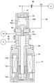
- FIG. 2 is a cross-sectional view showing the configuration of the flow control valve 5.
- the flow control valve 5 includes a valve body 51 that adjusts the opening degree of the air supply passage 35, a pressure-sensitive mechanism 52 that is operatively connected to the valve body 51 at the top of the drawing, An electromagnetic actuator 53 operatively connected to the body 51 at the bottom of the drawing is provided inside the valve housing 54. Inside the valve housing 54, a valve hole 54a constituting a part of the air supply passage 35 is formed. When the valve body 51 moves downward, the opening degree of the valve hole 54a increases, and conversely upwards. The opening degree of the valve hole 54a is reduced by moving to.
- the pressure sensing mechanism 52 is composed of a pressure sensing chamber 52a formed in the upper part of the valve housing 54 and a bellows 52b which is a pressure sensing member accommodated in the pressure sensing chamber 52a.
- the pressure sensitive chamber 52a is partitioned by a bellows 52b into a first pressure chamber 55 that is an internal space of the bellows 52b and a second pressure chamber 56 that is an external space of the bellows 52b.
- the first pressure chamber 55 and the first pressure monitoring point P1 communicate with each other via the first pressure detection passage 57.
- the second pressure chamber 56 and the second pressure monitoring point P2 communicate with each other via the second pressure detection passage 58.
- a fixed throttle portion 36 is formed in the discharge passage 11 to increase the differential pressure ⁇ P between the two points P1 and P2 (ie, PdH ⁇ PdL). ing.
- the pressure loss ie, differential pressure
- the fixed throttle part 36 expands the differential pressure
- the pressure PdH is guided to the first pressure chamber 55, and the pressure PdL is guided to the second pressure chamber 56.
- the bellows 52b applies a downward pressing force to the valve body 51 based on the pressure difference ⁇ Pd between the pressure PdH and the pressure PdL.
- the electromagnetic actuator 53 includes a fixed iron core 53a, a movable iron core 53b, and a coil 53c, and a valve body 51 is operably connected to the movable iron core 53b.
- An upward electromagnetic force corresponding to the amount of electric power supplied to the coil 53c is generated between the fixed iron core 53a and the movable iron core 53b, and is further transmitted to the valve body 51 via the movable iron core 53b.
- a ⁇ ⁇ Pd + B ⁇ ⁇ Pdc + Fspr Fsol (F1)
- Fsol is an upward electromagnetic force that the movable iron core 53b acts on the valve body 51 by energizing the coil 53c.
- a ⁇ ⁇ Pd is a downward pressing force in the drawing based on the differential pressure ⁇ Pd (that is, the differential pressure between the refrigerant in P1 and P2 in FIGS. 1 and 2) that the bellows 52b acts on the valve body 51, and
- A is It is a cross-sectional area of the bellows 52b on which the differential pressure ⁇ Pd acts.
- B ⁇ ⁇ Pdc is a downward pressing force based on the pressure difference ⁇ Pdc between the discharge chamber 9 and the crank chamber 16, and B is a cross-sectional area of the valve body 51 on which the pressure difference ⁇ Pdc acts.
- Fspr is a downward biasing force in the drawing based on a predetermined spring force of the bellows 52b.
- FIG. 3 is a block diagram of a control system in the vehicle air conditioner.
- the vehicle air conditioner includes an indoor air conditioning unit, an air conditioner ECU 100, and a control panel 80.
- the indoor air conditioning unit is disposed between the back of the instrument panel in the passenger compartment and the engine room.
- the air conditioner ECU 100 can automatically control the units 90 to 93 (that is, various doors, blowers, etc.) of the indoor air conditioning unit and the flow control valve 5 that is a component of the refrigeration cycle apparatus 60 for the vehicle.
- the control panel 80 is operated by a passenger to set a desired driving.
- the air conditioner ECU 100 When the air conditioner ECU 100 receives a command signal transmitted from the control panel 80, the air conditioner ECU 100 can perform an air conditioning operation by performing a calculation according to a predetermined program.
- the air conditioner ECU 100 includes a microcomputer 101, an input circuit 102, and an output circuit 103. To the input circuit 102, signals from various switches on the control panel 80 provided in the front of the vehicle interior and sensor signals from the various sensors 40, 81 to 87 are input.
- the output circuit 103 sends output signals to the various actuators M1 to M4 and sends capacity control signals to the flow control valve 5.
- the microcomputer 101 includes a ROM (ie, a read-only storage device), a memory such as a RAM (ie, a read / write storage device), a CPU (ie, a central processing unit), and the like.
- the microcomputer 101 has various programs used for calculation based on the operation command transmitted from the control panel 80 or the like. Equation 1 is also included in these programs.
- the control panel 80 is provided with an air conditioner switch, a suction port changeover switch, a temperature setting switch, an air volume changeover switch, an air outlet changeover switch, and the like.
- the air conditioner switch is a switch for instructing start and stop of the compressor 1.
- the suction port changeover switch is a switch for switching the suction port mode.
- the temperature setting switch is a switch for setting the passenger compartment temperature.
- the air volume changeover switch is a switch for changing the air flow rate to the vehicle interior by the blower 93.
- a blower outlet changeover switch is a switch for switching blower outlet mode.
- Various sensors include an inside air temperature sensor 81, an outside air temperature sensor 82, a solar radiation sensor 83, a post-evaporator temperature sensor 84, a water temperature sensor 85, a discharge pressure sensor 86, a discharge temperature sensor 87, a flow rate sensor 40, an engine speed sensor 88, and the like. Including.
- the inside air temperature sensor 81 detects the air temperature inside the passenger compartment, and the outside air temperature sensor 82 detects the outside air temperature outside the passenger compartment.
- the solar radiation sensor 83 detects the amount of solar radiation irradiated into the passenger compartment, and the post-evaporator temperature sensor 84 detects the fin temperature of the heat exchange core portion in the evaporator 4.
- the water temperature sensor 85 detects the cooling water temperature to the heater that heats the blown air inside the indoor air conditioning unit, and the discharge pressure sensor 86 detects the discharge-side refrigerant pressure Pd discharged from the compressor 1. It is.
- the discharge pressure sensor 86 detects the discharge side refrigerant pressure Pd discharged from the compressor 1, and the discharge temperature sensor 87 detects the discharge side refrigerant temperature Td discharged from the compressor 1.
- the flow sensor 40 is formed by the discharge pipe 13 by detecting a differential pressure between the refrigerant on the upstream side and the refrigerant on the downstream side of the refrigerant passage formed by the discharge pipe 13 connecting the compressor 1 and the heat exchanger 2. The flow rate of the refrigerant flowing through the refrigerant passage is detected.
- the engine speed sensor 88 detects the engine speed Nc. Detection signals from these sensors are input to the air conditioner ECU 100.
- the post-evaporator temperature sensor 84 is an example of an evaporator temperature detection unit that detects the outlet side temperature of the evaporator 4.
- the post-evaporator temperature sensor 84 is a fin temperature sensor provided by being inserted between the fins of the heat exchange core portion of the evaporator 4.
- a post-evaporator air temperature sensor that detects the air temperature immediately after passing through the heat exchange core unit of the evaporator 4 may be used.
- the microcomputer 101 includes a memory such as a ROM and a RAM, a CPU, and the like, and has various programs used for calculations based on an operation command transmitted from the control panel 80 or the like.
- a signal output from the microcomputer 101 is D / A converted, amplified, and the like by the output circuit 103 and then output as a drive signal to the various actuators M1, M2, M3, M4 and the flow rate control valve 5.
- Actuators M 1, M 2, M 3, and M 4 drive each of the outlet switching door 90, the inside / outside air switching door 91, the air mix door 92, and the blower 93.
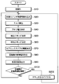
- FIG. 4 is a flowchart showing an air conditioning control process by the air conditioner ECU 100.
- an auto air conditioning operation command is input to the air conditioner ECU 100, for example, when the air conditioner switch is turned on. Then, the air conditioner ECU 100 starts the air conditioning control process according to the air conditioning control process shown in FIG. Then, the control program stored in the memory such as ROM or RAM starts, and the data stored in the RAM is initialized in step S10.
- step S20 the air conditioner ECU 100 controls the control panel 80, the inside air temperature sensor 81, the outside air temperature sensor 82, the solar radiation sensor 83, the post-evaporator temperature sensor 84, the water temperature sensor 85, the discharge pressure sensor 86, the flow rate sensor 40, the discharge temperature. Signals from the sensor 87 and the engine speed sensor 88 are read.
- a target blowing temperature TAO which is a target value of the temperature of the air blown into the passenger compartment, is calculated by data based on these signals and a program (that is, an arithmetic expression) stored in the ROM. Specifically, the target blowing temperature TAO is calculated using the following formula F2.
- TAO Kset ⁇ Tset ⁇ Kr ⁇ Tr ⁇ Kam ⁇ Tam ⁇ Ks ⁇ As + C (F2)
- Tset is a target temperature in the vehicle interior set by the temperature setting switch
- Tr is a detection signal detected by the inside air temperature sensor 81
- Tam is a detection signal detected by the outside air temperature sensor 82
- As is a solar radiation sensor 83. The detected signal detected is shown.
- Kset, Kr, Kam, and Ks are control gains, and C is a correction constant.
- step S40 the air conditioner ECU 100 determines a voltage for operating the blower 93 that supplies air to the vehicle interior.
- This blower voltage determination process is calculated using a characteristic diagram stored in advance in the ROM.
- step S50 the air conditioner ECU 100 executes a process of determining a suction port mode corresponding to the target outlet temperature TAO calculated in step S30.
- the air conditioner ECU 100 determines the suction port mode using a characteristic diagram stored in advance in the ROM. For example, when the target blowing temperature TAO is higher than a predetermined target blowing temperature, the air-conditioning ECU 100 selects the inside air circulation mode and is equal to or lower than the predetermined target blowing temperature. If it is, the outside air introduction mode is selected.
- step S60 the air conditioner ECU 100 determines the outlet mode corresponding to the target outlet temperature TAO calculated in step S30, according to the characteristic chart for determining the outlet mode stored in advance in the ROM, RAM, etc. Execute the process.
- the air conditioner ECU 100 controls to automatically switch the blow mode of the air conditioning zone in the order of the face mode, the bi-level mode, and the foot mode as the target blow temperature TAO increases.
- the face mode is a mode in which conditioned air is blown out only from the face outlet
- the foot mode is a mode in which conditioned air is blown out only from the foot outlet.
- the bar level mode is a mode in which conditioned air is blown out from the face air outlet and the foot air outlet.
- the air conditioner ECU 100 calculates the target opening degree of the air mix door 92 in step S70.
- the degree of opening of the air mix door 92 is determined based on the target blowing temperature TAO calculated in step S30, the fin temperature after the evaporator detected by the post-evaporator temperature sensor 84, and the cooling water temperature detected by the water temperature sensor 85 in the ROM.
- the calculation is performed by substituting into the stored program (that is, the arithmetic expression).
- step S80 the air conditioner ECU 100 calculates a target post-evaporator temperature TEO for realizing the target blowing temperature TAO determined in step S30.
- the target post-evaporator temperature TEO is calculated so that the temperature of the air blown out in the passenger compartment approaches the target blowing temperature TAO.
- feedback control that is, PI control
- a target discharge amount is determined, and further, a control current Ic that satisfies the target discharge amount of the compressor 1 is determined.
- This control current Ic is a current that flows through the coil 53 c of the electromagnetic actuator 53 and corresponds to a capacity control signal that controls the refrigerant discharge capacity of the compressor 1.
- step S90 the air conditioner ECU 100 connects the electromagnetic clutch for power interruption.
- the air conditioner ECU 100 outputs a control signal to the actuators M1 to M4 so as to obtain the control states calculated or determined in the steps S30 to S80, and the control current Ic that satisfies the target discharge amount of the compressor 1 Is output to the flow control valve 5.
- step S100 the air conditioner ECU 100 uses the three conditions of the control current Ic flowing through the coil 53c of the electromagnetic actuator 53, the rotational speed Nc of the compressor 1, and the temperature Td of the refrigerant discharged from the compressor 1 to compress the compressor. It is determined whether 1 is in the high load operation region.
- the following formula F3 is stored in the memory of the air conditioner ECU 100.
- the air conditioner ECU 100 estimates the temperature Tc at a predetermined position of the compressor 1 using the mathematical formula F3, and the compressor 1 is loaded with high load based on whether or not the temperature Tc at the predetermined position of the compressor 1 is equal to or higher than a predetermined value.
- step S100 it is determined whether or not the vehicle is in the operation region.
- Tc f (Ic, Nc, Td) (F3)
- Ic is the control current of the flow control valve 5
- Nc is the rotation speed of the compressor 1
- Td is the refrigerant discharge temperature of the compressor.
- the control current Ic of the flow control valve 5 has a correlation with the load of the compressor 1, the crankcase internal temperature, and the crankcase internal pressure. That is, when the control current Ic increases, the crankcase pressure decreases, the load on the compressor 1 increases, and the crankcase temperature increases. Note that the current value obtained in step S90 can be used as the control current Ic of the flow control valve 5.
- the rotational speed Nc of the drive shaft 23 of the compressor 1 has a correlation with heat generation of a shaft seal device such as a sliding portion such as radial bearings 24a and 24b and a thrust bearing 241 and a mechanical seal. Since the rotational speed Nc of the drive shaft 23 of the compressor 1 is proportional to the engine rotational speed, it can be specified from the output value of the engine rotational speed sensor 88.
- the refrigerant discharge temperature Td of the compressor 1 has a correlation with the load of the compressor 1. That is, the higher the refrigerant discharge temperature Td of the compressor 1, the greater the load on the compressor 1. Further, the refrigerant discharge temperature Td of the compressor 1 has a correlation with the amount of gas filled in the refrigerant in the refrigeration cycle. For example, when the gas filling amount of the refrigerant in the refrigeration cycle decreases due to secular change, the refrigerant temperature Td discharged from the compressor 1 increases.
- the refrigerant discharge temperature Td of the compressor 1 can be specified using the output value of the discharge temperature sensor 87.
- the air conditioner ECU 100 determines whether or not the compressor 1 is in the high load operation region based on whether or not the temperature Tc at the predetermined position of the compressor 1 estimated using the formula F3 is equal to or higher than a predetermined value.
- the process returns to the process of step S20 and the above-described control process of steps S20 to S100 is repeated.
- the temperature Tc at the predetermined position of the compressor 1 estimated using the mathematical formula F3 is equal to or higher than the predetermined value, it is determined YES in S100, and the air conditioner ECU 100 reduces the refrigerant discharge capacity of the compressor 1.
- the control current Ic is reduced. Thereby, the opening degree of the flow control valve 5 increases, the stroke of the piston 29 decreases, and the discharge capacity of the compressor 1 decreases.
- the air conditioner ECU 100 returns to the process of step S20 and repeats the control processes of the above-described steps S20 to S100.
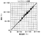
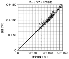
- FIG. 5A is a diagram showing a comparative example between the estimated value and the actually measured value of the crankcase temperature indicated by M1 in FIG.
- FIG. 5B is a diagram showing a comparative example of the estimated value and the actually measured value of the shaft seal temperature indicated by M2 in FIG.
- FIG. 5C is a diagram showing a comparative example between the estimated value and the actually measured value of the pulley bearing temperature indicated by M3 in FIG. As shown in FIGS. 5A to 5C, it was confirmed that the temperature of each part of the compressor was accurately estimated by using Formula F3.
- the vehicle refrigeration cycle apparatus 60 includes the variable displacement compressor 1, the air conditioner ECU 100, and the heat exchanger 2.
- the variable capacity compressor 1 has a discharge capacity variable section that changes the discharge capacity of the refrigerant.
- the air conditioner ECU 100 outputs a capacity control signal for changing the refrigerant discharge capacity to the variable capacity compressor.
- the heat exchanger 2 cools the refrigerant discharged from the variable capacity compressor 1.
- the vehicle refrigeration cycle apparatus 60 is based on an expansion valve 3 that decompresses and expands the refrigerant that flows out of the heat exchanger 2, an evaporator 4 that evaporates the refrigerant decompressed and expanded by the expansion valve 3, and a capacity control signal.
- a high-load determination unit that determines whether or not the compressor is in a high-load operation state.
- the high load determination unit is configured so that the compressor is in a high load operation state based on the capacity control signal and at least one of the rotational speed of the variable capacity compressor and the temperature of the refrigerant discharged from the variable capacity compressor. It is determined whether or not there is. According to this, it is possible to determine whether or not the compressor is in the high load operation state more accurately than in the case of determining whether or not the compressor is in the high load operation state based on the capacity control signal. .
- carbon dioxide is used as a refrigerant. In this way, when carbon dioxide is employed as the refrigerant, it can be determined whether or not it is in a high-load operation state with particularly high accuracy.
- the compressor 1 includes a current-driven coil 53c and a flow rate control valve 5 whose opening degree changes in accordance with a control current that drives the coil 53c, and according to the opening degree of the flow rate control valve 5.
- the refrigerant discharge capacity can be changed.
- the refrigeration cycle apparatus 60 for a vehicle can be applied to a vehicle air conditioner mounted on a vehicle.
- a vehicle refrigeration cycle apparatus 60 according to a second embodiment will be described.
- the vehicular refrigeration cycle apparatus 60 of the present embodiment is the same as the apparatus of the first embodiment.
- the vehicle refrigeration cycle apparatus 60 of the present embodiment differs from the apparatus of the first embodiment in the processing of the air conditioner ECU 100.
- FIG. 6 is a flowchart showing an air conditioning control process of the air conditioner ECU 100 of the present embodiment. Steps S10 to S100 are the same as those in FIG. 4, and thus the description thereof is omitted here.
- the air conditioner ECU 100 determines that the compressor 1 is in the high load operation region based on whether or not the temperature Tc at the predetermined position of the compressor 1 estimated using the mathematical formula F3 in step S100 is equal to or higher than a predetermined value. It is determined whether or not.
- step S20 if the temperature at the predetermined position of the compressor is lower than the predetermined value, the process returns to step S20 and the control processes of steps S20 to S100 described above are repeated.
- the temperature Tc at the predetermined position of the compressor 1 estimated using the mathematical formula F3 is equal to or higher than the predetermined value, it is determined YES in S100, and the air conditioner ECU 100 turns off the electromagnetic clutch 38 of the compressor 1 in step S202. And return to Step S20.
- the pulley 380 and the hub 343 are disconnected, the transmission of the rotational driving force from the engine to the compressor 1 is disconnected, and the compressor 1 enters a no-load state. Thereafter, the process returns to step S20.
- variable displacement compressor with a clutch has been described as an example.
- a clutchless variable displacement compressor such as a so-called DL pulley compressor is used. May be adopted.
- the compressor 1 is operated at a high load using Formula F3 using the control current Ic of the flow control valve 5, the rotation speed Nc of the compressor 1, and the refrigerant discharge temperature Td as variables. Judgment whether or not it is in the area. On the other hand, whether or not the compressor 1 is in the high load operation region using at least one of the control current Ic of the flow control valve 5, the rotation speed Nc of the compressor 1, and the discharge temperature Td of the refrigerant of the compressor. You may make it determine.
- the temperature Tc at the predetermined position of the compressor 1 is estimated using the formula F3, and the compressor is determined based on whether the temperature Tc at the predetermined position of the compressor 1 is equal to or higher than a predetermined value. Whether or not 1 is in the high-load operation region is determined. However, it is not always necessary to estimate the temperature Tc at a predetermined position of the compressor 1, and a function having the control current Ic of the flow control valve 5, the rotational speed Nc of the compressor 1, and the refrigerant discharge temperature Td as variables is used. It may be used to determine whether or not the compressor 1 is in the high load operation region.
- the control current flowing through the coil 53c of the flow control valve 5 is a capacity control signal for controlling the refrigerant discharge capacity of the compressor 1.
- a signal other than the control current that flows through the coil 53c of the flow control valve 5 such as a swash plate angle detection sensor or a crank chamber pressure may be estimated.
- the refrigeration cycle apparatus for a vehicle includes a variable capacity compressor having a discharge capacity variable unit that changes the discharge capacity of the refrigerant, and discharge of the refrigerant.
- a controller that outputs a capacity control signal for changing the capacity to the variable capacity compressor, a heat exchanger that condenses or cools the refrigerant discharged from the variable capacity compressor, and decompresses and expands the refrigerant that flows out of the heat exchanger A decompression unit; an evaporator that evaporates the refrigerant decompressed and expanded by the decompression unit; and a high load determination unit that determines whether the compressor is in a high load operation state based on a capacity control signal.
- the high load determination unit is configured to compress the compressor based on the capacity control signal and at least one of the rotational speed of the variable capacity compressor and the temperature of the refrigerant discharged from the variable capacity compressor. Determines whether or not is in a high-load operation state. According to this, it is possible to determine whether or not the compressor is in the high load operation state more accurately than in the case of determining whether or not the compressor is in the high load operation state based on the capacity control signal. .
- the high load determination unit determines whether the compressor is high based on the capacity control signal, the rotational speed of the variable capacity compressor, and the temperature of the refrigerant discharged from the variable capacity compressor. It is determined whether or not it is in a load operation state. According to this, it is possible to determine whether or not the compressor is in the high load operation state more accurately than in the case of determining whether or not the compressor is in the high load operation state based on the capacity control signal. .
- carbon dioxide is adopted as the refrigerant.
- carbon dioxide when carbon dioxide is employed as the refrigerant, it can be determined whether or not it is in a high-load operation state with particularly high accuracy.
- the compressor has a current-driven coil and a flow rate control valve whose opening degree changes in accordance with a control current that drives the coil, and according to the opening degree of the flow rate control valve.
- the refrigerant discharge capacity is changed.
- the vehicle refrigeration cycle apparatus is applied to a vehicle air conditioner mounted on a vehicle.
Landscapes
- Engineering & Computer Science (AREA)
- Mechanical Engineering (AREA)
- General Engineering & Computer Science (AREA)
- Physics & Mathematics (AREA)
- Thermal Sciences (AREA)
- Air-Conditioning For Vehicles (AREA)
- Control Of Positive-Displacement Pumps (AREA)
- Compressors, Vaccum Pumps And Other Relevant Systems (AREA)
Abstract
冷凍サイクル装置は、冷媒の吐出容量を変化させる吐出容量可変部を有する可変容量型圧縮機(1)と、前記冷媒の吐出容量を変化させる容量制御信号を前記可変容量型圧縮機へ出力する制御部(100)と、前記可変容量型圧縮機から吐出した前記冷媒を凝縮または冷却する熱交換器(2)と、前記熱交換器から流出した前記冷媒を減圧膨張させる減圧部(3)と、前記減圧部により減圧膨張された前記冷媒を蒸発させる蒸発器(4)と、前記容量制御信号に基づいて前記圧縮機が高負荷運転状態であるか否かを判定する高負荷判定部(S100)と、を備える。
Description
本出願は、2016年3月22日に出願された日本特許出願番号2016-57495号に基づくもので、ここにその記載内容が参照により組み入れられる。
本開示は、冷媒の吐出容量を変化させる吐出容量可変部を有する可変容量型圧縮機を有する冷凍サイクル装置に関するものである。
この種の圧縮機は、ハウジングと駆動軸の隙間からハウジングの外部へ冷媒や潤滑オイルが漏れ出すのを防止するリップシールやメカニカルシール等の軸封装置を備えている。また、このような圧縮機は、スラスト軸受、ラジアル軸受等の多数の摺動部材も備えている。
これらの軸封装置や摺動部材は、高温になると耐摩耗性や焼き付け性に問題が生じる。特に、冷媒として二酸化炭素を採用した場合、圧縮機の吐出冷媒温度は高温となり、それに伴い軸封装置や摺動部材の環境温度も高温となる。このため、軸封装置や摺動部材の環境温度が高温となったときに軸封装置や摺動部材を保護することが重要となっている。
そこで、圧縮機の出口と凝縮器またはガスクーラの入口を接続する配管のいずれかの部位における冷媒の圧力を検知する高圧圧力センサを備えることが、例えば、特許文献1に記載されている。そして特許文献1には、高圧圧力センサで検知された圧力が所定の閾値を超えると吐出容量を減少させて高負荷運転領域を回避することが記載されている。
上記特許文献1に記載された装置は、圧縮機の冷媒の吐出圧力が所定の閾値を超えると吐出容量を減少させるように制御している。ところが、本発明者等の検討によれば、冷媒として二酸化炭素を用いた冷凍サイクルに用いられる圧縮機では、圧縮機の吐出圧力と摺動部材の温度との間の相関が低いことが分かった。これは、冷媒として二酸化炭素を用いた冷凍サイクルでは、冷媒の吐出圧力を一定に維持するような制御が行われることが多いためと考えられる。
したがって、上記特許文献1に記載された圧縮機において、冷媒として二酸化炭素を採用した場合、圧縮機の高負荷運転領域を精度良く判定することが難しい。
本開示は、冷媒の吐出圧力を用いることなく、精度良く圧縮機の高負荷運転状態を判定することを目的とする。
本開示の1つの観点によれば、車両用冷凍サイクル装置は、冷媒の吐出容量を変化させる吐出容量可変部を有する可変容量型圧縮機と、冷媒の吐出容量を変化させる容量制御信号を可変容量型圧縮機へ出力する制御部と、可変容量型圧縮機から吐出した冷媒を凝縮または冷却する熱交換器と、熱交換器から流出した冷媒を減圧膨張させる減圧部と、減圧部により減圧膨張された冷媒を蒸発させる蒸発器と、容量制御信号に基づいて圧縮機が高負荷運転状態であるか否かを判定する高負荷判定部と、を備えている。
これによれば、冷媒の吐出圧力を用いることなく、精度良く圧縮機の高負荷運転状態を判定することができる。
以下、図面を参照しながら本開示に係る複数の形態を説明する。各形態において先行する形態で説明した事項に対応する部分には同一の参照符号を付して重複する説明を省略する場合がある。各形態において構成の一部のみを説明している場合は、構成の他の部分については先行して説明した形態と同様とする。実施の各形態で具体的に説明している部分の組合せばかりではなく、特に組合せに支障が生じなければ、実施の形態同士を部分的に組み合せることも可能である。
(第1実施形態)
第1実施形態に係る車両用冷凍サイクル装置60について、図1~図4、図5A~図5Cを用いて説明する。図1は、本実施形態における車両用冷凍サイクル装置60の概略構成およびその一構成部品である圧縮機1の内部構成を示した概略図である。
第1実施形態に係る車両用冷凍サイクル装置60について、図1~図4、図5A~図5Cを用いて説明する。図1は、本実施形態における車両用冷凍サイクル装置60の概略構成およびその一構成部品である圧縮機1の内部構成を示した概略図である。
車両用空調装置に用いられる車両用冷凍サイクル装置60は、圧縮機1と、熱交換器2と、膨張弁3と、蒸発器4とを備えており、これらを環状に接続して構成されている。圧縮機1は、吸入した冷媒を高圧にして吐出する。熱交換器2は、圧縮機1から吐出した冷媒を凝縮または冷却する。膨張弁3は、熱交換器2から流出した冷媒を減圧膨張させる減圧部である。蒸発器4は、膨張弁3により減圧膨張された冷媒を蒸発気化させる。なお、熱交換器2は、凝縮器またはガスクーラを用いて構成することができる。また、本実施形態の車両用冷凍サイクル装置60では、冷媒として二酸化炭素を採用している。
圧縮機1は、冷媒の吐出容量を変化させる吐出容量可変部を有し、冷媒の流量制御機構である流量制御弁5によって冷媒の吐出容量が制御される。なお、吐出容量可変部は、後述する斜板26、流量制御弁5等により構成される。圧縮機1のシリンダブロック6のリア側端面には、バルブプレート7を介してリアハウジング8が接合されている。その内部には吐出室9、吸入室10、吐出室9と接続されている吐出通路11、および吸入室10と接続されている吸入通路12が設けられている。吐出通路11は吐出管13によって熱交換器2と連結されており、吸入通路12は吸入管14によって蒸発器4と連結されている。
圧縮機1と熱交換器2との間で吐出管13により形成される冷媒通路には、2点間の流量差圧を得るための固定絞り部39と、差圧検出部としての流量センサ40とが設けられている。流量センサ40は固定絞り部39の上流側の高圧側冷媒と下流側の低圧側冷媒の流量差圧(すなわちPdL-PdLL)を精度よく検出することができる。この流量差圧は、高圧側冷媒における第2圧力監視点P2と低圧側冷媒における第3圧力監視点P3の流量差圧である。この流量差圧(すなわちPdL-PdLL)は、後述する第1圧力監視点P1と第2圧力監視点P2の二点間差圧△P(すなわちPdH-PdL)にほぼ等しい。
流量センサ40は、その構造の詳細は図示されていないが、高圧側通路40aと、低圧側通路40bと、可動体と、コイルスプリングと、磁石と、位置センサと、を備えて構成されている。高圧側通路40aは、高圧側冷媒が流れる第2圧力監視点P2を含む吐出通路11に固定絞り部39の上流側で連通する。低圧側通路40bは、低圧側冷媒が流れる第3圧力監視点P3を含む通路に固定絞り部39の下流側で連通する。可動体は、高圧側通路40a内で摺動するスプールからなる。コイルスプリングは、当該可動体を高圧側通路40a側に付勢する。磁石は、可動体の先端部に設けられる。位置センサは、この磁石と対向して配置されて当該可動体の変位を検出する。
流量制御弁5は、本空調装置の制御部に対応する図3のエアコンECU100によって制御される。流量制御弁5については後で詳細に説明する。
圧縮機1は、不図示のエンジンの動力を駆動軸23に伝達する電磁クラッチ38を有している。電磁クラッチ38は、プーリ380、ハブ343およびプーリベアリング382を有している。プーリ380は、不図示のエンジンから不図示のVベルトを介して与えられる回転駆動力によって回転する駆動側回転体を構成する。ハブ343は、略円盤状を成しており、圧縮機1の駆動軸23と一体で回転するとともに圧縮機1の駆動軸23の軸方向に相対移動する。ハブ343は、圧縮機1の駆動軸23に連結された受動側回転体を構成する。電磁クラッチ38は、プーリ380とハブ343とを連結あるいは切り離すことで、エンジンから圧縮機1への回転駆動力の伝達を断続するものである。
プーリベアリング382は、プーリ380とフロントハウジング15との間に介装されており、フロントハウジング15に対してプーリ380を回転可能に支持している。
電磁クラッチ38への通電はエアコンECU100によって断続され、電磁クラッチ38が通電されてプーリ380とハブ343とが連結状態になると、圧縮機1は運転状態となり、電磁クラッチ38の通電が遮断されてプーリ380とハブ343とが開離状態になると、圧縮機1は停止する。
次に、圧縮機1の内部構成を図1にしたがって説明する。圧縮機1のシリンダブロック6のフロント側端面には、フロントハウジング15が接合されている。フロントハウジング15の内部には区画されたクランク室16が形成されている。シリンダブロック6とバルブプレート7との間には、吸入弁17と一体になっている吸入弁形成板18が設けられている。バルブプレート7とリアハウジング8との間には、吐出弁19と一体になっている吐出弁形成板20と、リテーナ21を構成するリテーナ形成板22とが設けられている。シリンダブロック6、フロントハウジング15およびリアハウジング8はスルーボルトによって締付け固定されて一体になっている。
駆動軸23は、シリンダブロック6とフロントハウジング15の中心部に形成された軸孔にラジアル軸受24a、24bを介して回転可能に支持されている。駆動軸23は、不図示のVベルト、電磁クラッチ38を介してエンジンに作動可能に連結されており、エンジンからの動力供給を受けて回転する。駆動軸23は、クランク室16において回転可能なラグプレート25が一体に固定されており、カムプレートである斜板26は駆動軸23が挿通された状態で配置されている。
ラグプレート25と斜板26はヒンジ機構27によって連結されている。ヒンジ機構27は、斜板26側に向かうようにラグプレート25に突設された2つのラグプレート側突起25aと、ラグプレート25側に向かうように斜板26に突設された斜板側突起26aとによって構成されている。斜板側突起26aは、先端側が2つのラグプレート側突起25a間に入り込むように配置されている。ラグプレート25の回転力はラグプレート側突起25aおよび斜板側突起26aを介して斜板26に伝達される。
したがって斜板26は、ラグプレート25との間でヒンジ機構27による連結と、駆動軸23による支持とにより、ラグプレート25および駆動軸23と同期して回転可能であり、さらに駆動軸23の軸線方向へのスライド移動を伴いながら駆動軸23に対して傾動可能となっている。また、ラグプレート25は、フロントハウジング15に対してスラスト軸受241を介して回転自在に指示されている。
また、駆動軸23とフロントハウジング15の間には、メカニカルシール240が設けられている。このメカニカルシール240は、フロントハウジング15と駆動軸23の隙間からフロントハウジング15の外部へ冷媒が漏れ出すのを防止している。
シリンダブロック6の内部に周方向に配設されている複数のシリンダボア28の各々には、ピストン29が往復動可能に収容されている。各ピストン29の一端側とバルブプレート7との間には、ピストン29の往復運動に応じて容積変化する圧縮室30が形成されている。ピストン29の他端側は、シュー31を介して斜板26の周縁部に支持されている。
上記構成によって、エンジンの動力がVベルト、電磁クラッチ38を介して駆動軸23に伝達し、駆動軸23が回転すると、ラグプレート25およびヒンジ機構27を介して斜板26が回転し、シュー31を介してピストン29がシリンダボア28内で往復運動する。ピストン29の吸入工程時には、蒸発器4から吸入室10内に導入された冷媒ガスが吸入ポート32を通過して吸入弁17を押しのけ、さらに圧縮室30に吸入される。そしてピストン29が圧縮、吐出工程に移行すると、圧縮室30内の冷媒ガスは吐出ポート33を通って吐出弁19を押しのけ、吐出室9に吐出されることになる。
シリンダブロック6およびリアハウジング8の内部には、クランク室16と吸入室10とを連通する抽気通路34、および吐出室9とクランク室16とを連通する給気通路35が設けられている。流量制御弁5は、リアハウジング8の内部であって給気通路35の途中に設けられている。
エアコンECU100から出力される容量制御信号に応じて流量制御弁5の開度が調節されると、給気通路35を介したクランク室16への高圧の吐出冷媒ガスの導入量と抽気通路34を介したクランク室16からの冷媒ガスの導出量とのバランスが制御され、クランク室16の内圧が決定されることになる。クランク室16の内圧の変化に応じて、ピストン29を介してのクランク室16の内圧と圧縮室30の内圧との差が変化すると、斜板26の傾斜角度が変わり、圧縮機1の吐出容量が調節される。
エアコンECU100から出力される容量制御信号に応じて流量制御弁5の開度が小さくなると、クランク室16の内圧は低下する。そして、クランク室16の内圧が低下すると、斜板26の傾斜角度が増大し、圧縮機1の吐出容量が増大する。図1では、斜板26のそれ以上の傾動がラグプレート25によって規制された最大傾斜角度の状態を示している。
逆にエアコンECU100から出力される容量制御信号に応じて流量制御弁5の開度が大きくなると、クランク室16の内圧は上昇する。そして、クランク室16の内圧が上昇すると、斜板26の傾斜角度が小さくなりピストン29のストロークが減少し、圧縮機1の吐出容量が減少することになる。このように斜板26の傾斜角度を変えて圧縮機1の吐出容量を調節することにより、車室内の冷房を最適な状態にするようになっている。
次に、流量制御弁5の構成を図2にしたがって説明する。図2は流量制御弁5の構成を示した断面図である。図2に示すように、流量制御弁5は、給気通路35の開度を調節する弁体51と、弁体51に図面上方で作動可能に連結されている感圧機構部52と、弁体51に図面下方で作動可能に連結されている電磁アクチュエータ53と、をバルブハウジング54の内部に備えている。バルブハウジング54の内部には、給気通路35の一部を構成する弁孔54aが形成されており、弁体51が下方に移動することによって弁孔54aの開度が増大し、逆に上方に移動することによって弁孔54aの開度が小さくなる。
感圧機構部52は、バルブハウジング54内の上部に形成された感圧室52aと、感圧室52a内に収容された感圧部材であるベローズ52bとから構成されている。感圧室52aは、ベローズ52bによってベローズ52bの内部空間である第1圧力室55と、ベローズ52bの外部空間である第2圧力室56と、に区画されている。第1圧力室55と第1圧力監視点P1とは第1検圧通路57を介して連通している。また、第2圧力室56と第2圧力監視点P2とは第2検圧通路58を介して連通している。
第1圧力監視点P1と第2圧力監視点P2との間には、P1とP2の二点間差圧△P(すなわちPdH-PdL)を拡大する固定絞り部36が吐出通路11に形成されている。冷凍サイクルを流れる冷媒の流量が多くなるほど、単位長さ当りの圧力損失(すなわち差圧)は大きくなる。つまり、2つの圧力監視点P1、P2間の差圧(以下、二点間差圧△Pとする)を把握することによって、冷凍サイクルにおける冷媒流量を間接的に検出することができる。そして、固定絞り部36は二点間差圧△Pを拡大するようにすると、冷媒流量の検出をより明確にすることができる。
上記構成により、感圧機構部52において、第1圧力室55には圧力PdHが導かれ、第2圧力室56には圧力PdLが導かれる。ベローズ52bは、圧力PdHと圧力PdLとの差圧△Pdに基づく図面下向きの押圧力を弁体51に作用させる。
電磁アクチュエータ53は、固定鉄心53a、可動鉄心53bおよびコイル53cから構成されており、可動鉄心53bには弁体51が作動可能に連結されている。コイル53cに供給される電力量に応じた図面上向きの電磁力は固定鉄心53aと可動鉄心53bとの間に発生し、さらに可動鉄心53bを介して弁体51に伝達される。
流量制御弁5においては、次の数式1に示す力のつりあいが成り立ち、これらの力がつりあうところで弁体51の位置が決定される。この数式F1は、エアコンECU100のマイクロコンピュータ101に予め記憶されている。
A×△Pd + B×ΔPdc + Fspr = Fsol…(F1)
Fsolはコイル53cへの通電により可動鉄心53bが弁体51に作用させる図面上向きの電磁力である。A×△Pdはベローズ52bが弁体51に作用させる差圧△Pd(すなわち、図1や図2のP1における冷媒とP2における冷媒との差圧)に基づく図面下向き押圧力であり、Aは差圧△Pdが作用するベローズ52bの断面積である。B×ΔPdcは、吐出室9とクランク室16との差圧△Pdcに基づく図面下向き押圧力であり、Bは差圧ΔPdcが作用する弁体51の断面積である。Fsprはベローズ52bの所定のバネ力に基づく図面下向き付勢力である。
Fsolはコイル53cへの通電により可動鉄心53bが弁体51に作用させる図面上向きの電磁力である。A×△Pdはベローズ52bが弁体51に作用させる差圧△Pd(すなわち、図1や図2のP1における冷媒とP2における冷媒との差圧)に基づく図面下向き押圧力であり、Aは差圧△Pdが作用するベローズ52bの断面積である。B×ΔPdcは、吐出室9とクランク室16との差圧△Pdcに基づく図面下向き押圧力であり、Bは差圧ΔPdcが作用する弁体51の断面積である。Fsprはベローズ52bの所定のバネ力に基づく図面下向き付勢力である。
次に、車両用冷凍サイクル装置60を使用する車両用空調装置の制御システムについて説明する。図3は、当該車両用空調装置における制御システムのブロック図である。図3に示すように、当該車両用空調装置は、室内空調ユニットと、エアコンECU100と、コントロールパネル80と、を備えている。室内空調ユニットは、車室内のインストルメントパネル裏面とエンジンルームとの間に配置される。エアコンECU100は、室内空調ユニットの各部90~93(すなわち各種ドア、ブロワ等)および車両用冷凍サイクル装置60の構成部品である流量制御弁5等を自動制御可能である。コントロールパネル80は、所望の運転を設定するために乗員によって操作される。
エアコンECU100は、コントロールパネル80から送信される命令信号を受信すると、所定のプログラムによる演算を行って空調運転を実行することができる。エアコンECU100は、マイクロコンピュータ101と、入力回路102と、出力回路103と、を備えている。入力回路102には、車室内前面に設けられたコントロールパネル80上の各種スイッチからの信号および各種センサ40、81~87からのセンサ信号が入力される。出力回路103は、各種アクチュエータM1~M4に出力信号を送るとともに流量制御弁5に容量制御信号を送る。
マイクロコンピュータ101は、ROM(すなわち読み込み専用記憶装置)、RAM(すなわち読み込み書き込み可能記憶装置)等のメモリおよびCPU(すなわち中央演算装置)等から構成されている。マイクロコンピュータ101は、コントロールパネル80等から送信された運転命令に基づいた演算に使用される各種プログラムを有している。数式1もこれらプログラムに含まれる。
コントロールパネル80には、エアコンスイッチ、吸込口切替スイッチ、温度設定スイッチ、風量切替スイッチ、吹出口切替スイッチ等が設けられている。エアコンスイッチは、圧縮機1の起動および停止を命令するためのスイッチである。吸込口切替スイッチは、吸込口モードを切り替えるためのスイッチである。温度設定スイッチは、車室内温度を設定するためのスイッチである。風量切替スイッチは、ブロワ93による車室内への送風量を切り替えるためのスイッチである。吹出口切替スイッチは、吹出口モードを切り替えるためのスイッチである。
各種センサは、内気温センサ81、外気温センサ82、日射センサ83、蒸発器後温度センサ84、水温センサ85、吐出圧センサ86、吐出温度センサ87、流量センサ40およびエンジン回転数センサ88等を含む。
内気温センサ81は、車室内の空気温度を検出するものであり、外気温センサ82は、車室外の外気温度を検出するものである。日射センサ83は、車室内に照射される日射量を検出するものであり、蒸発器後温度センサ84は、蒸発器4における熱交換コア部のフィン温度を検出するものである。水温センサ85は、室内空調ユニット内部の送風空気を加熱するヒータへの冷却水温度を検出するものであり、吐出圧センサ86は、圧縮機1から吐出される吐出側冷媒圧力Pdを検出するものである。吐出圧センサ86は、圧縮機1から吐出される吐出側冷媒圧力Pdを検出するものであり、吐出温度センサ87は、圧縮機1から吐出される吐出側冷媒温度Tdを検出するものである。流量センサ40は、圧縮機1と熱交換器2との間を接続する吐出管13により形成される冷媒通路の上流側の冷媒と下流側の冷媒の差圧を検出して吐出管13により形成される冷媒通路を流れる冷媒の流量を検出するものである。エンジン回転数センサ88は、エンジンの回転数Ncを検出するものである。これらセンサの検出信号は、エアコンECU100へ入力されるようになっている。
なお、蒸発器後温度センサ84は、蒸発器4の出口側温度を検出する蒸発器温度検出部の一例である。蒸発器後温度センサ84は、蒸発器4の熱交換コア部のフィン間に差し込んで設けられるフィン温度センサである。しかし、蒸発器温度検出部の他の例として蒸発器4の熱交換コア部を通過した直後の空気温度を検出する蒸発器後空気温度センサを用いてもよい。
マイクロコンピュータ101は、ROM、RAM等のメモリおよびCPU等から構成されており、コントロールパネル80等から送信された運転命令に基づいた演算に使用される各種プログラムを有している。マイクロコンピュータ101から出力された信号は、出力回路103によってD/A変換、増幅等された後に、各種アクチュエータM1、M2、M3、M4および流量制御弁5に駆動信号として出力される。アクチュエータM1、M2、M3、M4は、吹出口切替ドア90、内外気切替ドア91、エアミックスドア92、ブロワ93のそれぞれを駆動する。
次に、エアコンECU100による空調制御処理について図4および図5を用いて説明する。図4は、エアコンECU100による空調制御処理を示したフローチャートである。
まず、エアコンスイッチがオンされるなどして、エアコンECU100にオート空調運転命令が入力される。すると、エアコンECU100は、図4に示す空調制御処理にしたがって空調制御処理を開始する。すると、ROM,RAMなどのメモリに記憶された制御プログラムがスタートして、ステップS10でRAMに記憶されるデータなどが初期化される。
次に、エアコンECU100は、ステップS20でコントロールパネル80、内気温センサ81、外気温センサ82、日射センサ83、蒸発器後温度センサ84、水温センサ85、吐出圧センサ86、流量センサ40、吐出温度センサ87およびエンジン回転数センサ88等からの信号を読み込む。
次に、ステップS30で、これらの信号によるデータとROMに記憶されたプログラム(すなわち演算式)とによって車室内に吹き出す空気の温度の目標値である目標吹出温度TAOを算出する。具体的には、以下の数式F2を用いて目標吹出温度TAOを算出する。
TAO=Kset×Tset-Kr×Tr-Kam×Tam-Ks×As+C…(F2)
ここで、Tsetは温度設定スイッチで設定された車室内の目標温度、Trは内気温センサ81で検出された検出信号、Tamは外気温センサ82で検出された検出信号、Asは日射センサ83で検出された検出信号を示している。なお、Kset、Kr、Kam、およびKsは、制御ゲインであり、Cは、補正用の定数である。
ここで、Tsetは温度設定スイッチで設定された車室内の目標温度、Trは内気温センサ81で検出された検出信号、Tamは外気温センサ82で検出された検出信号、Asは日射センサ83で検出された検出信号を示している。なお、Kset、Kr、Kam、およびKsは、制御ゲインであり、Cは、補正用の定数である。
続いてエアコンECU100は、ステップS40において、車室内への送風を提供するブロワ93を作動するための電圧を決定する。このブロワ電圧の決定処理は、予めROMに記憶された特性図を用いて算出される。
次にエアコンECU100は、ステップS50において、ステップS30で算出された目標吹出温度TAOに対応する吸込口モードを決定する処理を実行する。エアコンECU100は、吸込口モードを予めROMに記憶された特性図を用いて決定し、例えば目標吹出温度TAOが所定の目標吹出温度よりも高いときには内気循環モードを選択し、所定の目標吹出温度以下であるときには外気導入モードを選択する。
次にエアコンECU100は、ステップS60において、予めROM、RAMなどに記憶されている吹出ロモード決定するための特性図にしたがい、ステップS30で算出された目標吹出温度TAOに対応する吹出口モードを決定する処理を実行する。エアコンECU100は、目標吹出温度TAOが上昇するにつれて、空調ゾーンの吹出ロモードをフェイスモード、バイレベルモード、フットモードの順番に自動的に切り替えるように制御する。なお、フェイスモードとは、フェイス吹出口だけから空調風を吹き出すモードであり、フットモードとは、フット吹出口だけから空調風を吹き出しモードである。また、バレベルモードとは、フェイス吹出口およびフット吹出口から空調風を吹き出すモードである。
次にエアコンECU100は、ステップS70において、エアミックスドア92の目標開度を算出する。エアミックスドア92の開度は、ステップS30で算出された目標吹出温度TAO、蒸発器後温度センサ84によって検出された蒸発器後のフィン温度、水温センサ85によって検出された冷却水温を、ROMに記憶されたプログラム(すなわち演算式)に代入して演算することによって算出される。
次にエアコンECU100は、ステップS80において、ステップS30で決定した目標吹出温度TAOを実現するための目標蒸発器後温度TEOを算出する。具体的には、車室内の吹き出される空気の温度が目標吹出温度TAOに近付くように目標蒸発器後温度TEOを算出する。より具体的には、目標蒸発器後温度TEOと蒸発器後温度センサ84の検出値である実際の蒸発器後温度Teとが一致するように、フィードバック制御(すなわちPI制御)によって圧縮機1の目標吐出量を決定し、さらに、圧縮機1の目標吐出量を満たす制御電流Icを決定する。この制御電流Icは、電磁アクチュエータ53のコイル53cに流れる電流であって、圧縮機1の冷媒の吐出容量を制御する容量制御信号に相当する。
次にエアコンECU100は、ステップS90にて、動力断続用の電磁クラッチを接続状態する。それと共にエアコンECU100は、各ステップS30~S80で算出または決定された各制御状態が得られるように、アクチュエータM1~M4に制御信号を出力するとともに、圧縮機1の目標吐出量を満たす制御電流Icを流量制御弁5に出力する。
次に、エアコンECU100はステップS100で、電磁アクチュエータ53のコイル53cに流れる制御電流Ic、圧縮機1の回転数Ncおよび圧縮機1から吐出される冷媒の温度Tdの3つの条件を用いて圧縮機1が高負荷運転領域にあるか否かを判定する。
ここで、エアコンECU100のメモリには、以下の数式F3が記憶されている。エアコンECU100は、この数式F3を用いて圧縮機1の所定位置の温度Tcを推定し、圧縮機1の所定位置の温度Tcが所定値以上であるか否かに基づいて圧縮機1が高負荷運転領域にあるか否かをステップS100で判定する。
Tc=f(Ic、Nc、Td)…(F3)
ここで、Icは流量制御弁5の制御電流、Ncは圧縮機1の回転数、Tdは圧縮機の冷媒の吐出温度である。
ここで、Icは流量制御弁5の制御電流、Ncは圧縮機1の回転数、Tdは圧縮機の冷媒の吐出温度である。
流量制御弁5の制御電流Icは、圧縮機1の負荷、クランクケース内温度およびクランクケース内圧力とも相関関係を有している。すなわち、制御電流Icが大きくなると、クランクケース内圧力が低くなり、圧縮機1の負荷は大きくなり、クランクケース内温度は高くなる。なお、流量制御弁5の制御電流Icは、ステップS90で求めた電流値を用いることができる。
圧縮機1の駆動軸23の回転数Ncは、ラジアル軸受24a、24b、スラスト軸受241等の摺動部やメカニカルシールといった軸封装置の発熱と相関関係を有する。圧縮機1の駆動軸23の回転数Ncは、エンジン回転数と比例するため、エンジン回転数センサ88の出力値から特定することができる。
圧縮機1の冷媒の吐出温度Tdは、圧縮機1の負荷と相関関係を有する。すなわち、圧縮機1の冷媒の吐出温度Tdが高いほど、圧縮機1の負荷も大きくなる。また、圧縮機1の冷媒の吐出温度Tdは、冷凍サイクル内の冷媒のガス封入量と相関関係を有する。例えば、経年変化により冷凍サイクル内の冷媒のガス封入量が減少すると、圧縮機1から吐出される冷媒温度Tdは高くなる。圧縮機1の冷媒の吐出温度Tdは、吐出温度センサ87の出力値を用いて特定することができる。
エアコンECU100は、数式F3を用いて推定した圧縮機1の所定位置の温度Tcが所定値以上であるか否かに基づいて圧縮機1が高負荷運転領域にあるか否かを判定する。
ここで、圧縮機の所定位置の温度Tcが所定値未満の場合、ステップS20の処理に戻り上述のステップS20~ステップS100の制御処理を繰り返す。また、数式F3を用いて推定された圧縮機1の所定位置の温度Tcが所定値以上になると、S100にてYESと判定され、エアコンECU100は、圧縮機1の冷媒の吐出容量を減少させるよう制御電流Icを少なくする。これにより、流量制御弁5の開度は増加し、ピストン29のストロークが減少し、圧縮機1の吐出容量が減少する。
そして、エアコンECU100は、数式F3を用いて推定した圧縮機1の所定位置の温度Tcが所定値未満になると、ステップS20の処理に戻り上述のステップS20~ステップS100の制御処理を繰り返す。
ここで、数式F3を用いた圧縮機1の各部の温度の予測について説明する。図5Aは、図1中のM1で示されるクランクケース温度の推定値と実測値に比較例を示した図である。図5Bは、図1中のM2で示されるシャフトシール温度の推定値と実測値に比較例を示した図である。図5Cは、図1中のM3で示されるプーリベアリング温度の推定値と実測値に比較例を示した図である。図5A~図5Cに示すように、数式F3を用いることで圧縮機の各部の温度を精度よく推定することが確認できた。
上記した構成によれば、車両用冷凍サイクル装置60は、可変容量型圧縮機1と、エアコンECU100と、熱交換器2と、を備えている。可変容量型圧縮機1は、冷媒の吐出容量を変化させる吐出容量可変部を有する。エアコンECU100は、冷媒の吐出容量を変化させる容量制御信号を可変容量型圧縮機へ出力する。熱交換器2は、可変容量型圧縮機1から吐出した冷媒を冷却する。さらに、車両用冷凍サイクル装置60は、熱交換器2から流出した冷媒を減圧膨張させる膨張弁3と、膨張弁3により減圧膨張された冷媒を蒸発させる蒸発器4と、容量制御信号に基づいて圧縮機が高負荷運転状態であるか否かを判定する高負荷判定部と、を備えている。エアコンECU100が、ステップS100を実行することで、処理高負荷判定部に対応する。これによれば、冷媒の吐出圧力を用いることなく、精度良く圧縮機の高負荷運転状態を判定することができる。
また、高負荷判定部は、容量制御信号と、可変容量型圧縮機の回転数および可変容量型圧縮機より吐出される冷媒の温度の少なくとも一方と、に基づいて圧縮機が高負荷運転状態であるか否かを判定する。これによれば、容量制御信号に基づいて圧縮機が高負荷運転状態であるか否かを判定する場合と比較して、さらに精度良く高負荷運転状態であるか否かを判定することができる。
また、冷媒として二酸化炭素を採用している。このように、冷媒として二酸化炭素を採用したときに、特に精度良く高負荷運転状態であるか否かを判定することができる。
また、圧縮機1としては、電流駆動されるコイル53cと、該コイル53cを駆動する制御電流に応じて開度が変化する流量制御弁5を有し、該流量制御弁5の開度に応じて冷媒の吐出容量を変化させるよう構成されたものとすることができる。
また、本車両用冷凍サイクル装置60を、車両に搭載される車両用空調装置に適用することができる。
(第2実施形態)
第2実施形態に係る車両用冷凍サイクル装置60について説明する。本実施形態の車両用冷凍サイクル装置60は、上記第1実施形態の装置と同じである。本実施形態の車両用冷凍サイクル装置60は、上記第1実施形態の装置と比較してエアコンECU100の処理が異なる。
第2実施形態に係る車両用冷凍サイクル装置60について説明する。本実施形態の車両用冷凍サイクル装置60は、上記第1実施形態の装置と同じである。本実施形態の車両用冷凍サイクル装置60は、上記第1実施形態の装置と比較してエアコンECU100の処理が異なる。
図6は、本実施形態のエアコンECU100の空調制御処理を示したフローチャートである。ステップS10~ステップS100は、図4と同様であるので、ここではその説明を省略する。
本実施形態では、エアコンECU100は、ステップS100にて、数式F3を用いて推定した圧縮機1の所定位置の温度Tcが所定値以上であるか否かに基づいて圧縮機1が高負荷運転領域にあるか否かを判定する。
ここで、圧縮機の所定位置の温度が所定値未満の場合、ステップS20の処理に戻り上述のステップS20~ステップS100の制御処理を繰り返す。また、数式F3を用いて推定された圧縮機1の所定位置の温度Tcが所定値以上になると、S100にてYESと判定され、エアコンECU100は、ステップS202で圧縮機1の電磁クラッチ38をオフにし、ステップS20に戻る。これにより、プーリ380とハブ343とが切り離され、エンジンから圧縮機1への回転駆動力の伝達が切断され、圧縮機1は無負荷状態となる。この後、ステップS20の処理に戻る。そして、数式F3を用いて推定された圧縮機1の所定位置の温度Tcが所定値以上となっている場合には、ステップS20に戻る。また、数式F3を用いて推定された圧縮機1の所定位置の温度Tcが所定値未満になると、ステップS20の処理に戻り上述のステップS20~ステップS100の制御処理繰り返す。
本実施形態では、上記第1実施形態と共通の構成から奏される同様の効果を上記第1実施形態と同様に得ることができる。
(他の実施形態)
(1)上記実施形態における車両用冷凍サイクル装置60では、冷媒として二酸化炭素を採用したが、二酸化炭素以外の冷媒を採用した冷凍サイクル装置60に適用することもできる。
(1)上記実施形態における車両用冷凍サイクル装置60では、冷媒として二酸化炭素を採用したが、二酸化炭素以外の冷媒を採用した冷凍サイクル装置60に適用することもできる。
(2)上記各実施形態では、クラッチ付き可変容量型圧縮機を例に説明したが、可変容量型圧縮機であるため、例えば、所謂DLプーリ式圧縮機のようなクラッチレス可変容量型圧縮機を採用してもよい。
(3)上記各実施形態では、流量制御弁5の制御電流Ic、圧縮機1の回転数Nc、圧縮機の冷媒の吐出温度Tdを変数とする数式F3を用いて圧縮機1が高負荷運転領域にあるか否かを判定するようにした。これに対し、流量制御弁5の制御電流Ic、圧縮機1の回転数Nc、圧縮機の冷媒の吐出温度Tdの少なくとも1つを用いて圧縮機1が高負荷運転領域にあるか否かを判定するようにしてもよい。
(4)上記各実施形態では、数式F3を用いて圧縮機1の所定位置の温度Tcを推定し、圧縮機1の所定位置の温度Tcが所定値以上であるか否かに基づいて圧縮機1が高負荷運転領域にあるか否かを判定するようにした。しかし、必ずしも圧縮機1の所定位置の温度Tcを推定する必要はなく、流量制御弁5の制御電流Ic、圧縮機1の回転数Nc、圧縮機の冷媒の吐出温度Tdを変数とする関数を用いて圧縮機1が高負荷運転領域にあるか否かを判定してもよい。
(5)上記各実施形態では、流量制御弁5のコイル53cに流れる制御電流を、圧縮機1の冷媒の吐出容量を制御する容量制御信号とした。しかし、例えば、斜板角度検出センサや、クランク室内圧力など、流量制御弁5のコイル53cに流れる制御電流以外の容量を推定できる信号としてもよい。
なお、本開示は上記した実施形態に限定されるものではなく、適宜変更が可能である。また、上記各実施形態は、互いに無関係なものではなく、組み合わせが明らかに不可な場合を除き、適宜組み合わせが可能である。また、上記各実施形態において、実施形態を構成する要素は、特に必須であると明示した場合および原理的に明らかに必須であると考えられる場合等を除き、必ずしも必須のものではないことは言うまでもない。また、上記各実施形態において、実施形態の構成要素の個数、数値、量、範囲等の数値が言及されている場合、特に必須であると明示した場合および原理的に明らかに特定の数に限定される場合等を除き、その特定の数に限定されるものではない。また、上記各実施形態において、構成要素等の材質、形状、位置関係等に言及するときは、特に明示した場合および原理的に特定の材質、形状、位置関係等に限定される場合等を除き、その材質、形状、位置関係等に限定されるものではない。
(まとめ)
上記実施形態の一部または全部で示された第1の観点によれば、車両用冷凍サイクル装置は、冷媒の吐出容量を変化させる吐出容量可変部を有する可変容量型圧縮機と、冷媒の吐出容量を変化させる容量制御信号を可変容量型圧縮機へ出力する制御部と、可変容量型圧縮機から吐出した冷媒を凝縮または冷却する熱交換器と、熱交換器から流出した冷媒を減圧膨張させる減圧部と、減圧部により減圧膨張された冷媒を蒸発させる蒸発器と、容量制御信号に基づいて圧縮機が高負荷運転状態であるか否かを判定する高負荷判定部と、を備えている。
上記実施形態の一部または全部で示された第1の観点によれば、車両用冷凍サイクル装置は、冷媒の吐出容量を変化させる吐出容量可変部を有する可変容量型圧縮機と、冷媒の吐出容量を変化させる容量制御信号を可変容量型圧縮機へ出力する制御部と、可変容量型圧縮機から吐出した冷媒を凝縮または冷却する熱交換器と、熱交換器から流出した冷媒を減圧膨張させる減圧部と、減圧部により減圧膨張された冷媒を蒸発させる蒸発器と、容量制御信号に基づいて圧縮機が高負荷運転状態であるか否かを判定する高負荷判定部と、を備えている。
第2の観点によれば、高負荷判定部は、容量制御信号と、可変容量型圧縮機の回転数および可変容量型圧縮機より吐出される冷媒の温度の少なくとも一方と、に基づいて圧縮機が高負荷運転状態であるか否かを判定する。これによれば、容量制御信号に基づいて圧縮機が高負荷運転状態であるか否かを判定する場合と比較して、さらに精度良く高負荷運転状態であるか否かを判定することができる。
第3の観点によれば、高負荷判定部は、容量制御信号と、可変容量型圧縮機の回転数と、可変容量型圧縮機より吐出される冷媒の温度と、に基づいて圧縮機が高負荷運転状態であるか否かを判定する。これによれば、容量制御信号に基づいて圧縮機が高負荷運転状態であるか否かを判定する場合と比較して、さらに精度良く高負荷運転状態であるか否かを判定することができる。
第4の観点によれば、冷媒として二酸化炭素を採用している。このように、冷媒として二酸化炭素を採用したときに、特に精度良く高負荷運転状態であるか否かを判定することができる。
第5の観点によれば、圧縮機は、電流駆動されるコイルと、該コイルを駆動する制御電流に応じて開度が変化する流量制御弁を有し、該流量制御弁の開度に応じて冷媒の吐出容量を変化させるよう構成されている。
第6の観点によれば、車両用冷凍サイクル装置は、車両に搭載される車両用空調装置に適用される。
Claims (8)
- 冷凍サイクル装置であって、
冷媒の吐出容量を変化させる吐出容量可変部を有する可変容量型圧縮機(1)と、
前記冷媒の吐出容量を変化させる容量制御信号を前記可変容量型圧縮機へ出力する制御部(100)と、
前記可変容量型圧縮機から吐出した前記冷媒を凝縮または冷却する熱交換器(2)と、
前記熱交換器から流出した前記冷媒を減圧膨張させる減圧部(3)と、
前記減圧部により減圧膨張された前記冷媒を蒸発させる蒸発器(4)と、
前記容量制御信号に基づいて前記圧縮機が高負荷運転状態であるか否かを判定する高負荷判定部(S100)と、を備えた冷凍サイクル装置。 - 前記高負荷判定部は、前記容量制御信号と、前記可変容量型圧縮機の回転数および前記可変容量型圧縮機より吐出される前記冷媒の温度の少なくとも一方と、に基づいて前記圧縮機が高負荷運転状態であるか否かを判定する請求項1に記載の冷凍サイクル装置。
- 前記高負荷判定部は、前記容量制御信号と、前記可変容量型圧縮機の回転数と、前記可変容量型圧縮機より吐出される前記冷媒の温度と、に基づいて前記圧縮機が高負荷運転状態であるか否かを判定する請求項1に記載の冷凍サイクル装置。
- 前記冷媒は二酸化炭素である請求項1ないし3のいずれか1つに記載の冷凍サイクル装置。
- 前記圧縮機は、電流駆動されるコイル(53c)と、該コイルを駆動する制御電流に応じて開度が変化する流量制御弁(5)を有し、該流量制御弁の開度に応じて前記冷媒の吐出容量を変化させるよう構成されており、
前記容量制御信号は、前記制御電流である請求項1ないし4のいずれか1つに記載の冷凍サイクル装置。 - 車両に搭載される車両用空調装置に適用されるものである請求項1ないし5のいずれか1つに記載の冷凍サイクル装置
- 動力を前記可変容量型圧縮機の駆動軸(23)に伝達するクラッチ(38)を、前記圧縮機が高負荷運転状態であると前記高負荷判定部が判定したことに基づいて、オフする請求項1ないし6のいずれか1つに記載の冷凍サイクル装置。
- 前記可変容量型圧縮機は、回転する斜板(26)を有し、
前記斜板が回転すると、吸入室(10)内に導入された冷媒が圧縮室(30)を通って吐出室(9)に吐出され、
前記流量制御弁は、前記吸入室と連通するクランク室(16)と前記吐出室とを連通する給気通路(35)の開度を調節する弁体(51)と、前記弁体(51)に連結されている電磁アクチュエータ(53)とを備える請求項5に記載の冷凍サイクル装置。
Priority Applications (3)
| Application Number | Priority Date | Filing Date | Title |
|---|---|---|---|
| DE112017001465.4T DE112017001465T5 (de) | 2016-03-22 | 2017-03-10 | Kältekreislaufvorrichtung |
| US16/086,354 US20190092130A1 (en) | 2016-03-22 | 2017-03-10 | Refrigeration cycle device |
| JP2018507221A JP6593526B2 (ja) | 2016-03-22 | 2017-03-10 | 冷凍サイクル装置 |
Applications Claiming Priority (2)
| Application Number | Priority Date | Filing Date | Title |
|---|---|---|---|
| JP2016057495 | 2016-03-22 | ||
| JP2016-057495 | 2016-03-22 |
Publications (1)
| Publication Number | Publication Date |
|---|---|
| WO2017163935A1 true WO2017163935A1 (ja) | 2017-09-28 |
Family
ID=59900179
Family Applications (1)
| Application Number | Title | Priority Date | Filing Date |
|---|---|---|---|
| PCT/JP2017/009770 Ceased WO2017163935A1 (ja) | 2016-03-22 | 2017-03-10 | 冷凍サイクル装置 |
Country Status (4)
| Country | Link |
|---|---|
| US (1) | US20190092130A1 (ja) |
| JP (1) | JP6593526B2 (ja) |
| DE (1) | DE112017001465T5 (ja) |
| WO (1) | WO2017163935A1 (ja) |
Cited By (1)
| Publication number | Priority date | Publication date | Assignee | Title |
|---|---|---|---|---|
| JP2022134450A (ja) * | 2021-03-03 | 2022-09-15 | 株式会社鷺宮製作所 | 圧力調整弁 |
Families Citing this family (1)
| Publication number | Priority date | Publication date | Assignee | Title |
|---|---|---|---|---|
| US11607927B2 (en) * | 2020-10-19 | 2023-03-21 | Ford Global Technologies, Llc | Enhanced vehicle operation |
Citations (4)
| Publication number | Priority date | Publication date | Assignee | Title |
|---|---|---|---|---|
| JPH02104995A (ja) * | 1988-10-14 | 1990-04-17 | Hitachi Ltd | 圧縮機の保護装置 |
| JP2004340072A (ja) * | 2003-05-16 | 2004-12-02 | Toyota Industries Corp | 容量可変型圧縮機の制御装置 |
| JP2009209823A (ja) * | 2008-03-05 | 2009-09-17 | Sanden Corp | 可変容量圧縮機の容量制御システム |
| JP2014066472A (ja) * | 2012-09-27 | 2014-04-17 | Fujitsu General Ltd | 空気調和装置及びそれに用いられる圧縮機 |
Family Cites Families (5)
| Publication number | Priority date | Publication date | Assignee | Title |
|---|---|---|---|---|
| JP2003127632A (ja) * | 2001-10-29 | 2003-05-08 | Denso Corp | 車両用空調装置 |
| JP3964812B2 (ja) * | 2003-03-11 | 2007-08-22 | サンデン株式会社 | 圧縮機用電磁クラッチ |
| JP4665817B2 (ja) * | 2006-03-31 | 2011-04-06 | 三菱自動車工業株式会社 | 内燃機関用電動コンプレッサの温度推定装置及び制御装置 |
| JP2014163624A (ja) * | 2013-02-27 | 2014-09-08 | Ebara Refrigeration Equipment & Systems Co Ltd | ターボ冷凍機 |
| JP6486040B2 (ja) | 2014-09-10 | 2019-03-20 | キヤノン株式会社 | 撮像システム、照明装置及び制御方法 |
-
2017
- 2017-03-10 WO PCT/JP2017/009770 patent/WO2017163935A1/ja not_active Ceased
- 2017-03-10 DE DE112017001465.4T patent/DE112017001465T5/de active Pending
- 2017-03-10 US US16/086,354 patent/US20190092130A1/en not_active Abandoned
- 2017-03-10 JP JP2018507221A patent/JP6593526B2/ja active Active
Patent Citations (4)
| Publication number | Priority date | Publication date | Assignee | Title |
|---|---|---|---|---|
| JPH02104995A (ja) * | 1988-10-14 | 1990-04-17 | Hitachi Ltd | 圧縮機の保護装置 |
| JP2004340072A (ja) * | 2003-05-16 | 2004-12-02 | Toyota Industries Corp | 容量可変型圧縮機の制御装置 |
| JP2009209823A (ja) * | 2008-03-05 | 2009-09-17 | Sanden Corp | 可変容量圧縮機の容量制御システム |
| JP2014066472A (ja) * | 2012-09-27 | 2014-04-17 | Fujitsu General Ltd | 空気調和装置及びそれに用いられる圧縮機 |
Cited By (2)
| Publication number | Priority date | Publication date | Assignee | Title |
|---|---|---|---|---|
| JP2022134450A (ja) * | 2021-03-03 | 2022-09-15 | 株式会社鷺宮製作所 | 圧力調整弁 |
| JP7406518B2 (ja) | 2021-03-03 | 2023-12-27 | 株式会社鷺宮製作所 | 圧力調整弁 |
Also Published As
| Publication number | Publication date |
|---|---|
| JP6593526B2 (ja) | 2019-10-23 |
| DE112017001465T5 (de) | 2018-12-06 |
| US20190092130A1 (en) | 2019-03-28 |
| JPWO2017163935A1 (ja) | 2018-12-13 |
Similar Documents
| Publication | Publication Date | Title |
|---|---|---|
| EP2119912B1 (en) | Displacement control system for variable displacement compressor | |
| US6484523B2 (en) | Vehicle air conditioner with refrigerant flow-amount control of compressor | |
| JP4861914B2 (ja) | 可変容量圧縮機の容量制御システム | |
| JP4882978B2 (ja) | 冷凍サイクル装置 | |
| JP4457792B2 (ja) | 冷凍サイクル装置 | |
| US6585494B1 (en) | Variable-capacity control for refrigerating cycle without using a large pressure control valve | |
| JP2004098757A (ja) | 空調装置 | |
| US7210911B2 (en) | Controller for variable displacement compressor and control method for the same | |
| JP6593526B2 (ja) | 冷凍サイクル装置 | |
| US6679078B2 (en) | Variable displacement compressors and methods for controlling the same | |
| CN101910635A (zh) | 可变容量压缩机的容量控制系统 | |
| WO2009145163A1 (ja) | 可変容量圧縮機の容量制御システム | |
| JP5270890B2 (ja) | 可変容量圧縮機のための容量制御システム | |
| JP2009097772A (ja) | 冷凍サイクル装置 | |
| JP2009137504A (ja) | 車両用冷凍サイクル装置 | |
| JP5075682B2 (ja) | 可変容量圧縮機の容量制御システム | |
| JP5413956B2 (ja) | 可変容量圧縮機の駆動トルク演算装置、及び、車両用空調システム | |
| JP2010126138A (ja) | 車両用冷凍サイクル装置 | |
| JP2010163021A (ja) | 車両用空調システム | |
| JP6711336B2 (ja) | 可変容量型圧縮機 | |
| JP2002070730A (ja) | 可変容量型圧縮機の圧力制御装置 | |
| JPWO2009044781A1 (ja) | 可変容量圧縮機 | |
| JP2006250203A (ja) | 電磁弁の制御装置 | |
| JP5474284B2 (ja) | 可変容量圧縮機の容量制御システム | |
| JPH10153171A (ja) | 両頭ピストン式可変容量型圧縮機 |
Legal Events
| Date | Code | Title | Description |
|---|---|---|---|
| WWE | Wipo information: entry into national phase |
Ref document number: 2018507221 Country of ref document: JP |
|
| 121 | Ep: the epo has been informed by wipo that ep was designated in this application |
Ref document number: 17769979 Country of ref document: EP Kind code of ref document: A1 |
|
| 122 | Ep: pct application non-entry in european phase |
Ref document number: 17769979 Country of ref document: EP Kind code of ref document: A1 |