WO2017163801A1 - グロメット - Google Patents
グロメット Download PDFInfo
- Publication number
- WO2017163801A1 WO2017163801A1 PCT/JP2017/008233 JP2017008233W WO2017163801A1 WO 2017163801 A1 WO2017163801 A1 WO 2017163801A1 JP 2017008233 W JP2017008233 W JP 2017008233W WO 2017163801 A1 WO2017163801 A1 WO 2017163801A1
- Authority
- WO
- WIPO (PCT)
- Prior art keywords
- diameter cylindrical
- cylindrical portion
- grommet
- annular groove
- small
- Prior art date
Links
Images


Classifications
-
- B—PERFORMING OPERATIONS; TRANSPORTING
- B60—VEHICLES IN GENERAL
- B60R—VEHICLES, VEHICLE FITTINGS, OR VEHICLE PARTS, NOT OTHERWISE PROVIDED FOR
- B60R16/00—Electric or fluid circuits specially adapted for vehicles and not otherwise provided for; Arrangement of elements of electric or fluid circuits specially adapted for vehicles and not otherwise provided for
- B60R16/02—Electric or fluid circuits specially adapted for vehicles and not otherwise provided for; Arrangement of elements of electric or fluid circuits specially adapted for vehicles and not otherwise provided for electric constitutive elements
-
- H—ELECTRICITY
- H01—ELECTRIC ELEMENTS
- H01B—CABLES; CONDUCTORS; INSULATORS; SELECTION OF MATERIALS FOR THEIR CONDUCTIVE, INSULATING OR DIELECTRIC PROPERTIES
- H01B17/00—Insulators or insulating bodies characterised by their form
- H01B17/56—Insulating bodies
- H01B17/58—Tubes, sleeves, beads, or bobbins through which the conductor passes
-
- H—ELECTRICITY
- H02—GENERATION; CONVERSION OR DISTRIBUTION OF ELECTRIC POWER
- H02G—INSTALLATION OF ELECTRIC CABLES OR LINES, OR OF COMBINED OPTICAL AND ELECTRIC CABLES OR LINES
- H02G3/00—Installations of electric cables or lines or protective tubing therefor in or on buildings, equivalent structures or vehicles
- H02G3/22—Installations of cables or lines through walls, floors or ceilings, e.g. into buildings
Definitions
- the present invention relates to a grommet that is attached to a through-hole formed in a fixing member such as a vehicle body panel in a state of being sheathed on a wire harness.
- the grommet has been sheathed on the wire harness. In the state, it is mounted in a through hole formed in the vehicle body panel.
- This grommet connects between a small-diameter cylindrical portion that is closely fixed to the outer peripheral surface of the wire harness, a large-diameter cylindrical portion that is provided with an annular concave groove that is closely fitted and fixed to a through-hole of the vehicle body panel, and a gap between them.
- the diameter-expanding cylindrical portion is integrally provided so that water can be prevented from entering the vehicle compartment from the outside through the through hole.
- Patent Document 1 Japanese Utility Model Laid-Open No. 1-68625
- a structure is widely adopted in which a seal rib is provided on the bottom surface of the annular groove so as to protrude and abut against the peripheral edge of the through hole.
- the grommet is inserted into the through hole of the vehicle body panel from the small diameter cylindrical part side, and is passed through the through hole while compressing and deforming the enlarged diameter cylindrical part or the large diameter cylindrical part, and penetrates the annular concave groove of the large diameter cylindrical part.
- the small-diameter cylindrical portion side peripheral wall portion that defines the annular groove is deformed so as to fall into the annular groove.
- the deformation of the small-diameter cylindrical portion side peripheral wall portion is restricted by the small-diameter cylindrical portion-side peripheral wall portion coming into contact with the seal rib provided on the bottom surface of the annular groove, and the small-diameter cylindrical portion-side peripheral wall portion of the large-diameter cylindrical portion is limited. It was inevitable that the insertion force at the time of passing over the through-hole increased.
- the present invention has been made in the background of the above-mentioned circumstances, and the solution to the problem is a novel structure capable of reducing the insertion force into the through-hole while ensuring the waterproofness of the grommet. To provide grommets.
- the first aspect of the present invention includes a small-diameter cylindrical portion that is fixed to the outer peripheral surface of the wire harness, a large-diameter cylindrical portion that is fixed to a through-hole of the fixing member, and a space between the small-diameter cylindrical portion and the large-diameter cylindrical portion.
- a grommet having a sealing rib projecting from a bottom surface of an annular groove that opens to an outer peripheral surface of the large-diameter cylindrical portion and is fitted and fixed to a peripheral edge portion of the through-hole.
- the seal rib protrudes from the bottom surface of the annular groove at a position outside the deformation region inwardly of the annular groove on the side wall of the small diameter cylindrical portion of the annular groove.
- the seal rib projecting from the bottom surface of the annular groove is projected at a position outside the deformation region inward of the annular groove on the side wall of the small-diameter cylindrical portion of the annular groove.
- the seal rib protrudes from the bottom surface of the annular groove at a position outside the deformation region inward of the annular groove on the side wall of the small-diameter cylindrical portion, the waterproofness of the grommet by the seal rib is ensured. It is secured.
- the deformation region of the small-diameter cylindrical portion side peripheral wall portion toward the inside of the annular groove is a locus that the top of the small-diameter cylindrical portion-side peripheral wall portion passes when the small-diameter cylindrical portion-side peripheral wall portion is tilted toward the bottom surface.
- the area surrounded by the bottom is a locus that the top of the small-diameter cylindrical portion-side peripheral wall portion passes when the small-diameter cylindrical portion-side peripheral wall portion is tilted toward the bottom surface.
- a second aspect of the present invention is the one described in the first aspect, in which a sub seal rib is protruded from the peripheral wall portion on the large diameter cylindrical portion side of the annular groove.
- the sub seal rib protrudes from the large-diameter cylindrical portion side peripheral wall portion, the position where the seal rib protruded from the bottom surface of the annular concave groove deviates from the deformation region of the small-diameter cylindrical portion peripheral wall portion, That is, by being provided at a portion relatively close to the peripheral wall portion on the side of the large-diameter cylindrical portion, the possibility that the bottom surface of the annular groove is oblique to the peripheral portion of the through hole is reduced, and the grommet is further increased. It can be stably attached to the through hole.
- the seal rib protruding from the bottom surface of the annular groove is protruded at a position outside the deformation region inward of the annular groove on the side wall of the small-diameter cylindrical portion of the annular groove.
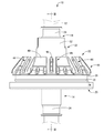
- FIG. 3 The perspective view which shows the state by which the grommet as one Embodiment of this invention was armored by the wire harness.
- the front view of FIG. FIG. 3 is a cross-sectional view taken along the line III-III in FIG. 2, showing a state of being fixed to a fixing member.
- FIGS. 1 to 3 show a state in which a grommet 10 as an embodiment of the present invention is sheathed on a wire harness 12.
- the grommet 10 has a substantially cylindrical shape and a small-diameter cylindrical portion 14 that extends in the axial direction (vertical direction in FIG. 3), and a vehicle body panel 16 that is a fixed member located on one side in the axial direction (lower side in FIG. 3).
- a thick large-diameter cylindrical portion 20 fitted into the formed through-hole 18 and a small diameter by extending from the other axial side (upper side in FIG. 3) toward the large-diameter cylindrical portion 20.
- a dome-shaped enlarged diameter cylindrical portion 22 that connects between the cylindrical portion 14 and the large diameter cylindrical portion 20, and includes EPDM (ethylene propylene rubber), CR (chloroprene rubber), SI (silicone rubber), and the like.
- EPDM ethylene propylene rubber
- CR chloroprene rubber
- SI silicone rubber
- the rubber material is integrally formed.
- “upper” means the upper side in FIGS. 2 and 3
- “lower” means the lower side in FIGS.
- the wire harness 12 is shown in phantom lines in FIGS.
- the small-diameter cylindrical portion 14 is configured to extend over substantially the entire length of the grommet 10 in the axial direction (vertical direction in FIG. 3).
- a tape fixing portion 24 is formed.
- the tape fixing portion 24 has a shape in which a peripheral wall at a position facing the radial direction at the opening end portion is cut out in a substantially rectangular shape.
- the tape fixing part 24 can be elastically deformed inward in the radial direction, so that the tape fixing part 24 is reduced in diameter by winding a binding tape (not shown) around the outer periphery of the tape fixing part 24.
- the small diameter cylindrical portion 14 can be fixed to the outer peripheral surface of the wire harness 12.
- the large-diameter cylindrical portion 20 has an annular groove 26 that opens to the outer peripheral surface and extends in a substantially rectangular cross-sectional shape over the entire circumference in the circumferential direction of the outer peripheral surface. Is formed.
- the grommet 10 of this embodiment is fixed to the vehicle body panel 16 by the outer peripheral part of the annular through-hole 18 formed in the vehicle body panel 16 being externally fitted and fixed to the annular groove 26. It is like that.
- a seal rib 30 (see FIGS. 2 and 3) is provided on the bottom surface 28 of the annular groove 26 so as to project in an annular shape with a substantially semicircular cross-sectional shape over the entire circumference of the annular groove 26.
- the seal rib 30 is deformed to the inside of the annular groove 26 on the bottom surface 28 of the annular groove 26. It protrudes at a position outside the region 34.
- the deformation region 34 here refers to the inside of the annular groove 26 because the small-diameter cylindrical portion side peripheral wall portion 32 of the annular groove 26 passes through the through hole 18 when the grommet 10 is attached to the vehicle body panel 16.
- trajectory 38 and the bottom face 28 which the top part 36 of the small diameter cylinder part side peripheral wall part 32 passes when falling down is said.
- the vehicle body panel 16 is described by virtual lines, and in the enlarged view, the vehicle body panel 16 is not described and the locus 38 is described by virtual lines.
- the enlarged diameter cylindrical portion 22 includes a small diameter cylindrical portion side end 40 that is spaced apart from the outer peripheral side of the small diameter cylindrical portion 14, and an inner circumference of the enlarged diameter cylindrical portion 22.
- a flexible connecting portion 42 having a substantially V-shaped cross section in a front view connecting the surface to the small diameter cylindrical portion 14 is provided.
- a plurality of contact ribs 44 (eight in the present embodiment) having a substantially rectangular shape in front view extending toward the front are projected. In the central portion of the contact rib 44 in the width direction, a substantially rectangular hollow hole 46 is formed on the outer peripheral surface when viewed from the front.
- the connecting position on the inner peripheral surface of the enlarged diameter cylindrical portion 22 is shifted to the large diameter cylindrical portion 20 side from the small diameter cylindrical portion side end portion 40. Configured in position.
- the intermediate region 48 that extends between the enlarged-diameter cylindrical portion-side coupling portion 42a and the small-diameter cylindrical portion-side coupling portion 42b constituting the flexible coupling portion 42 is bent in a convex shape toward the large-diameter cylindrical portion 20 side. Is formed.
- the diameter-expanded tube portion side connecting portion 42a of the flexible connecting portion 42 extends substantially parallel to the small diameter tube portion-side connecting portion 42b of the flexible connecting portion 42, and the other side in the axial direction (FIG. 3).
- An intermediate cylinder portion 50 is formed in a substantially cylindrical shape that is concentric and large in diameter toward the middle (upper side) and extends to a position that does not reach the tape fixing portion 24 of the small diameter cylinder portion 14.
- a tape fixing part 52 is formed at the extended end of the intermediate cylinder part 50. As shown in FIG. 1, the tape fixing portion 52 has a shape in which a peripheral wall at a position facing the radial direction at the opening end portion is cut out into a substantially rectangular shape.
- the tape fixing part 52 can be elastically deformed inward in the radial direction, so that the tape fixing part 52 is reduced in diameter by winding a binding tape (not shown) around the outer periphery of the tape fixing part 52.
- the intermediate cylinder part 50 can be fixed to the outer peripheral surface of the small diameter cylinder part 14. As a result, a sound insulation sealed space 54 surrounded by the intermediate cylinder part 50, the small diameter cylinder part 14, and the flexible connecting part 42 is formed.
- the seal rib 30 projecting from the bottom surface 28 of the annular groove 26 is formed inward of the annular groove 26 on the small-diameter cylindrical portion side peripheral wall portion 32 of the annular groove 26. It protrudes at a position outside the deformation region 34.
- the grommet 10 when the grommet 10 is attached to the vehicle body panel 16, the deformation of the small-diameter cylindrical portion side peripheral wall portion 32 is allowed smoothly, and the insertion force of the grommet 10 can be reduced.
- the seal rib 30 protrudes from the bottom surface 28 of the annular groove 26 at a position outside the deformation region 34 inward of the annular groove 26 inside the small-diameter cylindrical portion side peripheral wall portion 32, the seal rib 30 is provided on the vehicle body. The panel 16 is reliably brought into contact with the peripheral edge portion of the through hole 18 to ensure the waterproofness of the grommet 10 by the seal rib 30.
- the sub seal rib 60 may be further protrudingly provided by the large diameter cylinder side peripheral wall part 58 of the annular groove 26.
- FIG. As a result, the deformation of the large-diameter cylindrical portion side peripheral wall portion 58 is advantageously limited, so that the seal rib 30 is provided in a portion relatively close to the large-diameter cylindrical portion-side peripheral wall portion 58, thereby When the bottom surface 28 of 26 is pressed against the peripheral portion of the through hole 18, the possibility of deformation so as to obliquely intersect the peripheral portion of the through hole 18 is reduced.
- the grommet 56 can be more stably attached to the through hole 18 of the vehicle body panel 16.
- the sub seal rib 60 is newly provided, the waterproofness of the grommet 56 is further ensured together with the seal rib 30.
- the seal rib 30 protrudes at the same position as in the above embodiment. Therefore, when the grommet 56 is attached to the vehicle body panel 16 as in the above embodiment, the small diameter cylindrical portion side peripheral wall portion is provided. The deformation of 32 is allowed smoothly, and the insertion force of the grommet 56 can be reduced.
Abstract
グロメットの防水性を確保しつつ、貫通孔への挿入力の低減を図ることができる、新規な構造のグロメットを提供すること。 ワイヤハーネス12の外周面に固定される小径筒部14と、固定部材16の貫通孔18に固定される大径筒部20と、小径筒部14と大径筒部20の間を連結する拡径筒部22とを備え、大径筒部20の外周面に開口して貫通孔18の周縁部が外嵌固定される環状凹溝26の底面28に、シールリブ30が突設されてなるグロメット10において、シールリブ30が、環状凹溝26の底面28において、環状凹溝26の小径筒部側周壁部32の環状凹溝26内方への変形領域34を外れた位置に突設されているようにした。
Description
本発明は、ワイヤハーネスに外装された状態で、車体パネル等の固定部材に形成された貫通孔に装着されるグロメットに関するものである。
従来から、自動車に配索されるワイヤハーネスが、エンジンルームなどの車室外と車室内を仕切る車体パネル等の固定部材を跨いで配索される場合には、グロメットが、ワイヤハーネスに外装された状態で、車体パネルに形成された貫通孔に装着されている。このグロメットは、ワイヤハーネスの外周面に密接して固定される小径筒部と、車体パネルの貫通孔に密嵌固定される環状凹溝が設けられた大径筒部と、それらの間を連結する拡径筒部が一体的に設けられた構造とされており、貫通孔を通じた車室外から車室内への水の浸入などが防止されるようになっている。
ところで、かかるグロメットを車体パネルの貫通孔に高い防水性を持って密嵌固定するために、実開平1-68625号公報(特許文献1)等に記載されているように、大径筒部の環状凹溝の底面に、貫通孔の周縁部に当接して押しつぶされるシールリブを突設して設けた構造が広く採用されている。
ところが、このようなシールリブが大径筒部の環状凹溝の底面に突設されていると、グロメットの貫通孔への挿入作業に必要な挿入力が大きくなる傾向にあった。すなわち、グロメットを小径筒部側から車体パネルの貫通孔に挿通して、拡径筒部や大径筒部を圧縮変形させつつ貫通孔を通過させて、大径筒部の環状凹溝に貫通孔の周縁部を嵌め入れる際に、環状凹溝を画成する小径筒部側周壁部が環状凹溝の内部に倒れ込むように変形する。その際、小径筒部側周壁部が環状凹溝の底面に設けられたシールリブに当接することで、小径筒部側周壁部の変形が制限されて、大径筒部の小径筒部側周壁部が貫通孔を乗り越える際の挿入力が高くなることが避けられなかったのである。
本発明は、上述の事情を背景に為されたものであって、その解決課題は、グロメットの防水性を確保しつつ、貫通孔への挿入力の低減を図ることができる、新規な構造のグロメットを提供することにある。
本発明の第一の態様は、ワイヤハーネスの外周面に固定される小径筒部と、固定部材の貫通孔に固定される大径筒部と、前記小径筒部と前記大径筒部の間を連結する拡径筒部とを備え、前記大径筒部の外周面に開口して前記貫通孔の周縁部が外嵌固定される環状凹溝の底面に、シールリブが突設されてなるグロメットにおいて、前記シールリブが、前記環状凹溝の前記底面において、前記環状凹溝の小径筒部側周壁部の前記環状凹溝内方への変形領域を外れた位置に突設されていることを特徴とする。
本態様によれば、環状凹溝の底面に突設されたシールリブが、環状凹溝の小径筒部側周壁部の環状凹溝内方への変形領域を外れた位置に突設されていることから、大径筒部における小径筒部側周壁部が貫通孔を通過するために環状凹溝の内方に倒れ変形する際に、シールリブに当接して小径筒部側周壁部の変形が制限乃至は阻止されることが未然に防止されている。それゆえ、貫通孔を通過する際に小径筒部側周壁部の変形がスムーズに許容されて、挿入力の低減が図られる。
しかも、シールリブが、小径筒部側周壁部の環状凹溝内方への変形領域を外れた位置において、環状凹溝の底面に突設されていることから、シールリブによるグロメットの防水性の確保は担保されている。
なお、小径筒部側周壁部の環状凹溝内方への変形領域とは、小径筒部側周壁部が底面へ向かって倒れ変形した場合に、小径筒部側周壁部の頂部がとおる軌跡と底面によって囲われた領域を言う。
本発明の第二の態様は、前記第一の態様に記載のものにおいて、前記環状凹溝の大径筒部側周壁部にサブシールリブが突設されているものである。
本態様によれば、大径筒部側周壁部にサブシールリブが突設されていることから、環状凹溝の底面に突設されたシールリブが小径筒部側周壁部の変形領域を外れた位置、すなわち、大径筒部側周壁部に比較的近寄った部位に設けられていることにより、環状凹溝の底面が貫通孔の周縁部に対して斜交するおそれが低減されており、グロメットを一層安定して貫通孔に装着することができる。
本発明によれば、環状凹溝の底面に突設されたシールリブが、環状凹溝の小径筒部側周壁部の環状凹溝内方への変形領域を外れた位置に突設されていることから、大径筒部における小径筒部側周壁部が貫通孔を通過するために環状凹溝の内方に倒れ変形する際に、シールリブに当接して小径筒部側周壁部の変形が制限乃至は阻止されることが未然に防止されている。それゆえ、貫通孔を通過する際に小径筒部側周壁部の変形がスムーズに許容されて、挿入力の低減が図られる。しかも、シールリブが、小径筒部側周壁部の環状凹溝内方への変形領域を外れた位置にあることから、グロメットの防水性も担保されている。
以下、本発明の実施形態について、図面を参照しつつ説明する。
図1~3には、本発明の一実施形態としてのグロメット10がワイヤハーネス12に外装された状態が示されている。グロメット10は、略円筒形状で軸方向(図3中、上下方向)に延びる小径筒部14と、軸方向一方の側(図3中、下側)に位置して固定部材たる車体パネル16に形成された貫通孔18に嵌合される厚肉の大径筒部20と、軸方向他方の側(図3中、上側)から大径筒部20に向かって拡径して延出して小径筒部14と大径筒部20の間を連結するドーム状の拡径筒部22とを備えて構成されており、EPDM(エチレンプロピレンゴム)、CR(クロロプレンゴム)、SI(シリコーンゴム)等のゴム材料によって一体的に形成されている。なお、以下の説明において、上方とは、図2,3中の上方、下方とは、図2,3中の下方を言うものとする。また、理解を容易とするため、図1~3では、ワイヤハーネス12を仮想線で記載している。
図3に示されているように、小径筒部14は、グロメット10の軸方向(図3中、上下方向)の略全長に亘って延出して構成されており、軸方向の両端部にはテープ固定部24が形成されている。かかるテープ固定部24は、図1に示されているように、その開口端部において径方向に対向する位置の周壁が略矩形状に切り欠かれた形状とされている。これにより、テープ固定部24は径方向内方に向かって弾性変形可能とされていることから、テープ固定部24の外周に図示しない結束テープを巻き付けることにより、テープ固定部24を縮径して小径筒部14をワイヤハーネス12の外周面に固定できるようになっている。
一方、大径筒部20には、図1~3に示されているように、外周面に開口しかつ外周面の周方向の全周に亘って略矩形断面形状で延びる環状凹溝26が形成されている。そして、かかる環状凹溝26に対して、車体パネル16に形成された円環状の貫通孔18の周縁部が外嵌固定されることにより、本実施形態のグロメット10が車体パネル16に固定されるようになっている。また、環状凹溝26の底面28には、環状凹溝26の全周に亘って略半円断面形状で環状に突出するシールリブ30(図2,図3参照)が設けられている。かかるシールリブ30は、図3中の拡大図に示されているように、環状凹溝26の底面28において、環状凹溝26の小径筒部側周壁部32の環状凹溝26内方への変形領域34を外れた位置に突設されている。ここでいう変形領域34とは、グロメット10を車体パネル16に装着する際に、環状凹溝26の小径筒部側周壁部32が貫通孔18を通過するために環状凹溝26の内方に倒れ変形した場合に、小径筒部側周壁部32の頂部36がとおる軌跡38と底面28によって囲われた領域を言う。なお、理解を容易とするため、図3では、車体パネル16を仮想線で記載すると共に、拡大図では、車体パネル16を記載せずかつ軌跡38を仮想線で記載している。
拡径筒部22には、図3に示されているように、小径筒部14の外周側に離隔して配設された小径筒部側端部40と、拡径筒部22の内周面を小径筒部14に連結する正面視で略V字断面形状の可撓性連結部42を有して構成されている。また、図1~2に示されているように、拡径筒部22の外周面上には、周方向で相互に離隔して、大径筒部20側から小径筒部側端部40に向かって延出する正面視で略矩形状の複数(本実施形態では8個)の当接リブ44が突設されている。かかる当接リブ44の幅方向中央部分には、正面視で略矩形状の肉抜き孔46が外周面に開口するように形成されている。
可撓性連結部42は、図3に示されているように、拡径筒部22の内周面における連結位置が、小径筒部側端部40よりも大径筒部20側にシフトした位置に構成されている。また、可撓性連結部42を構成する拡径筒部側連結部42aと小径筒部側連結部42bの間に広がる中間領域48が、大径筒部20側に向かって凸状に屈曲して形成されている。さらに、可撓性連結部42の拡径筒部側連結部42aには、可撓性連結部42の小径筒部側連結部42bと略平行に延び出して、軸方向他方の側(図3中、上側)に向かって小径筒部14と同心かつ大径とされた略円筒形状で小径筒部14のテープ固定部24に至らない位置まで延びる中間筒部50が形成されている。中間筒部50の延出端部にはテープ固定部52が形成されている。かかるテープ固定部52は、図1に示されているように、その開口端部において径方向に対向する位置の周壁が略矩形状に切り欠かれた形状とされている。これにより、テープ固定部52は径方向内方に向かって弾性変形可能とされていることから、テープ固定部52の外周に図示しない結束テープを巻き付けることにより、テープ固定部52を縮径して中間筒部50を小径筒部14の外周面に固定できるようになっている。これにより、中間筒部50、小径筒部14、可撓性連結部42で囲まれた遮音用密閉空間54が形成されるようになっている。
このような構造とされたグロメット10によれば、環状凹溝26の底面28に突設されたシールリブ30が、環状凹溝26の小径筒部側周壁部32の環状凹溝26内方への変形領域34を外れた位置に突設されている。これにより、グロメット10を車体パネル16に装着する際に、環状凹溝26の小径筒部側周壁部32が貫通孔18を通過するために環状凹溝26の内方に倒れ変形した場合に、シールリブ30に当接して小径筒部側周壁部32の変形が制限乃至は阻止されることが未然に防止されるようになっている。それゆえ、グロメット10を車体パネル16に装着する際に小径筒部側周壁部32の変形がスムーズに許容されて、グロメット10の挿入力の低減が可能となっている。しかも、シールリブ30が、環状凹溝26の底面28において小径筒部側周壁部32の環状凹溝26内方への変形領域34を外れた位置に突設されていることから、シールリブ30が車体パネル16の貫通孔18の周縁部に対して確実に当接されて、シールリブ30によるグロメット10の防水性の確保が担保されている。
以上、本発明の実施形態について詳述したが、本発明はこれらの具体的な記載によって限定されない。例えば、図4に示されている別の態様のグロメット56のように、さらに環状凹溝26の大径筒部側周壁部58にサブシールリブ60が突設されていてもよい。これにより大径筒部側周壁部58が変形することが有利に制限されることから、シールリブ30が大径筒部側周壁部58に比較的近い部位に設けられていることによって、環状凹溝26の底面28が貫通孔18の周縁部に押圧された際に貫通孔18の周縁部に対して斜交するように変形するおそれが低減されている。それゆえ、グロメット56を一層安定して車体パネル16の貫通孔18に装着することができるようになっている。しかも、サブシールリブ60を新たに設けたことにより、シールリブ30と併せてグロメット56の防水性の一層の確保が担保されている。なお、本実施形態においても、シールリブ30は上記実施形態と同じ位置に突設されていることから、上記実施形態と同様に、グロメット56を車体パネル16に装着する際に小径筒部側周壁部32の変形がスムーズに許容されて、グロメット56の挿入力の低減が可能となっている。
10,56:グロメット、12:ワイヤハーネス、14:小径筒部、16:車体パネル(固定部材)、18:貫通孔、20:大径筒部、22:拡径筒部、26:環状凹溝、28:底面、30:シールリブ、32:小径筒部側周壁部、34:変形領域、58:大径筒部側周壁部、60:サブシールリブ
Claims (2)
- ワイヤハーネスの外周面に固定される小径筒部と、固定部材の貫通孔に固定される大径筒部と、前記小径筒部と前記大径筒部の間を連結する拡径筒部とを備え、
前記大径筒部の外周面に開口して前記貫通孔の周縁部が外嵌固定される環状凹溝の底面に、シールリブが突設されてなるグロメットにおいて、
前記シールリブが、前記環状凹溝の前記底面において、前記環状凹溝の小径筒部側周壁部の前記環状凹溝内方への変形領域を外れた位置に突設されている
ことを特徴とするグロメット。 - 前記環状凹溝の大径筒部側周壁部にサブシールリブが突設されている請求項1に記載のグロメット。
Applications Claiming Priority (2)
| Application Number | Priority Date | Filing Date | Title |
|---|---|---|---|
| JP2016-057811 | 2016-03-23 | ||
| JP2016057811A JP2017175742A (ja) | 2016-03-23 | 2016-03-23 | グロメット |
Publications (1)
| Publication Number | Publication Date |
|---|---|
| WO2017163801A1 true WO2017163801A1 (ja) | 2017-09-28 |
Family
ID=59899956
Family Applications (1)
| Application Number | Title | Priority Date | Filing Date |
|---|---|---|---|
| PCT/JP2017/008233 WO2017163801A1 (ja) | 2016-03-23 | 2017-03-02 | グロメット |
Country Status (2)
| Country | Link |
|---|---|
| JP (1) | JP2017175742A (ja) |
| WO (1) | WO2017163801A1 (ja) |
Cited By (1)
| Publication number | Priority date | Publication date | Assignee | Title |
|---|---|---|---|---|
| US11404185B2 (en) * | 2020-02-03 | 2022-08-02 | Yazaki Corporation | Water-stop grommet and wire harness |
Citations (4)
| Publication number | Priority date | Publication date | Assignee | Title |
|---|---|---|---|---|
| JPH0218217U (ja) * | 1988-07-22 | 1990-02-06 | ||
| JPH07296660A (ja) * | 1994-04-21 | 1995-11-10 | Inoac Corp | グロメット |
| JPH0950854A (ja) * | 1995-08-09 | 1997-02-18 | Yazaki Corp | コネクタ防水構造及びコネクタ組付方法 |
| JP2005228582A (ja) * | 2004-02-12 | 2005-08-25 | Yazaki Corp | グロメット |
-
2016
- 2016-03-23 JP JP2016057811A patent/JP2017175742A/ja active Pending
-
2017
- 2017-03-02 WO PCT/JP2017/008233 patent/WO2017163801A1/ja active Application Filing
Patent Citations (4)
| Publication number | Priority date | Publication date | Assignee | Title |
|---|---|---|---|---|
| JPH0218217U (ja) * | 1988-07-22 | 1990-02-06 | ||
| JPH07296660A (ja) * | 1994-04-21 | 1995-11-10 | Inoac Corp | グロメット |
| JPH0950854A (ja) * | 1995-08-09 | 1997-02-18 | Yazaki Corp | コネクタ防水構造及びコネクタ組付方法 |
| JP2005228582A (ja) * | 2004-02-12 | 2005-08-25 | Yazaki Corp | グロメット |
Cited By (1)
| Publication number | Priority date | Publication date | Assignee | Title |
|---|---|---|---|---|
| US11404185B2 (en) * | 2020-02-03 | 2022-08-02 | Yazaki Corporation | Water-stop grommet and wire harness |
Also Published As
| Publication number | Publication date |
|---|---|
| JP2017175742A (ja) | 2017-09-28 |
Similar Documents
| Publication | Publication Date | Title |
|---|---|---|
| WO2012124203A1 (ja) | グロメットのシール構造 | |
| US9096185B2 (en) | Grommet | |
| CN108713279B (zh) | 索环 | |
| JP2009296736A (ja) | グロメット | |
| US11404185B2 (en) | Water-stop grommet and wire harness | |
| JP2018046704A (ja) | グロメットの車体取付け構造 | |
| WO2017221675A1 (ja) | グロメット及びワイヤハーネス | |
| JP7104014B2 (ja) | グロメット | |
| CN112751296A (zh) | 护线套 | |
| US8895860B2 (en) | Grommet | |
| US10300868B2 (en) | Grommet and wire harness | |
| JP2009296741A (ja) | グロメット | |
| WO2017163801A1 (ja) | グロメット | |
| CN112744167A (zh) | 护线套 | |
| JP3431273B2 (ja) | グロメット | |
| CN112751295B (zh) | 护线套 | |
| WO2021166579A1 (ja) | グロメット | |
| JP2022038668A (ja) | グロメット | |
| WO2022181362A1 (ja) | グロメット | |
| JP7413923B2 (ja) | グロメット | |
| JP5724740B2 (ja) | グロメット | |
| WO2022186333A1 (ja) | グロメットユニット及びワイヤハーネス | |
| US20240136092A1 (en) | Grommet | |
| JP5533365B2 (ja) | グロメット装着部の遮音構造 | |
| JP2023084065A (ja) | グロメット及びワイヤーハーネス |
Legal Events
| Date | Code | Title | Description |
|---|---|---|---|
| NENP | Non-entry into the national phase |
Ref country code: DE |
|
| 121 | Ep: the epo has been informed by wipo that ep was designated in this application |
Ref document number: 17769846 Country of ref document: EP Kind code of ref document: A1 |
|
| 122 | Ep: pct application non-entry in european phase |
Ref document number: 17769846 Country of ref document: EP Kind code of ref document: A1 |