WO2017163801A1 - Passe-fil - Google Patents
Passe-fil Download PDFInfo
- Publication number
- WO2017163801A1 WO2017163801A1 PCT/JP2017/008233 JP2017008233W WO2017163801A1 WO 2017163801 A1 WO2017163801 A1 WO 2017163801A1 JP 2017008233 W JP2017008233 W JP 2017008233W WO 2017163801 A1 WO2017163801 A1 WO 2017163801A1
- Authority
- WO
- WIPO (PCT)
- Prior art keywords
- diameter cylindrical
- cylindrical portion
- grommet
- annular groove
- small
- Prior art date
Links
Images


Classifications
-
- B—PERFORMING OPERATIONS; TRANSPORTING
- B60—VEHICLES IN GENERAL
- B60R—VEHICLES, VEHICLE FITTINGS, OR VEHICLE PARTS, NOT OTHERWISE PROVIDED FOR
- B60R16/00—Electric or fluid circuits specially adapted for vehicles and not otherwise provided for; Arrangement of elements of electric or fluid circuits specially adapted for vehicles and not otherwise provided for
- B60R16/02—Electric or fluid circuits specially adapted for vehicles and not otherwise provided for; Arrangement of elements of electric or fluid circuits specially adapted for vehicles and not otherwise provided for electric constitutive elements
-
- H—ELECTRICITY
- H01—ELECTRIC ELEMENTS
- H01B—CABLES; CONDUCTORS; INSULATORS; SELECTION OF MATERIALS FOR THEIR CONDUCTIVE, INSULATING OR DIELECTRIC PROPERTIES
- H01B17/00—Insulators or insulating bodies characterised by their form
- H01B17/56—Insulating bodies
- H01B17/58—Tubes, sleeves, beads, or bobbins through which the conductor passes
-
- H—ELECTRICITY
- H02—GENERATION; CONVERSION OR DISTRIBUTION OF ELECTRIC POWER
- H02G—INSTALLATION OF ELECTRIC CABLES OR LINES, OR OF COMBINED OPTICAL AND ELECTRIC CABLES OR LINES
- H02G3/00—Installations of electric cables or lines or protective tubing therefor in or on buildings, equivalent structures or vehicles
- H02G3/22—Installations of cables or lines through walls, floors or ceilings, e.g. into buildings
Definitions
- the present invention relates to a grommet that is attached to a through-hole formed in a fixing member such as a vehicle body panel in a state of being sheathed on a wire harness.
- the grommet has been sheathed on the wire harness. In the state, it is mounted in a through hole formed in the vehicle body panel.
- This grommet connects between a small-diameter cylindrical portion that is closely fixed to the outer peripheral surface of the wire harness, a large-diameter cylindrical portion that is provided with an annular concave groove that is closely fitted and fixed to a through-hole of the vehicle body panel, and a gap between them.
- the diameter-expanding cylindrical portion is integrally provided so that water can be prevented from entering the vehicle compartment from the outside through the through hole.
- Patent Document 1 Japanese Utility Model Laid-Open No. 1-68625
- a structure is widely adopted in which a seal rib is provided on the bottom surface of the annular groove so as to protrude and abut against the peripheral edge of the through hole.
- the grommet is inserted into the through hole of the vehicle body panel from the small diameter cylindrical part side, and is passed through the through hole while compressing and deforming the enlarged diameter cylindrical part or the large diameter cylindrical part, and penetrates the annular concave groove of the large diameter cylindrical part.
- the small-diameter cylindrical portion side peripheral wall portion that defines the annular groove is deformed so as to fall into the annular groove.
- the deformation of the small-diameter cylindrical portion side peripheral wall portion is restricted by the small-diameter cylindrical portion-side peripheral wall portion coming into contact with the seal rib provided on the bottom surface of the annular groove, and the small-diameter cylindrical portion-side peripheral wall portion of the large-diameter cylindrical portion is limited. It was inevitable that the insertion force at the time of passing over the through-hole increased.
- the present invention has been made in the background of the above-mentioned circumstances, and the solution to the problem is a novel structure capable of reducing the insertion force into the through-hole while ensuring the waterproofness of the grommet. To provide grommets.
- the first aspect of the present invention includes a small-diameter cylindrical portion that is fixed to the outer peripheral surface of the wire harness, a large-diameter cylindrical portion that is fixed to a through-hole of the fixing member, and a space between the small-diameter cylindrical portion and the large-diameter cylindrical portion.
- a grommet having a sealing rib projecting from a bottom surface of an annular groove that opens to an outer peripheral surface of the large-diameter cylindrical portion and is fitted and fixed to a peripheral edge portion of the through-hole.
- the seal rib protrudes from the bottom surface of the annular groove at a position outside the deformation region inwardly of the annular groove on the side wall of the small diameter cylindrical portion of the annular groove.
- the seal rib projecting from the bottom surface of the annular groove is projected at a position outside the deformation region inward of the annular groove on the side wall of the small-diameter cylindrical portion of the annular groove.
- the seal rib protrudes from the bottom surface of the annular groove at a position outside the deformation region inward of the annular groove on the side wall of the small-diameter cylindrical portion, the waterproofness of the grommet by the seal rib is ensured. It is secured.
- the deformation region of the small-diameter cylindrical portion side peripheral wall portion toward the inside of the annular groove is a locus that the top of the small-diameter cylindrical portion-side peripheral wall portion passes when the small-diameter cylindrical portion-side peripheral wall portion is tilted toward the bottom surface.
- the area surrounded by the bottom is a locus that the top of the small-diameter cylindrical portion-side peripheral wall portion passes when the small-diameter cylindrical portion-side peripheral wall portion is tilted toward the bottom surface.
- a second aspect of the present invention is the one described in the first aspect, in which a sub seal rib is protruded from the peripheral wall portion on the large diameter cylindrical portion side of the annular groove.
- the sub seal rib protrudes from the large-diameter cylindrical portion side peripheral wall portion, the position where the seal rib protruded from the bottom surface of the annular concave groove deviates from the deformation region of the small-diameter cylindrical portion peripheral wall portion, That is, by being provided at a portion relatively close to the peripheral wall portion on the side of the large-diameter cylindrical portion, the possibility that the bottom surface of the annular groove is oblique to the peripheral portion of the through hole is reduced, and the grommet is further increased. It can be stably attached to the through hole.
- the seal rib protruding from the bottom surface of the annular groove is protruded at a position outside the deformation region inward of the annular groove on the side wall of the small-diameter cylindrical portion of the annular groove.
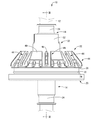
- FIG. 3 The perspective view which shows the state by which the grommet as one Embodiment of this invention was armored by the wire harness.
- the front view of FIG. FIG. 3 is a cross-sectional view taken along the line III-III in FIG. 2, showing a state of being fixed to a fixing member.
- FIGS. 1 to 3 show a state in which a grommet 10 as an embodiment of the present invention is sheathed on a wire harness 12.
- the grommet 10 has a substantially cylindrical shape and a small-diameter cylindrical portion 14 that extends in the axial direction (vertical direction in FIG. 3), and a vehicle body panel 16 that is a fixed member located on one side in the axial direction (lower side in FIG. 3).
- a thick large-diameter cylindrical portion 20 fitted into the formed through-hole 18 and a small diameter by extending from the other axial side (upper side in FIG. 3) toward the large-diameter cylindrical portion 20.
- a dome-shaped enlarged diameter cylindrical portion 22 that connects between the cylindrical portion 14 and the large diameter cylindrical portion 20, and includes EPDM (ethylene propylene rubber), CR (chloroprene rubber), SI (silicone rubber), and the like.
- EPDM ethylene propylene rubber
- CR chloroprene rubber
- SI silicone rubber
- the rubber material is integrally formed.
- “upper” means the upper side in FIGS. 2 and 3
- “lower” means the lower side in FIGS.
- the wire harness 12 is shown in phantom lines in FIGS.
- the small-diameter cylindrical portion 14 is configured to extend over substantially the entire length of the grommet 10 in the axial direction (vertical direction in FIG. 3).
- a tape fixing portion 24 is formed.
- the tape fixing portion 24 has a shape in which a peripheral wall at a position facing the radial direction at the opening end portion is cut out in a substantially rectangular shape.
- the tape fixing part 24 can be elastically deformed inward in the radial direction, so that the tape fixing part 24 is reduced in diameter by winding a binding tape (not shown) around the outer periphery of the tape fixing part 24.
- the small diameter cylindrical portion 14 can be fixed to the outer peripheral surface of the wire harness 12.
- the large-diameter cylindrical portion 20 has an annular groove 26 that opens to the outer peripheral surface and extends in a substantially rectangular cross-sectional shape over the entire circumference in the circumferential direction of the outer peripheral surface. Is formed.
- the grommet 10 of this embodiment is fixed to the vehicle body panel 16 by the outer peripheral part of the annular through-hole 18 formed in the vehicle body panel 16 being externally fitted and fixed to the annular groove 26. It is like that.
- a seal rib 30 (see FIGS. 2 and 3) is provided on the bottom surface 28 of the annular groove 26 so as to project in an annular shape with a substantially semicircular cross-sectional shape over the entire circumference of the annular groove 26.
- the seal rib 30 is deformed to the inside of the annular groove 26 on the bottom surface 28 of the annular groove 26. It protrudes at a position outside the region 34.
- the deformation region 34 here refers to the inside of the annular groove 26 because the small-diameter cylindrical portion side peripheral wall portion 32 of the annular groove 26 passes through the through hole 18 when the grommet 10 is attached to the vehicle body panel 16.
- trajectory 38 and the bottom face 28 which the top part 36 of the small diameter cylinder part side peripheral wall part 32 passes when falling down is said.
- the vehicle body panel 16 is described by virtual lines, and in the enlarged view, the vehicle body panel 16 is not described and the locus 38 is described by virtual lines.
- the enlarged diameter cylindrical portion 22 includes a small diameter cylindrical portion side end 40 that is spaced apart from the outer peripheral side of the small diameter cylindrical portion 14, and an inner circumference of the enlarged diameter cylindrical portion 22.
- a flexible connecting portion 42 having a substantially V-shaped cross section in a front view connecting the surface to the small diameter cylindrical portion 14 is provided.
- a plurality of contact ribs 44 (eight in the present embodiment) having a substantially rectangular shape in front view extending toward the front are projected. In the central portion of the contact rib 44 in the width direction, a substantially rectangular hollow hole 46 is formed on the outer peripheral surface when viewed from the front.
- the connecting position on the inner peripheral surface of the enlarged diameter cylindrical portion 22 is shifted to the large diameter cylindrical portion 20 side from the small diameter cylindrical portion side end portion 40. Configured in position.
- the intermediate region 48 that extends between the enlarged-diameter cylindrical portion-side coupling portion 42a and the small-diameter cylindrical portion-side coupling portion 42b constituting the flexible coupling portion 42 is bent in a convex shape toward the large-diameter cylindrical portion 20 side. Is formed.
- the diameter-expanded tube portion side connecting portion 42a of the flexible connecting portion 42 extends substantially parallel to the small diameter tube portion-side connecting portion 42b of the flexible connecting portion 42, and the other side in the axial direction (FIG. 3).
- An intermediate cylinder portion 50 is formed in a substantially cylindrical shape that is concentric and large in diameter toward the middle (upper side) and extends to a position that does not reach the tape fixing portion 24 of the small diameter cylinder portion 14.
- a tape fixing part 52 is formed at the extended end of the intermediate cylinder part 50. As shown in FIG. 1, the tape fixing portion 52 has a shape in which a peripheral wall at a position facing the radial direction at the opening end portion is cut out into a substantially rectangular shape.
- the tape fixing part 52 can be elastically deformed inward in the radial direction, so that the tape fixing part 52 is reduced in diameter by winding a binding tape (not shown) around the outer periphery of the tape fixing part 52.
- the intermediate cylinder part 50 can be fixed to the outer peripheral surface of the small diameter cylinder part 14. As a result, a sound insulation sealed space 54 surrounded by the intermediate cylinder part 50, the small diameter cylinder part 14, and the flexible connecting part 42 is formed.
- the seal rib 30 projecting from the bottom surface 28 of the annular groove 26 is formed inward of the annular groove 26 on the small-diameter cylindrical portion side peripheral wall portion 32 of the annular groove 26. It protrudes at a position outside the deformation region 34.
- the grommet 10 when the grommet 10 is attached to the vehicle body panel 16, the deformation of the small-diameter cylindrical portion side peripheral wall portion 32 is allowed smoothly, and the insertion force of the grommet 10 can be reduced.
- the seal rib 30 protrudes from the bottom surface 28 of the annular groove 26 at a position outside the deformation region 34 inward of the annular groove 26 inside the small-diameter cylindrical portion side peripheral wall portion 32, the seal rib 30 is provided on the vehicle body. The panel 16 is reliably brought into contact with the peripheral edge portion of the through hole 18 to ensure the waterproofness of the grommet 10 by the seal rib 30.
- the sub seal rib 60 may be further protrudingly provided by the large diameter cylinder side peripheral wall part 58 of the annular groove 26.
- FIG. As a result, the deformation of the large-diameter cylindrical portion side peripheral wall portion 58 is advantageously limited, so that the seal rib 30 is provided in a portion relatively close to the large-diameter cylindrical portion-side peripheral wall portion 58, thereby When the bottom surface 28 of 26 is pressed against the peripheral portion of the through hole 18, the possibility of deformation so as to obliquely intersect the peripheral portion of the through hole 18 is reduced.
- the grommet 56 can be more stably attached to the through hole 18 of the vehicle body panel 16.
- the sub seal rib 60 is newly provided, the waterproofness of the grommet 56 is further ensured together with the seal rib 30.
- the seal rib 30 protrudes at the same position as in the above embodiment. Therefore, when the grommet 56 is attached to the vehicle body panel 16 as in the above embodiment, the small diameter cylindrical portion side peripheral wall portion is provided. The deformation of 32 is allowed smoothly, and the insertion force of the grommet 56 can be reduced.
Landscapes
- Engineering & Computer Science (AREA)
- Architecture (AREA)
- Civil Engineering (AREA)
- Structural Engineering (AREA)
- Mechanical Engineering (AREA)
- Insulating Bodies (AREA)
- Installation Of Indoor Wiring (AREA)
Abstract
L'invention concerne un passe-fil ayant une nouvelle structure avec laquelle la force d'insertion dans un trou traversant peut être réduite tout en assurant la propriété d'étanchéité du passe-fil. Ce passe-fil 10 comporte : une partie de tube de petit diamètre 14 fixée à la surface circonférentielle extérieure d'un faisceau électrique 12 ; une partie de tube de grand diamètre 20 fixée à un trou traversant 18 d'un élément de fixation 16 ; et une partie de tube de diamètre d'expansion 22 qui couple la partie de tube de petit diamètre 14 et la partie de tube de grand diamètre 20, une nervure d'étanchéité 30 étant formée en faisant saillie à partir d'une surface inférieure 28 d'une rainure annulaire évidée 26 qui est ouverte sur la surface circonférentielle extérieure de la partie de tube de grand diamètre 20 et dans laquelle une section de bord périphérique du trou traversant 18 est ajustée et fixée vers l'extérieur. La nervure d'étanchéité 30 est disposée de façon à faire saillie à partir de la surface inférieure 28 de la rainure annulaire évidée 26 au niveau d'une position à l'extérieur d'une région de déformation 34 dans laquelle une partie de paroi périphérique 32 du côté partie de tube de petit diamètre de la rainure annulaire évidée 26 est déformée vers l'intérieur de la rainure annulaire évidée 26.
Applications Claiming Priority (2)
| Application Number | Priority Date | Filing Date | Title |
|---|---|---|---|
| JP2016057811A JP2017175742A (ja) | 2016-03-23 | 2016-03-23 | グロメット |
| JP2016-057811 | 2016-03-23 |
Publications (1)
| Publication Number | Publication Date |
|---|---|
| WO2017163801A1 true WO2017163801A1 (fr) | 2017-09-28 |
Family
ID=59899956
Family Applications (1)
| Application Number | Title | Priority Date | Filing Date |
|---|---|---|---|
| PCT/JP2017/008233 WO2017163801A1 (fr) | 2016-03-23 | 2017-03-02 | Passe-fil |
Country Status (2)
| Country | Link |
|---|---|
| JP (1) | JP2017175742A (fr) |
| WO (1) | WO2017163801A1 (fr) |
Cited By (1)
| Publication number | Priority date | Publication date | Assignee | Title |
|---|---|---|---|---|
| US11404185B2 (en) * | 2020-02-03 | 2022-08-02 | Yazaki Corporation | Water-stop grommet and wire harness |
Citations (4)
| Publication number | Priority date | Publication date | Assignee | Title |
|---|---|---|---|---|
| JPH0218217U (fr) * | 1988-07-22 | 1990-02-06 | ||
| JPH07296660A (ja) * | 1994-04-21 | 1995-11-10 | Inoac Corp | グロメット |
| JPH0950854A (ja) * | 1995-08-09 | 1997-02-18 | Yazaki Corp | コネクタ防水構造及びコネクタ組付方法 |
| JP2005228582A (ja) * | 2004-02-12 | 2005-08-25 | Yazaki Corp | グロメット |
-
2016
- 2016-03-23 JP JP2016057811A patent/JP2017175742A/ja active Pending
-
2017
- 2017-03-02 WO PCT/JP2017/008233 patent/WO2017163801A1/fr active Application Filing
Patent Citations (4)
| Publication number | Priority date | Publication date | Assignee | Title |
|---|---|---|---|---|
| JPH0218217U (fr) * | 1988-07-22 | 1990-02-06 | ||
| JPH07296660A (ja) * | 1994-04-21 | 1995-11-10 | Inoac Corp | グロメット |
| JPH0950854A (ja) * | 1995-08-09 | 1997-02-18 | Yazaki Corp | コネクタ防水構造及びコネクタ組付方法 |
| JP2005228582A (ja) * | 2004-02-12 | 2005-08-25 | Yazaki Corp | グロメット |
Cited By (1)
| Publication number | Priority date | Publication date | Assignee | Title |
|---|---|---|---|---|
| US11404185B2 (en) * | 2020-02-03 | 2022-08-02 | Yazaki Corporation | Water-stop grommet and wire harness |
Also Published As
| Publication number | Publication date |
|---|---|
| JP2017175742A (ja) | 2017-09-28 |
Similar Documents
| Publication | Publication Date | Title |
|---|---|---|
| WO2012124203A1 (fr) | Structure de joint pour passe-câble | |
| US9096185B2 (en) | Grommet | |
| US11404185B2 (en) | Water-stop grommet and wire harness | |
| CN108713279B (zh) | 索环 | |
| JP2009296736A (ja) | グロメット | |
| JP2018046704A (ja) | グロメットの車体取付け構造 | |
| WO2017221675A1 (fr) | Passe-fil et faisceau de fils | |
| JP7104014B2 (ja) | グロメット | |
| CN112751296A (zh) | 护线套 | |
| US8895860B2 (en) | Grommet | |
| US10300868B2 (en) | Grommet and wire harness | |
| JP2009296741A (ja) | グロメット | |
| WO2017163801A1 (fr) | Passe-fil | |
| US11186240B2 (en) | Grommet | |
| JP3431273B2 (ja) | グロメット | |
| CN112751295B (zh) | 护线套 | |
| WO2021166579A1 (fr) | Passe-fil | |
| JP2022038668A (ja) | グロメット | |
| WO2022181362A1 (fr) | Œillet | |
| JP7413923B2 (ja) | グロメット | |
| JP5724740B2 (ja) | グロメット | |
| WO2022186333A1 (fr) | Unité passe-fils et faisceau de câbles | |
| JP5533365B2 (ja) | グロメット装着部の遮音構造 | |
| JP2023084065A (ja) | グロメット及びワイヤーハーネス | |
| JP2016213096A (ja) | グロメット |
Legal Events
| Date | Code | Title | Description |
|---|---|---|---|
| NENP | Non-entry into the national phase |
Ref country code: DE |
|
| 121 | Ep: the epo has been informed by wipo that ep was designated in this application |
Ref document number: 17769846 Country of ref document: EP Kind code of ref document: A1 |
|
| 122 | Ep: pct application non-entry in european phase |
Ref document number: 17769846 Country of ref document: EP Kind code of ref document: A1 |